Local heat transfer and recovery factor with...
14
Pergamon /,,I .I Ilror Ma.,.\ Transfer. Vol 40. No IX. pp. 4295~43OX. 1991 I, 1997 Ekevier Science Ltd All nghts mewed Prmed m Great Rrltain 0017 Y310’97 $17 00+0.00 PII : soo17-9310(97)00054-9 Local heat transfer and recovery factor with impinging free-surface circular jets of transformer oil C. F. MA and Q. ZHENG Department of Thermal Science and Engineering, Beijing Polytechnic University, Beijing 100022, China and S. Y. KO Institute of Engineering Thermophysics, Chinese Academy of Sciences, Beijing 100080, China (Received 13 March 1997) Abstract-Measurements were made to investigate the local behavior of the recovery factor and the heat transfer coefficient with free-surface circular jets. The experiments were performed with transformer oil jets impinging on a vertical constant-heat-flux surface from small pipe and orifice nozzles of 1 mm diameter in the ranges of Re = 183-2600 and Pr = 82-337. Large values of recovery factor over 20 were recorded with medium jet velocity about 20 m SF’. Radial distribution of the recovery factor was determined and expressed in empirical equations. The heat transfer coefficient at stagnation point was found to be nearly independent of nozzle-to-plate spacing, but proportional to the square root of the jet Reynolds number. Profiles of local heat transfer coefficients were obtained and correlated. Based on the local measurements, integral average heat transfer coefficients were obtained and correlated. $;>1997 Elsevier Science Ltd. 1. INTRODUCTION Convection with impinging fluid jets is usually associ- ated with very high heat/mass transfer rates, par- ticularly with liquid as the working medium. Over the past three decades numerous investigations have been published in open literature on impingement heat transfer with air jets [l-3]. More recently, increasing attention was paid to the study of impinging liquid jets [4-71. For liquid jets, two operation modes are possible : submerged jets and free-surface jets. In the former a jet is discharged into stagnant fluid of the same type. In the latter, a liquid jet is exposed to a gaseous environment. Both the submerged and the free-surface liquid jets have found application in tech- nical processes. Some typical examples include oil jets in internal combustion engines [8], water or fluoro- carbon liquid jets in microelectronic devices [9-l 11, and water jets in metal hot rolling process [12]. With air as the working fluid, very high jet velocity can be reached in the laboratory or in industry. In this case, it is the difference between the target surface temperature and its adiabatic wall temperature, rather than the difference between the surface temperature and the jet static temperature, that should be used in the definition of heat transfer coefficient : h=4 T, - T,, (1) where the adiabatic wall temperature can be obtained from the equation T,, = T,+r& P The above concept was first proposed by Gardon and Cobonpue [13] for impingement heat transfer with high velocity air jets, then used by many inves- tigators [14-191 working in this area. Local charac- teristics of recovery factor and heat transfer coefficient were systematically studied with single circular air jets by Goldstein et al. [16] in the range of Reynolds number between 61000 and 124000. Stream wise dis- tributions of the two local coefficients were obtained. It was found that the recovery factor was significantly affected by the nozzle-to-plate spacing, but very slightly influenced by Reynolds number. With liquid as the working fluid, it is difficult to realize high vel- ocity for impinging jets. However, the adiabatic wall temperature may be considerably higher than the jet static temperature even at relatively lower jet velocity for a liquid of large viscosity. This temperature differ- ence mainly results from the heating effect due to viscous dissipation. The average adiabatic wall tem- perature was measured by Metzger et al. [19] with free-surface circular impinging jets of lubricating oil. The local characteristics of the recovery factor and the heat transfer coefficient with submerged transfer
Transcript of Local heat transfer and recovery factor with...

Pergamon
/,,I .I Ilror Ma.,.\ Transfer. Vol 40. No IX. pp. 4295~43OX. 1991 I, 1997 Ekevier Science Ltd All nghts mewed
Prmed m Great Rrltain 0017 Y310’97 $17 00+0.00
PII : soo17-9310(97)00054-9
Local heat transfer and recovery factor with impinging free-surface circular jets of
transformer oil C. F. MA and Q. ZHENG
Department of Thermal Science and Engineering, Beijing Polytechnic University, Beijing 100022, China
and
S. Y. KO Institute of Engineering Thermophysics, Chinese Academy of Sciences, Beijing 100080, China
(Received 13 March 1997)
Abstract-Measurements were made to investigate the local behavior of the recovery factor and the heat transfer coefficient with free-surface circular jets. The experiments were performed with transformer oil jets impinging on a vertical constant-heat-flux surface from small pipe and orifice nozzles of 1 mm diameter in the ranges of Re = 183-2600 and Pr = 82-337. Large values of recovery factor over 20 were recorded with medium jet velocity about 20 m SF’. Radial distribution of the recovery factor was determined and expressed in empirical equations. The heat transfer coefficient at stagnation point was found to be nearly independent of nozzle-to-plate spacing, but proportional to the square root of the jet Reynolds number. Profiles of local heat transfer coefficients were obtained and correlated. Based on the local measurements, integral average
heat transfer coefficients were obtained and correlated. $;> 1997 Elsevier Science Ltd.
1. INTRODUCTION
Convection with impinging fluid jets is usually associ- ated with very high heat/mass transfer rates, par- ticularly with liquid as the working medium. Over the past three decades numerous investigations have been published in open literature on impingement heat transfer with air jets [l-3]. More recently, increasing attention was paid to the study of impinging liquid jets [4-71. For liquid jets, two operation modes are possible : submerged jets and free-surface jets. In the former a jet is discharged into stagnant fluid of the same type. In the latter, a liquid jet is exposed to a gaseous environment. Both the submerged and the free-surface liquid jets have found application in tech- nical processes. Some typical examples include oil jets in internal combustion engines [8], water or fluoro- carbon liquid jets in microelectronic devices [9-l 11, and water jets in metal hot rolling process [12].
With air as the working fluid, very high jet velocity can be reached in the laboratory or in industry. In this case, it is the difference between the target surface temperature and its adiabatic wall temperature, rather than the difference between the surface temperature and the jet static temperature, that should be used in the definition of heat transfer coefficient :
h=4 T, - T,, (1)
where the adiabatic wall temperature can be obtained from the equation
T,, = T,+r& P
The above concept was first proposed by Gardon and Cobonpue [13] for impingement heat transfer with high velocity air jets, then used by many inves- tigators [14-191 working in this area. Local charac- teristics of recovery factor and heat transfer coefficient were systematically studied with single circular air jets by Goldstein et al. [16] in the range of Reynolds number between 61000 and 124000. Stream wise dis- tributions of the two local coefficients were obtained. It was found that the recovery factor was significantly affected by the nozzle-to-plate spacing, but very slightly influenced by Reynolds number. With liquid as the working fluid, it is difficult to realize high vel- ocity for impinging jets. However, the adiabatic wall temperature may be considerably higher than the jet static temperature even at relatively lower jet velocity for a liquid of large viscosity. This temperature differ- ence mainly results from the heating effect due to viscous dissipation. The average adiabatic wall tem- perature was measured by Metzger et al. [19] with free-surface circular impinging jets of lubricating oil. The local characteristics of the recovery factor and the heat transfer coefficient with submerged transfer

4296 C. F. MA et al.
NOMENCLATURE
a, aI empirical constants TV radial location where viscous A area of heated surface boundary layer reaches free surface C empirical constant Re u * d/v, Reynolds number C, specific heat at constant pressure T,W adiabatic wall temperature d jet nozzle diameter r, jet static temperature at nozzle h local heat transfer coefficient, equation exit
(1) TW wall temperature h’ local heat transfer coefficient, equation u mean fluid velocity at nozzle
(9) exit Z, Z, empirical constants z nozzle-to-plate spacing. Z current intensity k thermal conductivity of fluid empirical Greek symbols
constant I* dynamic viscosity k, empirical constant V kinematic viscosity m empirical constant l integral variable. n empirical constant Nu h * d/k, local Nusselt number Superscript P, PI empirical constants _ average values. Pr C, * p/k, Prandtl number 4 heat flux Subscripts r recovery factor, radial coordinate max maximum value R electrical resistance 0 stagnation point.
oil jets were studied by the present authors both exper- imentally [20] and numerically [21]. To the best of the knowledge of the present authors, the local charac- teristics of recovery factor with impinging free-surface jets of large Prandtl number liquid have not been reported in open literature. The objective of this work is to conduct an experimental study to investigate the local characteristics of the recovery factor and the heat transfer coefficient with single circular free-surface jets of transformer oil. Local distribution of the recovery factor and Nusselt number were obtained. The effects ofjet velocity, nozzle-to-plate spacing and nozzle con- figuration were studied in detail. Empirical formulas were developed to correlate the experimental results. Based on the local heat transfer data, average heat transfer rates were determined and correlated. The results of this work should be useful in cooling system of internal combustion engines.
2. EXPERIMENTAL APPARATUS AND METHOD
The experimental apparatus in this study is the same as that described in ref. [21] ; only a brief’description of the apparatus and procedure are given here. The test liquid used in this work was transformer oil. The working fluid was circulated in a closed loop that had provision for filtering, metering, preheating, and
cooling. The test section assembly was vertically fixed on one side of the test chamber. The main part was a strip of 10 pm thick constantan foil with a heated section of 5 x 10 mm (nominal) exposed to the cool- ant. The active section of the constantan foil was used as an electrically heating element as well as a heat transfer surface. The temperature at the center of the inner surface of the heater was measured by a 40 gage iron-constantan thermocouple that was electrically insulated from the foil yet in close thermal contact.
The oil jets issued from both pipe or orifice type nozzles. The former is a horizontal circular tube of 0.987 mm inside diameter and 35 mm length. The large length-to-diameter ratio ensures a fully developed laminar pipe flow at nozzle exit. The latter is a round hole of 1.048 mm diameter made in a brass plate of 1 mm thickness. The jet nozzle assembly was fixed on a three-dimensional coordinate rack and could be adjusted with respect to the test section with placements accomplished within fO.O1 mm. By rec- ording the center temperature of the heater for various locations of the jet nozzle the horizontal temperature distributions could be obtained for given jet condition and heat flux. Heat flux was calculated from the elec- trical power supplied to the test section and the area of one side of the heated surface by the following formula :
q=$

Recovery factor with circular jets of transformer oil
5.0
._ 3.0 -
k 5 0
??&$eFs . .
F 0 .Q O .o
. 0 0
2.0 * 0 0 0 .Q
0 0 0
(3 0 0 “e 0
0 1.0 - O 0 0
Fig. 1, Radial variation of adiabatic wall temperature.
4291
The jet static temperature was also measured by a 40 gauge iron-constantan thermocouple. The exper- iments were composed of two parts. First, the tem- perature distribution on the heater was measured when the heat flux was zero to provide adiabatic wall temperature and recovery factor distributions. Then, the wall temperature distribution was measured when the difference between the wall and jet temperatures was sustained at around 10 K to obtain the local heat transfer coefficient. The film temperature, the average of the wall and the jet temperature, was used for evaluating the fluid properties. The experimental uncertainties are given in detail in ref. [20].
3. RESULTS AND DISCUSSION
3.1. Recovery factor Difference between the adiabatic wall temperature
and the jet static temperature was measured directly at various jet velocities, nozzle-to-plate spacings and Prandtl numbers with both pipe-type and orifice-type nozzles. Some typical results for the two nozzles are plotted in Fig. 1. As shown in the figure, two maximum temperature differences in excess of 3 K appear near the stagnation point in the two profiles with the orifice and pipe type nozzles at jet velocities of 27.1 and 23.2 m s-‘, respectively. Apparently, neg- ligence of the recovery effect will result in significant error in the case of the present work.
The measurement results of adiabatic wall tem- perature are expressed in terms of recovery factor calculated from equation (2). Radial profiles of the local recovery factor for various Reynolds are plotted in Fig. 2 at a constant spacing of z/d = 4. For the orifice-type nozzle, the effect of the Reynolds number on the recovery factor is insignificant. With the pipe-
type nozzle the influence is somewhat more significant. It seems difficult to determine a clear trend of the variation of the recovery factor with the Reynolds number. However, all the profile curves are of a simi- lar shape. A valley appears at the stagnation point. With increasing of the radial distance the recovery factor sharply increases and reaches maxima at about r/d = + 1.5, then decreases monotonously. As shown in the figures, good symmetry of the distribution curves is observed about the stagnation point.
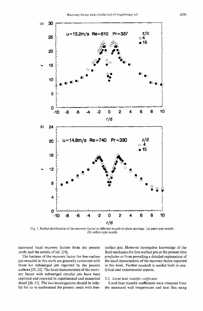
The effect of nozzle-to-plate spacing was examined experimentally. It is seen from Fig. 3 that the recovery factor is nearly independent of the spacing both for the two nozzles. The variations of maximum recovery factor and the recovery factor at the stagnation point with the nozzle-to-plate spacing at constant Reynolds number for the two type nozzles are presented in Fig. 4. As shown in the figure the recovery factors almost keep constant. The independence of the recovery factor on the spacing may be attributed to the weak mixing of the free-surface liquid jets with the sur- rounding air.
The effect of Prandtl number on the recovery factor was also studied experimentally. The measurement of the recovery factor was performed using the test sec- tion both with and without the constantan foil. The variation of the maximum recovery factor with the Prandtl number is presented in Fig. 5. The measured recovery factor using the test section without the con- stantan foil is slightly higher than that with the foil. Apparently, the difference was caused by the thermal conduction along the foil. However, the discrepancy is insignificant because of the extremely small thick- ness of the constantan foil (10 pm). The experimental data with or without the foil can be well correlated by the following empirical formulas, respectively.

C. F. MA et al.
(a) 30 1
z/d =4 25
Pr=3CtO u(m/s) Re 013.2 611 ??l7.1 669 o 23.2 1316
-10 -8 -6 -4 -2 0 2 4 6 a 10
(b) 30 L
r/d
z/d=4 Pr=244 u(m/s) Re ??16.1 1052 021.2 1394 ??25.0 1447
20 o 27.1 1913
8
8
??8 L 15
10 p
-10 -a -6 4 -2 0
r/d 2 4 6 a 10
Fig. 2. Radial distribution of the recovery factor for various Reynolds numbers : (a) pipe-type nozzle ; (b) orifice-type nozzle.
r max = 5.08Pr”.23 (4) r=fi (7)
rmaX = 5.53Pr”.24. (5) General agreement is seen between the present exper- imental data and the two correlations.
Also presented in the figure is the correlation from a numerical study for submerged circular jets [21] :
The experimental results of this work were also compared with the average recovery factors for cir-
rmar = 1.51Pr” 437 (6) cular free-surface jets of lubricating oil [19]. The local recovery factor distributions obtained in this study
Comparison is also made between the present data were numerically integrated r/d = 1.66 and r/d = 3.3 1 and the correlation developed for laminar flow along for comparison with ref. [19]. A general agreement is a flat plate [22] : seen from Fig. 6 between the averaged values of the
Recovery factor with circular jets of transformer oil 4299
(a) 30 1
z/d 04 015
%D QQ, I
-10 -8 4 4 8 10
09 24
20
16
L- 12
8
4
0
r/d
- u=14.8m/s Re=740 Pr=330 z/d 04 015
*h lh
$
00
od@ V Oo
Y.@@ a9 ?
% @O
0 08
4 -2 2 4
Fig. 3. Radial distribution of the recovery factor at different nozzle-to-plate spacings : (a) pipe-type nozzle: (b) orifice-type nozzle.
measured local recovery factors from the present study and the results of ref. [ 191.
The features of the recovery factor for free-surface jets revealed in this work are generally consistent with those for submerged jets reported by the present authors [20,21]. The local characteristics of the recov- ery factor with submerged circular jets have been explored and reported in experimental and numerical detail [20,21]. The two investigations should be help- ful for us to understand the present result with free-
surface jets. However incomplete knowledge of the fluid mechanics for free-surface jets at the present time precludes us from providing a detailed explanation of the local characteristic of the recovery factor reported in this work. Further research is needed both in ana- lytical and experimental aspects.
3.2. Local heat transfer coefficient Local heat transfer coefficients were obtained from
the measured wall temperature and heat flux using

4300 C. F. MA et al.
._ pipetype:
35 0;=13.2m/sRe=612Pr=337 .;=153m/sRe=887Pr=281
30 /_
orifloe type:
Km 0 stagnation point e 3tagnation point
0 2 4 6 8 lo 12 14 16 18 20
z/d Fig. 4. Variation of stagnation recovery factor and maximum recovery factor with the nozzle-to-plate
spacing at constant Reynolds number.
loo L ioe
u=25m/s Re=l!sm
r
-‘3” lrm-5mw
0 without foil o with foil
Id
IL
1 IO’ L 109 10'
v R/d=l.66 Metzgsr o R/d=3.31 Metqw . R/d=l.88 Present data . R/d-3.31 Present data
/ J
Id 108
R Pr
Fig. 5. Variation of maximum recovery factor with Prandtl Fig. 6. Variation of average recovery factor with Prandtl
number at constant Reynolds number. number.
equation (1) and (2). In order to estimate the effect of thermal dissipation, two heat transfer coefficients were calculated from the same experimental results with the recovery factors of measured value and zero, respec- tively. The ratio of the two coefficients can be expre- ssed by the following equation :
h' x=l-
e42/2c,) TW--T,
where h’ is defined as
(8)
,!,‘=L T,,,-7; (9)
Apparently, the error caused by neglecting the ther- mal dissipation effect increases with the increasing of the jet velocity and the temperature difference between the wall and the jet, as well as the recovery factor. Figure 7 displays a comparison between two radial profiles of considering the recovery effect and neg- lecting it. The maximum difference of up to 14% between the two curves occurs near the stagnation point as shown in Fig. 7 at the experimental conditions

Recovery factor with circular jets of transformer oil 4301
250 - ??-• 0 r=O ?? measured r
6.
200- ??o 0. Pr=181.7 . 0
Taw-Tj=8-lOS(*C) - 0 0.
z 150 -O. u=lQ.lm/s
r 0 I%=1629 .
-0
100 - 0
;
50- E, 6
e e CD
0 ~‘,,“,~l’~l,~‘,l~,‘l,‘,‘~,~~‘~,~,’L~l, -2 0 2 4 6 8 10 12 14
r/d Fig. 7. Local heat transfer distribution with and without considering recovery effect.
indicated in the figure. However, the difference decreases monotonically along the radial distance.
3.2.1. Heat transfer at stagnation point. Measure- ments were made of the local heat transfer at the stagnation point to determine the effects of jet Rey- nolds number and nozzle-to-plate spacing. Figure 8 illustrates the experimental result of the variation of NuO with spacing at three constant Reynolds numbers both for the pipe and orifice nozzles. It is observed from Fig. 8 that the stagnation point Nusselt number is not affected by the change of the nozzle-to-plate spacing within a critical value of the spacing. The critical nondimensional spacing z/d was determined experimentally to be about 4 and 8 for lower and higher Reynolds numbers, respectively. Beyond z/d = 4 or 8, a slight decline in Nusselt number was recorded with increasing of the spacing. However, in general, the stagnation point Nusselt number data exhibit somewhat insensitivity to nozzle-to-plate spac- ing for circular free-surface jets both with the two nozzles.
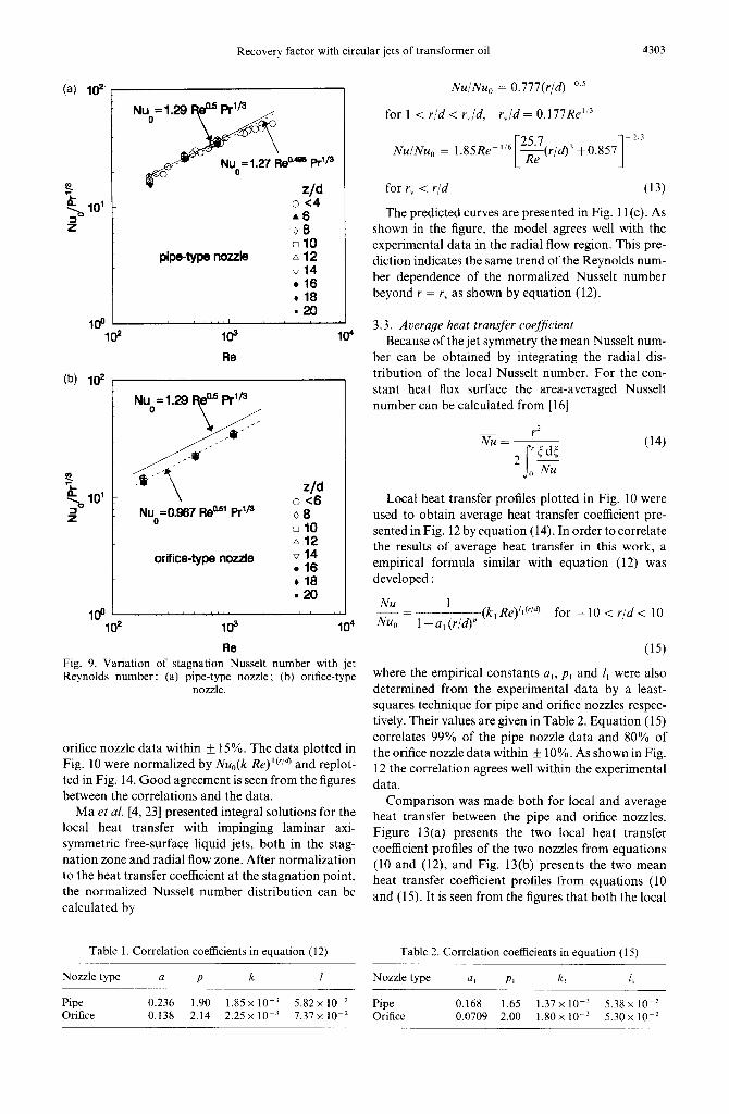
The variation of the stagnation point Nusselt num- ber with Reynolds number within z/d = 20 was shown in Fig. 9 for pipe and orifice nozzles. The data of the two nozzles indicate the same Reynolds number dependence which can be expressed by the correlation
Nu,, = CRe” Prli3 (10)
where the standard Prandtl number exponent of l/3 was adopted from the recommendation of refs. [15, 19, 23, 241, and the coefficients C and m were deter- mined from experimental data : C = 1.27, m = 0.495 for pipe nozzle, and C = 0.967, m = 0.510 for orifice
nozzle. The Reynolds number dependence of Nu,, by equation (10) indicates the laminar characteristics of the heat transfer at stagnation point. Equation (10) presents 76.4 and 100% of all the experimental data in the range 2 < z/d < 20 within + 10% for the pipe and orifice nozzles, respectively. Presented in Fig. 9 is also a correlation from ref. [15] for submerged and free-surface circular jets at the Reynolds and Prandtl number (z/d < 4), similar to those in the present work :
Nu, = 1.29 Re’.’ Pr’13. (11)
For the pipe-type nozzle, good agreement is seen between the experimental data and the correlation curves from equations (10) and (11). The good agree- ment can be explained by the fact that similar pipe- type nozzles were used in the experiments of the present work and refs. [lo, 151. However, there is 18% discrepancy between equation (10) and equation (11) for the orifice-type nozzle. So, the stagnation Nusselt number of the orifice-type nozzle is about 18% lower than the pipe-type nozzle. This fact may be explained by the enhancement of heat transfer resulting from the higher turbulence intensity at the pipe nozzle exit.
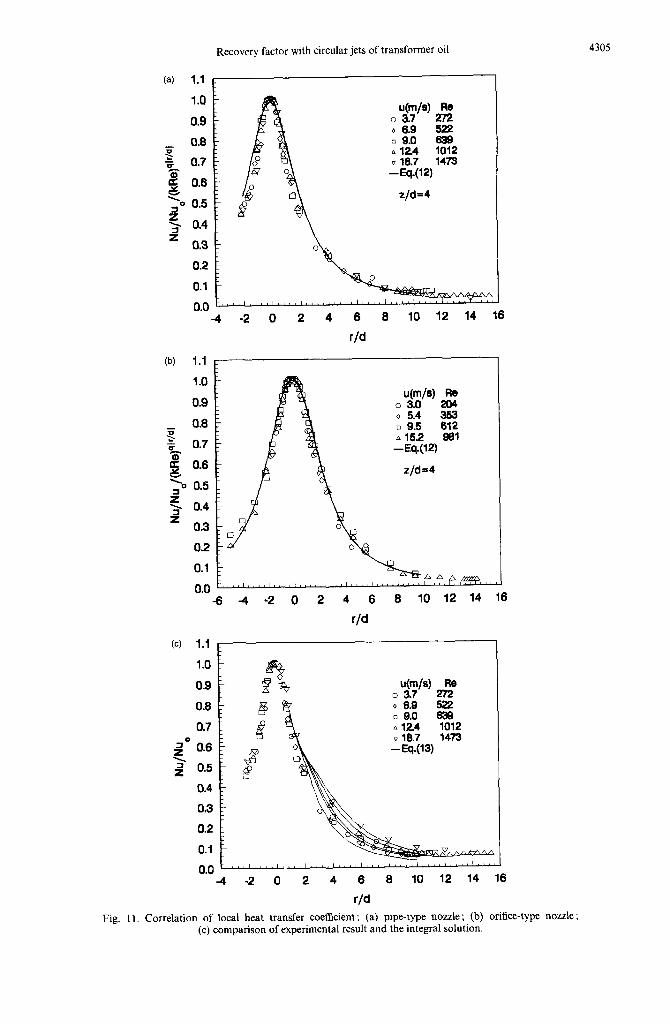
3.2.2. Radial profiles of local Nusselt number. Experimental result of radial distribution of local Nusselt number at z/d = 4 is given in Fig. 10. Five and four profiles were presented in Fig. 10 for the pipe and orifice nozzles, respectively. For all the profiles, the maximum heat transfer coefficient occurs at the stagnation point and declines with radial distance. It is observed from the figures that normalization to stagnation point Nusselt number is successful in col-

4302 C. F. MA et al.
(4
0 z
250
150
100
50
0
u(m/s) Re 0 3.5 211 v 6.4 420 0 11.7 813
I 000000000 *vvooovvvv
0 2 4 6 8 lo 12 14 16 18 20
z/d
(b) 800 u(m/s) Re
o 2.9 184 250 - 0 7.5 517
015.5 1099
-~~~~~~~~ooonoooo~oncl
Z’O 150 - -ooovvv~voovooooovooo
loo - -ooo"oooooooooooooooo
50 -
0 ~,,,',~~~'~~~~'~,~,"1'1'11"'1'11'1'1""1""' o 2 4 6 8 IO 12 14 16 18 20
z/d Fig. 8. Variation of stagnation Nusselt number with the nozzle-to-plate spacing at constant Reynolds
number : (a) pipe-type nozzle ; (b) orifice-type nozzle.
lapsing the data of the two nozzles. Independence of Nu 1 Nusselt number on Reynolds number is seen in the
_= NM, 1 + a(r/dy
(kRe)‘(“‘4 for - 10 < r/d < 10
stagnation zone (r/d < 2). In the wall jet zone (r/d > 2), the experimental profiles demonstrate a (12)
more gentle decay in Nusselt number along the radial where the empirical constants a, p, k and I were deter- direction when Reynolds number decreases. Taking mined from the experimental data by a least-squares into account the weak Reynolds number dependence technique for pipe and orifice nozzles, respectively. of the Nusselt number a correlation was developed to Their values are given in Table 1. Equation (12) cor-
predict the profiles relates 84% of the pipe nozzle data and 89% of the
Recovery factor with circular jets of transformer oil 4303
loo L ld
Nu =1.27 Re- Prlp
z/d 0 <4 A6 08 010
pipe-type nozzle a 12 014 ??16 + 18 120
104
Nu =129 ea5 PrlB 0. s /
z/d Nue=0.967 Rea5’ P@
0.~6 0 8 010 a12
orifice-type nozzle v 14 .16 b 18 -20
Fig. 9. Variation of stagnation Nusselt number with jet Reynolds number: (a) pipe-type nozzle; (b) orifice-type
nozzle.
orifice nozzle data within f 15%. The data plotted in Fig. 10 were normalized by Nu,(k &z)““~ and replot- ted in Fig. 14. Good agreement is seen from the figures between the correlations and the data.
Ma et al. [4, 231 presented integral solutions for the local heat transfer with impinging laminar axi- symmetric free-surface liquid jets, both in the stag- nation zone and radial flow zone. After normalization to the heat transfer coefficient at the stagnation point, the normalized Nusselt number distribution can be calculated by
Table 1. Correlation coefficients in equation (12) Table 2. Correlation coefficients in equation (15)
Nozzle type a P k I Nozzle type a, PI k, 1,
Nu!Nu, = 0.777(r/d)mo5
for 1 < r/d < r-,./d, r,/d = 0.177Relf3
Nu/Nuo = 1.85Re-
for r, -C r/d (13)
The predicted curves are presented in Fig. 11 (c). As shown in the figure, the model agrees well with the experimental data in the radial flow region. This pre- diction indicates the same trend of the Reynolds num- ber dependence of the normalized Nusselt number beyond r = r, as shown by equation (12).
3.3. Average heat transfer coef$cient Because of the jet symmetry the mean Nusselt num-
ber can be obtained by integrating the radial dis- tribution of the local Nusselt number. For the con- stant heat flux surface the area-averaged Nusselt number can be calculated from [ 161
r2 Nu = ~
2 ‘5d5
i- 0 Nu
(14)
Local heat transfer profiles plotted in Fig. 10 were used to obtain average heat transfer coefficient pre- sented in Fig. 12 by equation (14). In order to correlate the results of average heat transfer in this work, a empirical formula similar with equation (12) was developed :
NM 1 ---Z Nuo 1 +a, (r/W
(k, Re)‘l”‘” for - 10 < r/d < 10
(15)
where the empirical constants a,, p, and I, were also determined from the experimental data by a least- squares technique for pipe and orifice nozzles respec- tively. Their values are given in Table 2. Equation (15) correlates 99% of the pipe nozzle data and 80% of the orifice nozzle data within k 10%. As shown in Fig. 12 the correlation agrees well within the experimental data.
Comparison was made both for local and average heat transfer between the pipe and orifice nozzles. Figure 13(a) presents the two local heat transfer coefficient profiles of the two nozzles from equations (10 and (12), and Fig. 13(b) presents the two mean heat transfer coefficient profiles from equations (10 and (15). It is seen from the figures that both the local
Pipe 0.236 1.90 1.85 x 10-j 5.82 x IO-’ Pipe 0.168 1.65 1.37 x 10m3 5.38 x 10-l Orifice 0.138 2.14 2.25 x 10-j 7.37 x IO-’ Orifice 0.0709 2.00 1.80 x 10-j 5.30 x 10m2

4304 C. F. MA et al.
(4 300 1
I
260 -
2 160-
100 -
50 - 0
0 0 0
u(m/s) Re 0 3.7 272 o ii.9 ??9.0 E A 12.4 1012 v 18.7 1473
z/d=4
V A
0 V
(W 250
I
6
r/d
6 10 12 14 16
uOWs> 0 3.0
i
- %A
A
yo ??A
00 0
0 Oo En 00 0 ~AAA
Re
z!i 812 831
6 4 -2 0 2 4 6 6 10 12 14 16
r/d Fig. 10. Radial distributions of local Nusselt number : (a) pipe-type nozzle ; (b) orifice-type nozzle
Recovery factor with circular jets of transformer oil
;;
0.8 g 0.7
i! Y
0.6
2 0.5
f 0.4
= 0.3 i
utm’sJ 2z 0 3.7 06.9 522 ?? 9.0 839 A 124 1012 V 15.7 1473 --EN21
z/d=4
(b) 1.1
1.0
0.9
-rr 08 $ 0.7
g 0.6
2 0.5
f 0.4
= 0.3
uW) 0 3.0 g
0 5.4 353 ?? 9.5 612 A 152 981 --Eq.(l2)
z/d =4
,~,‘,,~1/11’1’11111”11”“’ -8 4 -2 0 2 4 6 8 10 12 14 16
0.8
0.7
DO 0.6 P 1 0.5
0.4
0.3
0.2
0.1
0.0 4 -2 0 2 4 6 8 10 12 14 16
4305
Fig. Il. Correlation of local heat transfer coefficient: (a) pipe-type nozzle; (b) orifice-type nozzle ; (c) comparison of experimental result and the integral solution.

4306 C. F. MA et al.
(a) 1.1
1.0
0.9
p 0.8 Z E- 0.7
4 0.8
e. 0.5
8 0.4
I= = 0.3
0.2
0.1
0.0
0 6.9 522 ?? 9.0 639 A 12.4 1012 v 16.7 1473 -Eq.(15)
0 2 4 6 8 10
(b) 1.1
r/d
012 3 4 5 6 7 8 9 10
r/d Fig. 12. Correlation of average heat transfer coefficient : (a) pipe-type nozzle ; (b) orifice-type nozzle

Recovery factor with circular jets of transformer oil 4307
(4 300
250
100
50
0
- --orifice-type nozzle
, I, , , , 11,1,,,,,,,/,,1,,,/,/,, -10 -8 -6 4 -2 0
r/d 2 4 6 8 10
lb) 300
- --orifiie-type nozzle
0 L’,,‘i’,~‘l,“‘l”“i,,‘,r”“l,,“I”,,,,’,’,,,,. -10 -8 -6 4 -2 0 2 4 6 8 10
Fig. 13. Comparison of the radial distribution of local heat transfer distribution between the pipe-type and orifice-type nozzles : (a) local heat transfer coefficient : (b) average heat transfer coefficient.

4308 C. F. MA et al.
and average heat transfer profiles for the pipe-type heat surfaces with single circular liquid jets. ASME Jour-
nozzle are higher than the profiles with the orifice nal ofHeat Transfer, 1993, 115, 106-I 15.
nozzle in the stagnation zone. As mentioned before, 8. Kiryu, M., Development of oil-cooled 7.50 cc motorcycle
the stagnation point heat transfer of the pipe-type engine. Automobile Technology, 1986,40(9), 1154-l 158, in Japanese.
nozzle is about 18% higher than that of the orifice- 9. Bar-Cohen. A., Thermal management ofelectronic com-
type nozzle. Beyond r/d = 1.8, both the local and aver- ponents with dielectric liquids. JSMEZnternational Jour-
age Nusselt numbers of the orifice nozzle are slightly nal, Series B, 1993,36(l), l-23.
higher than those of the pipe-type nozzle. However, 10. Ma, C. F. and Bergles, A. E., Boiling jet impingement
cooling of simulated microelectronic chips. ASME the difference in thermal performance in radial flow HTD-tol. 28, 1983, pp. 5-12. zone between the two nozzles is quite insignificant in 11. Wadsworth. D. C. and Mudawar. I.. Cooling of mul- , the range of the Reynolds number encountered in this work.
12
13
tichip electronic module by means of confined two- dimensional jets of dielectric liquid. ASME Journal of Heat Transfer, 1990, 112, 891-898.
4. CONCLUSIONS
An experimental study was conducted to charac- terize the local recovery factor and heat transfer coefficient with impinging circular free-surface jets of large Prandtl number liquid at low Reynolds number using both pipe and nozzle type nozzles. Large values over 20 were recorded for the recovery factor with the jet velocity about 20 m SC’. The recovery factor was determined to be nearly independent of both the Rey- nolds number and the nozzle-to-plate spacing. The dependence of the recovery factor on the Prandtl num- ber was examined and expressed with empirical for- mulas. Stagnation point Nusselt number data were collected and correlated. Radial profiles of both local and average heat transfer coefficient were also obtained and correlated. The pipe-type nozzle showed better heat transfer performance than the orifice-type nozzle in the stagnation zone.
Acknowledgements-This study was supported by the National Natural Science Foundation of China. The authors also appreciate Mr D. H. Lei and Profs Y. Q. Tian and Y. P. Can for their help in this work.
14
15
16
1.
2.
3.
4.
5.
6.
7.
REFERENCES
Martin, H., Heat and mass transfer between impinging 20. gas jets and solid surfaces. Advances in Heat Transfer, 1987, 13, l-60. Downs, H. T. and James, E. H., Jet impingement heat transfer-a literature survey. ASME Paper, 87-HT-35, 1987. 21 Hrycak, P., Heat transfer from impinging jets-a litera- ture review. Technical Report AFWAL-TR-81-3504, Flight Dynamics Laboratory, Wringht Patterson AFB, Ohio, 1981. Webb, B. W. and Ma, C.-F., Single phase liquid jet 22 impingement heat transfer. Advances in Heat Transfer, 1995,26, 105-217. Faggiani, S. and Grassi, W., Impingement liquid jets on 23 heated surface. In Proceedings of the Ninth International Heat Transfer Conference, Vol. 1, 1990, pp. 275-285. Ma, C. F., Liquid jet impingement heat transfer with or without boiling. In Proceedings of the 10th National Heat Transfer Congress, Genova, Italy, 1992, pp. 35-60. Also 24 in Journal of Thermal Science, 1993, 2(l), 3249. Womac, D. J., Ramadhyani, S. and Incropera, F. P., Correlating equations for impingement cooling of small
Kohing, F. C., Waterwall : water cooling systems. Iron- Steel Engineer, 1985, 62, 30-36. Gardon, R. and Cobonpue, J., Heat transfer between a flat plate and jets of air impinging on it. International Developments in Heat Transfer, International Heat Transfer Conference, University of Colorado, Co, U.S.A., 1962, pp. 454460. Jambunathan, K., Lai, E., Moss, M. A. and Button, B. L., A review of heat transfer data for single circular jet impingement. International Journal of Heat and Fluid Flow, 1992, 13(2), 106-l 15. Ma, C. F., Sun, H., Auracher, H. and Gomi, T., Local convective heat transfer from vertical heated surfaces to impinging circular jets of large Prandtl number liquid. Proceedings of the Ninth International Heat Transfer Conference. Hemisphere, New York, Vol. 2, 1990, pp. 441446. Goldstein, R. J., Behbahani, A. I. and Heppelman, K. K., Streamwise distribution of the recovery factor and the local heat transfer coefficient to an impinging circular air jet. International Journal of Heat and Mass Transfer. 1986,29(8), 1227-1235. Goldstein, R. J., Behbahani, A. I., Impingement of a circular jet with and without crossflow. International Journal of Heat and Mass Transfer, 1982,25,1377-l 382. Goldstein, R. J., Sobolik, K. A. and Seol, W. S., Effect of entrainment on the heat transfer to a heated circular air jet impinging on a flat surface. ASME Journal of Heat Transfer, 1990, 22,601-622. Metzger. D. E., Cummings, K. N. and Ruby, W. A., Effects of Prandtl number on heat transfer characteristics of impinging liquid jets. Proceedings of 5th International Heat Transjhr Conference, Hemisphere, New York, Vol. 2, 1974, pp. 20-24. Ma, C. F., Zheng, Q., Lee, X. C. and Gomi, T., Impinge- ment heat transfer and recovery effect with submerged jets of large Prandtl number liquid-I. Unconfined cir- cular jets. International Journal qf Heat and Mass Trans- f&-, 1997, 40(6), 1481-1490. Lee, X. C., Ma, C. F., Zheng, Q.. Zhang, Y. andTian, Y. Q., Numerical study of recovery effect and impingement heat transfer with submerged circular jets of large Prandtl number liquid. International Journal of Heat and Mass Transftir. 1997,40(11), 2647-2653. Eckert, E. ii. G. and Drake; R. M., Analysis of Heat and Mass Transfer. McGraw-Hill. New York. 1972, PU. 254 280 and ppy 417438.
. .
Ma, C. F., Zhao, H. Y., Masuoka, T. and Gomi, T., Analvtical study on impingement heat transfer with sin- gle-phase free-surface &c;lar liquid jets under arbitrary heat-flux condition. Journal of Thermal Science, 1996, S(4), 271-277. Sun, H., Ma, C. F. and Chen, Y. C., Prandtl number dependence of impingement heat transfer with circular free-srlrface liquid jets. International Journal of Heat and Mass Tramfer (in press).