
LOCAL AUTHORITY SPECIFIC REQUIREMENTS DEVELOPMENT MANUAL LOCAL AUTHORITY SPECIFIC REQUIREMENTS ......
20
CAIRNS REGIONAL COUNCIL #1063052 FNQROC DEVELOPMENT MANUAL LOCAL AUTHORITY SPECIFIC REQUIREMENTS CAIRNS REGIONAL COUNCIL - 03/14 LOCAL AUTHORITY SPECIFIC REQUIREMENTS INTRODUCTION This Section contains variations and additions to the Operational Works Guidelines, which are considered necessary for the effective application of the Guidelines in Cairns Regional Council and shall be treated as amendments to the Guidelines. CONTENTS The following sections have varied or additional clauses CLAUSE CONTENTS PAGE CONSTRUCTION PROCEDURES........................................................................................ 1 APPENDIX P – 4. DRAFTING REQUIREMENTS (“AS CONSTRUCTED”) .....................................................1 DESIGN GUIDELINE – D1 ROAD GEOMETRY ................................................................... 2 D1.22 SIGNS AND ROAD MARKINGS .................................................................................................2 DESIGN GUIDELINE – D2 SITE REGRADING..................................................................... 2 D2.05 CLEARING .................................................................................................................................2 DESIGN GUIDELINE - D3 ROAD PAVEMENTS .................................................................. 2 D3.14 ASPHALTIC CONCRETE ...........................................................................................................2 DESIGN GUIDELINE – D4 STORMWATER DRAINAGE ..................................................... 2 D4.05 DESIGN AVERAGE RECURRANCE INTERVAL ........................................................................2 DESIGN GUIDELINE - D6 WATER RETICULATION ........................................................... 6 D6.07 DESIGN CRITERIA ....................................................................................................................6 D6.17 TELEMETRY SYSTEMS ............................................................................................................6 DESIGN GUIDELINE - D7 SEWERAGE ............................................................................... 6
Transcript of LOCAL AUTHORITY SPECIFIC REQUIREMENTS DEVELOPMENT MANUAL LOCAL AUTHORITY SPECIFIC REQUIREMENTS ......
CAIRNS REGIONAL COUNCIL #1063052
FNQROC DEVELOPMENT MANUAL LOCAL AUTHORITY SPECIFIC REQUIREMENTS
CAIRNS REGIONAL COUNCIL - 03/14
LOCAL AUTHORITY SPECIFIC REQUIREMENTS
INTRODUCTION
This Section contains variations and additions to the Operational Works Guidelines, which are considered necessary for the effective application of the Guidelines in Cairns Regional Council and shall be treated as amendments to the Guidelines.
CONTENTS
The following sections have varied or additional clauses
CLAUSE CONTENTS PAGE
CONSTRUCTION PROCEDURES ........................................................................................ 1
APPENDIX P – 4. DRAFTING REQUIREMENTS (“AS CONSTRUCTED”) .....................................................1
DESIGN GUIDELINE – D1 ROAD GEOMETRY ................................................................... 2
D1.22 SIGNS AND ROAD MARKINGS .................................................................................................2
DESIGN GUIDELINE – D2 SITE REGRADING..................................................................... 2
D2.05 CLEARING .................................................................................................................................2
DESIGN GUIDELINE - D3 ROAD PAVEMENTS .................................................................. 2
D3.14 ASPHALTIC CONCRETE ...........................................................................................................2
DESIGN GUIDELINE – D4 STORMWATER DRAINAGE ..................................................... 2
D4.05 DESIGN AVERAGE RECURRANCE INTERVAL ........................................................................2
DESIGN GUIDELINE - D6 WATER RETICULATION ........................................................... 6
D6.07 DESIGN CRITERIA ....................................................................................................................6
D6.17 TELEMETRY SYSTEMS ............................................................................................................6
DESIGN GUIDELINE - D7 SEWERAGE ............................................................................... 6
CAIRNS REGIONAL COUNCIL
FNQROC DEVELOPMENT MANUAL LOCAL AUTHORITY SPECIFIC REQUIREMENTS
CAIRNS REGIONAL COUNCIL - 03/14
D7.13 PROPERTY CONNECTION .......................................................................................................6
D7.25 TELEMETRY SYSTEMS ............................................................................................................6
SPECIFICATION – S6 – SEWERAGE RETICULATION ....................................................... 6
S6.03 PIPES GENERAL .......................................................................................................................6
S6.21 MANHOLES ................................................................................................................................7
S6.23 Pump Stations .....................................................................................................................................7
CAIRNS REGIONAL COUNCIL STANDARD DRAWINGS................................................... 7
APPENDIX A DELETED
APPENDIX B FIELD OUTSTATION RTU REQUIREMENTS
APPENDIX C ASPHALT SPECIFICATION “CRC 10”
CAIRNS REGIONAL COUNCIL
FNQROC DEVELOPMENT MANUAL LOCAL AUTHORITY SPECIFIC REQUIREMENTS
CAIRNS REGIONAL COUNCIL - 03/14 Page 1 of 18
CONSTRUCTION PROCEDURES
APPENDIX P – 4. DRAFTING REQUIREMENTS (“AS CONSTRUCTED”)
SUBSITUTE CLAUSE
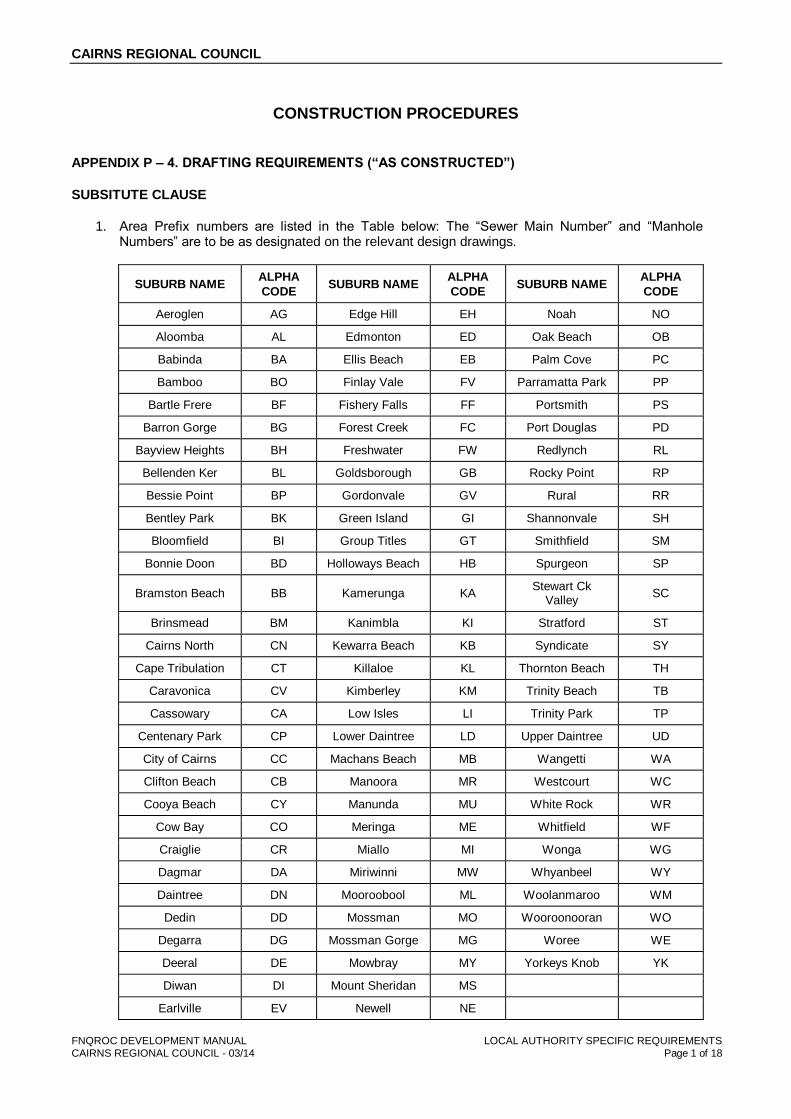
1. Area Prefix numbers are listed in the Table below: The “Sewer Main Number” and “Manhole Numbers” are to be as designated on the relevant design drawings.
SUBURB NAME ALPHA
CODE SUBURB NAME
ALPHA
CODE SUBURB NAME
ALPHA
CODE
Aeroglen AG Edge Hill EH Noah NO
Aloomba AL Edmonton ED Oak Beach OB
Babinda BA Ellis Beach EB Palm Cove PC
Bamboo BO Finlay Vale FV Parramatta Park PP
Bartle Frere BF Fishery Falls FF Portsmith PS
Barron Gorge BG Forest Creek FC Port Douglas PD
Bayview Heights BH Freshwater FW Redlynch RL
Bellenden Ker BL Goldsborough GB Rocky Point RP
Bessie Point BP Gordonvale GV Rural RR
Bentley Park BK Green Island GI Shannonvale SH
Bloomfield BI Group Titles GT Smithfield SM
Bonnie Doon BD Holloways Beach HB Spurgeon SP
Bramston Beach BB Kamerunga KA Stewart Ck
Valley SC
Brinsmead BM Kanimbla KI Stratford ST
Cairns North CN Kewarra Beach KB Syndicate SY
Cape Tribulation CT Killaloe KL Thornton Beach TH
Caravonica CV Kimberley KM Trinity Beach TB
Cassowary CA Low Isles LI Trinity Park TP
Centenary Park CP Lower Daintree LD Upper Daintree UD
City of Cairns CC Machans Beach MB Wangetti WA
Clifton Beach CB Manoora MR Westcourt WC
Cooya Beach CY Manunda MU White Rock WR
Cow Bay CO Meringa ME Whitfield WF
Craiglie CR Miallo MI Wonga WG
Dagmar DA Miriwinni MW Whyanbeel WY
Daintree DN Mooroobool ML Woolanmaroo WM
Dedin DD Mossman MO Wooroonooran WO
Degarra DG Mossman Gorge MG Woree WE
Deeral DE Mowbray MY Yorkeys Knob YK
Diwan DI Mount Sheridan MS
Earlville EV Newell NE
CAIRNS REGIONAL COUNCIL
FNQROC DEVELOPMENT MANUAL LOCAL AUTHORITY SPECIFIC REQUIREMENTS
CAIRNS REGIONAL COUNCIL - 03/14 Page 2 of 18
DESIGN GUIDELINE – D1 ROAD GEOMETRY
D1.22 SIGNS AND ROAD MARKINGS
SUBSTITUTE CLAUSE
Street signs installed within Cairns Regional Council are to be in accordance with CRC specific standard drawing S1040 – CRC.
DESIGN GUIDELINE – D2 SITE REGRADING
D2.05 CLEARING
ADDITTIONAL CLAUSES
8. Appropriate design includes the involvement of an AQF Level 5 certified Arborist to advise on the Tree Protection Zones and condition of trees which may be selected for possible retention.
9. Where trees are selected for retention, the Surveyor should include the size of the canopy and trunk diameter of the tree on the plan to scale. This will assist the Designer to determine the TPZ and SRZ as per AS4970 to avoid design conflicts with the trees.
10. As part of the clearing process and before any grading or other earthworks take place, Tree Protection Zones as per AS4970 are to be delineated and installed for those tree selected for retention.
DESIGN GUIDELINE - D3 ROAD PAVEMENTS
D3.14 ASPHALTIC CONCRETE
SUBSTITUTE CLAUSE
4. For all asphalt surfacing within Cairns Regional Council Local Authority, up to 30mm thickness, the asphalt grading defined as “CRC 10” shall be used. Refer to Appendix C for details
DESIGN GUIDELINE – D4 STORMWATER DRAINAGE
D4.05 DESIGN AVERAGE RECURRANCE INTERVAL
ADDITIONAL CLAUSES
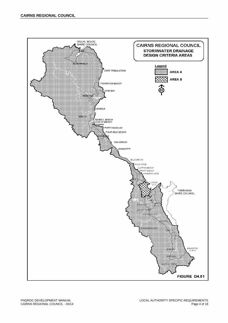
3. Due to the nature of the topography within and around Cairns City, varying design criteria have been developed for different areas.

CAIRNS REGIONAL COUNCIL
FNQROC DEVELOPMENT MANUAL LOCAL AUTHORITY SPECIFIC REQUIREMENTS
CAIRNS REGIONAL COUNCIL - 03/14 Page 3 of 18
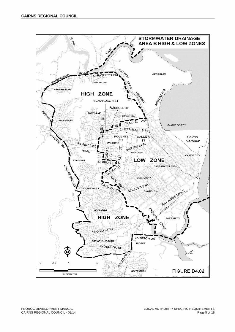
4. Figure D4.01 shows areas of the Cairns City where different design criteria apply. Area B generally relates to the historical developed area between the Whitfield Ranges and the Trinity Inlet where existing drainage systems are constrained by tidal influence. Area B is divided into the High Zone and Low Zone as indicated on Figure D4.02. Design criteria within the Area B (Low Zone) have been established to ensure that primary drainage systems are designed taking into account established tailwater levels as adopted by Cairns Regional Council. Tailwater levels for design of primary drainage systems within the Area B (Low Zone) area shall be as advised by the Council.
5. The design Annual Recurrence Intervals for all forms of development are as follows (these requirements shall apply in lieu of the requirements specified in Table 7.02 of the QUDM):
6. Within the Low Zone of Area B, Council will allow a minimum of 150mm freeboard from Habitable Floor levels to the 1 in 100 year ARI storm tide or flood event, whichever is the higher level. This level should be confirmed by Council prior to proceeding with any planning work. Within the High Zone of Area B, and the whole of Area A, the provisions of QUDM for freeboard are to apply.
AREA A – (Relates to all areas within Cairns Regional Council’s area of responsibility not
included in Area B – Refer Figure D4.01).
In accordance with Table 7.02.1 of the QUDM
AREA B (High Zone) – Refer Figure D4.02)
Major System Design – ARI 100 years. (Downstream emergency relief paths in low zone to be checked).
Minor System Design – ARI 5 years (with the exception of “Greenfield Sites”, that subject to Council approval may be ARI 2 year).
Cross Drainage - ARI 10 years for all roads.
AREA B (Low Zone – Refer Figure D4.02))
Major System Design - Surcharge paths for flows greater than ARI 5 years and overland flow paths shall be checked to ensure that flows do not enter private property, or cause local flooding and are conveyed to receiving water without causing damage to private property or municipal works.
Minor System Design - ARI 5 years
Cross Drainage - ARI 5 years for all roads.
6. Council will allow a minimum of 150 mm freeboard from Habitable Floor levels to the 1 in 100 year ARI storm tide flood event in accordance with Council's Flood Management Code.
CAIRNS REGIONAL COUNCIL
FNQROC DEVELOPMENT MANUAL LOCAL AUTHORITY SPECIFIC REQUIREMENTS
CAIRNS REGIONAL COUNCIL - 03/14 Page 4 of 18
CAIRNS REGIONAL COUNCIL
FNQROC DEVELOPMENT MANUAL LOCAL AUTHORITY SPECIFIC REQUIREMENTS
CAIRNS REGIONAL COUNCIL - 03/14 Page 5 of 18

CAIRNS REGIONAL COUNCIL
FNQROC DEVELOPMENT MANUAL LOCAL AUTHORITY SPECIFIC REQUIREMENTS
CAIRNS REGIONAL COUNCIL - 03/14 Page 6 of 18
DESIGN GUIDELINE - D6 WATER RETICULATION
D6.07 DESIGN CRITERIA
ADDITIONAL CLAUSE
8.4 Road Crossings under minor rural roads and low density residential roads or lessor shall be a minimum 63mm diameter where they service up to two dwellings, otherwise they must be a minimum 100mm diameter.
D6.17 TELEMETRY SYSTEMS
ADDITIONAL CLAUSE
2. SCADA telemetry for field outstations shall be in accordance with Council’s Field Outstation RTU Requirements. Refer Appendix B at the end of this section.
DESIGN GUIDELINE - D7 SEWERAGE
D7.13 PROPERTY CONNECTION
SUBSITUTE CLAUSE
1. All House Connection Branches (HCB’s) constructed within Cairns Regional Council shall be constructed in accordance with CRC standard drawing S3005 – CRC.
D7.25 TELEMETRY SYSTEMS
ADDITIONAL CLAUSE
2. SCADA telemetry for field outstations shall be in accordance with Council’s Field Outstation RTU Requirements. Refer Appendix B at the end of this section.
SPECIFICATION – S6 – SEWERAGE RETICULATION
S6.03 PIPES GENERAL
1. Alternative pipe material are permitted when registered on the Cairns Regional Councils Approved product list and installed to Manufactures Requirements and by a suitably qualified installer so as not to compromise product warranty.

CAIRNS REGIONAL COUNCIL
FNQROC DEVELOPMENT MANUAL LOCAL AUTHORITY SPECIFIC REQUIREMENTS
CAIRNS REGIONAL COUNCIL - 03/14 Page 7 of 18
S6.21 MANHOLES
2. Precast Manholes are not permitted without approval from council.
3. Alternative Manhole configuration to Drawing S3000 are permitted when registered on the Cairns Regional Councils Approved Product list and installed to Manufactures Requirement and by a suitably qualified installer so as not to compromise product warranty.
S6.23 Pump Stations
1. Alternative Sewerage Pump Station – Cast In Situ configurations to Drawing S3000 are permitted when registered on the Cairns Regional Councils Approved Product list and installed to Manufactures Requirement and by a suitably qualified installer so as not to compromise product warranty and RPEQ signed design drawings approved by Council.
CAIRNS REGIONAL COUNCIL STANDARD DRAWINGS
1. The following additional Standard Drawings, shall be deemed to be applicable for those works that shall ultimately become Cairns Regional Council’s responsibility for ongoing maintenance:
Roadwork’s & Drainage S1010C-CRC Public Utilities on Road Verges
S1020A-CRC Segmental Paving Units
S1040B-CRC Street Signage
Sewerage
S3035C CRC
S3036B CRC
S3037B CRC
S3038A CRC
S3039B CRC
Pump Station Overflow Pit Chamber and Outlet Details
Pump Station Overflow Pit Screen and Stopboard Details
Pump Station Overflow Pit Double Flap Valve
Pump Station Overflow Outlet Flap Valve
Pump Station Overflow Outlet Cage
Landscaping S4010A-CRC Typical Planting Plan & Plant Schedule
S4020A-CRC Typical Hard Landscape Plan
S4110A-CRC Landscaping Guidelines - Tree Grate Type 1
S4120A-CRC Landscaping Guidelines - Footpath Planter Type A
S4130A-CRC Landscaping Guidelines - Footpath Planter Type B
S4140A-CRC Landscaping Guidelines - Footpath Planter Type C
CAIRNS REGIONAL COUNCIL
FNQROC DEVELOPMENT MANUAL LOCAL AUTHORITY SPECIFIC REQUIREMENTS
CAIRNS REGIONAL COUNCIL - 03/14 Page 8 of 18
S4150A-CRC Landscaping Guidelines - Footpath Planter Type D
S4160A-CRC Landscaping Guidelines - Footpath Planter Type E
S4200A-CRC Verge Landscaping Guidelines - Tree Planting: Setout
S4210A-CRC Urban Street Tree Planting
S4220A-CRC Car Park Tree Planting
S4310B-CRC Landscaping Guidelines - Timber Bollard
Miscellaneous S9000A-CRC Water and Sewer Pump Station – Preferred Equipment List
S9004A-CRC Water and Sewer Pump Station – Generator Autochangeover Circuit
S9005A-CRC Water and Sewer Pump Station – Flow Meter Wiring
S9006A-CRC Water and Sewer Pump Station – Pump Control Switchboard Solar Shade To
Suit 1300mm Wide Switchboard
S9007A-CRC Water and Sewer Pump Station – - Pump Control Switchboard Solar Shade To
Suit 2150 Wide Switchboard
S9015A-CRC Levels Datum

CAIRNS REGIONAL COUNCIL
FNQROC DEVELOPMENT MANUAL LOCAL AUTHORITY SPECIFIC REQUIREMENTS
CAIRNS REGIONAL COUNCIL - 03/14 Page 9 of 18
APPENDIX A
DELETED
CAIRNS REGIONAL COUNCIL
FNQROC DEVELOPMENT MANUAL LOCAL AUTHORITY SPECIFIC REQUIREMENTS
CAIRNS REGIONAL COUNCIL - 03/14 Page 10 of 18
APPENDIX B
FIELD OUTSTATION RTU REQUIREMENTS
CAIRNS REGIONAL COUNCIL
FNQROC DEVELOPMENT MANUAL LOCAL AUTHORITY SPECIFIC REQUIREMENTS
CAIRNS REGIONAL COUNCIL - 03/14 Page 11 of 18
CRC Version 1878623-v2
Field Outstations
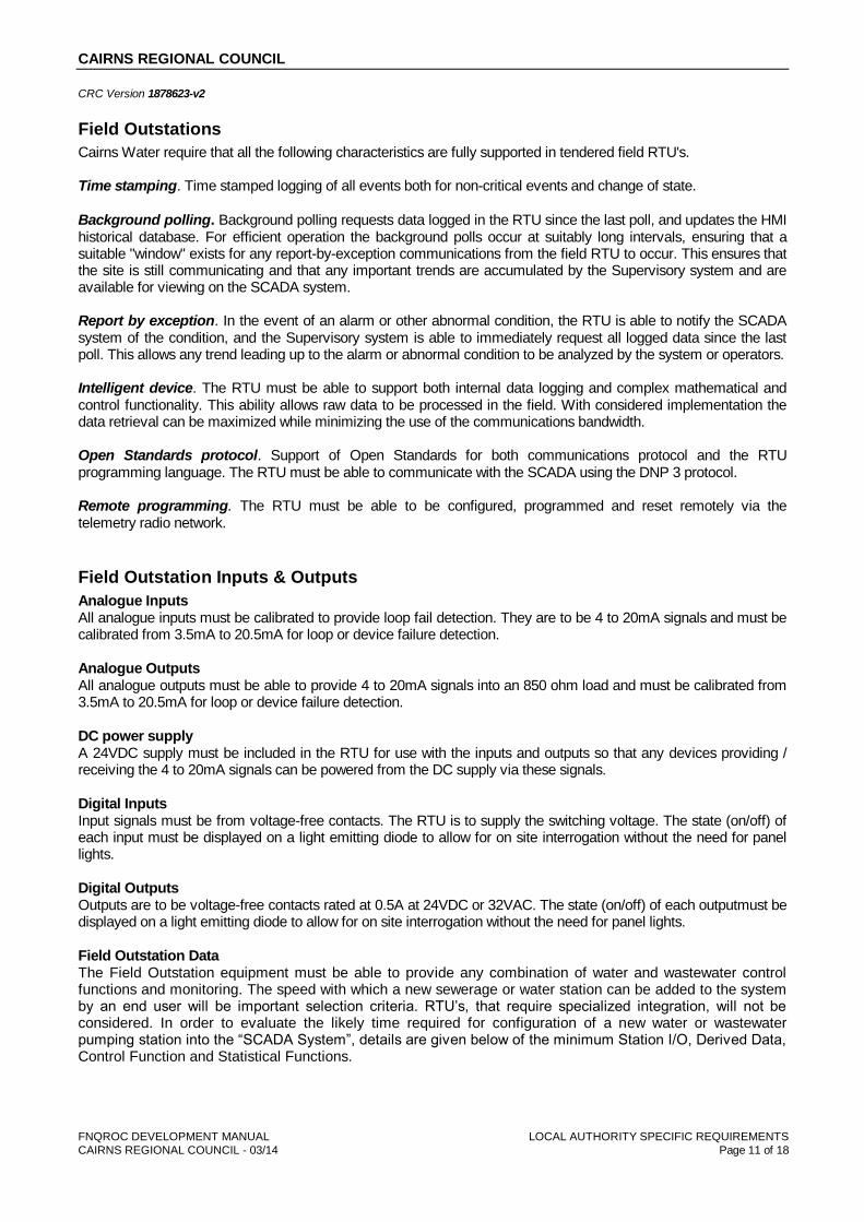
Cairns Water require that all the following characteristics are fully supported in tendered field RTU's. Time stamping. Time stamped logging of all events both for non-critical events and change of state. Background polling. Background polling requests data logged in the RTU since the last poll, and updates the HMI historical database. For efficient operation the background polls occur at suitably long intervals, ensuring that a suitable "window" exists for any report-by-exception communications from the field RTU to occur. This ensures that the site is still communicating and that any important trends are accumulated by the Supervisory system and are available for viewing on the SCADA system. Report by exception. In the event of an alarm or other abnormal condition, the RTU is able to notify the SCADA system of the condition, and the Supervisory system is able to immediately request all logged data since the last poll. This allows any trend leading up to the alarm or abnormal condition to be analyzed by the system or operators. Intelligent device. The RTU must be able to support both internal data logging and complex mathematical and control functionality. This ability allows raw data to be processed in the field. With considered implementation the data retrieval can be maximized while minimizing the use of the communications bandwidth. Open Standards protocol. Support of Open Standards for both communications protocol and the RTU programming language. The RTU must be able to communicate with the SCADA using the DNP 3 protocol. Remote programming. The RTU must be able to be configured, programmed and reset remotely via the telemetry radio network.
Field Outstation Inputs & Outputs
Analogue Inputs All analogue inputs must be calibrated to provide loop fail detection. They are to be 4 to 20mA signals and must be calibrated from 3.5mA to 20.5mA for loop or device failure detection. Analogue Outputs All analogue outputs must be able to provide 4 to 20mA signals into an 850 ohm load and must be calibrated from 3.5mA to 20.5mA for loop or device failure detection. DC power supply A 24VDC supply must be included in the RTU for use with the inputs and outputs so that any devices providing / receiving the 4 to 20mA signals can be powered from the DC supply via these signals. Digital Inputs Input signals must be from voltage-free contacts. The RTU is to supply the switching voltage. The state (on/off) of each input must be displayed on a light emitting diode to allow for on site interrogation without the need for panel lights. Digital Outputs Outputs are to be voltage-free contacts rated at 0.5A at 24VDC or 32VAC. The state (on/off) of each outputmust be displayed on a light emitting diode to allow for on site interrogation without the need for panel lights. Field Outstation Data The Field Outstation equipment must be able to provide any combination of water and wastewater control functions and monitoring. The speed with which a new sewerage or water station can be added to the system by an end user will be important selection criteria. RTU’s, that require specialized integration, will not be considered. In order to evaluate the likely time required for configuration of a new water or wastewater pumping station into the “SCADA System”, details are given below of the minimum Station I/O, Derived Data, Control Function and Statistical Functions.
CAIRNS REGIONAL COUNCIL
FNQROC DEVELOPMENT MANUAL LOCAL AUTHORITY SPECIFIC REQUIREMENTS
CAIRNS REGIONAL COUNCIL - 03/14 Page 12 of 18
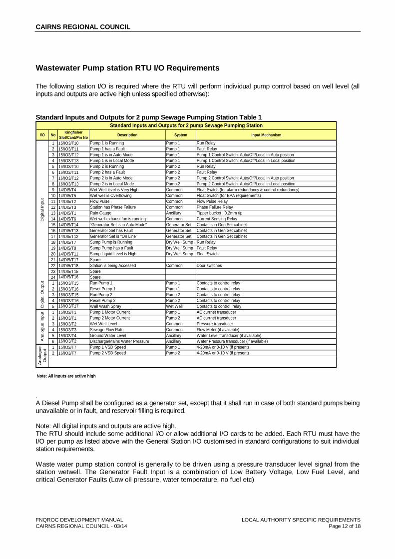
Wastewater Pump station RTU I/O Requirements
The following station I/O is required where the RTU will perform individual pump control based on well level (all inputs and outputs are active high unless specified otherwise):
Standard Inputs and Outputs for 2 pump Sewage Pumping Station Table 1
I/O NoKingfisher
Slot/Card/Pin NoDescription System Input Mechanism
1 15/IO3/T10 Pump 1 is Running Pump 1 Run Relay
2 15/IO3/T11 Pump 1 has a Fault Pump 1 Fault Relay
3 15/IO3/T12 Pump 1 is in Auto Mode Pump 1 Pump 1 Control Switch: Auto/Off/Local in Auto position
4 15/IO3/T13 Pump 1 is in Local Mode Pump 1 Pump 1 Control Switch: Auto/Off/Local in Local position
5 16/IO3/T10 Pump 2 is Running Pump 2 Run Relay
6 16/IO3/T11 Pump 2 has a Fault Pump 2 Fault Relay
7 16/IO3/T12 Pump 2 is in Auto Mode Pump 2 Pump 2 Control Switch: Auto/Off/Local in Auto position
8 16/IO3/T13 Pump 2 is in Local Mode Pump 2 Pump 2 Control Switch: Auto/Off/Local in Local position
9 14/DI5/T4 Wet Well level is Very High Common Float Switch (for alarm redundancy & control redundancy)
10 14/DI5/T5 Wet well is Overflowing Common Float Switch (for EPA requirements)
11 14/DI5/T2 Flow Pulse Common Flow Pulse Relay
12 14/DI5/T3 Station has Phase Failure Common Phase Failure Relay
13 14/DI5/T1 Rain Gauge Ancillary Tipper bucket , 0.2mm tip
14 14/DI5/T6 Wet well exhaust fan is running Common Current Sensing Relay
15 14/DI5/T14 "Generator Set is in Auto Mode" Generator Set Contacts in Gen Set cabinet
16 14/DI5/T13 Generator Set has Fault Generator Set Contacts in Gen Set cabinet
17 14/DI5/T12 Generator Set is "On Line" Generator Set Contacts in Gen Set cabinet
18 14/DI5/T7 Sump Pump is Running Dry Well Sump Run Relay
19 14/DI5/T8 Sump Pump has a Fault Dry Well Sump Fault Relay
20 14/DI5/T11 Sump Liquid Level is High Dry Well Sump Float Switch
21 14/DI5/T17 Spare
22 14/DI5/T18 Station is being Accessed Common Door switches
23 14/DI5/T15 Spare
24 14/DI5/T16 Spare
1 15/IO3/T15 Run Pump 1 Pump 1 Contacts to control relay
2 15/IO3/T16 Reset Pump 1 Pump 1 Contacts to control relay
3 16/IO3/T15 Run Pump 2 Pump 2 Contacts to control relay
4 16/IO3/T16 Reset Pump 2 Pump 2 Contacts to control relay
5 16/IO3/T17 Well Wash Spray Wet Well Contacts to control relay
1 15/IO3/T1 Pump 1 Motor Current Pump 1 AC currnet transducer
2 16/IO3/T1 Pump 2 Motor Current Pump 2 AC currnet transducer
3 15/IO3/T2 Wet Well Level Common Pressure transducer
4 15/IO3/T3 Sewage Flow Rate Common Flow Meter (if available)
5 15/IO3/T4 Ground Water Level Ancillary Water Level transducer (if available)
6 16/IO3/T2 Discharge/Mains Water Pressure Ancillary Water Pressure transducer (if available)
1 15/IO3/T7 Pump 1 VSD Speed Pump 1 4-20mA or 0-10 V (if present)
2 16/IO3/T7 Pump 2 VSD Speed Pump 2 4-20mA or 0-10 V (if present)
Note: All inputs are active high
Standard Inputs and Outputs for 2 pump Sewage Pumping Station
Dig
ita
l In
pu
tD
igita
l O
utp
ut
An
alo
gu
e I
npu
tA
nalo
gu
e
Ou
tpu
t
. A Diesel Pump shall be configured as a generator set, except that it shall run in case of both standard pumps being unavailable or in fault, and reservoir filling is required. Note: All digital inputs and outputs are active high. The RTU should include some additional I/O or allow additional I/O cards to be added. Each RTU must have the I/O per pump as listed above with the General Station I/O customised in standard configurations to suit individual station requirements. Waste water pump station control is generally to be driven using a pressure transducer level signal from the station wetwell. The Generator Fault Input is a combination of Low Battery Voltage, Low Fuel Level, and critical Generator Faults (Low oil pressure, water temperature, no fuel etc)

CAIRNS REGIONAL COUNCIL
FNQROC DEVELOPMENT MANUAL LOCAL AUTHORITY SPECIFIC REQUIREMENTS
CAIRNS REGIONAL COUNCIL - 03/14 Page 13 of 18
The RTU should include some additional I/O or allow additional I/O cards to be added. Each RTU must have the I/O per pump as listed above with the General Station I/O customized in standard configurations to suit individual station requirements. The RTU should include some additional I/O and/or allow additional I/O cards to be added. The RTU at every pumping station must calculate an estimate of flow from pump operations, given the well parameters. The current transmitters are used for determining possible pump choke or ragging. If the station current usage is outside a pre-determined band for “XX” seconds then this may indicate a pump ragging. Excessive current may mean a faulty bearing or similar, while a decrease in current may mean impeller damage or ragging of the impeller. Maximum & minimum allowed current set points are to be retained in the RTU for comparison and alarming. The value must be adjustable via the SCADA.
Wastewater Pump Station I/O between RTU and SCADA
The RTU is to perform calculations and station monitoring, based on set points and parameters adjustable via the SCADA. This allows standardization of the RTU programs, it allows flexibility of calculations, flexibility of alarming and of pump control duty and other functions. The modules within the RTU code for monitoring and calculating information based on optional devices such as a rain gauge and flow meter are to be enabled and disabled via the SCADA without the need to reprogram the RTU. Because the calculations are done in the RTU, accurate time stamped events are possible. All RTU data provided to the SCADA is to be time stamped in the RTU. Should the RTU lose connection with the SCADA, the RTU must store the events until they are later transferred to the SCADA database.
NOTES: All daily totalisation uses a rollover time of Midnight . A pump becomes unavailable when any of the following occur:
been reset by the SCADA
When a pump becomes unavailable, the other available pump(s) must take over the pumping duty automatically. The SCADA operator will use the Control points to override normal automatic operation of the station and individual pumps. The Analogue Set points are used to set station operating and alarm parameters. The RTU control program must be capable of the control functions and calculations indicated by the RTU I/O and RTU/SCADA I/O listed above. The adjustment of the setpoints is to be via SCADA. The adjustments must not require modification of the RTU’s control program.
CAIRNS REGIONAL COUNCIL
FNQROC DEVELOPMENT MANUAL LOCAL AUTHORITY SPECIFIC REQUIREMENTS
CAIRNS REGIONAL COUNCIL - 03/14 Page 14 of 18
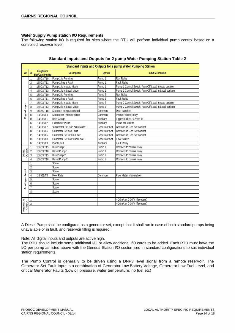
Water Supply Pump station I/O Requirements The following station I/O is required for sites where the RTU will perform individual pump control based on a controlled reservoir level:
Standard Inputs and Outputs for 2 pump Water Pumping Station Table 2
I/O NoKingfisher
Slot/Card/Pin NoDescription System Input Mechanism
1 15/IO3/T10 Pump 1 is Running Pump 1 Run Relay
2 15/IO3/T11 Pump 1 has a Fault Pump 1 Fault Relay
3 15/IO3/T12 Pump 1 is in Auto Mode Pump 1 Pump 1 Control Switch: Auto/Off/Local in Auto position
4 15/IO3/T13 Pump 1 is in Local Mode Pump 1 Pump 1 Control Switch: Auto/Off/Local in Local position
5 16/IO3/T10 Pump 2 is Running Pump 2 Run Relay
6 16/IO3/T11 Pump 2 has a Fault Pump 2 Fault Relay
7 16/IO3/T12 Pump 2 is in Auto Mode Pump 2 Pump 2 Control Switch: Auto/Off/Local in Auto position
8 16/IO3/T13 Pump 2 is in Local Mode Pump 2 Pump 2 Control Switch: Auto/Off/Local in Local position
9 14/DI5/T18 Station is being Accessed Common Door switches
10 14/DI5/T3 Station has Phase Failure Common Phase Failure Relay
11 14/DI5/T1 Rain Gauge Ancillary Tipper bucket , 0.2mm tip
12 14/DI5/T2 Flowmeter Pulse Ancillary Pulse per kilolitre
13 14/DI5/T7 "Generator Set is in Auto Mode" Generator Set Contacts in Gen Set cabinet
14 14/DI5/T6 Generator Set has Fault Generator Set Contacts in Gen Set cabinet
15 14/DI5/T5 Generator Set is "On Line" Generator Set Contacts in Gen Set cabinet
16 14/DI5/T8 Generator Set Low Fuel Level Generator Set Float Switch
17 14/DI5/T9 Plant Fault Ancillary Fault Relay
1 15/IO3/T15 Run Pump 1 Pump 1 Contacts to control relay
2 15/IO3/T16 Reset Pump 1 Pump 1 Contacts to control relay
3 16/IO3/T15 Run Pump 2 Pump 2 Contacts to control relay
4 16/IO3/T16 Reset Pump 2 Pump 2 Contacts to control relay
1 Spare
2 Spare
3 Spare
4 16/IO3/T4 Flow Rate Common Flow Meter (if available)
5 Spare
6 Spare
7 Spare
8 Spare
1 4-20mA or 0-10 V (if present)
2 4-20mA or 0-10 V (if present)
Standard Inputs and Outputs for 2 pump Water Pumping Station
Dig
ita
l In
pu
tD
igita
l
Ou
tpu
tA
na
logu
e I
npu
tA
na
logu
e
Ou
tpu
t
A Diesel Pump shall be configured as a generator set, except that it shall run in case of both standard pumps being unavailable or in fault, and reservoir filling is required. Note: All digital inputs and outputs are active high. The RTU should include some additional I/O or allow additional I/O cards to be added. Each RTU must have the I/O per pump as listed above with the General Station I/O customised in standard configurations to suit individual station requirements. The Pump Control is generally to be driven using a DNP3 level signal from a remote reservoir. The Generator Set Fault Input is a combination of Generator Low Battery Voltage, Generator Low Fuel Level, and critical Generator Faults (Low oil pressure, water temperature, no fuel etc)
CAIRNS REGIONAL COUNCIL
FNQROC DEVELOPMENT MANUAL LOCAL AUTHORITY SPECIFIC REQUIREMENTS
CAIRNS REGIONAL COUNCIL - 03/14 Page 15 of 18
Water Supply Pump Station I/O between RTU and SCADA
The RTU is to perform calculations and station monitoring, based on setpoints and parameters adjustable via the SCADA. This allows standardisation of the RTU programs, it allows flexibility of calculations, flexibility of alarming and of pump control duty and other functions. The modules within the RTU code for monitoring and calculating information based on optional devices such as a rain gauge and flow meter are to be enabled and disabled via the SCADA without the need to reprogram the RTU. Because the calculations are done in the RTU, accurate time stamped events are possible. All RTU data provided to the SCADA is to be time stamped in the RTU. Should the RTU lose connection with the SCADA, the RTU must store the events until they are later transferred to the SCADA database.
NOTES: All daily totalisation uses a rollover time of midnight . A pump becomes unavailable when any of the following occur:
When a pump becomes unavailable, the other available pump(s) must take over the pumping duty automatically. The SCADA operator will use the control points to override normal automatic operation of the station and individual pumps. The analogue Set points are used to set station operating and alarm parameters. The RTU control program must be capable of the control functions and calculations indicated by the RTU I/O and RTU/SCADA I/O listed above. The adjustment of the set points is to be via SCADA. The adjustments must not require modification of the RTU’s control program.
Standard RTU control functions for Wastewater and Water Supply pumping stations.
Well Level Control / Reservoir Level Control using SCADA adjustable set points for Duty Pump Start, Standby Pump Start & Pump Stop, and using the input from an analogue level transmitter or a reservoir level from a remote peer RTU at a reservoir. The RTU will activate a Pump Run Output when the well/reservoir level reaches the Duty Pump Start set point and deactivate the output when the level reaches the Pump Stop setpoint. The pump to be started will be determined by the duty control option selected. See below. Pump Duty Control with user selectable options for: CYCLE: where pump duty is swapped at the end of each pump cycle to ensure even run times of both pumps. DUTY 1-2: where Pump 1 is the duty pump & Pump 2 is standby. DUTY 2-1: where Pump 1 is the duty pump & Pump 2 is standby. Duty Level Override must be provided for testing purposes to allow the operator to start the station if it is between normal Start & Stop Levels. The station would start and run until the Stop level is reached and then return to normal operation. Maximum Permitted Pumps must be provided to allow the operator to specify how many pumps can run at one time. The Hydraulic Design of the station or the capacity of the electricity supply to the station will determine this. If the maximum permitted number of pumps is 1, it is assumed that one pump can cover all pumping requirements. If the duty pump is running and the well/reservoir level reaches the Standby Pump Start level, the Duty pump should stop and the Standby pump will start in its place as it is assumed that there may be a problem with the first pump. If the maximum permitted number of pumps is 2, it is assumed that in times of high flow that two (2) pumps will be required to run. The Standby Duty pump will start if the Standby Pump Start level is reached and both pumps will cut-out when the Pump Stop Level is reached. Station & Pump Inhibit - this option must be provided to allow the operator to inhibit a pump from running or the entire station for maintenance purposes. This command will generate some form of feedback to notify the operator that the station is inhibited.
CAIRNS REGIONAL COUNCIL
FNQROC DEVELOPMENT MANUAL LOCAL AUTHORITY SPECIFIC REQUIREMENTS
CAIRNS REGIONAL COUNCIL - 03/14 Page 16 of 18
Setpoint checks must be performed by the RTU program to confirm the validity of setpoints entered. This is to ensure that there is no logic error in the values entered. Default setpoints must also be provided within the RTU program to ensure that the program will operate when loaded for the first time without the need to enter setpoints. Pump Current Monitoring (SEWER SITES ONLY) must be implemented utilising a current transducers monitoring current of each pump. The program should compare the pump current against the Normal Pump Current setpoint and see whether it is above or below a tolerance setpoint. This must flag an alarm if the pump is running out of its rated range. It may also be an option to take some action within the program such as change pump duty. Optional Control Functions Reservoir Fill Control – reservoir should periodically send a refresh command to the pump station while it requests water, the pump station receiving the refresh command must start a watchdog timer that is reset by each refresh. If a refresh is not received within the watchdog period, the pump station RTU will stop pumping.
STANDARD STATISTICAL FUNCTIONS
All statistical functions are to work based on day running from midnight to midnight the next morning. This enables the various personnel to have the latest information available at the commencement of their work each day. Pump Starts Totalisation must count the Starts in the last hour as this relates to the capacity of the motor starter, which generally has a starts/hour rating. This Starts in the last hour figure should be compared with a Normal Starts setpoint and flag an alarm if exceeded. Values for Pump Starts Today & Yesterday must also be calculated. The value for yesterday will be uploaded to the SCADA for use in calculations to provide Weekly, Monthly & Annual figures. Pump Hours Run Totalisation must count the hours run since the pump has started. This Hours Run Since Start figure should be compared with a Normal Hours setpoint and flag an alarm if exceeded. This would come into play if there was a problem with the pump impeller or a faulty level transmitter where the well level failed to reach the Pump Stop setpoint. Values for Pump Hours Run Today & Yesterday must also be calculated. The value for yesterday can uploaded to the SCADA for use in calculations to provide Weekly, Monthly & Annual figures.
OPTIONAL STATISTICAL FUNCTIONS
Station Flow Totalisation should totalise the station inflow signal to provide total flow figures for Today &Yesterday. The value for yesterday can uploaded to the SCADA for use in calculations to provide Weekly, Monthly & Annual figures. It is preferred that the RTU totalise the raw count and apply a scaling factor at the SCADA. This is done to keep program generic and suitable for any flow meter scaling.
Water Supply Reservoir I/O Requirements
The reservoir I/O required for sites will depend upon proposal, contact Cairns Regional Council, Water & Waste SCADA Co-ordinator for requirements.
Water Supply Multiple Booster Pressure Pump Station I/O Requirements
The Booster Pressure Pump Station I/O required for sites will depend upon proposal, contact Cairns Regional Council, Water & Waste SCADA Co-ordinator for requirements.
CAIRNS REGIONAL COUNCIL
FNQROC DEVELOPMENT MANUAL LOCAL AUTHORITY SPECIFIC REQUIREMENTS
CAIRNS REGIONAL COUNCIL - 03/14 Page 17 of 18
APPENDIX C
ASPHALT SPECIFICATION
“CRC 10”
CAIRNS REGIONAL COUNCIL
FNQROC DEVELOPMENT MANUAL LOCAL AUTHORITY SPECIFIC REQUIREMENTS
CAIRNS REGIONAL COUNCIL - 03/14 Page 18 of 18
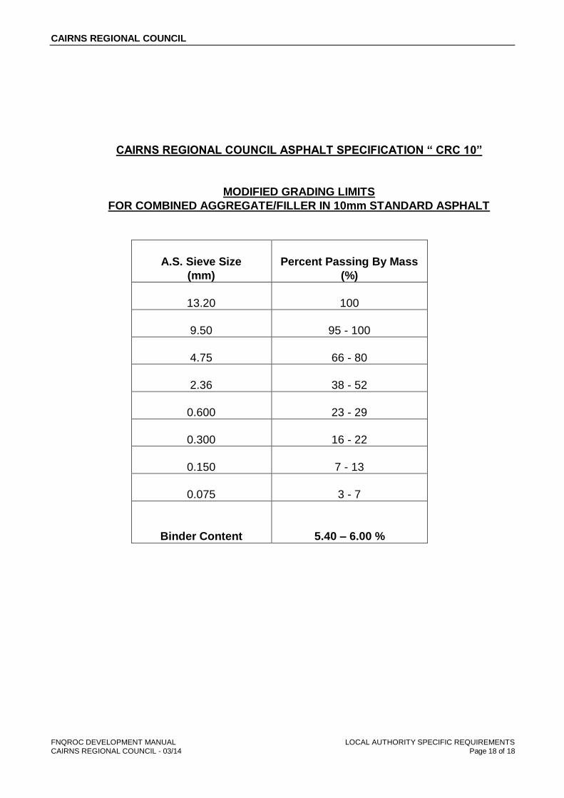
CAIRNS REGIONAL COUNCIL ASPHALT SPECIFICATION “ CRC 10”
MODIFIED GRADING LIMITS
FOR COMBINED AGGREGATE/FILLER IN 10mm STANDARD ASPHALT
A.S. Sieve Size
(mm)
Percent Passing By Mass
(%)
13.20
100
9.50
95 - 100
4.75
66 - 80
2.36
38 - 52
0.600
23 - 29
0.300
16 - 22
0.150
7 - 13
0.075
3 - 7
Binder Content
5.40 – 6.00 %


![Welcome! [ww1.jeppesen.com]€¢ Create a tail sign specific MEL (and have it approved by the Competent Authority) • Apply for specific approvals (e.g. RVSM, LVO) The fulfillment](https://static.fdocuments.net/doc/165x107/5b0551427f8b9a5c308b6e15/welcome-ww1-create-a-tail-sign-specific-mel-and-have-it-approved-by-the.jpg)

