![Screen-Space Ambient Occlusion Using A-buffer Techniques · 2016. 6. 20. · Screen-Space Ambient Occlusion covers methods and algorithms to solve the occlusion integral [11] in screen-space](https://static.fdocuments.net/doc/165x107/609e6b13e6da415d6858b680/screen-space-ambient-occlusion-using-a-buffer-techniques-2016-6-20-screen-space.jpg)
Local Ambient Occlusion in Direct Volume Rendering
13
Linköping University Post Print Local Ambient Occlusion in Direct Volume Rendering Frida Hernell, Patric Ljung and Anders Ynnerman N.B.: When citing this work, cite the original article. ©2009 IEEE. Personal use of this material is permitted. However, permission to reprint/republish this material for advertising or promotional purposes or for creating new collective works for resale or redistribution to servers or lists, or to reuse any copyrighted component of this work in other works must be obtained from the IEEE. Frida Hernell, Patric Ljung and Anders Ynnerman, Local Ambient Occlusion in Direct Volume Rendering, 2010, IEEE TRANSACTIONS ON VISUALIZATION AND COMPUTER GRAPHICS, (16), 4, 548-559. http://dx.doi.org/10.1109/TVCG.2009.45 Postprint available at: Linköping University Electronic Press http://urn.kb.se/resolve?urn=urn:nbn:se:liu:diva-56687
Transcript of Local Ambient Occlusion in Direct Volume Rendering
Linköping University Post Print
Local Ambient Occlusion in Direct Volume
Rendering
Frida Hernell, Patric Ljung and Anders Ynnerman
N.B.: When citing this work, cite the original article.
©2009 IEEE. Personal use of this material is permitted. However, permission to
reprint/republish this material for advertising or promotional purposes or for creating new
collective works for resale or redistribution to servers or lists, or to reuse any copyrighted
component of this work in other works must be obtained from the IEEE.
Frida Hernell, Patric Ljung and Anders Ynnerman, Local Ambient Occlusion in Direct
Volume Rendering, 2010, IEEE TRANSACTIONS ON VISUALIZATION AND
COMPUTER GRAPHICS, (16), 4, 548-559.
http://dx.doi.org/10.1109/TVCG.2009.45
Postprint available at: Linköping University Electronic Press
http://urn.kb.se/resolve?urn=urn:nbn:se:liu:diva-56687

Local Ambient Occlusion in DirectVolume Rendering
Frida Hernell, Patric Ljung, Member, IEEE Computer Society, and Anders Ynnerman, Member, IEEE
Abstract—This paper presents a novel technique to efficiently compute illumination for Direct Volume Rendering using a localapproximation of ambient occlusion to integrate the intensity of incident light for each voxel. An advantage with this local approach isthat fully shadowed regions are avoided, a desirable feature in many applications of volume rendering such as medical visualization.Additional transfer function interactions are also presented, for instance, to highlight specific structures with luminous tissue effects andcreate an improved context for semitransparent tissues with a separate absorption control for the illumination settings. Multiresolutionvolume management and GPU-based computation are used to accelerate the calculations and support large data sets. The schemeyields interactive frame rates with an adaptive sampling approach for incrementally refined illumination under arbitrary transfer functionchanges. The illumination effects can give a better understanding of the shape and density of tissues and so has the potential toincrease the diagnostic value of medical volume rendering. Since the proposed method is gradient-free, it is especially beneficial at theborders of clip planes, where gradients are undefined, and for noisy data sets.
Index Terms—Local illumination, volumetric ambient occlusion, volume rendering, medical visualization, emissive tissues, shading,
shadowing.
Ç
1 INTRODUCTION
INTERACTION with patient-specific Computed Tomography(CT) data through Direct Volume Rendering (DVR) has
become an invaluable tool in medical diagnosis andcontributed to the spread of radiological methodologiesinto several areas of medical practice, such as postmortemimaging [1] and preoperative planning [2], [3], [4], [5]. Tofurther promote the use of DVR in medicine, newtechniques for enhanced perception of shapes and densities,ensuring a more confident diagnosis, are needed. One areaof development that shows promise in supporting this is theinclusion of more sophisticated lighting models thatprovide visual cues to improve the perception of shapesand depth. Langer and Bulthoff [6] found that ambientlighting in particular, like lighting on a cloudy day,significantly enhances the ability of humans to distinguishobjects and their properties.
A commonly used lighting approximation in volumerendering applications is the Phong shading model [7], orlater, the Blinn-Phong model [8]. This approach is suitablefor direct volume rendering since it can be evaluated atinteractive frame rates. The method does, however, makeuse of the normalized gradient of the volume scalar field,which limits its applicability. If, for instance, the scalar dataare noisy, then the gradients become indistinct. Anotherproblem is that the gradients are only well defined at sharp
transitions between different scalar values, which meansthat light values can be estimated for surfaces but not aseasily for homogeneous regions. It is, therefore, moredifficult to define a light approximation in semitransparentregions and at clip plane surfaces.
More advanced lighting models, like global illumination,are computationally expensive and cannot readily be usedin interactive DVR. A further disadvantage of such models,in the context of medical visualization, is that regions can beshadowed by dense objects occluding the light. The skull,for example, can occlude the light such that a tumor or otherfeature may not be illuminated and so cannot be identified.
This paper proposes a new shading model in DVR, LocalAmbient Occlusion (LAO), that considers shadowing bystructures in the vicinity of each voxel. It can be used insteadof, or as a complement to, diffuse shading. The methodcomputes the incident light for each voxel by sampling aspherical neighborhood around each voxel, capturingshadows and light emissions locally. This light informationis then used in the rendering pass as the ambient light termin the volume rendering integral. Since the method isgradient-free, it is also less sensitive to noise and homo-geneous regions with poorly defined gradients. As anintegrated part of the LAO approach, illumination fromemissive tissues is also included and by using adjustedopacities in the LAO calculation, structures and features canalso be made more prominent, providing more contrast, inhighly transparent regions.
The main contributions of this paper are the following:
. introduction of Local Ambient Occlusion as a newshading model in direct volume rendering;
. a method for interactive transfer function-basedemission that improves the visibility of user-specified data ranges;
. an adaptive sampling scheme achieving highquality light approximation while optimizing thenumber of samples;
548 IEEE TRANSACTIONS ON VISUALIZATION AND COMPUTER GRAPHICS, VOL. 16, NO. 4, JULY/AUGUST 2010
. F. Hernell and A. Ynnerman are with the Department of VisualInformation Technology and Applications (VITA) and the Center forMedical Image Science and Visualization (CMIV), Linkoping University,Universitet Campus Norrkoping 601 74, NORRKOPING, Sweden.E-mail: {frihe, andyn}@itn.liu.se.
. P. Ljung is with Siemens Corporate Research, 755 College Rd East,Princeton, NJ 08540-6632. E-mail: [email protected].
Manuscript received 21 Jan. 2008; revised 13 Jan. 2009; accepted 4 Mar. 2009;published online 17 Apr. 2009.Recommended for acceptance by H.-C. Hege, D.H. Laidlaw, and R. Machiraju.For information on obtaining reprints of this article, please send e-mail to:[email protected], and reference IEEECS Log NumberTVCGSI-2008-01-0100.Digital Object Identifier no. 10.1109/TVCG.2009.45.
1077-2626/10/$26.00 � 2010 IEEE Published by the IEEE Computer Society
Authorized licensed use limited to: Linkoping Universitetsbibliotek. Downloaded on May 31,2010 at 10:36:57 UTC from IEEE Xplore. Restrictions apply.
. an additional transfer function for control of theamount of light absorbed by different tissue types inLAO to increase the preserved context of near-transparent tissues; and
. an alternate method enhancing shape perception atclip planes.
Despite the limited neighborhood region, estimation ofLAO is computationally demanding since it must beevaluated for each voxel. A multiresolution framework is,therefore, used to reduce the amount of computation inempty or homogeneous spaces and interactivity is thenmaintained during the LAO calculation. Furthermore, sincethe ambient occlusion is view-independent, a reestimationof the integrated light intensities need only be performedwhen the transfer function is modified.
2 RELATED WORK
A large number of methods have been proposed forgeneration of realistic illumination in computer graphics [9],[10]. Computing self-shadowing in volume rendering is acomputationally demanding problem and several approx-imation schemes have been proposed to achieve interactiveframe rates. One approach is to preprocess the lightcomputation and store the intensities in a shadow map, seeBehrens and Ratering [11] and Hadwiger et al. [12], forexample. This shadow map must, however, be reestimatedeach time the transfer function or lightcondition changes. Ifanupdate of the light map takes too long, it could cause problemsin clinical situations, where fine-tuning of the transferfunction (TF) is needed. Another approach, presented byKniss et al. [13], estimates the shadows in parallel with thefinal volume rendering that is carried out using half-angletexture slicing. The half angle refers to the angle betweenthe light direction and the view direction. This method alsoincludes scattering and color bleeding effects. The method,however, relies on rendering based on texture slicing andsupports only a single light source. A variation of this methodthat takes several samples in the 2D shadow buffer of eachslice to create dilated shadows in the light direction waspresented by Desgranges et al. [14]. The estimated shadowvalue of a voxel is, in this approach, the minimum value of theneighboring shadow values that also gives an effect ofattenuation of light within an object. This method isgradient-free but is also still limited to a single light source.
The local volumetric shadowing effect presented in thispaper is an extension of our earlier work [15] andcomparable with ambient occlusion for surfaces, which isa simplification of the obscurance illumination model [16],[17], where incident light at a surface element is estimatedby integrating the visibility over a hemisphere.
A number of methods have been presented for surfacerendered ambient occlusion, for example, [18], [19], [20], [21].One of these is vicinity shading, presented by Stewart [19],who modified the rendering equation presented by Kajiya[22] to yield an illumination model that, for each surfacepoint, estimates the light that arrives from a large number ofdirections. One downside of this method is long preproces-sing times. Tarini et al. [18] subsequently refined this modelto increase the performance. Wyman et al. [23] used acombination of Monte Carlo path tracing and a sphericalharmonic representation to approximate the irradiance overa hemisphere and allow dynamic environmental lighting. A
combination of a low frequency model of the geometry andthe original geometry was used by Shanmugam and Arikan[20] for a better approximation of the ambient lighting.
Methods for ambient occlusion are often referred to as“all-or-nothing” methods, which means that there is noconsideration of transparency. Incident light on any voxelfrom a direction is blocked by any voxel having a highervalue along that direction. When generalizing thesemethods to take participating media into account, caremust be taken to reduce the complexity introduced bylarge regions of semitransparent voxels. A method forcombining ambient occlusion computed for isosurfaces andsubsurface scattering effects was recently proposed byRezk-Salama [24].
A problem with many illumination methods is to createaccurate shadowing at clipping surfaces. Wieskopf et al.[25] proposed an optical model to merge surface andvolume-based illumination to achieve a consistent shadingof the clipping surface. However, the accuracy of thismethod suffers from inaccurate reconstruction of gradients.
This paper also presents rendering with luminous effectsfor the purpose of highlighting tissues. Previous examplesof luminous volumes can be found in rendering ofastrophysical simulations as shown by Magnor et al. [26]and Kahler et al. [27]. In their work, the emittance isestimated from physical properties such as temperature andgas density. In most cases, the luminosity of the volume isprecomputed and gives a static contribution to theillumination. Halo effects, as proposed by Svakhine andEbert [28] and Bruckner and Groller [29], are otherproposed approaches for highlighting tissues in volumerendering. A further effect that the TF interactions in ourpresented methods bring is enhanced context in renderingsof near-transparent tissues. Some methods have beenproposed in previous work for context preserving visuali-zation, for instance, by Bruckner et al. [30].
3 VOLUMETRIC AMBIENT OCCLUSION
The introduced LAO shading model generalizes theambient lighting term typically found in shading computa-tions. As a starting point, the traditional volume renderingintegral, as expressed by Max [31], is revisited,
IðDÞ ¼ I0 � e�R D
0�ðtÞdt þ
Z D
0
gðsÞ � e�R D
s�ðtÞdt
ds; ð1Þ
where the first term represents the light coming from thebackground I0, attenuated with the optical depth, the integralof the extinction coefficient � , and the second term representsthe integration of attenuated light contributions gðsÞ, for eachlocation s, along the ray. Equation (1) represents theraycasting method used to render a volumetric image. Inthis paper, this process is referred as the rendering pass, andfor clarity, the formulation of g in the rendering pass will bedenoted by gR. A closer look at the light contribution termgRðsÞ traditionally reveals three components,
gRðsÞ ¼ AðsÞ þ kdðLL �NNÞcðsÞ þ ksðNN �HHÞpcðsÞ; ð2Þ
where AðsÞ is the ambient light contribution, typicallyrepresented by a constant factor, as in kacðsÞ. The colorclassification of each sample is represented by cðsÞ. The
HERNELL ET AL.: LOCAL AMBIENT OCCLUSION IN DIRECT VOLUME RENDERING 549
Authorized licensed use limited to: Linkoping Universitetsbibliotek. Downloaded on May 31,2010 at 10:36:57 UTC from IEEE Xplore. Restrictions apply.

second term represents the diffuse lighting and the thirdadds specular highlights based on the half-angle techniqueby Blinn [8].
Local Ambient Occlusion is a way to enhance the ambientterm A such that shadows and light emission from localfeatures are included. Equation (1) is used again but, insteadof calculating the light reaching a pixel in the framebufferfor the final image, it is used to compute the incident lightarriving at a voxel location x. LAO furthermore onlyconsiders a local neighborhood, a sphere centered at x. Thisserves two purposes: it both reduces the computationaldemand and avoids global shadows that might hiderelevant information. This approach allows for interactiveframe rates and yet produces sufficient shadow effects.
Equation (1) is reformulated to originate at the voxellocation x, integrating the lighting contribution along raysenumerated k. The direction of integration is also changedsuch that the origin is at the voxel center and D ¼ R�, theradius of the spherical neighborhood �.
AkðxÞ ¼Z R�
a
gAðsÞ � e�R s
a�ðtÞdt
ds; ð3Þ
where a is a small offset to avoid self-occlusion of the voxelat location x and gAðsÞ is used to denote the special lightcontribution for LAO. This formulation allows incorporationof semitransparency, as compared to previous all-or-nothingapproaches, and by accumulating several directions dis-tributed over the sphere, a Local Ambient Occlusion schemeis achieved. The formulation of gAðsÞ is explained next.
3.1 Light Integration
As an initial approach, light could be considered to beincident on the sphere boundary only. This yields aformulation of gAðsÞ as
gAðsÞ ¼ �ðs�R�Þ; ð4Þ
where � is the Dirac delta, ensuring only light contribution atthe boundary of the neighborhood �. This approach yieldssharp shadow boundaries as soon as any occluder intersectsthe sphere, see Fig. 1. To avoid this appearance, a significantnumber of rays must be traced to sufficiently smooth theambient lighting. Instead, the ambient light source can beconsidered volumetric, adding a fractional light emission ateach sample point. With the same number of integrated rays,
in this case 8, the shadows become significantly smoother, asshown in Fig. 1. The formulation of gAðsÞ is here
gAðsÞ ¼1
R� � að5Þ
for a distribution of light along the ray.Basic numerical evaluation of the integral in (3) in a
front-to-back compositing scheme is simply expressed as
AkðxÞ ¼1
M
XMm¼1
gmYm�1
i¼1
ð1� �iÞ; ð6Þ
where gm, the discretized version of gAðsÞ, represents thelight contribution at sample point m along the ray. Since thescaling factor 1=M is moved outside the sum, gm is simplyequal to 1. �i is the representation of the opacity at sampleposition i, according to the current TF.
The combined local ambient occlusion AðxÞ for a voxel atx is then given by the normalized sum of all incident lightrays AkðxÞ:
AðxÞ ¼ 1
K
XKk¼1
wkAkðxÞ: ð7Þ
Each direction is also associated with a weight wk to allowfor directional weighting of the ambient light. RecomputingAðxÞ is only required when the TF changes, when adifferent directional weighting is desired, or when thecropping of the volume is changed.
3.2 Emissive Materials and TF Variations
After establishing the basic formulation of LAO, it ispossible to explore different variations of gAðsÞ. In thiswork, additional TFs and variations of the original TF havebeen used.
An additional TF is added representing the coloremission, based on user-defined tissue and material densityranges, or simply TF primitives such as trapezoids orpolygon envelopes. This emission component is denoted bycEðsÞ and (5) is then extended to
gAðsÞ ¼1
R� � aþ cEðsÞ: ð8Þ
The emission can be implemented as a separate TF orderived from the basic TF by specifying a glow/emissionfactor for a TF primitive or range. This simulates single lightscattering of luminous objects within the volume. For thefull effect, the emission must also be included during therendering pass. The synthetic data set used in Figs. 1 and 5also contains subsurface layers of material, which can bemade emissive with an appropriate TF selection. The resultis shown in Fig. 6 and further discussed in Section 5.
In volume rendering visualizations, it can furthermore bebeneficial to set a low opacity for some tissue types in order toexplore inner structures while a global context is preserved.However, LAO-illuminated tissues of low densities have ahomogeneous appearance with weak contrasts betweenshadowed and unshadowed regions since each sample pointhas a very low impact on the light attenuation. By allowingthe user to use a separate control for the absorption in LAO,different from the one used in the rendering pass, shadow
550 IEEE TRANSACTIONS ON VISUALIZATION AND COMPUTER GRAPHICS, VOL. 16, NO. 4, JULY/AUGUST 2010
Fig. 1. Comparison between (a) boundary light contribution and
(b) volumetric light contribution. Boundary contribution causes hard
shadow edges that are avoided by the volumetric light contribution.
Authorized licensed use limited to: Linkoping Universitetsbibliotek. Downloaded on May 31,2010 at 10:36:57 UTC from IEEE Xplore. Restrictions apply.

contrast can be increased for low-opacity regions. This issimply achieved by using a different lookup table for �i in (6)or a different TF ��ðsÞ ¼ ��AðsÞ in (3).
4 IMPLEMENTATION
As can be noted from the equations above, LAO computa-tion is driven by the processing of each voxel in the volume.An implementation using fully sampled regular linearvolumes is, therefore, fairly straightforward. It is, however,unnecessary to compute detailed illumination in emptyspace or homogeneous areas, as defined by the TF.Superfluous sampling in those regions can be avoided byemploying a multiresolution approach. Such an approachcan remove empty blocks and select lower resolutions forhomogeneous regions. In this implementation, a flatblocking multiresolution method is used, as presented byLjung et al. [32], [33] and Ljung [34], which allows for agraceful data reduction using the TF to optimize theresulting image quality. For completeness of this paper, asummary of flat blocking data management is provided.Some additional data structures and constraints arerequired, described below in detail, to apply the LAOmethod within the multiresolution framework.
4.1 Multiresolution Processing
In a preprocessing stage, a regular linear volume is dividedinto small blocks of typically 163 voxels, each block is encodedwith all levels of detail, that is, 83; 43; 23; 13 voxels. Theseblocks are organized into a multiresolution representationenabling efficient loading of arbitrary LOD selection atruntime. The LOD selection is updated when the TF ischanged or the volume is cropped. The resolution of eachblock is chosen according to an optimization process based onthe blocks’ content in the TF domain, i.e., the data distributionmapped through the TF, which optimizes the resulting imagequality given a user- or system-defined memory limit. Thescheme will prioritize blocks showing high variation in the TFdomain, blocks of medium to low variation are given lowerpriority, and empty blocks can be skipped completely. In ourimplementation, the minimum and maximum LOD fornonempty blocks can be set with a separate LOD for emptyblocks. Empty blocks can also be skipped.
The volume data in the LOD selection are packed into asingle 3D texture, similar to the approach by Kraus and Ertl[35], but without any boundary voxel replication since aninterblock interpolation technique is applied when re-quired, see Ljung et al. [33] for details. The translation ofvolume coordinates V to the packed texture coordinates P
is facilitated by a forward mapping index texture. Thistexture has the same size as the number of blocks in threedimensions and contains the 3D offset and the size of eachblock. In order to do the reverse translation, a reversemapping index texture is also required. Since a single voxelin the packed volume texture can cover an entire block, thisreverse mapping index texture would have to be of thesame size as the packed volume. In practice, however, it isoften sufficient to restrict the minimum LOD for nonemptyblocks to 43 voxels, and thus, allow the reverse indextexture to be 64 times smaller.
4.2 LAO Pipeline
The per-fragment pipeline processing is illustrated in Fig. 2.A 3D texture is created to hold the emissive color and theambient light of each voxel. The entire volume is thenprocessed by mapping all the slices one by one as a renderingtarget of a framebuffer object. In each pass, one or more raydirections can be processed, triggered by rendering a quadover the entire framebuffer, where each pixel maps to onevoxel in the mapped 3D texture. The 3D illumination texturehas the same dimensions as the packed volume texture andthe same multiresolution layout is used. Since the processingis driven by the multiresolution layout, the data reductionachieved by the LOD selection, thus, directly implies aperformance gain in the LAO computation.
Estimation of the volumetric LAO is performed incre-mentally, updating one ray direction per frame and storingthe accumulated result in an ambient light texture usingthe OpenGL blend operation. The progressive update ofthe ambient intensity texture, as defined by (7), isreformulated as
Ak ¼ 1
k�Ak þ 1� 1
k
� ��Ak�1; ð9Þ
where Ak is the accumulated intensity after k ray directions,with A0 ¼ 0. The blend operation adds a fraction of theintensity Ak from ray direction k. The number of raydirections K to sample can dynamically be configured andthe directions are stored in a texture together with thedirectional weight wk. Ray directions are created bysubdividing either a tetrahedron, icosahedron, or octahe-dron to different levels, depending on the desired numberof rays, as in Tarini et al. [18]. These shapes generateuniform distributions of ray directions.
Once all directions are processed, the final ambient lightintensity volume is used in the rendering pass. In thecurrent implementation, the rendering is interleaved with
HERNELL ET AL.: LOCAL AMBIENT OCCLUSION IN DIRECT VOLUME RENDERING 551
Fig. 2. Per-fragment computations to evaluate LAO for a voxel. The packed coordinates (P) are transformed into volume coordinates (V) through an
index texture. Rays are generated to sample the volume around the voxel. For each sample, the reverse index texture gives locations in the packed
volume to retrieve scalar data. The final fragment intensity is the average of the incrementally processed ray intensities.
Authorized licensed use limited to: Linkoping Universitetsbibliotek. Downloaded on May 31,2010 at 10:36:57 UTC from IEEE Xplore. Restrictions apply.

the intensity texture updates, thus allowing user interac-tion although all ray directions may require several framesto complete.
Using the location of the fragment in the framebufferplus the current slice z-offset, as illustrated in Fig. 2, thereverse index map P ! V is used to determine the voxellocation in volume coordinates. The ray integral is thencomputed for one or more directions. One direction perpass is commonly used to provide a higher degree ofinteractivity. In the integration, each sample requires atexture indirection from volume coordinates to packedtexture coordinates to which end the forward mappingindex texture V ! P is used.
The rendering of the volume image is performed withraycasting using adaptive sampling, as presented by Ljung[34]. This techniqueuses the scale of eachblockto dynamicallyadapt the sampling ratio per block, and thus, effectivelyachieves a speedup of the order of the cube root of the datareduction ratio, the schemeis, thus,capable of skippingemptyspace at the front and back of the volume as well as any emptyspace within the volume. To provide a continuous scalar fieldfrom the multiresolution volume, an interblock interpolationtechnique is used [33]. This approach does not require anyvoxel replication from neighboring blocks and also supportsarbitrary resolution differences. This interpolation scheme isapplied when the user stops interacting with the volume. Inmany cases, the discontinuity artifacts are minor and dependon the current TF. Interblock interpolation is, however, notconsidered in the LAO computations, since it would requiretoo many texture lookups. Only minor artifacts have beenobserved due to this limitation.
4.3 Local Ambient Occlusion Sampling
The performance of LAO computations can be improved byadjusting the sampling density along rays for voxels inlower resolution blocks. There are different ways ofadjusting the sampling density and the simplest approachis to adjust the sampling rate relative to the sampling densityof the underlying volume data, as illustrated in Fig. 3a. For aray originating in a block of scale ��, the step length isadjusted with ��max=�� for all samples along that ray. Themaximum resolution ��max yields the highest samplingdensity, given the base sampling density ��B. This may,however, lead to artifacts since low-resolution blocks canmiss occluding features in neighboring blocks of higher
resolution due to the undersampling while a neighboringblock of lower resolution is highly oversampled. By employ-ing an adaptive sampling density based on the sampledblocks resolution ��i at sample location i along the ray, theseartifacts are reduced. This ensures that features are notmissed, given that a sufficient base sampling density is used.Fig. 3b illustrates this adaptive sampling strategy. A caveatis the crossing of block boundaries in which the schememust ensure that the density is properly adjusted whenentering a new block. In the stepping along the ray, the nextposition is set to the first discrete location, according to thebase sampling density, which falls inside the next block [34].This approach is also used in the rendering pass.
In order to maintain a consistent light contribution forthe continuous volumetric light used in LAO, it is importantthat each ray has a unit contribution. Since an adaptivesampling scheme is used, the light contribution li at eachsample point i must also be adaptive. This is solved bydetermining the light intensity based on the step sizesbetween the current sample locations. Fig. 4 illustrates anLAO ray with adaptive sampling and a few cases of theadded light contribution for l1; l3, and lm. The followingequation describes the calculation of the light contributionfor each sample point:
li ¼�si
R� � a; �si ¼
�12 ; if i ¼ 1;
�i�1 þ�i2 ; if 1 < i < m;
�i�12 þ�m; if i ¼ m:
8>><>>:
ð10Þ
With adaptive sampling density, the opacities and colorshave to be corrected as well, which is traditionally doneusing the opacity correction equation, below, where �0 is theadjusted opacity. �s represents the sample’s extent asdefined in (10). In addition, a parameter � is introduced tofurther control the appearance of LAO:
�0 ¼ 1:0� ð1:0� �Þ��s�B : ð11Þ
The contribution of emissive light also depends on theextent of the samples and is adjusted according to
c0EðsÞ ¼�s
��BcEðsÞ: ð12Þ
4.4 Clip Plane Interactionin LAO-Illuminated Volumes
Gradient-based shading, such as diffuse illumination, iscommonly used when interacting with clip planes in medicalvisualization. Although the diffuse shading technique is fast,
552 IEEE TRANSACTIONS ON VISUALIZATION AND COMPUTER GRAPHICS, VOL. 16, NO. 4, JULY/AUGUST 2010
Fig. 3. Important structures can be missed when using a sampling
density fixed to the LOD in the originating block (a). A more suitable
sampling is performed with adaptive step lengths in (b), which optimizes
the number of steps. Samples are marked in red.
Fig. 4. A detailed illustration of sample distances along an LAO ray. Thesection covered by a blue area is a sample’s extent �s used to computethe light contribution and opacity adjustment along an LAO ray. �i
represent a step length computed with the adaptive sampling scheme.R� is the radius of the LAO sphere and a is the initial offset to avoid self-occlusion.
Authorized licensed use limited to: Linkoping Universitetsbibliotek. Downloaded on May 31,2010 at 10:36:57 UTC from IEEE Xplore. Restrictions apply.

it has three main disadvantages. First, gradients are only welldefined at sharp transitions between different scalar values,which means that gradient shading does not give realisticillumination in homogeneous regions. Second, a gradient is alocal estimation that only considers the values of the closestneighbors, making it very sensitive to local variations such asnoise. The third disadvantage is that gradients are undefinedat transitions between the visible and invisible regions thatappear when clip planes are used, unless the gradients arecomputed on the fly and are aware of the location of potentialclip planes. Since diffuse shading is gradient-dependent,the illumination approximation is of low quality, where thegradients are undefined. By letting the clip plane affectthe opacity of the samples when LAO is computed, thesedisadvantages are avoided and an alternative shadingapproach is achieved at clip planes. Outside the clip plane,the samples’ opacities are reduced to zero allowing full lightcontribution outside the clip plane.
4.5 Extended LOD Selection for LAO Computations
The resulting resolution of a volume block, in a flat blockingmultiresolution structure, depends on the block’s content inthe TF domain. However, since the illumination methoddepends on three different TFs: density, absorption, andemission, the color distortion within a block can varydepending on the choice of TF. It is, therefore, not possibleto perform the LOD selection. Instead, an LOD has to becomputed for each TF domain, respectively. The highestLOD of each block is chosen as the resolution for the block.
5 RESULTS
The results shown in this section examine the effect of LocalAmbient Occlusion, how it performs with respect to thenumber of sampled ray directions, the neighborhood
radius, and data reduction. The behavior of LAO in thepresence of noise in the data set is also studied, as well ascomparisons with diffuse shading and emissive tissues, andcombinations of diffuse shading and LAO. All of the resultshave been generated using an implementation of thedescribed methods on a standard PC equipped with aNvidia GeForce 8800 Ultra graphics board with 768 MB ofgraphics memory.
The series of images in Fig. 5 show a comparisonbetween diffuse shading and LAO for a synthetic data setwith sharp gradients present between the materials and avariety of shapes from sharp corners to smooth curves. Theleft image shows the effect of simple diffuse lighting,providing cues about object shape. A single ray direction isused in the middle image, showing the local shadowingeffect. The right image shows the effect of eight raydirections, already showing a smooth shadow approxima-tion of local ambient occlusion.
The inclusion of emissive TF components is shown inFig. 6. Fig. 6a considers only the effect of emissive materialin the rendering pass. The emitted light does not, therefore,illuminate its environment. In Fig. 6b, emission is includedonly in LAO, so shadows are reduced in regions, whereemissive materials are nearby. Fig. 6c shows the combinedeffect of emission in both LAO and the rendering pass.
5.1 Illumination Quality
A series of comparisons have been conducted to study theeffect of LAO under different conditions. In order toquantify the differences, an error measurement has beenused, based on a perceptually adapted color error �E in theCIE 1976 L*u*v* color space (CIELUV) [32], [36]. Thepixelwise difference �E is designed to provide a JustNoticeable Difference (JND) at 1.0. The root mean squareerror �ERMS only gives an overall error, and thus, an
HERNELL ET AL.: LOCAL AMBIENT OCCLUSION IN DIRECT VOLUME RENDERING 553
Fig. 5. A comparison of gradient-based shading and LAO. (a) shows diffuse illumination while (b) and (c) show the result of a single ray direction and
8 rays, respectively. The LAO approach generates convincing shadowing effects giving an improved 3D appearance. Frame rates are given for the
rendering of the volume for a view-port of 1;0242. The LAO map in (b) and (c) is computed at 63 ms/ray, for a volume of 512� 256� 256 voxels at a
data reduction of 4.4:1. R� ¼ 16 voxels.
Fig. 6. Luminous effects can be achieved by restricting the computations to be performed only to the rendering pass (a) or the LAO (b). A
combination of those computations results in additional brightness of highlighted objects (c).
Authorized licensed use limited to: Linkoping Universitetsbibliotek. Downloaded on May 31,2010 at 10:36:57 UTC from IEEE Xplore. Restrictions apply.
additional measure �E6 shows the ratio of pixels withdifference greater than 6.0.
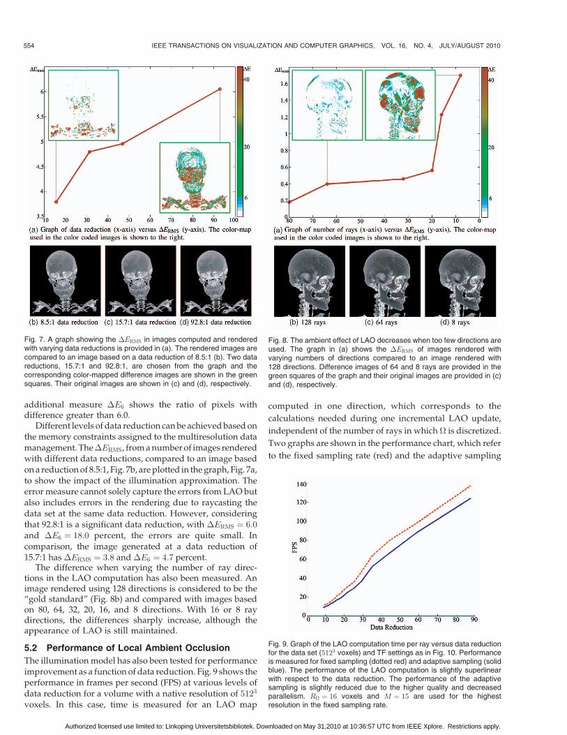
Different levels of data reduction can be achieved based onthe memory constraints assigned to the multiresolution datamanagement. The �ERMS, from a number of images renderedwith different data reductions, compared to an image basedon a reduction of 8.5:1, Fig. 7b, are plotted in the graph, Fig. 7a,to show the impact of the illumination approximation. Theerror measure cannot solely capture the errors from LAO butalso includes errors in the rendering due to raycasting thedata set at the same data reduction. However, consideringthat 92.8:1 is a significant data reduction, with �ERMS ¼ 6:0and �E6 ¼ 18:0 percent, the errors are quite small. Incomparison, the image generated at a data reduction of15.7:1 has �ERMS ¼ 3:8 and �E6 ¼ 4:7 percent.
The difference when varying the number of ray direc-tions in the LAO computation has also been measured. Animage rendered using 128 directions is considered to be the“gold standard” (Fig. 8b) and compared with images basedon 80, 64, 32, 20, 16, and 8 directions. With 16 or 8 raydirections, the differences sharply increase, although theappearance of LAO is still maintained.
5.2 Performance of Local Ambient Occlusion
The illumination model has also been tested for performanceimprovement as a function of data reduction. Fig. 9 shows theperformance in frames per second (FPS) at various levels ofdata reduction for a volume with a native resolution of 5123
voxels. In this case, time is measured for an LAO map
computed in one direction, which corresponds to the
calculations needed during one incremental LAO update,
independent of the number of rays in which � is discretized.
Two graphs are shown in the performance chart, which refer
to the fixed sampling rate (red) and the adaptive sampling
554 IEEE TRANSACTIONS ON VISUALIZATION AND COMPUTER GRAPHICS, VOL. 16, NO. 4, JULY/AUGUST 2010
Fig. 7. A graph showing the �ERMS in images computed and renderedwith varying data reductions is provided in (a). The rendered images arecompared to an image based on a data reduction of 8.5:1 (b). Two datareductions, 15.7:1 and 92.8:1, are chosen from the graph and thecorresponding color-mapped difference images are shown in the greensquares. Their original images are shown in (c) and (d), respectively.
Fig. 8. The ambient effect of LAO decreases when too few directions areused. The graph in (a) shows the �ERMS of images rendered withvarying numbers of directions compared to an image rendered with128 directions. Difference images of 64 and 8 rays are provided in thegreen squares of the graph and their original images are provided in (c)and (d), respectively.
Fig. 9. Graph of the LAO computation time per ray versus data reductionfor the data set (5123 voxels) and TF settings as in Fig. 10. Performanceis measured for fixed sampling (dotted red) and adaptive sampling (solidblue). The performance of the LAO computation is slightly superlinearwith respect to the data reduction. The performance of the adaptivesampling is slightly reduced due to the higher quality and decreasedparallelism. R� ¼ 16 voxels and M ¼ 15 are used for the highestresolution in the fixed sampling rate.
Authorized licensed use limited to: Linkoping Universitetsbibliotek. Downloaded on May 31,2010 at 10:36:57 UTC from IEEE Xplore. Restrictions apply.

rate (blue). The performance increase of the LAO map
creation is slightly superlinear in the level of data reduction
since the reduction increases the number of low-resolution
blocks present in the volume with two contributing effects:
the first being that the number of voxels is decreased and so
less occlusion calculations are required and the second that
low-resolution blocks permit a longer sample step and so the
average time per occlusion calculation is reduced. The
performance change due to using adaptive and fixed step
length is limited, but it depends on the mixture of LOD blocks.
One negative effect of adaptive sampling is an increased
execution time due to the need to process different numbers
of samples for neighboring voxels. However, the resulting
illumination has fewer artifacts when LAO computations are
performed using adaptive sampling.
5.3 Benefits and Limitations
This section discusses the benefits and limitations of the
LAO method in the context of the following problem areas:
1. understanding of shapes and densities;2. local relative position of complex structures;
3. artifacts in noisy data sets;4. illumination at cross sections; and5. tissue separation using emission.
The two images in Fig. 12 show how the LAO emphasizes
the complex shape of the blood vessels and their position
relative to the skull surface. LAO also enhances the visibility
of the skull structure itself. A limitation, and at the same time
a flexibility, of the method is the user-specified size of the
LAO region, which determines at what scale shadowing
effects will be included. With an increase of the LAO sphere,
more neighboring structures are included and the contrast in
shadows is enhanced, as can be seen in Fig. 13.R� is, here, the
radius of the surrounding LAO sphere. Another benefit of
the method is the possibility to emphasize density of material
using light propagation, such as the skull in (Fig. 10).LAO is less sensitive to noisy data sets compared with
gradient-based methods, such as diffuse illumination. Gaus-sian white noise is added to the synthetic data set, with a meanof 0 and variances of 0.0001, 0.001, and 0.01. Close-up viewsare shown in Fig. 11 and the full views are shown in Fig. 14.The shape of the “T” is almost lost in the diffuse illuminated
HERNELL ET AL.: LOCAL AMBIENT OCCLUSION IN DIRECT VOLUME RENDERING 555
Fig. 10. The density of the skull is more apparent with LAO (b) compared
to diffuse shading (a). However, high-frequency surface details are lost,
and in some situations, it can be beneficial to combine the methods in
order to explore fine structures, see Fig. 16.
Fig. 11. Close-ups of the T in images (a-d), and (h-k) of Fig. 14. Theshading and perception of the shapes in the diffusely illuminated T(upper row) are much more sensitive to noise than the LAO-illuminatedT (lower row). The rectangular shape of the T stem is still perceived in allimages for LAO, but almost lost at even the lowest noise level for diffuseillumination.
Fig. 12. Example images showing the enhanced 3D structure made clear through the LAO method. R� ¼ 32 voxels.
Authorized licensed use limited to: Linkoping Universitetsbibliotek. Downloaded on May 31,2010 at 10:36:57 UTC from IEEE Xplore. Restrictions apply.

images while it is preserved in the LAO-illuminated images.The images in Figs. 14b, 14c, and 14d are rendered withdiffuse shading and compared to Fig. 14a, while images inFigs. 14i, 14j, and 14k are illuminated with LAO andcompared to Fig. 14h. Errors are computed with the methoddescribed above and the error images are found in Figs. 14e,14f, 14g and Fig. 14l, 14m, 14n, respectively. In the LAO-rendered images, it is primarily the edges that are affectedwhen noise of low variance is added.
When the volume has a high signal-to-noise-ratio (SNR), itcan also be valuable to combine LAO with diffuse shading toexplore fine structures, as can be seen in Fig. 16c. Intensifyingstructures with gradient-dependent shading in volumes with
low SNR, however, becomes more disturbing than helpful. Itis important to note that the LAO method implicitly filters thelight information with a kernel that has the extent of the LAOsphere. In cases when a trained eye is looking for details in thedata, diffuse shading (despite noise) may be more relevantthan the improved overall shading quality. As an example ofshading of noisy data, an MRI data set is shown in Fig. 15.Interaction with clip planes is an important feature in medicalDVR and LAO has the potential to improve the quality of therendering of the cross section. The boundaries of the activevolume often have poorly defined gradients and gradient-based illumination is, therefore, inappropriate. Using LAO inthe illumination of the MRI data set, as shown in Fig. 15,
556 IEEE TRANSACTIONS ON VISUALIZATION AND COMPUTER GRAPHICS, VOL. 16, NO. 4, JULY/AUGUST 2010
Fig. 13. A large radius of the surrounding sphere � includes more structures in the vicinity of each voxel in LAO computations. The shadows,
therefore, become darker and more defined. Measurements of computing one ray in LAO are shown within parenthesis.
Fig. 14. Comparing diffuse shading and LAO with increasing noise in the data. (a) and (h) are renderings of a synthetic data set illuminated with diffuse
shading and LAO, respectively. Gaussian noise has been added to the data set with a mean of zero and different variance �. (b)-(d) are illuminated with
diffuse shading and (i)-(k) are illuminated with LAO. Errors are provided in (e)-(g) and (l)-(n) for the noisy data sets relative to the image of their respective
non-noisy data set using the same shading technique. Errors in LAO primarily appear on edges in data sets with low variance.
Authorized licensed use limited to: Linkoping Universitetsbibliotek. Downloaded on May 31,2010 at 10:36:57 UTC from IEEE Xplore. Restrictions apply.

significantly enhances the visibility of shapes. Radiologistshave verified the potential value of the LAO method for clipplane rendering.
The effects of the emissive material within a medicalvolume can be seen in Fig. 16, where the rendering of avirtual autopsy case is shown. In these images, the bulletand the many fragments, which are crucial to the forensicpathologist, are not as evident with diffuse shading as theyare with LAO and emissive tissues. The middle imageclearly shows these foreign bodies as well as revealing thebone structure more clearly. The emissive material approachcompares well with the dual TF technique introduced in [1]to highlight similar foreign bodies. Combining LAO anddiffuse shading (right) can, in some applications, intensifythe perception of shapes, which indicates that diffuseshading has benefits over LAO in cases when there is awell-defined transition with a sharp gradient in the data.
It can be difficult to perceive a global context inapplications, where semitransparent tissues are used tocomplement other important structures in the volume.Using a separate absorption TF in the LAO computationsopens possibilities for intensifying shadowing for semitran-
sparent tissues by increasing the absorption. An example isshown in Fig. 17, where the right image uses a separateabsorption setting for the soft tissue of a lion. The shape ofthe skin appears much clearer in the right image whencompared with the left. Improved context is only noticeablewhen the absorption of the tissue used in the rendering passis lower than the LAO absorption.
6 CONCLUSIONS AND FUTURE WORK
In this paper, we have presented an efficient method forinclusion of local ambient and emissive lighting for volumerendering applications. Restricting the ambient occlusion toa local neighborhood, combined with a multiresolutionframework and adaptive sampling, enables rendering atinteractive speeds, a delay only being introduced by therecalculation of the occlusion volume when transferfunctions are changed, and then providing a progressiverefinement that allows uninterrupted user interaction.
The results show that the LAO method has properties thatcan improve DVR when used on its own or when combined
HERNELL ET AL.: LOCAL AMBIENT OCCLUSION IN DIRECT VOLUME RENDERING 557
Fig. 15. A magnetic resonance (MR) volume with different illumination methods. The undefined gradients at the clipped boundary results in
misleading illumination when using diffuse shading (a). Shapes are more easily perceived in the LAO-illuminated volume (c). (b) illustrates the
illumination without consideration of clip planes whereas (c) is computed with additional light at the clipped boundary.
Fig. 16. Example images showing the enhanced information from the emissive materials. The bullet and fragments are clearly visible in the
abdomen. The effect of the LAO in revealing the bone structure is also very clear. A combination of LAO and diffuse shading intensifies fine details,
for example, the structure of the pelvis.
Authorized licensed use limited to: Linkoping Universitetsbibliotek. Downloaded on May 31,2010 at 10:36:57 UTC from IEEE Xplore. Restrictions apply.

with other shading models. In particular, the salience of localfeatures in the volume can be improved, especially when thedepth order of structures is crucial. Furthermore, the methodis less sensitive to noisy data than gradient-based shadingapproaches, which can be exploited to improve the visualimpression of data from, for instance, MRI scans.
The developed methods have been tested by radiologistswho considered LAO to be promising for diagnosis andsurgical planning. Further evaluation through a comprehen-sive user study is, however, needed to establish the improveddiagnostic value of LAO in medicine, and for which generalcases, it improves the quality of volume-rendered images. Weforesee many possible further developments. Directionalambient occlusion could yield very distinct shadows, whileallowing the user to interactively alter the lighting couldfurther improve the depth perception. This would requirefaster calculation of the illumination parameters afterchanges in the light direction. Another area of interest is therelation of emission with tissue classification methods tofurther improve detection of regions of interest such as bloodvessels or tumors.
ACKNOWLEDGMENTS
This work has been funded by the Swedish ResearchCouncil grant 621-2004-3829 and the Strategic ResearchCenter MOVIII, founded by the Swedish Foundation forStrategic Research, SSF. The medical data sets used areprovided by Siemens and the Center for Medical ImageScience and Visualization (CMIV). The authors would liketo thank the coworkers at the Division for Visual Informa-tion Technology and Applications.
REFERENCES
[1] P. Ljung, C. Winskog, A. Persson, C. Lundstrom, and A.Ynnerman, “Full Body Virtual Autopsies Using a State-of-the-Art Volume Rendering Pipeline,” IEEE Trans. Visualization andComputer Graphics, vol. 12, no. 5, pp. 869-876, Sept./Oct. 2006.
[2] L. Serra, R.A. Kockro1, C.G. Guan, N. Hern, E.C.K. Lee, Y.H. Lee,C. Chan, and W.L. Nowinski, “Multimodal Volume-Based TumorNeurosurgery Planning in the Virtual Workbench,” Proc. Int’lConf. Medical Image Computing and Computer-Assisted Intervention(MICCAI ’98), vol. 1496, pp. 1007-1015, 1998.
[3] P. Jannin, O.J. Fleig, E. Seigneuret, X. Mor, M. Raimbault, and R.C.France, “Multimodal and Multi Informational Neuro-Naviga-
tion,” Proc. Conf. Computer Assisted Radiology and Surgery (CARS),pp. 167-172, 2000.
[4] A. Neubauer, L. Mroz, S. Wolfsberger, R. Wegenkittl, M.-T.Forster, and K. Buhler, “Steps—An Application for Simulation ofTranssphenoidal Endonasal Pituitary Surgery,” Proc. IEEE Conf.Visualization 2004, pp. 513-520, Oct. 2004.
[5] J. Beyer, M. Hadwiger, S. Wolfsberger, and K. Buhler, “High-Quality Multimodal Volume Rendering for Preoperative Planningof Neurosurgical Interventions,” IEEE Trans. Visualization andComputer Graphics, vol. 13, no. 6, pp. 1696-1703, Nov./Dec. 2007.
[6] M.S. Langer and H.H. Bulthoff, “Perception of Shape fromShading on a Cloudy Day,” Technical Report 73, Max-PlanckInstitut fur biologische Kybernetik, Oct. 1999.
[7] B.T. Phong, “Illumination for Computer-Generated Images,” PhDdissertation, The Univ. of Utah, 1973.
[8] J.F. Blinn, “Models of Light Reflection for Computer SynthesizedPictures,” ACM SIGGRAPH Computer Graphics, vol. 11, no. 2,pp. 192-198, 1977.
[9] H.W. Jensen, Realistic Image Synthesis Using Photon Mapping, A.K.Peters, Ltd., 2001.
[10] E. Cerezo, F. Perez-Cazorla, X. Pueyo, F. Seron, and F. Sillion, “ASurvey on Participating Media Rendering Techniques,” The VisualComputer, http://artis.inrialpes.fr/Publications/2005/CPPSS05,2005.
[11] U. Behrens and R. Ratering, “Adding Shadows to a Texture-BasedVolume Renderer,” Proc. IEEE Symp. Volume Visualization, pp. 39-46, 1998.
[12] M. Hadwiger, A. Kratz, C. Sigg, and K. Buhler, “GPU-AcceleratedDeep Shadow Maps for Direct Volume Rendering,” Proc. ACMEurographics/SIGGRAPH, pp. 49-52, 2006.
[13] J. Kniss, S. Premoze, C. Hansen, and D. Ebert, “InteractiveTranslucent Volume Rendering and Procedural Modeling,” Proc.IEEE Conf. Visualization, pp. 109-116, 2002.
[14] P. Desgranges, K. Engel, and G. Paladini, “Gradient-Free Shading:A New Method for Realistic Interactive Volume Rendering,” Proc.Conf. Vision, Modelling, and Visualization, Nov. 2005.
[15] F. Hernell, P. Ljung, and A. Ynnerman, “Efficient Ambient andEmissive Tissue Illumination Using Local Occlusion in Multi-resolution Volume Rendering,” Proc. Eurographics/IEEE-VGTCSymp. Volume Graphics, 2007.
[16] S. Zhukov, A. Inoes, and G. Kronin, “An Ambient LightIllumination Model,” Rendering Techniques, G. Drettakis andN. Max, eds., pp. 45-56, Springer-Verlag Wien, 1998.
[17] A. Iones, A. Krupkin, M. Sbert, and S. Zhukov, “Fast, RealisticLighting for Video Games,” IEEE Computer Graphics and Applica-tions, vol. 23, no. 3, pp. 54-64, May 2003.
[18] M. Tarini, P. Cignoni, and C. Montani, “Ambient Occlusion andEdge Cueing to Enhance Real Time Molecular Visualization,”IEEE Trans. Visualization and Computer Graphics, vol. 12, no. 5,pp. 1237-1244, Sept./Oct. 2006.
[19] A.J. Stewart, “Vicinity Shading for Enhanced Perception ofVolumetric Data,” Proc. IEEE Conf. Visualization, pp. 355-362, 2003.
558 IEEE TRANSACTIONS ON VISUALIZATION AND COMPUTER GRAPHICS, VOL. 16, NO. 4, JULY/AUGUST 2010
Fig. 17. A CT scan of a lion (512 � 512 � 1,100 voxels) rendered using the same TF for LAO and rendering (left and top TF). Using a specific TF,
with increased opacity for LAO (right and bottom TF), creates a more dynamic shading effect. The dotted lines refer to the absorption TF in the LAO
computations while the height of the opaque trapezoids refers to the absorption in the rendering.
Authorized licensed use limited to: Linkoping Universitetsbibliotek. Downloaded on May 31,2010 at 10:36:57 UTC from IEEE Xplore. Restrictions apply.

[20] P. Shanmugam and O. Arikan, “Hardware Accelerated AmbientOcclusion Techniques on GPUs,” Proc. Conf. Interactive 3DGraphics and Games, pp. 73-80, 2007.
[21] M. Sattler, R. Sarlette, G. Zachmann, and R. Klein, “Hardware-Accelerated Ambient Occlusion Computation,” Proc. Conf.Vision, Modeling, and Visualization, pp. 119-135, http://www.gabrielzachmann.org/, Nov. 2004.
[22] J.T. Kajiya, “The Rendering Equation,” Proc. ACM SIGGRAPH,vol. 20, no. 4, pp. 143-150, 1986.
[23] C. Wyman, S. Parker, P. Shirley, and C. Hansen, “InteractiveDisplay of Isosurfaces with Global Illumination,” IEEE Trans.Visualization and Computer Graphics, vol. 12, no. 2, pp. 186-196,Mar./Apr. 2006.
[24] C. Rezk-Salama, “GPU-Based Monte-Carlo Volume Raycasting,”Proc. Conf. Pacific Graphics, 2007.
[25] D. Weiskopf, K. Engel, and T. Ertl, “Interactive ClippingTechniques for Texture-Based Volume Visualization and VolumeShading,” IEEE Trans. Visualization and Computer Graphics, vol. 9,no. 3, pp. 298-312, July-Sept. 2003.
[26] M.A. Magnor, K. Hildebrand, A. Lintu, and A.J. Hanson,“Reflection Nebula Visualization,” Proc. IEEE Conf. Visualization,pp. 255-262, 2005.
[27] R. Kahler, J. Wise, T. Abel, and H.-C. Hege, “GPU-AssistedRaycasting for Cosmological Adaptive Mesh Refinement Simula-tions,” Proc. Conf. Volume Graphics, pp. 103-110, 2006.
[28] N.A. Svakhine and D.S. Ebert, “Interactive Volume Illustrationand Feature Halos,” Proc. 11th Pacific Conf. Computer Graphics andApplications (PG ’03), p. 347, 2003.
[29] S. Bruckner and E. Groller, “Enhancing Depth-Perception withFlexible Volumetric Halos,” IEEE Trans. Visualization and ComputerGraphics, vol. 13, no. 6, pp. 1344-1351, Nov./Dec. 2007.
[30] S. Bruckner, S. Grimm, A. Kanitsar, and M.E. Groller, “IllustrativeContext-Preserving Volume Rendering,” Proc. EuroVis Conf.,pp. 69-76, May 2005.
[31] N. Max, “Optical Models for Direct Volume Rendering,” IEEETrans. Visualization and Computer Graphics, vol. 1, no. 2, pp. 99-108,June 1995.
[32] P. Ljung, C. Lundstrom, A. Ynnerman, and K. Museth, “TransferFunction Based Adaptive Decompression for Volume Renderingof Large Medical Data Sets,” Proc. IEEE Conf. Volume Visualizationand Graphics, pp. 25-32, 2004.
[33] P. Ljung, C. Lundstrom, and A. Ynnerman, “MultiresolutionInterblock Interpolation in Direct Volume Rendering,” Proc. IEEEEurographics/Visualization Conf., pp. 259-266, 2006.
[34] P. Ljung, “Adaptive Sampling in Single Pass, GPU-BasedRaycasting of Multiresolution Volumes,” Proc. Eurographics/IEEEInt’l Workshop Volume Graphics, pp. 39-46, 2006.
[35] M. Kraus and T. Ertl, “Adaptive Texture Maps,” Proc. Euro-graphics/ACM SIGGRAPH, pp. 7-15, 2002.
[36] M.D. Fairchild, Color Appearance Models, Addison Wesley Long-man, Inc., 1998.
Frida Hernell received the MS degree in mediatechnology in 2004 from Linkoping University,Sweden. Since 2005, she has been workingtoward the PhD degree in scientific visualizationat the Visual Information Technology and Appli-cations (VITA) and CMIV. From 2004 to 2005,she worked as a research engineer at the Centerfor Medical Image Science and Visualization(CMIV) at the University Hospital in Linkoping.Her research interest includes volume render-
ing, illumination, and interactive visualization.
Patric Ljung received the MS degree ininformation technology and the PhD degree inscientific visualization from Linkoping University,Sweden, in 2000 and 2006, respectively. Be-tween 2000 and 2007, he was a faculty staffmember at the Norrkoping Visualization andInteraction Studio (NVIS) and the Visual Infor-mation Technology and Applications (VITA)Group, also collaborating with CMIV at Linkop-ing University. Since 2007, he has been a
research scientist in the Imaging and Visualization Department atSiemens Corporate Research in Princeton, New Jersey. From 1989 to1995, he worked as a software engineer with embedded and telecomsystems. His research interest includes interactive visualization of largedata sets, volume rendering, graphics system design, and softwaredesign and engineering. He is a member of the IEEE Computer Society,Eurographics, and the ACM/SIGGRAPH.
Anders Ynnerman received the BSc and PhDdegrees in physics respectively from the Uni-versity of Lund in 1986 and Gothenburg Uni-versity in 1992. He has directed the nationalsupercomputing organizations NSC and SNIC.Since 1999, he has been a professor of scientificvisualization at Linkoping University, and in2000, he founded the Norrkoping Visualizationand Interaction Studio (NVIS). His currentprimary research interest lies in the area of
visualization of large data sets and multimodal interaction techniques.He is a member of the IEEE, the IEEE Computer Society, Eurographics,and the ACM.
. For more information on this or any other computing topic,please visit our Digital Library at www.computer.org/publications/dlib.
HERNELL ET AL.: LOCAL AMBIENT OCCLUSION IN DIRECT VOLUME RENDERING 559
Authorized licensed use limited to: Linkoping Universitetsbibliotek. Downloaded on May 31,2010 at 10:36:57 UTC from IEEE Xplore. Restrictions apply.