Load-sensing control block - Airline Hydraulics · Load-sensing control block 1/52 ... The highest...
52
1/52 Load-sensing control block in sandwich plate design Type M4-15 Nominal size 15 Component series 2X Nominal pressure 350 bar (pump side) Nominal pressure 420 bar (actuator side) Maximum flow – Pump side: 300 l/min for central inlet element 200 l/min for lateral inlet element – Actuator side: 200 l/min with load-holding function 200 l/min with pressure compensator 160 l/min with pressure compensator and load-holding function RE 64283/10.08 Replaces: 06.05 Table of contents Content Page Features 2 Function 2 Cross-section, Symbol 3 Technical data 4, 5 Modular design 6, 7 Ordering code 8 to 11 Order example 12 to 14 Inlet elements 15 to 18 Directional valve elements 19 Pressure compensator 19 LS pressure limitation 20 to 24 Main spool 25, 26 Flow 27 Types of operation, cover A 28 to 33 Voltage supply and plug-in connectors 33 Types of operation cover B 34 Secondary valves 35 End elements 36 to 39 Unit dimensions 40 to 49 On-board electronics: Electronic pilot module 50 Electronic pilot module: Pin assignment 51 Electronic pilot module: Accessories 51, 52
-
Upload
vuongthien -
Category
Documents
-
view
223 -
download
4
Transcript of Load-sensing control block - Airline Hydraulics · Load-sensing control block 1/52 ... The highest...

1/52Load-sensing control block in sandwich plate design
Type M4-15
Nominal size 15Component series 2XNominal pressure 350 bar (pump side)Nominal pressure 420 bar (actuator side)Maximum flow– Pump side: 300 l/min for central inlet element 200 l/min for lateral inlet element– Actuator side: 200 l/min with load-holding function 200 l/min with pressure compensator 160 l/min with pressure compensator and load-holding function
RE 64283/10.08Replaces: 06.05
Table of contents
Content PageFeatures 2Function 2Cross-section, Symbol 3Technical data 4, 5Modular design 6, 7Ordering code 8 to 11Order example 12 to 14Inlet elements 15 to 18Directional valve elements 19Pressure compensator 19LS pressure limitation 20 to 24Main spool 25, 26Flow 27
Types of operation, cover A 28 to 33Voltage supply and plug-in connectors 33Types of operation cover B 34Secondary valves 35End elements 36 to 39Unit dimensions 40 to 49On-board electronics: Electronic pilot module 50Electronic pilot module: Pin assignment 51Electronic pilot module: Accessories 51, 52
Table of contents 1Features 2Function 2Cross-section 3Symbol 3Technical data 4Modular design: Control block with lateral inlet element 6Ordering code 8Order example closed center with lateral inlet element 12Order example closed center with central inlet element 13Order example closed center with combined inlet element 14Inlet elements 15Central inlet elements 17Directional valve elements: Pressure compensator 19Directional valve elements: LS pressure limitation 20Directional valve elements: Main spool 25Directional valve elements: Flow 27Directional valve elements: Types of operation, cover A – mechanical 28Directional valve elements: Types of operation, cover A – hydraulic 28Directional valve elements: Types of operation, cover A – servohydraulic 28Directional valve elements: Types of operation Cover A – electrohydraulically switchable 29Directional valve elements: Types of operation Cover A – electrohydraulically switchable 30Directional valve elements: Types of operation Cover A – electrohydraulically proportional 31Directional valve elements: Types of operation Cover A – electrohydraulically proportional 32Directional valve elements: Types of operation cover A – on-board electronics 32Directional valve elements: Voltage supply and plug-in connectors 33Directional valve elements: Types of operation cover B 34Directional valve elements: Secondary valves 35End elements 36Diversion plates for central inlet element 39Unit dimensions: Line connections 40Unit dimensions: Lateral inlet elements 41Unit dimensions: Central inlet elements 42Unit dimensions: Directional valve element 43Unit dimensions: Operation 44Unit dimensions: End elements for lateral inlet element 45Unit dimensions: Control block closed center with lateral inlet element 47Unit dimensions: Control block closed center with central inlet element 48Unit dimensions: Control block closed center with combined inlet element 49On-board electronics: Electronic pilot module (EMP2) 50Electronic pilot module: Parameter specifications 50Electronic pilot module: Pin assignment 51Electronic pilot module: Accessories 51

2/52 Bosch Rexroth AG Hydraulics M4-15 RE 64283/10.08
FeaturesSystem
Load pressure-independent flow control –Open center for fixed displacement pump•Closed center for variable displacement pump•
TypeSandwich plate design –
Inlet element•up to 9 directional valve elements•up to 18 directional valve elements with central inlet ele-•ment, thereof max. 6 with servo operationEnd element•
Types of operation –Mechanical (hand lever following)•Hydraulic•Servohydraulic•Electrohydraulic (switching, proportional)•Electrohydraulic with on-board electronics (EPM2)•
FlowLoad pressure-compensated –High repeatability –Low hysteresis –Adjustable via stroke limiter –
Pressure relief functionInlet element –
Pilot operated pressure valves with large nominal width•Directional valve element / actuator ports –
Compact pressure valves with feed function•LS pressure limitation –
Adjustable as per actuator port•External pressure setting as per actuator port possible•Electro-proportional as per section•
Fields of applicationCranes – – Drilling equipmentLarge-scale and telescopic fork lifts – – Truck applicationsRock crushers – Municipal vehicles –Forestry machines – Stationary applications –
Function
Load pressure compensationPressure changes at the actuators or at the pump are com-pensated by the pressure compensator (3). The flow to the actuator remains constant even if the load varies.Flow limitationThe maximum flow can be set mechanically and individually via stroke limiter (6).Pressure relief functionThe LS pressure as per actuator port can be adjusted inter-nally via the LS pressure relief valves (4) or externally via the LS ports MA, MB.Pressure relief/anti-cavitation valves (5) protect the actuator ports A and B against pressure peaks and against external forces.The highest load pressure is signaled to the pump via the LS line and the integrated shuttle valves (7).
Control block M4-15The directional valves are proportional valves according to the load-sensing principle.Actuator controlThe flow direction and level of flow reaching the actuator ports (A or B) is determined at the main spool (2).Pressure reducing valves (9) control the position of the main spool (2). The level of electrical current at the pressure reduc-ing valve determines the level of pilot pressure in the spring chambers (8) and therefore also the stroke of the main spool (P → A; P → B).The pressure difference at the main spool (2), and therefore the flow to the actuator, is maintained constant via the pres-sure compensator (3).

� ������
�������
���
���
��
���
���
���
���
���
�� ��
� �
�
� �
���
����
�
�
� ���
�
��
�
� �
� ����
���
����
�
�
�� ���� ���
�
3/52 Bosch Rexroth AG Hydraulics M4-15 RE 64283/10.08
Cross-section1 Housing 6.1 A side stroke limiter 9.2 Pressure reducing valve
(pilot control valve “b”)2 Main spool 6.2 B side stroke limiter3 Pressure compensator 7 LS shuttle valve 10 Compression spring4 LS pressure relief valves 8 Spring chamber 11 Hand lever5.1 Secondary valve 9.1 Pressure reducing valve
(pilot control valve “a”)12 A side cover
5.2 Plug screw 13 B side cover
Symbol
ConnectionsP PumpA, B ActuatorT TankX Pilot oil supplyY Pilot oil drainLS Load-sensing (LS)MA, MB External LS ports

4/52 Bosch Rexroth AG Hydraulics M4-15 RE 64283/10.08
generalInstallation position AnyType of connection Pipe thread according to ISO 228/1Weight Inlet element Closed center J kg 6.6
Open center P kg 10.0 with priority valve VZ kg 10.7Central inlet element closed center JZ kg 8.5Directional valve element Operation
Hydraulic Electrohydraulic with EPM2kg 7.1 7.5 7.8
Excess weight of handle-operated lever kg 0.6End element kg 5.8
Hydraulic fluid and ambient temperature range ϑ °C –20 to +80Painting Standard priming
hydraulicMax. volume flow at port
P qV, max l/min 300 with central inlet elementl/min 200 with lateral inlet element
A, B qV, max l/min 160 with pressure compensator and load-holding function (model “S”)l/min 200 with pressure compensator, without load-holding function
(model “T”)l/min 200 without pressure compensator (model “C”)
Nominal pressure pnom bar 350Max. operating pressure at port
P p bar 350A, B p bar 420LS p bar 330T p bar 30Y p bar At zero pressure to the tank
Max. pilot pressure at port
X p bar 35a, b p bar 35
Pilot pressure range Hydraulic p bar 8.5 to 22.5Electrohydraulic p bar 6.5 to 17.2
Required control Δp at the control block 1)
Models S; C p bar 18Model T p bar 25
Recommended hydraulic pilot control devices TH6…, characteristic curve 97, see RE 64552LS pressure limitation (adjustment ranges) bar 50 to 149; 150 to 330 (selected in the factory)Hydraulic fluid Mineral oil (HL, HLP) according to DIN 51524, other hy-
draulic fluids, such as HEES (synthetic esters) according to VDMA 24568, as well as hydraulic fluids as specified under RE 90221, at request
Viscosity range Hydraulic ν mm²/s 10 to 380Servohydraulic ν mm²/s 16 to 200 2)
Max. admissible degree of contamination of the hydraulic fluid cleanliness class according to ISO 4406 (c)
Class 20/18/15, for this we recommend a filter with a mini-mumretentionrateofβ≥75
Technical data (Please inquire in case the intended use of unit is outside the given values!)
1) Please observe the design instructions on pilot oil supply at servohydraulic operation on page 18.
1) Between 200 and 380mm²/s reduced maximum quantity.

Hydraulics Bosch Rexroth AGRE 64283/10.08 M4-15 5/52
1) Plug-in connectors are not included in the scope of supply and need to be ordered separately, see page 33.
Note!The technical data were determined at a viscosity of ν = 32 mm²/s (HLP46: 50°C).You can find more information on using the hydraulic prod-ucts of Bosch Rexroth in our publication “Hydraulic valves for mobile applications - General information”, RE 64020-B1
servohydraulicSTDS 0014STDS 0015STDS 0016
See data sheet RE 29617See data sheet RE 29616See data sheet RE 29618
electricalElectrical pilot control valves FTWE 2 K...; see RE 58007 1)
FTDRE 2 K...; see RE 58032 1)
Recommended amplifiers (further control options at request)
RA 1-0/10; 1 axis, see RE 95230RA 2-1/10; 4 to 6 axes, see RE 95230Control devices RC see RE 95200
On-board electronics (EPM2) Data from page 50; see also RE 64518-B
Technical data (Please inquire in case the intended use of unit is outside the given values!)

6/52 Bosch Rexroth AG Hydraulics M4-15 RE 64283/10.08
Modular design: Control block with lateral inlet elementControl blocks of the series M4-15 have a modular structure. They can be combined ideally for the corresponding application.1. Inlet element A: Closed center “VR” with external priority actuators B: Open center “P” C: Closed center “J”2. Directional valve elements2.1 LS pressure limitation2.2 Secondary valves2.3 Operation cover “A” A: Hydraulic operation “H” B: Electrohydraulic operation “W” C: Servohydraulic operation “S” D: Electrohydraulic operation with on-board electronics (EPM2) “CBA”
2.4 Operation cover “B” A: Standard cover “–” B: Mechanical operation “K” with hand lever2.5 Electro-proportional LS pressure limitation3. End element A: with LS unloading “LA” and “LZ” B: with LS port and pilot oil supply “LAY” and “LZY” C: with LS port and pilot oil supply “LAX” and “LZX”
2.4
2.
3.
2.3
1.2.5
A
B
A
B
D
A
B
C
2.2
2.2
2.1
A
B
C
C

Hydraulics Bosch Rexroth AGRE 64283/10.08 M4-15 7/52
2.
1.
2.4
2.
3.
2.1
2.3 3.
2.5
A
B
A
B
C
D
E
C
A
B
2.2
A
B
D
C
Modular design: Control block with central inlet element1. Central inlet element A: Closed center central “JZ” B: Closed center central “VZ” with priority valve2. Directional valve elements2.1 LS pressure limitation2.2 Secondary valves2.3 Operation cover “A” A: Hydraulic operation “H” B: Electrohydraulic operation “W” C: Servohydraulic operation “S” D: Electrohydraulic operation with on-board electronics (EPM2) “CBA’2.4 Operation cover “B” A: Standard cover “–” B: Mechanical operation “K” with hand lever2.5 Electro-proportional LS pressure limitation
3. End element A: Diversion plate with external priority port “LVZ” B: Diversion plate “LU” C: with LS unloading “LA” and “LZ” D: with LS port and pilot oil supply “LAY” and “LZY” E: with LS port and pilot oil supply “LAX” and “LZX”

8/52 Bosch Rexroth AG Hydraulics M4-15 RE 64283/10.08
M4 15 2X
Ordering code
Number of directional valves 1 to 18 1)
Nominal size 15 = 15Component series 20 to 29 = 2X (unchanged installation and connection dimensions)
Closed center
Open center
Lateral = J = PLateral, internal priority actuator external subordinate actuator
= VL
Lateral, external priority actua-tor, internal subordinate actuator
= VR
Central = JZCentral with priority valve = VZCentral for M4-12/15 = JK 2)
Without primary pressure relief valve = Q(not with model P)Without primary pressure relief valve = …(pressure info in bar, 3-digit)Priority valve (only with V.)Static priority valve = ADynamic priority valve = BLS pressure limitation at priority valve (V.) = …(pressure info in bar, 3-digit)
= Preferred program (M4 configurator)1) Max. 9 elements per side, thereof a maximum of 6
with servohydraulic operation2) Consult Technical Sales.
Short code Inlet elements Directional valve elements
1. Spool axis
2. Spool axis
3. Spool axis etc.
Order details see pages 10 and 11
Example for a short code of the M4-15 control block with three directional valve elements:
M4 – 4567 – 2 0 / 3 M4 – 15 J W2 K V 01 –450
Control block No.Component series of unit series (2 X)Revision status of the seriesNumber of directional valve elementsInletOperation A side (prevalent operation)Operation B side (prevalent operation)Sealing materialThreaded connectionSO number if any
Short codeComplete control blocks are defined in accor-dance with the type key. The order text is to determine the technical fea-tures and requirements. From the order text the Rexroth distribution organi-zation derives a short code and a material number.
Hydraulics Bosch Rexroth AGRE 64283/10.08 M4-15 9/52
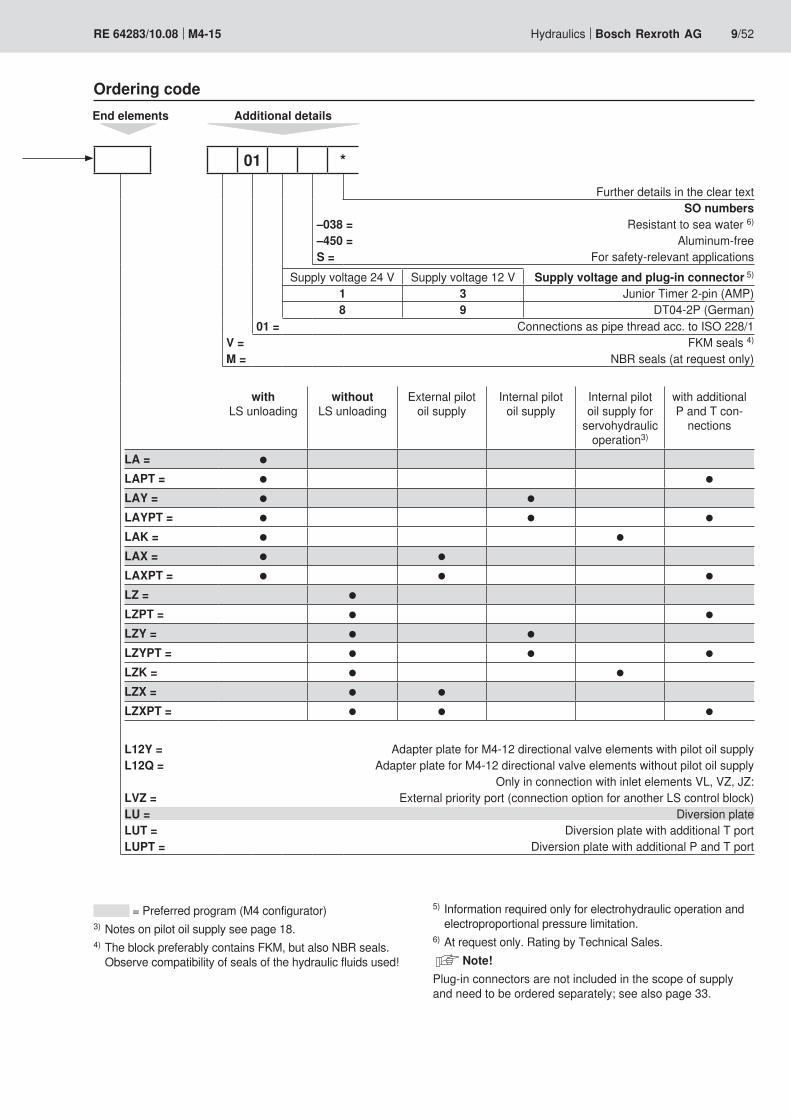
Ordering codeEnd elements Additional details
Further details in the clear textSO numbers
–038 = Resistant to sea water 6)
–450 = Aluminum-freeS = For safety-relevant applications
Supply voltage 24 V Supply voltage 12 V Supply voltage and plug-in connector 5)
1 3 Junior Timer 2-pin (AMP)8 9 DT04-2P (German)
01 = Connections as pipe thread acc. to ISO 228/1V = FKM seals 4)
M = NBR seals (at request only)
with LS unloading
without LS unloading
External pilot oil supply
Internal pilot oil supply
Internal pilot oil supply for
servohydraulic operation3)
with additional P and T con-
nections
LA = ●LAPT = ● ●LAY = ● ●LAYPT = ● ● ●LAK = ● ●LAX = ● ●LAXPT = ● ● ●LZ = ●LZPT = ● ●LZY = ● ●LZYPT = ● ● ●LZK = ● ●LZX = ● ●LZXPT = ● ● ●
L12Y = Adapter plate for M4-12 directional valve elements with pilot oil supplyL12Q = Adapter plate for M4-12 directional valve elements without pilot oil supply
Only in connection with inlet elements VL, VZ, JZ:LVZ = External priority port (connection option for another LS control block)LU = Diversion plateLUT = Diversion plate with additional T portLUPT = Diversion plate with additional P and T port
01 *
= Preferred program (M4 configurator)3) Notes on pilot oil supply see page 18.4) The block preferably contains FKM, but also NBR seals.
Observe compatibility of seals of the hydraulic fluids used!
5) Information required only for electrohydraulic operation and electroproportional pressure limitation.
6) At request only. Rating by Technical Sales. Note!Plug-in connectors are not included in the scope of supply and need to be ordered separately; see also page 33.
10/52 Bosch Rexroth AG Hydraulics M4-15 RE 64283/10.08
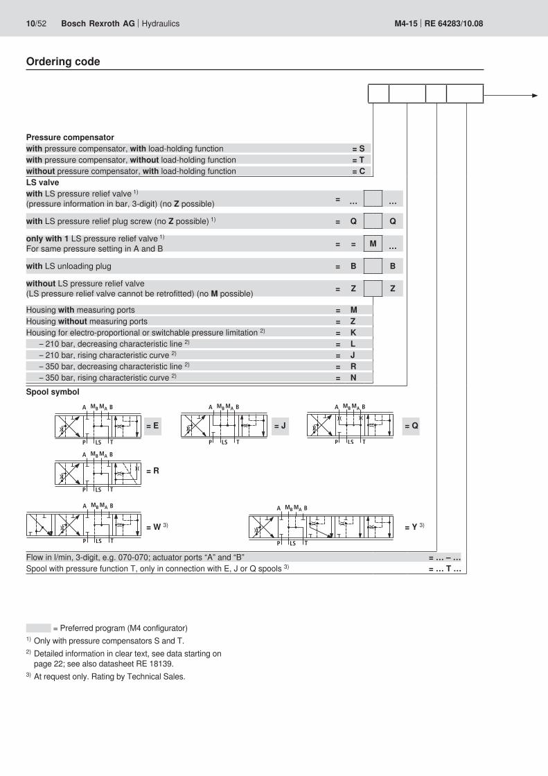
Ordering code
Pressure compensatorwith pressure compensator, with load-holding function = Swith pressure compensator, without load-holding function = Twithout pressure compensator, with load-holding function = CLS valvewith LS pressure relief valve 1)
(pressure information in bar, 3-digit) (no Z possible) = … …
with LS pressure relief plug screw (no Z possible) 1) = Q Q
only with 1 LS pressure relief valve 1) For same pressure setting in A and B = = M …
with LS unloading plug = B B
without LS pressure relief valve (LS pressure relief valve cannot be retrofitted) (no M possible) = Z Z
Housing with measuring ports = MHousing without measuring ports = ZHousing for electro-proportional or switchable pressure limitation 2) = K – 210 bar, decreasing characteristic line 2) = L – 210 bar, rising characteristic curve 2) = J – 350 bar, decreasing characteristic line 2) = R – 350 bar, rising characteristic curve 2) = NSpool symbol
= E = J = Q
= R
= W 3) = Y 3)
Flow in l/min, 3-digit, e.g. 070-070; actuator ports “A” and “B” = … – …Spool with pressure function T, only in connection with E, J or Q spools 3) = … T …
= Preferred program (M4 configurator)1) Only with pressure compensators S and T.2) Detailed information in clear text, see data starting on
page 22; see also datasheet RE 18139.3) At request only. Rating by Technical Sales.
���� ��
� ���

Hydraulics Bosch Rexroth AGRE 64283/10.08 M4-15 11/52
Ordering code
*
Further details in the clear textSO numbers
–011 = One-sided operation, two spool positionsSecondary valves
H … = Pressure relief/anti-cavitation valve, adjustableE = Feed valve, adjustableQ = Plug screw (secondary valves can be retrofitted)
Operation B side cover– = Standard cover
Hand lever position without hand lever60° 0° -60°
K L M R Hand lever followingN O P X Hand lever, non-following 7)
See notes on page 34 Further versions
Supply voltage 24 V Supply voltage 12 V Supply voltage and plug-in connector 6)
1 3 Junior Timer 2-pin (AMP)8 9 DT04-2P (German)
Operation A side coverM = MechanicalH = HydraulicS = Servohydraulic 3) 5)
Standard
with damping orifice, on both
sideswith measuring
ports, both sides
with damping orifice, with measuring ports,
both sides
Orifice + check valve for hydrau-
lic overrideW2 W8 G2 Electrohydraulically proportionalW4 W5 W6 W7 G4 Electrohydraulically switchable
Standard with position sensor with measuring ports, both sides
Orifice + check valve, both sides Electrohydraulic with digital on-
board electronics (EPM2) (EPM2) 4)CBA CPA 3) CXA CXC
Actu
ator
por
t “A”
Actu
ator
por
t “B”
= Preferred program (M4 configurator)3) At request only. Rating by Technical Sales.4) Further order details according to RE 64815-B.
The delivery comprises daisy chain cabling.5) Not in combination with following hand lever.
6) Information required only for electrohydraulic operation and electroproportional pressure limitation.
7) Only lockable in central position. Note!Plug-in connectors are not included in the scope of supply and need to be ordered separately; see also page 33.
���������� ������
� �� ��
�� ������
�
�
���
�� ���
�
��
��
�
�
�
�
�
�
�
�
�
�
�
�
��
�� ��
12/52 Bosch Rexroth AG Hydraulics M4-15 RE 64283/10.08
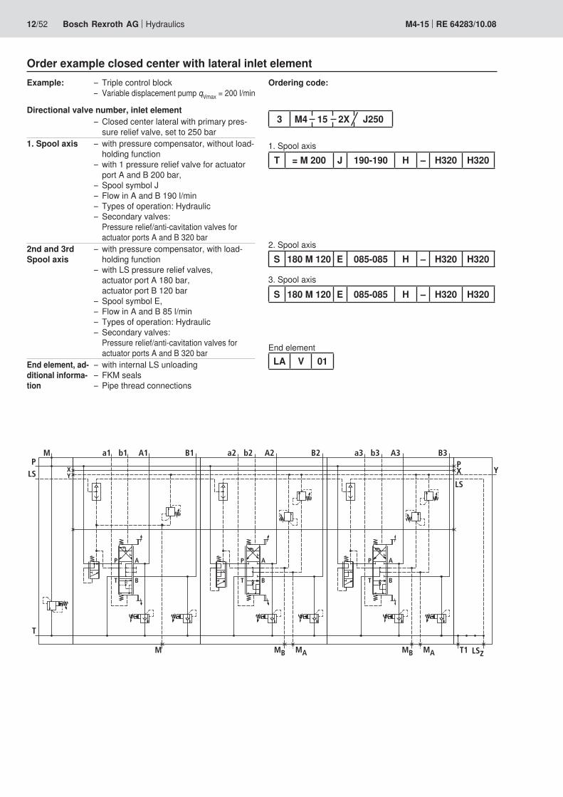
Order example closed center with lateral inlet elementExample: Triple control block –
Variable displacement pump – qVmax = 200 l/min
Directional valve number, inlet elementClosed center lateral with primary pres- –sure relief valve, set to 250 bar
1. Spool axis with pressure compensator, without load- –holding functionwith 1 pressure relief valve for actuator –port A and B 200 bar,Spool symbol J –Flow in A and B 190 l/min –Types of operation: Hydraulic –Secondary valves: –Pressure relief/anti-cavitation valves for actuator ports A and B 320 bar
2nd and 3rd Spool axis
with pressure compensator, with load- –holding functionwith LS pressure relief valves, –actuator port A 180 bar, actuator port B 120 barSpool symbol E, –Flow in A and B 85 l/min –Types of operation: Hydraulic –Secondary valves: –Pressure relief/anti-cavitation valves for actuator ports A and B 320 bar
End element, ad-ditional informa-tion
with internal LS unloading –FKM seals –Pipe thread connections –
Ordering code:
1. Spool axis
2. Spool axis
3. Spool axis
T = M 200 J 190-190 H – H320 H320
LA V 01
3 M4 15 2X J250
S 180 M 120 E 085-085 H – H320 H320
End element
S 180 M 120 E 085-085 H – H320 H320

���
���
��
��
��
��
� �
��
���
�� ��
�� � �
���������
�
���
�
�
�
�
�
�
�
�
�
����� ��
Hydraulics Bosch Rexroth AGRE 64283/10.08 M4-15 13/52
Order example closed center with central inlet elementExample: Double control block –
Variable displacement – pump qVmax = 200 l/min
Directional valve number, end elementDiversion plate –
1. Spool axis without pressure compensator, with load- –holding functionwithout LS pressure relief valves –(cannot be retrofitted)Spool symbol E –Flow in A and B 175 l/min –Types of operation: –Electrohydraulically proportional, 24 VOverriding hand lever (following) –Secondary valve bores closed –
Inlet element Central inlet element with priority valve –(dynamic), set to 250 barPrimary pressure relief valve, set to 300 bar –
2. Spool axis with pressure compensator, with load-hold- –ing functionwith LS pressure relief valves, –actuator port A 180 bar, actuator port B 120 barwith electro proportional pressure limitation, –210 bar (decreasing characteristic line)Spool symbol E –Flow in A and B 90 l/min –Types of operation: digital OBE –Overriding hand lever (following) –Secondary valve bores closed –
End element with internal LS unloading and pilot oil supply –FKM seals –Pipe thread connections –
Ordering code:
1. Spool axis
2. Spool axis
C Z Z Z E 175-175 W2 1 K Q Q
LAY V 01
S 270 L 300 E 090-090 CBA K Q Q
End element
2 M4 15 2X LU
VZ 300 B 250Inlet element
�
�� � � ���
�
�
�
�
�� ��
���
���
�� ��
�
�
�
�
�
���
��
��
��
���
���
�
�
�
�
���
���
����� ����� �������� ����� ����� �����
�� �� �� ���� ��
14/52 Bosch Rexroth AG Hydraulics M4-15 RE 64283/10.08
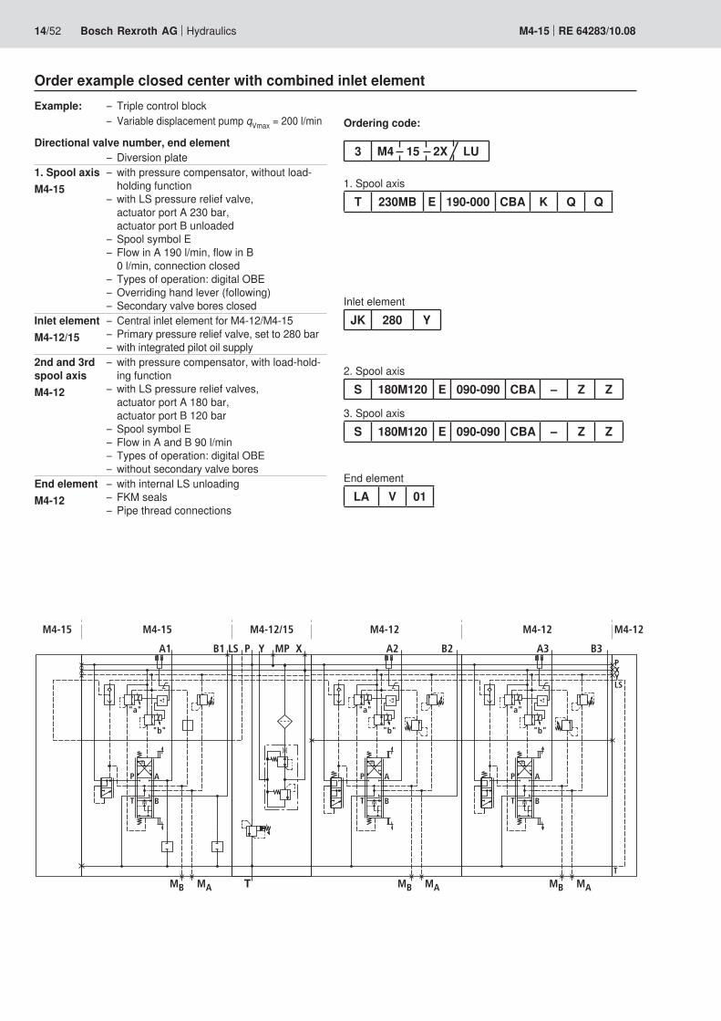
Order example closed center with combined inlet elementExample: Triple control block –
Variable displacement – pump qVmax = 200 l/min
Directional valve number, end elementDiversion plate –
1. Spool axisM4-15
with pressure compensator, without load- –holding functionwith LS pressure relief valve, – actuator port A 230 bar, actuator port B unloadedSpool symbol E –Flow in A 190 l/min, flow in B –0 l/min, connection closedTypes of operation: digital OBE –Overriding hand lever (following) –Secondary valve bores closed –
Inlet elementM4-12/15
Central inlet element for M4-12/M4-15 –Primary pressure relief valve, set to 280 bar –with integrated pilot oil supply –
2nd and 3rd spool axisM4-12
with pressure compensator, with load-hold- –ing functionwith LS pressure relief valves, – actuator port A 180 bar, actuator port B 120 barSpool symbol E –Flow in A and B 90 l/min –Types of operation: digital OBE –without – secondary valve bores
End elementM4-12
with internal LS unloading –FKM seals –Pipe thread connections –
Ordering code:
1. Spool axis
2. Spool axis
T 230MB E 190-000 CBA K Q Q
LA V 01
S 180M120 E 090-090 CBA – Z Z
End element
3 M4 15 2X LU
JK 280 Y
3. Spool axisS 180M120 E 090-090 CBA – Z Z
Inlet element

� �� ���
�
��
��
��
��
�� ��� ����
�� ��� ��� ��� ���
��
��
���
���
���
� ���
�
� ���
�
� ���
�
Hydraulics Bosch Rexroth AGRE 64283/10.08 M4-15 15/52
Inlet elementsCharacteristic curves (measured at ν = 41 mm²/s and ϑ = 50°C)
Open centerCirculation pressure P → T
Priority valve
Pressure differential in bar →Fl
ow q
Vs in
l/m
in
(prio
rity
actu
ator
)Flow in l/min →
Circ
ulat
ion
pres
sure
ppin
bar
→
Closed center without primary pressure relief valveOrdering code:
M4 15 2X J Q
Short descriptionFor variable displacement pumps up to 200 l/min –
Closed center with primary pressure relief valveOrdering code:
M4 15 2X J …
Short descriptionFor variable displacement pumps up to 200 l/min –Pressure information – in bar after J… reqired (3-digit)Technical data on primary valve according to –RE 64642, characteristic curve D5
Open center with primary pressure relief valveOrdering code:
M4 15 2X P …
Short descriptionFor fixed displacement pumps up to 200 l/min –Pressure information – in bar after P… reqired (3-digit)Technical data on primary valve according to –RE 64642, characteristic curve D5
16/52 Bosch Rexroth AG Hydraulics M4-15 RE 64283/10.08
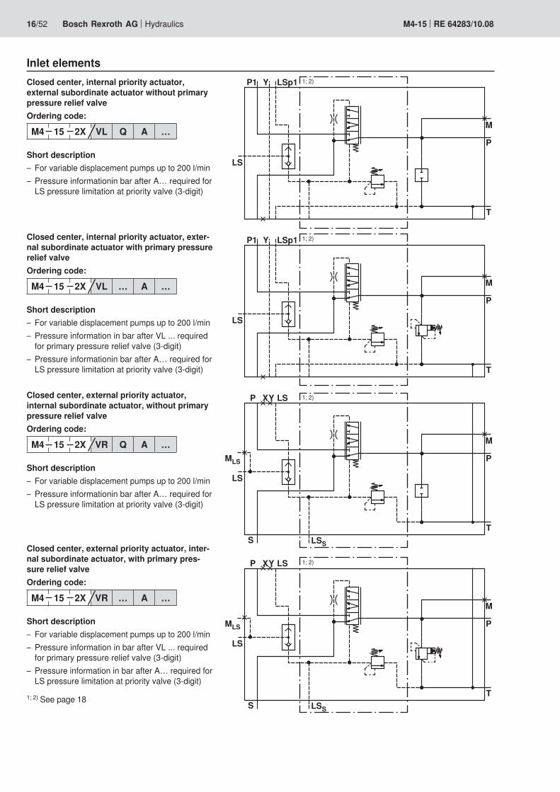
Inlet elementsClosed center, internal priority actuator, external subordinate actuator without primary pressure relief valveOrdering code:
M4 15 2X VL Q A …
Short descriptionFor variable displacement pumps up to 200 l/min –Pressure information – in bar after A… required for LS pressure limitation at priority valve (3-digit)
Closed center, internal priority actuator, exter-nal subordinate actuator with primary pressure relief valveOrdering code:
M4 15 2X VL … A …
Short descriptionFor variable displacement pumps up to 200 l/min –Pressure information – in bar after VL ... required for primary pressure relief valve (3-digit)Pressure information – in bar after A… required for LS pressure limitation at priority valve (3-digit)
Closed center, external priority actuator, internal subordinate actuator, without primary pressure relief valveOrdering code:
M4 15 2X VR Q A …
Short descriptionFor variable displacement pumps up to 200 l/min –Pressure information – in bar after A… required for LS pressure limitation at priority valve (3-digit)
Closed center, external priority actuator, inter-nal subordinate actuator, with primary pres-sure relief valveOrdering code:
M4 15 2X VR … A …
Short descriptionFor variable displacement pumps up to 200 l/min –Pressure information – in bar after VL ... required for primary pressure relief valve (3-digit)Pressure information – in bar after A… required for LS pressure limitation at priority valve (3-digit)
1; 2) See page 18
�
�
�
��
������� 1; 2)
�
�
�
��
������� 1; 2)
�
�
�
��
����
���
�
� ���
1; 2)
�
�
�
��
����
���
�
� ���
1; 2)

�
�
��
� � � ���
���
�
�
��
� � � ���
���
�
�
��
���� �
� ���
1; 2)
�
�
��
���� �
� ���
1; 2)
Hydraulics Bosch Rexroth AGRE 64283/10.08 M4-15 17/52
Central inlet elementsClosed center, without primary pressure relief valveOrdering code:
M4 15 2X JZ Q
Short descriptionFor variable displacement pumps up to 300 l/min –
Closed center, with primary pressure relief valveOrdering code:
M4 15 2X JZ …
Short descriptionFor variable displacement pumps up to 300 l/min –Pressure information – in bar after JZ ... required for primary pressure relief valve (3-digit)Technical data on primary valve according to –RE 64642, characteristic curve D5
Closed center, with priority valve without primary pressure relief valveOrdering code:
M4 15 2X VZ Q A …
Short descriptionFor variable displacement pumps up to 200 l/min –Pressure information – in bar after A… required for LS pressure limitation at priority valve (3-digit)
Closed center, with priority valve with primary pressure relief valveOrdering code:
M4 15 2X VZ … A …
Short descriptionFor variable displacement pumps up to 200 l/min –Pressure information – in bar after VR ... required for primary pressure relief valve (3-digit)Pressure information – in bar after A… required for LS pressure limitation at priority valve (3-digit)
1; 2) See page 18

�
�
��
���� �
� ���
1; 2)
�
�
��
���� �
� ���
1; 2)
Hydraulics Bosch Rexroth AGRE 64283/10.08 M4-15 18/52
Inlet elements1) For priority actuators with constant flow model “V … A” is
recommended.2) For dynamic priority consumer loads (e.g. steering) model
“V … B” is recommended.
Notes on the dimensioning of control oil supply with servohydraulic operation
If servohydraulic operation is used in the control block, please note:External pilot oil supply:
p – st = 30 + 2 bar constantq – st = 2 l/min per servohydraulic spool axisRequired and mandatory for inlet element P –
Internal pilot oil supply:6 servohydraulically controlled spool axes maximum possible –No pilot oil supply for external actuators –Δ–– p at the inlet element needs to be 35 bar at leastNo internal pilot oil supply in the inlet element –
� �� ��� ��� ��� ��� ���
��
��
��
��
���
���
���
���
�
�
�
� �
���
� �
�����
�
�
�
� �
���
� �
�����
Hydraulics Bosch Rexroth AGRE 64283/10.08 M4-15 19/52
Directional valve elements: Pressure compensator
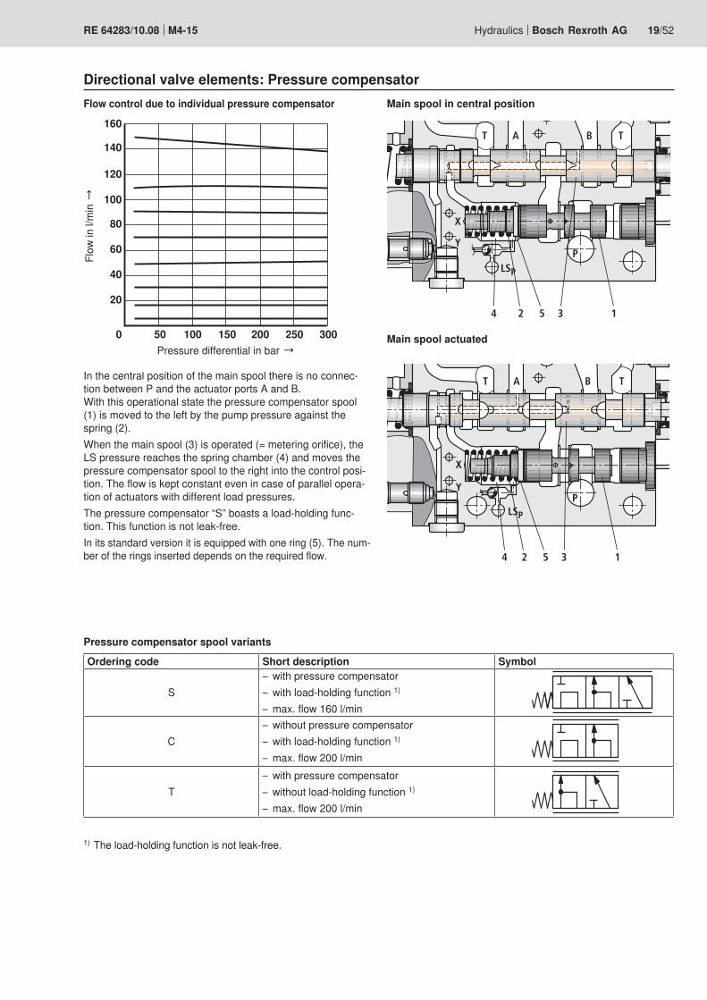
In the central position of the main spool there is no connec-tion between P and the actuator ports A and B. With this operational state the pressure compensator spool (1) is moved to the left by the pump pressure against the spring (2).When the main spool (3) is operated (= metering orifice), the LS pressure reaches the spring chamber (4) and moves the pressure compensator spool to the right into the control posi-tion. The flow is kept constant even in case of parallel opera-tion of actuators with different load pressures.The pressure compensator “S” boasts a load-holding func-tion. This function is not leak-free.In its standard version it is equipped with one ring (5). The num-ber of the rings inserted depends on the required flow.
Flow control due to individual pressure compensator
Pressure differential in bar →
Flow
in l/
min
→Main spool in central position
Main spool actuated
Pressure compensator spool variants
Ordering code Short description Symbol
Swith pressure compensator –with load-holding function – 1)
max. flow 160 l/min –
Cwithout pressure compensator –with load-holding function – 1)
max. flow 200 l/min –
Twith pressure compensator –without load-holding function – 1)
max. flow 200 l/min –
1) The load-holding function is not leak-free.

� �� ��� ��� ��� ��� ��� ���
��
��
��
��
���
� ���
�
��
�
��
� �
� ����
���
��
� ���
�
��
�
��
� �
� ����
���
��
20/52 Bosch Rexroth AG Hydraulics M4-15 RE 64283/10.08
Directional valve elements: LS pressure limitationCharacteristic curvesReduction of the actuator flow due to LS pressure limitationMinimum settings: 50 barMaximum settings: 330 bar
Settings (example)LS-pressure in bar →
Flow
in %
→
With LS pressure relief valve and LS plug screwOrdering code:
S … M Q J …–… W2 1 – Q H…
Short descriptionPressure information in bar for actuator port A – (3-digit)Plug screw for actuator port B –For the model “QMQ”, the LS pressure limitation –can be retrofitted at the directional valve element.The LS pressure can be influenced externally –via the ports MA and MB These ports can also be used as measuring ports.
With LS pressure relief valve and unloading plugOrdering code:
S … M B J …–000 W2 1 – H… H…
Short descriptionPressure information in bar for actuator port A – (3-digit)Unloading plug for actuator port B –E.g. for cylinders with one-sided operation –
Note!Please consult Technical Sales.

� ���
�
��
�
� �
� ����
���
� ���
�
��
�
�
� �
� ����
���
Hydraulics Bosch Rexroth AGRE 64283/10.08 M4-15 21/52
Without LS pressure relief valvesOrdering code:
S Z Z Z J …–… W2 1 – H… H…
Short descriptionLS pressure relief valve cannot be retrofitted –Housing without measuring connections –
Only with 1 LS pressure relief valve and LS plug screwOrdering code:
S = M … J …–… W2 1 – H… H…
Short descriptionOnly 1 LS-DB for same pressure setting in A and –B, pressure information in bar (3-digit)1 measuring port –
Directional valve elements: LS pressure limitation

� ���
�
��
�
�
�� �
� �
�
��
��� ���
22/52 Bosch Rexroth AG Hydraulics M4-15 RE 64283/10.08
Directional valve elements: LS pressure limitation
Short descriptionDifferentiation between:1. Type KBPS – electrohydraulically proportional2. Type MH2DAD and type KBPS2. Type KKDE – electrohydraulically switchable3. Porting pattern KBPS and cover plate4. Housing KBPS and plug
The exact description of the valve has to be stated as follows in clear text.
KBPS…BA: Decreasing characteristic curve
KBPS…AA: Rising characteristic curve
1. Electro-proportional pressure relief valve type KBPS (see also datasheets RE 18139-04; RE 18139-05)Preferred program:
S … L … J …–… H – H… H… KBPSL8BA
S … J … J …–… H – H… H… KBPSL8AA
S … R … J …–… H – H… H… KBPSR8BA
S … N … J …–… H – H… H… KBPSR8AA
Extension program, e. g.:
S … K … J …–… H – H… H… KBPSH8BA -033
Electro-proportional / hydraulically switchable pressure limitation
2. Pressure cut-off valve type MH2DAD and electro-proportional pressure relief valve, type KBPS (see also datasheets RE 18139-04; RE 18139-05)
S … K … J …–… H – H… H… MH2DAD+KBPSH8BA
� ����� �� ��
��
���
���
���
���
���
���
���
���
�
�
�
�
Hydraulics Bosch Rexroth AGRE 64283/10.08 M4-15 23/52
Directional valve elements: LS pressure limitation
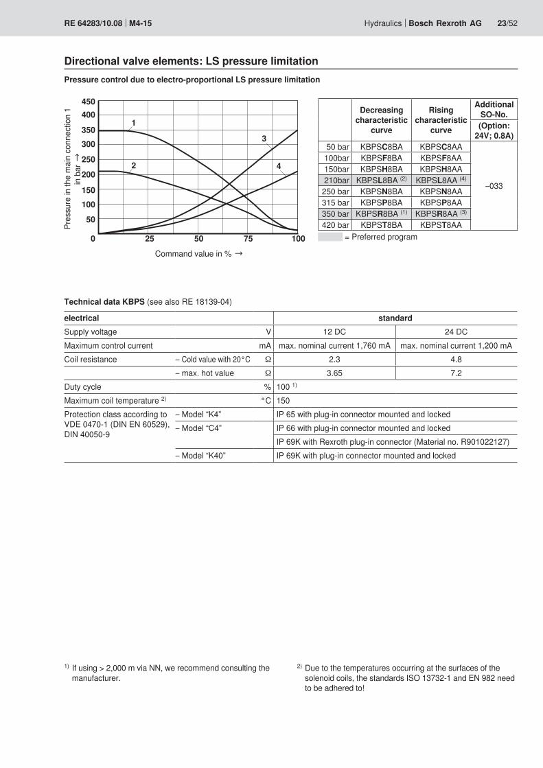
Technical data KBPS (see also RE 18139-04)
electrical standardSupply voltage V 12 DC 24 DCMaximum control current mA max. nominal current 1,760 mA max. nominal current 1,200 mACoil resistance – Cold value with 20°C Ω 2.3 4.8
– max. hot value Ω 3.65 7.2Duty cycle % 100 1)
Maximum coil temperature 2) °C 150Protection class according to VDE 0470-1 (DIN EN 60529), DIN 40050-9
– Model “K4” IP 65 with plug-in connector mounted and locked– Model “C4” IP 66 with plug-in connector mounted and locked
IP 69K with Rexroth plug-in connector (Material no. R901022127)– Model “K40” IP 69K with plug-in connector mounted and locked
1) If using > 2,000 m via NN, we recommend consulting the manufacturer.
Pressure control due to electro-proportional LS pressure limitationPr
essu
re in
the
mai
n co
nnec
tion
1
in b
ar →
Command value in % →
Decreasing characteristic
curve
Rising characteristic
curve
Additional SO-No.(Option:
24V; 0.8A)50 bar KBPSC8BA KBPSC8AA
–033
100bar KBPSF8BA KBPSF8AA150bar KBPSH8BA KBPSH8AA210bar KBPSL8BA (2) KBPSL8AA (4)
250 bar KBPSN8BA KBPSN8AA315 bar KBPSP8BA KBPSP8AA350 bar KBPSR8BA (1) KBPSR8AA (3)
420 bar KBPST8BA KBPST8AA = Preferred program
2) Due to the temperatures occurring at the surfaces of the solenoid coils, the standards ISO 13732-1 and EN 982 need to be adhered to!

� �
�
24/52 Bosch Rexroth AG Hydraulics M4-15 RE 64283/10.08
Directional valve elements: LS pressure limitation3. 2/2-directional spool valve type KKDE
S … K … J …–… H – H… H… KKDER8PA
De-energized open De-energized closedKKDER8PA KKDER8NA
KKDE…NA: De-energized closed
KKDE…PA: De-energized open
Technical data KKDE (see also RE 18136-08)
electrical standardType of voltage Direct voltageSupply voltage V 12 DC 24 DCVoltage tolerance and ambient temperature See characteristic curve RE 18136-08 page 5Power consumption Ω 22Duty cycle % See characteristic curve RE 18136-08 page 5Maximum coil temperature 2) °C 150Switching time according to ISO 6403 (solenoid horizontal)
– ON ms ≤–80– OFF ms ≤–150
Maximum number of cycles cy/h 15,000Protection class according to VDE 0470-1 (DIN EN 60529), DIN 40050-9
– Model “K4” IP 65 with plug-in connector mounted and locked– Model “C4” IP 66 with plug-in connector mounted and locked
IP 69K with Rexroth plug-in connector (Material no. R901022127)– Model “K40” IP 69K with plug-in connector mounted and locked
At the electrical connection “K4”, the protective earth-ing conductor (PE ) has to be connected properly.
1) If using > 2,000 m via NN, we recommend consulting the manufacturer.
2) Due to the temperatures occurring at the surfaces of the solenoid coils, the European standards EN 563 and EN 982 need to be adhered to!
Note!Consumer load pressure does not become zero pressure!
Plug
Cover plate
4. Porting pattern KBPS and cover plate
S … K … J …–… H – H… H… A
5. Housing KBPS and plug
S … K … J …–… H – H… H… Q
Hydraulics Bosch Rexroth AGRE 64283/10.08 M4-15 25/52
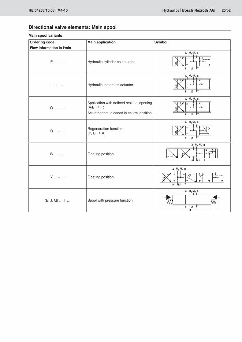
Directional valve elements: Main spoolMain spool variants
Ordering codeFlow information in l/min
Main application Symbol
E … – … Hydraulic cylinder as actuator
J … – … Hydraulic motors as actuator
Q … – …Application with defined residual opening (A/B → T)Actuator port unloaded in neutral position
R … – … Regeneration function (P, B → A)
W … – … Floating position
Y … – … Floating position
���� ��
� ���
(E, J, Q) … T … Spool with pressure function

�����
����� �� �� �� �� ��
����� �� �� �� �� ��
��� ���� ������ ���� ��� ���� ��� ����
��
��
��
��
���
���
�
����� ��� ��� ��� ���
���
���� ��� ������� ���� ���� ���� ���� ����
�
�
���
26/52 Bosch Rexroth AG Hydraulics M4-15 RE 64283/10.08
Directional valve elements: Main spool
Electrohydraulic operation
Hydraulic operation
Servohydraulic opera-tion (at ν = 32 mm²/s)
Typi
cal f
low
in l/
min
→
Spool characteristic curves (symmetric spools)
P → A/B
Pilot pressure in bar →No
min
al fl
ow →
Current in amperes at 24V →
Current in milliamperes →
Current in amperes at 12V →
Command value in digits (steps) →
Digital on-Board-elec-tronics (EPM2)
Hydraulics Bosch Rexroth AGRE 64283/10.08 M4-15 27/52
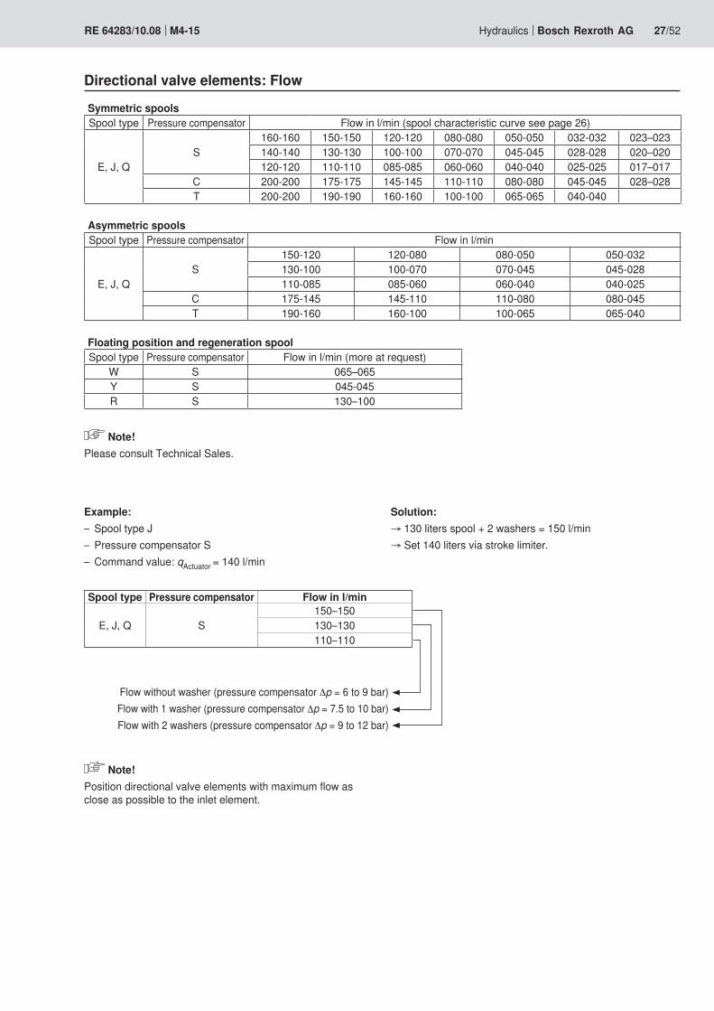
Flow without washer (pressure compensator Δp = 6 to 9 bar)Flow with 1 washer (pressure compensator Δp = 7.5 to 10 bar)Flow with 2 washers (pressure compensator Δp = 9 to 12 bar)
Directional valve elements: Flow
Symmetric spoolsSpool type Pressure compensator Flow in l/min (spool characteristic curve see page 26)
E, J, QS
160-160 150-150 120-120 080-080 050-050 032-032 023–023140-140 130-130 100-100 070-070 045-045 028-028 020–020120-120 110-110 085-085 060-060 040-040 025-025 017–017
C 200-200 175-175 145-145 110-110 080-080 045-045 028–028T 200-200 190-190 160-160 100-100 065-065 040-040
Asymmetric spoolsSpool type Pressure compensator Flow in l/min
E, J, QS
150-120 120-080 080-050 050-032130-100 100-070 070-045 045-028110-085 085-060 060-040 040-025
C 175-145 145-110 110-080 080-045T 190-160 160-100 100-065 065-040
Floating position and regeneration spoolSpool type Pressure compensator Flow in l/min (more at request)
W S 065–065Y S 045-045R S 130–100
Note!Please consult Technical Sales.
Example:Spool type J –Pressure compensator S –Command value: – qActuator = 140 l/min
Spool type Pressure compensator Flow in l/min
E, J, Q S150–150130–130110–110
Solution:→ 130 liters spool + 2 washers = 150 l/min→ Set 140 liters via stroke limiter.
Note!Position directional valve elements with maximum flow as close as possible to the inlet element.

� �
� �
����
�
��
�
��
��
����
� �
� �
����
�
��
�
�
�
����
� ���
�
��
�
� �
� �
28/52 Bosch Rexroth AG Hydraulics M4-15 RE 64283/10.08
Directional valve elements: Types of operation, cover A – mechanicalMechanical (encapsulated)Ordering code:
S … M … J …–… M K H… H…
Short descriptionMechanical operation of the main spool. In case –of non-operation centering in central position by springsAll handle-operated lever position options are –available (K, L, M etc.) comp. also type key on page 11
1) Following hand lever2) Non-following hand lever
HydraulicOrdering code:
S … M … J …–… H – H… H…
Short descriptionRecommended hydraulic pilot control devices: –Type TH6 according to RE 64555
Directional valve elements: Types of operation, cover A – hydraulic
ServohydraulicOrdering code:
S Z Z Z J …–… S – Q Q
Short descriptionVoltage: 7VDC min –Type of current: Direct current –Nominal current: – ±20 mAMax. current: – ±25 mASTDS 0014; see RE 29617-B2 –STDS 0015; see RE 29616-B2 –STDS 0016; see RE 29618-B2 –
Note!Rating by Technical Sales.
Directional valve elements: Types of operation, cover A – servohydraulic

�� ��
�
��
�
� �
� ����
���
����
��
��
� �
� �
����
�
��
�
���
���
����
����
�
��
�
� �
� ����
���
����
Hydraulics Bosch Rexroth AGRE 64283/10.08 M4-15 29/52
Electrohydraulically switchableOrdering code:
S … M … J …–… W4 1 – H… H…
Short descriptionOn/off valves, type FTWE 2 K according to –RE 58007
Directional valve elements: Types of operation Cover A – electrohydraulically switchable
Electrohydraulically switchable with measuring ports on both sidesOrdering code:
S … M … J …–… W6 3 – H… H…
Short descriptionOn/off valves, type FTWE 2 K according to –RE 58007
Electrohydraulically switchable with damping orifice on both sidesOrdering code:
S … M … J …–… W5 3 – H… H…
Short descriptionOn/off valves, type FTWE 2 K according to –RE 58007

����
�
��
�
�
�� �
� ����
���
����
����
�
��
�
� �
� ����
���
����
��
��
30/52 Bosch Rexroth AG Hydraulics M4-15 RE 64283/10.08
Directional valve elements: Types of operation Cover A – electrohydraulically switchable
Electrohydraulically switchable with orifice and check valve for hydraulic overrideOrdering code:
S … M … J …–… G4 3 – H… H…
Short descriptionOn/off valves, type FTWE 2 K according to –RE 58007
Electrohydraulically switchable with damping orifice, with measuring ports on both sidesOrdering code:
S … M … J …–… W7 1 – H… H…
Short descriptionOn/off valves, type FTWE 2 K according to –RE 58007
Technical data FTWE 2K (see also RE 58007)
electrical Type of voltage Direct voltageNominal voltage V 12 24Powerconsumptionat20℃ W 14.4 14.4Coil resistance R20 Ω 10 40Duty cycle % 100Switching time ton ms ≤–20
toff ms ≤–30Protection class according to DIN 40050-9
– Solenoid IP 69K– Electric connection C4
K40IP 69K 1)
IP 69K 1)
Switching frequency Hz 5
1) Recommended plug-in connector see page 33.
� �
� ����
���
����
�� ��
�
��
�
��
��
����
�
��
�
� �
� ����
���
����
��
��
�� ��
�
��
�
�
�� �
� ����
���
����
Hydraulics Bosch Rexroth AGRE 64283/10.08 M4-15 31/52
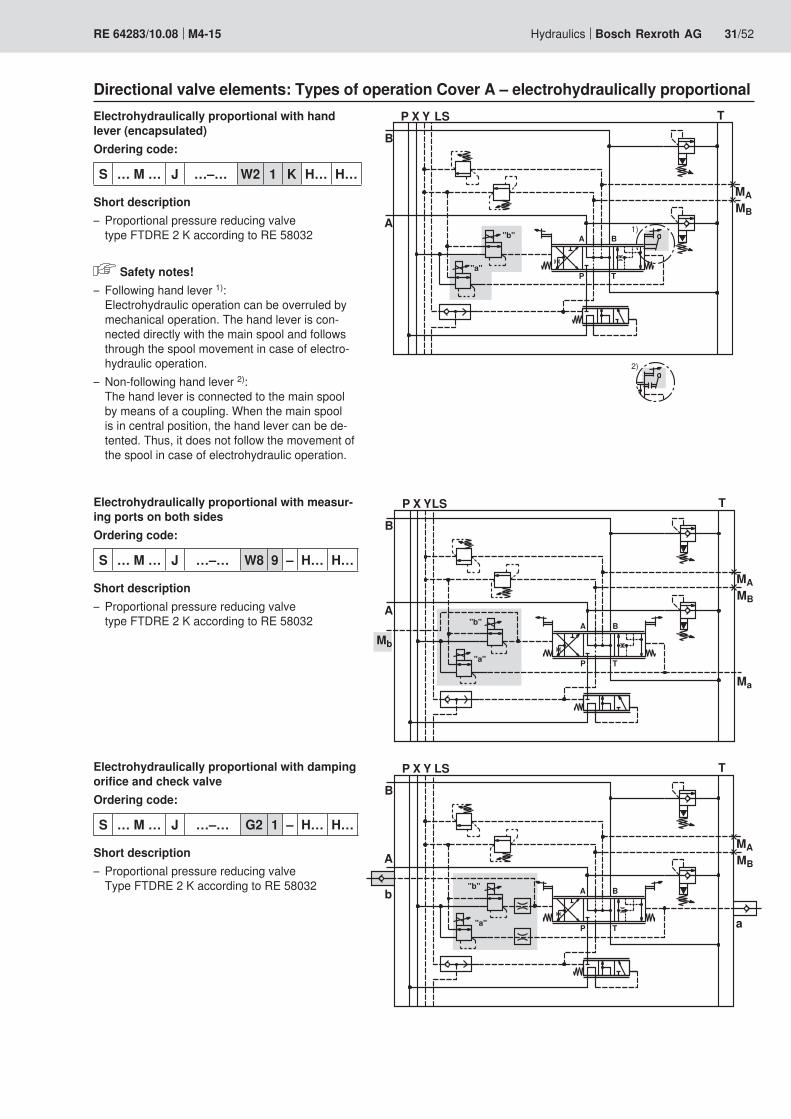
Electrohydraulically proportional with hand lever (encapsulated)Ordering code:
S … M … J …–… W2 1 K H… H…
Short descriptionProportional pressure reducing valve –type FTDRE 2 K according to RE 58032
Safety notes!Following hand lever – 1): Electrohydraulic operation can be overruled by mechanical operation. The hand lever is con-nected directly with the main spool and follows through the spool movement in case of electro-hydraulic operation.Non-following hand lever – 2): The hand lever is connected to the main spool by means of a coupling. When the main spool is in central position, the hand lever can be de-tented. Thus, it does not follow the movement of the spool in case of electrohydraulic operation.
Directional valve elements: Types of operation Cover A – electrohydraulically proportional
Electrohydraulically proportional with measur-ing ports on both sidesOrdering code:
S … M … J …–… W8 9 – H… H…
Short descriptionProportional pressure reducing valve –type FTDRE 2 K according to RE 58032
Electrohydraulically proportional with damping orifice and check valveOrdering code:
S … M … J …–… G2 1 – H… H…
Short descriptionProportional pressure reducing valve –Type FTDRE 2 K according to RE 58032

����
�
��
�
� �
� ����
���
����
� �
� �
����
�� ��
�
��
�
���
���
32/52 Bosch Rexroth AG Hydraulics M4-15 RE 64283/10.08
Directional valve elements: Types of operation Cover A – electrohydraulically proportionalTechnical data FTDRE 2K (see also RE 58032)
electricalType of voltage Direct voltageNominal voltage of the amplifier V 12 24Maximum control current A 1.8 0.8Coilresistance(20℃) Ω 2.4 12Duty cycle (with amplifier) % 100Electric connection See order detailsProtection class according to DIN 40050-9
– Solenoid IP 69K– Electric connection C4
K40IP 69K 1)
IP 69K 1)
PWM frequency (recommended) 1) Hz 150
1) The PWM frequency is to be optimized depending on the application. In this regard, observe the temperature range of the application.
Recommended plug-in connector see page 33.
Directional valve elements: Types of operation cover A – on-board electronics
Electronic pilot moduleOrdering code:
S … M … J …–… CBA – H… H…
Short descriptionDigital interface, standard –See RE 64815-B –
Electronic pilot module with position sensorOrdering code:
S … M … J …–… CPA – Q Q
Short descriptionDigital interface with directional sensor, –See RE 64815-B –
Note!At request only. Rating by Technical Sales.

Hydraulics Bosch Rexroth AGRE 64283/10.08 M4-15 33/52
All control blocks with EPM2 are supplied with mounted daisy chain cabling and terminal resistance connector. The terminal resistance is mounted to the last section of the block.Recommended cable for connection to the machine electronics:Material number: R917c02724
Directional valve elements: Types of operation cover A – on-board electronicsOpen plug for connec-tion to the machine electronics
Daisy chain Plug with terminal resistance
End elementInlet
element
Directional valve elements: Voltage supply and plug-in connectors
Connector typeSupply voltage Junior Timer
2-pin (AMP)DT04-2P
(Deutsch)24 V 1 812 V 3 9
This information is required only in case of electrohydraulic operation and / or electroproportional pressure limitation.
Recommended plug-in connector for connector type Junior Timer 2-pin (AMP)Plug-in connector for FTDRE… and FTWE… protection class IP 69KMaterial number: R900313533For litz wire cross-sections of 0.5 to 1 mm² and for an isola-tion diameter of the individual seals of 1.2 to 2.1 mmMaterial number: R901022127For litz wire cross-sections of 0.5 to 1 mm² and for an isola-tion diameter of the individual seals of 2.2 to 3 mm
Recommended plug-in connector for Junior Timer 2-pin (AMP)
Note!Plug-in connectors are not included in the scope of supply and need to be ordered separately.
60˚ = K, N
0˚ = L, O
-60˚ = M, P
0˚ = F, H
30˚ = B1, G1
-30˚ = D1, J1
1
2
3
60˚ = B, G
-60˚ = D, J
34/52 Bosch Rexroth AG Hydraulics M4-15 RE 64283/10.08
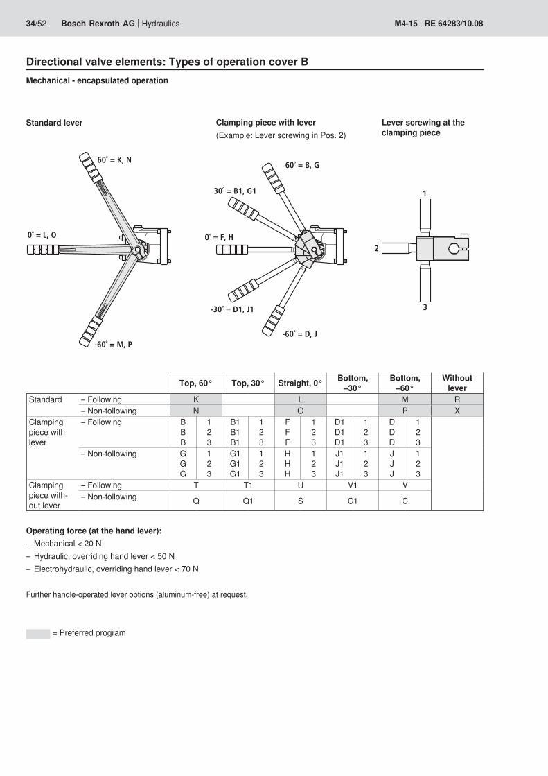
Directional valve elements: Types of operation cover BMechanical - encapsulated operation
Operating force (at the hand lever):Mechanical < 20 N –Hydraulic, overriding hand lever < 50 N –Electrohydraulic, overriding hand lever < 70 N –
Further handle-operated lever options (aluminum-free) at request.
= Preferred program
Standard lever
Top, 60° Top, 30° Straight, 0° Bottom, –30°
Bottom, –60°
Without lever
Standard – Following K L M R– Non-following N O P X
Clamping piece with lever
– Following BBB
123
B1B1B1
123
FFF
123
D1D1D1
123
DDD
123
– Non-following GGG
123
G1G1G1
123
HHH
123
J1J1J1
123
JJJ
123
Clamping piece with-out lever
– Following T T1 U V1 V– Non-following Q Q1 S C1 C
Clamping piece with lever(Example: Lever screwing in Pos. 2)
Lever screwing at the clamping piece

� ���
�
��
�
� �
� ����
���
����
� ���
�
��
�
� �
� ����
���
����
� �� �� ��� ��� ���
������������������������
��
�� ����� ��� ����
�
�
�
�
��
Hydraulics Bosch Rexroth AGRE 64283/10.08 M4-15 35/52
Pressure relief/anti-cavitation valves, adjustableOrdering code:
S … M … J …–… W2 1 – Q H200
Short descriptionAdjustable pressure relief/anti-cavitation valve, pilot –operatedPressure information in bar after H ... require –(3-digit)Example: QH200 – Q: Plug screw for actuator port A H200: Pressure relief/anti-cavitation valves, set to 200 bar for actuator port BThe directional valve is ready for retroactive fitting –of secondary valvesSee RE 64642. –
Directional valve elements: Secondary valves
Feed valvesOrdering code:
S … M … J …–… W2 1 – E E
Short descriptionSee RE 64642. –
Pres
sure
diff
eren
tial in
bar
→
Flow in l/min →
Pressure function
Flow in l/min →
Setti
ng p
ress
ure
in b
ar →
Feed function
��
���
�
��
���
���
��
���
�
����������
��
��
��
��
���
�
����������
��
��
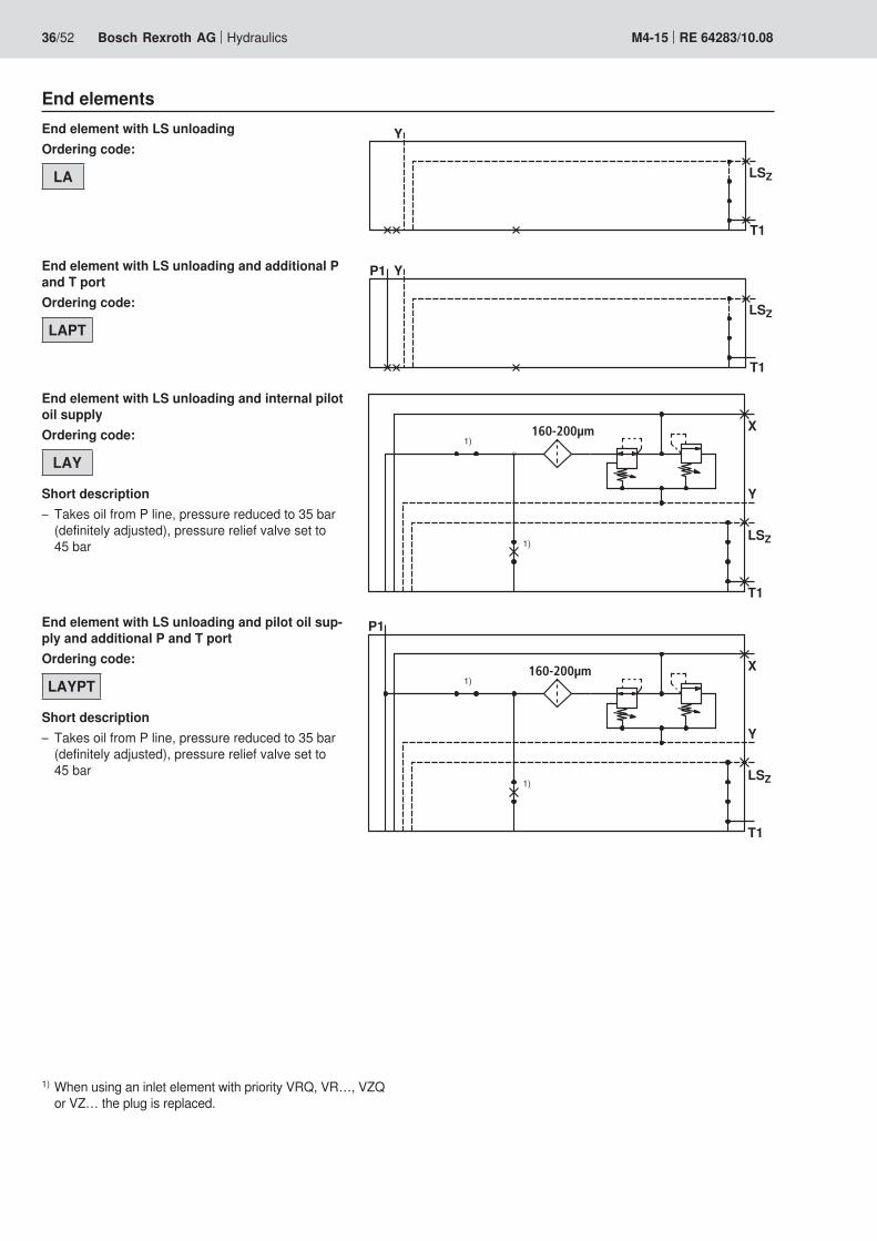
36/52 Bosch Rexroth AG Hydraulics M4-15 RE 64283/10.08
End elementsEnd element with LS unloadingOrdering code:
LA
End element with LS unloading and additional P and T portOrdering code:
LAPT
End element with LS unloading and pilot oil sup-ply and additional P and T portOrdering code:
LAYPT
Short descriptionTakes oil from P line, pressure reduced to 35 bar –(definitely adjusted), pressure relief valve set to 45 bar
1) When using an inlet element with priority VRQ, VR…, VZQ or VZ… the plug is replaced.
End element with LS unloading and internal pilot oil supplyOrdering code:
LAY
Short descriptionTakes oil from P line, pressure reduced to 35 bar –(definitely adjusted), pressure relief valve set to 45 bar
��
���
� �
���������
��
���
� �
���������
��
��
���
�
��
���
���
��
���
�
������ ��������� ������
��
��
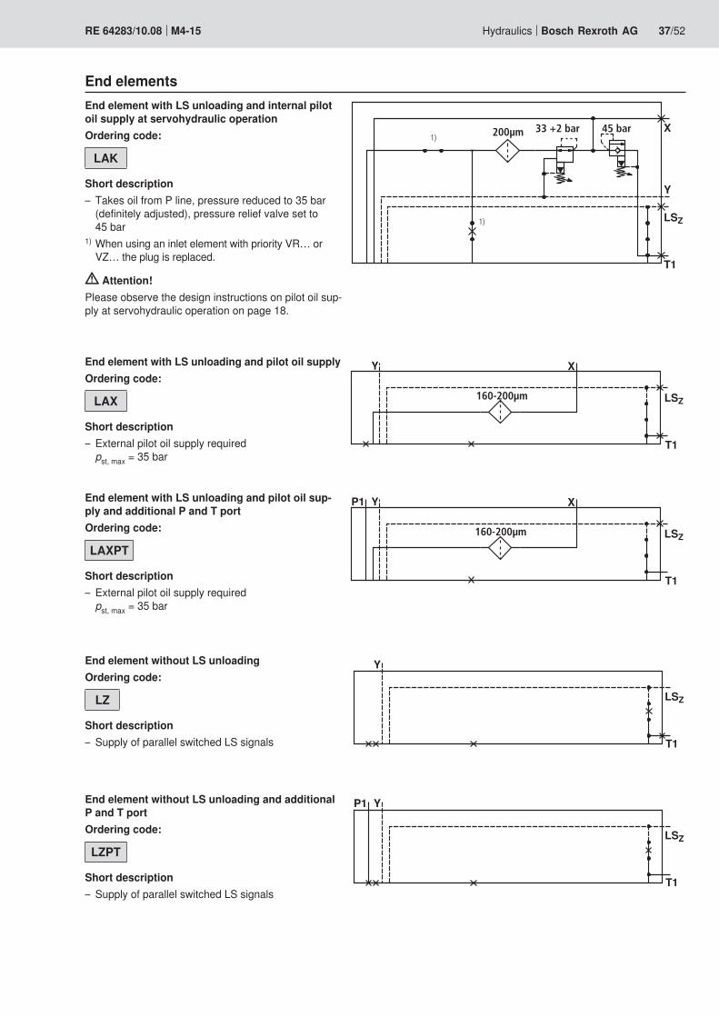
Hydraulics Bosch Rexroth AGRE 64283/10.08 M4-15 37/52
End elements
End element with LS unloading and pilot oil supplyOrdering code:
LAX
Short descriptionExternal pilot oil supply required –pst, max = 35 bar
End element with LS unloading and pilot oil sup-ply and additional P and T portOrdering code:
LAXPT
Short descriptionExternal pilot oil supply required –pst, max = 35 bar
End element without LS unloadingOrdering code:
LZ
Short descriptionSupply of parallel switched LS signals –
End element without LS unloading and additional P and T portOrdering code:
LZPT
Short descriptionSupply of parallel switched LS signals –
End element with LS unloading and internal pilot oil supply at servohydraulic operationOrdering code:
LAK
Short descriptionTakes oil from P line, pressure reduced to 35 bar –(definitely adjusted), pressure relief valve set to 45 bar
1) When using an inlet element with priority VR… or VZ… the plug is replaced.
Attention!Please observe the design instructions on pilot oil sup-ply at servohydraulic operation on page 18.

��
���
�
����������
��
��
��
���
�
����������
��
��
��
��
���
�
������ ��������� ������
��
��
��
���
� �
���������
38/52 Bosch Rexroth AG Hydraulics M4-15 RE 64283/10.08
1) When using an inlet element with priority VRQ, VR…, VZQ or VZ… the plug is replaced.
End element without LS unloading, with pilot oil supplyOrdering code:
LZYShort description
Supply of parallel switched LS signals –Takes oil from P line, pressure reduced to 35 bar –(definitely adjusted), pressure relief valve set to 45 bar
End element without LS unloading, with pilot oil supply and additional P and T portOrdering code:
LZYPTShort description
Supply of parallel switched LS signals –Takes oil from P line, pressure reduced to 35 bar –(definitely adjusted), pressure relief valve set to 45 bar
End elements
End element without LS unloading, with internal pilot oil supply at servohydraulic operationOrdering code:
LZK 2)
Short descriptionSupply of parallel switched LS signals –Takes oil from P line, pressure reduced to 35 bar –(definitely adjusted), pressure relief valve set to 45 bar
Attention! Please observe the design instructions on pilot oil sup-ply at servohydraulic operation on page 18.
End element without LS unloading, with pilot oil supplyOrdering code:
LZX
Short descriptionSupply of parallel switched LS signals –External pilot oil supply required –pst, max = 35 bar

�����
��
���
� �
���������
��
��
� � � ��
�
M4-15
M4-12
�
�� ��
�
Hydraulics Bosch Rexroth AGRE 64283/10.08 M4-15 39/52
End element with external priority portOrdering code:
LVZ
Short descriptionTo connect external priority actuators –
End elementsEnd element without LS unloading, with pilot oil supply and additional P and T portOrdering code:
LZXPT
Short descriptionSupply of parallel switched LS signals –External pilot oil supply required –pst, max = 35 bar
Adapter plate for M4-12 directional valve elementsOrdering code:
L12 Y
Short descriptionWith integrated pilot oil supply –For flanging further M4-12 sections, see datasheet –RE 64276
End element for central inlet element, diversion plateOrdering code:
LU
Diversion plates for central inlet element
End element for central inlet element, diversion plate with additional T portOrdering code:
LUT
End element for central inlet element, diversion plate with additional LS, P and T portOrdering code:
LUPT …
Short descriptionPressure information in bar required (3-digit) –

40/52 Bosch Rexroth AG Hydraulics M4-15 RE 64283/10.08
Unit dimensions: Line connections
Inlet element, lateral Closed center P G 1T G 1LS, LSS, LS1, LSP1,
G 1/4
Y G 1/4M G 1/4S G 1
Open center P G 1T G 1 1/4LS G 1/4X, Y G 1/4M G 1/4
Inlet element, central Closed center P G 1 1/4T G 1 1/4LS G 1/4LSS, LS1, LS2 G 1/4X, Y G 1/4
Priority input P G 1T G 1
Directional valve element with secondary valves A1, B1 G 3/4a1, b1 G 1/4MA, MB G 1/4Ma1, Mb G 1/8
End element P G 3/4T1 G 3/4LS G 1/4LSZ G 1/4X, Y G 1/4
Adapter plate X, Y G 1/4T G 3/4
Fastening screws M10 according to EN ISO 4762 or EN ISO 4014:Property class: 8.8 10.9Fastening torque: 41 ± 2 Nm 60 ± 3 Nm
Connections according to ISO 1179-1
P = PumpP1 = Subordinate connectionA, B = Actuatora, b = Pilot lineT, T1 = TankX = Pilot oil supplyY = Tank, at zero pressureLS = Load-sensing (LS)LSZ = LS supplyLSP1 = LS port subordinate actuatorsLSS = LS priority portM = Pump measuring portMA, MB = Measuring ports LS
pressureMa, Mb = Measuring ports pilot
pressureS = Priority actuators

S
LS
T P
LSS
801070
10113
133
22
83
M10
32 40
3697
102
15
97
130
36
27
133
92
58
903532
38
93
65
88
12.535
M10
130
T P
M
LS
20
29
22
11310
LS
P1
LSP1
T
P
130
83
133
M10
36
1060
Y
4050
98
92
31
61
115
103
17
30
30
30
19
22
1131060 36
10
LSS
LSS
T
P
130
83
97
133
35
98
77 102
97
40
M10
Hydraulics Bosch Rexroth AGRE 64283/10.08 M4-15 41/52
Unit dimensions: Lateral inlet elementsLateral inlet element J Lateral inlet element P
Lateral inlet element VR Lateral inlet element VL

10
22
6010
36
133
113
1585
80
90.5
30.5
32 40
130
M10
LS
T
P
30
22
1131060 36
10
133
130
4032
T
P
LS
85
15
97
M10
80
42/52 Bosch Rexroth AG Hydraulics M4-15 RE 64283/10.08
Unit dimensions: Central inlet elementsCentral inlet element JZ Central inlet element VZ
LS XY
T
P
130
M10
3578 12
63
12125
75
153 90
14
64
70
25 40 47
ca. 34 40
105
46 60
18
27
22
133
51
A B
12
33
25,5
48,5
93,5
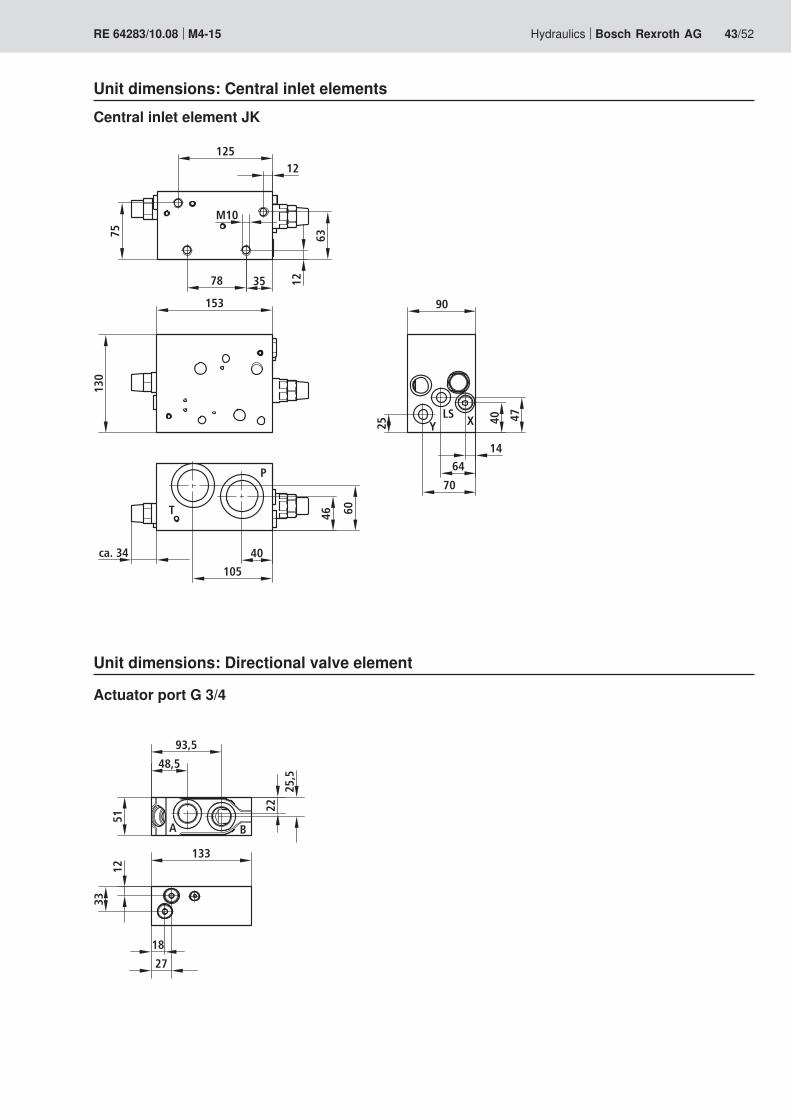
Hydraulics Bosch Rexroth AGRE 64283/10.08 M4-15 43/52
Central inlet element JK
Unit dimensions: Central inlet elements
Unit dimensions: Directional valve element
Actuator port G 3/4

6463
39
56,586
,539
"b"
"a"63
108
86,5
152
169
86135
60˚
230
6463
39
56,586
,539
"b"
"a"63
108
86,5
152
169
86135
60˚
230
44/52 Bosch Rexroth AG Hydraulics M4-15 RE 64283/10.08
Unit dimensions: OperationMechanical / hydraulic operation with standard cover
Ordering code:
… M – …
… H – …
Electrohydraulic operation
Ordering code:
… W . –
Electronic pilot module with hand lever
Ordering code:
… C . A K …
Cover A Cover B
Cover A Cover B
Cover A Cover B

28
20
Y
T1
LSZ
54
40
65
133
130
15
50
30,5 82
,5
20
Y
T1
LSZ
54
40
65
133
130
15
50
28
X
82,5
30,5
22
20
Y
T
LSZ
40
65
133
130
50
28
X
18
30
112
54
82,5
28
28
26
25
Y
T
130
X
7751
153
38
40
52
82
Hydraulics Bosch Rexroth AGRE 64283/10.08 M4-15 45/52
Unit dimensions: End elements for lateral inlet elementOrdering code:
LA
LZ
Ordering code:
LAX
LZX
Ordering code:
LAY
LZY
Ordering code:
L12

22
20
133
130
50
65
100
35
20
133
130
50
65
35
20
133
130
50
65
35
31
75
40 52
46/52 Bosch Rexroth AG Hydraulics M4-15 RE 64283/10.08
Ordering code:
LU
Unit dimensions: End elements for central inlet element
Ordering code:
LVZ
Ordering code:
LUT

2027
22
133
6525
3532
38
88
93
133
T
PA1 B1
A2 B2
A3 B328
4
5151
51
65
3 x
51 =
153
50
130
58
92
90
130
131
31
32
69
162
5445
40
69
261
LSZ
Y T1
M
LS
1
4
10
7
8
5
3
2
8
7
6
9
92,5
4548,5
12,5
30,5
25,5
25,5
82,593,5
Hydraulics Bosch Rexroth AGRE 64283/10.08 M4-15 47/52
Unit dimensions: Control block closed center with lateral inlet element
1 Nameplate2 Inlet element J...
“Closed center”3 Directional valve elements4 End element LA 5 Control cover H (side A) for hy-
draulic operation6 Control cover standard
(side B)7 Stroke limiter8 Secondary valves9 Tie rod
10 Mounting thread 4 x M10; 15 deep
(according to the order example of page 12, dimensions in mm)

36
28
32
22
8
20
2022
133
65
35
T
P
A1 B1
A251
51
LSZ
Y T1
X
48,5
6010
10
113
22
99
130
131
5080
50
310
18
13393
5345
69
130
25,5
54133151
40
112
130
454
49
289
4.1
5.2
1
5.13
10
26
9
7
40
B2
9
4.2
92.5
93,5
30,5
97,5
162,
5
26,5
82,5
30
25
85
133
48/52 Bosch Rexroth AG Hydraulics M4-15 RE 64283/10.08
Unit dimensions: Control block closed center with central inlet element(according to the order example of page 13, dimensions in mm)
1 Nameplate2 Central inlet element VZ…
“Closed center” with priority valve3 Directional valve elements
4.1 End element LAY 4.2 Diversion plate LU 5.1 Control cover W (side A) for elec-
trohydraulic operation5.2 Control cover CBA (side A) with
electronic pilot module 6 Control cover K (side B)7 Stroke limiter8 Primary pressure relief valve9 Electro-proportional pressure relief
valve, type KBPS10 Tie rod11 Mounting thread
4 x M10; 15 deep

1276.2
20
25
1523
22
28
133135
440
236
25 78
4698
114
18
85
40
113141
20
48
106
45 30 40 63 75
35
118 44
76 9046
4630
5150
4047
130
344
125 64
63T
P
A1 B1
A2 B2
A3 B3
MP
XLS
1
2
3.1
3.2
4.1
4.2
5 6.1
8
9
157,
5
25,5
48,5
93,5
Hydraulics Bosch Rexroth AGRE 64283/10.08 M4-15 49/52
Unit dimensions: Control block closed center with combined inlet element(according to the order example of page 14, dimensions in mm)
1 Nameplate2 Central inlet element JK…
“Closed center”3.1 Directional valve element M4-153.2 Directional valve element M4-124.1 End element LA 4.2 Diversion plate LU
5 Control cover CBA (side A) with electronic pilot module
6.1 Control cover K (side B)6.2 Control cover standard (side B)
7 Stroke limiter8 Tie rod9 Mounting thread
4 x M10; 15 deep

50/52 Bosch Rexroth AG Hydraulics M4-15 RE 64283/10.08
On-board electronics: Electronic pilot module (EMP2)FunctionThe electronic pilot module controls the flow at the control block M4-15 via an analog or digital electrical signal.An analog (voltage or PWM signal) or digital (CAN bus) input signal is converted by the pilot module into a pilot pressure via two electrohydraulic pressure reducing valves.In case of an analog input signal, each pilot module is con-nected individually to the control electronics of the machine.In case of CAN bus operation, is it possible to loop the electri-cal connection to the next pilot module via a second plug-in connection (daisy chain cabling). The complete valve control block is then connected to the control of the machine via the 4-pin plug of the first pilot module.The electrical connection is realized via a 4-pin plug, type Bosch Kompakt 1.It is also possible to connect further CAN bus units at the out-put of the last pilot module (see also RE 64815-B).
FeaturesTime functions (ramp functions), form of the characteristic curve and increase are parameterizable and can be changed directly during the working cycle via the CAN bus.Various diagnosis functions allow to monitor the fault-free function of the pilot module.The following elements are monitored with the standard version:
Correct reception of a valid command value signal –Stability of the connection to the command value encoder –The adherence to the defined limits of supply voltage –Function of the pilot valves (short-circuit, cable break) –
Malfunctions are indicated in the form of a error code (blink-ing code) via an LED that can be seen from the outside.With the analog module, there is a relay output available as error indicator.With the CAN bus variant, the error code is transferred to the control in the state telegram of the pilot module and can then be analyzed by the control.
Low cabling effort with CAN wiring through daisy chain –Clocked output stages with superimposed dither –Processor-independent watchdog –Selectable time ramps, separated individually for valve –outputs A and B, Open and Close (only for CAN, fixed parameter for analog module)
Electronic pilot module EMP2
Modifiable characteristic curve from linear to progressive –trend separately for A and B (only CAN, fixed parameter for analog module)Linear decline of the characteristic curve, modifiable in op- –eration, and therefore also linear lowering of the complete flow (CAN only, fixed parameter for analog module)Selectable time ramps for shutoff in the error case (only for –analog module)Selectable monitoring limits for operating voltage –Parameterizable via CAN bus –Protection class according to EN 60529 IP 69K – (only with plugged Bosch Kompakt connectors)Condition Monitoring –
Internal saving of temperatures•Internal counting of the operating hours•Internal saving of diagnostic data•
Comprehensive parameterizibility according to the client's –requirements by Rexroth in the factory
OptionsPosition sensor –with measuring port –
Electronic pilot module: Parameter specifications
The form for the parameter specifications can be found in the project planning aid RE 64815-02. It serves for setting the electronic pilot module according to the requirements of the customer ex factory.

����
����
������
���
���
����
� � � �
����
��������
���������
���
� � � �
��� ������
Hydraulics Bosch Rexroth AGRE 64283/10.08 M4-15 51/52
Electronic pilot module: Pin assignmentPin assignment at the Bosch Kompakt plug-in connector
Coding 2 (plug-in connector gray)
Pin assignment at the CAN plug-in connectorConnection via Bosch Kompakt plug coding 1.Via the second Bosch Kompakt plug c oding 2, a connection to the next module or to another CAN participant is possible if CAN operation is used.
Note!Connecting cables and plug-in connectors are not included in the scope of supply and need to be ordered separately (see accessories pages 51, 52).
Attention!Please observe at all times the safety notes of the operat- –ing instructions RE 64815-B.Bosch Rexroth warrants the correct function of the unit as –described in the operating instructions RE 64815-B. With this unit, Bosch Rexroth declines any warranty for the safe operation of the machine or plant of which this unit is a part.
Coding 1 (plug-in connec-
tor black)
Electronic pilot module: Accessories
Material number Type Description Length
Daisy chain cable
R917c02581R917c02599R917c02628
CableCableCable
For the connection of two pilot modules (standard)For the connection of two pilot modulesFor the connection of two pilot modules via central inlet
190 mm240 mm370 mm
Special cable
R9017c05332 Cable with two plug-in connectors, coding 1 (black) 90°
R917c05333 Cable with two plug-in connectors, coding 2 (gray) 90°

Bosch Rexroth AG HydraulicsZum Eisengießer 197816 Lohr am Main, Germany Phone +49 (0) 93 52 / 18-0 Fax +49 (0) 93 52 / 18-23 [email protected] www.boschrexroth.de
© All rights with Bosch Rexroth AG, including applications for property rights. It may not be reproduced or given to third parties without its consent.The data specified only serve to describe the product. Our information cannot be used to derive a particular property or suitability for a specific use. The information conveyed does not relieve the user from making own evaluations and performing own inspections. Please note that our products are subject to a natural process of wear and aging.
52/52 Bosch Rexroth AG Hydraulics M4-15 RE 64283/10.08
Electronic pilot module: Accessories
Material number Type Description Length
Connecting cable
R917c02724R917c04484
CableCable
with one plug-in connector, coding 1 (black)with one plug-in connector, coding 2 (gray)
4,000 mm4,000 mm
Plug-in connectors and connector sets
R917c05459R917c02627
Plug-in connectorPlug-in connector
Coding 1 (black), dummy plugCoding 2 (gray), dummy plug
R917c05458R917c04605
Plug-in connectorPlug-in connector
Coding 1 (black), dummy connector with integrated terminal resistanceCoding 2 (gray), dummy connector with integrated terminal resistance
R900785606 Connector set Bosch Kompakt coding 1 (black)
R900785607 Connector set Bosch Kompakt coding 2 (gray)