LOAD MOMENT INDICATOR iFLEX5 - RW SALES & SERVICES
79
www.hirschmann.com HIRSCHMANN P/N 031-300-190-154 REV G 06/05/2006 LOAD MOMENT INDICATOR iFLEX5 SERVICE MANUAL
Transcript of LOAD MOMENT INDICATOR iFLEX5 - RW SALES & SERVICES

www.hirschmann.com HIRSCHMANN
P/N 031-300-190-154 REV G 06/05/2006
LOAD MOMENT INDICATOR
iFLEX5
SERVICE MANUAL


Service Manual iFLEX5
© Hirschmann Rev. G 06/05/06 190154_G
NOTICE Hirschmann Electronics, Inc. makes no warranty of any kind with regard to this material, including, but not limited to, the implied warranties of merchantability and/or its fitness for a particular purpose. Hirschmann will not be liable for errors contained in this manual or for incidental or consequential damages in connection with the furnishing, performance, or use of this manual. This document contains proprietary information, which is protected by copyright, and all rights are reserved. No part of this document may be photocopied, reproduced, or translated to another language without the prior written consent of Hirschmann. Hirschmann reserves proprietary rights to all drawings, photos and the data contained therein. The drawings, photos and data are confidential and cannot be used or reproduced without the written consent of Hirschmann. The drawings and/or photos are subject to technical modification without prior notice. All information in this document is subject to change without notice. MANUAL REVISIONS
REV DATE NAME DESCRIPTION - 04/10/02 CSH ECN 02-122 A 06/03/02 MO ECN 02-122 B 06/15/02 MO ECN 02-122 C 06/24/02 MO ECN 02-122 D 07/01/02 MO ECN 02-122 E 12/04/02 CSH ECN 02-179 F 07/29/03 CSH ECN 03-088 G 06/05/06 SB ECN 05-110
© 2006 Hirschmann, Chambersburg, PA 17201, USA
Service Manual iFLEX5
© Hirschmann Rev. G 06/05/06 190154_G
TABLE OF CONTENTS 1 General Information ....................................................................................................................1 2 Warnings ......................................................................................................................................1 3 Description Of The System ........................................................................................................2
3.1 DESCRIPTION OF SYSTEM FUNCTION............................................................................................. 2 3.2 DESCRIPTION OF A CAN BUS SYSTEM .......................................................................................... 2 3.3 DESCRIPTION OF THE SYSTEM COMPONENTS................................................................................ 3
4 What’s Wrong?............................................................................................................................4 4.1 I HAVE AN ERROR CODE INDICATED ON THE CONSOLE .................................................................... 4 4.2 THE DISPLAYED ANGLE DOES NOT MATCH THE ACTUAL BOOM ANGLE............................................. 4 4.3 THE DISPLAYED LENGTH DOES NOT MATCH THE ACTUAL BOOM LENGTH ......................................... 4 4.4 THE DISPLAYED SLEWING DOES NOT MATCH THE ACTUAL SLEWING ANGLE..................................... 4 4.5 THE DISPLAYED LOAD DOES NOT MATCH THE ACTUAL LOAD........................................................... 4 4.6 THE CONSOLE DISPLAY IS BLANK .................................................................................................. 4 4.7 I HAVE AN A2B PROBLEM ............................................................................................................. 4 4.8 I HAVE A CAN-BUS PROBLEM...................................................................................................... 4 4.9 I NEED TO IDENTIFY A SPARE PART ................................................................................................ 4 4.10 I HAVE NOTICED WATER IN SOME PART OF THE SYSTEM.................................................................. 4
5 Angle Sensing .............................................................................................................................5 5.1 ANGLE SENSING ERROR - FLOW CHART ......................................................................................... 6
6 Length Sensing ...........................................................................................................................8 6.1 LENGTH SENSING ERROR - FLOW CHART...................................................................................... 9
7 Pressure Sensing ......................................................................................................................11 7.1 PRESSURE SENSING ERROR - FLOW CHART.................................................................................. 11
8 Slewing Sensing........................................................................................................................12 8.1 SLEW SENSING ERROR - FLOW CHART ......................................................................................... 13
9 Load sensing .............................................................................................................................14 9.1 LOAD SENSING ERROR - FLOW CHART.......................................................................................... 14
10 No console display....................................................................................................................15 11 A2B Problem..............................................................................................................................16 12 cann-bus communication.........................................................................................................17
12.1 E61 ........................................................................................................................................... 17 12.1.1 E61 - Flow Chart ............................................................................................................... 18
12.2 E62 ........................................................................................................................................... 19 12.3 E63 ........................................................................................................................................... 19 12.4 E64 ........................................................................................................................................... 19
12.4.1 E64 - Flow Chart ............................................................................................................... 20 12.5 E65 ........................................................................................................................................... 20
13 Troubleshooting a sensor problem using the display...........................................................21 14 iFLEX5 Boom Control System (BCS).......................................................................................24
14.1 RT9000E / RT800E BASICS....................................................................................................... 24 14.1.1 Terminology: ..................................................................................................................... 24 14.1.2 Components: .................................................................................................................... 24 14.1.3 Manual / Auto Mode:......................................................................................................... 24
14.2 TELE SEQUENCE: ....................................................................................................................... 26 14.3 IFLEX5 BCS DIGITAL INPUTS: ................................................................................................... 26 14.4 RT9000E / RT800E IFLEX5 BCS DIGITAL OUTPUTS: ................................................................ 27

Service Manual iFLEX5
© Hirschmann Rev. G 06/05/06 190154_G
14.5 IFLEX5 BCS ANALOG INPUTS AND PWM OUTPUTS: .................................................................. 29 14.6 IFLEX5 BCS TEST DISPLAY: ..................................................................................................... 31 14.7 BOOM OUT OF SEQUENCE:......................................................................................................... 32 14.8 TELE ROD DRAIN VALVE: ........................................................................................................... 32 14.9 TELE TWO STAGE RELIEF VALVE: .............................................................................................. 32 14.10 HYDRAULIC LUFFING BOOM EXTENSION: .............................................................................. 33
15 Drawings ....................................................................................................................................34 15.1 COMPONENTS OF THE LMI SYSTEM PAT IFLEX5........................................................................ 34 15.2 BLOCK DIAGRAM........................................................................................................................ 35 15.3 ELECTRICAL SYSTEM DIAGRAM STANDARD SYSTEM ................................................................... 36
15.3.1 Central Unit to Crane and Console Wiring Diagram ..................................................... 36 15.3.2 Cable Reel (length/angle sensor) Wiring Diagram ........................................................ 37 15.3.3 Boom Extension Anti-two Block Wiring Diagram ......................................................... 38
15.4 MAIN CENTRAL UNIT CONNECTOR .............................................................................................. 38 15.5 ELECTRICAL SYSTEM DIAGRAM BOOM CONTROL SYSTEM........................................................... 39
15.5.1 Central Unit to Crane Interface Wiring Diagram ............................................................ 39 15.5.2 Console and Sensor Wiring Diagram ............................................................................. 40 15.5.3 Cable Reel (LWG520/0002) Wiring Diagram................................................................... 42 15.5.4 Luffer Extension Wiring Diagram.................................................................................... 43
16 Spare Part Listings ...................................................................................................................44 16.1 CENTRAL UNIT, IFLEX5 PART NO. 021-020-060-003........................................................... 44 16.2 GRAPHIC CONSOLE ASSY, VERTICAL PART NO. 050-350-061-356 ................................. 45 16.3 GRAPHIC CONSOLE ASSY, PART NO. 050-350-061-376 ................................................... 46 16.4 CABLE REEL, LWG508 PART NO. 068-508-060-001............................................................ 47 16.5 CABLE REEL, LWG521 PART NO. 068-521-060-002............................................................ 49 16.6 CABLE REEL, LWG152 PART NO. 067-152-060-056............................................................ 50 16.7 PRESSURE TRANSDUCER BLOCK, DAV314/0014 PART NO. 044-314-060-014 ........................ 51 16.8 CABLE ASSEMBLY 11M, PART NO. 031-010-101-007.......................................................... 51 16.9 WIRING HARNESS STANDARD, PART NO. 031-010-100-549 ............................................. 51 16.10 WIRING HARNESS BOOM CONTROL, PART NO. 031-010-100-554 .............................. 52 16.11 CABLE ASSEMBLY, 14M PART NO. 031-010-100-555 ................................................... 52 16.12 TRS05 REPEATER, RADIO WINDSPEED KIT 031-300-104-087 ..................................... 53
17 Service Screen For Sensor Calibration...................................................................................54 17.1 ACTIVATING THE SERVICE SCREEN FOR SENSOR CALIBRATION................................................... 54 17.2 ZERO-SETTING THE TRANSDUCER INPUTS .................................................................................. 55 17.3 ZERO-SETTING THE SLEWING INPUTS ............................................................................... 55 17.4 LENGTH SENSOR CALIBRATION PROCEDURE .............................................................................. 56
17.4.1 Cable Reel LWG508 Adjustment Procedure .................................................................. 56 17.4.2 Length Sensor Adjustment Procedure........................................................................... 57 17.4.3 Cable Reel Length Cable Replacement Procedure ....................................................... 58
17.5 ANGLE SENSOR CALIBRATION PROCEDURE................................................................................ 59 17.6 ZERO-SETTING THE SLEW POTENTIOMETER ............................................................................... 61
18 Error Codes ...............................................................................................................................62 19 Troubleshooting Moisture........................................................................................................72
19.1 WATER INGRESS ........................................................................................................................ 72 19.2 CONDENSATION ......................................................................................................................... 73

General Information
© Hirschmann Rev. G 06/05/06 190154_G
1
1 GENERAL INFORMATION This service manual is designed to assist a service or maintenance person in identifying system problem areas or malfunctions. A digital voltmeter with the capability to measure current will be required, along with standard maintenance and service tools. NOTE: Knowledge of how to use a voltmeter to measure both voltage and current is assumed. REFERENCE: For system operation, refer to the consoles operator’s manual 031-300-190-147.
2 WARNINGS The LMI is an operational aid that warns a crane operator of approaching overload conditions and over hoist conditions that could cause damage to equipment and personnel. The device is not, and shall not be, a substitute for good operator judgment, experience and use of accepted safe crane operating procedures. The responsibility for the safe crane operation shall remain with the crane operator who shall ensure that all warnings and instructions supplied are fully understood and observed. Prior to operating the crane, the operator must carefully and thoroughly read and understand the information in this manual to ensure that he knows the operation and limitations of indicator and crane. Proper functioning depends upon proper daily inspection and observance of the operating instructions set forth in this manual. Refer to Section 6. Pre-Operation Inspection and Calibration Verification of the operator’s manual.
The LMI can only work correctly, if all adjustments have been properly set. For correct adjustment, the operator has to answer thoroughly and correctly all questions asked during the setup procedure in accordance with the real rigging state of the crane. To prevent material damage and serious or even fatal accidents, the correct adjustment of the LMI has to be ensured before starting the crane operation.

Service Manual iFLEX5
© Hirschmann Rev. G 06/05/06 190154_G
2
3 DESCRIPTION OF THE SYSTEM 3.1 DESCRIPTION OF SYSTEM FUNCTION The iFLEX5 system is a CAN bus system made up of a central microprocessor unit, operating console, length/angle sensor, pressure transducers, and anti-two block switches. All components and sensors are equipped with CAN bus controllers. The PAT Load Moment Indicator system operates on the principle of reference/real comparison. The real value, resulting from the pressure measurement is compared with the reference data, stored in the central processor memory and evaluated in the microprocessor. When limits are reached, an overload warning signal is generated at the operator’s console. At the same time, the aggravating crane movements, such as hoist up, telescope out and boom down, will be stopped. The fixed data regarding the crane, such as capacity charts, boom weights, centers of gravity and dimensions are stored in memory chips in the central processor unit. This data is the reference information used to calculate the operating conditions. Boom length and boom angle are registered by the length/angle sensor, mounted inside the cable reel, which is mounted on the boom. The boom length is measured by the cable reel cable, which also serves as an electrical conductor for the anti two-block switches. The crane load is measured by pressure transducer block attached to the piston and rod side of the hoist cylinders. The interactive user guidance considerably simplifies the input of operating modes as well as the setting of geometry limit values. 3.2 DESCRIPTION OF A CAN BUS SYSTEM CAN stands for “Controller Area Network”. Its intended use is as a serial bus system for a network of controllers. Each controller connected through a CAN chip is called a "node" and is mostly used to acquire data from a sensor. All nodes are connected to a common bus and all nodes are able to simultaneously read the data on that bus. Also, all nodes are able to transmit data on that bus however only one node at a given time has write access to the bus. If the message is relevant, it will be processed; otherwise it is ignored. The unique identifier also determines the priority of the message. The lower the numerical value of the identifier, the higher the priority. The cable bus is a twisted pair of shielded wire. Data can be transmitted in blocks from 0-8 bytes at a maximum transfer rate of 1 Mbit/s for networks up to 40 meters. For longer network distances the maximum transfer rate must be reduced to 50 Kbit/s for a 1 km network distance. CAN will operate in extremely harsh environments and the extensive error checking mechanisms ensure that any transmission errors are detected.

Description Of The System
© Hirschmann Rev. G 06/05/06 190154_G
3
3.3 DESCRIPTION OF THE SYSTEM COMPONENTS Pressure Transducer: The pressure transducer converts hydraulic pressure into an electric signal. A pressure transducer block houses two transducers, CAN bus converter board, and two bus connectors. One pressure transducer is connected to the piston side of the lift cylinder and the other to the rod side. The Length-Angle Transducer: The length-angle sensor (LWG), often referred to as the “cable reel”, is a combination of two transducers in one box, installed on the base section of the boom. It measures the length and the angle of the boom.
A reeling drum drives a potentiometer, which is the length transducer. Part of the length transducer circuit is the length cable on the drum, which is a multi-conductor cable. It is connected to the anti-two-block switch at the boom head and to a slip ring body in the LWG. The angle transducer is a potentiometer driven by a weighted pendulum that is oil damped. Both length and angle transducer are connected to a CAN bus controller board, which is connected to the bus system. Anti-Two-Block Switch: The anti-two-block switch monitors the load block and it’s relationship with the head of the boom. In working condition the switch is closed. When the load block strikes the weight the circuit opens, disengaging a relay output to the lock out solenoid valves, where applicable. To check the cable for damage, (short circuit to ground) there is a 4.7k resistor between ground and the contact of the switch, to give a signal back to the central unit. The weight at the anti-two-block switch keeps the switch closed until the load block strikes it. Console: The graphic console displays all geometrical information such as length and angle of main boom, working radius and head height of the boom. It also displays the actual load and the maximum load permitted by load chart. Furthermore, it has an alarm horn, a warning light for overload, and a pre-warning light. The graphic display allows for a simple interactive configuration setup, as well as sensor calibration (zero adjustment), and troubleshooting sensor output screen. The console has a warning light for anti-two-block conditions and an override switch for overload or anti-block condition. Refer to Operator’s Handbook for detailed operation of the console. Central Unit: Inside the central unit there is a CPU and connection board. The board has a hard mounted connector for power, ground, bus controller, and slew indication. The board has a green LED, indicating relay energized and a communication LED that flashes through red, yellow, and green colors. Slew Potentiometer: This component is not supplied by PAT/Hirschmann. It is part of the electrical swivel (slip ring assembly). The potentiometer has two wipers which are used to determine the slewing angle (rotational positioning) of the super structure in relation to the carrier. The slew input to the central unit is not a CAN signal, but rather two 4..20mA analog signals.
Service Manual iFLEX5
© Hirschmann Rev. G 06/05/06 190154_G
4
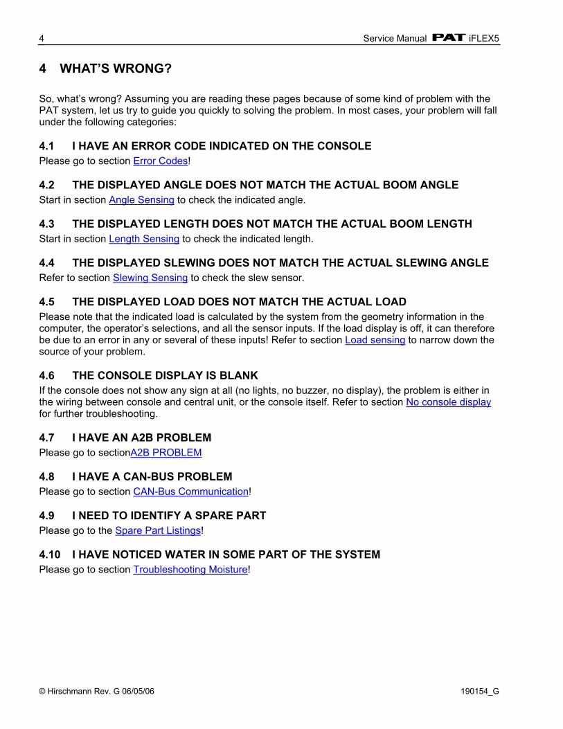
4 WHAT’S WRONG? So, what’s wrong? Assuming you are reading these pages because of some kind of problem with the PAT system, let us try to guide you quickly to solving the problem. In most cases, your problem will fall under the following categories: 4.1 I HAVE AN ERROR CODE INDICATED ON THE CONSOLE Please go to section Error Codes! 4.2 THE DISPLAYED ANGLE DOES NOT MATCH THE ACTUAL BOOM ANGLE Start in section Angle Sensing to check the indicated angle. 4.3 THE DISPLAYED LENGTH DOES NOT MATCH THE ACTUAL BOOM LENGTH Start in section Length Sensing to check the indicated length. 4.4 THE DISPLAYED SLEWING DOES NOT MATCH THE ACTUAL SLEWING ANGLE Refer to section Slewing Sensing to check the slew sensor. 4.5 THE DISPLAYED LOAD DOES NOT MATCH THE ACTUAL LOAD Please note that the indicated load is calculated by the system from the geometry information in the computer, the operator’s selections, and all the sensor inputs. If the load display is off, it can therefore be due to an error in any or several of these inputs! Refer to section Load sensing to narrow down the source of your problem. 4.6 THE CONSOLE DISPLAY IS BLANK If the console does not show any sign at all (no lights, no buzzer, no display), the problem is either in the wiring between console and central unit, or the console itself. Refer to section No console display for further troubleshooting. 4.7 I HAVE AN A2B PROBLEM Please go to sectionA2B PROBLEM 4.8 I HAVE A CAN-BUS PROBLEM Please go to section CAN-Bus Communication! 4.9 I NEED TO IDENTIFY A SPARE PART Please go to the Spare Part Listings! 4.10 I HAVE NOTICED WATER IN SOME PART OF THE SYSTEM Please go to section Troubleshooting Moisture!

Angle Sensing
© Hirschmann Rev. G 06/05/06 190154_G
5
5 ANGLE SENSING The System measures the angle of the main boom of the machine with an angle sensor. The angle sensor is contained within the cable reel, located on the left side of the main boom. Block Diagram The signal runs from the angle sensor to the Can-Bus converter board, both located in the cable reel. From there, it travels as digital information on the CAN-Bus to the pressure transducer, which acts as a T-connector to the main CAN-Bus running to the central unit. So, what do you do when you are having a problem with your angle read-out? Start by verifying the angle display. Refer to the section “Troubleshooting A Sensor Problem Using The Display” to call up the sensor signal on your console display. The CAN-Bus is digital and as such will either transmit the signal correctly or not at all. If your readings are off, you have to determine what is causing the problem (reference the following flow charts). CAN-Bus electronics in cable reel. The angle sensor has a potentiometer built in that is driven by a pendulum. As the angle changes, so will the pendulum and with it the potentiometer’s axle. The converter board supplies a constant voltage of 5V to the angle sensor and in return monitors the voltage of the potentiometer. The terminal used is X21. The angle sensor is connected as follows: Terminal X21 1 + 5V 3 Signal 5 GND
Pressure Transducer
iFLEX5
CU
Angle
Sensor
CAN-Bus Converter
Cable Reel
LED
X21 (angle)
X20 (length)
X14 (A2B)
X1 (CAN)
Service Manual iFLEX5
© Hirschmann Rev. G 06/05/06 190154_G
6
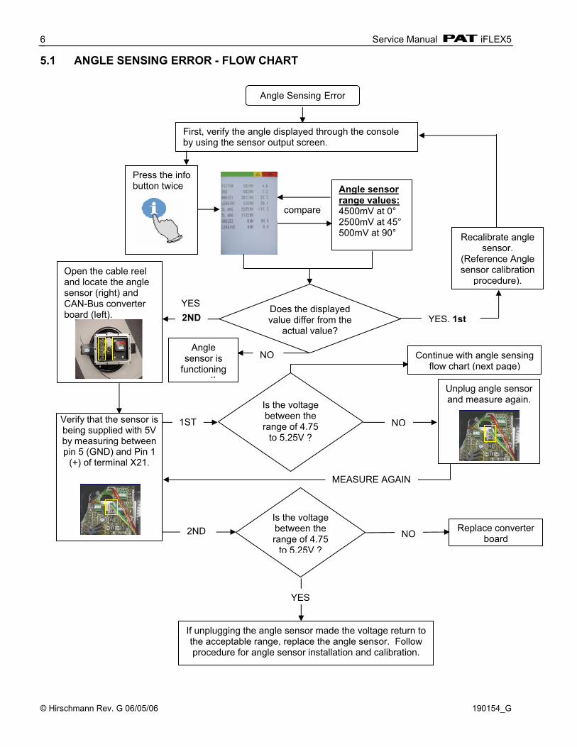
5.1 ANGLE SENSING ERROR - FLOW CHART
Angle Sensing Error
First, verify the angle displayed through the console by using the sensor output screen.
Press the info button twice
Angle sensor is
functioning correctl
Angle sensor range values: 4500mV at 0° 2500mV at 45° 500mV at 90°
Does the displayed value differ from the
actual value?
Open the cable reel and locate the angle sensor (right) and CAN-Bus converter board (left).
Verify that the sensor is being supplied with 5V by measuring between pin 5 (GND) and Pin 1
(+) of terminal X21.
Is the voltage between the range of 4.75
to 5.25V ?
Replace converter board
If unplugging the angle sensor made the voltage return to the acceptable range, replace the angle sensor. Follow procedure for angle sensor installation and calibration.
compare
YES
YES
NO
NO
Is the voltage between the range of 4.75
to 5.25V ?
1ST
2ND
MEASURE AGAIN
Continue with angle sensing flow chart (next page)
Unplug angle sensor and measure again.
NO
2ND YES, 1st
Recalibrate angle sensor.
(Reference Angle sensor calibration
procedure).

Angle Sensing
© Hirschmann Rev. G 06/05/06 190154_G
7
Angle Sensor signal varies
Ensure the angle sensor returns a voltage between 1.875V at 90° and 3.125V at 0°
Does the indicated angle vary by more than +/- 0.25° from the actual angle?
Replace converter board.
If this angle varies significantly from your actual angle,
replace the angle sensor. YES
Ensure correct software has been installed and crane operator is not in
NO
Verify the voltage by measuring
Between Pin 5 (GND) and Pin3(signal) of terminal X21.
Angle Sensor Signal On Pin 3: Angle Voltage 90 1.875 75 2.083 60 2.292 45 2.500 30 2.708 15 2.917 0 3.125 Note: Actual voltages will vary slightly.
Note: If you need to determine the angle for voltages other than shown above, do so by using the following formula:
Angle (degrees) = 90 degrees – ((Voltage-1.875) * 72)

Service Manual iFLEX5
© Hirschmann Rev. G 06/05/06 190154_G
8
6 LENGTH SENSING The system measures the length of the main boom of the machine with a length sensor. The length sensor is contained within the cable reel, located on the left side of the main boom. Block Diagram
The signal runs from the length sensor to the CAN-Bus converter board, both located in the cable reel. From there, it travels as digital information on the CAN-Bus to the pressure transducer, which acts as a T-connector to the main CAN-Bus running to the central unit. So, what do you do when you are having a problem with your length read-out? Start by verifying the length display. Refer to the section “Troubleshooting A Sensor Problem Using The Display” to call up the sensor signal on your console display. The CAN-Bus is digital and as such will either transmit the signal correctly or not at all. If your readings are off, you have to determine what is causing the problem (reference the following flow charts). CAN-Bus electronics in cable reel. The length sensor has a potentiometer built in that is driven by a gear drive from the cable drum. As the length changes, the cable drum will turn and with it the potentiometer’s axle. The converter board supplies a voltage of about 4.7V to the length potentiometer and in return monitors the output voltage of the potentiometer. The terminal used is X20. The length sensor is connected as follows: Terminal X20 1 + (~ 4.8V) 3 Signal 5 - (~ 0.2V)
Pressure Transducer
iFLEX5
CU
Cable Reel
Length Sensor
CAN-Bus Converter
LED
X21 (angle)
X20 (length)
X14 (A2B)
X1 (CAN)

Length Sensing
© Hirschmann Rev. G 06/05/06 190154_G
9
6.1 LENGTH SENSING ERROR - FLOW CHART
Length Sensing Error
First, verify the length displayed through the console is off by using the sensor output screen.
Press the info button twice
Length sensor is functioning correctly.
Does the displayed value differ from the
actual value?
Open the cable reel and locate the length
sensor (right) and CAN-Bus converter
board (left).
Does the indicated length vary
significantly from the actual length (more
than 0.3 feet)?
Replace length sensor.
Proceed to next length sensing flow chart.
NO YES
Ensure the cable reel has
5-8 turns of preloading on
the reel.
Fully retract the boom and turn the screw of the length potentiometer with a small screwdriver counter-clockwise to a soft stop, bringing the sensor voltage to 0V (+/- 0.1 Volt).
Measure voltage between Pin 5 (-) and Pin 3 (signal)
of terminal X20 and compare.
Return to the indication screen and again compare the indicated and actual length.
YES
NO
Press the info button twice
Service Manual iFLEX5
© Hirschmann Rev. G 06/05/06 190154_G
10
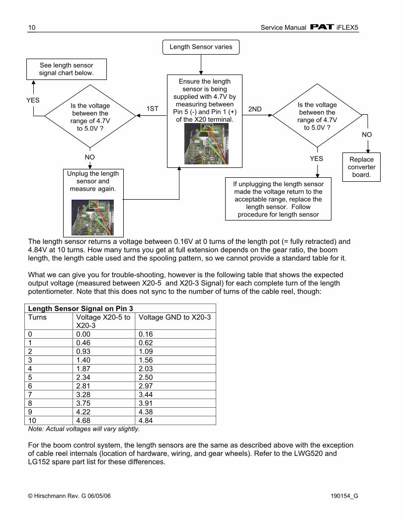
The length sensor returns a voltage between 0.16V at 0 turns of the length pot (= fully retracted) and 4.84V at 10 turns. How many turns you get at full extension depends on the gear ratio, the boom length, the length cable used and the spooling pattern, so we cannot provide a standard table for it. What we can give you for trouble-shooting, however is the following table that shows the expected output voltage (measured between X20-5 and X20-3 Signal) for each complete turn of the length potentiometer. Note that this does not sync to the number of turns of the cable reel, though: Length Sensor Signal on Pin 3 Turns Voltage X20-5 to
X20-3 Voltage GND to X20-3
0 0.00 0.16 1 0.46 0.62 2 0.93 1.09 3 1.40 1.56 4 1.87 2.03 5 2.34 2.50 6 2.81 2.97 7 3.28 3.44 8 3.75 3.91 9 4.22 4.38 10 4.68 4.84 Note: Actual voltages will vary slightly. For the boom control system, the length sensors are the same as described above with the exception of cable reel internals (location of hardware, wiring, and gear wheels). Refer to the LWG520 and LG152 spare part list for these differences.
Length Sensor varies
Replace converter
board. If unplugging the length sensor made the voltage return to the acceptable range, replace the
length sensor. Follow procedure for length sensor
YES
NO
1ST 2ND
Ensure the length sensor is being
supplied with 4.7V by measuring between
Pin 5 (-) and Pin 1 (+) of the X20 terminal.
Is the voltage between the range of 4.7V
to 5.0V ?
See length sensor signal chart below.
YES
NO
Unplug the length
sensor and measure again.
Is the voltage between the range of 4.7V
to 5.0V ?
Pressure Sensing
© Hirschmann Rev. G 06/05/06 190154_G
11
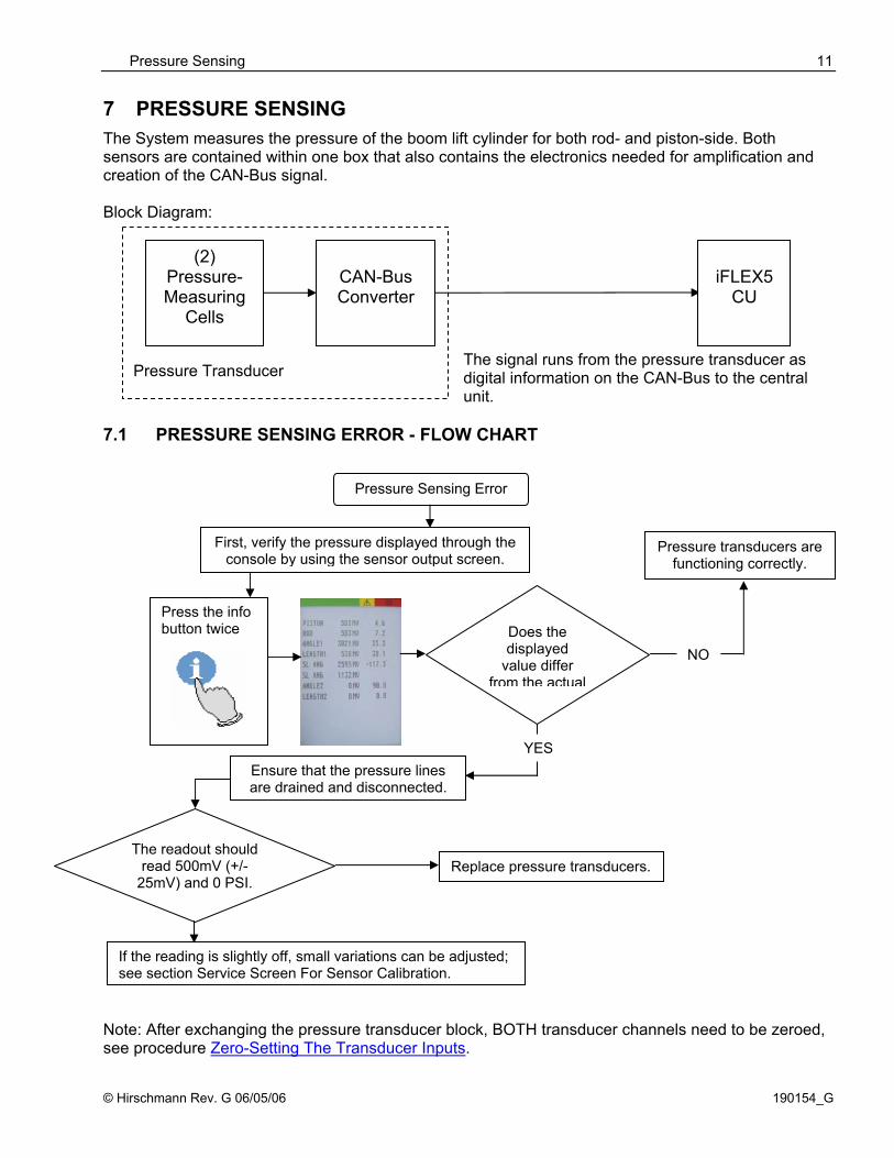
7 PRESSURE SENSING The System measures the pressure of the boom lift cylinder for both rod- and piston-side. Both sensors are contained within one box that also contains the electronics needed for amplification and creation of the CAN-Bus signal. Block Diagram:
The signal runs from the pressure transducer as digital information on the CAN-Bus to the central unit.
7.1 PRESSURE SENSING ERROR - FLOW CHART Note: After exchanging the pressure transducer block, BOTH transducer channels need to be zeroed, see procedure Zero-Setting The Transducer Inputs.
iFLEX5
CU
Pressure Transducer
(2) Pressure- Measuring
Cells
CAN-Bus Converter
Pressure Sensing Error
First, verify the pressure displayed through the console by using the sensor output screen.
Press the info button twice
Pressure transducers are functioning correctly.
Does the displayed
value differ from the actual
The readout should read 500mV (+/-
25mV) and 0 PSI.
If the reading is slightly off, small variations can be adjusted; see section Service Screen For Sensor Calibration.
NO
Ensure that the pressure lines are drained and disconnected.
Replace pressure transducers.
YES
Service Manual iFLEX5
© Hirschmann Rev. G 06/05/06 190154_G
12
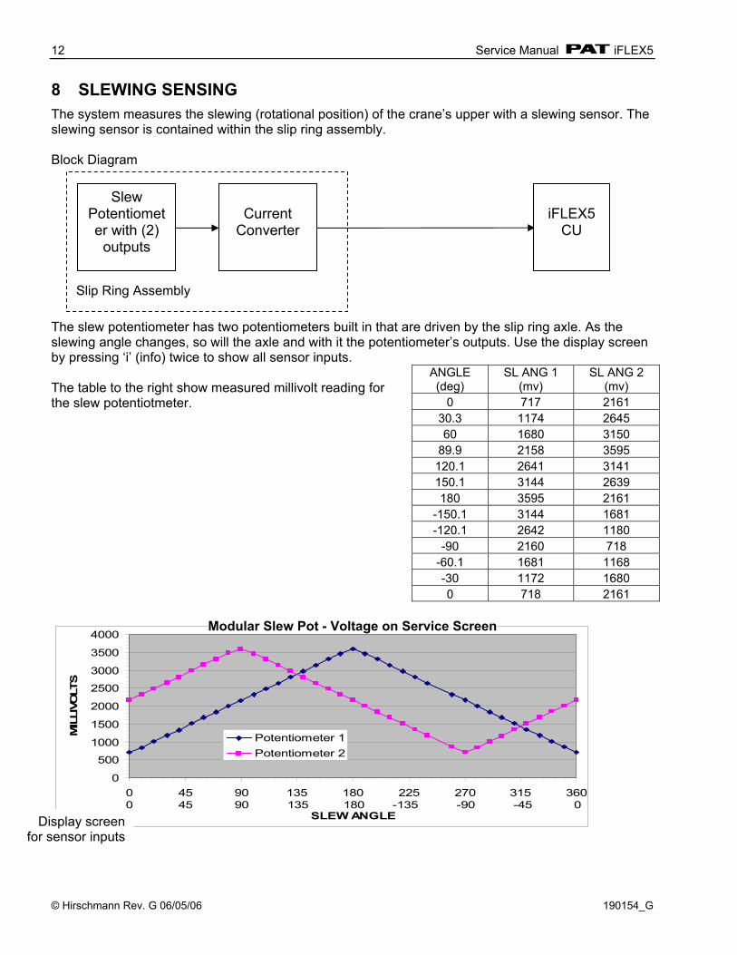
8 SLEWING SENSING The system measures the slewing (rotational position) of the crane’s upper with a slewing sensor. The slewing sensor is contained within the slip ring assembly. Block Diagram
The slew potentiometer has two potentiometers built in that are driven by the slip ring axle. As the slewing angle changes, so will the axle and with it the potentiometer’s outputs. Use the display screen by pressing ‘i’ (info) twice to show all sensor inputs. The table to the right show measured millivolt reading for the slew potentiotmeter.
0
500
1000
1500
2000
2500
3000
3500
4000
0 45 90 135 180 225 270 315 360
SLEW ANGLE
MIL
LIVO
LTS
Potentiometer 1Potentiometer 2
0 45 90 135 180 -135 -90 -45 0
ANGLE (deg)
SL ANG 1 (mv)
SL ANG 2 (mv)
0 717 2161 30.3 1174 2645 60 1680 3150
89.9 2158 3595 120.1 2641 3141 150.1 3144 2639 180 3595 2161
-150.1 3144 1681 -120.1 2642 1180
-90 2160 718 -60.1 1681 1168 -30 1172 1680 0 718 2161
iFLEX5
CU
Slip Ring Assembly
Slew Potentiometer with (2)
outputs
Current
Converter
Modular Slew Pot - Voltage on Service Screen
Display screen for sensor inputs

Slewing Sensing
© Hirschmann Rev. G 06/05/06 190154_G
13
M odular Sle w Pot - Output Curre nts
0
4
8
12
16
20
24
0 90 180 270 360
De gre es
mA
mA 2
mA 3
The converter board is supplied with 12V from the central unit. The potentiometer and the board output two signals between 4 and 20mA that go to the central unit. You can measure them at the 12-pin crane interface connector. 8.1 SLEW SENSING ERROR - FLOW CHART
(When the crane is over front, you should see about 4mA in one channel (wire #2) and 12mA in the other channel (wire #3)).
Slew Sensing Error
First, verify the slew angle displayed through the console by using the sensor output screen.
Press the info button twice
Slew potentiometer is functioning correctly.
Does the displayed value differ from the actual value?
The slew unit output can be found on pins 8 and 9. In order to measure current, however, you must disconnect a pin and
measure in line (between the cable from the slew unit and the central unit). *The two outputs will vary as shown in chart below.
NO
YESEnsure that the slew pot unit is supplied with crane voltage.
Pin 7 must carry crane voltage and Pin 2 is GND.
You can also leave the wires connected as use your meter in Voltage-mode to measure the output signals. In this case, you
will see the 4…20mA range as a 1.1 to 5.5 Volt range.
If the voltage or currents do not fall in line with the charts and tables shown below, and no system
errors are present, the problem may be mechanical.
Open the slip ring unit and determine if the slew potentiometer is set

Service Manual iFLEX5
© Hirschmann Rev. G 06/05/06 190154_G
14
9 LOAD SENSING Please note that the load displayed by the LMI is not a direct measurement, but a calculated value that is based on a lot of factors. Outside of the measured values (sensors), those include:
• Operator settings such as: o Operating mode/configuration o Parts of Line/Reeving
• Rigging parts such as: • Hookblock weight • Sling weights, etc. • Tip height (length of load line used) • Boom weights • Boom attachments such as • Stowed jibs • Auxiliary boom nose, etc.
9.1 LOAD SENSING ERROR - FLOW CHART
Slew Sensing Error
First, verify the slew angle displayed through the console by using the sensor output screen.
Press the info button twice
Slew potentiometer is functioning
Does the displayed value differ from the actual value?
The slew unit output can be found on pins 8 and 9. In order to measrure current, however, you must disconnect a pin and
measure in line (between the cable from the slew unit and the central unit). *The two outputs will vary as shown in chart below.
NO
YESEnsure that the slew pot unit is supplied with crane voltage.
Pin 7 must carry crane voltage and Pin 2 is GND.
You can also leave the wires connected as use your meter in Voltage-mode to measure the output signals. In this case, you will see the 4…20mA range as a 1.1 to 5.5 Volt range.
If the voltage or currents do not fall in line with the charts and tables shown below, and no system errors are present, the problem may be
Open the slip ring unit and determine if the slew potentiometer is set

No console display
© Hirschmann Rev. G 06/05/06 190154_G
15
10 NO CONSOLE DISPLAY If the console is not showing any lights, such as warning lights, backlighting, etc. it is most likely missing power. Start with the following:
No console display
Ensure that no lights, warning lights, or backlighting is visible. Check wiring harness
and central unit.
NO
Open console.
Check if power is being supplied by the central unit. Measure on the green
connector (Pin 1 is +Ub 12V and Pin 2 is
Is power being
supplied?
YESCheck fuses in console: one (F6) is located on the connection board (mounted to the inside of the housing) which protects the override key switch function and the bar-gragh. The main fuse (F1) is locate on the console processor
Are fuses in line?
NO
Replace fuse.
YES Check for power on connector X6 of the connection board. (Pin 1 is +Ub 12V and Pin 2 is GND).
Is power being
supplied?NO
YES
Follow power from this connector to the console computer board, connector X1. (Pin 1 is +Ub 12V and Pin 2 is
Is power being
supplied?NO
Connecting cable is loose or
defective.
YES
If voltage is present on all pins and connector are in
place, but you still do not get any console lighting.
Ensure TxD LED is on (located in center of the computer board and is normally
blinking when the console is
Check fuse F1 again. Make sure all connectors are correctly in place. Conn. Board Computer Board Pins X6 X1 4 X10 X22 6 X7 X2 10 * X10-X22 could be plugged into X17 by mistake
Software is
ORConsole electronics
need replaced.
If no power was supplied on the
connection board but was supplied on the
external connector, the connection board must
be replaced.
Service Manual iFLEX5
© Hirschmann Rev. G 06/05/06 190154_G
16
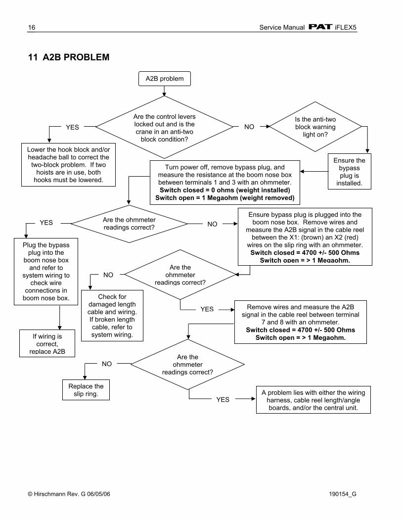
11 A2B PROBLEM
A2B problem
Ensure the bypass plug is
installed.
Turn power off, remove bypass plug, and measure the resistance at the boom nose box between terminals 1 and 3 with an ohmmeter. Switch closed = 0 ohms (weight installed)
Switch open = 1 Megaohm (weight removed)
Are the control levers locked out and is the crane in an anti-two
block condition?Lower the hook block and/or headache ball to correct the two-block problem. If two
hoists are in use, both hooks must be lowered.
If wiring is correct,
replace A2B
NO
Is the anti-two block warning
light on?NO
YES Remove wires and measure the A2B signal in the cable reel between terminal
7 and 8 with an ohmmeter. Switch closed = 4700 +/- 500 Ohms
Switch open = > 1 Megaohm.
YES
Are the ohmmeter readings correct?
YES
Plug the bypass plug into the
boom nose box and refer to
system wiring to check wire
connections in boom nose box.
NO
Check for damaged length cable and wiring. If broken length cable, refer to system wiring.
Are the ohmmeter
readings correct?
Are the ohmmeter
readings correct?NO
Replace the slip ring.
YES A problem lies with either the wiring
harness, cable reel length/angle boards, and/or the central unit.
Ensure bypass plug is plugged into the boom nose box. Remove wires and
measure the A2B signal in the cable reel between the X1: (brown) an X2 (red)
wires on the slip ring with an ohmmeter. Switch closed = 4700 +/- 500 Ohms
Switch open = > 1 Megaohm.
cann-bus communication
© Hirschmann Rev. G 06/05/06 190154_G
17
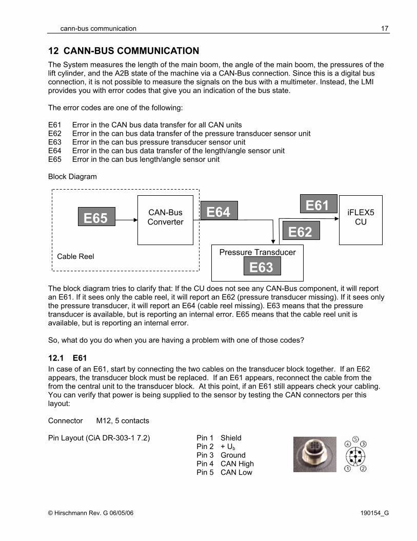
12 CANN-BUS COMMUNICATION The System measures the length of the main boom, the angle of the main boom, the pressures of the lift cylinder, and the A2B state of the machine via a CAN-Bus connection. Since this is a digital bus connection, it is not possible to measure the signals on the bus with a multimeter. Instead, the LMI provides you with error codes that give you an indication of the bus state. The error codes are one of the following: E61 Error in the CAN bus data transfer for all CAN units E62 Error in the can bus data transfer of the pressure transducer sensor unit E63 Error in the can bus pressure transducer sensor unit E64 Error in the can bus data transfer of the length/angle sensor unit E65 Error in the can bus length/angle sensor unit Block Diagram The block diagram tries to clarify that: If the CU does not see any CAN-Bus component, it will report an E61. If it sees only the cable reel, it will report an E62 (pressure transducer missing). If it sees only the pressure transducer, it will report an E64 (cable reel missing). E63 means that the pressure transducer is available, but is reporting an internal error. E65 means that the cable reel unit is available, but is reporting an internal error. So, what do you do when you are having a problem with one of those codes? 12.1 E61 In case of an E61, start by connecting the two cables on the transducer block together. If an E62 appears, the transducer block must be replaced. If an E61 appears, reconnect the cable from the from the central unit to the transducer block. At this point, if an E61 still appears check your cabling. You can verify that power is being supplied to the sensor by testing the CAN connectors per this layout: Connector M12, 5 contacts
Pin Layout (CiA DR-303-1 7.2)
Pin 1 Shield Pin 2 + Ub Pin 3 Ground Pin 4 CAN High Pin 5 CAN Low
Pressure Transducer
E63
iFLEX5
CU
Cable Reel
CAN-Bus Converter E65 E64 E61
E62
Service Manual iFLEX5
© Hirschmann Rev. G 06/05/06 190154_G
18
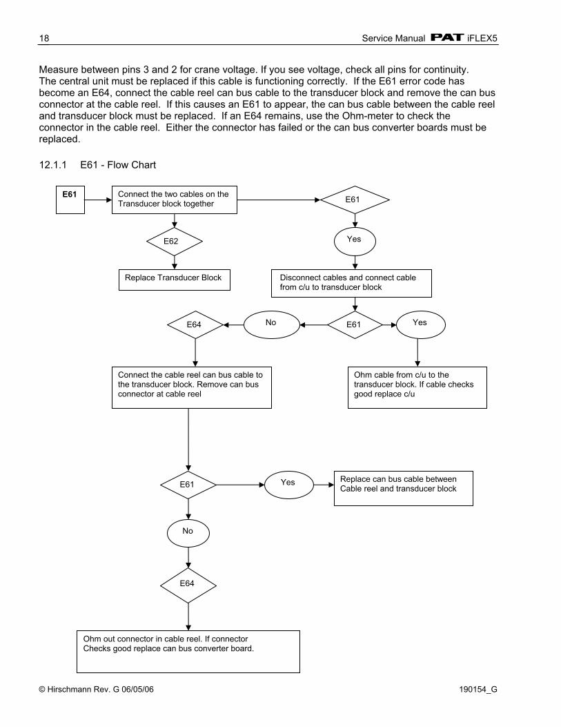
Measure between pins 3 and 2 for crane voltage. If you see voltage, check all pins for continuity. The central unit must be replaced if this cable is functioning correctly. If the E61 error code has become an E64, connect the cable reel can bus cable to the transducer block and remove the can bus connector at the cable reel. If this causes an E61 to appear, the can bus cable between the cable reel and transducer block must be replaced. If an E64 remains, use the Ohm-meter to check the connector in the cable reel. Either the connector has failed or the can bus converter boards must be replaced. 12.1.1 E61 - Flow Chart
E61 Connect the two cables on the Transducer block together E61
Yes
Disconnect cables and connect cable from c/u to transducer block
E61 Yes No
Ohm cable from c/u to the transducer block. If cable checks good replace c/u
Connect the cable reel can bus cable to the transducer block. Remove can bus connector at cable reel
E61 Yes Replace can bus cable between Cable reel and transducer block
No
Ohm out connector in cable reel. If connector Checks good replace can bus converter board.
E62
Replace Transducer Block
E64
E64

cann-bus communication
© Hirschmann Rev. G 06/05/06 190154_G
19
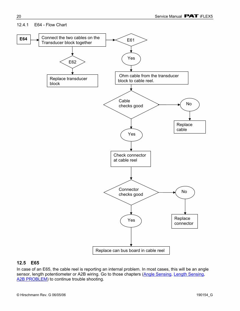
12.2 E62 In case of an E62 the CU is reporting no signal from the pressure transducer. Start by checking your cabling between CU and pressure transducer, even though it is not very likely that there is a problem with it since the same cable carries also the signals from the cable reel and those appear to be fine. You can verify that power is being supplied to the sensor by testing the CAN connectors per the above pin layout. If you are sure that the sensor is being supplied, you have to replace the pressure transducer. 12.3 E63 In case of an E63, the pressure transducer is reporting an internal problem. You cannot troubleshoot any further, but need to replace the pressure transducer. 12.4 E64 In case of an E64, the CU is reporting no signal from the cable reel unit. Start by connecting the two cables on the transducer block together. If an E62 occurs, the transducer block must be replaced. If an E61 occurs, measure the cable from the transducer block to the cable reel with an Ohm-meter. Check all pins of the CAN bus cable for continuity and cross-check for short circuits. If the continuity check fails, the cable must be replaced. If the cable appears to be fine, next check the connector at the cable reel. You can verify that power is being supplied to the sensor by testing the CAN connectors per the pin layout (see E61). Replace the connector if this check fails. If the connector checks properly, the board in the cable reel might be defective. CAN-Bus electronics in cable reel.
X1 Pin CAN 1 CAN_SHLD 2 CAN +UB 3 CAN GND 4 CAN_H 5 CAN_L
LED
X21 (angle)
X20 (length)
X14 (A2B)
X1 (CAN)
Service Manual iFLEX5
© Hirschmann Rev. G 06/05/06 190154_G
20
12.4.1 E64 - Flow Chart
12.5 E65 In case of an E65, the cable reel is reporting an internal problem. In most cases, this will be an angle sensor, length potentiometer or A2B wiring. Go to those chapters (Angle Sensing, Length Sensing, A2B PROBLEM) to continue trouble shooting.
E64 Connect the two cables on the Transducer block together E61
Yes
Ohm cable from the transducer block to cable reel.
Cable checks good No
Yes
Replace cable
Check connector at cable reel
Connector checks good No
Yes Replace connector
Replace can bus board in cable reel
E62
Replace transducer block

Troubleshooting a sensor problem using the display
© Hirschmann Rev. G 06/05/06 190154_G
21
13 TROUBLESHOOTING A SENSOR PROBLEM USING THE DISPLAY To determine whether there is a problem with a sensor, the iFLEX5 system has “sensor output screen” built in to make trouble-shooting easier. This is the right place to start if you are suspecting a problem with a sensor (and you don’t have an error code displayed). To access the sensor output screen, press the “INFO” button twice 10
.
10
to review software version information, press the “INFO” button once
.
10
To EXIT the sensor output screen, press the “INFO” button once from the software version screen to return to the operating screen
.
10
The screen will show all sensor inputs as in the example below. For each sensor, an equivalent voltage is shown in millivolts, along with the physical sensor value that that voltage refers to. Pressure sensors are shown with physical values of [bar], angle sensors and slew sensors in degrees and length sensors in feet (or meter for metric charts). At the bottom of the screen, the console software version is shown.
10
The values shown in the screen here are just examples of actual values. Refer to the table listed below for actual value ranges.
Press “INFO” To review software version information
Service Manual iFLEX5
© Hirschmann Rev. G 06/05/06 190154_G
22
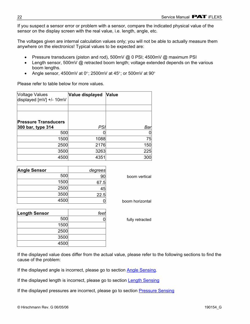
If you suspect a sensor error or problem with a sensor, compare the indicated physical value of the sensor on the display screen with the real value, i.e. length, angle, etc. The voltages given are internal calculation values only; you will not be able to actually measure them anywhere on the electronics! Typical values to be expected are:
• Pressure transducers (piston and rod), 500mV @ 0 PSI; 4500mV @ maximum PSI • Length sensor, 500mV @ retracted boom length; voltage extended depends on the various
boom lengths. • Angle sensor, 4500mV at 0°; 2500mV at 45°; or 500mV at 90°
Please refer to table below for more values. Voltage Values displayed [mV] +/- 10mV
Value displayed Value
Pressure Transducers 300 bar, type 314 PSI Bar
500 0 01500 1088 752500 2176 1503500 3263 2254500 4351 300
Angle Sensor degrees
500 90 boom vertical1500 67.52500 453500 22.54500 0 boom horizontal
Length Sensor feet
500 0 fully retracted1500 2500 3500 4500
If the displayed value does differ from the actual value, please refer to the following sections to find the cause of the problem: If the displayed angle is incorrect, please go to section Angle Sensing. If the displayed length is incorrect, please go to section Length Sensing If the displayed pressures are incorrect, please go to section Pressure Sensing

Troubleshooting a sensor problem using the display
© Hirschmann Rev. G 06/05/06 190154_G
23
SLEW POT SIGNALS:
Reference Angle Sig 1 (mA) ±0.03mA
Sig 2 (mA)±0.03mA
0° 4.00 12.00 45° 8.00 16.00 90° 12.00 20.00 135° 16.00 16.00 180° 20.00 12.00 -135° 16.00 8.00 -90° 12.00 4.00 -45° 8.00 8.00 If the displayed angle is incorrect, please go to section Slewing Sensing LED Colour Codes The bicolor LED on the central unit is used as a raw diagnostic information about the system status. It can be useful in the case that the iflex refuses terminal communication - otherwise the terminal is a much more powerful diagnostic tool. During initialization (after reset) the LED shows some of the initialization steps, so if the reset procedure hangs, it is easier to find out where. The cycle is: • RESET: red+small red (for approx 5 us) • Wait for RAM: green (for approx 200 ms) • Clear RAM: yellow (for approx 1 s) • CRC-Check System program: light yellow (2.5 s) • Init RS232/RS485 : yellow (1 s) • Start RTOS: green (0.5 s) After start of RTOS the LED toggles all 1 sec between dark/green/yellow/red. So you can detect - is the power supply ok? - is the iflex in the reset procedure, hanging somewhere or is the Operating system running? You cannot be sure if the LED shows running Operating system that all necessary tasks of the System program are running correct, too. That has to be made sure via terminal commands.
Service Manual iFLEX5
© Hirschmann Rev. G 06/05/06 190154_G
24
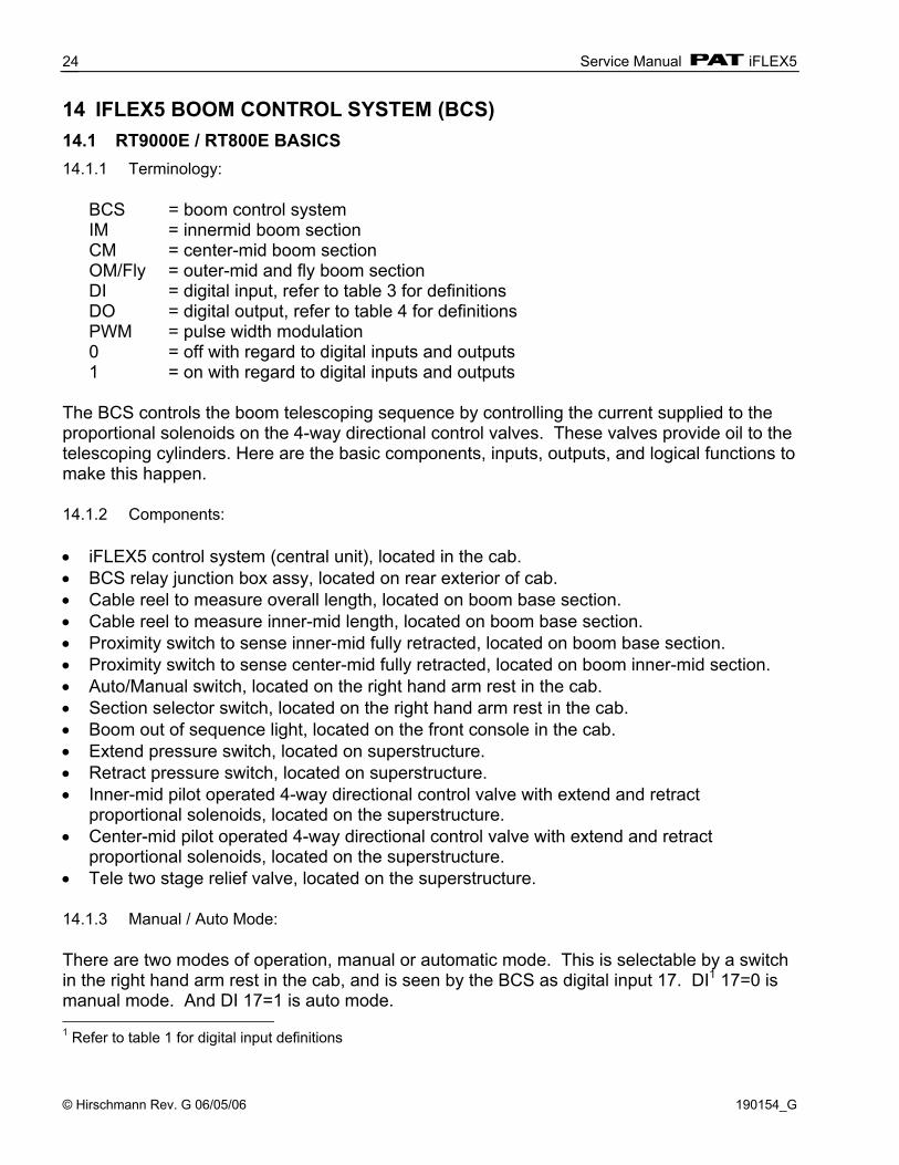
14 IFLEX5 BOOM CONTROL SYSTEM (BCS) 14.1 RT9000E / RT800E BASICS 14.1.1 Terminology: BCS = boom control system IM = innermid boom section CM = center-mid boom section OM/Fly = outer-mid and fly boom section DI = digital input, refer to table 3 for definitions DO = digital output, refer to table 4 for definitions PWM = pulse width modulation 0 = off with regard to digital inputs and outputs 1 = on with regard to digital inputs and outputs The BCS controls the boom telescoping sequence by controlling the current supplied to the proportional solenoids on the 4-way directional control valves. These valves provide oil to the telescoping cylinders. Here are the basic components, inputs, outputs, and logical functions to make this happen. 14.1.2 Components: • iFLEX5 control system (central unit), located in the cab. • BCS relay junction box assy, located on rear exterior of cab. • Cable reel to measure overall length, located on boom base section. • Cable reel to measure inner-mid length, located on boom base section. • Proximity switch to sense inner-mid fully retracted, located on boom base section. • Proximity switch to sense center-mid fully retracted, located on boom inner-mid section. • Auto/Manual switch, located on the right hand arm rest in the cab. • Section selector switch, located on the right hand arm rest in the cab. • Boom out of sequence light, located on the front console in the cab. • Extend pressure switch, located on superstructure. • Retract pressure switch, located on superstructure. • Inner-mid pilot operated 4-way directional control valve with extend and retract
proportional solenoids, located on the superstructure. • Center-mid pilot operated 4-way directional control valve with extend and retract
proportional solenoids, located on the superstructure. • Tele two stage relief valve, located on the superstructure. 14.1.3 Manual / Auto Mode: There are two modes of operation, manual or automatic mode. This is selectable by a switch in the right hand arm rest in the cab, and is seen by the BCS as digital input 17. DI1 17=0 is manual mode. And DI 17=1 is auto mode. 1 Refer to table 1 for digital input definitions
iFLEX5 Boom Control System (BCS)
© Hirschmann Rev. G 06/05/06 190154_G
25
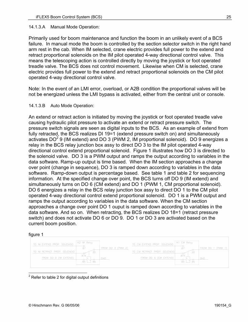
14.1.3.A Manual Mode Operation: Primarily used for boom maintenance and function the boom in an unlikely event of a BCS failure. In manual mode the boom is controlled by the section selector switch in the right hand arm rest in the cab. When IM selected, crane electric provides full power to the extend and retract proportional solenoids on the IM pilot operated 4-way directional control valve. This means the telescoping action is controlled directly by moving the joystick or foot operated treadle valve. The BCS does not control movement. Likewise when CM is selected, crane electric provides full power to the extend and retract proportional solenoids on the CM pilot operated 4-way directional control valve. Note: In the event of an LMI error, overload, or A2B condition the proportional valves will be not be energized unless the LMI bypass is activated, either from the central unit or console. 14.1.3.B Auto Mode Operation: An extend or retract action is initiated by moving the joystick or foot operated treadle valve causing hydraulic pilot pressure to activate an extend or retract pressure switch. The pressure switch signals are seen as digital inputs to the BCS. As an example of extend from fully retracted, the BCS realizes DI 19=1 (extend pressure switch on) and simultaneously activates DO2 9 (IM extend) and DO 3 (PWM 2, IM proportional solenoid). DO 9 energizes a relay in the BCS relay junction box assy to direct DO 3 to the IM pilot operated 4-way directional control extend proportional solenoid. Figure 1 illustrates how DO 3 is directed to the solenoid valve. DO 3 is a PWM output and ramps the output according to variables in the data software. Ramp-up output is time based. When the IM section approaches a change over point (change in sequence), DO 3 is ramped down according to variables in the data software. Ramp-down output is percentage based. See table 1 and table 2 for sequencing information. At the specified change over point, the BCS turns off DO 9 (IM extend) and simultaneously turns on DO 6 (CM extend) and DO 1 (PWM 1, CM proportional solenoid). DO 6 energizes a relay in the BCS relay junction box assy to direct DO 1 to the CM pilot operated 4-way directional control extend proportional solenoid. DO 1 is a PWM output and ramps the output according to variables in the data software. When the CM section approaches a change over point DO 1 ouput is ramped down according to variables in the data software. And so on. When retracting, the BCS realizes DO 18=1 (retract pressure switch) and does not activate DO 6 or DO 9. DO 1 or DO 3 are activated based on the current boom position. figure 1 2 Refer to table 2 for digital output definitions

Service Manual iFLEX5
© Hirschmann Rev. G 06/05/06 190154_G
26
14.2 TELE SEQUENCE: RT9000E: Mode “A” - not available RT800E: Mode “A” Mode “B” table1
Jib Mode (not selectable, realized by operating mode selection)
table 2 Note: Retract sequence is opposite of extend sequence. 14.3 IFLEX5 BCS DIGITAL INPUTS: table 1
Digital Input
Description *C.U. X2 Terminal
**MP
6 CM (Center-Mid) Retracted (boom proximity switch) 54 R89 7 IM (Inner-Mid) Retracted (boom proximity switch) 55 R90 8 Luffing Extension Raise (cab switch) 56 R91 9 Luffing Extension Lower (cab switch) 57 R92
10 Luffing Extension Raise (remote switch on ext.) 58 R93 11 Luffing Extension Lower (remote switch on ext.) 59 R94 16 “A” Mode (cab switch) 64 R100 17 Auto Mode (cab switch) 65 R101 18 Boom Retract (pressure switch) 66 R102 19 Boom Extend (pressure switch) 67 R103
Mode "B" Extend Sequence in Percentage Tele 1 (IM) Tele 2 (CM) Tele 3 (OM/Fly)
0 0 0 75 0 0 75 75 0
100 75 0 100 100 0 100 100 100
Jib Mode Extend Sequence in Percentage Tele 1 (IM) Tele 2 (CM) Tele 3 (OM/Fly)
100 0 0 100 100 0 100 100 100
iFLEX5 Boom Control System (BCS)
© Hirschmann Rev. G 06/05/06 190154_G
27
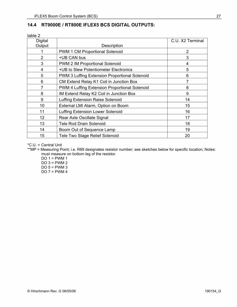
14.4 RT9000E / RT800E IFLEX5 BCS DIGITAL OUTPUTS: table 2
Digital Output Description
C.U. X2 Terminal
1 PWM 1 CM Proportional Solenoid 2 2 +UB CAN bus 3 3 PWM 2 IM Proportional Solenoid 4 4 +UB to Slew Potentiometer Electronics 5 5 PWM 3 Luffing Extension Proportional Solenoid 6 6 CM Extend Relay K1 Coil in Junction Box 7 7 PWM 4 Luffing Extension Proportional Solenoid 8 8 IM Extend Relay K2 Coil in Junction Box 9 9 Luffing Extension Raise Solenoid 14
10 External LMI Alarm, Option on Boom 15 11 Luffing Extension Lower Solenoid 16 12 Rear Axle Oscillate Signal 17 13 Tele Rod Drain Solenoid 18 14 Boom Out of Sequence Lamp 19 15 Tele Two Stage Relief Solenoid 20
*C.U. = Central Unit **MP = Measuring Point; i.e. R89 designates resistor number; see sketches below for specific location; Notes: must measure on bottom leg of the resistor. DO 1 = PWM 1 DO 3 = PWM 2 DO 5 = PWM 3 DO 7 = PWM 4

Service Manual iFLEX5
© Hirschmann Rev. G 06/05/06 190154_G
28
A convenient method to monitor digital inputs (DI) and digital outputs (DO) is utilizing the iTOOL5 or iFLASH terminal function. At the flashing command prompt press and hold “Ctrl” and “A” to enter the RTOS (an asterisk will display). Type “digshow” and press “Enter”. The result should be the screen shown below. The inputs and outputs are counted from right to left and top to bottom as illustrated below. *digshow (RTOS command to display digital inputs and outputs) T E S T D E R D I G I T A L - E I N - U N D A U S G A E N G E ======================================================================= Baugr. | Port | Modus | IN-Wert | IN-Wert | OUT-Wert | OUT-Wert | Status | :Taste | | (Hex) | (Bin) | (Hex) | (Bin) | =NoLoad -------|--------|--------|---------|----------|----------|----------|-------- Basis | 0 : 1 | NORMAL | 00 | 00000000 | 05 | 00000101 | 0000-1 Basis | 1 : 2 | NORMAL | 00 | 00000000 | 82 | 10000010 | 0011-0 Basis | 2 : 3 | NORMAL | 98 | 10011000 | 00 | | Erw. | 0 : 4 | NORMAL | 00 | 00000000 | 00 | 00000000 | 1111-1 Erw. | 1 : 5 | NORMAL | 00 | 00000000 | 00 | 00000000 | 1111-1 Erw. | 2 : 6 | NORMAL | 00 | 00000000 | 00 | 00000000 | 1111-1 -------|--------|--------|---------|----------|----------|----------|-------- Baugruppencodierung Basis : 0F = 00001111
Baugruppencodierung Erweiterung: FF = 11111111 Hubendschalter UNTB/OFFEN/OK/KURZ: 0000 X:Exit Blank:Redraw S:Slow F:Fast
Other methods to determine digital input and output states is by probing the junction box mounted on the rear of the cab, the C.U. 70-pass connector pins (X2), or specific resistors on the main board, or terminal strip in the. See table above and sketches below. Be cautious not to short the probe across connector pins. Junction Box Assy – located on rear exterior of cab
DO 16 DI 9
DI 1DI 8
DO 1

iFLEX5 Boom Control System (BCS)
© Hirschmann Rev. G 06/05/06 190154_G
29
Resistor bank to measure digital input (DI) state. Note: must measure on bottom leg of the resistor.
C.U. 70-pass connector pins (X2)
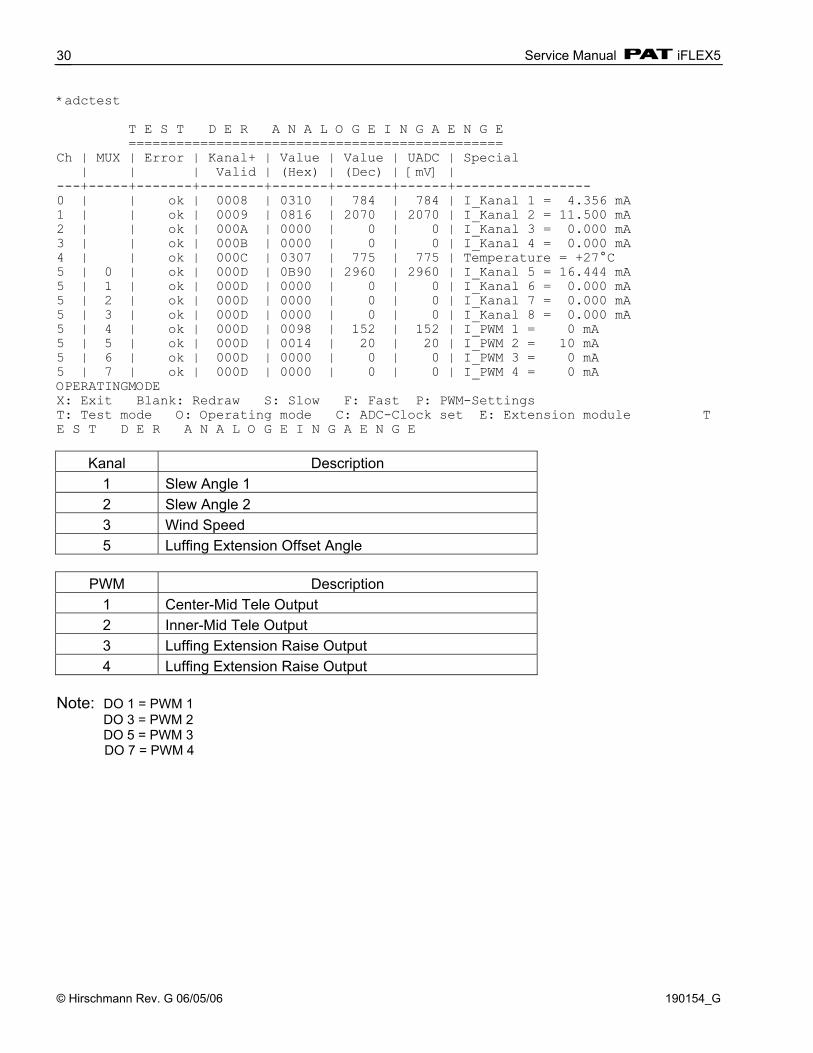
14.5 IFLEX5 BCS ANALOG INPUTS AND PWM OUTPUTS: Another useful tool to monitor analog inputs and PWM outputs is utilizing the iTOOL5 or iFLASH terminal function. At the flashing command prompt press and hold “Ctrl” and “A” to enter the RTOS (an asterisk will display). Type “adctest” and press “Enter”. The result should be the screen shown below.
Service Manual iFLEX5
© Hirschmann Rev. G 06/05/06 190154_G
30
*adctest T E S T D E R A N A L O G E I N G A E N G E =============================================== Ch | MUX | Error | Kanal+ | Value | Value | UADC | Special | | | Valid | (Hex) | (Dec) | [mV] | ---+-----+-------+--------+-------+-------+------+----------------- 0 | | ok | 0008 | 0310 | 784 | 784 | I_Kanal 1 = 4.356 mA 1 | | ok | 0009 | 0816 | 2070 | 2070 | I_Kanal 2 = 11.500 mA 2 | | ok | 000A | 0000 | 0 | 0 | I_Kanal 3 = 0.000 mA 3 | | ok | 000B | 0000 | 0 | 0 | I_Kanal 4 = 0.000 mA 4 | | ok | 000C | 0307 | 775 | 775 | Temperature = +27°C 5 | 0 | ok | 000D | 0B90 | 2960 | 2960 | I_Kanal 5 = 16.444 mA 5 | 1 | ok | 000D | 0000 | 0 | 0 | I_Kanal 6 = 0.000 mA 5 | 2 | ok | 000D | 0000 | 0 | 0 | I_Kanal 7 = 0.000 mA 5 | 3 | ok | 000D | 0000 | 0 | 0 | I_Kanal 8 = 0.000 mA 5 | 4 | ok | 000D | 0098 | 152 | 152 | I_PWM 1 = 0 mA 5 | 5 | ok | 000D | 0014 | 20 | 20 | I_PWM 2 = 10 mA 5 | 6 | ok | 000D | 0000 | 0 | 0 | I_PWM 3 = 0 mA 5 | 7 | ok | 000D | 0000 | 0 | 0 | I_PWM 4 = 0 mA OPERATINGMODE X: Exit Blank: Redraw S: Slow F: Fast P: PWM-Settings T: Test mode O: Operating mode C: ADC-Clock set E: Extension module T E S T D E R A N A L O G E I N G A E N G E
Kanal Description 1 Slew Angle 1 2 Slew Angle 2 3 Wind Speed 5 Luffing Extension Offset Angle
PWM Description
1 Center-Mid Tele Output 2 Inner-Mid Tele Output 3 Luffing Extension Raise Output 4 Luffing Extension Raise Output
Note: DO 1 = PWM 1 DO 3 = PWM 2 DO 5 = PWM 3
DO 7 = PWM 4
iFLEX5 Boom Control System (BCS)
© Hirschmann Rev. G 06/05/06 190154_G
31
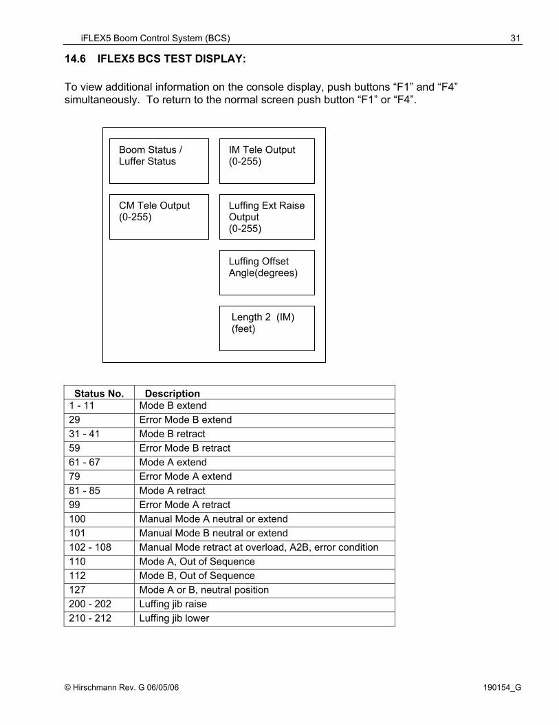
Boom Status / Luffer Status
IM Tele Output (0-255)
CM Tele Output (0-255)
Luffing Ext Raise Output (0-255)
Luffing Offset Angle(degrees)
Length 2 (IM) (feet)
14.6 IFLEX5 BCS TEST DISPLAY: To view additional information on the console display, push buttons “F1” and “F4” simultaneously. To return to the normal screen push button “F1” or “F4”.
Status No. Description 1 - 11 Mode B extend 29 Error Mode B extend 31 - 41 Mode B retract 59 Error Mode B retract 61 - 67 Mode A extend 79 Error Mode A extend 81 - 85 Mode A retract 99 Error Mode A retract 100 Manual Mode A neutral or extend 101 Manual Mode B neutral or extend 102 - 108 Manual Mode retract at overload, A2B, error condition 110 Mode A, Out of Sequence 112 Mode B, Out of Sequence 127 Mode A or B, neutral position 200 - 202 Luffing jib raise 210 - 212 Luffing jib lower
Service Manual iFLEX5
© Hirschmann Rev. G 06/05/06 190154_G
32
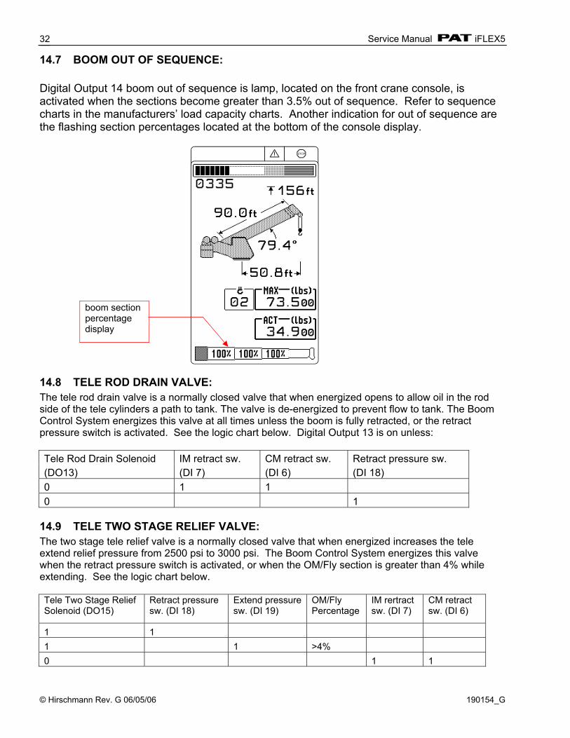
14.7 BOOM OUT OF SEQUENCE: Digital Output 14 boom out of sequence is lamp, located on the front crane console, is activated when the sections become greater than 3.5% out of sequence. Refer to sequence charts in the manufacturers’ load capacity charts. Another indication for out of sequence are the flashing section percentages located at the bottom of the console display.
14.8 TELE ROD DRAIN VALVE: The tele rod drain valve is a normally closed valve that when energized opens to allow oil in the rod side of the tele cylinders a path to tank. The valve is de-energized to prevent flow to tank. The Boom Control System energizes this valve at all times unless the boom is fully retracted, or the retract pressure switch is activated. See the logic chart below. Digital Output 13 is on unless: Tele Rod Drain Solenoid IM retract sw. CM retract sw. Retract pressure sw. (DO13) (DI 7) (DI 6) (DI 18) 0 1 1 0 1
14.9 TELE TWO STAGE RELIEF VALVE: The two stage tele relief valve is a normally closed valve that when energized increases the tele extend relief pressure from 2500 psi to 3000 psi. The Boom Control System energizes this valve when the retract pressure switch is activated, or when the OM/Fly section is greater than 4% while extending. See the logic chart below. Tele Two Stage Relief Solenoid (DO15)
Retract pressure sw. (DI 18)
Extend pressure sw. (DI 19)
OM/Fly Percentage
IM rertract sw. (DI 7)
CM retract sw. (DI 6)
1 1 1 1 >4% 0 1 1
boom section percentage display
iFLEX5 Boom Control System (BCS)
© Hirschmann Rev. G 06/05/06 190154_G
33
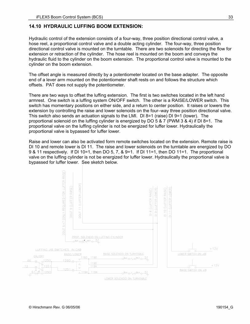
14.10 HYDRAULIC LUFFING BOOM EXTENSION: Hydraulic control of the extension consists of a four-way, three position directional control valve, a hose reel, a proportional control valve and a double acting cylinder. The four-way, three position directional control valve is mounted on the turntable. There are two solenoids for directing the flow for extension or retraction of the cylinder. The hose reel is mounted on the boom and conveys the hydraulic fluid to the cylinder on the boom extension. The proportional control valve is mounted to the cylinder on the boom extension. The offset angle is measured directly by a potentiometer located on the base adapter. The opposite end of a lever arm mounted on the potentiometer shaft rests on and follows the structure which offsets. PAT does not supply the potentiometer. There are two ways to offset the luffing extension. The first is two switches located in the left hand armrest. One switch is a luffing system ON/OFF switch. The other is a RAISE/LOWER switch. This switch has momentary positions on either side, and a return to center position. It raises or lowers the extension by controlling the raise and lower solenoids on the four–way three position directional valve. This switch also sends an actuation signals to the LMI. DI 8=1 (raise) DI 9=1 (lower). The proportional solenoid on the luffing cylinder is energized by DO 5 & 7 (PWM 3 & 4) if DI 8=1. The proportional valve on the luffing cylinder is not be energized for luffer lower. Hydraulically the proportional valve is bypassed for luffer lower. Raise and lower can also be activated form remote switches located on the extension. Remote raise is DI 10 and remote lower is DI 11. The raise and lower solenoids on the turntable are energized by DO 9 & 11 respectively. If DI 10=1, then DO 5, 7, & 9=1. If DI 11=1, then DO 11=1. The proportional valve on the luffing cylinder is not be energized for luffer lower. Hydraulically the proportional valve is bypassed for luffer lower. See sketch below.
Service Manual iFLEX5
© Hirschmann Rev. G 06/05/06 190154_G
34
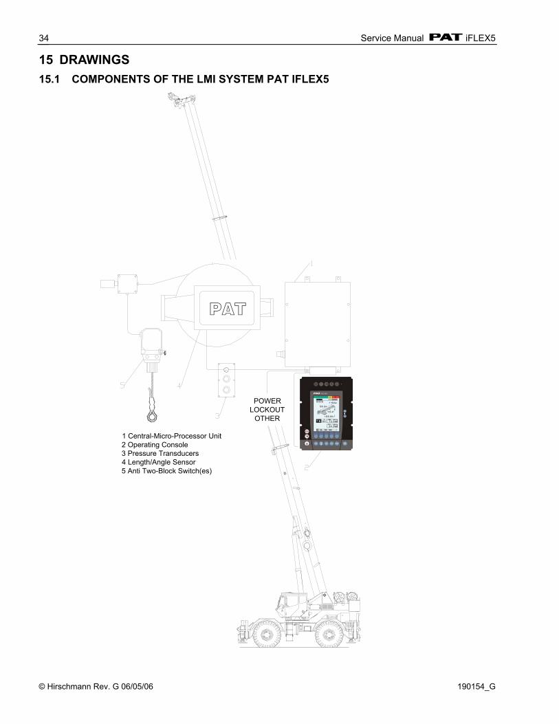
15 DRAWINGS 15.1 COMPONENTS OF THE LMI SYSTEM PAT IFLEX5
1 Central-Micro-Processor Unit2 Operating Console3 Pressure Transducers4 Length/Angle Sensor5 Anti Two-Block Switch(es)
POWERLOCKOUT
OTHER
PAT

Drawings
© Hirschmann Rev. G 06/05/06 190154_G
35
15.2 BLOCK DIAGRAM Hirschmann Electronics, Inc. reserves proprietary rights to this drawing and to the data shown there on. The drawing and data are confidential and are not to be used or reproduced without the written consent of Hirschmann. This drawing is subject to technical modification without prior notice.
CAN-BUS
RS 485 Serial
Interface
Current 4..20mA
CAN-connector
iflex5 Central Unit
Dual Pressure
Graphic Console
Length/Angle Sensor A2B Switch
Slew Sensor
70 pin Connector
Crane Power
CAN-connector
CAN-connector
Lockout
Service Manual iFLEX5
© Hirschmann Rev. G 06/05/06 190154_G
36
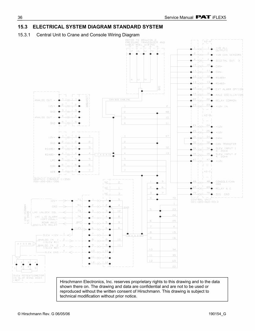
15.3 ELECTRICAL SYSTEM DIAGRAM STANDARD SYSTEM 15.3.1 Central Unit to Crane and Console Wiring Diagram
Hirschmann Electronics, Inc. reserves proprietary rights to this drawing and to the data shown there on. The drawing and data are confidential and are not to be used or reproduced without the written consent of Hirschmann. This drawing is subject to technical modification without prior notice.

Drawings
© Hirschmann Rev. G 06/05/06 190154_G
37
15.3.2 Cable Reel (length/angle sensor) Wiring Diagram
Hirschmann Electronics, Inc. reserves proprietary rights to this drawing and to the data shown there on. The drawing and data are confidential and are not to be used or reproduced without the written consent of Hirschmann. This drawing is subject to technical modification without prior notice.
Service Manual iFLEX5
© Hirschmann Rev. G 06/05/06 190154_G
38
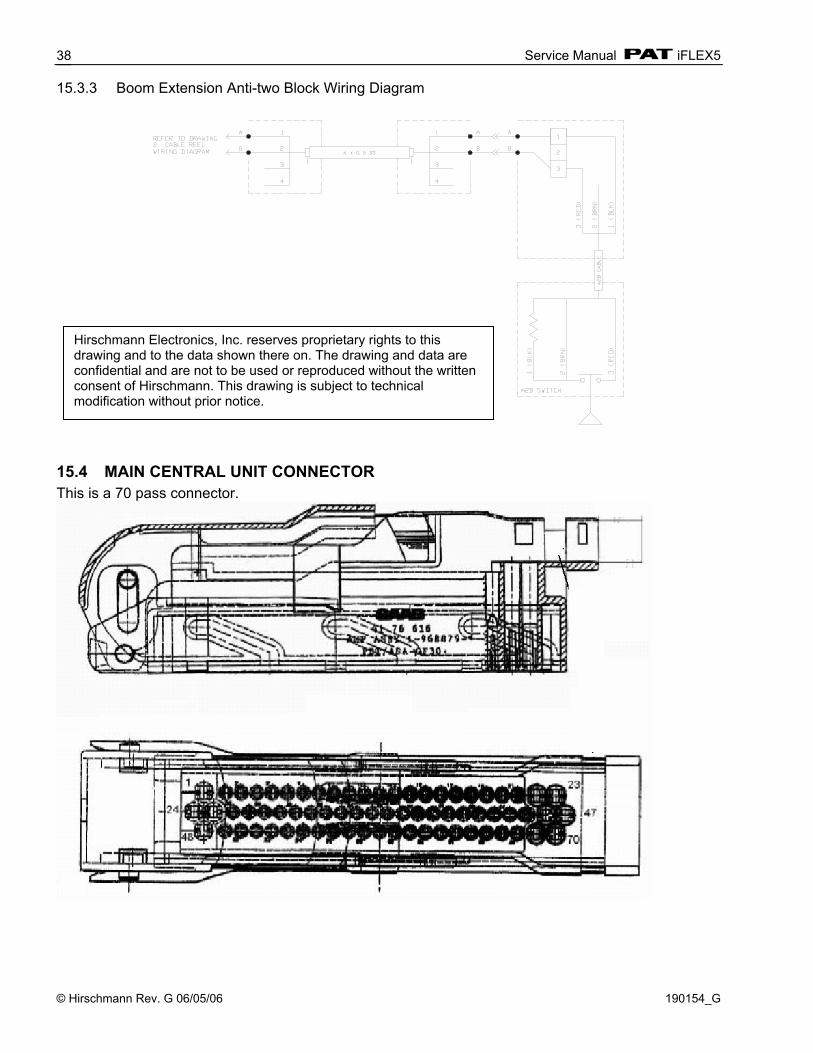
15.3.3 Boom Extension Anti-two Block Wiring Diagram
15.4 MAIN CENTRAL UNIT CONNECTOR This is a 70 pass connector.
Hirschmann Electronics, Inc. reserves proprietary rights to this drawing and to the data shown there on. The drawing and data are confidential and are not to be used or reproduced without the written consent of Hirschmann. This drawing is subject to technical modification without prior notice.
Drawings
© Hirschmann Rev. G 06/05/06 190154_G
39
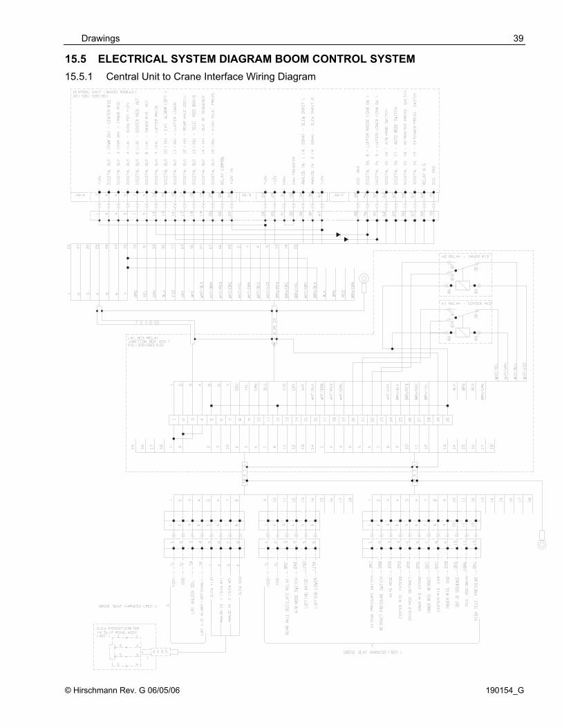
15.5 ELECTRICAL SYSTEM DIAGRAM BOOM CONTROL SYSTEM 15.5.1 Central Unit to Crane Interface Wiring Diagram
Service Manual iFLEX5
© Hirschmann Rev. G 06/05/06 190154_G
40
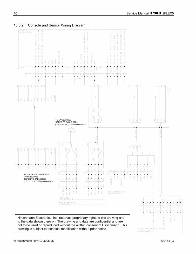
15.5.2 Console and Sensor Wiring Diagram
BOOM BASE CONNECTIONTO LG152/0056REFER TO CABLE REEL (LG152/0056) WIRING DIAGRAM
TO LWG520/0002REFER TO CABLE REEL (LWG520/0002) WIRING DIAGRAM
Hirschmann Electronics, Inc. reserves proprietary rights to this drawing and to the data shown there on. The drawing and data are confidential and are not to be used or reproduced without the written consent of Hirschmann. This drawing is subject to technical modification without prior notice.

Drawings
© Hirschmann Rev. G 06/05/06 190154_G
41
Cable Reel (LG152/0056) Wiring Diagram TO BOOM BASE CONNECTORREFER TO CONSOLE AND SENSOR WIRING DIAGRAM
TO LWG520/0002REFER TO CABLE REEL LWG520/0002 WIRING DIAGRAM
Hirschmann Electronics, Inc. reserves proprietary rights to this drawing and to the data shown there on. The drawing and data are confidential and are not to be used or reproduced without the written consent of Hirschmann. This drawing is subject to technical modification without prior notice.
Service Manual iFLEX5
© Hirschmann Rev. G 06/05/06 190154_G
42
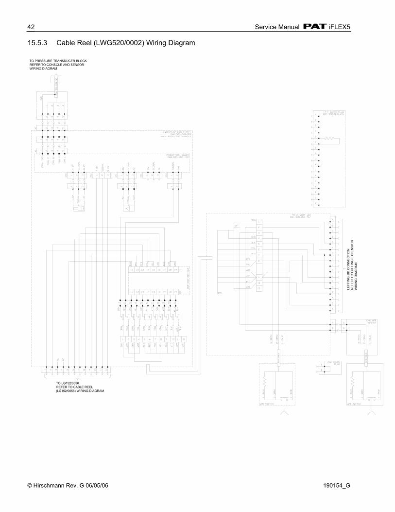
15.5.3 Cable Reel (LWG520/0002) Wiring Diagram
LUFF
ING
JIB
CO
NN
EC
TIO
NR
EFE
R T
O L
UFF
ING
EX
TEN
SIO
N
WIR
ING
DIA
GR
AM
TO LG152/0056REFER TO CABLE REEL (LG152/0056) WIRING DIAGRAM
TO PRESSURE TRANSDUCER BLOCKREFER TO CONSOLE AND SENSOR WIRING DIAGRAM

Drawings
© Hirschmann Rev. G 06/05/06 190154_G
43
15.5.4 Luffer Extension Wiring Diagram
BOOM TIP CONNECTIONTO LWG520/0002REFER TO CABLE REEL (LWG520/0002) WIRING DIAGRAM

Service Manual iFLEX5
© Hirschmann Rev. G 06/05/06 190154_G
44
16 SPARE PART LISTINGS 16.1 CENTRAL UNIT, IFLEX5 PART NO. 021-020-060-003 NO. PART NO. QTY DESCRIPTION 1 024-000-100-041 1 CENTRAL UNIT ACCY, GROUNDING KIT 2 022-022-300-031 1 BATTERY, LITHIUM 3V 3 024-350-100-661 1 KEY SWITCH 4* 031-300-110-151 1 CENTRAL UNIT COVER iFLEX 5* 024-350-100-135 1 SCREW SET 6* 031-300-101-131 1 SPARE KEY 7 024-350-110-066 42” GASKET * ITEM NOT SHOWN
1 2
3
7

Spare Part Listings
© Hirschmann Rev. G 06/05/06 190154_G
45
16.2 GRAPHIC CONSOLE ASSY, VERTICAL PART NO. 050-350-061-356 NO. PART NO. QTY DESCRIPTION 1 050-350-100-001 1 SPARE KEY, GRAPHIC CONSOLE 2 050-150-100-065 1 KEYSWITCH, WITH CABLE 3 031-300-110-149 1 FRONTFACE WITH DISPLAY, COMPUTER BOARDS, AND
LED BOARDS 4 050-150-300-068 1 CONNECTION BOARD WITH BUZZER 5 031-300-050-223 1 FUSE, 2 AMP AUTO 6 050-150-290-061 1 CABLE, 4 POL COMPUTER BRD X1 TO CONN BRD X6,X11 7 050-150-290-063 1 CABLE, 10 POL COMPUTER BRD X2 TO CONN BRD X7 8 050-150-290-064 1 CABLE, 6 POL COMPUTER BRD X10 TO CONN BRD X23 9 050-150-300-072 1 5 LED BOARD, LMI/A2B ALARM LITE 10 050-150-300-073 1 8 LED BOARD, LED’S BY SELECTION BUTTONS
Hirschmann reserves proprietary rights to this drawing and to the data shown there on. The drawing and data are confidential and are not to be used or reproduced without the written consent of Hirschmann. This drawing is subject to technical modification without prior notice.
1,2
3
5
4
2
3
6
7
8
9
10

Service Manual iFLEX5
© Hirschmann Rev. G 06/05/06 190154_G
46
16.3 GRAPHIC CONSOLE ASSY, PART NO. 050-350-061-376
ITEM PART NO. QTY DESCRIPTION
1 factory serviceable only 1 Front face, 1376 2 factory serviceable only 1 Board, console main 3 factory serviceable only 1 Display, LCD 320 x 240 4 050-150-300-086 1 Board, console connection with horn 5 050-150-300-073 1 Board, 6 x LED 6 050-150-300-092 1 Board, 5 x LED 7 092-000-060-391 1 Cable, M12 5p female x 5p JST female x 10cm 8 050-150-290-063 1 Cable, 10p 9 050-150-290-064 1 Cable, 6p
10 050-150-290-061 1 Cable, 4p 11 031-300-050-223 2 Fuse, 2A
Hirschmann Electronics, Inc. reserves proprietary rights to this document and to the data shown there on. This document and data are confidential and are not to be used or reproduced without the written consent of Hirschmann Electronics, Inc. This document is subject to technical modification without prior notice.
11
6
10
111
23
47
98
5
Spare Part Listings
© Hirschmann Rev. G 06/05/06 190154_G
47
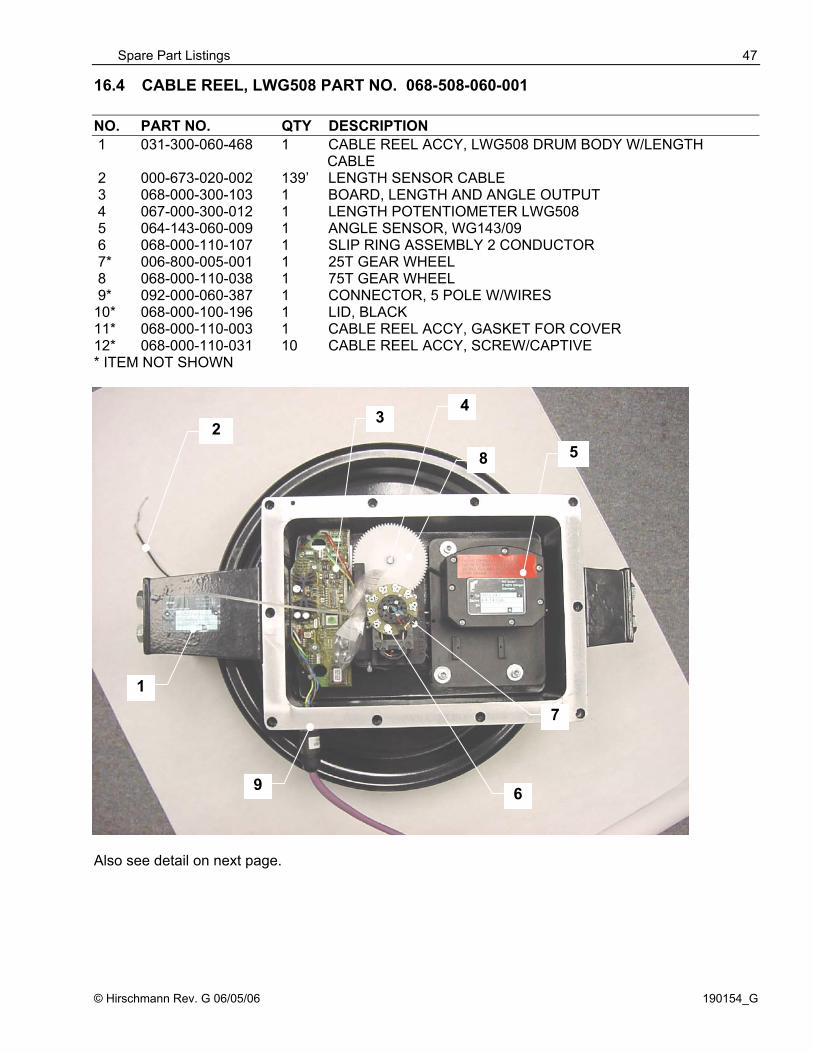
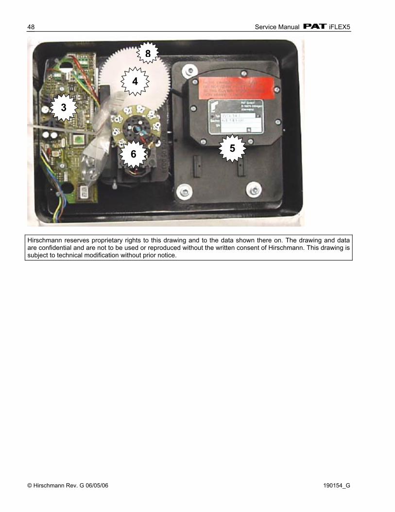
16.4 CABLE REEL, LWG508 PART NO. 068-508-060-001 NO. PART NO. QTY DESCRIPTION 1 031-300-060-468 1 CABLE REEL ACCY, LWG508 DRUM BODY W/LENGTH CABLE 2 000-673-020-002 139’ LENGTH SENSOR CABLE 3 068-000-300-103 1 BOARD, LENGTH AND ANGLE OUTPUT 4 067-000-300-012 1 LENGTH POTENTIOMETER LWG508 5 064-143-060-009 1 ANGLE SENSOR, WG143/09 6 068-000-110-107 1 SLIP RING ASSEMBLY 2 CONDUCTOR 7* 006-800-005-001 1 25T GEAR WHEEL 8 068-000-110-038 1 75T GEAR WHEEL 9* 092-000-060-387 1 CONNECTOR, 5 POLE W/WIRES 10* 068-000-100-196 1 LID, BLACK 11* 068-000-110-003 1 CABLE REEL ACCY, GASKET FOR COVER 12* 068-000-110-031 10 CABLE REEL ACCY, SCREW/CAPTIVE * ITEM NOT SHOWN
Also see detail on next page.
4
7
32
5 8
6
1
9
Service Manual iFLEX5
© Hirschmann Rev. G 06/05/06 190154_G
48
Hirschmann reserves proprietary rights to this drawing and to the data shown there on. The drawing and data are confidential and are not to be used or reproduced without the written consent of Hirschmann. This drawing is subject to technical modification without prior notice.
3
4
5 6
8
Spare Part Listings
© Hirschmann Rev. G 06/05/06 190154_G
49
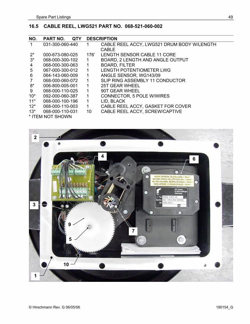
16.5 CABLE REEL, LWG521 PART NO. 068-521-060-002 NO. PART NO. QTY DESCRIPTION 1 031-300-060-440 1 CABLE REEL ACCY, LWG521 DRUM BODY W/LENGTH CABLE 2* 000-673-080-025 176’ LENGTH SENSOR CABLE 11 CORE 3* 068-000-300-102 1 BOARD, 2 LENGTH AND ANGLE OUTPUT 4 068-000-300-063 1 BOARD, FILTER 5 067-000-300-012 1 LENGTH POTENTIOMETER LWG 6 064-143-060-009 1 ANGLE SENSOR, WG143/09 7 068-000-060-072 1 SLIP RING ASSEMBLY 11 CONDUCTOR 8* 006-800-005-001 1 25T GEAR WHEEL 9 068-000-110-025 1 90T GEAR WHEEL 10* 092-000-060-387 1 CONNECTOR, 5 POLE W/WIRES 11* 068-000-100-196 1 LID, BLACK 12* 068-000-110-003 1 CABLE REEL ACCY, GASKET FOR COVER 13* 068-000-110-031 10 CABLE REEL ACCY, SCREW/CAPTIVE * ITEM NOT SHOWN
4
2
6
7
1
5
10
9
3
Service Manual iFLEX5
© Hirschmann Rev. G 06/05/06 190154_G
50
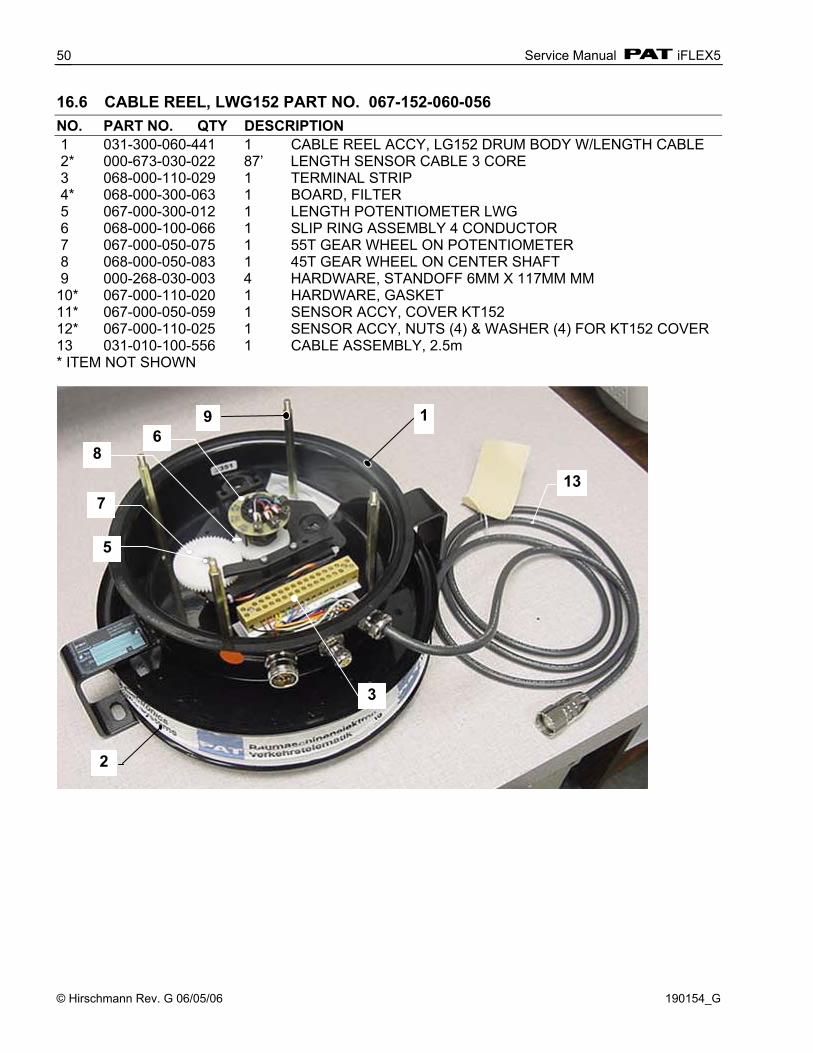
16.6 CABLE REEL, LWG152 PART NO. 067-152-060-056 NO. PART NO. QTY DESCRIPTION 1 031-300-060-441 1 CABLE REEL ACCY, LG152 DRUM BODY W/LENGTH CABLE 2* 000-673-030-022 87’ LENGTH SENSOR CABLE 3 CORE 3 068-000-110-029 1 TERMINAL STRIP 4* 068-000-300-063 1 BOARD, FILTER 5 067-000-300-012 1 LENGTH POTENTIOMETER LWG 6 068-000-100-066 1 SLIP RING ASSEMBLY 4 CONDUCTOR 7 067-000-050-075 1 55T GEAR WHEEL ON POTENTIOMETER 8 068-000-050-083 1 45T GEAR WHEEL ON CENTER SHAFT 9 000-268-030-003 4 HARDWARE, STANDOFF 6MM X 117MM MM 10* 067-000-110-020 1 HARDWARE, GASKET 11* 067-000-050-059 1 SENSOR ACCY, COVER KT152 12* 067-000-110-025 1 SENSOR ACCY, NUTS (4) & WASHER (4) FOR KT152 COVER 13 031-010-100-556 1 CABLE ASSEMBLY, 2.5m * ITEM NOT SHOWN
7 13
3
2
1
5
9 6
8

Spare Part Listings
© Hirschmann Rev. G 06/05/06 190154_G
51
16.7 PRESSURE TRANSDUCER BLOCK, DAV314/0014 PART NO. 044-314-060-014
16.8 CABLE ASSEMBLY 11M, PART NO. 031-010-101-007
16.9 WIRING HARNESS STANDARD, PART NO. 031-010-100-549
Service Manual iFLEX5
© Hirschmann Rev. G 06/05/06 190154_G
52
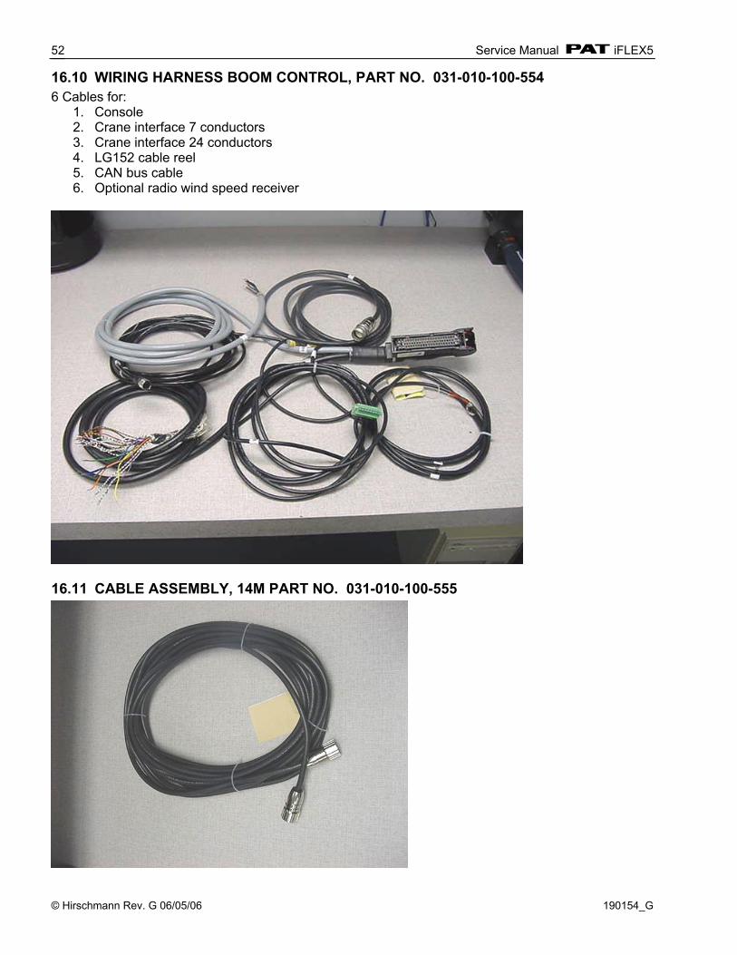
16.10 WIRING HARNESS BOOM CONTROL, PART NO. 031-010-100-554 6 Cables for:
1. Console 2. Crane interface 7 conductors 3. Crane interface 24 conductors 4. LG152 cable reel 5. CAN bus cable 6. Optional radio wind speed receiver
16.11 CABLE ASSEMBLY, 14M PART NO. 031-010-100-555

Spare Part Listings
© Hirschmann Rev. G 06/05/06 190154_G
53
16.12 TRS05 REPEATER, RADIO WINDSPEED KIT 031-300-104-087
031-300-060-596 TRS 05 REPEATER 031-300-050-688 ANTENNA, 918 MHz RCL 90°
031-300-060-601 CABLE ASSY, 15' 2 COND SS 20AWG W/12 SKT DEUTSCH

Service Manual iFLEX5
© Hirschmann Rev. G 06/05/06 190154_G
54
17 SERVICE SCREEN FOR SENSOR CALIBRATION 17.1 ACTIVATING THE SERVICE SCREEN FOR SENSOR CALIBRATION To activate the service screen and sensor calibration function, press the INFO key on the console to activate the INFO Function. Now press the CTRL key.
10
.
11
At this point, a five digit Authorization Number must be entered. Only authorized personnel may adjust the zero-point settings. Use the “>” key to switch between digits; use the “+” and “-“ keys to increase and decrease each digit. Use the enter key to confirm entry.
Now, having successfully entered a valid password, the piston-side zero-point setting function is activated. The ESC key will allow you to leave the sensor calibration function. The return key toggles between the piston-side, the rod-side zero setting, and length, and angle calibration. To adjust piston pressure now, see next section 6.2 of this manual. The return key toggles between the piston-side, the rod-side zero setting, slew angle, length, and boom angle calibration. When the sensor calibration is finished, pressing the ESC or INFO key returns the console display to normal.

Service Screen For Sensor Calibration
© Hirschmann Rev. G 06/05/06 190154_G
55
17.2 ZERO-SETTING THE TRANSDUCER INPUTS NOTE: The only thing adjustable for the pressure transducers is the zero point, which is the voltage the transducer outputs when there is no (zero) pressure sensed. CAUTION: Ensure there is no pressure in the hydraulic line when disconnecting the hoses from pressure transducers. The display shows which transducer (piston-side, rod-side or force) is being zeroed and a horizontal dial marks the present pressure (or force) difference in %. NOTE: there are 2 screens piston and rod transducers. By pressing the + key, the input pressure (or force) is adjusted upwards, and by pressing the minus (-) key, the input value is adjusted downwards. When the plus (+) and minus (-) keys are pressed simultaneously, the zero setting occurs automatically. Manual adjustments may be preformed using + or -.
17.3 ZERO-SETTING THE SLEWING INPUTS Now, having successfully entered a valid password, the piston-side zero-point setting function is activated. Press enter through the piston and rod zero adjustment screens to the slew zero-point adjustment function is activated. An indicator line shows the current position of the slew pot signal. Note: the indicator line must be shown in the display scale from -10° to +10° for this zeroing procedure. By pressing the two center keys simultaneously, the zero setting occurs automatically. Note: The indicator line will move to zero on the bar graph.
When the operator is finished, pressing the EXC or INFO key returns the console display to normal.
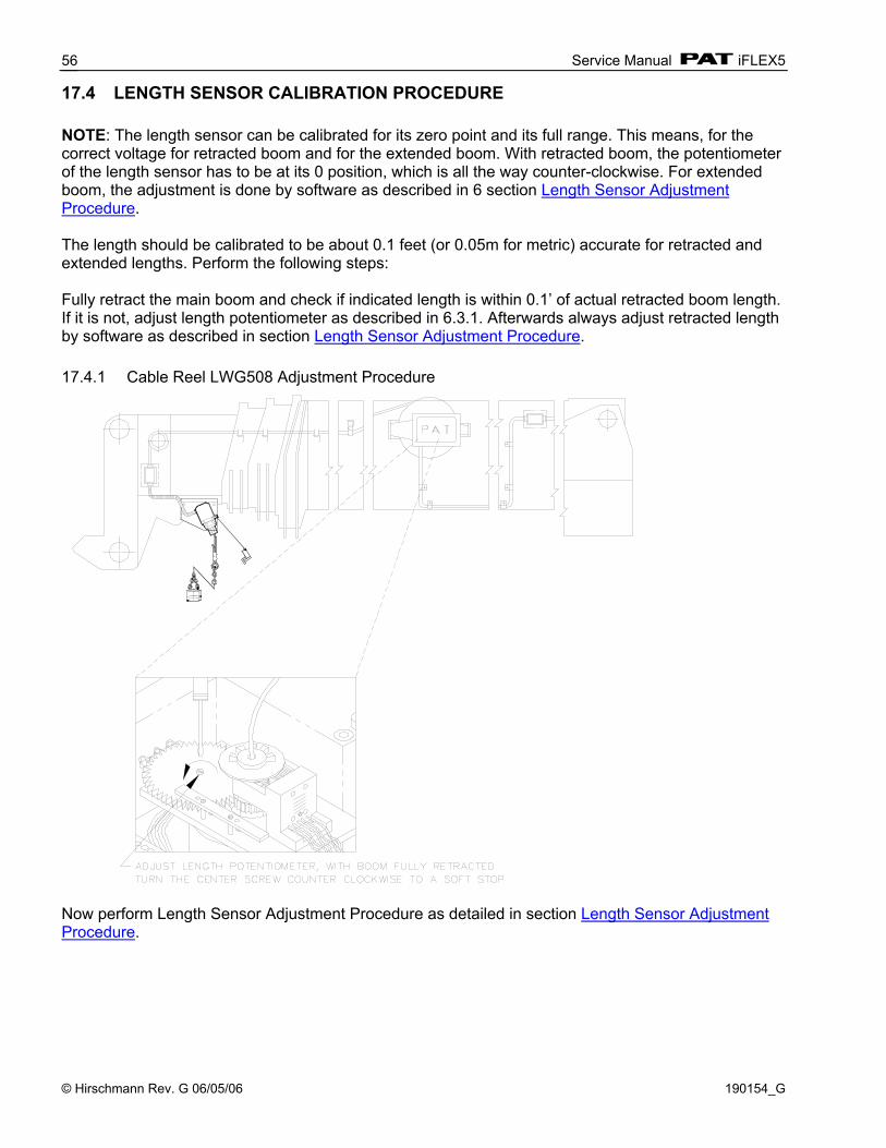
Service Manual iFLEX5
© Hirschmann Rev. G 06/05/06 190154_G
56
17.4 LENGTH SENSOR CALIBRATION PROCEDURE NOTE: The length sensor can be calibrated for its zero point and its full range. This means, for the correct voltage for retracted boom and for the extended boom. With retracted boom, the potentiometer of the length sensor has to be at its 0 position, which is all the way counter-clockwise. For extended boom, the adjustment is done by software as described in 6 section Length Sensor Adjustment Procedure. The length should be calibrated to be about 0.1 feet (or 0.05m for metric) accurate for retracted and extended lengths. Perform the following steps: Fully retract the main boom and check if indicated length is within 0.1’ of actual retracted boom length. If it is not, adjust length potentiometer as described in 6.3.1. Afterwards always adjust retracted length by software as described in section Length Sensor Adjustment Procedure. 17.4.1 Cable Reel LWG508 Adjustment Procedure
Now perform Length Sensor Adjustment Procedure as detailed in section Length Sensor Adjustment Procedure.
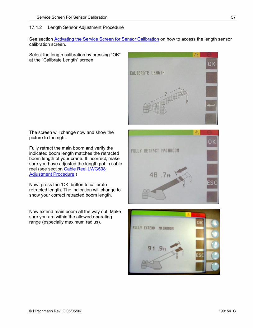
Service Screen For Sensor Calibration
© Hirschmann Rev. G 06/05/06 190154_G
57
17.4.2 Length Sensor Adjustment Procedure See section Activating the Service Screen for Sensor Calibration on how to access the length sensor calibration screen. Select the length calibration by pressing “OK” at the “Calibrate Length” screen.
The screen will change now and show the picture to the right. Fully retract the main boom and verify the indicated boom length matches the retracted boom length of your crane. If incorrect, make sure you have adjusted the length pot in cable reel (see section Cable Reel LWG508 Adjustment Procedure.) Now, press the ‘OK’ button to calibrate retracted length. The indication will change to show your correct retracted boom length.
Now extend main boom all the way out. Make sure you are within the allowed operating range (especially maximum radius).

Service Manual iFLEX5
© Hirschmann Rev. G 06/05/06 190154_G
58
17.4.3 Cable Reel Length Cable Replacement Procedure Replace length cable using the following procedure: Refer to system electrical wiring diagram and cable reel - parts list
1. Cut old cable at cable drum. 2. Disconnect damaged length cable from junction box at the boom nose. 3. Open cable reel cover and disconnect bus connector. 4. Remove cable reel from mounting brackets. 5. Remove damaged length cable, which is mounted to the slip rings in the cable reel, from slip ring
terminal. 6. On the backside of the cable reel, open the strain relief attached to the axle in the center of the
drum. Pull existing length cable out of the cable reel. 7. Pull new length cable through the hole, pipe and strain relief and push it through the axle of the
reeling drum. Tighten new strain relief to ensure sealing. 8. Reconnect the length cable to the slip ring. 9. Remount cable reel to the boom. 10. Turn reeling drum clockwise to spool the new cable neatly onto the drum. 11. Set pre-load on cable reel by turning the drum counter-clockwise 5 to 8 turns. 12. Run the new length cable through the cable guides and wrap the length cable around the boom
tip anchor pin (4 or 5 wraps) and secure with tie wraps. Leave enough length cable to connect into the boom tip junction box.
13. Connect the length cable into the boom tip junction box. 14. Reset length potentiometer in length angle transducer (screw is located in center of white gear);
with boom fully retracted, turn potentiometer carefully counter-clockwise until it stops. Recheck length and angle display. Refer to section Cable Reel LWG508 Adjustment Procedure.
15. Connect bus connector 16. Follow Length Sensor Adjustment Procedure.
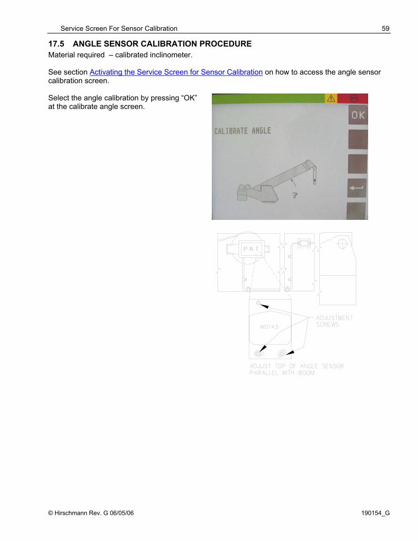
Service Screen For Sensor Calibration
© Hirschmann Rev. G 06/05/06 190154_G
59
17.5 ANGLE SENSOR CALIBRATION PROCEDURE Material required – calibrated inclinometer. See section Activating the Service Screen for Sensor Calibration on how to access the angle sensor calibration screen. Select the angle calibration by pressing “OK” at the calibrate angle screen.

Service Manual iFLEX5
© Hirschmann Rev. G 06/05/06 190154_G
60
Boom up to the next correction angle, 45 degrees (range is 40°- 50°). When the boom angle is within the calibration range, the screen will add the ‘CHANGE’, ‘SET’ and ‘OK’ text as shown on the left. Measure the boom angle with the inclinometer and when the boom is positioned in the calibration range, compare the measured angle to the displayed angle. If the indicated angle is within +/- 0.1 degrees of the measured angle, confirm with ‘OK’. Otherwise, select ‘SET’ to adjust the angle.
Once you push ‘SET’ , the screen is going to change to the angle adjustment screen. Use the ‘+’ and ‘-‘ buttons to adjust the indicated angle to match the measured angle. When the display shows the correct angle, press ‘OK’.
Repeat the above procedure to verify/set the angle at 60° (range 55°- 65°) and 70° (range 65°- 75°). boom angles. Press ESC to leave service screen.

Service Screen For Sensor Calibration
© Hirschmann Rev. G 06/05/06 190154_G
61
17.6 ZERO-SETTING THE SLEW POTENTIOMETER NOTE: The only thing adjustable for the slew potentiometer is the zero point, which is complete when the boom is at the 0° position over the front of the crane. Defining the crane zero position: The zero setting consists of defining zero-point offset. To define the zero-point or the slew potentiometer the super structure must be positioned so the boom is in the zero degree position over the front and the house lock pin engaged. Using graphic console for zero-setting of slew pot potentiometer: Press return until the slew adjustment screen is displayed. The display shows a scale from –10 to +10 degree, a horizontal mark shows the current position of the slew pot wiper. By pressing the “+” and “-“ keys simultaneously, the zero setting occurs automatically. Note: The indicator line will move to zero on the bar graph. When the operator is finished, pressing the ESC key returns the console display to normal.
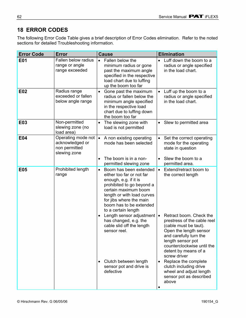
Service Manual iFLEX5
© Hirschmann Rev. G 06/05/06 190154_G
62
18 ERROR CODES The following Error Code Table gives a brief description of Error Codes elimination. Refer to the noted sections for detailed Troubleshooting information. Error Code Error Cause Elimination E01 Fallen below radius
range or angle range exceeded
• Fallen below the minimum radius or gone past the maximum angle specified in the respective load chart due to luffing up the boom too far
• Luff down the boom to a radius or angle specified in the load chart.
E02 Radius range exceeded or fallen below angle range
• Gone past the maximum radius or fallen below the minimum angle specified in the respective load chart due to luffing down the boom too far
• Luff up the boom to a radius or angle specified in the load chart.
E03 Non-permitted slewing zone (no load area)
• The slewing zone with load is not permitted
• Slew to permitted area
E04
Operating mode not acknowledged or non permitted slewing zone
• A non existing operating mode has been selected
• Set the correct operating mode for the operating state in question
• The boom is in a non-
permitted slewing zone • Slew the boom to a
permitted area. E05
Prohibited length range
• Boom has been extended either too far or not far enough, e.g. if it is prohibited to go beyond a certain maximum boom length or with load curves for jibs where the main boom has to be extended to a certain length
• Extend/retract boom to the correct length
• Length sensor adjustment has changed, e.g. the cable slid off the length sensor reel.
• Retract boom. Check the prestress of the cable reel (cable must be taut). Open the length sensor and carefully turn the length sensor pot counterclockwise until the detent by means of a screw driver
• Clutch between length sensor pot and drive is defective
• Replace the complete clutch including drive wheel and adjust length sensor pot as described above
•
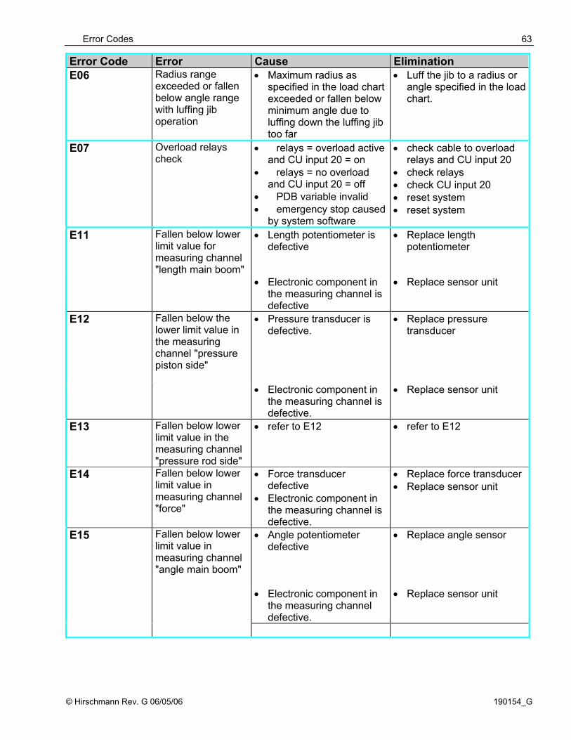
Error Codes
© Hirschmann Rev. G 06/05/06 190154_G
63
Error Code Error Cause Elimination E06 Radius range
exceeded or fallen below angle range with luffing jib operation
• Maximum radius as specified in the load chart exceeded or fallen below minimum angle due to luffing down the luffing jib too far
• Luff the jib to a radius or angle specified in the load chart.
E07 Overload relays check
• relays = overload active and CU input 20 = on
• relays = no overload and CU input 20 = off
• PDB variable invalid • emergency stop caused
by system software
• check cable to overload relays and CU input 20
• check relays • check CU input 20 • reset system • reset system
E11 Fallen below lower limit value for measuring channel "length main boom"
• Length potentiometer is defective
• Replace length potentiometer
• Electronic component in the measuring channel is defective
• Replace sensor unit
E12
Fallen below the lower limit value in the measuring channel "pressure piston side"
• Pressure transducer is defective.
• Replace pressure transducer
• Electronic component in the measuring channel is defective.
• Replace sensor unit
E13
Fallen below lower limit value in the measuring channel "pressure rod side"
• refer to E12 • refer to E12
E14 Fallen below lower limit value in measuring channel "force"
• Force transducer defective
• Electronic component in the measuring channel is defective.
• Replace force transducer • Replace sensor unit
E15 Fallen below lower limit value in measuring channel "angle main boom"
• Angle potentiometer defective
• Replace angle sensor
• Electronic component in the measuring channel defective.
• Replace sensor unit
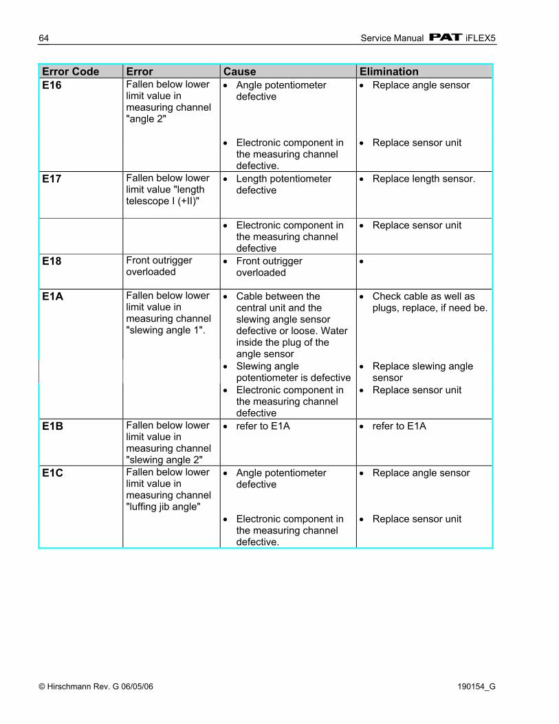
Service Manual iFLEX5
© Hirschmann Rev. G 06/05/06 190154_G
64
Error Code Error Cause Elimination E16 Fallen below lower
limit value in measuring channel "angle 2"
• Angle potentiometer defective
• Replace angle sensor
• Electronic component in the measuring channel defective.
• Replace sensor unit
E17 Fallen below lower limit value "length telescope I (+II)"
• Length potentiometer defective
• Replace length sensor.
• Electronic component in the measuring channel defective
• Replace sensor unit
E18 Front outrigger overloaded
• Front outrigger overloaded
•
E1A Fallen below lower limit value in measuring channel "slewing angle 1".
• Cable between the central unit and the slewing angle sensor defective or loose. Water inside the plug of the angle sensor
• Check cable as well as plugs, replace, if need be.
• Slewing angle potentiometer is defective
• Replace slewing angle sensor
• Electronic component in the measuring channel defective
• Replace sensor unit
E1B Fallen below lower limit value in measuring channel "slewing angle 2"
• refer to E1A
• refer to E1A
E1C Fallen below lower limit value in measuring channel "luffing jib angle"
• Angle potentiometer defective
• Replace angle sensor
• Electronic component in the measuring channel defective.
• Replace sensor unit
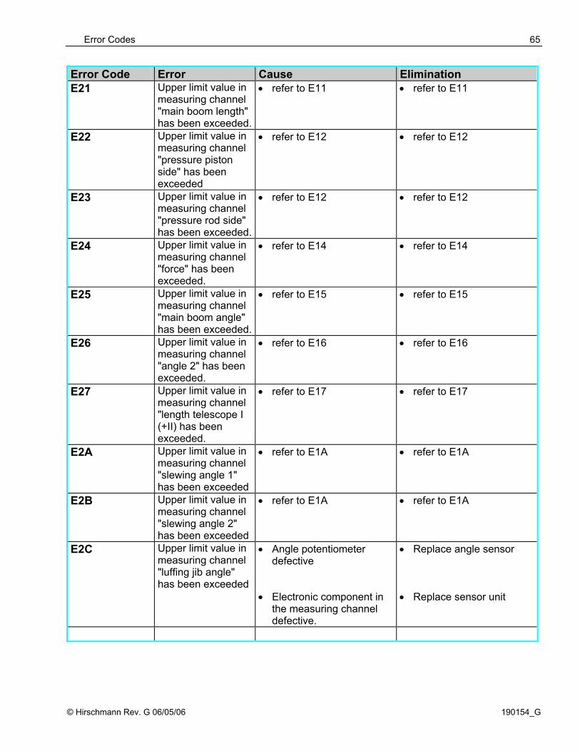
Error Codes
© Hirschmann Rev. G 06/05/06 190154_G
65
Error Code Error Cause Elimination E21
Upper limit value in measuring channel "main boom length" has been exceeded.
• refer to E11
• refer to E11
E22
Upper limit value in measuring channel "pressure piston side" has been exceeded
• refer to E12
• refer to E12
E23
Upper limit value in measuring channel "pressure rod side" has been exceeded.
• refer to E12
• refer to E12
E24 Upper limit value in measuring channel "force" has been exceeded.
• refer to E14
• refer to E14
E25
Upper limit value in measuring channel "main boom angle" has been exceeded.
• refer to E15 • refer to E15
E26 Upper limit value in measuring channel "angle 2" has been exceeded.
• refer to E16 • refer to E16
E27 Upper limit value in measuring channel "length telescope I (+II) has been exceeded.
• refer to E17 • refer to E17
E2A Upper limit value in measuring channel "slewing angle 1" has been exceeded
• refer to E1A
• refer to E1A
E2B Upper limit value in measuring channel "slewing angle 2" has been exceeded
• refer to E1A
• refer to E1A
E2C Upper limit value in measuring channel "luffing jib angle" has been exceeded
• Angle potentiometer defective
• Replace angle sensor
• Electronic component in the measuring channel defective.
• Replace sensor unit
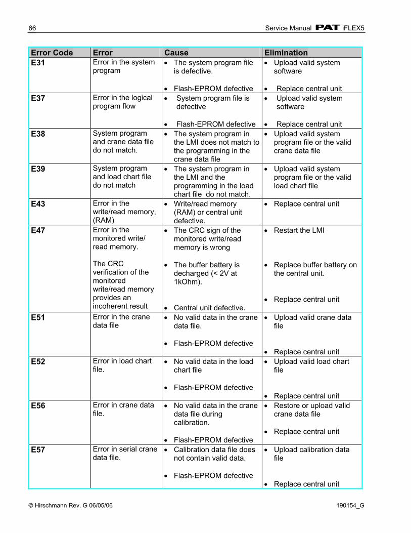
Service Manual iFLEX5
© Hirschmann Rev. G 06/05/06 190154_G
66
Error Code Error Cause Elimination E31
Error in the system program
• The system program file is defective.
• Flash-EPROM defective
• Upload valid system software
• Replace central unit
E37 Error in the logical program flow
• System program file is defective
• Flash-EPROM defective
• Upload valid system software
• Replace central unit
E38
System program and crane data file do not match.
• The system program in the LMI does not match to the programming in the crane data file
• Upload valid system program file or the valid crane data file
E39
System program and load chart file do not match
• The system program in the LMI and the programming in the load chart file do not match.
• Upload valid system program file or the valid load chart file
E43
Error in the write/read memory, (RAM)
• Write/read memory (RAM) or central unit defective.
• Replace central unit
E47 Error in the monitored write/ read memory. The CRC verification of the monitored write/read memory provides an incoherent result
• The CRC sign of the monitored write/read memory is wrong
• The buffer battery is
decharged (< 2V at 1kOhm).
• Central unit defective.
• Restart the LMI • Replace buffer battery on
the central unit. • Replace central unit
E51
Error in the crane data file
• No valid data in the crane data file.
• Flash-EPROM defective
• Upload valid crane data file
• Replace central unit
E52
Error in load chart file.
• No valid data in the load chart file
• Flash-EPROM defective
• Upload valid load chart file
• Replace central unit
E56
Error in crane data file.
• No valid data in the crane data file during calibration.
• Flash-EPROM defective
• Restore or upload valid crane data file
• Replace central unit
E57
Error in serial crane data file.
• Calibration data file does not contain valid data.
• Flash-EPROM defective
• Upload calibration data file
• Replace central unit

Error Codes
© Hirschmann Rev. G 06/05/06 190154_G
67
Error Code Error Cause Elimination E60 The number of the
selected File base and the programmed value are not identical
• No valid data in the load chart file
• Upload valid load chart file
• Base number not programmed
• Program the correct base number (1 for base 1, 2 for base 2)
• Load chart file wrongly programmed
• Check base programming in the load chart file.
E61
Error in the CAN bus data transfer for all CAN units
• CAN Bus cable between the central unit and the sensor unit defective or not connected.
• Check the connection between the central unit and the sensor units
• Can bus port in the central unit defective
• Replace the central unit
• Short circuit in a CAN Bus cable
• Replace Can Bus cable
E62
Error in the can bus data transfer of the pressure transducer sensor unit
• Cable between the central unit and the sensor unit defective.
• Check the cable to the sensor unit
• Can bus port in the central unit defective
• Replace the central unit
• Can bus port in the sensor unit is defective
• Replace the sensor unit
• Sensor unit is defective • Replace the sensor unit E63
Error in the can bus pressure transducer sensor unit
• The analog values of the sensor unit are invalid
• Replace the sensor unit
E64
Error in the can bus data transfer of the length/angle sensor unit
• See E62 • See E62
E65
Error in the can bus length/angle sensor unit
• See E63 • See E63
E66
Error in the can bus data transfer of the 2nd length/angle sensor unit
• See E62 • See E62
E67
Error in the can bus of the 2nd length /angle sensor unit
• See E63 • See E63
E68
Error in the can bus data transfer of the force sensor unit
• See E62 • See E62
E69
Error in the can bus force sensor unit
• See E63 • See E63

Service Manual iFLEX5
© Hirschmann Rev. G 06/05/06 190154_G
68
Error Code Error Cause Elimination E80 Error in the slewing
angle measurement
• The difference between the average of the slewing angle and one of the wipers of the slewing potentiometer is out of the tolerance
• Check the slewing potentiometer adjustment
• Replace slewing angle
sensor
E82
Error boom control task
• The boom control task is not running
• Restart the system • Load the boom control
task E84
Wrong rigging condition.
• The selected rigging condition is not contained in the crane data file.
• Select another rigging condition
• Check the programming
in the crane data file. E85
Error in the radius determination
• The computed radius is too small (negative deflection)
• Check the programming in the crane data file.
E89
Operating mode switchover with load.
• The operating mode on the console has been switched over with the boom loaded.
• Select operating mode without load on the boom
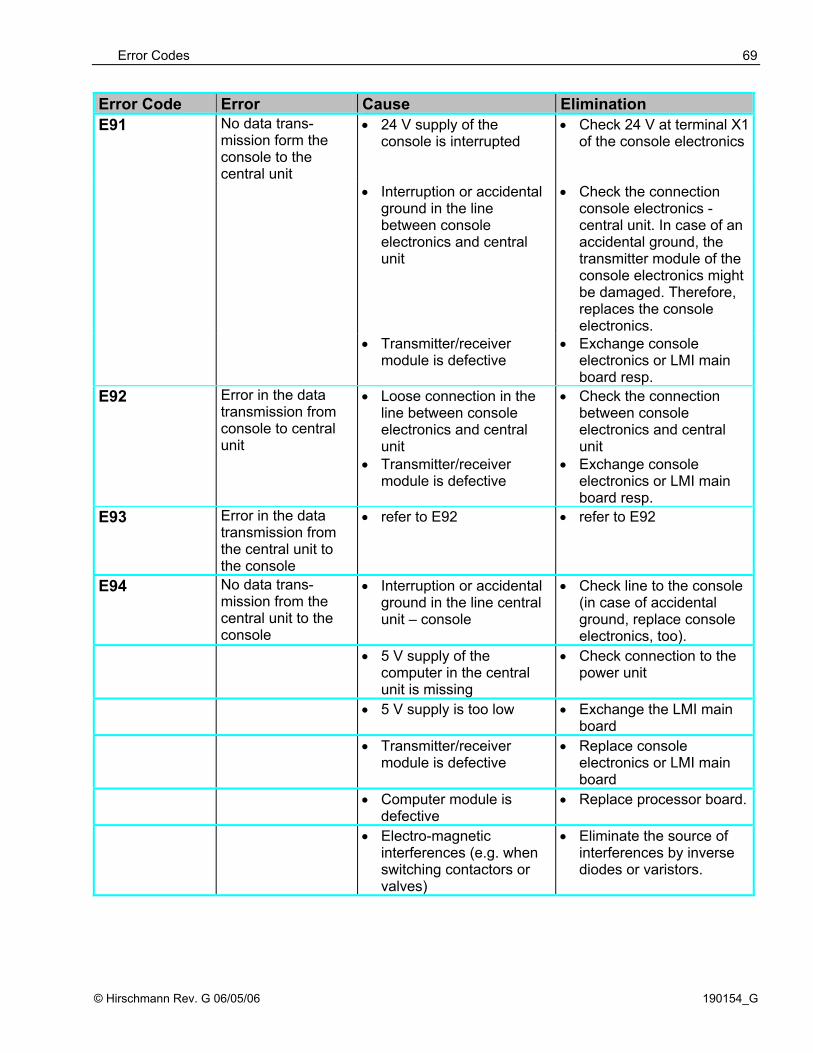
Error Codes
© Hirschmann Rev. G 06/05/06 190154_G
69
Error Code Error Cause Elimination E91 No data trans-
mission form the console to the central unit
• 24 V supply of the console is interrupted
• Check 24 V at terminal X1 of the console electronics
• Interruption or accidental ground in the line between console electronics and central unit
• Check the connection console electronics - central unit. In case of an accidental ground, the transmitter module of the console electronics might be damaged. Therefore, replaces the console electronics.
• Transmitter/receiver module is defective
• Exchange console electronics or LMI main board resp.
E92 Error in the data transmission from console to central unit
• Loose connection in the line between console electronics and central unit
• Transmitter/receiver module is defective
• Check the connection between console electronics and central unit
• Exchange console electronics or LMI main board resp.
E93 Error in the data transmission from the central unit to the console
• refer to E92 • refer to E92
E94
No data trans-mission from the central unit to the console
• Interruption or accidental ground in the line central unit – console
• Check line to the console (in case of accidental ground, replace console electronics, too).
• 5 V supply of the computer in the central unit is missing
• Check connection to the power unit
• 5 V supply is too low • Exchange the LMI main board
• Transmitter/receiver module is defective
• Replace console electronics or LMI main board
• Computer module is defective
• Replace processor board.
• Electro-magnetic interferences (e.g. when switching contactors or valves)
• Eliminate the source of interferences by inverse diodes or varistors.

Service Manual iFLEX5
© Hirschmann Rev. G 06/05/06 190154_G
70
Error Code Error Cause Elimination E95
Error in the console File
• The console File is defective.
• Replace the console File
E96
Error in the internal RAM of the console.
• The CPU of the console is defective.
• The console main board
is defective.
• Replace the CPU of the console
• Replace the console main
board. E97
Error in the external RAM of the console
• The external RAM of the console is defective.
• The console main board
is defective.
• Replace the external RAM of the console.
• Replace the console main
board. E98
LMI watchdog activated
• LMI processing time limit exceeded
• Reset system • Connect PC terminal and
watch error messages EAB Short circuit in the
A2B switch circuit • Short circuit in the A2B
switch • Short circuit in the cable
to the A2B switch
• Replace A2B switch • Replace cable to the A2B
switch EAC A2B switch circuit
disconnected • Disconnected cable in the
A2B switch • Disconnected cable to the
A2B switch
• Connect or replace cable in the A2B switch
• Connect or replace cable
to the A2B switch EAD No valid A2B switch
status • Sensor wrong function • CAN bus delay
• Replace A2B switch • Replace cable to the A2B
switch EC0 Prohibited area • Boom is about to collide
with the engine hood, switch off
• Move boom to permitted area
• Check values in the data
prom DGA 11.5. EC1 Approaching
prohibited area • Boom is about to collide
with the engine hood, prewarning
• Move boom to permitted area
• Check values in the data
prom DGA 11.5. EC2 Angle range of
luffing jib exceeded • Luffing jib is raised too far • Luff down the jib to a
angle specified in the load chart.
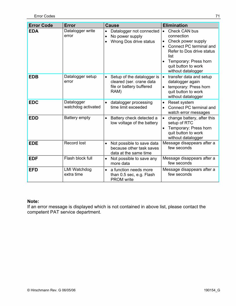
Error Codes
© Hirschmann Rev. G 06/05/06 190154_G
71
Error Code Error Cause Elimination EDA Datalogger write
error • Datalogger not connected • No power supply • Wrong Dos drive status
• Check CAN bus connection
• Check power supply • Connect PC terminal and
Refer to Dos drive status list
• Temporary: Press horn quit button to work without datalogger
EDB Datalogger setup error
• Setup of the datalogger is cleared (ser. crane data file or battery buffered RAM)
• transfer data and setup datalogger again
• temporary: Press horn quit button to work without datalogger
EDC
Datalogger watchdog activated
• datalogger processing time limit exceeded
• Reset system • Connect PC terminal and
watch error messages EDD
Battery empty • Battery check detected a low voltage of the battery
• change battery, after this setup of RTC
• Temporary: Press horn quit button to work without datalogger
EDE
Record lost • Not possible to save data because other task saves data at the same time
Message disappears after a few seconds
EDF
Flash block full • Not possible to save any more data
Message disappears after a few seconds
EFD
LMI Watchdog extra time
• a function needs more than 0.5 sec, e.g. Flash PROM write
Message disappears after a few seconds
Note: If an error message is displayed which is not contained in above list, please contact the competent PAT service department.

Service Manual iFLEX5
© Hirschmann Rev. G 06/05/06 190154_G
72
19 TROUBLESHOOTING MOISTURE The PAT iFLEX5 LMI contains electronic components in various locations, such as central unit, sensors, junction boxes etc. These internal components cannot be designed to withstand exposure to moisture over a longer period of time. For this reason, the housings of the components are water protected according to IP 65. If you find water or moisture inside any of the housings, the source for the water ingress has to be detected and corrected to ensure proper operation. There are two major possibilities for the occurrence of excessive moisture inside an enclosure: 1) Water ingress 2) Condensation This outline gives instructions for detecting the cause for excessive moisture by using simple troubleshooting methods and how to prevent the moisture ingress from happening again. 19.1 WATER INGRESS There are 6 possibilities for water to enter an enclosure: 1) Spray Cleaning 2) Missing / Loose Screws 3) Bent Lid 4) Defective Gasket 5) Loose Strain Relieves 6) Water Entry Through External Cabling It is possible to find out the source of water ingress by going through the following steps and ruling out one possibility after the other until the cause is identified: 1) Spray Cleaning
The enclosures used for the PAT LMI system are water protected to IP 65. This means protection against the environment, such as rain. However, through the use of spray cleaner at short distances, it is possible to force water through the gasket or strain relieves. For this reason, avoid spraying any components from short distances with spray cleaners. Convey this fact to any member of a maintenance crew.
2) Missing / Loose Screws
All screws have to be present and to be equally tight to ensure water protection of the enclosure. If there are screws missing, replace them. If no screw is missing, check the tightness. If any were loose, then open all screws and then re-tighten them equally.
3) Bent Lid
An enclosure will only seal correctly if the lid is not bent. To check this, loosen all screws of the lid, take the lid off the box and visually inspect it for deflection. If the lid is bent or damaged, it needs to be replaced. Try to determine what has caused the lid to be bent and eliminate the reason for that. Order a new lid through your PAT representative.
Troubleshooting Moisture
© Hirschmann Rev. G 06/05/06 190154_G
73
4) Defective Gasket
The gasket underneath the lid seals the unit. The gasket needs to be in good condition in order to seal correctly. If the gasket is torn, brittle or severely bent, it needs to be replaced. Order a new gasket through your PAT representative.
5) Loose Strain Relieves
The strain relieves allow cabling to enter the box without allowing water to enter it. The strain relieves have to be correctly tightened in order to do this. Check the tightness by taking the external cable into one hand and carefully trying to turn it. If the internal wires turn with the outer cable, the strain relief is loose. Get a new grommet (insert) through your PAT representative and replace the existing one with the new one. Tighten the strain relief correctly. Note: Whenever a strain relief is opened, i.e. to replace a cable, a new grommet needs to be used. Never re-use any grommet or the strain relief will not seal properly!
6) Water Entry Through External Cabling
Even with a tight strain relief, water may still enter the box through the inside of the cable. In this case, you have to find out why and where water enters the cable. Look for damages to the cable itself and inspect the opposite side of the cable. In example, if the cable comes from a connector that is full of water, the water will run through the inside of the cable and fill up the central unit, too.
19.2 CONDENSATION In a climate with high humidity and rapidly changing temperatures, condensation can happen inside any enclosure, usually the larger the volume of the box, the more likely. In this case, water drops build up on the inner components when humid air is trapped inside the box. With condensation, water tightness is not a problem – the box is sealed just fine, which is what prevents the trapped air from exiting the box. There are two ways to deal with condensation:
1. If the volume is very small, a desiccant bag might be able to soak up the air’s humidity. 2. If the effect is more severe, the only way to get rid of this effect is then to give the box the
ability to breath without sacrificing its water tightness. Contact your PAT representative for breathing elements to than can be added to the box and will help to reduce the effects of humid climates.