Load Line range of Moulded Case Circuit Breakers are ... 22-61 MCCB.pdfMoulded Case Circuit Breaker...
40
Load Line range of Moulded Case Circuit Breakers are designed and manufactured to world-class standards. Loadline series MCCBs provide overload and short-circuit protection for all applications. The thermal & magnetic elements, adjustable over a wide band, make these MCCBs ideal for any distribution application. Range : 25A to 1600A in 5 frame sizes in single pole, three pole and four pole with switched neutral execution. Specification : Conforms to IEC:60947-1&2 / IS:13947-1&2. Features : n n / 4-10 times I n 22
Transcript of Load Line range of Moulded Case Circuit Breakers are ... 22-61 MCCB.pdfMoulded Case Circuit Breaker...

Load Line range of Moulded Case Circui t Breakers are designed and manufactured to wor ld-class standards. Loadline series MCCBs provide overload and short-circuit protection for all applications. The thermal & magnetic elements, adjustable over a wide band, make these MCCBs ideal for any distribution application.
Range :25A to 1600A in 5 frame sizes in single pole, three pole and four pole with switched neutral execution.
Specification :Conforms to IEC:60947-1&2 / IS:13947-1&2.
Features :
n
n / 4-10 times I
n
22

Moulded Case Circuit Breaker
23

24
Moulded Case Circuit Breaker
HAVELLS
Loadline Moulded Case Circuit Breakers have precision formed moulded case and cover of high performance resin bonded thermoset material. The circuit breakers are designed to allow grouping in distribution panels or switchboards to present their operating handles and label escutcheons uniformly aligned in a single panel cut out.
The switching mechanism is Quick make-Quick break type and is tripfree, i.e. the breaker trips
position.
The contact mechanismmoving contacts made of sintered silver alloy for reliability, long life and anti-welding properties. Arcing contacts are provided in higher frames, further increasing the contact life.
The arc extinguishing device comprises of arc chutes having grid plates mounted in parallel between supports of insulating material. The arc is divided between these grid plates which helps in its
and extinguished in the arc chute. The excellent insulation between the conducting parts and better energy dissipiation after short circuit makes it possible to make the load and line connections on either side.
Construction
The tripping mechanismin each pole coupled to a single trip bar unit to avoid single phasing. The overload and magnetic setting are front adjustable on site.
Thermal Magnetic Type
The overload protection is provided by a combination of the heater element and the bimetal strip in each phase which activates the trip mechanism.
opening of the contacts limiting the prospective short circuit current.
Arc
Chute
Switching MechanismContact
Mechanism
to trip
Trip Bar
Overload
& short circuit
adjustmentTrip Bar
Instantaneous
trip release

25
Moulded Case Circuit Breaker
HAVELLS
Frame GS GN GH
n25-125* 25-125* 25-100*
Thermal relelase setting Fixed Fixed Fixed
Magnetic release setting for current rating : 25A - 50A A 500 500 500 63A - 80A A 800 800 800 100A - 125A A 1000 1000 1000
Rated short circuit making capacity
Rated ultimate short circuit breaking
Internal Accessories
External Accessories
Back Studs - - -
Standard conformity : IEC 60947-2/IS:13947-2
Type of release : Thermomagnetic
Rated frequency : 50/60 HzAmbient temp : 40o o
Operating altitude : 2000 meters
Technical Information G-Frame
* Current Ratings - 25A, 32A, 40A, 50A, 63A, 80A, 100A, 125A

26
Moulded Case Circuit Breaker
HAVELLS
Frame AAS AAN
n25-200* 25-250*
n n
Magnetic release setting for current rating :
25A - 63A 400A 400A
80A - 125A 800A 800A
160A - 250A 1600A 1600A
50A -125A AM Frame - -
160A -250A AM Frame - -
Rated ultimate short circuit breaking
Internal Accessories
External Accessories
Standard conformity : IEC 60947-2/IS:13947-2
Type of release : Thermomagnetic
Rated frequency : 50/60HzAmbient temp : 40o o
Operating altitude : 2000 meters
* Current Ratings - 25A, 32A, 40A, 50A, 63A, 80A, 100A, 125A, 160A, 200A, 250A
Technical Information AA-Frame

27
Moulded Case Circuit Breaker
HAVELLS
Technical Information F-Frame
Standard conformity : IEC 60947-2/IS:13947-2
Type of release : Thermomagnetic
Rated frequency : 50/60HzAmbient temp : 40o o
Operating altitude : 2000 meters
* Current Ratings - 25A, 32A, 40A, 50A, 63A, 80A, 100A, 125A, 160A, 200A, 250A
# Factory Fitted
Frame F N F H
25-250* 25-250*
Thermal release setting Fixed Fixed
Magnetic release setting for current rating Fixed Fixed
25A - 32A 500A 500A
40A - 80A 800A 800A
100A - 125A 1250A 1250A
160A - 250A 1600A 1600A
Rated ultimate short circuit breaking
Terminal Type M8 M8
Internal Accessories
External Accessories

28
Moulded Case Circuit Breaker
HAVELLS
Frame CN CH DN
n160-800* 160-800* 1000-1600*
n n n
Magnetic release setting Adjustable Adjustable Adjustable
n 5-10 times I
n -
n 4-10 times I
n -
cm
Rated ultimate short circuit breaking
50
60** upto 1250A 65** upto 1600A 35.5# upto 1600A
Internal Accessories
External Accessories
Terminal Shrouds - - -
Standard conformity : IEC 60947-2/IS:13947-2
Type of release : Thermomagnetic
Rated frequency : 50/60Hz
Ambient temp : 40o o
Operating altitude : 2000 meters
* Current Ratings - 160A, 200A, 250A, 315A, 400A, 500A, 630A, 800A, 1000A, 1250A, 1600A.
** Terminals at Front
# Terminals at back / rear
Technical Information CN / CN / DN - Frame

29
Moulded Case Circuit Breaker
HAVELLS
Loadline DC MCCBs
third pole to be used as a negative pole or three poles can be used in series.
< 15 ms.
Standard conformity : IEC 60947-2/IS:13947-2
Type of release : Thermomagnetic
Ambient temp : 40oC
Operating altitude : 2000 meters
* Current Ratings - 25A, 32A, 40A, 50A, 63A, 80A, 100A, 125A, 160A, 200A, 250A, 315A, 400A, 500A, 630A, 800A, 1000A, 1250A, 1600A.
Frame GN AAN CH DN
Standard current ratings In A 25-125* 160-250* 160-800* 1000-1600*
Thermal release setting Fixed Adjustable Adjustable Adjustable
n n n
Magnetic release setting for current rating :
160-315A CH Frame - - 5 - 10 times In -
400-800A CH Frame - - 4 - 10 times In -
60** upto 1250A 65** upto 1600A 35.5# upto 1600A
Internal Accessories
External Accessories
Back Studs - - - -
Technical Information GN / AN / CH / DN - Frame
DC MCCBs

30
Moulded Case Circuit Breaker
HAVELLS
G Frame Single Pole MCCB
Current Rating Icu 10kA Icu 16kA (A) Cat. No. Cat. No.
G Frame Three Pole MCCB
G Frame Four Pole wSN MCCB
Current Rating Icu 10kA Icu 16kA Icu 25kA (A) Cat. No. Cat. No. Cat. No.
Current Rating Icu 10kA Icu 16kA Icu 25kA (A) Cat. No. Cat. No. Cat. No.
125 IHLGSF0125 -- --

31
Moulded Case Circuit Breaker
HAVELLS
G Frame Accessories (Accessories are for 3P / 4P wSN)
Voltage Cat No.
For Operating the Shunt Trip, one Changeover contact of the auxiliary
switch would be used leaving one free.
SHUNT TRIP
Voltage Cat No.
rated voltage.
UNDER VOLTAGE RELEASE
Voltage Current Cat No. Config. Rating (AC15)
AUXILIARY SWITCH
Cat No.
300mm remote shaft IHLLRRHG30
ROTARY HANDLE

32
Moulded Case Circuit Breaker
HAVELLS
Dimensions (in mm)
G Frame Accessories (Accessories are for 3P / 3P wSN)
Cat. No.
Extended terminals IHLLETG125
OTHER ACCESSORIES
Single Pole Three Pole
Four Pole with Switched Neutral
Three Pole with Extended Terminals

33
Moulded Case Circuit Breaker
HAVELLS
Dimensions (in mm) - Rotary Handle
Handle Fixing Details - ‘G’ Frame
Door cut-out Rotary Handle Position

34
Moulded Case Circuit Breaker
HAVELLS
AA Frame Single Pole MCCB
Current Rating (A) Icu 25kA Cat. No.
25 IHLASS0025
32 IHLASS0032
40 IHLASS0040
50 IHLASS0050
63 IHLASS0063
80 IHLASS0080
100 IHLASS0100
125 IHLASS0125
AA Frame Three Pole MCCB
Current Rating (A) Icu 16kA Icu 25ka Cat. No. Cat. No.
25 -- IHLAST0025
32 -- IHLAST0032
40 -- IHLAST0040
50 -- IHLAST0050
63 -- IHLAST0063
80 -- IHLAST0080
100 -- IHLAST0100
125 -- IHLAST0125

35
Moulded Case Circuit Breaker
HAVELLS
AA Frame Four Pole wSN MCCB
Current Rating (A) Icu 16kA Icu 25kA Icu 35kA Cat. No. Cat. No. Cat. No.
AA Frame Accessories (Accessories are for 3P / 4P wSN)
Voltage Cat. No.
SHUNT TRIP

36
Moulded Case Circuit Breaker
HAVELLS
Voltage Cat. No.
rated voltage.
UNDER VOLTAGE RELEASE
Voltage Current Cat. No. Config. Rating (AC15)
AUXILIARY SWITCH
Cat. No.
300mm remote shaft IHLLRRHA30
ROTARY HANDLE
AA Frame Accessories (Accessories are for 3P / 4P wSN)

37
Moulded Case Circuit Breaker
HAVELLS
Dimensions (in mm)
AA Frame Accessories (Accessories are for 3P / 4P wSN)
Cat. No.
BACK STUDS
Cat. No.
Extended terminals IHLLETA250
Handle fixing details of ‘A’ Frame are given on page 48
OTHER ACCESSORIES
Single Pole Three Pole Four Pole with Switched Neutral
Three Pole with Extended Terminals

38
Moulded Case Circuit Breaker
HAVELLS
FN/FH Frame Three Pole / Four Pole with Switch Neutral
FN/FH Frame Accessories (Accessories are for 3P / 4P wSN)
Voltage Cat No.
SHUNT TRIP
Voltage Cat No.
rated voltage.
UNDER VOLTAGE RELEASE
Voltage Current Cat No Config. Rating (AC15)
AUXILIARY SWITCH
THREE POLE FOUR POLE
Current Icu 35kA Icu 50kA Icu 35kA Icu 50kA Rating (A) Cat. No. Cat. No. Cat. No. Cat. No.

39
Moulded Case Circuit Breaker
HAVELLS
Cat. No.
300mm remote shaft IHLLRRHF30
ROTARY HANDLE
FN/FH Frame Accessories (Accessories are for 3P / 4PwSN)
Three Pole
Dimensions (in mm)
Cat. No.
Extended terminals IHLLETF250
Handle fixing details of ‘F’ Frame are given on page 48
OTHER ACCESSORIES
Four Pole with Switch Neutral

40
Moulded Case Circuit Breaker
HAVELLS
Dimensions (in mm) - Rotary Handle
Handle Fixing Details - ‘A’ & ‘F’ Frame
Door cut-out Rotary Handle Position

41
Moulded Case Circuit Breaker
HAVELLS
CN Frame Three Pole MCCB
Current Rating (A) Icu 35kA Cat. No.
CN Frame Four Pole wSN MCCB
Current Rating (A) Icu 35kA Cat. No.
CH Frame Three Pole MCCB
Current Rating (A) Icu 50kA Cat. No.
160 IHLCHT0160
200 IHLCHT0200
250 IHLCHT0250
315 IHLCHT0315
400 IHLCHT0400
500 IHLCHT0500
630 IHLCHT0630
800 IHLCHT0800
CH Frame Four Pole wSN MCCB
Current Rating (A) Icu 50kA Cat. No.
160 IHLCHF0160
200 IHLCHF0200
250 IHLCHF0250
315 IHLCHF0315
400 IHLCHF0400
500 IHLCHF0500
630 IHLCHF0630
800 IHLCHF0800

42
Moulded Case Circuit Breaker
HAVELLS
CN/CH Frame Accessories (Accessories are for 3P / 4PwSN)
Voltage Cat. No.
SHUNT TRIP
Voltage Cat. No.
rated voltage.
UNDER VOLTAGE RELEASE
Voltage Current Cat. No. Config. Rating (AC15)
AUXILIARY SWITCH
Cat. No.
300mm remote shaft IHLLRRHC30
ROTARY HANDLE

43
Moulded Case Circuit Breaker
HAVELLS
Dimensions (in mm)
Cat. No.
OTHER ACCESSORIES
CN/CH Frame Accessories
Cat. No.
BACK STUDS
Three Pole Four Pole with Switched Neutral
Three Pole with Extended Terminals

44
Moulded Case Circuit Breaker
HAVELLS
Dimensions (in mm) - Rotary Handle

45
Moulded Case Circuit Breaker
HAVELLS
DN Frame MCCB - Three Pole / Four Pole with Switched Neutral
D Frame Accessories
Voltage Cat. No.
SHUNT TRIP
Voltage Cat. No.
rated voltage.
UNDER VOLTAGE RELEASE
Voltage Current Cat. No. Config. Rating (AC15)
AUXILIARY SWITCH
Current Rating (A) Icu 50kA Cat. No.
THREE POLE
Current Rating (A) Icu 35kA Cat. No.
FOUR POLE

46
Moulded Case Circuit Breaker
HAVELLS
Dimensions (in mm)
Cat. No.
Rotary Handle
Cat. No.
Other Accessories
D Frame Accessories
THREE POLE
S.No. Rating A B T
1. 1000A 70 45 15
2. 1250A 82 60 15
3. 1600A 87 65 18
Four Pole With Switched Neutral

47
Moulded Case Circuit Breaker
HAVELLS
GN Frame Three Pole DC MCCB
Current Rating (A) Icu 5kA Cat. No.
AN Frame Three Pole DC MCCB
Current Rating (A) Icu 10kA Cat. No.
CH Frame Three Pole DC MCCB
Current Rating (A) Icu 20kA Cat. No.
DN Frame Three Pole DC MCCB
Current Rating (A) Icu 20kA Cat. No.

48
Moulded Case Circuit Breaker
HAVELLS
Size MCCB Internal Shape Current Rating Dimension
1. 25-100A 60mm Circular
2. 125-200A 95mm Circular
3. 250-400A 145mm Circular
4. 500-800A 300 x 80 mm Rectangular
Core Balance Current Transformer
The Earth Fault Relay is a common accessory for use in conjuction with all MCCB frames.
Earth Fault.
The relay and one of the four available CT’s is all that is required for a complete earth fault sensing system suitable for the control of a circuit breaker in a circuit upto 800A fitted with either a shunt trip or an under voltage release. The simple arrangement and a small number of inter-connections necessary ensure that EFR is easily selected and installed.
in the range of 200m. sec - 5 sec. The required sensitivity and time delay should be selected by the switches provided on the facia of the relay.
Earth Fault Relay
Technical Information
Connection Diagram
Features
Note:

49
Moulded Case Circuit Breaker
HAVELLS
The earth fault relay is supplied with the CT based on the current rating. To operate the EFR,
a shunt trip or an under voltage release is necessary which has to be ordered seperately.
Earth Fault Relay
Dimensions (in mm)
MCCB Current Rating (A) Cat. No.
25 - 100 IHLEFR1100
125-200 IHLEFR2200
250-400 IHLEFR3400
500-800 IHLEFR4800
HAVELLS

50
Moulded Case Circuit Breaker
HAVELLS
Enclosures made of special grade CRCA steel are available for housing G, A
and C Frame MCCBs upto 800A. They are manufactured with latest technology
enclosures are painted with latest techniques in powder coating using epoxy
polyester and polyester resin based powder paints to ensure smooth, scratch
resistant surface coatings. They are suitable for wall mounting & adequate
knockouts are provided for cable entry.
General Purpose Enclosure
Description W D h H AxB
G Frame 260 108 360 370 160x360
AA Frame 260 108 560 570 160x480
F Frame 260 122 560 570 160x480
C Frame 440 122 960 975 280x802
upto 400 A
C Frame 540 122 960 975 380x802
upto 800 A
Dimensions (in mm)
Description Cat. No.

51
Moulded Case Circuit Breaker
HAVELLS
I2 t (A
2 SE
C)
Let Through Energy (I2t) Characteristics
PROSPECTIVE CURRENT (A)
I2 t (A
2 SE
C)
I2 t (A
2 SE
C)
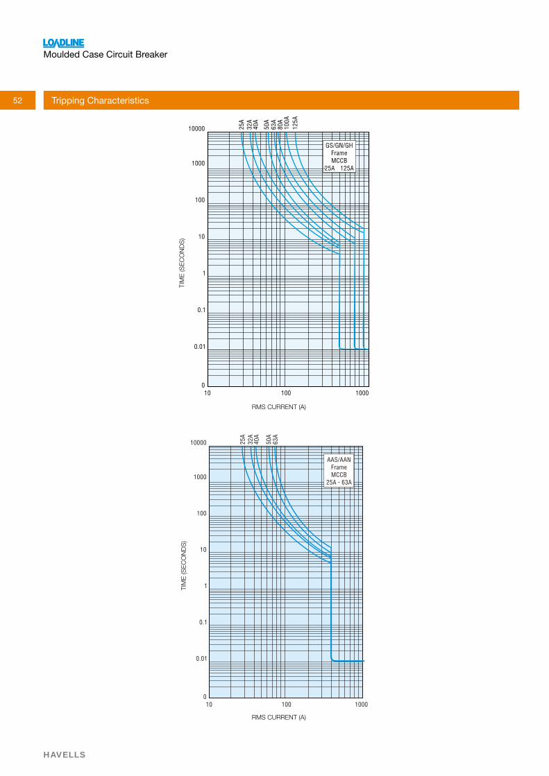
AAS/AANFrame MCCB
EnergyLet Through
52
Moulded Case Circuit Breaker
HAVELLS
RMS CURRENT (A)
RMS CURRENT (A)
TIM
E (S
EC
ON
DS
)TI
ME
(SE
CO
ND
S)
Tripping Characteristics

53
Moulded Case Circuit Breaker
HAVELLS
RMS CURRENT (A)
TIM
E (S
EC
ON
DS
)
Tripping Characteristics

54
Moulded Case Circuit Breaker
HAVELLS
Tripping Characteristics
RMS CURRENT (A)
RMS CURRENT (A) RMS CURRENT (A)
TIM
E (S
EC
ON
DS
)
TIM
E (S
EC
ON
DS
)
0
0.01
0.1
1
10
100
1000
10000 400A
630A
100 1000 10000
CN/CHFrame MCCB
400A-630A
TIM
E (S
EC
ON
DS
)
DN Frame MCCB
1000A-1600A

55
Moulded Case Circuit Breaker
HAVELLS
Ambient Temperature Compensation Chart (G, AA, C Frame MCCBs)
AMBIENT TEMPERTURE (0C)
CO
MP
EN
SAT
ION
fAC
TOR
(% O
F C
UR
RE
NT
RAT
ING
, i)

56
Moulded Case Circuit Breaker
HAVELLS
The
abov
e ta
ble
give
s fa
ult c
urre
nts
in a
mpe
res
till w
hich
leve
l the
dow
nstre
am b
reak
ers
shal
l act
prio
r to
the
upst
ream
bre
aker
.
DIS
CR
IMIN
ATIO
N D
ATA
Pro
duc
t R
ATIN
G
KA
@
LOA
DLI
NE
AA
S/A
AN
LO
AD
LIN
E C
N/C
H
LO
AD
LIN
E D
N
8
0
25
1
60
0 1
60
0
16
00
2
50
0
30
00
4
00
0
50
00
6
30
0
80
00
9
20
0
92
00
9
20
0
1
00
2
5
16
00
16
00
1
60
0
25
00
3
00
0
40
00
5
00
0
63
00
8
00
0
92
00
9
20
0
92
00
1
25
2
5
16
00
16
00
1
60
0
25
00
3
00
0
40
00
5
00
0
63
00
8
00
0
92
00
9
20
0
92
00
1
60
2
5
25
00
3
00
0
40
00
5
00
0
63
00
8
00
0
92
00
9
20
0
92
00
2
00
2
5
25
00
3
00
0
40
00
5
00
0
63
00
8
00
0
92
00
9
20
0
92
00
4
00
5
0
5
00
0
63
00
8
00
0
92
00
9
20
0
92
00
5
00
5
0
63
00
8
00
0
92
00
9
20
0
92
00
6
30
5
0
8
00
0
92
00
9
20
0
92
00
8
00
5
0
92
00
9
20
0
92
00
1
00
0
50
92
00
9
20
0
1
25
0
50
9
20
0
1
60
0
50
9
20
0

57
Moulded Case Circuit Breaker
HAVELLS
Transformer Protection
Primary side
For the protection of transformer with a circuit breaker
inrush current of the transformer must be considered. The peak value of the first current wave often reaches 10-15 times the rated current and may sometimes reach as high as 20-25 times. However, the transient decays
should have a magnetic setting which will not be actuated by the momentary inrush current.
Secondary side
Loadline MCCBs can be used for protection of transformer
device.
Selection table For Transformer Protection
16 25 25 25 25 25 25 40 40 40 40 40 63 100 100 100 100 100 100 160 160 160 160 160 250 250 250 250 200 315 315 250 400 400 315 500 500 400 630 630 500 800 800 630 1000 750 1200
MCCB Rating in Amperes
The rated current of the transformer is calculated as follows :
e
The Breaking capacity of the breaker for protection can be calculated as :
b’ is the rated breaking capacity,
‘Ie’ the rated current
Generator Set Protection
Loadline MCCBs can be used for the effective protection
and short circuits.
The Current rating of MCCB to be selected is calculated as follows :
√ e X I
e
or
Ie
e
Ie
The MCCB rating selected is greater than or equal to the rated current value
Selection Table for DG Set Protection
√ e
Selection & Application
Rating Rating
16 25 25 40 63 100 100 160 160 250 200 315 250 400 315 500 400 630 630 1000 750 1200
Ie
Ib
-3
Ie
√ e

58
Moulded Case Circuit Breaker
HAVELLS
Feeder / Cable Protection
an installation is an important consideration in the selection of the appropriate protective device.
installation.
of the installation and the point at which the short circuit occurs.
earth or phase to neutral.
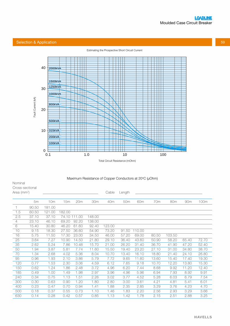
It is possible to arrive at a maximum prospective short circuit
impedance and calculating from the expression :
lengths and sizes of cables between the source of supply
determine the sum of cable resistances and then simply read off the estimated fault current from the relevant transformer curve on the graph.
The values assume a symmetrical fault across the three phases. In a single circuit, for line to neutral faults, take the cable resistance value from the table and double it.
The selection of Loadline MCCB for feeder /cable protection depends on the total load to be protected and the prospective
Ω
ΩΩ
11.00mΩ
ΩΩΩ
57.00mΩ
The above calculations have an inbuilt safety margin as they assume a no impedance fault condition which would not be the case in practice.
Selection & Application
√
1000kVAtransformer
70 meters 4c 120mm2
20 meters 2c 16mm2
A
B
C
D
10 meters8sc 300mm2
Typical Installation
59
Moulded Case Circuit Breaker
HAVELLS
Maximum Resistance of Copper Conductors at 20oC (μOhm)
Cross-sectional 2
5m 10m 15m 20m 30m 40m 50m 60m 70m 80m 90m 100m
1 90.50 181.001.5 60.50 121.00 182.002.5 37.10 37.10 74.10 111.00 148.00 4 23.10 46.10 69.20 92.20 138.00 6 15.40 30.80 46.20 61.60 92.40 123.0010 9.15 18.30 27.50 36.60 54.90 73.20 91.50 110.0016 5.75 11.50 17.30 23.00 34.50 46.00 57.20 69.00 80.50 103.5025 3.64 7.27 10.90 14.50 21.80 29.10 36.40 43.60 50.90 58.20 65.40 72.7035 2.62 5.24 7.86 10.48 15.70 21.00 26.20 31.40 36.70 41.90 47.20 52.4050 1.94 3.87 5.81 7.74 11.60 15.50 19.40 23.20 27.10 31.00 34.80 38.7070 1.34 2.68 4.02 5.36 8.04 10.70 13.40 16.10 18.80 21.40 24.10 26.8095 0.96 1.93 2.10 3.86 5.79 7.72 9.65 11.60 13.60 15.40 17.40 19.30120 0.77 1.53 2.30 3.06 4.59 6.12 7.65 9.18 10.70 12.20 13.80 15.30150 0.62 1.24 1.86 2.48 3.72 4.96 6.20 7.44 8.68 9.92 11.20 12.40185 0.49 1.00 1.49 1.98 2.97 3.96 4.96 5.96 6.94 7.93 8.92 9.91240 0.34 0.75 1.13 1.51 2.26 3.02 3.77 4.52 5.28 6.03 6.79 7.54300 0.30 0.63 0.90 1.20 1.80 2.80 3.00 3.61 4.21 4.81 5.41 6.01400 0.23 0.47 0.70 0.94 1.41 1.88 2.35 2.85 3.29 3.76 4.23 4.70500 0.18 0.37 0.55 0.73 1.10 1.46 1.83 2.20 2.56 2.93 3.29 3.66630 0.14 0.28 0.42 0.57 0.85 1.13 1.42 1.78 2.15 2.51 2.88 3.25
0.1
10
0
20
30
40
1.0 10 100
100kVA
200kVA
315kVA
500kVA
800kVA
1000kVA
1250kVA
1500kVA
2000kVA
Estimating the Prospective Short Circuit Current
Faul
t Cur
rent
(kA
)
Total Circuit Resistance (mOhm)
Selection & Application

60
Moulded Case Circuit Breaker
HAVELLS
Motor Control
Loadline MCCBs can be used for motor protection. Selection of MCCBs has to be done taking into consideration the starting inrush current, and the system fault levels. Further the selection
DOL Starting
Care is to be taken to avoid nuisance tripping during starting of Squirrel Cage Motors since the inrush current will be in the order
setting is chosen such that it does not trip during starting.
Moto r Ra t i ng App rox . Fu l l D i rec t On L i ne S t a r /De l t a Load Cu r ren t MCCB Ra t i ng /Type MCCB Ra t i ng /Type
HP KW (A ) a t 415V AAN CN/CH AAN CN/CH
10 7 .5 14 25 - 25 -12 .5 9 17 25 - 25 -15 11 21 25 - 25 -20 15 28 32 - 32 -
25 19 35 40 - 40 -
30 22 41 50 - 50 -40 30 52 80 - 63 -50 37 69 100 - 80 -60 45 80 - 100 -
75 55 97 - - 125 -
100 75 125 - - 160 -125 90 156 - 250 - -150 112 190 - 315 - 250175 130 225 - 315 - 315
200 149 255 - 315 - 315
220 160 275 - 400 - 400
250 186 320 - 400 - 500
300 224 375 - 500 - 500
350 261 449 - 630 - 630
400 298 505 - 630 - 630
Selection table for Motor Protection
Star-Delta Starting
starting current due to reduced voltage, the MCCBs do not have a problem in the overload setting. But the transient currents can go upto 12 times the rated current during change over from star to delta which will cause the instantaneous magnetic release to trip the breaker. So proper selection of magnetic pickup level is important for prevention of nuisance tripping during change
It is always recommended to select an MCCB in co-ordination with Contactor and Over Load Relay so as to have the best and optimum benefit of all the devices.
Selection & Application
61
Moulded Case Circuit Breaker
HAVELLS
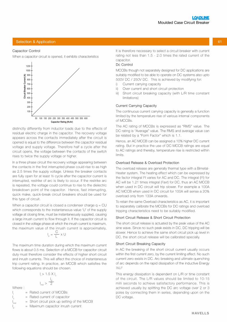
Capacitor Control
distinctly differently from inductor loads due to the effects of residual electric charge in the capacitor. The recovery voltage appears across the contacts immediately after the circuit is opened is equal to the difference between the capacitor residual voltage and supply voltage. Therefore half a cycle after the circuit opens, the voltage between the contacts of the switch rises to twice the supply voltage or higher.
In a three phase circuit the recovery voltage appearing between the contacts in the first interrupted phase could rise to as high
are fully open for at least ½ cycle after the capacitor current is interrupted, restrike of arc is likely to occur. If the restrike arc is repeated, the voltage could continue to rise to the dielectric breakdown point of the capacitor. Hence, fast interrupting, quick make, quick-break circuit breakers should be used for this type of circuit.
voltage at closing time, must be instantaneously supplied, causing a large inrush current to flow through it. If the capacitor circuit is closed in the voltage phase at which the inrush current is maximum, the maximum value of the inrush current is approximately,
The maximum time duration during which the maximum current flows is about 0.5 ms. Selection of a MCCB for capacitor circuit duty must therefore consider the effects of higher short circuit and inrush currents. This will affect the choice of instantaneous trip current rating. In practice, an MCCB which satisfies the following equations should be chosen.
Ir > 1.5 X I
c
I
inst >
Ir
Ic
Iinst
Ip
It is therefore necessary to select a circuit breaker with current rating not less than 1.5 - 2.0 times the rated current of the capacitor.Dc Control
Current Carrying Capacity
The continuous current carrying capacity is generally a function limited by the temperature rise of various internal components of MCCBs.
The AC rating of MCCBs is expressed as “RMS” value. The
be related by a “Form Factor” which is 1.1.
to AC ratings and thereby, temperature rise is restricted within limits.
Overload Release & Overload Protection
The overload release are generally thermal type with a Bimetal-Heater system. The heating effect which can be expressed by the factor integral I2 2
2
overload only from 133A onwards.
To retain the same Overload characteristics as AC, it is important
tripping characteristics need to be suitably modified.
Short Circuit Release & Short Circuit Protection
The short circuit release is actuated by the peak value of the AC
slower. Hence to achieve the same short circuit pick up level in
Short Circuit Breaking Capacity
In AC the breaking of the short circuit current usually occurs
of arc depends on the rapid dissipation of the inductive Energy ½Li2
This energy dissipation is dependent on L/R or time constant of the circuit. The L/R values should be limited to 10-15 milli seconds to achieve satisfactory performance. This is
poles by connecting them in series, depending upon on the
I2
Selection & Application
Ip
CL
![[CATALOGUE TB2-CAT] TEMBREAK 2 MOULDED CASE CIRCUIT BREAKERS · MOULDED CASE CIRCUIT BREAKERS Innovators in Protection Technology [2] MAIN CONTACT / TOGGLE STATUS VISIBILITY TemBreak](https://static.fdocuments.net/doc/165x107/5c1a4ef509d3f2ff0d8b5fef/catalogue-tb2-cat-tembreak-2-moulded-case-circuit-breakers-moulded-case-circuit.jpg)