LOAD FREQUENCY CONTROL FOR A TWO-AREA ... - IRAJ · Load Frequency Control For a Two-Area...
8
International Journal Of Electrical, Electronics And Data Communication, ISSN: 2320-2084 Volume-4, Issue-10, Oct.-2016 Load Frequency Control For a Two-Area Interconnected Power System by Using Sliding Mode Controller 11 LOAD FREQUENCY CONTROL FOR A TWO-AREA INTERCONNECTED POWER SYSTEM BY USING SLIDING MODE CONTROLLER 1 P.GOWRI NAIDU, 2 R.GOVARDHANA RAO 1 PG student of ANITS College, 2 Director of ANITS College, Visakhapatnam, Andhra Pradesh. E-mail: 1 [email protected], 2 [email protected] Abstract— This paper presents the usage of sliding mode Control algorithm for the load frequency control in power systems. A sliding mode based load frequency controller is applied to a two-area power system. Non-reheat and reheat Thermal turbines are distributed in these two areas respectively. The nonlinearities such as governor dead band and generation rate constraint are included in the block diagram of a power plant model. Our control goal is to regulate the load frequency error of the power system in the presences of different load changes and parameter variations. The sliding mode controller (SMC) is simulated on the two-area interconnected power system with nonlinearities. These simulation results shows the robustness of the sliding mode controller. And it also shows that frequency error and tie line power errors are converges to zero. The performance of sliding mode controller is compared with conventional PI controller, PID and fuzzy controllers. This comparisons shows that SMC is the most effective and insensitive to the parameter variations tan the other controllers. Index Terms— Load Frequency Control, Sliding Mode Controller, Governor Dead Band, Generation Rate Constant. I. INTRODUCTION NOW a days the modern electric power systems consist of different power areas which are interconnected with each other by tie lines. The speed of interconnection between any two power areas is measured in frequency. If the generation does not match load changes, the Frequency deviates from its desired value. Since the power system is comprised of interconnected control areas which are linked by tie lines, load changes and generation deficiency lead to both frequency deviation and tie line power changes [1]. The frequency deviation from its Standard value (50Hz) causes high magnetic current in Induction motors or synchronous machines, and hence damages the equipment. Large frequency deviation can also cause the overload of transmission lines, interfere with the system protection schemes, and ultimately result in the failure of operation for the power system [2]. To solve the problem of frequency deviation, a load frequency control (LFC) is applied to the power system. Specifically, LFC has two objectives. One is to maintain the frequency of power systems at 60Hz with a tolerance of 0.5Hz. The other Objective is to maintain the scheduled power interchange of an interconnected power system. Nowadays, in the most of Control areas, PI type controllers with constant parameters are used for the load frequency control [3-6]. However, systems with PI control have more settling time and relatively large overshoots in frequency’s transient responses, and also the PI control algorithm provides required behavior of the system only in a particular area of the nominal operating point, for which it is designed. But, operating point of a power system usually changes continuously, so that characteristics of power plants are not desirable. In the future power systems will be combination of large amounts of distributed generation with large percentage of renewable energy sources, so that the uncertainties will be further increase system and thereby induce new requirements to the load frequency control of that particular power system [7]. In the small time periods each level of frequency regulation must be also expected in the future. In order to reduce the disturbance, advanced controller should be design instead of PI controller which maintain the following specifications 1. Maintaining the control quality over wide operating range 2. Decrease the frequency’s transient responses avoiding the overshoots 3. Insensitive to the parameter variations and robust to the uncertainties in the system 4. And to provide the better disturbance rejection In order to overcome the drawbacks of the pi controller many different control algorithms are proposed. Like fuzzy controller [8-10], model predictive controller [11-12], artificial neural network [13-15], adaptive control algorithms [16-17] and sliding mode control (SMC) [18-22].In these control algorithms also some of the draw backs are present, to eliminate these draw backs a new control scheme is proposed to fulfil the requirements of the load frequency control (LFC). In this paper sliding mode controller is developed to meet the requirements of LFC. Generally, sliding mode controller is a robust control technique that shows very good behavior in controlling systems with parameter variations and external disturbances. The main objective of the sliding mode control is to drive the system trajectory to reach the sliding surface and
Transcript of LOAD FREQUENCY CONTROL FOR A TWO-AREA ... - IRAJ · Load Frequency Control For a Two-Area...
International Journal Of Electrical, Electronics And Data Communication, ISSN: 2320-2084 Volume-4, Issue-10, Oct.-2016
Load Frequency Control For a Two-Area Interconnected Power System by Using Sliding Mode Controller
11
LOAD FREQUENCY CONTROL FOR A TWO-AREA INTERCONNECTED POWER SYSTEM BY USING SLIDING MODE
CONTROLLER
1P.GOWRI NAIDU, 2R.GOVARDHANA RAO
1PG student of ANITS College, 2Director of ANITS College, Visakhapatnam, Andhra Pradesh. E-mail: [email protected], [email protected]
Abstract— This paper presents the usage of sliding mode Control algorithm for the load frequency control in power systems. A sliding mode based load frequency controller is applied to a two-area power system. Non-reheat and reheat Thermal turbines are distributed in these two areas respectively. The nonlinearities such as governor dead band and generation rate constraint are included in the block diagram of a power plant model. Our control goal is to regulate the load frequency error of the power system in the presences of different load changes and parameter variations. The sliding mode controller (SMC) is simulated on the two-area interconnected power system with nonlinearities. These simulation results shows the robustness of the sliding mode controller. And it also shows that frequency error and tie line power errors are converges to zero. The performance of sliding mode controller is compared with conventional PI controller, PID and fuzzy controllers. This comparisons shows that SMC is the most effective and insensitive to the parameter variations tan the other controllers.
Index Terms— Load Frequency Control, Sliding Mode Controller, Governor Dead Band, Generation Rate Constant. I. INTRODUCTION NOW a days the modern electric power systems consist of different power areas which are interconnected with each other by tie lines. The speed of interconnection between any two power areas is measured in frequency. If the generation does not match load changes, the Frequency deviates from its desired value. Since the power system is comprised of interconnected control areas which are linked by tie lines, load changes and generation deficiency lead to both frequency deviation and tie line power changes [1]. The frequency deviation from its Standard value (50Hz) causes high magnetic current in Induction motors or synchronous machines, and hence damages the equipment. Large frequency deviation can also cause the overload of transmission lines, interfere with the system protection schemes, and ultimately result in the failure of operation for the power system [2]. To solve the problem of frequency deviation, a load frequency control (LFC) is applied to the power system. Specifically, LFC has two objectives. One is to maintain the frequency of power systems at 60Hz with a tolerance of 0.5Hz. The other Objective is to maintain the scheduled power interchange of an interconnected power system. Nowadays, in the most of Control areas, PI type controllers with constant parameters are used for the load frequency control [3-6]. However, systems with PI control have more settling time and relatively large overshoots in frequency’s transient responses, and also the PI control algorithm provides required behavior of the system only in a particular area of the nominal operating point, for which it is designed. But, operating point of a power system usually changes continuously, so that characteristics of power plants
are not desirable. In the future power systems will be combination of large amounts of distributed generation with large percentage of renewable energy sources, so that the uncertainties will be further increase system and thereby induce new requirements to the load frequency control of that particular power system [7]. In the small time periods each level of frequency regulation must be also expected in the future. In order to reduce the disturbance, advanced controller should be design instead of PI controller which maintain the following specifications
1. Maintaining the control quality over wide operating range
2. Decrease the frequency’s transient responses avoiding the overshoots
3. Insensitive to the parameter variations and robust to the uncertainties in the system
4. And to provide the better disturbance rejection In order to overcome the drawbacks of the pi controller many different control algorithms are proposed. Like fuzzy controller [8-10], model predictive controller [11-12], artificial neural network [13-15], adaptive control algorithms [16-17] and sliding mode control (SMC) [18-22].In these control algorithms also some of the draw backs are present, to eliminate these draw backs a new control scheme is proposed to fulfil the requirements of the load frequency control (LFC). In this paper sliding mode controller is developed to meet the requirements of LFC. Generally, sliding mode controller is a robust control technique that shows very good behavior in controlling systems with parameter variations and external disturbances. The main objective of the sliding mode control is to drive the system trajectory to reach the sliding surface and
International Journal Of Electrical, Electronics And Data Communication, ISSN: 2320-2084 Volume-4, Issue-10, Oct.-2016
Load Frequency Control For a Two-Area Interconnected Power System by Using Sliding Mode Controller
12
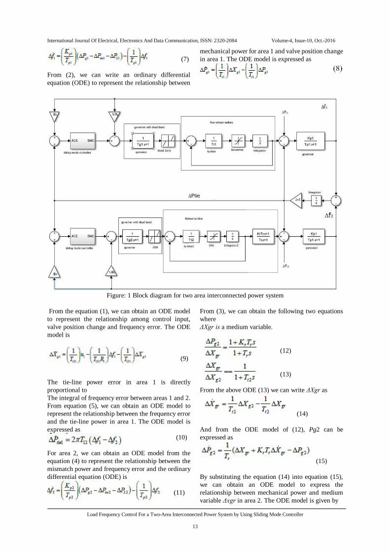
then continues on that surface. When the trajectory is on the surface, system invariance to particular uncertainties and parameter variations is guaranteed. II. MATHEMATICAL MODEL OF POWER SYSTEM WITH NONLINEARITIES In this paper the nonlinear model of power plant consists of two interconnected control areas as shown in the figure.1 .and the inter connected power system is thermal power system and the each control area consists of a generator, a governor a turbine and a sliding mode based load frequency control. In these two control areas the reheat and non-reheat turbines are distributed in the two areas respectively. In these control areas two nonlinearities are introduced such as governor dead band (GDB) and generator rate constant (GRC) [23-24]. In the Fig. 1,ǁPLi is the load disturbance in area i, where =1 or 2, fi is the frequency error in area i, Ptie is the tie-line power change between area i and the other area, ACEi is the area control error in area i , i is the control input in area i, Bi is the frequency response coefficient of area i, Ri is the speed droop coefficient of area i , T12 and T21 are the tie-line coefficients in area 1 and area 2 respectively, ΔXgi is the valve/gate position change for the power system in area i, and ΔPgi is the mechanical power in area i .A governor is mainly designed for improving the frequency response in about 20 seconds following disturbances (such as generator losses). The transfer function of a governor GH (s) is
Where TG represents governor time constant
[1], is the input of speed governor and = and is
the change of steam valve position. In Figure. 1, we use TG1 and TG2 to represents the time constants of the governors in areas 1 and 2 respectively. Equation (1) represents the linear model of the governor excluding dead band. A thermal turbine is used to transform the thermal energy from pressurized steam into mechanical power ( ) that is supplied to the generator. The transfer function of a non-reheat turbine GT (s) is expressed by
(2)
Where Tt the steam turbine time constant. The range of Tt Is [1]. Equation (2) represents the linear model of the steam turbine excluding the nonlinearity GRC. The transfer function of a reheat turbine GTRH(s) is shown as
(3)
Where Kr is the coefficient of reheat turbine, and Tr is the time constant of reheat turbine. Equation (3) shows the linear model for the reheat turbine excluding the nonlinearity GRC. A generator converts the mechanical energy received from the steam turbine into electrical power. The transfer function of the generator Gp(s) is given by
(4)
Where Kp is the gain constant of the power system. ΔPL is disturbance of the load power, ΔPtie is the change of the tie-line power of two areas, and Tp is time constant of the power system. Equation (4) represents the linear model of the generator. In Fig. 1, Kp1 and Tp1 to represents the power system gain constant and time constant for the control area 1, and Kp2 and Tp2 represents the power system gain constant and time constant for the control area2. The tie line power error and area control error (ACE) Are defined as
( )
(5) (6) Where j=2 as i=1 and j=1 as i=2. The area control error (ACE) includes both frequency error and tie line power error. In generally, the governor is nonlinear in nature. It includes a property of dead band as shown in Figure. 1. According to reference [25], “By changing the input signal, the governor may not immediately react until the input reaches to the specified value. Governor dead band (GDB) is defined as the total magnitude of speed change even though there is no resulting change in valve position.” The range of the dead band must be 0.036 Hz for the power system with an operating frequency of 60 Hz. As the change of input frequency is ranging between ±0.036Hz, there are no output responses for the governor. The block diagram represents controlling of a nonlinear inter connected two area power system by using sliding mode controller (SMC) is shown in the figure 1. In the following mathematical equation development, we are assuming that Zero initial conditions for system variables and their derivatives. For area 1, we can obtain an ODE (Ordinary Differential Equation) model from (4) to represent the relationship between the frequency error ( and the mismatch power ( L1- tie1) The ODE model is given by
International Journal Of Electrical, Electronics And Data Communication, ISSN: 2320-2084 Volume-4, Issue-10, Oct.-2016
Load Frequency Control For a Two-Area Interconnected Power System by Using Sliding Mode Controller
13
(7)
From (2), we can write an ordinary differential equation (ODE) to represent the relationship between
mechanical power for area 1 and valve position change in area 1. The ODE model is expressed as
Figure: 1 Block diagram for two area interconnected power system
From the equation (1), we can obtain an ODE model to represent the relationship among control input, valve position change and frequency error. The ODE model is
(9)
The tie-line power error in area 1 is directly proportional to The integral of frequency error between areas 1 and 2. From equation (5), we can obtain an ODE model to represent the relationship between the frequency error and the tie-line power in area 1. The ODE model is expressed as
(10)
For area 2, we can obtain an ODE model from the equation (4) to represent the relationship between the mismatch power and frequency error and the ordinary differential equation (ODE) is
(11)
From (3), we can obtain the following two equations where ΔXgr is a medium variable.
(12)
(13)
From the above ODE (13) we can write ΔXgr as
(14)
And from the ODE model of (12), Pg2 can be expressed as
(15) By substituting the equation (14) into equation (15), we can obtain an ODE model to express the relationship between mechanical power and medium variable Δxgr in area 2. The ODE model is given by
International Journal Of Electrical, Electronics And Data Communication, ISSN: 2320-2084 Volume-4, Issue-10, Oct.-2016
Load Frequency Control For a Two-Area Interconnected Power System by Using Sliding Mode Controller
14
Where Tt2 represents the time constant of steam turbine for area 2. From (1), we can also obtain an ODE model to represent the relationship among control input, frequency error, and valve position change for area 2, is given by
(17)
From the equation (5), the tie-line power for the area 2 can be calculated as
(18)
III. DESIGNING OF SLIDING MODE CONTROLLER FOR LFC 3.1 SMC Design for the nth-order Nonlinear System SMC mainly consists of three parts:
i. Sliding surface function, ii. Reaching control law (or) Switching control
signal, iii. Equivalent control law (or) Equivalent control
signal. The sliding surface function is used to define the desired state trajectories. Switching control signal is a discontinuous control law driving system states to converge to the sliding surface, and Equivalent control law is a continuous control law forcing the system states to remain on the sliding surface. Therefore, the purpose of SMC is to drive the system trajectory to a sliding surface and to maintain the trajectory on the sliding surface in subsequent time. In order to designing sliding mode controllers the main objective is “Selection sliding surface function for that particular system”. Whenever a system’s trajectory is above or below the sliding surface, the gain of the switching controller will be change, so as to move the trajectory back to the surface. Consider an nth-order nonlinear system as
(19)
In equation (19), is the system output, or f is the nonlinear dynamic function
of system states and time and is the coefficient of the control input. The Sliding surface is defined as
(20)
Where is a strictly positive constant, and is the error between the real output and desired output . after that the sliding surface function is defined, and the switch control law is used to force the system states to reach the sliding surface even if there is a disturbance. The switch control law is defined as
(21)
Where is a switching control law, k is a positive gain, and
is a sign function of sliding surface . The switching control has only two output signals, and the sign of switching control is decided by the sign of the sliding surface. If the sign of sliding surface is positive, then the switching control law is positive and vice versa. The equivalent control is used to keep the system states and the trajectory remains stay on the sliding surface. An equivalent control law can be compensate uncertainties present in the system. Since it estimates the quantity of frequency in the real system. The procedure for developing an equivalent control law is given as below. Differentiating the sliding surface, results that
(22)
Substituting equation (19) into equation (22), then
(23) In (23), the omitting part represents the lower- order nonlinear systems given by equation (19), the highest order of which is ranging from 1 to n-1. We define the estimate of
In order to make the derivative of sliding surface zero, we have to choose the equivalent control input as
(24)
The omitted part in (24), is same as the one in (23). The stability of SMC is tested by using Lyapunov’s direct method. The positive definite function V of Lyapunov’s direct method considered as
(25)
International Journal Of Electrical, Electronics And Data Communication, ISSN: 2320-2084 Volume-4, Issue-10, Oct.-2016
Load Frequency Control For a Two-Area Interconnected Power System by Using Sliding Mode Controller
15
Where s is the sliding surface function. If the derivative of equation (25) is negative definite, the system will be asymptotically stable. The sliding mode control law is a linear combination of “both switch control law and equivalent control law”. It is represented by
(26)
By replacing in (23) with in (26), we can Obtain the equation as follows
We suppose that or ( ) is an accurate Estimation of , i.e. now Substituting equation (27) into the derivative of the Lyapunov function, we have
(28) If k is chosen as large enough for the following inequality is satisfied.
(29)
By using the above equation we can check the stability of SMC. Based on the above development, we can design siding mode controllers to control of two interconnected areas with non-reheat and reheat turbines respectively. Our main goal is to drive the frequency error, area control error (ACE) and tie-line power error to zero in both areas. 3.2 SMC Design for the Area with Non-reheat Turbine In order to design the sliding mode controller (SMC) for area 1 with a non-reheat turbine, we define , which the frequency error in area 1 is. From (4), the relationship between the frequency error and the mismatch power in area 1 is
(30)
From the equation (30), we can obtain the model as
From (2), the relationship between valve position change and the mechanical power is
(32)
Substituting (31) into (32), we can obtain the ODE model as
(33)
From (1), the relationship between control signal and valve position change is developed as
(34)
The ODE model of equation (34) is (35)
Substituting (33) into (35) results (36)
Equation (36) shows a third-order ODE model for the frequency error in area 1. So here number variables are three. According to (20), we select the sliding surface as
(37)
In (37), the desired frequency error is zero. So we have (38)
International Journal Of Electrical, Electronics And Data Communication, ISSN: 2320-2084 Volume-4, Issue-10, Oct.-2016
Load Frequency Control For a Two-Area Interconnected Power System by Using Sliding Mode Controller
16
According to (37) and (38), the derivative of the sliding Surface defined as
(39)
In order to derive the equivalent control law, the derivative of the sliding surface must be zero. Substituting (36) into (39), we can derive the equivalent Control law as follows.
(40)
As explained in Section 3.1, the SMC control law can be chosen as a linear combination of an equivalent control law and the switch control law, which is a sign function. Therefore, we have the control signal of SMC for area 1 as
(41)
Where k1 is a positive controller gain for a switch controller. 3.3 SMC Design for the Area with Reheat Turbine The following development is for the design of SMC for area 2 with a reheat turbine. We define , which the frequency error in area 2 is. From (4), the relationship between the frequency error and the mismatched power in area 2 is derived as
(42)
Similarly as control area 1, we can design the control signal of SMC for reheat turbine as area2. In the area 2, the number of state variables are four. Based on the equation (22) the sliding surface defined as
(43)
The desired frequency error is zero. So we have
The derivative of the sliding surface is
(44) Let the
derivative of the sliding surface be equal to zero. We have the equivalent control law:
Where
(46)
The control effort of SMC (w) in area 2 is a linear combination of an equivalent control law and a switch control law. It can be represented as
(48)
Where K2 is a positive controller gain for the switch controller. IV. SIMULATION RESULTS
We simulate PID, fuzzy and SMC controllers on a two-area Interconnected power system in Matlab/Simulink. Here we Select PID and fuzzy control method as a comparison with SMC and Particularly the nonlinearities including GDB and GRC are included in the power system model for our simulations. We choose maximum GDB which is 0.036 Hz, and the maximum GRC with a rate of change as 3% per minute.
International Journal Of Electrical, Electronics And Data Communication, ISSN: 2320-2084 Volume-4, Issue-10, Oct.-2016
Load Frequency Control For a Two-Area Interconnected Power System by Using Sliding Mode Controller
17
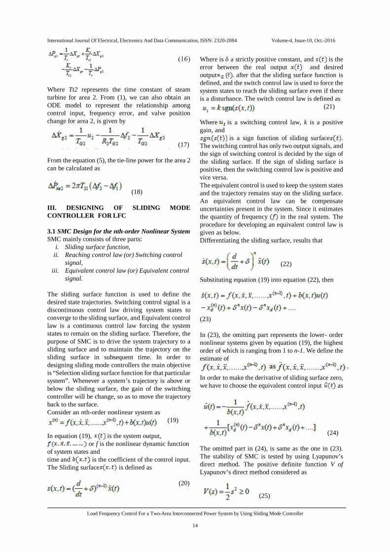
Fig: 2 Frequency error for area 1
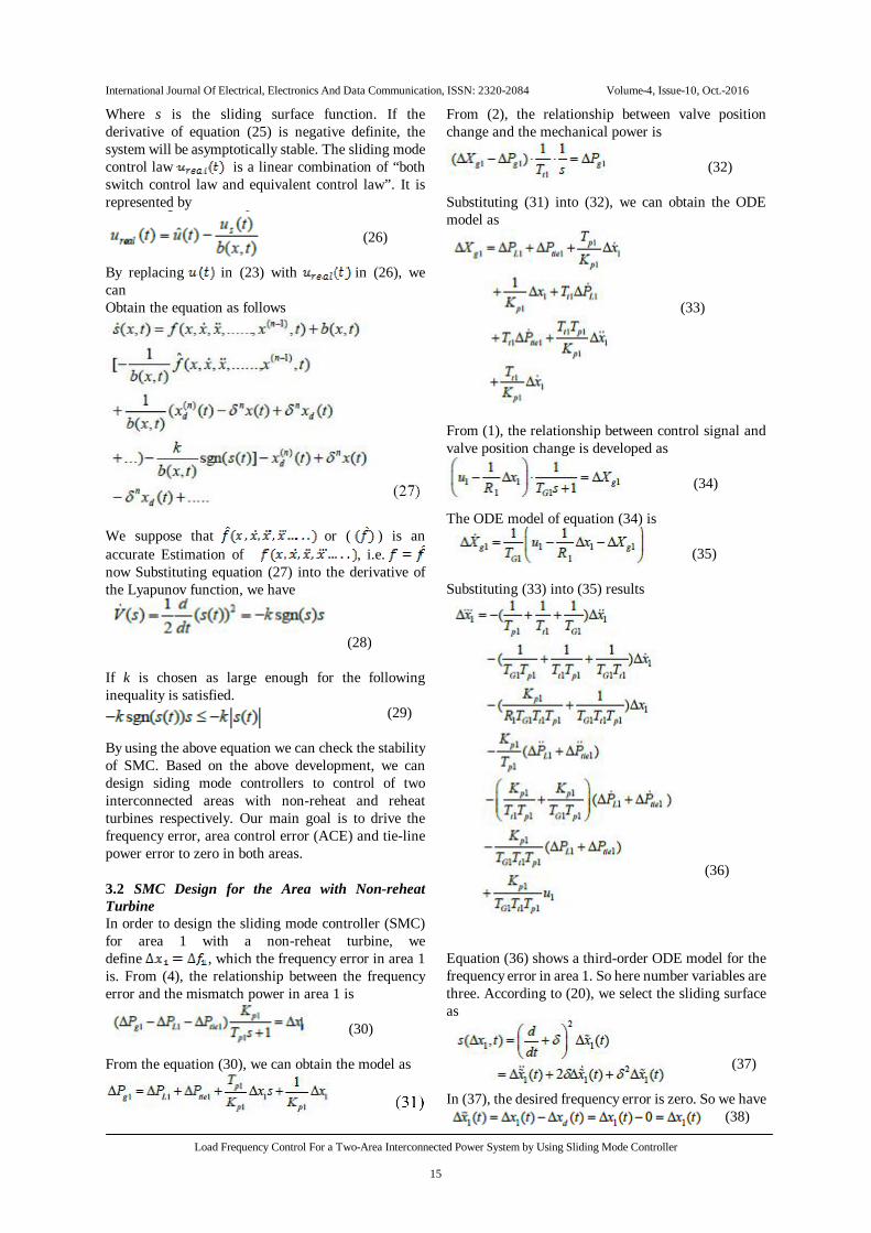
Fig: 3 Frequency error for area 2
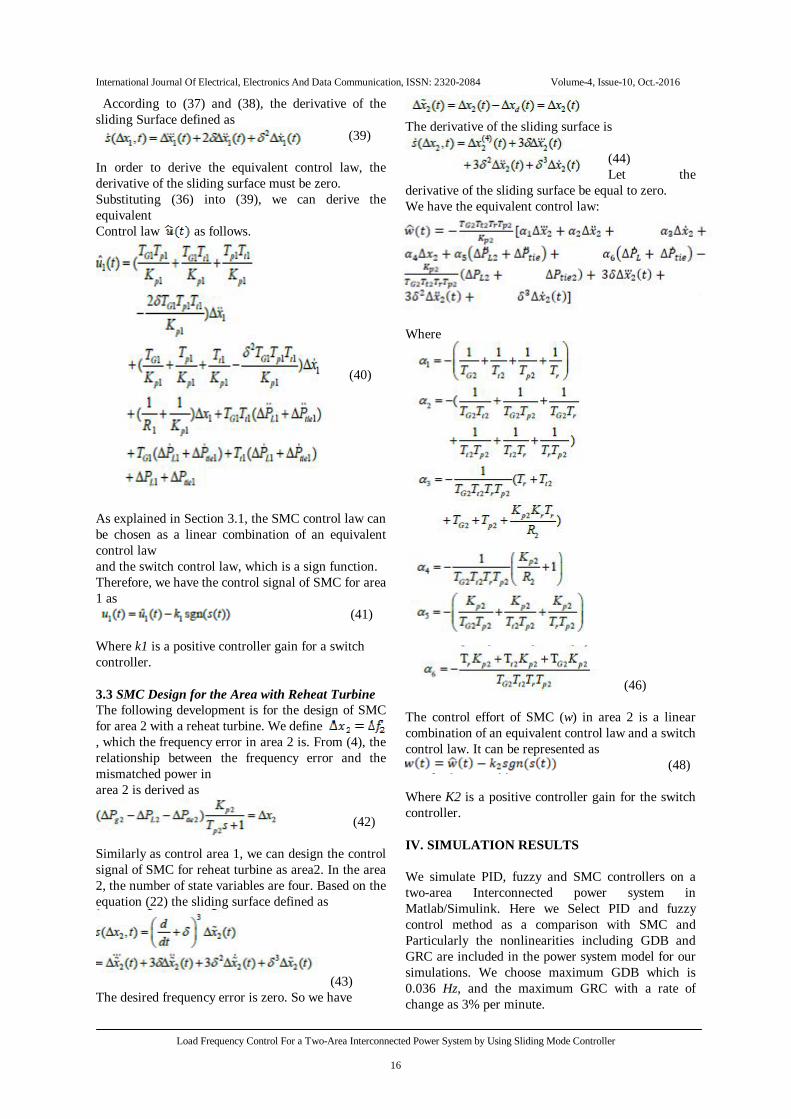
Fig: 4 Tie line power error
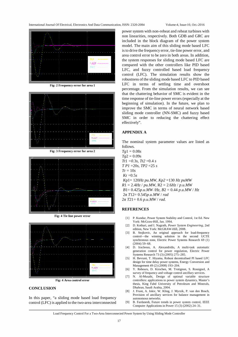
Fig: 4 Area control error
CONCLUSION In this paper, “a sliding mode based load frequency control (LFC) is applied to the two-area interconnected
power system with non-reheat and reheat turbines with non linearities, respectively. Both GDB and GRC are included in the block diagram of the power system model. The main aim of this sliding mode based LFC is to drive the frequency error, tie-line power error, and area control error to be zero in both areas. In addition, the system responses for sliding mode based LFC are compared with the other controllers like PID based LFC, and fuzzy controlled based load frequency control (LFC). The simulation results show the robustness of the sliding mode based LFC to PID based LFC in terms of settling time and overshoot percentage. From the simulation results, we can see that the chattering behavior of SMC is evident in the time response of tie-line power errors (especially at the beginning of simulation). In the future, we plan to improve the SMC in terms of neural network based sliding mode controller (NN-SMC) and fuzzy based SMC in order to reducing the chattering effect effectively”. APPENDIX A The nominal system parameter values are listed as follows. Tg1 = 0.08s Tg2 = 0.09s Tt1 =0.3s, Tt2 =0.4 s T P1 =20s, TP2 =25 s Tr = 10s Kr =0.5s Kp1= 120Hz pu.MW, Kp2 =130 Hz puMW R1 = 2.4Hz / pu.MW, R2 = 2.6Hz / p.u.MW B1= 0.425p.u.MW /Hz, B2 = 0.44 p.u.MW / Hz 2π T12= 0.545p.u.MW / rad 2π T21= 0.6 p.u.MW / rad.
REFERENCES
[1] P. Kundur, Power System Stability and Control, 1st Ed. New York: McGraw-Hill, Jan. 1994.
[2] D. Kothari, and I. Nagrath, Power System Engineering, 2nd edition, New York: McGRAW-Hill, 2008.
[3] B. Stojkovic, An original approach for load-frequency control—the winning solution in the second UCTE synchronous zone, Electric Power Systems Research 69 (1) (2004) 59–68.
[4] D. Iracleous, A. Alexandridis, A multi-task automatic generation control for power regulation, Electric Power Systems Research 73 (3) (2005) 275–285.
[5] H. Bevrani, T. Hiyama, Robust decentralised PI based LFC design for time delay power systems, Energy Conversion and Management 49 (2) (2008) 193–204.
[6] Y. Rebours, D. Kirschen, M. Trotignon, S. Rossignol, A survey of frequency and voltage control ancillary services.
[7] N. Al-Musabi, Design of optimal variable structure controllers: applications to power system dynamics, Master’s thesis, King Fahd University of Petroleum and Minerals, Dhahran, Saudi Arabia, 2004.
[8] J. Frunt, A. Jokic, W. Kling, J. Myrzik, P. van den Bosch, Provision of ancillary services for balance management in autonomous networks.
[9] B. Fardanesh, Future trends in power system control, IEEE Computer Applications in Power 15 (3) (2002) 24–31.
International Journal Of Electrical, Electronics And Data Communication, ISSN: 2320-2084 Volume-4, Issue-10, Oct.-2016
Load Frequency Control For a Two-Area Interconnected Power System by Using Sliding Mode Controller
18
[10] P. Ibraheem, D. Kumar, Kothari, Recent philosophies of automatic generation control strategies in power systems, IEEE Transactions on Power Systems 20 (1) (2005) 246–357.
[11] H. Shayeghi, H. Shayanfar, A. Jalili, Load frequency control strategies: a stateof- the-art survey for the researcher, Energy Conversion and Management 50 (2) (2008) 344–353.
[12] I. Ngamroo, C. Taeratanachai, S. Dechanupaprittha, Y. Mitani, Enhancement of load frequency stabilization effect of superconducting magnetic energy storage by static synchronous series compensator based on Hoo control, Energy Conversion and Management 48 (4) (2006) 1302–1312.
[13] E. Cam, Application of fuzzy logic for load frequency control of hydro-electrical power plants, Energy Conversion and Management 48 (4) (2007) 1281–1288.
[14] H. Lee, J. Park, Y. Joo, Robust load-frequency control for uncertain nonlinear power systems: a fuzzy logic approach, Information Sciences 176 (23) (2006) 3520–3537.
[15] S. Pothiya, I. Ngamroo, S. Runggeratigul, P. Tantaswadi, Design of optimal fuzzy logic based pi controller using multiple tabu search algorithm for load frequency control, Control, Automation, and Systems 4 (2) (2006) 155–164.
[16] A. Hemeida, Wavelet neural network load frequency controller, Energy Conversion and Management 46 (9–10) (2005) 1613–1630.
[17] Y. Oysal, A.S. Yilmaz, E. Koklukaya, A dynamic wavelet network based load frequency control in power systems, International Journal of Electrical Power & Energy Systems 27 (1) (2005) 21–29.
[18] H.Shayeghi, H. Shayanfar, Application of ANN technique based on _-synthesis to load frequency control of interconnected power system, International Journal of Electrical Power & Energy Systems 28 (7) (2006) 503–511.
[19] N. Atic, A. Feliachi, D. Rerkpreedapong, CPS1 and CPS2 compliant wedge-shaped model predictive load frequency control, in: Proceedings of the 2004 IEEE Power Engineering Society General Meeting, 2004, pp. 855–860.
[20] A. Venkat, I. Hiskens, J. Rawlings, S. Wright, Distributed output feedback MPC for power system control.
[21] A.Demiroren, H.Zeynelgil, GA application to optimization of AGC in three-area power system after deregulation, Electrical Power and Energy Systems 29 (3) (2007) 230–240.
[22] C. Parisses, N. Asimopoulos, P. Fessas, Decentralized load-frequency control of a two-area power system via linear programming and optimization techniques, in: Proceedings of the 5th International Conference on Technology and Automation, Thessaloniki, Greece, 2005, pp. 204–209.
[23] [23] S. Velusami, I. Chidambaram, Decentralized biased dual mode controllers for load frequency control of interconnected power systems considering GDB and GRC non-linearities, Energy Conversion and Management 48 (5) (2007) 1691–1702.
[24] Lu CF, Liu CC (1995) Effect of battery energy storage system on load frequency control considering governor dead-band and generation rate constraint. IEEE Trans Energy Convers 10(3):


![Distributed Automatic Load-Frequency Control with ... · system-wide optimal load control techniques as an unresolved task. For load-side frequency control, centralized methods [12],](https://static.fdocuments.net/doc/165x107/5ec3974128e52e6e5318465f/distributed-automatic-load-frequency-control-with-system-wide-optimal-load-control.jpg)