Document Imaging Solutions Load Balancing with F5 Big IP ...
Load Balancing Medical Imaging & Information System Protocols
Deployment Guidev1.1.2
Copyright © Loadbalancer.org

Table of Contents
1. About this Guide..........................................................................................................................................3
2. Loadbalancer.org Appliances Supported..........................................................................................3
3. Loadbalancer.org Software Versions Supported............................................................................3
4. Medical Systems Supported...................................................................................................................3
5. Medical Imaging and Information Systems & Components.......................................................4Picture Archiving and Communication System (PACS).............................................................................................4
Vendor Neutral Archive (VNA)............................................................................................................................................ 4
Imaging Modalities................................................................................................................................................................. 4
Health Care Administration Systems............................................................................................................................... 4
Workstations/Viewers........................................................................................................................................................... 4
6. Medical Information System Standards & Protocols.....................................................................5DICOM....................................................................................................................................................................................... 5
HL7.............................................................................................................................................................................................. 5
IHE XDS...................................................................................................................................................................................... 5
7. Load Balancing Overview........................................................................................................................5Basic Concepts........................................................................................................................................................................ 5
Load Balancer Deployment................................................................................................................................................ 6
Load Balancing Deployment Modes................................................................................................................................ 8
Our Recommendation...................................................................................................................................................... 8
Load Balanced Ports & Services......................................................................................................................................... 8
Persistence (Server Affinity)................................................................................................................................................. 9
Server Health Checking........................................................................................................................................................ 9
8. Loadbalancer.org Appliance – the Basics.........................................................................................9Virtual Appliance Download & Deployment.................................................................................................................9
Initial Network Configuration.......................................................................................................................................... 10
Accessing the Web User Interface (WebUI)................................................................................................................. 10
Clustered Pair Configuration............................................................................................................................................ 11
9. Appliance & Server Configuration......................................................................................................12Load Balancing DICOM...................................................................................................................................................... 12
Load Balancing HL7............................................................................................................................................................. 13
Load Balancing XDS (Registry & Repository)............................................................................................................... 15
Load Balancing HTTPS....................................................................................................................................................... 16
10. Testing & Verification...........................................................................................................................18Using the System Overview.............................................................................................................................................. 18
System Logs & Reports....................................................................................................................................................... 19
11. Technical Support..................................................................................................................................19
12. Further Documentation.......................................................................................................................19
13. Conclusion................................................................................................................................................19
14. Appendix...................................................................................................................................................201 - Clustered Pair Configuration – Adding a Slave Unit..........................................................................................20
2 – Solving the ARP Problem........................................................................................................................................... 22
3 - Company Contact Information................................................................................................................................ 23
Medical System Protocols Deployment Guide v1.1.2
About this Guide
1. About this GuideThis guide details the steps required to configure a load balanced Medical Imaging and Information System environment utilizing Loadbalancer.org appliances. It includes details on load balancing DICOM, HL7 & IHE XDS.
For more information about initial appliance deployment, network configuration and using the Web User Interface (WebUI), please also refer to the relevant Administration Manual:
• v7 Administration Manual
• v8 Administration Manual
2. Loadbalancer.org Appliances SupportedAll our products can be used with Medical Imaging and Information Systems. The complete list of models is shown below:
Discontinued Models Current Models *
Enterprise R16 Enterprise R20
Enterprise VA R16 Enterprise MAX
Enterprise VA Enterprise 10G
Enterprise Ultra
Enterprise VA R20
Enterprise VA MAX
* For full specifications of these models please refer to: http://www.loadbalancer.org/products/hardware
3. Loadbalancer.org Software Versions Supported
• V7.6.4 & later
4. Medical Systems Supported
• Any systems that utilizes medical system standards & protocols such as DICOM, HL7, XDS, XDS-1
Medical System Protocols Deployment Guide v1.1.2
Page 3

Medical Imaging and Information Systems & Components
5. Medical Imaging and Information Systems & Components
PICTURE ARCHIVING AND COMMUNICATION SYSTEM (PACS)A picture archiving and communication system (PACS) is a medical imaging technology which provides economical storage and convenient access to images from multiple imaging modalities. Electronic imagesand reports are transmitted digitally via PACS; this eliminates the need to manually file, retrieve, or transport film jackets. The universal format for PACS image storage and transfer is DICOM (Digital Imaging and Communications in Medicine). Non-image data, such as scanned documents, may be incorporated using consumer industry standard formats like PDF (Portable Document Format), once encapsulated in DICOM.
VENDOR NEUTRAL ARCHIVE (VNA)A VNA is an archival system that can be used to store virtually any type of digital data irrespective of the original source of the data. The VNA will also serve that data to any requesting system (with proper authentication and authorization) without regard to the vendor of the system requesting the data. It is the independence from the vendors that provide the source data or the data request that renders it “vendor neutral.” VNA's are also sometimes referred to as a PACS Neutral Archive.
VNA's are distinguished from picture archiving and communication systems by functioning more as a central store for images from many sources and diverse vendors. PACS are proprietary systems that share little, if at all, and are typically scattered around a health-care system.
IMAGING MODALITIESThese are the various sources of medical images and include equipment such as:
• CT (Computed Tomography) scanners
• MRI (Magnetic Resonance Imaging) scanners
• PET (Positron Emission Tomography) scanners
• X-RAY scanners
• Ultrasound scanners
HEALTH CARE ADMINISTRATION SYSTEMSVarious health-care systems are used within hospitals and ideally are interfaced to share data using protocols such as HL7, these include:
• HIS - Hospital Information System
• RIS - Radiology Information System
• PAS - Patient Administration System
• ADT - Admission, Discharge and Transfer System
WORKSTATIONS/VIEWERSTo enable access to stored images and associated data, DICOM workstations are used. These connect directly to the DICOM source. Viewer servers are also used which enable client PC's to view DICOM images using a web browser via HTTPS.
Medical System Protocols Deployment Guide v1.1.2
Page 4

Medical Information System Standards & Protocols
6. Medical Information System Standards & ProtocolsDICOMThe Digital Imaging and Communications in Medicine (DICOM) Standard describes the means of formatting, storing and exchanging medical images and image related information to facilitate the connectivity of medical devices and systems. The DICOM Standard endorsed by the National Electrical Manufacturers Association (NEMA) is a result of joint efforts of users and manufacturers of medical imaging and health-care information technology.
Today, virtually all imaging devices (Modalities) that are used in radiology, such as CT, MRI, Ultrasound, RF, and other digital rooms, supports the DICOM standard for the exchange of images and related information.
HL7Health Level Seven (HL7) is a American National Standards Institute accredited Standards Developing Organization (SDO) operating in the health-care arena. Since its inception, HL7 has specified standards for a large number of application areas. HL7 standards cover generic application fields such as patient administration, patient care, order entry, results reporting, document and financial management. In addition to that, HL7 addresses the departmental information system communication needs of clinical specialties like laboratory medicine and diagnostic imaging. HL7 is the language used for communication between health-care IT systems.
IHE XDSCross-Enterprise Document Sharing (XDS) is focused on providing a standards-based specification for managing the sharing of documents between any health-care enterprise, ranging from a private physician office to a clinic to an acute care in-patient facility and personal health record systems. This is managed through federated document repositories and a document registry to create a longitudinal record of information about a patient within a given clinical affinity domain. These are distinct entities with separate responsibilities:
A Document Repository is responsible for storing documents in a transparent, secure, reliable and persistent manner and responding to document retrieval requests.
A Document Registry is responsible for storing information about those documents so that the documentsof interest for the care of a patient may be easily found, selected and retrieved irrespective of the repository where they are actually stored.
Documents are provided by one or more Document Sources
They are then accessed by one or more Document Consumers
XDS/XDS-I enables sharing of non-DICOM (i.e. JPEG images, scanned documents, text-based documents) information across disparate health-care systems.
7. Load Balancing Overview
BASIC CONCEPTSTo provide resilience and high availability, multiple Virtual Services (VIPs) are configured for the various protocols and systems. Clients and systems then connect to these VIPs rather than directly to the application servers. Each VIP can be configured in one of the following ways:
• Load balanced mode
Load is distributed across all configured servers/endpoints
• Failover mode
The second server is used only when the first server/endpoint fails
Medical System Protocols Deployment Guide v1.1.2
Page 5
Load Balancing Overview
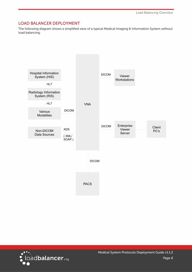
LOAD BALANCER DEPLOYMENTThe following diagram shows a simplified view of a typical Medical Imaging & Information System without load balancing:
Medical System Protocols Deployment Guide v1.1.2
Page 6
VNA
EnterpriseViewerServer
Hospital InformationSystem (HIS)
VariousModalities
Radiology InformationSystem (RIS)
ViewerWorkstations
ClientPC'sNon-DICOM
Data Sources
HL7
DICOM
DICOM
DICOM
HL7
XDS
( XML/SOAP )
PACS
DICOM

Load Balancing Overview
The diagram below shows a highly available system that utilizes multiple system components and load balancing:
Notes:
• VIP (Virtual IP) – This is IP address presented by the load balancer. Clients and other systems connect to this rather than directly to the back end servers/endpoints
• A single load balancer appliance can be used to load balance all services. More that one load balancer appliance may be required depending on throughput and physical network topology
• All Loadbalancer.org models support unlimited VIPs except the Enterprise R20 which supports up to 5 VIPs, each with up to 4 load balanced servers
Medical System Protocols Deployment Guide v1.1.2
Page 7
Hospital InformationSystem (HIS)
VariousModalities
Radiology InformationSystem (RIS)
Non-DICOMData Sources
HTTPS
DICOM
PACS
VIP
HL7 InterfaceServer
HL7 InterfaceServer
VIP
VNA DataReplication
VNA
ViewerWorkstations
ClientPC's
VIP
VIP
VIP
DICOM
HTTPS
VNA
HL7
HL7
HL7
from HL7 Source
Load Balanced HL7
To HL7 destination
DICOM
DICOM HTTPS
DICOM
EnterpriseViewerServer
EnterpriseViewerServer
DICOM
DICOM
XDS(XML/SOAP)
XDS(XML/SOAP)
DICOM
Load Balancing Overview
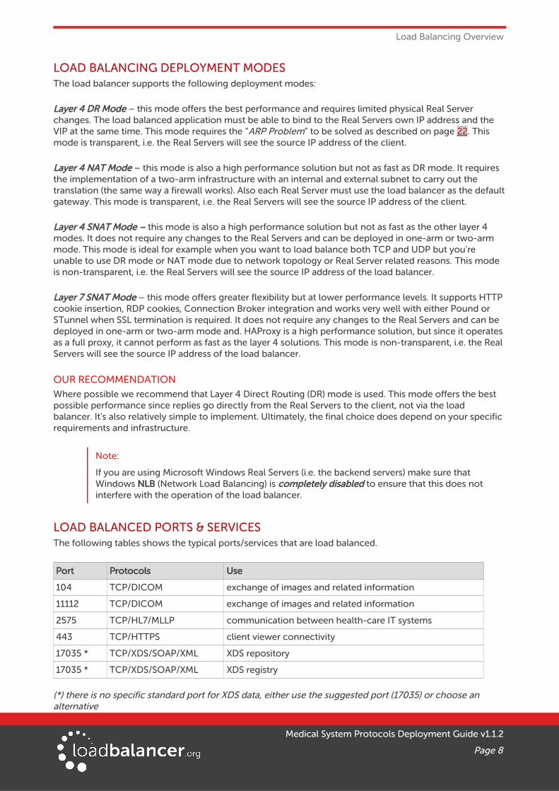
LOAD BALANCING DEPLOYMENT MODESThe load balancer supports the following deployment modes:
Layer 4 DR Mode – this mode offers the best performance and requires limited physical Real Server changes. The load balanced application must be able to bind to the Real Servers own IP address and the VIP at the same time. This mode requires the “ARP Problem” to be solved as described on page 22. This mode is transparent, i.e. the Real Servers will see the source IP address of the client.
Layer 4 NAT Mode – this mode is also a high performance solution but not as fast as DR mode. It requires the implementation of a two-arm infrastructure with an internal and external subnet to carry out the translation (the same way a firewall works). Also each Real Server must use the load balancer as the defaultgateway. This mode is transparent, i.e. the Real Servers will see the source IP address of the client.
Layer 4 SNAT Mode – this mode is also a high performance solution but not as fast as the other layer 4 modes. It does not require any changes to the Real Servers and can be deployed in one-arm or two-arm mode. This mode is ideal for example when you want to load balance both TCP and UDP but you're unable to use DR mode or NAT mode due to network topology or Real Server related reasons. This mode is non-transparent, i.e. the Real Servers will see the source IP address of the load balancer.
Layer 7 SNAT Mode – this mode offers greater flexibility but at lower performance levels. It supports HTTP cookie insertion, RDP cookies, Connection Broker integration and works very well with either Pound or STunnel when SSL termination is required. It does not require any changes to the Real Servers and can be deployed in one-arm or two-arm mode and. HAProxy is a high performance solution, but since it operates as a full proxy, it cannot perform as fast as the layer 4 solutions. This mode is non-transparent, i.e. the Real Servers will see the source IP address of the load balancer.
OUR RECOMMENDATIONWhere possible we recommend that Layer 4 Direct Routing (DR) mode is used. This mode offers the best possible performance since replies go directly from the Real Servers to the client, not via the load balancer. It's also relatively simple to implement. Ultimately, the final choice does depend on your specific requirements and infrastructure.
Note:
If you are using Microsoft Windows Real Servers (i.e. the backend servers) make sure that Windows NLB (Network Load Balancing) is completely disabled to ensure that this does not interfere with the operation of the load balancer.
LOAD BALANCED PORTS & SERVICESThe following tables shows the typical ports/services that are load balanced.
Port Protocols Use
104 TCP/DICOM exchange of images and related information
11112 TCP/DICOM exchange of images and related information
2575 TCP/HL7/MLLP communication between health-care IT systems
443 TCP/HTTPS client viewer connectivity
17035 * TCP/XDS/SOAP/XML XDS repository
17035 * TCP/XDS/SOAP/XML XDS registry
(*) there is no specific standard port for XDS data, either use the suggested port (17035) or choose an alternative
Medical System Protocols Deployment Guide v1.1.2
Page 8

Load Balancing Overview
PERSISTENCE (SERVER AFFINITY)Source IP address persistence is used for all protocols. This ensures that a particular client will connect to the same load balanced server/endpoint for the duration of the session.
SERVER HEALTH CHECKINGThe default health-check used for new VIPs is a TCP port connect. This verifies that the port is open and accepting connections. However, it does not necessarily guarantee that the associated service is fully operational. Also, repeated ongoing connections to the service port may cause multiple log entries reporting incomplete connections or other issues.
More robust service oriented health-checks can be configured for both layer 4 and layer 7 services using the negotiate option. This effectively tests and verifies the running service.
For example, the load balancer can be configured to look for specific content on an HTTP web page on the load balanced Real Server. If the page can be opened and the content can be found, the check will have passed. If not, the check will fail and the server/endpoint will be marked as down.
If the service running is not HTTP based, a custom page could be setup on the load balanced servers that simply indicates service status. The load balancer can then use this for health checking.
The page to check and the content to be verified can easily be configured for layer 4 and layer 7 VIPs usingthe WebUI. Select the required negotiate option and configure the required settings. For more details on configuring health-checks please refer to Chapter 8 in the Administration Manual.
Note:
The configuration examples in this guide use a TCP port connect (the default) to check the health of load balanced servers.
8. Loadbalancer.org Appliance – the Basics
VIRTUAL APPLIANCE DOWNLOAD & DEPLOYMENTA fully featured, fully supported 30 day trial is available if you are conducting a PoC (Proof of Concept) deployment. The VA is currently available for VMware, Virtual Box, Hyper-V, KVM and XEN and has been optimized for each Hypervisor. By default, the VA is allocated 1 CPU, 2GB of RAM and has an 8GB virtual disk. The Virtual Appliance can be downloaded here.
Note:
The same download is used for the licensed product, the only difference is that a license key file(supplied by our sales team when the product is purchased) must be applied using the appliance's WebUI.
Note:
Please refer to the Administration Manual and the ReadMe.txt text file included in the VA download for more detailed information on deploying the VA using various Hypervisors.
Medical System Protocols Deployment Guide v1.1.2
Page 9
Loadbalancer.org Appliance – the Basics
INITIAL NETWORK CONFIGURATIONThe IP address, subnet mask, default gateway and DNS settings can be configured in several ways as detailed below:
Method 1 - Using the Network Setup Wizard at the console
After boot up, follow the instructions on the console to configure the IP address, subnet mask, default gateway and DNS settings.
Method 2 - Using the WebUI
Using a browser, connect to the WebUI on the default IP address/port: http://192.168.2.21:9080
To set the IP address & subnet mask, use: Local Configuration > Network Interface Configuration
To set the default gateway, use: Local Configuration > Routing
To configure DNS settings, use: Local Configuration > Hostname & DNS
Method 3 - Using Linux commands
At the console, set the initial IP address using the following command:
ip addr add <IP address>/<mask> dev eth0
At the console, set the initial default gateway using the following command:
route add default gw <IP address> <interface>
At the console, set the DNS server using the following command:
echo nameserver <IP address> >> /etc/resolv.conf
Note:
If method 3 is used, you must also configure these settings using the WebUI, otherwise the settings will be lost after a reboot
ACCESSING THE WEB USER INTERFACE (WEBUI)The WebUI can be accessed via HTTP at the following URL: http://192.168.2.21:9080/lbadmin
* Note the port number → 9080
The WebUI can be accessed via HTTPS at the following URL: https://192.168.2.21:9443/lbadmin
* Note the port number → 9443
(replace 192.168.2.21 with the IP address of your load balancer if it's been changed from the default)
Login using the following credentials:
Username: loadbalancer
Password: loadbalancer
Note:
To change the password , use the WebUI menu option: Maintenance > Passwords.
Medical System Protocols Deployment Guide v1.1.2
Page 10

Loadbalancer.org Appliance – the Basics
Once logged in, the WebUI will be displayed as shown below:
CLUSTERED PAIR CONFIGURATIONLoadbalancer.org recommend that load balancer appliances are deployed in pairs for high availability. In this guide a single unit is deployed first, adding a secondary slave unit is covered in section 1 of the Appendix on page 20.
Medical System Protocols Deployment Guide v1.1.2
Page 11

Appliance & Server Configuration
9. Appliance & Server Configuration
Load Balancing Mode
As mentioned on page 8, Virtual Services can be configured in one of four fundamental ways, i.e. Layer 4 DR mode, Layer 4 NAT mode, Layer 4 SNAT mode or Layer 7 SNAT mode. The following sections illustrate how to configure the Virtual Services using various modes. If a different mode is required for a particular VIP, please refer to one of the other sections that uses that mode for guidance. Please also don't hesitate to contact our support team: [email protected].
Health-Check Configuration
As mentioned on page 9 , heath checks can be configured in several different ways. The sections below all use a TCP port connect on the service port.
LOAD BALANCING DICOM(Using Layer 4 DR Mode)
Setting up the Virtual Service (VIP)
1. Using the WebUI, navigate to: Cluster Configuration > Layer 4 – Virtual Services and click Add a New Virtual Service
2. Enter the following details:
3. Enter an appropriate name (Label) for the Virtual Service, e.g. DICOM-Modalities
4. Set the Virtual Service IP address field to the required IP address, e.g. 10.12.1.100
5. Set the Virtual Service Ports field to the required port(s), e.g. 104,11112
6. Set Protocol to TCP
7. Set Forwarding Method to Direct Routing
8. Click Update
9. Now click Modify next to the newly created Virtual Service
10. Set Persistent Timeout to 3600 , i.e. 1 hour
11. Set the Check Type to Connect to port (the default)
12. Set the Check Port to the required port - by default this is set to the first port (104)
13. Click Update
Medical System Protocols Deployment Guide v1.1.2
Page 12
Appliance & Server Configuration
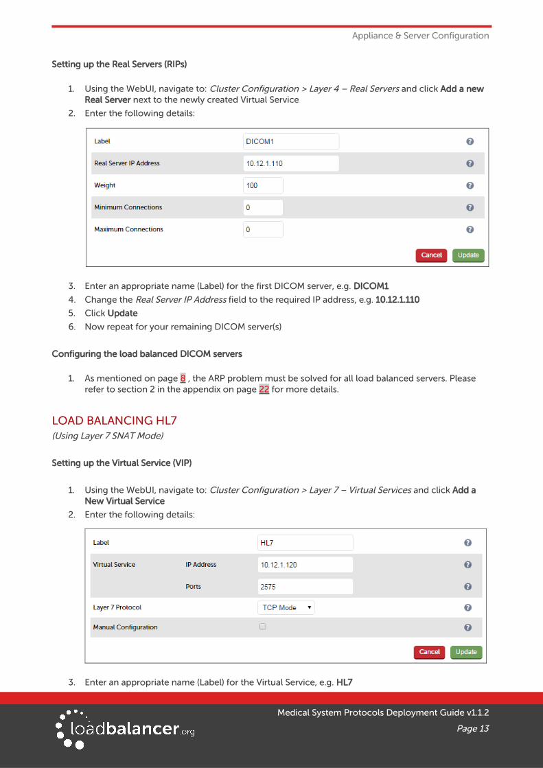
Setting up the Real Servers (RIPs)
1. Using the WebUI, navigate to: Cluster Configuration > Layer 4 – Real Servers and click Add a new Real Server next to the newly created Virtual Service
2. Enter the following details:
3. Enter an appropriate name (Label) for the first DICOM server, e.g. DICOM1
4. Change the Real Server IP Address field to the required IP address, e.g. 10.12.1.110
5. Click Update
6. Now repeat for your remaining DICOM server(s)
Configuring the load balanced DICOM servers
1. As mentioned on page 8 , the ARP problem must be solved for all load balanced servers. Please refer to section 2 in the appendix on page 22 for more details.
LOAD BALANCING HL7(Using Layer 7 SNAT Mode)
Setting up the Virtual Service (VIP)
1. Using the WebUI, navigate to: Cluster Configuration > Layer 7 – Virtual Services and click Add a New Virtual Service
2. Enter the following details:
3. Enter an appropriate name (Label) for the Virtual Service, e.g. HL7
Medical System Protocols Deployment Guide v1.1.2
Page 13

Appliance & Server Configuration
4. Set the Virtual Service IP address field to the required IP address, e.g. 10.12.1.120
5. Set the Virtual Service Ports field to the required port, e.g. 2575
6. Set the Layer 7 Protocol to TCP Mode
7. Click Update
8. Now click Modify next to the newly created Virtual Service
9. Ensure Persistence Mode is set to Source IP
10. Set Persistence Timeout to 1h (i.e. 1 hour)
11. Set Check Port to the required port – leave blank to check the service port (2575)
12. Click Update
Setting up the Real Servers (RIPs)
1. Using the WebUI, navigate to: Cluster Configuration > Layer 7 – Real Servers and click Add a new Real Server next to the newly created Virtual Service
2. Enter the following details:
3. Enter an appropriate name (Label) for the first HL7 server, e.g. HL71
4. Change the Real Server IP Address field to the required IP address, e.g. 10.12.1.130
5. Set the Real Server Port field to 2575
6. Click Update
7. Now repeat for your remaining HL7 server(s)
Configure HAProxy Timeout Settings
1. Using the WebUI, navigate to: Cluster Configuration > Layer 7 – Advanced Configuration
2. Change Client Timeout to 1h as shown above (i.e. 1 hour)
3. Change Real Server Timeout to 1h as shown above (i.e. 1 hour)
4. Click the Update button to save the settings
Medical System Protocols Deployment Guide v1.1.2
Page 14
Appliance & Server Configuration
Restart HAProxy
1. To apply the new settings restart HAProxy using the WebUI option: Maintenance > Restart Servicesand clicking Restart HAProxy
Note:
If you will be configuring additional layer 7 services, you can restart HAProxy once all layer 7 Virtual Services and Real Servers have been defined.
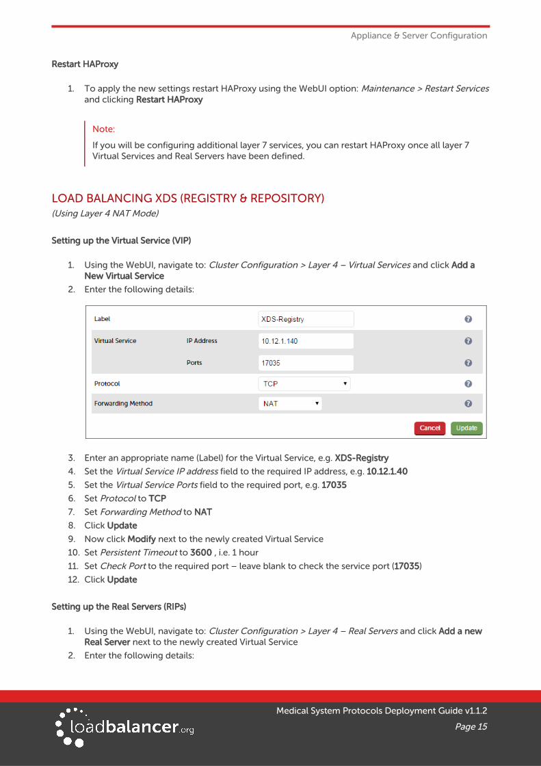
LOAD BALANCING XDS (REGISTRY & REPOSITORY)(Using Layer 4 NAT Mode)
Setting up the Virtual Service (VIP)
1. Using the WebUI, navigate to: Cluster Configuration > Layer 4 – Virtual Services and click Add a New Virtual Service
2. Enter the following details:
3. Enter an appropriate name (Label) for the Virtual Service, e.g. XDS-Registry
4. Set the Virtual Service IP address field to the required IP address, e.g. 10.12.1.40
5. Set the Virtual Service Ports field to the required port, e.g. 17035
6. Set Protocol to TCP
7. Set Forwarding Method to NAT
8. Click Update
9. Now click Modify next to the newly created Virtual Service
10. Set Persistent Timeout to 3600 , i.e. 1 hour
11. Set Check Port to the required port – leave blank to check the service port (17035)
12. Click Update
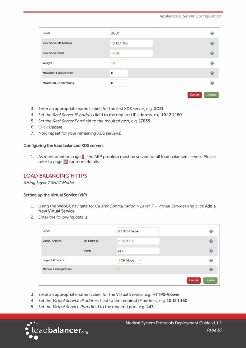
Setting up the Real Servers (RIPs)
1. Using the WebUI, navigate to: Cluster Configuration > Layer 4 – Real Servers and click Add a new Real Server next to the newly created Virtual Service
2. Enter the following details:
Medical System Protocols Deployment Guide v1.1.2
Page 15
Appliance & Server Configuration
3. Enter an appropriate name (Label) for the first XDS server, e.g. XDS1
4. Set the Real Server IP Address field to the required IP address, e.g. 10.12.1.150
5. Set the Real Server Port field to the required port, e.g. 17035
6. Click Update
7. Now repeat for your remaining XDS server(s)
Configuring the load balanced XDS servers
1. As mentioned on page 8 , the ARP problem must be solved for all load balanced servers. Please refer to page 22 for more details.
LOAD BALANCING HTTPS(Using Layer 7 SNAT Mode)
Setting up the Virtual Service (VIP)
1. Using the WebUI, navigate to: Cluster Configuration > Layer 7 – Virtual Services and click Add a New Virtual Service
2. Enter the following details:
3. Enter an appropriate name (Label) for the Virtual Service, e.g. HTTPS-Viewer
4. Set the Virtual Service IP address field to the required IP address, e.g. 10.12.1.160
5. Set the Virtual Service Ports field to the required port, e.g. 443
Medical System Protocols Deployment Guide v1.1.2
Page 16
Appliance & Server Configuration
6. Set the Layer 7 Protocol to TCP Mode
7. Click Update
8. Now click Modify next to the newly created Virtual Service
9. Ensure Persistence Mode is set to Source IP
10. Set Persistence Timeout to 1h (i.e. 1 hour)
11. Set Check Port to the required port – leave blank to check the service port (443)
12. Click Update
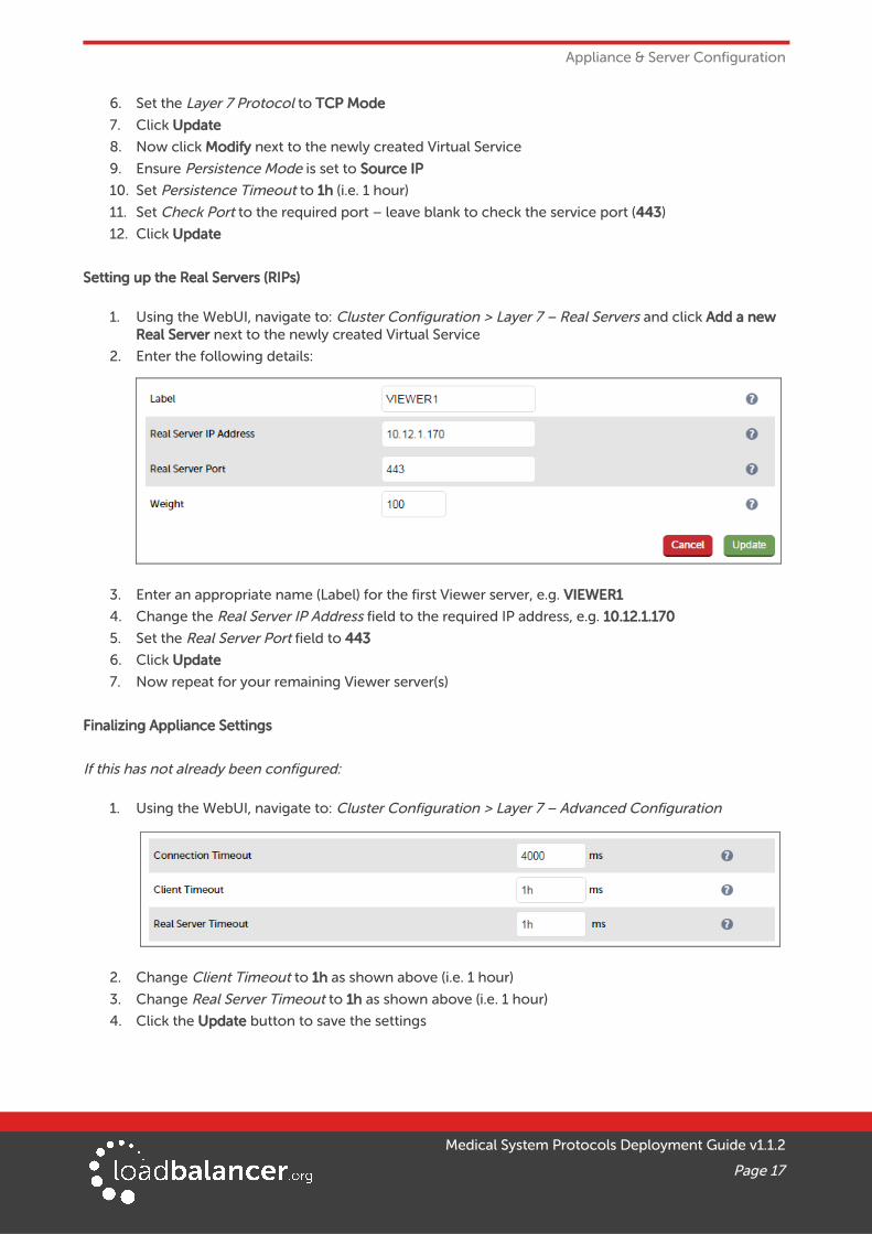
Setting up the Real Servers (RIPs)
1. Using the WebUI, navigate to: Cluster Configuration > Layer 7 – Real Servers and click Add a new Real Server next to the newly created Virtual Service
2. Enter the following details:
3. Enter an appropriate name (Label) for the first Viewer server, e.g. VIEWER1
4. Change the Real Server IP Address field to the required IP address, e.g. 10.12.1.170
5. Set the Real Server Port field to 443
6. Click Update
7. Now repeat for your remaining Viewer server(s)
Finalizing Appliance Settings
If this has not already been configured:
1. Using the WebUI, navigate to: Cluster Configuration > Layer 7 – Advanced Configuration
2. Change Client Timeout to 1h as shown above (i.e. 1 hour)
3. Change Real Server Timeout to 1h as shown above (i.e. 1 hour)
4. Click the Update button to save the settings
Medical System Protocols Deployment Guide v1.1.2
Page 17

Appliance & Server Configuration
Restart HAProxy
1. To apply the new settings restart HAProxy using the WebUI option: Maintenance > Restart Servicesand clicking Restart HAProxy
Note:
If you will be configuring additional layer 7 services, you can restart HAProxy once all layer 7 Virtual Services and Real Servers have been defined.
10. Testing & Verification
USING THE SYSTEM OVERVIEW
Verify that all VIPs & associated RIPs are reported as up (green) as shown below:
If certain servers are down, i.e. failing their health check, they will be highlighted red as shown below:
Medical System Protocols Deployment Guide v1.1.2
Page 18

Testing & Verification
SYSTEM LOGS & REPORTSVarious system logs & reports can be used to help diagnose problems and help solve appliance issues. Logs can be accessed using the WebUI options: Logs & Reports.
11. Technical SupportIf you have any questions regarding the appliance or would like assistance designing your deployment, please don't hesitate to contact our support team: [email protected].
12. Further DocumentationThe Administration Manual contains much more information about configuring and deploying the appliance. It's available here: http://pdfs.loadbalancer.org/loadbalanceradministrationv8.pdf
13. ConclusionLoadbalancer.org appliances provide a very cost effective and flexible solution for highly available load balanced Medical Imaging Systems environments.
Medical System Protocols Deployment Guide v1.1.2
Page 19

Appendix
14. Appendix1 - CLUSTERED PAIR CONFIGURATION – ADDING A SLAVE UNITIf you initially configured just the master unit and now need to add a slave - our recommended procedure,please refer to the relevant section below for more details:
Note:
A number of settings are not replicated as part of the master/slave pairing process and thereforemust be manually configured on the slave appliance. These are listed below:
• Hostname & DNS settings
• Network settings including IP addresses, bonding configuration and VLANs
• Routing configuration including default gateways and static routes
• Date & time settings
• Physical – Advanced Configuration settings including Internet Proxy IP address & port, Firewall table size, SMTP relay and Syslog server
• SNMP settings
• Graphing settings
• Firewall Script & Firewall Lockdown Script settings
• Software updates
Version 7:
Please refer to Chapter 8 – Appliance Clustering for HA in the v7 Administration Manual.
Version 8:
To add a slave node – i.e. create a highly available clustered pair:
1. Deploy a second appliance that will be the slave and configure initial network settings
2. Using the WebUI, navigate to: Cluster Configuration > High-Availability Configuration
Medical System Protocols Deployment Guide v1.1.2
Page 20

Appendix
3. Specify the IP address and the loadbalancer users password (the default is 'loadbalancer') for the slave (peer) appliance as shown above
4. Click Add new node
5. The pairing process now commences as shown below:
6. Once complete, the following will be displayed:
7. To finalize the configuration, restart heartbeat and any other services as prompted in the blue message box at the top of the screen
Note:
Clicking the Restart Heartbeat button on the master appliance will also automatically restart heartbeat on the slave appliance.
Note:
Please refer to chapter 9 – Appliance Clustering for HA in the Administration Manual for more detailed information on configuring HA with 2 appliances.
Medical System Protocols Deployment Guide v1.1.2
Page 21

Appendix
2 – SOLVING THE ARP PROBLEMLayer 4 DR mode works by changing the MAC address of the inbound packets to match the Real Server selected by the load balancing algorithm. To enable DR mode to operate:
• Each Real Server must be configured to accept packets destined for both the VIP address and the Real Servers IP address (RIP). This is because in DR mode the destination address of load balanced packets is the VIP address, whilst for other traffic such as health-checks, administration traffic etc. it's the Real Server's own IP address (the RIP). The service/process (e.g. IIS, httpd) must respond to both addresses.
• Each Real Server must be configured so that it does not respond to ARP requests for the VIP address – only the load balancer should do this.
Configuring the Real Servers in this way is referred to as 'Solving the ARP problem''. The steps required depend on the particular OS being used.
For detailed steps on solving the ARP problem for Linux, Windows and various other operating systems, please refer to the Administration Manual and search for “DR Mode Considerations”.
Medical System Protocols Deployment Guide v1.1.2
Page 22
Appendix
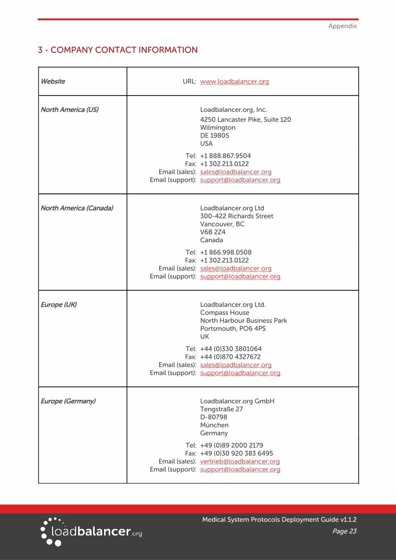
3 - COMPANY CONTACT INFORMATION
Website URL: w w w.loadbalancer.org
North America (US) Loadbalancer.org, Inc.
4250 Lancaster Pike, Suite 120WilmingtonDE 19805USA
Tel:Fax:
Email (sales):Email (support):
+1 888.867.9504+1 [email protected]@loadbalancer.org
North America (Canada) Loadbalancer.org Ltd300-422 Richards StreetVancouver, BCV6B 2Z4Canada
Tel:Fax:
Email (sales):Email (support):
+1 866.998.0508+1 [email protected]@loadbalancer.org
Europe (UK) Loadbalancer.org Ltd.Compass HouseNorth Harbour Business ParkPortsmouth, PO6 4PSUK
Tel:Fax:
Email (sales):Email (support):
+44 (0)330 3801064+44 (0)870 [email protected]@loadbalancer.org
Europe (Germany) Loadbalancer.org GmbHTengstraße 27D-80798MünchenGermany
Tel:Fax:
Email (sales):Email (support):
+49 (0)89 2000 2179+49 (0)30 920 383 [email protected]@loadbalancer.org
Medical System Protocols Deployment Guide v1.1.2
Page 23