LNBA Side Stream Treatment Bailey - Neuse River Stream Treatment... · Side Stream Treatment...
39
WWTP Side Stream Treatment of Nutrients – Considerations for City of Raleigh’s Bioenergy Recovery Project LNBA / NRCA 2017 Wastewater Treatment Plant Operators Training Workshop July 18 and 20, 2017 Erika L. Bailey, PE, City of Raleigh
Transcript of LNBA Side Stream Treatment Bailey - Neuse River Stream Treatment... · Side Stream Treatment...

WWTP Side Stream Treatment of Nutrients – Considerations for City of Raleigh’s Bioenergy Recovery Project
LNBA / NRCA 2017 Wastewater Treatment
Plant Operators Training Workshop
July 18 and 20, 2017
Erika L. Bailey, PE, City of Raleigh

Acknowledgements

Topics for Today’s Presentation
1. Side Stream Treatment Overview• What is side stream treatment?
• Different types of side stream treatment systems
2. Side Stream Treatment Planning for City’s Bioenergy Recovery Project• Bioenergy Recovery Program overview (Quick Recap)
• Drivers for side stream treatment at NRRRF
• Process considerations for treating high strength filtrate
• Side stream treatment systems considered
• LIFT SEE IT site visit of short-cut nitrogen removal systems
• Next Steps

Side Stream Treatment Overview
• Separate treatment of solids handling recycle streams
• Lessen impacts of recycle nutrient loads on main treatment process• Small volume, high nutrient load
• Intermittent solids handling operations can impact peak loads
• Potential to impact main stream nutrient removal process
• Ammonia break through
• Increased air demands
• Increased chemical demands
• Variable performance
What is Side Stream Treatment?

Different Types of Side Stream Treatment
EqualizationBiological Nitrogen Removal Systems
Chemical Phosphorus Removal or Phosphorus
Recovery System

Equalization
• Attenuate flows and/or loads from solids handling operation• Reduce potential for ammonia break through
• Reduce fluctuations on air demands
• Reduce fluctuations on supplemental carbon demands
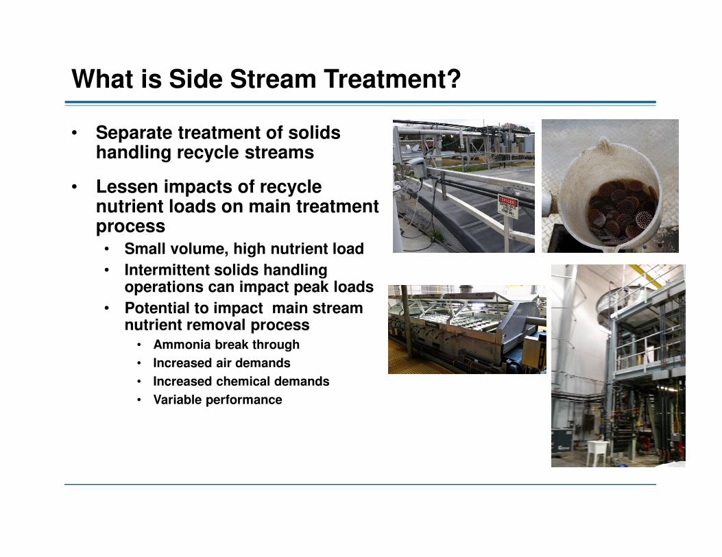
Side Stream Short-Cut Nitrogen Removal
• Biologically treat nitrogen in side stream treatment process
• Often use “Short-Cut” nitrogen cycle • Reduce air required
• Reduce / eliminate carbon
• Several different systems available
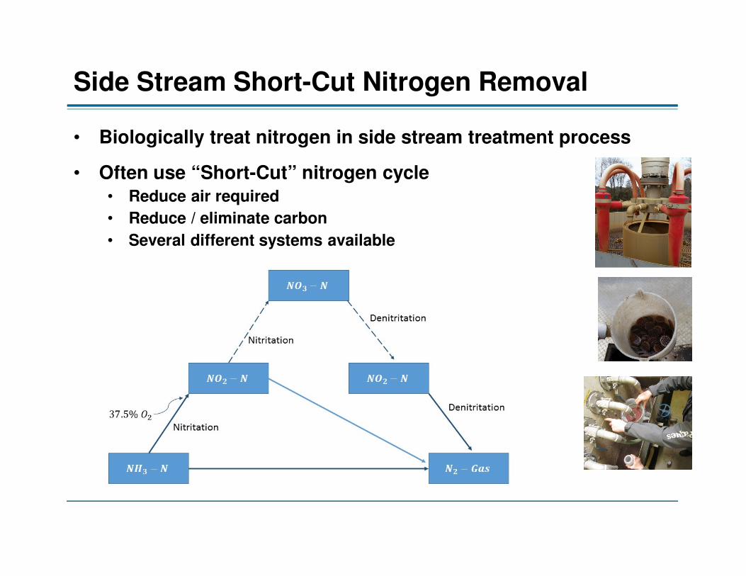
Side Stream Phosphorus Removal
• Add coagulant for chemical phosphorus removal
• Or utilize process to recover phosphorus• Add chemicals to produce struvite in controlled environment
• Obtain phosphorus rich product that can be used as fertilizer
• Several different systems available

Side Stream TreatmentPlanning for Bioenergy Recovery Project
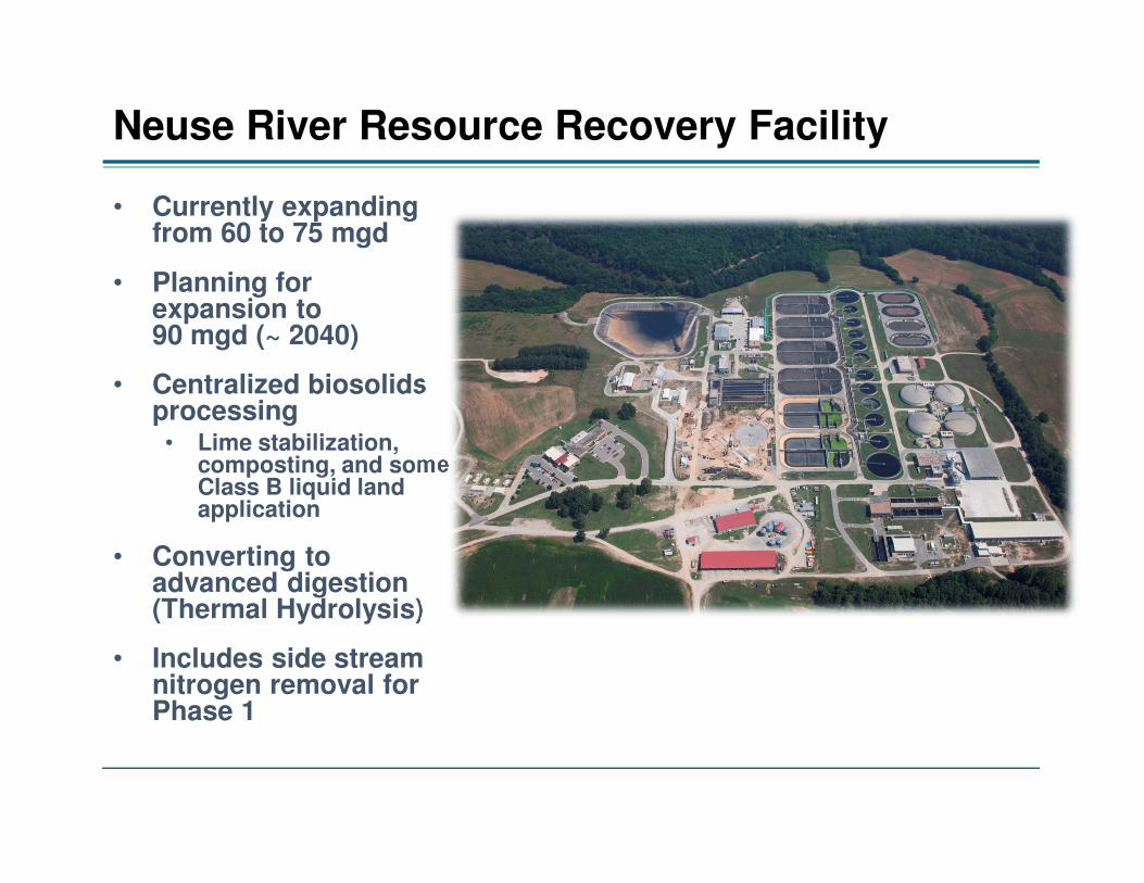
Neuse River Resource Recovery Facility
• Currently expanding from 60 to 75 mgd
• Planning for expansion to 90 mgd (~ 2040)
• Centralized biosolids processing • Lime stabilization,
composting, and some Class B liquid land application
• Converting to advanced digestion (Thermal Hydrolysis)
• Includes side stream nitrogen removal for Phase 1

NRRRF Existing Process Flow Diagram

Proposed Biosolids Process
EQ
CLASS A
CAKE
STORAGEFOG
RECEIVING
SCREENINGS
LOW PRESSURE
GAS STORAGE
Primary
Solids SLUDGE
SCREENS
SCREENED
SLUDGE
PRE-
DEWATERINGTHERMAL
HYDROLYSIS
COOLING SYSTEM
ANAEROBIC
DIGESTERS
SLUDGE
STORAGEFINAL
DEWATERING
SIDESTREAM
NITROGEN
REMOVAL
THICKENING
GAS CLEAN
UP
BIOGAS
BOILERS
STEAM
RETURN
TO HEAD OF PLANT
WAS
BLEND
TANK
CAKE
BIN
RNG
PIPELINE
INJECTION
SCREENINGS
PASTEURIZATION
TWAS
STEAM FROM
BOILERS
FLARE

Visualization of the New Residuals Handling Complex (30-Percent Design Concept)

Side StreamTreatment - Drivers
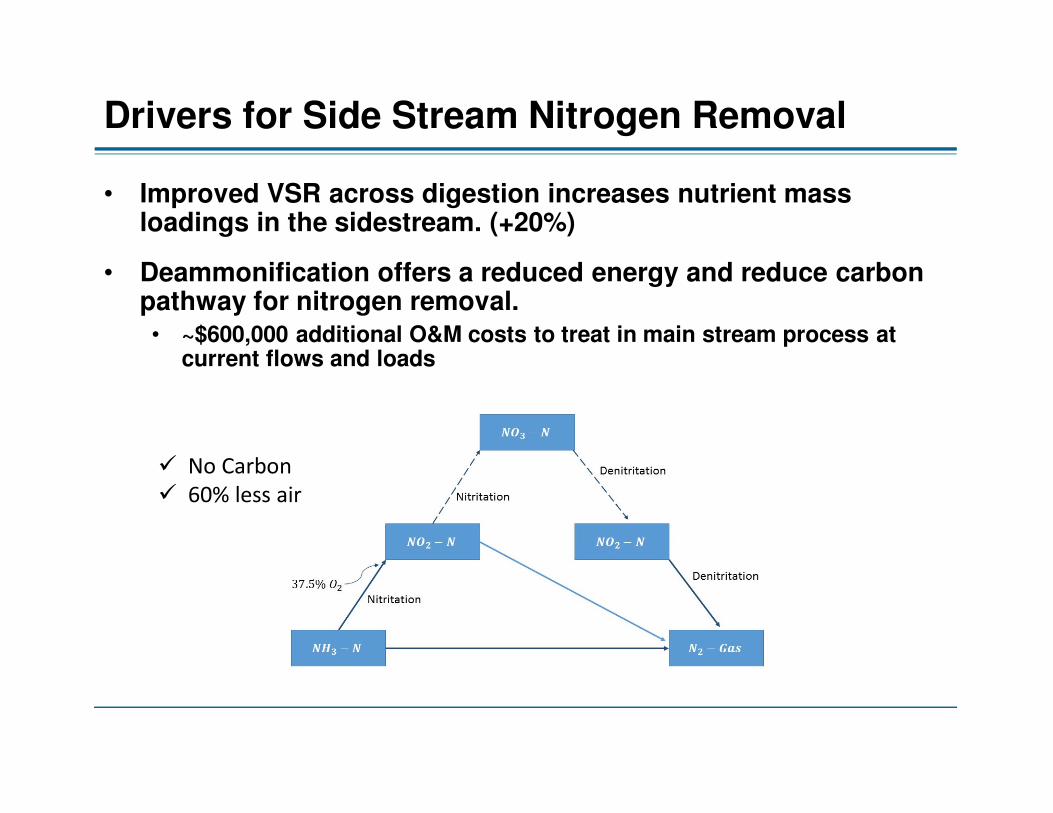
Drivers for Side Stream Nitrogen Removal
• Improved VSR across digestion increases nutrient mass loadings in the sidestream. (+20%)
• Deammonification offers a reduced energy and reduce carbon pathway for nitrogen removal. • ~$600,000 additional O&M costs to treat in main stream process at
current flows and loads
� No Carbon
� 60% less air
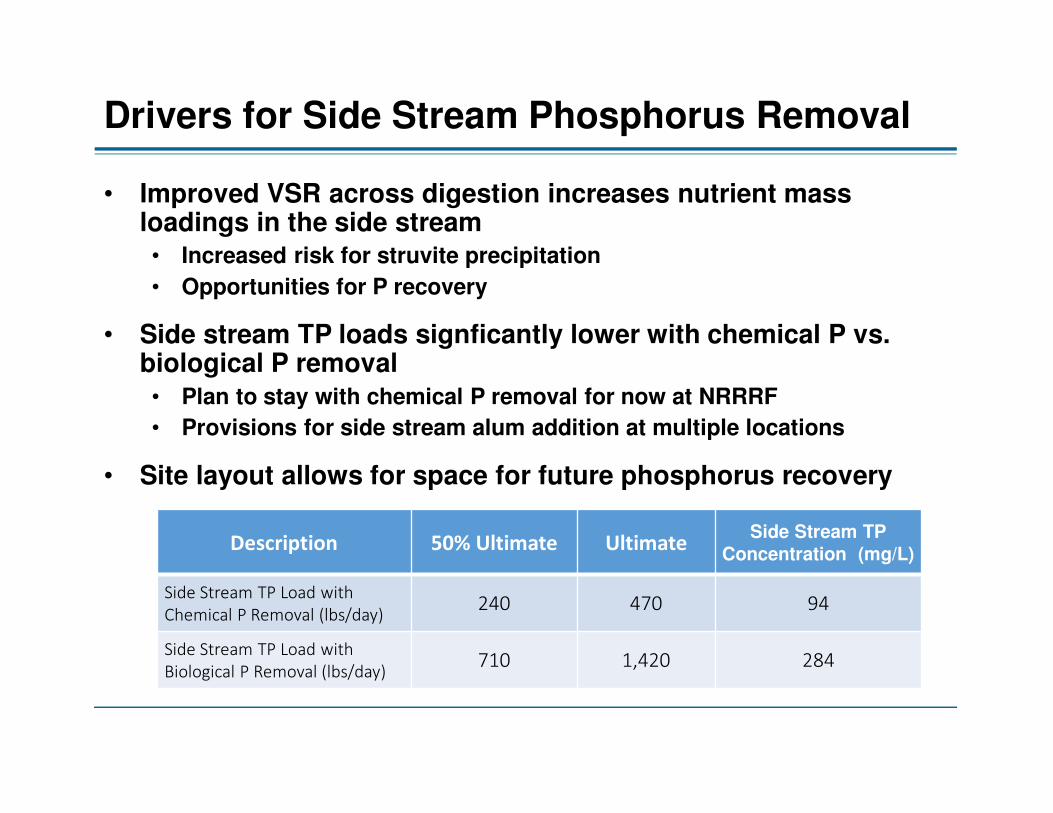
Drivers for Side Stream Phosphorus Removal
• Improved VSR across digestion increases nutrient mass loadings in the side stream • Increased risk for struvite precipitation
• Opportunities for P recovery
• Side stream TP loads signficantly lower with chemical P vs. biological P removal• Plan to stay with chemical P removal for now at NRRRF
• Provisions for side stream alum addition at multiple locations
• Site layout allows for space for future phosphorus recovery
Description 50% Ultimate UltimateSide Stream TP
Concentration (mg/L)
Side Stream TP Load with
Chemical P Removal (lbs/day)240 470 94
Side Stream TP Load with
Biological P Removal (lbs/day)710 1,420 284

Process Considerations for Treating High Strength Filtrate

NRRRF Projected Side Stream Loads
• TKN and NH4 loads from BioWin Modeling, mass balance, and literature
• BOD, COD, CODs, Alkalinity values estimated from literature and other facilities
• Ultimate design based on 90 MGD Design Flow (2040)• Install 1 train designed to treat 50% of ultimate (90 MGD) load now
• 1x Dilution Water – Necessary for effects of high COD in THP Effluent
Description 50% Ultimate Ultimate Diluted Conc (mg/L)
Sidestream Flow (mgd) 0.15 0.30
Dilution Water Flow (mgd) 0.15 0.30
TKN (lb N/day) 3,375 6,750 1,350
NH3 (lb N/day) (85% of TKN) 2,869 5,738 1,150
BOD (lb/day) 125-1,000 250-2,000 50 – 400
COD (lb/day) 7,874 15,748 3,150
CODs (lb/day) 6,750 13,500 2,700
TSS (lb/day) 1,751 3,503 700
Alkalinity (lb/day) 10,125 20,250 4,050

THP Digestate Challenges
• Potential to inhibit AOBs
• Alkalinity and NH3-N balanceHigh TKN
• Potential to Inhibit AOBs
• Increased competition between annamox and heterotrophsHigh COD
• Increased risk for struvite formationHigh TP
• Elevated TSS
• Elevated Polymer
• Diffusion Limitations
Other Potential Challenges

Example Short-Cut Nitrogen Removal “Process Enhancement” Strategies
• Reduce AOB inhibition to high ammonia and COD (Figdore et al, 2011)
Dilute filtrate (≥1:1)
• Improve substrate diffusion (Zhao et al) AOB in suspension; annamox on media (ANITA™ Mox IFAS
configuration)
• Reduce oxygen diffusion limitation (Zhang et al, 2016)
Higher operating DO
• Increase annamox retention (Zhang et al, 2016)
Better annamox selection
• Reduces struvite potential; reduces annamox competition (Remy et al, 2016)
Pretreat filtrate

Proposed Side StreamTreatment Systems for NRRRF

General Process Flow Diagram General Process Flow Diagram General Process Flow Diagram General Process Flow Diagram ––––Side Side Side Side Stream Nitrogen RemovalStream Nitrogen RemovalStream Nitrogen RemovalStream Nitrogen RemovalHeated Dilution
Water for Dewatering
(approximately 1X)
(Solids)
Heated Dilution Water
(if necessary)
To RAS Channel
Side Stream
Influent Pump
Station
Side Stream
Equalization Pump
Station
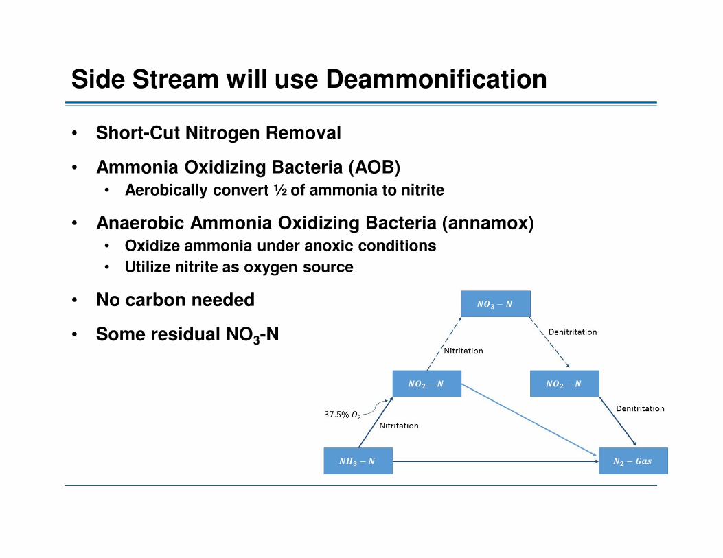
Side Stream will use Deammonification
• Short-Cut Nitrogen Removal
• Ammonia Oxidizing Bacteria (AOB)• Aerobically convert ½ of ammonia to nitrite
• Anaerobic Ammonia Oxidizing Bacteria (annamox)• Oxidize ammonia under anoxic conditions
• Utilize nitrite as oxygen source
• No carbon needed
• Some residual NO3-N

Deammonification Technologies Considered
• Two Recommended from PER• World Water Works conDEA™
• Kruger ANITA™ Mox IFAS
WWW conDEATM Kruger ANITATM Mox IFAS
Reactor configuration Flow Through Flow Through
Biomass characteristic Flocs and granulesBiofilm on media and flocs
(IFAS)
Proprietary retention
strategy
Micro-Screen and Lamella Plate
Settlers
Plastic carriers, screens, and
clarifier
Process Diagram

World Water Works conDEATM
• Continuous flow through process
• Annamox bacteria suspended in granular form
• MicroScreen is use to retain anammox and waste NOB
• Selects for large annamox granules
• 100% of flow can best through screen if clarifier upset
• Messner Panel Aeration (Fine bubble)
• New Lamella clarifier for solids separation
• Strass is running with MicroScreen configuration
• No US installations yet using revised configuration

Kruger ANITA™ Mox IFAS
• Continuous flow through process
• Anammox bacteria colonized on plastic media carriers
• Medium Bubble Aeration System
• Majority of AOBs are in the suspended phase (Zhao et al)
• Clarifier used for solids return, waste from RAS line to maintain design liquid phase SRT
• No US installations of sidestreamIFAS system

ANITA™ Mox – MBBR vs. IFAS Configuration
= 0.5-1.5 mg/L
Biofilm
Flocs (~3 g/L)
Biofilm
Media
Liquid
Nitritation
NH4+
NO2-AOB
Anammox
N2O2
Aerobic
AnaerobicBiofilm
Media
Liquid
Nitritation
AOB
Anammox
AnaerobicMedia
NH4+ NO2
-
O2N2 0.2-0.5 mg/L
Figures courtesy of Veolia (with permission)
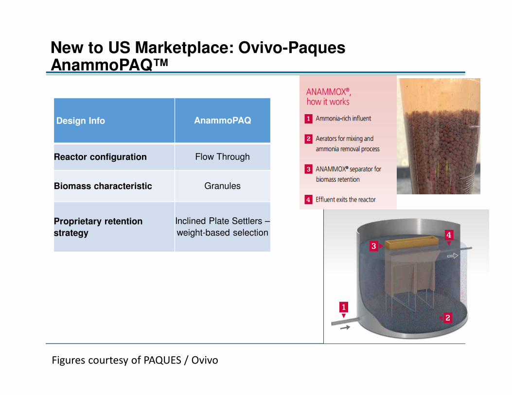
New to US Marketplace: Ovivo-Paques AnammoPAQ™
Design Info AnammoPAQ
Reactor configuration Flow Through
Biomass characteristic Granules
Proprietary retention
strategy
Inclined Plate Settlers –
weight-based selection
Figures courtesy of PAQUES / Ovivo
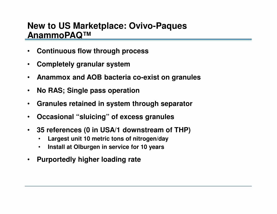
New to US Marketplace: Ovivo-Paques AnammoPAQ™
• Continuous flow through process
• Completely granular system
• Anammox and AOB bacteria co-exist on granules
• No RAS; Single pass operation
• Granules retained in system through separator
• Occasional “sluicing” of excess granules
• 35 references (0 in USA/1 downstream of THP)• Largest unit 10 metric tons of nitrogen/day
• Install at Olburgen in service for 10 years
• Purportedly higher loading rate
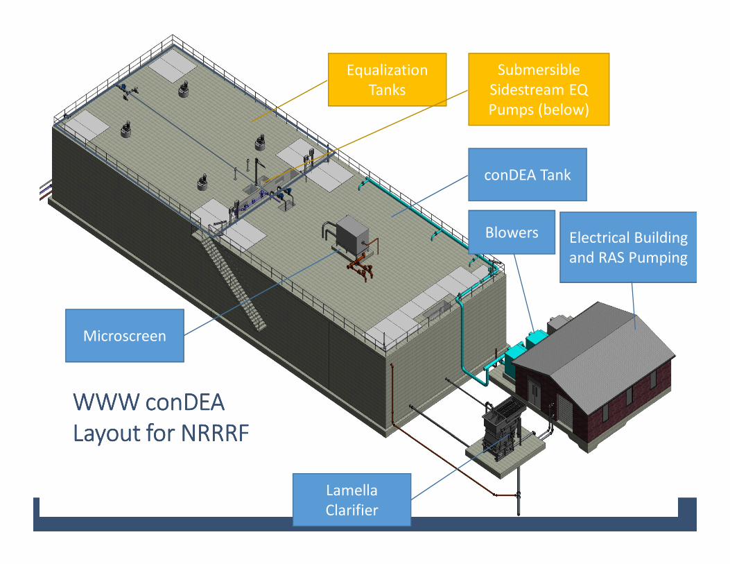
WWW conDEA WWW conDEA WWW conDEA WWW conDEA
Layout for NRRRFLayout for NRRRFLayout for NRRRFLayout for NRRRF
conDEA Tank
Electrical Building
and RAS Pumping
Lamella
Clarifier
Equalization
Tanks
Submersible
Sidestream EQ
Pumps (below)
Blowers
Microscreen

Messner Panels
Effluent weir to
clarifier
EQ Mixing with
Invent Mixers
Concrete supports for
cover and Microscreen
RAS Pumps &
Piping
Submersible Mixers
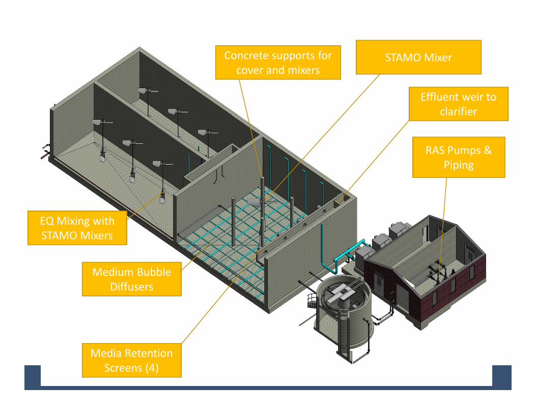
Medium Bubble
Diffusers
Media Retention
Screens (4)
Effluent weir to
clarifier
EQ Mixing with
STAMO Mixers
Concrete supports for
cover and mixers
RAS Pumps &
Piping
STAMO Mixer

LIFT SEE IT Site Visits - Highlights
“The LIFT Scholarship Exchange Experience for Innovation & Technology Program (SEE
IT) is an initiative spearheaded by WE&RF, WEF, and NACWA to provide scholarships
for utility personnel to visit other utilities with innovations of interest and to share
experiences with their peers”
http://www.werf.org/lift/LIFT_SEE_IT.aspx

World Water Works conDEATM , Amersfoort, NL
conDEA reactor
Cyclone separation device
Process Flow diagram
MLSS from Reactor
Clarifier wet well in center of reactor
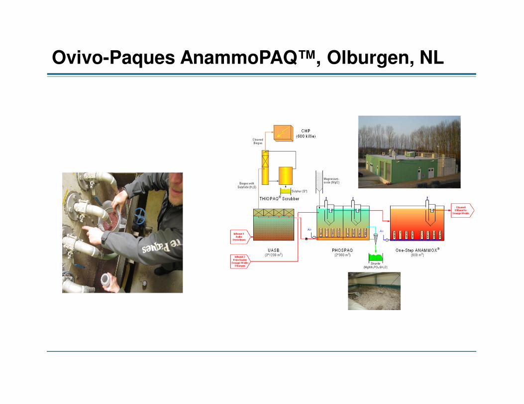
Ovivo-Paques AnammoPAQ™, Olburgen, NL

Veolia ANITA™ Mox IFAS, Boras, Sweden
IFAS System Media retention screens Stamo Mixer Foam Air Lift Pump IFAS Clarifier

Next Steps
• Regroup on LIFT SEE IT Site Visit Findings with Design Team
• Finalize selection criteria (cost and non-cost)
• Develop weighted scoring system
• Obtain updated proposals
• Evaluate using selection criteria and weighted scoring system
• Finalize selection and move forward with final design of side stream treatment system

Thank You!