Lmt 8 Network Architectures
82
Network Architectures 1 AMIT KR. BHARDWAJ, LMTSOM
-
Upload
lakshay187 -
Category
Documents
-
view
261 -
download
1
Transcript of Lmt 8 Network Architectures

Network Architectures
1AMIT KR. BHARDWAJ, LMTSOM

AMIT KR. BHARDWAJ, LMTSOM 2
Objectives
• Compare and contrast media access methods used in network architectures
• Describe the operation of Ethernet• Differentiate between Ethernet standards and
speeds• Explain the four Ethernet frame types and how
they are used

AMIT KR. BHARDWAJ, LMTSOM 3
Objectives (continued)
• Describe the token ring architecture and its components
• Explain the function of Fiber Distributed Data Interface
• Describe other LAN and WAN architectures and their role in today’s networks

AMIT KR. BHARDWAJ, LMTSOM 4
Putting Data on the Cable: Access Methods
• Given that network architectures communicate in a number of different ways, some factors in network communications must be considered– How computers put data on the cable– How they ensure that the data reaches its
destination undamaged

AMIT KR. BHARDWAJ, LMTSOM 5
Function of Access Methods
• The way in which computers attached to a network share the cable must be defined
• A collision results from two or more devices sending a signal along the same channel at the same time– Splitting data in small chunks helps prevent collisions
• Channel access methods specify when computers can access the cable or data channel– Ensure that data reaches destination by preventing
computers from sending messages that might collide– Every computer on a network must use the same
access method

AMIT KR. BHARDWAJ, LMTSOM 6
Major Access Methods
• Channel access is handled at the MAC sublayer of the Data Link layer in the OSI model
• Five major types of channel access– Contention– Switching– Token passing– Demand priority– Polling

AMIT KR. BHARDWAJ, LMTSOM 7
Contention
• In early networks based on contention, computers sent data whenever they had data to send
• As networks grow, outgoing messages collide more frequently, must be sent again, and then collide again
• To organize contention-based networks, two carrier access methods were created– CSMA/CD– CSMA/CA

AMIT KR. BHARDWAJ, LMTSOM 8
Carrier Sense Multiple Access with Collision Detection (CSMA/CD)

AMIT KR. BHARDWAJ, LMTSOM 9
Carrier Sense Multiple Access with Collision Avoidance (CSMA/CA)
• When the computer senses that no other computer is using the network, it signals its intent to transmit – Other computers with data to send must wait when they
receive the “intent-to-transmit” signal and send their “intent-to-transmit” only when channel is free
• The overhead created by intent-to-transmit packets reduces network speed significantly
• Used in wireless LANs with an access point– Wireless NIC tells access point its intents to transmit– Access point hears transmissions from all devices, so it can
determine whether it’s okay to transmit

AMIT KR. BHARDWAJ, LMTSOM 10
Switching
• Switching: nodes are interconnected through a a switch, which controls access to the media– Contention occurs only when multiple senders ask to
reach the same receiver simultaneously or when the simultaneous transmission requests exceed the switch’s capability to handle multiple connections
• Advantages: fairer, centralized management (enables QoS), switch can have connection ports that operate at different speeds
• Disadvantage: higher cost

AMIT KR. BHARDWAJ, LMTSOM 11
Token Passing

AMIT KR. BHARDWAJ, LMTSOM 12
Demand Priority
• Demand priority: channel access method used solely by the 100VG-AnyLAN 100 Mbps Ethernet standard (IEEE 802.12)– 100VG-AnyLAN runs on a star bus topology– Intelligent hubs control access to the network
• Hub searches all connections in a round-robin fashion• When an end node has data to send, it transmits a demand
signal to the hub• The hub then sends an acknowledgement that the computer
can start transmitting its data– The major disadvantage of demand priority is price

AMIT KR. BHARDWAJ, LMTSOM 13
Polling

AMIT KR. BHARDWAJ, LMTSOM 14
Choosing an Access Method

AMIT KR. BHARDWAJ, LMTSOM 15
Choosing an Access Method (continued)

AMIT KR. BHARDWAJ, LMTSOM 16
Choosing an Access Method (continued)

AMIT KR. BHARDWAJ, LMTSOM 17
The Ethernet Architecture• 1960s and 1970s: many organizations worked on
methods to connect computers and share data– E.g., the ALOHA network at the University of Hawaii– 1972: Robert Metcalf and David Boggs, from Xerox’s
PARC, developed an early version of Ethernet• 1975: PARC released first commercial version (3 Mbps, up to
100 computers, max. 1 km of total cable)• DIX developed standard based on Xerox’s
Ethernet (10 Mbps)• 1990: IEEE defined the 802.3 specification
– Defines how Ethernet networks operate at layers 1-2

AMIT KR. BHARDWAJ, LMTSOM 18
Overview of Ethernet
• Ethernet is the most popular network architecture – Advantages: easy to install, scalable, broad media
support, and low cost– Supported transmission speeds: 10 Mbps to 10 Gbps– Uses the NIC’s MAC address to address frames– Ethernet variations are compatible with one another
• Basic operation and frame formatting is the same• Cabling, speed of transmission, and method by which bits
are encoded on the medium differ

AMIT KR. BHARDWAJ, LMTSOM 19
Ethernet Operation
• Ethernet is a best-effort delivery system– It works at the Data Link layer of the OSI model
• Relies on the upper-layer protocols to ensure reliable delivery of data
• Understanding the following concepts is important:– How Ethernet accesses network media– Collisions and collision domains– How Ethernet handles errors– Half-duplex and full-duplex communications

AMIT KR. BHARDWAJ, LMTSOM 20
Accessing Network Media
• Ethernet uses CSMA/CD in a shared-media environment (a logical bus)– Ethernet device listens for a signal or carrier
(carrier sense) on the medium first– If no signal is present, no other device is using the
medium, so a frame can be sent– Ethernet devices have circuitry that detects
collisions and automatically resends the frame that was involved in the collision
AMIT KR. BHARDWAJ, LMTSOM 21
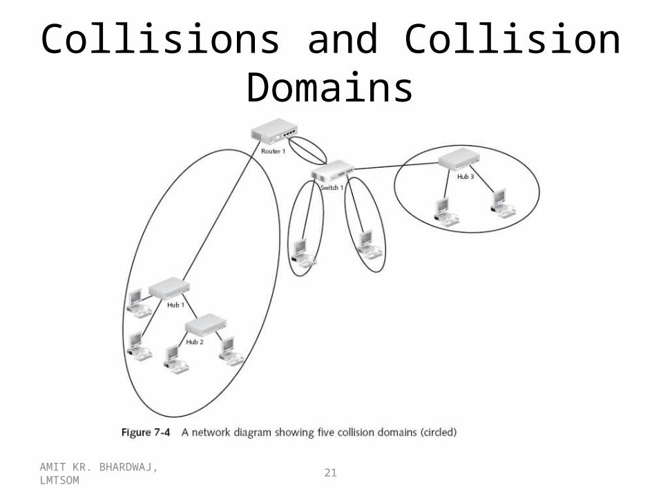
Collisions and Collision Domains

AMIT KR. BHARDWAJ, LMTSOM 22
Ethernet Error Handling
• Collisions are the only type of error for which Ethernet automatically attempts to resend the data
• Errors can occur when data is altered in medium – Usually caused by noise or faulty media connections– When the destination computer receives a frame, the CRC
is recalculated and compared against the CRC value in the FCS
– If values match, the data is assumed to be okay– If values don’t match, the data was corrupted
• Destination computer discards the frame• No notice is given to the sender

AMIT KR. BHARDWAJ, LMTSOM 23
Half-Duplex Versus Full-Duplex Communications
• When half-duplex communication is used with Ethernet, CSMA/CD must also be used
• When using a switched topology, a computer can send and receive data simultaneously (full-duplex communication)– The collision detection circuitry is turned off
because collisions aren’t possible– Results in a considerable performance advantage

AMIT KR. BHARDWAJ, LMTSOM 24
Ethernet Standards
• Each Ethernet variation is associated with an IEEE standard
• The following sections discuss many of the standards, some of which are obsolete or had limited use
• Keep in mind that Ethernet over UTP cabling has been the dominant technology since the early 1990s, and will likely to continue to be for the foreseeable future

AMIT KR. BHARDWAJ, LMTSOM 25
100 Mbps IEEE Standards• The most widely accepted Ethernet standard
today is 100BaseT, which is also called fast Ethernet– The current IEEE standard for 100BaseT is 802.3u
• Subcategories:– 100BaseTX: Two-pair Category 5 or higher UTP– 100BaseT4: Four-pair Category 3 or higher UTP– 100BaseFX: Two-strand fiber-optic cable
– Because of its widespread use, the cable and equipment in fast Ethernet are inexpensive
– Architecture of choice for all but heavily used servers and multimedia applications

AMIT KR. BHARDWAJ, LMTSOM 26
100BaseTX
• 100BaseTX is the standard that’s usually in mind when discussing 100 Mbps Ethernet
• Requires two of the four pairs bundled in a Category 5 twisted-pair cable
• Although three cable types are available for 100BaseT, 100BaseTX is the most widely accepted– Generally called fast Ethernet

AMIT KR. BHARDWAJ, LMTSOM 27
100BaseT4
• 100BaseT4 Ethernet uses all four pairs of wires bundled in a UTP cable
• Advantage: capability to run over Category 3 cable– One of the biggest expenses of building a network
is cable installation, so many organizations with Category 3 cabling chose to get the higher speed with the existing cable plant by using 100BaseT4 instead of 100BaseTX

AMIT KR. BHARDWAJ, LMTSOM 28
100BaseFX
• 100BaseFX uses two strands of fiber-optic cable
– Advantages:• Impervious to electrical noise and electronic eavesdropping• Can span much greater distances between devices
– Disadvantage: far more expensive than twisted-pair– Rarely used as a complete 100BaseTX replacement
• Used as backbone cabling between hubs or switches and to connect wiring closets between floors or buildings
• Connect client or server computers to the network when immunity to noise and eavesdropping is required

AMIT KR. BHARDWAJ, LMTSOM 29
100BaseT Design Considerations

AMIT KR. BHARDWAJ, LMTSOM 30
100BaseT Design Considerations (continued)

AMIT KR. BHARDWAJ, LMTSOM 31
10 Mbps IEEE Standards
• Four major implementations of 10 Mbps Ethernet– 10Base5: Ethernet using thicknet coaxial cable– 10Base2: Ethernet using thinnet coaxial cable– 10BaseT: Ethernet over UTP cable– 10BaseF: Ethernet over fiber-optic cable
• Of these 10 Mbps standards, only 10BaseT and 10BaseF are seen today
• 10Base2 and 10Base5 are essentially obsolete

AMIT KR. BHARDWAJ, LMTSOM 32
10BaseT

AMIT KR. BHARDWAJ, LMTSOM 33
10BaseF

AMIT KR. BHARDWAJ, LMTSOM 34
Gigabit Ethernet: IEEE 802.3ab and 802.3z Standards
• Gigabit Ethernet implementations– 802.3z-1998 covers 1000BaseX specifications,
including the L (long wavelength laser/fiber-optic), S (short wavelength laser/fiber-optic), and C (copper jumper cables)
– 802.3ab-1999 covers 1000BaseT specifications, which require four pairs of 100 ohm Category 5 or higher cable

AMIT KR. BHARDWAJ, LMTSOM 35
What’s Next for Ethernet?
• Implementations of 40 Gbps Ethernet are underway• Ethernet could increase tenfold every 4-6 years
– 100 Gbps Ethernet available by 2006 to 2008, terabit Ethernet by 2011, and 10 terabit Ethernet by 2015
• In October 2005, Lucent Technologies demonstrated for the first time the transmission of Ethernet over fiber-optic cable at 100 Gbps– It will be able to transfer data across the city faster than
today’s CPUs can transfer data to memory– This level of speed has major implications for the
entertainment industry and many other areas

AMIT KR. BHARDWAJ, LMTSOM 36
Ethernet Frame Types
• Ethernet supports four non-compatible frame types– Ethernet 802.3: used by IPX/SPX on Novell NetWare
2.x and 3.x networks– Ethernet 802.2: used by IPX/SPX on Novell NetWare
3.12 and 4.x networks• Supported by default in Microsoft NWLink
– Ethernet SNAP: used in EtherTalk and mainframes– Ethernet II is used by TCP/IP
• All Ethernet frame types support a packet size between 64 and 1518 bytes, and can be used by all network architectures mentioned previously

AMIT KR. BHARDWAJ, LMTSOM 37
Ethernet 802.3

AMIT KR. BHARDWAJ, LMTSOM 38
Ethernet 802.2
• Ethernet 802.2 frames comply completely with the Ethernet 802.3 standard
• The IEEE 802.2 group didn’t address Ethernet, only the LLC sublayer of the OSI model’s layer 2– Since Novell had already decided to use the term
Ethernet 802.3 to describe Ethernet raw, it’s generally accepted that Ethernet 802.2 means a fully 802.3- and 802.2-compliant Ethernet frame
• Ethernet 802.2 frames contain similar fields to 802.3, with three additional LLC fields

AMIT KR. BHARDWAJ, LMTSOM 39
Ethernet SNAP
• Ethernet SubNetwork Address Protocol (SNAP) is generally used on the AppleTalk Phase 2
• It contains enhancements to the 802.2 frame, including a protocol type field, which indicates the network protocol used in the frame’s data section

AMIT KR. BHARDWAJ, LMTSOM 40
Ethernet II

AMIT KR. BHARDWAJ, LMTSOM 41
Wireless Ethernet: IEEE 802.11b, a, and g
• AP serves as the center of a star topology network• Stations can’t send and receive at the same time
– CSMA/CA is used instead of CSMA/CD• 802.11b/a/g use handshaking before transmission
– Station sends AP an RTS and it responds with CTS• Standards define a maximum transmission rate, but
speeds might be dropped to increase reliability• No fixed segment length
– Maximum of 300 feet without obstructions• Can be extended with large, high-quality antennas

AMIT KR. BHARDWAJ, LMTSOM 42
The Token Ring Architecture
AMIT KR. BHARDWAJ, LMTSOM 43
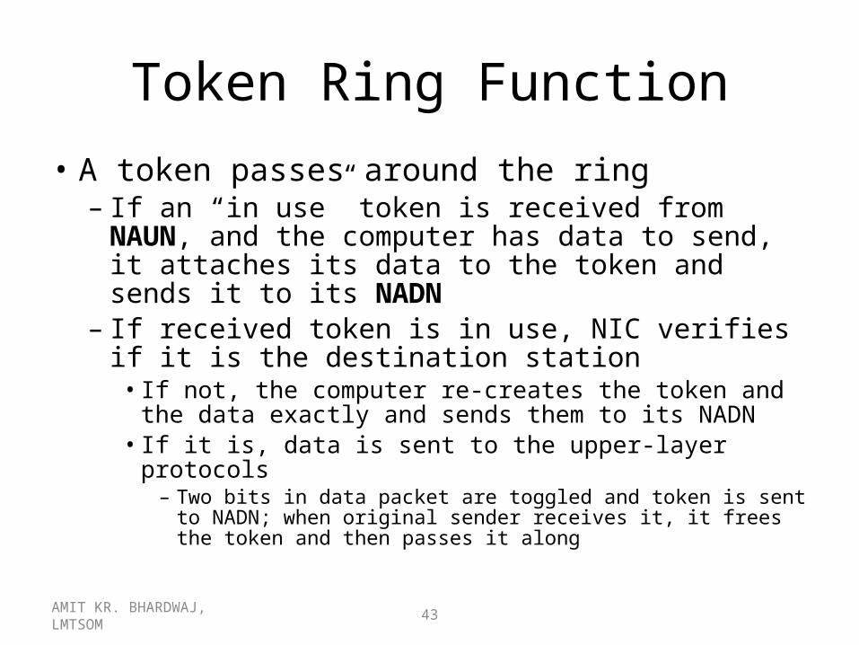
Token Ring Function
• A token passes around the ring– If an “in use” token is received from NAUN, and
the computer has data to send, it attaches its data to the token and sends it to its NADN
– If received token is in use, NIC verifies if it is the destination station
• If not, the computer re-creates the token and the data exactly and sends them to its NADN
• If it is, data is sent to the upper-layer protocols– Two bits in data packet are toggled and token is sent to
NADN; when original sender receives it, it frees the token and then passes it along

AMIT KR. BHARDWAJ, LMTSOM 44
Beaconing

AMIT KR. BHARDWAJ, LMTSOM 45
Hardware Components• A hub can be a multistation access unit (MSAU)
or smart multistation access unit (SMAU)• IBM’s token ring implementation is the most
popular adaptation of the IEEE 802.5 standard– Minor variations but very similar to IEEE specs
• IBM equipment is most often used– 8228 MSAU has 10 connection ports, eight of which
can be used for connecting computers– The RO port on one hub connects to RI port on the
next hub, and so on, to form a ring among the hubs• IBM allows connecting 33 hubs

AMIT KR. BHARDWAJ, LMTSOM 46
Cabling in a Token Ring Environment
AMIT KR. BHARDWAJ, LMTSOM 47
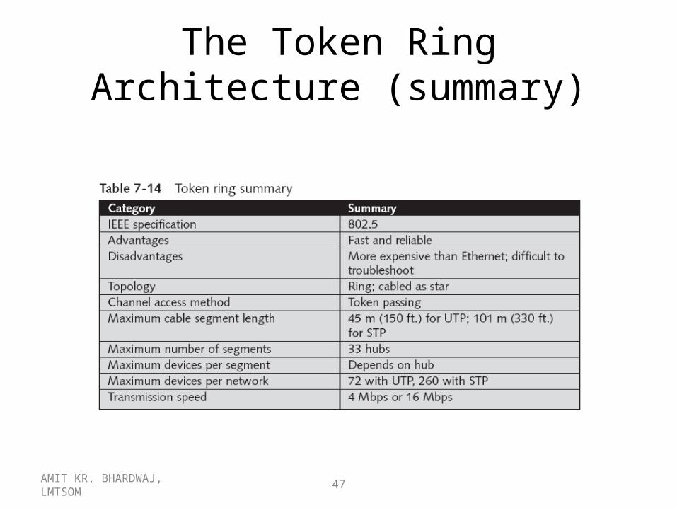
The Token Ring Architecture (summary)
AMIT KR. BHARDWAJ, LMTSOM 48
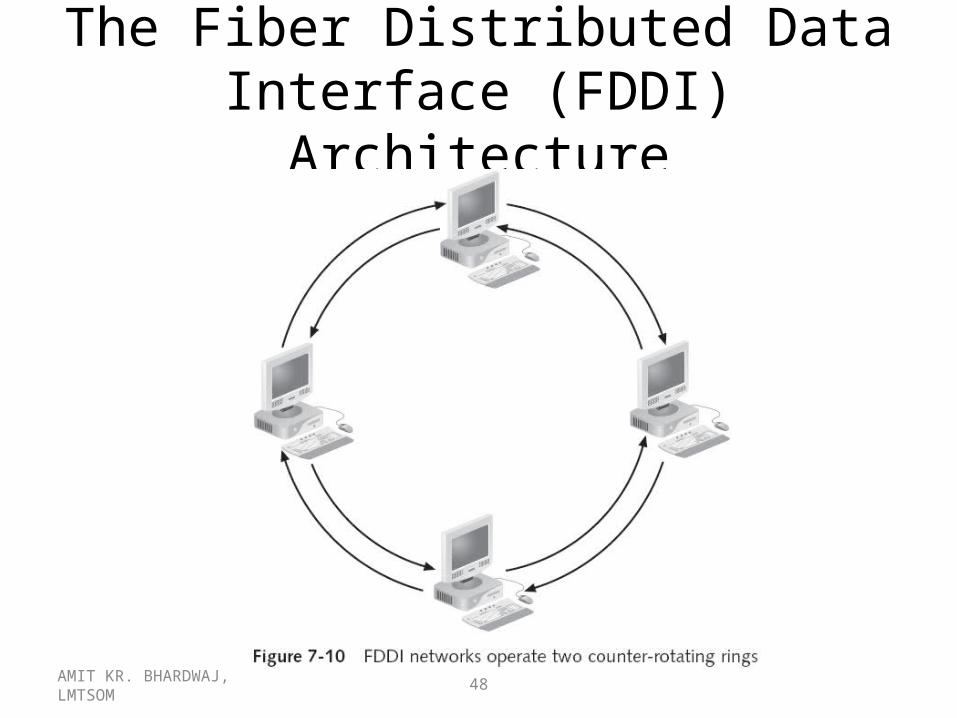
The Fiber Distributed Data Interface (FDDI) Architecture
AMIT KR. BHARDWAJ, LMTSOM 49
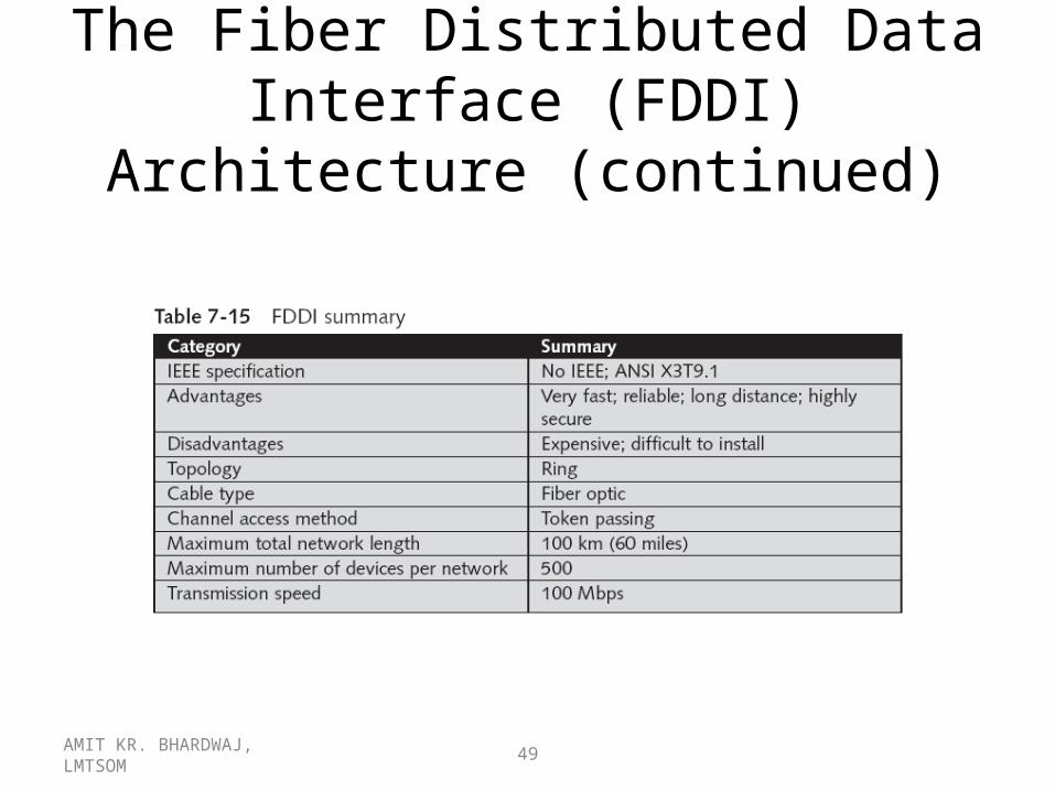
The Fiber Distributed Data Interface (FDDI) Architecture (continued)

AMIT KR. BHARDWAJ, LMTSOM 50
Networking Alternatives
• Many other network architectures are available• Some are good for specialized applications, and
others are emerging as new standards• Topics
– Broadband technologies (cable modem and DSL)– Broadcast technologies– ATM– ATM and SONET Signaling Rates– High Performance Parallel Interface (HIPPI)

AMIT KR. BHARDWAJ, LMTSOM 51
Broadband Technologies
• Baseband systems use a digital encoding scheme at a single fixed frequency
• Broadband systems use analog techniques to encode information across a continuous range of values– Signals move across the medium in the form of
continuous electromagnetic or optical waves– Data flows one way only, so two channels are
necessary for computers to send and receive data– E.g., cable TV

AMIT KR. BHARDWAJ, LMTSOM 52
Cable Modem Technology

AMIT KR. BHARDWAJ, LMTSOM 53
Digital Subscriber Line (DSL)
• Competes with cable modem for Internet access– Broadband technology that uses existing phone lines
to carry voice and data simultaneously– Most prominent variation for home Internet access is
Asymmetric DSL (ADSL)• Splits phone line in two ranges: Frequencies below 4 KHz are
used for voice transmission, and frequencies above 4 KHz are used to transmit data
• Typical connection speeds for downloading data range from 256 Kbps to 8 Mbps; upload speeds are in the range of 16 Kbps to 640 Kbps

AMIT KR. BHARDWAJ, LMTSOM 54
Broadcast Technologies• By definition: one-way transmissions
– This changed in Internet access by satellite television systems
• Work on the principle that most traffic a user generates is to receive files, text, and graphics– The average user’s computer sends very little traffic– User connects to service provider through a modem– Service provider sends data by satellite to the user’s
home at speeds up to 400 Kbps– E.g., service offered by DirectTV, through its DirectPC
add-on products

ISDN
•Integrated Services Digital Network
•A digital telephone service that provides fast, accurate data transmission over existing copper telephone wiring
•The way fast way to go online

What Do I Use It For?
• ISDN offers the speed and quality that previously was only available to people who bought expensive, point-to-point digital leased lines. Combined with its flexibility as a dial-up service, ISDN has become the service of choice for many communications applications.

Why Should I Use ISDN
• Internet becomes more and more information-intensive with graphics, sound, video and multimedia
• By combining your two B-channels you have access to up to 128 kbps -- more than four times as fast as a 28.8 kbps modem on a standard phone line
• More efficient and economical• ISDN brings increased capabilities, reduced costs and
improved productivity to organizations both large and small.

Popular ISDN applications include:
• Internet access
• Telecommuting/remote access to corporate computing
• Video conferencing
• Small and home office data networking

ISDN CHANNELS
• B-channel • The Bearer ("B") channel is a 64 kbps channel which can be
used for voice, video, data, or multimedia calls. B-channels can be aggregated together for even higher bandwidth applications.
• D-channel • The Delta ("D") channel can be either a 16 kbps or 64 kbps
channel used primarily for communications (or "signaling") between switching equipment in the ISDN network and the ISDN equipment at your site.

Two Pre-Defined Configurations
• Basic Rate Interface (BRI)
• BRI is the ISDN service most people use to connect to the Internet
• Two 64 kbps B-channels and one 16 kbps D-channel over a standard phone line
• Often called "2B+D" • A single BRI line can support up to three calls at the same time • Two voice, fax or data "conversations," and one packet
switched data "conversation" can take place at the same time.

Primary Rate Interface (PRI)
• Used primarily by large organizations with intensive
communications needs • Supports 64 kbps B-channels • One 64 kbps D-channel • Often called 23B+D in usa• 30B+D india• BISDN – EMPLOYS IN ATM

Typical ISDN Configuration


Network Termination Device 1 (NT1)
• The NT1 is a simple device that serves as an interface between the ISDN BRI line and your other ISDN equipment.
• It converts the physical wiring interface delivered by PSTN to the wiring interface needed by your ISDN equipment
• Also provides a testing point for troubleshooting.

U-Interface
l The U-interface is the 2-wire interface your phone company delivers for connection to the NT1
S/T Interface The S/T-interface is the 4-wire interface between the NT1 and the ISDN networking equipment such as an ISDN TA or router

ATM NETWORKS

Origins of ATM
Existing telecommunication network(s) were/are very specialized.
They have Following disadvantages:• Service Dependence• Inflexibility• Inefficiency• Costs

Issues with current available transfer modes
• Circuit Switching: Circuit switching is inflexible since once the duration of a time slot is fixed the bit rate is fixed.
• Packet Switching: As the error rate increases more and more of the traffic is taken up with retransmission activities, Also due to its high degree of processing it is not suitable for high bit rates and real time services

Asynchronous Transfer Mode (ATM)
Asynchronous Transfer Mode is a digital technique forhigh speed switching.• The unit of multiplexing and switching is a cell which
comprises a short fixed length information packet with a fixed length header to carry signaling information.
• By offering access at the cell level, information from many sources with widely differing activity patterns and transmission rates can be interleaved on a single transmission link.
• ATM takes advantage of the excellent transmission characteristics of modern media such as optical fiber, which provide an extremely low bit error rate. No loss of cells.

Benefits of ATM• Scalability: ATM is a scalable technology. The ATM standard
describes a 53 byte cell format, but does not dictate bit rates, framing or physical bearers. Thus manydifferent systems such as LANs, public networks, MANs can use the same format.
• Transparency: ATM is application transparent. The cell size is a compromise between the long frames generated by data applications and the short repetitive needs of voice. It is also suitable for isochronous services such as video. ATM will also allow free mixture of data and voice or video within the same application.


Benefits of ATM• Granularity: ATM allows the network to be tailored to the
application rather than forcing applications to fit the network. Todays TDM network has trouble dealing with anything that does not fit the limited granularity of the digital hierarchy. Thus with TDM if application requires more than 155 Mbit/s but less than 622 Mbit/s it is necessary to buy the 622 Mbit/s service.
• High speed switching: ATMs short fixed cell size points the way to the realisation of high speed switching extendible in size and speed.
• Network flexibility: -virtual private networks for data; - provides self routing digital cross-connects for network reconfigurable; integration to LANs, MANs through common formats.

ATM Cell Structure

ATM Cell Structure ..

ATM Cell Structure…• GFC: generic flow control field; used to control flow
across user-network interface.• VPI/VCI: Virtual path/virtual channel identifier-ATM
address.• PT: payload type; type of information carried by the
cell.• CLP: cell loss priority; set by user; priority for
discarding under congested conditions.• HEC: header error control field: error correcting
code designed to detect multiple header errors and correct single bit errors.

Characteristics of ATM• No error protection or flow control on a link by link
basis. In ATM no dynamic actions are taken against packet loss.
• Operates in a connection oriented mode. Before information is transferred to the network the network resources must be reserved.
• ATM assumes one and only one defined path exists through the network for transport of cells during a call. Therefore cells will arrive in sequence since they all travel the same path (sequence integrity).
• Reduced header functionality. Reduces processing delays.
• Small information field. Reduced internal buffers and less jitters and delays.

Classes of Service of ATMThe ATM Adaption layer (AAL) is used to describe to thenetwork the type of service that is being carried.• Class A (AAL1): data streams with constant bit rate, running over
established connections. Telephony, Megastream, Kilostream, Nx64 kbit/s
• Class B (AAL2): similar to A but instead of being fixedbit rate they send bursts of data; e.g. compressed video
• Class C: data messages on established connections.Inherently variable bit rate. E.g. X25 and Frame Relay
• Class D: Connectionless datagrams where a packet is sentinto a network and contains its own destination address.e.g. LANs, WANs

AMIT KR. BHARDWAJ, LMTSOM 78
Asynchronous Transfer Mode (ATM)
• High-speed network technology for LANs and WANs– Connection-oriented switches
• Dedicated circuits are set up before communicating– Data travels in fixed-size 53-byte cells (5 byte-header)
• Enables ATM to work at extremely high speeds– Quick switching– Predictable traffic flow
• Enables ATM to guarantee QoS– Used quite heavily for the backbone and
infrastructure in large communications companies– LAN emulation (LANE) required for LAN applications

AMIT KR. BHARDWAJ, LMTSOM 79
ATM and SONET Signaling Rates
AMIT KR. BHARDWAJ, LMTSOM 80
High Performance Parallel Interface (HIPPI)
• HIPPI (late 1980s): high-speed interface developed for supercomputers and high-end workstations– Serial HIPPI is a fiber-optic version that uses point-to-
point optical links for bandwidth up to 800 Mbps• In early 1990s, it was used as a network backbone and for
interconnecting supercomputers– With the advent of Gigabit Ethernet, interest in HIPPI as a LAN
backbone decreased– HIPPI-6400 (1998): up to 6.4 Gbps transfer rates
• Known as Gigabyte System Network (GSN)– HIPPI and GSN are now exotic networking products
and aren’t often found in typical corporate networks

AMIT KR. BHARDWAJ, LMTSOM 81
Summary• Cable access methods determine how a network
architecture gains access to the network medium• A network architecture defines how data is
placed, transmitted, and at what speed, and how problems in the network are handled
• DIX introduced Ethernet, which later became the IEEE 802.3 standard, transmitting data at 10 Mbps– Standards for 10Mbps, 100Mbps, 1000Mbps (Gigabit),
and 10G indicate the supported network mediums• 10 Gigabit Ethernet runs only over fiber-optic cable and only
in full-duplex mode

AMIT KR. BHARDWAJ, LMTSOM 82
Summary (continued)
• Token ring networks are reliable, fast, and efficient– Capable of transmitting at 4 Mbps or 16 Mbps
• Macintosh computers use AppleTalk to communicate
• FDDI is an extremely reliable, fast network architecture that uses dual counter-rotating rings
• Cable modem technology delivers high-speed Internet access to homes and businesses
• ATM, a high-speed network technology designed both for LANs and WANs, uses connection-oriented switches