LK Series · APEM 3 LK series Keylock Switches MODEL STRUCTURE OPTIONS Panel cut-out Ø19 (0.755) +...
3
APEM www.apem.com 1 LK series Keylock Switches Distinctive features and specifications ELECTRICAL SPECIFICATIONS GENERAL SPECIFICATIONS MATERIALS AGENCY APPROVALS The company reserves the right to change specifications without notice. LK_U1807US Single and double pole options Up to four positions Momentary and maintained switching Multiple key pull position options 45° or 90° indexing • Lock housing : Zinc alloy die casted, nickel plated • Cylinder : 4 disc tumbler, zinc alloy die casted, nickel plated • Keys : 2 single bitted keys, brass nickel plated • Contacts & terminals : Gold plated copper alloy • Body : Glass filled polyester • Contact rating : 4A at 125 VAC or 28VDC, 2A at 250 VAC • Contact resistance : ≤ 10 mΩ • Insulation resistance : ≥109 MΩ • Dielectric strength : 1000 V RMS minimum at sea level • Electrical life : 6000 cycles at full load File E83438 • Mechanical life : 6000 cycles at full load. • Operating temperature range : -30°C to +85°C Dimensions : first dimensions are in mm while inches are shown in brackets. Mounting accessories : Standard hardware supplied : 1 nut. For spare keys please contact APEM. Packaging unit : 25 Refer to the following pages for further information.
Transcript of LK Series · APEM 3 LK series Keylock Switches MODEL STRUCTURE OPTIONS Panel cut-out Ø19 (0.755) +...
APEM www.apem.com 1
LK seriesKeylock Switches
Distinctive features and specifications
ELECTRICAL SPECIFICATIONS GENERAL SPECIFICATIONS
MATERIALS AGENCY APPROVALS
The company reserves the right to change specifications without notice.
LK_U1807US
Single and double pole options
Up to four positions
Momentary and maintained switching
Multiple key pull position options
45° or 90° indexing
• Lock housing : Zinc alloy die casted, nickel plated• Cylinder : 4 disc tumbler, zinc alloy die casted, nickel plated• Keys : 2 single bitted keys, brass nickel plated• Contacts & terminals : Gold plated copper alloy• Body : Glass filled polyester
• Contact rating : 4A at 125 VAC or 28VDC, 2A at 250 VAC• Contact resistance : ≤ 10 mΩ• Insulation resistance : ≥109 MΩ• Dielectric strength : 1000 V RMS minimum at sea level• Electrical life : 6000 cycles at full load
File E83438
• Mechanical life : 6000 cycles at full load.• Operating temperature range : -30°C to +85°C
Dimensions : first dimensions are in mm while inches are shown in brackets.
Mounting accessories : Standard hardware supplied : 1 nut. For spare keys please contact APEM.
Packaging unit : 25
Refer to the following pages for further information.

2 APEMwww.apem.com
LK seriesKeylock SwitchesOverview
Key typeSERIES FinishFunction
N Nickel platedG Black
126 Std
Hardware
3 Nut (std)4 Clip
6 Maintained5 Momentary
No ofPoles
No ofPoles
LockConfiguration
LockConfiguration
Indexing
Indexing
Key PullPosition
Key PullPosition
Key options
N Nickel Key (std)M Overmoulded
BLK
A SP
B (std) DP
C SP
D (std) DP
E SP
F (std) DP
G SP
H (std) DP
7 SP
J (std) DP
N SP
8 (std) DP
P SP
Q (std) DP
R SP
S (std) DP
9 DP
G SP
A (std) SP
B DP
E (std) SP
F DP
7 (std) SP
J DP
45°
45°
45°
45°
45°
45°
45°
45°
45°
45°/90°
1
1
1
1
1
1
1
1
1
1
1
1
1
Pos. 1 Pos. 2 Pos. 3 Pos. 4Terminals Connected
Pos. 1 Pos. 2 Pos. 3 Pos. 4Terminals Connected
8-1 1-2 2-3
8-1, 4-5 1-2, 5-6 2-3, 6-7
8-1 1-2 2-3
8-1, 4-5 1-2, 5-6 2-3, 6-7
8-1 1-2 2-3
8-1 1-2 2-3 3-4
8-1 1-2 7-8
8-1, 4-5 1-2, 5-6 2-3, 6-7
8-1, 4-5 1-2, 5-6 7-8, 3-4
8-1 1-2 7-8
8-1 1-3
8-1 1-3
8-1, 4-5 1-2, 5-6 7-8, 3-4
8-1 1-2 7-8
8-1, 4-5 1-2, 5-6 7-8, 3-4
8-1 1-2 7-8
7-1 1-2 6-7
8-1, 4-5 1-2, 5-6 7-8, 3-4
8-1, 4-5 1-3, 5-7
8-1, 4-5 1-3, 5-7
8-1 1-3
8-1, 4-5 1-3, 5-7
8-1 1-2
8-1, 4-5 1-2, 5-6
2
2
2
2
2
2
2
2
2
2
2
2
3
3
3
3
3
1
3
1 & 3
1 & 3
1 & 2
1
1
1
1
1
2
1, 2 & 3
1, 2, 3 & 4
Maintainedfunction
Momentaryfunction
90°
90°
90°
3
3
3
3 2
4
126
Key pull position
Detent positions
Momentary positions
APEM www.apem.com 3
LK seriesKeylock Switches
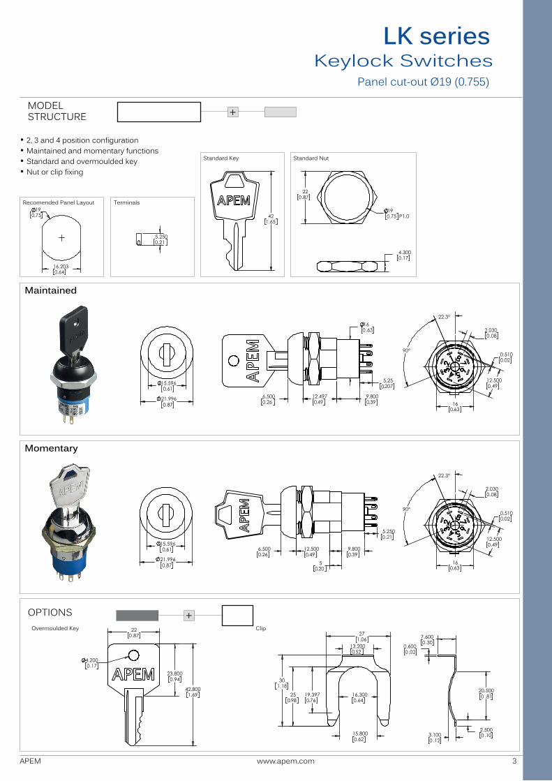
MODELSTRUCTURE
OPTIONS
Panel cut-out Ø19 (0.755)
+
Maintained
Momentary
Terminals
• 2, 3 and 4 position configuration• Maintained and momentary functions• Standard and overmoulded key• Nut or clip fixing
+
Recomended Panel Layout
Standard Key Standard Nut
Overmoulded Key Clip
6.500.26
12.500.49
5
9.800.39
5.250.21
0 0 0
0
.20 0
6.500.26
12.497.49
9.800.39
5.25.207
16.63
0
0
0
0021.996.87
15.596.610
0
21.996.87
15.596.610
0
42
1.65
22.87
19.75 P1.0
4.300.17
0
0
0
5.250.210
19.75
16.203
.64
0
0
22.3°
16.63
12.500.490
0
90° 0.510.02
2.030.08
0
0
22.3°
16.63
12.500.490
0
90° 0.510.02
2.030.08
0
0
0
27
1.06
13.200
.52
16.300.64
30
1.18
19.397
.76
15.800
.62
25.98
0.600
.02
7.600.30
20.500
.81
2.500
.10 3.100
.12
0
0
0
0
0
0
0
0
0
42.8001.69
23.800
.94
22.87
4.200.17
0
0
0