LK 400/500 SERIES LINEAR AMPLIFIERS
45
AMP SUPPLY CO. LK 400/500 SERIES LINEAR AMPLIFIERS OWNER'S MANUAL Amp Supply Co. 6307 Chapel Hill Rd. Raleigh, NC 27607
Transcript of LK 400/500 SERIES LINEAR AMPLIFIERS

AMP SUPPLY CO.
LK 400/500 SERIES LINEAR AMPLIFIERS
OWNER'S MANUAL
Amp Supply Co. 6307 Chapel Hill Rd. Raleigh, NC 27607
Table of C ontents
Section T it le Page
1.0 Introduction 11.1 Product Description 11.2 Specifica tions 21.2.1 Common Specifications 21.2.2 Unique Specifications 41.3 Front Panel Features 61.4 Rear Apron Features 7
2.0 Ins ta lla t ion 92.1 Introduction 92.2 Unpacking 92.3 Warranty Card 92.4 Ins ta lla t ion 92.4.1 Tube Installation 1 02.5 Amplifier Placement 1 02.6 Power Requirements 1 02.7 Amplifier Installation 1 22.8 Cable Installation 132.9 Ground Requirements 1 32.10 Antenna Requirements 1 5
3.0 Tuning 1 63.1 Tuning Procedure 1 6
4.0 Amplifier Care 204.1 Introduction 204.2 Cleaning Amplifier Compartment 204.3 Tube Replacement 204.4 Troubleshooting 224.5 Factory Service 22
Limited Warranty 26
Appendix A Warnings and Cautions A - 1
Appendix B Schematic Diagrams B-1

List of Figures
Figure T it le Page
2.6.1 AC Line Hook-Up 1 12.6.2 Jumper Plug Placement 1 22.8.1 LK 400/500 Cable Installation 14B-1 ALO/Meter Board — LK500 Series B 2B-2 ATI-6 Input Network Board B 4B-3 Meter Board — LK450 B 6B-4 Power Distribution Board B QB-5 Power Supply B12B-6 QSK Board B10B-7 LK 450 Schematic B14B-8 LK 500 Schematic B15B-9 LK 550 Schematic B16B-1 0 LK 450 No Tune Up RF Circuit B17B-1 1 LK 500 No Tune Up RF Circuit B18B-1 2 LK 550 No Tune Up RF Circuit B19

List of Tables
Table T it le Page
1 83 ' 1 Tuning Charts4 ' 1 MARS Expanded Frequency Chart 214 ■ 2 Troubleshooting Chart 2 3
F irs t Prin ting August 1987 F irs t Revision February 1988
iii
SECTION 1 INTRODUCTION
1.1 Product Description
The Amp Supply LK 400/500 series linear power amplifiers are compact 160-15 meter MF/HF amplifiers of modern design. The series provides the amateur operator with a choice of power output levels and features consistent with their specific operating requirements. Each LK 400/500 series amplifier uses the powerful 3-500Z triode tube(s) in a grounded grid configuration Class AB2. The LK 400/500 series amplifiers are high performance pieces of equipment and are engineered conservatively with American components and ingenuity.
Every LK 400/500 series MF/HF linear amplifier is field tested at its specified power input level and duty cycle and should require a minimum of maintenance through years of operation. Additionally, each LK 400/500 series amplifier will operate many MARS frequencies without modification (see MARS expanded coverage chart). A quiet, efficient cooling system maintains the RF deck and power supply chamber temperature ensuring long service life. All LK 500 series linear amplifiers feature the new ALO (Automatic Lock Out) circuit which senses unacceptable plate/grid currents and voltages or improper amplifier tuning and stops amplifier operation.
Tuning the amplifier is a simple procedure, since each unit is designed for longterm stability in virtually any operating situation. Tuned input and standard relay switching circuitry makes the LK 400/500 series compatible with any available solid state or tube transceiver or transmitter. Despite their straight-forward design and minimal user required adjustment, the LK 400/500 series linear amplifiers are sophisticated electronic instruments. Therefore, if the unit is operated outside the parameters outlined in this owner’s manual, damage may result. Please read this manual carefully before putting your new Amp Supply LK 400/500 series linear amplifier on the air.
1

The following definitions are applicable to this manual. These definitions must be followed explicitly. See Appendix A for a complete list of cautions and warnings.
WARNING HAZARD PRESENTS PERSONAL INJURY OR DEATH
CAUTIONEQUIPMENT DAMAGE MAY OCCUR BUT NOT PERSONAL INJURY
NOTEProper performance of the amplifier cannot be ensured if disregarded
1.2 Specifications
The following subsections describe the LK 400/500 series amplifiers specifications.
1.2.1 Common Specifications
Physical dimensions and functional characteristics of the LK 400/500 series amplifiers are contained in this listing. Specifications are subject to change without notice or obligation.
DIMENSIONS: 9" H x 15M W x 15" D
FREQUENCY COVERAGE: Ham Bands 160 through 15 meters*.Non-amateur frequencies between 1.8-4.0 and 6.5-24 MHz may be covered by adjustment made by a qualified electronics technician.
Class AB2 grounded grid.
RTTY, SSTV, AM, CW, SSB
50 Ohms - tuned input for each band
CIRCUIT TYPE:
EMISSION TYPES:
INPUT IMPEDANCE:
2
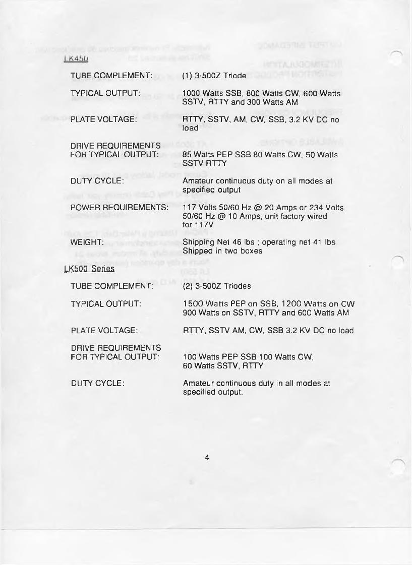
TUBE COMPLEMENT:
TYPICAL OUTPUT:
PLATE VOLTAGE:
DRIVE REQUIREMENTS FOR TYPICAL OUTPUT:
DUTY CYCLE:
POWER REQUIREMENTS:
WEIGHT:
LK5QQ Series
TUBE COMPLEMENT:
TYPICAL OUTPUT:
PLATE VOLTAGE:
DRIVE REQUIREMENTS FOR TYPICAL OUTPUT:
DUTY CYCLE:
(1) 3-500Z Triode
1000 Watts SSB, 800 Watts CW, 600 Watts SSTV, RTTY and 300 Watts AM
RTTY, SSTV, AM, CW, SSB, 3.2 KV DC no load
85 Watts PEP SSB 80 Watts CW. 50 Watts SSTV RTTY
Amateur continuous duty on all modes at specified output
117 Volts 50/60 Hz @ 20 Amps or 234 Volts 50/60 Hz @ 10 Amps, unit factory wired for 117V
Shipping Net 46 lbs ; operating net 41 lbs Shipped in two boxes
(2) 3-500Z Triodes
1500 W atts PEP on SSB, 1200 W atts on CW 900 Watts on SSTV, RTTY and 600 Watts AM
RTTY, SSTV AM. CW, SSB 3.2 KV DC no load
100 Watts PEP SSB 100 Watts CW.60 Watts SSTV. RTTY
Amateur continuous duty in all modes at specified output.
4
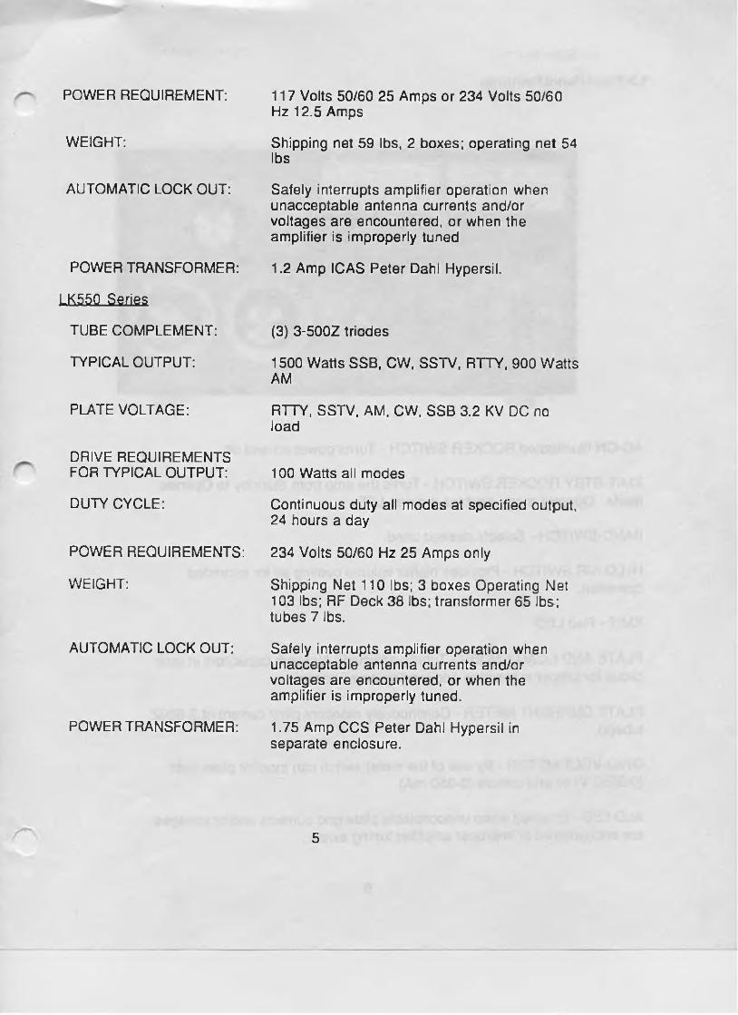
POWER REQUIREMENT:
WEIGHT:
AUTOMATIC LOCK OUT:
POWER TRANSFORMER:
LK55Q Series
TUBE COMPLEMENT:
TYPICAL OUTPUT:
PLATE VOLTAGE:
DRIVE REQUIREMENTS FOR TYPICAL OUTPUT:
DUTY CYCLE:
POWER REQUIREMENTS:
WEIGHT:
AUTOMATIC LOCK OUT:
POWER TRANSFORMER:
117 Volts 50/60 25 Amps or 234 Volts 50/60 Hz 12.5 Amps
Shipping net 59 lbs, 2 boxes; operating net 54 lbs
Safely interrupts amplifier operation when unacceptable antenna currents and/or voltages are encountered, or when the amplifier is improperly tuned
1.2 Amp ICAS Peter Dahl Hypersil.
(3) 3-500Z triodes
1500 Watts SSB, CW, SSTV, RTTY, 900 Watts AM
RTTY, SSTV, AM, CW, SSB 3.2 KV DC no load
100 Watts all modes
Continuous duty all modes at specified output, 24 hours a day
234 Volts 50/60 Hz 25 Amps only
Shipping Net 110 lbs; 3 boxes Operating Net 103 lbs; RF Deck 38 lbs; transformer 65 lbs; tubes 7 lbs.
Safely interrupts amplifier operation when unacceptable antenna currents and/or voltages are encountered, or when the amplifier is improperly tuned.
1.75 Amp CCS Peter Dahl Hypersil in separate enclosure.
5

1.3 Front Panel Features
AC-ON Illuminated ROCKER SWITCH - Turns power on and off.
XMIT-STBY ROCKER SWITCH - Turns the amp from Standby to Operate mode. Operate mode enables a green LED.
BAND-SWITCH - Selects desired band.
HI/LO AIR SWITCH - Provides higher volume cooling air for extended operation.
XM IT- Red LED
PLATE AND LOAD KNOBS - Tuning adjusts Pi-Network capacitors in tank circuit for proper resonance and loading on all bands.
PLATE CURRENT METER - Continuously monitors plate current of 3-500Z tube(s).
GRID-VOLT METER - By use of the meter switch can monitor plate volts (0-3500 V) or grid current (0-350 mA).
ALO LED - Enabled when unacceptable plate/grid currents and/or voltages are encountered or improper amplifier tuning exists .
6

1.4 Rear Apron Features
RF-IN - For connecting to exciter RF output to the amplifier.
RF-OUT - For connecting the LK400/500 series linear amplifier to an antenna.
RLY - For connecting to exciter auxiliary jack to activate T/R Relay in the LK400/500 series amplifiers.
KEY IN - QSK ONLY - station key, must be a bug, hand key or a keyer
KEY OUT - QSK ONLY - hooks to the KEY-IN jack on a QSK transceiver.
QSK VOX SWITCH - place in the QSK position when operating QSK CW.
GROUND LUG - Attach to a good earth ground.
FUSES - 2 holders provided to protect each leg of the AC line.
SERIAL NUMBER - Located on the model type identification sticker.
AC LINE CORD - Connect to proper power requirements only.
PAC-5 PLUG - LK550/LK500 w/optional PAC-5 only. Connects the PAC-5 power transformer to LK550/LK500.
7

CAUTION
NEVER REMOVE /INSERT PLUG WHEN UNIT IS ON OR WHEN THE RF DECK AC LINE CORD IS CONNECTED TO AN AC POWER SOURCE
8

SECTION 2 INSTALLATION
2.1 Introduction
This section describes the unpacking and installation procedures for the LK 400/ 500 series amplifiers.
WARNING
MAKE NO ATTEMPT TO PUT THE AMPLIFIER IN SERVICE OUTSIDE OF THE CABINET—CONTACT WITH VOLTAGE
INTHE AMPLIFIER CAN BE FATAL!!!
2.2 Unpacking
All shipping containers have been specially designed to protect their contents and special care has been taken to prevent damage under normal shipping conditions. Mishandling should be evident upon inspection of the shipping container. If damage is found after visual inspection, take care not to destroy the evidence. If necessary, document the damage with photographs and contact the transport carrier immediately.
Carefully remove your new LK400/500 series linear amplifier from its packing carton, and examine it closely for signs of shipping damage. It is recommended to save all original packing cartons to protect your amplifier from damage should you wish to store it or ship it for after-sales service.
2.3 Warranty Card
Fill out the enclosed warranty registration card and return to Amp Supply within 10 days of original purchase. Keep your original sales slip with the packing cartons should you ever need it for reference.
2.4 Installation
The following subsections describe the installation procedures for the LK 400/500 series amplifiers.
9

2.4.1 Tube Installation
C A U T I O N
ENSURE TUBES ARE INSTALLED PRIOR TO APPLYING POWER TO THE AMPLIFIER
Carefully remove the tubes from their boxes. Carefully move the parasitic chokes in the tube compartment out of the way and install tubes. When securing the plate cap(s), take care not to overtighten screws or tube(s) may be damaged. Remove packing from under the tuned input board.
2.5 Amplifier Placement
In general, the location of your new amplifier is not critical. However, certain precautions must be taken to ensure optimum performance. Avoid extremely hot locations such as near radiators or other heating units. Keep the top of the amplifier case clear of books, papers, or other equipment to protect against overheating. Do not place the amplifiers closer than 2-1/2 inches from a wall.
CAUTION
OBSTRUCTION OF THE SIDES OF THE AMPLIFIER CASE AND THE BLOWER AIR INLET MAY RESULT IN
AMPLIFIER TUBE(S) OVERHEATING
2.6 Power Requirements
Refer to your amplifier series unique specifications for proper power requirements and Figure 2.6.1 for AC line hook-up.
WARNING
NEVER OPERATE ANY AMPLIFIER USING AN EXTENSION CORD
The LK400/500 series is shipped from the factory with jumpers connected to operate on 234 VAC (except LK 450). It is highly recommended that your
1 0

QSK ONLY TRANSCEIVER
FIGURE 2.6.1 AC Line Hook-Up
11

amplifier be operated from its own 234 V - 20 A (or greater) circuit. If a 117 V circuit is all that is available, it should be fused for 30 A with circuit conductors not less than #10. No other equipment should be operated from this 117V circuit. A jumper plug is provided with the amplifier to convert to 117V service.
W A R N I N G
COMPLETELY REMOVE POWER FROM YOUR AMPLIFIER AND ALLOW 30 MINUTES FOR THE HIGH VOLTAGE CAPACITORS
TO DISCHARGE THROUGH BLEEDER RESISTORS BEFORE ATTEMPTING TO CHANGE JUMPER CONNECTIONS
ON BACK OF AMPLIFIER.
Figures 2.6.2 illustrates the jumper connection on the Power Distribution Board, located in the left rear corner of the chassis, for either 117V and 234V operation. The jumper must be inserted as shown or severe damage to your amplifier components may result. Remove existing jumper before installing the new one.
J,220V
OR
J2115V
2.7 Amplifier Installation
After the tubes have been installed, install the top cover and secure with a few screws to finger tight. Connect your amplifier to your power source. Set the amplifier controls as follows:
Figure 2.6.2 Jumper Plug Placement
m ?t»w
AC/ON - OFF XMIT/STBY - STBY METER - VOLTS

Turn the unit on. Plate voltage should read between 3000-3300 Volts DC.Turn the unit off.
2.8 Cable Installation (See Figure 2.8.1)
a. Using a 6 ft. length, connect a 52-Ohm coaxial cable (RG-8U or equivalent) between your transmitter's RF OUTPUT to the LK400/500 series RF INPUT connector.
b. Using another short length of coaxial cable, (RG-8U or equivalent,) connect the LK400/500 series RF OUTPUT connector to a suitable wattmeter.
c. Using the necessary length of coaxial cable, (RG-8U or equivalent) connect the wattmeter output to your antenna system.
d. Select an appropriate length of shielded cable and install an RCA connector on one end and the appropriate connector for your transceiver at the other end.
e. Install the shielded cable between your transmitter accessory contacts on the transmitter rear apron and the RLY plug on the rear apron of your LK400/500 series linear amplifier. These should be normally open contacts capable of carrying 100 mA, which close when you desire to transmit.
f. See your exciter operators manual for details.
2.9 Ground Requirements
For best results your amplifier should be attached to a good earth ground by as short in length, and as large as possible, ground strap. A ground post is provided on the rear apron for this purpose. It is always a good idea to connect the chassis of all associated equipment together and ground them at one point to avoid ground loops. We recommend that all of the equipment in your station be connected together and grounded at the antenna tuner.
13

EXCrTER LK400/500 TO 50 OHM
Figure 2.8.1 Cable Installation

SECTION 3 TUNING
3.1 Tuning Procedure
This section describes the tuning procedure for the LK400/500 series linear amplifiers. Follow all steps carefully to insure optimum performance of your amplifier. Read all tuning steps before actually tuning your amplifier.
CAUTION
THIS UNIT IS SHIPPED READY FOR 234 VAC OPERATION (EXCEPT LK450). REFER TO INSTALLATION INSTRUCTIONS FOR 117V OPERATION.
1. Set the BANDSWITCH to the desired band. If your amplifier is model LK450/500/550NTC, go to step 4, otherwise proceed on to step 2.
2. Set the LOAD control on num ber shown on Tuning Chart.
3. Set the PLATE control on number shown on Tuning Chart.
4. Set the ON/AC control to ON.
5. Select the correct antenna for the band selected. Insure antenna VSWR is acceptable before proceeding.
6. Set the XMIT/STBY control to XMIT. The green LED indicates the am plifier is in the Ready To Operate mode. If your am plifie r is model LK500NTC, go to step 7, otherw ise proceed to step 8.
7. Set Meter switch to grid current (this is read on Plate Voltage/Grid Current Meter).
8. Insert a small amount of exciter drive until the plate current begins to rise to approximately 400mA. If your amplifier is model LK450/500/550NTC, go to step 16, otherwise proceed to step 9.
16

9. Rotate the PLATE control for m axim um output on your station w att meter.
10. A lternate between PLATE and LOAD for m axim um output.1 KW input (Plate Voltage x Plate Current = Power Input)
Example: Plate Current = 400mAPlate Voltage = 2500 VDC .4 x 2500 V = 1000 Watts Input
11. Increase drive power. Repeat steps 8 through 10 until you obtain maximum power output.
12. During tune up alternately monitor Grid and Plate Current.
13. Grid current can be reduced by slightly decreasing the Load control. Turn control to right, clockwise.
14. ALWAYS TUNE FOR MAXIMUM OUTPUT!
15. Increase drive from the exciter until a further increase in exciter drive does not increase amplifier output power.
16. SPECIAL INSTRUCTIONS — ALL NO-TUNE MODELS
Rotate FINE control to achieve peak am plifier output.
Rotate QSK control ON to enable QSK mode if desired.
17. W hen your station w attm eter indicates maximum am plifie r power output, return the exciter to receive mode. Select desired transm itte r or transceiver operating mode, and you are now ready to operate.
17
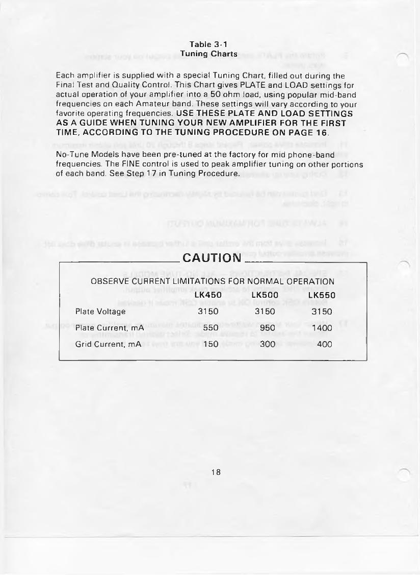
Table 3-1 Tuning Charts
Each am plifier is supplied w ith a special Tuning Chart, filled out during the Final Test and Quality Control. This Chart gives PLATE and LOAD settings for actual operation of your am plifier into a 50 ohm load, using popular mid-band frequencies on each Am ateur band. These settings w ill vary according to your favorite operating frequencies. USE THESE PLATE AND LOAD SETTINGS AS A GUIDE WHEN TUNING YOUR NEW AMPLIFIER FOR THE FIRST TIME, ACCORDING TO THE TUNING PROCEDURE ON PAGE 16.
No-Tune Models have been pre-tuned at the factory for mid phone-band frequencies. The FINE control is used to peak am plifie r tun ing on other portions of each band. See Step 17 in Tuning Procedure.
CAUTION
OBSERVE CURRENT LIMITATIONS FOR NORMAL OPERATION
LK450 LK500 LK550
Plate Voltage 3150 3150 3150
Plate Current, mA 550 950 1400
Grid Current, mA 150 300 400
18

SECTION 4 AMPLIFIER CARE
4.1 IntroductionThis section provides instructions on the care and cleaning of the LK 400/500
series amplifiers.
WARNING
EXTREME CARE MUST BETAKEN WHENEVER MAKING ANY ADJUSTMENTS INSIDE ANY LINEAR AMPLIFIER
4.2 Cleaning Amplifier Compartment
After completely disconnecting your amplifier from the power source, wait 30 minutes so all electrolytic capacitors have discharged through their bleeder resistors. The top cover can then be safely removed by taking out the top and side row of screws.
Since the amplifier compartment is forced-air cooled, it will collect particles of dust which must be periodically removed. The frequency of cleaning will be governed by how many hours the amplifier is operated, and by operating environment cleanliness. When the blower blade accumulates a large amount of dust, the amplifier should be cleaned. The best way to clean the amplifier is to remove the top cover and blow the dust out with compressed air. If compressed air is not available, a soft-bristled one- inch paint brush can be used to brush the amplifier clean.
CAUTION
DO NOT BLOW AIR DIRECTLY INTO THE FAN BLADES.USE A BRUSH IN CLEANING THE BLADES OF THE FAN
4.3 Tube Replacement
If it becomes necessary to replace the tubes in the amplifier the same brand should be used. A new tube kit is available from Amp Supply Co.
2 0

Table 4-2TROUBLESHOOTING CHART(CONT’D)
SYMPTOM CASE REMEDY
Amplifier always in transmit mode
Amp will not load
Relay Control cable is shorted
Check center to shield for continuity: Re-do Relay Control cable
Check Bandswitch setting Wrong antenna selected XMIT/STBY switch in STBY
r25

LIMITED WARRANTY
Amp Supply Company warrants to the original purchaser that this product shall be free from defects in material (except tubes and RF output transistors) or workmanship for two (2) years from the date of original purchase.
During the warranty period, the Amp Supply Company or an authorized Amp Supply Company service facility will provide free of charge both parts (except tubes and RF output transistors) and labor necessary to correct defects in material or workmanship.
To obtain such warranty service, the original purchaser must:
(1) Complete and send in the Warranty Registration Card.
(2) Notify Amp Supply Company or its nearest authorized service facility, as soon as possible after discovery of a possible defect, of:
(a) The model number and serial number, if any;(b) The identity of the seller and the approximate date of purchase;(c) A detailed description of the problem, including details on the
electrical connection in associated equipment and the list of such equipment.
(3) Deliver the product to the Amp Supply Company or the nearest authorized service facility, or ship the same in its original container or equivalent, fully insured and shipping charges prepaid.
Correct maintenance, repair and use are important to obtain proper performance from this product. Therefore, carefully read the Instruction Manual. This warranty does not apply to any defect that Amp Supply Company determines is due to:
(1) Improper maintenance or repair, including the installation of parts or accessories that do not conform to the quality and specifications of the original parts.
(2) Misuse, abuse, neglect or improper installation.
(3) Accidental or intentional damage. All implied warranties, if any, terminate one (1) year from the date of the original purchase.
The foregoing constitutes Amp Supply Company's entire obligation with respect to this product, and the original purchaser and any user or owner shall have no other claim for incidental or consequential damages. Some states do not allow the exclusion or limitation of incidental or consequential damages, so the above limitation and exclusion may not apply to you.
This warranty gives specific legal rights and you may also have other rights which vary from state to state.
26

WARNINGS
MAKE NO ATTEMPT TO PUT THE AMPLIFIER IN SERVICE OUTSIDE OF THE CABINET. CONTACT WITH HIGH VOLTAGES FOUND IN THE AMPLIFIER CAN BE FATAL.
NEVER OPERATE ANY AMPLIFIER FROM AN EXTENSION CORD.
COMPLETELY REMOVE POWER FROM YOUR AMPLIFEIR AND ALLOW 30 MINUTES FOR THE HIGH VOLTAGE CAPACITORS TO DISCHARGE THROUGH BLEEDER RESISTORS BEFORE ATTEMPTING TO CHANGE JUMPER CONNECTIONS IN BACK OF AMPLIFIER.
CAUTIONS
NEVER REMOVE/INSERT PLUG WHEN UNIT IS ON OR WHEN THE RF DECK AC LINE CORD IS CONNECTED TO AN AC POWER SOURCE.
ENSURE TUBES ARE INSTALLED PRIOR TO APPLYING POWER TO THE AMPLIFIER.
OBSTRUCTION OF THE SIDES OF THE AMPLIFIER/CASE AND THE BLOWER AIR INLET MAY RESULT IN AMPLIFIER TUBE(S) OVERHEATING.
THE UNIT IS SHIPPED READY FOR 234VAC OPERATION. REFER TO INSTALLATION INSTRUCTIONS FOR 117V OPERATION.
OBSERVE CURRENT LIMITATIONS FOR NORMAL OPERATION.
DO NOT BLOW AIR DIRECTLY INTO FAN BLADES. USE A BRUSH FOR CLEANING THE BLADES.
A - 2
• gt
• g •
GRID IN J1 -1
J 1 - 2
•R3 N O R MA L L Y OPEN
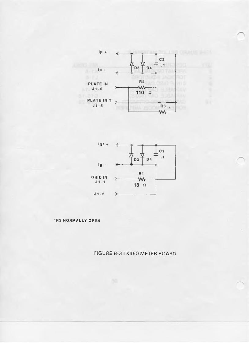
FIGURE B-3 LK450 METER BOARD

LK450 METER BOARD BILL OF MATERIALS
OTY DESCRIPTION REF. DESIG.4 1N5408 DIODE D1-42 0.1 uF 63V CAP C1,21 18 OHM 1/4W 5% RES R11 110 OHM 1/4W 5% RES R21 .15 OHM 3W 5% RES R3 ‘ NORMALLY OPEN*1 6 PIN PC MT MOLEX J1
B7

)
FIGURE B-10 LK450 NO TUNE UP RF CIRCUIT
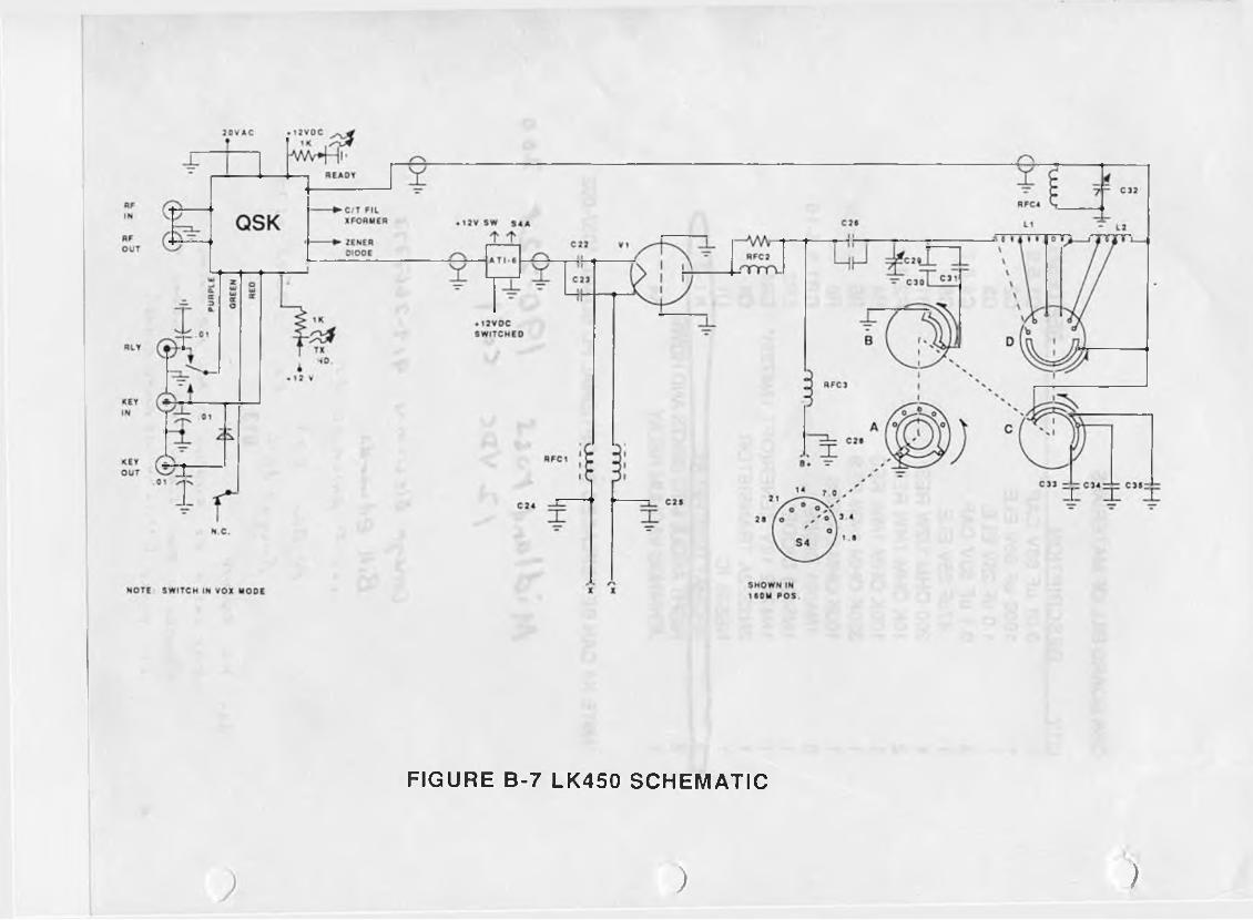
FIGURE B-7 LK450 SCHEMATIC
) )

C T O .
FIGURE B-11 LK500 NO TUNE UP RF CIRCUIT

HF
IN
«FO U T
R L Y
KEY
IN
KE Y
OUT
N O T E ;
) o
FIGURE B-8 LK500 SCHEMATIC
C70 - 7«
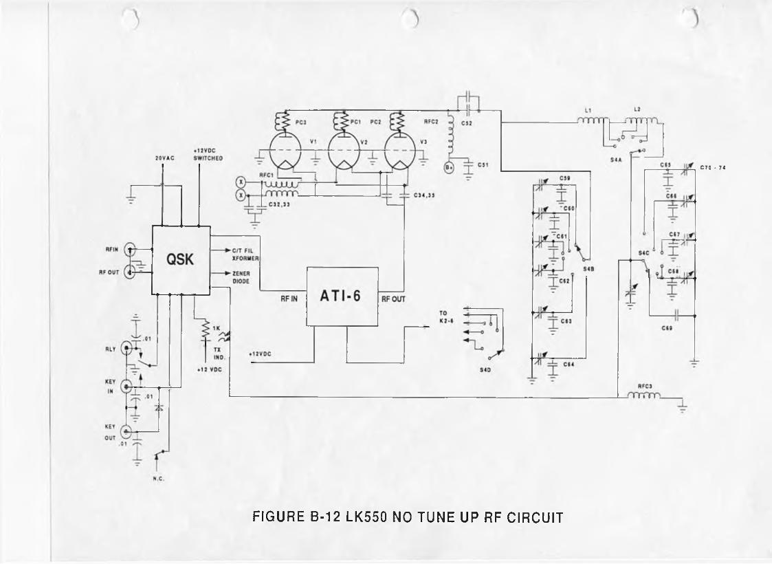
FIGURE B-12 LK550 NO TUNE UP RF CIRCUIT
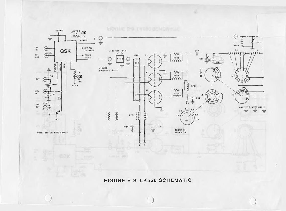
FIGURE B-9 LK550 SCHEMATIC
) )
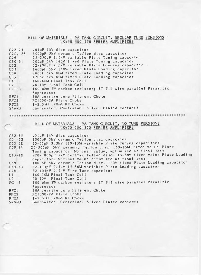
O F M A T E R I A L S - P A T A N K C I R C U J J ^ R E G U L A R T U N E VERSIONS
L K O 0 z 500-550 S E R I E S A M P L I F I E R S
C 2 2 - 2 5 .OluF lkV disc capacitorC26, 28 lOOOpF 5kV ce r a m i c T e f l o n disc c a p a c i t o r
C 2 9 75-250pF 3.5kV v a r i a b l e Plate T u n i n g capacitor
C 3 0 - 3 1 J_OOp_F 5kV 160M fixed P l a t e T u n i n g capacitorC 3 2 32-800pF 2.5kV v a r i a b l e Plate L o a d i n g capacitor
C 3 3 1400pF 5kV 160M fixed P l a t e L o a d i n g capacitor
C 3 4 940pF 5kV 8 0 M fixed P l a t e L o a d i n g capacitorC 3 5 470pF 5kV 4 0M fixed P l a t e L o a d i n g capacitor
LI 160-40M Final Tank Coil
L 2 2 0 - 10M Final Tank CoilPCI-3 100 o h m 2W ca rbon resistor; 3T //16 wir e parallel P a r a s i t i c
Suppres sor
RFC1 30A ferrite core F i l ament C h o k e
RFC2 PCI 000 -2A Plate C h o k e
RFC3 1 -2 . 5rrH 1 70rrA R F C h o k eS 4 A - D Bandswitch, C e n t r a l a b . Silver P l a t e d contacts
B^LL O F M^TERj_ALS - P A T A N K Cj_RCUIT± N O - T U N E V E R S I O N S
L K 4 5 0 - 5 0 0 - 5 5 0 S E R J E S A M P L I F I E R S
C32-35 .OluF lkV disc capacitorC 5 1 - 5 2 lOOOpF 5kV ceramic T e f l o n disc c a p a c i t o r
C 5 3 - 5 8 I 0 - 50pF 3 . 3kV 160-15M v a r i a b l e P l a t e Tuni n g c a p a citors
C.59-64 2 5 - 5 0 0 p F 5kV c e r a m i c T e f l o n disc. 1 6 0 - 1 5 M fixe d - v a l u e Plate Tuning capacitor. N o m i n a l value, o p t i m i z e d at final test
C6 5-68 ^ 70- 1 O O O p F 5kV c e r a m i c T e f l o n disc. 15-80M fixe d - v a l u e P l a t e Loading
capacitor. Nominal value o p t i m i z e d at final test
C69 U O O p F 5kV ce r a m i c T e f l o n disc. 160M fixed Plate L o a d i n g capacitor
C 7 0 - 7 3 32- 10 5pF 2.5kV 1 5 - 8 0 M v a ri a b l e P l a t e Loading capacitor
C 74 3 2 - 1 0 5 p F 2.5kV F ine T u n e c a p a c i t o r
LI 160-40M Final Tank Coil
L2 20 -10M Final Tank CoilPCI-3 100 o h m 2W ca rbon resistor; 3T //16 w i r e parallel P a r a s i t i c
Suppres sor
RFC1 30A ferrite core F i l a m e n t C h o k e
RFC2 PCI 000 -2A Plate C h o k e
RFC3 1 -2 . 5rrH 1 70rrA R F C h o k eS 4 A - D Bandswitch, C e n t r a l a b . Silver P l a t e d contacts

0 o o o J9
R1--20W--300 OHM
]0
J6 J5 J4 J3 J2
J1
h iu
J1
&A AC-F1 1«#-
CHASSIS GD. 2 CHASSIS GD. a
A C - P Ä f 2 4 I J2 I
ON-A
ON-B HI/LO A
HI/LO B
1 ^
4
3**
EXT-PAK
230 - A
230-B
1 10-A
1 10-B
2 **—J6
i -« -2 * —3^- 4 +rJ8
FROM TUBE DK
FROM DELAY 2
CHASSIS GD 3«*-
SPARE
BLOWER
J9
2
3
4
R1 R2
J3
J4 —►
J5■ 1
-►2
“ ► 3- ► 4J7- ► i
■►2
-►3
TO T1
TO T2
117/234
JUMPER
FILAMENT A
FILAMENT B
F IG U R E B-4
PO W ER D IS TRIBUTIO N
BOARD
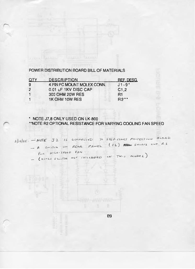
POWER DISTRIBUTION BOARD BILL OF MATERIALS
QIX_____QESgBiEnON________________ BEF.DESQ.9 4 PIN PC MOUNTMOLEXCONN. J 1 -9 *2 0.01 uF 1KV DISC CAP C1.21 300 OHM 20W RES R11 1K OHM 10W RES R 2 #*
* NOTE J7,8 ONLY USED ON LK-800“ NOTE R2 OPTIONAL RESISTANCE FOR VARYING COOLING FAN SPEED
S^-iTch (IÇAO-
Po*c- H* l k - £ fex-& Fa **
_ £ M / - i-o ; u j Ten
( c / 'l fivr-i I o mT fi- 1. _ ß fZ^AfZ. J
. r n rA rJ
a/or / w c c UJ>*& ^ ™ ' J /*«**>« O
B9
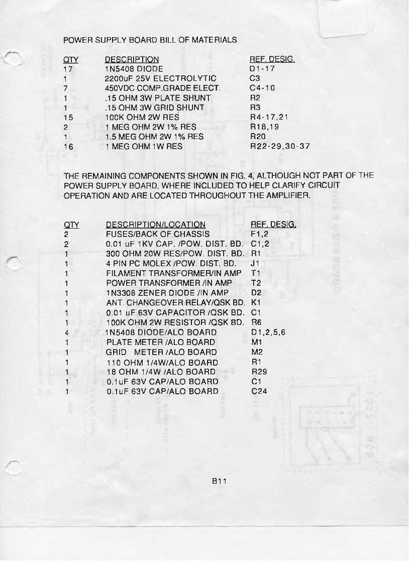
POWER SUPPLY BOARD BILL OF MATERIALS
QTY DESCRIPTION R.EF:.D£Si£.17 1N5408 DIODE D 1 -1 71 2200uF 25V ELECTROLYTIC C37 450VDC COMP.GRADE ELECT. C4-101 .15 OHM 3W PLATE SHUNT R21 .15 OHM 3W GRID SHUNT R315 100K OHM 2W RES R4-1 7,212 1 MEG OHM 2W 1% RES R1 8,1 91 1.5 MEG OHM 2W 1% RES R2016 1 MEGOHM 1WRES R 22-29,30-37
THE REMAINING COMPONENTS SHOWN IN FIG. 4, ALTHOUGH NOT PART OF THE POWER SUPPLY BOARD, WHERE INCLUDED TO HELP CLARIFY CIRCUIT OPERATION AND ARE LOCATED THROUGHOUT THE AMPLIFIER.
QTY DESCRIPTION/LOCATION REF; PES1 £2 FUSES/BACK OF CHASSIS F1.22 0.01 uF 1KV CAP./POW. DIST. BD. C1,2
300 OHM 20W RES/POW. DIST. BD. R14 PIN PC MOLEX /POW. DIST. BD. J 1FILAMENT TRANSFORMER/IN AMP T1POWER TRANSFORMER /IN AMP T21N3308 ZENER DIODE /IN AMP D2ANT. CHANGEOVER RELAY/QSK BD. K10.01 uF 63V CAPACITOR /QSK BD. C1100K OHM 2W RESISTOR/QSKBD. R61N5408 DIODE/ALO BOARD D1,2,5,6PLATE METER /ALO BOARD M1GRID METER /ALO BOARD M2110 OHM 1/4W/ALO BOARD R118 OHM 1/4W /ALO BOARD R290.1 uF 63V CAP/ALO BOARD C10.1 uF 63V CAP/ALO BOARD C24
B11

pn
rrrr
< 5Kl
RSm -
C1
r+O-i -W-. D1.2
OSK
fW -,-{>f— D5.6
DI
STB OPER
.12V
SWfTCHEO
m V v W A r A W A r W v r m V ^ M T ^ V W -
— 11—^— 11-- —II---L -II-' i 11 I II I lh ^
Vv\^rvW -fW v^W vV^TvVvV
CIRCUIT BOARD
—II—Ri C1
■ PS. - '
m
Ml
H HC24
I R29
G S
■A/VWV
S2
04.17R2 R3
C 4-10
R22 • 28
/0 2 - 1 7
iSIS-
- 0
RI«
RIO
R20
R30.37R21
x W W -
CHASSIS
POWER SUPPLY
CIRCUIT BOARD
FIGURE B-5 POWER SUPPLY
f (
Ck.

OSK OPERATION WARNING!
QSK OPERATION WITH YOUR LK450-500-550 SERIES AMPLIFIER IS ENABLED ONLY
IF YOUR KEY, KEYER OR COMPUTER WITH PROPER INTERFACE IS PLUGGED INTO THE
KEY IN JACK ON THE REAR PANEL OF YOUR AMPLIFIER, AND THE KEY OUT JACK
LINE IS ROUTED TO THE TRANSCEIVER KEYING INPUT. THE QSK CIRCUITRY IN THE
AMPLIFIER MUST CONTROL THE QSK FEATURES OF YOUR TRANSCEIVER. FAILURE TO
OBSERVE PROPER INTERCONNECTION PROCEDURES WILL RESULT IN DAMAGE TO
THE QSK SYSTEM AND WILL VOID YOUR WARRANTY.
SEPTEMBER 1, 1988
QSK BOARD BILL OF MATERIALS
Q IÏ ._____ DES.C.BIPJLQ.N___________________ REF,D£SKL4 0.01 uF 63V CAP C1.5.91 100C uF 50V ELE. C21 1.0 uF 25V ELE. C33 0.1 uF 63V CAP C4,6,71 .47uF 25V ELE C81 200 OHM 1/2W RES R12 IOKOHM 1/4W RES R2,3 1 IOOKOHM 1/4W RES R41 330KOHM 1/4W RES R51 100K OHM 2W RES R69 1N4001 DIODE CR1,3,5-101 1N5408 DIODE CR21 1N4742 12V ZENER(OPT.1 N4739)* CR41 2N2222A TRANSISTOR Q11 NE555 IC U1
r a r * — A M ü ra a ru ijü b u i l a v_ n g 1 - 32 RIGHT ANGLE MTG BRKTS AND HDWE1 JENNINGS VACUUM RELAY K4 *
•NOTE K4 CAN BE REPLACED BY OPTIONAL PC BOARD 1037-002
A t / " o i - T
( O- VDC Ca t I
k /<f c t y w -l s C f / ^ 2 66-7 ^ "73
ß i HI O I ft- A t Lrl-W* O $ f
p o ß o x $ -7 f / / * j , /< v c 2 n S v - r - o s ' ! ' )/ ( * i e, A f
B13KZ /¿ep/fiffV
2(f\s Ck.7 7b KYPftSSifP T° W**-'
M o^tSTcp o* F M fc / i-e w
Ci.Sk { 17 ,J ¿<i> AV<xfy £ t i A n & )

( ( <
LM393
PLATE * J1-6
PLATE . J1-5
N OTES:
1 • R30 15 0 H M 3W USED IN LK8002 ‘ R30 33 OHM InlW USED IN LK550
R29 33 0 H M V 4 W U SE D IN LK550
R28
TO FAULT LAMP
FIGURE B-1 ALO METER BOARD

ALO METER BOARD BILL OF MATERIALS
Q IY_____ DESCBiP-TlQJj__________________ REF, DES1&2 6 PIN PC MOUNT MOLEX CONN. J 1,21 7808 8 VOLT REGULATOR IC U11 LM324 OP AMP U21 LM 393 COMPARATOR U31 NE555 TIMER U44 1N5408 DIODE D1.2,5,65 1N4148 DIODE D3,4,8,9,11 1 1N4742 DIODE D71 2N2222A TRANSISTOR Q11 AROMAT D2SE RELAY K12 200 OHM 1/2 WATT POT VERT MT. R11.233 HIGH MU FERRITE BEADS CN20 L 1 - 3 1 110 OHM 1/4 W 5% RESISTOR R14 2.2KOHM 1/4 W 5% RES R2-59 10K OHM 1/4 W 5% RES R6-8.1 2,12,1 5
17,20,253 1K OHM 1/4 W 5% RES R9,19,281 15KOHM 1/4 W 5% RES R102 1 MEGOHM 1/4 W 5% RES R14.214 47KOHM 1/4 W 5% RES R16,18,31,32 1 1.4K OHM 1/4 W 5% RES R221 2K OHM 1/4 W 5% RES R241 220KOHM 1/4 W 5% RES R261 330 OHM 1/4 W 5% RES R271 18 OHM 1/4 W 5% RES R291 .15 OHM 3 WATT 5% RES R30 *IN LK800 ONLY*14 0.1 uF 63 V CAP C1,2,4,5,9,11,13,14
16,17,19,22,23,248 • 0.01 uF 63 V CAP C3,6,7,8,10,12,18,20
4 10uF 25V ELECTROLYTIC C15,21,25,27
B3

C1 *
16 K2 1
t rC2
16 K3 !
n rC3
16 K4 1
C4
16 K5 1
wC5
16 K6 1r r r rr r r r v .
\♦ SHOWN IN 160M POS.
V I/
13
r r r r r r x x¡ ™ X # C7
11 L2
—*— ®-^OnO —a---- •-----l / f * 0c
i 4 = - z, C 2 1 i ^ l 0 9 C 10T Ì C22
11 L3
5° N ^ 1— , - r r m -
Ì #■C11 C12
X
---- -4
6
A / 0
C24
11
N 13,? I >0 — '
L4
I• C25. I
X r r r C L
- 1XI
“ - Ì - C 1 3 C14 ~
IC26 I
I
11
13L5
■ r r r C L xI ,
> r ° .
I C27 _ _1L_C15 C 1 6 _ J _ — C28
11
, ° N
L613
- r r r r x
- g
- 4 t-C17 C 1 8 Ì T
c >
\ k RF IN
\ k RF OUT
-C)
12 VDC
SWITCHED THRU BAND SW.
FIGURE B-2
ATI-6 BOARD
160 M
80 M
40 M
20 M
15 M
10 M OPTION
•NOTE C l .2.3 USED IN NTS ONLY

ADDENDUM TO L K 4 5 0 - 5 0 0 - 5 5 Q SERIES AMPLIFIER OWNER'S MANUAL
1) Revised Instructions: Page 6 - 1.3 Front Panel Features
F R O N T P A N E L C O N T R O L S
PWR OFF—ON ROCKER SWITCH — Turns AC Power on and off.
MODE XMIT—STBY ROCKER SWITCH - Turns amplifier fi'om Standby to Opei'ate mode.
METER GRID-VOLT ROCKER SWITCH - Chooses Grid Current or Plate Voltagemetering for PA Tube.
QSK OFF-ON ROCKER SWITCH - Enables QSK (Full Break-In CW) or VOX (PTT)mode.
* * * * * * * * * * * * * * * * * * * * * * * * * *
2) Revised Instructions: Page B9 - Power Distribution BoardBill of Materials
An important modification has now been made to all our amplifiers. Step- Start (filament current inrush) protection has been added to improve PA tube and Power Supply component life. This subchassis is mounted on standoffs directly above the Power Distribution Board. The components include a SPDT Relay (30A contacts) and a 20 ohm. 20W resistor. Upon initial power-up. the resistor is switched in series with the main AC input. and dissipates excessive current during the first quarter AC cycle. after which the relay switches the resistor out the circuit and full voltage is applied to the input of the Power Transformer.
August 12, 1988

!['-[TIm(]mw LINEAR mmmorn AMPLIFIERS](https://static.fdocuments.net/doc/165x107/627d68e2cdea8440335b5b3f/-timmw-linear-mmmorn-amplifiers.jpg)