Ljj.ans.Hive.no_pdf_User Guide PDF's EdgeCam 12.5_userGuide
1173
Edgecam User Guide Copyright© 1988 - 2008 Pathtrace All Rights Reserved 1 Edgcam User Guide
-
Upload
hari-prakash -
Category
Documents
-
view
85 -
download
1
Transcript of Ljj.ans.Hive.no_pdf_User Guide PDF's EdgeCam 12.5_userGuide

Edgecam User GuideCopyright© 1988 - 2008
Pathtrace
All Rights Reserved
1
Edgcam User Guide
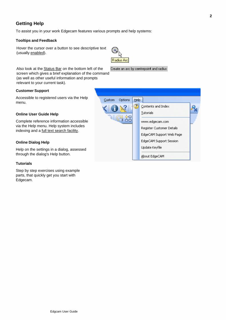
Getting Help
To assist you in your work Edgecam features various prompts and help systems:
Tooltips and Feedback
Hover the cursor over a button to see descriptive text(usually enabled).
Also look at the Status Bar on the bottom left of thescreen which gives a brief explanation of the command(as well as other useful information and promptsrelevant to your current task).
Customer Support
Accessible to registered users via the Helpmenu.
Online User Guide Help
Complete reference information accessiblevia the Help menu. Help system includesindexing and a full text search facility.
Online Dialog Help
Help on the settings in a dialog, assessedthrough the dialog's Help button.
Tutorials
Step by step exercises using exampleparts, that quickly get you start withEdgecam.
2
Edgcam User Guide
About Edgecam
Edgecam offers you a complete CAM solution, enabling you to quickly produce CNC code for imported orinternally-generated part designs, and giving you control over all the stages of the process.
You can:
Import part design geometry:
Import designs from a wide variety of CAD packages including Autodesk Inventor, SolidWorks,CATIA V5, SolidEdge, UGS NX, Pro/Engineer.
Import solid model designs in a wide variety of interface formats, including STEP, IGES, SAT,DWG, DXF, VDA.
Or create your own geometry:
Create surfaces and wireframe within Edgecam for part design and toolpath control.
Create machining:
Base your milling and turning on wireframe, surface or solid geometry.
Quickly create toolpaths with many automated settings using operations. To fine tune thetoolpaths, edit the cycles within the operations (or create cycles directly).
Choose tools from a comprehensive tooling database:
You use the 'ToolStore' supporting application.
Input your own tooling data or import from 3rd party suppliers.
Automate speed and feed selection using stored tooling and material data.
Create milling machining:
Create a wide variety of machining such as roughing, profiling and facing, using strategiessuch as lace, flowline and waterline (z-level).
Create up to 5 axis machining - multi-index and simultaneous.
Create turn machining:
Create a wide variety of machining including rough and finish turning, rough and finishgrooving.
Create multi turret and multi-spindle machining.
Program twin turrets independently, with manual synchronisation, or use the 'balanced'cycles with automatic synchronisation.
Incorporate milling machining with a mill/turn machine.
Create 2 to 4 Axis Wire EDM.
Create configurations supporting your machine tools:
Use the 'Code Wizard' supporting application to configure your machine tool capabilities into asingle 'Code Generator' (post-processor) file, for quick selection.
Configure multi-axis (linear and rotary) milling machines and turning machines. Use the 'get you
3
Edgcam User Guide
started' templates for many popular machines and controllers including Fanuc, Okuma, Daewoo.
Include a graphical representation of your machine using the provided, or custom (solid model)graphics.
Simulate your machining:
Watch you part being machined in a graphical representation of your machine, checking forcollisions and so on.
Generate CNC code for your machining, tailored by your stored machine configuration.
Quickly manipulate your machining:
Automatically adapt your machining to external changes in the solid part file ('associativity').
Change the order of the machining.
Mirror and copy toolpaths
Edit parameters such as tool diameters, with instant toolpath regeneration.
Create automated tasks
Use Edgecam's 'PCI' macro language.
4
Edgcam User Guide

About Part Modeler
Part Modeler is an entry-level procedural solids modelling program, providing:
Easy-to-use and cost-effective solid modeling for parts and assemblies.
Features for many manufacturing-specific tasks, such as designing moulds and dies or generatingelectrodes.
Seamless integration with Edgecam Solid Machinist, providing a complete system for creating andmachining true solids-based parts with Automatic Feature Recognition and full part-to-tooplathassociativity.
Loading of open files directly into Edgecam using the Launch Edgecam icon.
5
Edgcam User Guide
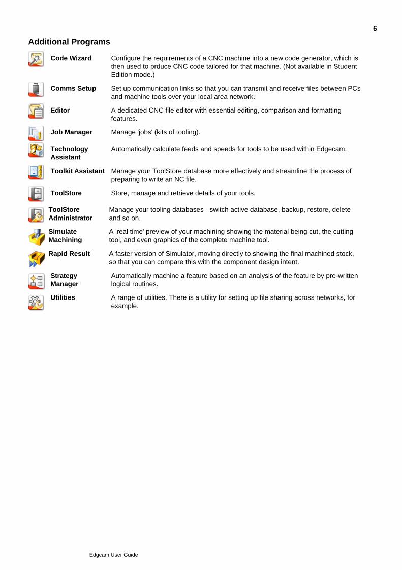
Additional Programs
Code Wizard Configure the requirements of a CNC machine into a new code generator, which isthen used to prduce CNC code tailored for that machine. (Not available in StudentEdition mode.)
Comms Setup Set up communication links so that you can transmit and receive files between PCsand machine tools over your local area network.
Editor A dedicated CNC file editor with essential editing, comparison and formattingfeatures.
Job Manager Manage 'jobs' (kits of tooling).
TechnologyAssistant
Automatically calculate feeds and speeds for tools to be used within Edgecam.
Toolkit Assistant Manage your ToolStore database more effectively and streamline the process ofpreparing to write an NC file.
ToolStore Store, manage and retrieve details of your tools.
ToolStoreAdministrator
Manage your tooling databases - switch active database, backup, restore, deleteand so on.
SimulateMachining
A 'real time' preview of your machining showing the material being cut, the cuttingtool, and even graphics of the complete machine tool.
Rapid Result A faster version of Simulator, moving directly to showing the final machined stock,so that you can compare this with the component design intent.
StrategyManager
Automatically machine a feature based on an analysis of the feature by pre-writtenlogical routines.
Utilities A range of utilities. There is a utility for setting up file sharing across networks, forexample.
6
Edgcam User Guide
Remembering Settings
The 'modality' functionality speeds up your work by remembering settings.
When you open a dialog, the 'Modal' options are initially as you last set them, while the 'Non-Modal' options arealways at a default setting (such as blank for numbers).
To change the modal settings for a command
Click Options menu Preferences Modality tab Customise Mode to check it.1.
Select a command to open its dialog.
Use the menus rather than toolbar buttons, as buttons do not always open a dialog.
2.
Click OK to open a second version of the dialog, with Modal/Non Modal options (some options may alsoinclude a PCI variable name).
3.
Make the Modal or Non-Modal settings as required and click OK.4.
Repeat steps 2, 3 and 4 for all commands that you want to alter.5.
Repeat step 1 to un-check Customise Mode.6.
Note: If you change the value of a modal option when editing an instruction the value will only apply to thatinstruction. All other instructions that use the option will still use the original value.
To reset the modal settings to the installed defaults
Click Options menu Preferences Modality tab Reset Defaults.
7
Edgcam User Guide
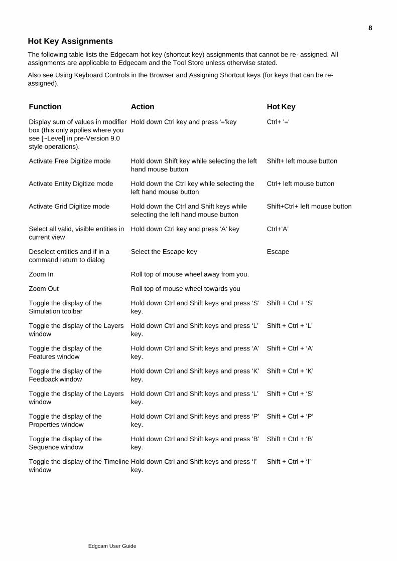
Hot Key Assignments
The following table lists the Edgecam hot key (shortcut key) assignments that cannot be re- assigned. Allassignments are applicable to Edgecam and the Tool Store unless otherwise stated.
Also see Using Keyboard Controls in the Browser and Assigning Shortcut keys (for keys that can be re-assigned).
Function Action Hot Key
Display sum of values in modifierbox (this only applies where yousee [~Level] in pre-Version 9.0style operations).
Hold down Ctrl key and press '='key Ctrl+ '='
Activate Free Digitize mode Hold down Shift key while selecting the lefthand mouse button
Shift+ left mouse button
Activate Entity Digitize mode Hold down the Ctrl key while selecting theleft hand mouse button
Ctrl+ left mouse button
Activate Grid Digitize mode Hold down the Ctrl and Shift keys whileselecting the left hand mouse button
Shift+Ctrl+ left mouse button
Select all valid, visible entities incurrent view
Hold down Ctrl key and press ‘A’ key Ctrl+’A’
Deselect entities and if in acommand return to dialog
Select the Escape key Escape
Zoom In Roll top of mouse wheel away from you.
Zoom Out Roll top of mouse wheel towards you
Toggle the display of theSimulation toolbar
Hold down Ctrl and Shift keys and press ‘S’key.
Shift + Ctrl + ‘S’
Toggle the display of the Layerswindow
Hold down Ctrl and Shift keys and press ‘L’key.
Shift + Ctrl + ‘L’
Toggle the display of theFeatures window
Hold down Ctrl and Shift keys and press ‘A’key.
Shift + Ctrl + ‘A’
Toggle the display of theFeedback window
Hold down Ctrl and Shift keys and press ‘K’key.
Shift + Ctrl + ‘K’
Toggle the display of the Layerswindow
Hold down Ctrl and Shift keys and press ‘L’key.
Shift + Ctrl + ‘S’
Toggle the display of theProperties window
Hold down Ctrl and Shift keys and press ‘P’key.
Shift + Ctrl + ‘P’
Toggle the display of theSequence window
Hold down Ctrl and Shift keys and press ‘B’key.
Shift + Ctrl + ‘B’
Toggle the display of the Timelinewindow
Hold down Ctrl and Shift keys and press ‘I’key.
Shift + Ctrl + ‘I’
8
Edgcam User Guide

Toggle the display of theTracking window
Hold down Ctrl and Shift keys and press ‘C’key.
Shift + Ctrl + ‘C’
Toggle the display of theSimulation window
Hold down Ctrl and Shift keys and press ‘S’key.
Shift + Ctrl + ‘S’
Toggle the display of the Statuswindow
Hold down Ctrl and Shift keys and press ‘T’key.
Shift + Ctrl + ‘T’
Rotate model up in active view Hold down Ctrl key and select Up arrow key.Or right-click and drag.
Ctrl+ Up arrow
Rotate model down in active view Hold down Ctrl key and select Down arrowkey. Or right-click and drag.
Ctrl+ Down arrow
Rotate model left in active view Hold down Ctrl key and select Left arrow key Ctrl+ Left arrow
Rotate model right in active view Hold down Ctrl key and select Right arrowkey
Ctrl+ Right arrow
Pan model in active view Click and drag using mouse wheel.
Pan model up in active view - XZClip Plane (Analysis model)
Hold down Shift key and select Up arrow key Shift+ Up arrow
Pan model down in active view -XZ Clip Plane (Analysis model)
Hold down Shift key and select Down arrowkey
Shift+ Down arrow
Pan model left in active view - XZClip Plane (Analysis model)
Hold down Shift key and select Left arrowkey
Shift+ Left arrow
Pan model right in active view -XZ Clip Plane (Analysis model)
Hold down Shift key and select Right arrowkey
Shift+ Right arrow
Toggle between selected entities(Edgecam only, not available in
ToolStore)
Toggle between entities in Intellisnapselection area
Tab key (forward)
Shift+ Tab key (backward)
Rotate locking X axis Select the X key and rotate X
Rotate locking Y axis Select the Y key and rotate Y
Rotate locking Z axis Select the Z key and rotate Z
To copy an instruction using thebrowser
Select the instruction(s), hold down the Ctrlkey and drag to a new location in thesequence.
Ctrl+ hold down left mouse button
9
Edgcam User Guide
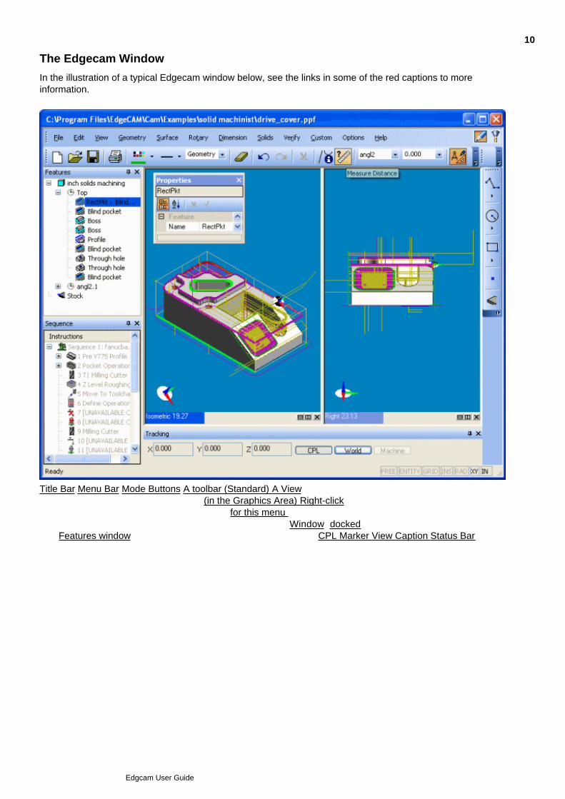
The Edgecam Window
In the illustration of a typical Edgecam window below, see the links in some of the red captions to moreinformation.
Title Bar Menu Bar Mode Buttons A toolbar (Standard) A View(in the Graphics Area) Right-click
for this menu A View(in the Graphics Area) A Window (docked)
(the Features window) A Window (docked) A Window (undocked) CPL Marker View Caption Status Bar
10
Edgcam User Guide

Toolbars
Toolbars are arrays of buttons.
There are standard toolbars, such as the Mill toolbar which you can use to start creating milling cycles.
You can also create your own toolbars.
You can show or hide a toolbar.
You can 'dock' a toolbar at the edge of the Graphics Area, or you can 'undock' it, when it freely floats inthe Graphics Area. (An exception to this is the Menu bar, which is displayed, and always docked at thetop of the Edgecam window.)
You can move a toolbar.
You can add and remove buttons.
You can ensure all the toolbar's buttons appear as text or text and image (disabling the 'Image only'setting for the buttons).
You can reset toolbars to 'factory settings'.
11
Edgcam User Guide

Commands
A command performs a specific action in Edgecam.
Commands appear on toolbars and in menus as buttons.
You use a command by clicking on its button or by clicking it within a shortcut menu. You can also usethe command's shortcut key (combination), if there is one.
You can assign shortcut keys to commands.
Re-set shortcut key assignments.
You can create commands.
Commands are in categories. When you are adding the button for a command to a toolbar, you select thecategory the command is in. In general, categories correspond to menus, so the Geometry categorycommands will appear in the Geometry menu.
You can see a short summary of the purpose of a command, and the command's button icon:
Right-click on any toolbar.1.
In the subsequent shortcut menu click Customise to open the Customise dialog.2.
Click on the Commands tab title to switch to the tab.3.
In the Categories list click the command's category, or try All Commands if you are not sure what this is.4.
In the Commands list, scroll to the command. The All Categories listing is in list is in alpha-numeric order.5.
Note the icon next to the command in the list. Click on the command and note the summary in theDescription box.
6.
12
Edgcam User Guide
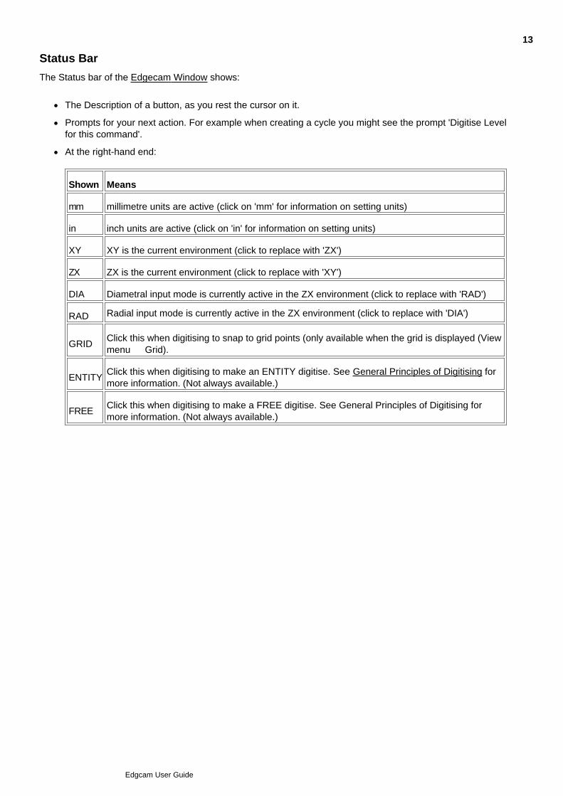
Status Bar
The Status bar of the Edgecam Window shows:
The Description of a button, as you rest the cursor on it.
Prompts for your next action. For example when creating a cycle you might see the prompt 'Digitise Levelfor this command'.
At the right-hand end:
Shown Means
mm millimetre units are active (click on 'mm' for information on setting units)
in inch units are active (click on 'in' for information on setting units)
XY XY is the current environment (click to replace with 'ZX')
ZX ZX is the current environment (click to replace with 'XY')
DIA Diametral input mode is currently active in the ZX environment (click to replace with 'RAD')
RAD Radial input mode is currently active in the ZX environment (click to replace with 'DIA')
GRIDClick this when digitising to snap to grid points (only available when the grid is displayed (Viewmenu Grid).
ENTITYClick this when digitising to make an ENTITY digitise. See General Principles of Digitising formore information. (Not always available.)
FREEClick this when digitising to make a FREE digitise. See General Principles of Digitising formore information. (Not always available.)
13
Edgcam User Guide

Buttons
There are command and menu buttons.
You click on a command button to perform or activate the command. You click on a menu button to expand themenu, to show the items within it.
Buttons can appear in toolbars. They can also appear in menus (so you can have a menu within anothermenu).
Some buttons are combined command and menu buttons.
Some buttons have a lasting effect. For example you start the Polyline command by clicking its button, and thecommand stays active until you de-activate it (by right-clicking for example). While the button is active, this isindicated by its appearance; by an orange background, for example.
You can:
create new buttons.
Opt for tooltips to be displayed when you rest the cursor on a button, showing the button's name.
Opt for the shortcut key of the button's command to be shown in the tooltip.
Opt for larger versions of buttons' images.
You can change the appearance of a button in these ways:
Display the button as text (the name of the command or menu), or an image, or both.
Customise the image. You can change to one of a pre-defined set of images, or create an imageyourself.
Reset to the default image.
14
Edgcam User Guide

Menus
A menu is a special type of button; it is an expandable lists of further buttons.
As an example of using a menu, you could click on the File menu to expand it and show its buttons. You couldthen click on the Open button to open a new part.
You can:
Change the way menus expand when you click on them.
Opt for drop shadows to appear around expanded menus.
Shortcut menu
There is also a Shortcut menu that provides a quick alternative to some of the commonly used buttons andpreference settings. The menu also features a list of recently used commands (at the bottom), that you can useto quickly repeat a command.
To display the Shortcut menu:
If you are not already using a command right-click in the Graphics area.
If you are already using a command, such as drawing a line, hold down the right mouse key rather thanclicking, until the menu appears (clicking will terminate the command).
You can:
Use Options menu Shortcut to set the delay before the menu opens, and also the number of recentlyused commands listed.
15
Edgcam User Guide

Graphics Area Shortcut Menu
Shortcut menus are lists of commands that appear when you right-click.
If you right-click in the Graphics Area you see the Graphics Area Shortcut Menu.
If you are performing an action; for example creating a line:
There is a short delay before the menu appears. If you release the mouse button before this, the actionterminates.
The command you select typically affects your action. For example, you can switch between Freedigitises and Entity digitises.
So that you can quickly repeat a command, there is a 'recently used' list of commands at the bottom of theGraphics Area Shortcut menu.
You can customise the Graphics Area Shortcut menu to:
Set the delay before the menu appears.
Set the maximum size of the recently used commands list.
16
Edgcam User Guide

Menu Bar
The Menu bar is a special toolbar. As a toolbar, you can dock and undock it, and customise it (for example youcould remove a menu or add a new menu).
Unlike the other toolbars however:
You cannot hide the Menu bar.
For menu buttons within the Menu bar there is more limited customisation available than for other menubuttons; you can only change the button's text.
It is re-set using a different method to other toolbars.
17
Edgcam User Guide

View Caption
In the View Caption there is an indication of the view orientation ('Top', 'Left' and so on), and of the zoommagnification factor.
You can right-click on the View Caption to display shortcut menu options for working with the view; you canchange its orientation and other properties for example.
18
Edgcam User Guide
Windows
Windows are sub-areas within the Edgecam window dedicated to a particular area of functionality.
Examples are:
The Features window which you use to work with found features.
The Sequences window, in which you work with your machining instructions.
You can:
Show and hide windows.
Auto-hide windows (this means the window collapses to a small marker at its docking point when youmove the cursor out of the window; you expand the window back to full size by moving the cursor overthe marker).
Move, dock and undock windows. Multiple windows can be docked to the same edge of the Graphicswindow. In this case:
The edge can be divided up into an area for each window.
Alternatively multiple windows can grouped into the same area, with tabs for switching betweenthem.
You choose between these alternatives by how you dock the window. If tabbed windows are auto-hidden,there is a small marker for each of the tabs.
Change the font. This is a Windows setting; refer to your Windows documentation for details.
19
Edgcam User Guide
Features Window
The Features Window of the overall Edgecam window is a central area for working with the loaded solids, andany features found in the solids.
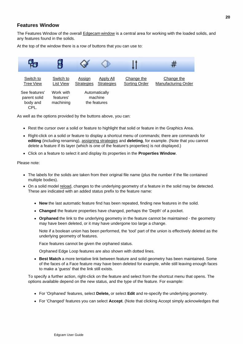
At the top of the window there is a row of buttons that you can use to:
Switch toTree View
Switch toList View
AssignStrategies
Apply AllStrategies
Change theSorting Order
Change theManufacturing Order
See features'parent solidbody and
CPL.
Work withfeatures'
machining
Automaticallymachine
the features
As well as the options provided by the buttons above, you can:
Rest the cursor over a solid or feature to highlight that solid or feature in the Graphics Area.
Right-click on a solid or feature to display a shortcut menu of commands; there are commands forediting (including renaming), assigning strategies and deleting, for example. (Note that you cannotdelete a feature if its layer (which is one of the feature's properties) is not displayed.)
Click on a feature to select it and display its properties in the Properties Window.
Please note:
The labels for the solids are taken from their original file name (plus the number if the file containedmultiple bodies).
On a solid model reload, changes to the underlying geometry of a feature in the solid may be detected.These are indicated with an added status prefix to the feature name:
New the last automatic feature find has been repeated, finding new features in the solid.
Changed the feature properties have changed, perhaps the 'Depth' of a pocket.
Orphaned the link to the underlying geometry in the feature cannot be maintained - the geometrymay have been deleted, or it may have undergone too large a change.
Note if a boolean union has been performed, the 'tool' part of the union is effectively deleted as theunderlying geometry of features.
Face features cannot be given the orphaned status.
Orphaned Edge Loop features are also shown with dotted lines.
Best Match a more tentative link between feature and solid geometry has been maintained. Someof the faces of a Face feature may have been deleted for example, while still leaving enough facesto make a 'guess' that the link still exists.
To specify a further action, right-click on the feature and select from the shortcut menu that opens. Theoptions available depend on the new status, and the type of the feature. For example:
For 'Orphaned' features, select Delete, or select Edit and re-specify the underlying geometry.
For 'Changed' features you can select Accept. (Note that clicking Accept simply acknowledges that
20
Edgcam User Guide

you have seen the indication. The machining based on the features may still need to be updated(this can happen automatically on a reload, according to your Regenerate Current Sequencepreference setting).)
You can use Accept on multiple selected features, or on solids or CPLs (accepts all their features).
If any modified features have not been accepted when you enter manufacture mode, a warning messagewill be displayed, and you will be prompted to complete the review process.
Features are listed by their entity number, which equates to their order of creation. A 'tapped hole' feature with a '?' against its name is not 'fully defined'; one or more or these parameters isnot set: Thread Units, Tap Diameter, Drill Size, Pitch/TPI, and Depth.
21
Edgcam User Guide
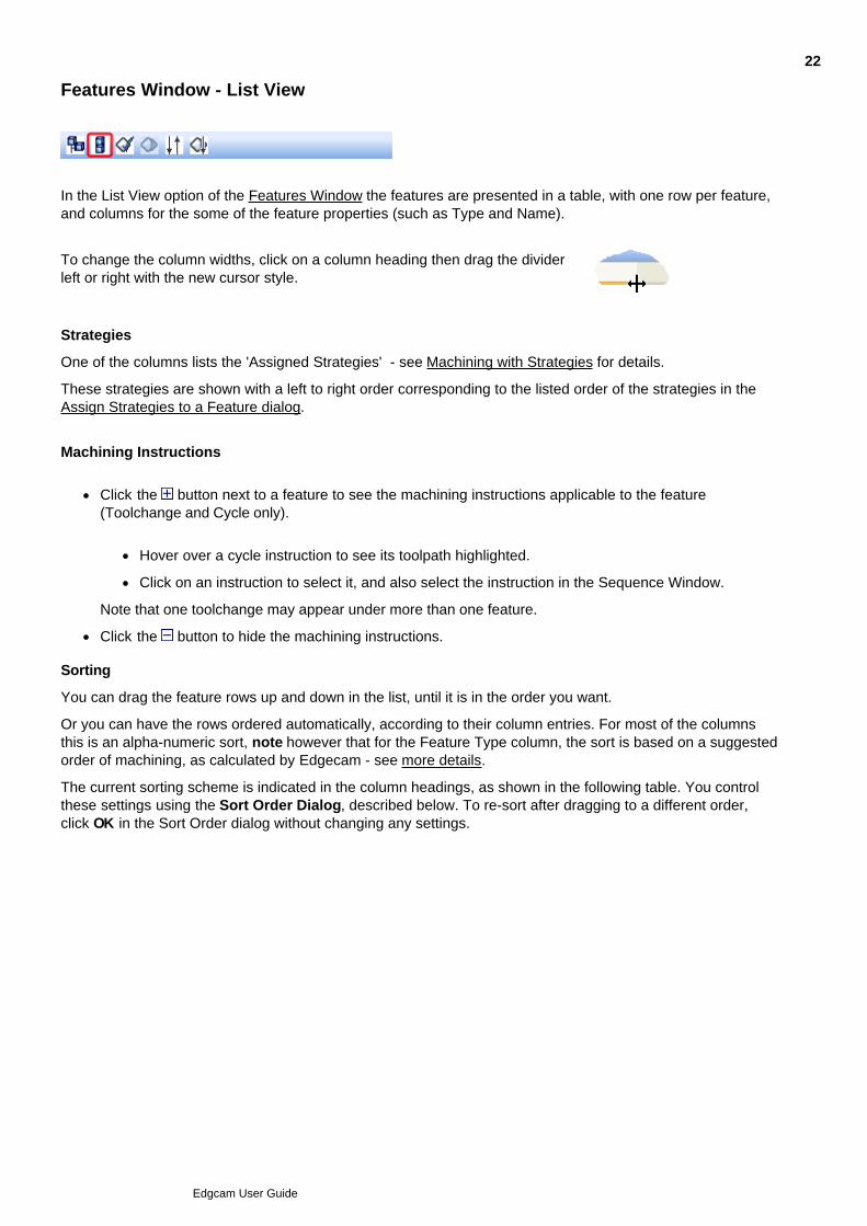
Features Window - List View
In the List View option of the Features Window the features are presented in a table, with one row per feature,and columns for the some of the feature properties (such as Type and Name).
To change the column widths, click on a column heading then drag the dividerleft or right with the new cursor style.
Strategies
One of the columns lists the 'Assigned Strategies' - see Machining with Strategies for details.
These strategies are shown with a left to right order corresponding to the listed order of the strategies in theAssign Strategies to a Feature dialog.
Machining Instructions
Click the button next to a feature to see the machining instructions applicable to the feature(Toolchange and Cycle only).
Hover over a cycle instruction to see its toolpath highlighted.
Click on an instruction to select it, and also select the instruction in the Sequence Window.
Note that one toolchange may appear under more than one feature.
Click the button to hide the machining instructions.
Sorting
You can drag the feature rows up and down in the list, until it is in the order you want.
Or you can have the rows ordered automatically, according to their column entries. For most of the columnsthis is an alpha-numeric sort, note however that for the Feature Type column, the sort is based on a suggestedorder of machining, as calculated by Edgecam - see more details.
The current sorting scheme is indicated in the column headings, as shown in the following table. You controlthese settings using the Sort Order Dialog, described below. To re-sort after dragging to a different order,click OK in the Sort Order dialog without changing any settings.
22
Edgcam User Guide
Priority (1) column - The list is first sorted according to the entries in this column.
Priority (2) column - If the (1) sort does not discriminate between several features (all the features in thesame CPL for example), then these features are sorted according to their (2)column entries.
Priority (3) column - If the (1) and (2) sorts do discriminate between several features, then thesefeatures are sorted according to their (3) column entries.
. .
and so on and so on
Note that a column might not have a Priority number - it may have been left blank inthe Sort Order dialog (see below).
- Indicates an ascending sort for the column ('a' above 'b', '1' above '2'). Click on thecolumn heading to switch to ' '.
(Note how this does not necessarily invert the whole list - only the ordering of thosefeatures which need this column to determine their order.)
- Indicates a descending sort for the column ('b' above 'a', '2' above '1'). Click on thecolumn heading to switch to ' '.
Sort Order dialog
To fully control the columns' Priority and Direction (Ascending/Descending) settings:
Click the button at the top of the Feature Window.1.
In the Feature Browser - Sort Order dialog that opens:
Click on the Priority or Direction column for a property to select it.
Click again and select from the list that appears.
Not all the columns need have a Priority number - columns left blank rank lower than any number.
If you assign the same Priority number to more than one column, the column furthest to the Left inthe table has the highest ranking.
2.
Click OK to close the dialog.
(Click OK without making any changes to re-sort the table to the current scheme, after dragging the rowsto a different order.)
3.
23
Edgcam User Guide
Features Window - Tree View
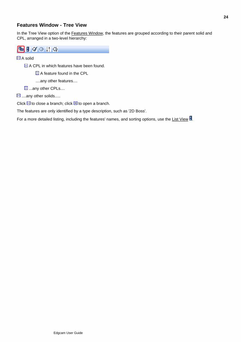
In the Tree View option of the Features Window, the features are grouped according to their parent solid andCPL, arranged in a two-level hierarchy:
A solid
A CPL in which features have been found.
A feature found in the CPL
....any other features....
...any other CPLs....
....any other solids.....
Click to close a branch; click to open a branch.
The features are only identified by a type description, such as '2D Boss'.
For a more detailed listing, including the features' names, and sorting options, use the List View .
24
Edgcam User Guide
Sequence Window
The Sequence Window shows sequences of machining instructions. It uses a 'tree' style similar to WindowsExplorer.
The instruction labels feature a sequence number and the type of the instruction (for example 'PocketOperation'). Toolchange instructions may also feature a Sort Priority number.
You can:
Right-click on an instruction to open a shortcut menu of commands to operate on that instruction, suchas the Edit command.
Right-click on the window background to open a shortcut menu of commands relating to the instructionsas a whole, such as Search, which searches all the instructions for text.
Re-arrange, edit and delete instructions.
Arrange instructions into various groupings.
Show or hide the layer showing a tool's toolpaths.
Opt for an instruction's toolpath to be highlighted when you rest the cursor on the instruction; use theOptions menu > Preferences > Toolpaths tab > Highlight Instructions option.
Side-by-Side mode
In Side-by-Side mode there is a separate tab for each sequence.
You can right-click on the tab title to display a shortcut list of menu options; for example you can choose Newto create a new sequence.
Click on a tab title to bring it to the front. Double-click on a tab title to select it as the active sequence (becomesmarked with a '*'.
To switch to Side-by-Side mode right-click in the window and click to check Side by Side. Check the SingleScroll Bar option to scroll both window panes at the same time.
Twin Turrets
In the turning environment you can use the 'Side by Side' option for viewing instructions for twin turrets. Eachturret appears as a separately titled sequence in one tab.
Click on a title to select it. Double-click to select the turret as the active turret (becomes marked with a '*').
The synchronisation commands are displayed in the window in both turrets.
On each turret, the Spindle column shows the currently active spindle (main or sub), with the green backgroundindicating spindle priority.
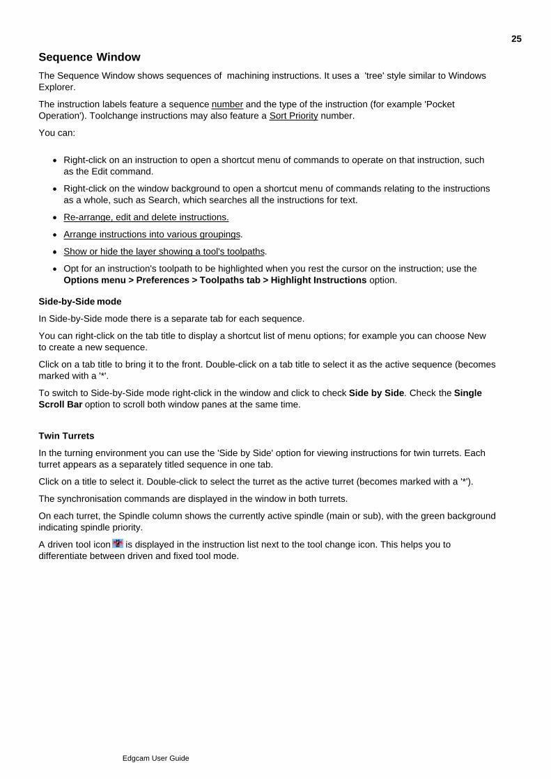
A driven tool icon is displayed in the instruction list next to the tool change icon. This helps you todifferentiate between driven and fixed tool mode.
25
Edgcam User Guide
Grouping Instructions
Folders can appear in the Sequence Window that contain instructions; these are 'instruction groups':
Group Closed Group Open
You work with groups in the same way as you work with individual instructions; for example you can delete agroup, which deletes all the instructions within it. In this respect groups are similar to Windows Explorer foldersand their files. They are similar in many other respects; for example you can rename groups, open and closethem, and move and copy them.
The sequence and the instructions within a folder are not affected by being in the folder. For example you caninsert into the folder's sequence in the normal way.
You can work with a group by right-clicking on it and selecting a command from the shortcut menu.
To group instructions, right-click in the Sequence Window and in the shortcut menu click the appropriateGroup command. For example Group Group by Tool.
You can also 'Group by Index' and 'Group by Synchronisation'. Only one grouping can apply at any onetime, so for example using Group by Tool will undo the Group by Index.
Note:
Do not confuse this way of grouping with the groupings you create with the Instructions Operationcommand.
The groupings group together instructions between events in the sequence, so 'Group by Tool' is moreaccurately described as 'Group by Toolchange' (the toolchange instruction is always the first in thegroup).
Grouped instructions are displayed in the Time Line in the same way as Operations.
26
Edgcam User Guide

Showing and Hiding Toolchange Layers
You can show or hide the layer containing the toolpaths associated with a toolchange instruction.
In the Sequence Window right-click on the toolchange instruction.
If the instruction is in a 'group by tool' instruction group, you can right-click on the group (folder).
1.
In the subsequent shortcut menu click Display Layer to show the layer, click Display Layer to hide thelayer.
2.
Note that the Layers window shows the effects of your change.
27
Edgcam User Guide
Deleted Geometry Checking
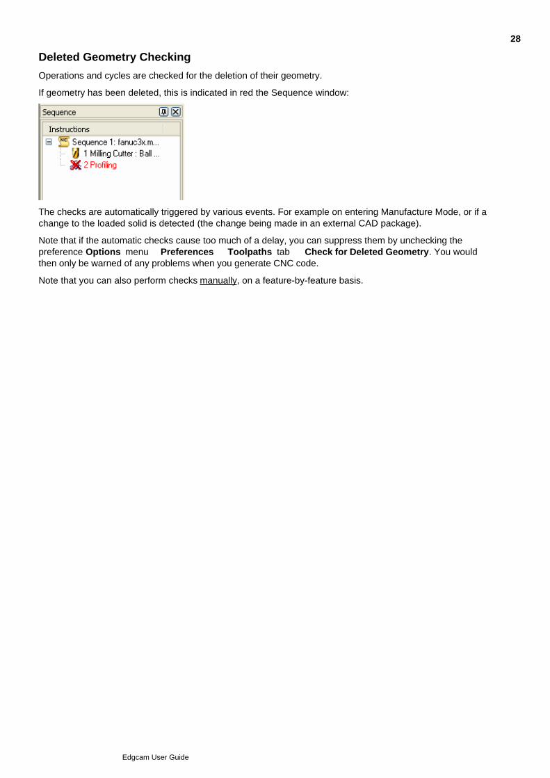
Operations and cycles are checked for the deletion of their geometry.
If geometry has been deleted, this is indicated in red the Sequence window:
The checks are automatically triggered by various events. For example on entering Manufacture Mode, or if achange to the loaded solid is detected (the change being made in an external CAD package).
Note that if the automatic checks cause too much of a delay, you can suppress them by unchecking thepreference Options menu Preferences Toolpaths tab Check for Deleted Geometry. You wouldthen only be warned of any problems when you generate CNC code.
Note that you can also perform checks manually, on a feature-by-feature basis.
28
Edgcam User Guide

Searching for Text in the Sequence Window
You can search for any text that appears in the Sequence window; in the names of tools, cycles andoperations, for example:
Click anywhere in the Sequence window and press Ctrl-f. Alternatively right-click in the window and inthe shortcut menu click Search.
1.
Use the subsequent Find dialog to search for your text.2.
As a shortcut way to search, you can press F3. This either opens the Find dialog so you can specify yoursearch text, or it finds the next instance of your text if it is already specified.
If you use 'Mark' to highlight the found text, you can clear this as follows:
Click to select an instruction in the Sequence window and in the shortcut menu click Highlight Remove all or Highlight Remove selected.
29
Edgcam User Guide
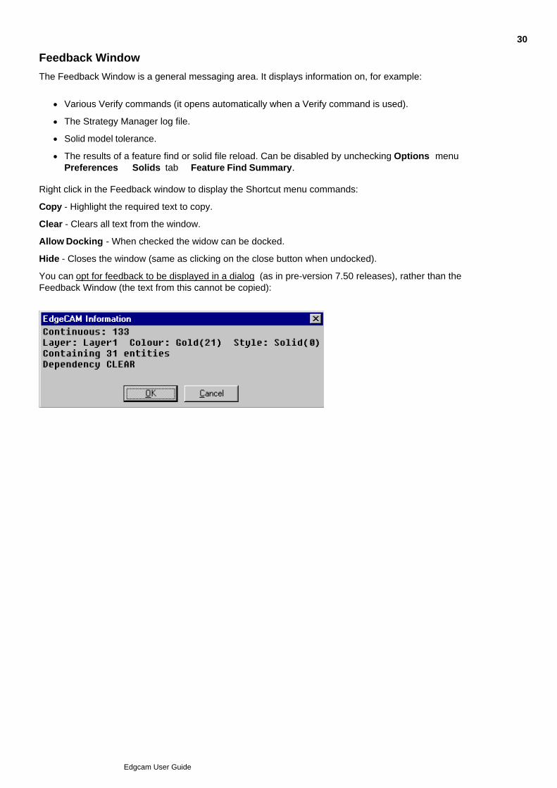
Feedback Window
The Feedback Window is a general messaging area. It displays information on, for example:
Various Verify commands (it opens automatically when a Verify command is used).
The Strategy Manager log file.
Solid model tolerance.
The results of a feature find or solid file reload. Can be disabled by unchecking Options menu Preferences Solids tab Feature Find Summary.
Right click in the Feedback window to display the Shortcut menu commands:
Copy - Highlight the required text to copy.
Clear - Clears all text from the window.
Allow Docking - When checked the widow can be docked.
Hide - Closes the window (same as clicking on the close button when undocked).
You can opt for feedback to be displayed in a dialog (as in pre-version 7.50 releases), rather than theFeedback Window (the text from this cannot be copied):
30
Edgcam User Guide
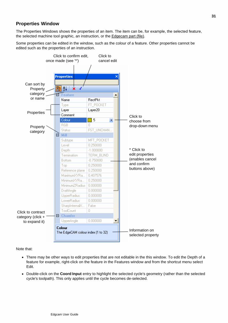
Properties Window
The Properties Windows shows the properties of an item. The item can be, for example, the selected feature,the selected machine tool graphic, an instruction, or the Edgecam part (file).
Some properties can be edited in the window, such as the colour of a feature. Other properties cannot beedited such as the properties of an instruction.
Click to confirm edit,once made (see '*')
Click tocancel edit
Can sort byPropertycategoryor name
Properties
Propertycategory
Click to contractcategory (click +
to expand it)
Click tochoose fromdrop-down menu
* Click toedit properties(enables canceland confirmbuttons above)
Information onselected property
Note that:
There may be other ways to edit properties that are not editable in the this window. To edit the Depth of afeature for example, right-click on the feature in the Features window and from the shortcut menu selectEdit.
Double-click on the Coord Input entry to highlight the selected cycle's geometry (rather than the selectedcycle's toolpath). This only applies until the cycle becomes de-selected.
31
Edgcam User Guide

There are more details on features' Level, Depth, Bottom and Top properties.
You can use the left and right arrow keys to step through the properties.
Where a property has drop-down setting options, you can use the space bar to step through them.
You can make multiple edits then confirm or cancel them all with a single click of the confirm or cancelbutton.
32
Edgcam User Guide
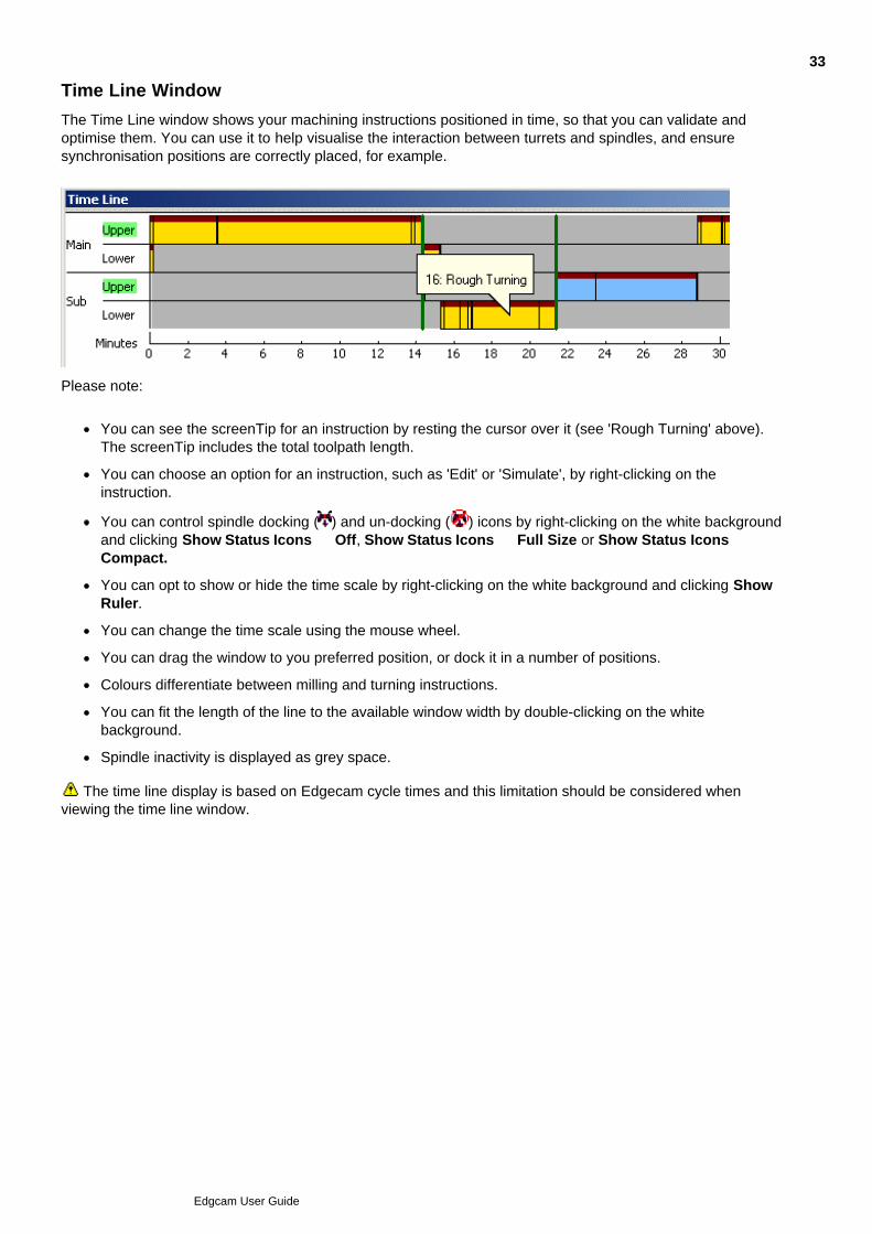
Time Line Window
The Time Line window shows your machining instructions positioned in time, so that you can validate andoptimise them. You can use it to help visualise the interaction between turrets and spindles, and ensuresynchronisation positions are correctly placed, for example.
Please note:
You can see the screenTip for an instruction by resting the cursor over it (see 'Rough Turning' above).The screenTip includes the total toolpath length.
You can choose an option for an instruction, such as 'Edit' or 'Simulate', by right-clicking on theinstruction.
You can control spindle docking ( ) and un-docking ( ) icons by right-clicking on the white backgroundand clicking Show Status Icons Off, Show Status Icons Full Size or Show Status Icons Compact.
You can opt to show or hide the time scale by right-clicking on the white background and clicking ShowRuler.
You can change the time scale using the mouse wheel.
You can drag the window to you preferred position, or dock it in a number of positions.
Colours differentiate between milling and turning instructions.
You can fit the length of the line to the available window width by double-clicking on the whitebackground.
Spindle inactivity is displayed as grey space.
The time line display is based on Edgecam cycle times and this limitation should be considered whenviewing the time line window.
33
Edgcam User Guide
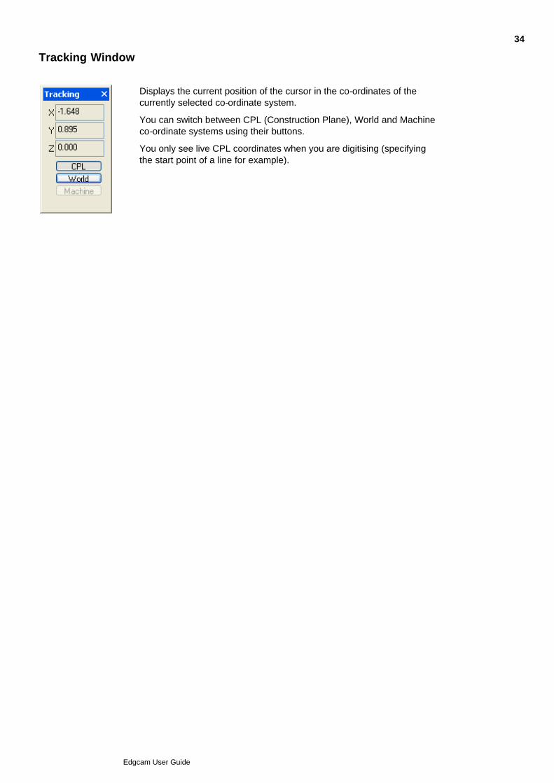
Tracking Window
Displays the current position of the cursor in the co-ordinates of thecurrently selected co-ordinate system.
You can switch between CPL (Construction Plane), World and Machineco-ordinate systems using their buttons.
You only see live CPL coordinates when you are digitising (specifyingthe start point of a line for example).
34
Edgcam User Guide
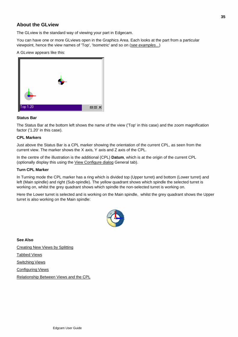
About the GLview
The GLview is the standard way of viewing your part in Edgecam.
You can have one or more GLviews open in the Graphics Area. Each looks at the part from a particularviewpoint, hence the view names of 'Top', 'Isometric' and so on (see examples...)
A GLview appears like this:
Status Bar
The Status Bar at the bottom left shows the name of the view ('Top' in this case) and the zoom magnificationfactor ('1.20' in this case).
CPL Markers
Just above the Status Bar is a CPL marker showing the orientation of the current CPL, as seen from thecurrent view. The marker shows the X axis, Y axis and Z axis of the CPL.
In the centre of the illustration is the additional (CPL) Datum, which is at the origin of the current CPL(optionally display this using the View Configure dialog General tab).
Turn CPL Marker
In Turning mode the CPL marker has a ring which is divided top (Upper turret) and bottom (Lower turret) andleft (Main spindle) and right (Sub-spindle). The yellow quadrant shows which spindle the selected turret isworking on, whilst the grey quadrant shows which spindle the non-selected turret is working on.
Here the Lower turret is selected and is working on the Main spindle, whilst the grey quadrant shows the Upperturret is also working on the Main spindle:
See Also
Creating New Views by Splitting
Tabbed Views
Switching Views
Configuring Views
Relationship Between Views and the CPL
35
Edgcam User Guide
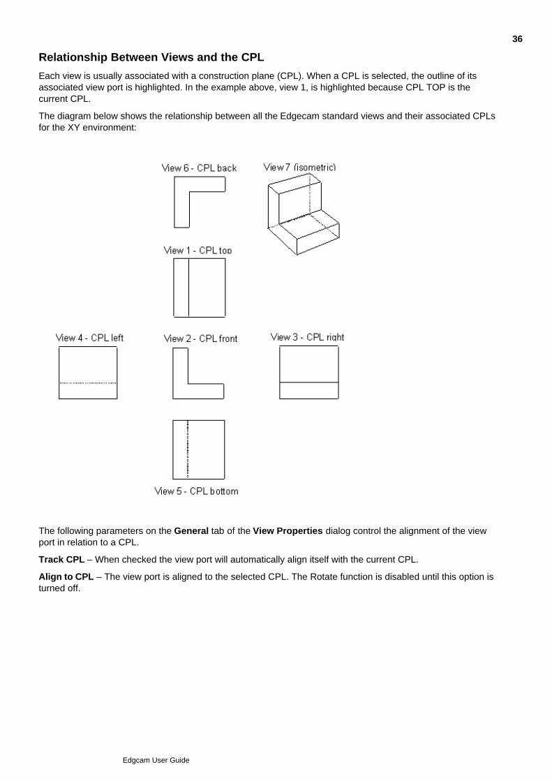
Relationship Between Views and the CPL
Each view is usually associated with a construction plane (CPL). When a CPL is selected, the outline of itsassociated view port is highlighted. In the example above, view 1, is highlighted because CPL TOP is thecurrent CPL.
The diagram below shows the relationship between all the Edgecam standard views and their associated CPLsfor the XY environment:
The following parameters on the General tab of the View Properties dialog control the alignment of the viewport in relation to a CPL.
Track CPL – When checked the view port will automatically align itself with the current CPL.
Align to CPL – The view port is aligned to the selected CPL. The Rotate function is disabled until this option isturned off.
36
Edgcam User Guide

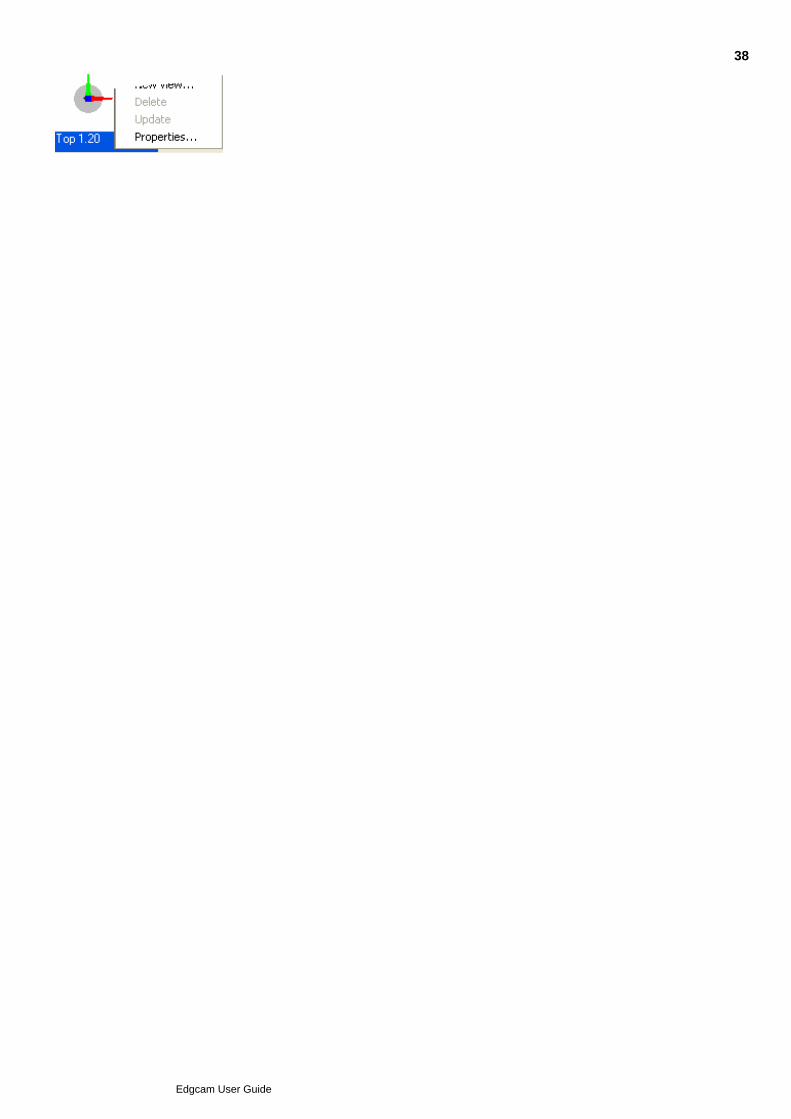
Switching Views
To change views right-click on the View Caption and select the new view fromthe shortcut menu.
For a quick method of changing between alternate view properties within a single view see Tabbed Views.
37
Edgcam User Guide
38
Edgcam User Guide
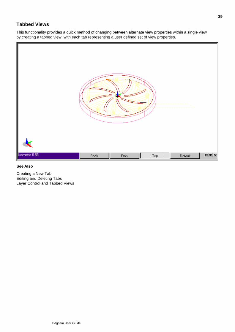
Tabbed Views
This functionality provides a quick method of changing between alternate view properties within a single viewby creating a tabbed view, with each tab representing a user defined set of view properties.
See Also
Creating a New TabEditing and Deleting TabsLayer Control and Tabbed Views
39
Edgcam User Guide
Creating a New Tab
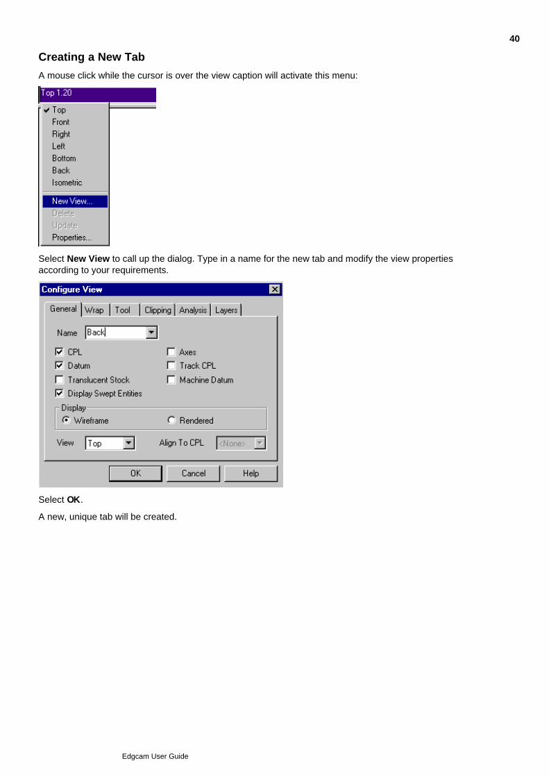
A mouse click while the cursor is over the view caption will activate this menu:
Select New View to call up the dialog. Type in a name for the new tab and modify the view propertiesaccording to your requirements.
Select OK.
A new, unique tab will be created.
40
Edgcam User Guide
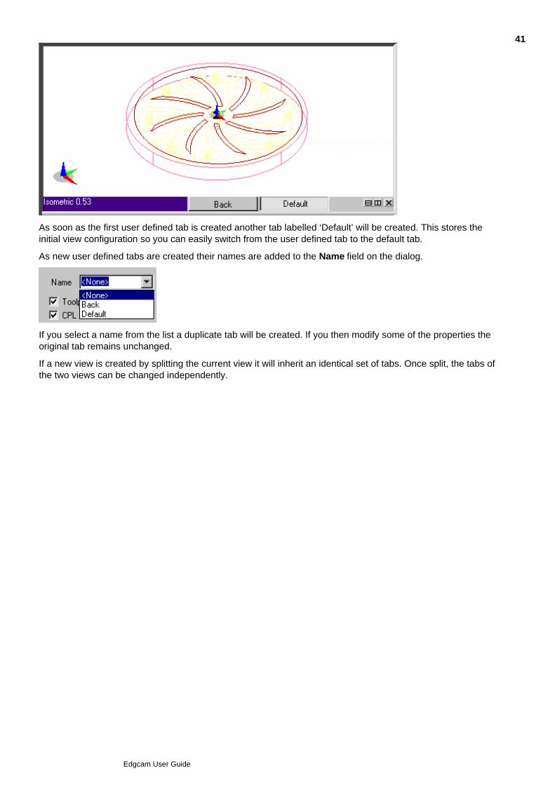
As soon as the first user defined tab is created another tab labelled ‘Default’ will be created. This stores theinitial view configuration so you can easily switch from the user defined tab to the default tab.
As new user defined tabs are created their names are added to the Name field on the dialog.
If you select a name from the list a duplicate tab will be created. If you then modify some of the properties theoriginal tab remains unchanged.
If a new view is created by splitting the current view it will inherit an identical set of tabs. Once split, the tabs ofthe two views can be changed independently.
41
Edgcam User Guide
Editing and Deleting Tabs
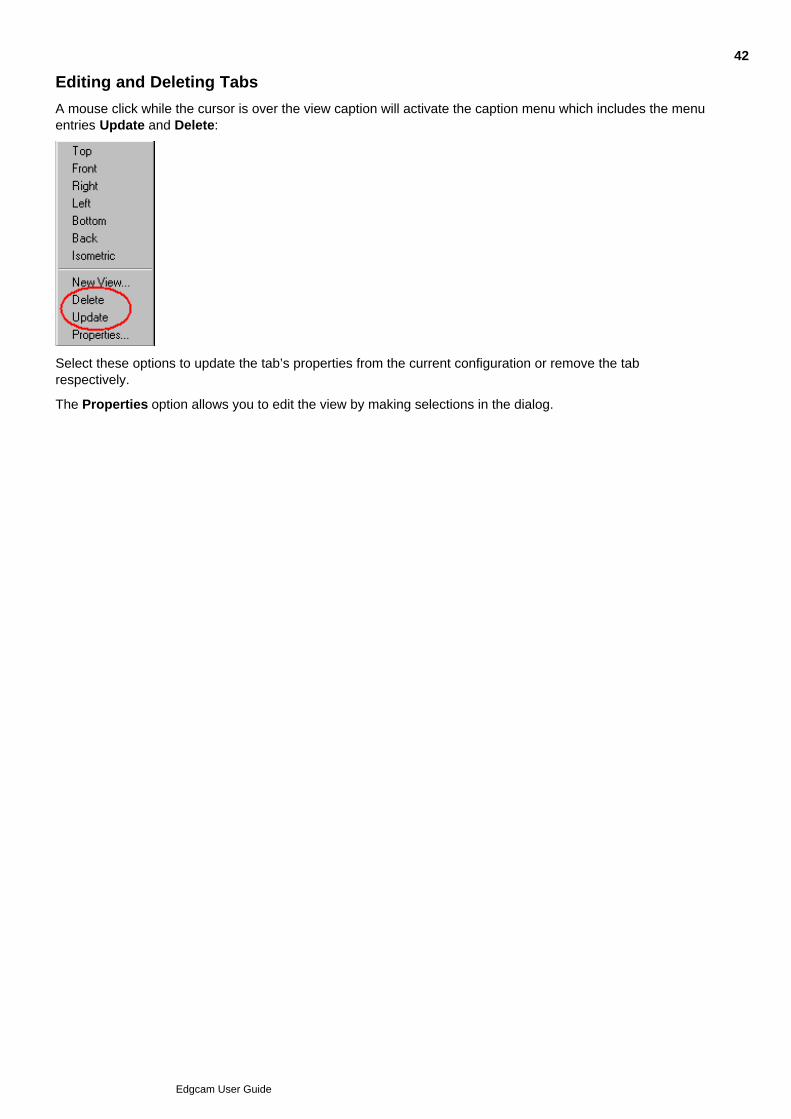
A mouse click while the cursor is over the view caption will activate the caption menu which includes the menuentries Update and Delete:
Select these options to update the tab’s properties from the current configuration or remove the tabrespectively.
The Properties option allows you to edit the view by making selections in the dialog.
42
Edgcam User Guide
Layer Control and Tabbed Views
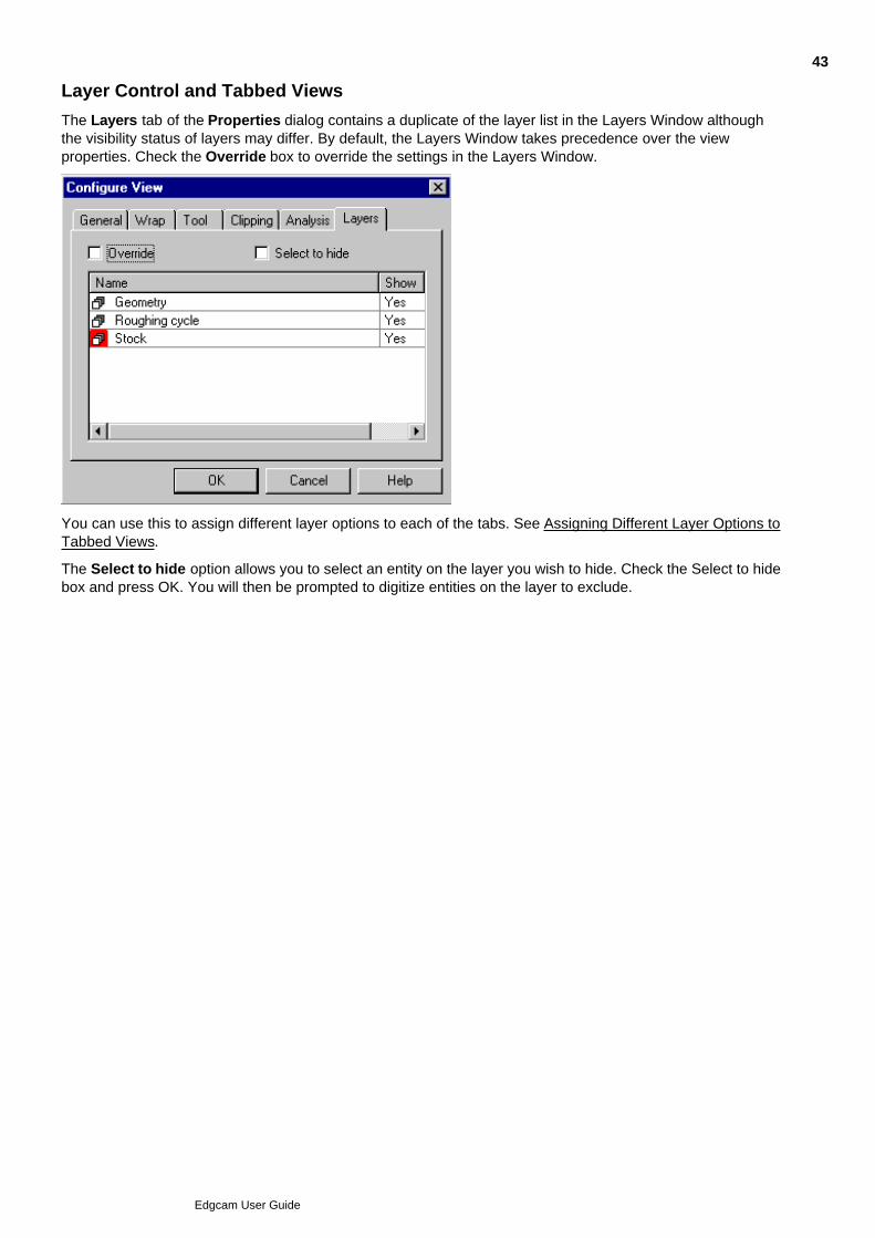
The Layers tab of the Properties dialog contains a duplicate of the layer list in the Layers Window althoughthe visibility status of layers may differ. By default, the Layers Window takes precedence over the viewproperties. Check the Override box to override the settings in the Layers Window.
You can use this to assign different layer options to each of the tabs. See Assigning Different Layer Options toTabbed Views.
The Select to hide option allows you to select an entity on the layer you wish to hide. Check the Select to hidebox and press OK. You will then be prompted to digitize entities on the layer to exclude.
43
Edgcam User Guide
Assigning Different Layer Options to Tabbed Views
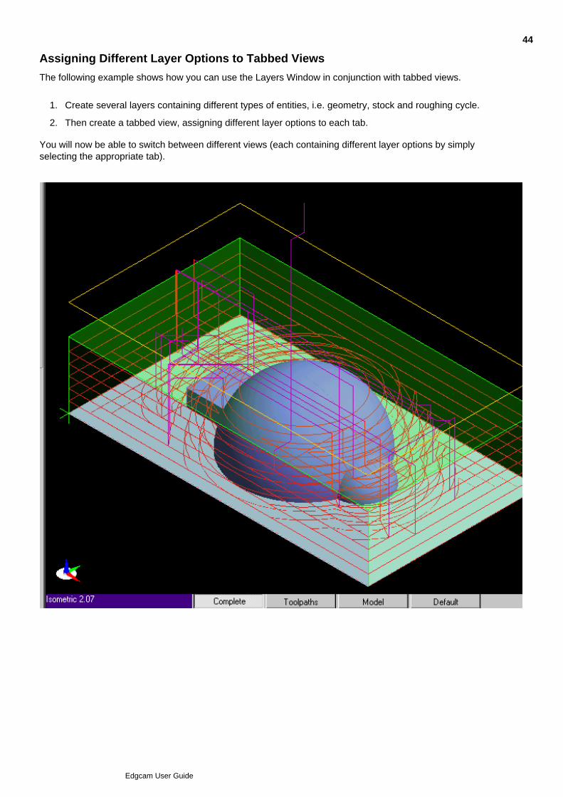
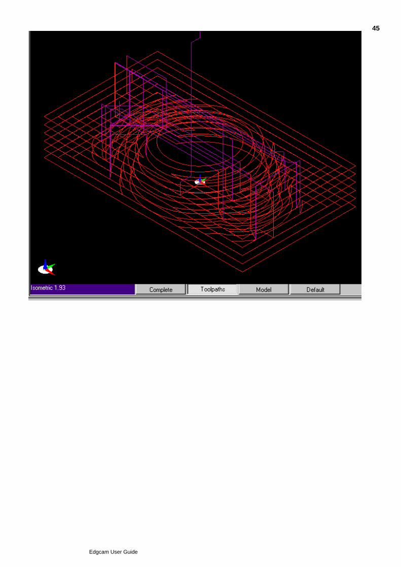
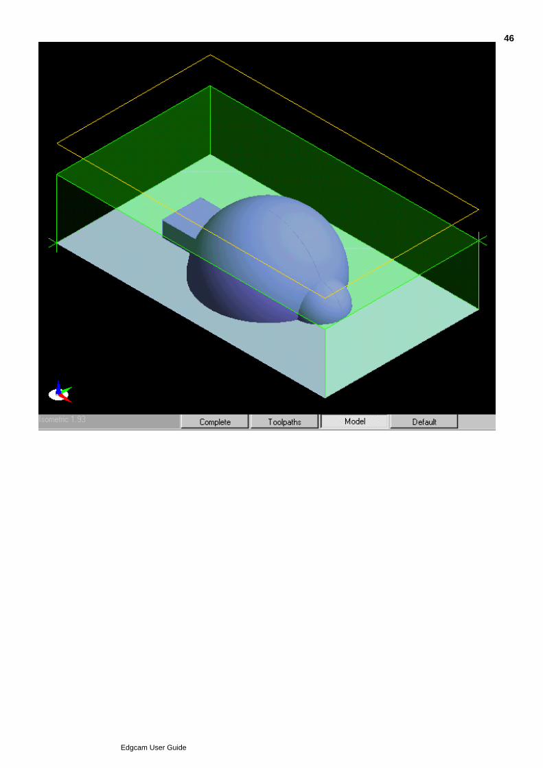
The following example shows how you can use the Layers Window in conjunction with tabbed views.
Create several layers containing different types of entities, i.e. geometry, stock and roughing cycle.1.
Then create a tabbed view, assigning different layer options to each tab.2.
You will now be able to switch between different views (each containing different layer options by simplyselecting the appropriate tab).
44
Edgcam User Guide
45
Edgcam User Guide
46
Edgcam User Guide

Standard Views
There are two sets of standard views in Edgecam; one for each environment. They are shown in the followingtable:
XY Environment ZX Environment
Top Turn
Front Inverse Turn
Right Radial
Left Axial
Bottom Isometric Turn
Back Unwrap
Isometric Wrap
47
Edgcam User Guide
Creating New Views by Splitting
Splitting the screen by using icons
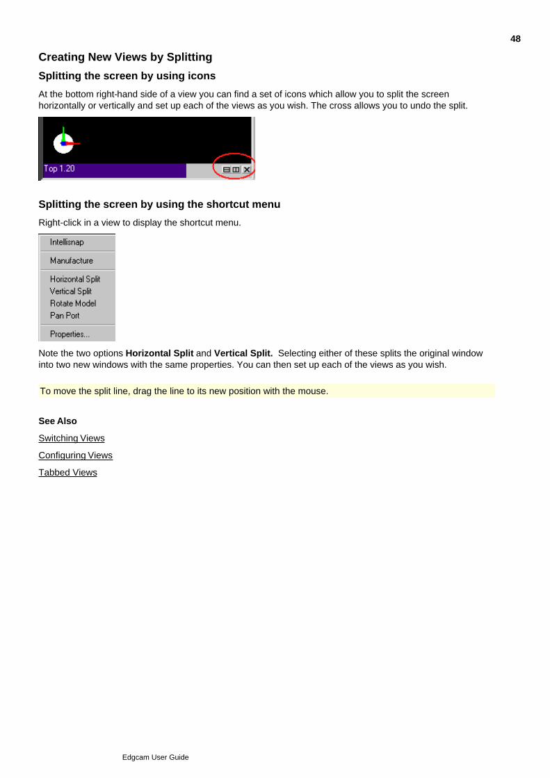
At the bottom right-hand side of a view you can find a set of icons which allow you to split the screenhorizontally or vertically and set up each of the views as you wish. The cross allows you to undo the split.
Splitting the screen by using the shortcut menu
Right-click in a view to display the shortcut menu.
Note the two options Horizontal Split and Vertical Split. Selecting either of these splits the original windowinto two new windows with the same properties. You can then set up each of the views as you wish.
To move the split line, drag the line to its new position with the mouse.
See Also
Switching Views
Configuring Views
Tabbed Views
48
Edgcam User Guide

Rotating and Spinning Views
There are two options for rotating the view:
In the Display toolbar click Rotate to activate it. Then in the Graphics Area hold down the left mousebutton and drag around to rotate the view. Right-click or click Rotate again to de-activate the rotation.
Alternatively hold down the right-hand mouse button and drag (note how Rotate in the Display toolbarindicates that it is active while the button is held down).
To lock the rotation so that it is only around an axis parallel to the X, Y or Z Axis, hold down the 'X', 'Y'or 'Z' key while rotating.
Use Spin in the same way as Rotate (except you cannot right-button drag). Spin is similar to Rotate,but the speed of rotation on releasing the mouse button is maintained. Release the button while themouse is still moving for an indefinite rotation (while Spin is active).
As standard, the Spin command is not present in the User Interface; you will need to add it to atoolbar or menu.The command is in the GL View category.
The rotation will occur about the centre of the model.
To rotate the model about a point, position the cursor on the desired spot on the model and select this pointas centre of rotation with a right-hand mouse click while holding down the Ctrl key. The selected point is movedto the screen centre. You can then use either method described above to rotate the model about the selectedpoint.
The Zoom Extents command will reset the centre back to the middle of the model.
49
Edgcam User Guide

Deleting Views
Right click in a view window to display the shortcut menu.1.
Select the Close Window option to delete the currently active view.2.
50
Edgcam User Guide

Panning Views
From the Display toolbar, this button lets you drag the view around:
Note that the cursor changes to the same shape to show that dynamic panning is active.
If your mouse has a wheel you can also pan by holding down the wheel and moving the mouse.
51
Edgcam User Guide
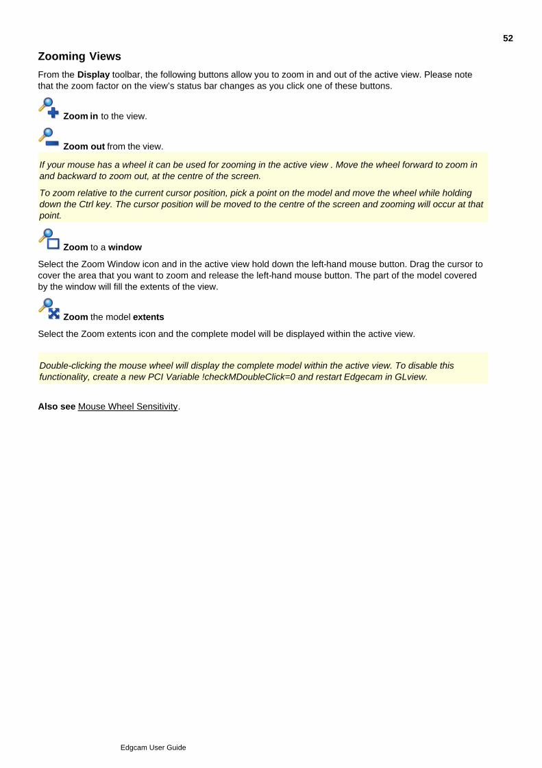
Zooming Views
From the Display toolbar, the following buttons allow you to zoom in and out of the active view. Please notethat the zoom factor on the view’s status bar changes as you click one of these buttons.
Zoom in to the view.
Zoom out from the view.
If your mouse has a wheel it can be used for zooming in the active view . Move the wheel forward to zoom inand backward to zoom out, at the centre of the screen.
To zoom relative to the current cursor position, pick a point on the model and move the wheel while holdingdown the Ctrl key. The cursor position will be moved to the centre of the screen and zooming will occur at thatpoint.
Zoom to a window
Select the Zoom Window icon and in the active view hold down the left-hand mouse button. Drag the cursor tocover the area that you want to zoom and release the left-hand mouse button. The part of the model coveredby the window will fill the extents of the view.
Zoom the model extents
Select the Zoom extents icon and the complete model will be displayed within the active view.
Double-clicking the mouse wheel will display the complete model within the active view. To disable thisfunctionality, create a new PCI Variable !checkMDoubleClick=0 and restart Edgecam in GLview.
Also see Mouse Wheel Sensitivity.
52
Edgcam User Guide
Clipping Views
Clipping allows you to restrict the display of entities to a specified level. This is particularly useful when workingwith complex 3D wireframe models, in a multiplane milling environment and in solid turning.
Clipping planes will be generated relative to the current CPL.
When multiple views are displayed, it is possible to apply different clipping parameters to each view.
To use clipping in GLview
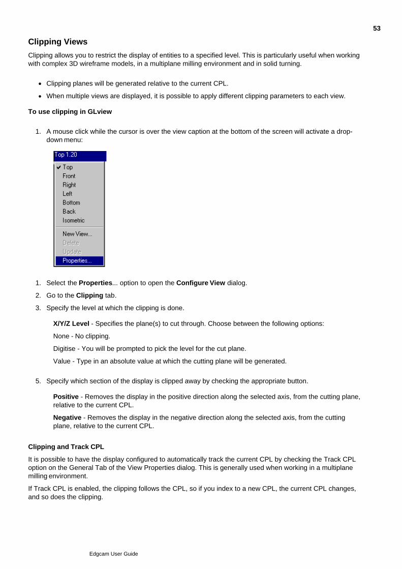
A mouse click while the cursor is over the view caption at the bottom of the screen will activate a drop-down menu:
1.
Select the Properties... option to open the Configure View dialog.1.
Go to the Clipping tab.2.
Specify the level at which the clipping is done.3.
X/Y/Z Level - Specifies the plane(s) to cut through. Choose between the following options:
None - No clipping.
Digitise - You will be prompted to pick the level for the cut plane.
Value - Type in an absolute value at which the cutting plane will be generated.
Specify which section of the display is clipped away by checking the appropriate button.5.
Positive - Removes the display in the positive direction along the selected axis, from the cutting plane,relative to the current CPL.
Negative - Removes the display in the negative direction along the selected axis, from the cuttingplane, relative to the current CPL.
Clipping and Track CPL
It is possible to have the display configured to automatically track the current CPL by checking the Track CPLoption on the General Tab of the View Properties dialog. This is generally used when working in a multiplanemilling environment.
If Track CPL is enabled, the clipping follows the CPL, so if you index to a new CPL, the current CPL changes,and so does the clipping.
53
Edgcam User Guide

Customising your Working Environment
There are many ways you can customise the Edgecam working environment so that it best supports the wayyou want to work. For example you can hide toolbars that you seldom use, to simplify the Edgecam Window.
All the information in this help on customising Edgecam is grouped into the ‘Customising Edgecam’ book in thetable of contents.
Note: When customising Edgecam your changes only apply under certain conditions; that is you should beaware of what the active Profile is. Profiles are how Edgecam can adapt itself to different situations; whetheryou are milling or turning for example. See Profiles and Configurations for more information.
54
Edgcam User Guide

Setting Preferences
Use Options menu Preferences to set preferences such as the units for the part and thetolerances.
Here are details on the preferences (you can also access this help by clicking the Help button in thePreferences dialog):
55
Edgcam User Guide
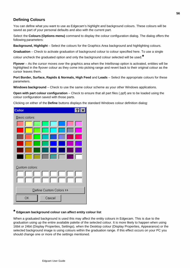
Defining Colours
You can define what you want to use as Edgecam’s highlight and background colours. These colours will besaved as part of your personal defaults and also with the current part.
Select the Colours (Options menu) command to display the colour configuration dialog. The dialog offers thefollowing parameters:
Background, Highlight – Select the colours for the Graphics Area background and highlighting colours.
Graduation – Check to activate graduation of background colour to colour specified here. To use a single
colour uncheck the graduated option and only the background colour selected will be used.*Flyover – As the cursor moves over the graphics area when the Intellisnap option is activated, entities will behighlighted in the flyover colour as they come into picking range and revert back to their original colour as thecursor leaves them.
Port Border, Surface, Rapids & Normals, High Feed and Leads – Select the appropriate colours for theseparameters.
Windows background – Check to use the same colour scheme as your other Windows applications.
Open with part colour configuration – Check to ensure that all part files (.ppf) are to be loaded using thecolour configuration saved with those parts.
Clicking on either of the Define buttons displays the standard Windows colour definition dialog:
* Edgecam background colour can affect entity colour list
When a graduated background is used this may affect the entity colours in Edgecam. This is due to thegraduation using up the entire available palette of the selected colour. It is more likely to happen when using16bit or 24bit (Display Properties, Settings), when the Desktop colour (Display Properties, Appearance) or theselected background image is using colours within the graduation range. If this effect occurs on your PC youshould change one or more of the settings mentioned.
56
Edgcam User Guide
Profiles and Configurations
You can change the configuration of Edgecam to suit the way you work; you can hide toolbars that you seldomuse for example.
Edgecam configurations are stored so you don't need to re-configure for each work session. There are anumber of stored configurations, in these files:
default.config This is installed with Edgecam to provide a 'get you started' configuration.
user.config This automatically saves your configuration changes for future Edgecam sessions, onclosing Edgecam.
your_name.config You can save a useful configuration under a name of your choice. You can then makefurther configuration changes as circumstances change, knowing that you can returnto your saved configuration by restoring it. You can save any number of configurationsto suit different situations.
There are several sets of these configs, each set is contained in a 'Profile'....
Automatic configuration selection - Profiles
Profiles are how the Edgecam configuration automatically changes to suit the environment (for example the Millor Turn environment).
There is a profile for each environment, and each profile contains a user.config and a default.config (in additionto any configurations you have saved yourself).
When the environment changes, such as when you are in turning and you open a mill part, the profile for thenew environment automatically becomes the 'active' profile, and its user.config is restored.
Edgecam is now adapted to the new environment and the newly-restored user.config is where yourconfiguration changes are saved (on closing Edgecam).
Manual configuration selection
If the automatically restored configuration is not suitable, you can restore another configuration. You canrestore one of your saved configurations, or default.config to get back to a basic starting point. (You can alsosave configurations of individual toolbars and menus.) You will not need to repeat the restore the next time youuse Edgecam, as the restored configuration will be updated into user.config on closing the session.
You can also restore a user.config to get back to the configuration at the start of the Edgecam session; right-click on any menu and select Profiles A profile User.Config.
Note that your configuration changes since starting Edgecam will be lost on restoring a configuration (asuser.config is only updated on closing), unless you first save or update.
Restoring a configuration activates its profile, and this profile remains active until the environment changes (asdescribed above), or you restore a configuration from another profile.
Suppressing automatic selections - Generic profile
If you don't want the configuration to change on switching environments, you can restore one of theconfigurations from the Generic profile.
The Generic profile remains active until you restore a configuration from another profile; it doesn't de-activateon environment changes.
You can save your own configurations into the Generic profile.
57
Edgcam User Guide

Design and Manufacture Mode configuration
Each configuration is split into Design mode and Manufacture mode parts, so you see different toolbars in thetwo modes for example.
This does mean however that you might need to repeat your configuration change in each mode. For exampleif you change a shortcut key assignment, you will need to make the assignment again on switching modes.
Files of .dft type
Note that you should not confuse '.config' files with '.dft' files, which store 'system' type settings such astolerances and units.
58
Edgcam User Guide

Working with Configurations
At any time you can restore a configuration from any profile.
Right-click on any toolbar.1.
In the subsequent shortcut menu click Profiles a profile a configuration. For example clickProfiles Mill user.config.
Note that your restored configuration remains in place until there is an environment switch (such as whenyou are in milling and open a turn part) when the user.config is automatically restored from the newenvironment's profile. (That is unless your restored configuration is from the Generic profile; this remainsin place until you manually restore a configuration from another profile.)
The 'active profile' is the profile from which a configuration was last restored, this is indicated by a checkmark in the Profiles list.
2.
Alternatively, you can work with configurations (including saving and restoring) in the Customise dialog:
Right-click on any toolbar.1.
In the subsequent shortcut menu click Customise.2.
In the Customise dialog that opens, click the Configurations tab title to switch to it.3.
You can now work with the configurations in the tab. Here is the tab's help, for information:
59
Edgcam User Guide

Configuration File Notes
Permissions
If non-Administrators are to use an Edgecam installation, we recommend that:
After installation, the Administrator does not start Edgecam until a non-Adminstrator has used it.
Or that the user.config files are deleted before the Administrator logs off.
This is because if user.config files are created under an Administrator account, they are locked out to non-Adminstrators, so configuration changes would not automatically be saved.
(User.config files are not installed; they are created by copying from default.config whenever Edgecam startsand finds them not present.)
Licencing
If you frequently change licences we recommend that you save a configuration file for each licence, and restorethis with the licence.
This is because the User Interface facilities lost when you remove a licence are remembered in the 'user.config'files, so they are not automatically restored when you restore the licence.
Multiple users
When the same installation is to be used by multiple users, we recommend that:
All the users have the same permissions.
All users save their configuration under a unique name. Each user can then restore and work within theirown independent configuration.
60
Edgcam User Guide
Saving and Restoring Defaults
Two sets of defaults are delivered with Edgecam – one for imperial measurements, the other for metric.However, these default sets include a lot more information than the units to be used, such as the port setupand display and system tolerances.
You can select a set of defaults to use and create new defaults using the commands in the Options menu.You can update these default sets or create new default sets.
Creating New Defaults
The New Defaults command opens the usual Select File dialog box in which you can select a name or type ina new file name.
Name - Specifies the default file name.
Please note that default files (.dft) are always saved to the \cam\support directory in your Edgecaminstallation.
Selecting Existing Defaults
The Select Defaults (Options menu) command allows you to select an existing default file. This dialog box isdisplayed:
Load on entry – This parameter allows you to choose how a specified default file is loaded for the part.Choose from:
No change – The default file specified under Name is loaded, although this will not change the defaults loadedwith the part when you next load the part.
Selected File – This uses the file specified under Name.
None – No default file is loaded with the part.
61
Edgcam User Guide

Retaining Input Values
Edgecam also uses several modal defaults concerned with system variables.
These variables, such as file names, always offer the last value you used as the default value the next time youperform the same operation. These values are saved when you finish using Edgecam and reloaded for the nextsession. They are independent of parts and are not part of the defaults explained under Saving and RestoringDefaults.
Other modal defaults simply reflect your preferences, such as the colour, style and layer. These are not savedwith the part, nor do they form part of the default files, but they are reloaded each time you start Edgecam.
62
Edgcam User Guide

Showing and Hiding Windows
If you cannot see a window:
The window may be auto-hidden; find the window's labelled marker at an edge of the Edgecam windowand rest the cursor on it. The window will appear.
If you cannot see a marker or the window, you need to open the window:
Right-click on the title bar at the top of any window, or right-click on any toolbar.1.
In the subsequent shortcut menu rest the cursor on Windows .2.
In the subsequent list of windows click on an un-checked window to open and show it, click on a checkedwindow to hide it.
Note that in this list of windows there is a shortcut key combination displayed against each window. Youcan use the shortcut keys to quickly switch the window on or off, without needing the above procedure.
3.
63
Edgcam User Guide

Auto-hiding Windows
When a window is auto-hidden it collapses to a small marker at its docking point when you move the cursor outof the window; to expand the window to full size you move the cursor back over the marker.
To switch between auto-hide enabled and auto-hide disabled for a window:
Make sure the window is docked (you can only auto-hide docked windows).1.
Click the 'pin' symbol ( ) at the top-right of the window.2.
See a demonstration video.
To switch between auto-hide enabled and auto-hide disabled for a window, along with all the other windowsdocked at the same edge of the Graphics Area:
CTRL-click the 'pin' symbol ( ) at the top-right of the window.
64
Edgcam User Guide
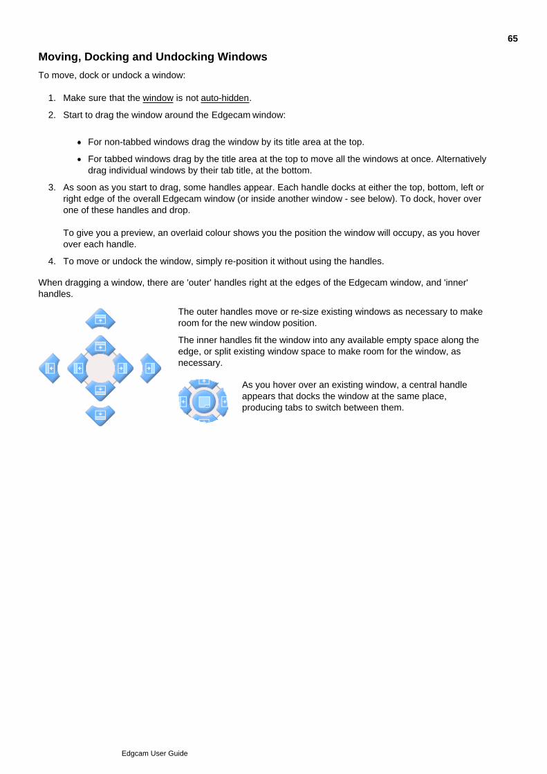
Moving, Docking and Undocking Windows
To move, dock or undock a window:
Make sure that the window is not auto-hidden.1.
Start to drag the window around the Edgecam window:
For non-tabbed windows drag the window by its title area at the top.
For tabbed windows drag by the title area at the top to move all the windows at once. Alternativelydrag individual windows by their tab title, at the bottom.
2.
As soon as you start to drag, some handles appear. Each handle docks at either the top, bottom, left orright edge of the overall Edgecam window (or inside another window - see below). To dock, hover overone of these handles and drop.
To give you a preview, an overlaid colour shows you the position the window will occupy, as you hoverover each handle.
3.
To move or undock the window, simply re-position it without using the handles.4.
When dragging a window, there are 'outer' handles right at the edges of the Edgecam window, and 'inner'handles.
The outer handles move or re-size existing windows as necessary to makeroom for the new window position.
The inner handles fit the window into any available empty space along theedge, or split existing window space to make room for the window, asnecessary.
As you hover over an existing window, a central handleappears that docks the window at the same place,producing tabs to switch between them.
65
Edgcam User Guide

Feedback in a Dialog
You can display information in a dialog, rather than the Feedback Window.
This would be useful if, for example, you were verifying several entities in one operation. In a dialog you wouldsee information on one entity, clicking the OK button moves on to the next entity.
To display information in a dialog:
Click the Preferences (Options menu) command to display the Preferences dialog.1.
Switch to the General tab and click Feedback Dialog to check it.2.
66
Edgcam User Guide

Adding and Removing Buttons
(Note that as an alternative to adding and removing buttons, you can show and hide buttons.)
To add or remove buttons, first:
Right-click on any toolbar.1.
In the subsequent shortcut menu click Customise to open the Customise dialog.2.
Then to remove a button:
If necessary, expand the menu containing the button.1.
Start to drag the button from its toolbar or menu. As soon as an 'x' symbol appears you can drop thebutton to remove it. (Note this does not involve the Customise dialog, which only needs to be open).
2.
Or to add a button (note that you need to do this if you find a command missing from the User Interface that ismentioned elsewhere in this Help system):
In the Customise dialog switch to the Commands tab.
Now use the tab to add a command button or a menu button. Here is the tab's help, for information:
67
Edgcam User Guide

Customising Buttons' Appearance
Right-click on any toolbar.1.
In the subsequent shortcut menu click Customise to open the Customise dialog.2.
Right-click on the button you want to change and in the subsequent shortcut menu click ButtonAppearance.
(Note this is not in the dialog, right-click on the actual button.)
3.
Use the Button Appearance dialog to make your required changes. You can:
Set whether the button appears as an image, text or both. (If the 'Image' option is not available, thetoolbar has 'Show text labels' enabled.)
Change the text of the button.
Change the image to one of the supplied alternative images, or to your own customised image.
Re-set to 'Use Default Image'.
4.
Note that you can't change the button's Description.
68
Edgcam User Guide

Changing a Button's Image
When changing a button's appearance, you can change the button's image.
After opening the Button Appearance dialog:
Click Select User-defined Image.
You can now optionally:
Open an editor for creating a new image by clicking New.
Edit an existing image in the editor by clicking the image and clicking Edit.
Once you have completed the editing, click the editor's OK button. The image then becomes oneof the images that you can use for the button.
1.
Click on the image you want to use and click OK.2.
Note that the changes only apply to a particular size of button. For example if you changed the image withMedium selected as the menu button size (see Changing The Button Size), you would not see the new imageon switching to the Large size. You need to repeat the changes in each button size.
69
Edgcam User Guide

Showing and Hiding Buttons
You can show or hide a button within its toolbar, as an alternative to adding or removing the button.
For the toolbar in which the button appears, click on the ' ' or ' ' symbol. This is in the title area ofundocked toolbars, or in the bar at the right-hand end of docked toolbars.
1.
Rest the cursor on Add or Remove Buttons, that appears.2.
In the list of toolbars that appears, rest the cursor on the toolbar containing the button. This list containsall the toolbars docked at the same edge of the Graphics Area as the toolbar you are working on (or justthe toolbar you are working on if it is undocked).
3.
In the list of buttons that appears, click on a checked button to uncheck and hide it, click on anunchecked button to check it and show it.
4.
70
Edgcam User Guide

Moving Buttons
You can move buttons from one toolbar or menu to another:
Right-click on any toolbar.1.
In the subsequent shortcut menu click Customise to open the Customise dialog.2.
Click on the menu containing the button to expand it.3.
From the menu drag the button; drag it over a toolbar or a menu and a bar indicates where the button willbe moved to (menus expand automatically).
4.
Drop the button when it is in the correct position.5.
71
Edgcam User Guide

Copying a Button's Image
You can copy the image of a button to the clipboard as a bitmap. You could then, for example, paste thebitmap into an image editor (including the in-built button image editor) as the basis for a new button image, thatyou can paste back into the image editor.
Right-click on any toolbar.1.
In the subsequent shortcut menu click Customise to open the Customise dialog.2.
Right-click on the button and in the subsequent shortcut menu click Copy Button Image.3.
72
Edgcam User Guide

Showing Button ScreenTips
You can choose whether or not the text (name) of a button is displayed as a screentip when you rest the cursoron it:
Right-click on any toolbar.1.
In the subsequent shortcut menu click Customise to open the Customise dialog.2.
Switch to the Options tab.3.
Now use the tab to show screentips. Here is the tab's help, for information:
73
Edgcam User Guide

Adding and Removing Menus
Menus are a type of button, so you add and remove them using the procedure detailed in Adding andRemoving Buttons.
When you do this you can add a button for a new menu (which also creates the menu), using the 'New Menu'item.
74
Edgcam User Guide

Changing the Button Size
You can change the size of buttons in the toolbars and in the menus. The changes are independent; you canchange one or the other or both.
Right-click on any toolbar.1.
In the subsequent shortcut menu click Customise to open the Customise dialog.2.
Switch to the Appearance tab.3.
You can now use the tab to change the button size. Here is the tab's help, for information:
75
Edgcam User Guide

Showing Shortcut Keys in ScreenTips
If you have opted to show screentips for buttons, you can opt for the shortcut key for the button's command tobe included in the screentip:
Right-click on any toolbar.1.
In the subsequent shortcut menu click Customise to open the Customise dialog.2.
Switch to the Options tab.3.
Now use the tab to show shortcut keys in screentips. Here is the tab's help, for information:
76
Edgcam User Guide

Using Menu Animations
You can change the way menus expand when you click on their button (the expanded menu can 'fade in' forexample):
Right-click on any toolbar.1.
In the subsequent shortcut menu click Customise to open the Customise dialog.2.
Switch to the Menus tab.3.
You can now use the tab to change the animation. Here is the tab's help, for information:
77
Edgcam User Guide

Using Menu Drop Shadows
You can opt for expanded menus to appear with a drop shadow around them:
Right-click on any toolbar.1.
In the subsequent shortcut menu click Customise to open the Customise dialog.2.
Switch to the Menu tab.3.
You can now use the tab to add drop shadows. Here is the tab's help, for information:
78
Edgcam User Guide

Showing and Hiding Toolbars
Right-click on any toolbar.1.
In the subsequent shortcut menu rest the cursor on Toolbars .2.
In the subsequent list of toolbars click on an un-checked toolbar to show it, click on a checked toolbar tohide it.
3.
Alternatively:
Right-click on any toolbar.1.
In the subsequent shortcut menu click Customise to open the Customise dialog.2.
Click on the Toolbars tab title.3.
You can now use the tab to show and hide toolbars. Here is the tab's help, for information:
79
Edgcam User Guide

Resetting Toolbars
(Note that resetting toolbars does not reset the menu bar; you need to follow the procedure in Resetting theMenu Bar.)
To reset toolbars:
Right-click on any toolbar.1.
In the subsequent shortcut menu click Customise to open the Customise dialog.2.
Switch to the Toolbars tab.3.
You can now use the tab to reset toolbars. Here is the tab's help, for information:
80
Edgcam User Guide

Moving, Docking and Undocking Toolbars
Start to drag the toolbar around the Graphics Screen, in the middle and towards the edges.
If the toolbar is undocked, drag it by its title area at the top.
If the toolbar is docked, use its dotted bar at the left hand side or top - .
1.
As you move through the various positions where you could drop the toolbar, an outline box shows youhow the toolbar would appear in that position (docked or undocked). When you are happy with thisposition, drop the toolbar.
2.
81
Edgcam User Guide

Changing the Shape of a Toolbar
You can change the shape of toolbars so that their buttons are arranged, for example, in a horizontal line or ina square block:
Rest the cursor over an edge of the toolbar; it changes to ' '.1.
Click and drag the edge of the toolbar. You can:
drag the left and right edges horizontally to change the width, with the height automaticallychanging.
drag the to and bottom edges vertically to change the height, with the width automaticallychanging.
Note that the shape only changes when you have moved the cursor beyond the new edge position; so forlarge toolbars, you may have to move the cursor quite a long way.
2.
When the cursor is in the required shape, drop the toolbar edge.3.
82
Edgcam User Guide

Resetting the Menu Bar
To reset the Menu bar:
Right-click on any toolbar.1.
In the subsequent shortcut menu click Customise to open the Customise dialog.2.
Click on the Menu tab title.3.
You can now use the tab to reset the Menu bar. Here is the tab's help, for information:
83
Edgcam User Guide

Showing Buttons as Text
You can ensure that all a toolbar's buttons appear with text (Note that this disables the 'Image' only appearancesetting that you can set for the individual buttons.)
Right-click on any toolbar.1.
In the subsequent shortcut menu click Customise to open the Customise dialog.2.
Switch to the Toolbars tab.3.
You can now use the tab to show buttons' text. Here is the tab's help, for information:
84
Edgcam User Guide

Changing the Appearance of Toolbars
You can change the style of toolbars, in terms of their colour and border for example:
Right-click on any toolbar.1.
In the subsequent shortcut menu click Customise to open the Customise dialog.2.
Switch to the Appearance tab.3.
You can now use the tab to show toolbars' style. Here is the tab's help, for information:
85
Edgcam User Guide

Creating Toolbars
You can create your own toolbars. As soon as you create the toolbar, it appears undocked within the GraphicsArea. You can then work with the toolbar as normal; you can dock it and add buttons to it, for example.
To create a toolbar:
Right-click on any toolbar.1.
In the subsequent shortcut menu click Customise to open the Customise dialog.2.
Click on the Toolbars tab title.3.
You can now use the tab to create toolbars. Here is the tab's help, for information:
86
Edgcam User Guide

Transferring Menu and Toolbar Configurations
You can save the configuration of an individual toolbar or menu to a file.
To do this:
Right-click on any toolbar.1.
In the subsequent shortcut menu click Customise.2.
In the Customise dialog that opens, click the Transfer tab title to switch to it.3.
You now work within the tab. Here is the tab's help, for information:
87
Edgcam User Guide

Assigning Shortcut keys
To assign shortcut keys to a command:
Right-click on any toolbar.1.
In the subsequent shortcut menu click Customise to open the Customise dialog.2.
Switch to the Keyboard tab.3.
Now use the tab to assign shortcut keys. Here is the tab's help, for information:
88
Edgcam User Guide

Creating Commands
To create a command:
Right-click on any toolbar.1.
In the subsequent shortcut menu click Customise to open the Customise dialog.2.
Switch to the Tools tab.3.
Now use the tab to create a command. Here is the tab's help, for information:
89
Edgcam User Guide

Resetting Shortcut Keys
You can reset shortcut keys assignments back to the 'factory' installation settings (to restore the assignmentsin the configuration, re-select the configuration):
Right-click on any toolbar.1.
In the subsequent shortcut menu click Customise to open the Customise dialog.2.
Switch to the Keyboard tab.3.
Click the Reset All button.4.
90
Edgcam User Guide

Setting Graphics Area Shortcut Menu options
To set the options for the Graphics Area Shortcut menu:
Click the Options menu and click Shortcut to open the Shortcut dialog.1.
Use the slider to set the Shortcut Delay (how long you have to hold the right mouse key down before themenu appears, whilst carrying out an action such as drawing a line).
2.
Click in the History box limit box and set a value. This is how many of the recently used shortcut menucommands are remembered and placed at the end of the shortcut menu.
3.
91
Edgcam User Guide

Using Undo and Redo
Use Edit menu Undo to step back from your last action in Edgecam.
For example:
If you drew a line, the line will be deleted,
If you changed a Depth value in a cycle, the value will revert back to the previous setting,along with the cycle's toolpath (the toolpath is retrieved from the Undo/Redo cache, so itdoes not need to be re-generated with the previous value).
You can make repeated Undos to step back through several actions.
You can then use Redo to step forwards again through your actions.
Once you make a new action however, you will not be able to make any more steps forward fromthere - only steps backward.
Note that you cannot use Undo while in Instructions Insert mode in Manufacture.
92
Edgcam User Guide
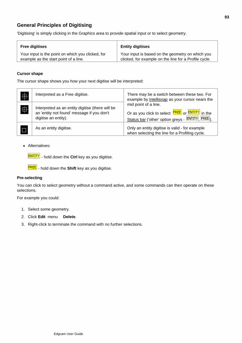
General Principles of Digitising
'Digitising' is simply clicking in the Graphics area to provide spatial input or to select geometry.
Free digitises
Your input is the point on which you clicked, forexample as the start point of a line.
Entity digitises
Your input is based on the geometry on which youclicked, for example on the line for a Profile cycle.
Cursor shape
The cursor shape shows you how your next digitise will be interpreted:
Interpreted as a Free digitise. There may be a switch between these two. Forexample by Intellisnap as your cursor nears themid point of a line.
Or as you click to select or in the
Status bar ('other' option greys - , ).
Interpreted as an entity digitise (there will bean 'entity not found' message if you don'tdigitise an entity).
As an entity digitise. Only an entity digitise is valid - for examplewhen selecting the line for a Profiling cycle.
Alternatives:
- hold down the Ctrl key as you digitise.
- hold down the Shift key as you digitise.
Pre-selecting
You can click to select geometry without a command active, and some commands can then operate on theseselections.
For example you could:
Select some geometry.1.
Click Edit menu Delete.2.
Right-click to terminate the command with no further selections.3.
93
Edgcam User Guide
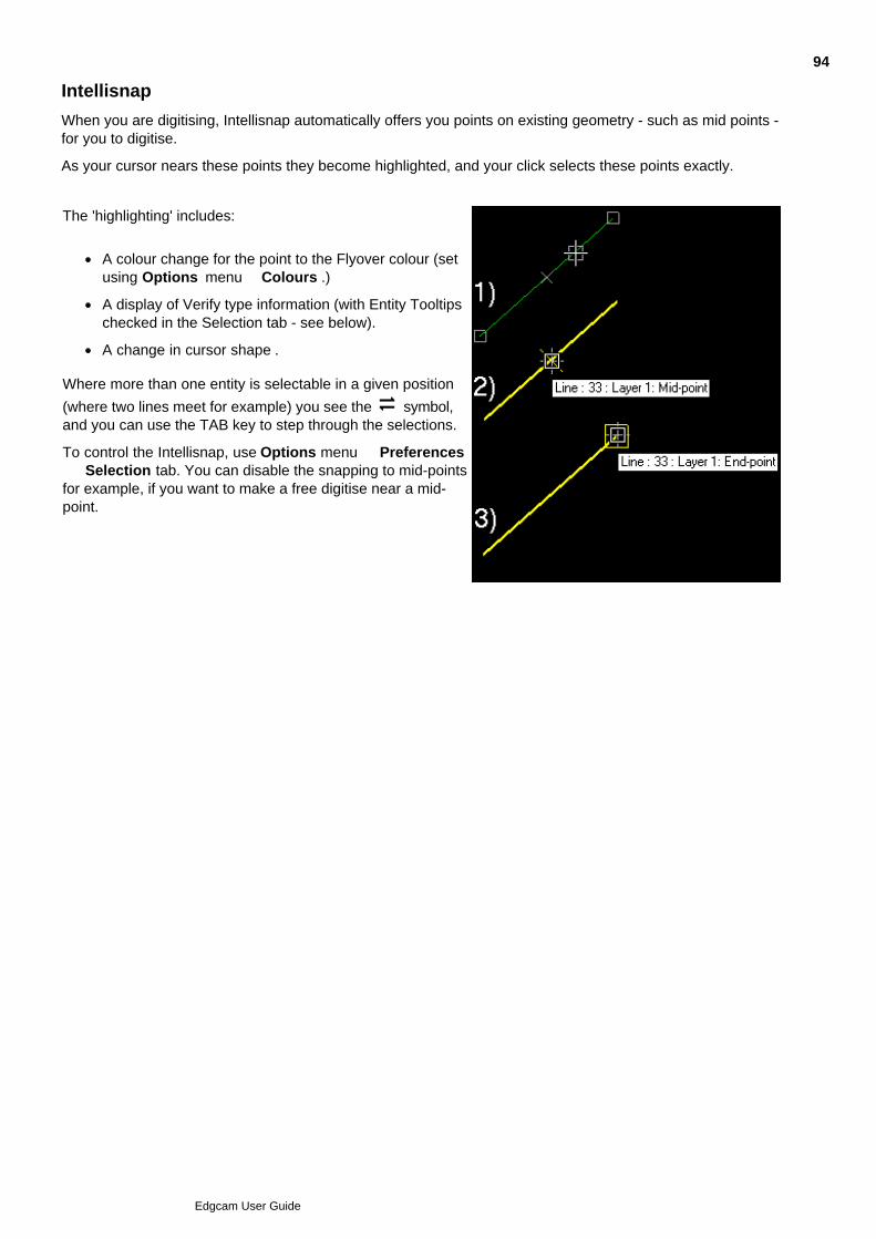
Intellisnap
When you are digitising, Intellisnap automatically offers you points on existing geometry - such as mid points -for you to digitise.
As your cursor nears these points they become highlighted, and your click selects these points exactly.
The 'highlighting' includes:
A colour change for the point to the Flyover colour (setusing Options menu Colours .)
A display of Verify type information (with Entity Tooltipschecked in the Selection tab - see below).
A change in cursor shape .
Where more than one entity is selectable in a given position
(where two lines meet for example) you see the symbol,and you can use the TAB key to step through the selections.
To control the Intellisnap, use Options menu Preferences Selection tab. You can disable the snapping to mid-pointsfor example, if you want to make a free digitise near a mid-point.
94
Edgcam User Guide
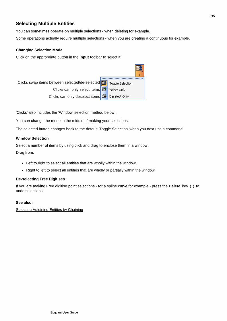
Selecting Multiple Entities
You can sometimes operate on multiple selections - when deleting for example.
Some operations actually require multiple selections - when you are creating a continuous for example.
Changing Selection Mode
Click on the appropriate button in the Input toolbar to select it:
Clicks swap items between selected/de-selected
Clicks can only select items
Clicks can only deselect items
'Clicks' also includes the 'Window' selection method below.
You can change the mode in the middle of making your selections.
The selected button changes back to the default 'Toggle Selection' when you next use a command. Window Selection
Select a number of items by using click and drag to enclose them in a window.
Drag from:
Left to right to select all entities that are wholly within the window.
Right to left to select all entities that are wholly or partially within the window.
De-selecting Free Digitises
If you are making Free digitise point selections - for a spline curve for example - press the Delete key ( ) toundo selections.
See also:
Selecting Adjoining Entities by Chaining
95
Edgcam User Guide
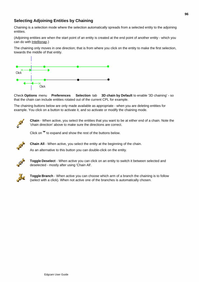
Selecting Adjoining Entities by Chaining
Chaining is a selection mode where the selection automatically spreads from a selected entity to the adjoiningentities.
(Adjoining entities are when the start point of an entity is created at the end point of another entity - which youcan do with Intellisnap.)
The chaining only moves in one direction; that is from where you click on the entity to make the first selection,towards the middle of that entity.
Check Options menu Preferences Selection tab 3D chain by Default to enable '3D chaining' - sothat the chain can include entities rotated out of the current CPL for example.
The chaining buttons below are only made available as appropriate - when you are deleting entities forexample. You click on a button to activate it, and so activate or modify the chaining mode.
Chain - When active, you select the entities that you want to be at either end of a chain. Note the'chain direction' above to make sure the directions are correct.
Click on to expand and show the rest of the buttons below.
Chain All - When active, you select the entity at the beginning of the chain.
As an alternative to this button you can double-click on the entity.
Toggle Deselect - When active you can click on an entity to switch it between selected anddeselected - mostly after using 'Chain All'.
Toggle Branch - When active you can choose which arm of a branch the chaining is to follow(select with a click). When not active one of the branches is automatically chosen.
96
Edgcam User Guide

Controlling Entity Selection
Click Entity Types in the Input toolbar if you want only certain types of entity to beselectable.
In the dialog that opens you check the entity types that you want to be selectable (Lines, Arcs, Points and soon).
The selections only last for the duration of the current command.
The dialog opens with the valid types for the command checked.
97
Edgcam User Guide

Snapping to Grid Points
Use View menu Grid to display a grid.
In the Status bar you can now choose whether to snap Free digitises to the grid or not:
GRID Free The grid intersection point nearest your click is selected.GRID Free The grid intersection point nearest your click is selected.
Click Click
GRID Free Where you click is selected.GRID Free Where you click is selected.
Note that with Free selected you can snap individual digitises by holding down the Shift and Ctrl keys as youNote that with Free selected you can snap individual digitises by holding down the Shift and Ctrl keys as youclick.
Use View menu Grid Configure to set the grid width, height, spacing and so on.
98
Edgcam User Guide

How to Start Edgecam
To run Edgecam
Make sure you are logged on as an Administrator or Power User.1.
Click Windows' Start menu All Programs Edgecam Edgecam .
(In a standard installation).
2.
99
Edgcam User Guide

Creating a New Part
When you open Edgecam, you can start a new drawing straight away.
If you have been working on a drawing and saved it, select New (File menu) to clearthe drawing area and begin a new drawing.
If the active part has not been saved since changes were made, then you are prompted to save or discardthose changes.
100
Edgcam User Guide

Saving Parts
The commands in the File menu that save an Edgecam drawing are:
Save – Use this command when you are saving a drawing for the first time, or if you want to save modificationsto a drawing under the same name.
Save As – Use this command only if you want to give the drawing a different name and keep the last savedversion under the old name.
Save Limited – This works in the same way as Save As but you can specify what you want to save from thecurrent part. You are prompted to digitise a new origin for the limited save and to digitise the entities that youwant to save.
Drawings are saved as .ppf (Pathtrace Part Files). See File Extensions Used in Edgecam for a list of othercommon file types. Both commands open the standard Windows dialog box for saving files. Saving a drawingalso saves the dimensions, units and so on with the drawing.
See Also
Autosave
Saving Notes for a Part
101
Edgcam User Guide

Autosave
Edgecam provides an automatic save capability.
Use the Preferences (Options menu) command to enter the number of commands after which an automaticsave will take place. The default is 5. To disable Autosave, set a value of zero.
Only commands that affect the model are counted – display commands are not taken into account. EachAutosave overwrites the previous save.
Autosave is part of your defaults – whether Autosave is on or off, and the number of commands betweenAutosaves is stored.
To load the Autosaved part, select the Open Autosave (File menu) command.
102
Edgcam User Guide
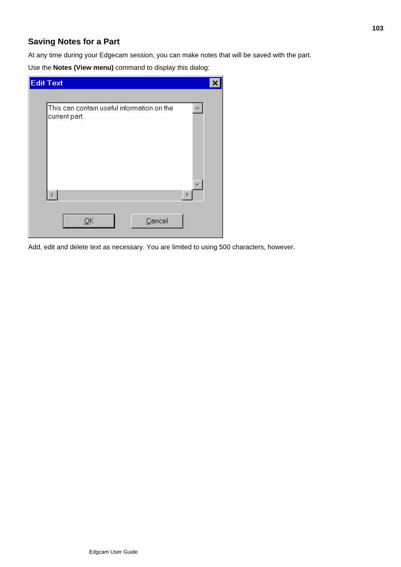
Saving Notes for a Part
At any time during your Edgecam session, you can make notes that will be saved with the part.
Use the Notes (View menu) command to display this dialog:
Add, edit and delete text as necessary. You are limited to using 500 characters, however.
103
Edgcam User Guide

Exporting Data
Parts can be saved in a number of formats for use in other CAD systems. The following file types aresupported:
.ppf (Edgecam default file type)
.dxf (AutoCAD)
.igs (IGES format ASCII file)
Select the correct file extension when using the Save (File menu) or Save As (File menu) commands.For more information about importing and exporting data, see CAD Interface File Formats.
104
Edgcam User Guide
File Extensions used in Edgecam
$$$ – Temporary files.
2XT CXT 4XT MXTWXT – Code Generator text files.
BMP – Bitmap produced by the Render command in Edgecam.
CLC – Compiled task file.
DBF – Database file used in Tool Library.
DFT – Default settings for Edgecam.
DOC – Document file produced when a Code Generator is compiled.
EXE – Executable file, for example a PDI file.
FNT – Text font definition files.
ICP – Compiled Code Generator file.
IXP – Code Generator text (source) file.
LAN – Compiled language files.
LC – Task file.
LOG – Manreadable report file.
MAC – Code Generator appended text file.
MCP – Compiled Code Generator file.
MDV – Machine communications definition file.
MDX – Cross reference file used in Tool Library.
MNU – Menu files for Code Generators & main system.
NC – Text file containing NC code.
PCI – Command Macro file produced by an Edgecam command save.
PLT – Plot control files.
PPF – Pathtrace Part File. Contains all design and manufacture information on an Edgecam part.
SYS – Edgecam model record file.
TCP – Compiled Code Generator file.
WCP – Compiled Code Generator file.
105
Edgcam User Guide

Opening Parts
To open a part:
In the File menu or Standard toolbar, click Open1.
Use the standard Open dialog to navigate to your part file and open it.
For Edgecam part files (.ppf), and certain other file types, you see a thumbnail preview of the selectedpart in the list. For large numbers of files this can cause a delay, so you can click Show Preview dodisable the preview. (These are the same thumbnails you see when viewing thumbnails in WindowsExplorer).
To limit the list to certain file types, click in the Files of type box and select the type from the list.
2.
Please Note:
The .ppf file type thumbnail is generated from the Edgecam view active when you save the part. Anywindows overlaying the part, such as the Simulator window, may cause the image to be captured fromthat window.
Pre-version 7.50 Edgecam parts must be re-saved for the thumbnail image to be created.
You can also insert a part into another drawing.
You can also open Autosaved parts.More information is available on opening solid model files.
106
Edgcam User Guide

Inserting Edgecam Parts
Use File menu Insert Part to open the dialog below.
(If you want to insert a sequence from another part, as well as the geometry use File menu Insert Component .)
107
Edgcam User Guide

Inserting a Part as a Component
The availability of this option is licence dependant.
Use File menu Insert Component to open the dialog below.
You can use File menu Insert Part if you only want to insert the geometry from another part(this command has more scaling and rotation options).
Also see Combining Components and Sequences.
108
Edgcam User Guide

Inserting a Symbol
The Insert, Symbol (File menu) command allows you to insert an Edgecam .ppf part as a symbol in thecurrent part. The symbol can only be manipulated as a single entity and may not be machined. An active link ismaintained between the current part and the part used as the symbol. If this symbol file is moved or deleted,the current part may be corrupted.
You may use the Explode (Edit menu) command to break up the symbol into individual entities. This breaksthe link with the symbol file and increases the size of the current part to accommodate the new entities.
Typical uses include drawing frames and company logos for drawings. These are standard objects that do notchange from part to part.
The parameters for this command are very similar to those in the Insert, Part (File menu) command.
109
Edgcam User Guide

Inserting Tool Graphics
The Insert, Tooling Graphics (File menu) command is available in Manufacture mode (and also in Designmode, licence permitting).
To load a tool graphics file, enter the Tooling Database by clicking on the Browse button. Select theappropriate database record to return to the Insert, Tool Graphics dialog. The Image field will be filled in. Clickon OK to insert the graphics file for the selected record.
110
Edgcam User Guide
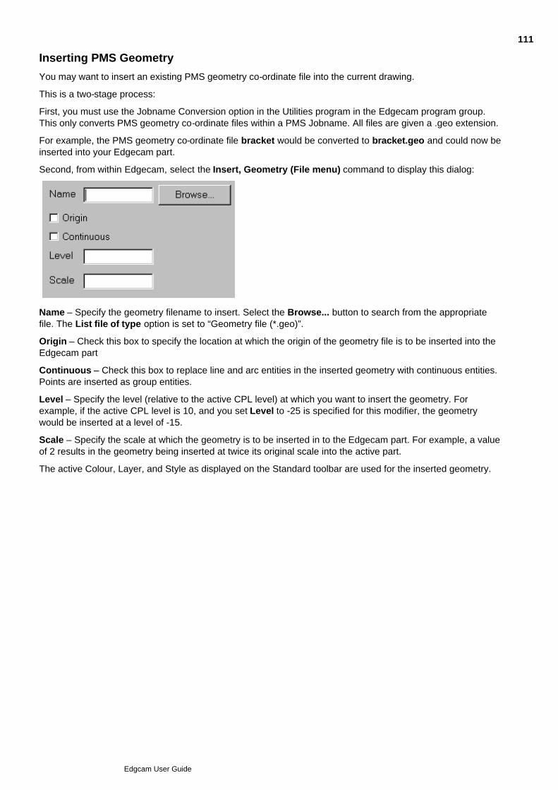
Inserting PMS Geometry
You may want to insert an existing PMS geometry co-ordinate file into the current drawing.
This is a two-stage process:
First, you must use the Jobname Conversion option in the Utilities program in the Edgecam program group.This only converts PMS geometry co-ordinate files within a PMS Jobname. All files are given a .geo extension.
For example, the PMS geometry co-ordinate file bracket would be converted to bracket.geo and could now beinserted into your Edgecam part.
Second, from within Edgecam, select the Insert, Geometry (File menu) command to display this dialog:
Name – Specify the geometry filename to insert. Select the Browse... button to search from the appropriatefile. The List file of type option is set to “Geometry file (*.geo)”.
Origin – Check this box to specify the location at which the origin of the geometry file is to be inserted into theEdgecam part
Continuous – Check this box to replace line and arc entities in the inserted geometry with continuous entities.Points are inserted as group entities.
Level – Specify the level (relative to the active CPL level) at which you want to insert the geometry. Forexample, if the active CPL level is 10, and you set Level to -25 is specified for this modifier, the geometrywould be inserted at a level of -15.
Scale – Specify the scale at which the geometry is to be inserted in to the Edgecam part. For example, a valueof 2 results in the geometry being inserted at twice its original scale into the active part.
The active Colour, Layer, and Style as displayed on the Standard toolbar are used for the inserted geometry.
111
Edgcam User Guide

Creating Job Images
Edgecam provides the easy creation of job report images which are captured when using the job in Edgecamand placed in the HTML pages of the Job reports.
If you have specified a job for the machining sequence, select the Job Images (File menu) command to savethe desired screen image(s) together with the job.
Please note that this requires at least 24-bit colour. If you experience problems please check the Displaysettings of your PC. Depending on your graphics card, the valid options may include 24-bit, 32-bit, 16 millioncolours or True Colour.
The Reports Images command in the Job Manager allows you to control the display of these images.
112
Edgcam User Guide

Printing
Select the Print (File menu) command to display a standard Windows Print dialog box. See Also
Setting up the Printer Setup
113
Edgcam User Guide
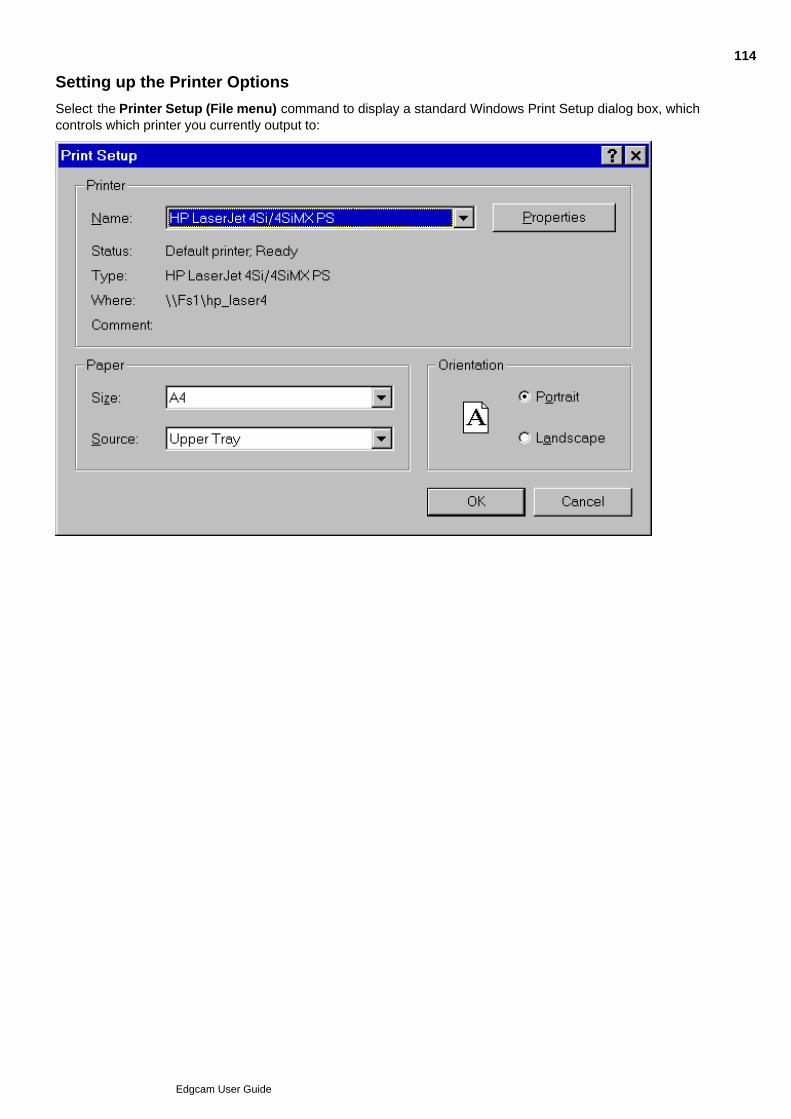
Setting up the Printer Options
Select the Printer Setup (File menu) command to display a standard Windows Print Setup dialog box, whichcontrols which printer you currently output to:
114
Edgcam User Guide

Plotting
Classic Edgecam View only
Note that, for the drawing to be plotted in 1:1 scale on the paper, you must prepare the part by:
Using the Drawing, Configure (View menu) command to set the paper X Size and Y Size, and1.
Using the Port, Configure (View menu) command to set the Scale of the appropriate port(s) to 1.2.
To plot a drawing
Select the Plot (File menu) command. The dialog box for the command is displayed.1.
Set the parameters for the command.2.
On the Options tab you can specify the following options.3.
Click OK to dismiss the dialog box.4.
The plot frame appears, and you can now move the plot frame around the drawing using the mouse.
Digitise to select the plot frame position.5.
The command now saves the contents of the plot frame to the named plot file.
115
Edgcam User Guide

Working with Part Properties
Edgecam parts (.ppf part files) have some:
Properties that you cannot edit - the 'SavedInVersion' property for example.
Properties you can edit to store useful information - the 'Keywords' and 'Comments' properties forexample.
To access the properties:
Click the File menu and click Properties.1.
Work with the properties in the Properties Window.2.
Note that these properties:
Are available for access in data management systems such as Autodesk Vault, when you archive thepart file in the system.
Are accessible via Windows Explorer; right-click on the part file and select Properties.
116
Edgcam User Guide
Selecting the Environment
Edgecam operates within an environment which is selectable according to the type of part being designed ormanufactured. Selection of an environment determines which construction planes, view port layouts andcommands are available. (These terms are explained later in this section.)
An environment provides you with orientations and views of the component that match particular tool types.You can design a component in either environment and change environments at will. This has no effect on thecomponent other than to change the views of the component that the system presents to you.
There are two environments to choose from:
XY Environment
This provides view ports and construction planes for constructing a part with respect to the usual X, Y, ZCartesian co-ordinate system. This is the default environment when entering Edgecam. Typically, the XYenvironment is used for generating Milling, Wire and CMM components.
ZX Environment
This environment provides view ports and construction planes that simulate the orientation of a turned part in amachine tool during manufacture. In the case of a lathe for example, it is usual to work in the ZX plane wherethe Z axis is horizontal.
If a turned component is drawn in the XY plane, you can flip the component into the ZX plane using theTransform, Transpose (Edit menu) command.
You can switch between environments when designing a part by selecting one of the XY Environment or ZXEnvironment commands from the Options menu. These environments are mutually exclusive and the activecommand is shown with a ‘tick’ againt it.
You can also select an XY or ZX Environment from within the Preferences (Options menu) command.
117
Edgcam User Guide
Regenerating (toolpaths)
Toolpaths may need to be regenerated to bring them up to date with edits you make to instructions, such as achanged tool diameter.
This should be done before generating CNC code.
You can manually regenerate at any time, as detailed below.
You can also enable Automatic Regeneration, so that regeneration is automatically triggered - on editing aninstruction for example. This is also detailed below.
Automatic Regeneration
This is enabled by default and is recommended as it reduces the risk of producing incorrect CNC code.
Only disable automatic regeneration if it produces too much of a delay.
An Instruction is (nearly) always regenerated when you edit the instruction. With Auto-Regenerate enabled, allthe subsequent instructions in the sequence are also updated. (This is because some instructions aredependant on others, a Rest-Rough cycle is dependent on a Roughing cycle, for example.)
You can also opt for automatic regeneration on reloading the open solid model.
You can edit an instruction without it being regenerated by using Instructions menu Edit. In the EditingInstructions dialog that opens you and check Disable Automatic Regeneration before moving on to edit theinstruction).
Manual Regeneration
You can manually regenerate:
Using the Regenerate options in the shortcut menu for the Sequence Window.
Using the Regenerate command. This method gives you more control over the regeneration.
See also
Using Batch Mode for Operations
118
Edgcam User Guide

Co-ordinate Types
You can specify co-ordinates in a variety of types:
Cartesian
Polar
Angular
You can select the type of co-ordinates to be used in the Co-ordinate Input dialog box which is activated by the
button (see Specifying Explicit Co-ordinates).
119
Edgcam User Guide

About Cartesian Co-ordinates
This is the usual system of rectangular X, Y, Z axes and co-ordinates. The point where the three axes meet iscalled the Origin and has co-ordinates X=0, Y=0, Z=0.
The example shows a point at co-ordinates X=x, Y=y, Z=z:
By convention, if the X, Y axes lie in the plane of the screen, the Z axis points up out of the screen.
120
Edgcam User Guide
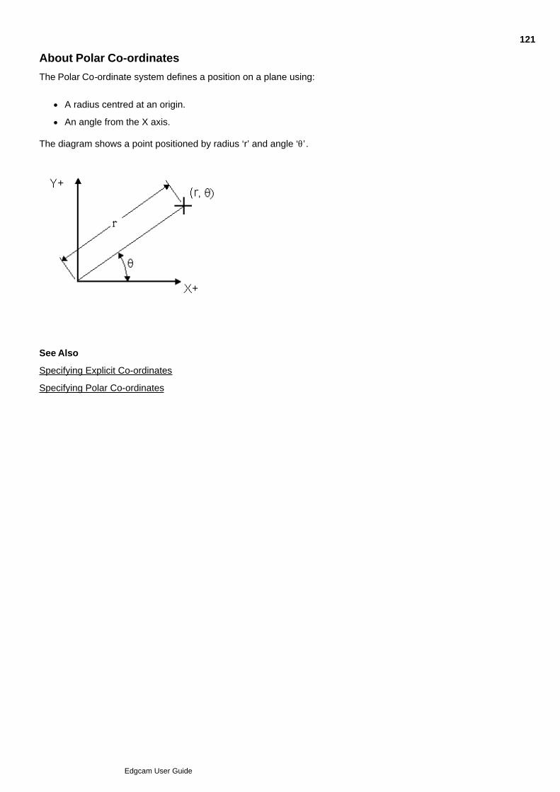
About Polar Co-ordinates
The Polar Co-ordinate system defines a position on a plane using:
A radius centred at an origin.
An angle from the X axis.
The diagram shows a point positioned by radius ‘r’ and angle ‘q’ .
See Also
Specifying Explicit Co-ordinates
Specifying Polar Co-ordinates
121
Edgcam User Guide
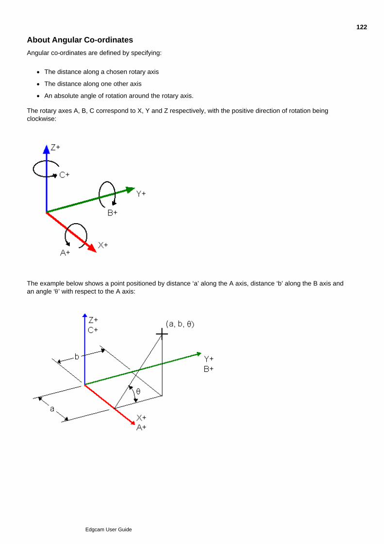
About Angular Co-ordinates
Angular co-ordinates are defined by specifying:
The distance along a chosen rotary axis
The distance along one other axis
An absolute angle of rotation around the rotary axis.
The rotary axes A, B, C correspond to X, Y and Z respectively, with the positive direction of rotation beingclockwise:
The example below shows a point positioned by distance ‘a’ along the A axis, distance ‘b’ along the B axis andan angle ‘q’ with respect to the A axis:
122
Edgcam User Guide

Entity Types
In Edgecam terms, a part is the sum of all the entities which produce that part.
Edgecam provides several entity types that you can use when designing and manufacturing components:
Point Entities
Line Entities
Circle and Arc Entities
Curve Entities
Surface Entities
Continuous Entities
Group Entities
Detailing Entities
Toolpath Entities
123
Edgcam User Guide

Point Entities
A point is the simplest geometric entity.
A point is defined in 3D space. Whichever co-ordinate system is used to set up the point, it is always stored asthree real numbers in Cartesian co-ordinates.
Methods of point definition include:
Absolute co-ordinate position
Arc centre
Screen position
Existing point
Middle point of an existing entity known as a mid-point
End point of an existing entity
Intersection of any two entities
A distance modification from any of the above point definitions
See Also
Creating Points
124
Edgcam User Guide

Line Entities
A line has two end points and can be constructed by any of these methods:
Between two point definitions
Between a point and an arc tangency point
Between two arc tangency points
Through a point and parallel to another line
Through a point and perpendicular to another line
See Also
Creating Lines
125
Edgcam User Guide

Circle and Arc Entities
A circle is a non-linear geometric entity, every point of which is equally distant from a fixed central point.
An arc is a segment of a circle. Arc construction is similar to circle construction, except that the end points ofthe arc also must be defined.
Methods of circle definition include:
A point definition as the centre and specifying a radius
A point definition as the centre and a point on the circle
Three points which the circle passes through
A circle tangent to three lines
Tangency to two entities and specifying the radius
126
Edgcam User Guide

Curve Entities
A curve is a non-linear entity, described by an exact mathematical definition. Curves include Splines, B-Splines,Bezier curves and Conic sections.
127
Edgcam User Guide

Surface Entities
A surface is defined in Edgecam using a two-axis parametric co-ordinate system, and can be created fromcontrol points, entities or other surfaces.
Also see About Surfaces in Edgecam.
128
Edgcam User Guide

Continuous Entities
These are a set of colinear line or arc entities grouped together (for example, from a profile) for ease ofmanipulation.
See Converting to a Continuous Entity for a full explanation.
129
Edgcam User Guide

Group Entities
These are a set of Edgecam entities (for example, lines and arcs) that have been collected into a group forease of manipulation.
See Creating Group Entities for a full explanation.
130
Edgcam User Guide

Detailing Entities
These are entities created using Edgecam Detailing commands. As they are purely for dimensioning andannotating purposes, they do not form part of the 3D part model and exist only on the 'Drawing Plane'.
131
Edgcam User Guide

Toolpath Entities
A toolpath is created from within one of the Edgecam machining modules, and represents the track of anominated part of a machine tool. Each toolpath may be made up of many toolpath entities, which may beeither line or arc segments.
132
Edgcam User Guide

Entity Dependency
It is important to understand that one entity can be dependent on another. Certain operations cause entities tobe ‘flagged’ as having dependants (other entities dependent on them for their existence). Entities with one ormore dependants cannot be deleted or modified in a way that would invalidate the dependent entity.
Entity dependency occurs with surfaces, continuous entities and groups. For example, a Coons Patch surfaceis created from four other boundary lines. These lines cannot be deleted or altered without first deleting theCoons patch. It is possible to alter their colour, layer, style or name, as this would not invalidate the dependentsurface.
Edgecam entities which are dependent on other entities are:
· Coons Patches
· Tabulated cylinders
· Flowed surfaces
· Ruled surfaces
· Fillet surfaces
· Surfaces of revolution
· Surface curves
· Offset surfaces
· Crosshatching
· Groups
· Continuous entities
· Trimmed surfaces.
To find out whether an entity has a dependant, use the Entity (Verify menu) command. Amongst other details,the system reports one of the following: Dependency SET or Dependency CLEAR.
It is possible that the dependency flag for some entities is not cleared when the dependants are deleted. Whenyou reload the part, these entities cannot therefore be altered or deleted. To overcome this situation, insert thepart into Edgecam using the File menu command Insert Part. Only entities that still have dependants will havethe dependency flag set.
133
Edgcam User Guide

Entity Attributes
Each entity can have a colour, style, name and layer attribute. These attributes are reported if you verify theentity using the Entity (Verify menu) command.
See Also
ColourStyleNameCurve and Surface Attributes
134
Edgcam User Guide

Entity Colour
Use Colours in the Standard toolbar to set the colour for new entities (lines, arcs and so on).
Colours can be used to highlight different entity types, parts of the drawing or functionaldifferences.
You can change the colour of existing entities; you can use for example:
Edit menu > Entity Data Match (copies the colour, style and so on from one entity toanother).
Edit menu > Entity Data Individual (opens the properties dialog for the entity youthen select).
By opening the properties dialog directly from the entity.
135
Edgcam User Guide

Entity Style
Use Style in the Standard toolbar to set the style for new entities (lines, arcs and so on).
You can change the style of existing entities; you can use for example:
Edit menu > Entity Data Match (copies the colour, style and so on from one entity to another).
Edit menu > Entity Data Individual (opens the properties dialog for the entity you then select).
By opening the properties dialog directly from the entity.
Note that if a very fine display tolerance is used, the font for entities such as arcs and curves may not appear tobe correct. Use the Preferences (Options menu) command to increase the Display Tolerance.
136
Edgcam User Guide

Name
When you create an entity you can give it a name up to eight characters long. This name is saved for futurereference (for example, when selecting entities for a machining cycle). However, if the entity is copied, only theoriginal entity retains the name.
137
Edgcam User Guide
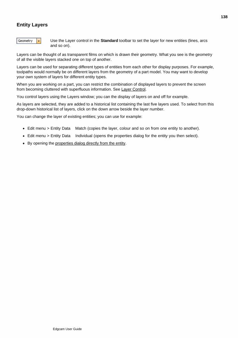
Entity Layers
Use the Layer control in the Standard toolbar to set the layer for new entities (lines, arcsand so on).
Layers can be thought of as transparent films on which is drawn their geometry. What you see is the geometryof all the visible layers stacked one on top of another.
Layers can be used for separating different types of entities from each other for display purposes. For example,toolpaths would normally be on different layers from the geometry of a part model. You may want to developyour own system of layers for different entity types.
When you are working on a part, you can restrict the combination of displayed layers to prevent the screenfrom becoming cluttered with superfluous information. See Layer Control.
You control layers using the Layers window; you can the display of layers on and off for example.
As layers are selected, they are added to a historical list containing the last five layers used. To select from thisdrop-down historical list of layers, click on the down arrow beside the layer number.
You can change the layer of existing entities; you can use for example:
Edit menu > Entity Data Match (copies the layer, colour and so on from one entity to another).
Edit menu > Entity Data Individual (opens the properties dialog for the entity you then select).
By opening the properties dialog directly from the entity.
138
Edgcam User Guide

Curve and Surface Properties
These entities are based on mathematically correct descriptions, but you can control the accuracy of theirscreen appearance. For example, a complex surface may take some time to draw, so you may want totemporarily degrade the appearance of the surface in exchange for a faster redraw time.
For more information, see About Curves and About Surfaces.
139
Edgcam User Guide

Selecting and Deleting Entities
To select all valid entities
If you want to select all entities, simply hold down the Ctrl key and press the 'A' key. This will select all valid,visible entities in the current view.
To delete entities
This functionality is only available in Design mode.
Instead of using the Delete Entity command, you can delete all visible entities in the current view by simply pre-selecting them and then pressing the Delete key.
If no entities have been selected when you press the Delete key, the Delete Entity command will be enabledand you will be prompted to “Digitise entities to delete”.
140
Edgcam User Guide
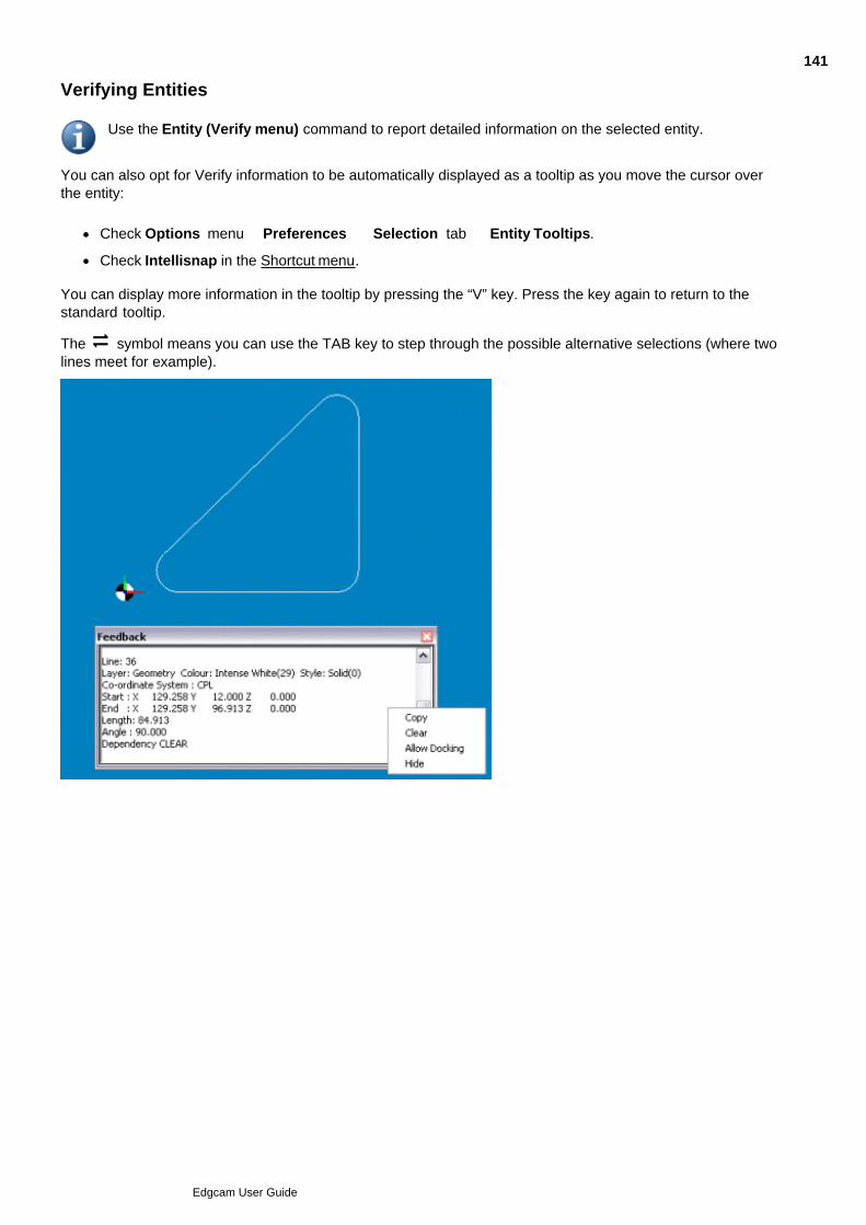
Verifying Entities
Use the Entity (Verify menu) command to report detailed information on the selected entity.
You can also opt for Verify information to be automatically displayed as a tooltip as you move the cursor overthe entity:
Check Options menu Preferences Selection tab Entity Tooltips.
Check Intellisnap in the Shortcut menu.
You can display more information in the tooltip by pressing the “V” key. Press the key again to return to thestandard tooltip.
The symbol means you can use the TAB key to step through the possible alternative selections (where twolines meet for example).
141
Edgcam User Guide
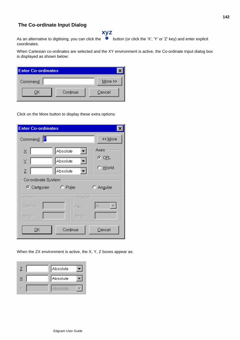
The Co-ordinate Input Dialog
As an alternative to digitising, you can click the button (or click the 'X', 'Y' or 'Z' key) and enter explicitcoordinates.
When Cartesian co-ordinates are selected and the XY environment is active, the Co-ordinate Input dialog boxis displayed as shown below:
Click on the More button to display these extra options:
When the ZX environment is active, the X, Y, Z boxes appear as:
142
Edgcam User Guide

Use the Co-ordinate System option buttons to select one of the three co-ordinate systems:
Cartesian co-ordinates
Polar co-ordinates
Angular co-ordinates
Use the Axes options to select whether co-ordinates are specified with respect to CPL or World axes. Theselection is registered in the Command box as a P for CPL axes or a W for World axes. If P is entered on itsown then a default position of X0Y0Z0 will be used.
143
Edgcam User Guide
Entering Cartesian Co-ordinates
To specify Cartesian co-ordinates
Type your required co-ordinates into the X, Y, Z boxes.1.
Ordinate values can be mathematical expressions using the + - * / operators. Brackets can be used toestablish the order of evaluation. If an ordinate value is not given, the previous value used in thecurrent command is used. If no previous value has been given, 0.0 is assumed.
If the 2D Snap option has been selected, Z ordinate values are ignored and the level of the currentlyselected CPL is used.
If a 2D CPL is current, Z ordinates cannot be entered.
Ordinate values are shown in the Command box as they are entered.
Choose how each ordinate is specified from these options.2.
Absolute – Ordinates are specified with respect to the selected axis system.
Incremental – Incremental ordinates are given with respect to the previous co-ordinate position. If noprevious position has been given, the increment is taken from the origin of the selected axis system.
When an Incremental option button is selected, the labelling of the associated X, Y or Z box appearsas IX, IY, IZ respectively and IX, IY or IZ appears in the command box.
Screen Select – Ordinates are specified by normal digitising methods. When this option is used, an X,Y or Z is shown in the command box.
Any mixture of these methods can be used to specify a set of co-ordinates.
When the Co-ordinate Input dialog box is closed, a prompt for the required ordinate is given in theStatus bar.
Select the OK or Continue buttons when you have completed your co-ordinate specification.3.
Specifying Cartesian Co-ordinates in Command Format
Experienced users can enter co-ordinates directly though the Command box. You can also display this box bypressing one of the keys that corresponds to an axis or a command (for example, X, Y, Z, A, B, C, I, W, R, P).
Absolute co-ordinates are specified in the form:
XnnYnnZnn
where nn is an ordinate value.
Each ordinate is optional and its name and value can be omitted. If an ordinate value is not given, the previousvalue used in the current command is used. If no previous value has been given, then 0.0 is assumed.
Incremental co-ordinates are specified in the form:
IXnnIYnnIZnn
where nn is an incremental ordinate value.
Each incremental ordinate is optional and its name and value can be omitted. Incremental ordinates are givenwith respect to the previous co-ordinate position. If no previous position has been given, the increment is takenfrom the origin of the selected axis system.
144
Edgcam User Guide

Specify screen selections by giving only X, Y or Z as required.
The methods used for specifying ordinate values can be mixed.
145
Edgcam User Guide
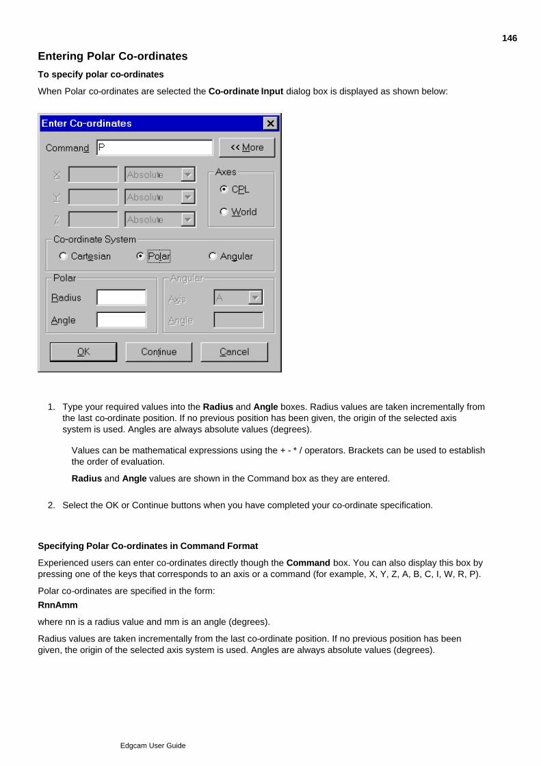
Entering Polar Co-ordinates
To specify polar co-ordinates
When Polar co-ordinates are selected the Co-ordinate Input dialog box is displayed as shown below:
Type your required values into the Radius and Angle boxes. Radius values are taken incrementally fromthe last co-ordinate position. If no previous position has been given, the origin of the selected axissystem is used. Angles are always absolute values (degrees).
1.
Values can be mathematical expressions using the + - * / operators. Brackets can be used to establishthe order of evaluation.
Radius and Angle values are shown in the Command box as they are entered.
Select the OK or Continue buttons when you have completed your co-ordinate specification.2.
Specifying Polar Co-ordinates in Command Format
Experienced users can enter co-ordinates directly though the Command box. You can also display this box bypressing one of the keys that corresponds to an axis or a command (for example, X, Y, Z, A, B, C, I, W, R, P).
Polar co-ordinates are specified in the form:
RnnAmm
where nn is a radius value and mm is an angle (degrees).
Radius values are taken incrementally from the last co-ordinate position. If no previous position has beengiven, the origin of the selected axis system is used. Angles are always absolute values (degrees).
146
Edgcam User Guide
Entering Angular Co-ordinates
To specify angular co-ordinates
Angular co-ordinates are defined by specifying:
The distance along a chosen rotary axis
The distance along one other axis
An absolute angle of rotation around the rotary axis.
Enter co-ordinate data as follows:
Select the Rotary Axis.1.
Type your required distances along the A, B and C axes into the X, Y and Z boxes respectively. This isdone in the way described for Cartesian co-ordinates.
2.
Enter the absolute angle (degrees) into the Angle box.3.
Select the OK or Continue buttons when you have completed your co-ordinate specification.4.
Specifying Angular Co-ordinates in Command Format
Experienced users can enter co-ordinates directly though the Command box. You can also display this box bypressing one of the keys that corresponds to an axis or a command (for example, X, Y, Z, A, B, C, I, W, R, P).
Angular co-ordinates are specified by entering a distance along a rotational axis, a distance along one otheraxis and then an angle of rotation, for example
X50Y50A90 should give a point at X50 Y0 Z50 because the point defined at X50Y50 is rotated by 90 degreesabout the X (A) axis.
147
Edgcam User Guide

2D Snap
The 2D snap command determines how co-ordinate information is obtained for acommand.
Activate the command to set all Z ordinates to the level of the current CPL, regardless of input method.
De-activate the command for full 3D operation with:
Entity digitises
Co-ordinates obtained by reference or by construction
Explicit co-ordinate input.
With free digitises, Z ordinates are always taken to be at the level of the current CPL.
Note: If either the CPL (Edit menu) or Create CPL (Geometry menu) command have been used to set thecurrent CPL to 2D, this command is not available.
148
Edgcam User Guide
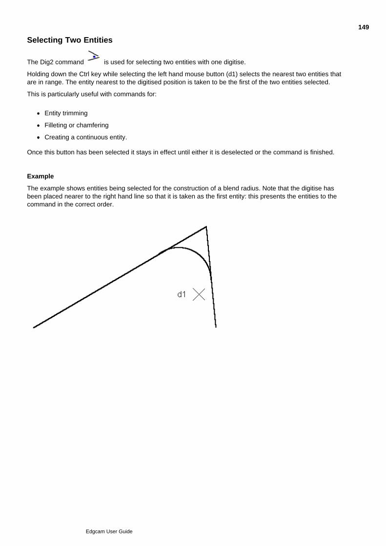
Selecting Two Entities
The Dig2 command is used for selecting two entities with one digitise.
Holding down the Ctrl key while selecting the left hand mouse button (d1) selects the nearest two entities thatare in range. The entity nearest to the digitised position is taken to be the first of the two entities selected.
This is particularly useful with commands for:
Entity trimming
Filleting or chamfering
Creating a continuous entity.
Once this button has been selected it stays in effect until either it is deselected or the command is finished.
Example
The example shows entities being selected for the construction of a blend radius. Note that the digitise hasbeen placed nearer to the right hand line so that it is taken as the first entity: this presents the entities to thecommand in the correct order.
149
Edgcam User Guide
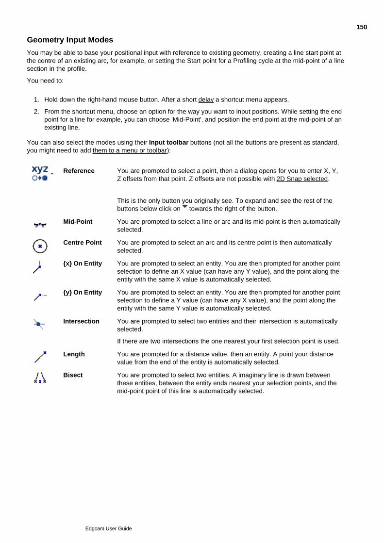
Geometry Input Modes
You may be able to base your positional input with reference to existing geometry, creating a line start point atthe centre of an existing arc, for example, or setting the Start point for a Profiling cycle at the mid-point of a linesection in the profile.
You need to:
Hold down the right-hand mouse button. After a short delay a shortcut menu appears.1.
From the shortcut menu, choose an option for the way you want to input positions. While setting the endpoint for a line for example, you can choose 'Mid-Point', and position the end point at the mid-point of anexisting line.
2.
You can also select the modes using their Input toolbar buttons (not all the buttons are present as standard,you might need to add them to a menu or toolbar):
Reference You are prompted to select a point, then a dialog opens for you to enter X, Y,Z offsets from that point. Z offsets are not possible with 2D Snap selected.
This is the only button you originally see. To expand and see the rest of thebuttons below click on towards the right of the button.
Mid-Point You are prompted to select a line or arc and its mid-point is then automaticallyselected.
Centre Point You are prompted to select an arc and its centre point is then automaticallyselected.
{x} On Entity You are prompted to select an entity. You are then prompted for another pointselection to define an X value (can have any Y value), and the point along theentity with the same X value is automatically selected.
{y} On Entity
You are prompted to select an entity. You are then prompted for another pointselection to define a Y value (can have any X value), and the point along theentity with the same Y value is automatically selected.
Intersection You are prompted to select two entities and their intersection is automaticallyselected.
If there are two intersections the one nearest your first selection point is used.
Length You are prompted for a distance value, then an entity. A point your distancevalue from the end of the entity is automatically selected.
Bisect You are prompted to select two entities. A imaginary line is drawn betweenthese entities, between the entity ends nearest your selection points, and themid-point point of this line is automatically selected.
150
Edgcam User Guide
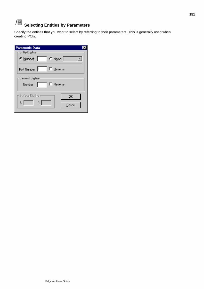
Selecting Entities by Parameters
Specify the entities that you want to select by referring to their parameters. This is generally used whencreating PCIs.
151
Edgcam User Guide
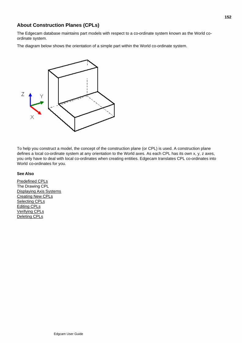
About Construction Planes (CPLs)
The Edgecam database maintains part models with respect to a co-ordinate system known as the World co-ordinate system.
The diagram below shows the orientation of a simple part within the World co-ordinate system.
To help you construct a model, the concept of the construction plane (or CPL) is used. A construction planedefines a local co-ordinate system at any orientation to the World axes. As each CPL has its own x, y, z axes,you only have to deal with local co-ordinates when creating entities. Edgecam translates CPL co-ordinates intoWorld co-ordinates for you. See Also
Predefined CPLsThe Drawing CPLDisplaying Axis SystemsCreating New CPLsSelecting CPLsEditing CPLsVerifying CPLsDeleting CPLs
152
Edgcam User Guide

Predefined CPLs
A set of predefined CPLs are provided for the XY and ZX environments.
This diagram shows the relationship between the CPL axes for the XY environment and the World axes. Thename of each CPL is shown.
The next diagram shows the relationship of the standard CPLs to each view of the part. Note that:
The origin of each standard CPL coincides with the World origin
The ‘top’ CPL is the only one where the CPL axes coincide exactly with the World axes.
If you need to add a feature, such as a slot, into the bottom of the part you can select the ‘bottom’ CPL andwork in terms of the dimensions you have without worrying about how they map back to the World axes.
Command modifier values for co-ordinates or angles of rotation are always given with respect to the currentCPL.
Explicit co-ordinate data can be given with respect to either the current CPL or the World co-ordinate system.See ‘Specify explicit co-ordinates’ in the section ‘Entering co-ordinate data and selecting entities’.
The following diagram shows the standard CPLs for the ZX environment using a ‘swept’ profile.
153
Edgcam User Guide

The Drawing CPL
Classic Edgecam View Only
The Drawing CPL is different from all the other CPLs as it is purely two dimensional. It is like a conventionaldrawing sheet on which views are assembled to provide the views which comprise an engineering drawing. Itsprimary purpose is to contain elements of a drawing that are not part of the 3D model, such as the dimensions,text and drawing symbols. By making the Drawing CPL current, it can also be used for making two dimensionaldrawings.
154
Edgcam User Guide

Displaying Axis Systems
The display of World and CPL axes can be controlled by Drawing, Configure (View menu) command. Worldaxes are displayed in white and CPL X, Y, Z axes are displayed in red, green and blue respectively.
155
Edgcam User Guide
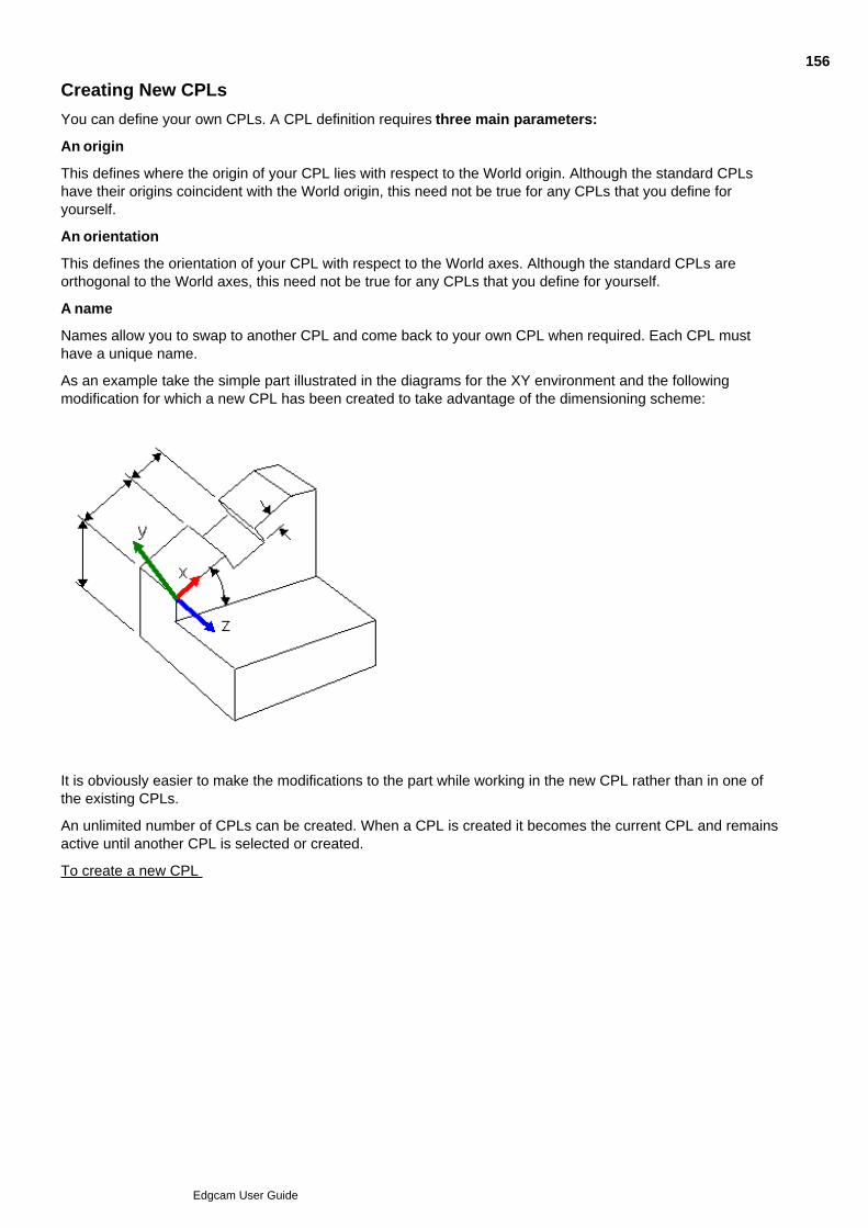
Creating New CPLs
You can define your own CPLs. A CPL definition requires three main parameters:
An origin
This defines where the origin of your CPL lies with respect to the World origin. Although the standard CPLshave their origins coincident with the World origin, this need not be true for any CPLs that you define foryourself.
An orientation
This defines the orientation of your CPL with respect to the World axes. Although the standard CPLs areorthogonal to the World axes, this need not be true for any CPLs that you define for yourself.
A name
Names allow you to swap to another CPL and come back to your own CPL when required. Each CPL musthave a unique name.
As an example take the simple part illustrated in the diagrams for the XY environment and the followingmodification for which a new CPL has been created to take advantage of the dimensioning scheme:
It is obviously easier to make the modifications to the part while working in the new CPL rather than in one ofthe existing CPLs.
An unlimited number of CPLs can be created. When a CPL is created it becomes the current CPL and remainsactive until another CPL is selected or created.
To create a new CPL
156
Edgcam User Guide

Selecting CPLs
To select a CPL (Construction Plane)
Select the Select CPL (Geometry menu) command.1.
By default, the Name box contains the name of the current CPL. The list of Names contains thestandard CPLs. As user defined CPLs are added to the part, the list is updated.
When changing from one CPL to another, the active Level is reset to zero. Enter a new level for theCPL, if required, by entering a value or digitising an entity from which to take the level information.
2.
This is the new distance from the CPL’s original plane of definition at which entities are created.
This can be used to change the level of the current CPL if nothing is selected from the Name list box.(The current level can also be changed from the Toolbar – or only the display of levels.)
If the ZX environment is current, set the Input Mode. The input mode determines whether X axisdimensions refer to Radial or Diametral values. If the mode is set to Diametral and the explicit co-ordinates X20Z20 are given, Edgecam takes the X value to be a diameter.
2.
Select the name of the CPL to be made current from the Name list box.3.
Click on OK.4.
157
Edgcam User Guide

Editing CPLs
For standard CPLs (Top, Front and so on) only the Work Plane parameter of a standard CPL can be edited.
You see a warning if you edit a CPL that is the 'Initial CPL' of a machining sequence, as there are potentialdangers. For example:
Rapids will move along with the CPL, as they are based on coordinate input or free digitises. Toolpathmoves associative to geometry will not move with the CPL. This means that the CPL edit may move arapid so that it collides with part geometry.
If you rotate a CPL of a milling sequence so the geometry no longer lies in the plane of the CPL, thecycles would fail to regenerate.
To edit a CPL
Select the CPL (Edit menu) command. The dialog box for the command is displayed.1.
Select the name of the CPL to be edited from the CPL list box. If a name is not selected, make an entitydigitise on the required CPL marker in response to the ‘Digitise the required CPL marker’ prompt.
2.
Specify values for the parameters to be changed.3.
All parameters are described under the section Creating a CPL.
158
Edgcam User Guide
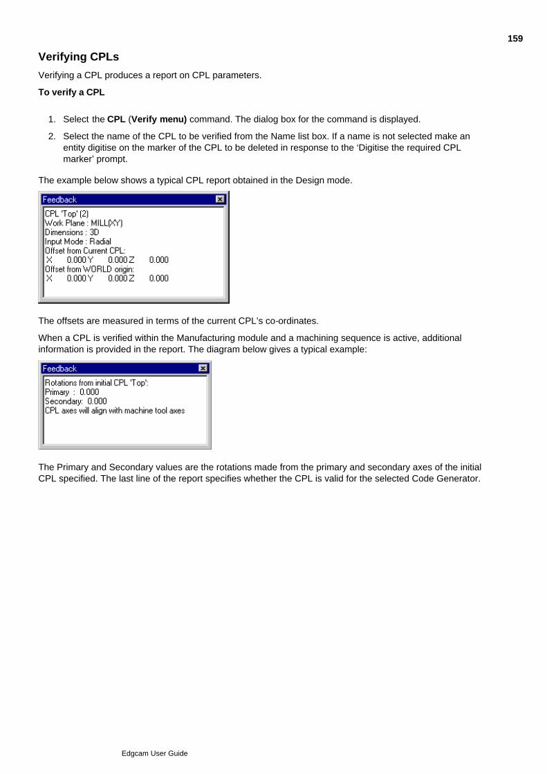
Verifying CPLs
Verifying a CPL produces a report on CPL parameters.
To verify a CPL
Select the CPL (Verify menu) command. The dialog box for the command is displayed.1.
Select the name of the CPL to be verified from the Name list box. If a name is not selected make anentity digitise on the marker of the CPL to be deleted in response to the ‘Digitise the required CPLmarker’ prompt.
2.
The example below shows a typical CPL report obtained in the Design mode.
The offsets are measured in terms of the current CPL’s co-ordinates.
When a CPL is verified within the Manufacturing module and a machining sequence is active, additionalinformation is provided in the report. The diagram below gives a typical example:
The Primary and Secondary values are the rotations made from the primary and secondary axes of the initialCPL specified. The last line of the report specifies whether the CPL is valid for the selected Code Generator.
159
Edgcam User Guide

Deleting CPLs
Only user-defined CPLs can be deleted.
If the currently active CPL is deleted, CPL TOP will become current.
A CPL with an associated machining sequence cannot be deleted.
To delete a CPL
Select the Delete CPL (Edit menu) command.1.
The dialog box for the command is displayed.
Select the name of the CPL to be deleted from the Name list box.2.
Click on OK to continue.3.
160
Edgcam User Guide
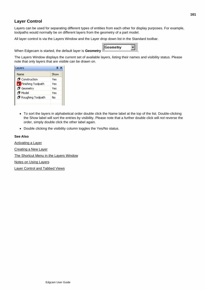
Layer Control
Layers can be used for separating different types of entities from each other for display purposes. For example,toolpaths would normally be on different layers from the geometry of a part model.
All layer control is via the Layers Window and the Layer drop down list in the Standard toolbar.
When Edgecam is started, the default layer is Geometry .
The Layers Window displays the current set of available layers, listing their names and visibility status. Pleasenote that only layers that are visible can be drawn on.
To sort the layers in alphabetical order double click the Name label at the top of the list. Double-clickingthe Show label will sort the entries by visibility. Please note that a further double click will not reverse theorder, simply double click the other label again.
Double clicking the visibility column toggles the Yes/No status.
See Also
Activating a Layer
Creating a New Layer
The Shortcut Menu in the Layers Window
Notes on Using Layers
Layer Control and Tabbed Views
161
Edgcam User Guide
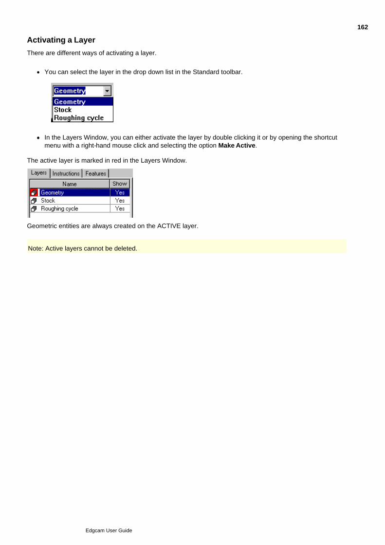
Activating a Layer
There are different ways of activating a layer.
You can select the layer in the drop down list in the Standard toolbar.
In the Layers Window, you can either activate the layer by double clicking it or by opening the shortcutmenu with a right-hand mouse click and selecting the option Make Active.
The active layer is marked in red in the Layers Window.
Geometric entities are always created on the ACTIVE layer.
Note: Active layers cannot be deleted.
162
Edgcam User Guide
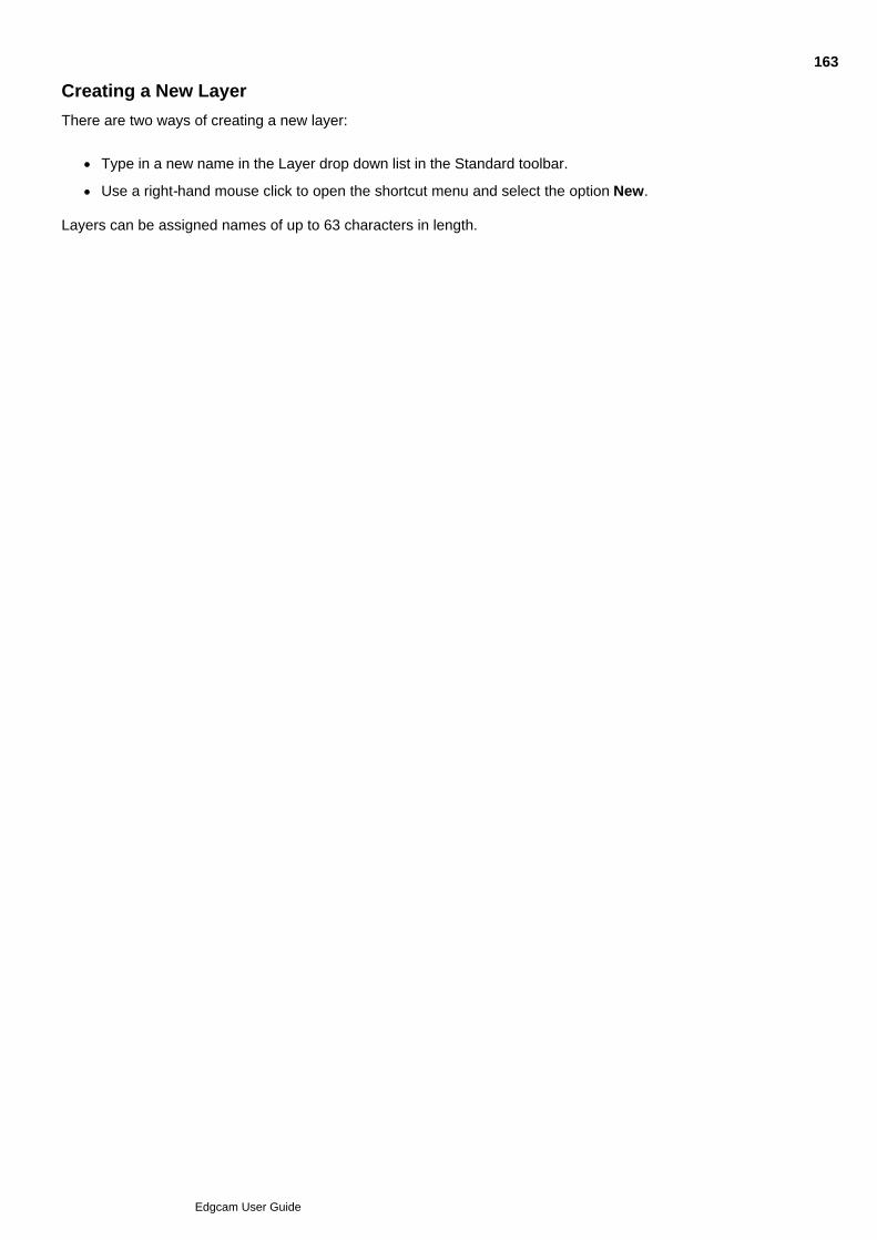
Creating a New Layer
There are two ways of creating a new layer:
Type in a new name in the Layer drop down list in the Standard toolbar.
Use a right-hand mouse click to open the shortcut menu and select the option New.
Layers can be assigned names of up to 63 characters in length.
163
Edgcam User Guide
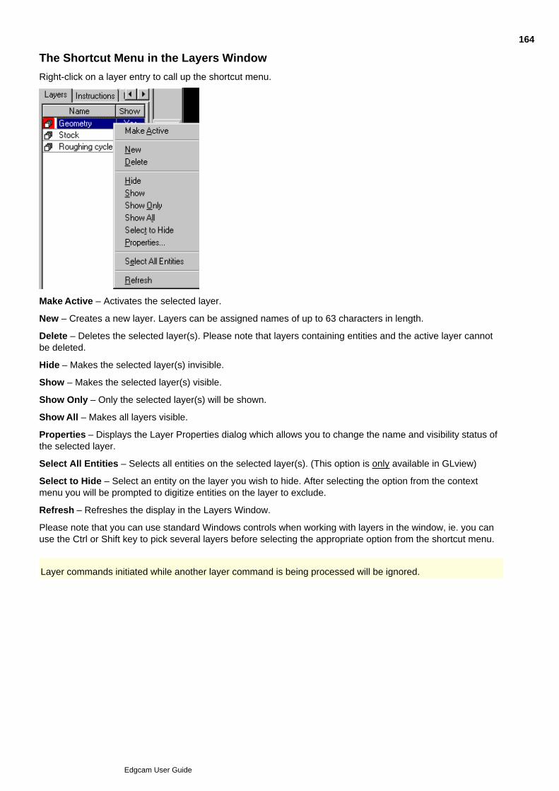
The Shortcut Menu in the Layers Window
Right-click on a layer entry to call up the shortcut menu.
Make Active – Activates the selected layer.
New – Creates a new layer. Layers can be assigned names of up to 63 characters in length.
Delete – Deletes the selected layer(s). Please note that layers containing entities and the active layer cannotbe deleted.
Hide – Makes the selected layer(s) invisible.
Show – Makes the selected layer(s) visible.
Show Only – Only the selected layer(s) will be shown.
Show All – Makes all layers visible.
Properties – Displays the Layer Properties dialog which allows you to change the name and visibility status ofthe selected layer.
Select All Entities – Selects all entities on the selected layer(s). (This option is only available in GLview)
Select to Hide – Select an entity on the layer you wish to hide. After selecting the option from the contextmenu you will be prompted to digitize entities on the layer to exclude.
Refresh – Refreshes the display in the Layers Window.
Please note that you can use standard Windows controls when working with layers in the window, ie. you canuse the Ctrl or Shift key to pick several layers before selecting the appropriate option from the shortcut menu.
Layer commands initiated while another layer command is being processed will be ignored.
164
Edgcam User Guide

Notes on Using Layers
PCIs and numbered layers
Numbered layers from older parts have the prefix 'layer' added to them. For example the layer '77' would beloaded as 'Layer77'.
This might not be compatible with your PCIs, and will be suppressed if the PCI variable ‘NoLayer’ exists withany numeric value (including 0). Note the number will become a string, so numeric operations will fail. Forexample a reference to a range of layers, say 1-7, will try to find a layer called ‘1-7’.
Layers from Inserting Parts
On inserting a part, any layers in the inserted part are imported.
Layers from multiple old parts with the same number will be merged (into a newly prefixed layer name - seeabove).
Layers from multiple newer parts will be renamed to prevent them merging. For example a '.1' suffix will beadded.
Layers for Tools
Creating a Toolchange instruction automatically creates a new layer, on which the tool's toolpaths are placed.
The names are, for example tool.1, tool.2 and so on (these can be changed in the normal way).
Discovering an Entity's Layer
The Entity (Verify menu) command will report back the layer the selected entity can be found on.
165
Edgcam User Guide

About Geometry Creation
There are several stages involved when creating geometric entities. The typical stages are:
In the Menu bar, a toolbar, or the Shortcut menu, click the appropriate command for creating the requiredentity type. This will be a command from the Geometry menu.
1.
Enter parameters into a dialog box to modify the effects of the command. (This stage is usually bypassedby command buttons - making the buttons a quicker option).
2.
Enter co-ordinate data to position the entity, either directly on screen by clicking the mouse (“digitising”)or by entering explicit co-ordinates in a dialog box. Look at the prompts in the Status bar for instructions.
3.
Perform a finish to complete various parts of the command or to complete the command.4.
See AlsoDisplaying the CPL Co-ordinatesFinishing a CommandCompleting a Command accepting Default ParametersEscape Back One Step in the CommandAbort the CommandUndoing/Redoing CommandsConstruction Methods
166
Edgcam User Guide
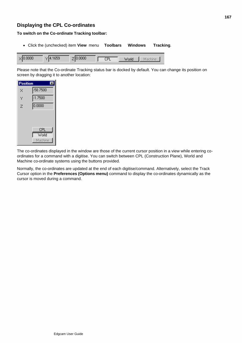
Displaying the CPL Co-ordinates
To switch on the Co-ordinate Tracking toolbar:
Click the (unchecked) item View menu Toolbars Windows Tracking.
Please note that the Co-ordinate Tracking status bar is docked by default. You can change its position onscreen by dragging it to another location:
The co-ordinates displayed in the window are those of the current cursor position in a view while entering co-ordinates for a command with a digitise. You can switch between CPL (Construction Plane), World andMachine co-ordinate systems using the buttons provided.
Normally, the co-ordinates are updated at the end of each digitise/command. Alternatively, select the TrackCursor option in the Preferences (Options menu) command to display the co-ordinates dynamically as thecursor is moved during a command.
167
Edgcam User Guide

Finishing a Command
The help refers to the action ‘Perform a Finish’ when describing how to use certain commands.
You can:
Right-click.
Press the Enter/Return key.
Use the Finish command.
168
Edgcam User Guide

Completing a Command accepting Default Parameters
Selecting the right hand mouse button will finish a command or a part of it. As an alternative to using a singleclick of the right hand mouse button to complete each stage of a command, you can also ‘double click’ thebutton. This will complete the whole command accepting the default settings for the remaining commandoptions.
A typical example where this could be used is the Profile command in Manufacture mode. This commandprompts you to “Digitise new start point for profile chain (or finish)” followed by “Digitise start/end to alter”. If youdouble click the right hand mouse button after selecting the geometry, the system generates the toolpath usingthe default start and end positions, ending the Profile command.
Selecting another command once you have selected the geometry has the same effect as using a double clickof the right hand mouse button.
169
Edgcam User Guide

Escaping Back One Step in the Command
Click the button if you want to move back through one step of data entry when entering data for acommand.
Note that you can also use the Esc key to escape back.
170
Edgcam User Guide

Aborting the Command
Use the Abort command to cancel a command; for example to delete the entities you have just created if youhave made a mistake.
You can click the Abort command button
Alterntively press the F8 key.
If the command has affected the part database, you are asked to confirm the undo.
171
Edgcam User Guide

Creating Lines
Here are the commands for creating lines in the Design toolbar:
Single Line - use to create a line with two digitises
Horizontal Line - use to create a horizontal line with digitises
Vertical Line - use to create a vertical line with digitises
Polyline - use to create a polyline with digitises
Line - use to create a line using parameters in a dialog (this also appears in the Geometry menu).
Note that these commands appear in a combined commands and menu button.
See Also
Inserting Line Data
Selecting Geometry Creation Commands
172
Edgcam User Guide
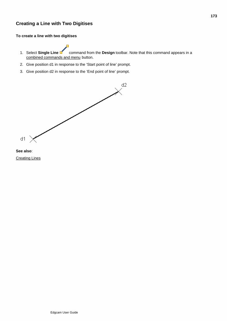
Creating a Line with Two Digitises
To create a line with two digitises
Select Single Line command from the Design toolbar. Note that this command appears in acombined commands and menu button.
1.
Give position d1 in response to the ‘Start point of line’ prompt.2.
Give position d2 in response to the ‘End point of line’ prompt.3.
See also:
Creating Lines
173
Edgcam User Guide

Creating a Horizontal Line
To create a horizontal line
Select the Horizontal Line command from the Design toolbar (note that this command appears ina combined commands and menu button).
1.
Digitise position d1 in response to the ‘Point through which line will pass’ prompt.2.
Digitise position d2 in response to the ‘End point of line’ prompt.3.
The horizontal line ends where it is intersected by a vertical line which passes through d2.
See also:
Creating Lines
174
Edgcam User Guide
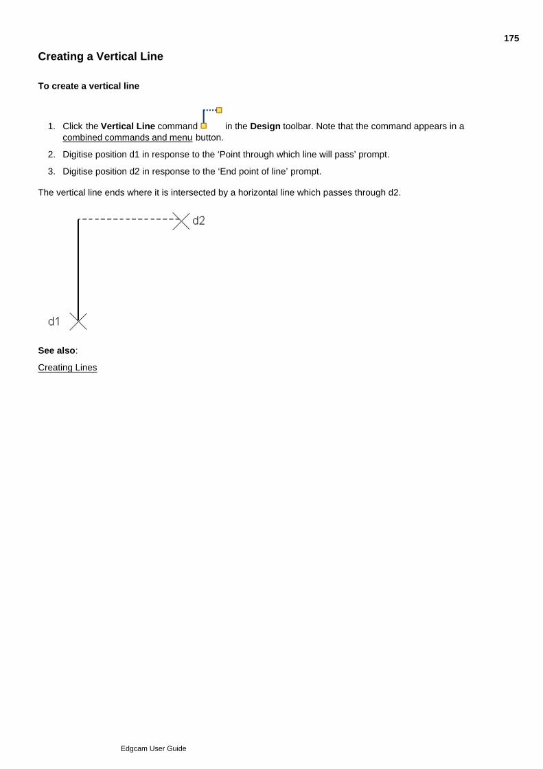
Creating a Vertical Line
To create a vertical line
Click the Vertical Line command in the Design toolbar. Note that the command appears in acombined commands and menu button.
1.
Digitise position d1 in response to the ‘Point through which line will pass’ prompt.2.
Digitise position d2 in response to the ‘End point of line’ prompt.3.
The vertical line ends where it is intersected by a horizontal line which passes through d2.
See also:
Creating Lines
175
Edgcam User Guide

Creating a Polyline
Using Polyline is similar to using Single Line.
The difference is that your digitised end point automatically becomes the start point for a new line, with the Endpoint of line prompt being repeated until you finish the command.
To finish click Escape in the Input toolbar.
Or as a quicker alternative, simply right-click.
176
Edgcam User Guide

Creating a Line using Parameters
Click the Line command in the Geometry menu or Design toolbar.1.
Complete the subsequent Line dialog. See the further information below, and/or click the dialog's Helpbutton for more information.
Note that you for some line type options in the dialog (for example 'Vertical'), you can just check theoption and leave the rest of the settings in their default condition. However this would be the equivalent ofusing the Vertical Line command (for example), which it would be quicker to use directly from the Designtoolbar.
2.
Follow the Status Bar prompts for completing the command. You might have to digitise the 'Point throughwhich line will pass' for example.
3.
More information on the dialog settings:
Polyline
Horizontal
Vertical
Orthogonal
Tangent to Point
Tangent to Tangent
Angle
Relative Angle
Parallel and Parallel 2
Tangent and Angle
To X/Y Co-ordinate
Length
Name
See also
Creating Lines
177
Edgcam User Guide

Inserting Line Data
You can load point data from an ASCII file to create line entities, using the Insert, Point Data (File menu)command.
See Inserting Point Data for details.
178
Edgcam User Guide

Creating Arcs
Here are the commands in the Design toolbar for creating arcs:
Arc - use to create an arc through three points
Radius Arc - use to create an arc by centre point and radius
Arc - use to create an arc using parameters (this command also appears in the Geometry menu).
Note that these commands appear in a combined commands and menu button.
See also
Selecting Geometry Creation Commands
179
Edgcam User Guide
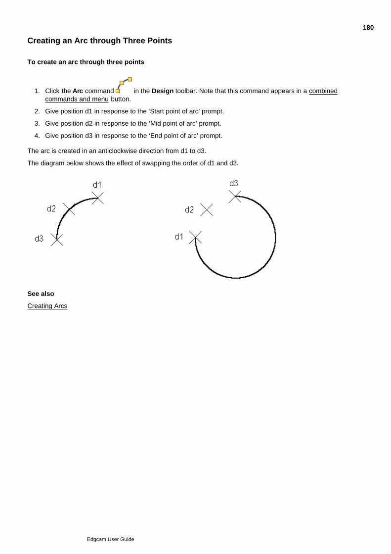
Creating an Arc through Three Points
To create an arc through three points
Click the Arc command in the Design toolbar. Note that this command appears in a combinedcommands and menu button.
1.
Give position d1 in response to the ‘Start point of arc’ prompt.2.
Give position d2 in response to the ‘Mid point of arc’ prompt.3.
Give position d3 in response to the ‘End point of arc’ prompt.4.
The arc is created in an anticlockwise direction from d1 to d3.
The diagram below shows the effect of swapping the order of d1 and d3.
See also
Creating Arcs
180
Edgcam User Guide

Creating an Arc by Centre Point and Radius
To create an arc, specifying the centre point and radius
Click the Radius Arc command in the Design toolbar (note that this appears in a combinedcommands and menu button) . The Arc parameters are displayed.
1.
Enter values as required:2.
Start Angle/End Angle – Specify the angle from the centre of the arc in degrees for the beginning andend points of the arc. If start and end angles are set to <None>, a circle is created.
Radius – Specify the radius of the arc.
Give a location for the centre point in response to the ‘Centre point for arc’ prompt. If any of the arcvalues were set to <Digitise>, you are asked to make digitises to provide this information.
3.
See also
Creating Arcs
181
Edgcam User Guide

Creating an Arc using Parameters
Click the Arc Dialog command in the Design toolbar or the Geometry menu. The parameters forthe Arc command are displayed.
1.
Set up your required command parameters by selecting check boxes and/or typing data into the entryboxes. Note that more than one check box can be selected at any one time and more than one entry boxcan have data typed into it.
2.
Select the OK button to continue with the command. If none of the parameters in the dialog box arechanged from their default settings, the command will have the same function as the Arc button.
3.
Provide the data requested by the prompts in the Status bar.4.
The Arc parameters are:
Blend and Centreline
Blend Through a Point
Blend 3 Entities
Centre Point
Start Angle/End Angle
Radius
Diameter
Tangent to Point
Radius and 2 Points
Blend Radius
Tangent and Centreline
Name
See also
Creating Arcs
182
Edgcam User Guide
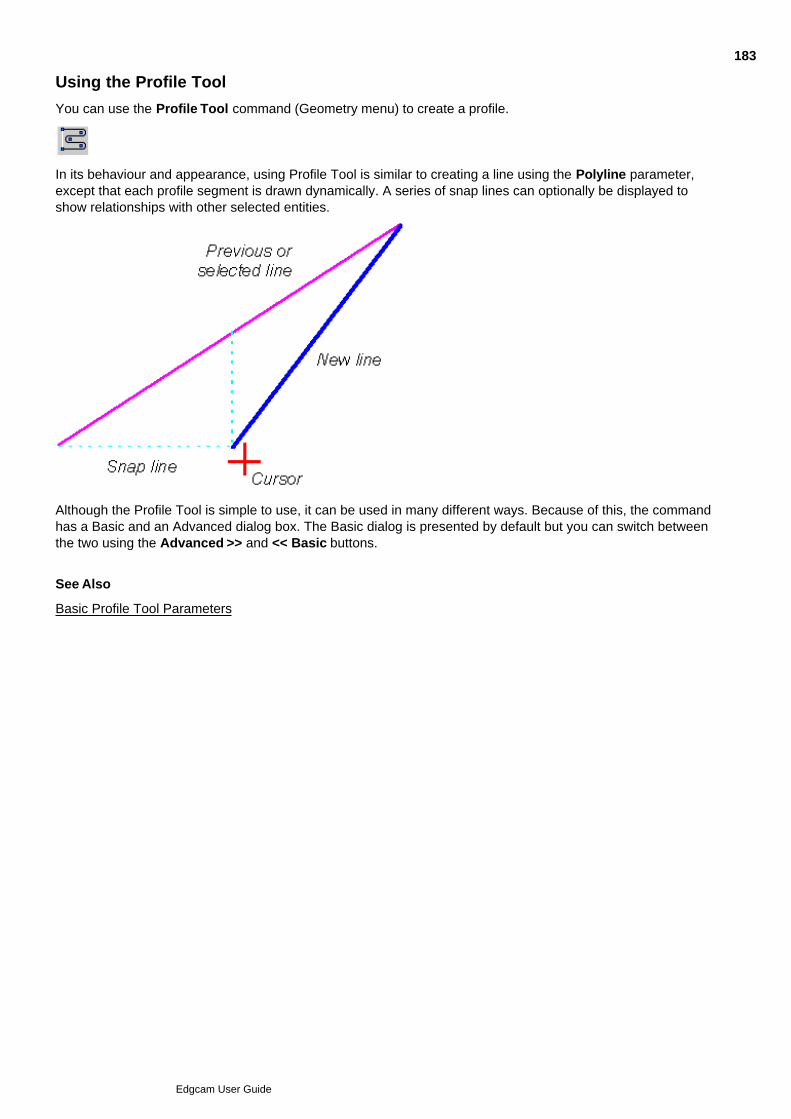
Using the Profile Tool
You can use the Profile Tool command (Geometry menu) to create a profile.
In its behaviour and appearance, using Profile Tool is similar to creating a line using the Polyline parameter,except that each profile segment is drawn dynamically. A series of snap lines can optionally be displayed toshow relationships with other selected entities.
Although the Profile Tool is simple to use, it can be used in many different ways. Because of this, the commandhas a Basic and an Advanced dialog box. The Basic dialog is presented by default but you can switch betweenthe two using the Advanced >> and << Basic buttons.
See Also
Basic Profile Tool Parameters
183
Edgcam User Guide
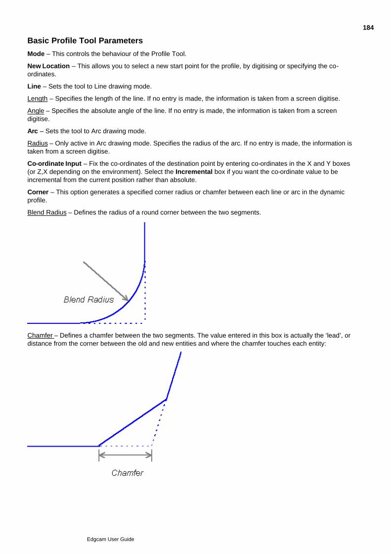
Basic Profile Tool Parameters
Mode – This controls the behaviour of the Profile Tool.
New Location – This allows you to select a new start point for the profile, by digitising or specifying the co-ordinates.
Line – Sets the tool to Line drawing mode.
Length – Specifies the length of the line. If no entry is made, the information is taken from a screen digitise.
Angle – Specifies the absolute angle of the line. If no entry is made, the information is taken from a screendigitise.
Arc – Sets the tool to Arc drawing mode.
Radius – Only active in Arc drawing mode. Specifies the radius of the arc. If no entry is made, the information istaken from a screen digitise.
Co-ordinate Input – Fix the co-ordinates of the destination point by entering co-ordinates in the X and Y boxes(or Z,X depending on the environment). Select the Incremental box if you want the co-ordinate value to beincremental from the current position rather than absolute.
Corner – This option generates a specified corner radius or chamfer between each line or arc in the dynamicprofile.
Blend Radius – Defines the radius of a round corner between the two segments.
Chamfer – Defines a chamfer between the two segments. The value entered in this box is actually the ‘lead’, ordistance from the corner between the old and new entities and where the chamfer touches each entity:
184
Edgcam User Guide

Advanced >> – Click on this button to display the full range of Profile Tool Options. On the new Profile Tooldialog box, this button is replaced by << Basic to return to the Basic Profile Tool dialog box. See Also
Setting the Snap Parameters
Advanced Profile Tool Parameters
185
Edgcam User Guide
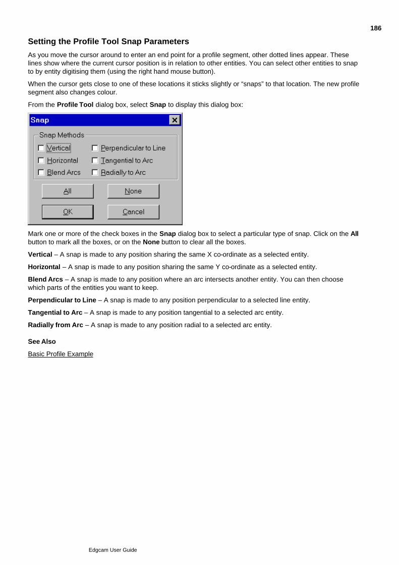
Setting the Profile Tool Snap Parameters
As you move the cursor around to enter an end point for a profile segment, other dotted lines appear. Theselines show where the current cursor position is in relation to other entities. You can select other entities to snapto by entity digitising them (using the right hand mouse button).
When the cursor gets close to one of these locations it sticks slightly or “snaps” to that location. The new profilesegment also changes colour.
From the Profile Tool dialog box, select Snap to display this dialog box:
Mark one or more of the check boxes in the Snap dialog box to select a particular type of snap. Click on the Allbutton to mark all the boxes, or on the None button to clear all the boxes.
Vertical – A snap is made to any position sharing the same X co-ordinate as a selected entity.
Horizontal – A snap is made to any position sharing the same Y co-ordinate as a selected entity.
Blend Arcs – A snap is made to any position where an arc intersects another entity. You can then choosewhich parts of the entities you want to keep.
Perpendicular to Line – A snap is made to any position perpendicular to a selected line entity.
Tangential to Arc – A snap is made to any position tangential to a selected arc entity.
Radially from Arc – A snap is made to any position radial to a selected arc entity. See Also
Basic Profile Example
186
Edgcam User Guide

Basic Profile Example
This example follows through the steps needed to create this profile:
To create a basic profile
Select the Profile Tool (Geometry menu) command. The dialog box is now displayed. If it is not theBasic dialog, click on the Basic button.
1.
Set Line Length to 50 and specify a Corner Chamfer value of 10.2.
Click on Snap.3.
Click on the All button.4.
Click on the Snap tab’s OK button.5.
Click on the Profile Tool dialog’s OK button.6.
Make a digitise to draw the first line segment:7.
Make a second digitise:8.
187
Edgcam User Guide
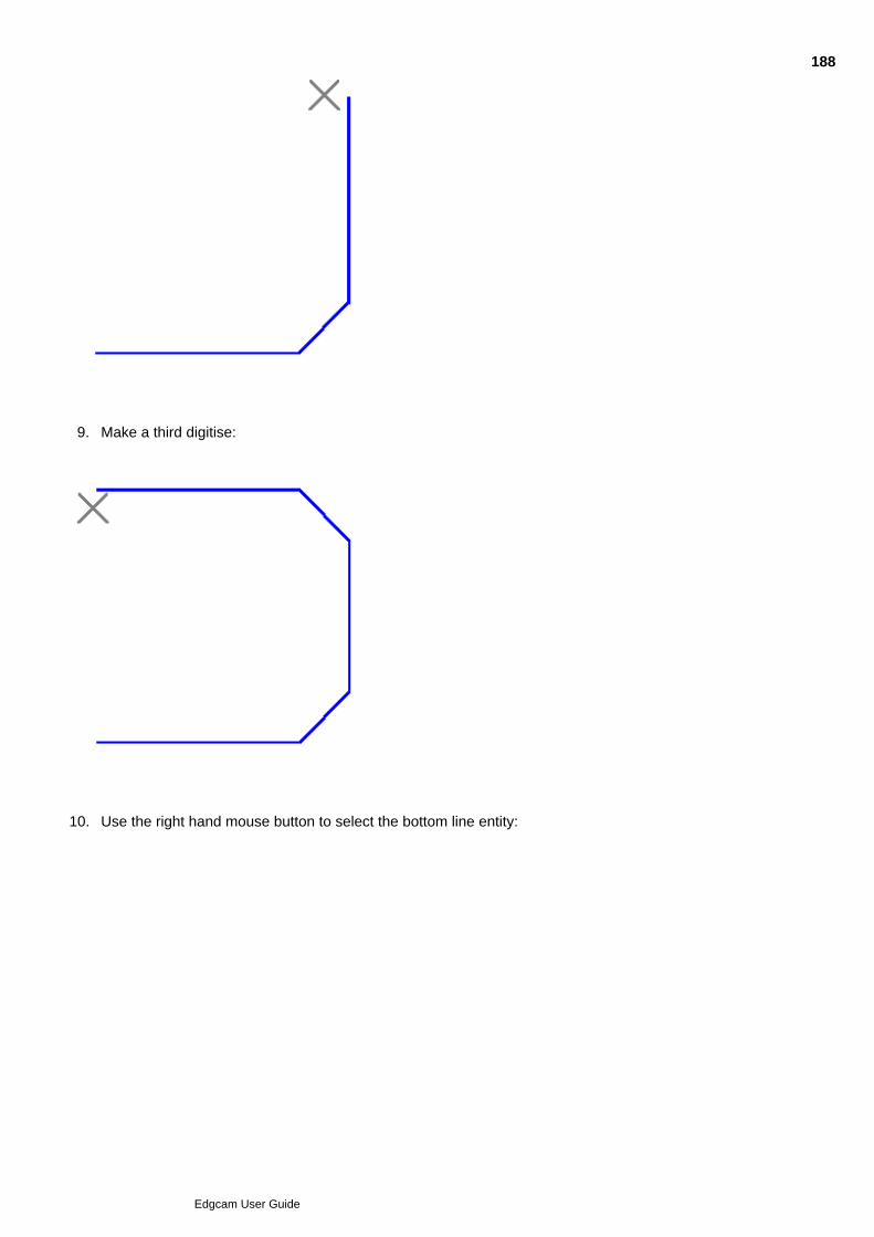
8.
Make a third digitise:9.
Use the right hand mouse button to select the bottom line entity:10.
188
Edgcam User Guide
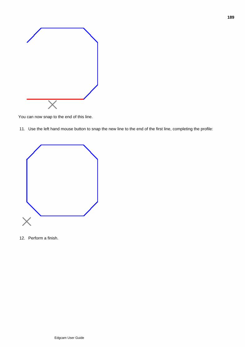
10.
You can now snap to the end of this line.
Use the left hand mouse button to snap the new line to the end of the first line, completing the profile:11.
Perform a finish.12.
189
Edgcam User Guide
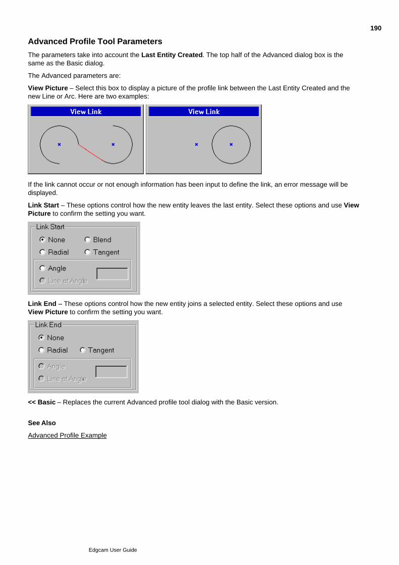
Advanced Profile Tool Parameters
The parameters take into account the Last Entity Created. The top half of the Advanced dialog box is thesame as the Basic dialog.
The Advanced parameters are:
View Picture – Select this box to display a picture of the profile link between the Last Entity Created and thenew Line or Arc. Here are two examples:
If the link cannot occur or not enough information has been input to define the link, an error message will bedisplayed.
Link Start – These options control how the new entity leaves the last entity. Select these options and use ViewPicture to confirm the setting you want.
Link End – These options control how the new entity joins a selected entity. Select these options and useView Picture to confirm the setting you want.
<< Basic – Replaces the current Advanced profile tool dialog with the Basic version.
See Also
Advanced Profile Example
190
Edgcam User Guide
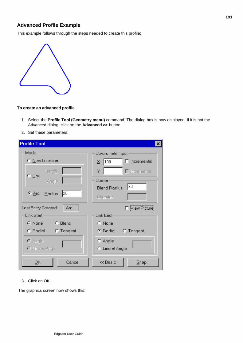
Advanced Profile Example
This example follows through the steps needed to create this profile:
To create an advanced profile
Select the Profile Tool (Geometry menu) command. The dialog box is now displayed. If it is not theAdvanced dialog, click on the Advanced >> button.
1.
Set these parameters:2.
Click on OK.3.
The graphics screen now shows this:
191
Edgcam User Guide
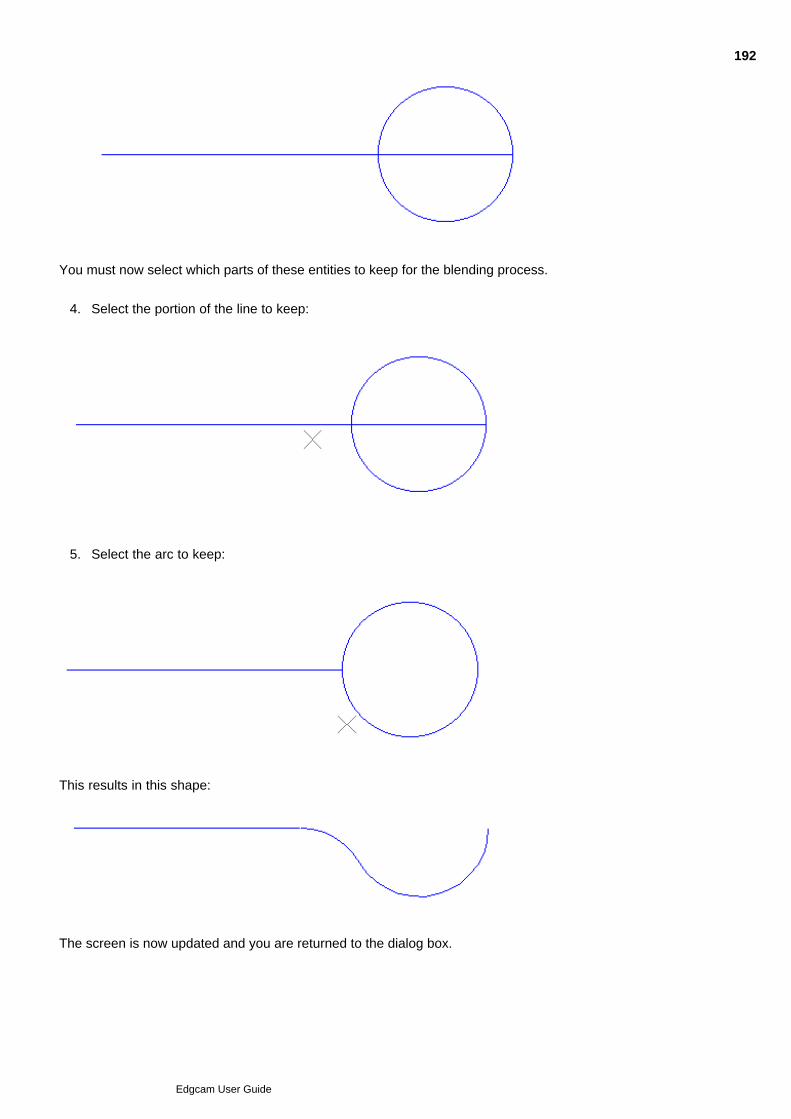
3.
You must now select which parts of these entities to keep for the blending process.
Select the portion of the line to keep:4.
Select the arc to keep:5.
This results in this shape:
The screen is now updated and you are returned to the dialog box.
6.
192
Edgcam User Guide
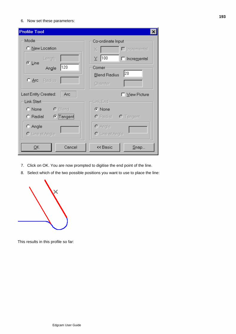
Now set these parameters:6.
Click on OK. You are now prompted to digitise the end point of the line.7.
Select which of the two possible positions you want to use to place the line:8.
This results in this profile so far:
193
Edgcam User Guide
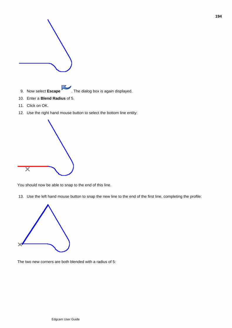
Now select Escape . The dialog box is again displayed.9.
Enter a Blend Radius of 5.10.
Click on OK.11.
Use the right hand mouse button to select the bottom line entity:12.
You should now be able to snap to the end of this line.
Use the left hand mouse button to snap the new line to the end of the first line, completing the profile:13.
The two new corners are both blended with a radius of 5:
194
Edgcam User Guide

Perform a finish.14.
195
Edgcam User Guide

Converting to a Continuous
Use Geometry menu Continuous to create a continuous entity using the dialog below.
(You can also access this help using the cycle dialog's Help button.)
196
Edgcam User Guide

197
Edgcam User Guide

198
Edgcam User Guide
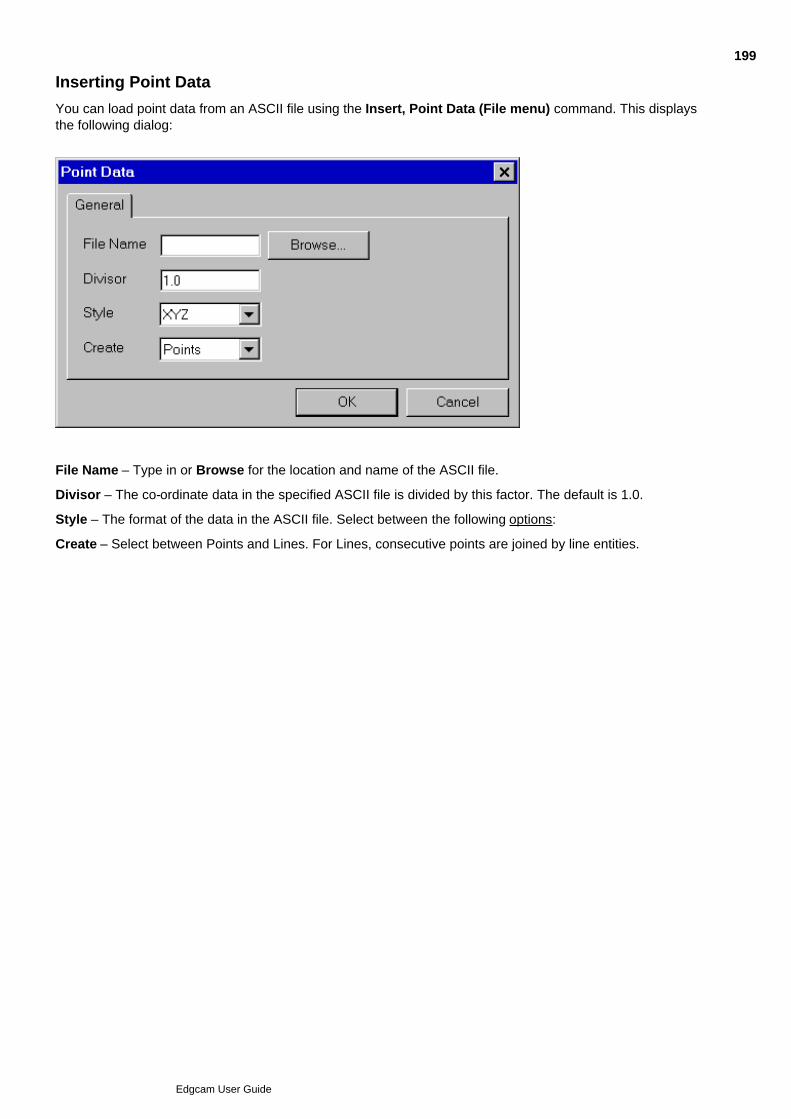
Inserting Point Data
You can load point data from an ASCII file using the Insert, Point Data (File menu) command. This displaysthe following dialog:
File Name – Type in or Browse for the location and name of the ASCII file.
Divisor – The co-ordinate data in the specified ASCII file is divided by this factor. The default is 1.0.
Style – The format of the data in the ASCII file. Select between the following options:
Create – Select between Points and Lines. For Lines, consecutive points are joined by line entities.
199
Edgcam User Guide

Creating Offset Entities
The Offset (Geometry menu) command creates an offset around one or more entities. To create an offset
Select the Offset (Geometry menu) command. The Offset dialog box is displayed.1.
Complete the following parameters as required:2.
Continuous – Select this check box to create a continuous entity from the lines and arcs created bythe offset.
Offset – The distance the new entity will be offset from the original entity.
Type – Controls the creation of entities where two lines meet and the offset will be created on theoutside:
Sharp Corner – Offset lines will be extended to their intersection point.
Round Corner – Inserts a blend radius.
Default Offset Side – Select whether to automatically create the offset on the inside or the outside ofthe original entity (if closed).
Click on OK to continue.3.
Enter one or more digitises in reply to the ‘Line/Arc/Continuous/Group as profile’ prompt. (More than oneentity can be selected to be offset.)
4.
Perform a finish.5.
Edgecam displays an arrow indicating the start point and the side on which the offset will be applied.
If required, digitise a new start point for the profile chain.6.
Perform a finish.7.
The offset(s) are produced.
200
Edgcam User Guide

Creating Group Entities
Use Geometry menu Group to open the dialog below.
(You can also access this help using the cycle dialog's Help button.)
201
Edgcam User Guide

Creating Shapes
Edgecam provides several methods for creating shapes. All shapes are created from a number of individualentities.
Please note that these commands are PDI add-in options and do not support Intellisnap picking. To selectentities you can use either of the following methods:
Select the Entity icon from the Input toolbar
Hold down the right-hand mouse button and select the Entity command from the Shortcut menu
Hold down the Ctrl key
See Also
Creating Rectangles and CuboidsCreating PolygonsCreating Slots
202
Edgcam User Guide

Creating Rectangles and Cuboids
To create a rectangle or a cuboid
Select the Rectangle (Geometry menu) command. The Rectangle parameters are displayed.1.
Complete the parameters:2.
Length – Type in the length of the rectangle or select <Digitise>.
Width – Type in the width of the rectangle or select <Digitise>.
Depth – Type in a value to project the rectangle in the {Z} of the current CPL. Select <Digitise> to beable to specify the depth with a digitise, or select <None> to produce a rectangle rather than a cuboid.
Corner Radius – Enter a radius to produce a rectangle with rounded corners. The default is zerowhich produces 90° corners.
Digitise a point in response to the ‘Select start of rectangle’ prompt.3.
If you did not specify both the length and width, digitise a point in response to the ‘Select end ofrectangle’ prompt.
4.
If you selected Digitise for the depth, make a digitise in another view to specify the depth.5.
To create another rectangle, return to step 3.6.
203
Edgcam User Guide
Creating Polygons
To create a polygon with equal length sides
Select the Polygon (Geometry menu) command. The Polygon parameters are displayed.1.
Complete the parameters, updating default values as required. Note that it is possible to entercontradictory parameters; for example, a side length incompatible with the radius:
2.
Number of sides – Specify the number of sides of equal length in the polygon.
Initial Angle – Specify the absolute angle of the first line of the polygon.
Corner Radius – Enter a radius to produce a polygon with rounded corners.
Depth – Enter a value in this field to project the polygon in the {Z} of the current CPL. Verticals arecreated at each corner, forming a ‘wire frame’ volume.
Type – Select one of the following to define the Dimension parameter:
Side Length – Enter the length of each side in the Dimension parameter.
Inscribed circle – Specify the diameter of the inner construction circle of the polygon in the Dimensionparameter.
Circumscribed – Specify the diameter of the outer construction circle of the polygon in the Dimensionparameter.
Dimension – Enter the size of the dimension specified in the Type field.
Digitise a point in response to the ‘Select start of polygon’ prompt. Depending on the parameters youselected, the polygon is either drawn instantly or you can dynamically position it using the mouse. Adigitise then fixes the polygon’s position.
3.
204
Edgcam User Guide
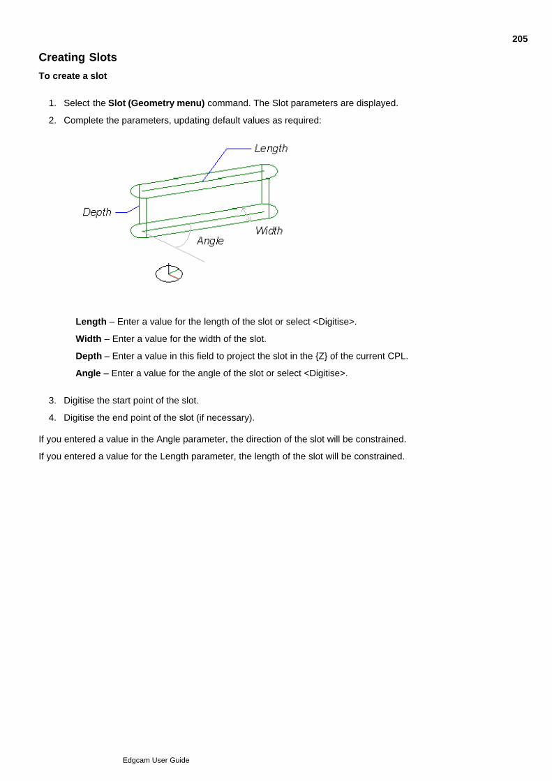
Creating Slots
To create a slot
Select the Slot (Geometry menu) command. The Slot parameters are displayed.1.
Complete the parameters, updating default values as required:2.
Length – Enter a value for the length of the slot or select <Digitise>.
Width – Enter a value for the width of the slot.
Depth – Enter a value in this field to project the slot in the {Z} of the current CPL.
Angle – Enter a value for the angle of the slot or select <Digitise>.
Digitise the start point of the slot.3.
Digitise the end point of the slot (if necessary).4.
If you entered a value in the Angle parameter, the direction of the slot will be constrained.
If you entered a value for the Length parameter, the length of the slot will be constrained.
205
Edgcam User Guide

About Curves
Curves used in design, often referred to as free form curves, are modelled in Edgecam as ‘splines’. The set ofsplines includes the Spline, the Bezier Spline and the B Spline. Given the same source data, each type ofspline gives a curve of a different shape, based on the mathematical equation it is derived from.
The (Geometry menu) commands available to create curves are:
Curves, Spline
Curves, B Spline and Fitted B Spline
Curves, Bezier
Curves, Smooth
Curves, Conic
Curves, Control Points
Curves, Intersection
This example shows the three spline types, using the same set of control points to control each curve'sbehaviour:
206
Edgcam User Guide

About Splines
Here is an example of a spline curve, as defined by (and passing through) six fit points:
Use the Curves, Spline (Geometry menu) command to create spline curves. Also see To create a splinecurve.
A Spline is a smooth curve which passes through each point in a set of data points or fit points. Spline curvesare typically used where accuracy must be maintained at the fit points, but is unnecessary between the fitpoints.
The Spline is made up of a chain of smaller sub-curves. These sub-curves straddle the gaps betweenconsecutive fit points. All but the first and the last fit points form the junction between one sub-curve andanother. At these junctions, the sub-curves are constrained to join together smoothly. The route that a sub-curve takes between one fit point and the next is governed by the Break Points option that you select whencreating the Spline curve.
The Break Points parameter has two options:
Uniform – Uniform break points should only be chosen when the fit points are spaced evenly. An unevenspacing between the fit points results in unwanted loops and wiggles in the path.
Chord Length – This creates a Spline that takes into account the actual distance between the fit points.
Once you have created a Spline, you do not need to retain the construction points as their co-ordinates areretained in the Edgecam definition of the Spline.
You can control the tangent angles at the start and end of the Spline.
The curve segment between each pair of points is defined by three mathematical equations (one for each ofthe x, y and z axes). For example:
x = f(u) = a + bu + cu2 + du3.
Edgecam only creates cubic Splines (of degree 3 – the degree of the equation is the highest value of n in un,so the previous example would be of degree 3). However, Edgecam does support Splines of any order, so youcan import Splines of a higher order from other CAD systems.
207
Edgcam User Guide

Creating Splines
To create a spline curve
Click the Curve Spline Curve command in the Geometry menu.1.
Enter a Tolerance value if required. The smaller the tolerance value, the smoother the curve appears onthe screen. As the curve is mathematically defined, changing this modifier does not alter the actual shapeof the curve.
2.
If required, enter the slope (in degrees) at the start of the curve into the Start Angle. To take the angle ofthe slope from an existing entity, set Start Angle to <Digitise>.
3.
If required, type the slope (degrees) at the end of the curve into the End Angle box. To take the angle ofthe slope from an existing entity, set Start Angle to <Digitise>.
4.
Choose a Break Points option. This can be either Uniform or Chord Length (see About Splines fordetails).
5.
Type a Name for the curve, if required.6.
Digitise the fit points for the curve. The fit points can be full 3D points.7.
The slope angles are measured in an anticlockwise direction from the X axis of the current CPL.
The curve can be altered by using the Entity Data (Edit menu) command.
See Also
About Splines
208
Edgcam User Guide

About B Splines
Here is an example of a B Spline as defined by six control points (note that the first and last points lie on thecurve):
Use the Curves, B Spline (Geometry menu) command. Also see To create a B spline.
A B Spline curve needs a set of control points, but does not necessarily pass through the points. However, italways passes through the first and last points.
(Note that you can use the Curves, Fitted B Spline (Geometry menu) command to create a B Spline using fitpoints rather than control points. In this case the curve passes through each fit point. See also Editing CurvesCreated With Fit Points.)
B Splines are used for general curves where any abrupt changes of the control points will be smoothed.
At the start, the curve is tangential to a line between the first two control points and at its end is tangential to aline between the last two control points. If a single control point is moved, it only changes the curve in thatlocality – other regions of the curve are unaffected.
A feature of the B Spline is the ‘degree’ of the curve. The degree is specified as an integer between 1 and 10.Generally, the lower the degree, the closer the curve will follow the track lines (straight lines between thecontrol points). A degree of 1 produces the track lines themselves. The higher the degree, the flatter the curve.A degree of between 2 and 5 is the most useful in practice, and the default value is 3.
Repeating a control point influences the curve by pulling it sharply towards that point while not reducing its(mathematical) smoothness. The shape of a curve may also be influenced by introducing a different weightingfactor for each control point. Such a curve is called a rational B Spline. A curve created with Edgecam has aweighting of 1.0 assigned to each point and is therefore non-rational.
209
Edgcam User Guide

Creating B Splines
To create a B Spline
Click the Curve B Spline Curve command in the Geometry menu.1.
Type a Tolerance value into the box, if required. The smaller the tolerance value, the smoother the curveappears on the screen. As the curve is mathematically defined, changing this modifier does not alter theactual shape of the curve.
2.
Type the required Degree value into the box. This can be a value between 1 and 10 but it must be lessthan the number of control points. The higher the value, the flatter the curve but it takes longer to create.A value of 3 is adequate for general applications.
3.
Type a Name for the curve, if required.4.
Digitise the control points for the curve.5.
The control points can be full 3D points.
The curve can be altered by using the Entity Data (Edit menu) command. See Also
About B Splines
210
Edgcam User Guide

Creating Fitted B Splines
The Curves, Fitted B Spline (Geometry menu) creates a B Spline curve based on digitised fit points ratherthan control points, so that the curve passes through all the fit points.
Once the fit points have been selected, the command converts them to the equivalent control points. SeeEditing Curves Created With Fit Points for details.
The command uses the same Tolerance, Degree and Name parameters as in the B Spline command, butalso uses these parameters:
Dynamic – Check this box to see the B spline appear on the screen and move around as you digitise existingpoints or screen positions. This allows you to see the effect on the curve as each new point is digitised.
Start Angle – Select the initial direction of the curve from its starting point.
End Angle – Select the final direction of the curve to its end point.
Break Points – Select Uniform or Chord Length break points.
See About Splines for details of details of Start and End Angle and Break Point.
211
Edgcam User Guide

About Bezier Curves
Here is an example of a Bezier curve defined by six control points:
Use the Curves, Bezier (Geometry menu) command. Also see To create a Bezier curve.
Bezier curves are a subset of the more general B Spline curves. Mathematically, a Bezier curve is the same asa B Spline with a degree equal to the number of control points minus 1.
Possible uses for a Bezier curve might be as a simple way of creating a smooth fillet in a profile, or as a ‘bestfit’ approximation amongst control points which you not interested in following too closely, except at the ends ofthe curve.
The useful features of the Bezier curve are:
The start and end positions of the curve are the start and end control points
The start and end curve tangents correspond to the start and end tracks. A start track is the line betweenthe first two control points and the end track is a line between the last two control points.
Internal points influence the curve in the region of the control point.
212
Edgcam User Guide

Creating Bezier Curves
To create a Bezier Curve
Click the Curve Bezier Curve command in the Geometry menu. .1.
Type a Tolerance value into the box, if required. The smaller the tolerance value, the smoother the curveappears on the screen. As the curve is mathematically defined, changing this modifier does not alter theactual shape of the curve.
2.
Type a Name for the curve, if required.3.
Digitise up to 20 control points for the curve.4.
The control points can be full 3D points.
The curve can be altered by using the Entity Data (Edit menu) command.
See Also
About Bezier Curves
213
Edgcam User Guide

About Conic Sections
Use the Curves, Conic (Geometry menu) command.
Conic sections are the shapes produced by taking a slice through a cone.
If the slice is parallel to the sloping side of a cone, the section is a parabola.
If the slice is closer to the vertical the section is a hyperbola.
When the slice approaches the horizontal, the section becomes an ellipse.
A horizontal section gives a circle which is a special case of an ellipse.
Edgecam has two methods for creating a conic section:
Specify positional and tangential information for the ends of the curve, plus a shoulder point to define theform of the curve. The position of this point determines whether the curve is an ellipse, parabola orhyperbola segment.
Specify the centre, the end of the major axis, the height of the ellipse and optional start and end angles ifthe full ellipse is not required.
Also see To create conic sections.
214
Edgcam User Guide
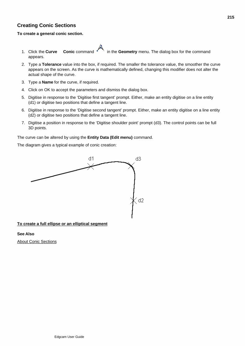
Creating Conic Sections
To create a general conic section.
Click the Curve Conic command in the Geometry menu. The dialog box for the commandappears.
1.
Type a Tolerance value into the box, if required. The smaller the tolerance value, the smoother the curveappears on the screen. As the curve is mathematically defined, changing this modifier does not alter theactual shape of the curve.
2.
Type a Name for the curve, if required.3.
Click on OK to accept the parameters and dismiss the dialog box.4.
Digitise in response to the ‘Digitise first tangent’ prompt. Either, make an entity digitise on a line entity(d1) or digitise two positions that define a tangent line.
5.
Digitise in response to the ‘Digitise second tangent’ prompt. Either, make an entity digitise on a line entity(d2) or digitise two positions that define a tangent line.
6.
Digitise a position in response to the ‘Digitise shoulder point’ prompt (d3). The control points can be full3D points.
7.
The curve can be altered by using the Entity Data (Edit menu) command.
The diagram gives a typical example of conic creation:
To create a full ellipse or an elliptical segment See Also
About Conic Sections
215
Edgcam User Guide

Creating an Ellipse or an Elliptical Element
To create a full ellipse or an elliptical segment
Select the Curves, Conic (Geometry menu) command. The parameters for the command are displayed.1.
Type the start angle (degrees) into the Start Angle box. The angle is measured anticlockwise relative tothe line defining the major axis (d1 to d2).
2.
Type the end angle (degrees) into the End Angle box. The angle is measured anticlockwise relative tothe line defining the major axis (d1 to d2).
3.
Type a Tolerance value into the box, if required. The smaller the tolerance value, the smoother theellipse appears on the screen. As the ellipse is mathematically defined, changing this modifier does notalter its actual shape.
4.
Type a Name for the ellipse, if required.5.
Click on OK to accept the parameters and dismiss the dialog box.6.
Digitise the centre position of the ellipse (d1).7.
Digitise a position defining the length of the major axis (d2).8.
Digitise a position defining the length of the minor axis (d3).9.
The curve can be altered by using the Entity Data (Edit menu) command.
Example
216
Edgcam User Guide

About Smooth Curves
The Curves, Smooth (Geometry menu) command can create a Continuous entity which passes through a setof points and is built up of lines and arcs. Also see To Create a Smooth Curve and Converting to a ContinuousEntity.
Smoothing can produce curves that are visually pleasing rather than mathematically correct.
217
Edgcam User Guide

To Create a Smooth Curve
A smooth curve made up of lines and arcs is created through a set of points. Alternatively, a smooth curvecomprised of lines and arcs can be created to represent an existing Spline.
Select the Curves, Smooth (Geometry menu) command. The parameters for the command aredisplayed.
Select the Continuous check box if a Continuous entity consisting of lines and arcs is to be created. If thischeck box is not selected, lines and arcs will be created as discrete entities.
For a description of the Continuous entity, see Converting to a Continuous Entity.
Type a Tolerance value into the box, if required. The smaller the tolerance value the more lines and arcs arecreated and the smoother the curve will be.
Type a limiting Corner Angle (degrees). As the smoothing process occurs the system will measure the angle ofany bend in the curve. If the angle of the bend is less than or equal to the value specified, it is assumed thatthe bend is actually a deliberate corner. If the angle is greater than the specified value the bend will besmoothed.
In response to the ‘First point/curve (or return)’ prompt: Either make an entity digitise on a spline to beconverted or digitise a start position and continue to provide digitises in response to the ‘Next point/curve (orreturn)’ prompt until the curve is complete.
If the smooth curve is created from data which is not in the current CPL, the lines and arcs forming the smoothcurve will be projected down onto the CPL.
When digitising co-ordinates it is advisable to enter as many positions as possible in areas where there is anabrupt change of direction in the required curve.
218
Edgcam User Guide

Regenerating Control Points
This command regenerates the control points originally used to define a Spline, B Spline or Bezier surface. Thecontrol points can then be used to generate a different surface type.
Select the Curves, Control Points (Geometry menu) command.1.
Digitise a point in response to the ‘Select the curve to generate control points from’ prompt.2.
The control points are displayed.
219
Edgcam User Guide

Generating the Intersection of Two Curves
This command generates points where two entities intersect or approach within a the specified distance (theTolerance).
Select the Curves, Intersection (Geometry menu) command. The Intersection parameter window isdisplayed.
1.
Complete the parameters:2.
Number of steps – The value in this field controls the algorithm used to determine the intersectionpoints. Use a number close to the number of intersection points you expect. If all the intersectionpoints are not found, repeat the command with a higher number.
Tolerance – The maximum distance between the two entities that will count as an intersection for thepurposes of this command.
Digitise a point in response to the ‘Select first curve to intersect’ prompt.3.
Digitise a point in response to the ‘Select second curve to intersect’ prompt.4.
The intersection point(s) are displayed. Note that these points are generated on curves using the mathematicaldefinition of the curve. Depending on the tolerance used to initially define the curve (not the Toleranceparameter used in this command), the points may not appear to lie on the curve.
220
Edgcam User Guide

Creating Text
Use Geometry menu Text to open the dialog below.
(You can also access this help using the cycle dialog's Help button.)
221
Edgcam User Guide

Inserting Text from a File
Use the Text command to open the dialog below.
(You can also access this help using the cycle dialog's Help button.)
222
Edgcam User Guide

About Editing Geometry
Geometry is a general term referring to entities or collections of entities. 'Entities' are lines, arc, points and soon.
To edit geometry you use commands in the Edit menu. (This menu has more commands in Design Mode thanin Manufacture Mode.)
You can also edit the properties of an entity, such as the colour, using a dialog. To open this properties dialogyou can:
Double-click on the entity.
Or click on the entity to select it, then right-click and select Properties from the shortcut menu thatappears.
See Also
Deleting Entities
Trimming Entities
Editing Curves Created With Fit Points
223
Edgcam User Guide

Deleting Entities
Use the Delete button to digitise any entities that you want to delete.
If you use the Delete (Edit menu) button, you can use one parameter:
Match Colour – Check this box if you want to delete entities of a colour matching that shown on the Standardtoolbar.
224
Edgcam User Guide

Trimming Entities
The Trim (Edit menu) command allows you to trim or break lines, arcs, continui and curves. Note that "trim"will extend an entity to the intersection point or truncate it back to that point as appropriate. The commandoffers the following options:
Trimming one entity against another
Trimming two intersecting entities
Breaking an entity
Trimming many entities against one entity
When trimming entities that lie in different CPLs the trimming will be in respect to the current CPL.
Entities other than lines and arcs are converted to B-splines when trimmed, e.g. trimming a continuousconsisting of lines and arcs will convert the continuous into a b-spline (entity number will not change).
Curves can only be trimmed, not extended.When breaking a curve it will be split into two separate curves. The curves will maintain their curvaturecompared to the original curve. When only one entity is selected to break a curve the curve is split into two andthey will meet at the intersection point.
225
Edgcam User Guide
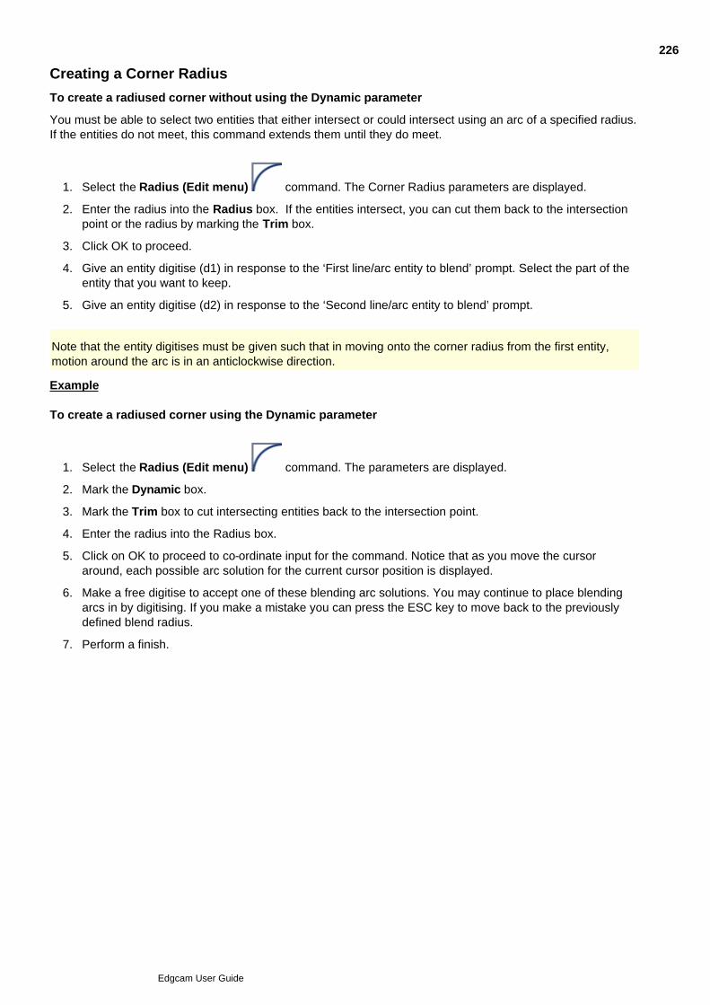
Creating a Corner Radius
To create a radiused corner without using the Dynamic parameter
You must be able to select two entities that either intersect or could intersect using an arc of a specified radius.If the entities do not meet, this command extends them until they do meet.
Select the Radius (Edit menu) command. The Corner Radius parameters are displayed.1.
Enter the radius into the Radius box. If the entities intersect, you can cut them back to the intersectionpoint or the radius by marking the Trim box.
2.
Click OK to proceed.3.
Give an entity digitise (d1) in response to the ‘First line/arc entity to blend’ prompt. Select the part of theentity that you want to keep.
4.
Give an entity digitise (d2) in response to the ‘Second line/arc entity to blend’ prompt.5.
Note that the entity digitises must be given such that in moving onto the corner radius from the first entity,motion around the arc is in an anticlockwise direction.
Example To create a radiused corner using the Dynamic parameter
Select the Radius (Edit menu) command. The parameters are displayed.1.
Mark the Dynamic box.2.
Mark the Trim box to cut intersecting entities back to the intersection point.3.
Enter the radius into the Radius box.4.
Click on OK to proceed to co-ordinate input for the command. Notice that as you move the cursoraround, each possible arc solution for the current cursor position is displayed.
5.
Make a free digitise to accept one of these blending arc solutions. You may continue to place blendingarcs in by digitising. If you make a mistake you can press the ESC key to move back to the previouslydefined blend radius.
6.
Perform a finish.7.
226
Edgcam User Guide
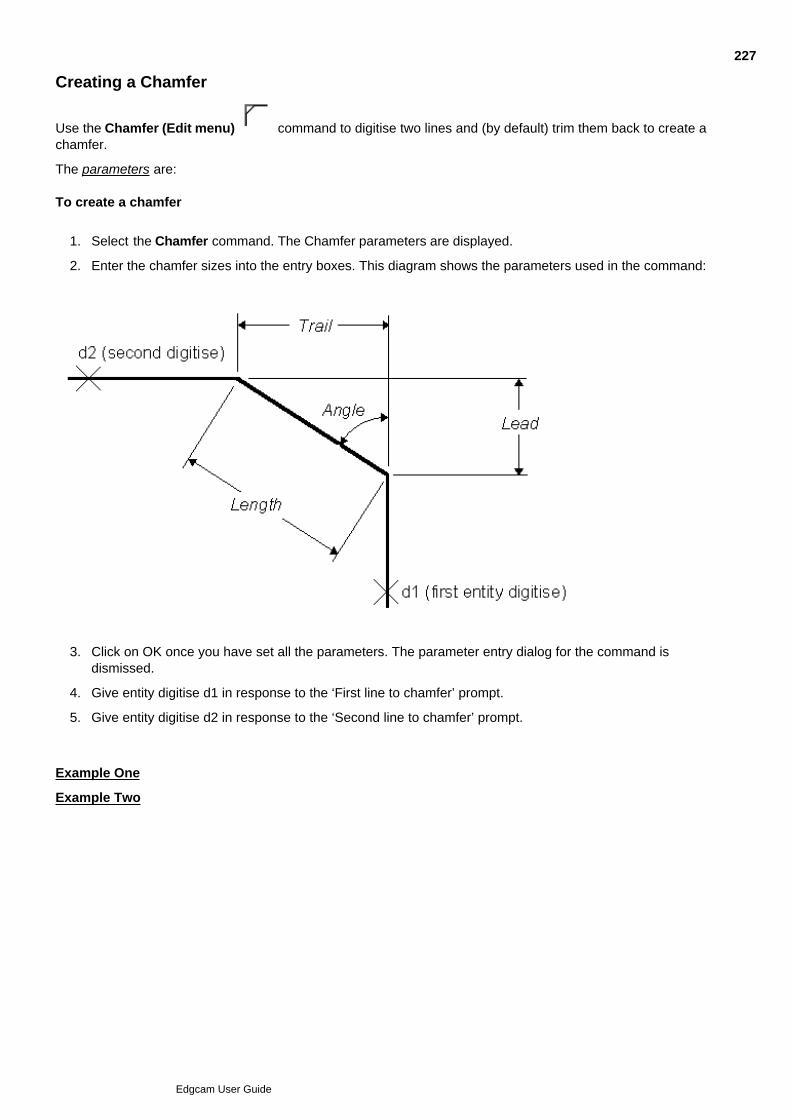
Creating a Chamfer
Use the Chamfer (Edit menu) command to digitise two lines and (by default) trim them back to create achamfer.
The parameters are: To create a chamfer
Select the Chamfer command. The Chamfer parameters are displayed.1.
Enter the chamfer sizes into the entry boxes. This diagram shows the parameters used in the command:2.
Click on OK once you have set all the parameters. The parameter entry dialog for the command isdismissed.
3.
Give entity digitise d1 in response to the ‘First line to chamfer’ prompt.4.
Give entity digitise d2 in response to the ‘Second line to chamfer’ prompt.5.
Example One
Example Two
227
Edgcam User Guide

Transforming Solids with Features
You can use the Edit menu Transform commands to transform (translate, rotate etc) solid geometry. (Manyof these commands are also in the Solids toolbar.)
If you transform a solid with features, the features are also transformed.
However the transformation will only complete if the features stay in their CPL:
For mill features, you can translate along any axis, and rotate about the Z axis of the feature's CPL.
For Turn features, you cannot rotate out of the ZX plane.
For Radial hole features, the 'Axis' property indicates the X, Y or Z axis of the feature's CPL that you cantranslate along, or rotate around.
With the 'Copy' option checked, the command will always complete to create the copy, but without anyfeatures transformed out of their CPL..
Thread information will be preserved after transformation, unless the threaded hole features are modified, inwhich case the thread information will be removed on a reload.
228
Edgcam User Guide

Creating Mirror Images
Use Edit menu Transform Mirror to open the dialog below.
(You can also access this help using the cycle dialog's Help button.)
229
Edgcam User Guide

Projecting Entities
Use Edit menu Transform Project to open the dialog below.
(You can also access this help using the cycle dialog's Help button.)
230
Edgcam User Guide

Rotating Entities
Use Edit menu Transform Rotate to open the dialog below.
(You can also access this help using the cycle dialog's Help button.)
231
Edgcam User Guide

Scaling Entities
Use Edit menu Transform Scale to open the dialog below.
(You can also access this help using the cycle dialog's Help button.)
232
Edgcam User Guide

Stretching Entities
Classic Edgecam View only
Use Edit menu Transform Stretch to open the dialog below.
(You can also access this help using the cycle dialog's Help button.)
233
Edgcam User Guide

Translating Entities
Use Edit menu Transform Translate to open the dialog below.
(You can also access this help using the cycle dialog's Help button.)
234
Edgcam User Guide
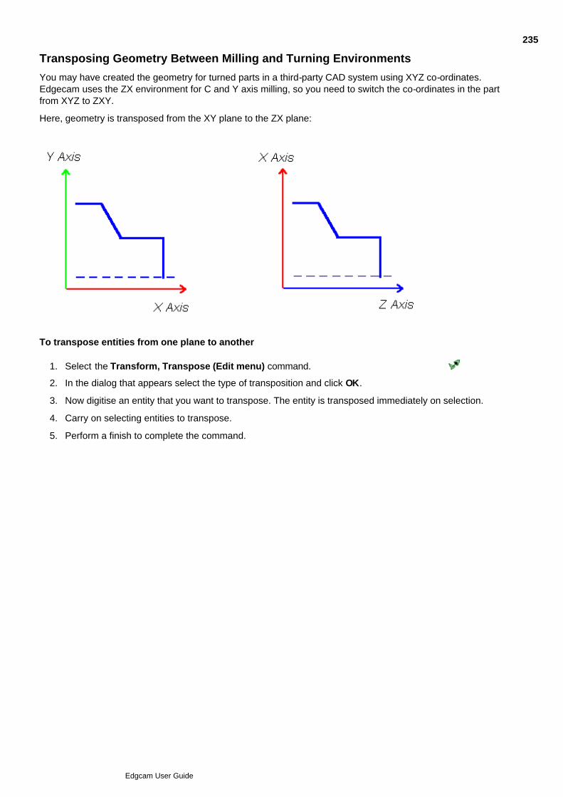
Transposing Geometry Between Milling and Turning Environments
You may have created the geometry for turned parts in a third-party CAD system using XYZ co-ordinates.Edgecam uses the ZX environment for C and Y axis milling, so you need to switch the co-ordinates in the partfrom XYZ to ZXY.
Here, geometry is transposed from the XY plane to the ZX plane:
To transpose entities from one plane to another
Select the Transform, Transpose (Edit menu) command.1.
In the dialog that appears select the type of transposition and click OK.2.
Now digitise an entity that you want to transpose. The entity is transposed immediately on selection.3.
Carry on selecting entities to transpose.4.
Perform a finish to complete the command.5.
235
Edgcam User Guide

Transforming Stock and Fixtures
On stock and fixtures you can use:
Edit menu Transform TranslateEdit menu Transform RotateEdit menu Transform Mirror (apart from solid stock or fixtures)Edit menu Transform Scale
As well as selecting stock and fixtures by digitising, you can also select them in the Features Window.
236
Edgcam User Guide

Editing Curves Created With Fit Points
When editing a curve that was created using fit points rather than control points, you may achieve anunexpected result.
Note that:
Fit points ensure that the curves go through the points you specify.
Control points control the shape of the entity, depending on the mathematical equation used to createthe entity.
When you use fit points to create a curve, Edgecam calculates the control points from the digitised fit pointsand the degree parameter, and stores the control points. The fit point information is discarded.
Subsequently, if you edit the curve using the Entity Edit Data command, it is treated as though it was createdusing control points. If you change the Degree parameter, the entity may not necessarily go through the originalfit points.
237
Edgcam User Guide
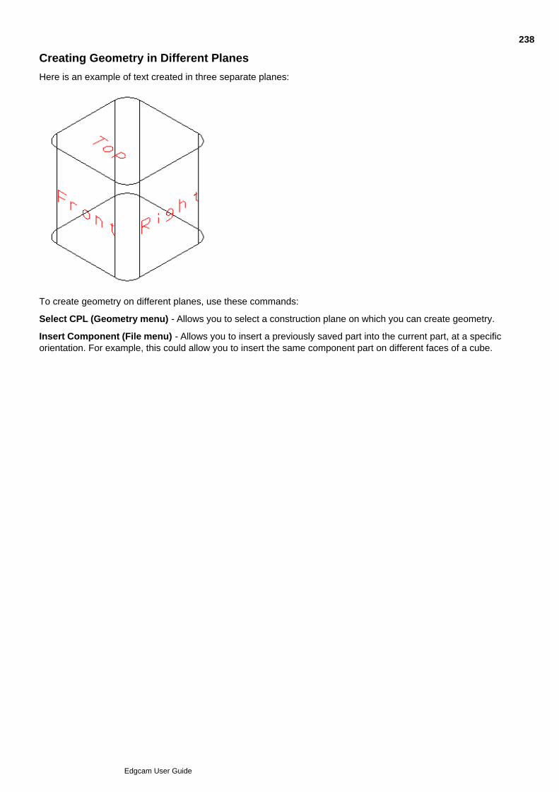
Creating Geometry in Different Planes
Here is an example of text created in three separate planes:
To create geometry on different planes, use these commands:
Select CPL (Geometry menu) - Allows you to select a construction plane on which you can create geometry.
Insert Component (File menu) - Allows you to insert a previously saved part into the current part, at a specificorientation. For example, this could allow you to insert the same component part on different faces of a cube.
238
Edgcam User Guide

About Surfaces
Edgecam supports many different surface definitions. Surfaces are complex, but the tools within Edgecamsimplify their creation and use.
You can work with surfaces using the Surfaces category commands, in the Surfaces toolbar.
You can also input surface data (from which the surfaces are calculated):
Through specialist application programs such as PDI macros which input data directly from co-ordinatemeasuring systems. See PDI - Customising with PCIs and PDIs.
From third party programs, typically using IGES or VDA-FS interface formats.
Surface models can be represented by several different surface types; for example, a half cylinder could beconstructed from a revolution, tabulated cylinder, ruled surface, coons patch or flowed surface.
When considering which surface type to use, bear in mind:
What sort of data you are starting with.
The accuracy of this data.
How you want to machine the surface.
You should read about each surface type Edgecam supports to establish which is the best surface type to usefor your application. In some situations there may only be one valid choice, however.
In the case of the half cylinder, a surface of revolution usually works better than a coons patch, since it is asimpler mathematical representation and so Edgecam can generate the toolpath faster. See Also
Typical Uses for Surfaces
Creating Functional Surface Types
Creating Aesthetic Surface Types
Creating More Surface Types
Working with Surface Curves
Altering Existing Surfaces
239
Edgcam User Guide
Typical Uses for Surfaces
Surfaces are used in the design of a wide range of objects. Some typical uses are discussed in this section.
Moulds
Moulds are usually, but not exclusively, created using accurate data and are therefore drawn using functionalsurface types. They are usually produced in two halves so that the finished article can be removed easily fromthe mould. Moulds are usually drawn complete and then split.
Although there is often an obvious place for the split, this is not always the case, especially for complex orirregularly shaped moulds. Edgecam can automatically decide where the split line(s) should go. A mould canbe split into more than two parts if necessary.
See Generating Split Lines.
Aerospace Parts
These parts are generated from functional surfaces, as the data for these surfaces are calculated exactly andmust be strictly adhered to.
“Lofting” is a technique commonly used when designing boats, aircraft wings and other aerodynamic surfacesand for turbine blades (whether jet, wind or water turbine blades).
This is where a part is reconstructed from cross sections taken from an original model. These cross sectionsare usually spline curves.
Woodworking
Woodworking includes wooden and plastic parts machined directly into material, often involving trimming anddeflashing.
In general these are functional parts but there may be an aesthetic requirement (for example, woodenhousehold objects such as bowls or lamp bases).
Automotive Parts
Parts for the automotive industry are both functional (such as engine parts) and aesthetic (for example, wingpanels, using Bezier and B Spline surfaces). Similar techniques are used as for aeronautical parts.
See Also
Interfacing to Other CAD Systems
Defining Surfaces in Parametric (U, V) Space
Viewing Surfaces
Using UV Markers
Displaying Surface Normals
Verifying Surface Normals
Defining Surface Curves
240
Edgcam User Guide

Interfacing to Other CAD Systems
Most CAD systems represent all surface types as B Splines. This is because they then only have to handle onesurface type. These are usually NURBS (Non-Uniform Rational B-Splines).
Edgecam supports NURBS through importing and exporting IGES format files. Surfaces created withinEdgecam do not use NURBS.
241
Edgcam User Guide

Defining Surfaces in Parametric (U, V) Space
Every point on an Edgecam surface is defined in terms of a 2-axis co-ordinate system. The axes of this systemare called U and V. All co-ordinate values range from 0 to 1.
The U, V co-ordinate system is related to the World Axes (the x, y, z co-ordinate system) by three functionsinvolving the u and v co-ordinates, or parameters, in “parametric space”, as follows:
x co-ordinate = X(u,v)
y co-ordinate = Y(u,v)
z co-ordinate = Z(u,v)
The exact function or mapping depends on the surface type (you do not need to know the exact mappingfunctions to use surfaces in Edgecam!).
Therefore, for every point in parametric space, there is a corresponding point in World Space, although thereverse is not true. This simply means that although every point on a given surface exists in World Space, notevery point in World Space is located on this surface.
This diagram shows the same surface in both world and parametric space.
There are several reasons why it is convenient to use parametric space for surfaces:
Any point on the surface can be specified uniquely by a (u, v) pair.
All surface types can be treated in the same way by surface manipulation functions; for example, anysurface type can be intersected or trimmed against any other. This is not the case with some CAD/CAMpackages, which do not allow intersection between certain surface type combinations.
Parameter lines of constant u or v generally follow the contours of the surface. For this reason, it is oftenconvenient to machine a surface by moving the tool in a constant U or V direction.
242
Edgcam User Guide
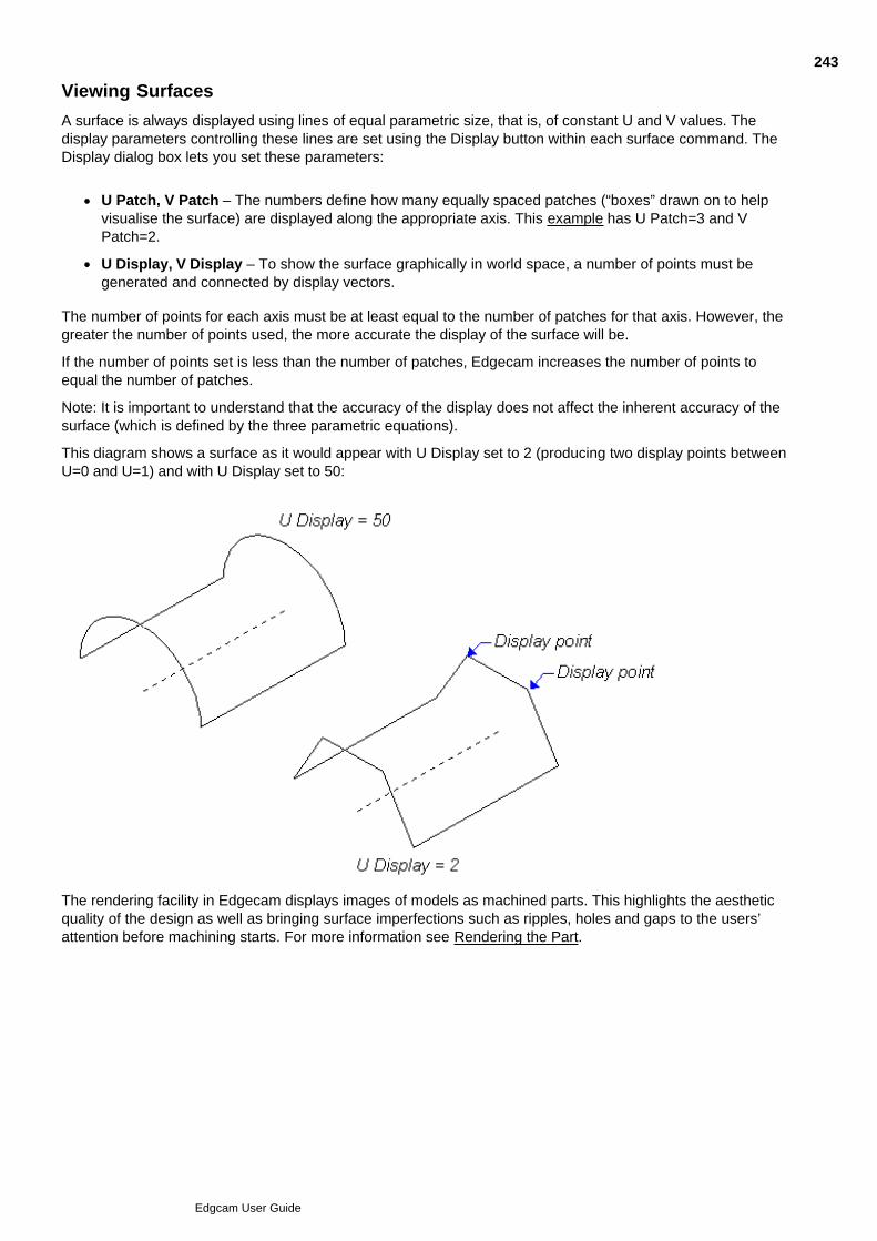
Viewing Surfaces
A surface is always displayed using lines of equal parametric size, that is, of constant U and V values. Thedisplay parameters controlling these lines are set using the Display button within each surface command. TheDisplay dialog box lets you set these parameters:
U Patch, V Patch – The numbers define how many equally spaced patches (“boxes” drawn on to helpvisualise the surface) are displayed along the appropriate axis. This example has U Patch=3 and VPatch=2.
U Display, V Display – To show the surface graphically in world space, a number of points must begenerated and connected by display vectors.
The number of points for each axis must be at least equal to the number of patches for that axis. However, thegreater the number of points used, the more accurate the display of the surface will be.
If the number of points set is less than the number of patches, Edgecam increases the number of points toequal the number of patches.
Note: It is important to understand that the accuracy of the display does not affect the inherent accuracy of thesurface (which is defined by the three parametric equations).
This diagram shows a surface as it would appear with U Display set to 2 (producing two display points betweenU=0 and U=1) and with U Display set to 50:
The rendering facility in Edgecam displays images of models as machined parts. This highlights the aestheticquality of the design as well as bringing surface imperfections such as ripples, holes and gaps to the users’attention before machining starts. For more information see Rendering the Part.
243
Edgcam User Guide
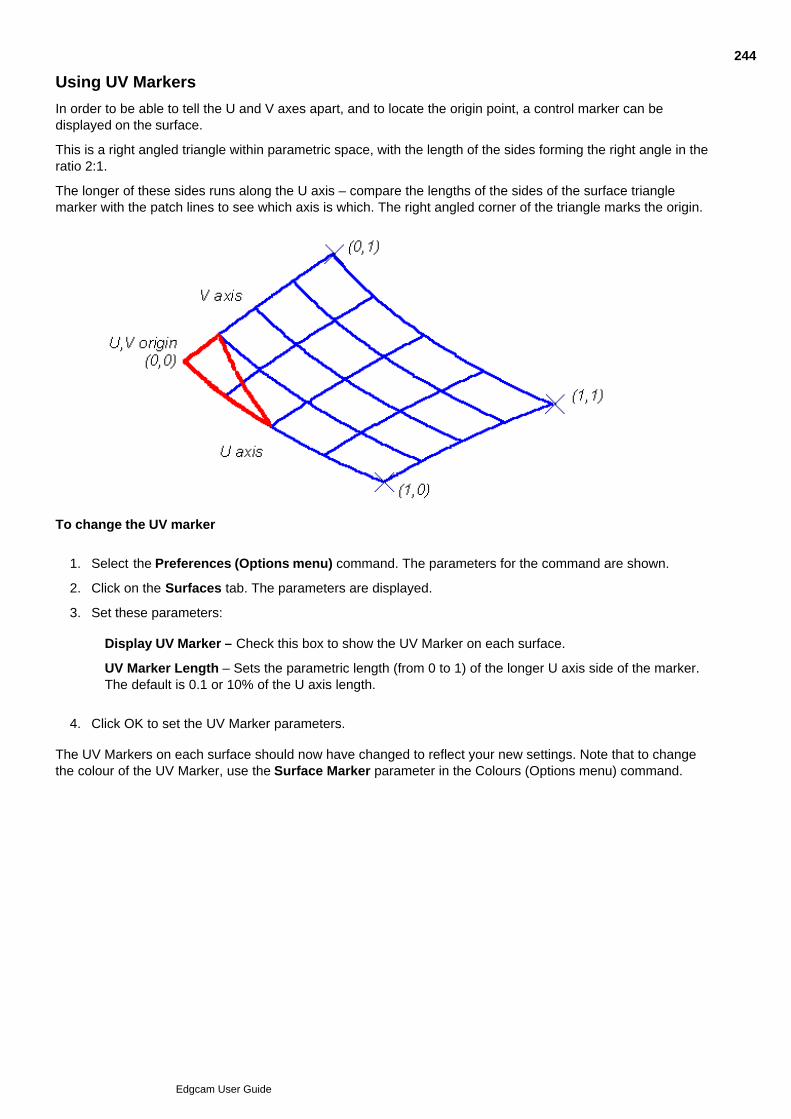
Using UV Markers
In order to be able to tell the U and V axes apart, and to locate the origin point, a control marker can bedisplayed on the surface.
This is a right angled triangle within parametric space, with the length of the sides forming the right angle in theratio 2:1.
The longer of these sides runs along the U axis – compare the lengths of the sides of the surface trianglemarker with the patch lines to see which axis is which. The right angled corner of the triangle marks the origin.
To change the UV marker
Select the Preferences (Options menu) command. The parameters for the command are shown.1.
Click on the Surfaces tab. The parameters are displayed.2.
Set these parameters:3.
Display UV Marker – Check this box to show the UV Marker on each surface.
UV Marker Length – Sets the parametric length (from 0 to 1) of the longer U axis side of the marker.The default is 0.1 or 10% of the U axis length.
Click OK to set the UV Marker parameters.4.
The UV Markers on each surface should now have changed to reflect your new settings. Note that to changethe colour of the UV Marker, use the Surface Marker parameter in the Colours (Options menu) command.
244
Edgcam User Guide

Displaying Surface Normals
Sometimes the only way to check the fairness of a surface (if for example, you imported the surface from athird-party CAD system) is to examine the surface normals. You can control how these lines appear by usingthe Surfaces tab in the Preferences (Options menu) command.
To display the surface normals
Select the Preferences (Options menu) command. The parameters for the command are shown.1.
Click on the Surfaces tab. The parameters are displayed.2.
Set these parameters:3.
Display Normals – Check this box to display lines representing the normals to each surface.
Normal Length – Sets the length of each surface normal. These will therefore appear consistent foreach surface.
Click OK to set the surface normal parameter selections.4.
Click OK to exit the command.5.
The surface normals should now change to reflect your new settings. Note that the surface normals appear atthe intersection points of the patch lines on a surface.
245
Edgcam User Guide

Verifying Surface Normals
Rather than displaying surface normals constantly using the System command, you can use the SurfaceNormals (Verify menu) command to display one or more surface normals on a selected surface.
U/V Parameter – These control how the surface normals are displayed:
Leave both parameters blank to display surface normals at the intersection points of the patch lines onthe digitised surface.
Enter a value from 0 to 1 for one parameter to display normals at the intersection points of the specifiedco-ordinate and the patch lines on the digitised surface.
Enter values for both parameters to display a single normal at the specified co-ordinates on the digitisedsurface.
In all cases the surface normal(s) will only remain until the screen is redrawn for any reason.
246
Edgcam User Guide

Defining Surface Curves
A surface curve is a set of (u, v) parameter pairs defining a series of points lying on a surface.
Unlike surfaces, surface curves do not have precise mathematical definitions, but are defined by the number ofpairs of points.
A surface curve can be produced in two ways:
The intersection of two surfaces can be used to generate a surface curve. The number of points on thecurve is determined by the tolerance set.
A surface curve is generated when an entity is projected onto a surface. In Design mode, lines, arcs,curves and text can be projected to produce surface curves. (In Manufacturing mode, only toolpaths canbe projected, producing a toolpath entity.)
Although a surface curve may exist only on a surface, it can be converted into an entity in its own right, by‘exploding’ it into a 3D Spline curve. Each point on the surface curve becomes a control point for the Spline.
247
Edgcam User Guide
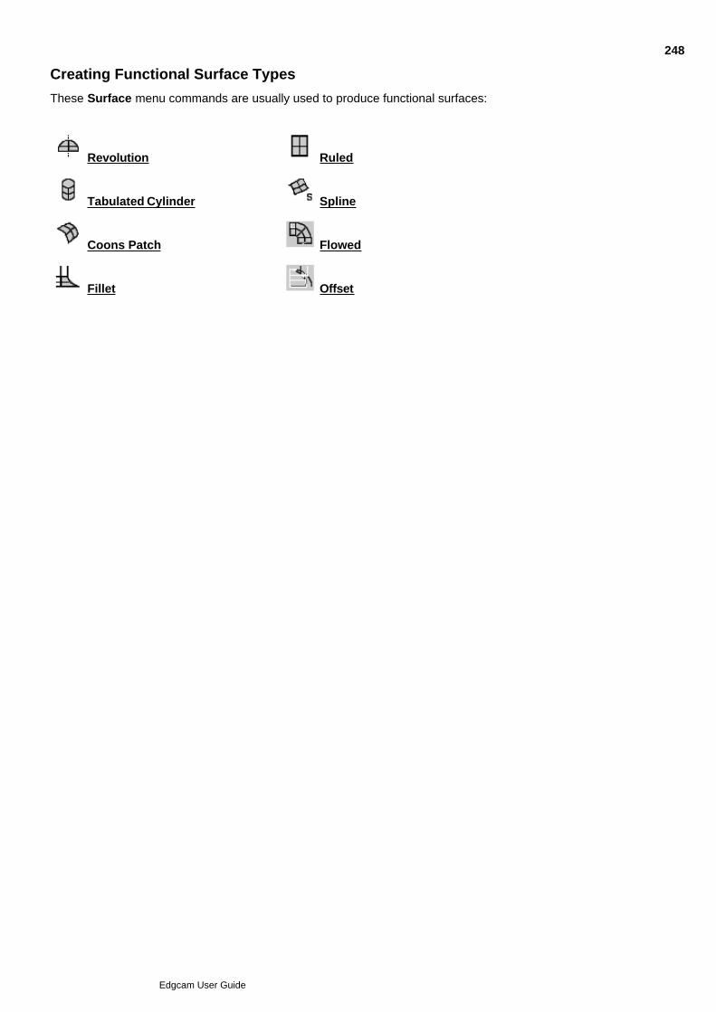
Creating Functional Surface Types
These Surface menu commands are usually used to produce functional surfaces:
Revolution Ruled
Tabulated Cylinder Spline
Coons Patch Flowed
Fillet Offset
248
Edgcam User Guide

Creating Surfaces of Revolution
A surface of revolution created by moving one selected entity around an axis (another selected entity). A typicaluse of surfaces of revolution is to create cones, by sweeping an entity about a vertical axis which shares acommon end point.
Surfaces of Revolution can be created using the Revolution (Surface menu) command. The properties of aSurface of Revolution can be altered using the Entity Data (Edit menu) command.
To create a surface of revolution
Select the button from the Surface toolbar or the Revolution (Surface menu) command. Thedialog box for the command is displayed.
1.
Enter the Start and End Angles. These are the angles of the start and end points on the arc ofrevolution.
2.
Enter a name for the surface, if required.3.
Select Display to set the surface display parameters. The Display parameters now appear.4.
Enter the required number of patches in the U and V directions into the U Patch and V Patch boxesrespectively.
5.
Enter the required number of display points in the U and V directions into the U Display and V Displayboxes respectively.
6.
Click OK to accept the parameters for the command.7.
Enter a digitise in response to the ‘Digitise entity to be swept to form surface’ prompt.8.
Enter a digitise in response to the ‘Digitise entity to form axis or rotation’ prompt.9.
Continue from step 8 again or perform a finish.10.
Click here to view an example surface of revolution.
249
Edgcam User Guide

Creating Ruled Surfaces
A ruled surface requires two boundary or edge entities (lines, arcs or curves). Any point on the first entity isrelated by a straight line to a point in the same reference position on the second entity.
Click here to see four views of a ruled surface:
Ruled surfaces can be created using the Ruled (Surface menu) command. The properties of a Ruled surfacecan be altered using the Entity Data (Edit menu) command. To create a ruled surface
Select the button from the Surface toolbar or the Ruled (Surface menu) command. The dialog boxfor the command is displayed.
1.
Type a name for the surface, if required.2.
Select Display to set the surface display parameters. The Display parameters now appear.3.
Enter the required number of patches in the U and V directions into the U Patch and V Patch boxesrespectively.
4.
Enter the required number of display points in the U direction into the U Display box.5.
Click on OK to accept the parameters for the command.6.
Select the first entity by making an entity digitise in response to the ‘Digitise first entity’ prompt. The firstentity establishes the direction of the U axis. The UV Marker appears at the end nearest to the entitydigitise.
7.
Select the second entity by making an entity digitise in response to the ‘Digitise second entity’ prompt.8.
Go back to step 7 or perform a finish.9.
The entities can be any combination of arcs, curves, lines, continuous entities or points.
Entity digitises must be made at corresponding ends of the two entities or a twisted surface will be created.
250
Edgcam User Guide

Creating Tabulated Cylinders
A tabulated cylinder is constructed by sweeping a line along another entity. Uses include metal channel andwater gutter designs. A cross section of a tabulated cylinder is constant throughout its length, and the crosssection is identical to the source entities.
Tabulated Cylinders can be created using the Tabulated Cylinder (Surface menu) command. The propertiesof a Tabulated Cylinder can be altered using the Entity Data (Edit menu) command. To create a tabulated cylinder
Select the button from the Surface toolbar or the Tabulated Cylinder (Surface menu)command. The dialog box for the command is displayed.
1.
Enter a name for the surface, if required.2.
Select Display to set the surface display parameters. The Display parameters now appear.3.
Enter the required number of patches in the U and V directions into the U Patch and V Patch boxesrespectively. Enter the required number of display points in the U direction into the U Display box (thesurface is a straight line in the V direction).
4.
Click OK to accept the parameters for the command.5.
Enter a digitise in response to the ‘Digitise entity to move along (flow line)’ prompt.6.
Enter a digitise in response to the ‘Digitise entity to transform’ prompt.7.
Go back to step 6 or perform a finish.8.
This diagram shows a tabulated cylinder:
251
Edgcam User Guide
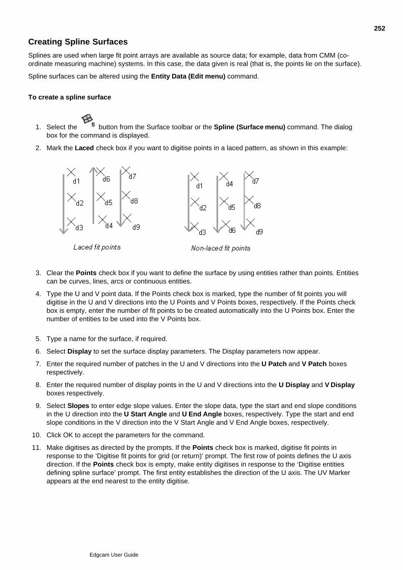
Creating Spline Surfaces
Splines are used when large fit point arrays are available as source data; for example, data from CMM (co-ordinate measuring machine) systems. In this case, the data given is real (that is, the points lie on the surface).
Spline surfaces can be altered using the Entity Data (Edit menu) command.
To create a spline surface
Select the button from the Surface toolbar or the Spline (Surface menu) command. The dialogbox for the command is displayed.
1.
Mark the Laced check box if you want to digitise points in a laced pattern, as shown in this example:2.
Clear the Points check box if you want to define the surface by using entities rather than points. Entitiescan be curves, lines, arcs or continuous entities.
3.
Type the U and V point data. If the Points check box is marked, type the number of fit points you willdigitise in the U and V directions into the U Points and V Points boxes, respectively. If the Points checkbox is empty, enter the number of fit points to be created automatically into the U Points box. Enter thenumber of entities to be used into the V Points box.
4.
Type a name for the surface, if required.5.
Select Display to set the surface display parameters. The Display parameters now appear.6.
Enter the required number of patches in the U and V directions into the U Patch and V Patch boxesrespectively.
7.
Enter the required number of display points in the U and V directions into the U Display and V Displayboxes respectively.
8.
Select Slopes to enter edge slope values. Enter the slope data, type the start and end slope conditionsin the U direction into the U Start Angle and U End Angle boxes, respectively. Type the start and endslope conditions in the V direction into the V Start Angle and V End Angle boxes, respectively.
9.
Click OK to accept the parameters for the command.10.
Make digitises as directed by the prompts. If the Points check box is marked, digitise fit points inresponse to the ‘Digitise fit points for grid (or return)’ prompt. The first row of points defines the U axisdirection. If the Points check box is empty, make entity digitises in response to the ‘Digitise entitiesdefining spline surface’ prompt. The first entity establishes the direction of the U axis. The UV Markerappears at the end nearest to the entity digitise.
11.
13.
252
Edgcam User Guide

Perform a finish.13.
A Spline passes through all fit points. Compare this example with those given for the B-Spline and Beziersurfaces: all these examples were created using the same set of fit points.
253
Edgcam User Guide
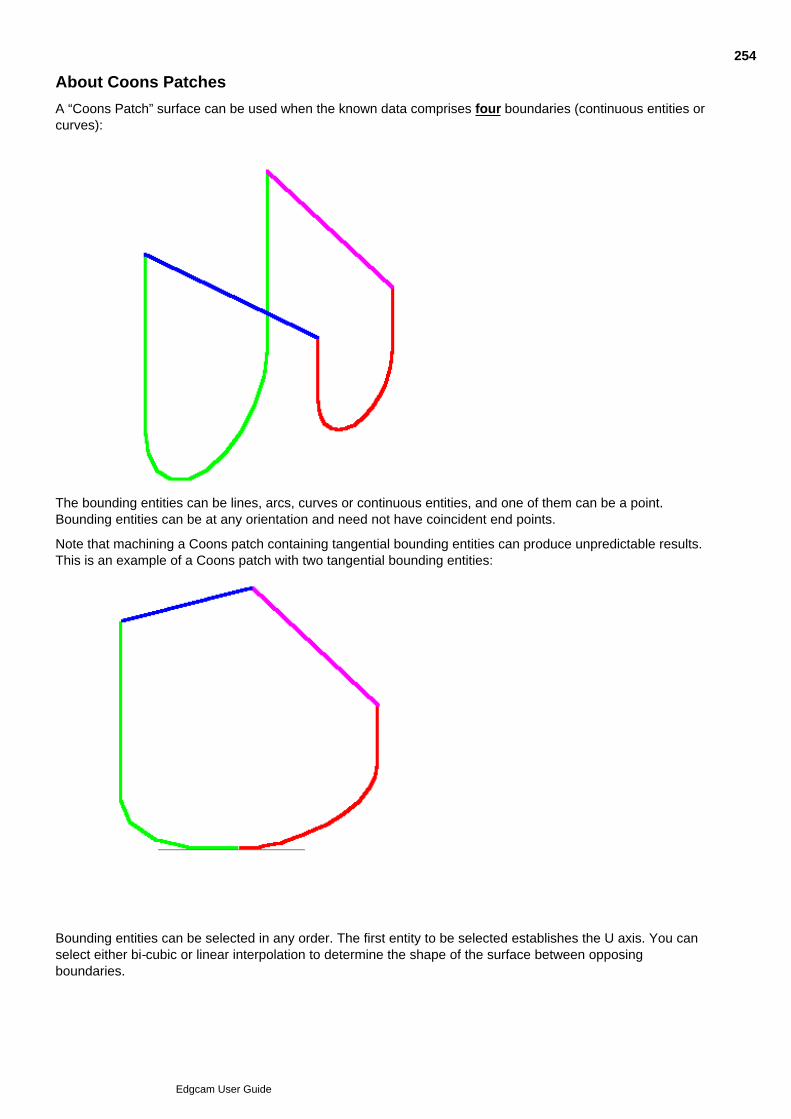
About Coons Patches
A “Coons Patch” surface can be used when the known data comprises four boundaries (continuous entities orcurves):
The bounding entities can be lines, arcs, curves or continuous entities, and one of them can be a point.Bounding entities can be at any orientation and need not have coincident end points.
Note that machining a Coons patch containing tangential bounding entities can produce unpredictable results.This is an example of a Coons patch with two tangential bounding entities:
Bounding entities can be selected in any order. The first entity to be selected establishes the U axis. You canselect either bi-cubic or linear interpolation to determine the shape of the surface between opposingboundaries.
254
Edgcam User Guide

Coons patches can also be used for aesthetic surfaces.
You can create Coons patch surfaces using the Coons Patch (Surface menu) command. The properties of aCoons Patch can be altered using the Entity Data (Edit menu) command.
To create a Coons Patch
255
Edgcam User Guide

Creating Coons Patches
Select the button from the Surface toolbar or the Coons Patch (Surface menu) command. Thedialog box for the command is displayed.
1.
Select the Linear or Bi-cubic Blend Type, as required. If Linear is selected, the display lines joining twocurves are straight. If Bi-cubic is selected the display lines are bi-cubic curves. The bi-cubic blend curvesare normal to the bounding entities.
2.
This example shows the two blend types; the Bi-cubic is on the right in all views.
Type a name for the surface if necessary.3.
Select Display to set the surface display parameters. The Display parameters now appear.4.
Enter the required number of patches in the U and V directions into the U Patch and V Patch boxesrespectively.
5.
Enter the required number of display points in the U and V directions into the U Display and V Displayboxes respectively.
6.
Click OK to accept the parameters for the command.7.
Make entity digitises to select the four bounding elements in response to the prompts.8.
Perform a finish.9.
Click here to view a typical example.
Also see
About Coons Patches
256
Edgcam User Guide

About Flowed Surfaces
The standard type of flowed surface is constructed by specifying a curve to act as an axis or ‘flow line’, alongwhich a cross section (defined by a second curve) is ‘flowed’. The cross section must lie in a plane whichpasses through one end of the flow line.
Normally, there is a 90º horizontal angle between the plane of the cross section and a tangent through the endof the axis, but Edgecam does not enforce this restriction. However, this angle remains constant as the crosssection is flowed along the axis. In addition, the cross section will not rotate about the flow line even though theflow line may twist in 3D space.
Optionally, you can specify a second cross section at the other end of the axis, which may be a different sizeand shape to the first cross section. The resulting surface is a linear blend between the two cross sections.
Flowed surfaces can be created using the Flowed (Surface menu) command. The properties of a Flowedsurface can be altered using the Entity Data (Edit menu) commands.
To create a flowed surface
257
Edgcam User Guide

Creating Flowed Surfaces
To create a flowed surface
Select the button from the Surface toolbar or the Flowed (Surface menu) command. The dialogbox for the command is displayed:
1.
Select the Blend Ends check button if you want to blend the initial cross-section into another crosssection at the other end of the flow line. The flow surface is a linear blend between the two cross-sections.
2.
Select the required Flow Type:3.
Type a name for the surface, if required.4.
Select Display to set the surface display parameters. The Display parameters now appear.5.
Enter the required number of patches in the U and V directions into the U Patch and V Patch boxesrespectively.
6.
Enter the required number of display points in the U and V directions into the U Display and V Displayboxes respectively.
7.
Click OK to accept the parameters for the command.8.
Make an entity digitise on the flow line in response to the ‘Select an entity for drive line’ prompt.9.
Make an entity digitise on the cross-section in response to the ‘Select cross section profile’ prompt. Thecross-section can be an arc, curve or continuous entity. When a continuous entity is used, all constituententities must exist on the same plane. When a curve is used, all control points must exist on the sameplane. The cross-section need not be normal to the end of the flow line.
10.
If the Blend Ends check box has been selected, make an entity digitise on the cross-section at thesecond end of the flow line in response to the ‘Select final section profile’ prompt. This cross-section isalso subject to the conditions described for the initial cross-section. When two cross-sections are used,the entity digitises which select them must both be on the same side of the flow line or a twisted surfaceis created.
11.
Perform a finish.12.
This example shows a single cross-section, in the form of a continuous entity, flowed along a curve.
258
Edgcam User Guide
Creating Surface Fillets
A surface fillet creates a smooth blend between intersecting surfaces – a primary surface, and one or moresecondary surfaces. The Fillet command creates one curve on each surface the fillet touches, following thecurve of the intersection.
When a fillet surface is created, a surface curve is generated on each of the intersecting surfaces to mark theboundary of the fillet. This then allows you to use a Trim Surface (Edit menu) command to trim each surfaceto the edge of the fillet.
The cross section at any point along the fillet’s length is an arc of either:
Constant radius
Variable radius. Click here to view a radius that decreases along the length of the fillet:
The variable radius is defined by the Start Radius and End Radius parameters. Certain limitations apply to theaccurate generation of fillets:
The surfaces must not be parallel or nearly parallel at any point along the fillet.
The fillet cannot take place around a tight corner, the radius of which is less than the fillet radius.
A fillet surface can be intersected, trimmed and filleted in the same way as any other surface type.
You can create a fillet surface using the Fillet (Surface menu) command.
The properties of a Surface Fillet can be altered using the Entity Data (Edit menu) command.
To create a surface fillet
259
Edgcam User Guide

Creating Surface Fillets
To create a surface fillet
Select the button from the Surface toolbar or the Fillet (Surface menu) command. 1.
Check the End Points box if you want to digitise the start and end points of the fillet. An end may be freedigitised or it may be trimmed to a specific plane.
2.
Check the Trim Surfaces box if you want to trim the selected surfaces back to the fillet edge.3.
Enter the start and end radii of the surface fillet in the Start Radius and End Radius boxes respectively.Variable radius fillets can be produced by entering different values in these fields. Edgecam interpolatesbetween the two end radii.
4.
Alter the default interpolation Tolerance for the calculation of the fillet, if required. The higher thetolerance the more accurate, but also more lengthy, the calculations.
5.
Amend the default Search Grid Density, if required. This is the density of the search grid used whensearching for the intersection. In most cases a density of 2 x 2 will suffice (Search Grid Density = 2).However, for surfaces which overlap in a number of places, or only overlap by a small amount, a highersearch density may be required to find all possible solutions. The higher the density, the longer thecommand's calculations will take.
6.
Enter a name for the fillet, if required.7.
Select Display to set the surface display parameters.8.
Enter the required number of patches in the U and V directions into the U Patch and V Patch boxesrespectively.
9.
Enter the required number of display points in the U and V directions into the U Display and V Displayboxes respectively.
10.
Click OK to accept the parameters for the command.11.
Enter a digitise in response to the 'Digitise primary surface' prompt.12.
An arrow shows the side of the surface which will be used to generate the fillet. If there is more than onepossible side, you will be prompted to select it (see example).
Enter a digitise in response to the ‘Digitise secondary surface(s)’ prompt.13.
If you selected the End Points check box, enter a digitise in response to the ‘Digitise entity/position todefine start of fillet’ prompt. Enter a digitise in response to the ‘Digitise entity/position to define end offillet’ prompt.
14.
Perform a finish.15.
This example shows two fillets produced on a part:
260
Edgcam User Guide

About Offset Surfaces
An Offset surface is a distinct surface type which is generated from an existing surface. The offset surface maybe based on a tool or geometric offset, or both types of offset together. Use the Offset (Surface menu)command.
Geometric Offset Surface
A geometric offset surface is constructed by offsetting each point on the original surface by a defined constantamount, normal to the original surface. Geometric offset surfaces can be intersected, trimmed, filleted, offsetand machined in the same manner as any other primitive surface.
Tool Offset Surface
A tool offset surface is dependent on the geometry of the currently selected tool and is defined as the locus thatthe set point of the tool makes when cutting the underlying surface.
Tool offset surfaces may be created for any ISO-defined tool and prevent gouging. Usually, two or more offsetsurfaces are generated and then trimmed before you would generate a toolpath.When machining an offset surface, any sharp corners may cause inaccurate results. There are two solutions:
Create two single surfaces and offset/machine them separately
Use a fillet surface if the sharp corner is not required.
To create an offset surface
261
Edgcam User Guide

Creating Offset Surfaces
To create an offset surface
Select the button from the Surface toolbar or the Offset (Surface menu) command. The Offsetdialog box is displayed.
1.
Complete the parameters as required.2.
Select Tool to set the Tool parameters. The Tool parameters are displayed.3.
Complete the parameters. (These depend on the selected tool type.)4.
Select Display to set the surface display parameters. The Display parameters now appear.5.
Enter the required number of patches in the U and V directions into the U Patch and V Patch boxesrespectively.
6.
Enter the required number of display points in the U and V directions into the U Display and V Displayboxes respectively.
7.
Click OK to accept the command parameters.8.
Enter a digitise in reply to the ‘Select surface to offset’ prompt. If you selected the Select Side checkbox, Edgecam displays an arrow indicating the side on which the offset will be applied.
9.
If required, make a digitise on the other side of the entity to move the arrow.10.
Perform a finish.11.
The offset surface is produced.
262
Edgcam User Guide

Creating Aesthetic Surface Types
The following Surface menu commands are usually used to produce surfaces for which the aesthetic qualityand smoothness of the surface has overriding priority.
B-Spline
Bezier
Coons Patch
(The Coons Patch is also used for functional surfaces, and described under Creating Functional SurfaceTypes.)
263
Edgcam User Guide
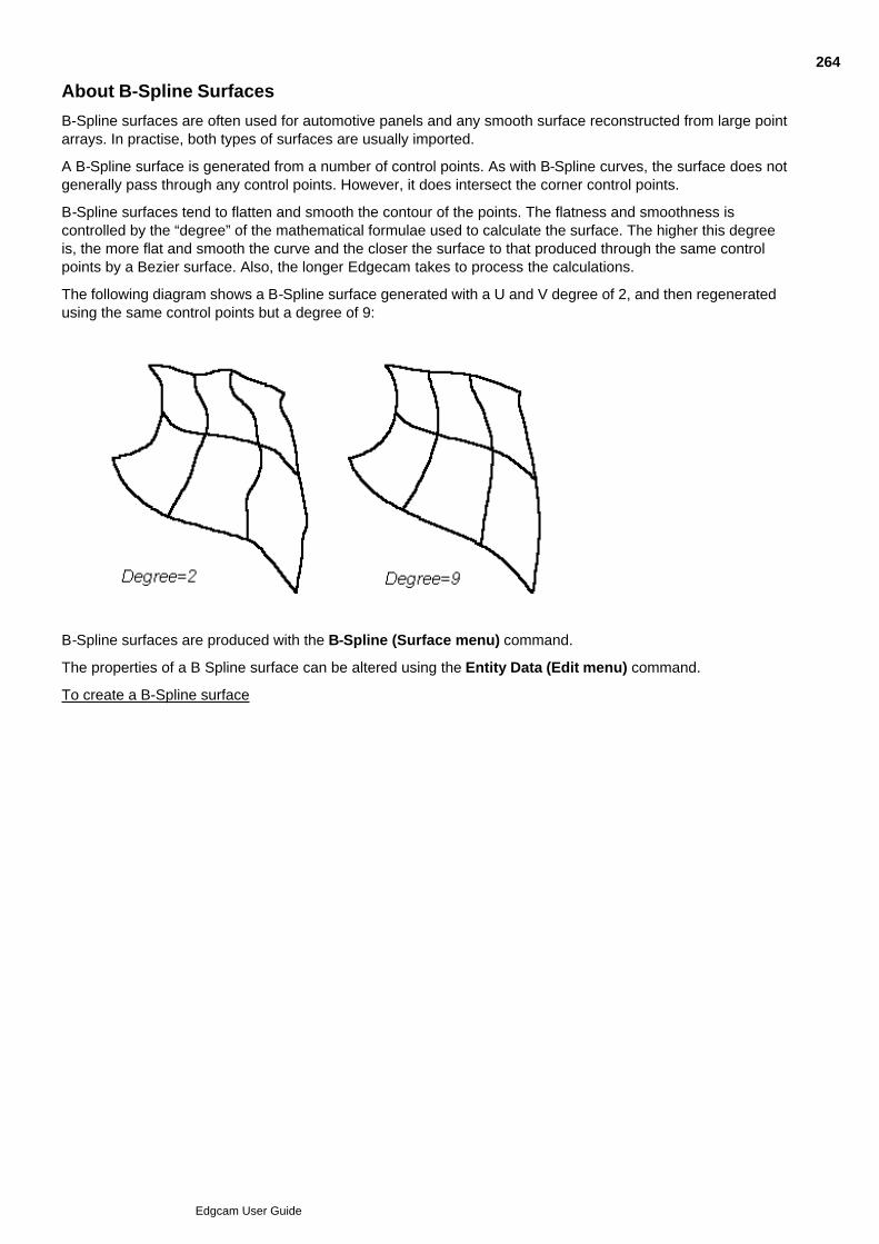
About B-Spline Surfaces
B-Spline surfaces are often used for automotive panels and any smooth surface reconstructed from large pointarrays. In practise, both types of surfaces are usually imported.
A B-Spline surface is generated from a number of control points. As with B-Spline curves, the surface does notgenerally pass through any control points. However, it does intersect the corner control points.
B-Spline surfaces tend to flatten and smooth the contour of the points. The flatness and smoothness iscontrolled by the “degree” of the mathematical formulae used to calculate the surface. The higher this degreeis, the more flat and smooth the curve and the closer the surface to that produced through the same controlpoints by a Bezier surface. Also, the longer Edgecam takes to process the calculations.
The following diagram shows a B-Spline surface generated with a U and V degree of 2, and then regeneratedusing the same control points but a degree of 9:
B-Spline surfaces are produced with the B-Spline (Surface menu) command.
The properties of a B Spline surface can be altered using the Entity Data (Edit menu) command.
To create a B-Spline surface
264
Edgcam User Guide

Creating B-Spline Surfaces
To create a B Spline
Select the button from the Surface toolbar or the B Spline (Surface menu) command. The dialogbox for the command is displayed.
1.
Select the Laced check box if you want to digitise points in a laced pattern. See Creating Spline Surfacesfor a diagram.
2.
Type the degree of curvature in the U and V directions into the U Degree and V Degree boxes,respectively.
3.
Type the number of digitised control points in the U and V directions into the U Points and V Pointsboxes, respectively.
4.
Type a Name for the surface, if required.5.
Select Display to set the surface display parameters. The Display parameters now appear.6.
Enter the required number of patches in the U and V directions into the U Patch and V Patch boxesrespectively.
7.
Enter the required number of display points in the U and V directions into the U Display and V Displayboxes respectively.
8.
Click OK to accept the command parameters.9.
Digitise control points in response to the ‘Digitise control grid points (or return)’ prompt. The first row ofpoints defines the U axis direction.
10.
Perform a finish.11.
Compare this example of a B Spline surface with those given for the Bezier and Spline surfaces: all theseexamples were created using the same set of points.
265
Edgcam User Guide

About Bezier Surfaces
Bezier surfaces are:
used for any smooth surface constructed from a small array of control points, where the input of thedesigner overrides any need for a precisely defined surface; for example, in automobile panel design.
produced with the Bezier (Surface menu) command, interpolating between control points to affect thetotal surface contour.
a subset of the more general B-Spline surface.
a simple way of creating a smooth fillet in a profile, or as a ‘best fit’ approximation between control pointsif you are not interested in following the points too closely (except at the end points).
In Edgecam, the Bezier curve is faster to compute than a B Spline. Unlike B-Splines however, if you alter theposition of one control point in a Bezier surface, the entire surface is recalculated.
The properties of a Bezier surface can be altered using the Entity Data (Edit menu) command.
To create a Bezier surface
266
Edgcam User Guide

Creating Bezier Surfaces
To create a Bezier surface
Select the button from the Surface toolbar or the Bezier (Surface menu) command. The dialogbox for the command is displayed.
1.
Select the Laced check box if you want to digitise points in a laced pattern, as described under CreatingSpline Surfaces.
2.
Type the number of control points you will digitise in the U and V directions into the U Points and VPoints boxes, respectively.
3.
Type a name for the surface, if required.4.
Select Display to set the surface display parameters. The Display parameters now appear.5.
Enter the required number of patches in the U and V directions into the U Patch and V Patch boxesrespectively.
6.
Enter the required number of display points in the U and V directions into the U Display and V Displayboxes respectively.
7.
Click OK to accept the parameters for the command.8.
Digitise control points in response to the ‘Digitise control grid points (or return)’ prompt. The first row ofpoints defines the U axis direction.
9.
Perform a finish.10.
Compare this example of a Bezier surface with those given for the B Spline and Spline surfaces: all theseexamples were created using the same set of points.
267
Edgcam User Guide

Creating More Surface Types
In the Surfaces menu there are these commands:
Grid of Points Lofted Curves
Primitives Slab Primitives Sphere
Primitives Cylinder Primitives Cone
Please note that these commands are PDI add-in options and do not support Intellisnap picking. To selectentities you can use either of the following methods:
Select the Entity icon from the Input toolbar
Hold down the right-hand mouse button and select the Entity command from the Shortcut menu
Hold down the Ctrl key
268
Edgcam User Guide
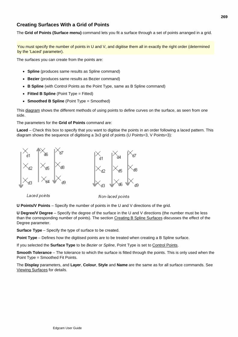
Creating Surfaces With a Grid of Points
The Grid of Points (Surface menu) command lets you fit a surface through a set of points arranged in a grid.
You must specify the number of points in U and V, and digitise them all in exactly the right order (determinedby the 'Laced' parameter).
The surfaces you can create from the points are:
Spline (produces same results as Spline command)
Bezier (produces same results as Bezier command)
B Spline (with Control Points as the Point Type, same as B Spline command)
Fitted B Spline (Point Type = Fitted)
Smoothed B Spline (Point Type = Smoothed)
This diagram shows the different methods of using points to define curves on the surface, as seen from oneside.
The parameters for the Grid of Points command are:
Laced – Check this box to specify that you want to digitise the points in an order following a laced pattern. Thisdiagram shows the sequence of digitising a 3x3 grid of points (U Points=3, V Points=3):
U Points/V Points – Specify the number of points in the U and V directions of the grid.
U Degree/V Degree – Specify the degree of the surface in the U and V directions (the number must be lessthan the corresponding number of points). The section Creating B Spline Surfaces discusses the effect of theDegree parameter.
Surface Type – Specify the type of surface to be created.
Point Type – Defines how the digitised points are to be treated when creating a B Spline surface.
If you selected the Surface Type to be Bezier or Spline, Point Type is set to Control Points.
Smooth Tolerance – The tolerance to which the surface is fitted through the points. This is only used when thePoint Type = Smoothed Fit Points.
The Display parameters, and Layer, Colour, Style and Name are the same as for all surface commands. SeeViewing Surfaces for details.
269
Edgcam User Guide
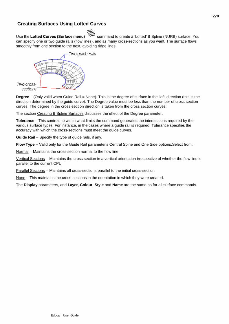
Creating Surfaces Using Lofted Curves
Use the Lofted Curves (Surface menu) command to create a 'Lofted' B Spline (NURB) surface. Youcan specify one or two guide rails (flow lines), and as many cross-sections as you want. The surface flowssmoothly from one section to the next, avoiding ridge lines.
Degree – (Only valid when Guide Rail = None). This is the degree of surface in the 'loft' direction (this is thedirection determined by the guide curve). The Degree value must be less than the number of cross sectioncurves. The degree in the cross-section direction is taken from the cross section curves.
The section Creating B Spline Surfaces discusses the effect of the Degree parameter.
Tolerance – This controls to within what limits the command generates the intersections required by thevarious surface types. For instance, in the cases where a guide rail is required, Tolerance specifies theaccuracy with which the cross-sections must meet the guide curves.
Guide Rail – Specify the type of guide rails, if any.
Flow Type – Valid only for the Guide Rail parameter's Central Spine and One Side options.Select from:
Normal – Maintains the cross-section normal to the flow line
Vertical Sections – Maintains the cross-section in a vertical orientation irrespective of whether the flow line isparallel to the current CPL
Parallel Sections – Maintains all cross-sections parallel to the initial cross-section
None – This maintains the cross-sections in the orientation in which they were created.
The Display parameters, and Layer, Colour, Style and Name are the same as for all surface commands.
270
Edgcam User Guide
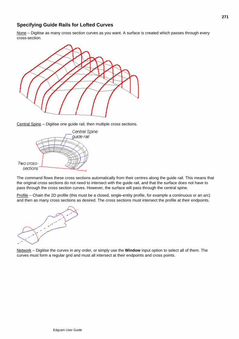
Specifying Guide Rails for Lofted Curves
None – Digitise as many cross section curves as you want. A surface is created which passes through everycross-section.
Central Spine – Digitise one guide rail, then multiple cross sections.
The command flows these cross sections automatically from their centres along the guide rail. This means thatthe original cross sections do not need to intersect with the guide rail, and that the surface does not have topass through the cross section curves. However, the surface will pass through the central spine.
Profile – Chain the 2D profile (this must be a closed, single-entity profile, for example a continuous or an arc)and then as many cross sections as desired. The cross sections must intersect the profile at their endpoints.
Network – Digitise the curves in any order, or simply use the Window input option to select all of them. Thecurves must form a regular grid and must all intersect at their endpoints and cross points.
271
Edgcam User Guide
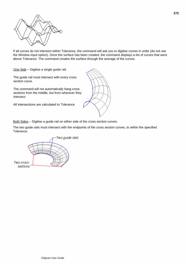
If all curves do not intersect within Tolerance, the command will ask you to digitise curves in order (do not usethe Window input option). Once the surface has been created, the command displays a list of curves that wereabove Tolerance. The command creates the surface through the average of the curves.
One Side – Digitise a single guide rail.
The guide rail must intersect with every crosssection curve.
The command will not automatically hang crosssections from the middle, but from wherever theyintersect.
All intersections are calculated to Tolerance.
Both Sides – Digitise a guide rail on either side of the cross section curves.
The two guide rails must intersect with the endpoints of the cross section curves, to within the specifiedTolerance.
272
Edgcam User Guide

Creating Primitive Surfaces
There are four commands in the Surface menu for creating simple solid shapes using surfaces:
Primitives, Slab Primitives, Sphere
Primitives, Cylinder Primitives, Cone
These surfaces can be created dynamically by setting one or more of the parameters controlling the shape'sdimensions to <Digitise>.
However, to be able to digitise the third dimension of the shape you will need to have at least one extra viewport active.
Please note that these commands are PDI add-in options and do not support Intellisnap picking. To selectentities you can use either of the following methods:
Select the Entity icon from the Input toolbar
Hold down the right-hand mouse button and select the Entity command from the Shortcut menu
Hold down the Ctrl key
273
Edgcam User Guide

Working with Surface Curves
Surface curves can be generated by Edgecam for intersecting surfaces. In fact, two curves are generated foreach intersection, one for each surface.
The Surface menu commands that produce surface curves are:
Generate, Boundaries
Generate, Cross Sections
Generate, Intersection
Generate, Split Line
Generate, Bridge Surface
Project
The smoothness of the surface curves depends on the value used in the tolerance parameter for thesecommands.
See Also
Controlling the Search Grid Density
274
Edgcam User Guide
Generating Surface Boundaries
You may want to create surface curves around the boundary of a surface. This could be:
To create a surface between surfaces. Depending on the surface type, a surface may not have aselectable edge (for example, Spline, B-Spline and Bezier surfaces do not have edges, but ruledsurfaces have two).
To drive a tool along a surface curve on the edge of a surface (in Five Axis machining).
To generate a surface boundary
Select the Generate, Boundaries (Surface menu) command.1.
Select the required options on the dialog.2.
Digitise one or more surfaces.3.
Perform a finish.4.
Separate surface curves are created for each edge of the selected surface.
The dialog box for the command offers the following parameters:
Generate – Specify the type of boundary that will be created for the selected surface(s). Choose between:
Generate Surface Curves – Checking this option allows you to select surfaces only to generate surface curvesaround the boundaries of the selected surface(s). Note that the surface cannot be deleted because the surfacecurves are dependent on it.
Generate Base Entities – Checking this option allows you to select surfaces or surface curves to beconverted to lines, arcs, Splines or B-Splines.
Generate 2D entities – Checking this option allows you to select surfaces, surface curves, Splines or B-Splines to be converted to 2D curves at the current CPL level.
Tidy Base Entities – Check this box to replace a set of co-linear lines with a single line, and replace sequentialarcs of the same radius that also lie in the same plane with a single arc.
Outer Edges – (2D entities only) Check this box to join outer edges of the selected surfaces to form a union.The resulting geometry will be created as lines at the current Z level and can be used as containmentboundaries for subsequent machining cycles.
Note that surfaces without fully enclosing boundary curves such as spheres or cylinders may not be taken intoaccount. Also note that a surface that doubles back will not return a boundary that represents the furthestextent of the surface.
3D Curves
Curves – The boundary curves can be generated as either Splines or B-Splines.
Control Points – Specify the number of control points for the curves (default 40).
275
Edgcam User Guide

Generating Cross Sections
This command creates one or more cross sections thorough a surface. The cross sections start at the specifiedlevel and the depth is incremented by the value entered until the number of cuts you asked for have beengenerated. The generated cross sections are surface curves.
Note that cross sections can only be generated in the current CPL and for surfaces that are displayed.
Select the Generate, Cross Sections (Surface menu) command. The Cross Sections dialog box isdisplayed.
1.
Enter the Initial Level (the height of the first cross section).2.
Set the Increment; that is the distance between subsequent cross sections.3.
Enter the number of cross sections you require (Number of Cuts).4.
If necessary, update the Tolerance; that is, the maximum distance allowable between the midpoint of anysurface curve segment and the exact cross sectional curve.
5.
If necessary, update the Search Grid Density.6.
The Search Grid Density controls the density of the search for the intersection. In most cases a density of 2 x 2will work (Search Grid Density = 2). However, for surfaces which overlap in a number of places, or only overlapby a small amount, a higher search density may be required to find all possible solutions. The higher theSearch Grid Density, the longer Edgecam takes to find the solutions.
Click OK to accept the parameters for the command.7.
Digitise a point on each surface to be cross sectioned.8.
Perform a finish.9.
The cross sections are now displayed.
276
Edgcam User Guide
Generating Surface Intersections
Curves can be generated by Edgecam for intersecting surfaces. In fact, two curves are generated for eachintersection, one for each surface. The smoothness of these curves depends on the selected tolerance. To generate an intersection
Select the button from the Surface toolbar or the Generate, Intersection (Surface menu)command. The dialog box for the command is displayed:
1.
Enter the Tolerance for the calculations.2.
Enter a new Search Grid Density, if required.3.
The Search Grid Density controls the density of the search for the intersection. In most cases a density of 2 x 2will work (Search Grid Density = 2). However, for surfaces which overlap in a number of places, or only overlapby a small amount, a higher search density may be required to find all possible solutions. The higher theSearch Grid Density, the longer Edgecam takes to find the solutions.
Click OK to accept the parameters for the command.4.
Enter a digitise in response to the ‘Digitise primary surface’ prompt.5.
Enter one or more digitises in response to the ‘Digitise secondary surface(s)’ prompt.6.
Note that if the order of the surface selection is changed, the curves may be slightly different. However, theywill be within the selected tolerance of the true solution.
Example
277
Edgcam User Guide

Generating Split Lines
The Generate, Split Line (Surface menu) command is particularly useful for more complicated mould shapes.
The surface curve is generated by finding all the points on the selected surface where a line normal to thesurface lies at a given angle to the plane of the current CPL.
To generate a split line
Select the Generate, Split Line (Surface menu) command. The Split Line dialog box is displayed.1.
Enter the Angle that the surface curve normal is to make with the current CPL.2.
If necessary, update the Tolerance; that is, the maximum allowable distance between the mid point ofany segment of the split line surface curve being generated and the ‘mathematically correct’ surfacecurve.
3.
If necessary, update the Search Grid Density.4.
Click OK to accept the parameters for the command.5.
Digitise each surface for which you want to find a split line.6.
Perform a finish.7.
The split line is now generated.
278
Edgcam User Guide
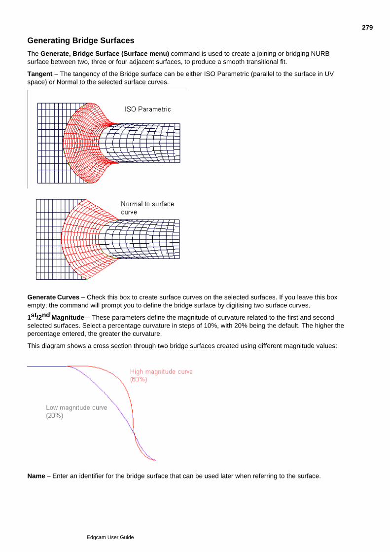
Generating Bridge Surfaces
The Generate, Bridge Surface (Surface menu) command is used to create a joining or bridging NURBsurface between two, three or four adjacent surfaces, to produce a smooth transitional fit.
Tangent – The tangency of the Bridge surface can be either ISO Parametric (parallel to the surface in UVspace) or Normal to the selected surface curves.
Generate Curves – Check this box to create surface curves on the selected surfaces. If you leave this boxempty, the command will prompt you to define the bridge surface by digitising two surface curves.
1st/2nd Magnitude – These parameters define the magnitude of curvature related to the first and secondselected surfaces. Select a percentage curvature in steps of 10%, with 20% being the default. The higher thepercentage entered, the greater the curvature.
This diagram shows a cross section through two bridge surfaces created using different magnitude values:
Name – Enter an identifier for the bridge surface that can be used later when referring to the surface.
279
Edgcam User Guide

The Display tab contains the standard UV patch and point modifiers used by all surfaces, which define how thebridge surface is to be shown on the screen.
280
Edgcam User Guide
Projecting Entities onto Surfaces
The Project (Surface menu) command is used to project one or more points, lines, arcs, curves or continuousentities in the current CPL onto one or more surfaces creating one or more surface curves.
Note that any arcs or curves that are projected consist of vectors, so that the arc/curve should be generated tothe desired display tolerance before being projected. To project entities onto one or more surfaces
Select the button from the Surface toolbar or the Project (Surface menu) command. The dialogbox for the command is displayed.
1.
Enter the tolerance; that is, the maximum distance that the midpoint of a segment of the surface curvemay be from the true curve of projection. The default is 0.01.
2.
Click OK to accept the parameters and dismiss the dialog box.3.
Digitise the surface(s) to project onto.4.
Perform a finish.5.
Digitise one or more entities to be projected.6.
Perform a finish.7.
Note that unpredictable results will occur if this command is used with a surface which, for some XY co-ordinates, has two or more Z values; for example, a folded surface with an overhang.
For trimmed surfaces, unpredictable results will also occur if the underlying (untrimmed) surface folds overeven if the trimmed one does not.
This example shows an arc entity projected onto a surface with two Z values at the same XY co-ordinate.
281
Edgcam User Guide

Controlling the Search Grid Density
Commands such as Generate Intersection (Surface menu) and Fillet (Surface menu) use a parametercalled Search Grid Density to control how the system detects intersecting surfaces. This is an integer, usuallydefaulting to 2.
If the system does not detect the intersection, you could redo the command with a higher search grid value. Tosave you time, the Surfaces tab or button on the Preferences (Options menu) command provides aparameter called Auto Grid Double. This parameter lets you set the number of times you want the search gridto double in density and search again for an intersection.
For example, with an Auto Grid Double value of 2, the system would perform a search for an intersection, and ifone was not found, automatically double the density of the search grid and try again. If an intersection was stillnot found, the system would again double the density of the grid and perform a final search.
You should not use a value higher than 4 unless you are using a powerful computer.
282
Edgcam User Guide

Altering Existing Surfaces
Although you can change the layer, colour, style and name of an entity or entities with the Entity Data (Editmenu) commands, there are commands for changing surfaces or the entities used to create surfaces:
Generate, Control Points (Surface menu)
Extend (Surface menu)
Trim Surface (Edit menu)
Surface Curve (Edit menu)
Joined (Surface menu)
Surface Group (Surface menu)
Generate, Blend Corner (Surface menu)
See Also
Editing Surfaces Created with Fit Points
283
Edgcam User Guide

Editing Surfaces Created With Fit Points
When editing a surface that was created using fit points, rather than control points you may achieve anunexpected result.
Note that:
Fit points ensure that the surfaces go through the points you specify.
Control points control the shape of the entity, depending on the mathematical equation used to createthe entity.
When you use fit points to create a surface, Edgecam calculates the control points from the digitised fit pointsand the degree parameter. The fit point information is discarded.
Subsequently, if you edit the surface it is treated as though it was created using control points. If you changethe surface's Degree parameter the entity may not necessarily go through the original fit points.
284
Edgcam User Guide

Generating Control Points for Surfaces
The Generate, Control Points (Surface menu) command recreates the control points originally used toproduce a B-Spline, Bezier or Spline surface. The control points can then be used to generate another surface. To regenerate the control points for a B Spline, Bezier or Spline surface
Select the Generate, Control Points (Surface menu) command.1.
Entity digitise one or more surfaces.2.
Perform a finish.3.
Point entities are created at the location of each control point for the selected surfaces.
285
Edgcam User Guide

Extending Surfaces
You may want to extend a surface along one or more of its edges, for example if you do not have enough datato specify a complete surface. Note that extending is not permitted on a surface group, since the relevantboundary of each surface must be specified.
Each extended portion is extended at a tangent to the original surface.
When a surface has been extended, its U and V parameters are adjusted so that U and V co-ordinates on thenew surface still range from 0 to 1. If you use the Entity (Verify menu) command to show the parameters forthe surface, the U and V parameters are given in terms of the original surface.
In this example an extension factor of 1 has been used (giving 100% extension):
The U parameter range reported by Entity (Verify menu) command would be 0 to 2, rather than 0 to 1 as it isbased on the original dimensions of the surface.
To extend a non-offset surface
286
Edgcam User Guide
Trimming Surface Curves
Sometimes it is not possible to trim a surface as the surface curve intersects itself or contains a gap. TheSurface Curve (Edit menu) command allows you to edit the surface curve to produce a more useful curve. To trim surface curves
Select the Surface Curve (Edit menu) command. The parameters for the command are displayed.1.
First – Check this box to trim the first surface curve that you digitise. You keep the end of the curvethat you digitise.
Second – Check this box to trim the second surface curve that you digitise. You keep the end of thecurve that you digitise.
Break – Check this box to remove the line vector at the digitised point on the surface curve, creating abreak.
Join – Check this box to join the digitised surface curves, providing that the end points are not furtherapart than the current system tolerance. This tolerance is set using the System Tolerance parameter inthe Preferences (Options menu) command.
Click OK.2.
Digitise the surface curves according to the parameter selections you made.3.
Perform a finish.4.
The surface curves are now trimmed.
287
Edgcam User Guide

Trimming Surfaces
A trimmed surface is a surface with a piece removed along a surface curve.
You can use the Trim Surface (Edit menu) command to do this.
Note that trimming is not permitted on a surface group, since it would be necessary to specify which part ofeach surface member would be retained and which would be removed.
Trimming is a convenient way of constraining a toolpath in order to prevent the gouging of adjacent surfaces.
A trimmed surface can be exploded as any other surface.
Sometimes a sequence of intersection operations produces a set of surface curves which intersect or havegaps between their ends. In order to produce a boundary which the Trim Surface command will understand, thecurves must be trimmed against each other.
The portion of the curve retained during a trim operation is the one closest to the digitised point. When theintersection point is beyond the end of a curve, the last vector on the curve is extended to that point.
To trim a surface
288
Edgcam User Guide
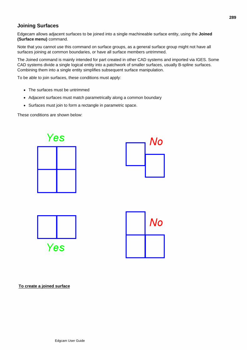
Joining Surfaces
Edgecam allows adjacent surfaces to be joined into a single machineable surface entity, using the Joined(Surface menu) command.
Note that you cannot use this command on surface groups, as a general surface group might not have allsurfaces joining at common boundaries, or have all surface members untrimmed.
The Joined command is mainly intended for part created in other CAD systems and imported via IGES. SomeCAD systems divide a single logical entity into a patchwork of smaller surfaces, usually B-spline surfaces.Combining them into a single entity simplifies subsequent surface manipulation.
To be able to join surfaces, these conditions must apply:
The surfaces must be untrimmed
Adjacent surfaces must match parametrically along a common boundary
Surfaces must join to form a rectangle in parametric space.
These conditions are shown below:
To create a joined surface
289
Edgcam User Guide
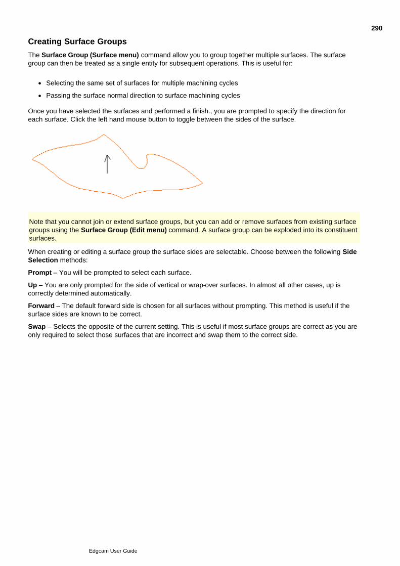
Creating Surface Groups
The Surface Group (Surface menu) command allow you to group together multiple surfaces. The surfacegroup can then be treated as a single entity for subsequent operations. This is useful for:
Selecting the same set of surfaces for multiple machining cycles
Passing the surface normal direction to surface machining cycles
Once you have selected the surfaces and performed a finish., you are prompted to specify the direction foreach surface. Click the left hand mouse button to toggle between the sides of the surface.
Note that you cannot join or extend surface groups, but you can add or remove surfaces from existing surfacegroups using the Surface Group (Edit menu) command. A surface group can be exploded into its constituentsurfaces.
When creating or editing a surface group the surface sides are selectable. Choose between the following SideSelection methods:
Prompt – You will be prompted to select each surface.
Up – You are only prompted for the side of vertical or wrap-over surfaces. In almost all other cases, up iscorrectly determined automatically.
Forward – The default forward side is chosen for all surfaces without prompting. This method is useful if thesurface sides are known to be correct.
Swap – Selects the opposite of the current setting. This is useful if most surface groups are correct as you areonly required to select those surfaces that are incorrect and swap them to the correct side.
290
Edgcam User Guide
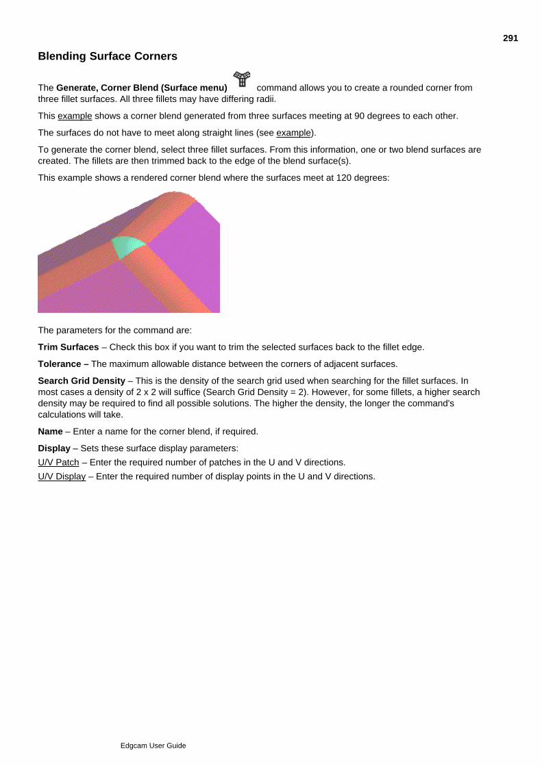
Blending Surface Corners
The Generate, Corner Blend (Surface menu) command allows you to create a rounded corner fromthree fillet surfaces. All three fillets may have differing radii.
This example shows a corner blend generated from three surfaces meeting at 90 degrees to each other.
The surfaces do not have to meet along straight lines (see example).
To generate the corner blend, select three fillet surfaces. From this information, one or two blend surfaces arecreated. The fillets are then trimmed back to the edge of the blend surface(s).
This example shows a rendered corner blend where the surfaces meet at 120 degrees:
The parameters for the command are:
Trim Surfaces – Check this box if you want to trim the selected surfaces back to the fillet edge.
Tolerance – The maximum allowable distance between the corners of adjacent surfaces.
Search Grid Density – This is the density of the search grid used when searching for the fillet surfaces. Inmost cases a density of 2 x 2 will suffice (Search Grid Density = 2). However, for some fillets, a higher searchdensity may be required to find all possible solutions. The higher the density, the longer the command'scalculations will take.
Name – Enter a name for the corner blend, if required.
Display – Sets these surface display parameters:
U/V Patch – Enter the required number of patches in the U and V directions.
U/V Display – Enter the required number of display points in the U and V directions.
291
Edgcam User Guide

Checking the Validity of a Surface
It is possible to create or import invalid surfaces that can later cause problems when applying machiningcycles. To validate your surfaces, display the surface normals by using the Surface Normals (Verify menu)command. Generally, the normals should display a fairly regular pattern with no abrupt change in vector.
292
Edgcam User Guide

Problem Areas
Degenerate surfaces (surfaces that cross over themselves)
Degenerate surface curves on trimmed surfaces (surface curve intersects with itself)
Tangent continuous corners on Coons Patches
293
Edgcam User Guide
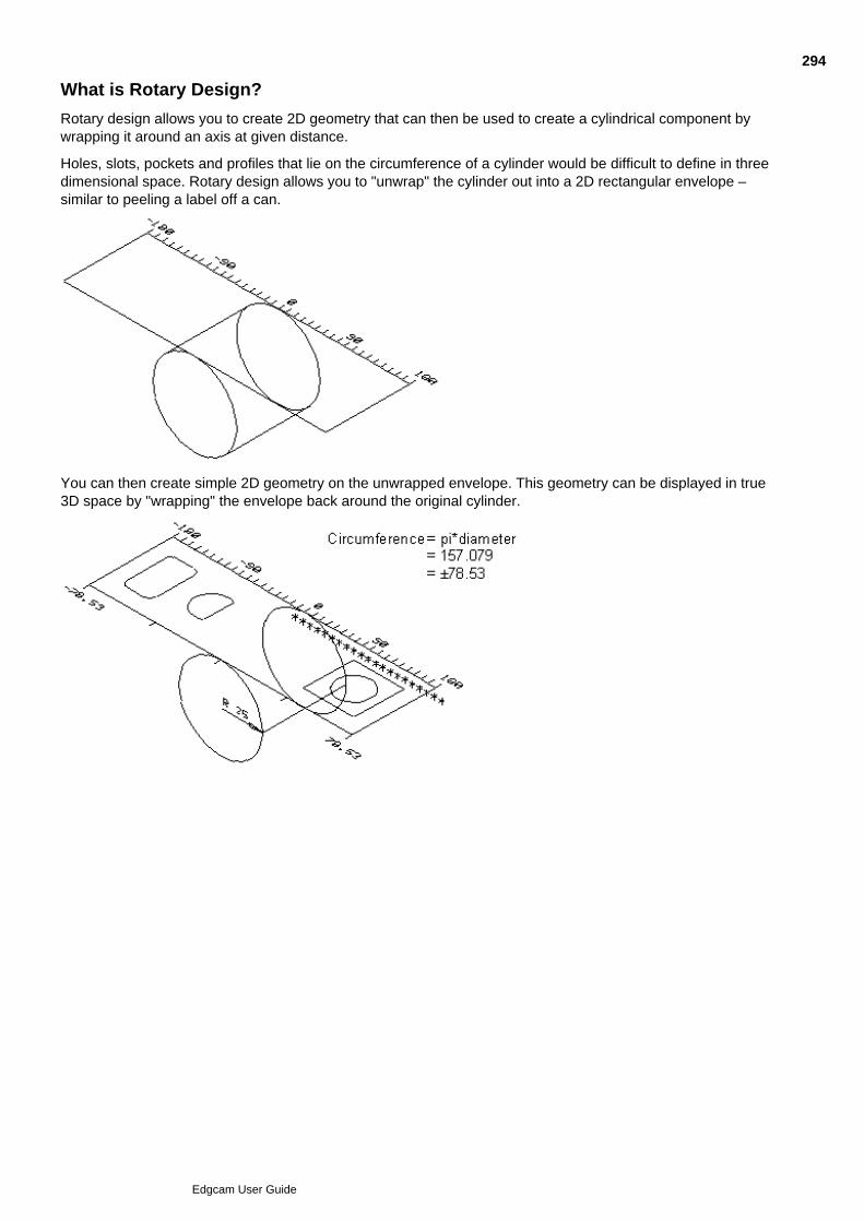
What is Rotary Design?
Rotary design allows you to create 2D geometry that can then be used to create a cylindrical component bywrapping it around an axis at given distance.
Holes, slots, pockets and profiles that lie on the circumference of a cylinder would be difficult to define in threedimensional space. Rotary design allows you to "unwrap" the cylinder out into a 2D rectangular envelope –similar to peeling a label off a can.
You can then create simple 2D geometry on the unwrapped envelope. This geometry can be displayed in true3D space by "wrapping" the envelope back around the original cylinder.
294
Edgcam User Guide
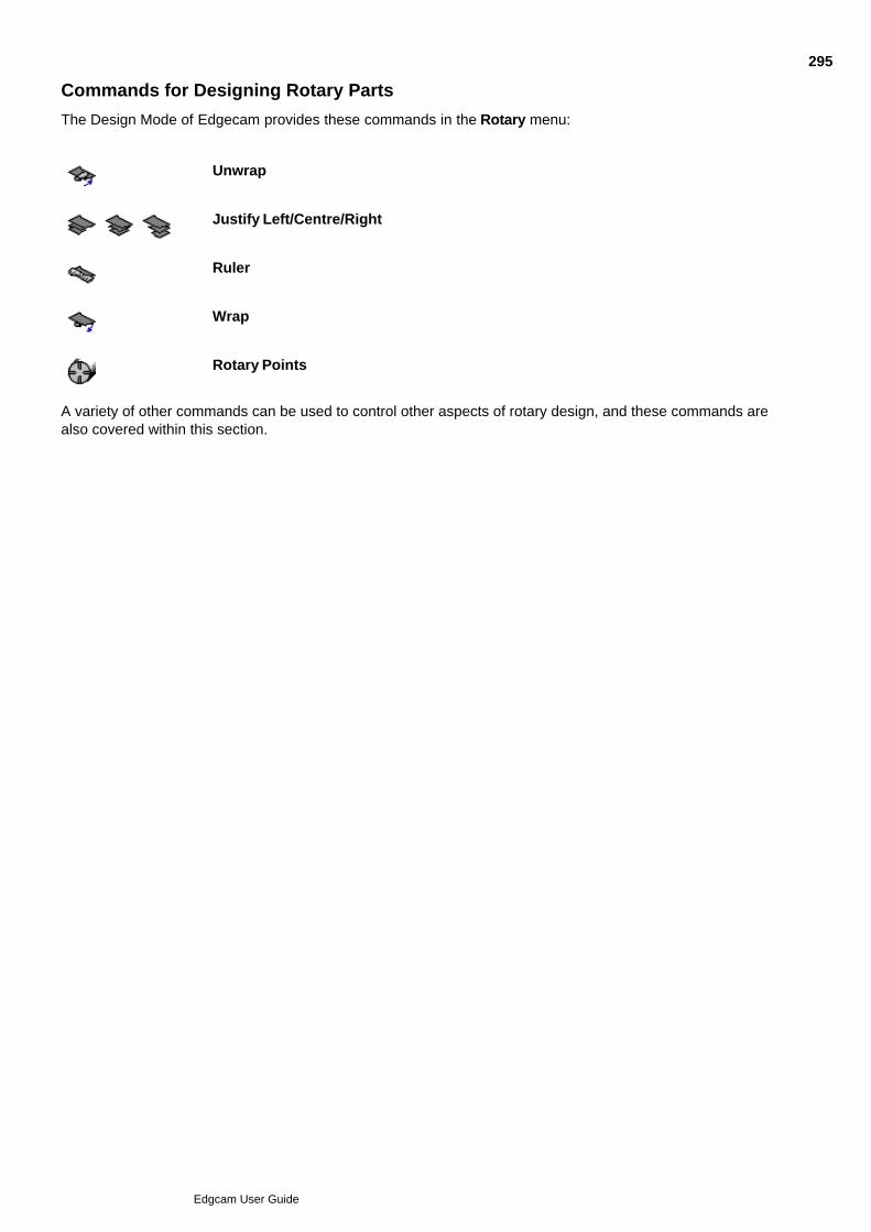
Commands for Designing Rotary Parts
The Design Mode of Edgecam provides these commands in the Rotary menu:
Unwrap
Justify Left/Centre/Right
Ruler
Wrap
Rotary Points
A variety of other commands can be used to control other aspects of rotary design, and these commands arealso covered within this section.
295
Edgcam User Guide
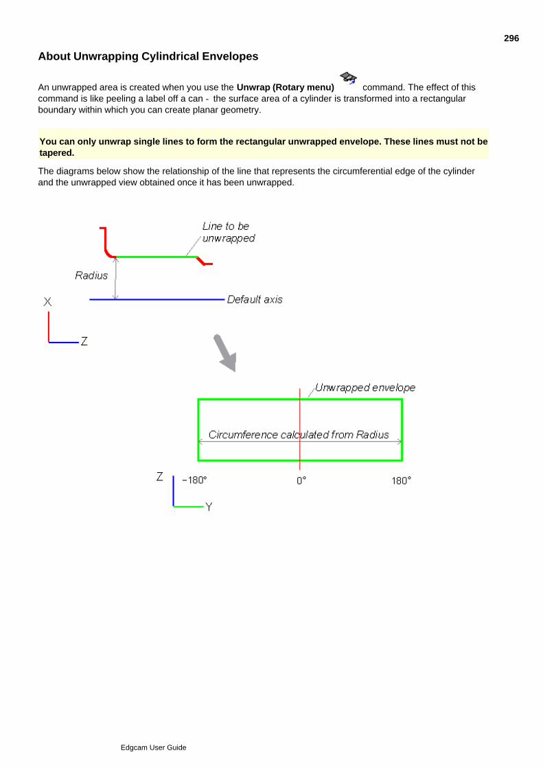
About Unwrapping Cylindrical Envelopes
An unwrapped area is created when you use the Unwrap (Rotary menu) command. The effect of thiscommand is like peeling a label off a can - the surface area of a cylinder is transformed into a rectangularboundary within which you can create planar geometry.
You can only unwrap single lines to form the rectangular unwrapped envelope. These lines must not betapered.
The diagrams below show the relationship of the line that represents the circumferential edge of the cylinderand the unwrapped view obtained once it has been unwrapped.
296
Edgcam User Guide
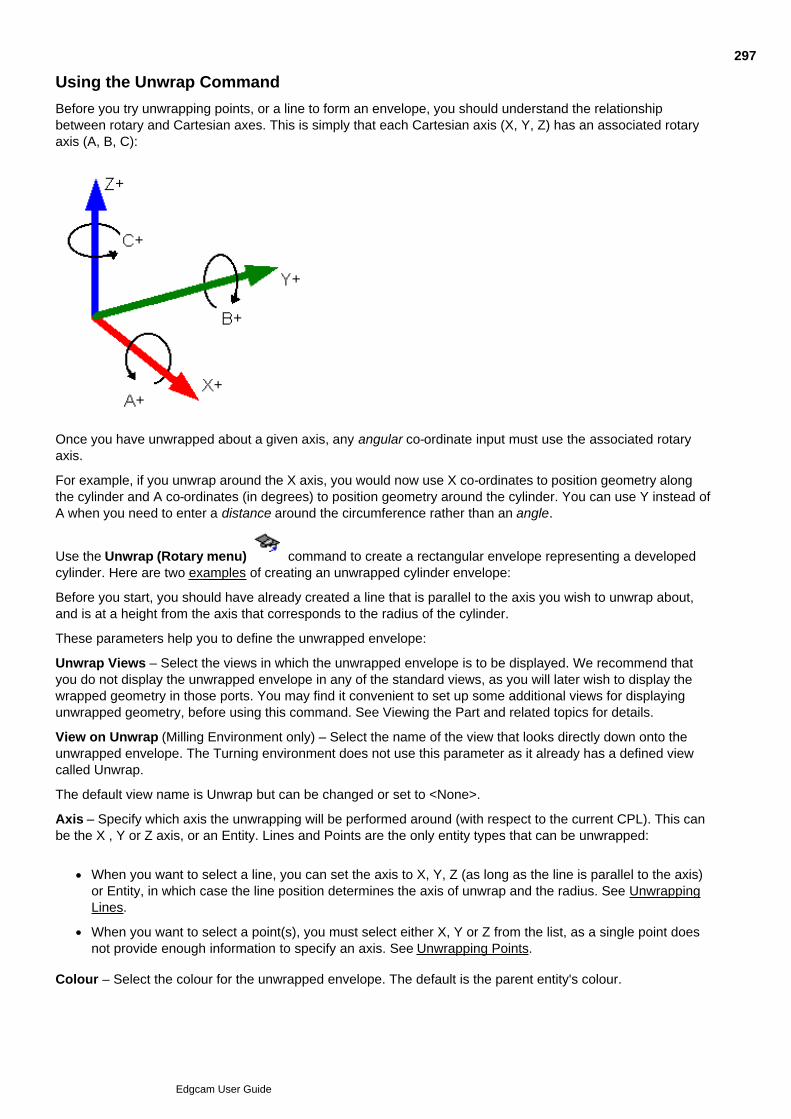
Using the Unwrap Command
Before you try unwrapping points, or a line to form an envelope, you should understand the relationshipbetween rotary and Cartesian axes. This is simply that each Cartesian axis (X, Y, Z) has an associated rotaryaxis (A, B, C):
Once you have unwrapped about a given axis, any angular co-ordinate input must use the associated rotaryaxis.
For example, if you unwrap around the X axis, you would now use X co-ordinates to position geometry alongthe cylinder and A co-ordinates (in degrees) to position geometry around the cylinder. You can use Y instead ofA when you need to enter a distance around the circumference rather than an angle.
Use the Unwrap (Rotary menu) command to create a rectangular envelope representing a developedcylinder. Here are two examples of creating an unwrapped cylinder envelope:
Before you start, you should have already created a line that is parallel to the axis you wish to unwrap about,and is at a height from the axis that corresponds to the radius of the cylinder.
These parameters help you to define the unwrapped envelope:
Unwrap Views – Select the views in which the unwrapped envelope is to be displayed. We recommend thatyou do not display the unwrapped envelope in any of the standard views, as you will later wish to display thewrapped geometry in those ports. You may find it convenient to set up some additional views for displayingunwrapped geometry, before using this command. See Viewing the Part and related topics for details.
View on Unwrap (Milling Environment only) – Select the name of the view that looks directly down onto theunwrapped envelope. The Turning environment does not use this parameter as it already has a defined viewcalled Unwrap.
The default view name is Unwrap but can be changed or set to <None>.
Axis – Specify which axis the unwrapping will be performed around (with respect to the current CPL). This canbe the X , Y or Z axis, or an Entity. Lines and Points are the only entity types that can be unwrapped:
When you want to select a line, you can set the axis to X, Y, Z (as long as the line is parallel to the axis)or Entity, in which case the line position determines the axis of unwrap and the radius. See UnwrappingLines.
When you want to select a point(s), you must select either X, Y or Z from the list, as a single point doesnot provide enough information to specify an axis. See Unwrapping Points.
Colour – Select the colour for the unwrapped envelope. The default is the parent entity's colour.
297
Edgcam User Guide

Style – Select the style or line font for the unwrapped envelope. The default is the parent entity's style.Ensure that your Drawing is configured to have a port showing the Unwrap view, as you need to use this port tocreate the geometry.
The envelope is now created in the selected views and the CPL/Level indicator is updated. The default CPLname is Axis Wrap. The level is the same value as the height of the line above the CPL (radius).
If you digitised more than one line, the level will be the same as the last line you selected.
See Also
Unwrapping Lines
Unwrapping Points
Justifying the Unwrapped Envelope
Showing the Unwrapped Envelope Ruler
298
Edgcam User Guide
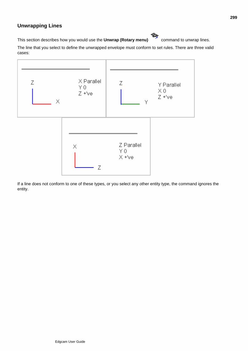
Unwrapping Lines
This section describes how you would use the Unwrap (Rotary menu) command to unwrap lines.
The line that you select to define the unwrapped envelope must conform to set rules. There are three validcases:
If a line does not conform to one of these types, or you select any other entity type, the command ignores theentity.
299
Edgcam User Guide
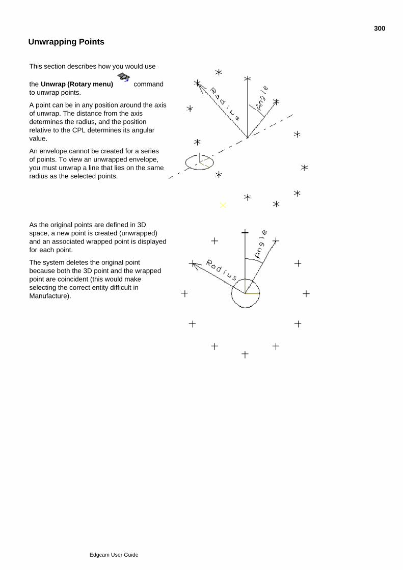
Unwrapping Points
This section describes how you would use
the Unwrap (Rotary menu) commandto unwrap points.
A point can be in any position around the axisof unwrap. The distance from the axisdetermines the radius, and the positionrelative to the CPL determines its angularvalue.
An envelope cannot be created for a seriesof points. To view an unwrapped envelope,you must unwrap a line that lies on the sameradius as the selected points.
As the original points are defined in 3Dspace, a new point is created (unwrapped)and an associated wrapped point is displayedfor each point.
The system deletes the original pointbecause both the 3D point and the wrappedpoint are coincident (this would makeselecting the correct entity difficult inManufacture).
300
Edgcam User Guide
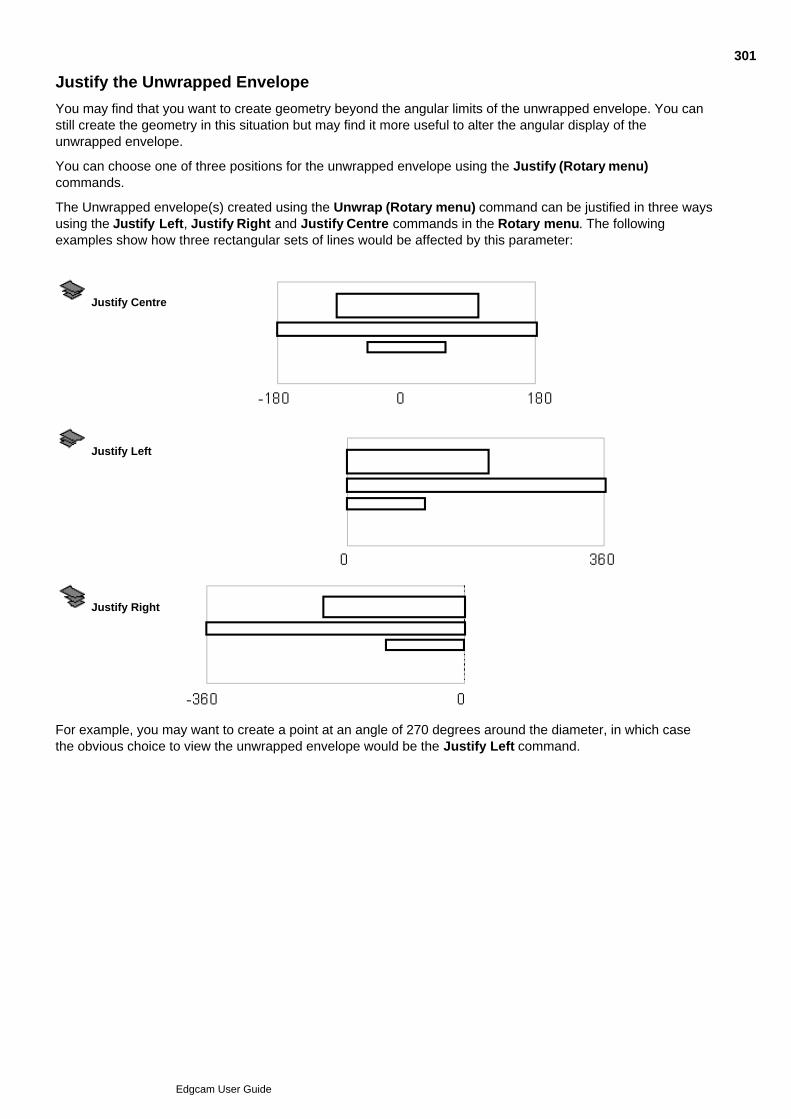
Justify the Unwrapped Envelope
You may find that you want to create geometry beyond the angular limits of the unwrapped envelope. You canstill create the geometry in this situation but may find it more useful to alter the angular display of theunwrapped envelope.
You can choose one of three positions for the unwrapped envelope using the Justify (Rotary menu)commands.
The Unwrapped envelope(s) created using the Unwrap (Rotary menu) command can be justified in three waysusing the Justify Left, Justify Right and Justify Centre commands in the Rotary menu. The followingexamples show how three rectangular sets of lines would be affected by this parameter:
Justify Centre
Justify Left
Justify Right
For example, you may want to create a point at an angle of 270 degrees around the diameter, in which casethe obvious choice to view the unwrapped envelope would be the Justify Left command.
301
Edgcam User Guide

Showing the Unwrapped Envelope Ruler
You can use the Ruler (Rotary menu) command to switch the Unwrap Envelope Ruler on or off. Whenthe Ruler is on, lines are drawn along the bottom unwrapped edge every 15 degrees. The height of thesemarker lines are a proportion of the envelope height.
Here is an example of the Ruler markings (note that the numbers do not appear):
302
Edgcam User Guide
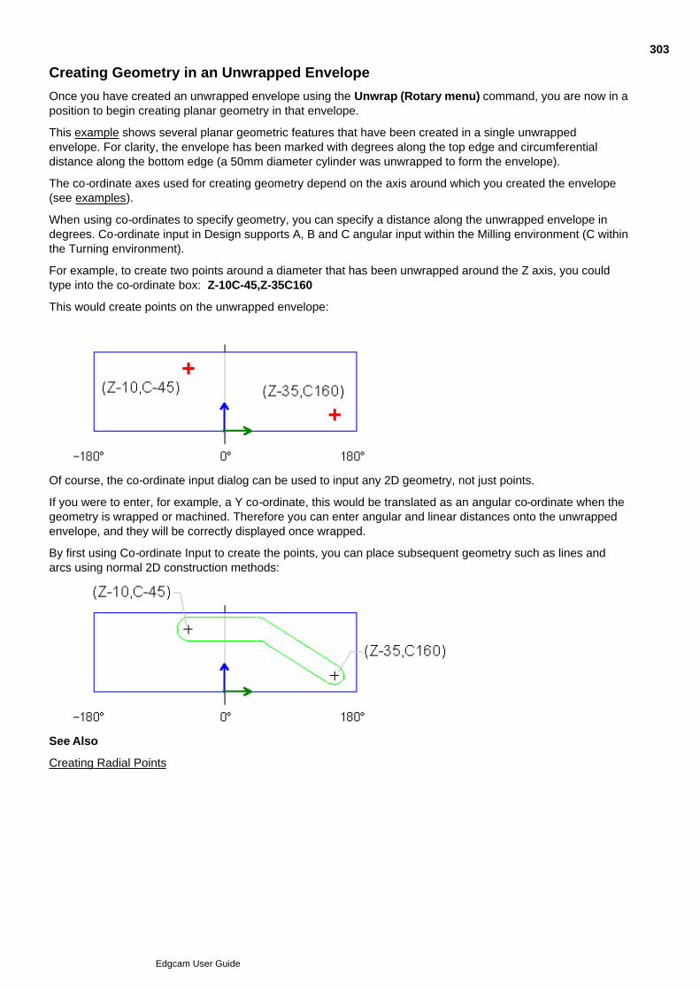
Creating Geometry in an Unwrapped Envelope
Once you have created an unwrapped envelope using the Unwrap (Rotary menu) command, you are now in aposition to begin creating planar geometry in that envelope.
This example shows several planar geometric features that have been created in a single unwrappedenvelope. For clarity, the envelope has been marked with degrees along the top edge and circumferentialdistance along the bottom edge (a 50mm diameter cylinder was unwrapped to form the envelope).
The co-ordinate axes used for creating geometry depend on the axis around which you created the envelope(see examples).
When using co-ordinates to specify geometry, you can specify a distance along the unwrapped envelope indegrees. Co-ordinate input in Design supports A, B and C angular input within the Milling environment (C withinthe Turning environment).
For example, to create two points around a diameter that has been unwrapped around the Z axis, you couldtype into the co-ordinate box: Z-10C-45,Z-35C160
This would create points on the unwrapped envelope:
Of course, the co-ordinate input dialog can be used to input any 2D geometry, not just points.
If you were to enter, for example, a Y co-ordinate, this would be translated as an angular co-ordinate when thegeometry is wrapped or machined. Therefore you can enter angular and linear distances onto the unwrappedenvelope, and they will be correctly displayed once wrapped.
By first using Co-ordinate Input to create the points, you can place subsequent geometry such as lines andarcs using normal 2D construction methods:
See Also
Creating Radial Points
303
Edgcam User Guide

Creating Radial Points
The Radial Points (Rotary menu) command offers a quick method of creating a set of points around acylinder.
The General tab offers the following parameters:
Equal Spacing – Check this box to space all the points out equally around the cylinder. If this is checked, theAngle parameter is greyed out.
Number of Points – Specifies the number of radial points required.
Angle – Specifies the radial angle between each point. This cannot be used with the Equal Spacing parameter.
Initial Angle – Specifies the angle at which to place the first point in the set. The default is 0 degrees.
Radius – Specifies the radius of the wrap.
Axis – Used with the Radius parameter to specify the axis the points are to be wrapped around. If a line orunwrapped envelope has been digitised, the Axis will be ignored.
In addition, the Unwrap and Wrap tabs allow you to select the views in which the planar and radial points willbe displayed.
Unwrap Views – Select the views in which the planar points will be displayed.
Wrap Views – Select the views in which the radial points will be displayed.
Colour – Specifies the colour for the radial points
Style – Specifies the style or font for the radial points.
Once you click on the OK button, you are prompted to “Digitise the centre position of the Radial Points”. Youcan do this by selecting an entity that lies along the selected wrap axis or through co-ordinate input.
304
Edgcam User Guide

Displaying Wrapped Geometry
Wrapping the geometry gives you a clearer 3D view of the component. The wrapping process is like sticking alabel onto a can - the geometry on a rectangular envelope is displayed transformed onto the surface area of acylinder.
You can generate a wrapped representation of planar geometry by using the Wrap (Rotary menu) command.
You can generate wrapped geometry using the Wrap (Rotary menu) command. There are two methodsof using this command:
Wrapping using an envelope
Wrapping directly from planar geometry
305
Edgcam User Guide
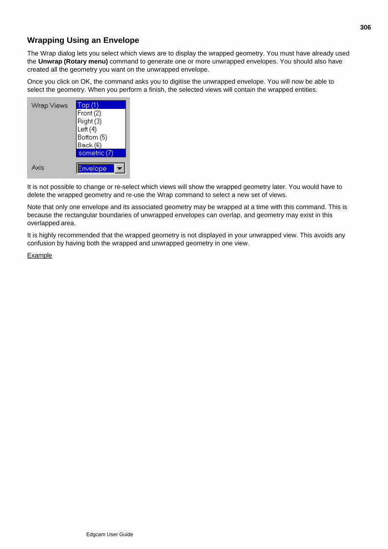
Wrapping Using an Envelope
The Wrap dialog lets you select which views are to display the wrapped geometry. You must have already usedthe Unwrap (Rotary menu) command to generate one or more unwrapped envelopes. You should also havecreated all the geometry you want on the unwrapped envelope.
Once you click on OK, the command asks you to digitise the unwrapped envelope. You will now be able toselect the geometry. When you perform a finish, the selected views will contain the wrapped entities.
It is not possible to change or re-select which views will show the wrapped geometry later. You would have todelete the wrapped geometry and re-use the Wrap command to select a new set of views.
Note that only one envelope and its associated geometry may be wrapped at a time with this command. This isbecause the rectangular boundaries of unwrapped envelopes can overlap, and geometry may exist in thisoverlapped area.
It is highly recommended that the wrapped geometry is not displayed in your unwrapped view. This avoids anyconfusion by having both the wrapped and unwrapped geometry in one view.
Example
306
Edgcam User Guide
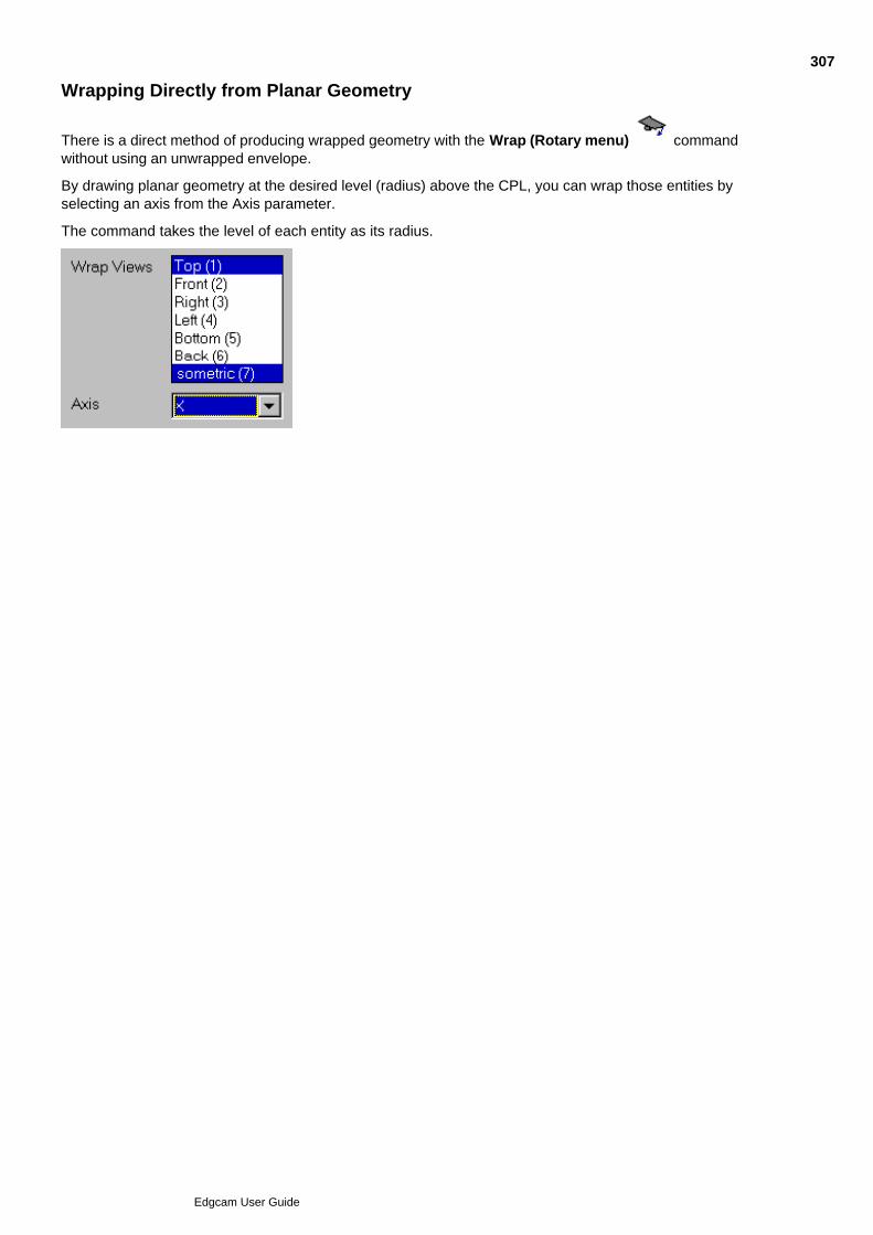
Wrapping Directly from Planar Geometry
There is a direct method of producing wrapped geometry with the Wrap (Rotary menu) commandwithout using an unwrapped envelope.
By drawing planar geometry at the desired level (radius) above the CPL, you can wrap those entities byselecting an axis from the Axis parameter.
The command takes the level of each entity as its radius.
307
Edgcam User Guide

Creating Geometry in the Axial CPL
Within Turning, the system has a predefined CPL called Axial that looks down along the rotary axis. You mustselect CPL Axial before creating any geometry, which otherwise works in the same way as CPL Top in planarmilling.
Within the Milling environment, you can create your own CPLs with any desired orientation. See the CreatingCPLs section for details.
In this example, a PCD (pitch circle diameter) has been created on the back shoulder and a hexagonal nuthead has been produced on the front diameter.
The PCD was created by selecting CPL Axial and specifying the depth by digitising the line representing theshoulder.
You could now create a point at the correct diameter by using the Co-ordinate Input dialog and typing:
X40Y0Z-45
You could now repeat that point around the diameter by using the Transform Rotate (Edit menu) command toproduce your PCD.
The hexagonal nut can be produced in a similar fashion or by using the Polygon (Geometry menu) command.
To create geometry in the axial CPL
308
Edgcam User Guide
Creating a CPL on the End of a Turned Part
This section expands upon part of the sequence of events in Creating Geometry in the Axial CPL. So that youcan easily create geometry on the face of the envelope, you need to create a new construction plane on thisface, centred on the spindle axis. To create the CPL
Select the Create CPL (Geometry menu) command. The parameters for the command appear.1.
Type in a Name for the new CPL.2.
Click in the Origin box to respecify the location of the origin.3.
Set the Dimensions parameter to 3D.4.
Set the Work Plane to Mill (XY).5.
Click on the Reference button.6.
Set the CPL parameter to Axial.7.
Click on OK to accept the parameter values and remove the parameter input box. The parameter box isremoved and you are prompted to digitise a new origin.
8.
Select the Co-ordinate Input command to display the co-ordinates parameter box.9.
Enter the following co-ordinates: X=0 (Absolute), Y=0 (Absolute), Z (Screen Select)10.
Click on OK.11.
Digitise the end of the envelope to set the Z position of the origin of the new CPL.12.
You are now ready to create geometry on the end of the envelope.
309
Edgcam User Guide

Creating Planar Geometry in Turning
This example shows a turned part with a flange placed on the OD (outer diameter). This feature cannot bemachined with Rotary milling, as the tool must move in the Y axis (Planar mode).
To create the geometry relative to the turned part you must first create a CPL.
For example, select Create CPL (Geometry menu) and enter the following parameters:
Click on Reference and specify CPL = Axial
Name = Yaxis
Select Origin
Click on Rotate and specify X Rotation = -90
Dimensions = 3D
By digitising the centreline, a CPL will be created similar to that shown in the above diagram.
This CPL allows you to create geometry at the required orientation.
310
Edgcam User Guide

Viewing the Part as Wireframe
Use Toggle Wireframe in the Display toolbar to switch between a wireframe and a rendered view ofyour part. In wireframe, you only see lines representing edges in the part. In rendered you see the partas a solid.
Alternatively, in the View Properties dialog General tab, set the Display option to Wireframe or Rendered.
A bitmap image is generated which you can save to a file, to view later in other software packages.
Surfaces are rendered using the polygon mesh described with the surface Display parameters U Points and VPoints. Before rendering an image involving surfaces, make sure that these are set correctly.
The base entity colour is used as the base colour for the image.
311
Edgcam User Guide

Using Stock and Fixtures
Fixtures
Fixtures are, for example, the clamps that hold the work piece.
You represent fixtures within Edgecam so that they are visible when simulating, so any collisions with thefixtures can be detected and remedied.
To use fixtures:
Create the fixture in Design mode.1.
As appropriate (and dependent on the machine capabilities) assign the fixture as fixed, or to an axis orspindle.
2.
In Manufacture mode, make sure there is an Update Fixtures instruction (M-Functions menu) before anypart of the sequence which is to use the fixture (so that the fixture is visible in Simulator).
3.
Stock
Stock represents the raw material from which the part is to be machined.
When roughing a boss for example, you need to specify the stock so that all the material 'outside' the boss canbe removed.
To use stock:
Create stock in Design mode.1.
For multi-plane milling assign the fixture as fixed, or to an axis or spindle.2.
Specify the stock as appropriate when creating operations or cycles.3.
312
Edgcam User Guide
Creating Stock and Fixtures
The command Stock/Fixture (Geometry menu) allows you to create stock or a fixture.
For Edgecam Simulator, stock and fixtures can be cuboid, cylindrical, defined by a profile or digitised from solidmodels (this option requires a Solid Machinist licence).
(Stock and fixtures can also be used by Verify. Note that Verify is obsolete functionality.)
For a detailed explanation of individual parameters, please refer to the context sensitive help for the dialog.
Entries for Stock and fixture items appear in the Features Window. When you move the mouse over anentry, the item becomes highlighted in the graphics area. The layer and colour properties of stock and fixtureitems can be edited using the appropriate commands in the Shortcut menu (right-hand mouse click).
Automatic Stock
You can automatically create stock by checking the Automatic Stock box in the Stock/Fixture dialog.
There are options for offsetting boxes in X, Y and Z.
In the turning environment, a cylinder aligned with the turning axis is created. In order to do this, you will needto use the standard TURN CPL or a user defined CPL where the solid has been oriented accordingly. Forcylinder stock, extension parameters are available which allow the radius of the stock or the length at eitherend to be extended.
Please note that offsets are incremental and not absolute.
You can also create stock automatically using Auto-Stock in the Design toolbar (though this does notgive you the offset options).
Displaying the stock and fixtures
As for any other entity, the display of stock and fixtures is controlled by layers. When using the dialog to createstock or fixtures, you can opt for stock and fixtures to be created in their own Stock or Fixture layer (which iscreated if necessary), or in any layer of your choice.
Use Toggle Stock in the Display toolbar to switch between:
Solid fixtures, translucent stock.
Wireframe fixtures, wireframe stock.
Alternatively click on the View caption (bottom left of Graphics Area) and in the subsequent View Propertiesdialog click Translucent Stock.
Creating a library of fixture parts
When creating stock and fixture entities an attribute is set and saved with the part. Therefore it is possible tosave drawings of clamps, vices, rotary tables, tombstones, chucks etc with their fixture attribute set. Whenthese parts are inserted they will have their fixture attribute set and will be displayed as fixtures in the FeaturesWindow. This means that fixtures can be inserted into a range of parts without further user intervention.
See Also
Creating a Box Stock or Fixture
Creating a Cylindrical Stock or Fixture
Creating a Profile Stock or Fixture
Stock and Fixtures from Solid Models
313
Edgcam User Guide

Fixtures in Manufacture
Transforming Stock and Fixtures
314
Edgcam User Guide
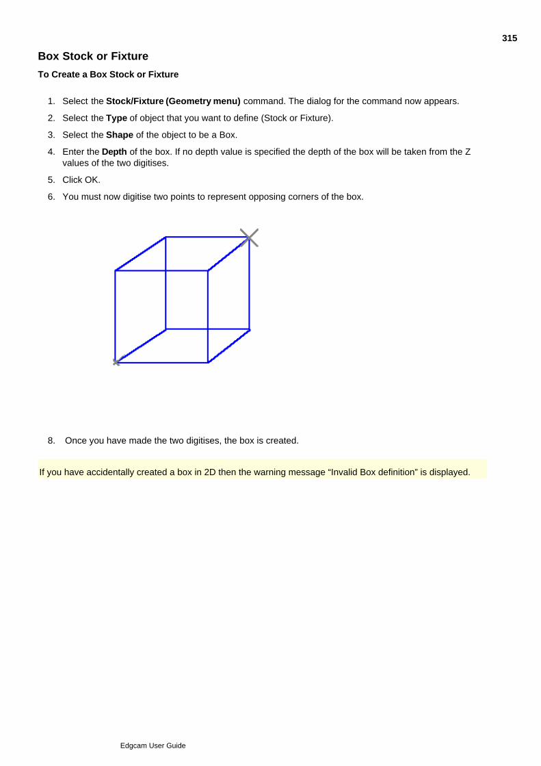
Box Stock or Fixture
To Create a Box Stock or Fixture
Select the Stock/Fixture (Geometry menu) command. The dialog for the command now appears.1.
Select the Type of object that you want to define (Stock or Fixture).2.
Select the Shape of the object to be a Box.3.
Enter the Depth of the box. If no depth value is specified the depth of the box will be taken from the Zvalues of the two digitises.
4.
Click OK.5.
You must now digitise two points to represent opposing corners of the box.6.
Once you have made the two digitises, the box is created.8.
If you have accidentally created a box in 2D then the warning message “Invalid Box definition” is displayed.
315
Edgcam User Guide
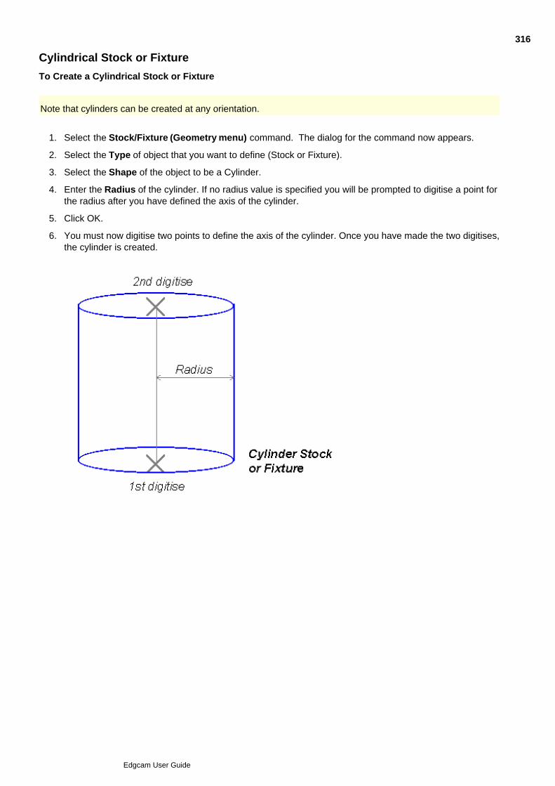
Cylindrical Stock or Fixture
To Create a Cylindrical Stock or Fixture
Note that cylinders can be created at any orientation.
Select the Stock/Fixture (Geometry menu) command. The dialog for the command now appears.1.
Select the Type of object that you want to define (Stock or Fixture).2.
Select the Shape of the object to be a Cylinder.3.
Enter the Radius of the cylinder. If no radius value is specified you will be prompted to digitise a point forthe radius after you have defined the axis of the cylinder.
4.
Click OK.5.
You must now digitise two points to define the axis of the cylinder. Once you have made the two digitises,the cylinder is created.
6.
316
Edgcam User Guide
Profile Stock or Fixture
To Create a Profile Stock or Fixture
Select the Stock/Fixture (Geometry menu) command. The dialog for the command now appears.1.
Select the Type of object to be Stock or Fixture.2.
Select the Shape of the stock to be a Profile.3.
Enter the Depth of the profile. This is the height of the top of the profile above the level of the profile. Ifno depth value is specified you will be prompted to digitise a point to define the depth of the profile beforebeing able to select the points on the profile.
4.
Click OK.5.
You are now prompted to digitise a closed 2D profile. The initial level of the profile is taken from the firstdigitise. The height of the top of the profile is the level plus the specified Depth.
6.
Please note that edges and faces should not cross over or exactly meet as the Simulator converts theprofile into a solid and this will cause an illegal operation.
Please note that profile stock can only be created in CPL Top otherwise it is displayed incorrectly inEdgecam Verify.
317
Edgcam User Guide
Stock and Fixture from Solid Models
Requires a Solid Machinist licence
Stock and fixtures for the Edgecam Simulator can be defined by digitising a solid model.
Select the Stock/Fixture (Geometry menu) command. The dialog for the command now appears.1.
Set the Shape parameter to Digitise.2.
Select the Type of object to be Stock or Fixture.3.
You will be prompted to select the entities to define the stock/fixture.4.
To use fixtures in manufacture and display them in the Simulator see Fixtures in Manufacture and theSimulator.
318
Edgcam User Guide
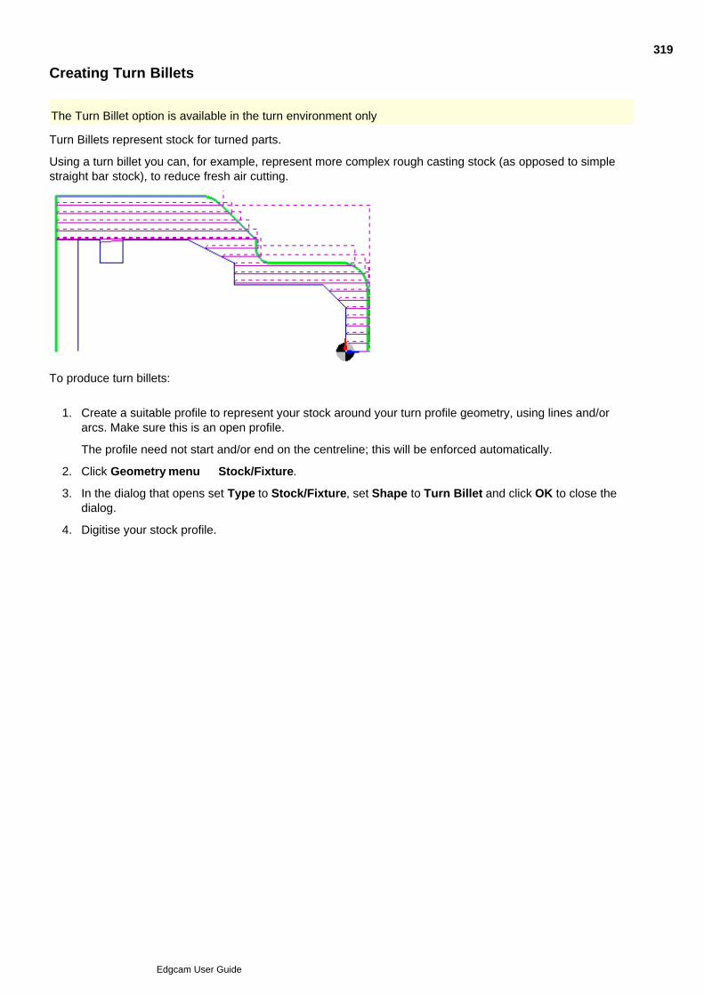
Creating Turn Billets
The Turn Billet option is available in the turn environment only
Turn Billets represent stock for turned parts.
Using a turn billet you can, for example, represent more complex rough casting stock (as opposed to simplestraight bar stock), to reduce fresh air cutting.
To produce turn billets:
Create a suitable profile to represent your stock around your turn profile geometry, using lines and/orarcs. Make sure this is an open profile.
The profile need not start and/or end on the centreline; this will be enforced automatically.
1.
Click Geometry menu Stock/Fixture.2.
In the dialog that opens set Type to Stock/Fixture, set Shape to Turn Billet and click OK to close thedialog.
3.
Digitise your stock profile.4.
319
Edgcam User Guide
Updating Fixtures
Fixtures will not appear in the Simulator until after an 'Update Fixtures' instruction.
To create this instruction in the sequence, use the Update Stock/Fixtures command in the M-Functions menu.
You use Update Stock/Fixtures to create the initial fixture setup, and if necessary to subsequently modify itduring the sequence (as clamps need to be moved for example).
Note that this command does not result in a pause being placed into the CNC code. To allow theoperator to move the fixtures you will need to use M-Functions Menu > Stop Type (and perhaps M-Functions Menu > Comment.
The command prompts you to select fixtures to be added to the setup. Pick these as required and confirm theselection with a right-hand mouse click. The command then prompts you to select fixtures to be removed fromthe setup. Pick these as required and confirm the selection with a right-hand mouse click or press the returnkey for none.
Notes
From the Sequence Window you can edit the digitised input for the command if required.
Rapid Result does not support fixtures and nominated fixtures will be ignored.
We do not recommend rationalising a machining sequence that contains multiple Update Fixturecommands.
Please note that self-intersecting triangles and open solids are not suitable for simulation as Booleanoperations are impossible on 'corrupt solids'. A warning message will be issued when the part is loaded intoEdgecam Simulator. Edgecam Simulator will carry on simulating the part when the warning is accepted, butwill fail when it reaches the problem area.
320
Edgcam User Guide
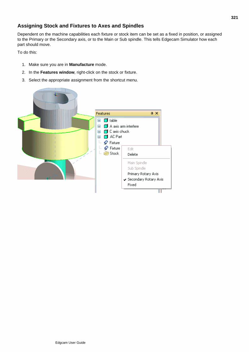
Assigning Stock and Fixtures to Axes and Spindles
Dependent on the machine capabilities each fixture or stock item can be set as a fixed in position, or assignedto the Primary or the Secondary axis, or to the Main or Sub spindle. This tells Edgecam Simulator how eachpart should move.
To do this:
Make sure you are in Manufacture mode.1.
In the Features window, right-click on the stock or fixture.2.
Select the appropriate assignment from the shortcut menu.3.
321
Edgcam User Guide
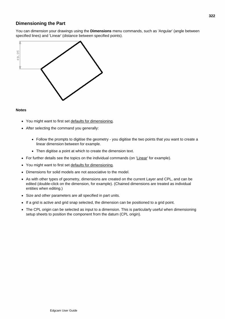
Dimensioning the Part
You can dimension your drawings using the Dimensions menu commands, such as 'Angular' (angle betweenspecified lines) and 'Linear' (distance between specified points).
Notes
You might want to first set defaults for dimensioning.
After selecting the command you generally:
Follow the prompts to digitise the geometry - you digitise the two points that you want to create alinear dimension between for example.
Then digitise a point at which to create the dimension text.
For further details see the topics on the individual commands (on 'Linear' for example).
You might want to first set defaults for dimensioning.
Dimensions for solid models are not associative to the model.
As with other types of geometry, dimensions are created on the current Layer and CPL, and can beedited (double-click on the dimension, for example). (Chained dimensions are treated as individualentities when editing.)
Size and other parameters are all specified in part units.
If a grid is active and grid snap selected, the dimension can be positioned to a grid point.
The CPL origin can be selected as input to a dimension. This is particularly useful when dimensioningsetup sheets to position the component from the datum (CPL origin).
322
Edgcam User Guide
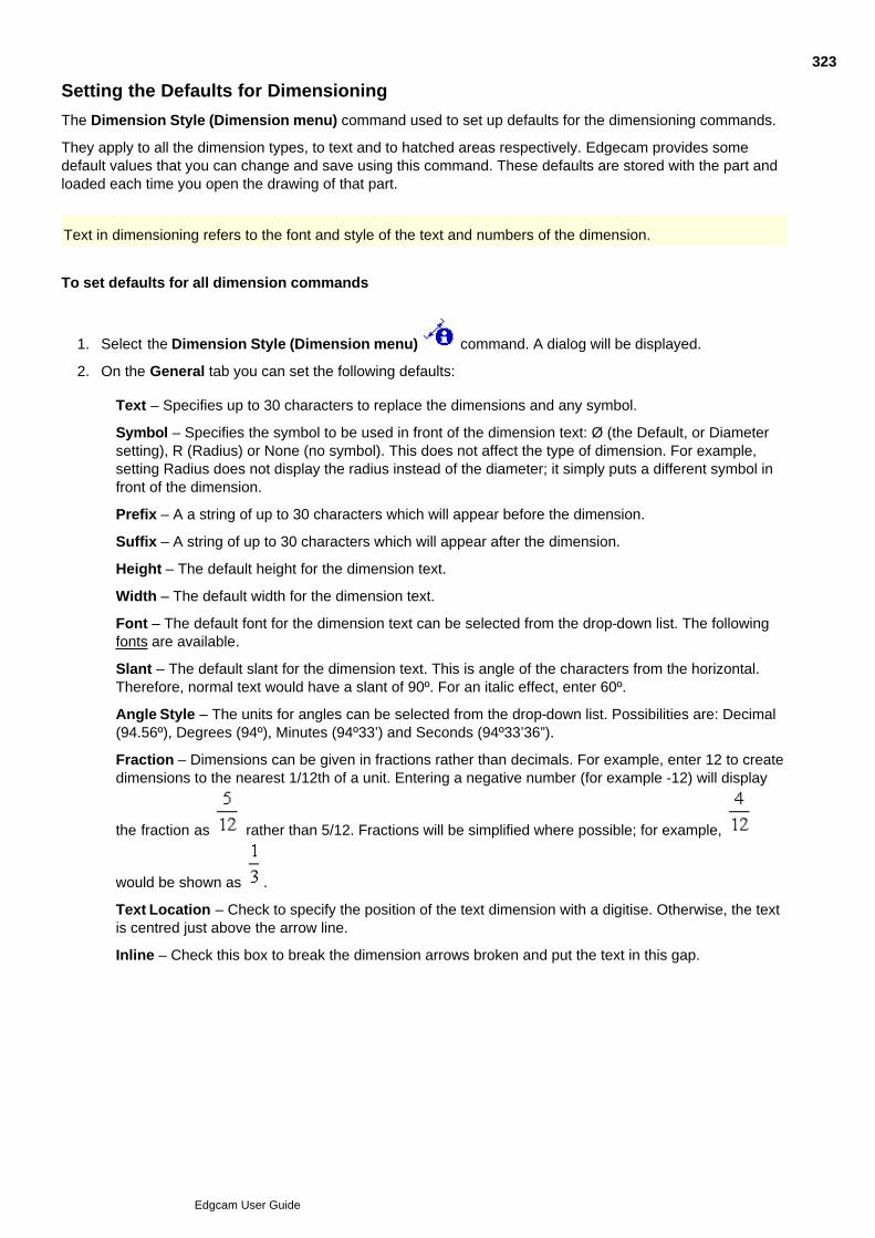
Setting the Defaults for Dimensioning
The Dimension Style (Dimension menu) command used to set up defaults for the dimensioning commands.
They apply to all the dimension types, to text and to hatched areas respectively. Edgecam provides somedefault values that you can change and save using this command. These defaults are stored with the part andloaded each time you open the drawing of that part.
Text in dimensioning refers to the font and style of the text and numbers of the dimension.
To set defaults for all dimension commands
Select the Dimension Style (Dimension menu) command. A dialog will be displayed.1.
On the General tab you can set the following defaults:2.
Text – Specifies up to 30 characters to replace the dimensions and any symbol.
Symbol – Specifies the symbol to be used in front of the dimension text: Ø (the Default, or Diametersetting), R (Radius) or None (no symbol). This does not affect the type of dimension. For example,setting Radius does not display the radius instead of the diameter; it simply puts a different symbol infront of the dimension.
Prefix – A a string of up to 30 characters which will appear before the dimension.
Suffix – A string of up to 30 characters which will appear after the dimension.
Height – The default height for the dimension text.
Width – The default width for the dimension text.
Font – The default font for the dimension text can be selected from the drop-down list. The followingfonts are available.
Slant – The default slant for the dimension text. This is angle of the characters from the horizontal.Therefore, normal text would have a slant of 90º. For an italic effect, enter 60º.
Angle Style – The units for angles can be selected from the drop-down list. Possibilities are: Decimal(94.56º), Degrees (94º), Minutes (94º33’) and Seconds (94º33’36”).
Fraction – Dimensions can be given in fractions rather than decimals. For example, enter 12 to createdimensions to the nearest 1/12th of a unit. Entering a negative number (for example -12) will display
the fraction as rather than 5/12. Fractions will be simplified where possible; for example,
would be shown as .
Text Location – Check to specify the position of the text dimension with a digitise. Otherwise, the textis centred just above the arrow line.
Inline – Check this box to break the dimension arrows broken and put the text in this gap.
323
Edgcam User Guide

If you want the text of the dimensions to always be horizontal, select the Horizontal Text check box. Ifthe check box is not selected, the text is drawn parallel to the dimension line.
Select the Arrow tab to display the Arrow parameters. You can set the following defaults:3.
Select Tolerance tab to display the Tolerance parameters. You can set the following defaults:4.
Click OK to accept the parameter settings for the command.5.
324
Edgcam User Guide
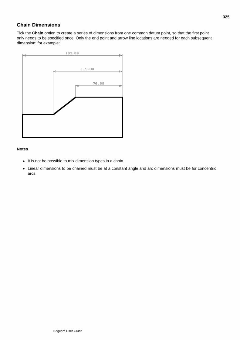
Chain Dimensions
Tick the Chain option to create a series of dimensions from one common datum point, so that the first pointonly needs to be specified once. Only the end point and arrow line locations are needed for each subsequentdimension; for example:
Notes
It is not be possible to mix dimension types in a chain.
Linear dimensions to be chained must be at a constant angle and arc dimensions must be for concentricarcs.
325
Edgcam User Guide
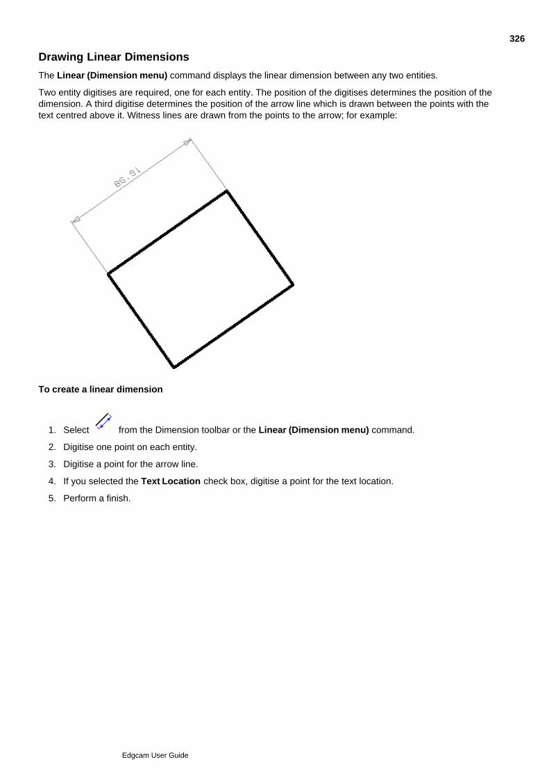
Drawing Linear Dimensions
The Linear (Dimension menu) command displays the linear dimension between any two entities.
Two entity digitises are required, one for each entity. The position of the digitises determines the position of thedimension. A third digitise determines the position of the arrow line which is drawn between the points with thetext centred above it. Witness lines are drawn from the points to the arrow; for example:
To create a linear dimension
Select from the Dimension toolbar or the Linear (Dimension menu) command. 1.
Digitise one point on each entity.2.
Digitise a point for the arrow line.3.
If you selected the Text Location check box, digitise a point for the text location.4.
Perform a finish.5.
326
Edgcam User Guide

Drawing Horizontal Dimensions
The Horizontal (Dimension menu) command displays linear dimensions with a horizontal distance to thecurrent CPL.
To create a horizontal dimension
Select from the Dimension toolbar or the Horizontal (Dimension menu) command. 1.
Digitise one point on each entity.2.
Digitise a point for the arrow line.3.
If you selected the Text Location check box, digitise a point for the text location.4.
Perform a finish.5.
327
Edgcam User Guide
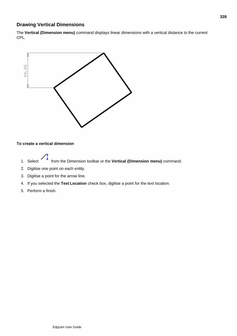
Drawing Vertical Dimensions
The Vertical (Dimension menu) command displays linear dimensions with a vertical distance to the currentCPL.
To create a vertical dimension
Select from the Dimension toolbar or the Vertical (Dimension menu) command. 1.
Digitise one point on each entity.2.
Digitise a point for the arrow line.3.
If you selected the Text Location check box, digitise a point for the text location.4.
Perform a finish.5.
328
Edgcam User Guide

Drawing Angular Dimensions
The Angular (Dimension menu) command displays the angle between two digitised line entities.
Two digitises are required, one for each line. The position of the digitises on the lines affects the dimensionedangle, as does the position of the third (free) digitise.
To create an angular dimension
Select from the Dimension toolbar or the Angular (Dimension menu) command.1.
Digitise one point on each line. The location of the digitises determines which angle is dimensioned (seeexamples).
2.
Digitise a point to position the arrows (see example) . The position of this digitise determines if the insideor outside angle is dimensioned.
3.
If you selected the Text Location check box, digitise a point for the text location. If you chose to displaywitness lines, witness lines may be added to extend the lines out to the location of the text (depending onwhere you digitise) (see example).
4.
Perform a finish.5.
329
Edgcam User Guide
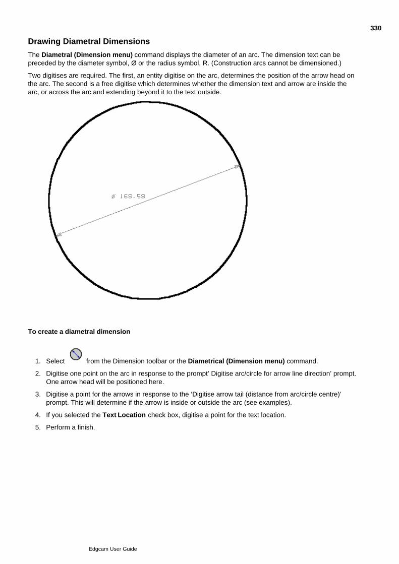
Drawing Diametral Dimensions
The Diametral (Dimension menu) command displays the diameter of an arc. The dimension text can bepreceded by the diameter symbol, Ø or the radius symbol, R. (Construction arcs cannot be dimensioned.)
Two digitises are required. The first, an entity digitise on the arc, determines the position of the arrow head onthe arc. The second is a free digitise which determines whether the dimension text and arrow are inside thearc, or across the arc and extending beyond it to the text outside.
To create a diametral dimension
Select from the Dimension toolbar or the Diametrical (Dimension menu) command.1.
Digitise one point on the arc in response to the prompt’ Digitise arc/circle for arrow line direction’ prompt.One arrow head will be positioned here.
2.
Digitise a point for the arrows in response to the ‘Digitise arrow tail (distance from arc/circle centre)’prompt. This will determine if the arrow is inside or outside the arc (see examples).
3.
If you selected the Text Location check box, digitise a point for the text location.4.
Perform a finish.5.
330
Edgcam User Guide
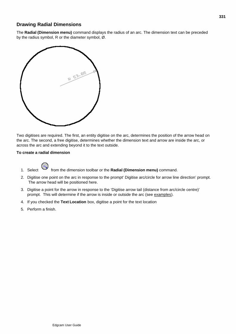
Drawing Radial Dimensions
The Radial (Dimension menu) command displays the radius of an arc. The dimension text can be precededby the radius symbol, R or the diameter symbol, Ø.
Two digitises are required. The first, an entity digitise on the arc, determines the position of the arrow head onthe arc. The second, a free digitise, determines whether the dimension text and arrow are inside the arc, oracross the arc and extending beyond it to the text outside.
To create a radial dimension
Select from the dimension toolbar or the Radial (Dimension menu) command.1.
Digitise one point on the arc in response to the prompt’ Digitise arc/circle for arrow line direction’ prompt. The arrow head will be positioned here.
2.
Digitise a point for the arrow in response to the ‘Digitise arrow tail (distance from arc/circle centre)’prompt. This will determine if the arrow is inside or outside the arc (see examples).
3.
If you checked the Text Location box, digitise a point for the text location4.
Perform a finish.5.
331
Edgcam User Guide

Drawing Arrows
You can create an arrow line on your drawing using the Arrow (Dimension menu) command. The arrow canbe constructed from one or more straight line segments.
To create an arrow line
Select from the Dimension toolbar or the Arrow (Dimension menu) command.1.
Digitise a point for the arrow head.2.
Digitise one or more points for the arrow line. These do not have to be linear.3.
Perform a finish.4.
332
Edgcam User Guide

Hatching an Area
You can cross hatch (shade in) an area for clarity. This area can contain ‘islands’; that is, areas that will not becross hatched. The area can be bounded by any combination of lines arcs, curves, construction entities,continuous or group entities.
You can alter the angle and line spacing defaults, if required.
To hatch an area
Select the button from the Dimension toolbar or the Hatch Area (Dimension menu) command. The Hatch dialog box is displayed.
1.
If required, update the default Angle of the hatch lines and Line Spacing.2.
Click OK to accept the parameters for the command.3.
Digitise a point on each boundary of the area. If islands are to be left, digitise them well before finishingthe command. Adjacent entities must have coincident endpoints.
4.
Please note that boundaries can be windowed and chained but you should be careful to avoid ambiguousconstructions as these may be misinterpreted.
Perform a finish.5.
333
Edgcam User Guide

Accuracy of Imported CAD Data
The accuracy of the CAD model that is imported into Edgecam is a crucial element in defining the accuracyto which the model can be machined. To ensure that the model is machined to the required accuracy inEdgecam you should ensure that the model is created in the CAD system to at least the desired machiningtolerance.
Also see the notes in Loading of Granite Models (Solid Machinist for Granite licence only)
Please refer to the documentation of your CAD system on how to check and/or configure the accuracy of themodel to be exported.
334
Edgcam User Guide
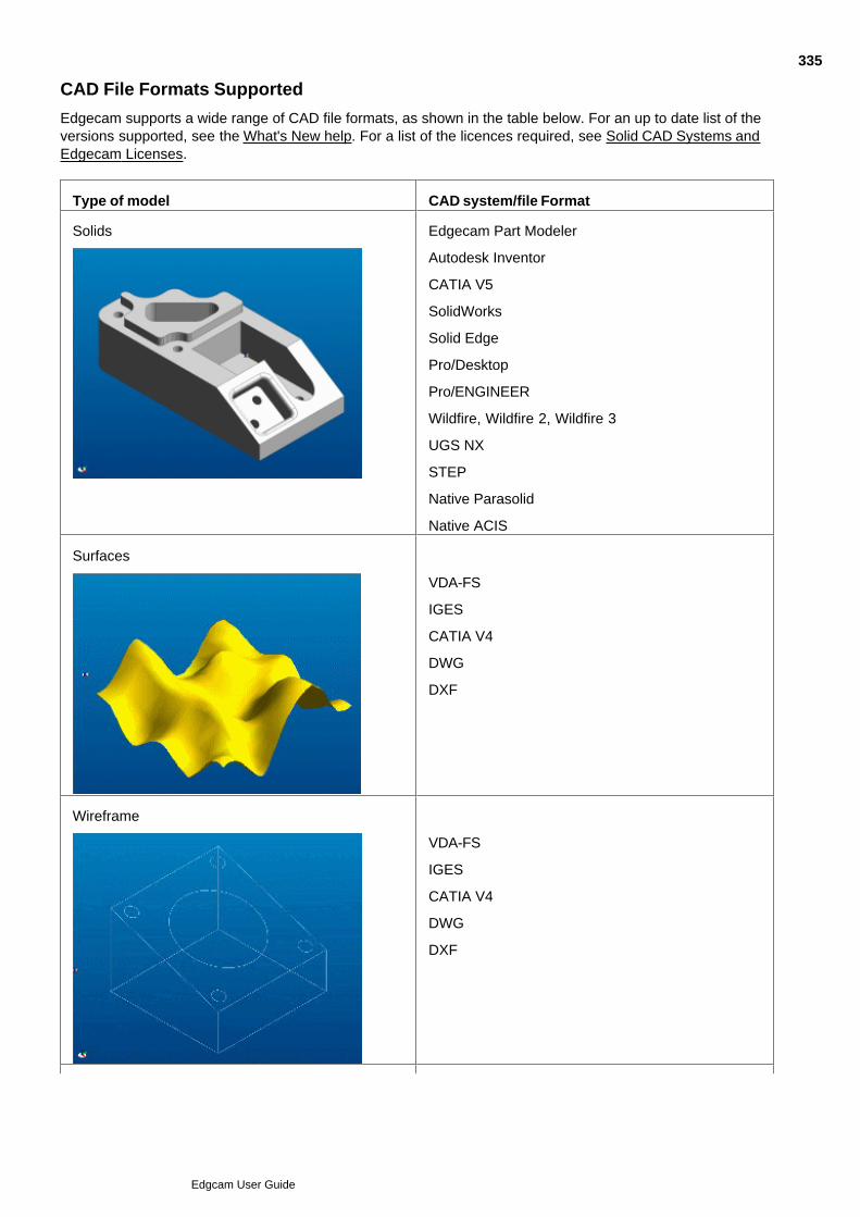
CAD File Formats Supported
Edgecam supports a wide range of CAD file formats, as shown in the table below. For an up to date list of theversions supported, see the What's New help. For a list of the licences required, see Solid CAD Systems andEdgecam Licenses.
Type of model CAD system/file Format
Solids Edgecam Part Modeler
Autodesk Inventor
CATIA V5
SolidWorks
Solid Edge
Pro/Desktop
Pro/ENGINEER
Wildfire, Wildfire 2, Wildfire 3
UGS NX
STEP
Native Parasolid
Native ACIS
Surfaces
VDA-FS
IGES
CATIA V4
DWG
DXF
Wireframe
VDA-FS
IGES
CATIA V4
DWG
DXF
335
Edgcam User Guide

STL
336
Edgcam User Guide

Using the New IGES Importer
On selecting an IGES file for opening in the normal way, the dialog below opens (or an alternative, asexplained below). You can also access this help using the Help button in the dialog:
337
Edgcam User Guide

Using the Standard IGES Importer
On selecting an IGES file for opening in the normal way, the dialog below opens (or an alternative, asexplained). You can also access this help using the Help button in the dialog:
338
Edgcam User Guide

Using the New IGES Exporter
When using Save As with the file type of IGES Files (*.igs;*.iges) you use this dialog (or an alternative asexplained). You can also access this help using the Help button in the dialog:
339
Edgcam User Guide

Using the Standard IGES Exporter
When using Save As with the file type of IGES Files (*.igs;*.iges) you use this dialog (or an alternative - asexplained). You can also access this help using the Help button in the dialog:
340
Edgcam User Guide

Exporting IGES Files from CATIA
Most CAD systems provide different output options for the exporting of IGES files. For best results whenloading a CATIA IGES file into Edgecam we recommend the following output options in CATIA:
Entity Type Setting
IGES level Standard
Curves and Surfaces B Spline
Conics B Spline
Canonical Surfaces B Spline
341
Edgcam User Guide

Entity-Related Problems
Different CAD/CAM systems may create entities that exist successfully in the Edgecam 3D part model, butproblems can still occur. Some common problems include:
Repeated entities and/or entities with the same end points
The major problem is that these entities may stop a Chain.
Copy one of these double entities to an hidden layer and redraw the part using one of the toolbar icons or theRedraw (View menu) command to reveal the underlying entities.
Consecutive entities with inaccurate end points
A minor problem to resolve; use the Trim (Edit menu) command to trim the end points together.
Continuous entities in IGES
To allow access to the underlying entities use the Explode (Edit menu) command. All the entities will then beselectable as single entities.
Surfaces from other CAD/CAM systems
Always verify a surface type using the Entity (Verify menu) command to ensure that the IGES transfer hasmaintained the surface type. Problems can occur when the surface was defined in the sender's CAD/CAMsystem as a ruled surface but may be transferred in the IGES file as a different type. You need to identify thesurface in Edgecam so that you can apply entity masking or selection.
Transformed entities
Ensure that the transferred part is at an origin known to you. Many design engineers will set a local origin fortheir convenience.
For example, a car may have the origin of all the major components relative to the front bumper, or an aircraftmay have its major components relative to the centre of gravity. To resolve this problem, translate the part tothe origin prior to any machining operations.
Loading speed of IGES entities
Problems with the loading speed of IGES can be caused by the relationship between the units of some IGESentities and the Edgecam system tolerance. In these cases the 'Conversion Tolerance' option on theAdvanced tab of the IGES load dialog can be used to override the system tolerance to ensure that the file isloaded correctly. The default value for the conversion tolerance is the system tolerance value that is specifiedin the defaults file.
342
Edgcam User Guide
Importing VDA-FS Files
The ability to open VDA-FS files is included in all Edgecam system licences.
To load a VDA-FS format file into Edgecam, use the Open (File menu) command and set the List Files ofType parameter to VDA-FS.
The following table lists all the VDA-FS entities which are currently supported by Edgecam:
Command Word VDA Element Edgecam Entity
POINT Point Point
PSET Point sequence One or more lines
MDI Point vector sequence not supported
CIRCLE Circle/circular arc Arc
CURVE Curve Spline curve
SURF Surface Spline surface
CONS Curve on surface Surface curve
FACE Bounded surface Trimmed surface
TOP Topology of surface not supported
343
Edgcam User Guide

Importing MicroStation Files
To import an IGDS file into Edgecam, use the Open (File menu) command and set the List Files of Typeparameter to DGN. Once you have selected the file name of the .dgn file, a dialog box displays theseparameters:
Dimensions – Select this option to include dimensioning information in the file.
Surfaces – Select this option to include surface data in the file.
Units – Select the output part units.
Log File – Specify the type of log file to be produced to record the .dgn file output process.
Name – Specify a name for the report file.
Verbose – Select this option for the log file to contain more detailed information.
This table lists all the MicroStation IGDS entities which are currently supported by Edgecam, with details of howthey are interpreted, where applicable.
344
Edgcam User Guide

Loading AutoCAD Files
Open AutoCAD files as normal.
How the file opens depends on the setting of Options menu Preferences General tab NewDWG/DXF Import:
When checked the file opens directly in Edgecam. This is using the Use 'New' importer required for 2004and later format AutoCAD files. See below for more details.
When unchecked the file opens via a dialog. This is using the 'Standard' importer that can openAutoCAD files prior to the 2004 format. This is the default.
New loader notes
See this list of supported entity types...
ACIS entities are not imported.
345
Edgcam User Guide
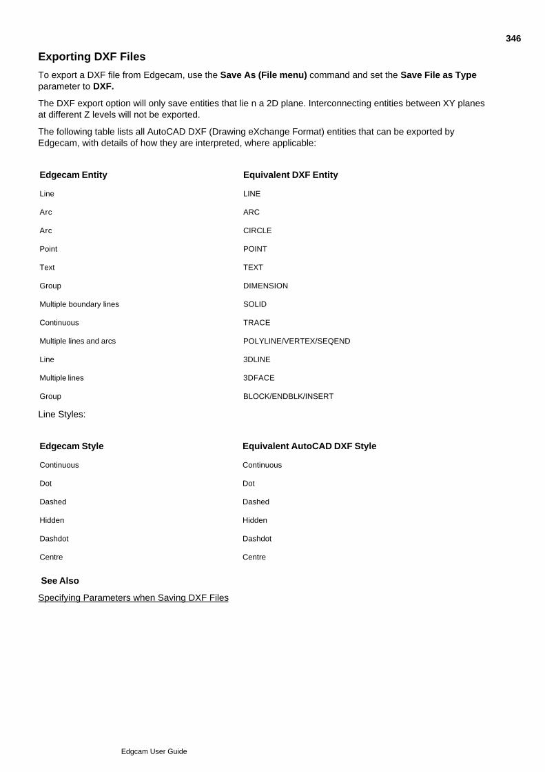
Exporting DXF Files
To export a DXF file from Edgecam, use the Save As (File menu) command and set the Save File as Typeparameter to DXF.
The DXF export option will only save entities that lie n a 2D plane. Interconnecting entities between XY planesat different Z levels will not be exported.
The following table lists all AutoCAD DXF (Drawing eXchange Format) entities that can be exported byEdgecam, with details of how they are interpreted, where applicable:
Edgecam Entity Equivalent DXF Entity
Line LINE
Arc ARC
Arc CIRCLE
Point POINT
Text TEXT
Group DIMENSION
Multiple boundary lines SOLID
Continuous TRACE
Multiple lines and arcs POLYLINE/VERTEX/SEQEND
Line 3DLINE
Multiple lines 3DFACE
Group BLOCK/ENDBLK/INSERT
Line Styles:
Edgecam Style Equivalent AutoCAD DXF Style
Continuous Continuous
Dot Dot
Dashed Dashed
Hidden Hidden
Dashdot Dashdot
Centre Centre
See Also
Specifying Parameters when Saving DXF Files
346
Edgcam User Guide

Specifying Parameters when Saving DXF Files
Once you have specified the file name of the DXF file, a dialog box is displayed which contains this parameter:
Dimensioning – Select this parameter to include Edgecam dimension entities in the output file.
The output is 2D; that is, X and Y co-ordinates plus elevations.
347
Edgcam User Guide

Loading STL Files
To load a STL format file into Edgecam, use the Open (File menu) command and set the List Files of Typeparameter to STL.
You can also insert an STL file using the Insert, STL File (File menu) command.
When opening or inserting an STL file, Edgecam will automatically generate a bounding box. The STL file willbe loaded/inserted using the current layer, colour and font for the solid.
You can intellisnap the corner points of the triangles which is useful for creating boundaries and digitising cycledepth parameters.
STL entities can be rotated, translated, mirrored and scaled using the appropriate Edit, Transform commands.For large STL models, any transformation may take some time. Please note that scaling a part will scale thetolerance to which the triangles represent the original model.
Please note that STL files can only be machined using surface cycles (except Surface Areaclear andSurface Lace).
348
Edgcam User Guide
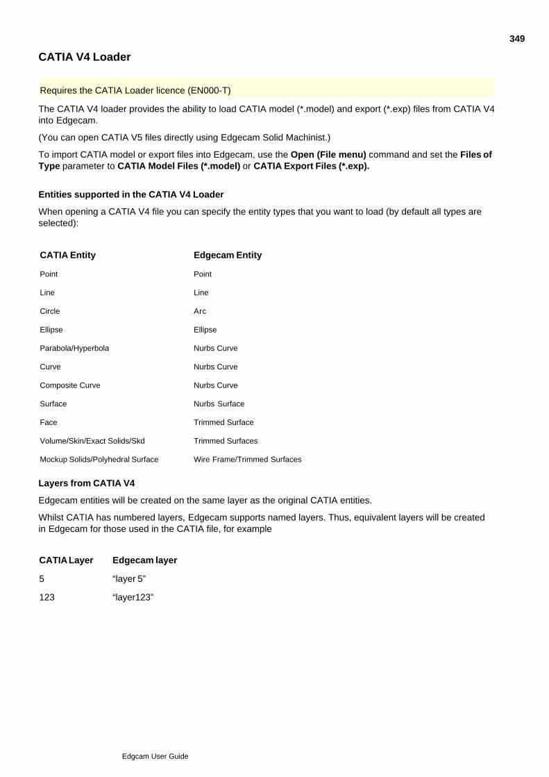
CATIA V4 Loader
Requires the CATIA Loader licence (EN000-T)
The CATIA V4 loader provides the ability to load CATIA model (*.model) and export (*.exp) files from CATIA V4into Edgecam.
(You can open CATIA V5 files directly using Edgecam Solid Machinist.)
To import CATIA model or export files into Edgecam, use the Open (File menu) command and set the Files ofType parameter to CATIA Model Files (*.model) or CATIA Export Files (*.exp).
Entities supported in the CATIA V4 Loader
When opening a CATIA V4 file you can specify the entity types that you want to load (by default all types areselected):
CATIA Entity Edgecam Entity
Point Point
Line Line
Circle Arc
Ellipse Ellipse
Parabola/Hyperbola Nurbs Curve
Curve Nurbs Curve
Composite Curve Nurbs Curve
Surface Nurbs Surface
Face Trimmed Surface
Volume/Skin/Exact Solids/Skd Trimmed Surfaces
Mockup Solids/Polyhedral Surface Wire Frame/Trimmed Surfaces
Layers from CATIA V4
Edgecam entities will be created on the same layer as the original CATIA entities.
Whilst CATIA has numbered layers, Edgecam supports named layers. Thus, equivalent layers will be createdin Edgecam for those used in the CATIA file, for example
CATIA Layer Edgecam layer
5 “layer 5”
123 “layer123”
349
Edgcam User Guide

Edgecam Solid Machinist
Requires Edgecam Solid Machinist licence
Edgecam Solid Machinist provides the ability to directly load and machine solid models without the need fortranslation. Solid Machinist supports both prismatic and surface milling including multi-plane.
You can machine the solid directly, or you can create 'features' from the solid, and machine these.
Associativity with the model is retained, and a Reload command is available from the Solids menu or toolbarwhich allows you to reload an updated model into Edgecam. Edgecam will automatically regenerate thefeatures to reflect the changes in the design model.
Additional geometry can be created around the solid model for manufacturing purposes by using standardEdgecam design tools.
350
Edgcam User Guide

Creating Geometry from Solids
Use Solids menu Geometry to create Edgecam entities from solid geometry.
Here are details on the command and its dialog settings (you can also access this help by clicking the Helpbutton in the dialog):
351
Edgcam User Guide
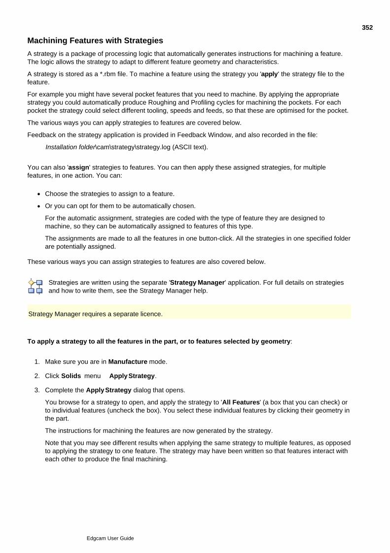
Machining Features with Strategies
A strategy is a package of processing logic that automatically generates instructions for machining a feature.The logic allows the strategy to adapt to different feature geometry and characteristics.
A strategy is stored as a *.rbm file. To machine a feature using the strategy you 'apply' the strategy file to thefeature.
For example you might have several pocket features that you need to machine. By applying the appropriatestrategy you could automatically produce Roughing and Profiling cycles for machining the pockets. For eachpocket the strategy could select different tooling, speeds and feeds, so that these are optimised for the pocket.
The various ways you can apply strategies to features are covered below.
Feedback on the strategy application is provided in Feedback Window, and also recorded in the file:
Installation folder\cam\strategy\strategy.log (ASCII text).
You can also 'assign' strategies to features. You can then apply these assigned strategies, for multiplefeatures, in one action. You can:
Choose the strategies to assign to a feature.
Or you can opt for them to be automatically chosen.
For the automatic assignment, strategies are coded with the type of feature they are designed tomachine, so they can be automatically assigned to features of this type.
The assignments are made to all the features in one button-click. All the strategies in one specified folderare potentially assigned.
These various ways you can assign strategies to features are also covered below.
Strategies are written using the separate 'Strategy Manager' application. For full details on strategiesand how to write them, see the Strategy Manager help.
Strategy Manager requires a separate licence.
To apply a strategy to all the features in the part, or to features selected by geometry:
Make sure you are in Manufacture mode.1.
Click Solids menu Apply Strategy.2.
Complete the Apply Strategy dialog that opens.
You browse for a strategy to open, and apply the strategy to 'All Features' (a box that you can check) orto individual features (uncheck the box). You select these individual features by clicking their geometry inthe part.
The instructions for machining the features are now generated by the strategy.
Note that you may see different results when applying the same strategy to multiple features, as opposedto applying the strategy to one feature. The strategy may have been written so that features interact witheach other to produce the final machining.
3.
1.
352
Edgcam User Guide
To apply strategies to selected features:
Make sure you are in Manufacture mode.1.
In the Features Window, click the required features to select them. You can use multiple-selectiontechniques - Ctrl-Click on a series of features for example.
2.
Right-click on any selected feature and from the shortcut menu select Apply Strategy.3.
In the Open dialog that starts, navigate to your saved strategy (.rbm file) and open this.
The instructions for machining the features are now generated by the strategies.
Note that you may see different results when applying the same strategy to multiple features, as opposedto applying the strategy to one feature. The strategy may have been written so that features interact witheach other to produce the final machining.
4.
To apply assigned strategies:
Once you have assigned strategies to features (see below), you can apply these strategies, for multiplefeatures, in one action:
Make sure you are in Manufacture mode. Start working in the Features Window.1.
To apply all the feature's strategies, select none of them. To apply only some of the features' strategies,click on these features to select them. You can use multiple selection techniques, for example Ctrl-Clickon a number of features.
2.
Click the Apply All Strategies button .
The instructions for machining the features are now generated by the strategies.
The order in which the strategies are applied to the features (and hence the ordering of the generatedinstructions in the sequence) is determined by the '#' Column in the Features Window - see the section'To change the machining order of the features' below.
Note that you may see different results when applying the same strategy to multiple features, as opposedto applying the strategy to one feature. The strategy may have been written so that features interact witheach other to produce the final machining.
The order in which the multiple strategies assigned to one feature are applied is in their listed order in theAssign Strategies to a Feature dialog (see below).
3.
To assign strategies to features manually:
In the Features Window click the required features to select them. You can use multiple selectiontechniques - Ctrl-Click on a series of features for example.
1.
Right-click on any selected strategy, and in the shortcut menu that opens click Assign Strategies.2.
In the Assign Strategies to a Feature dialog that opens:
Click the New button.a.
At the end of the new blank line click the button.b.
c.
d.
3.
353
Edgcam User Guide
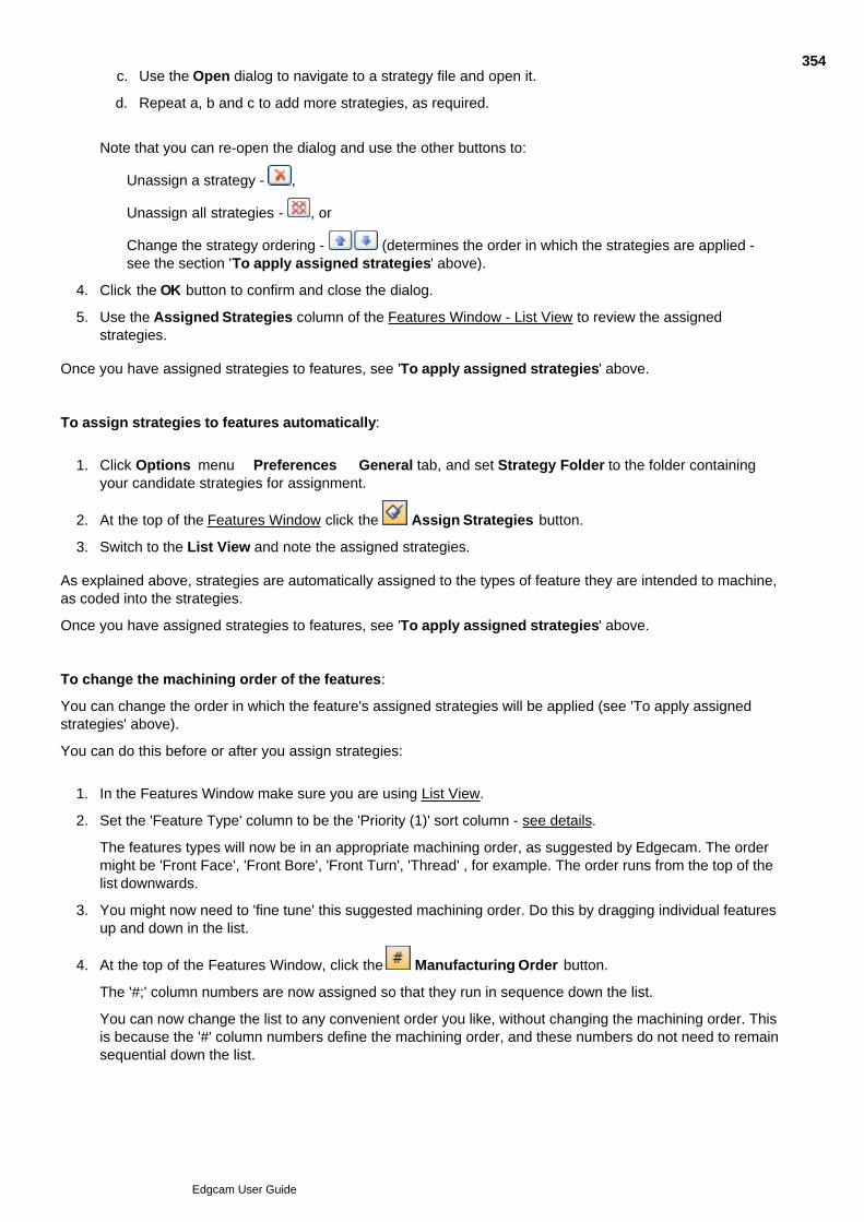
a.
b.
Use the Open dialog to navigate to a strategy file and open it.c.
Repeat a, b and c to add more strategies, as required.
d.
Note that you can re-open the dialog and use the other buttons to:
Unassign a strategy - ,
Unassign all strategies - , or
Change the strategy ordering - (determines the order in which the strategies are applied -see the section 'To apply assigned strategies' above).
Click the OK button to confirm and close the dialog.4.
Use the Assigned Strategies column of the Features Window - List View to review the assignedstrategies.
5.
Once you have assigned strategies to features, see 'To apply assigned strategies' above.
To assign strategies to features automatically:
Click Options menu Preferences General tab, and set Strategy Folder to the folder containingyour candidate strategies for assignment.
1.
At the top of the Features Window click the Assign Strategies button.2.
Switch to the List View and note the assigned strategies.3.
As explained above, strategies are automatically assigned to the types of feature they are intended to machine,as coded into the strategies.
Once you have assigned strategies to features, see 'To apply assigned strategies' above.
To change the machining order of the features:
You can change the order in which the feature's assigned strategies will be applied (see 'To apply assignedstrategies' above).
You can do this before or after you assign strategies:
In the Features Window make sure you are using List View.1.
Set the 'Feature Type' column to be the 'Priority (1)' sort column - see details.
The features types will now be in an appropriate machining order, as suggested by Edgecam. The ordermight be 'Front Face', 'Front Bore', 'Front Turn', 'Thread' , for example. The order runs from the top of thelist downwards.
2.
You might now need to 'fine tune' this suggested machining order. Do this by dragging individual featuresup and down in the list.
3.
At the top of the Features Window, click the Manufacturing Order button.
The '#;' column numbers are now assigned so that they run in sequence down the list.
You can now change the list to any convenient order you like, without changing the machining order. Thisis because the '#' column numbers define the machining order, and these numbers do not need to remainsequential down the list.
4.
5.
354
Edgcam User Guide

If you do want to change the machining order, you can use the button again and re-assign the '#' columnto the current list order. The '#' numbers will be re-set to the current list order, whether you have manuallyordered this, or automatically sorted on any column.
5.355
Edgcam User Guide
Launching Edgecam from CAD
Some CAD systems (see below) feature an Export to Edgecam button.
Clicking this button saves the CAD model to disk, then loads the model into Edgecam.
(Note that you are only prompted for a file name for models that are not yet saved, otherwise the save isautomatic.)
This method can transfer more data from the model to Edgecam, such as hole threading data and CPL data.(This information is transferred via a separate XML file, and is not available from the saved model file.)
Reloading
After making changes to the model in the CAD system, you can bring Edgecam up to date by re-using theExport to Edgecam button with the model still open in Edgecam. Again this transfers more data, via the XMLfile, over and above the other reload methods.
Using the launch option without Edgecam installed
You might want to distribute solid files for later use in Edgecam from a machine that does not itself haveEdgecam installed.
In this case you can still use the Export to Edgecam button - just make sure you distribute the saved XML file,along with the CAD model file. If these two files are copied into the same folder, Edgecam will read the extrainformation from the XML file when you open the solid file.
The XML file has the same name as the CAD model file, with '.XML' appended.
Note that this does not apply to the Edgecam Part Modeler CAD package, which does not save an XML file.
Installing the launch option
You can install the launch option using the Edgecam installation DVD (when installing Edgecam orsubsequently).
Alternatively you can download the installer from www.edgecam.com. (The Web site may be more up to dateand support additional systems over the DVD.)
You are individually prompted for installing into the CAD systems found on your PC.
These systems are supported:
·Edgecam Part Modeler* · SolidWorks
· Autodesk Inventor · Solid Edge
*In Edgecam Part Modeler the option is standard; no installation is needed.
For an up to date list of supported CAD system versions, see the What's New help.
See also
Transfer of CAD System Data to Edgecam
Importing CAD Thread Data
356
Edgcam User Guide
Transfer of CAD System Data to Edgecam
Over a CAD link there are options for importing:
Coordinate System Planes - SolidWorks and Solid Edge only.
Work Planes - see below.
Sketch Planes - Edgecam generates CPLs normal to these sketch planes.
Note that this data is transferred via an XML file created in the same folder as the CAD model (except fromEdgecam Part Modeler). The information is in addition to 'standard' information such as thread data.
The options are in Options menu Preferences dialog Solids tab. For more details click the dialog's Helpbutton, or click here.
CPLs from Work Planes
Edgecam CPLs from Work Planes are not associative to the CAD model, so if a work plane changes in theCAD system a new Edgecam CPL is generated; the original CPL is not modified.
Where possible, Edgecam will use the same identification names as the CAD system. However these aretruncated to 20 characters so we recommend you use names shorter than this.
If a CPL name already exists a new name is generated with a .1, .2 etc suffix.
Edgecam CPL names are optionally prefixed with 'WP_' or 'SP_'. This groups the CPLs in the listing for easyidentification.
357
Edgcam User Guide

Loading Solids Files
You open solids files in the same way as any other type of file.
Most popular solids file types are supported. For the latest versions supported see the What's New help. Forthe licenses required see Solid CAD Systems and Edgecam Licenses.
Pro/DESKTOP files (*.des) are listed under the Pro/ENGINEER file type.
Note:
As an alternative to opening a saved file, you can open a solid from some CAD packages directly; seeLaunching Edgecam from CAD for details.
There are options for the loading of solids; use Options menu Preferences Solids tab. For moredetails click the dialog's help button, or click here.
SolidWorks assemblies can only be opened directly from SolidWorks.
Before loading a SolidWorks file into Edgecam, if it contains configurations we recommend that you firstrebuild all the configurations. To do this there is a script you can run in SolidWorks:
Edgecam Installation Folder\Cam\Examples\solid machinist\solidworks\Scripts\ForceRebuild.swp
The solid model will be loaded into Edgecam using the current layer, colour and font for the solid. Whenloading parasolid files (*.x_t, *.x_b) colour properties for hole features will also be passed to Edgecam. Ifpreferred, these can be suppressed using the Face Colour - Ignore Model Values option on the Solids tab ofthe Preferences (Options menu) dialog. In addition, Edgecam allows you to colour the faces of a solid model bytheir geometry type. To enable this functionality, check the Face Colour - Render by Geometry Type option onthe Solids tab of the Preferences (Options menu) dialog. See Specifying Colour Preferences for Solid Models.
The load operation will automatically scale the solid to the current Edgecam units.
See Also
Solid Machinist Error Messages
Colour Preferences for Solid Models
Associative Reloading of Solid Models
Inserting a Solid Model
358
Edgcam User Guide
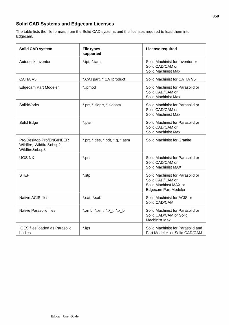
Solid CAD Systems and Edgecam Licenses
The table lists the file formats from the Solid CAD systems and the licenses required to load them intoEdgecam.
Solid CAD system File typessupported
License required
Autodesk Inventor *.ipt, *.iam Solid Machinist for Inventor orSolid CAD/CAM orSolid Machinist Max
CATIA V5 *.CATpart, *.CATproduct Solid Machinist for CATIA V5
Edgecam Part Modeler *..pmod Solid Machinist for Parasolid orSolid CAD/CAM orSolid Machinist Max
SolidWorks *.prt, *.sldprt, *.sldasm Solid Machinist for Parasolid orSolid CAD/CAM orSolid Machinist Max
Solid Edge *.par Solid Machinist for Parasolid orSolid CAD/CAM orSolid Machinist Max
Pro/Desktop Pro/ENGINEERWildfire, Wildfire 2,Wildfire 3
*.prt, *.des, *.pdt, *.g, *.asm Solid Machinist for Granite
UGS NX *.prt Solid Machinist for Parasolid orSolid CAD/CAM orSolid Machinist MAX
STEP *.stp Solid Machinist for Parasolid orSolid CAD/CAM orSolid Machinst MAX orEdgecam Part Modeler
Native ACIS files *.sat, *.sab Solid Machinist for ACIS orSolid CAD/CAM
Native Parasolid files *.xmb, *.xmt, *.x_t, *.x_b Solid Machinist for Parasolid orSolid CAD/CAM or SolidMachinist Max
IGES files loaded as Parasolidbodies
*.igs Solid Machinist for Parasolid andPart Modeler or Solid CAD/CAM
359
Edgcam User Guide

Notes on Loading Autodesk Inventor files
Required Software
To load an Autodesk Inventor file into Edgecam, one of the following products must be installed on the samePC:
Autodesk Inventor, or
Inventor View - a free utility that can be installed from the 'Autodesk Inventor View R11 - English' folder ofthe Edgecam DVD, or from the Autodesk Inventor CD. (This utility was formerly known as 'DesignTracking'.)
If neither product is installed, you see an error message on attempting to load an Autodesk Inventor file intoEdgecam.
Deleting temporary files Edgecam creates temporary copies of .ipt files in the cam\temp directory called iptsaved0.ipt and iptload0.ipt.Edgecam should automatically delete these files when loading a new part. If temporary .ipt files exist the wrongInventor file can be saved in the Edgecam part file (*.ppf). If this occurs you should delete the temporary files.
Reloading Inventor files
When reloading Autodesk Inventor parts up to, but not including, Inventor 4 features tend to be updated on abest match basis even when the solid model has not been modified. We recommend updating the parts to alater version of Inventor to overcome this problem.
Also see: Launching Edgecam from CADNotes on Loading Autodesk Inventor Assemblies
360
Edgcam User Guide

Notes on Autodesk Inventor Assemblies
Inventor 9 SP1 and above only
Inventor Assemblies use Project files to define the component locations. Ensure the Inventor or Inventor Viewhas the correct Project selected before loading the assembly; otherwise some or all components may not beloaded.
When moving or copying an assembly from its original location toanother PC drive, CD-ROM or Network location the Inventor Packand Go utility must be used so that the Project paths are correctlyupdated. To use the Pack and Go feature right mouse click on theassembly file (*.iam) and select Pack and Go. Please read the Helpavailable with this utility for further information.
You can:
Use File Open to open a saved Inventor Assembly (*.iam) file into Edgecam.
Or use the 'launch Edgecam' option within Autodesk Inventor, with the assembly open. Using the 'launchEdgecam' option can transfer more information, such as threading data, work planes, sketch planes andco-ordinate system planes.
Please note:
This information on loading thread data.
If the assembly is modified and saved, then Edgecam knows to reload the assembly.
If a component part is reloaded into the assembly, then Edgecam knows to reload the new assemblyonce it has been saved.
If a component part is modified,then Edgecam will NOT know to reload it until the assembly has beenupdated and saved.
If parts are transformed in the (Inventor) assembly, Edgecam knows to reload the updated assemblyitself.
The assembly can be transformed in Edgecam.
Separate parts cannot be moved individually in Edgecam.
Associativity in Edgecam is OK if parts are transformed in the (Edgecam) assembly.
Associativity in Edgecam is OK if an individual part is changed inside or outside of the assembly.
Associativity in Edgecam is NOT OK if parts are removed or added to the assembly.
See also:
Notes on Loading Autodesk Inventor files.
361
Edgcam User Guide
Notes on Loading Granite Models
Accuracy of Granite models
See Solid CAD Systems and Edgecam Licenses for a summary of the Granite CAD systems and file types.
To ensure that Granite models are machined to the required accuracy in Edgecam you should ensure that themodel is created in the CAD system to at least the desired machining tolerance. (Note that in a Pro/Engineermodel this is the Absolute tolerance - see more details.).
Alternatively you can set your preferred Granite model tolerance using Options menu Preferences Solids tab Granite Model Tolerance (inch/mm); if necessary models are converted to this tolerance onbeing loaded (or automatically re-loaded).
You can check the tolerance when you load or transform the solid, as the internal tolerance is displayed in theFeedback Window. (Unless this is disabled; to enable it use Options menu Preferences Solids tab, andclick the unchecked Model Tolerance Notification checkbox.)
You can also find out the internal tolerance by using Verify menu Entity and selecting (digitising) the solid.
If you create a cycle based on solid geometry with a tolerance tighter than the internal tolerance of the solid,you see a Feedback Window message; for example:
CAD kernel data may be out of tolerance
Solid model internal tolerance: 0.018720896
is looser than required tolerance: 0.01
The cycle will still generate successfully however.
Loading of PDT files
We do not recommend using PDT files if you have the DES or PRT file available (or a means to createthem).
PDT files are designed as an internal transfer mechanism between PTC products; exporting them intothird party products is not recommended.
PDT files have a hard coded internal tolerance that is far tighter than the default tolerance of either PRTor DES files used to create them.
If you experience problems when performing a Feature Find command on a PDT file, adjusting thesystem tolerance in Edgecam may resolve the problem.
362
Edgcam User Guide

Notes on Loading SolidWorks Parts
Although SolidWorks parts can have multiple configurations, the part is saved with the original solid definitionirrespective of the active configuration at the time. This is then loaded when you open in Edgecam (that is theParasolid in the .sldprt file).
If you want to load a specific configuration:
Select the configuration required in SolidWorks1.
Output an .x_t file.2.
Load the .x_t file into Edgecam.3.
Alternatively, use the 'Launch Edgecam' option within SolidWorks, as described below.
SolidWorks Configurations
When launching a SolidWorks file with configurations, you can now restrict this to only loading the activeconfiguration instead of all configurations, using the Active Configuration option on the Solids tab on thePreferences (Options menu) dialog. When loading a .sldprt file, the configuration that was active when thepart was saved will be loaded.
Please note that each configuration (including the default) needs to be saved in SolidWorks, if it is to beloaded into Edgecam.
Colour Support
For SolidWorks 2006 SP1 and later, using the 'Launch Edgecam' loads colour data into Edgecam.
363
Edgcam User Guide

Notes on Loading SolidWorks Assemblies
SolidWorks 2003 and above only
To load a SolidWorks assembly into Edgecam.
In SolidWorks, first save. Then with the assembly still open use the launch Edgecam button.
For Edgecam use, workplane and other data is now written out to a separate .XML file. This is createdwith the same name as the assembly (but with a '.XML' extension), in the same folder.
Edgecam now starts and searches for the assembly structure file. If this is missing or out of date, you areprompted to repeat the launch from SolidWorks.
The assembly is then loaded as one BREP, which is associative to the assembly filename. (The BREPmay contain multiple solid bodies.) The data in the .xml file is also loaded.
Individual bodies may be machined and searched for features, but all the bodies will be transformedor deleted together.
Note that even if your CAD machine does not have Edgecam installed you can still install and use the launchEdgecam facility. You just need to make sure that the saved solid file and XML file are distributed together, andkept in the same folder. Open the solid file into Edgecam from the new folder and the XML data will also beread.
Assemblies, layers and configurations
When loading solid assemblies you can specify whether all parts are placed on the same layer or each part isplaced on an individual layer using the Separate Layers option on the Solids tab of the Preferences (Optionsmenu) command. The default setting for this option is OFF.
When checked, each part is placed on a separate layer where the layer name is the name of the assembly filefollowed by the part number, i.e. filename - 001, filename - 002 etc. That is unless the part containsconfigurations, when the configuration names are used.
If the option is unchecked, all parts will be placed onto the current layer.
Summary of functionality
If a changed part is reloaded into the assembly, then Edgecam knows to reload the new assembly
If parts are transformed in the (SolidWorks) assembly, Edgecam knows to reload the updated assembly.
The assembly can be transformed in Edgecam.
Separate parts cannot be moved individually in Edgecam.
Associativity in Edgecam is OK if parts are transformed in the (Edgecam) assembly.
Associativity in Edgecam is OK if an individual part is changed inside or outside of the assembly.
Associativity in Edgecam is not OK if parts are removed or added to the assembly.
To maintain associativity, you will need to re-launch Edgecam from SolidWorks using the Edgecam launchbutton and with the Edgecam session open, this will update the data in the file containing the assemblystructure.
364
Edgcam User Guide

Notes on Loading Pro/ENGINEER Assemblies
Once loaded or inserted, the assembly file is not associative, that is if parts are added to or removed from theassembly the Edgecam .ppf file will not be updated. Any changes made at assembly level in Pro/ENGINEERwill not be detected unless they affect the parts. Changes at part level will be detected and Edgecam willprompt for a re-load (if the Change Notification option on the Preferences dialog is switched on).
Assembly cuts are only supported if they intersect at part level.
Empty parts (for bill of material purposes etc.) and surface only parts are excluded, and the assembly file willcontinue to load any valid files until the end of the assembly file is reached. An error message will be displayed"Some files did not produce solid models:", followed by file path and part name.
Assemblies generated by Pro/Engineer manufacturing modules (i.e. Mold) are not supported.
Assemblies and layers
When loading solid assemblies you can specify whether all parts are placed on the same layer or each part isplaced on an individual layer using the Separate Layers option on the Solids tab of the Preferences (Optionsmenu) command. The default setting for this option is OFF.
When checked, each part is placed on a separate layer where the layer names are those of the individual partsloaded. When loading assemblies that contain multiples of the same solid part, all instances of the solid areplaced on a common layer.
If the option is unchecked, all parts will be placed onto the current layer.
Summary of functionality
Edgecam cannot detect if an assembly has changed as it references individual parts not the wholeassembly.
Separate parts of an assembly can be transformed in Edgecam individually or in groups.
Associativity in Edgecam is not OK if parts are transformed in the assembly.
Associativity in Edgecam is OK if an individual part is changed outside of the assembly.
Associativity in Edgecam is not OK if parts are removed or added to the assembly.
365
Edgcam User Guide

Notes on CATIA V5 Files
When opening CATIA V5 files (.CATpart and .CATproduct), please note:
A .CATproduct file is typically an assembly, referencing other files of type .CATpart and/or .CATproduct.These other files must also be present; the .CATproduct file on its own is unlikely to load successfully.
A CATIA V4 part referenced by a CATIA V5 part will not be loaded.
Non-manifold models are not supported.
Files with non-ASCII characters in their name or path cannot be loaded.
Note that there is also a loader for CATIA V4 files - see CATIA V4 Loader.
366
Edgcam User Guide
Notes on loaded non-assembly multiple-body files
Below are some notes relating to non-assembly multiple-body files loaded into Edgecam (these do not apply toassembly files, which have their own topics):
When feature finding, individual solids can be selected. Each body:
may have its own colour, font and layer.
may be machined separately.
may be digitised as stock or fixture separately.
Deleting one body in the Edgecam deletes all the other bodies from the same file. Deleting bodies may haveundesirable effects if digitised stock or fixtures are specified.
If you add a body to the model and update Edgecam, the new body in Edgecam will have the same colour andlayer as the first body.
When merging two or more bodies by Boolean union, the target part (the part that is to have others merged toit) will retain its features, the features of any tool part (part that is to be merged) will be automatically orphanedand deleted (even if the Delete Orphaned Features preference has not been checked). Any new featurescreated by the union on the target part will be displayed as “New” in the Features Window.
Bodies may be all on same layer, or on separate individual layers, depending on the setting of the 'SeparateLayers' Preferences option (Solids tab). If on separate layers, these are given the name of the solid filefollowed by the body number. If on one layer, this will be the active layer at the time of the load.
When using the transform commands (Rotate, Scale, Translate):
Pick a solid in a multiple body solid and all the solid bodies will be transformed.
Pick a stock feature and the solid bodies and stock will be transformed.
Pick a fixture and the solid bodies and fixture will be transformed.
Pick all (ctrl+'A') and all the solid bodies, stocks and fixtures will be transformed.
367
Edgcam User Guide

Notes on UGS NX Files
These items are not supported:
Surface bodies.
Colours.
Assembly (reference files).
Drawings.
Information such as thread data, hole data, CPLs and so on.
368
Edgcam User Guide

Inserting a Solid Model
Requires Edgecam Solid Machinist licence
A solid model may be added or inserted to an existing worksession using the File Insert, Solid (File Menu)command. This allows you to scale, rotate and translate the model.
The inserted model uses the current colour and font for the solid model but you can override the model's colourand substitute a colour of your own choice.
The model will be inserted on the current layer for the solid model unless a different layer is specified.
Multiple models may be inserted each with different transformations if required.
Inserting an Edgecam part file that contains a solid model
You can also insert an Edgecam part file (*.ppf) that contains a solid model as a part or component. This allowsyou to scale, rotate and translate the model. Multiple models may be inserted each with differenttransformations if required.
369
Edgcam User Guide

Saving Parts
If an Edgecam worksession contains a solid model, the Save command will write the model to the Edgecampart file (*.ppf). You can then reload this part file in a subsequent worksession. If a part file containing a solidmodel is loaded and the Solid Machinist licence is not available, the solid portion of the model will be ignoredand will not be loaded or displayed.
370
Edgcam User Guide
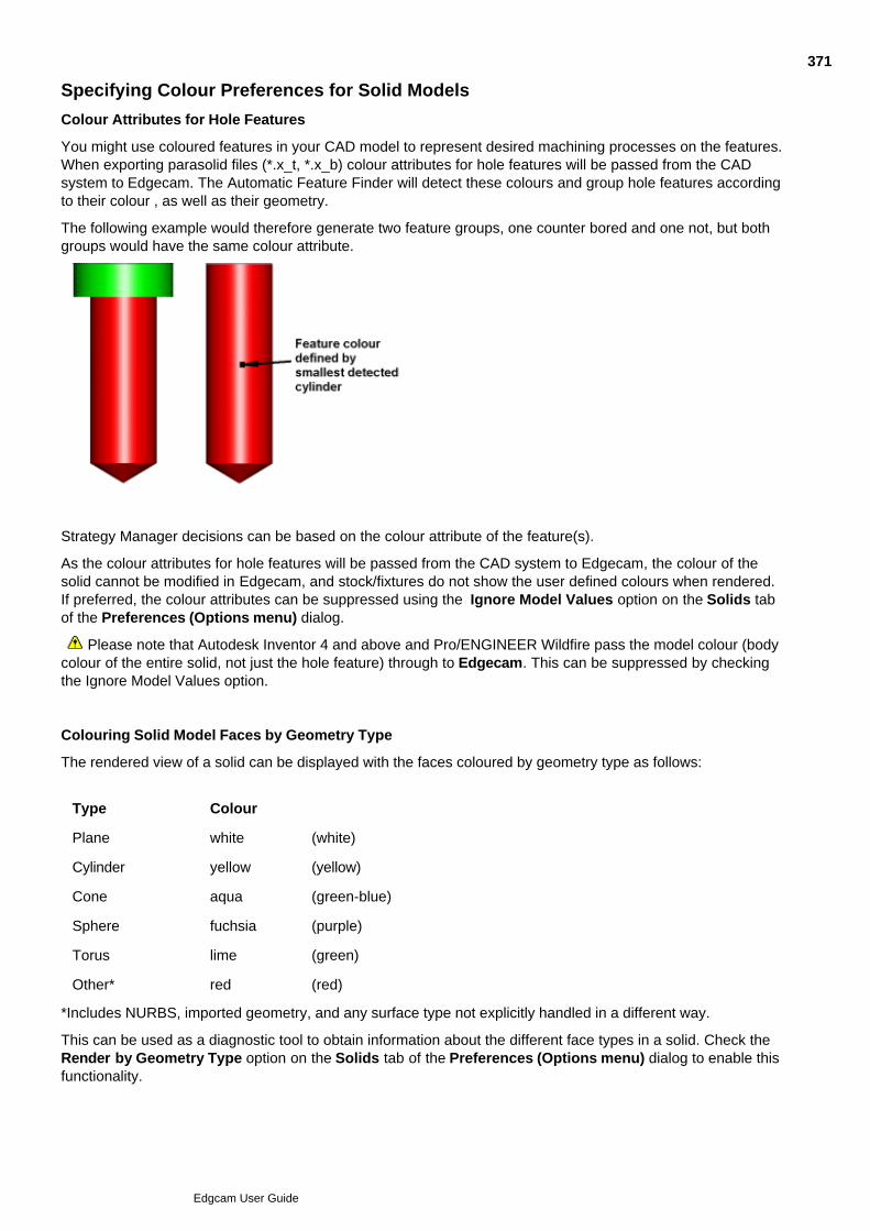
Specifying Colour Preferences for Solid Models
Colour Attributes for Hole Features
You might use coloured features in your CAD model to represent desired machining processes on the features.When exporting parasolid files (*.x_t, *.x_b) colour attributes for hole features will be passed from the CADsystem to Edgecam. The Automatic Feature Finder will detect these colours and group hole features accordingto their colour , as well as their geometry.
The following example would therefore generate two feature groups, one counter bored and one not, but bothgroups would have the same colour attribute.
Strategy Manager decisions can be based on the colour attribute of the feature(s).
As the colour attributes for hole features will be passed from the CAD system to Edgecam, the colour of thesolid cannot be modified in Edgecam, and stock/fixtures do not show the user defined colours when rendered.If preferred, the colour attributes can be suppressed using the Ignore Model Values option on the Solids tabof the Preferences (Options menu) dialog.
Please note that Autodesk Inventor 4 and above and Pro/ENGINEER Wildfire pass the model colour (bodycolour of the entire solid, not just the hole feature) through to Edgecam. This can be suppressed by checkingthe Ignore Model Values option.
Colouring Solid Model Faces by Geometry Type
The rendered view of a solid can be displayed with the faces coloured by geometry type as follows:
Type Colour
Plane white (white)
Cylinder yellow (yellow)
Cone aqua (green-blue)
Sphere fuchsia (purple)
Torus lime (green)
Other* red (red)
*Includes NURBS, imported geometry, and any surface type not explicitly handled in a different way.
This can be used as a diagnostic tool to obtain information about the different face types in a solid. Check theRender by Geometry Type option on the Solids tab of the Preferences (Options menu) dialog to enable thisfunctionality.
371
Edgcam User Guide
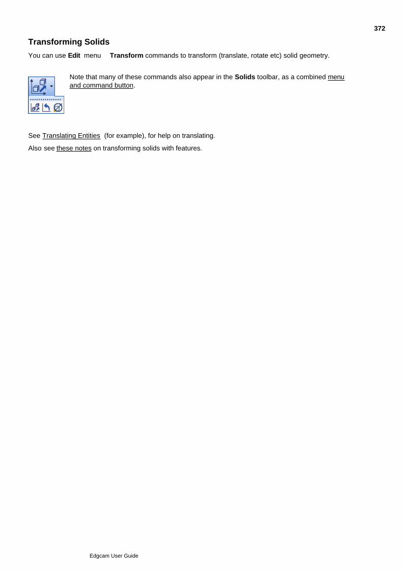
Transforming Solids
You can use Edit menu Transform commands to transform (translate, rotate etc) solid geometry.
Note that many of these commands also appear in the Solids toolbar, as a combined menuand command button.
See Translating Entities (for example), for help on translating.
Also see these notes on transforming solids with features.
372
Edgcam User Guide

Solids Preferences
Use Options menu Preferences Solids tab to make preferences settings relating to solids.
(You can also access this help using the cycle dialog's Help button.)
373
Edgcam User Guide

Feature-Based Instruction Validity Checking
You can check a feature to make sure that any cycles and operations based on the feature are still valid.
(Note that there can also be automatic checks for missing geometry).
Make sure you are in Manufacture mode.1.
Click the Instructions menu and click the Feature Check command.
Alternatively click the command's button in the Edit toolbar:
2.
Pick the features you want to check by digitising them in the Graphics area, or clicking them in theFeatures window. Alternatively just finish the command to check all the features.
You see feedback on the checking in the Feedback window, and any invalid sequences are marked inthe Sequence window.
3.
374
Edgcam User Guide
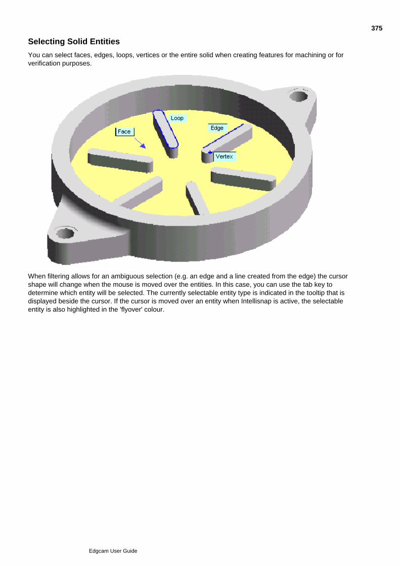
Selecting Solid Entities
You can select faces, edges, loops, vertices or the entire solid when creating features for machining or forverification purposes.
When filtering allows for an ambiguous selection (e.g. an edge and a line created from the edge) the cursorshape will change when the mouse is moved over the entities. In this case, you can use the tab key todetermine which entity will be selected. The currently selectable entity type is indicated in the tooltip that isdisplayed beside the cursor. If the cursor is moved over an entity when Intellisnap is active, the selectableentity is also highlighted in the 'flyover' colour.
375
Edgcam User Guide
Features in Solid Machinist
Features are inherent in the way solids are constructed. For example a solid body, or part of a solid body, mighthave been created by extruding a profile in a 'Boss procedure' .
You create Edgecam features by identifying the geometry in the solid (bosses, pockets and so on) that you aregoing to use in your machining, and the Edgecam features (bosses, pockets and so on) are created to matchthis geometry.
Features are not rigidly locked to the geometry. They have properties you can edit, such as level and depth,which may mean the feature no longer matches the solid geometry. However the features are 'associative', soon reloading the solid, the features automatically adapt themselves to match the new geometry, and/or youredits to the features may be lost.
You can work with features (delete them or edit them to change their colour, for example), in the FeaturesWindow. You can view the properties of features in the Properties Window.
Features have properties which can be passed through to the cycle when you machine them. For example bychecking 'Associative' in the cycle dialog, the cycle can automatically use the Level and Depth properties offeatures.
Features and CPLs
Features are found in CPLs. For a boss feature to be found (for example) the plane of the top face must beparallel to the selected CPL (it must also be planar).
In the Features Tree, features appear inside a branch for their CPL. (You can select multiple CPLs to findfeatures in all of them at once).
To machine a feature you must index to its CPL.
Machining features
You always machine features in basically the same way. In cycles you set the 'Model Type' option in the dialogto 'Solid'. You then go on to digitise the feature, when selecting the cycle's geometry. To use an operation youcan right-click on the option in the Features window and select from the shortcut menu.
Creating features
You can create features:
Automatically, using the Feature Finder command. You can specify a colour and/or layer for features onthe Display tab of the Feature Finder dialog.
Or manually (by digitising), using a variety of commands (see Feature Types for details of the commandsand the feature types they can find). Features are displayed in the colour, and on the layer, displayed onthe Standard toolbar.
Displaying Features
To display features (in translucent form) click Toggle Features in the Display toolbar to activate it.Click Toggle Features again to de-activate it and switch off the feature display
Browsing and Editing Features
You can browse and edit features in the Features Window, in combination with the Properties Window.
Not all properties can be edited, and some properties can only be edited in the edit dialog (double click on afeature in the Features Window, or right-click on the feature and from the shortcut menu select Edit).
Note that on re-loading a model, feature edits are liable to be lost as the feature re-synchronises itself with the
376
Edgcam User Guide
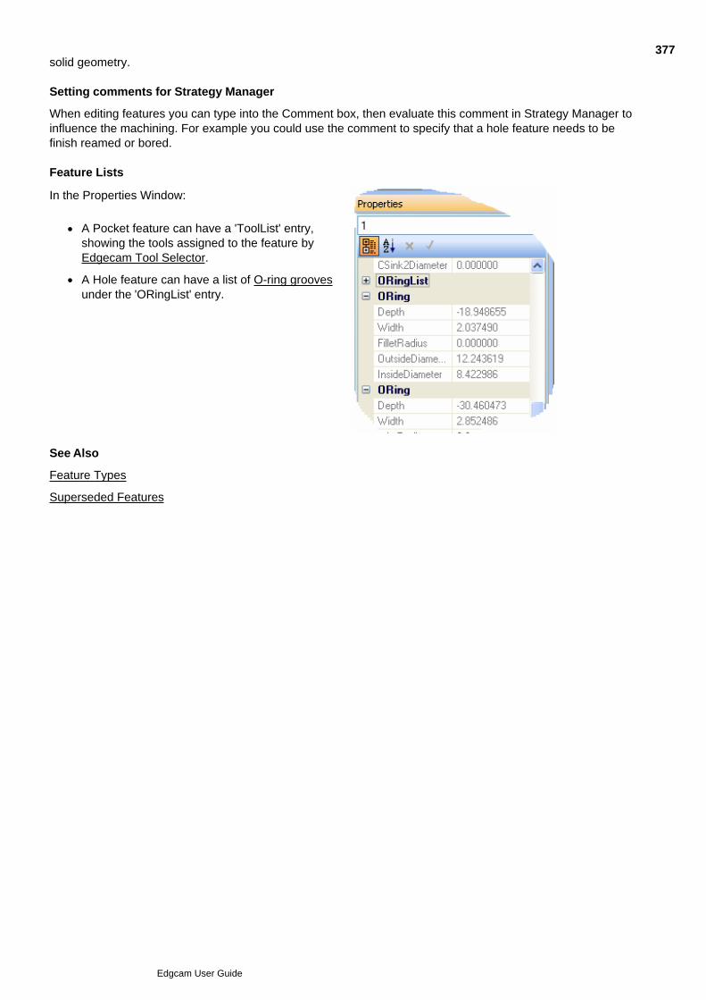
solid geometry.
Setting comments for Strategy Manager
When editing features you can type into the Comment box, then evaluate this comment in Strategy Manager toinfluence the machining. For example you could use the comment to specify that a hole feature needs to befinish reamed or bored.
Feature Lists
In the Properties Window:
A Pocket feature can have a 'ToolList' entry,showing the tools assigned to the feature byEdgecam Tool Selector.
A Hole feature can have a list of O-ring groovesunder the 'ORingList' entry.
See Also
Feature Types
Superseded Features
377
Edgcam User Guide

Automatically Finding Features using Feature Finder
Use Solids menu Feature Finder to automatically find features (pockets, holes, bosses andturn profiles) on the solid body, using the Feature Finder dialog.
Here is the help on the Feature Finder dialog (you can also access this help by clicking the Help button in thedialog):
378
Edgcam User Guide
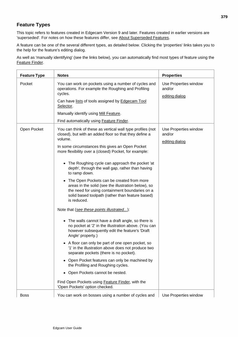
Feature Types
This topic refers to features created in Edgecam Version 9 and later. Features created in earlier versions are'superseded'. For notes on how these features differ, see About Superseded Features.
A feature can be one of the several different types, as detailed below. Clicking the 'properties' links takes you tothe help for the feature's editing dialog.
As well as 'manually identifying' (see the links below), you can automatically find most types of feature using theFeature Finder.
Feature Type Notes Properties
Pocket You can work on pockets using a number of cycles andoperations. For example the Roughing and Profilingcycles.
Can have lists of tools assigned by Edgecam ToolSelector.
Manually identify using Mill Feature.
Find automatically using Feature Finder.
Use Properties windowand/or
editing dialog
Open Pocket You can think of these as vertical wall type profiles (notclosed), but with an added floor so that they define avolume.
In some circumstances this gives an Open Pocketmore flexibility over a (closed) Pocket, for example:
The Roughing cycle can approach the pocket 'atdepth', through the wall gap, rather than havingto ramp down.
The Open Pockets can be created from moreareas in the solid (see the illustration below), sothe need for using containment boundaries on asolid based toolpath (rather than feature based)is reduced.
Note that (see these points illustrated...):
The walls cannot have a draft angle, so there isno pocket at '2' in the illustration above. (You canhowever subsequently edit the feature's 'DraftAngle' property.)
A floor can only be part of one open pocket, so'1' in the illustration above does not produce twoseparate pockets (there is no pocket).
Open Pocket features can only be machined bythe Profiling and Roughing cycles.
Open Pockets cannot be nested.
Find Open Pockets using Feature Finder, with the'Open Pockets' option checked.
Use Properties windowand/or
editing dialog
Boss You can work on bosses using a number of cycles and Use Properties window
379
Edgcam User Guide
operations. For example the Roughing and Profilingcycles.
Manually identify using Mill Feature.
Find automatically using Feature Finder.
and/or
editing dialog
Profile A profile is typically a vertical sheet (has level anddepth), that can be machined using the Profiling cycle.
A profile has a 'material' side, and you can onlymachine along the opposite side to this (you can editthe Profile to reverse the material side).
Manually identify using Mill Feature (only)
Use Properties windowand/or
editing dialog (same editdialog as pockets/bosses)
Hole Can be machined by the Hole Cycle (not supersededversion), Roughing and Profiling cycles. Can havecomplex wall shapes. Can be radial.
Can be identified by the Type property of FT_HOLE2.
Can have lists of O-ring grooves.
Manually identify using Hole Feature. Use this methodif you need more control over the feature creation.
Can have 'custom properties' for use by strategies.
Find automatically using Feature Finder.
Use Properties windowand/or
editing dialog
Face A face feature is a flat surface derived from a flat faceof the solid.
You can machine a face feature using the ParallelLace cycle, or Five Axis Milling cycle, for example.
Face Features are lost if their geometry in the solid isdeleted (unlike other types of feature which can stillexist as 'orphaned', if their geometry is deleted).
Manually identify using Face Feature (only).
Use Properties windowand/or
editing dialog
Edge Loop These can be used as containment boundaries incycles and operations (loops only), and in 4/5 AxisSimultaneous Milling as drive curves (for example).
Edge Loop Features are useful if you want to maintainassociativity with the solid model - when used as acontainment boundary instead of a wireframe boundaryfor example.
Unlike other types of feature, these can be '3D', so theedge loops you digitise need not lie in a flat horizontalplane (that is in the XY plane of the CPL).
Manually identify using Edge Loop Feature (only).
This type only has 'style'type properties, such asthe Layer and Colour.
Turn Features These represent profiles you can use in Turning.
There are several Turn feature sub-types, including'Front Turn' and 'Back Turn'. These are created to bemachineable by the various different tools and toolorientations. See illustrations...
Find automatically using Feature Finder (Turn tab).
Properties include 'Spindle'(useful for features copiedto the sub-spindle - seedetails) and CPL.
Use the PropertiesWindow.
380
Edgcam User Guide

Manually identify using Turn Feature
Note there is also a set of superseded Turn features(pre-Version 12.50). These are compatible in terms oftheir machining cycle support, but are more limited infunctionality and properties.
381
Edgcam User Guide
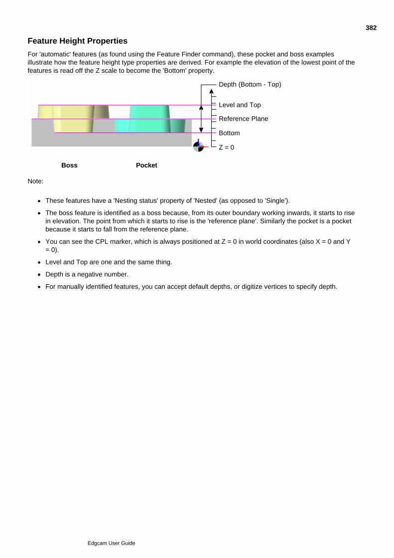
Feature Height Properties
For 'automatic' features (as found using the Feature Finder command), these pocket and boss examplesillustrate how the feature height type properties are derived. For example the elevation of the lowest point of thefeatures is read off the Z scale to become the 'Bottom' property.
Depth (Bottom - Top)
Level and Top
Reference Plane
Bottom
Z = 0
Boss Pocket
Note:
These features have a 'Nesting status' property of 'Nested' (as opposed to 'Single').
The boss feature is identified as a boss because, from its outer boundary working inwards, it starts to risein elevation. The point from which it starts to rise is the 'reference plane'. Similarly the pocket is a pocketbecause it starts to fall from the reference plane.
You can see the CPL marker, which is always positioned at Z = 0 in world coordinates (also X = 0 and Y= 0).
Level and Top are one and the same thing.
Depth is a negative number.
For manually identified features, you can accept default depths, or digitize vertices to specify depth.
382
Edgcam User Guide

Face Features - Overview
If you only want to machine one face of the solid you can turn it into a 'face feature', and digitise this as thegeometry for a cycle (instead of digitising the complete solid). Face features have their own separate identity;they appear in the Features Window, for example.
You create a face feature from a face using Face Feature in the Solids Menu to open the Face Featuredialog.
Note that:
You can group several faces together into one face feature.
A face can be a member of different face features.
Face features are associative to the model.
Face features record which side the material is on, so the correct side is automatically machined incycles.
In the dialog you can make settings that automatically group several related faces into one feature, to formgeometry for a SWARF Operation.
When a cycle or operation prompts you to specify a surface, you can digitise/select any combination of:
Edgecam surfaces,
surface groups (containing just Edgecam surfaces),
face features,
an entire solid body.
The cycle will only process the surfaces you have grouped together, this will prevent full gouge protection ofthe solid body.
383
Edgcam User Guide

Notification of Model Change
When working with an Edgecam part containing an embedded solid model, the system continuously checks thedate-time stamp of the solid model. When a difference is found a dialog is displayed asking if you wish toreload the model.
If the original design file is still open it is not possible to reload the model and a warning will be displayed.
384
Edgcam User Guide
Aligning the Body for Turning
Use Solids menu Align Body for Turning to re-align and position a solid body for turning.
(Note that you can also opt for the part to be automatically aligned on opening - check Optionsmenu Preferences Solids tab Auto align for turn. You need the ZX environment set as thedefault, as determined by the specified defaults file.)
The command prompts you to digitise faces to be used for the re-orientation.
Each digitise immediately results in the re-orientation, so you can work interactively.
Perform a finish (right-click for example) to move on to the next prompt.
Before the finish you can digitise again to change your selection.
Before the finish you can digitise the same face or edge to rotate the body (see below).
You can perform the finish without digitising if you want to skip a stage.
The prompts are:
Select face to define axis of rotation.
Click on a cylindrical face to be aligned with, and centred round, the Z axis. Click the face again if youwant to then invert the body (rotates 180° around the X Axis).
1.
Select face to define origin plane.
Click on the face that you want to be placed at the origin (centre of face placed at Z & X = 0).
2.
Select face to define C orientation.
Click on a face that you want to be normal to the X axis, rotating the part round Z. This will typically be aflat in a cylindrical face. Each subsequent click further rotates the body 90° round Z. As an alternative toa flat face, you can click one of the faces of a radial hole.
3.
385
Edgcam User Guide
Aligning the Body for Milling
Use Solids menu Align Body for Milling to rotate a solid body to a more convenient orientationrelative to the current CPL, and optionally move the body to a more convenient position within theCPL.
The command prompts you to digitise a face, edge and point, to be used for the re-orientation.
Each digitise immediately results in the re-orientation, so you can work interactively.
Perform a finish (right-click for example) to move on to the next prompt.
Before the finish you can digitise again to change your selection.
Before the finish you can digitise the same face or edge to rotate the body (see below).
You can perform the finish without digitising if you want to skip a stage.
The prompts are:
Select Face to Define XY plane.
Click on a face to provide a vector to be aligned with the CPL's Z Axis (face normal vector for planarfaces, face axis for cylindrical, conical or toroidal faces). Click the face again if you want to then invert thebody (rotates 180° around the Y Axis).
1.
Select linear edge to define CPL plane Axis.
Click on the edge that you want to be parallel with the CPL's X Axis. Click the edge again if you want torotate the body 90° around the CPL's Z Axis.
2.
Select point to translate to origin.
Click on the point you want to move to the CPL's origin.
Alternatively you can position the centre of the solid at the origin ('centre' meaning the centre point of abounding box round the solid). To do this hold down the Ctrl key and digitise the whole solid body, or anyof its faces.
Before finishing you can optionally adjust the height of the solid by pressing the Z key, clicking OK in thecoordinate dialog, then digitising a point to be placed at Z=0.
3.
386
Edgcam User Guide

Creating Hole Group Entities
Use Solids menu Group Holes to open the dialog below.
(You can also access this help using the cycle dialog's Help button.)
387
Edgcam User Guide
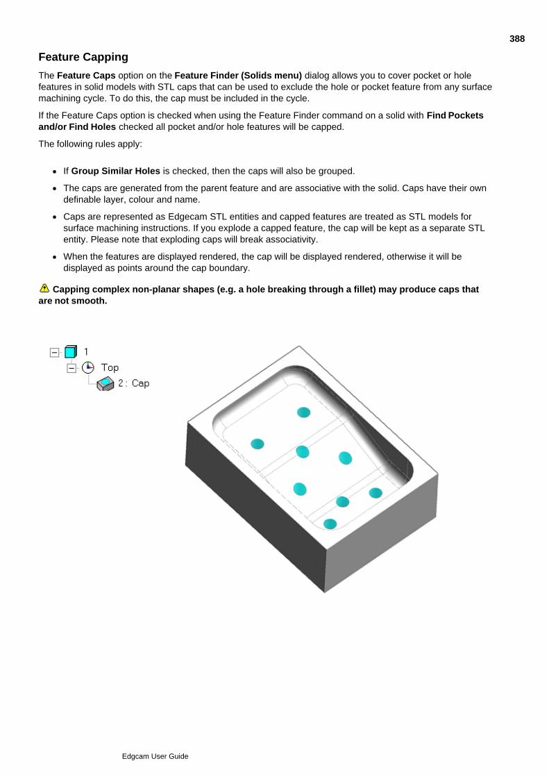
Feature Capping
The Feature Caps option on the Feature Finder (Solids menu) dialog allows you to cover pocket or holefeatures in solid models with STL caps that can be used to exclude the hole or pocket feature from any surfacemachining cycle. To do this, the cap must be included in the cycle.
If the Feature Caps option is checked when using the Feature Finder command on a solid with Find Pocketsand/or Find Holes checked all pocket and/or hole features will be capped.
The following rules apply:
If Group Similar Holes is checked, then the caps will also be grouped.
The caps are generated from the parent feature and are associative with the solid. Caps have their owndefinable layer, colour and name.
Caps are represented as Edgecam STL entities and capped features are treated as STL models forsurface machining instructions. If you explode a capped feature, the cap will be kept as a separate STLentity. Please note that exploding caps will break associativity.
When the features are displayed rendered, the cap will be displayed rendered, otherwise it will bedisplayed as points around the cap boundary.
Capping complex non-planar shapes (e.g. a hole breaking through a fillet) may produce caps thatare not smooth.
388
Edgcam User Guide

Depth in Manually Derived Features
When you are manually deriving a feature and you digitise an edge, loop or face, then the depth of the featureis set between the highest and lowest points on all the faces that neighbour this, as in this example based onprofiles from edges .
However you can change these; at the next step you are prompted to 'Digitise one or more vertices to specifydepth range (or return)'.
Edgecam guesses what point you are altering:
If you digitise near the highest point, you alter the highest point.
If you digitise near the lowest point, you alter the lowest point.
If you make two digitises, the depth is set between them.
389
Edgcam User Guide

Manual Feature Identification using Mill Feature
You can manually identify features using the Mill Featurecommand.
Depending on the chosen 'Strategy', you can identify Blind Pockets, Through Pockets, Bosses and Profiles.
Below are details on the Mill Feature dialog's settings (you can also access this help by clicking the Help buttonin the dialog):
Note that when digitising loops or combinations of edges, the feature will have a height set to the highest pointon the loop or edges. See also Digitise Vertex for Depth in Profile Features.
390
Edgcam User Guide
Manual Feature Identification using Edge Loop Feature
You can manually identify Edge Loop Features using Solids menu EdgeLoop Feature.
Here is the help for the Edge Loop Feature dialog (you can also access this help by clicking the Help button inthe dialog):
391
Edgcam User Guide

Using Face Feature
Use Solids menu Face Feature to open the dialog below.
(You can also access this help using the cycle dialog's Help button.)
392
Edgcam User Guide

Manual Feature Identification using Hole Feature
You can manually identify Hole Features using Solids menu Hole Feature.
Here are details on the Hole Feature dialog's settings (you can also access this help by clicking the Help buttonin the dialog):
393
Edgcam User Guide

Manual Feature Identification using Turn Feature
You can manually identify Turn Features using Solids menu Turn Feature.
Here are details on the Turn Feature dialog's settings (you can also access this help by clicking the Help buttonin the dialog):
394
Edgcam User Guide
Creating a CPL from a Solid Face
The command CPL (Solids menu) or the icon allows you to create a CPL from a Solid Face. Thisrequires the selection of a face, plus an origin (optional). You can select the origin from any points on themodel (including typed in co-ordinates and vertices). This CPL can then be used as a reference for machiningpurposes.
This function provides a method of CPL creation for Multi-plane applications. The full functionality for CPLcreation is available through the normal Create CPL command, although this will first require you to create theEdgecam geometry.
CPL creation from cylinders/cones
The Face Axis option (Plane modifier) allows you to select conical and cylindrical faces from a solid for CPLcreation, typically useful in the multiplane milling environment when creating a CPL which is normal to a hole.
The orientation is taken from the cylinder, the Z-axis of the CPL will point away from the middle of the cylinder.If the datum position for the CPL is above the center of the cylinder the CPL's Z axis will point up and if thedatum is below the center of the cylinder the Z axis will point down.
You will be prompted to pick the cylindrical face to define the CPL orientation.
You can intellisnap the origin at either end of the cylindrical face along the centreline of the cylinder. (Thisselection mode is optional and can be controlled by checking the appropriate box on the Selection tab of thePreferences (Options menu) dialog. The default setting for this option is ON.)
395
Edgcam User Guide
Solid Machinist Error Messages
There are a number of possible error messages you might see on loading or machining solids. The messagewill indicate a problem in one of the following areas:
Problems with file opening/loading
Check that:
The file is not corrupt.
The file type and version is supported. For the latest information see the What's New help.
You have the appropriate licence.
The file is not deleted or hidden, or that the security is not too tight.
Your Autodesk Inventor/VoloView/Design Tracking/Inventor View software is not too old.
The solid model or file is not locked by another application.
Problems with non-manifold geometry
Check that:
The model has no gaps between faces, leading to faces with no facets.
There are no edges which have other than two faces attached to it. This is generally caused when part ofa body has a zero thickness. Some modelers can create zero thickness parts (sheet material) which willcause this warning. Zero thickness solids can still be machined.
These problems tend to occur when models have been imported, rather than being completely originated withinthe CAD system - for example IGES files that have been knitted into a solid.
Problems when machining solid models
If you see “Solid Machinist internal model evaluation error”:
The problem is internal to the solid model and cannot be altered in Edgecam but needs to be reported tothe CAD system vendor.
If you see "Possibly corrupt solid - faceting incomplete at requested tolerance" (possibly appearing in thefeedback window after loading or regenerating the vectors on the solid, or as an error message whenmachining, or when exporting as STL.):
Try to repair the model in the originating CAD system. Modifying the tolerance may help to generate atoolpath.
396
Edgcam User Guide
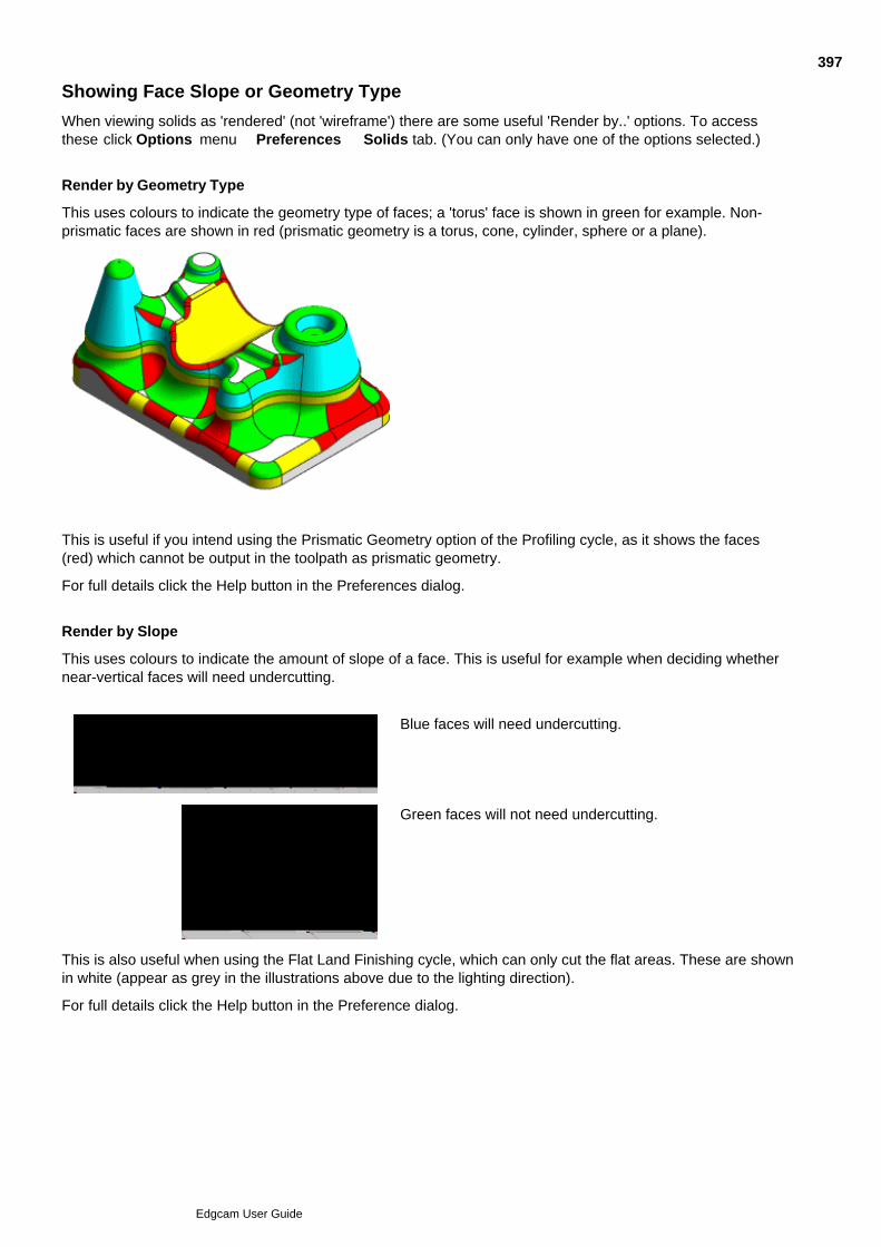
Showing Face Slope or Geometry Type
When viewing solids as 'rendered' (not 'wireframe') there are some useful 'Render by..' options. To accessthese click Options menu Preferences Solids tab. (You can only have one of the options selected.)
Render by Geometry Type
This uses colours to indicate the geometry type of faces; a 'torus' face is shown in green for example. Non-prismatic faces are shown in red (prismatic geometry is a torus, cone, cylinder, sphere or a plane).
This is useful if you intend using the Prismatic Geometry option of the Profiling cycle, as it shows the faces(red) which cannot be output in the toolpath as prismatic geometry.
For full details click the Help button in the Preferences dialog.
Render by Slope
This uses colours to indicate the amount of slope of a face. This is useful for example when deciding whethernear-vertical faces will need undercutting.
Blue faces will need undercutting.
Green faces will not need undercutting.
This is also useful when using the Flat Land Finishing cycle, which can only cut the flat areas. These are shownin white (appear as grey in the illustrations above due to the lighting direction).
For full details click the Help button in the Preference dialog.
397
Edgcam User Guide

Customising with PCIs and PDIs
PDIs can be used to customise Edgecam, allowing geometry and machining commands to be embedded in themenu structure. (Please note that PDIs cannot be used in Edgecam Student Edition).
The PCI macro-based language allows programmers to generate routines; for example, to group standardmachining routines or automate repetitive tasks.
You can easily access your PCIs by creating commands for them, and assigning the commands to toolbars (asbuttons).
You can display PCI Variables in the PCI Variables Window. You can then edit/delete/view variables from thewindow.
Note that you need to refresh the PCI Variables Window to view an up-to-date list of PCI variables. To do thisright-click in the window and select Refresh from the shortcut menu.
There are several ways of adding or changing functionality to Edgecam. These are through the use of PCIsand PDIs.
Creating PCI Templates
PCI Customisation
PDI Customisation
398
Edgcam User Guide

Creating PCI Templates
The creation of PCI templates provides an alternative way of creating a basic PCI based on a sequence ofmanufacturing instructions. The PCI created will contain a user-specified selection of existing instructions, withor without their dialog input and a single form-fill input for the variables used.
The advantages over the more traditional methods of command capture are :
The sequence can be developed and edited until you are satisfied before committing it to PCI form.
The variables used to add flexibility to the PCI will be collected together automatically into a single dialogto be completed at run-time.
Common geometry - used by more than one cycle within the PCI - will be digitised once when running thePCI and this will not need to be repeated for each cycle.
399
Edgcam User Guide

PCI Customisation
PCI is a parametric macro language that works directly on the Edgecam database.
Its main features are:
Save command sequences as ASCII text files. These can replayed to recreate the same or similarsequences of events.
Edit the PCI file to add functionality. Any Edgecam command may be called, with both predefinedmodifier values and digitised information for that command.
Program flow, user input/output, entity selection, string manipulation and calculations are aided by a setof high level directives.
Automatically generates comments during the command save. Further comments can be added at anytime.
Create, call, and delete user-defined variables.
Interactively define and use variables and user input dialogs with the command save facility. Complete‘family of parts’ macros can be developed without further editing. Program flow control based onconditional tests can be added by editing the PCI macro in any text editor.
PCI files can only be created and executed from within the Design and Manufacture modes. This includes theability to initialise the Code Generator and Tool Library and then return to the Manufacture mode to continue asequence.
PCI Variables can be displayed in the PCI Variables Window. From this window you can edit/delete/view thePCI Variables.
PCI files usually work correctly on non-English language versions of Edgecam.
To start finding out about PCIs, see PCI - Command Macros.
400
Edgcam User Guide
PDI Customisation
PDIs are executable programs written to extend the functionality of Edgecam.
A PDI is a library of commands used to perform a particular task. By running a PDI you could, for example,draw a bolt head in one operation.
To run a PDI:
Click the Custom menu then click Run Executable.1.
In the PDI dialog that appears click the Name box and from the drop down list select the PDI.2.
Note that this runs a PDI in the folder 'installation folder\cam\pdi\cat-run'. PDIs that you use in this way arecalled 'category run PDIs'.
(PDIs are also used to provide some of the standard menu commands of Edgecam, such as Rectangle. Theseare in the folder installation folder\cam\pdi\menu-run directory.)
Warning Category-run PDIs cannot be used in Edgecam Student Edition.
Note for Advanced Users - You can produce your own PDIs with the PDI Toolkit. You must also learn aboutthe internal workings of Edgecam.
401
Edgcam User Guide
PCI - Command Macros
PCI is a parametric macro language that works directly on the Edgecam database.
Main Features
Save command sequences as ASCII text files. These can be replayed to recreate the same or similarsequences of events.
Edit the PCI file to add functionality. Any Edgecam command may be called, with both predefinedmodifier values and digitised information for that command.
Program flow, user input/output, entity selection, string manipulation and calculations are aided by a setof high level directives.
Automatically generates comments during the command save. Further comments can be added at anytime.
Create, call, and delete user-defined variables.
Interactively define and use variables and user input dialogs with the command save facility. Complete‘family of parts’ macros can be developed without further editing. Program flow control based onconditional tests can be added by editing the PCI macro in any text editor.
PCI files can only be created and executed from within the Design and Manufacture modes. This includes theability to initialise the Code Generator and Tool Library and then return to the Manufacture mode to continue asequence.
PCI files usually work correctly on non-English language versions of Edgecam.
PCIs that initialise sequences select the discipline by position in the available list. Depending on your licenceconfiguration, this list can change. To avoid problems in this area, set the displine in the PCI to “any|0” andallow the specified Code Generator to dictate the discipline.
402
Edgcam User Guide

Creating PCI Templates
The creation of PCI templates provides an alternative way of creating a basic PCI based on a sequence ofmanufacturing instructions. The PCI created will contain a user-specified selection of existing instructions, withor without their dialog input and a single form-fill input for the variables used.
The advantages over the more traditional methods of command capture are :
The sequence can be developed and edited until you are satisfied before committing it to PCI form.
The variables used to add flexibility to the PCI will be collected together automatically into a single dialogto be completed at run-time.
Common geometry, used by more than one cycle within the PCI will be digitised once when running thePCI and this will not need to be repeated for each cycle.
It is not recommended that PCI templates are saved to the \cam\operates folder because the operation PCIsare stored in it.
See Also
Designing the PCI
Sequence of Events
Building the PCI
Run-Time Variables
Adding Comments and Prompts
Finishing the PCI
Changing the Order of Directives within the PCI
Using Comments within the PCI
403
Edgcam User Guide

Designing the PCI
Even though you are using an auto-generator to create your PCI it is absolutely essential that you have a clearunderstanding of the purpose and limitations of the PCI that you are creating. A brief “design phase” withconclusions noted down before starting work on the PCI will greatly streamline the process.
The following questions should be considered and answered before starting work:
What is the purpose of the PCI?1.
What circumstances must it cater for, what is the likelihood of encountering conditions that it won’t meet?2.
Who will use it, and what is their level of understanding?3.
Will the PCI create a complete sequence or is it intended to generate a series of instructions as part of alarger sequence?
4.
As you create the sequence and ultimately your PCI a further set of questions arise. The earlier in the projectthese are answered the more efficient the PCI creation process will be.
What is the optimum sequence of instructions to be included?1.
Which machining parameters can be safely left as fixed values and which will need to be set up as run-time variables?
2.
Which instructions need to present full dialog interfaces at run-time?3.
Do any of the user prompts need clarification or expansion.4.
A PCI created in an inch environment will run in metric and vice versa but no attempt will be made to convertany values entered. Particular care must be taken in respect of feeds, speeds and cut increments/offsets if thiscircumstance is likely to arise.
See Also
Usual Sequence of Events when Creating a PCI
404
Edgcam User Guide

Sequence of Events
The following provides a guide to the usual sequence of events when creating a PCI.
Decide the purpose and outline requirements of the PCI.1.
Create an Edgecam sequence that performs the desired functions.2.
Decide which cycles will present full dialogs and where run-time variables should replace fixed values.3.
Where necessary, edit the sequence to place variables in the cycles.4.
Make sure that the sequence contains no unnecessary commands.5.
Ensure that the sequence contains adequate comments.6.
Create the PCI.7.
Test the PCI, first on identical geometry and then on variants of the geometry to ensure that it runscorrectly and that prompts etc are adequate.
8.
If necessary, edit the PCI (see Finishing the PCI).9.
If the PCI is intended for general use, always get another user to carry out tests, in addition to your own,before releasing it for production use.
10.
405
Edgcam User Guide
Building the PCI
There are two ways of creating PCI templates.
Select the PCI Template (Custom menu) command, OR
Select the required commands in the Sequence Window. With a right-hand mouse click, open theshortcut menu and select the PCI Template option.
To generate a PCI using the menu command
Select the PCI Template (Custom menu) command. You will be prompted for the PCI file name that youwant to create.
1.
Enter a name for the .pci file. You will be presented with a list of the instructions in the current sequence.2.
Pick the instructions to be included by selecting the individual instructions with a left-hand mouse click.3.
Tip - Selecting Instructions
If required, use the Comments field to display a header/basic description before the initial user requestat run-time. This allows you to explain the purpose of the PCI and to tell the user which geometryelements to select.
4.
To generate a PCI using instructions in the Sequence Window
Select the instructions you want to include in the PCI.1.
With a right-hand mouse click, open the shortcut menu and select the PCI Template option. You will beprompted for the PCI file name that you want to create.
2.
It is not recommended that PCI templates are saved to the \cam\operates folder because the operation PCIsare stored in it. We suggest you save your PCI templates to the \cam\pci folder in your Edgecam installation.
See Also
Selecting Instruction Dialogs
Selecting Geometry
406
Edgcam User Guide

Selecting Instruction Dialogs
It is possible that at run-time you will want your PCI to give users the opportunity to change the parameters ofone or more cycles. The next stage in PCI creation is to select those instructions.
You will be presented a list of instructions containing all those instructions that were previously picked for thePCI.
Highlight the instructions that you want to show an input dialog.1.
Press OK to complete.2.
Your PCI will now be automatically created. PCIs created using the PCI Template command will generate a“Define Operation” record containing the name of the PCI in the sequence of instructions .
407
Edgcam User Guide

Selecting Geometry
When the PCI is created any geometry used by more than one cycle will be identified and at run-time the userwill be given a single prompt to select it at the start of the PCI.
If you want to give users of the PCI additional instructions for selecting geometry they can easily be added tothe basic PCI. You can either add these instructions at the time of PCI creation by using the Add Comment (M-Functions menu) command (see Adding Comments and Prompts) or at a later stage in an editor (see Finishingthe PCI).
408
Edgcam User Guide

Run-Time Variables
To give users of the PCI flexibility you may want to use variables in certain dialog fields instead of fixed values.Where only one or two fields are variable this may be preferable to displaying the whole dialog.
Any numeric entry field can be filled with a user-defined variable. Simply enter the variable name in theappropriate field, enclosed in square brackets [ ]. For example you may wish to give the user the ability tospecify the cut increment for a profile cycle – Use [Finish-Profile-Cut-Increment].
When you use a variable in this way you will be prompted to enter a value. This value will become thedefault value in the PCI variable input dialog, which is displayed for data input at run-time. All thevariables in a PCI are collected together in a single dialog at the beginning.
Each PCI variable must be unique within an individual PCI and for the purposes of automatically createdPCIs the names should be self-explanatory in meaning.
Note that if a cycle is to present a full input dialog at run-time there is no point in placing named variables in theinput fields.
409
Edgcam User Guide
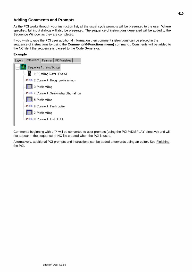
Adding Comments and Prompts
As the PCI works through your instruction list, all the usual cycle prompts will be presented to the user. Wherespecified, full input dialogs will also be presented. The sequence of instructions generated will be added to theSequence Window as they are completed.
If you wish to give the PCI user additional information then comment instructions can be placed in thesequence of instructions by using the Comment (M-Functions menu) command . Comments will be added tothe NC file if the sequence is passed to the Code Generator.
Example
Comments beginning with a ‘?’ will be converted to user prompts (using the PCI %DISPLAY directive) and willnot appear in the sequence or NC file created when the PCI is used.
Alternatively, additional PCI prompts and instructions can be added afterwards using an editor. See Finishingthe PCI.
410
Edgcam User Guide

Finishing the PCI
The automatically generated PCI will be in the form of a text file which can, if you wish, be edited to make iteven more flexible or to give the user additional information.
Simple additions can be made to make the PCI more specifically applicable to your own circumstances, usingany valid PCI directive. See PCI Directives.
You may find the following directives especially useful:
To add additional instructions or information for the user
To add more variables or to subdivide the automatically generated form
To change the prompt shown to the user when digitising geometry
Run-time environment
Your PCI template will contain a check to ensure that it is run in the correct machining environment, therefore alathe PCI cannot be run in mill mode. If you want to use, for example, a mill PCI on CY lathe parts it isnecessary to modify the %IF [&3AXMILLL] = 0 statement in the PCI. See PCI System Variables.
Please note that PCI templates have not been designed for use in the wire environment. If used, severelimitations will be encountered.
411
Edgcam User Guide
Changing the Order of Directives within the PCI
This is not recommended until you have gained experience in writing and using PCIs as placing directives inthe wrong context or position could alter the way in which a PCI behaves.
The commands in a PCI mostly relate to the instructions in the Edgecam sequence with the directives grouprelating to each instruction starting with a %InitCommand= directive and finishing with a %ExecCommanddirective.
Example
%InitCommand=cmd0=7,108
%ClearMods=[cmd0]
* Setting modifier 'Comment'
%SetModifier=[cmd0],15,Rough Turn from billet
%ExecCommand=nRet=[cmd0],-1
In general, if you want to move %DISPLAY or %ASKBOX directives to alternative positions in the PCI theyshould be placed between such instruction groups rather than in the middle of them.
412
Edgcam User Guide

Using Comments within the PCI
Comments for your own information when maintaining the PCI should start with a “*” character. Any line startingwith “*” will have no effect on the PCI.
Example
* Request for additional variable data
* Finishing profile command
Remember that * comments are for the PCI writer’s benefit only. Users of the PCI will not see them as the PCIruns.
Note that the auto-generation process places a number of comments in the PCI file anyway to make it easier tounderstand:
Example
* Setting modifier 'Gauge Point'
%SetModifier=[cmd0],214,Orthogonal|3
413
Edgcam User Guide
Creating a Simple PCI
The following sequence lists the actions required to create a PCI file. The PCI is to be able to prompt the userto specify the height, length and origin for a rectangle.
Display the PCI Variables Window.1.
Activate the command save – Command Save On (Custom menu).2.
Request parameters for rectangle – Define Askbox (Custom menu).3.
Enter Prompt string for rectangle height – for example, “Enter rectangle height”.
Enter Variable name for rectangle height – for example, HEIGHT.
Enter Prompt string for rectangle width – for example, “Enter rectangle width”.
Enter Variable name for rectangle width – for example, WIDTH.
Select the Complete option to indicate that parameter definition is complete. A dialog box displays theprompts.
3.
Enter the initial values for the height and width, and select OK.4.
Right click on the PCI Variable tab in the window and select New from the shortcut menu to open theDefine Variable dialog.
5.
Enter Prompt String for origin – for example, Digitise origin for rectangle.6.
Select Digitise from the list for the Numeric value option7.
Enter Variable name for rectangle origin – for example, ORIGIN.8.
Select OK and digitise the location of the initial origin (specific co-ordinates can be entered via the Co-ordinate input sub-modifier).
9.
Select the Polyline button.10.
Select the Co-ordinate input button, and enter these lines in the command box (including commas).When you run this PCI, the ORIGIN, WIDTH and HEIGHT variables will be replaced by the values youtype in. ORIGIN is slightly different because the variable contains an X, Y and a Z value. You can specifythe co-ordinate by prefixing ORIGIN with 'X@', 'Y@', or 'Z@', as shown below.
11.
X[X@ORIGIN]Y[Y@ORIGIN],
IX[WIDTH],IY[HEIGHT],IX-[WIDTH],IY-[HEIGHT]
Select the Finish button.12.
Complete the PCI save by selecting the Command Save Off (Custom menu) command, and define adirectory path and filename to which the PCI is saved.
13.
The PCI can then be accessed from the Run command file (Custom menu), by selecting the file.
See Also
The Simple PCI Example File
414
Edgcam User Guide
The Simple PCI Example File
This PCI will create a rectangle after prompting the user for height, width and the rectangle origin. Thesevalues are held in the variables HEIGHT, WIDTH and @ORIGIN respectively. This example also containsinline comments that have been generated automatically during the command save.
%ASKBOX=Enter rectangle height=height=Enter rectangle width=width
%ASKDIG=Digitise origin for rectangle=origin
* Initialising command:- Line
%INITCOMMAND=cmdh=2,1
%CLEARMODS=[cmdh]
* Setting modifier 'Polyline'
%SETMODIFIER=[cmdh],155,1
* Setting modifier 'Colour'
%SETMODIFIER=[cmdh],1,Aquamarine|20
* Setting modifier 'Layer'
%SETMODIFIER=[cmdh],3,15
* Setting modifier 'Style'
%SETMODIFIER=[cmdh],2,Solid|0
%INITDIGINFO=gdh1
* Add Free dig to Digitised input data
%ADDFREEDIG=[gdh1],PX[X@ORIGIN]Y[Y@ORIGIN]
* Add Free dig to Digitised input data
%ADDFREEDIG=[gdh1],IX[WIDTH]
* Add Free dig to Digitised input data
%ADDFREEDIG=[gdh1],IY[HEIGHT]
* Add Free dig to Digitised input data
%ADDFREEDIG=[gdh1],IX-[WIDTH]
* Add Free dig to Digitised input data
%ADDFREEDIG=[gdh1],IY-[HEIGHT]
* Finish Digitised input
%ADDFINISHDIG=[gdh1],[#FINISH]
%EXECCOMMAND=cmdret=[cmdh],[gdh1]
%FREEDIGINFO=[gdh1]
415
Edgcam User Guide
PCI Syntax
PCI Directives and variables are not case-sensitive and can be identified by their prefix. Here is a list ofprefixes and other syntax used within the PCI system:
% PCI directive prefix, for example %ASKBOX
$ String variable prefix, for example $array
X@ Digitised position variable prefix, holding the X co-ordinate
Y@ Digitised position variable prefix, holding the Y co-ordinate
Z@ Digitised position variable prefix, holding the Z co-ordinate
& System variable prefix, for example &PLUNGEFEED
# Read-only variable prefix, for example #FREEDIG
* Comment line, not processed by the PCI system, for example
* This is a comment line
[ ] Use the contents of these brackets, for example%IF[ANG]=>[EANG]%GOTO=endloop
( ) Perform an operation in these brackets first, as in standard mathematical notation
416
Edgcam User Guide

About PCI Directives
Directives are the key components of a PCI macro and control all aspects of program flow, commandexecution, and variable assignment and manipulation. Each directive is identified by a ‘%’ prefix. All PCIdirective names are case insensitive.
417
Edgcam User Guide
About PCI Variables
Variables may be used in almost any PCI directive. When a PCI is executed, Edgecam substitutes the variablefor its currently defined value prior to execution of that directive, allowing true parametric programming.
Variable names can be up to 28 characters long and are case insensitive.
Variables are assigned values in a PCI macro using either the %CALC, %ASK, %ASKBOX, %OPTION or%ASKDIG directives.
During a command save, users may define their own variables. These variables can then be used withincommand dialogs and digitised input.
If the variable name is surrounded by square brackets within a PCI file or Edgecam command, the applicationuses the value associated to that variable.
When a variable name is entered in a parameter field on a command dialog, you can view its value by selectingthe name and then simultaneously pressing the Ctrl and ‘=’ keys on the keyboard. Release the keys to switchback to the variable name.
Example
If you have defined the variable 'RADIUS', you could enter it into one of the parameter fields whencreating an arc.
1.
Pressing the Ctrl and '=' keys displays the current value for the variable:2.
See Also
PCI Variable Types
418
Edgcam User Guide
PCI Variable Types
There are a number of different variable types available, named according to the following conventions:
String String variables contain alphanumeric text and must be preceded by an ‘$’ toidentify them. Typically these would be used for text creation, filenames or useridentification in an Edgecam command. String variables may be up to 80characters in length.
Digitised These are preceded by an ‘@’ and refer to a digitised position. These positionsare 3D and therefore have an X, Y and Z component. The X, Y and Zcomponents of the digitised variable @ORIGIN can be referred to asX@ORIGIN, Y@ORIGIN and Z@ORIGIN respectively.
Numeric These have no prefix and can contain any floating point or integer value.
System These are set up by Edgecam and are prefixed by ‘&’. A typical example wouldbe &NEXTENT, which defines the next available entity number in thedatabase. A full definition of all system variables is included in the referencesection of this specification.
Read only These are preceded by a ‘#’ character and can only be written-to once. Theyalways have a numeric value. All subsequent writes using different valuesgenerate an error.
These are typically used to add clarity to a macro and are used to identify socalled ‘magic numbers’. For instance, the number that indicates a user hasselected a free digitise position is defined as #FREEDIG. This and a number ofother read only variables are created by the system when initialising acommand save or executing a PCI macro.
419
Edgcam User Guide

Compatibility Problems with PCIs
It is possible that software changes can lead to compatibility problems when using PCIs written for earlierversions of the software.
In response to requests from the user base we have introduced a PCI variable that allows you to use PCIs thatwere written before the Trim (Edit menu) command was altered.
If the user PCI variable "TrimEmulationMode" is set to a numeric value then the behaviour is as follows:
Numeric value Behaviour
0 Same as if variable not set, normal behaviour of command. Thebreak option will always keep the start of the broken entity asthe original entity number.
1 Normal behaviour of the trim command except for the breakoption which will try to keep as the original entity the brokensection nearest the second intersection point (or the firstdigitised point if only one intersection). Note this is close but notexactly the same as the old command's behaviour.
2 Use the command as shipped prior to Edgecam version 5.50.0which is limited to the current CPL and lines/arcs.
420
Edgcam User Guide

PCI Comments
Comments are lines prefixed by an ‘*’, that are not processed when the PCI is run, and are typically used todocument various parts of a PCI program.
Full inline comments can be automatically generated or user specific comments specified at any time duringthe command save process.
Comments can also be added by manually editing the resultant PCI macro file.
421
Edgcam User Guide
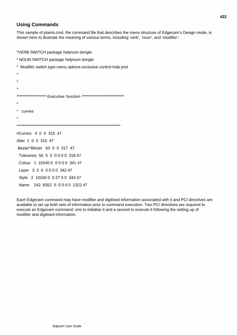
Using Commands
This sample of ptams.cmd, the command file that describes the menu structure of Edgecam’s Design mode, isshown here to illustrate the meaning of various terms, including ‘verb’, ‘noun’, and ‘modifier’:
*VERB SWITCH package helpnum dongle
* NOUN SWITCH package helpnum dongle
* Modifier switch type menu options exclusive control help prot
*
*
*
******************* Executive function ***************************
*
* curves
*
******************************************************************
#Curves 4 0 0 315 47
Alter 1 0 0 316 47
Bezier^Bèzier 63 0 0 317 47
Tolerance 56 5 0 0 0 0 0 318 47
Colour 1 10240 0 0 0 0 0 341 47
Layer 3 2 0 0 0 0 0 342 47
Style 2 10240 0 0 27 0 0 343 47
Name 242 8352 0 0 0 0 0 1322 47
Each Edgecam command may have modifier and digitised information associated with it and PCI directives areavailable to set up both sets of information prior to command execution. Two PCI directives are required toexecute an Edgecam command: one to initialise it and a second to execute it following the setting up ofmodifier and digitised information.
422
Edgcam User Guide

Using Modifiers
Each Edgecam command can have a number of modifiers each with its own identifying number between 1 and255.
When a modifier value is set, its modifier number and its requested value must be specified. Many Edgecammodifiers offer a drop down list for selection, but the selected option always translates to a numeric value insideEdgecam.
Because of this, PCI needs that number when setting the value for a drop-down list type modifier. One exampleis colour, where Blue is referenced as Blue|2 in the command save file. The associated number relates to thecolour’s position on the drop down list, so Green=1, Blue=2, Cyan=3 and so on, from 1 to 32.
In a similar way, the line style font number is based on its position on the list, except that the list goes from 0 to3, so Solid=0, Dotted=1, Dashed=2, and Chained=3. Note that the text before the ‘|’ is unnecessary.
If the command save facility is used to generate the PCI macro, this information is generated automatically.The %TOOLBARMODS directive can also be used to access the current toolbar settings for colour, style andlayer information.
423
Edgcam User Guide

About the Database, Entity Numbers and Names
Edgecam supports a number of different entity types as detailed in the reference section of this document. TheEdgecam database is the data structure that contains all this information.
Each entity is given a unique number when created and PCI may reference each entity by this number.
However, this number may change in subsequent worksession, depending on which defaults file has beenloaded and which entities have been deleted. This makes writing PCI macros that reference existing databaseentities quite difficult. PCI system variables do give access to the number of entities in an empty part and thetotal number of entities present in the database at any one time (&BASEENT and &NEXTENT).
To simplify this problem, Edgecam also allows entities to be accessed by an entity name, for example by usingthe %ADDENTNAMEDIG directive. The entity name is always unique and does not change. Entity names of upto eight characters are supported. If the name has already been used in the database, Edgecam generates aunique name by appending ‘.n’ (where n is a number between 1 and 999) to the specified name.
Most entity types can be digitised at either end. A direction flag indicates which end of the entity has beendigitised. With a line entity, the direction flag will be zero if the start of the line is digitised, or 1 if the end of theline is digitised.
When creating PCI macros to refer to existing geometry, we recommend that you name the geometric entities.
About Handles
A ‘Handle’ is the name of a memory storage area. This area is where all digitised information for the PCI isplaced, including any geometric or toolpath entities created when the PCI is executed.
The default name given to this handle in the PCI commands is ‘gdh1’. You can edit this to any desired name.
424
Edgcam User Guide

How to Execute Commands
During a command sequence save, the following process is typical for each command executed:
Initialise the command using the %INITCOMMAND directive.1.
Clear all modifier fields for the Create command using %CLEARMODS.2.
Set the modifier defaults as using %SETMODIFIER directives.3.
Optionally Display the modifier dialog for the command, and allow the user to alter the default modifiersvalues using the %ASKMODS directive.
4.
Initialise the digitise buffer to store digitises made by the user using %INITDIGINFO.5.
Add the digitised information to the buffer set up by %INITDIGINFO using a series of %ADDFREEDIG,%ADDENTNODIG, %ADDENTNAMEDIG, %ADDFINISHDIG or %ADDDIGINFO directives.
6.
Execute the command with the handle (the name of a memory storage area) set up by %INITCOMMANDand the digitise information set up by %INITDIGINFO using %EXECCOMMAND.
7.
Free up the digitise handle set up by %INITDIGINFO, ready for the next command using%FREEDIGINFO.
8.
425
Edgcam User Guide

About PCI Text Files
The PCI text file is an ASCII format file that can be edited in any text editor.
A text file can be written ‘from scratch’ or a template created automatically from a command save. In practice acombination of methods is used.
PCI file names have the extension .PCI and maybe up to 256 characters in length. Text files are subject to anylimitations imposed by the operating system.
426
Edgcam User Guide

Writing Programs
A command sequence save usually provides the best template for a PCI, because it supplies all of the relevantinformation to recreate the geometry and other information.
User variables can be added during a command save or added later along with flow control directives whereappropriate to add parametric capability.
427
Edgcam User Guide

Editing Programs
PCI files can be constructed in many ways, for example, by cutting and pasting existing PCIs into a single file,or by adding flow control and interactive calls to a command sequence save.
Comments can be used to mark a specific area of a file, or typically to indicate when another PCI has beencalled from within the command save.
428
Edgcam User Guide

Debugging Programs
Edgecam contains a useful feature, the %DEBUG directive, that allows you to step through the PCI file andview the contents (including the name and value of variables).
The %DEBUG directive toggles debugging on or off. You can direct the output to screen or disk.
429
Edgcam User Guide

Calling a PDI from a PCI
PDI programs that have been integrated into the command structure (that is, called from menubar.dfn) arewritten to the PCI file in the same way as commands from the .cmd files. Use Command Save to capture thecommand format.
Category-run PDIs can also be saved to the file and are activated on re-execution of the PCI.
430
Edgcam User Guide

Calling a PCI from a PCI
One PCI can call another PCI using the %INCLUDE directive.
This allows ‘nesting’ of PCIs, and makes ‘master’ PCIs (the PCIs using the %INCLUDE directive) moremanageable and smaller in size.
If a second PCI is executed during a command save, you can see this as a single %INCLUDE in the resultantPCI file.
431
Edgcam User Guide

Using PCI Commands
All PCI operations are called from the Custom option of the Menu bar within the Design and Manufacturemodes.
See Also
Switching On a 'Command Save'Switching Off a 'Command Save'Aborting a 'Command Save'Running a Command FileDefining VariablesDefining a Dialog BoxViewing the Contents of VariablesUsing Arrays in PCIs
432
Edgcam User Guide

Aborting a 'Command Save'
A command sequence save can be aborted at any time by selecting the Abort Command Save (Custommenu) option.
433
Edgcam User Guide

Adding Comments to a 'Command Save'
The Add Comments (Custom menu) command enables you to add unique comments “on the fly” during acommand sequence save. A single line comment of up to a limit of 256 characters can be saved.
434
Edgcam User Guide
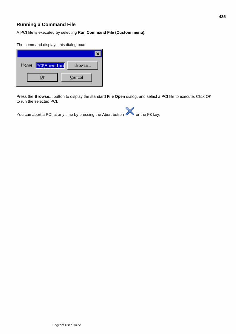
Running a Command File
A PCI file is executed by selecting Run Command File (Custom menu).
The command displays this dialog box:
Press the Browse... button to display the standard File Open dialog, and select a PCI file to execute. Click OKto run the selected PCI.
You can abort a PCI at any time by pressing the Abort button or the F8 key.
435
Edgcam User Guide
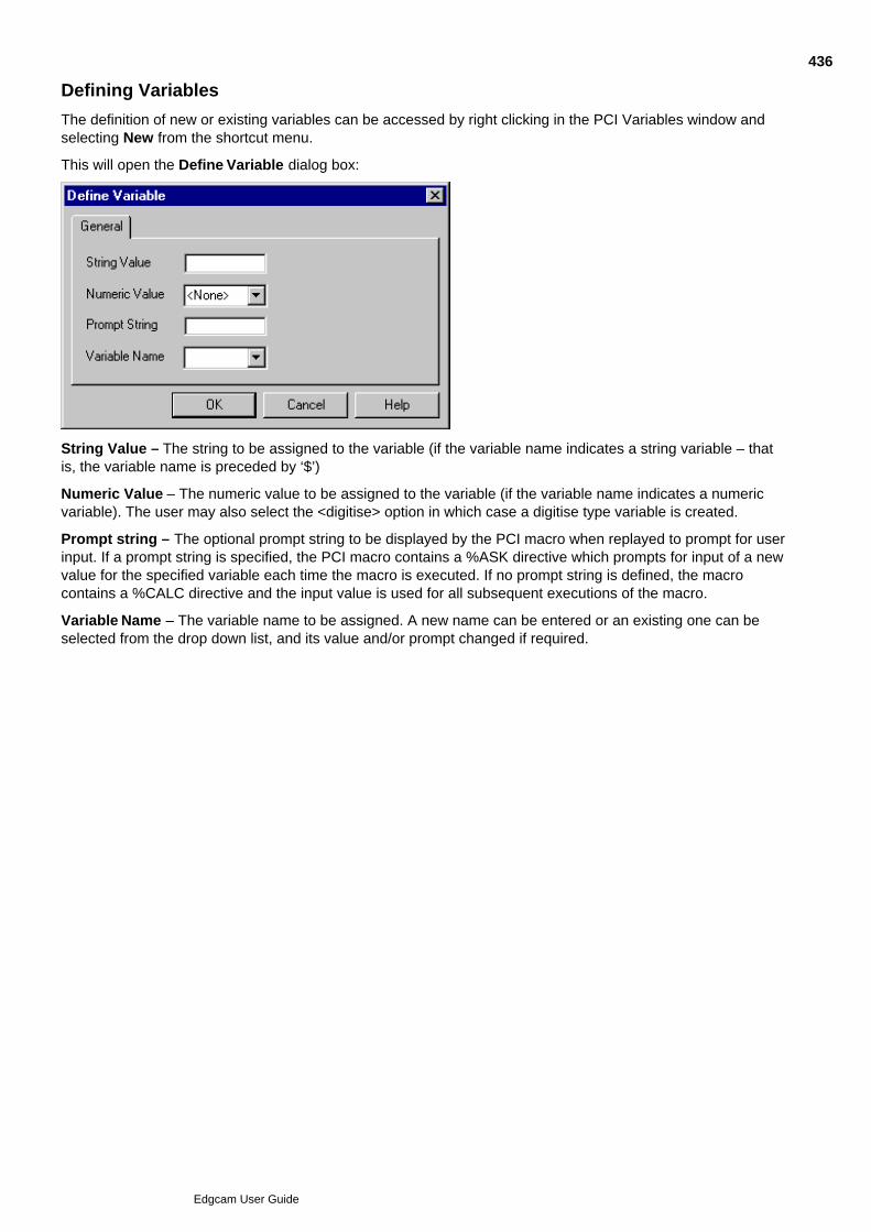
Defining Variables
The definition of new or existing variables can be accessed by right clicking in the PCI Variables window andselecting New from the shortcut menu.
This will open the Define Variable dialog box:
String Value – The string to be assigned to the variable (if the variable name indicates a string variable – thatis, the variable name is preceded by ‘$’)
Numeric Value – The numeric value to be assigned to the variable (if the variable name indicates a numericvariable). The user may also select the <digitise> option in which case a digitise type variable is created.
Prompt string – The optional prompt string to be displayed by the PCI macro when replayed to prompt for userinput. If a prompt string is specified, the PCI macro contains a %ASK directive which prompts for input of a newvalue for the specified variable each time the macro is executed. If no prompt string is defined, the macrocontains a %CALC directive and the input value is used for all subsequent executions of the macro.
Variable Name – The variable name to be assigned. A new name can be entered or an existing one can beselected from the drop down list, and its value and/or prompt changed if required.
436
Edgcam User Guide
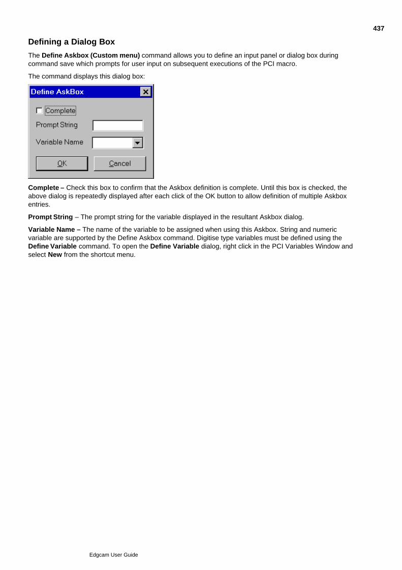
Defining a Dialog Box
The Define Askbox (Custom menu) command allows you to define an input panel or dialog box duringcommand save which prompts for user input on subsequent executions of the PCI macro.
The command displays this dialog box:
Complete – Check this box to confirm that the Askbox definition is complete. Until this box is checked, theabove dialog is repeatedly displayed after each click of the OK button to allow definition of multiple Askboxentries.
Prompt String – The prompt string for the variable displayed in the resultant Askbox dialog.
Variable Name – The name of the variable to be assigned when using this Askbox. String and numericvariable are supported by the Define Askbox command. Digitise type variables must be defined using theDefine Variable command. To open the Define Variable dialog, right click in the PCI Variables Window andselect New from the shortcut menu.
437
Edgcam User Guide
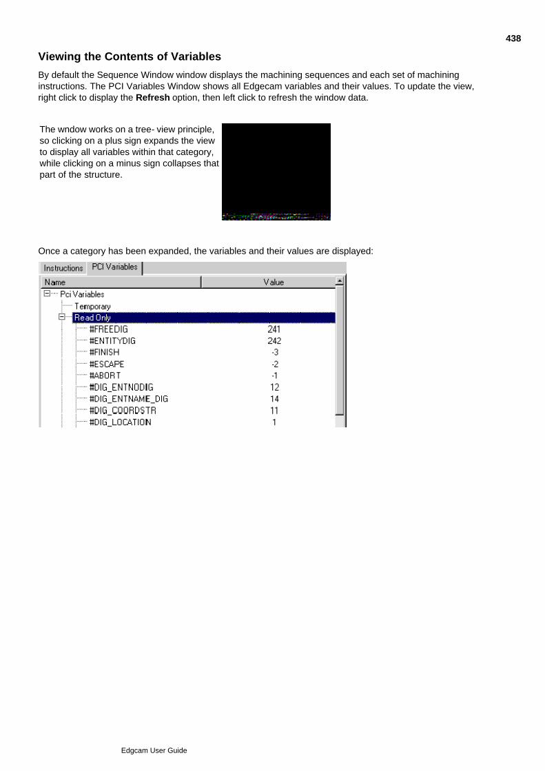
Viewing the Contents of Variables
By default the Sequence Window window displays the machining sequences and each set of machininginstructions. The PCI Variables Window shows all Edgecam variables and their values. To update the view,right click to display the Refresh option, then left click to refresh the window data.
The wndow works on a tree- view principle,so clicking on a plus sign expands the viewto display all variables within that category,while clicking on a minus sign collapses thatpart of the structure.
Once a category has been expanded, the variables and their values are displayed:
438
Edgcam User Guide

Using Arrays in PCIs
Arrays can be used within PCIs by specifying one or more indices in a variable name. Variables are evaluatedas indices enclosed in square brackets [ ].
Key features of PCI array variables:
Can be used in place of an ordinary PCI variable
Multi-dimensional arrays are possible
Storage is only allocated for array elements used
No restriction on array indices (can be negative or even non-numeric)
See Also
About Arrays
Example of a One Dimensional Array
Mixing String and Numeric Variables
Evaluating Variables in an Array
Example of a Two Dimensional Array
439
Edgcam User Guide
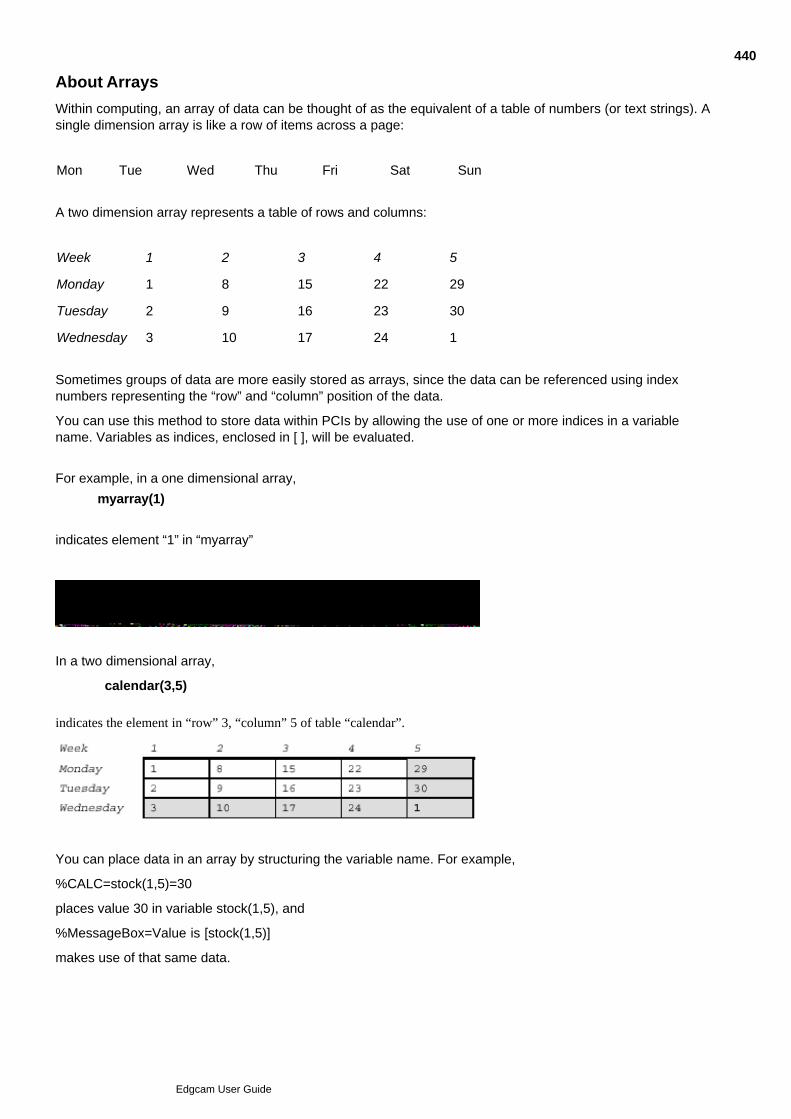
About Arrays
Within computing, an array of data can be thought of as the equivalent of a table of numbers (or text strings). Asingle dimension array is like a row of items across a page:
Mon Tue Wed Thu Fri Sat Sun
A two dimension array represents a table of rows and columns:
Week 1 2 3 4 5
Monday 1 8 15 22 29
Tuesday 2 9 16 23 30
Wednesday 3 10 17 24 1
Sometimes groups of data are more easily stored as arrays, since the data can be referenced using indexnumbers representing the “row” and “column” position of the data.
You can use this method to store data within PCIs by allowing the use of one or more indices in a variablename. Variables as indices, enclosed in [ ], will be evaluated.
For example, in a one dimensional array,
myarray(1)
indicates element “1” in “myarray”
In a two dimensional array,
calendar(3,5)
indicates the element in “row” 3, “column” 5 of table “calendar”.
You can place data in an array by structuring the variable name. For example,
%CALC=stock(1,5)=30
places value 30 in variable stock(1,5), and
%MessageBox=Value is [stock(1,5)]
makes use of that same data.
440
Edgcam User Guide

See Also
Example of a One Dimensional ArrayMixing String and Numeric VariablesEvaluating Variables in an ArrayExample of a Two Dimensional Array
441
Edgcam User Guide
Example of a One Dimensional Array
The following example initialises a one dimensional array with the values 1 through 10, displays the contents,reverses the array and shows the reversed contents of the array.
Running the PCI displays a dialog with the text:
Initialised TestArray(1 - 10) 1 2 3 4 5 6 7 8 9 10
Click OK to display a dialog with the text:
Reversed TestArray(1 - 10) 10 9 8 7 6 5 4 3 2 1
* Initialise TestArray() with 1 2 3 4 5 6 7 8 9 10
%CALC=Index=0
%LABEL=Initialise
%CALC=Index=[Index]+1
%CALC=TestArray([Index])=[Index]
%IF [Index] < 10 %GOTO=Initialise
%CALC=$Title=Initialised
%GOSUB=DisplayArray
* Now Reverse the array
%CALC=Forward=1
%CALC=Reverse=10
%LABEL=RevLoop
* Swap array elements
%CALC=Temp=[TestArray([Reverse])]
%CALC=TestArray([Reverse])=[TestArray([Forward])]
%CALC=TestArray([Forward])=[Temp]
* Loop for half the array
%CALC=Forward=[Forward]+1
%CALC=Reverse=[Reverse]-1
%IF [Reverse] > 5 %GOTO=RevLoop
%CALC=$Title=Reversed
%GOSUB=DisplayArray
%END
* Display contents of array
%LABEL=DisplayArray
%CALC=$ArrayContent=
442
Edgcam User Guide
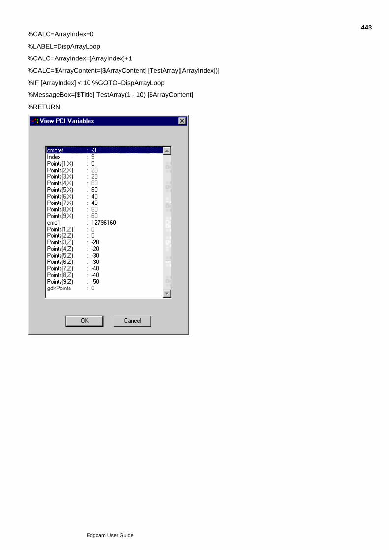
%CALC=ArrayIndex=0
%LABEL=DispArrayLoop
%CALC=ArrayIndex=[ArrayIndex]+1
%CALC=$ArrayContent=[$ArrayContent] [TestArray([ArrayIndex])]
%IF [ArrayIndex] < 10 %GOTO=DispArrayLoop
%MessageBox=[$Title] TestArray(1 - 10) [$ArrayContent]
%RETURN
443
Edgcam User Guide

Mixing String and Numeric Variables
The array mechanism works by text substitution in the variable name. You can mix string and numeric variablesas array indices. Array variable contents can be numeric or string as dictated by the name (use leading $ forstrings). Expressions may not be used in indices.
* This is legal%CALC=array([$name],[number])=6
* This is illegal%CALC=array([number]+2)=6
444
Edgcam User Guide

Evaluating Variables in an Array
Variable evaluation works from the innermost [ ] outwards. In the following example demonstrates theevaluation of variables.
%CALC=$array(3,9)=HARRY%CALC=number=9%CALC=$string=ber%MessageBox=[$array(3,[num[$string]])]
Evaluation steps for the %MessageBox line are:
%MessageBox=[$array(3,[num[$string]])]1.
%MessageBox=[$array(3,[number])]2.
%MessageBox=[$array(3,9)]3.
%MessageBox=HARRY4.
445
Edgcam User Guide
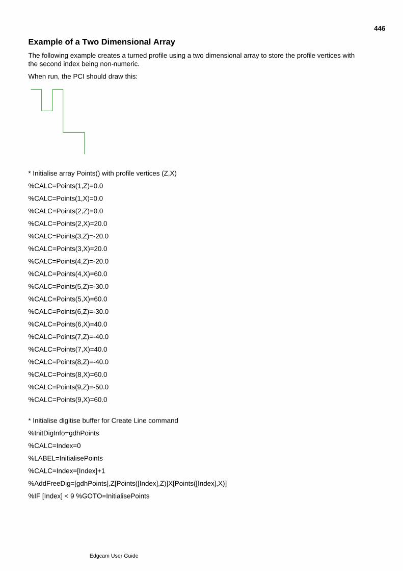
Example of a Two Dimensional Array
The following example creates a turned profile using a two dimensional array to store the profile vertices withthe second index being non-numeric.
When run, the PCI should draw this:
* Initialise array Points() with profile vertices (Z,X)
%CALC=Points(1,Z)=0.0
%CALC=Points(1,X)=0.0
%CALC=Points(2,Z)=0.0
%CALC=Points(2,X)=20.0
%CALC=Points(3,Z)=-20.0
%CALC=Points(3,X)=20.0
%CALC=Points(4,Z)=-20.0
%CALC=Points(4,X)=60.0
%CALC=Points(5,Z)=-30.0
%CALC=Points(5,X)=60.0
%CALC=Points(6,Z)=-30.0
%CALC=Points(6,X)=40.0
%CALC=Points(7,Z)=-40.0
%CALC=Points(7,X)=40.0
%CALC=Points(8,Z)=-40.0
%CALC=Points(8,X)=60.0
%CALC=Points(9,Z)=-50.0
%CALC=Points(9,X)=60.0
* Initialise digitise buffer for Create Line command
%InitDigInfo=gdhPoints
%CALC=Index=0
%LABEL=InitialisePoints
%CALC=Index=[Index]+1
%AddFreeDig=[gdhPoints],Z[Points([Index],Z)]X[Points([Index],X)]
%IF [Index] < 9 %GOTO=InitialisePoints
446
Edgcam User Guide
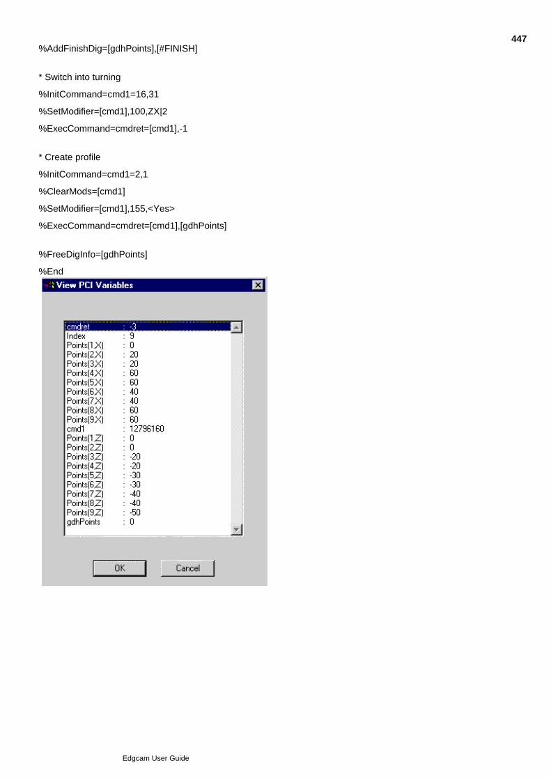
%AddFinishDig=[gdhPoints],[#FINISH]
* Switch into turning
%InitCommand=cmd1=16,31
%SetModifier=[cmd1],100,ZX|2
%ExecCommand=cmdret=[cmd1],-1
* Create profile
%InitCommand=cmd1=2,1
%ClearMods=[cmd1]
%SetModifier=[cmd1],155,<Yes>
%ExecCommand=cmdret=[cmd1],[gdhPoints]
%FreeDigInfo=[gdhPoints]
%End
447
Edgcam User Guide

Building an Operation
These directives allow a PCI to build an Edgecam dialog using a combination of modifiers from previouslyinitialised commands and user defined variables. This means that you can specify all information required for asingle operation within a single dialog. This dialog will optionally have a number of tabs allowing more complexoperations to present information clearly (the ‘button’ method for addressing other pages on an Edgecamdialog is not available for PCI operations). To build a PCI operation
Step 1 - Initialise the OperationStep 2 - Initialise the Edgecam Commands to be used in the OperationStep 3 - Clear All Previous Modifier ValuesStep 4 - Set Any Default Modifier ValuesStep 5 - Build a Dialog for User InputStep 6 - Add Any User Defined Modifiers to the DialogStep 7 - Set Up Mutual Inclusion Relationships Between ModifiersStep 8 - Prompt for Selection of PCI Operation ModifiersStep 9 - Select Entities Used in the OperationStep 10 - Execute Each Edgecam CommandStep 11 - Free the PCI Operation reference
448
Edgcam User Guide

Step 1 - Initialise the Operation
The PCI first initialises a new Edgecam operation using %INITOPERATION. A variable name is defined andthis is used as reference to the operation in subsequent steps. A name for this operation is also given.
In the PCI this appears as:
%INITOPERATION=OperationId=Rough Face Mill,EdgeOp.hlp,10021
OperationId is the PCI variable used to identify the operation.
“Rough Face Mill” is the textual name of the operation. This string is also used as the title of the operationdialog when displayed to the user and for the name of the operation displayed in the Edgecam operations list.
EdgeOp.hlp is the name of the help file to be used to display context sensitive help. This will be located in thelanguage directory in the normal way.
10021 is the help context ID for this command.
The help file name and the context ID are optional parameters.
449
Edgcam User Guide

Step 2 - Initialise the Commands to be used in the Operation
The Rough Face Mill operation is made up of a number of steps. Here is a typical sequence for the ‘RoughFace Mill’:
Select Tool.1.
Positioning Move prior to Facemill Cycle.2.
Edgecam Facemill Cycle.3.
Rapid tool to Home Position.4.
Each step corresponds to an Edgecam machining command. The PCI initialises each Edgecam command tobe used.
%InitCommand=cmdMillTool=36,108%InitCommand=cmdRapidMove=101,1%InitCommand=cmdFaceMill=102,4%InitCommand=cmdHome=101,40
An additional parameter will be added to the %InitCommand directive to disable the validation of a commandbased on the currently selected tool.
450
Edgcam User Guide

Step 3 - Clear All Previous Modifier Values
Since the commands are initialised out of context, the modifiers for the commands are not set up in the normalway. Modal values are not loaded, and neither are lists that are initialised dynamically by the command. To aidclarity in the PCI, all modifiers for all commands used in an operation will be cleared using %CLEARMODS:
%CLEARMODS=[cmdMillTool]%CLEARMODS=[cmdRapidMove]%CLEARMODS=[cmdFaceMill]%CLEARMODS=[cmdHome]
451
Edgcam User Guide

Step 4 - Set Any Default Modifier Values
Any hard-coded modifier values are now set. These are modifiers the user does not need to alter on anoperation by operation basis. Alternatively a PCI variable may have been defined previously which contains thevalue to be used for a particular modifier.
In this operation the tool type is always considered to be an Endmill. The Clearance plane has been previouslydefined by user variable ZCLEAR.
The PCI sets up default values using %SETMODIFIER, as shown below.
%SETMODIFIER=[cmdMillTool],100,EndMill|0%SETMODIFIER=[cmdFaceMill],28,[ZCLEAR]
A number identifies each modifier. Tooltype is modifier 100, Z Clear is modifier 28. Full details of all modifiersare defined in edgekrnl.txt.
452
Edgcam User Guide
Step 5 - Build a Dialog for User Input
Each time the operation is executed, the user will be prompted to supply values for Tool Diameter, ToolPosition, Spindle Speed and Feedrate.
The PCI creates a dialog containing these modifiers using %ADDCMDMODTOOPERATION. Feed and Speedare placed on a separate tab, labelled ‘Cutting Data’. The tooling parameters are placed on the primary page.By default this is labelled ‘General’. Also, the separator can be specified by appending ^Separator_name to thetab name.
%ADDCMDMODTOOPERATION=[OperationID],[cmdMillTool],47
%ADDCMDMODTOOPERATION=[OperationID],[cmdMillTool],116
%ADDCMDMODTOOPERATION=[OperationID],[cmdMillTool],48
%ADDCMDMODTOOPERATION=[OperationID],[cmdFaceMill],5,Cutting Data^Feedrates
%ADDCMDMODTOOPERATION=[OperationID],[cmdFaceMill],6,Cutting Data^Feedrates
%ADDCMDMODTOOPERATION=[OperationID],[cmdFaceMill],7,Cutting Data
Again, a number defines each modifier. 47 = Diameter, 116 = Units, 48 = Position, 5 = Planar Feed, 6 = PlungeFeed and 7 = Spindle Speed.
An additional parameter allows you to specify mutual exclusivity of operation modifiers. This is a bit-orientedvalue and is applied as follows:
%ADDCMDMODTOOPERATION=[OperationID],[cmdMillTool],48,,1
%ADDCMDMODTOOPERATION=[OperationID],[cmdFaceMill],5,Cutting Data,1
Each modifier with the same bit field set is considered to be mutually exclusive. You can set up mutualexclusivity between several modifiers by assigning multiple fields of the bit-oriented value.
In the above example, modifier 48 is mutually exclusive with modifier 5. If one of the modifiers contains a value,the other modifier is greyed out and unavailable.
Edgecam commands have their own mechanism for defining mutual exclusivity. If the optional exclusivity fieldis used in any Edgecam operation, the normal Edgecam mechanism is disabled.
The usual application of this exclusivity field would be to have a user defined modifier control the availability ofa command modifier.
453
Edgcam User Guide

Step 6 - Add Any User Defined Modifiers to the Dialog
In some cases it is advantageous to add some additional user defined modifiers to the dialog. These may beused to control ancillary functions such as the tailstock, which may need to be moved during the operation. The%ADDUSERMODTOOPERATION PCI directive is used:
%ADDUSERMODTOOPERATION=[OperationID],_checkTailstock,Use Tailstock,Misc^Machine
In this case the user modifier will prompt for ‘Use Tailstock’ on the ‘Misc.’ tab of the dialog and set up the PCIVariable _checkTailstock. As the variable name is prefixed with ‘_check’ a check box will be displayed and thevalue of ‘_checkTailstock’ will be set as 0 or 1 depending on if the box has been checked.
The prefix of the user modifier name controls the modifier type. In the above example, ‘_check’ is used tospecify a check box type modifier.
Click here to see a full list of modifier types.
454
Edgcam User Guide
Step 7 - Set Up Mutual Inclusion Relationships Between Modifiers
The %ADDVALIDSTATE directive gives the user modifiers the ability to control the availability of othermodifiers, based on the current state of the user modifier.
In the case of a hole operation, different finishing strategies are offered (such as Tap and Bore) with a usermodifier being used for ‘Strategy’. In the case where Bore is selected as a strategy, the Pitch modifier for Tapshould be greyed out, and is only enabled if the strategy is changed to Tap.
Two flavours of the directive are required: one to set the valid states for command modifiers, and one for a usermodifier.
%ADDVALIDSTATE=[OperationID],UserVariable,Value,[CommandId],[ModifierId],[State]
%ADDVALIDSTATE=[OperationID],UserVariable,Value,UserVariable,[State]
For example:
%ADDVALIDSTATE=[HoleOp],_listStrategy,1,[DrillCmd],[PitchMod],1
This would set up a relationship between the strategy user modifier and the Pitch command modifier, such thatthe Pitch is only valid if Strategy has a value of 1.
%ADDVALIDSTATE=[HoleOp],_listStrategy,0,_realDepth,0
This would set up a relationship between the Strategy user modifier and the Depth user modifier, such that theDepth is invalid if Strategy has a value of 0.
455
Edgcam User Guide
Step 8 - Prompt for Selection of PCI Operation Modifiers
The user is then prompted to enter values for the modifiers. A standard Windows dialog is presented using the%DOOPERATIONMODS directive, containing the modifiers as specified by the%ADDCMDMODTOOPERATION directives.
%DOOPERATIONMODS=cmdRet=[OperationId]
If the user completes the dialog and selects ‘OK’, cmdRet is assigned the value #FINISH. If the user selects‘Cancel’ #ESCAPE is assigned.
A standard Edgecam dialog is displayed, containing each modifier as specified by the%ADDCMDMODTOOPERATION and %ADDUSERMODTOOPERATION directives.
456
Edgcam User Guide

Step 9 - Select Entities Used in the Operation
Optionally, the PCI may prompt the user to select all entities that are to be used by this operation. This wouldbe done using the %ASKDIG and %ASKDIGINFO directives to select entities and positional information, withthe %ADDDIGINFO, %ADDENTNAMEDIG, %ADDENTNODIG, %ADDFINISHDIG directives to build up asuitable buffer of digitised information to use with the %EXECCOMMAND directive.
Alternatively, the PCI may leave this stage to the application itself, by passing an empty buffer (-1) to the%EXECCOMMAND call.
457
Edgcam User Guide

Step 10 - Execute Each Command
Each Edgecam command is then executed in turn using the %EXECCOMMAND directive, with appropriatemodifier and digitised data, to create the toolpaths in the database.
%EXECCOMMAND=cmdRet=[cmdMillTool],-1
%EXECCOMMAND=cmdRet=[cmdRapidMove],-1
%EXECCOMMAND=cmdRet=[cmdFaceMill],-1
458
Edgcam User Guide

Step 11 - Free the PCI Operation reference
Free up memory used by the PCI operation with the %FREEOPERATION directive.
%FREEOPERATION=OperationId
459
Edgcam User Guide

%ADDALLVISDIGINFO
Description
Adds all visible entities to a previously initialised digitised information buffer. The valid entity type is controlledby a string which states which of the 255 Edgecam entity types are allowed to be digitises. For example -255states that all entity types are valid whereas the string 1;2;4 indicates only Lines, Arcs and Points are valid. Fora full list of entity types, see Edgecam Entity Types.
Format
%AddAllVisDigInfo=NumDig=handle,visible
Example
%AddAllVisDigInfo=NumDig=gdh1,1 (Select all visible line entities)
%AddAllVisDigInfo=NumDig=gdh1,1;2 (Select all visible line and arc entities)
%AddAllVisDigInfo=NumDig=gdh1,0-255 (Select all visible entities)
460
Edgcam User Guide

%ADDCALLBACKREF
Description:
Will take a value specified in the ToolStore and place its value in the modifier.
Example:
%AddCallBackReference=[OpId],tsFinish,[#IndexMillDepth],_realProfileDepth
This command is intended for use with ToolStore toolchanges and will usually be used together with%SETCALLBACK. Click here to see an example.
461
Edgcam User Guide
%ADDCMDMODTOOPERATION
Description:
Each time a machining Operation is executed, the user will be prompted to supply values for Tool Diameter,Tool Position, Spindle Speed and Feedrate. The PCI creates a dialog containing these modifiers and allowsother modifiers to be added.
Feed and Speed are placed on a separate tab, labelled ‘Cutting Data’. The tooling parameters are placed onthe primary page. By default this is labelled ‘General’. Also, the separator can be specified by appending^Separator_name to the tab name.
An additional parameter is available to specify the mutual exclusivity of operation modifiers.
Format:
%AddCmdModToOperation=[OperationID],[cmdname],modifier
%AddCmdModToOperation=[OperationID],[cmdname],modifier,tab_name^separator_name
%AddCmdModToOperation=[OperationID],[cmdname],modifier,tab_name^separator_name,exclusivity
Example:
%AddCmdModToOperation=[OperationID],[cmdMillTool],47
%AddCmdModToOperation=[OperationID],[cmdMillTool],116
%AddCmdModToOperation=[OperationID],[cmdMillTool],48
%AddCmdModToOperation=[OperationID],[cmdFaceMill],5,Cutting Data^Feedrates
%AddCmdModToOperation=[OperationID],[cmdFaceMill],6,Cutting Data^Feedrates
%AddCmdModToOperation=[OperationID],[cmdFaceMill],7,Cutting Data
Again, each modifier is defined by its number. 47 is Diameter, 116 is Units, 48 is Position, 5 is Planar Feed, 6 isPlunge Feed and 7 refers to Spindle Speed.
The mutual exclusivity parameter is a bit-oriented value and is applied as follows:
%AddCmdModToOperation=[OperationID],[cmdMillTool],48,,1
%AddCmdModToOperation=[OperationID],[cmdFaceMill],5,Cutting Data,1
Each modifier with the same bit field set is considered to be mutually exclusive. Mutual exclusivity betweenseveral modifiers can be set up by assigning multiple fields of the bit-oriented value.
In the example above, modifier 48 is deemed to be mutually exclusive with modifier 5. If one of the modifierscontains a value the other modifier is greyed out and unavailable.
Edgecam commands have their own mechanism for defining mutual exclusivity. If the optional exclusivity fieldis used in any Edgecam operation, the normal Edgecam mechanism is disabled.
The usual application of this exclusivity field would be to have a user defined modifier control the availability ofa command modifier.
462
Edgcam User Guide
%ADDDIGINFO (Advanced feature)
Description:
Add digitise information to a digitise buffer during a command sequence save. This directive is followed by anumber of records that define all information required for this digitise.
Directives %ADDFREEDIG, %ADDENTNODIG, %ADDENTNAMEDIG and %ADDFINISH offer a simplifiedsubset of this functionality and are more suitable in most instances.
Format:
%ADDDIGINFO=handle,number of records, digitise type
handle: Reference to storage area for digitised information
number of records Number of records that follow.
Digitise type: Type of digitise:
Free digitise (#FREEDIG)
Entity digitise (#ENTITYDIG)
Note that the command may span multiple lines with comment lines, but blank lines are not permitted.
A number of record types can be used to complete the definition of the digitise and these are detailed below.The first number always refers to the record type. The information following is dependent on record type. Thenumber of records following the directive is dependent on the type of digitise being asked for. Read onlyvariables are defined for each record type and PCI command save shows references to these read onlyvariables rather than the record numbers itself.
The attribute value used in some record type specifies if the 3D snap was selected on or off (0 or 1). For EntityDigitises it also indicates if the entity was selected using the CHAIN submodifier and becomes a bitwise value(bit 2 is set if the CHAIN submodifier was selected on).
#DIG_ENTNO_DIG, Entity number, attributes, direction
#DIG_ENTNAME_DIG,Entity name,attributes,direction
#DIG_COORDSTR,3D Snap ,Coord input string
#DIG_LOCATION, 3D Snap, X location, Ylocation, Zlocation
#DIG_WORLD, X location, Ylocation , Zlocation
#DIG_VIEW, X location, Ylocation
#DIG_SCREEN: X location, Ylocation
#DIG_UVSURF: U parameter, V parameter
#DIG_PORTNUMBER, port number
#DIG_ELEMENT, element number, element direction
#DIG_CONSTRUCT_REF, digitise type, number of component digitises
#DIG_COMPONENT_INFO, Attributes, type, number of records in component digitise
Extensive use is made of read only variables to improve clarity. For details see PCI Read-Only Variables.
463
Edgcam User Guide

%ADDENTNAMEDIG
Description:
Adds an entity name digitise to a previously initialised digitise information buffer. This directive requires thefollowing information about the entity, its entity name, 2D snap status (0=2D, 1=3D), and direction (0=forwardand 1=reverse)
Format:
%ADDENTNAMEDIG=handle,entity name,2D snap status,direction.
Example:
%ADDENTNAMEDIG=[gdh1],fred,0,0
This directive adds an entity digitise on the entity named ‘fred’ to the digitise buffer referenced by the handle[gdh1]. with 2D snap on, and in the forward direction i.e. from the start of the entity
464
Edgcam User Guide

%ADDENTNODIG
Description:
Adds an entity number digitise to a previously initialised digitise information buffer. This directive requires thefollowing information about the entity, its entity number, 2D snap status (0=2D, 1=3D), and direction (0=forwardand 1=reverse)
Format:
%ADDENTNODIG=handle,entity number,3D snap status,direction
Example:
%ADDENTNODIG=[gdh1],[&BASEENT] + 20,0,0
465
Edgcam User Guide

%ADDFINISHDIG
Description:
Adds a FINISH, REDO or ABORT to a previously initialised digitise information buffer. These values aredefined by [#FINISH], [#REDO] and [#ABORT] respectively. Any sequence of digitised values requires this toterminate the command. If an %ADDFINISHDIG is not added, Edgecam reverts to interactive input when alldigitised information has been processed.
Format:
%ADDFINISHDIG=handle,value
Example:
%ADDFINISHDIG=[gdh1],[#FINISH]
This example will add a FINISH to the buffer referenced by the variable [gdh1].
466
Edgcam User Guide

%ADDFREEDIG
Description:
Adds a free digitise position to a previously initialised digitised information buffer. The co-ordinate string is aswould be typed in to the Co-ordinate input dialog and may include incremental and polar values as well asabsolute X, Y and Z axis values.
Format:
%ADDFREEDIG=handle,co-ordinate string
Example:
%ADDFREEDIG=[gdh1],X[X@POSITION]Y[Y@POSITION]
This example would add a free digitise at the X,Y location referenced by the variable [POSITION] to the bufferreferenced by the variable [gdh1].
467
Edgcam User Guide

%ADDMESSAGESTRING
Description:
This PCI directive adds a string on a new line after all the lines already stored in the message string using%MESSAGEBOX.
Format:
%AddMessageString=MessageHandle=String to add
MessageHandle: Handle number returned by %INITMESSAGESTRING
String to add: Text to be added on its own line
Example:
Initialise message string, add three lines of text, display message string and free it.
%InitMessageString=strMessage%AddMessageString=[strMessage]=First line of text%AddMessageString=[strMessage]=Second line of text%AddMessageString=[strMessage]=Third line of text%MessageBox=nRet=[#MB_ICONWARNING],[strMessage]%FreeMessageString=[strMessage]
See Also: %FreeMessageString, %InitMessageString, %MessageBox
468
Edgcam User Guide
%ADDUSERMODTOOPERATION
Description:
In some cases it is advantageous to add some additional user-defined modifiers to the dialog. These may beused to control ancillary functions such as the tailstock which may need to be moved during the operation. Thisis done using the %ADDUSERMODTOOPERATION directive.
Format:
%AddUserModToOperation=[OperationID],prefixvariable,prompt,tabname^name
Example:
%AddUserModToOperation=[OperationID],_checkTailstock,Use Tailstock,Misc^Machine
In this case, the user modifier will prompt for ‘Use Tailstock’ on the ‘Misc.’ tab of the dialog and set up the PCIVariable _checkTailstock. As the variable name is prefixed with ‘_check’, a check box will be displayed and thevalue of ‘_checkTailstock’ will be set as 1 if the box has been checked and 0 is the box is empty.
The prefix of the user modifier name controls the modifier type. In the above example, ‘_check’ is used tospecify a check box type modifier.
Click here to view a full list of types.
469
Edgcam User Guide
%ADDVALIDSTATE
Description:
Gives the user modifiers the ability to control the availability of other modifiers, based on the current state of theuser modifier.
In the case of a hole operation, different finishing strategies are offered, such as Tap and Bore, with a usermodifier being used for ‘Strategy’. In the case where ‘Bore’ is selected as the strategy, the Pitch modifier forTap should be greyed out, and is only enabled if the strategy is changed to ‘Tap’.
Two flavours of the directive are required, one to set the valid states for a command modifiers, and one for auser modifier.
Format:
%ADDVALIDSTATE=[OperationID],UserVariable,Value,[CommandId],[ModifierId],[State]
%ADDVALIDSTATE=[OperationID],UserVariable,Value,UserVariable,[State]
Example:
%ADDVALIDSTATE=[HoleOp],_listStrategy,1,[DrillCmd],[PitchMod],1
This would set up a relationship between the strategy user modifier and the Pitch command modifier, such thatthe Pitch is only valid if Strategy has a value of 1.
%ADDVALIDSTATE=[HoleOp],_listStrategy,0,_realDepth,0
This would set up a relationship between the Strategy user modifier and the Depth user modifier, such that theDepth is invalid if Strategy has a value of 0.
470
Edgcam User Guide

%ALIAS=VAR1=VAR2
Description:
Gives you the ability to use the name var1 instead of var2.
Example:
%ALIAS=FEED=XYFEED
471
Edgcam User Guide

%ANG
Description:
The angle between two points, specified by the X and Y signed increments from the first to the second point.The value of this angle is returned under a specified variable.
%ANG returns values in the range 0° to 360°.
Format:
%ANG=variable=[XINC],[YINC]
Example:
%ANG=ANGLE=[XINC],[YINC]
%ANG=ANG=10,10
Given two points, P1 at X0 Y0 and P2 at X10 Y10, the angle in the direction of P1 to P2 gives an X incrementof 10 and a Y increment of 10.
With these values %ANG would return an angle of 45°. The angle from P2 to P1 would give increments of -10°and an angle of 225°.
472
Edgcam User Guide

%ASK
Description:
This displays a prompt to ask the user to enter a value for a numeric or string variable. The prompt string cancomprise a maximum of 45 characters (you can use spaces).
Format:
%ASK=prompt=variable
Examples:
%ASK=Please enter billet length:=BLEN%ASK=ARC RADIUS:=RAD%ASK=ENTER TEXT STRING:=$STRING
When this first line is run, the prompt is displayed
Please enter billet length
If the variable has already been assigned a value, this is displayed as the default.
473
Edgcam User Guide
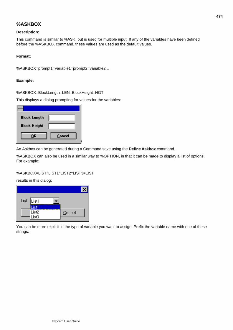
%ASKBOX
Description:
This command is similar to %ASK, but is used for multiple input. If any of the variables have been definedbefore the %ASKBOX command, these values are used as the default values.
Format:
%ASKBOX=prompt1=variable1=prompt2=variable2...
Example:
%ASKBOX=BlockLength=LEN=BlockHeight=HGT
This displays a dialog prompting for values for the variables:
An Askbox can be generated during a Command save using the Define Askbox command.
%ASKBOX can also be used in a similar way to %OPTION, in that it can be made to display a list of options.For example:
%ASKBOX=LIST^LIST1^LIST2^LIST3=LIST
results in this dialog:
You can be more explicit in the type of variable you want to assign. Prefix the variable name with one of thesestrings:
474
Edgcam User Guide
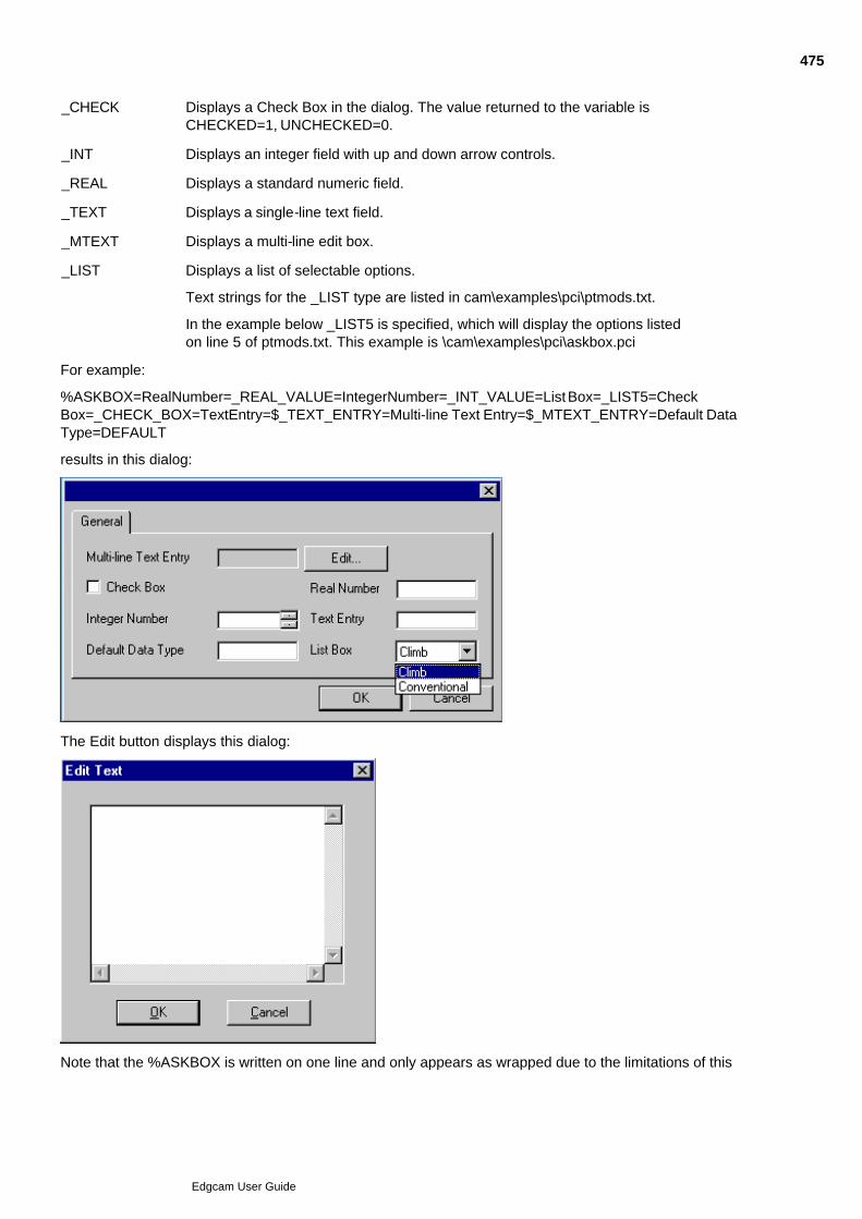
_CHECK Displays a Check Box in the dialog. The value returned to the variable isCHECKED=1, UNCHECKED=0.
_INT Displays an integer field with up and down arrow controls.
_REAL Displays a standard numeric field.
_TEXT Displays a single-line text field.
_MTEXT Displays a multi-line edit box.
_LIST Displays a list of selectable options.
Text strings for the _LIST type are listed in cam\examples\pci\ptmods.txt.
In the example below _LIST5 is specified, which will display the options listedon line 5 of ptmods.txt. This example is \cam\examples\pci\askbox.pci
For example:
%ASKBOX=RealNumber=_REAL_VALUE=IntegerNumber=_INT_VALUE=List Box=_LIST5=CheckBox=_CHECK_BOX=TextEntry=$_TEXT_ENTRY=Multi-line Text Entry=$_MTEXT_ENTRY=Default DataType=DEFAULT
results in this dialog:
The Edit button displays this dialog:
Note that the %ASKBOX is written on one line and only appears as wrapped due to the limitations of this
475
Edgcam User Guide

document.476
Edgcam User Guide
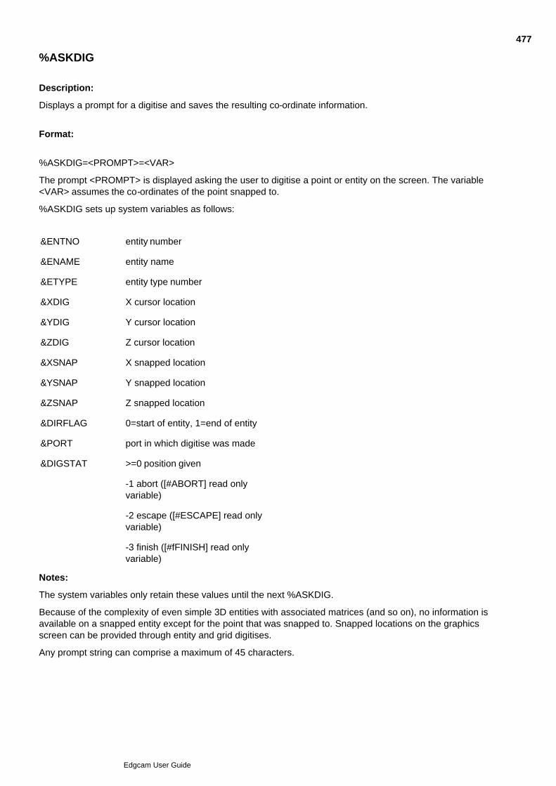
%ASKDIG
Description:
Displays a prompt for a digitise and saves the resulting co-ordinate information.
Format:
%ASKDIG=<PROMPT>=<VAR>
The prompt <PROMPT> is displayed asking the user to digitise a point or entity on the screen. The variable<VAR> assumes the co-ordinates of the point snapped to.
%ASKDIG sets up system variables as follows:
&ENTNO entity number
&ENAME entity name
&ETYPE entity type number
&XDIG X cursor location
&YDIG Y cursor location
&ZDIG Z cursor location
&XSNAP X snapped location
&YSNAP Y snapped location
&ZSNAP Z snapped location
&DIRFLAG 0=start of entity, 1=end of entity
&PORT port in which digitise was made
&DIGSTAT >=0 position given
-1 abort ([#ABORT] read onlyvariable)
-2 escape ([#ESCAPE] read onlyvariable)
-3 finish ([#fFINISH] read onlyvariable)
Notes:
The system variables only retain these values until the next %ASKDIG.
Because of the complexity of even simple 3D entities with associated matrices (and so on), no information isavailable on a snapped entity except for the point that was snapped to. Snapped locations on the graphicsscreen can be provided through entity and grid digitises.
Any prompt string can comprise a maximum of 45 characters.
477
Edgcam User Guide
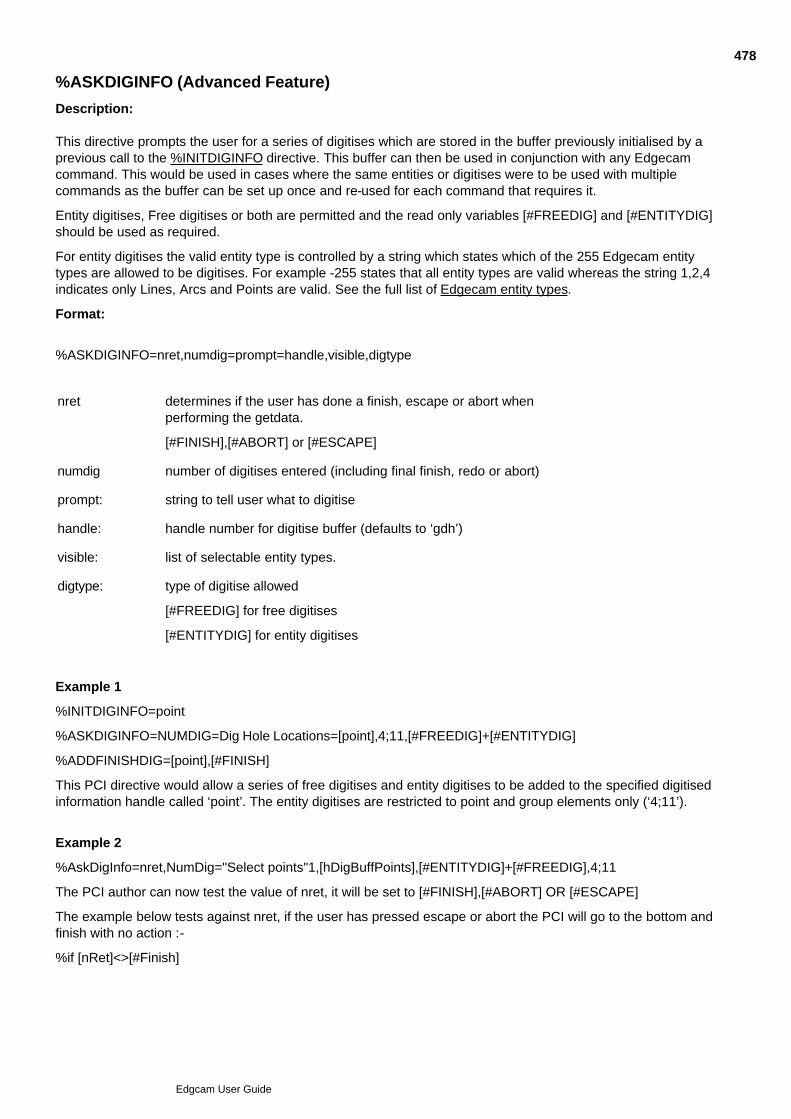
%ASKDIGINFO (Advanced Feature)
Description:
This directive prompts the user for a series of digitises which are stored in the buffer previously initialised by aprevious call to the %INITDIGINFO directive. This buffer can then be used in conjunction with any Edgecamcommand. This would be used in cases where the same entities or digitises were to be used with multiplecommands as the buffer can be set up once and re-used for each command that requires it.
Entity digitises, Free digitises or both are permitted and the read only variables [#FREEDIG] and [#ENTITYDIG]should be used as required.
For entity digitises the valid entity type is controlled by a string which states which of the 255 Edgecam entitytypes are allowed to be digitises. For example -255 states that all entity types are valid whereas the string 1,2,4indicates only Lines, Arcs and Points are valid. See the full list of Edgecam entity types.
Format:
%ASKDIGINFO=nret,numdig=prompt=handle,visible,digtype
nret determines if the user has done a finish, escape or abort whenperforming the getdata.
[#FINISH],[#ABORT] or [#ESCAPE]
numdig number of digitises entered (including final finish, redo or abort)
prompt: string to tell user what to digitise
handle: handle number for digitise buffer (defaults to ‘gdh’)
visible: list of selectable entity types.
digtype: type of digitise allowed
[#FREEDIG] for free digitises
[#ENTITYDIG] for entity digitises
Example 1
%INITDIGINFO=point
%ASKDIGINFO=NUMDIG=Dig Hole Locations=[point],4;11,[#FREEDIG]+[#ENTITYDIG]
%ADDFINISHDIG=[point],[#FINISH]
This PCI directive would allow a series of free digitises and entity digitises to be added to the specified digitisedinformation handle called ‘point’. The entity digitises are restricted to point and group elements only (‘4;11’).
Example 2
%AskDigInfo=nret,NumDig="Select points"1,[hDigBuffPoints],[#ENTITYDIG]+[#FREEDIG],4;11
The PCI author can now test the value of nret, it will be set to [#FINISH],[#ABORT] OR [#ESCAPE]
The example below tests against nret, if the user has pressed escape or abort the PCI will go to the bottom andfinish with no action :-
%if [nRet]<>[#Finish]
478
Edgcam User Guide

%FreeOperation=[OpId]
%FreeDigInfo=[hDigBuffPoints]
%GoSub=DeleteNonModalUserMods
%Goto=Bottom
479
Edgcam User Guide
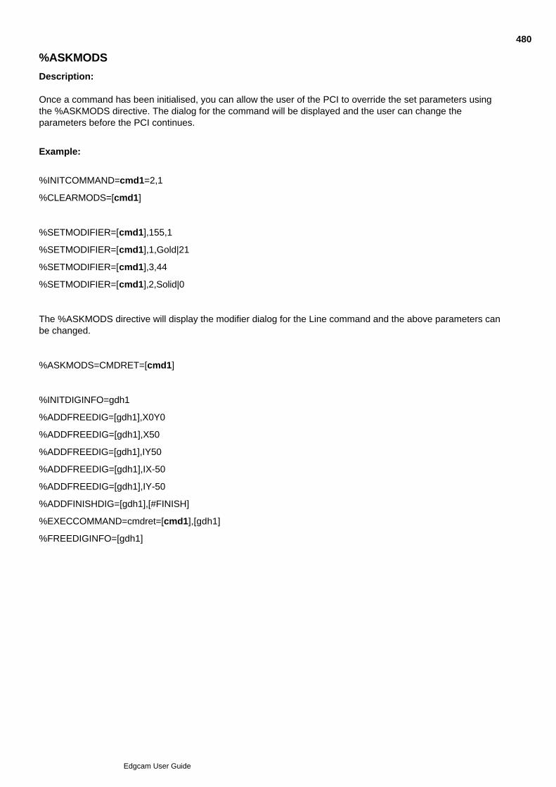
%ASKMODS
Description:
Once a command has been initialised, you can allow the user of the PCI to override the set parameters usingthe %ASKMODS directive. The dialog for the command will be displayed and the user can change theparameters before the PCI continues.
Example:
%INITCOMMAND=cmd1=2,1
%CLEARMODS=[cmd1]
%SETMODIFIER=[cmd1],155,1
%SETMODIFIER=[cmd1],1,Gold|21
%SETMODIFIER=[cmd1],3,44
%SETMODIFIER=[cmd1],2,Solid|0
The %ASKMODS directive will display the modifier dialog for the Line command and the above parameters canbe changed.
%ASKMODS=CMDRET=[cmd1]
%INITDIGINFO=gdh1
%ADDFREEDIG=[gdh1],X0Y0
%ADDFREEDIG=[gdh1],X50
%ADDFREEDIG=[gdh1],IY50
%ADDFREEDIG=[gdh1],IX-50
%ADDFREEDIG=[gdh1],IY-50
%ADDFINISHDIG=[gdh1],[#FINISH]
%EXECCOMMAND=cmdret=[cmd1],[gdh1]
%FREEDIGINFO=[gdh1]
480
Edgcam User Guide
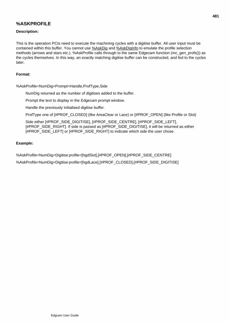
%ASKPROFILE
Description:
This is the operation PCIs need to execute the machining cycles with a digitise buffer. All user input must becontained within this buffer. You cannot use %AskDig and %AskDigInfo to emulate the profile selectionmethods (arrows and stars etc.). %AskProfile calls through to the same Edgecam function (mc_gen_profs()) asthe cycles themselves. In this way, an exactly matching digitise buffer can be constructed, and fed to the cycleslater.
Format:
%AskProfile=NumDig=Prompt=Handle,ProfType,Side
NumDig returned as the number of digitises added to the buffer.
Prompt the text to display in the Edgecam prompt window.
Handle the previously initialised digitise buffer.
ProfType one of [#PROF_CLOSED] (like AreaClear or Lace) or [#PROF_OPEN] (like Profile or Slot)
Side either [#PROF_SIDE_DIGITISE], [#PROF_SIDE_CENTRE], [#PROF_SIDE_LEFT],[#PROF_SIDE_RIGHT]. If side is passed as [#PROF_SIDE_DIGITISE], it will be returned as either[#PROF_SIDE_LEFT] or [#PROF_SIDE_RIGHT] to indicate which side the user chose.
Example:
%AskProfile=NumDig=Digitise profile=[hgdSlot],[#PROF_OPEN],[#PROF_SIDE_CENTRE]
%AskProfile=NumDig=Digitise profile=[hgdLace],[#PROF_CLOSED],[#PROF_SIDE_DIGITISE]
481
Edgcam User Guide
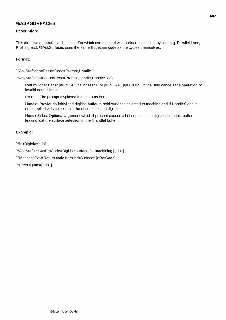
%ASKSURFACES
Description:
This directive generates a digitise buffer which can be used with surface machining cycles (e.g. Parallel Lace,Profiling etc). %AskSurfaces uses the same Edgecam code as the cycles themselves.
Format:
%AskSurfaces=ReturnCode=Prompt,Handle
%AskSurfaces=ReturnCode=Prompt,Handle,HandleSides
ReturnCode: Either [#FINISH] if successful, or [#ESCAPE]/[#ABORT] if the user cancels the operation ofinvalid data is input.
Prompt: The prompt displayed in the status bar
Handle: Previously initialised digitise buffer to hold surfaces selected to machine and if HandleSides isnot supplied will also contain the offset selection digitises
HandleSides: Optional argument which if present causes all offset selection digitises into this bufferleaving just the surface selection in the [Handle] buffer.
Example:
%InitDigInfo=gdh1
%AskSurfaces=nRetCode=Digitise surface for machining,[gdh1]
%MessageBox=Return code from AskSurfaces [nRetCode]
%FreeDigInfo=[gdh1]
482
Edgcam User Guide
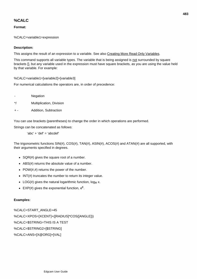
%CALC
Format:
%CALC=variable1=expression
Description:
This assigns the result of an expression to a variable. See also Creating More Read Only Variables.
This command supports all variable types. The variable that is being assigned is not surrounded by squarebrackets [], but any variable used in the expression must have square brackets, as you are using the value heldby that variable. For example:
%CALC=variable1=[variable2]+[variable3]
For numerical calculations the operators are, in order of precedence:
- Negation
*/ Multiplication, Division
+ - Addition, Subtraction
You can use brackets (parentheses) to change the order in which operations are performed.
Strings can be concatenated as follows:
‘abc’ + ‘def’ = ‘abcdef’
The trigonometric functions SIN(#), COS(#), TAN(#), ASIN(#), ACOS(#) and ATAN(#) are all supported, withtheir arguments specified in degrees.
SQR(#) gives the square root of a number.
ABS(#) returns the absolute value of a number.
POW(#,#) returns the power of the number.
INT(#) truncates the number to return its integer value.
LOG(#) gives the natural logarithmic function, loge x.
EXP(#) gives the exponential function, ex.
Examples:
%CALC=START_ANGLE=45
%CALC=XPOS=[XCENT]+([RADIUS]*COS([ANGLE]))
%CALC=$STRING=THIS IS A TEST
%CALC=$STRING2=[$STRING]
%CALC=ANS=[X@ORG]+[VAL]
483
Edgcam User Guide

Please note when using integer values in %CALC that a number followed by a decimal point - but without anumerator - is illegal (see example below).
Example
%CALC=VAR=5.0 + 2 is correct
%CALC=VAR=5 + 2 is correct
%CALC=VAR=5.+ 2 is illegal
484
Edgcam User Guide
%CHAINENTNAME
Description:
This directive chains entities from the specified entity name. The entity numbers chained are stored asseparate entity digitises in the supplied digitise buffer.
Format:
%ChainEntName=EntsChained=DigBuff,StartEnt,Direction,3DSnap,Branch
%ChainEntName=EntsChained=DigBuff,StartEnt,Direction,3DSnap,Branch,EndEnt
EntsChained: The number of entity digitises added to DigBuff
DigBuff: Digitise buffer to accept digitises for entities chained
StartEnt: Starting entity name for chain
Direction: Direction for chain, either [#DIR_FORWARD] or [#DIR_REVERSE]
3DSnap: Perform chaining in 3D? Either [#TRUE] or [#FALSE]
Branch: Check for branches? Either [#TRUE] or [#FALSE]
EndEnt: Optionally stop at this entity name if part of the chain
Example:
Select named start and end entities for a chain and smooth the entities chained.
* Wait for user to select entity to start chain
%CALC=$Empty=
%Label=StartEntity
%AskDig=Select first NAMED ENTITY for chain=Digitise
%If [&EName] = [$Empty]
%MessageBox=nRet=[#MB_ICONERROR],"Must Digitise a NAMED entity"
%GOTO=StartEntity
%Endif
%CALC=$Start=[&EName]
%CALC=ChainDir=[&DirFlag]
%Label=EndEntity
%AskDig=Select NAMED ENTITY to terminate chain=Digitise
%If [&EName] = [$Empty]
%MessageBox=nRet=[#MB_ICONERROR],"Must Digitise a NAMED entity"
%GOTO=StartEntity
%Endif
485
Edgcam User Guide

* Chain entities storing in buffer
%InitDigInfo=gdh1
%ChainEntName=nEnts=[gdh1],[$Start],[ChainDir],[#TRUE],[#FALSE],[&EName]
%MessageBox=[nEnts] selected by chain
%AddFinishDig=[gdh1],[#FINISH]
* Create a smoothed continuous through the entities chained
%InitCommand=cmd1=2,56
%SetModifier=[cmd1],56,0.01
%SetModifier=[cmd1],43,1
%ExecCommand=cmdret=[cmd1],[gdh1]
%FreeDigInfo=[gdh1]
See Also: %ChainEntNo
486
Edgcam User Guide
%CHAINENTNO
Description:
This directive chains entities from the specified entity number. The entity numbers chained are stored asseparate entity digitises in the supplied digitise buffer.
Format:
%ChainEntno=EntsChained=DigBuff,StartEnt,Direction,3DSnap,Branch
%ChainEntno=EntsChained=DigBuff,StartEnt,Direction,3DSnap,Branch,EndEnt
EntsChained: The number of entity digitises added to DigBuff
DigBuff: Digitise buffer to accept digitises for entities chained
StartEnt: Starting entity number for chain.
Direction: Direction for chain, either [#DIR_FORWARD] or [#DIR_REVERSE]
3DSnap: Perform chaining in 3D? Either [#TRUE] or [#FALSE]
Branch: Check for branches? Either [#TRUE] or [#FALSE]
EndEnt: Optionally stop at this entity number if part of the chain
Example:
Chain entities, change their colour to Lime Green and verify the changes.
* Wait for user to select entity to start chain%Label=EntityRequired%AskDig=Select first ENTITY for chain=Digitise%If [&Entno] <= 0%MessageBox=nRet=[#MB_ICONERROR],"Must Digitise an entity"%GOTO=EntityRequired%Endif* Chain entities storing in buffer%InitDigInfo=gdh1%ChainEntno=nEnts=[gdh1],[&Entno],[&DirFlag],[#TRUE],[#FALSE]%MessageBox=[nEnts] selected by chain%AddFinishDig=[gdh1],[#FINISH]* Change colour of entities to Lime Green (14)%InitCommand=cmd1=1,1%SetModifier=[cmd1],1,14|14%ExecCommand=cmdret=[cmd1],[gdh1]* Verify entities chained%InitCommand=cmdh=17,69%ExecCommand=ret=[cmdh],[gdh1]%FreeDigInfo=[gdh1]
See Also: %ChainEntName
487
Edgcam User Guide

%CLEARMODS
Description:
Clear all Edgecam modifier values for previously initialised command.
Format:
%CLEARMODS=handle
handle: handle number for the command
Example:
%CLEARMODS=[cmdh]
488
Edgcam User Guide

%COMMITOPERATION
Description:
This directive commits the operation to the Edgecam database and creates a machining command in theinstruction list. Subsequent Machining instructions generated by the PCI are created as child instructions forthe operation. These are displayed with the '***' prefix in the instruction list.
Format:
%CommitOperation=OperationID
%CommitOperation=OperationID,DigBuff1^DigBuff2^&ldots;
OperationID: The ID returned by %InitOperation
DigBuff: Digitise buffer to be added to the operation. Each digitise buffer is added using the ^ separator.No digitise buffers have to be supplied if the operation does not require user interaction. The digitisebuffers supplied are added together and used when regenerating the operation.
489
Edgcam User Guide
%COPYMODIFIERS
Description:
To copy similar modifiers from one command to another (similar is defined as having the same number andtype).
Format:
%CopyModifiers=SrcCmd,DestCmd,ListOfModifiers
SrcCmd: the handle of the command from which to copy the modifiers.
DestCmd: the handle of the command into which to copy the modifiers.
ListOfModifers: an optional parameter. It can be a caret-separated list of those modifiers that you wishto copy. If not supplied, all similar modifiers are copied.
Examples:
For example, in the Pocket operation, the roughing cycle can either be AreaClear or Lace. Nearly all themodifiers in the operation are common between these two cycles (Stepover, Cut Increment, Depth parametersetc.). The most efficient way to implement this would be to add command modifiers from one of the twocommands (say Lace), and if the user chooses AreaClear, then copy over the modifiers from the Lacecommand to the AreaClear command.
%CopyModifiers=[cmdLace],[cmdAreaClear]
This would copy over all similar modifiers from one command to the other.
%CopyModifiers=[cmdLace],[cmdAreaClear],28^29^161^9
This would copy the depth modifiers (Clearance, Retract, Level and Depth) from one command to the other.
490
Edgcam User Guide

%DEBUG
Description:
This selects the level of debug, allowing you to view the substituted and unsubstituted version of each line ofthe parametric as it is run.
Format:
%DEBUG=<d/s><0/1>
Debug messages can be output to:
Screen only (%DEBUG=s)
Disk File only (%DEBUG=d)
Screen and Disk File (%DEBUG=ds).
When output to a disk file, the file PT_DEBUG.TXT is created in the system temporary file location. Control thelevel of debug by adding 0 or 1 to the end of the statement:
%DEBUG=0 debug off
%DEBUG=1 debug on all lines
When debug text is output to the screen, any lines longer than 78 characters are truncated.
Example:
%DEBUG=ds1
%DEBUG=0
%DEBUG=s1
491
Edgcam User Guide

%DELETE
The %DELETE directive deletes the specified variable name. This directive is usually placed at the beginningor the end of a PCI file. Note that all variables continue to exist until the PCI stops running.
Format:
%DELETE=variable
Examples:
%DELETE=$TEXT
%DELETE=COUNT
492
Edgcam User Guide

%DELETE_ALL_VARS
The %DELETE_ALL_VARS directive deletes all currently defined variables. This directive is typically used atthe beginning or the end of a PCI file to delete all currently defined variables. Note that all variables continue toexist until the PCI stops running.
Format:
%DELETE_ALL_VARS
493
Edgcam User Guide

%DISPLAY
Description:
Allows text to be displayed on screen. Multi line text is supported by delimiting each line with the ‘\’ character.Note that %MESSAGEBOX can also display text in a dialog without the need to have a trailing \ on themessage.
If a single line display is used, the text appears on the status bar and processing continues. You should notexceed 80 characters per display line.
If the Feedback Dialog option on the General tab of the Preferences (Options menu) dialog is checked multiline %Display text is sent to a dialog box and must be dismissed by the user before further processing of thePCI takes place. If this preference is not checked the text is displayed in the feedback window and processingcontinues without user acknowledgement.
Format:
%DISPLAY=<text to be displayed>
Examples:
Single line text
%DISPLAY=The value of the calculation is: [VAR]
If the value of [VAR] is 75 then the following text would be displayed
The value of the calculation is: 75
Note: the text for a single line display is displayed on the status bar, not in a dialog.
Multiple line text
%DISPLAY=Option 1\Option 2\Option 3
This would display the following in a dialog box:
Option 1
Option 2
Option 3
494
Edgcam User Guide

%DOOPERATIONMODS
Description:
Prompts the user to enter values for the modifiers. A standard Windows dialog is presented containing themodifiers as specified by the %ADDCMDMODTOOPERATION directives.
If the user completes the dialog and selects ‘OK’ , cmdRet is assigned the value #FINISH. If the user selects‘Cancel’ #ESCAPE is assigned.
A standard Edgecam dialog is displayed, containing each modifier as specified by the%ADDCMDMODTOOPERATION and %ADDUSERMODTOOPERATION directives.
Format:
%DOOPERATIONMODS=cmdRet=[OperationId]
495
Edgcam User Guide

%END
Description:
To terminate PCI processing. This is typically used before subroutine definition or in an error condition.
Note that if %END is executed in a %INCLUDE file, the entire PCI is terminated.
Format:
%END=[#FINISH]
%END
If no parameter is given then [#FINISH] is assumed.
%END=[#ESCAPE]
%END=[#ABORT]
See Also: %GOSUB.
496
Edgcam User Guide

%ENDIF
Description:
To signify the end of a multiple %IF statement.
Format:
%ENDIF
Example:
%IF [FRED]=5
%CALC=BILL=[FRED]+6
%IF [BILL]>10
%GOTO=LABEL2
%ENDIF
%GOTO=LABEL3
%ENDIF
497
Edgcam User Guide
%ERROR
Description:
To enable/disable the display of warning messages on the screen.
Format:
%ERROR=#
If %ERROR is set to 1 then any warning messages will be displayed on the screen (this is the default action).This option can be used to re-instate the display of messages on the screen.
If %ERROR is set to 0 then any warning messages will NOT be displayed on the screen. This option allows aparametric to continue, skipping over a message that would be displayed on the screen (thereby halting thePCI until the detection of a keypress).
Example:
In this example a ‘zero length line’ warning message would be displayed by default. However, no warningmessages will be displayed because %ERROR has been set to zero.
%ERROR=0
* Initialising command:- Line
%INITCOMMAND=cmdh=2,1
%CLEARMODS=[cmdh]
* Setting modifier 'Colour'
%SETMODIFIER=[cmdh],1,Green|1
* Setting modifier 'Layer'
%SETMODIFIER=[cmdh],3,1
* Setting modifier 'Style'
%SETMODIFIER=[cmdh],2,Solid|0
%INITDIGINFO=gdh
* Add Free dig to Digitised input data
%ADDFREEDIG=[gdh1],X-85.77Y28.655
* Add Free dig to Digitised input data
%ADDFREEDIG=[gdh1],X10.9162Y-49.7076
* Add Entity to Digitised input via its number 3DSnap NO Direction Reverse
%ADDENTNODIG=[gdh1],[&BASEENT]+1,0,1
* Add Entity to Digitised input via its number 3DSnap NO Direction Reverse
%ADDENTNODIG=[gdh1],[&BASEENT]+1,0,1
* Finish Digitised input
%ADDFINISHDIG=[gdh1],[#FINISH]
%EXECCOMMAND=cmdret=[cmdh],[gdh1]
%FREEDIGINFO=[gdh1]
498
Edgcam User Guide
%EXECCOMMAND
Description:
This directive executes the previously initialised command (using %INITCOMMAND) with the modifiers andsub-modifiers as defined by the user.
The %EXECCOMMAND includes context checking to prevent Edgecam commands being used with invalidtooling. Additionally, the %EXECCOMMAND completes the initialisation of the command.
Format:
%EXECCOMMAND=retval=handle,getdata_vmh
retval: return value from executed command
Handle: handle number for command
Getdata_vmh: optional getdata buffer
Example:
%EXECCOMMAND=cmdret=[cmdh],[gdh1]
Multiple digitise buffers may be used when executing a command
In some instances it is useful to add together digitise buffers, before passing a single handle to%INITCOMMAND. Typically this helps when dealing with islands with the geometry from each island held in adigitise buffer.
%EXECCOMMAND optionally takes additional digitise buffers in its arguments, as shown below.
%EXECCOMMAND=[cmdProfile],[gdOuterProf]^[#FINISH]^[gdIsland]^...
A variable number of digitise buffers are supported by this method.
The read only variables #FINISH, #REDO, and #ABORT may be used directly to complete the specification ofdigitised information.
499
Edgcam User Guide

%FREECOMMAND
Description:
This directive frees all storage associated with a previously initialised command. This is only used if thecommand is not executed since the %EXECCOMMAND automatically frees any storage used.
Format:
%FREECOMMAND=handle
handle: handle number for the command
500
Edgcam User Guide

%FREEDIGINFO
Description:
This directive closes the (previously initialised) digitised information buffer. This must be carried out for eachoccurrence of %INITDIGINFO, since %EXECCOMMAND does not release storage allocated by this buffer.
Note that you may want to retain the digitised information held in the buffer (to use data in another command).You can do this by changing the name of the handle on the %INITDIGINFO (and associated data) to a uniquename and only execute the %FREEDIGINFO=uniquename once you have finished with the data.
An example of this is in the involute.pci file. This can be found in the edge\cam\examples\pci directory.
Format:
%FREEDIGINFO=handle
handle: number for the digitise buffer
Example:
FREEDIGINFO=[gdh1]
501
Edgcam User Guide

%FREEMESSAGESTRING
Description
This PCI directive frees a message string previously initialised by %INITMESSAGESTRING.
Format:
%FreeMessageString=MessageHandle
MessageHandle: Handle number returned by %INITMESSAGESTRING
Example:
%FreeMessageString=[strMessage]
See Also: %AddMessageString, %InitMessageString, %MessageBox
502
Edgcam User Guide

%FREEOPERATION
Description:
Frees memory used by the PCI operation.
Format:
%FREEOPERATION=OperationId
503
Edgcam User Guide
%GETMODIFIER
Description:
This directive has to used in conjunction with %AddCmdModToOperation.
Format:
%GetModifier=variableset=[command handle],modifier number,variable name to store returned value
Example:
In the example below bSet is 1 when a value is returned for tool diameter or 0 when no value is returned, and_realtooldiam is used to store the returned diameter value.
* Diameter
%AddCmdModToOperation=[OpId],[cmdTool],47,^"Tooling"17
%AddCallBackReference=[OpId],tsFinish,[#IndexDiameter],[cmdTool],[#ModDiameter]
*
%Label=DoOpMods
*
%DoOperationMods=nOpRet=[OpId]
%GetModifier=bSet=[cmdtool],47,_realtooldiam
See Also: %COPYMODIFIERS.
504
Edgcam User Guide

%GOSUB
Description:
Processing jumps to the line specified by a label, until a %RETURN statement is encountered, at which pointprocessing resumes at the statement following the %GOSUB.
Subroutines may be nested.
Format:
%GOSUB=label
Example:
%ASK=ANGLE IN DEGREES? =DEG
%GOSUB=DEG_TO_RAD
%DISPLAY=ANGLE IN RADIANS IS [RAD]
%END
%LABEL=DEG_TO_RAD
%CALC=RAD=[DEG]*3.14159/180
%RETURN
This example prompts for an angle in degrees and then displays that value in radians. The calculations arecarried out in a subroutine.
505
Edgcam User Guide

%GOTO
Description:
Processing jumps to a line specified by a label.
Using this command, a loop may be created to execute a portion of the parametric file several times, to jumpover a section of code, or to jump out of another loop. Note that you can create an infinite loop if there is noend condition, or if the end condition is not met.
Format:
%GOTO=label
Example:
%GOTO=JUMP
...
...
%LABEL=JUMP
506
Edgcam User Guide
%IF
Description:
If the result of the comparison between variable1 and variable2 is true, then processing jumps to the linespecified by a label.
Format:
%IF variable1 operator variable2 %GOTO=label
The variables may be of any type, but numeric and string variables may not be mixed.
Operators supported are:
<> not equal to
<= less than or equal to
>= greater than or equal to
< less than
> greater than
= equal to
Example 1:
%IF [COUNT]<10 %GOTO=REPEAT
%IF [COUNT]>[NUMBER] %GOTO=END
%IF [$STRING]=Q %GOTO=STOP
Note that single-line IF statements only work with %GOTO statements.
Example 2:
%IF [COUNT]=[NUMBER]
%CALC=[NUMBER]*2
%ENDIF
Multiple statements are also permitted, in which case an %ENDIF is used to signify the end of the conditionalstatement. Nested %IF statements are valid.
Example 3:
%IF [COUNT]=5
%CALC=NUMBER=[COUNT]+6
%IF [NUMBER]>10
%GOTO=LABEL2
507
Edgcam User Guide

%ENDIF
%GOTO=LABEL3
%ENDIF
Indentation may be used as above to aid readability, but you can only use tabs.
508
Edgcam User Guide
%INCLUDE
Description:
Calls an existing PCI from within another PCI.
Format:
%INCLUDE=path
path: Directory location and filename (variables may be used)
Note that any variables used in the %INCLUDE string must be defined before PCI execution.
Example:
%CALC=$PATH=c:\tmp
%INCLUDE=[$PATH]\test.pci
... where $PATH has previously been assigned a value, for example ‘c:\Edgecam\examples’.
509
Edgcam User Guide
%INITCOMMAND
Description:
This directive initialises a command from within a PCI. Each call of this directive returns a handle, which is aunique reference to that instance of the command and is required with all subsequent references to it. Thevariable ‘cmd1’ is the default for a command handle.
Format:
%INITCOMMAND=handle=verb,noun
handle: returned handle number for command
verb: Verb number for command
noun: Noun number for command
Example:
%INITCOMMAND=cmd1=2,1
This would set up a handle for the GEOMETRY LINE command.
Turn off context checking when initialising a command
The PCI directive %INITCOMMAND needs valid tooling to be selected for the command being initialised.Normally this works well, but when building up a PCI operation, the tooling is unlikely to have been pre-selectedsince the tooling is an integral part of the operation.
The %INITCOMMAND has an optional additional parameter to turn off the context checking when initialising acommand:
%INITCOMMAND=cmdFaceMill=102,4,[#FALSE]
This will initialise the Edgecam command with no checking for the validity of the selected tool.
510
Edgcam User Guide

%INITDIGINFO
Description:
Initialises storage space for digitised information. When command save is used the variable ‘gdh1’ is alwaysused to reference this storage.
Format:
%INITDIGINFO=handle
handle: name of the digitise buffer
Example:
%INITDIGINFO=gdh1
511
Edgcam User Guide

%INITMESSAGESTRING
Description:
This PCI directive initialises a message string and sets up a handle used to identify it. A message string is a listof text strings each of which is shown on a separate line when displayed using %MESSAGEBOX.
Format:
%InitMessageString=MessageHandle
MessageHandle: Returned handle number used to access message string
Example:
%InitMessageString=strMessage
When a message list is no longer required it can be freed by using %FREEMESSAGESTRING. When a PCIterminates all message strings still defined are automatically freed.
See Also: %AddMessageString, %FreeMessageString, %MessageBox
512
Edgcam User Guide

%INITOPERATION
Description:
This initialises a new Edgecam operation. A variable name is defined and this is used as reference to theoperation in subsequent steps. A name for this operation is also given.
Format:
%INITOPERATION=PCI variable=operation name,help file name,help context id
Example:
%INITOPERATION=OperationId=Rough Face Mill,EdgeOp.hlp,10021
OperationId: the PCI variable used to identify the operation.
“Rough Face Mill”: the textual name of the operation. This string is also used as the title of theoperation dialog when displayed to the user, and for the name of the operation displayed in theEdgecam operations list.
EdgeOp.hlp: the name of the help file to be used to display context sensitive help. This will be locatedin the appropriate ‘language’ directory or subdirectory.
10021: the help context id for this command.
The help file name and the context Id are optional parameters.
513
Edgcam User Guide

%ISTOOLSAME
Description:
The Toolchange command should only be executed if the current tool is different from the new one.%ISTOOLSAME compares the tool defined in a toolchange command handle with the currently selected tool.
Format:
%IsToolSame=Result=CommandHandle
Result: a variable in which the result will be placed. The result will be either #TRUE or #FALSE.
CommandHandle: the handle to the toolchange command about to be executed.
Example:
%IsToolSame=bToolSame=[cmdMillCutter]
%If [bToolSame]=[#FALSE]
%ExecCommand=cmdret=[cmdMillCutter],[hDigBuffEmpty]
%EndIf
514
Edgcam User Guide

%ISVARDEFINED
Description:
If a PCI accesses an undefined variable (using a %Calc directive for instance), an error message is displayed.It can be useful to check if a variable exists without causing an error. It is also essential to be able to tell if aUser Modifier has had its value set by the user. %ISVARDEFINED lets you check if a variable has beendefined.
Format:
%IsVarDefined=Exists=Variable
Exists: a variable that will be set to [#True] or [#False].
Variable: the subject of the test.
Example:
%IsVarDefined=bExists=_realDepth
%If [bExists]<>[#True]
%MessageBox=Depth must be specified
%Endif
515
Edgcam User Guide

%LABEL
Description:
This is the destination of a %GOTO or %GOSUB statement.
Format:
%LABEL=label
Example:
%IF[VAR]=1%GOTO=END
. .
. .
%LABEL=END
516
Edgcam User Guide

%LEN
Description:
The length of a string is loaded into a numeric variable.
Format:
%LEN=variable=string
Example:
%LEN=LENGTH=ABCDEF
The string ‘ABCDEF’ is six characters long, so the directive assigns a value of ‘6’ to the numeric variableLENGTH.
517
Edgcam User Guide
%LOADTOOL
Description
Loads tools from the currently selected ToolStore.
Example
%LoadTool=[cmd1],10mm Slot Drill - 2 Flute - 13A F30m
To use this directive in a PCI the following sequence of commands is suggested:
* Initialising command:- Milling Cutter
%InitCommand=cmd1=36,108
* Clear the command modifiers
%ClearMods=[cmd1]
* Load required tool from ToolStore
%LoadTool=[cmd1],10mm Slot Drill - 2 Flute - 13A F30m
* Present dialog for interactive input (Optional)
%AskMods=cmdret=[cmd1]
* Check command completed
%if [cmdret]<>[#FINISH]
%FreeCommand=[cmd1]
%endif
* Execute command	
%if [cmdret]=[#FINISH]
%InitDigInfo=gdh1
%ExecCommand=cmdret=[cmd1],[gdh1]
%FreeDigInfo=[gdh1]
%endif
Note that if an attempt is made to load a non-existent tool, no data will be placed in the dialog. This will betrapped by the system at run time as it expects at least a diameter to be specified for each tool and a warningto the effect that no diameter has been set will be given.
If no dialog is to be presented for user input then the %ASKMODS line, above, should be omitted.
518
Edgcam User Guide
%MESSAGEBOX
Description:
Although you can use the %DISPLAY directive to display a Windows message box, for compatibility with DOSa fixed-width font is used. A better look can be achieved by using %MESSAGEBOX since it uses aproportionally spaced font. Read-only variables are supplied to define the message-box styles.
There are two forms of this directive, a shortened version which just displays the message with an OK buttonand the full version which allows the style to be configured and the return code from the box to be determined.The shortened version is an alternative to %DISPLAY.
Format:
%MessageBox=Message
%MessageBox=ReturnCode=Style,Message
ReturnCode
Indicates the button pressed to exit the message box. This can be one of the following constants:
[#MB_RET_OK] OK button was pressed
[#MB_RET_CANCEL] Cancel button was pressed
[#MB_RET_YES] Yes button was pressed
[#MB_RET_NO] No button was pressed
Style
Controls the Icon and buttons displayed on the message box. The button style and icon style can be specifiedby using a + between them. Button styles are:
[#MB_OK] OK button is displayed
[#MB_OKCANCEL] OK and Cancel button are displayed
[#MB_YESNOCANCEL] Yes, No and Cancel buttons are displayed
[#MB_YESNO] Yes and No buttons are displayed
[#MB_ICONERROR] Message box has error (x) icon
[#MB_ICONINFORMATION] Message box has information (i) icon
[#MB_ICONQUESTION] Message box has question (?) icon
[#MB_ICONWARNING] Message box has warning (!) icon
[#MB_DEFBUTTON2] Second button is default
[#MB_DEFBUTTON3] Third button is default
[#MB_NODEFBUTTON] No button is default
[#MB_RIGHT] Message is right justified
Examples
519
Edgcam User Guide
%MESSAGELISTBOX
Description:
This directive is an alternative to %OPTION directive. Instead of buttons the options are displayed in a listbox.The return value is the option selected (first option is 1) unless Cancel is pressed when –1 is returned. Thedefault value determines which item is initially selected when the listbox is displayed.
Format:
%MessageListBox=Selection=DefaultOption,Title,Option1^Option2^Option3
Selection: Indicates the option selected (1, 2, 3 &ldots;) or –1 if Cancel was pressed.
DefaultOption: Determines which option is initially selected (1, 2, 3...). If this is not a valid option numberthe last option is selected.
Title: This is the title for the ListBox
Option1^&ldots;: The list of options, each one separated by ^. Note: The options cannot contain
commas.
Example:
Display a list of three choices (second choice is the default), and report user selection. The same sample isalso shown using message strings
* Listbox with second option defaulted
%MessageListBox=nRet=2,Select an Option,Option1^Option2^Option3
%MessageBox=Selected option : [nRet]
* Use Message Strings
%InitMessageString=strOptions
%Calc=Option=0
%Label=OptionLoop
%Calc=Option=[Option]+1
%AddMessageString=[strOptions]=Option[Option]
%If [Option] < 3 %GotoOptionLoop
%MessageListBox=nRet=2,Select an Option,[strOptions]
%MessageBox=Selected option : [nRet]
%FreeMessageString=[strOptions]
520
Edgcam User Guide
%MID
Description:
This stores part of one string variable as another. That is, part of string2 is loaded into the string1 variable (seethe format and example below). The starting character and the length of the part are also defined.
Format:
%MID=string1=string2,start,length
length must be 252 or less
Example 1:
%MID=$SUBSTR=[$STRING],3,2
Example 2:
%MID=$STRING=ABCDEF,3,2
This second example would define $STRING as CD.
521
Edgcam User Guide
%OPTION
Description:
To prompt the user to select one of a list of options and assign that option to a variable.
Format:
%OPTION=prompt^option1^option2^option3=variable
An %OPTION directive line can be a maximum of 128 characters long. The prompt string can be a maximum of45 characters long.
Note that %ASK can perform a similar function.
Example:
%label=page1
%OPTION=PAGE1^PAGE2^PAGE3^PAGE4^END=PAGE
%if[page]=1%goto=Page2
%if[page]=2%goto=Page3
%if[page]=3%goto=Page4
%if[page]=4
%end
%endif
%label=page2
%option=Page2^page1^page2^page3^page4^end=page
%if[page]=1%goto=page1
%if[page]=2%goto=page2
%if[page]=3%goto=page3
%if[page]=4%goto=page4
%if[page]=5
%end
%endif
...
(etc.)
This produces an option box from which only one option can be chosen. The selected option is then assignedto the variable PAGE. The first option sets PAGE=1, the second sets PAGE=2 and so on. The value of PAGEcan be used with %IF statements to determine the program flow (see below)
522
Edgcam User Guide
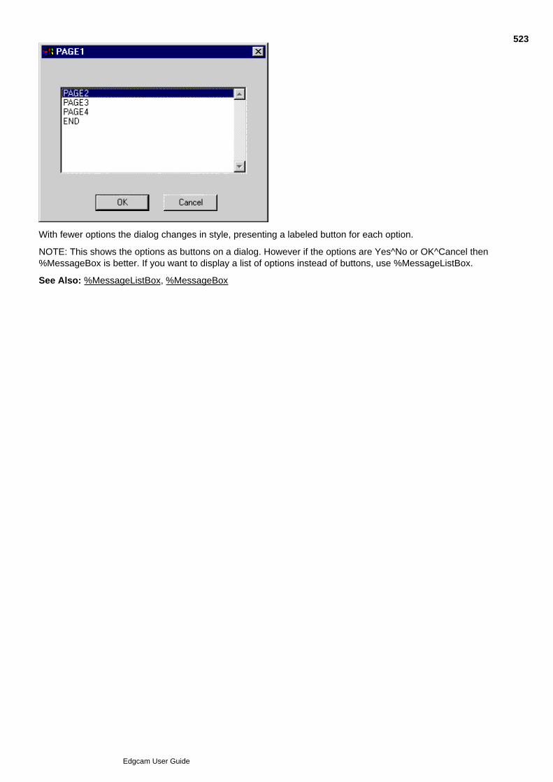
With fewer options the dialog changes in style, presenting a labeled button for each option.
NOTE: This shows the options as buttons on a dialog. However if the options are Yes^No or OK^Cancel then%MessageBox is better. If you want to display a list of options instead of buttons, use %MessageListBox.
See Also: %MessageListBox, %MessageBox
523
Edgcam User Guide
%PADTEXT
Description:
To justify the text string relative to the position defined, and "pad" the entire string to the specified length.
Format:
%PADTEXT=variable1=string,justification,length
string Text string
justification 0 = Left, 1 = Right, 2 = Centre
length specifies the total number of characters in the string
Example:
%PADTEXT=$STR1=1234,0,10
%PADTEXT=$STR2=1234,1,10
%PADTEXT=$STR3=1234,2,10
*
%MessageBox=1 *[$STR1]*\2 *[$STR2]*\3 *[$STR3]*
The text for this example appears as follows (with spaces shown as "-"):
1 *1234------*
2 *------1234*
3 *---1234---*
524
Edgcam User Guide
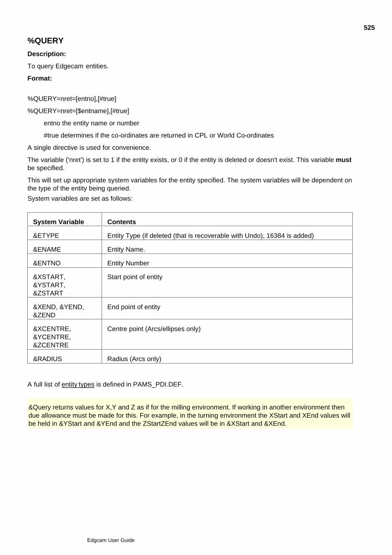
%QUERY
Description:
To query Edgecam entities.
Format:
%QUERY=nret=[entno],[#true]
%QUERY=nret=[$entname],[#true]
entno the entity name or number
#true determines if the co-ordinates are returned in CPL or World Co-ordinates
A single directive is used for convenience.
The variable ('nret') is set to 1 if the entity exists, or 0 if the entity is deleted or doesn't exist. This variable mustbe specified.
This will set up appropriate system variables for the entity specified. The system variables will be dependent onthe type of the entity being queried.
System variables are set as follows:
System Variable Contents
&ETYPE Entity Type (if deleted (that is recoverable with Undo), 16384 is added)
&ENAME Entity Name.
&ENTNO Entity Number
&XSTART,&YSTART,&ZSTART
Start point of entity
&XEND, &YEND,&ZEND
End point of entity
&XCENTRE,&YCENTRE,&ZCENTRE
Centre point (Arcs/ellipses only)
&RADIUS Radius (Arcs only)
A full list of entity types is defined in PAMS_PDI.DEF.
&Query returns values for X,Y and Z as if for the milling environment. If working in another environment thendue allowance must be made for this. For example, in the turning environment the XStart and XEnd values willbe held in &YStart and &YEnd and the ZStartZEnd values will be in &XStart and &XEnd.
525
Edgcam User Guide
%QUERYDIGINFO
Description:
To allow the PCI to query the contents of a digitise buffer.
Format:
%QUERYDIGINFO=nret=[gdh],[ElementNumber]
The directive needs a specified digitise buffer [gdh] and element number.
Once executed the appropriate system variables are updated with the entities information.
The variable ('nret') is set to 0 if the entity is deleted, or 1 if the entity is not deleted. This variable must bespecified.
See PCI System Variables
Entity Name digitises are returned as DIG_ENTNODIG for the type (the name can be retrieved from therelevant system variable).
Free digitise locations specified by co-ordinate strings are returned as DIG_LOCATION for the type. The co-ordinate string is not accessible.
For free digitises, the X, Y and Z locations are set up in the system variables &XDIG, &YDIG and &ZDIGrespectively.
For world and view digitises, &XDIG, &YDIG and &ZDIG contain the world and view co-ordinates respectively.
For port digitises, the port number is set up in the system variable &PORT.
No other system variables are set up for the other digitise types (DIG_SCREEN, DIG_UVSURF,DIG_ELEMENT, DIG_CONSTRUCT_REF and DIG_COMPENENT_INFO).
For entity digitises, the information set up is as for the %QUERY directive.
All information is set up in the co-ordinate system of the current CPL.
Example
526
Edgcam User Guide

%REINITCOMMAND
Description:
A command can be initialised “out of context”, that is without the normal checks to see if it is valid to executethe command at that time. In bypassing the context checking, a number of actions that normal take placeduring command initialisation are also bypassed. Modal values are not loaded, and modifiers from the codegenerator are not added. In certain cases, these must be accessed before the command is executed, so use%REINITCOMMAND to re-initialise a command that has been initialised out of context.
Format:
%ReInitCommand=CommandHandle
CommandHandle is the handle of the command to be re-initialised
Example:
%ReInitCommand=[cmdHole]
527
Edgcam User Guide
%RESPONSE
Format:
%RESPONSE=value
Description:
There are a number of places in Edgecam which require confirmation from the user before a certain action iscarried out. There are three cases to consider:
Overwriting an existing data file. An example of this is saving a file over one which already exists.
Overwriting an existing part file by loading a new data file.
Exceptional circumstances, such as printer off line require a retry option box to be offered to the printer.
This directive gives a mechanism to prevent Edgecam from offering an option box, thereby halting the PCIapplication to wait for user input. The %RESPONSE settings are:
%RESPONSE=0 System processes all system confirmation boxes and asks user forconfirmation. This is the default value.
%RESPONSE=1 System ignores all file overwrite confirmation requests, assuming apositive response.
Option boxes presented to the user in exceptional circumstances only (such as printer off line) always pauseand prompt the user for input. No method is offered for automatically forcing a negative response.
528
Edgcam User Guide

%RETURN
Description:
Used at the end of a subroutine to return processing to the line following the last %GOSUB statement.
Format:
%RETURN
Example:
See %GOSUB.
529
Edgcam User Guide

%SETCALLBACK
Description:
Sets up the ToolStore to be ready to return values into modifiers contained in the PCI.
Example:
%SetCallBack=tsFinish=[OpId],[cmdToolFinish],[#ModToolStore]
This command is intended for use with ToolStore toolchanges and will usually be used together with%ADDCALLBACKREF. Click here to see an example.
530
Edgcam User Guide

%SETFEATUREVARS
Description:
Assigns feature attribute values to PCI variables.
To see the assigned values, use the PCI variables window (use Right-Click menu Refresh once in thewindow). Note that some feature attributes are not available as PCI variables.
This variable names shown in the window are the actual ones you need to use in PCI directives, such as'~Diameter~', for Hole features.
This needs to be called before you create modifiers that use the variables, to be added to the operation dialog(using AddUserModToOperation, AddCmdModToOperation and so on).
If more than one such feature is digitised, then only the attributes values common to all the features are set.For example, if the diameter of a number of holes is the same then the ~diameter is set, but if they havedifferent depths then ~depth will not be set. Format %SetFeatureVars=handle
handle: returned handle number for command
Please Note
You can use the directive without the handle to clear the variables, after use.
Only certain features support this mechanism:- Mill features found in Edgecam Version 9.0 (unless theyare superseded), Hole features found in Edgecam 10.0 or earlier and Turn features. For other features,use Strategy Manager to allow operations to access feature attributes, rather than PCIs.
The behaviour of the PCI variables set by %SetFeatureVars will not be guaranteed in any PCIs that usethem (apart from the Edgecam operations); they may unintentionally become incompatible.
531
Edgcam User Guide

%SETMODIFIER
Description:
This directive sets the value for an Edgecam modifier.
Format:
%SETMODIFIER=handle,modifier #,modifier text|value
handle Handle number for command
modifier # Modifier number to set
modifier text Text associated to the modifier value
value Modifier value
Example:
%SETMODIFIER=[cmdh],1,Blue|2
532
Edgcam User Guide
%SETPACKAGE
Description:
To switch Edgecam between Design and Manufacture.
Format:
%SETPACKAGE=value
The %SETPACKAGE settings are:
0 = Design
1 = Manufacture
Example:
When moving to manufacture and initialising a new sequence the PCI currently assumes the machiningsequence values follow immediately afterwards in the PCI as shown in the example below:
%SETPACKAGE=1
* Initialising command:- Machining Sequence
%INITCOMMAND=cmd=2,90
%SETMODIFIER=[cmd],105,Mill|1
%SETMODIFIER=[cmd],102,rotary.mcp
%SETMODIFIER=[cmd],244,[&TOP]
%SETMODIFIER=[cmd],212,Incremental|0
%EXECCOMMAND=cmdret=[cmd],-1
If the machining sequence information is not present in the PCI or a sequence already available, the PCI willfail.
533
Edgcam User Guide
%TOOLBARMODS
Description:
This directive allows a PCI program to use the toolbar controls for colour, layer and style.
Format:
%TOOLBARMODS=toolbarmods
toolbarmods: Controls where the PCI obtains colour, layer and style information:
0=Use embedded values in PCI,1=Use current values from the toolbar.
By default, the PCI uses any values for these parameters that have been embedded in the PCI program.
Example:
%TOOLBARMODS=1
This allows the PCI to use the current toolbar values.
534
Edgcam User Guide

%WAIT
Description:
Inserts a pause of the specified number of seconds. Pressing function key 8 stops the pause and aborts theparametric.
Format:
%WAIT=time
Example:
%WAIT=20
This causes the program to pause for 20 seconds before continuing.
535
Edgcam User Guide
PCI System Variables
Note that the real number PCI system variables (for example &XSTART and &SYSTOL) are evaluated in PCIsto 9 significant figures.
General
&BASEENT This system variable is set to the last entity number in a new worksession orloaded part. This allows the creation of new entities to be generated andreferenced to the variable, instead of to an actual entity number which couldbe different between worksessions and loaded parts.
For further details on the following system variables refer to the %ASKDIGdirective.
&COLOUR Colour number
&CPL Active CPL Name
&DIAMETRAL 0 = Radial 1 = Diametral
&DIGSTAT >=0 position given.
-1 abort ([#ABORT] read only variable)
-2 escape ([#ESCAPE] read only variable)
-3 finish ([#fFINISH] read only variable)
&DIRFLAG 0=start of entity, 1=end of entity
Used in conjunction with %ASKDIG, %ASKDIGINFO, %QUERYDIGINFO
&DRAWING Holds the text sting in the selected language for the drawing CPL
&DRAWTOL Drawing tolerance
&EDGEMASTER The master folder path.
&EDGELOCAL The local folder path, for example:
c:\Program Files\Edgecam\Cam
&EDGETOOLDIR String value containing the path for the tool library.
&ENAME Returns the entity name.
Used in conjunction with %ASKDIG, %ASKDIGINFO, %QUERYDIGINFO
&ENTNO Returns the entity number.
Used in conjunction with %ASKDIG, %ASKDIGINFO, %QUERYDIGINFO
&ENVIRONMENT 1 = Milling/Wire 2 = Turn
&ETYPE Returns the entity type.
Used in conjunction with %ASKDIG, %ASKDIGINFO, %QUERYDIGINFO
&GRID 0 = OFF 1 = ON
&LAYER Name of active Layer
536
Edgcam User Guide
&NEXTENT This system variable is set to the next entity number available in the currentpart. See &NEXTENT for details
&NUMBEROFSOLIDS Returns number of solids in part file.
&PARTNAME The path and filename of the open part.
&PORT Port in which digitise was made.
Used in conjunction with %ASKDIG, %ASKDIGINFO, %QUERYDIGINFO
&RADIUS Arc radius
&STYLE Style number
&SYSTOL System tolerance
&TOP &FRONT &LEFT&RIGHT &BOTTOM&BACK
Holds the text string in the selected language for the standard milling CPLs
&TURN &INV_TURN&RADIAL &AXIAL&WRAP
Holds the text string in the selected language for the standard turning CPLs
&UNITS Returns the current part units, either [#IMPERIAL] or [#METRIC].
&VERSION Returns the current Edgecam version number (as reported in the About box)as a string, e.g. in Edgecam version 7.0 it will return "7.0" but in the "a" patchit would return "7.0a".
&XCENTRE &YCENTRE&ZCENTRE
Arc centre co-ordinates
&XDIG &YDIG &ZDIG XYZ cursor position.
Used in conjunction with %ASKDIG, %ASKDIGINFO, %QUERYDIGINFO
&XEND &YEND &ZEND Arc or line end co-ordinates
&XSNAP &YSNAP&ZSNAP
XYZ snapped location.
Used in conjunction with %ASKDIG, %ASKDIGINFO, %QUERYDIGINFO
&XSTART &YSTART&ZSTART
Arc or line start co-ordinates
Manufacture Only
&3AXMILL Defined as #TRUE or #FALSE. If #TRUE, the machine tool is a mill.
&4AXIS Defined as #TRUE or #FALSE. If #TRUE, the machine tool has 4 axiscapability
&AT_TOOLCHANGE Tool is at the tool change position (#TRUE / #FALSE).
&AT_TOOLHOME Tool is at the tool home position (#TRUE / #FALSE).
537
Edgcam User Guide
&BAXIS 0 = No B Axis.
1 = Positional Only (machine can index to B angles but not simultaneouslydrive the B axis).
2 = Simultaneous (machine can drive the B axis simultaneously).
&COOLANT Current coolant status (assumes coolant is Macro 104). The values returnedare 1-based lists, as defined by the Code Wizard templates. A value of 0 isreturned if the macro has not been used and -1 is returned if the macro is notfound for the current machine.
&CSS CSS selected (#TRUE / #FALSE).
&CYAXIS Defined as #TRUE or #FALSE. If #TRUE, the machine tool has C/Y Axiscapability.
&FEED Current planar feed rate.
&FEEDTYPE Feed/Min (0) Feed/Rev (1).
&GEAR Current Gear Status (Assumes Gear is Macro 110). The values returned are 1based lists, as defined by the Code Wizard templates. A value of 0 is returnedif the macro has not been used and -1 is returned if the macro is not found forthe current machine.
&LATHE Defined as #TRUE or #FALSE. If #TRUE, the machine tool is a lathe.
&MILLMODE 0 = Fixed 1 = Driven
&PLUNGEFEED Current plunge feed rate.
&POSTNAME Returns the name of the current code generator.
Example:%messagebox=The current code generator is [&POSTNAME]
&ROTARY Defined as #TRUE or #FALSE. If #TRUE, the machine tool has rotarycapability.
&SEQUENCENAME Currently active sequence's name.
&SPEED Current spindle speed.
&SPINDLE Current spindle status (assumes spindle is Macro 101). The values returnedare 1 based lists, as defined by the Code Wizard templates. A value of 0 isreturned if the macro has not been used and -1 is returned if the macro is notfound for the current machine.
&TOOLPOSITION Current turret position.
&TOOLRADIUS Current tool radius.
&TOOLTYPE Type number of the tool currently in use. One of:
Wire = -2, PDI tool = -1, End mill = 0, Ball nose = 1, Tap = 2, Drill = 3, Taper = 4, Turn = 6, T-Slot = 6, Bore = 7, Lollipop = 7, Groove = 8, Thread = 9, Parting off = 10, Pre load = 11, Assembly = 12
&WIRE Defined as #TRUE or #FALSE. If #TRUE, the machine tool is a wire eroder.
538
Edgcam User Guide

&XHOME &YHOME&ZHOME
Home position (xyz).
&XPOS &YPOS &ZPOS Current tool position (xyz).
&XTOOL &YTOOL&ZTOOL
Tool Change position (xyz).
539
Edgcam User Guide
&NEXTENT
Description:
Assigns the next free entity number to the variable <VAR>. The advantage of &NEXTENT over &BASEENT isthat the value for &NEXTENT is continually updated during the execution of the PCI, because it references thenext available entity number.
For details of other system variables, see %ASKDIG.
Format:
%CALC=<VAR>=&NEXTENT
Example:
%CALC=NEXTENTITY=[&NEXTENT]
*Create a set of points
%INITCOMMAND=cmd1=2,36
%CLEARMODS=[cmd1]
%SETMODIFIER=[cmd1],1,Gold|21
%SETMODIFIER=[cmd1],3,44
%SETMODIFIER=[cmd1],2,Solid|0
%INITDIGINFO=gdh1
%ADDFREEDIG=[gdh1],X0Y0
%ADDFREEDIG=[gdh1],X10Y-10
%ADDFREEDIG=[gdh1],X20Y0
%ADDFREEDIG=[gdh1],X30Y-10
%ADDFREEDIG=[gdh1],X40Y0
%ADDFINISHDIG=[gdh1],[#FINISH]
%EXECCOMMAND=cmdret=[cmd1],[gdh1]
%FREEDIGINFO=[gdh1]
*Create line polyline between the points
%INITCOMMAND=cmd1=2,1
%CLEARMODS=[cmd1]
%SETMODIFIER=[cmd1],155,1
%SETMODIFIER=[cmd1],1,Gold|21
%SETMODIFIER=[cmd1],3,44
%SETMODIFIER=[cmd1],2,Solid|0
%INITDIGINFO=gdh1
%ADDDIGINFO=[gdh1],1,[#ENTITYDIG]
[#DIG_ENTNODIG],[NEXTENTITY],[#DIG_CHAIN]+[#DIG_3DSNAP],[#DIR_FORWARD]
540
Edgcam User Guide

%ADDDIGINFO=[gdh1],1,[#ENTITYDIG]
[#DIG_ENTNODIG],[NEXTENTITY]+1,[#DIG_CHAIN]+[#DIG_3DSNAP],[#DIR_FORWARD]
%ADDDIGINFO=[gdh1],1,[#ENTITYDIG]
[#DIG_ENTNODIG],[NEXTENTITY]+2,[#DIG_CHAIN]+[#DIG_3DSNAP],[#DIR_FORWARD]
%ADDDIGINFO=[gdh1],1,[#ENTITYDIG]
[#DIG_ENTNODIG],[NEXTENTITY]+3,[#DIG_CHAIN]+[#DIG_3DSNAP],[#DIR_FORWARD]
%ADDDIGINFO=[gdh1],1,[#ENTITYDIG]
[#DIG_ENTNODIG],[NEXTENTITY]+4,[#DIG_CHAIN]+[#DIG_3DSNAP],[#DIR_FORWARD]
%ADDFINISHDIG=[gdh1],[#FINISH]
%EXECCOMMAND=cmdret=[cmd1],[gdh1]
%FREEDIGINFO=[gdh1]
541
Edgcam User Guide

Digitise Types
[#FREEDIG]
[#ENTITYDIG]
542
Edgcam User Guide

Command Return Types
[#FINISH]
[#ESCAPE]
[#ABORT]
543
Edgcam User Guide

Digitise Buffer Element Types
For further details on the following read only variables refer to the %ADDDIGINFO directive:
[#DIG_ENTNODIG]
[#DIG_ENTNAME_DIG]
[#DIG_COORDSTR]
[#DIG_LOCATION]
[#DIG_WORLD]
[#DIG_VIEW]
[#DIG_SCREEN]
[#DIG_UVSURF]
[#DIG_PORTNUMBER]
[#DIG_ELEMENT]
[#DIG_CONSTRUCT_REF]
[#DIG_COMPONENT_INFO]
[#DIG_REL_WORLD]
544
Edgcam User Guide

Construction Digitise Types
[#CMD_REFERENCE]
[#CMD_MIDPOINT]
[#CMD_CENTRE]
[#CMD_X_ON_ENT]
[#CMD_Y_ON_ENT]
[#CMD_INTOF]
[#CMD_LENGTH]
[#CMD_BISECT]
545
Edgcam User Guide

Chaining Types
[#DIR_FORWARD]
[#DIR_REVERSE]
[#DIG_CHAIN]
[#DIG_2DSNAP]
[#DIG_3DSNAP]
546
Edgcam User Guide

Boolean Types
[#TRUE]
[#FALSE]
547
Edgcam User Guide

Message Box Types
[#MB_OK]
[#MB_OKCANCEL]
[#MB_YESNOCANCEL]
[#MB_YESNO]
[#MB_ICONQUESTION]
[#MB_ICONINFORMATION]
[#MB_ICONWARNING]
[#MB_ICONERROR]
[#MB_DEFBUTTON2]
[#MB_DEFBUTTON3]
[#MB_NODEFBUTTON]
[#MB_RIGHT]
[#MB_RET_OK]
[#MB_RET_CANCEL]
[#MB_RET_YES]
[#MB_RET_NO]
548
Edgcam User Guide

Profile Selection Types
[#PROF_CLOSED]
[#PROF_OPEN]
[#PROF_SIDE_DIGITISE]
[#PROF_SIDE_CENTRE]
[#PROF_SIDE_LEFT]
[#PROF_SIDE_RIGHT]
549
Edgcam User Guide

Unit Types
[#METRIC]
[#IMPERIAL]
550
Edgcam User Guide

Environment Types
[#MILL_ENV]
[#TURN_ENV]
551
Edgcam User Guide

Creating More Read Only Variables
The use of read only variables, or constants, instead of hard-coded constants in PCI source code is a big helpfor clarity and readability.
Authors of PCI operations can create their own read only variables using the %CALC statement. This will workas for normal variables, but the value of the read only variable cannot be reassigned. An example is shownhere:
%CALC=#TOOLDIAMETER=47
A range of read only variables cover the popular identifiers used with %INITCOMMAND, %SETMODIFERdirectives. These are referred to as verb, noun and modifier identifiers. A unique verb and noun combinationidentifies an Edgecam command. Modifier identifiers may be duplicated, but not within the same command.
Read only variables for verbs, nouns and modifiers begin #VERB, #NOUN and #MOD respectively. The fulldefinition of all verbs, nouns and modifiers are given in the Edgecam include files verb.def, noun.def andmodifier.def. Each constant from these files will be included as read only variables.
This will not give an exhaustive list as not all identifiers are included in these files.
The PCI Command Save will use these constants wherever possible.
552
Edgcam User Guide
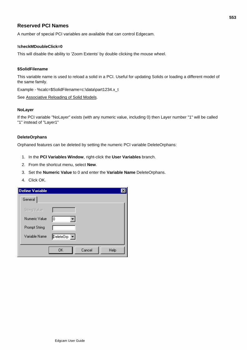
Reserved PCI Names
A number of special PCI variables are available that can control Edgecam.
!checkMDoubleClick=0
This will disable the ability to 'Zoom Extents' by double clicking the mouse wheel.
$SolidFilename
This variable name is used to reload a solid in a PCI. Useful for updating Solids or loading a different model ofthe same family.
Example - %calc=$SolidFilename=c:\data\part1234.x_t
See Associative Reloading of Solid Models.
NoLayer
If the PCI variable "NoLayer" exists (with any numeric value, including 0) then Layer number "1" will be called"1" instead of "Layer1"
DeleteOrphans
Orphaned features can be deleted by setting the numeric PCI variable DeleteOrphans:
In the PCI Variables Window, right-click the User Variables branch.1.
From the shortcut menu, select New.2.
Set the Numeric Value to 0 and enter the Variable Name DeleteOrphans.3.
Click OK.4.
553
Edgcam User Guide
Entity Type Database Numbers
This section lists the Edgecam entities and their corresponding database numbers that are referenced by thePCI.
1 Line
2 Arc
4 Point
5 Conic curve section
6 Helix
7 Bézier curve
8 Spline curve
9 B-Spline curve
10 Continuous
11 Group
12 Symbol
13 Surface Group
14 Generic collection entity (composite)
15 Generic collection entity (shared)
21 Construction line
22 Construction arc
24 Construction point
30 Arrow
31 Witness line
32 Text
33 Font
34 Linear dimension
35 Angular dimension
36 Diametral dimension
37 Radial dimension
38 Hatch area
50 Ruled Surface
51 Surface of revolution
52 Tabulated cylinder surface
53 Coons patch Surface
54 Spline Surface
55 B-Spline Surface
56 Bézier Surface
57 Flowed Surface
61 Joined Surface
65 Surface Curve
66 Toolpath poly
67 Mesh
68 Digital surface
100 Matrix
150 Associativity
151 Property
152 Sweep
153 List
155 Unwrap
156 Wrap
157 Wire (Linked)
158 Wire (Tapered)
159 Wire (Transformed)
160 Solid info
161 Solid body
162 Solid face*
163 Solid loop*
164 Solid edge*
165 Solid vertex*
171 STL entity
201 Toolpath
202 Mod
204 Gd_info
205 Gd_group
206 CPL
207 Layout
213 Pocket, boss or profile with contoured walls feature
214 Pocket, boss or profile with 3D walls feature
215 Set of faces feature
216 Pocket, boss or profile with vertical walls feature
217 Formed, Radial, 3+2,etc, grouped or single hole asFeature
554
Edgcam User Guide

58 Offset Surface
59 Fillet Surface
60 Trimmed Surface
218 Edge Loop feature
219 Open Pocket Feature
250 Stock feature
251 Fixture feature
* You can digitise these to pick the topological object out of the solid entity and pass it to the command, but noEdgecam database entities are created. This means that any entity reference in the PCI will be lost if youreload the part or the solid.
555
Edgcam User Guide

Limitations to PCI
Since PCI is a method of directly manipulating the Edgecam database, it is not applicable outside of the mainEdgecam Design and Manufacture modes. Although both the Code Generator and Tool Library applicationscan be called from within a PCI, neither can interpret PCI directives.
Machining instructions cannot be manipulated directly under the control of PCI. Instruction editing commandscan be called up but require user intervention to select machining instructions.
556
Edgcam User Guide
PCI Example - involute.pci
This example creates an involute form with parameters supplied by the user.
Note that this and other example PCI files can be found in your edge\cam\examples\pci directory.
*
* Demonstration PCI
*
* Create an Involute curve with an option to smooth the resultant lines.
*
* This PCI demonstrates:
*
* %SETPACKAGE
* %ASKBOX
* %CALCSIN() COS()
* %IF %ENDIF
* %GOTO %LABEL
* %DISPLAY
* %ADDFREEDIG
* %OPTION
* Using a loop to create data.
* Holding onto a data array
***********************************
*
%setpackage=0
**** Set default values ****
%calc=diam=10
%calc=ang=0
%calc=eang=360
%calc=deg=30
%label=ask
%ASKBOX=Diameter=diam=Endangle=eang=Degreeincrement=deg
%if[eang]=<0
%display=End angle must be positive.\
%goto=ask
557
Edgcam User Guide
%endif
%if[eang]<=[deg]
%display=End angle is less than increment.\
%goto=ask
%endif
%if[deg]=<0
%display=Degree increment must be greater than 0.\
%goto=ask
%endif
%CALC=RAD=[diam]/2
* Initialising command:- Arc
%INITCOMMAND=cmdh=2,2
%CLEARMODS=[cmdh]
* Setting modifier 'Diameter'
%SETMODIFIER=[cmdh],111,[diam]
* Setting modifier 'Colour'
%SETMODIFIER=[cmdh],1,Green|1
* Setting modifier 'Layer'
%SETMODIFIER=[cmdh],3,88
* Setting modifier 'Style'
%SETMODIFIER=[cmdh],2,Solid|0
%INITDIGINFO=gdh1
* Add Free dig to Digitised input data
%ADDFREEDIG=[gdh1],X0Y0
* Finish Digitised input
%ADDFINISHDIG=[gdh1],[#FINISH]
%EXECCOMMAND=cmdret=[cmdh],[gdh1]
%FREEDIGINFO=[gdh1]
* Initialising command:- Line
%INITCOMMAND=cmdh=2,1
%CLEARMODS=[cmdh]
* Setting modifier 'Polyline'
%SETMODIFIER=[cmdh],155,1
558
Edgcam User Guide
* Setting modifier 'Colour'
%SETMODIFIER=[cmdh],1,Cyan|3
* Setting modifier 'Layer'
%SETMODIFIER=[cmdh],3,88
* Setting modifier 'Style'
%SETMODIFIER=[cmdh],2,Solid|0
%INITDIGINFO=gdh1
* Add Free dig to Digitised input data
%ADDFREEDIG=[gdh1],X[RAD]Y0
*
%LABEL=LOOP
%CALC=ANG=[ANG]+[DEG]
%CALC=LEN=(6.2831853*[RAD])/(360/[ANG])
%CALC=HYP=SQR(([LEN]*[LEN])+([RAD]*[RAD]))
%CALC=HYPANG=ATAN([LEN]/[RAD])
%CALC=REANG=[ANG]-[HYPANG]
%CALC=XCOORD=[HYP]*COS([REANG])
%CALC=YCOORD=[HYP]*SIN([REANG])
* Add Free dig to Digitised input data
%display=End [eang] degrees : [ang] degrees Coord= x[xcoord] y[ycoord]
%ADDFREEDIG=[gdh1],X[XCOORD]Y[YCOORD]
%IF[ANG]=>[EANG]%GOTO=endloop
%GOTO=LOOP
%LABEL=endloop
* Finish Digitised input
%ADDFINISHDIG=[gdh1],[#FINISH]
%EXECCOMMAND=cmdret=[cmdh],[gdh1]
***%FREEDIGINFO=[gdh1]
*
* The %FREEDIGINFO line has been removed so that the data handle can be used for the smooth operation.
*%FREEDIGINFO=[gdh1]
*
********** SMOOTH *********
*
%option=Smooth^Yes^no=smooth
559
Edgcam User Guide
%if[smooth]=2
* No smooth required. Ensure data handle is freed before PCI ends
%FREEDIGINFO=[gdh1]
%goto=nosmooth
%endif
%calc=tol=0.01
%askbox=Tolerance=tol
*
* Initialising command:- Smooth
%INITCOMMAND=cmdh=2,56
%CLEARMODS=[cmdh]
* Setting modifier 'Tolerance'
%SETMODIFIER=[cmdh],56,[tol]
* Setting modifier 'Colour'
%SETMODIFIER=[cmdh],1,Red|4
* Setting modifier 'Layer'
%SETMODIFIER=[cmdh],3,1
* Setting modifier 'Style'
%SETMODIFIER=[cmdh],2,Solid|0
* Setting modifier 'Continuous'
%SETMODIFIER=[cmdh],43,1
*%INITDIGINFO=gdh1
* Remove INITDIGINFO so that the data handle does not get cleared
%EXECCOMMAND=cmdret=[cmdh],[gdh1]
%FREEDIGINFO=[gdh1]
%label=nosmooth
* Initialising command:- Zoom Port
%INITCOMMAND=cmdh=4,6
%CLEARMODS=[cmdh]
* Setting modifier 'Extents'
%SETMODIFIER=[cmdh],8,1
%INITDIGINFO=gdh1
%EXECCOMMAND=cmdret=[cmdh],[gdh1]
%FREEDIGINFO=[gdh1]
560
Edgcam User Guide
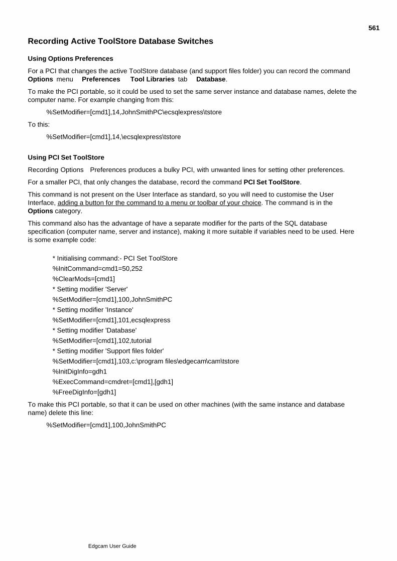
Recording Active ToolStore Database Switches
Using Options Preferences
For a PCI that changes the active ToolStore database (and support files folder) you can record the commandOptions menu Preferences Tool Libraries tab Database.
To make the PCI portable, so it could be used to set the same server instance and database names, delete thecomputer name. For example changing from this:
%SetModifier=[cmd1],14,JohnSmithPC\ecsqlexpress\tstore
To this:
%SetModifier=[cmd1],14,\ecsqlexpress\tstore
Using PCI Set ToolStore
Recording Options Preferences produces a bulky PCI, with unwanted lines for setting other preferences.
For a smaller PCI, that only changes the database, record the command PCI Set ToolStore.
This command is not present on the User Interface as standard, so you will need to customise the UserInterface, adding a button for the command to a menu or toolbar of your choice. The command is in theOptions category.
This command also has the advantage of have a separate modifier for the parts of the SQL databasespecification (computer name, server and instance), making it more suitable if variables need to be used. Hereis some example code:
* Initialising command:- PCI Set ToolStore
%InitCommand=cmd1=50,252
%ClearMods=[cmd1]
* Setting modifier 'Server'
%SetModifier=[cmd1],100,JohnSmithPC
* Setting modifier 'Instance'
%SetModifier=[cmd1],101,ecsqlexpress
* Setting modifier 'Database'
%SetModifier=[cmd1],102,tutorial
* Setting modifier 'Support files folder'
%SetModifier=[cmd1],103,c:\program files\edgecam\cam\tstore
%InitDigInfo=gdh1
%ExecCommand=cmdret=[cmd1],[gdh1]
%FreeDigInfo=[gdh1]
To make this PCI portable, so that it can be used on other machines (with the same instance and databasename) delete this line:
%SetModifier=[cmd1],100,JohnSmithPC
561
Edgcam User Guide

Manufacture Mode
The following chapter helps you learn about and use the basic commands in Edgecam’s Manufacture mode.
To use the Edgecam system, you should be experienced in CAD/CAM methods and the appropriate equipmentand terminology. You also need to have some experience of the Microsoft™ Windows NT™ graphical userenvironments.
562
Edgcam User Guide
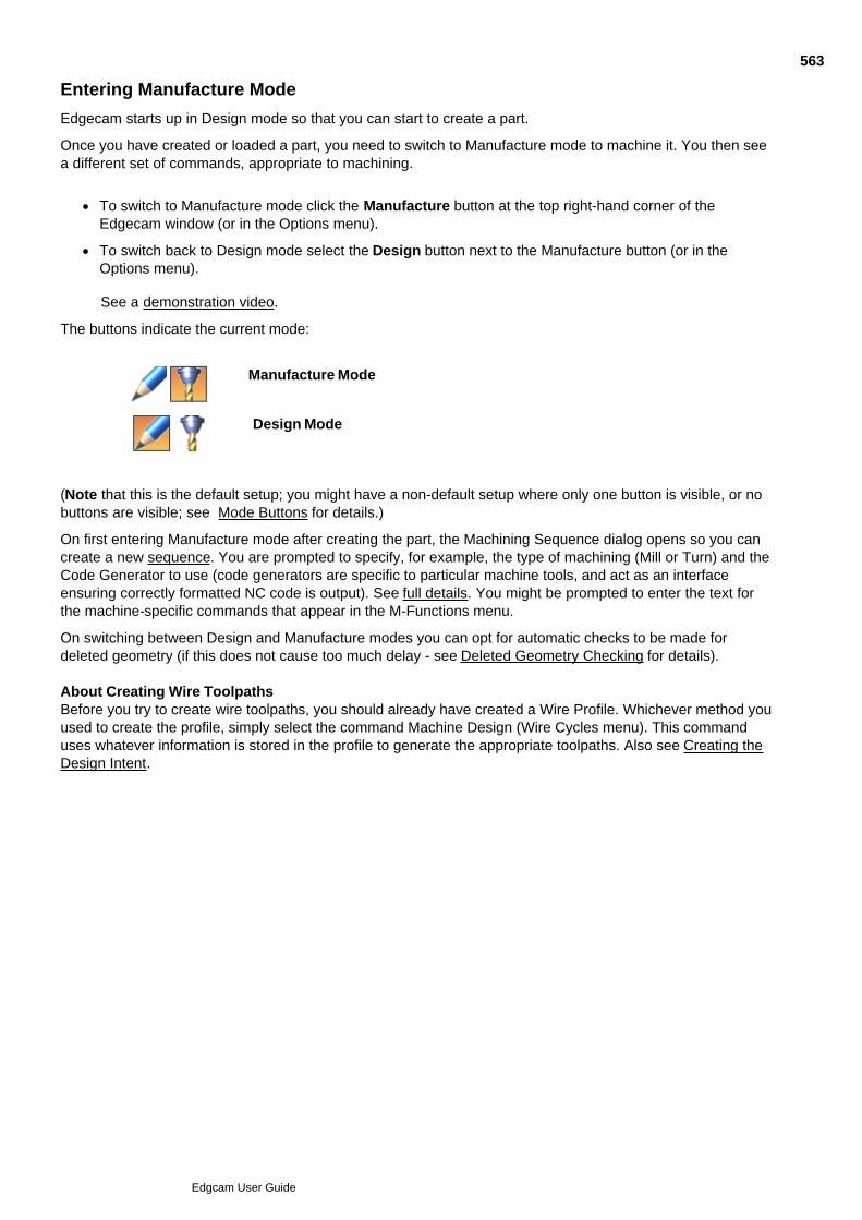
Entering Manufacture Mode
Edgecam starts up in Design mode so that you can start to create a part.
Once you have created or loaded a part, you need to switch to Manufacture mode to machine it. You then seea different set of commands, appropriate to machining.
To switch to Manufacture mode click the Manufacture button at the top right-hand corner of theEdgecam window (or in the Options menu).
To switch back to Design mode select the Design button next to the Manufacture button (or in theOptions menu).
See a demonstration video.
The buttons indicate the current mode:
Manufacture Mode
Design Mode
(Note that this is the default setup; you might have a non-default setup where only one button is visible, or nobuttons are visible; see Mode Buttons for details.)
On first entering Manufacture mode after creating the part, the Machining Sequence dialog opens so you cancreate a new sequence. You are prompted to specify, for example, the type of machining (Mill or Turn) and theCode Generator to use (code generators are specific to particular machine tools, and act as an interfaceensuring correctly formatted NC code is output). See full details. You might be prompted to enter the text forthe machine-specific commands that appear in the M-Functions menu.
On switching between Design and Manufacture modes you can opt for automatic checks to be made fordeleted geometry (if this does not cause too much delay - see Deleted Geometry Checking for details). About Creating Wire ToolpathsBefore you try to create wire toolpaths, you should already have created a Wire Profile. Whichever method youused to create the profile, simply select the command Machine Design (Wire Cycles menu). This commanduses whatever information is stored in the profile to generate the appropriate toolpaths. Also see Creating theDesign Intent.
563
Edgcam User Guide

Setting the Machine Datum Position
When you use File menu New Sequence...
...in the General tab of the Machining Sequence dialog you set the Machine Datum position.
Here are details on this setting in the dialog's help (you can also access this help by clicking the Help button inthe dialog):
564
Edgcam User Guide

Setting the Initial CPL
When you use File menu New Sequence...
...in the General tab of the Machining Sequence dialog you set the Initial CPL.
Here are the details on this setting in the dialog's help (you can also access this help by clicking the Helpbutton in the dialog):
565
Edgcam User Guide
About Machining Sequences
A machining sequence is a set of machining information for an Edgecam part. Depending on the environment,it specifies the:
machine tool (the Code Generator to be used to provide machining commands and to create CNC codefrom the instruction list)
machine datum for the machine tool
axis system being used
turret configurations
machine tool specific functions available (M-Function category commands)
units to be used in the CNC output
sequential list of machining instructions and/or operations.
If a part has been saved, the default sequence is the sequence in use when the part was saved. This sequenceis used for the part at the start of a new Manufacture session.
A new sequence can be defined at any time in Manufacture using the command New Sequence (File menu)
.
An existing sequence can be selected using the command Select Sequence (File menu) .
Parts can contain multiple sequences, for example two milling operations on the same model. Also, more thanone discipline (mill, inspection, turning, and so on) can be used with the same model.
If you have to physically move the workpiece from one setup to another, you should consider using separatesequences, as the output will be for machine tools used in that setup.
If the part is complex, the redraw time may get quite long, so you may want to break it down. However, youmust then merge the files together with an editor (the Edgecam Editor is recommended).
566
Edgcam User Guide

Defining a Machining Sequence
You see the dialog below on first entering Manufacture mode after starting a new part(see more details)
At any time you can open the dialog using File menu Create Sequence.
(You can also access the help below by clicking the Help button in the dialog.)
You can subsequently edit the sequence setup using the Lathe Setup dialog (edits the sub-spindle setup forlathes) and the Machine Parameters dialog (you can also check the values for the current machiningsequence).
567
Edgcam User Guide

Using Probe Feed
Use the Probe Feed command, in the Probing toolbar, to open the dialog below (you can alsoaccess this help from the Help button in the dialog).
568
Edgcam User Guide

Using Probe Bore/Boss
Use the Probe Bore/Boss command, in the Probing toolbar, to open the dialog below (you canalso access this help from the Help button in the dialog).
569
Edgcam User Guide

Using Probe Web/Pocket
Use the Probe Web/Pocket command, in the Probing toolbar, to open the dialog below (you canalso access this help from the Help button in the dialog).
570
Edgcam User Guide

Using Probe Surface
Use the Probe Surface command, in the Probing toolbar, to open the dialog below (you can alsoaccess this help from the Help button in the dialog).
571
Edgcam User Guide
Selecting an Existing Machining Sequence
To use a machining sequence other than the current one you can:
use the Select Sequence (File menu) command and in the subsequent dialog select the sequence from
the drop down list.
In the Sequence Window click on the sequence.
In the Sequence Window right-click on the sequence and select Select from the shortcut menu.
If you want to use a new sequence, use the New Sequence (File menu) command. See Defining a MachiningSequence.
You can remove a machining sequence in a similar manner using the Delete Sequence command. If youdelete the current sequence, you are prompted to pick an existing sequence. If there are no existing machiningsequences, the New Sequence dialog is displayed, allowing you to define one.
572
Edgcam User Guide
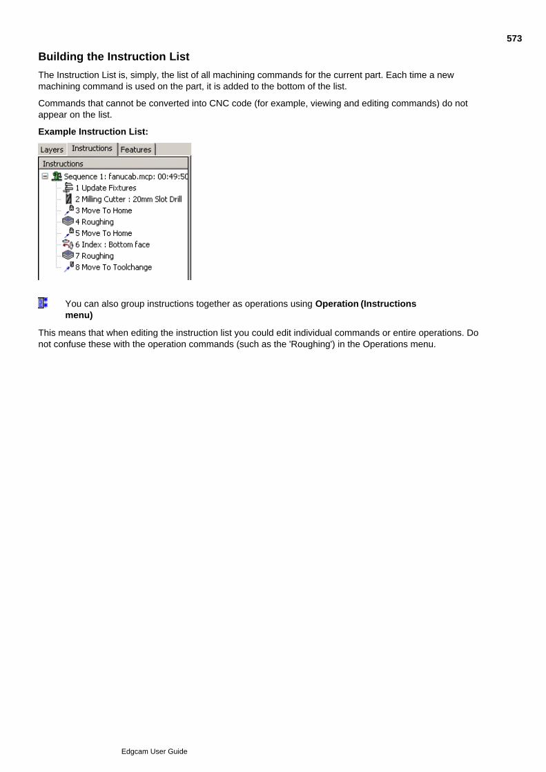
Building the Instruction List
The Instruction List is, simply, the list of all machining commands for the current part. Each time a newmachining command is used on the part, it is added to the bottom of the list.
Commands that cannot be converted into CNC code (for example, viewing and editing commands) do notappear on the list.
Example Instruction List:
You can also group instructions together as operations using Operation (Instructionsmenu)
This means that when editing the instruction list you could edit individual commands or entire operations. Donot confuse these with the operation commands (such as the 'Roughing') in the Operations menu.
573
Edgcam User Guide
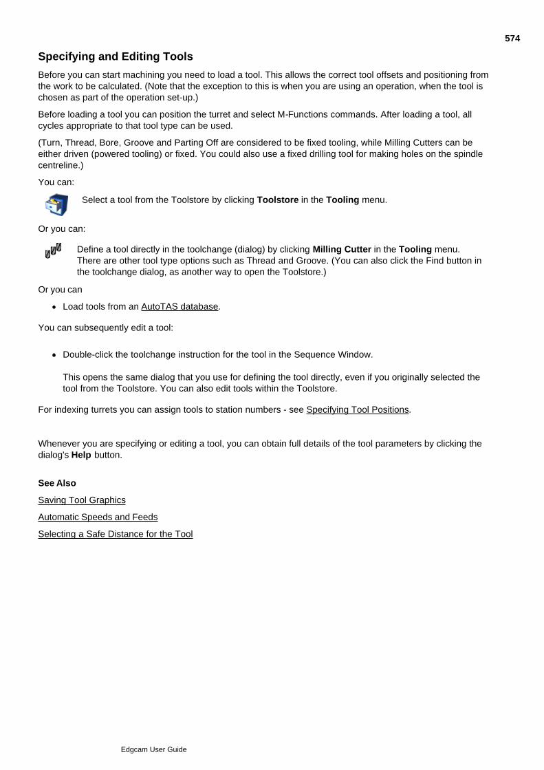
Specifying and Editing Tools
Before you can start machining you need to load a tool. This allows the correct tool offsets and positioning fromthe work to be calculated. (Note that the exception to this is when you are using an operation, when the tool ischosen as part of the operation set-up.)
Before loading a tool you can position the turret and select M-Functions commands. After loading a tool, allcycles appropriate to that tool type can be used.
(Turn, Thread, Bore, Groove and Parting Off are considered to be fixed tooling, while Milling Cutters can beeither driven (powered tooling) or fixed. You could also use a fixed drilling tool for making holes on the spindlecentreline.)
You can:
Select a tool from the Toolstore by clicking Toolstore in the Tooling menu.
Or you can:
Define a tool directly in the toolchange (dialog) by clicking Milling Cutter in the Tooling menu.There are other tool type options such as Thread and Groove. (You can also click the Find button inthe toolchange dialog, as another way to open the Toolstore.)
Or you can
Load tools from an AutoTAS database.
You can subsequently edit a tool:
Double-click the toolchange instruction for the tool in the Sequence Window.
This opens the same dialog that you use for defining the tool directly, even if you originally selected thetool from the Toolstore. You can also edit tools within the Toolstore.
For indexing turrets you can assign tools to station numbers - see Specifying Tool Positions.
Whenever you are specifying or editing a tool, you can obtain full details of the tool parameters by clicking thedialog's Help button.
See Also
Saving Tool Graphics
Automatic Speeds and Feeds
Selecting a Safe Distance for the Tool
574
Edgcam User Guide
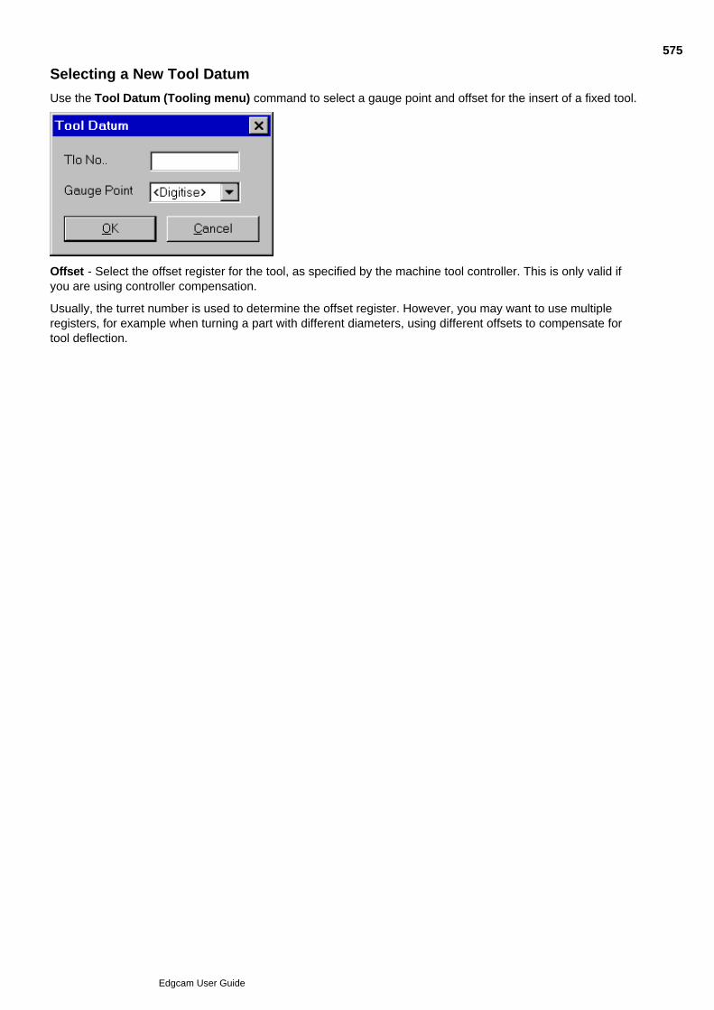
Selecting a New Tool Datum
Use the Tool Datum (Tooling menu) command to select a gauge point and offset for the insert of a fixed tool.
Offset - Select the offset register for the tool, as specified by the machine tool controller. This is only valid ifyou are using controller compensation.
Usually, the turret number is used to determine the offset register. However, you may want to use multipleregisters, for example when turning a part with different diameters, using different offsets to compensate fortool deflection.
575
Edgcam User Guide

Selecting the Wire
Click Select Wire in the Cycles menu to set the parameters for the Wire Machine.
The Select Wire dialog opens, allowing you to specify the wire diameter and guide heights for example.
For full details click the dialog's Help button, or click here.
576
Edgcam User Guide
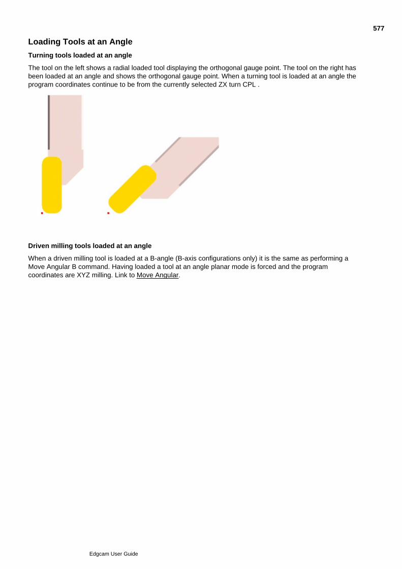
Loading Tools at an Angle
Turning tools loaded at an angle
The tool on the left shows a radial loaded tool displaying the orthogonal gauge point. The tool on the right hasbeen loaded at an angle and shows the orthogonal gauge point. When a turning tool is loaded at an angle theprogram coordinates continue to be from the currently selected ZX turn CPL .
Driven milling tools loaded at an angle
When a driven milling tool is loaded at a B-angle (B-axis configurations only) it is the same as performing aMove Angular B command. Having loaded a tool at an angle planar mode is forced and the programcoordinates are XYZ milling. Link to Move Angular.
577
Edgcam User Guide

Specifying Indexing Turret Tool Positions
When specifying tools for indexing turrets you can assign tools to stations around the turret, using the Positionsetting in the toolchange dialog.
You can set this on initially specifying the tool, or edit it subsequently.
For ToolStore tools, you will need to edit (if necessary), changing the initial value that comes from theToolStore or toolkit. The toolkit value, if specified, overrides the ToolStore value.
You should specify a Position that is 1 or greater, and less than or equal to the number of stations on the turret.
If Position is left blank, it defaults to the last used position (this will probably not be valid, so you should set aposition), or it defaults to 1 for the first toolchange in the sequence.
If Position is higher than the number of stations, the tool is positioned at the highest station number.
Station numbers increase moving clockwise or anti-clockwise around the turret depend on how the turrets'indexing vector' was set up in Code Wizard; the numbering increases anti-clockwise when looking along thevector from its end towards its start point, at 0,0,0. For more details see 'Lower Turret' in the Code WizardHelp.
Specifying a position is especially important for Machine Simulation so that you can check for collisions againstall the tools in the turret.
578
Edgcam User Guide

Using Sandvik Coromant Wiper Inserts
When using a dialog to edit or specify a tool, to use a Sandvik Coromant Wiper insert you make theappropriate Wiper Style setting in the dialog's General tab.
This is in the Turning Tool dialog and the Boring Tool dialog.
Note that:
To maintain surface finish there is a reduction in the feedrate when the tool is not cutting on the wipingportion of the profile. This can happen when cutting tapers for example. See %Feed non Wiper in theillustration above; the default value of %30 (%70 reduction) is recommended. The Finish Turn cycletoolpath is shaded where the wiping portion of the profile is in contact.
Only valid combinations of (insert) Symbol, Nose Radius, Edge Length/Inscribed Circle and Wiper Stylesettings can be made. A table of valid combinations is provided in the online help - see below. (Invalidcombinations result in a 'No Wiper match found' message.)
To machine with a Wiper insert, Radius Compensation (Type) must be set to Pathcomp. The Finish Turncycle will then generate the correct offset for the wiper insert.
For full details click the dialog's Help button (or click here). The details include the valid setting combinations.
579
Edgcam User Guide

Saving Tool Graphics
Saving tool graphics in the ToolStore
The Save Tooling Graphics command in the File menu allows you to save a tool/holder graphic as a.csv file.
The parameters for the command are:
Tool Graphics – Saves current tool graphics data to a .csv file. Click Browse to look for an existing file.
Holder Graphics – Saves current holder graphics data to a .csv file. Click Browse to look for an existing file.
Further information on how to create tool graphics can be found in the ToolStore help. To find therelevant topics:
Open the ToolStore application and click the Help button.1.
Go to the Overview tab.2.
Select the User Defined Graphics link in the See Also list.3.
You cannot create tool graphics with Edgecam in Student Edition mode.
580
Edgcam User Guide
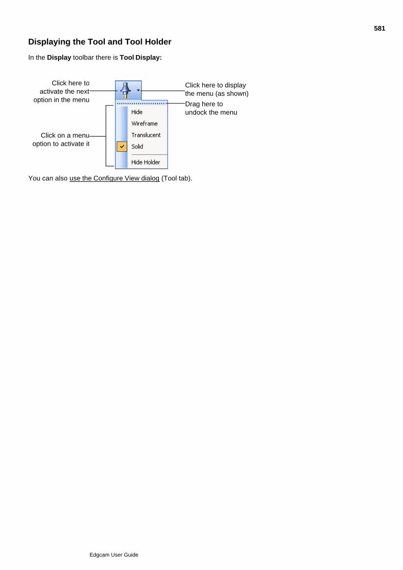
Displaying the Tool and Tool Holder
In the Display toolbar there is Tool Display:
Click here toactivate the next
option in the menu
Click on a menuoption to activate it
Click here to displaythe menu (as shown)
Drag here toundock the menu
You can also use the Configure View dialog (Tool tab).
581
Edgcam User Guide
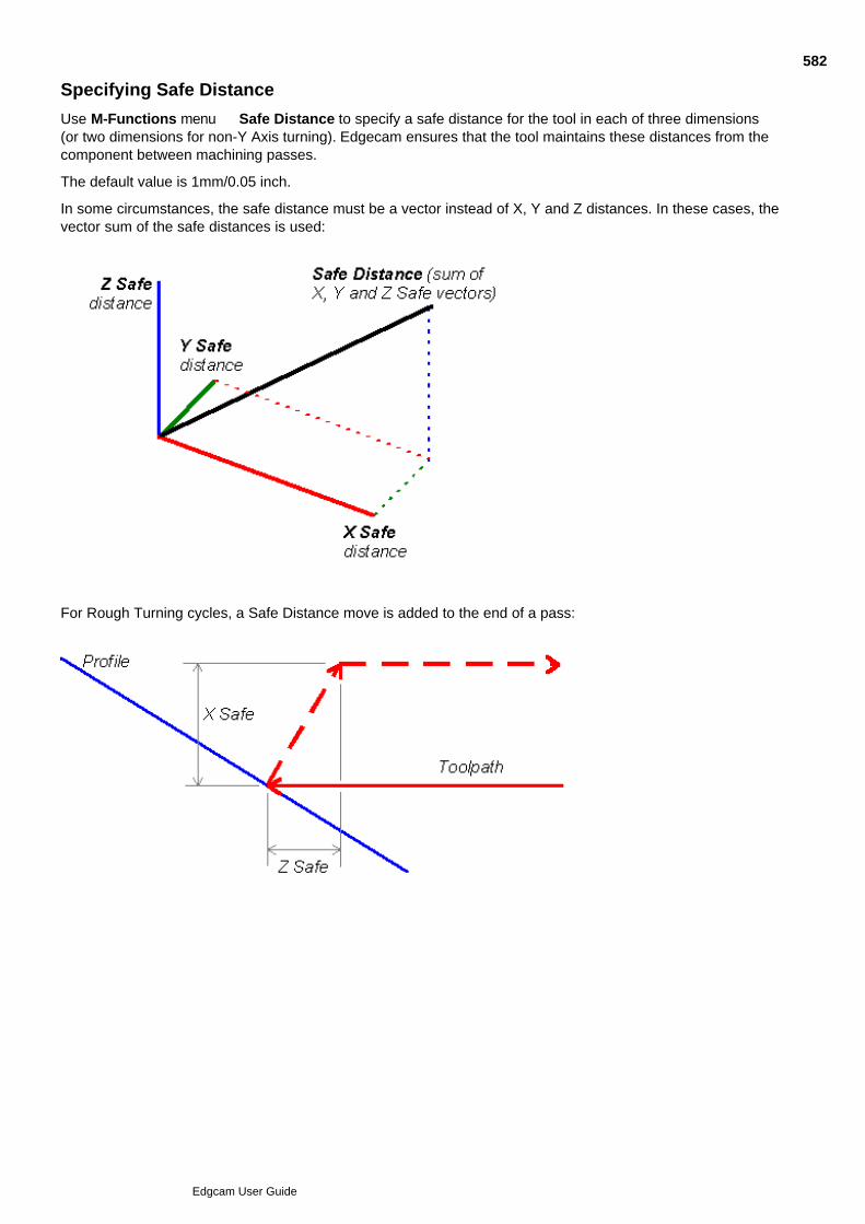
Specifying Safe Distance
Use M-Functions menu Safe Distance to specify a safe distance for the tool in each of three dimensions(or two dimensions for non-Y Axis turning). Edgecam ensures that the tool maintains these distances from thecomponent between machining passes.
The default value is 1mm/0.05 inch.
In some circumstances, the safe distance must be a vector instead of X, Y and Z distances. In these cases, thevector sum of the safe distances is used:
For Rough Turning cycles, a Safe Distance move is added to the end of a pass:
582
Edgcam User Guide

Automatic Speeds and Feeds
In a cycle's dialog, the default Feedrate and Speed entries can be automatically calculated, based on thespecified material and insert.
You can override these with your own values if necessary.
For the automatic values to be calculated:
In Technology Assistant:- Create entries for your material and insert. Then for the combination of materialand insert make sure there specified values for Speed (m/min for example) and Feed (mm/tooth forexample). For more details refer to the Technology Assistant help.
1.
In ToolStore, find the entry for the tool you are to use and start to edit it. In the edit dialog switch to theTechnology tab and for the Insert Link setting, select your created insert.
2.
In Edgecam, use Options menu Model to and select your created material. Select the tool.3.
Now start to create the cycle. In the cycle's dialog you should see automatically calculated Feedrate andSpeed values. The Speed (RPM) value, for example, will have been calculated from the specified insertlinear Speed and the specified tool diameter.
4.
See Also
Selecting values from technology tables in the Tool Library
583
Edgcam User Guide
Using Miscellaneous (M-) Functions
The commands available in the M-Functions menu, and their parameters, depends on the code generator andyour current machining setup (for example in Mill/Turning you need a driven tool selected before Planar Modeand Rotary Mode can be available).
Some of the commands are listed below. For more details click the command dialog's Help button.
Spindle Control
For setting spindle Direction, Gear and so on. Use instead of the Toolchange dialog Spindle control tabsettings if you are not changing tools.
Select Spindle
Switches between Main and Sub spindle.
Synchronise Turrets
Use when using two turrets independently (as opposed to using Four Axis cycles). For later 'adaptive' codegenerators, you also use this to set turret priority (rather than using the Turret Priority command below).
Turret Priority
In twin turret turning, only one turret can be controlling the spindle speed. This is the turret with 'priority'.Priority defaults to the Upper turret. To give priority to another turret you use this command, selecting'Upper' or 'Lower' in the dialog. This only applies to the earlier 'non-adaptive' code generators. For the lateradaptive ones, you use the Reset Priority option in the Synchronise Turrets command (above).
Stop Type
Creates a Program or Optional stop instruction.
Coolant
Provides Mist/Flood/Off or more advanced settings, depending on code generator.
Dwell
Pauses tool movement.
Feed Type
Set to 'Per Minute' or 'Per Rev'.
Input Mode
Use to switch co-ordinate systems for entering positional data, when creating geometry or specifyingmachining cycles.
Tool Local - Specifies the Z axis as equivalent at all times to the tool axis. This allows you to easily specifydistances relative to the tool's current position.
Machine Tool - (Default) Any co-ordinate data input is in terms of the Machine Tool Co-ordinate System.
CSS
Switches to Constant Surface Speed mode.
Update Stock/Fixtures
For updating stock and fixtures.
See Also
Checking the Miscellaneous Functions
584
Edgcam User Guide

Checking the Miscellaneous Functions
You can check the selections that have been made using M-Function menu commandsusing the M_Functions (Verify menu) command.
A message similar to this will be displayed in the feedback window:
The actual items that appear depend upon your current Code Generator file.
Each Code Generator can add extra functions to the M-Functions menu. These functions can be switches (forexample, Coolant On/Off) or values (for example, New Offset). The Code Generator assumes one of theoptions as a default (Coolant is assumed to be on unless otherwise specified). Therefore, if the function has notbeen used, the machine status reports -DEFAULT as shown above.
585
Edgcam User Guide
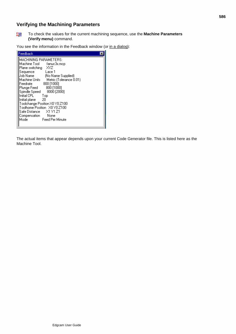
Verifying the Machining Parameters
To check the values for the current machining sequence, use the Machine Parameters(Verify menu) command.
You see the information in the Feedback window (or in a dialog):
The actual items that appear depends upon your current Code Generator file. This is listed here as theMachine Tool.
586
Edgcam User Guide
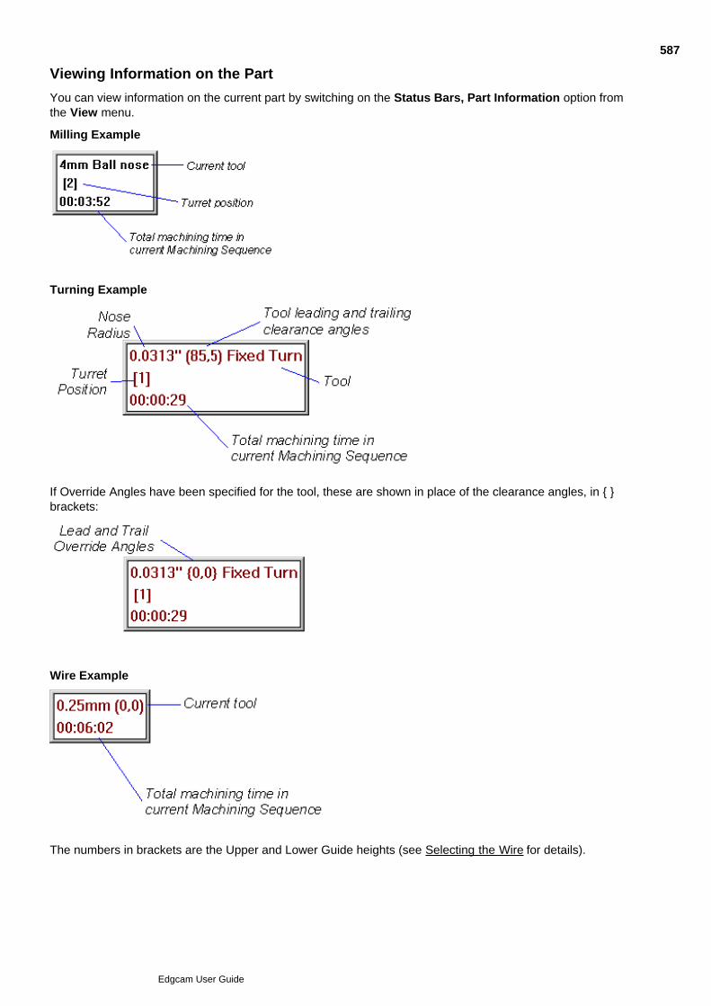
Viewing Information on the Part
You can view information on the current part by switching on the Status Bars, Part Information option fromthe View menu.
Milling Example
Turning Example
If Override Angles have been specified for the tool, these are shown in place of the clearance angles, in { }brackets:
Wire Example
The numbers in brackets are the Upper and Lower Guide heights (see Selecting the Wire for details).
587
Edgcam User Guide

588
Edgcam User Guide

Moving the Tool
The type of tool movement available depends the machining discipline used.
In the Milling environment, the type of movement also depends on whether the 2DSnap button is selected. When selected the tool can only move in the workplane atthe current height. This is the default.
See Also
Moving at the Rapid Rate - Milling and Turning
Moving at the Rapid Rate - Wire
Moving at the Feed Rate
Editing Co-ordinates of Rapid and Feed Moves
Moving the Tool in an Arc at the Feedrate
Moving the Tool around a Co-ordinate Axis
Moving the Tool to the Toolchange Position
Moving the Tool to the Home Position
Moving to the Initial Plane
Freehand Milling
Exact Tool Positioning in Turning
Moving Relative to an Entity
Moving Constrained by Entities
Moving Relative to Two Entities
589
Edgcam User Guide
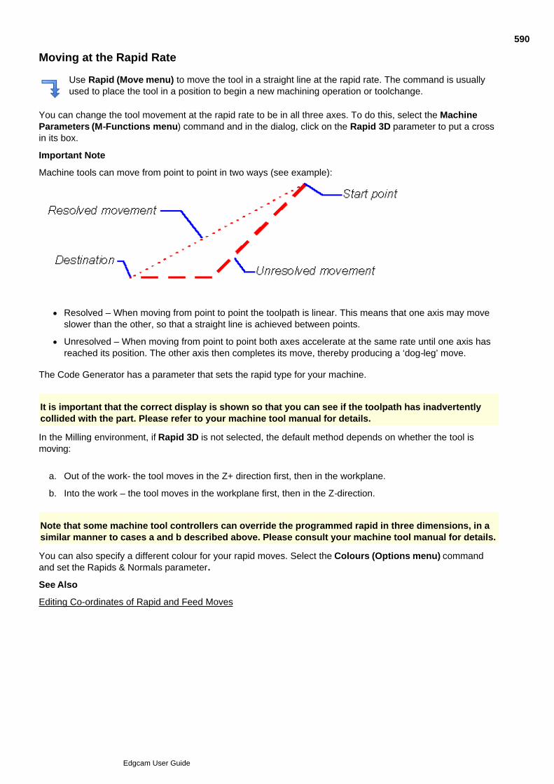
Moving at the Rapid Rate
Use Rapid (Move menu) to move the tool in a straight line at the rapid rate. The command is usuallyused to place the tool in a position to begin a new machining operation or toolchange.
You can change the tool movement at the rapid rate to be in all three axes. To do this, select the MachineParameters (M-Functions menu) command and in the dialog, click on the Rapid 3D parameter to put a crossin its box.
Important Note
Machine tools can move from point to point in two ways (see example):
Resolved – When moving from point to point the toolpath is linear. This means that one axis may moveslower than the other, so that a straight line is achieved between points.
Unresolved – When moving from point to point both axes accelerate at the same rate until one axis hasreached its position. The other axis then completes its move, thereby producing a ‘dog-leg’ move.
The Code Generator has a parameter that sets the rapid type for your machine.
It is important that the correct display is shown so that you can see if the toolpath has inadvertentlycollided with the part. Please refer to your machine tool manual for details.
In the Milling environment, if Rapid 3D is not selected, the default method depends on whether the tool ismoving:
Out of the work- the tool moves in the Z+ direction first, then in the workplane.a.
Into the work – the tool moves in the workplane first, then in the Z-direction.b.
Note that some machine tool controllers can override the programmed rapid in three dimensions, in asimilar manner to cases a and b described above. Please consult your machine tool manual for details.
You can also specify a different colour for your rapid moves. Select the Colours (Options menu) commandand set the Rapids & Normals parameter.
See Also
Editing Co-ordinates of Rapid and Feed Moves
590
Edgcam User Guide

Moving the Wire at the Rapid Rate
Use the Move Rapid (Move menu) command to generate a toolpath for a move in a straight line at the rapidrate.
Warning: Do not use this command while a wire is threaded.
Note that the Code Generator may already be configured to cut the wire and re-thread at the new location.
See Also
Editing Co-ordinates of Rapid and Feed Moves
591
Edgcam User Guide

Moving at the Feed Rate
Use Feed (Move menu) to move the tool or wire to a position at the feedrate. It shouldbe used when the tool may come into contact with the material.
Feed moves can also be used as “freehand” machining commands where more complex machining cycles areunnecessary.
In the milling environment, if 2D Snap is off, the feed move ignores all Z information (for example, from anentity digitise).
See Also
Editing Co-ordinates of Rapid and Feed Moves
592
Edgcam User Guide
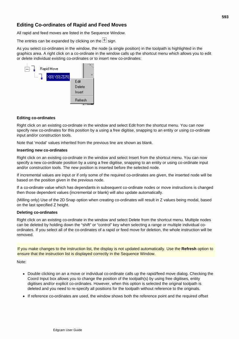
Editing Co-ordinates of Rapid and Feed Moves
All rapid and feed moves are listed in the Sequence Window.
The entries can be expanded by clicking on the sign.
As you select co-ordinates in the window, the node (a single position) in the toolpath is highlighted in thegraphics area. A right click on a co-ordinate in the window calls up the shortcut menu which allows you to editor delete individual existing co-ordinates or to insert new co-ordinates:
Editing co-ordinates
Right click on an existing co-ordinate in the window and select Edit from the shortcut menu. You can nowspecify new co-ordinates for this position by a using a free digitise, snapping to an entity or using co-ordinateinput and/or construction tools.
Note that ‘modal’ values inherited from the previous line are shown as blank.
Inserting new co-ordinates
Right click on an existing co-ordinate in the window and select Insert from the shortcut menu. You can nowspecify a new co-ordinate position by a using a free digitise, snapping to an entity or using co-ordinate inputand/or construction tools. The new position is inserted before the selected node.
If incremental values are input or if only some of the required co-ordinates are given, the inserted node will bebased on the position given in the previous node.
If a co-ordinate value which has dependants in subsequent co-ordinate nodes or move instructions is changedthen those dependent values (incremental or blank) will also update automatically.
(Milling only) Use of the 2D Snap option when creating co-ordinates will result in Z values being modal, basedon the last specified Z height.
Deleting co-ordinates
Right click on an existing co-ordinate in the window and select Delete from the shortcut menu. Multiple nodescan be deleted by holding down the “shift” or “control” key when selecting a range or multiple individual co-ordinates. If you select all of the co-ordinates of a rapid or feed move for deletion, the whole instruction will beremoved.
If you make changes to the instruction list, the display is not updated automatically. Use the Refresh option toensure that the instruction list is displayed correctly in the Sequence Window.
Note:
Double clicking on an a move or individual co-ordinate calls up the rapid/feed move dialog. Checking theCoord Input box allows you to change the position of the toolpath(s) by using free digitises, entitydigitises and/or explicit co-ordinates. However, when this option is selected the original toolpath isdeleted and you need to re-specify all positions for the toolpath without reference to the originals.
If reference co-ordinates are used, the window shows both the reference point and the required offset
593
Edgcam User Guide

from it, e.g. (X 0.000 Y 50.000 Z 0.000) + X10.594
Edgcam User Guide

Moving the Tool in an Arc at the Feedrate
Milling and Turning environment only
Use the Arc (Move menu) command to move the tool in a circular motion in the workplane at the specifiedfeedrate.
Arc moves can also be used as “freehand” machining commands where more complex machining cycles areunnecessary.
2 Point – This parameter controls how the arc move is defined.
If you check the box, you are prompted to digitise a midpoint and an endpoint for the arc move.
If you leave the box unchecked, you are prompted to digitise the endpoint of the arc. The arc leaves thelast move at a tangent and finishes at the endpoint.
595
Edgcam User Guide

Using Move Angular
Use Move menu Angular to open the dialog below (you can also access this help using the Help button in the dialog):
596
Edgcam User Guide

Move to Toolchange
Use Move menu Toolchange to open the dialog below.
(You can also access this help using the dialog's Help button.)
597
Edgcam User Guide

Moving the Tool to the Home Position
Use Home in the Move menu or the Main toolbar to move the tool to its home position.
You use the Move to Home dialog that opens. This includes settings for constraining the move to the X or Yaxes, for example. For details click the dialog's Help button or click here (milling version).
These settings are remembered for when you next open the dialog (the settings are also remembered from theMove to Toolchange dialog; the same settings appear in both dialogs).
The default home position is defined in the Code Generator file, and is specified relative to the Machine Datumand in the orientation of the Initial CPL. To change the Home position, right-click on the sequence name in theSequence Window and in the shortcut menu that opens click Edit. In the Machine Parameters dialog thatopens, switch to the Home tab and make your changes. Note that you cannot change the Home position if thesequence's code generator contains Machine Simulation graphics.
Automatic Moves to Home
You can opt for moves to the Home position to be inserted automatically. The moves are added to the end ofthe sequence on generating CNC code for the sequence (but only if the tool is not already at the Homeposition).
Check Options menu Preferences Toolpaths tab Force Rapid to Home.
The move uses the last settings you made in the Move to Home dialog, when creating a move (or that youmade in the Move to Toolchange dialog).
598
Edgcam User Guide
Moving to the Initial Plane
Milling environment only
Use the Initial Plane (Move menu) command to move the tool to the Initial Plane.
The Initial Plane is a height at which the tool is safe to move without any risk of colliding with any part of theworkpiece, clamps or fixtures. The default value is taken from the Code Generator file.
You can set the height of the Initial Plane by specifying a value for the Initial Plane parameter in the MachineParameters (M-Functions menu command.
Note that while toolchange and home positions are defined in world co-ordinates the initial plane is definedfrom the initial CPL of the sequence. These two datum points may be different.
599
Edgcam User Guide
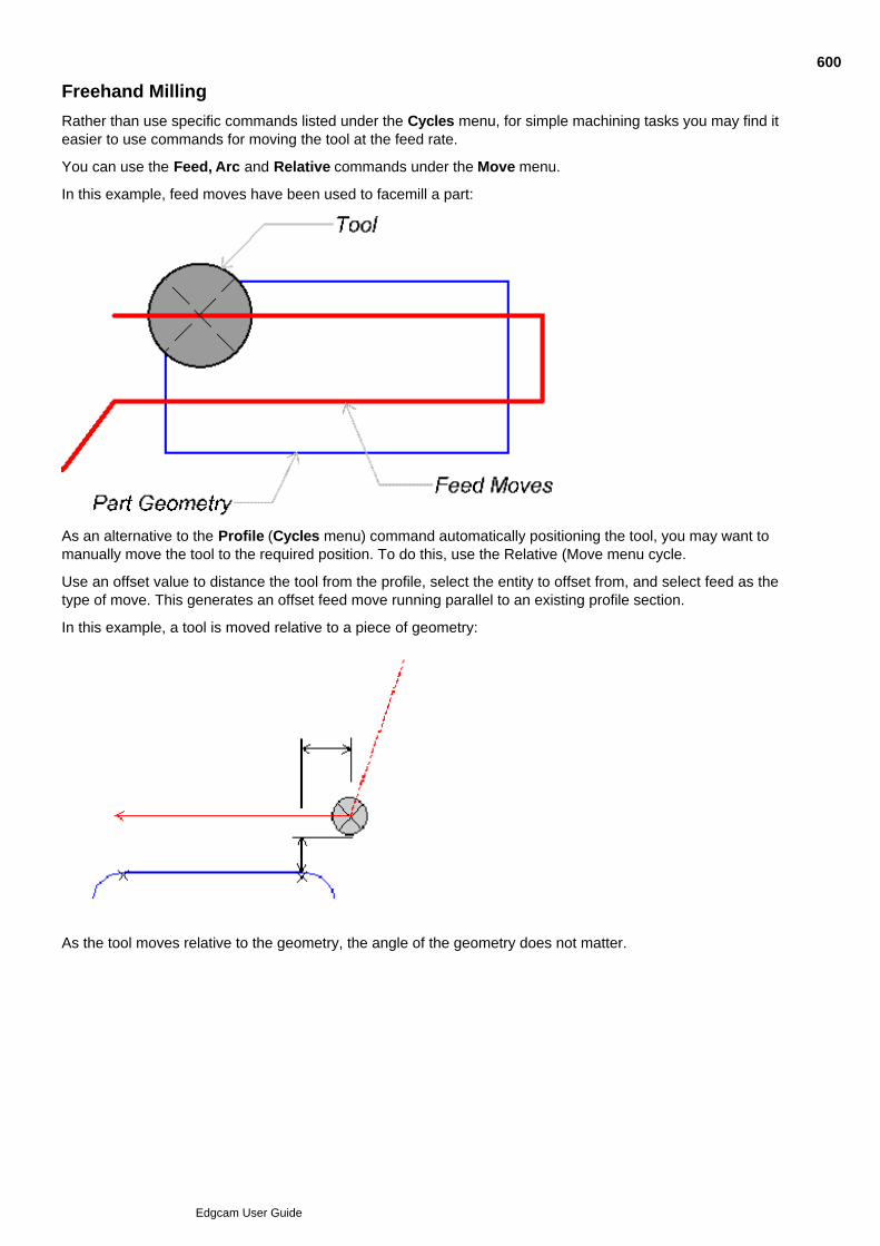
Freehand Milling
Rather than use specific commands listed under the Cycles menu, for simple machining tasks you may find iteasier to use commands for moving the tool at the feed rate.
You can use the Feed, Arc and Relative commands under the Move menu.
In this example, feed moves have been used to facemill a part:
As an alternative to the Profile (Cycles menu) command automatically positioning the tool, you may want tomanually move the tool to the required position. To do this, use the Relative (Move menu cycle.
Use an offset value to distance the tool from the profile, select the entity to offset from, and select feed as thetype of move. This generates an offset feed move running parallel to an existing profile section.
In this example, a tool is moved relative to a piece of geometry:
As the tool moves relative to the geometry, the angle of the geometry does not matter.
600
Edgcam User Guide
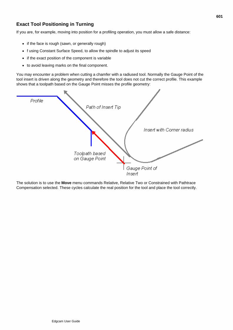
Exact Tool Positioning in Turning
If you are, for example, moving into position for a profiling operation, you must allow a safe distance:
if the face is rough (sawn, or generally rough)
f using Constant Surface Speed, to allow the spindle to adjust its speed
if the exact position of the component is variable
to avoid leaving marks on the final component.
You may encounter a problem when cutting a chamfer with a radiused tool. Normally the Gauge Point of thetool insert is driven along the geometry and therefore the tool does not cut the correct profile. This exampleshows that a toolpath based on the Gauge Point misses the profile geometry:
The solution is to use the Move menu commands Relative, Relative Two or Constrained with PathtraceCompensation selected. These cycles calculate the real position for the tool and place the tool correctly.
601
Edgcam User Guide
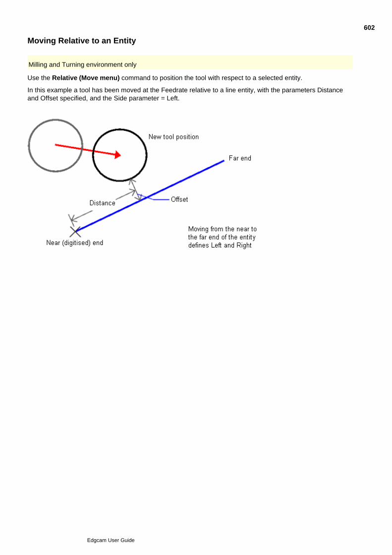
Moving Relative to an Entity
Milling and Turning environment only
Use the Relative (Move menu) command to position the tool with respect to a selected entity.
In this example a tool has been moved at the Feedrate relative to a line entity, with the parameters Distanceand Offset specified, and the Side parameter = Left.
602
Edgcam User Guide
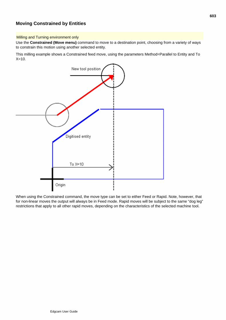
Moving Constrained by Entities
Milling and Turning environment only
Use the Constrained (Move menu) command to move to a destination point, choosing from a variety of waysto constrain this motion using another selected entity.
This milling example shows a Constrained feed move, using the parameters Method=Parallel to Entity and ToX=10.
When using the Constrained command, the move type can be set to either Feed or Rapid. Note, however, thatfor non-linear moves the output will always be in Feed mode. Rapid moves will be subject to the same “dog leg”restrictions that apply to all other rapid moves, depending on the characteristics of the selected machine tool.
603
Edgcam User Guide

Moving Relative to Two Entities
Milling and Turning environment only
Use the Relative Two (Move menu) command to move the tool relative to two other selected entities. The Firstand Second tabs display the movement parameters relative to the first and second entities respectively.
Otherwise, Relative Two uses the same parameters as the other move commands, but with an importantexception – the side of an entity nearest to the tool is defined by which side you digitised the entity.
604
Edgcam User Guide

Moving the Tool in Strategies
Use the Move Dialog command to open the dialog below.
(You can also access this help using the cycle dialog's Help button.)
Note that this command is not present in the User Interface as standard, so you will need to add thecommand button to a toolbar or menu yourself. The command is in the Move category.
605
Edgcam User Guide

Selecting a Cycle
Once you have selected a tool and possibly used a rapid move to bring the tool closer to the work, you areready to select a machining cycle.
You can find all machining cycles permitted by the Code Generator file selected for the machining sequence,and the current tool, in the Cycles menu.
Individual buttons provide another method of selecting the appropriate cycle (which of these are displayed onthe toolbar is also determined by the machining sequence and the current tool).
606
Edgcam User Guide

Finishing a Command
The help refers to the action ‘Perform a Finish’ when describing how to use certain commands. In Edgecam,selecting the right hand mouse button will finish a command.
Alternatively, selecting the Enter/Return key will also finish the command.
You can also use the Finish command.
In the standard configurations this command is not present in the User Interface, so you will need to add thecommand button to a toolbar or menu yourself. The command is in the Input Options category.
607
Edgcam User Guide
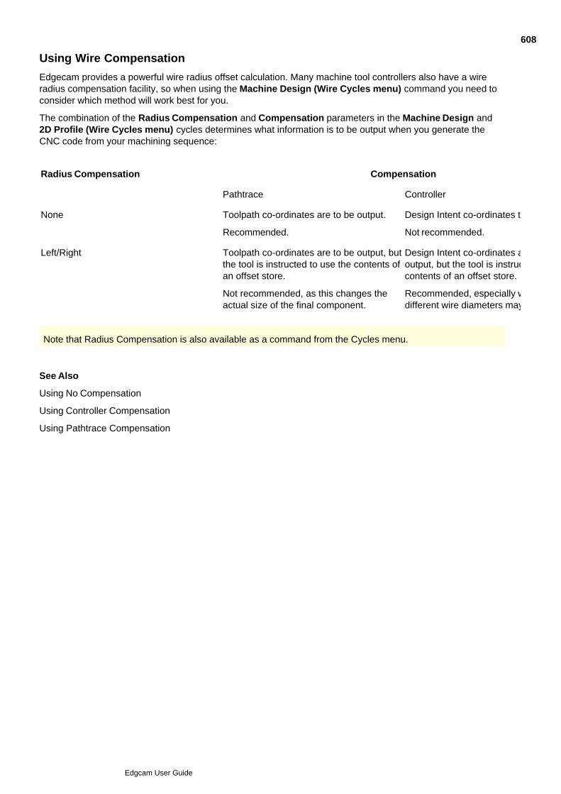
Using Wire Compensation
Edgecam provides a powerful wire radius offset calculation. Many machine tool controllers also have a wireradius compensation facility, so when using the Machine Design (Wire Cycles menu) command you need toconsider which method will work best for you.
The combination of the Radius Compensation and Compensation parameters in the Machine Design and2D Profile (Wire Cycles menu) cycles determines what information is to be output when you generate theCNC code from your machining sequence:
Radius Compensation Compensation
Pathtrace Controller
None Toolpath co-ordinates are to be output.
Recommended.
Design Intent co-ordinates to be output.
Not recommended.
Left/Right Toolpath co-ordinates are to be output, butthe tool is instructed to use the contents ofan offset store.
Not recommended, as this changes theactual size of the final component.
Design Intent co-ordinates are to beoutput, but the tool is instructed to use thecontents of an offset store.
Recommended, especially where manydifferent wire diameters may be used.
Note that Radius Compensation is also available as a command from the Cycles menu.
See Also
Using No Compensation
Using Controller Compensation
Using Pathtrace Compensation
608
Edgcam User Guide
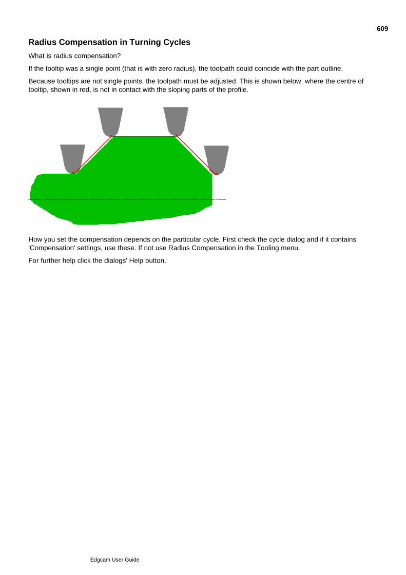
Radius Compensation in Turning Cycles
What is radius compensation?
If the tooltip was a single point (that is with zero radius), the toolpath could coincide with the part outline.
Because tooltips are not single points, the toolpath must be adjusted. This is shown below, where the centre oftooltip, shown in red, is not in contact with the sloping parts of the profile.
How you set the compensation depends on the particular cycle. First check the cycle dialog and if it contains'Compensation' settings, use these. If not use Radius Compensation in the Tooling menu.
For further help click the dialogs' Help button.
609
Edgcam User Guide

Displaying Toolpaths
You can use these methods to control how toolpaths appear on the graphics screen:
The colour for the toolpath is set by its tool. When specifying or editing the tool, set Colour in the Moretab of the tool's dialog. (You can also specify different colours and styles for different parts of the toolpath(rapids for example); in the Options menu click Colours to open the Colour Configuration dialog.)
Use the Mode (View menu) command.
Switch on the Simulation toolbar.
See Also
Controlling the Toolpath Mode
Simulating Tool Movement
610
Edgcam User Guide

Controlling the Toolpath Mode
The Mode (View menu) command controls how tool motion is displayed on the screen.You can restrict the simulation to only cover specific instructions in the instruction listand control the speed of tool/wire motion.
611
Edgcam User Guide
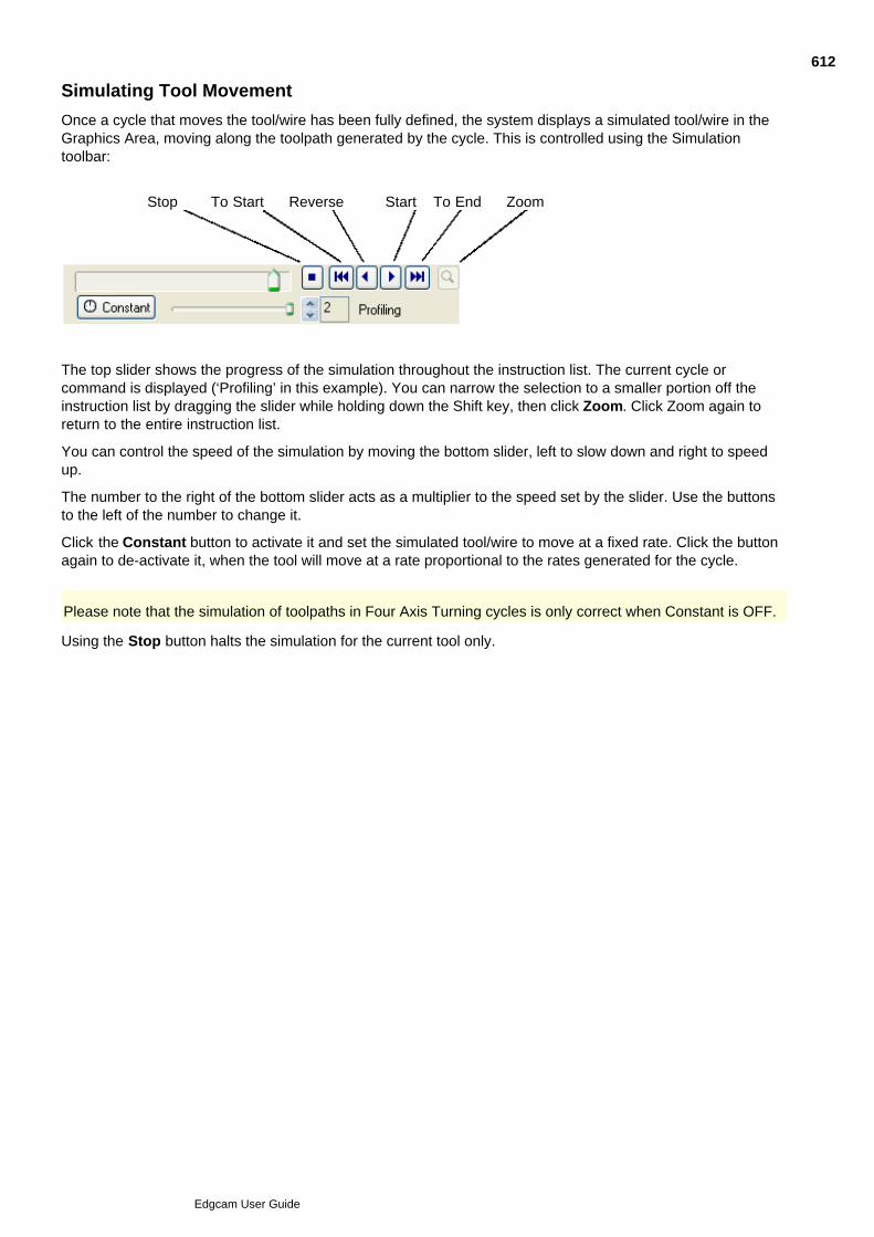
Simulating Tool Movement
Once a cycle that moves the tool/wire has been fully defined, the system displays a simulated tool/wire in theGraphics Area, moving along the toolpath generated by the cycle. This is controlled using the Simulationtoolbar:
Stop To Start Reverse Start To End Zoom
The top slider shows the progress of the simulation throughout the instruction list. The current cycle orcommand is displayed (‘Profiling’ in this example). You can narrow the selection to a smaller portion off theinstruction list by dragging the slider while holding down the Shift key, then click Zoom. Click Zoom again toreturn to the entire instruction list.
You can control the speed of the simulation by moving the bottom slider, left to slow down and right to speedup.
The number to the right of the bottom slider acts as a multiplier to the speed set by the slider. Use the buttonsto the left of the number to change it.
Click the Constant button to activate it and set the simulated tool/wire to move at a fixed rate. Click the buttonagain to de-activate it, when the tool will move at a rate proportional to the rates generated for the cycle.
Please note that the simulation of toolpaths in Four Axis Turning cycles is only correct when Constant is OFF.
Using the Stop button halts the simulation for the current tool only.
612
Edgcam User Guide
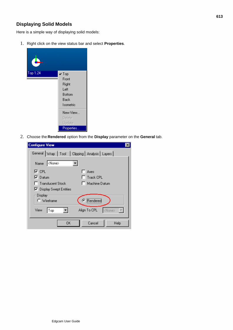
Displaying Solid Models
Here is a simple way of displaying solid models:
Right click on the view status bar and select Properties.1.
Choose the Rendered option from the Display parameter on the General tab.2.
613
Edgcam User Guide

What is Edgecam Milling?
The Milling module provides a two-and-a-half, three and five axis milling capability from the Manufactureenvironment of Edgecam. Various milling (driven) tool types can either be loaded from the ToolStore or definedby parameter. ·
You can drive the tool with respect to the model geometry using these standard types of machining cycle:
Profiling
Pocket Milling
Facemill
Slotting
Hole Production
Surface Milling
The toolpaths resulting from these operations may be then be mirrored, transformed, matrixed or rotated.
If you need to make changes after defining a sequence of these operations you can restructure the sequenceat any time, inserting, editing or removing the individual commands as necessary.
Any changes you make to the original geometry from within the Design environment are reflected in allmachining commands based on that geometry.
Tool movements can be simulated on screen using default or user-generated tool graphics. Full control of thesimulation is provided, including speed controls, swathe mode and simulating specific instructions.
Once a toolpath has been generated, you can display and examine a representation of the material remainingfrom a solid rectangular block. Other methods for examining the results of a toolpath are to render the uncutmesh and reporting on the cycle time.
Most of these features can also be used with the driven tooling of turning centres, enabling C and Y axiscontrol of the tool.
You can also control machine tool specific functions such as coolant on/off.
When satisfied with the machining operations for the part, you can generate CNC code. Edgecam uses CodeGenerator files to interpret the machining sequence into a set of CNC instructions for a specific machine tooltype, and outputs this information to an ASCII text file. You can then use the Edgecam Editor or other editors toexamine and alter this file as required.
614
Edgcam User Guide
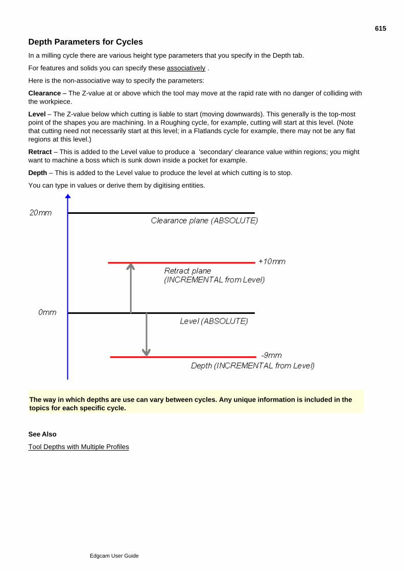
Depth Parameters for Cycles
In a milling cycle there are various height type parameters that you specify in the Depth tab.
For features and solids you can specify these associatively .
Here is the non-associative way to specify the parameters:
Clearance – The Z-value at or above which the tool may move at the rapid rate with no danger of colliding withthe workpiece.
Level – The Z-value below which cutting is liable to start (moving downwards). This generally is the top-mostpoint of the shapes you are machining. In a Roughing cycle, for example, cutting will start at this level. (Notethat cutting need not necessarily start at this level; in a Flatlands cycle for example, there may not be any flatregions at this level.)
Retract – This is added to the Level value to produce a 'secondary' clearance value within regions; you mightwant to machine a boss which is sunk down inside a pocket for example.
Depth – This is added to the Level value to produce the level at which cutting is to stop.
You can type in values or derive them by digitising entities.
The way in which depths are use can vary between cycles. Any unique information is included in thetopics for each specific cycle.
See Also
Tool Depths with Multiple Profiles
615
Edgcam User Guide

Associative Depth Parameters
In solids based machining, you can make cycle's depth parameters associative to the model and its features.
Associative Clearance Illustration
Associative Level Illustration
Associative Depth Illustration
You might set the associative clearance option, in the Roughing cycle:
As the illustrations show, when checked, you specify values that are incremental from key elevations of thesolid or feature to be machined. For example, an associative level will be incremental from the top-most point(highest Z value) of the model you select. When not checked, you specify absolute values. (Note that forfeatures, the 'key elevations' are given by their Level, Depth and Bottom properties.)
Note: These associative parameters are not available when 3D curve profiling.
616
Edgcam User Guide

Tool Depths with Multiple Profiles
If machining multiple profiles, after the first profile is complete the tool will:
Rapid vertically to the clearance plane.1.
Rapid move in the workplane until above the start of the next profile.2.
Rapid down to the retract plane.3.
Feed down to the start point at the depth plane.4.
At the end of the cycle, the tool remains at the depth plane.5.
617
Edgcam User Guide

Using Wireframe Geometry in Cycles - Overview
See:
Specifying pockets
Specifying Pockets with Islands
Specifying Male Parts
Specifying Open Pockets
618
Edgcam User Guide
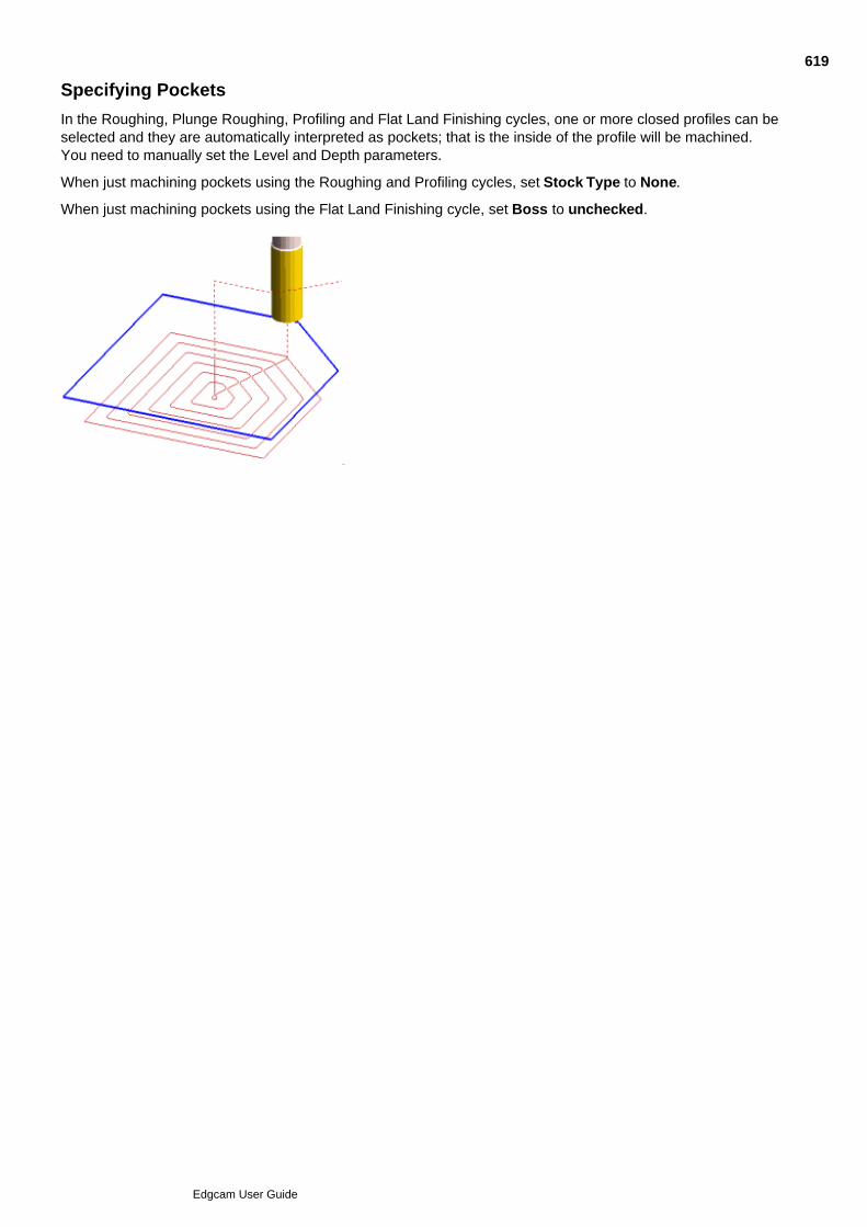
Specifying Pockets
In the Roughing, Plunge Roughing, Profiling and Flat Land Finishing cycles, one or more closed profiles can beselected and they are automatically interpreted as pockets; that is the inside of the profile will be machined.You need to manually set the Level and Depth parameters.
When just machining pockets using the Roughing and Profiling cycles, set Stock Type to None.
When just machining pockets using the Flat Land Finishing cycle, set Boss to unchecked.
619
Edgcam User Guide
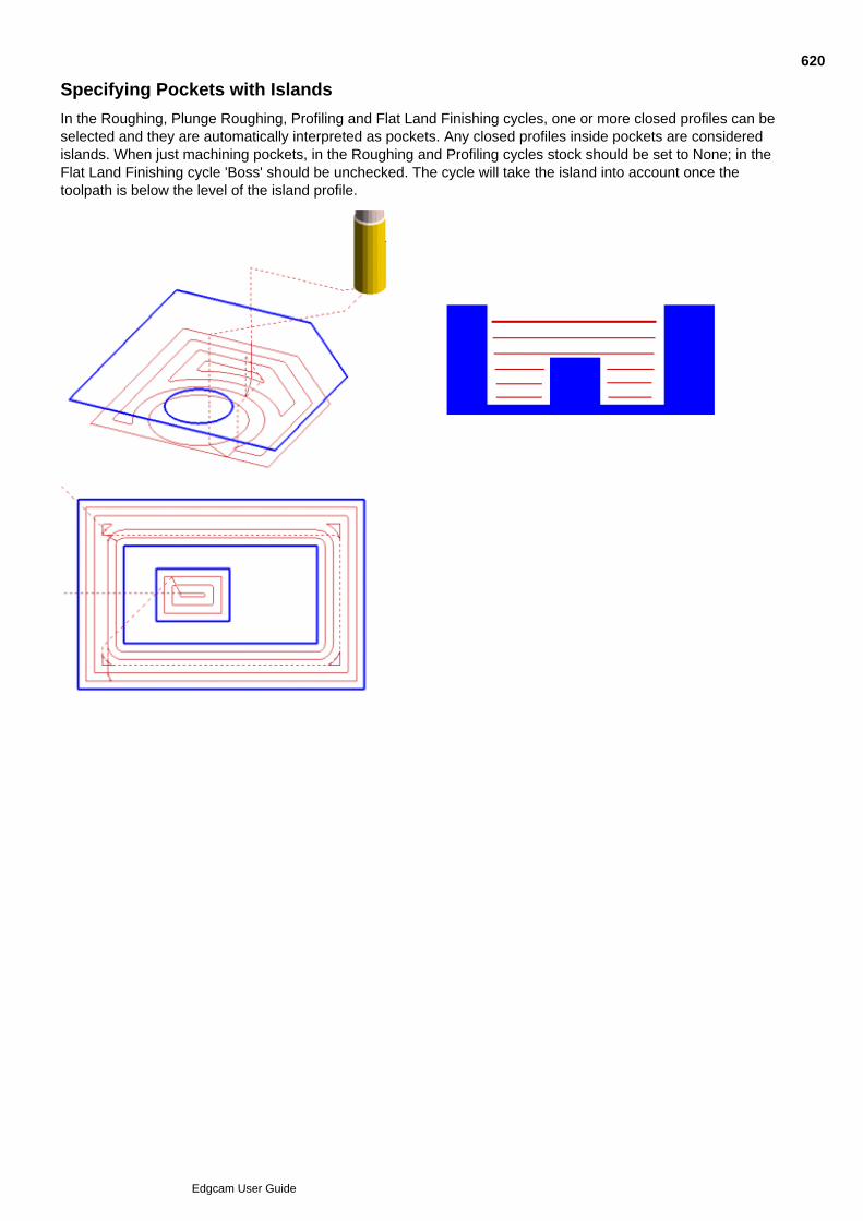
Specifying Pockets with Islands
In the Roughing, Plunge Roughing, Profiling and Flat Land Finishing cycles, one or more closed profiles can beselected and they are automatically interpreted as pockets. Any closed profiles inside pockets are consideredislands. When just machining pockets, in the Roughing and Profiling cycles stock should be set to None; in theFlat Land Finishing cycle 'Boss' should be unchecked. The cycle will take the island into account once thetoolpath is below the level of the island profile.
620
Edgcam User Guide
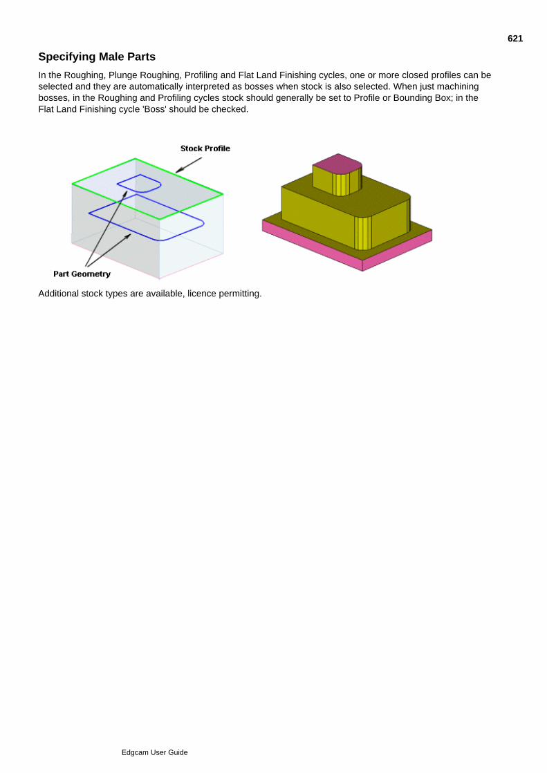
Specifying Male Parts
In the Roughing, Plunge Roughing, Profiling and Flat Land Finishing cycles, one or more closed profiles can beselected and they are automatically interpreted as bosses when stock is also selected. When just machiningbosses, in the Roughing and Profiling cycles stock should generally be set to Profile or Bounding Box; in theFlat Land Finishing cycle 'Boss' should be checked.
Additional stock types are available, licence permitting.
621
Edgcam User Guide
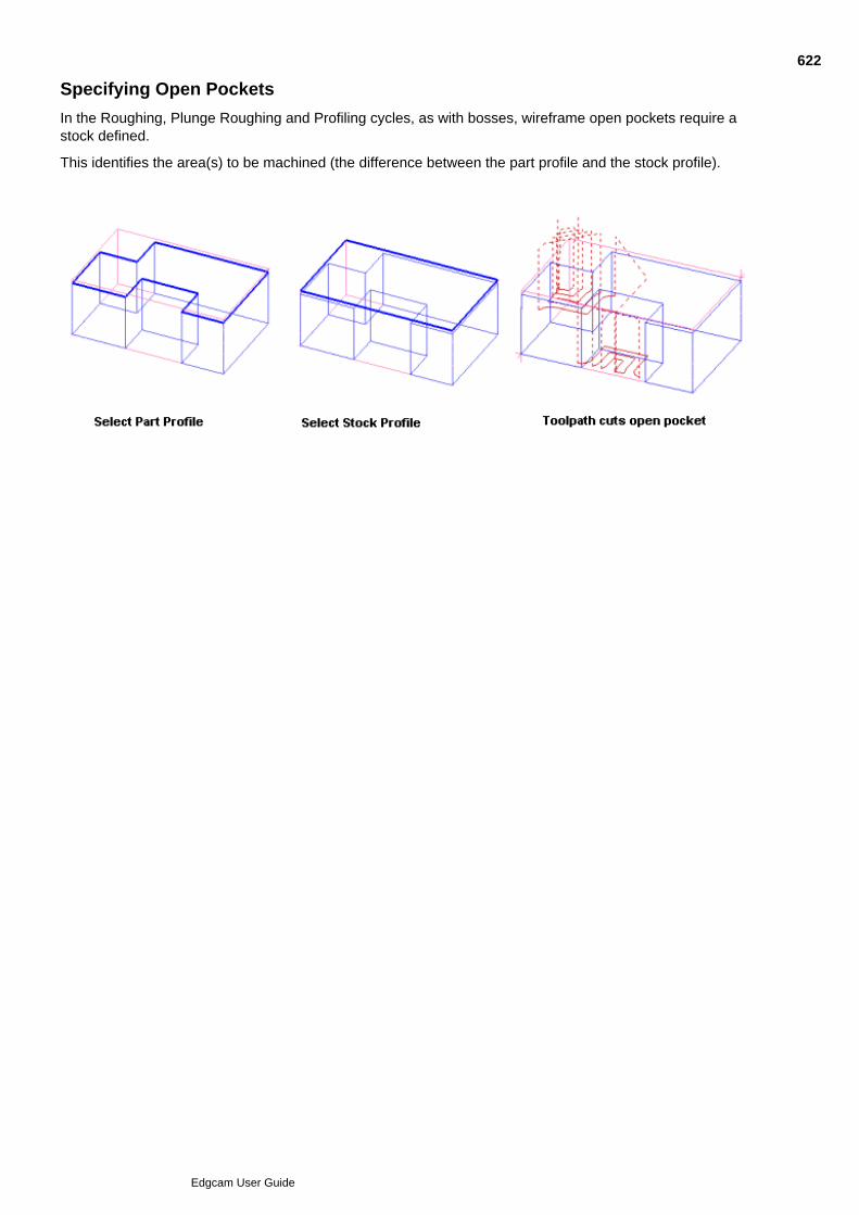
Specifying Open Pockets
In the Roughing, Plunge Roughing and Profiling cycles, as with bosses, wireframe open pockets require astock defined.
This identifies the area(s) to be machined (the difference between the part profile and the stock profile).
622
Edgcam User Guide
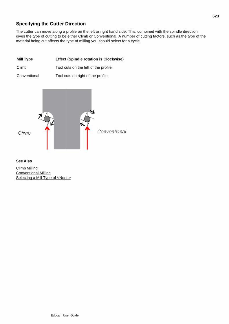
Specifying the Cutter Direction
The cutter can move along a profile on the left or right hand side. This, combined with the spindle direction,gives the type of cutting to be either Climb or Conventional. A number of cutting factors, such as the type of thematerial being cut affects the type of milling you should select for a cycle.
Mill Type Effect (Spindle rotation is Clockwise)
Climb Tool cuts on the left of the profile
Conventional Tool cuts on right of the profile
See Also
Climb MillingConventional MillingSelecting a Mill Type of <None>
623
Edgcam User Guide

Climb Milling
Caution: Using this on a hard material could damage the cutter.
Use Climb milling for soft materials such as aluminium.
The tool moves along the left of the profile, so that the cutter rotates like a wheel rolling along the ground.
Climb is often referred to as ‘Upcut’ when wood routing.
624
Edgcam User Guide

Conventional Milling
Caution: Using this on such a soft material could weld swarf to the surface of the material, resulting ina rough-looking finish.
Use Conventional milling for hard materials such as steel.
As the tool moves along the right of the profile, the cutter rotates so that the cutting forces on the teeth areincreased gradually.
Each tooth starts with a shallow cut that gets thicker until the tooth leaves the material. This action minimisesthe stress on the cutter teeth and the material.
Conventional is often referred to as ‘Downcut’ when wood routing.
625
Edgcam User Guide

Selecting a Mill Type of <None>
Use <None> when the cutter direction is unimportant (as with laser, flame or water cutters), or when cutting softmaterial.
If you select different start points on an open profile, the cycle will stay on the same side but switch to theopposite ends of the profile.
626
Edgcam User Guide

Approaching and Leaving the Work
Most machining cycles automatically move the tool from the current position to approach the start point ofcutting.
In the horizontal plane, the tool moves from its current position to the start point at the rapid rate. The toolmotion then depends on its vertical position. If the tool starts:
Above the Retract plane, the tool rapids to the Retract plane.
Below the Retract plane, the tool rapids up to the Clearance plane and then rapids down to the Retract plane.
The tool then feeds down to the Depth plane, and feeds into position at depth.
For more information, see Using Ramp Moves.
See Also
Selecting a Start Point
Automatically Retracting the Tool
627
Edgcam User Guide

Selecting a Start Point
Once you have selected all entities to be machined by the cycle, most cycles then offer a default start point foreach selected profile.
This default start point and how you can change it varies depending on what type of cycle it is. For moreinformation, read up on that particular type of machining.
628
Edgcam User Guide

Automatically Retracting the Tool
The Finish At parameter allows you to control the behaviour of the tool at the end of that milling cycle. This isnot available in the Hole cycle command.
You may select one of these options:
Depth – The tool remains 'at depth' at the end of the last pass.
Clearance – The tool makes a rapid move to the Clearance plane from 'depth'.
Retract – The tool makes a rapid move to the Retract plane from 'depth'.
629
Edgcam User Guide
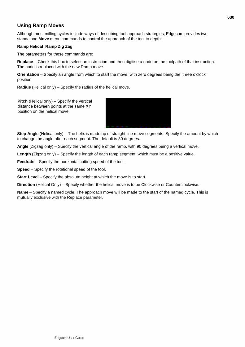
Using Ramp Moves
Although most milling cycles include ways of describing tool approach strategies, Edgecam provides twostandalone Move menu commands to control the approach of the tool to depth:
Ramp Helical Ramp Zig Zag
The parameters for these commands are:
Replace – Check this box to select an instruction and then digitise a node on the toolpath of that instruction.The node is replaced with the new Ramp move.
Orientation – Specify an angle from which to start the move, with zero degrees being the ‘three o’clock’position.
Radius (Helical only) – Specify the radius of the helical move.
Pitch (Helical only) – Specify the verticaldistance between points at the same XYposition on the helical move.
Step Angle (Helical only) – The helix is made up of straight line move segments. Specify the amount by whichto change the angle after each segment. The default is 30 degrees.
Angle (Zigzag only) – Specify the vertical angle of the ramp, with 90 degrees being a vertical move.
Length (Zigzag only) – Specify the length of each ramp segment, which must be a positive value.
Feedrate – Specify the horizontal cutting speed of the tool.
Speed – Specify the rotational speed of the tool.
Start Level – Specify the absolute height at which the move is to start.
Direction (Helical Only) – Specify whether the helical move is to be Clockwise or Counterclockwise.
Name – Specify a named cycle. The approach move will be made to the start of the named cycle. This ismutually exclusive with the Replace parameter.
630
Edgcam User Guide

Defining Stock for the Roughing and Plunge Roughing Cycle
The Roughing and Plunge Roughing cycles offer a number of methods to define the shape of the stock that thepart is to be made from.
By defining a stock type the cycle can determine the most appropriate approach and ensures that all stock isremoved without machining across areas where no stock exists. Stock definition is particularly important foridentifying external areas so the cycle can machine open sided pockets and excess material. When the stock iscoincident with the part the cycle will not generate unnecessary toolpaths
The stock defined in the Roughing cycle is not automatically related to any stock features that may havebeen defined in Design.
The Stock Type command has five options:
For further information on the usage of the different stock types, please click on the links below:
None
3D Model
Thickness
Bounding Box
Profile
The Stock Offset is a 3D offset that can optionally be applied to all stock types, but is required for theThickness type.
Rest Roughing automatically uses to same stock type as the previous roughing cycle.
631
Edgcam User Guide
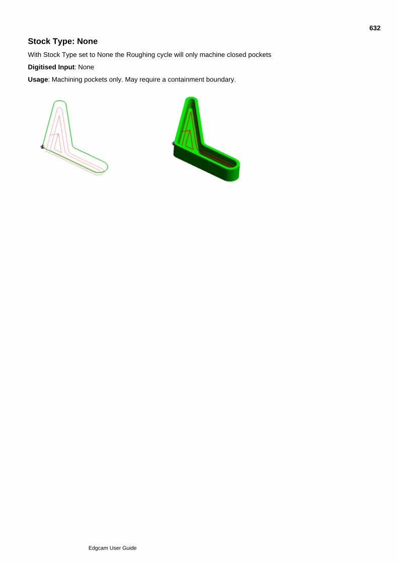
Stock Type: None
With Stock Type set to None the Roughing cycle will only machine closed pockets
Digitised Input: None
Usage: Machining pockets only. May require a containment boundary.
632
Edgcam User Guide
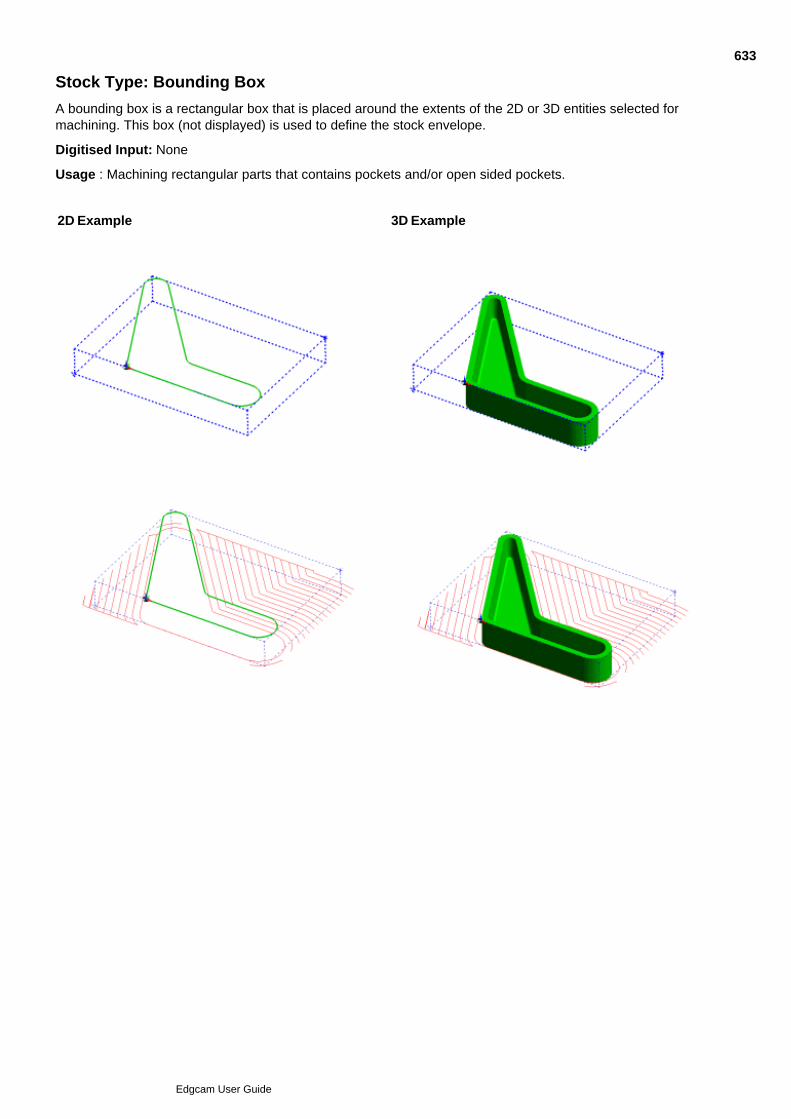
Stock Type: Bounding Box
A bounding box is a rectangular box that is placed around the extents of the 2D or 3D entities selected formachining. This box (not displayed) is used to define the stock envelope.
Digitised Input: None
Usage : Machining rectangular parts that contains pockets and/or open sided pockets.
2D Example 3D Example
633
Edgcam User Guide
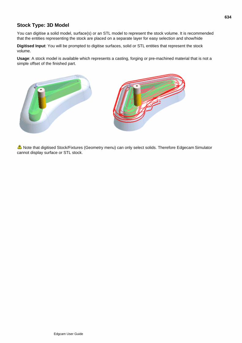
Stock Type: 3D Model
You can digitise a solid model, surface(s) or an STL model to represent the stock volume. It is recommendedthat the entities representing the stock are placed on a separate layer for easy selection and show/hide
Digitised Input: You will be prompted to digitise surfaces, solid or STL entities that represent the stockvolume.
Usage: A stock model is available which represents a casting, forging or pre-machined material that is not asimple offset of the finished part.
Note that digitised Stock/Fixtures (Geometry menu) can only select solids. Therefore Edgecam Simulatorcannot display surface or STL stock.
634
Edgcam User Guide
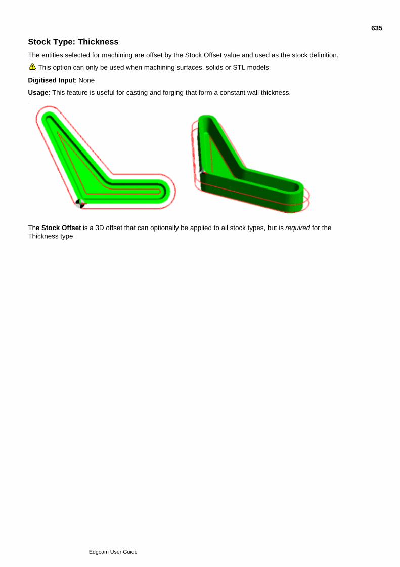
Stock Type: Thickness
The entities selected for machining are offset by the Stock Offset value and used as the stock definition.
This option can only be used when machining surfaces, solids or STL models.
Digitised Input: None
Usage: This feature is useful for casting and forging that form a constant wall thickness.
The Stock Offset is a 3D offset that can optionally be applied to all stock types, but is required for theThickness type.
635
Edgcam User Guide

2D Profile Cycle
Use the Contouring tab of the 2D Profile cycle to make multiple passes around the profile.
(You can also access this help using the cycle dialog's Help button.)
636
Edgcam User Guide
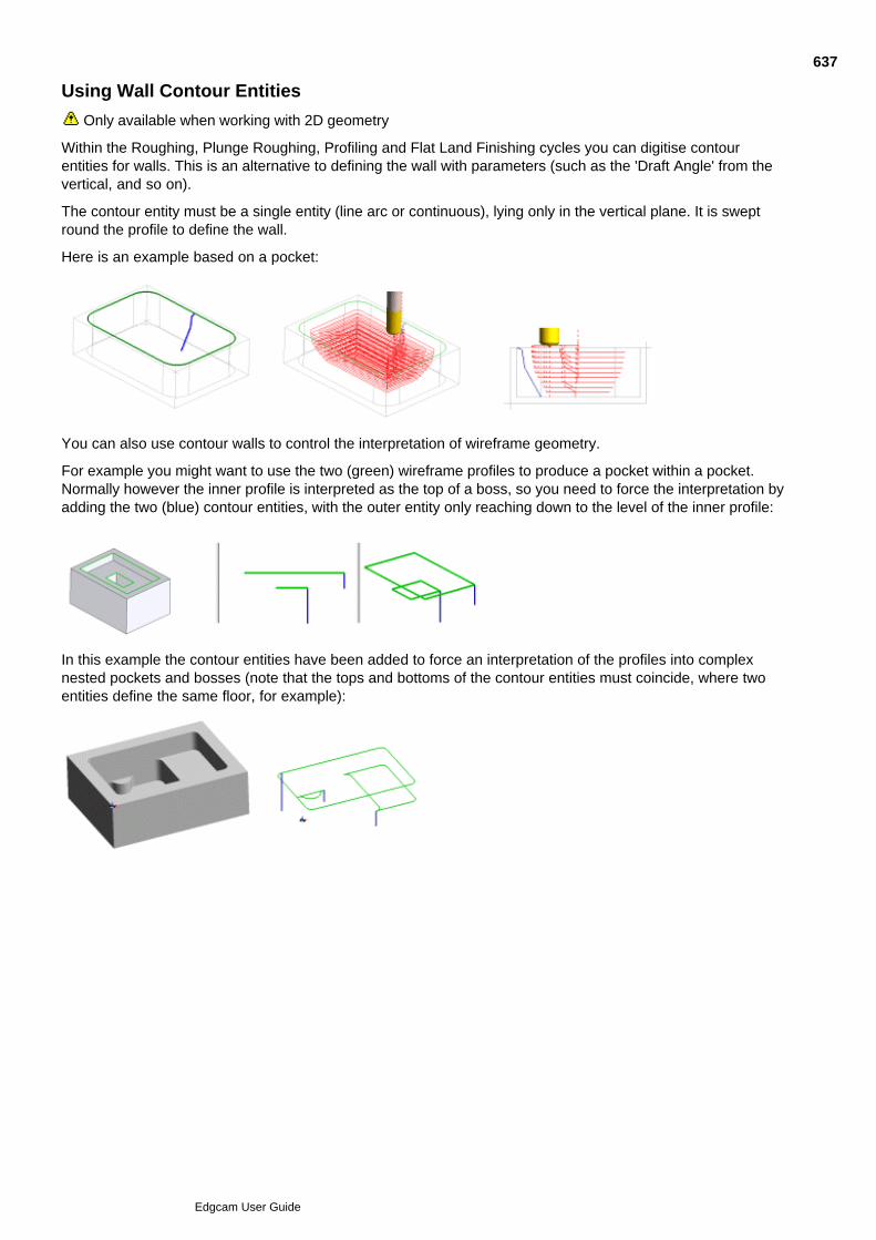
Using Wall Contour Entities
Only available when working with 2D geometry
Within the Roughing, Plunge Roughing, Profiling and Flat Land Finishing cycles you can digitise contourentities for walls. This is an alternative to defining the wall with parameters (such as the 'Draft Angle' from thevertical, and so on).
The contour entity must be a single entity (line arc or continuous), lying only in the vertical plane. It is sweptround the profile to define the wall.
Here is an example based on a pocket:
You can also use contour walls to control the interpretation of wireframe geometry.
For example you might want to use the two (green) wireframe profiles to produce a pocket within a pocket.Normally however the inner profile is interpreted as the top of a boss, so you need to force the interpretation byadding the two (blue) contour entities, with the outer entity only reaching down to the level of the inner profile:
In this example the contour entities have been added to force an interpretation of the profiles into complexnested pockets and bosses (note that the tops and bottoms of the contour entities must coincide, where twoentities define the same floor, for example):
637
Edgcam User Guide
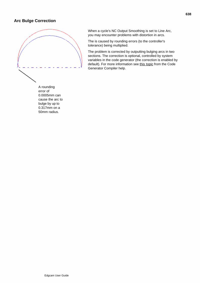
Arc Bulge Correction
A roundingerror of0.0005mm cancause the arc tobulge by up to0.317mm on a50mm radius.
When a cycle's NC Output Smoothing is set to Line Arc,you may encounter problems with distortion in arcs.
The is caused by rounding errors (to the controller'stolerance) being multiplied.
The problem is corrected by outputting bulging arcs in twosections. The correction is optional, controlled by systemvariables in the code generator (the correction is enabled bydefault). For more information see this topic from the CodeGenerator Compiler help.
638
Edgcam User Guide

Radius Rounding Error Correction on almost Complete Arcs
Edgecam prevents errors being caused by arc moves that form almost a complete circle, and use 'R'; as in thisexample CNC code:
G2 X10.432 Y12.475 R50
In this situation the controller has to calculate the arc centre point. In the CNC file the arc Start point, End pointand Radius are rounded to the format limitation of the Controller. This small error is amplified by the arc radiusand can lead to the centre point being out of position by an unacceptable distance.
Exact Start/End Rounded Start/End
The error is monitored, and to prevent it becoming unacceptable a switch to IJK output is enforced.
This solution is only implemented in code generators based on Version 9.75, or later, templates.
639
Edgcam User Guide
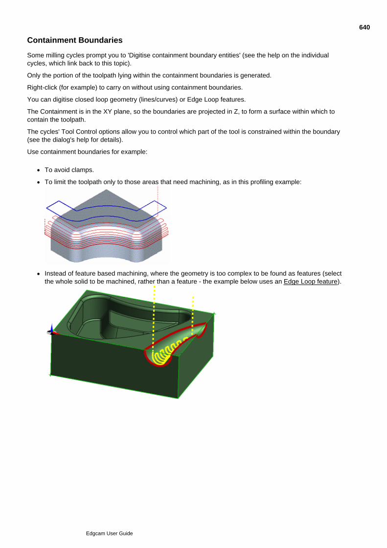
Containment Boundaries
Some milling cycles prompt you to 'Digitise containment boundary entities' (see the help on the individualcycles, which link back to this topic).
Only the portion of the toolpath lying within the containment boundaries is generated.
Right-click (for example) to carry on without using containment boundaries.
You can digitise closed loop geometry (lines/curves) or Edge Loop features.
The Containment is in the XY plane, so the boundaries are projected in Z, to form a surface within which tocontain the toolpath.
The cycles' Tool Control options allow you to control which part of the tool is constrained within the boundary(see the dialog's help for details).
Use containment boundaries for example:
To avoid clamps.
To limit the toolpath only to those areas that need machining, as in this profiling example:
Instead of feature based machining, where the geometry is too complex to be found as features (selectthe whole solid to be machined, rather than a feature - the example below uses an Edge Loop feature).
640
Edgcam User Guide
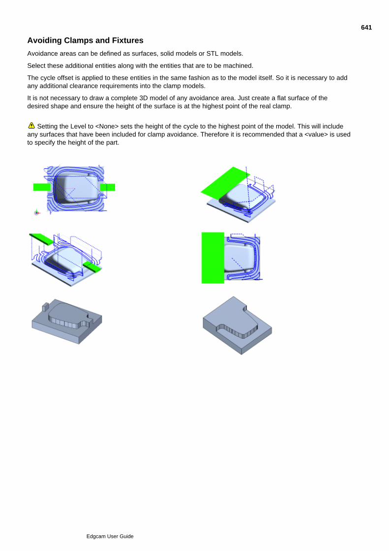
Avoiding Clamps and Fixtures
Avoidance areas can be defined as surfaces, solid models or STL models.
Select these additional entities along with the entities that are to be machined.
The cycle offset is applied to these entities in the same fashion as to the model itself. So it is necessary to addany additional clearance requirements into the clamp models.
It is not necessary to draw a complete 3D model of any avoidance area. Just create a flat surface of thedesired shape and ensure the height of the surface is at the highest point of the real clamp.
Setting the Level to <None> sets the height of the cycle to the highest point of the model. This will include
any surfaces that have been included for clamp avoidance. Therefore it is recommended that a <value> is usedto specify the height of the part.
641
Edgcam User Guide
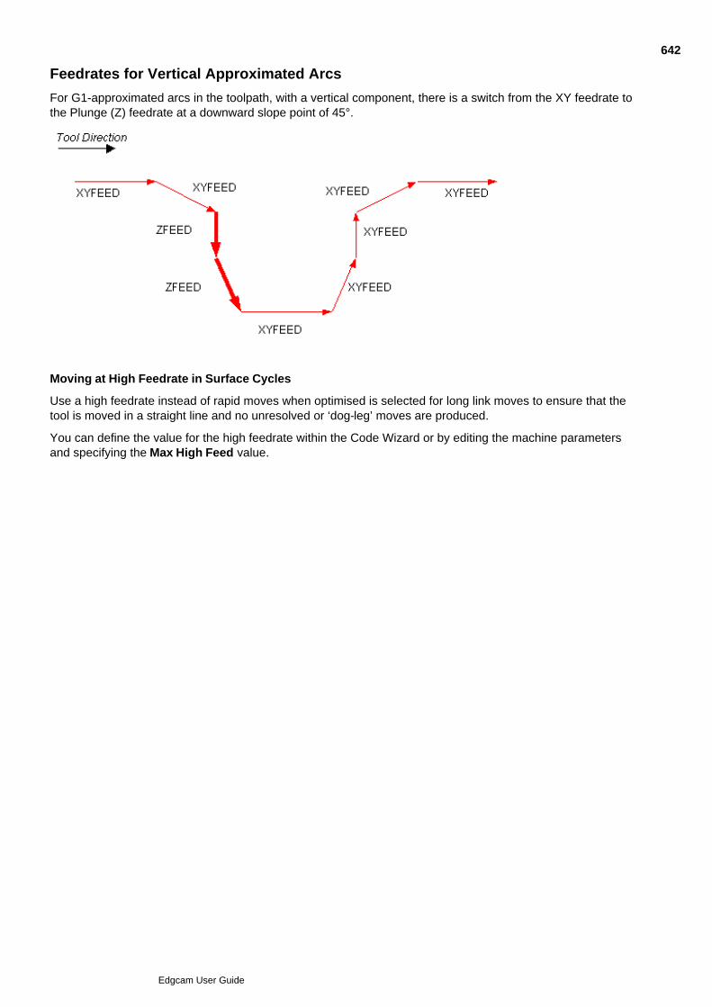
Feedrates for Vertical Approximated Arcs
For G1-approximated arcs in the toolpath, with a vertical component, there is a switch from the XY feedrate tothe Plunge (Z) feedrate at a downward slope point of 45°.
Moving at High Feedrate in Surface Cycles
Use a high feedrate instead of rapid moves when optimised is selected for long link moves to ensure that thetool is moved in a straight line and no unresolved or ‘dog-leg’ moves are produced.
You can define the value for the high feedrate within the Code Wizard or by editing the machine parametersand specifying the Max High Feed value.
642
Edgcam User Guide

Face Milling cycle
Use Mill Cycles menu Face Milling to open the dialog below.
(You can also access this help using the cycle dialog's Help button.)
643
Edgcam User Guide

2D Profile Cycle
Use Mill Cycles menu 2D Profile to open the dialog below.
(You can also access this help using the cycle dialog's Help button.)
644
Edgcam User Guide

Planar Milling
'Planar Milling' refers to cycles which can only operate on flat planes, as opposed to surface or solid basedcycles.
Use these commands for driving the tool on or around a profile:
2D Profile (Mill Cycles menu)
Move menu Relative for precise tool positioning relative to the profile's geometry. Make sure you haveread the methods for chaining and branching.
Use these commands or methods for pocketing and stock removal:
Facemill (Mill Cycles menu)
Freehand machining (Move menu commands).
Use these operations to combine several machining commands (see Operations in Milling for details):
Facemilling (Operations menu)
See Also
Slotting
645
Edgcam User Guide

2D Profile Cycle
Use the Advaced tab of the 2D Profile cycle to make settings such as dynamic billeting andengraving.
(You can also access this help using the cycle dialog's Help button.)
646
Edgcam User Guide
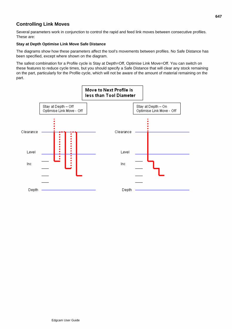
Controlling Link Moves
Several parameters work in conjunction to control the rapid and feed link moves between consecutive profiles.These are:
Stay at Depth Optimise Link Move Safe Distance
The diagrams show how these parameters affect the tool’s movements between profiles. No Safe Distance hasbeen specified, except where shown on the diagram.
The safest combination for a Profile cycle is Stay at Depth=Off, Optimise Link Move=Off. You can switch onthese features to reduce cycle times, but you should specify a Safe Distance that will clear any stock remainingon the part, particularly for the Profile cycle, which will not be aware of the amount of material remaining on thepart.
647
Edgcam User Guide
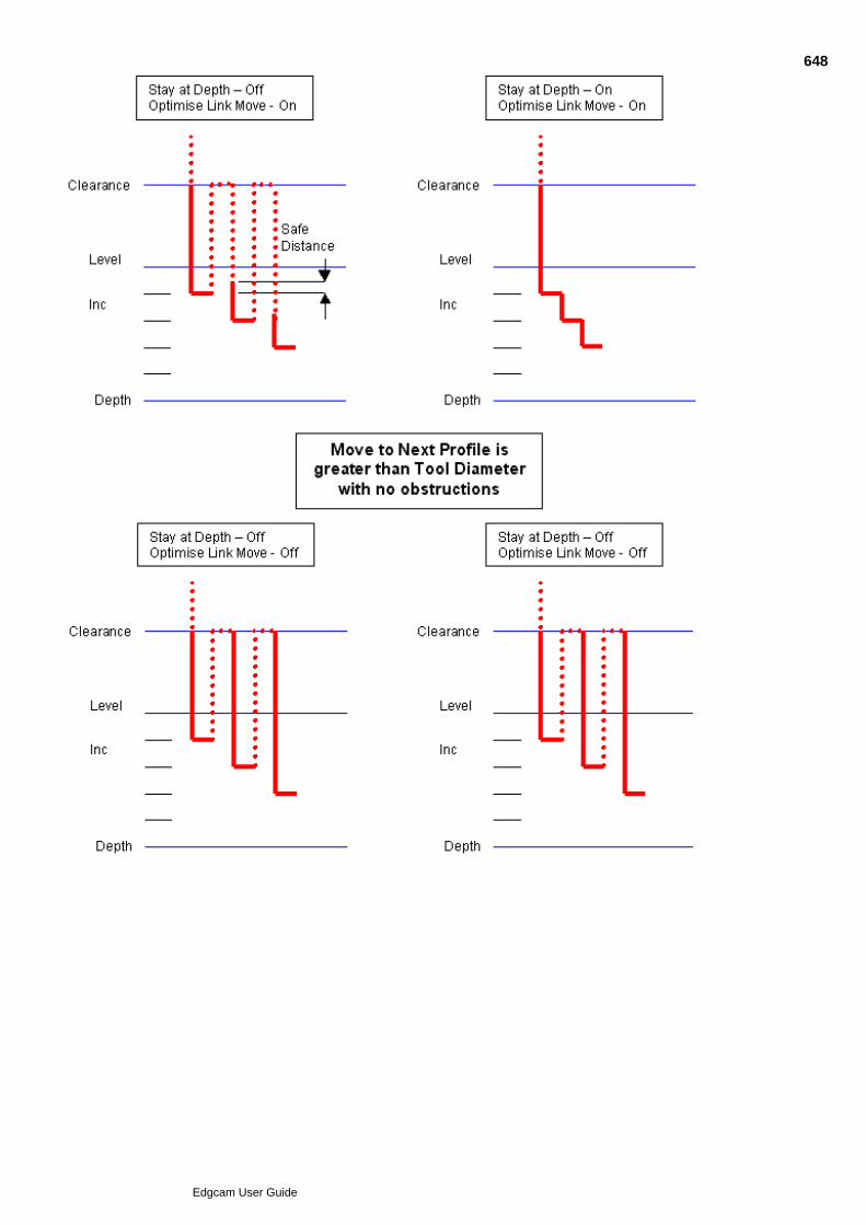
648
Edgcam User Guide
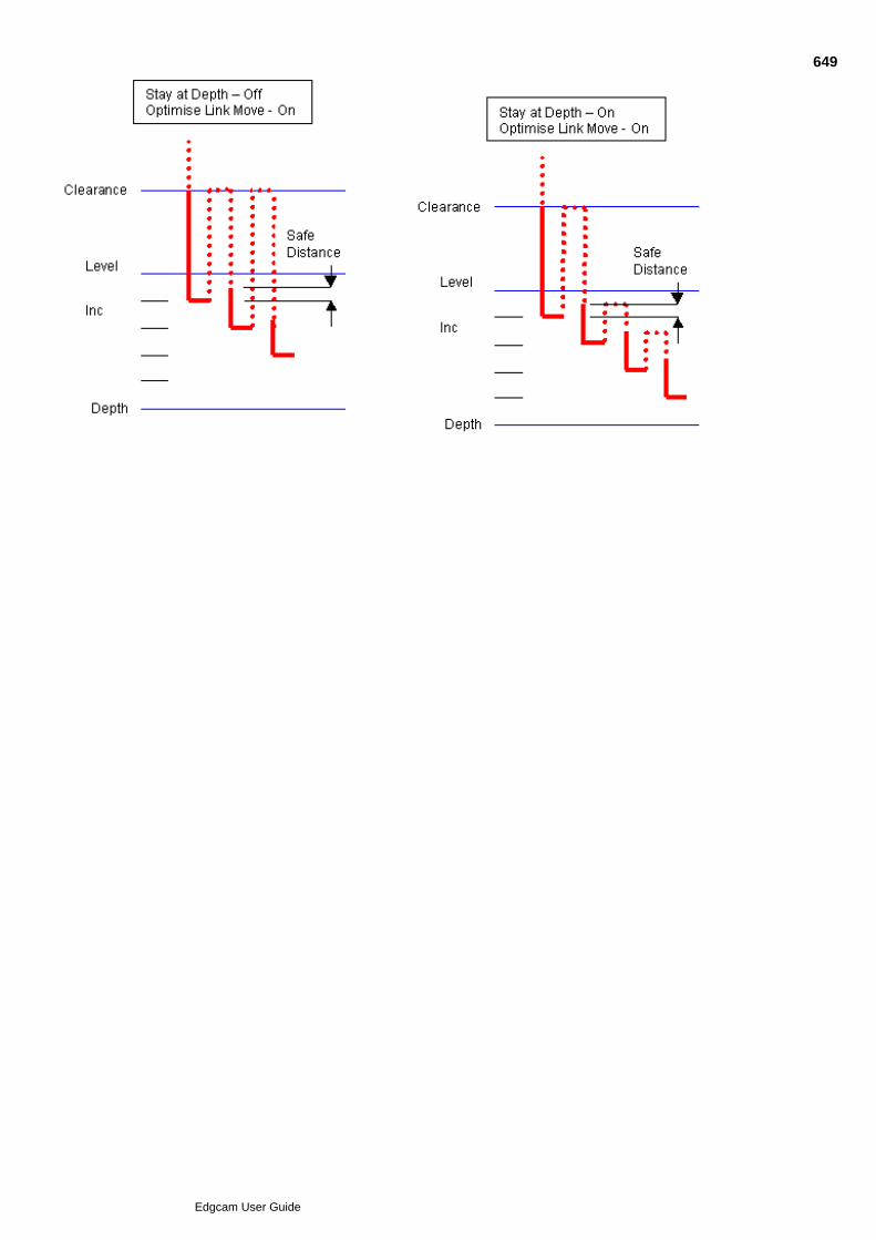
649
Edgcam User Guide

Hole Cycle
Use Mill Cycles menu Hole Cycle to machine holes.
Here are details on using the cycle, and on the cycle's settings (you can also access this help by clicking theHelp button in the dialog):
650
Edgcam User Guide

Hole Cycle General tab
In the General tab of the Hole Cycle you make general settings such as the feedrates and strategy (Drill, Reamand so on).
Here are details on the tab's settings (you can also access this help by clicking the Help button in the dialog):
651
Edgcam User Guide

Hole Cycle Depth tab
In the Depth tab of the Hole Cycle you make the depth settings for the cycle.
Here are details on the tab's settings (you can also access this help by clicking the Help button in the dialog):
652
Edgcam User Guide

Hole Cycle Filtering tab
The Filtering tab is useful tab for filtering out geometry to machine from multiple geometry digitises, forexample.
Here are details on the tab's settings (you can also access this help by clicking the Help button in the dialog):
653
Edgcam User Guide

Thread Milling
Edgecam’s Thread Mill (Mill Cycles menu) command allows you to create a thread upor down the vertical axis of the machine. The cycle supports straight, taper, multi-startand arc lead-in/lead-out options. You can also machine multiple threads within the samecommand.
Note that the thread units can differ from the units used for the rest of the part. If you get an unexpected resultfrom this cycle, check the values you used for the cycle parameters.
This example shows four views of a single-start external thread with an arc lead in and out.
Normally, you start defining the thread by selecting an arc entity. This arc represents the major diameter of anexternal thread, or the minor diameter of an internal thread (see example). You can also digitise a point thatrepresents the centre of the thread (when using the thread milling cycle with hole features for example). In thiscase, use the Major/Minor Diameter fields on the Thread tab to specify the major/minor diameter for thethread.
On the Depth tab, you can use the Level and Depth parameters to define the start and end heights for thethread. Alternatively, depths may be specified as distances above and below the defined geometry using theUpper and Lower Distance parameters. All measurements are taken from the bottom of the thread, so if youdefine an overlapping tool, the system mills a thread above this height.
On the Thread tab, the Thread Side parameter sets the thread as internal or external, and the Hand of Threadparameter sets the thread as left or right-handed. See Defining the Thread.
The thread's direction of cut depends on these parameter values and is explained under Determining theThread Mill Cut Direction.
See Also
Defining the Thread
Making Single Start Threads
Making Multiple Starts
Cutting One Pitch at a Time
Leading In and Out in Thread Milling
How the Thread Mill Cycle Calculates the Feed Rate
Compensating for the Tool Radius in Thread Milling
Specifying Tooling Parameters for Thread Mill
654
Edgcam User Guide
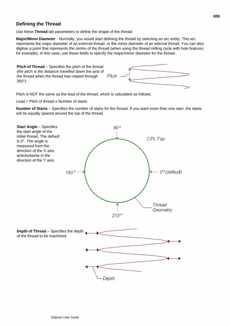
Defining the Thread
Use these Thread tab parameters to define the shape of the thread:
Major/Minor Diameter - Normally, you would start defining the thread by selecting an arc entity. This arcrepresents the major diameter of an external thread, or the minor diameter of an internal thread. You can alsodigitise a point that represents the centre of the thread (when using the thread milling cycle with hole featuresfor example). In this case, use these fields to specify the major/minor diameter for the thread.
Pitch of Thread – Specifies the pitch of the thread(the pitch is the distance travelled down the axis ofthe thread when the thread has rotated through360°).
Pitch is NOT the same as the lead of the thread, which is calculated as follows:
Lead = Pitch of thread x Number of starts.
Number of Starts – Specifies the number of starts for the thread. If you want more than one start, the startswill be equally spaced around the top of the thread.
Start Angle – Specifiesthe start angle of theinitial thread. The defaultis 0°. The angle ismeasured from thedirection of the X axisanticlockwise in thedirection of the Y axis.
Depth of Thread – Specifies the depthof the thread to be machined.
655
Edgcam User Guide

Thread Side – Selects an Internal or External thread.
Hand of Thread – Selects a Right or Left-Handed thread. See Also
Determining the Thread Mill Cut Direction
Cutting a Tapered Thread
656
Edgcam User Guide
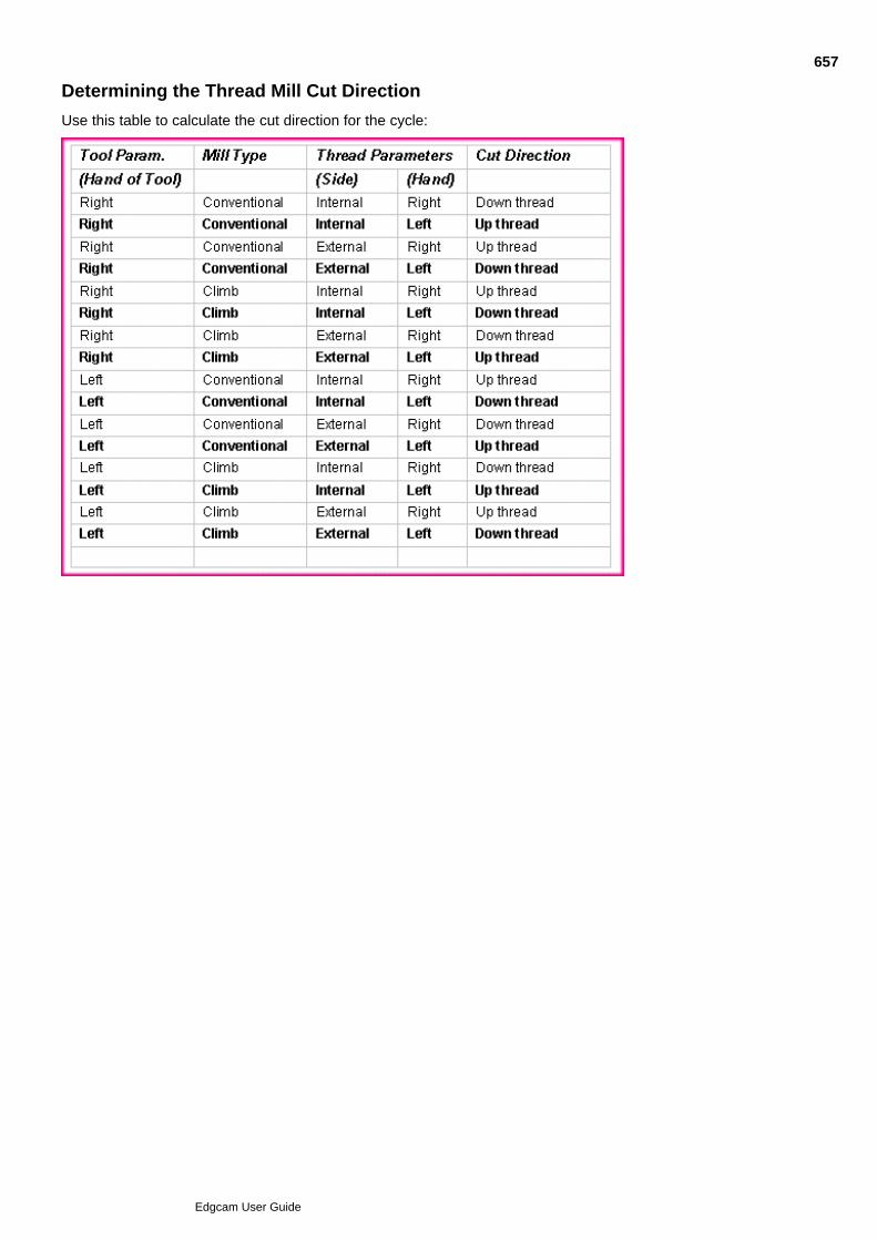
Determining the Thread Mill Cut Direction
Use this table to calculate the cut direction for the cycle:
657
Edgcam User Guide
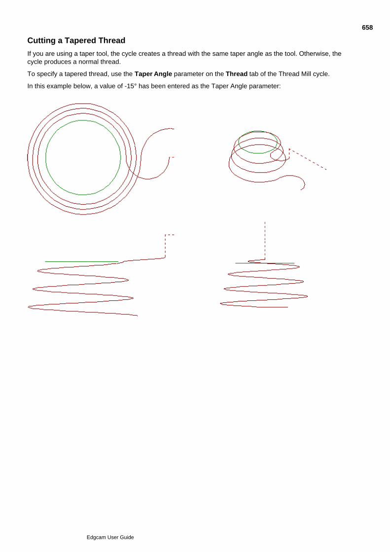
Cutting a Tapered Thread
If you are using a taper tool, the cycle creates a thread with the same taper angle as the tool. Otherwise, thecycle produces a normal thread.
To specify a tapered thread, use the Taper Angle parameter on the Thread tab of the Thread Mill cycle.
In this example below, a value of -15° has been entered as the Taper Angle parameter:
658
Edgcam User Guide
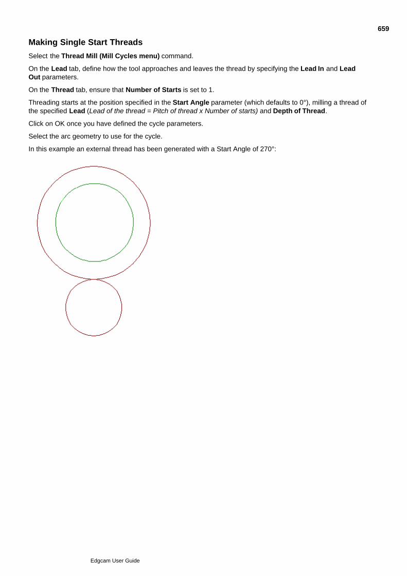
Making Single Start Threads
Select the Thread Mill (Mill Cycles menu) command.
On the Lead tab, define how the tool approaches and leaves the thread by specifying the Lead In and LeadOut parameters.
On the Thread tab, ensure that Number of Starts is set to 1.
Threading starts at the position specified in the Start Angle parameter (which defaults to 0°), milling a thread ofthe specified Lead (Lead of the thread = Pitch of thread x Number of starts) and Depth of Thread.
Click on OK once you have defined the cycle parameters.
Select the arc geometry to use for the cycle.
In this example an external thread has been generated with a Start Angle of 270°:
659
Edgcam User Guide

Making Multiple Starts
To Mill a Thread with Multiple Starts
Select the Thread Mill (Mill Cycles menu) command. A box appears containing the parameters for thecycle.
1.
Define how the tool approaches and leaves the thread by specifying the Lead parameters.2.
On the Thread tab, specify the Number of Starts required.3.
Use the Change Start Height parameter to specify how the other starts approach the thread (only validfor threading downwards). See Changing the Start Height when Making Multiple Starts.
4.
Click on OK after you have defined the cycle parameters.5.
Digitise the arc geometry to use for the cycle.6.
Perform a Finish.7.
The toolpaths are now generated for the cycle.
660
Edgcam User Guide
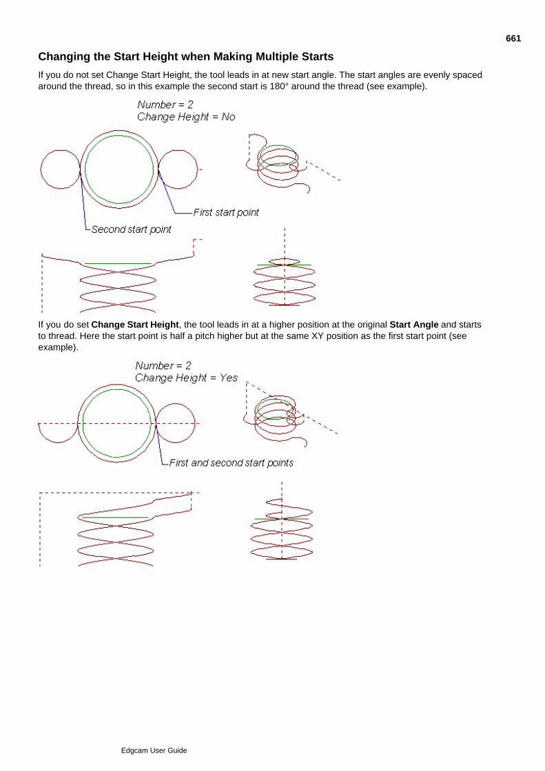
Changing the Start Height when Making Multiple Starts
If you do not set Change Start Height, the tool leads in at new start angle. The start angles are evenly spacedaround the thread, so in this example the second start is 180° around the thread (see example).
If you do set Change Start Height, the tool leads in at a higher position at the original Start Angle and startsto thread. Here the start point is half a pitch higher but at the same XY position as the first start point (seeexample).
661
Edgcam User Guide
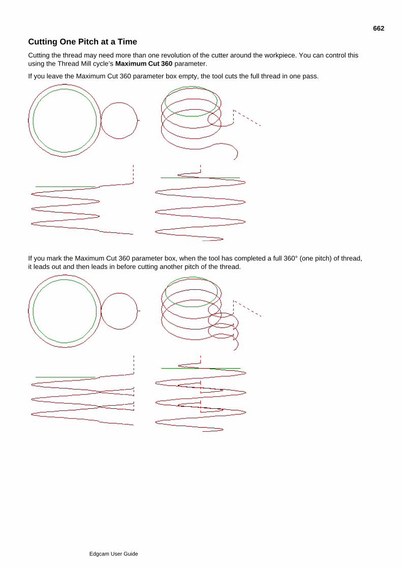
Cutting One Pitch at a Time
Cutting the thread may need more than one revolution of the cutter around the workpiece. You can control thisusing the Thread Mill cycle’s Maximum Cut 360 parameter.
If you leave the Maximum Cut 360 parameter box empty, the tool cuts the full thread in one pass.
If you mark the Maximum Cut 360 parameter box, when the tool has completed a full 360° (one pitch) of thread,it leads out and then leads in before cutting another pitch of the thread.
662
Edgcam User Guide

Leading In and Out
Select the Lead tab to display the lead in and out parameters for the thread.
Select the method of lead in/out using the parameter Type In/Out. The parameter settings are:
Arc1 (Arc Radius)
Direct (Distance)
Arc 2 (Arc Distance)
See Also
Using the Arc Radius (Arc 1) Method
Using the Distance (Direct) Method
Using the Arc Distance (Arc 2) Method
663
Edgcam User Guide

Using the Arc Radius (Arc 1) Method
This brings the tool in tangentially in to the start of the thread, as defined by the parameters Radius In/Out,Angle In/Out and Planar In/Out.
Radius– Defines the radius of the lead move arc as a percentage of the arc geometry you select for the cycle.The default value is 50%.
Angle – Defines the included angle that lead moves pass through. The default value is 180°.
Planar – Specifies whether the lead move should have any vertical movement associated to it. If you do notcheck this box, then the arc lead moves have the same amount of vertical movement as the actual threading.
664
Edgcam User Guide

Using the Distance (Direct) Method
This method brings the tool directly in to the start of the thread.
You must specify the parameter Distance In/Out:
Distance In – Defines the distance from the thread geometry at which the lead move starts.
The tool then feeds into to the piece until it reaches the full cut depth (defined by Thread parameter Depth ofThread).
When the tool has completed a full thread it moves directly away from the workpiece by the value specified inDistance Out parameter.
665
Edgcam User Guide

Using the Arc Distance (Arc 2) Method
This method brings the tool in tangential to the start of the thread, as governed by the parameter DistanceIn/Out.
You must specify this parameter:
Distance – Defines the perpendicular distance at the thread start angle plus 30°, from which the radial leadmove takes place.
666
Edgcam User Guide

How the Thread Mill Cycle Calculates the Feed Rate
Edgecam’s Thread Milling module uses the formula:
Where:
fr = New feed rate
fi = Input feed rate
cthread = Thread (arc selected) circumference
ctool = Toolpath (centre line) circumference
667
Edgcam User Guide
Compensating for the Tool Radius in Thread Milling
Warning - You must obey the rules of the Controller when applying or removing compensation. It is theuser's responsibility to bear in mind the limitations of this facility for each CNC control system.
Compensation – Choose between the Pathtrace and Controller tool radius compensation methods. Thisdetermines how the code generator produces CNC code from this command.
As a tool radius compensation facility is also present in many CNC control systems, you may wish to considerhow best to use these apparently similar facilities.
Controller Compensation
If you select Controller, any code generated for this cycle will be based on the geometry used for the cycle.
The tool radius compensation facility on CNC controllers allows the operator to use tools of different diametersfrom those specified by the programmer, without needing to change the program.
Some users assume a tool of zero diameter within the CNC program and allow the operator to select a suitabletool. This policy has one major disadvantage: the rules for applying and removing tool radius compensation aresometimes complex and you must strictly follow them for the cycle to operate correctly.
Note: If you select Controller compensation, the controller might not create an offset path similar to theEdgecam cycle even if you have specified an equivalent tool radius compensation.
Pathtrace Compensation
If you select Pathtrace, the system will output offset data based on the centre of the tool.
When a CRC factor is used with Pathtrace compensation the straight line move is calculated by multiplying thetool radius with the CRC factor. The start of the compensation move is then calculated as if controllercompensation with a full radius offset were being used. The move length seen on screen and in the NC file willbe adjusted for Pathtrace compensation to show the move from comp start to the Pathtrace offset toolpath.When working with this method, the Canned Cycle option must be checked.
668
Edgcam User Guide

Specifying Tooling Parameters for Thread Mill
These parameters specify the details of the tool to be used in this cycle. The only information the system usesfrom the Toolchange command is the tool diameter.
Number of Teeth – Defines the number of teeth on the tool.
Overlap of Teeth – This parameter defines the number of teeth to be overlapped by this cycle. The overlapcannot exceed the number of teeth on the tool.
Tools with the same number of teeth less the Overlap value produce the same toolpath.
For example, a tool with 6 teeth and an overlap of 2 teeth produces the same toolpath as a tool with 4 teethand no overlap.
Pitch of Tool - Specifies the pitch of the teeth on the tool. It must be equal either the pitch of the thread or thelead of the thread.
The lead of the thread is calculated as follows:
Lead = Pitch of thread x Number of starts
Taper Angle – Specifies the internal angle of the tool, and therefore the angle of the thread to be cut. Seeunder Cutting a Tapered Thread.
Hand of Tool – Selects the hand of tool to be used, and together with Mill Type indicates the direction ofmilling. See Determining the Thread Mill Cut Direction.
669
Edgcam User Guide
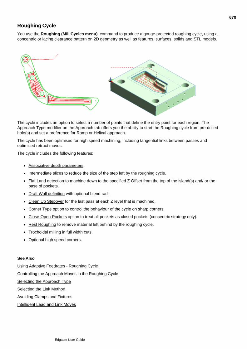
Roughing Cycle
You use the Roughing (Mill Cycles menu) command to produce a gouge-protected roughing cycle, using aconcentric or lacing clearance pattern on 2D geometry as well as features, surfaces, solids and STL models.
The cycle includes an option to select a number of points that define the entry point for each region. TheApproach Type modifier on the Approach tab offers you the ability to start the Roughing cycle from pre-drilledhole(s) and set a preference for Ramp or Helical approach.
The cycle has been optimised for high speed machining, including tangential links between passes andoptimised retract moves.
The cycle includes the following features:
Associative depth parameters.
Intermediate slices to reduce the size of the step left by the roughing cycle.
Flat Land detection to machine down to the specified Z Offset from the top of the island(s) and/ or thebase of pockets.
Draft Wall definition with optional blend radii.
Clean Up Stepover for the last pass at each Z level that is machined.
Corner Type option to control the behaviour of the cycle on sharp corners.
Close Open Pockets option to treat all pockets as closed pockets (concentric strategy only).
Rest Roughing to remove material left behind by the roughing cycle.
Trochoidal milling in full width cuts.
Optional high speed corners.
See Also
Using Adaptive Feedrates - Roughing Cycle
Controlling the Approach Moves in the Roughing Cycle
Selecting the Approach Type
Selecting the Link Method
Avoiding Clamps and Fixtures
Intelligent Lead and Link Moves
670
Edgcam User Guide

Using the Roughing Cycle
Select the Roughing command.1.
In the subsequent Roughing dialog, enter the parameters to set up the cycle. Set Model Type to thegeometry of the shapes you are to machine; Wireframe, Surface or Solid. To machine features, chooseSolid.
You can use wireframe to specify pockets, pockets with islands, male parts (bosses), open pockets.
Note that Model Type is only available with the requisite licence. Without this the setting is effectivelywireframe.
2.
Click OK; the dialog closes so that you can...3.
Follow the prompts at the left hand end of the status bar. You are prompted to:4.
Select the geometry (wireframe, surface, solid or feature - depending on your Model Type setting)that makes up the shape to be machined.
To produce machined non-vertical side walls using wireframe, specify contour wall geometry(optional). See Digitising Contour Walls and Defining Draft Walls.
Select the stock (optional).
Select a containment boundary (optional).
671
Edgcam User Guide
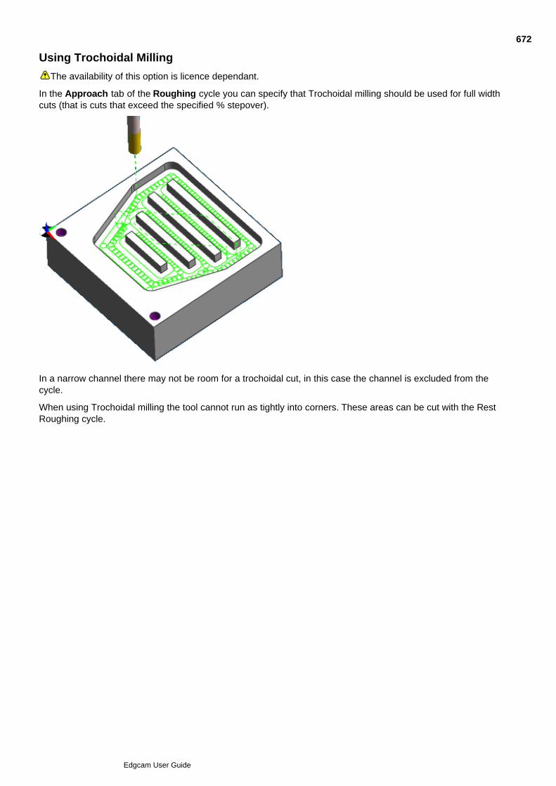
Using Trochoidal Milling
The availability of this option is licence dependant.
In the Approach tab of the Roughing cycle you can specify that Trochoidal milling should be used for full widthcuts (that is cuts that exceed the specified % stepover).
In a narrow channel there may not be room for a trochoidal cut, in this case the channel is excluded from thecycle.
When using Trochoidal milling the tool cannot run as tightly into corners. These areas can be cut with the RestRoughing cycle.
672
Edgcam User Guide
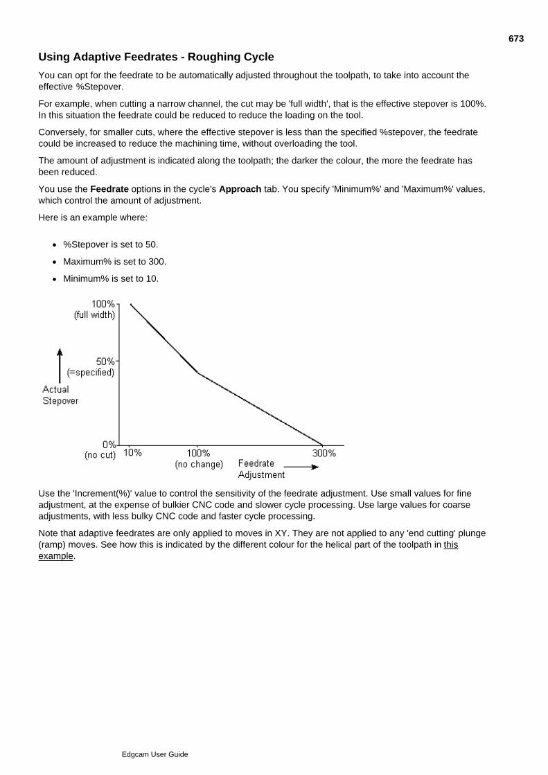
Using Adaptive Feedrates - Roughing Cycle
You can opt for the feedrate to be automatically adjusted throughout the toolpath, to take into account theeffective %Stepover.
For example, when cutting a narrow channel, the cut may be 'full width', that is the effective stepover is 100%.In this situation the feedrate could be reduced to reduce the loading on the tool.
Conversely, for smaller cuts, where the effective stepover is less than the specified %stepover, the feedratecould be increased to reduce the machining time, without overloading the tool.
The amount of adjustment is indicated along the toolpath; the darker the colour, the more the feedrate hasbeen reduced.
You use the Feedrate options in the cycle's Approach tab. You specify 'Minimum%' and 'Maximum%' values,which control the amount of adjustment.
Here is an example where:
%Stepover is set to 50.
Maximum% is set to 300.
Minimum% is set to 10.
Use the 'Increment(%)' value to control the sensitivity of the feedrate adjustment. Use small values for fineadjustment, at the expense of bulkier CNC code and slower cycle processing. Use large values for coarseadjustments, with less bulky CNC code and faster cycle processing.
Note that adaptive feedrates are only applied to moves in XY. They are not applied to any 'end cutting' plunge(ramp) moves. See how this is indicated by the different colour for the helical part of the toolpath in thisexample.
673
Edgcam User Guide

674
Edgcam User Guide

675
Edgcam User Guide
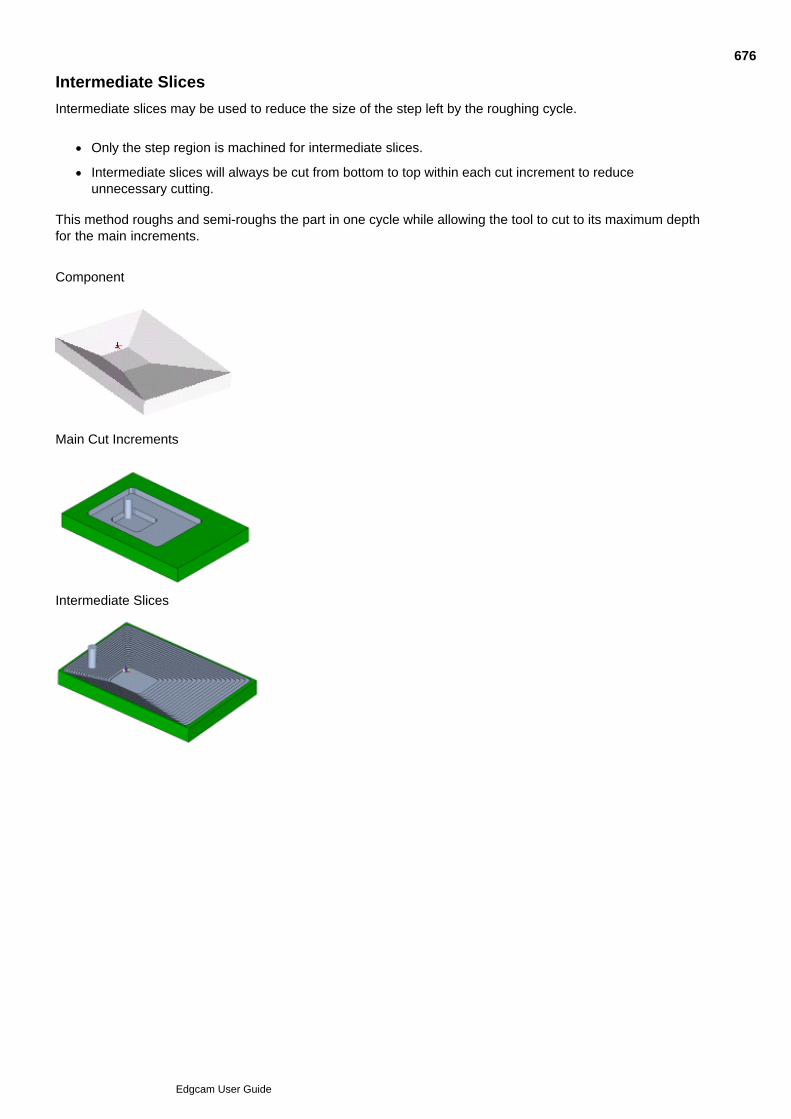
Intermediate Slices
Intermediate slices may be used to reduce the size of the step left by the roughing cycle.
Only the step region is machined for intermediate slices.
Intermediate slices will always be cut from bottom to top within each cut increment to reduceunnecessary cutting.
This method roughs and semi-roughs the part in one cycle while allowing the tool to cut to its maximum depthfor the main increments.
Component
Main Cut Increments
Intermediate Slices
676
Edgcam User Guide
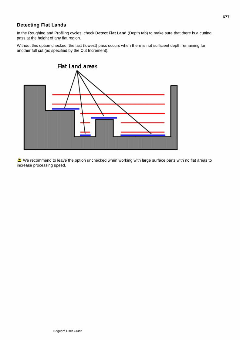
Detecting Flat Lands
In the Roughing and Profiling cycles, check Detect Flat Land (Depth tab) to make sure that there is a cuttingpass at the height of any flat region.
Without this option checked, the last (lowest) pass occurs when there is not sufficient depth remaining foranother full cut (as specified by the Cut Increment).
We recommend to leave the option unchecked when working with large surface parts with no flat areas toincrease processing speed.
677
Edgcam User Guide
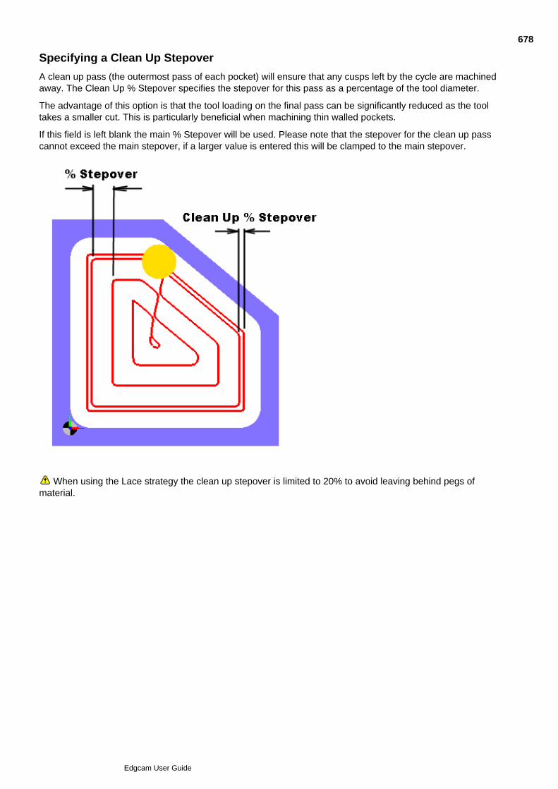
Specifying a Clean Up Stepover
A clean up pass (the outermost pass of each pocket) will ensure that any cusps left by the cycle are machinedaway. The Clean Up % Stepover specifies the stepover for this pass as a percentage of the tool diameter.
The advantage of this option is that the tool loading on the final pass can be significantly reduced as the tooltakes a smaller cut. This is particularly beneficial when machining thin walled pockets.
If this field is left blank the main % Stepover will be used. Please note that the stepover for the clean up passcannot exceed the main stepover, if a larger value is entered this will be clamped to the main stepover.
When using the Lace strategy the clean up stepover is limited to 20% to avoid leaving behind pegs ofmaterial.
678
Edgcam User Guide
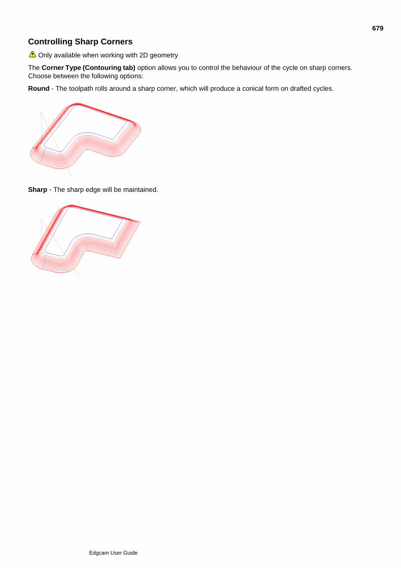
Controlling Sharp Corners
Only available when working with 2D geometry
The Corner Type (Contouring tab) option allows you to control the behaviour of the cycle on sharp corners.Choose between the following options:
Round - The toolpath rolls around a sharp corner, which will produce a conical form on drafted cycles.
Sharp - The sharp edge will be maintained.
679
Edgcam User Guide
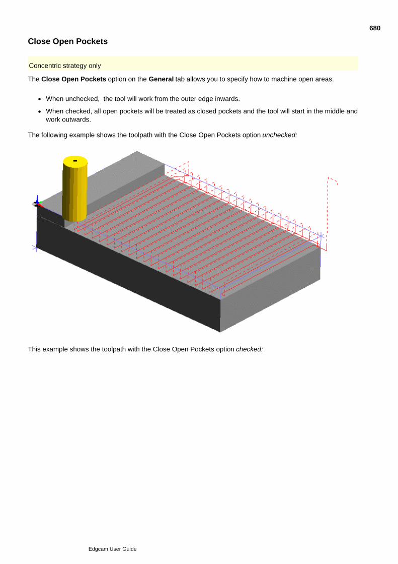
Close Open Pockets
Concentric strategy only
The Close Open Pockets option on the General tab allows you to specify how to machine open areas.
When unchecked, the tool will work from the outer edge inwards.
When checked, all open pockets will be treated as closed pockets and the tool will start in the middle andwork outwards.
The following example shows the toolpath with the Close Open Pockets option unchecked:
This example shows the toolpath with the Close Open Pockets option checked:
680
Edgcam User Guide
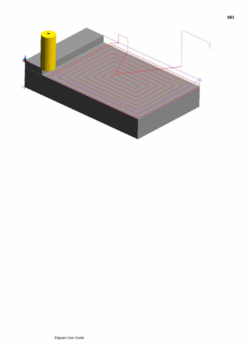
681
Edgcam User Guide
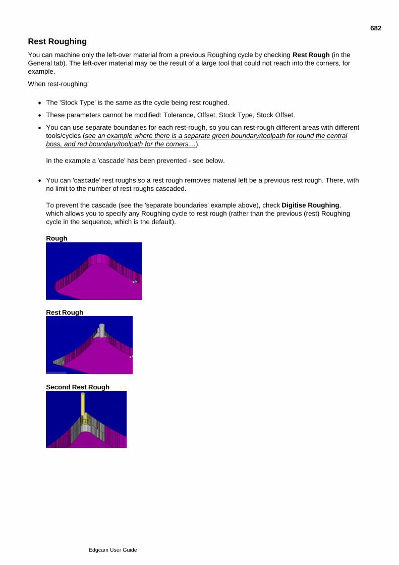
Rest Roughing
You can machine only the left-over material from a previous Roughing cycle by checking Rest Rough (in theGeneral tab). The left-over material may be the result of a large tool that could not reach into the corners, forexample.
When rest-roughing:
The 'Stock Type' is the same as the cycle being rest roughed.
These parameters cannot be modified: Tolerance, Offset, Stock Type, Stock Offset.
You can use separate boundaries for each rest-rough, so you can rest-rough different areas with differenttools/cycles (see an example where there is a separate green boundary/toolpath for round the centralboss, and red boundary/toolpath for the corners....).
In the example a 'cascade' has been prevented - see below.
You can 'cascade' rest roughs so a rest rough removes material left be a previous rest rough. There, withno limit to the number of rest roughs cascaded.
To prevent the cascade (see the 'separate boundaries' example above), check Digitise Roughing,which allows you to specify any Roughing cycle to rest rough (rather than the previous (rest) Roughingcycle in the sequence, which is the default).
Rough
Rest Rough
Second Rest Rough
682
Edgcam User Guide
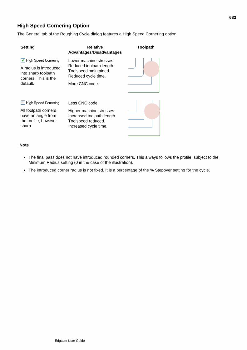
High Speed Cornering Option
The General tab of the Roughing Cycle dialog features a High Speed Cornering option.
Setting RelativeAdvantages/Disadvantages
Toolpath
A radius is introducedinto sharp toolpathcorners. This is thedefault.
Lower machine stresses.Reduced toolpath length.Toolspeed maintained.Reduced cycle time.
More CNC code.
All toolpath cornershave an angle fromthe profile, howeversharp.
Less CNC code.
Higher machine stresses.Increased toolpath length.Toolspeed reduced.Increased cycle time.
Note
The final pass does not have introduced rounded corners. This always follows the profile, subject to theMinimum Radius setting (0 in the case of the illustration).
The introduced corner radius is not fixed. It is a percentage of the % Stepover setting for the cycle.
683
Edgcam User Guide
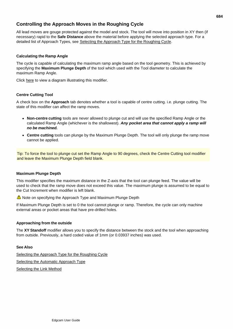
Controlling the Approach Moves in the Roughing Cycle
All lead moves are gouge protected against the model and stock. The tool will move into position in XY then (ifnecessary) rapid to the Safe Distance above the material before applying the selected approach type. For adetailed list of Approach Types, see Selecting the Approach Type for the Roughing Cycle.
Calculating the Ramp Angle
The cycle is capable of calculating the maximum ramp angle based on the tool geometry. This is achieved byspecifying the Maximum Plunge Depth of the tool which used with the Tool diameter to calculate themaximum Ramp Angle.
Click here to view a diagram illustrating this modifier.
Centre Cutting Tool
A check box on the Approach tab denotes whether a tool is capable of centre cutting. i.e. plunge cutting. Thestate of this modifier can affect the ramp moves.
Non-centre cutting tools are never allowed to plunge cut and will use the specified Ramp Angle or thecalculated Ramp Angle (whichever is the shallowest). Any pocket area that cannot apply a ramp willno be machined.
Centre cutting tools can plunge by the Maximum Plunge Depth. The tool will only plunge the ramp movecannot be applied.
Tip: To force the tool to plunge cut set the Ramp Angle to 90 degrees, check the Centre Cutting tool modifierand leave the Maximum Plunge Depth field blank.
Maximum Plunge Depth
This modifier specifies the maximum distance in the Z-axis that the tool can plunge feed. The value will beused to check that the ramp move does not exceed this value. The maximum plunge is assumed to be equal tothe Cut Increment when modifier is left blank.
Note on specifying the Approach Type and Maximum Plunge Depth
If Maximum Plunge Depth is set to 0 the tool cannot plunge or ramp. Therefore, the cycle can only machineexternal areas or pocket areas that have pre-drilled holes.
Approaching from the outside
The XY Standoff modifier allows you to specify the distance between the stock and the tool when approachingfrom outside. Previously, a hard coded value of 1mm (or 0.03937 inches) was used.
See Also
Selecting the Approach Type for the Roughing Cycle
Selecting the Automatic Approach Type
Selecting the Link Method
684
Edgcam User Guide
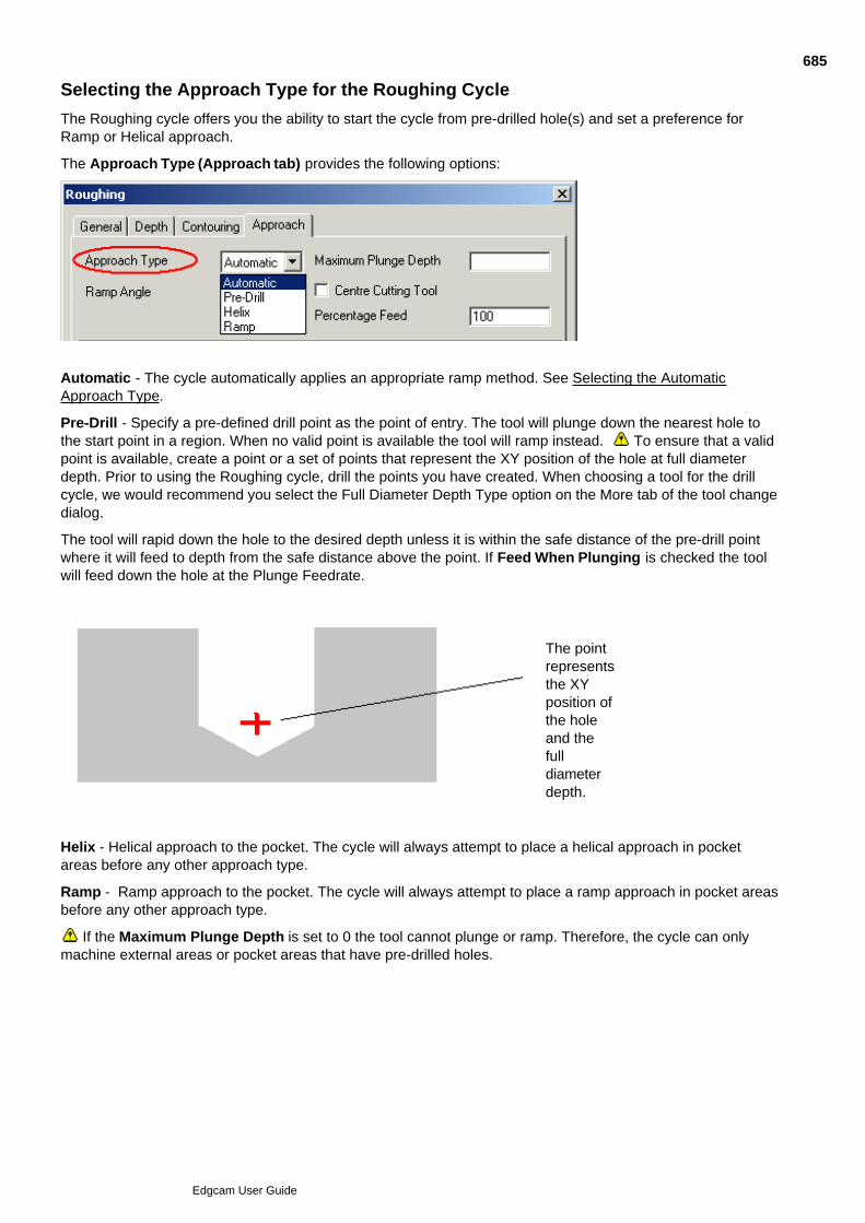
Selecting the Approach Type for the Roughing Cycle
The Roughing cycle offers you the ability to start the cycle from pre-drilled hole(s) and set a preference forRamp or Helical approach.
The Approach Type (Approach tab) provides the following options:
Automatic - The cycle automatically applies an appropriate ramp method. See Selecting the AutomaticApproach Type.
Pre-Drill - Specify a pre-defined drill point as the point of entry. The tool will plunge down the nearest hole tothe start point in a region. When no valid point is available the tool will ramp instead. To ensure that a validpoint is available, create a point or a set of points that represent the XY position of the hole at full diameterdepth. Prior to using the Roughing cycle, drill the points you have created. When choosing a tool for the drillcycle, we would recommend you select the Full Diameter Depth Type option on the More tab of the tool changedialog.
The tool will rapid down the hole to the desired depth unless it is within the safe distance of the pre-drill pointwhere it will feed to depth from the safe distance above the point. If Feed When Plunging is checked the toolwill feed down the hole at the Plunge Feedrate.
The pointrepresentsthe XYposition ofthe holeand thefulldiameterdepth.
Helix - Helical approach to the pocket. The cycle will always attempt to place a helical approach in pocketareas before any other approach type.
Ramp - Ramp approach to the pocket. The cycle will always attempt to place a ramp approach in pocket areasbefore any other approach type.
If the Maximum Plunge Depth is set to 0 the tool cannot plunge or ramp. Therefore, the cycle can onlymachine external areas or pocket areas that have pre-drilled holes.
685
Edgcam User Guide

Selecting the Link Method
Details on Links are included in the help for the Roughing dialog, as shown below (you can also access thishelp by clicking the dialog's Help button):
686
Edgcam User Guide
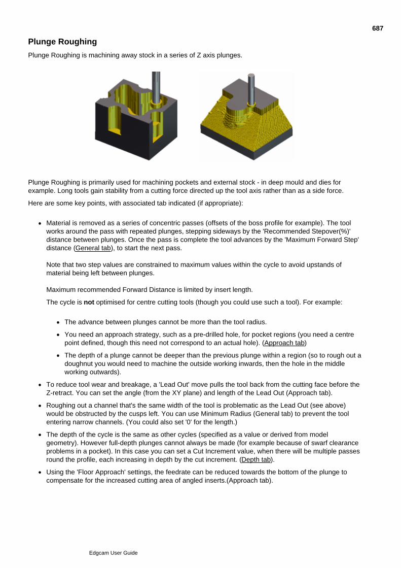
Plunge Roughing
Plunge Roughing is machining away stock in a series of Z axis plunges.
Plunge Roughing is primarily used for machining pockets and external stock - in deep mould and dies forexample. Long tools gain stability from a cutting force directed up the tool axis rather than as a side force.
Here are some key points, with associated tab indicated (if appropriate):
Material is removed as a series of concentric passes (offsets of the boss profile for example). The toolworks around the pass with repeated plunges, stepping sideways by the 'Recommended Stepover(%)'distance between plunges. Once the pass is complete the tool advances by the 'Maximum Forward Step'distance (General tab), to start the next pass.
Note that two step values are constrained to maximum values within the cycle to avoid upstands ofmaterial being left between plunges.
Maximum recommended Forward Distance is limited by insert length.
The cycle is not optimised for centre cutting tools (though you could use such a tool). For example:
The advance between plunges cannot be more than the tool radius.
You need an approach strategy, such as a pre-drilled hole, for pocket regions (you need a centrepoint defined, though this need not correspond to an actual hole). (Approach tab)
The depth of a plunge cannot be deeper than the previous plunge within a region (so to rough out adoughnut you would need to machine the outside working inwards, then the hole in the middleworking outwards).
To reduce tool wear and breakage, a 'Lead Out' move pulls the tool back from the cutting face before theZ-retract. You can set the angle (from the XY plane) and length of the Lead Out (Approach tab).
Roughing out a channel that's the same width of the tool is problematic as the Lead Out (see above)would be obstructed by the cusps left. You can use Minimum Radius (General tab) to prevent the toolentering narrow channels. (You could also set '0' for the length.)
The depth of the cycle is the same as other cycles (specified as a value or derived from modelgeometry). However full-depth plunges cannot always be made (for example because of swarf clearanceproblems in a pocket). In this case you can set a Cut Increment value, when there will be multiple passesround the profile, each increasing in depth by the cut increment. (Depth tab).
Using the 'Floor Approach' settings, the feedrate can be reduced towards the bottom of the plunge tocompensate for the increased cutting area of angled inserts.(Approach tab).
687
Edgcam User Guide

Using the Plunge Roughing Cycle
Select the Plunge Roughing command.1.
In the subsequent Plunge Roughing dialog, enter the parameters to set up the cycle. Set Model Type tothe geometry of the shapes you are to machine; Wireframe, Surface or Solid. To machine features,choose Solid.
You can use wireframe to specify pockets, pockets with islands, male parts (bosses), open pockets.
Note that Model Type is only available with the requisite licence. Without this the setting is effectivelywireframe.
2.
Click OK; the dialog closes so that you can...3.
Follow the prompts at the left hand end of the status bar. You are prompted to:4.
Select the geometry (wireframe, surface, solid or feature - depending on your Model Type setting)that makes up the shape to be machined.
To produce machined non-vertical side walls using wireframe, specify contour wall geometry(optional). See Digitising Contour Walls and Defining Draft Walls.
Select the stock (optional).
Select a containment boundary (optional).
Note that the Containment Boundary profile must not be coincident with, or fully contained within, theStock profile. (That is with the profiles projected onto the XY plane - equivalent to looking at theprofiles in the Z direction.)
688
Edgcam User Guide

689
Edgcam User Guide

690
Edgcam User Guide
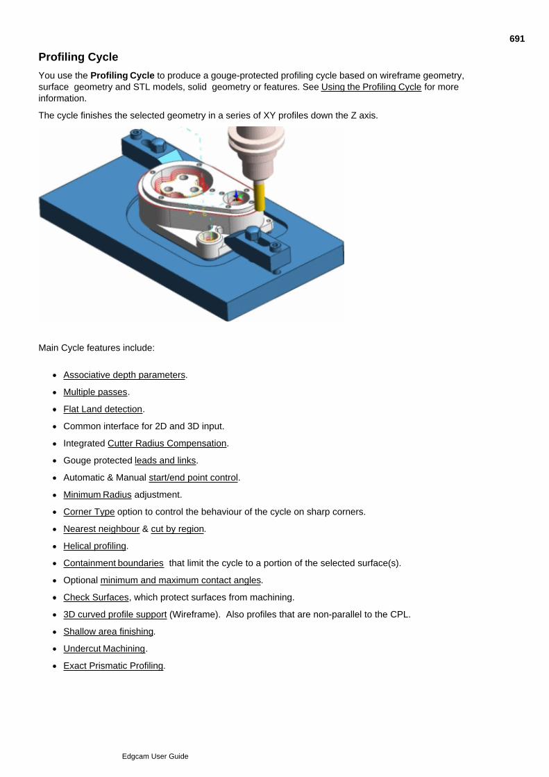
Profiling Cycle
You use the Profiling Cycle to produce a gouge-protected profiling cycle based on wireframe geometry,surface geometry and STL models, solid geometry or features. See Using the Profiling Cycle for moreinformation.
The cycle finishes the selected geometry in a series of XY profiles down the Z axis.
Main Cycle features include:
Associative depth parameters.
Multiple passes.
Flat Land detection.
Common interface for 2D and 3D input.
Integrated Cutter Radius Compensation.
Gouge protected leads and links.
Automatic & Manual start/end point control.
Minimum Radius adjustment.
Corner Type option to control the behaviour of the cycle on sharp corners.
Nearest neighbour & cut by region.
Helical profiling.
Containment boundaries that limit the cycle to a portion of the selected surface(s).
Optional minimum and maximum contact angles.
Check Surfaces, which protect surfaces from machining.
3D curved profile support (Wireframe). Also profiles that are non-parallel to the CPL.
Shallow area finishing.
Undercut Machining.
Exact Prismatic Profiling.
691
Edgcam User Guide

Clipping to Depth.
As this Profiling cycle includes 2D options, it effectively supercedes the old Profile cycle. We recommend theProfiling cycle as it offers more features and has a user interface that is consistent with other recent cycles.
692
Edgcam User Guide
Using the Profiling Cycle
Select the Profiling command.1.
In the subsequent Profiling dialog, set the modifiers to set up the cycle. Set Model Type to the geometryof the shapes you are to machine; Wireframe, Surface or Solid. To machine features, choose Solid.
You can use wireframe to specify pockets, pockets with islands, male parts (bosses), open pockets.
Note that Model Type is only available with the requisite licence. Without this the setting is effectivelywireframe.
To machine profiles that curve in three dimensions, or that have a plane that is non-parallel to the CPL,check 3D Profiling (General tab).
2.
Click OK; the dialog closes so that you can...3.
Follow the prompts at the left hand end of the status bar. You are prompted to:4.
Select the geometry (wireframe, surface, solid or feature - depending on your Model Type setting)that makes up the shape to be machined.
Specify start and end points.
To produce machined non-vertical side walls using wireframe, specify contour wall geometry(optional). See Digitising Contour Walls and Defining Draft Walls.
Select a containment boundary (optional).
Note that if you are profiling multiple wireframe profiles and the tool is too large to fit between them, then theCompensation setting of Geometry is overridden (if set) and the tool centre line is output. You see the errormessage 'Cannot apply geometry. Tool too large to fit between profiles'. See this illustrated.
693
Edgcam User Guide
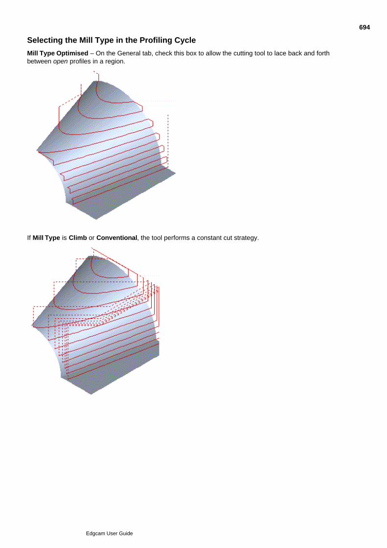
Selecting the Mill Type in the Profiling Cycle
Mill Type Optimised – On the General tab, check this box to allow the cutting tool to lace back and forthbetween open profiles in a region.
If Mill Type is Climb or Conventional, the tool performs a constant cut strategy.
694
Edgcam User Guide

Note: This is not available when 3D curve profiling.
695
Edgcam User Guide

696
Edgcam User Guide
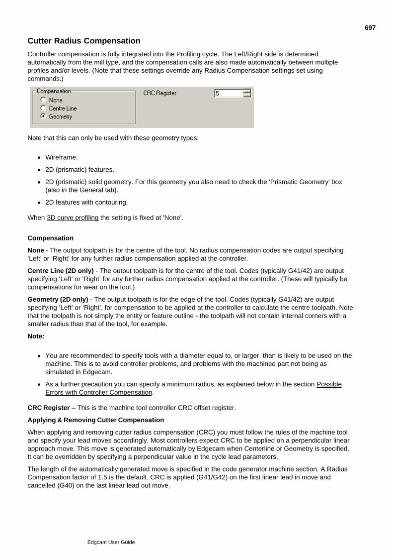
Cutter Radius Compensation
Controller compensation is fully integrated into the Profiling cycle. The Left/Right side is determinedautomatically from the mill type, and the compensation calls are also made automatically between multipleprofiles and/or levels. (Note that these settings override any Radius Compensation settings set usingcommands.)
Note that this can only be used with these geometry types:
Wireframe.
2D (prismatic) features.
2D (prismatic) solid geometry. For this geometry you also need to check the 'Prismatic Geometry' box(also in the General tab).
2D features with contouring.
When 3D curve profiling the setting is fixed at 'None'.
Compensation
None - The output toolpath is for the centre of the tool. No radius compensation codes are output specifying‘Left’ or ‘Right’ for any further radius compensation applied at the controller.
Centre Line (2D only) - The output toolpath is for the centre of the tool. Codes (typically G41/42) are outputspecifying ‘Left’ or ‘Right’ for any further radius compensation applied at the controller. (These will typically becompensations for wear on the tool.)
Geometry (2D only) - The output toolpath is for the edge of the tool. Codes (typically G41/42) are outputspecifying ‘Left’ or ‘Right’, for compensation to be applied at the controller to calculate the centre toolpath. Notethat the toolpath is not simply the entity or feature outline - the toolpath will not contain internal corners with asmaller radius than that of the tool, for example.
Note:
You are recommended to specify tools with a diameter equal to, or larger, than is likely to be used on themachine. This is to avoid controller problems, and problems with the machined part not being assimulated in Edgecam.
As a further precaution you can specify a minimum radius, as explained below in the section PossibleErrors with Controller Compensation.
CRC Register – This is the machine tool controller CRC offset register.
Applying & Removing Cutter Compensation
When applying and removing cutter radius compensation (CRC) you must follow the rules of the machine tooland specify your lead moves accordingly. Most controllers expect CRC to be applied on a perpendicular linearapproach move. This move is generated automatically by Edgecam when Centerline or Geometry is specified.It can be overridden by specifying a perpendicular value in the cycle lead parameters.
The length of the automatically generated move is specified in the code generator machine section. A RadiusCompensation factor of 1.5 is the default. CRC is applied (G41/G42) on the first linear lead in move andcancelled (G40) on the last linear lead out move.
697
Edgcam User Guide
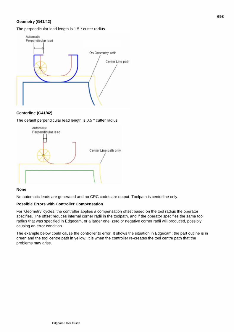
Geometry (G41/42)
The perpendicular lead length is 1.5 * cutter radius.
Centerline (G41/42)
The default perpendicular lead length is 0.5 * cutter radius.
None
No automatic leads are generated and no CRC codes are output. Toolpath is centerline only.
Possible Errors with Controller Compensation
For 'Geometry' cycles, the controller applies a compensation offset based on the tool radius the operatorspecifies. The offset reduces internal corner radii in the toolpath, and if the operator specifies the same toolradius that was specified in Edgecam, or a larger one, zero or negative corner radii will produced, possiblycausing an error condition.
The example below could cause the controller to error. It shows the situation in Edgecam; the part outline is ingreen and the tool centre path in yellow. It is when the controller re-creates the tool centre path that theproblems may arise.
698
Edgcam User Guide
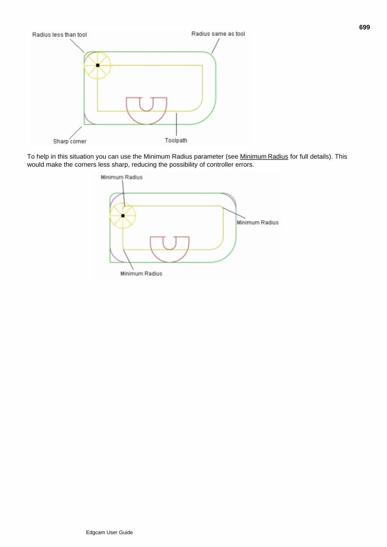
To help in this situation you can use the Minimum Radius parameter (see Minimum Radius for full details). Thiswould make the corners less sharp, reducing the possibility of controller errors.
699
Edgcam User Guide
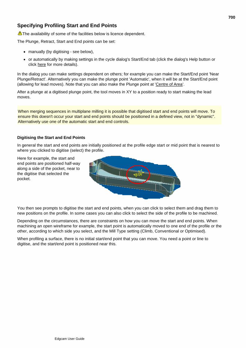
Specifying Profiling Start and End Points
The availability of some of the facilities below is licence dependent.
The Plunge, Retract, Start and End points can be set:
manually (by digitising - see below),
or automatically by making settings in the cycle dialog's Start/End tab (click the dialog's Help button orclick here for more details).
In the dialog you can make settings dependent on others; for example you can make the Start/End point 'NearPlunge/Retract'. Alternatively you can make the plunge point 'Automatic', when it will be at the Start/End point(allowing for lead moves). Note that you can also make the Plunge point at 'Centre of Area'.
After a plunge at a digitised plunge point, the tool moves in XY to a position ready to start making the leadmoves.
When merging sequences in multiplane milling it is possible that digitised start and end points will move. Toensure this doesn't occur your start and end points should be positioned in a defined view, not in "dynamic".Alternatively use one of the automatic start and end controls.
Digitising the Start and End Points
In general the start and end points are initially positioned at the profile edge start or mid point that is nearest towhere you clicked to digitise (select) the profile.
Here for example, the start andend points are positioned half-wayalong a side of the pocket, near tothe digitise that selected thepocket.
You then see prompts to digitise the start and end points, when you can click to select them and drag them tonew positions on the profile. In some cases you can also click to select the side of the profile to be machined.
Depending on the circumstances, there are constraints on how you can move the start and end points. Whenmachining an open wireframe for example, the start point is automatically moved to one end of the profile or theother, according to which side you select, and the Mill Type setting (Climb, Conventional or Optimised).
When profiling a surface, there is no initial start/end point that you can move. You need a point or line todigitise, and the start/end point is positioned near this.
700
Edgcam User Guide
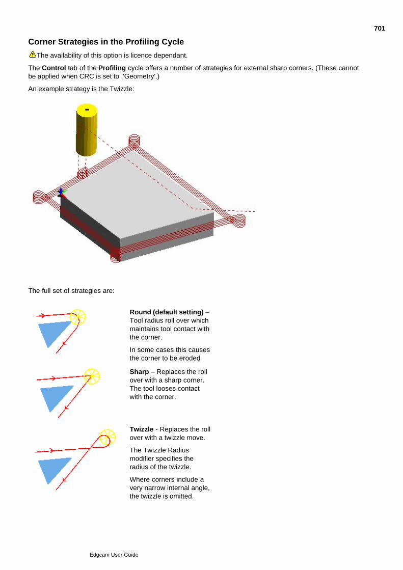
Corner Strategies in the Profiling Cycle
The availability of this option is licence dependant.
The Control tab of the Profiling cycle offers a number of strategies for external sharp corners. (These cannotbe applied when CRC is set to 'Geometry'.)
An example strategy is the Twizzle:
The full set of strategies are:
Round (default setting) –Tool radius roll over whichmaintains tool contact withthe corner.
In some cases this causesthe corner to be eroded
Sharp – Replaces the rollover with a sharp corner.The tool looses contactwith the corner.
Twizzle - Replaces the rollover with a twizzle move.
The Twizzle Radiusmodifier specifies theradius of the twizzle.
Where corners include avery narrow internal angle,the twizzle is omitted.
701
Edgcam User Guide

High Speed - Replacesthe roll over with arounded corner with aradius of 75% of the tool'sradius. This helpsmaintain tool velocity.
For the corner strategy to take effect on 2D Profiling the Corner Type (Contouring tab) modifier must beset to Sharp.
702
Edgcam User Guide

703
Edgcam User Guide
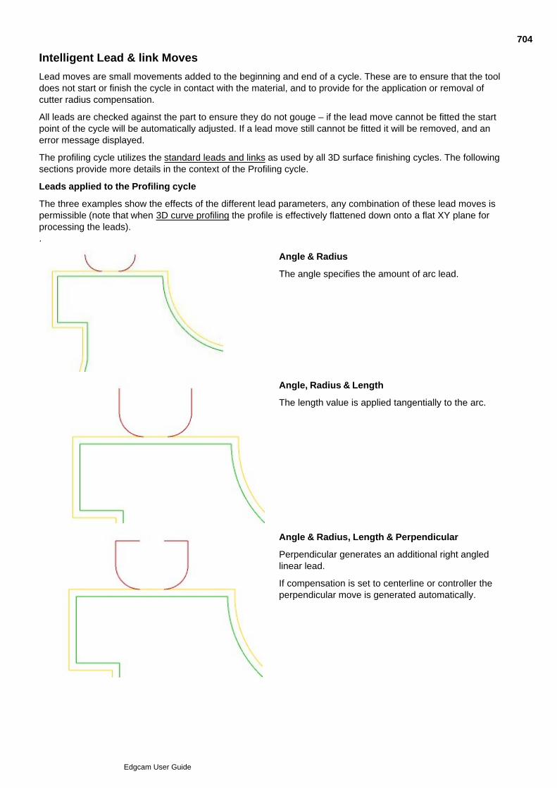
Intelligent Lead & link Moves
Lead moves are small movements added to the beginning and end of a cycle. These are to ensure that the tooldoes not start or finish the cycle in contact with the material, and to provide for the application or removal ofcutter radius compensation.
All leads are checked against the part to ensure they do not gouge – if the lead move cannot be fitted the startpoint of the cycle will be automatically adjusted. If a lead move still cannot be fitted it will be removed, and anerror message displayed.
The profiling cycle utilizes the standard leads and links as used by all 3D surface finishing cycles. The followingsections provide more details in the context of the Profiling cycle.
Leads applied to the Profiling cycle
The three examples show the effects of the different lead parameters, any combination of these lead moves ispermissible (note that when 3D curve profiling the profile is effectively flattened down onto a flat XY plane forprocessing the leads)..
Angle & Radius
The angle specifies the amount of arc lead.
Angle, Radius & Length
The length value is applied tangentially to the arc.
Angle & Radius, Length & Perpendicular
Perpendicular generates an additional right angledlinear lead.
If compensation is set to centerline or controller theperpendicular move is generated automatically.
704
Edgcam User Guide
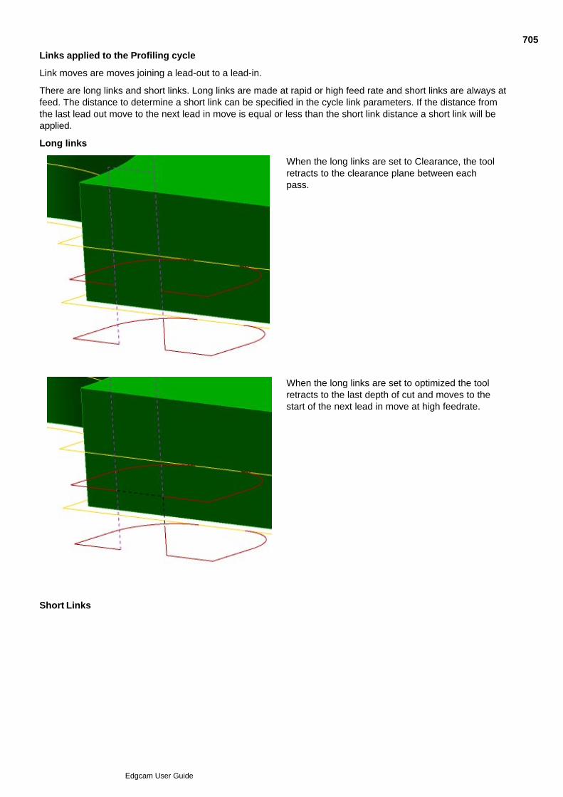
Links applied to the Profiling cycle
Link moves are moves joining a lead-out to a lead-in.
There are long links and short links. Long links are made at rapid or high feed rate and short links are always atfeed. The distance to determine a short link can be specified in the cycle link parameters. If the distance fromthe last lead out move to the next lead in move is equal or less than the short link distance a short link will beapplied.
Long links
When the long links are set to Clearance, the toolretracts to the clearance plane between eachpass.
When the long links are set to optimized the toolretracts to the last depth of cut and moves to thestart of the next lead in move at high feedrate.
Short Links
705
Edgcam User Guide
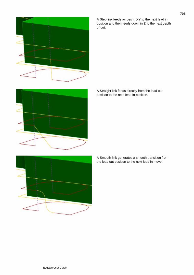
A Step link feeds across in XY to the next lead inposition and then feeds down in Z to the next depthof cut.
A Straight link feeds directly from the lead outposition to the next lead in position.
A Smooth link generates a smooth transition fromthe lead out position to the next lead in move.
706
Edgcam User Guide
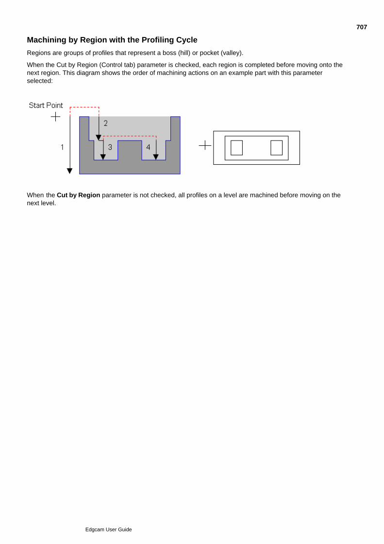
Machining by Region with the Profiling Cycle
Regions are groups of profiles that represent a boss (hill) or pocket (valley).
When the Cut by Region (Control tab) parameter is checked, each region is completed before moving onto thenext region. This diagram shows the order of machining actions on an example part with this parameterselected:
When the Cut by Region parameter is not checked, all profiles on a level are machined before moving on thenext level.
707
Edgcam User Guide

Nearest Neighbour
Please note that the availability of this option is licence dependant.
The profiles will be machined in an order to give the shortest path based on always machining the next nearestprofile. If this is not checked the profiles will be machined in the order they were digitized.
This is not applicable to 3D, since all toolpaths are nearest neighbour. The digitised order has no influence on a3D toolpath.
708
Edgcam User Guide

Helical Profiling
To implement Helical Profiling check Helical in the cycle's Depth tab.
A spiral toolpath is generated ensuring the tool is always in contact with the material eliminating potential markson the component made through leading in and leading out.
This has the additional benefit of reduced cycle times because lead moves are not required at each level. Thepitch of the helix is controlled by the cut increment.
You can use the option to implement Helical Boring.
Check NC Output Smoothing in the General tab for helical arc moves (typically G2/G3) in the NC output.Helical Arcs must be supported in the code generator (in the Code Wizard you set the 'Helical Arc Capability'machine parameter). We only recommend this for vertically-walled components to prevent problems caused bythe constantly changing arc radius.
Note: Helical Profiling is not available when 3D curve profiling.
709
Edgcam User Guide
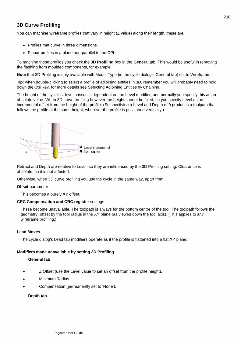
3D Curve Profiling
You can machine wireframe profiles that vary in height (Z value) along their length, these are:
Profiles that curve in three dimensions.
Planar profiles in a plane non-parallel to the CPL.
To machine these profiles you check the 3D Profiling box in the General tab. This would be useful in removingthe flashing from moulded components, for example.
Note that 3D Profiling is only available with Model Type (in the cycle dialog's General tab) set to Wireframe.
Tip: when double-clicking to select a profile of adjoining entities in 3D, remember you will probably need to holddown the Ctrl key, for more details see Selecting Adjoining Entities by Chaining.
The height of the cycle's z-level passes is dependent on the Level modifier, and normally you specify this as anabsolute value. When 3D curve profiling however the height cannot be fixed, so you specify Level as anincremental offset from the height of the profile. (So specifying a Level and Depth of 0 produces a toolpath thatfollows the profile at the same height, wherever the profile is positioned vertically.)
Retract and Depth are relative to Level, so they are influenced by the 3D Profiling setting. Clearance isabsolute, so it is not affected.
Otherwise, when 3D curve profiling you use the cycle in the same way, apart from:
Offset parameter
This becomes a purely XY offset.
CRC Compensation and CRC register settings
These become unavailable. The toolpath is always for the bottom centre of the tool. The toolpath follows thegeometry, offset by the tool radius in the XY plane (as viewed down the tool axis). (This applies to anywireframe profiling.)
Lead Moves
The cycle dialog's Lead tab modifiers operate as if the profile is flattened into a flat XY plane.
Modifiers made unavailable by setting 3D Profiling
General tab
Z Offset (use the Level value to set an offset from the profile height).
Minimum Radius.
Compensation (permanently set to 'None').
Depth tab
710
Edgcam User Guide

Cusp Height
Helical
Detect Flat Lands.
Control tab
All the modifiers.
Start/End tab
Start
End
Overlap
Contouring
All the modifiers
711
Edgcam User Guide
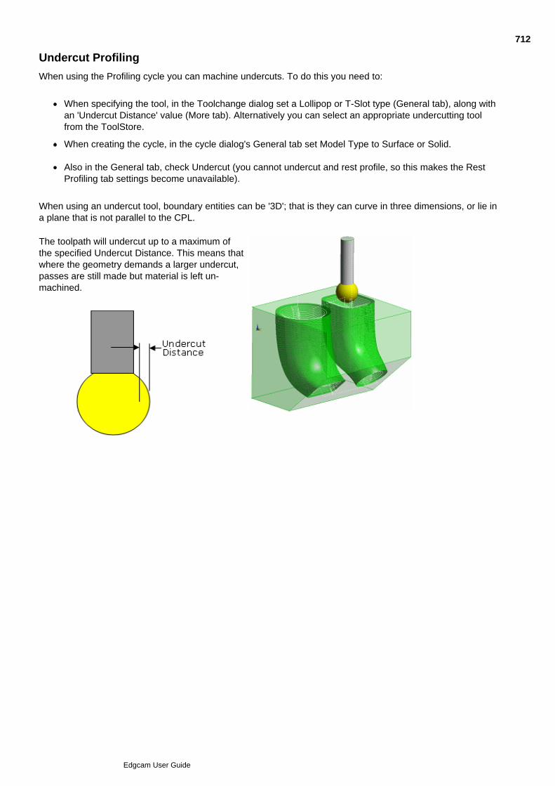
Undercut Profiling
When using the Profiling cycle you can machine undercuts. To do this you need to:
When specifying the tool, in the Toolchange dialog set a Lollipop or T-Slot type (General tab), along withan 'Undercut Distance' value (More tab). Alternatively you can select an appropriate undercutting toolfrom the ToolStore.
When creating the cycle, in the cycle dialog's General tab set Model Type to Surface or Solid.
Also in the General tab, check Undercut (you cannot undercut and rest profile, so this makes the RestProfiling tab settings become unavailable).
When using an undercut tool, boundary entities can be '3D'; that is they can curve in three dimensions, or lie ina plane that is not parallel to the CPL.
The toolpath will undercut up to a maximum ofthe specified Undercut Distance. This means thatwhere the geometry demands a larger undercut,passes are still made but material is left un-machined.
712
Edgcam User Guide
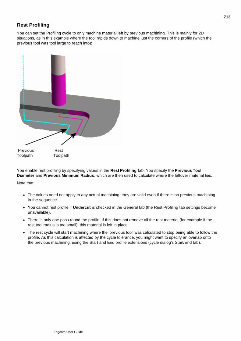
Rest Profiling
You can set the Profiling cycle to only machine material left by previous machining. This is mainly for 2Dsituations, as in this example where the tool rapids down to machine just the corners of the profile (which theprevious tool was tool large to reach into):
Previous RestToolpath Toolpath
You enable rest profiling by specifying values in the Rest Profiling tab. You specify the Previous ToolDiameter and Previous Minimum Radius, which are then used to calculate where the leftover material lies.
Note that:
The values need not apply to any actual machining, they are valid even if there is no previous machiningin the sequence.
You cannot rest profile if Undercut is checked in the General tab (the Rest Profiling tab settings becomeunavailable).
There is only one pass round the profile. If this does not remove all the rest material (for example if therest tool radius is too small), this material is left in place.
The rest cycle will start machining where the 'previous tool' was calculated to stop being able to follow theprofile. As this calculation is affected by the cycle tolerance, you might want to specify an overlap ontothe previous machining, using the Start and End profile extensions (cycle dialog's Start/End tab).
713
Edgcam User Guide
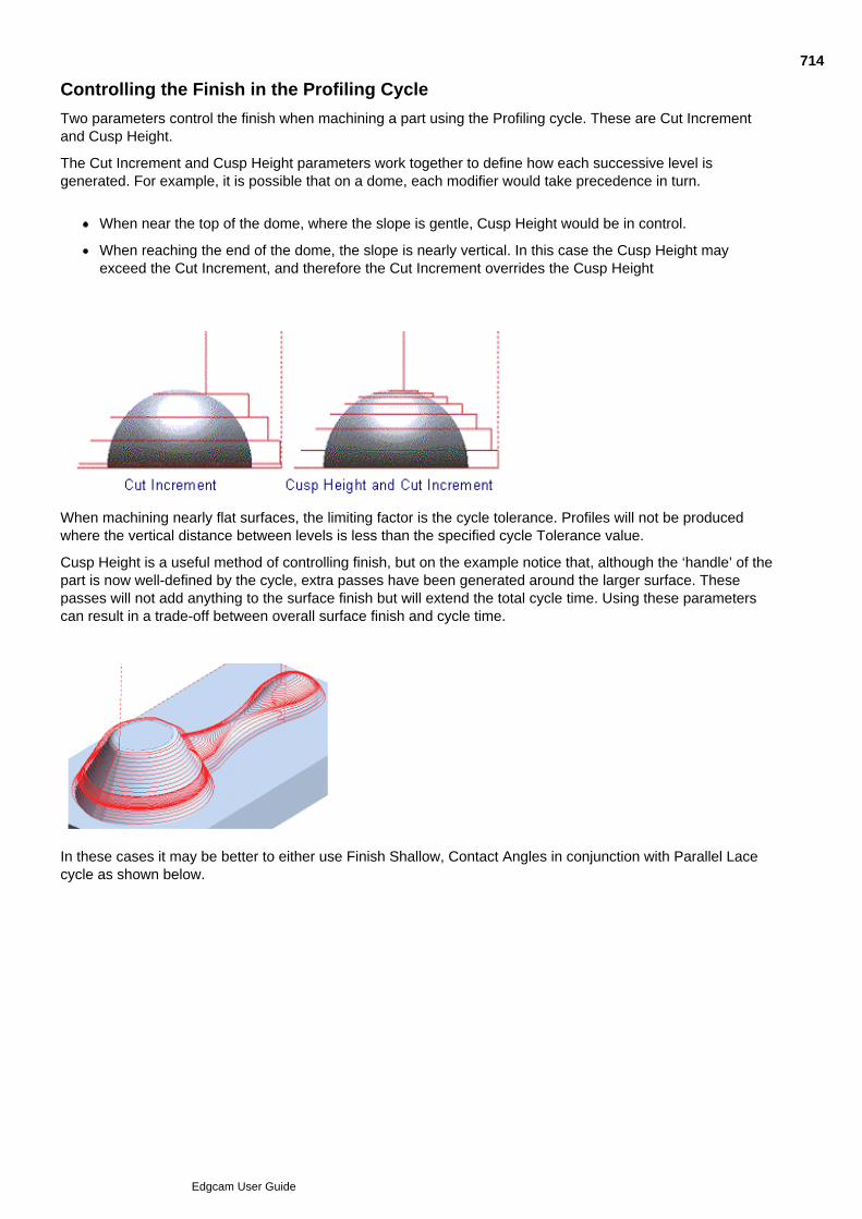
Controlling the Finish in the Profiling Cycle
Two parameters control the finish when machining a part using the Profiling cycle. These are Cut Incrementand Cusp Height.
The Cut Increment and Cusp Height parameters work together to define how each successive level isgenerated. For example, it is possible that on a dome, each modifier would take precedence in turn.
When near the top of the dome, where the slope is gentle, Cusp Height would be in control.
When reaching the end of the dome, the slope is nearly vertical. In this case the Cusp Height mayexceed the Cut Increment, and therefore the Cut Increment overrides the Cusp Height
When machining nearly flat surfaces, the limiting factor is the cycle tolerance. Profiles will not be producedwhere the vertical distance between levels is less than the specified cycle Tolerance value.
Cusp Height is a useful method of controlling finish, but on the example notice that, although the ‘handle’ of thepart is now well-defined by the cycle, extra passes have been generated around the larger surface. Thesepasses will not add anything to the surface finish but will extend the total cycle time. Using these parameterscan result in a trade-off between overall surface finish and cycle time.
In these cases it may be better to either use Finish Shallow, Contact Angles in conjunction with Parallel Lacecycle as shown below.
714
Edgcam User Guide

See Also
Finish Shallow Areas
Using Contact Angles
Using Boundaries
715
Edgcam User Guide

Prismatic Geometry from Solids
Enable the Prismatic Geometry optionto profile prismatic areas of parts withmore accuracy and less CNC code.
Edgecam detects areas of prismaticgeometry in surface and solids basedparts. This geometry is then insertedinto the toolpath directly as arcmoves, rather than as a series ofstraight line approximations (as it isfor areas of more complex geometry).
(Note that this is a similar function to the Line Arc and Spline settings for NC Output Smoothing. However theNC Output settings replace straight line approximations once they have appeared in the toolpath, rather than'at source'.)
The option increases processing time, so only enable it if your part contains some prismatic geometry. Alsonote the option has no effect on some types of prismatic geometry - see Prismatic Geometry Limitations.
To see which are the prismatic areas of your geometry, you could check Options menu Preferences Solids tab Render by Geometry Type. For more details click the Help button in the Preferences dialog.
716
Edgcam User Guide
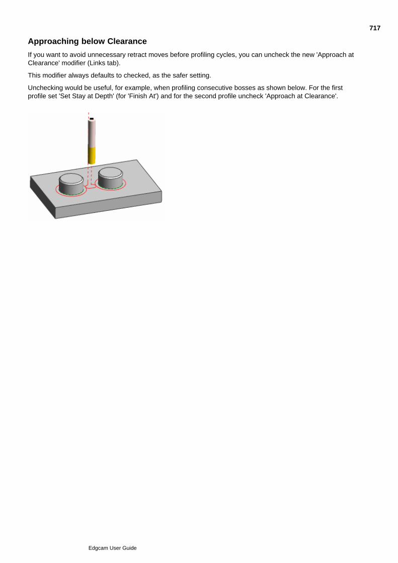
Approaching below Clearance
If you want to avoid unnecessary retract moves before profiling cycles, you can uncheck the new 'Approach atClearance' modifier (Links tab).
This modifier always defaults to checked, as the safer setting.
Unchecking would be useful, for example, when profiling consecutive bosses as shown below. For the firstprofile set 'Set Stay at Depth' (for 'Finish At') and for the second profile uncheck 'Approach at Clearance'.
717
Edgcam User Guide

Profiling dialog - Control tab
Here are details on the settings in the Profiling dialog, Control tab (you can also access this help by clicking theHelp button in the dialog):
718
Edgcam User Guide

Finishing Shallow Areas
As the surface becomes more horizontal, the Z-level passes become more spaced out (looking at right-anglesonto the surface), this may lead to a non-uniform finish.
The cycle gives you options for inserting extra passes to correct this.
You use the Finish Shallow Areas option on the cycle's Control tab; you can (licence permitting):
Take no special measures for the shallow areas (choose 'None').
Finish shallow areas with a 'Constant Cusp' strategy.
The extra passes are created by projecting the Z level passes with an offset calculated to give a constantcusp height. The extra passes are stopped if and when they meet a Z level pass.
Finish shallow areas with a 'Projected' strategy.
The extra passes are created by projecting the Z level passes across the surface with a constant XYoffset (as you'd see looking from the top), which is defined by the %Stepover value. The extra passesare stopped if and when they meet a Z level pass.
Note that for the extra passes, the 3D toolpath spacing (as you'd see looking at right angles onto thesurface) gets smaller as the surface gets flatter. This is the opposite of the Z-level areas, where the 3Dspacing gets larger as the surface gets flatter.
Machine shallow areas with a 'Parallel' (lace) strategy (generally for use on flat faces of prismatic typeparts).
All these strategies use the %Stepover parameter.
For the shallow areas the 'Type' lead parameter is forced to Vertical.
Constant Cusp Strategy Example
Projection Strategy Example One
Projection Strategy Example Two (Zoom)
719
Edgcam User Guide
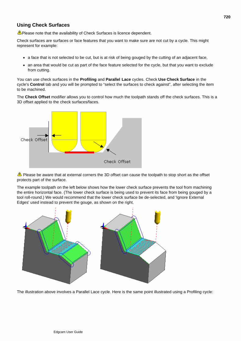
Using Check Surfaces
Please note that the availability of Check Surfaces is licence dependent.
Check surfaces are surfaces or face features that you want to make sure are not cut by a cycle. This mightrepresent for example:
a face that is not selected to be cut, but is at risk of being gouged by the cutting of an adjacent face,
an area that would be cut as part of the face feature selected for the cycle, but that you want to excludefrom cutting.
You can use check surfaces in the Profiling and Parallel Lace cycles. Check Use Check Surface in thecycle's Control tab and you will be prompted to “select the surfaces to check against”, after selecting the itemto be machined.
The Check Offset modifier allows you to control how much the toolpath stands off the check surfaces. This is a3D offset applied to the check surfaces/faces.
Please be aware that at external corners the 3D offset can cause the toolpath to stop short as the offsetprotects part of the surface.
The example toolpath on the left below shows how the lower check surface prevents the tool from machiningthe entire horizontal face. (The lower check surface is being used to prevent its face from being gouged by atool roll-round.) We would recommend that the lower check surface be de-selected, and 'Ignore ExternalEdges' used instead to prevent the gouge, as shown on the right.
The illustration above involves a Parallel Lace cycle. Here is the same point illustrated using a Profiling cycle:
720
Edgcam User Guide
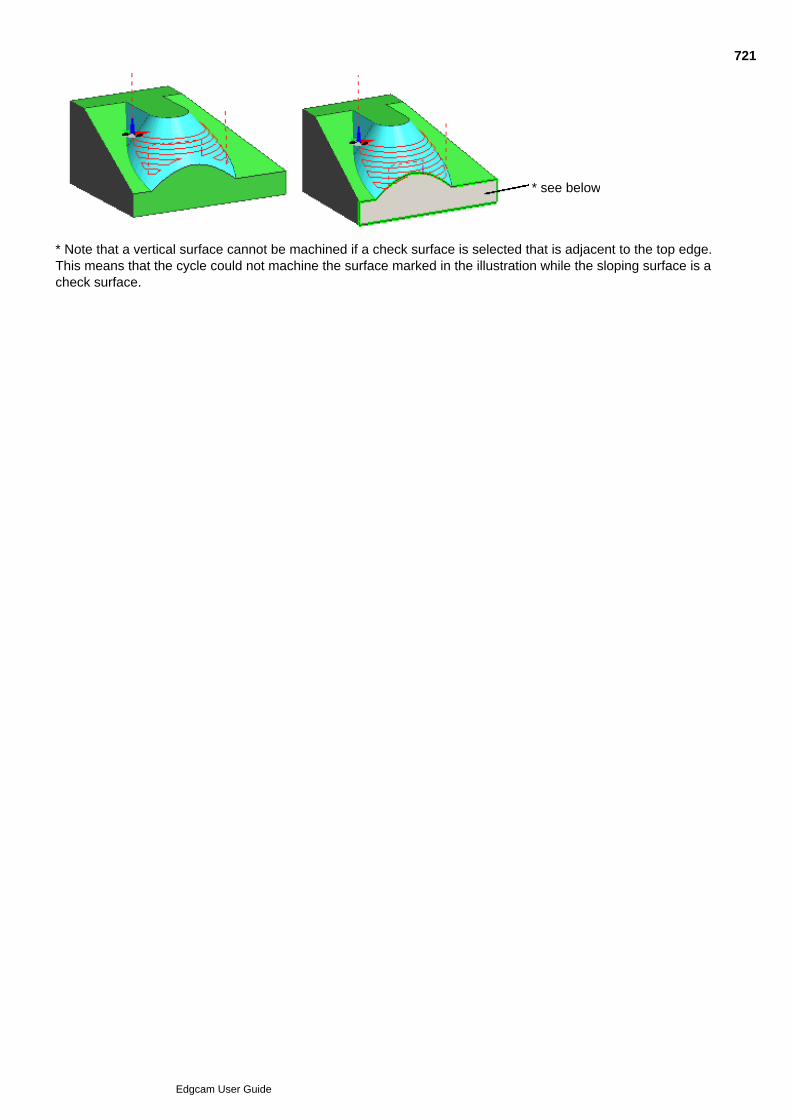
* see below
* Note that a vertical surface cannot be machined if a check surface is selected that is adjacent to the top edge.This means that the cycle could not machine the surface marked in the illustration while the sloping surface is acheck surface.
721
Edgcam User Guide
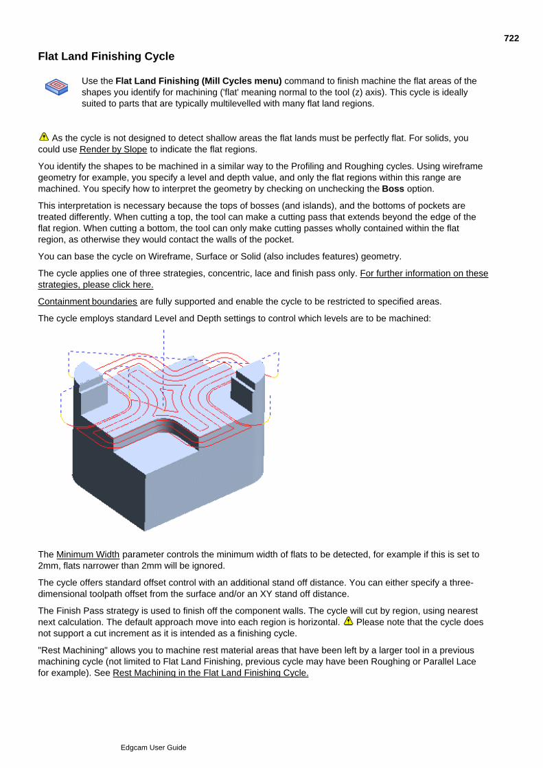
Flat Land Finishing Cycle
Use the Flat Land Finishing (Mill Cycles menu) command to finish machine the flat areas of theshapes you identify for machining ('flat' meaning normal to the tool (z) axis). This cycle is ideallysuited to parts that are typically multilevelled with many flat land regions.
As the cycle is not designed to detect shallow areas the flat lands must be perfectly flat. For solids, youcould use Render by Slope to indicate the flat regions.
You identify the shapes to be machined in a similar way to the Profiling and Roughing cycles. Using wireframegeometry for example, you specify a level and depth value, and only the flat regions within this range aremachined. You specify how to interpret the geometry by checking on unchecking the Boss option.
This interpretation is necessary because the tops of bosses (and islands), and the bottoms of pockets aretreated differently. When cutting a top, the tool can make a cutting pass that extends beyond the edge of theflat region. When cutting a bottom, the tool can only make cutting passes wholly contained within the flatregion, as otherwise they would contact the walls of the pocket.
You can base the cycle on Wireframe, Surface or Solid (also includes features) geometry.
The cycle applies one of three strategies, concentric, lace and finish pass only. For further information on thesestrategies, please click here.
Containment boundaries are fully supported and enable the cycle to be restricted to specified areas.
The cycle employs standard Level and Depth settings to control which levels are to be machined:
The Minimum Width parameter controls the minimum width of flats to be detected, for example if this is set to2mm, flats narrower than 2mm will be ignored.
The cycle offers standard offset control with an additional stand off distance. You can either specify a three-dimensional toolpath offset from the surface and/or an XY stand off distance.
The Finish Pass strategy is used to finish off the component walls. The cycle will cut by region, using nearestnext calculation. The default approach move into each region is horizontal. Please note that the cycle doesnot support a cut increment as it is intended as a finishing cycle.
"Rest Machining" allows you to machine rest material areas that have been left by a larger tool in a previousmachining cycle (not limited to Flat Land Finishing, previous cycle may have been Roughing or Parallel Lacefor example). See Rest Machining in the Flat Land Finishing Cycle.
722
Edgcam User Guide

An Close Open Pockets option allows you to (concentric strategy only). See Close Open Pockets in the FlatLand Finishing Cycle.
To use the Flat Land Finishing cycle
Note on using Flat Land Finishing With Corner Radius Tools
See Also
Intelligent Lead and Link Moves
Specifying Pockets Using Wireframe
Specifying Pockets with Islands Using Wireframe
Specifying Male Parts Using Wireframe
Defining Draft Walls
723
Edgcam User Guide
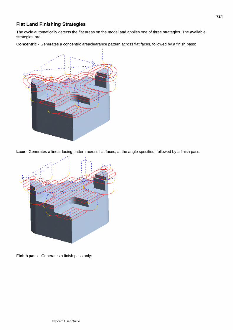
Flat Land Finishing Strategies
The cycle automatically detects the flat areas on the model and applies one of three strategies. The availablestrategies are:
Concentric - Generates a concentric areaclearance pattern across flat faces, followed by a finish pass:
Lace - Generates a linear lacing pattern across flat faces, at the angle specified, followed by a finish pass:
Finish pass - Generates a finish pass only:
724
Edgcam User Guide
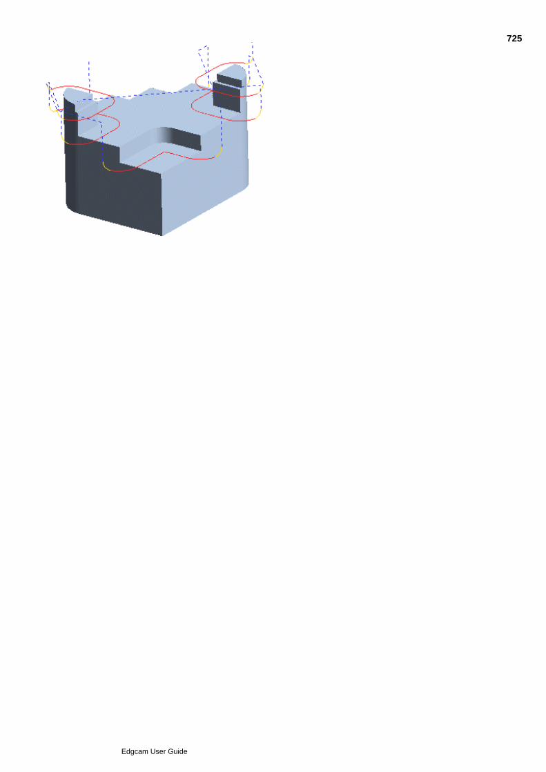
725
Edgcam User Guide

726
Edgcam User Guide

Using the Flat Land Finishing Cycle
You should have one or more surfaces ready to machine.
Select the Flat Land Finishing (Mill Cycles menu) command.1.
Set the parameters for the cycle and click OK.2.
Select the surfaces you want to machine and perform a Finish.3.
Digitise containment boundaries if required and perform a Finish.4.
Edgecam now produces the toolpath.
Note on using Flat Land Finishing with corner radius tools
727
Edgcam User Guide

Rest Machining in the Flat Land Finishing Cycle
"Rest machining" allows you to machine rest material areas that have been left by a larger tool in a previousmachining cycle (not limited to Flat Land Finishing, previous cycle may have been Roughing or Parallel Lacefor example).
Use the following three modifiers to define the rest material area:
Previous Tool Diameter - Specifies a tool diameter value for the tool that will define the rest machining area.
Previous Corner Radius - Specifies a corner radius value for the tool that will define the rest machining area.
Previous Stand Off - (Only available when previous cycle was Flat Land Finishing cycle) Specifies a stand offdistance value that will define the rest machining area. The Stand Off Distance is specified on the General tabof the cycle.
728
Edgcam User Guide
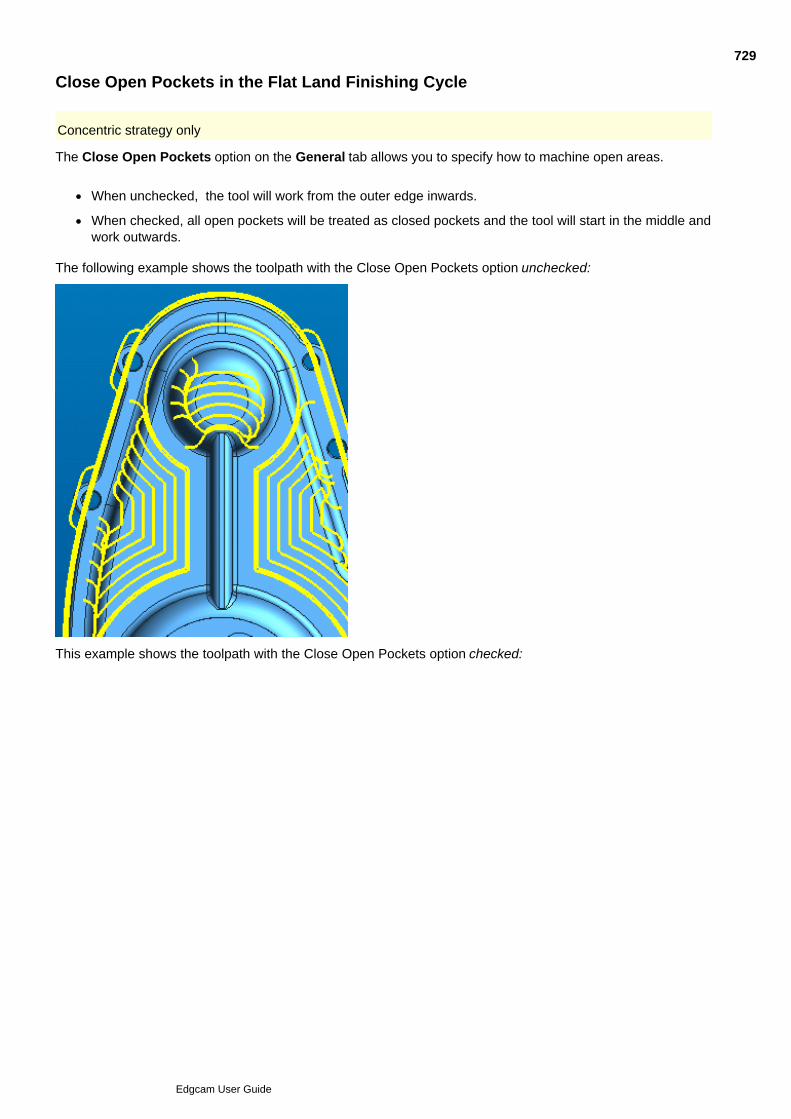
Close Open Pockets in the Flat Land Finishing Cycle
Concentric strategy only
The Close Open Pockets option on the General tab allows you to specify how to machine open areas.
When unchecked, the tool will work from the outer edge inwards.
When checked, all open pockets will be treated as closed pockets and the tool will start in the middle andwork outwards.
The following example shows the toolpath with the Close Open Pockets option unchecked:
This example shows the toolpath with the Close Open Pockets option checked:
729
Edgcam User Guide
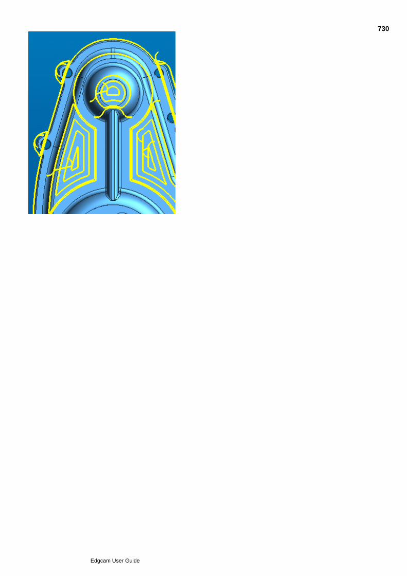
730
Edgcam User Guide
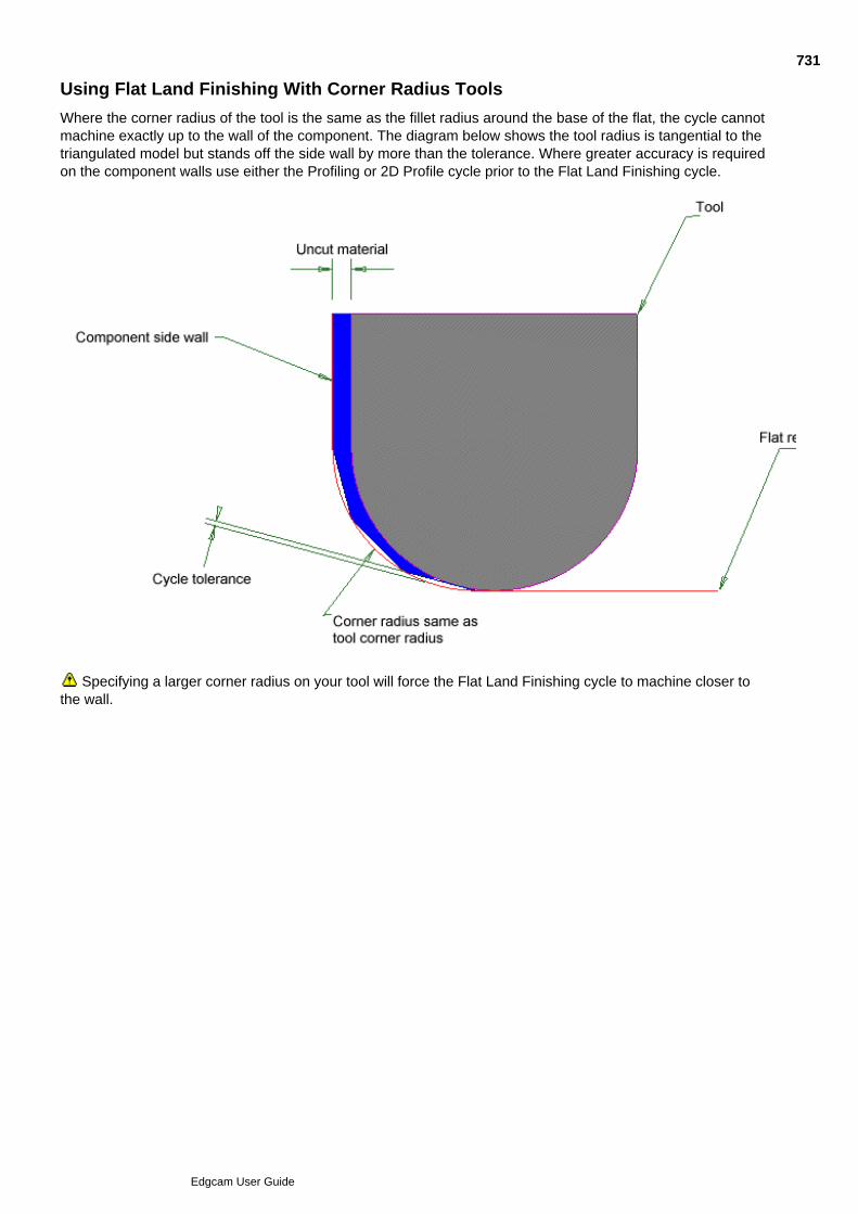
Using Flat Land Finishing With Corner Radius Tools
Where the corner radius of the tool is the same as the fillet radius around the base of the flat, the cycle cannotmachine exactly up to the wall of the component. The diagram below shows the tool radius is tangential to thetriangulated model but stands off the side wall by more than the tolerance. Where greater accuracy is requiredon the component walls use either the Profiling or 2D Profile cycle prior to the Flat Land Finishing cycle.
Specifying a larger corner radius on your tool will force the Flat Land Finishing cycle to machine closer tothe wall.
731
Edgcam User Guide

Surface Milling
Edgecam’s surface milling module can simultaneously control the XYZ linear axes of the machine tool.
Exact mathematical definitions are used to store and display Edgecam surfaces. The accuracy of a surfacemilling toolpath therefore depends entirely on the value you specify for the Tolerance parameter for that cycle.
Also see Notes on Surface Creation.
Operations menu commands
Cycles menu commands
See Also
Roughing Cycle
Parallel Lace Cycle
Profiling Cycle
Constant Cusp Finishing
Rest Finishing Cycle
Flat Land Finishing
Projection Cycles
Pencil Mill Cycle
Feeding the Tool Over Parametric Surfaces
732
Edgcam User Guide

Parallel Lace Cycle
Use the Parallel Lace (Mill Cycles menu) command when milling several surfaces at the same time.
Parallel Lace includes in-built gouge protection, which makes it the ideal cycle to machine multiple surfaceswith.
You can use this cycle for roughing (by specifying values for the Level, Cut Increment and Safe Distanceparameters), semi-roughing or finishing the surface.
The Parallel Lace cycle applies lead moves to all levels when a Cut Increment has been specified.
You can also use a bounding entity to limit the cycle to a portion of the selected surface(s).
This cycle works best with flat or gently curved parts. When machining parts with significant bulges anddepressions, consider using the Profiling cycle instead.
The Control tab offers a number of modifiers that can be used to optimise the Parallel Lace toolpath
You can choose whether to automatically maintain 'Up Mill' or 'Down Mill' cutting whatever the angle ofthe surface. See Choosing Up or Down Mill in the Parallel Lace Cycle.
You can restrict the toolpath generated by the cycle by specifying minimum and maximum contactangles. See Using Contact Angles.
You can specify Check Surfaces, which are surfaces that you don't want to be machined.
The Exclude Flat Areas option allows you to exclude flat areas. These can be machined separately usingthe Flat Land Finishing cycle. See Excluding Flat Areas in the Parallel Lace Cycle.
Use the Perpendicular Lace option to re-machine steeper areas. See Using the Perpendicular LaceOption.
Improve the lead in/out conditions by removing any rollovers on the external edge of the part. SeeIgnoring External Edges.
The tool normally rolls around any external corner and maintains contact. In some cases this causes thecorner to be eroded, so Edgecam offers several corner control strategies. See Corner Strategies in theParallel Lace Cycle.
You can 'clip to depth'.
You can contain the toolpath within boundary geometry.
To use the Parallel Lace cycle
You should have one or more surfaces ready to machine.
Select the Parallel Lace command.1.
Set the parameters for the cycle and click OK.2.
Select the surfaces you want to mill and then perform a Finish.3.
Digitise any boundary entities to limit the extent of the cycle and then perform a Finish.4.
The system now produces the toolpath.
Also See
733
Edgcam User Guide

Intelligent Lead and Link Moves734
Edgcam User Guide
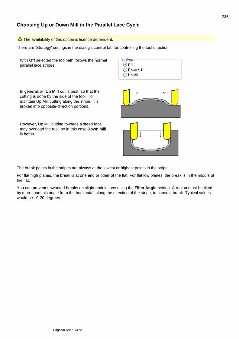
Choosing Up or Down Mill in the Parallel Lace Cycle
The availability of this option is licence dependent.
There are 'Strategy' settings in the dialog's control tab for controlling the tool direction.
With Off selected the toolpath follows the normalparallel lace stripes.
In general, an Up Mill cut is best, so that thecutting is done by the side of the tool. Tomaintain Up Mill cutting along the stripe, it isbroken into opposite-direction portions.
However, Up Mill cutting towards a steep facemay overload the tool, so in this case Down Millis better.
The break points in the stripes are always at the lowest or highest points in the stripe.
For flat high planes, the break is at one end or other of the flat. For flat low planes, the break is in the middle ofthe flat.
You can prevent unwanted breaks on slight undulations using the Filter Angle setting. A region must be tiltedby more than this angle from the horizontal, along the direction of the stripe, to cause a break. Typical valueswould be 10-20 degrees.
735
Edgcam User Guide
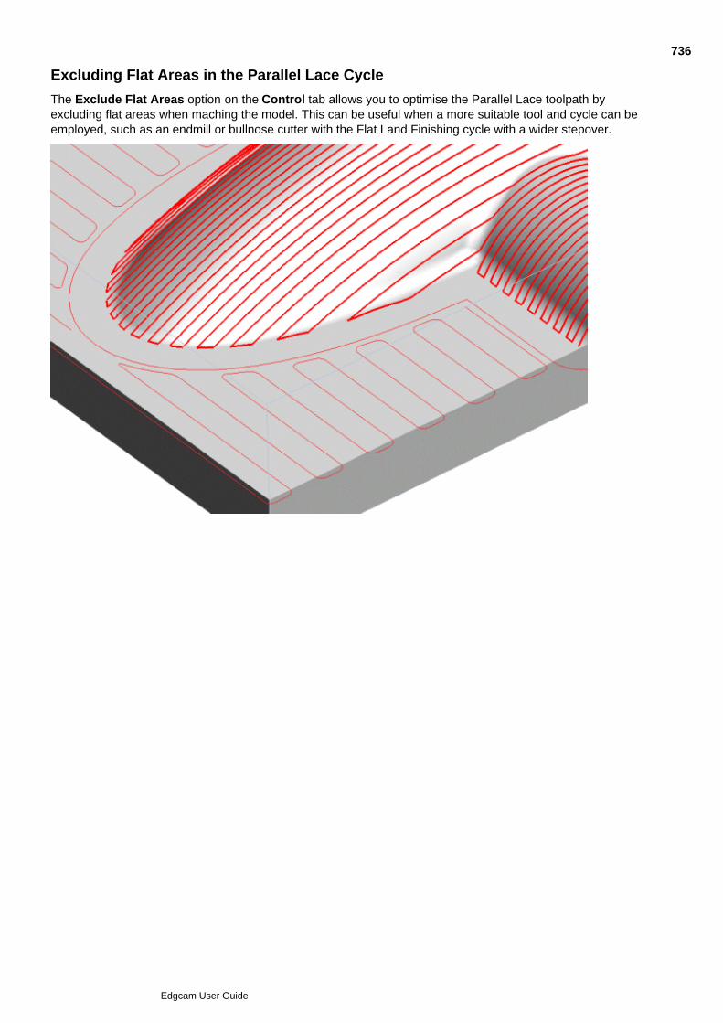
Excluding Flat Areas in the Parallel Lace Cycle
The Exclude Flat Areas option on the Control tab allows you to optimise the Parallel Lace toolpath byexcluding flat areas when maching the model. This can be useful when a more suitable tool and cycle can beemployed, such as an endmill or bullnose cutter with the Flat Land Finishing cycle with a wider stepover.
736
Edgcam User Guide
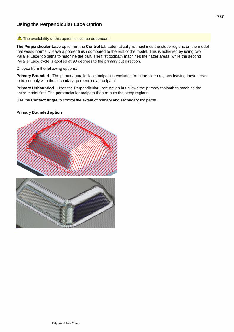
Using the Perpendicular Lace Option
The availability of this option is licence dependant.
The Perpendicular Lace option on the Control tab automatically re-machines the steep regions on the modelthat would normally leave a poorer finish compared to the rest of the model. This is achieved by using twoParallel Lace toolpaths to machine the part. The first toolpath machines the flatter areas, while the secondParallel Lace cycle is applied at 90 degrees to the primary cut direction.
Choose from the following options:
Primary Bounded - The primary parallel lace toolpath is excluded from the steep regions leaving these areasto be cut only with the secondary, perpendicular toolpath.
Primary Unbounded - Uses the Perpendicular Lace option but allows the primary toolpath to machine theentire model first. The perpendicular toolpath then re-cuts the steep regions.
Use the Contact Angle to control the extent of primary and secondary toolpaths.
Primary Bounded option
737
Edgcam User Guide
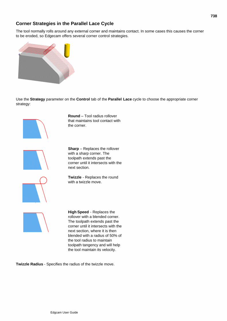
Corner Strategies in the Parallel Lace Cycle
The tool normally rolls around any external corner and maintains contact. In some cases this causes the cornerto be eroded, so Edgecam offers several corner control strategies.
Use the Strategy parameter on the Control tab of the Parallel Lace cycle to choose the appropriate cornerstrategy:
Round – Tool radius rolloverthat maintains tool contact withthe corner.
Sharp – Replaces the rolloverwith a sharp corner. Thetoolpath extends past thecorner until it intersects with thenext section.
Twizzle - Replaces the roundwith a twizzle move.
High Speed - Replaces therollover with a blended corner.The toolpath extends past thecorner until it intersects with thenext section, where it is thenblended with a radius of 50% ofthe tool radius to maintaintoolpath tangency and will helpthe tool maintain its velocity.
Twizzle Radius - Specifies the radius of the twizzle move.
738
Edgcam User Guide
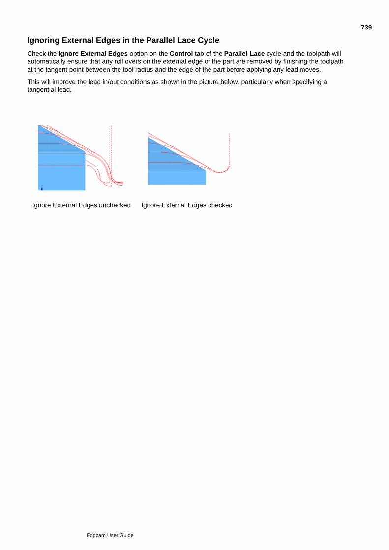
Ignoring External Edges in the Parallel Lace Cycle
Check the Ignore External Edges option on the Control tab of the Parallel Lace cycle and the toolpath willautomatically ensure that any roll overs on the external edge of the part are removed by finishing the toolpathat the tangent point between the tool radius and the edge of the part before applying any lead moves.
This will improve the lead in/out conditions as shown in the picture below, particularly when specifying atangential lead.
Ignore External Edges unchecked Ignore External Edges checked
739
Edgcam User Guide

Parallel Lace Dialog Depth tab
Here are details on the settings in the Parallel Lace dialog, Depth tab (you can also access this help by clickingthe Help button in the dialog):
740
Edgcam User Guide

741
Edgcam User Guide

Constant Cusp Finishing
Use the Constant Cusp Finishing (Mill Cycles menu) command to generate a 3D toolpath thatmaintains a constant surface stepover from one pass to the next.
The Constant Cusp Finishing cycle produces a toolpath that can be defined from a drive curve or boundary.
To use the Constant Cusp Finishing cycle
You should have one or more surfaces ready to machine.
Select the Constant Cusp Finishing command.1.
Set the parameters for the cycle and click OK.2.
Select the surfaces you want to machine and perform a Finish.3.
Digitise containment boundaries if required and perform a Finish.4.
Digitise a single drive curve, if required (see Using Drive Curves in Constant Cusp Finishing) and performa Finish. If you don't specify a drive curve, the toolpath is based on collapsing the containmentboundaries. If neither drive curve nor containment boundaries are specified, the toolpath is based oncollapsing the surface boundaries.
5.
Edgecam now produces the toolpath.
See Also
Intelligent Lead and Link Moves
Using Contact Angles
Clipping to Depth
742
Edgcam User Guide

743
Edgcam User Guide
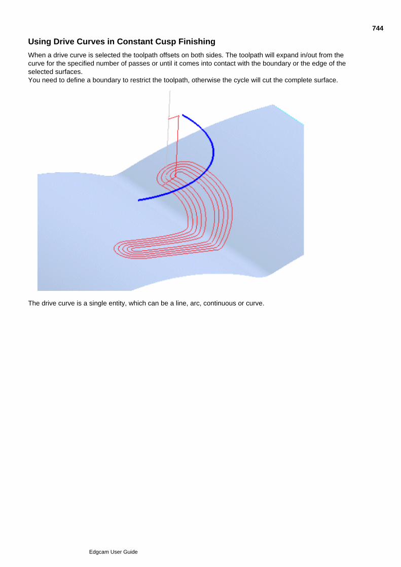
Using Drive Curves in Constant Cusp Finishing
When a drive curve is selected the toolpath offsets on both sides. The toolpath will expand in/out from thecurve for the specified number of passes or until it comes into contact with the boundary or the edge of theselected surfaces.You need to define a boundary to restrict the toolpath, otherwise the cycle will cut the complete surface.
The drive curve is a single entity, which can be a line, arc, continuous or curve.
744
Edgcam User Guide

Constant Cusp Finishing dialog - Depth tab
Here are details on the settings in the Constant Cusp Finishing dialog, Depth tab (you can also access this helpby clicking the Help button in the dialog):
745
Edgcam User Guide

Rest Finishing Cycle
Use Mill Cycles menu Rest Finishing Cycle to remove leftover material.
Here are details on using the cycle, and on the cycle's settings (you can also access this help by clicking theHelp button in the dialog):
746
Edgcam User Guide

747
Edgcam User Guide

Projection Cycles
Edgecam provides a series of cycles for surface machining, based on projecting existing or new 2D cycles ontosurfaces.
Depending on your licence, these cycles are available:
Project Toolpath – Finishing cycleproduced by projecting an existing Planar cycleonto one or more surfaces.
Project Boundary Collapse – Finishingcycle produced by projecting an Areaclearancecycle onto one or more surfaces*.
Project Flow Curves – Finishing cycleproduced by projecting a Lace cycle based ontwo curves onto one or more surfaces*.
Project Circular Pattern – Finishing cyclefor round bosses or pockets, with three patternstrategies (Radial, Concentric and Spiral)*.
These toolpaths are all fully gouge-protected.
With all projection toolpath cycles, the toolpath can be clipped to selected containment boundaries. You canselect more than one boundary, and boundaries may lie inside another so as to define a region. However, oneboundary may not overlap another, and a single boundary may not intersect itself.
See Also
Project Toolpath Cycle
Project Boundary Collapse Cycle
Project Flow Curves Cycle
Project Circular Pattern Cycle
Cut Across and Step Angle
Toolpath Off Surface for Projection Cycles
Intelligent Lead and Link Moves
748
Edgcam User Guide

Project Toolpath Cycle
The Project Toolpath cycle finishes surfaces by projecting the toolpath from an existing cycle onto them.
The existing cycle:
Must be an Areaclear, Lace, Profile, Slot, Facemill, Text, Roughing or Profiling.
Must have a single pass toolpath; that is it cannot have a Cut Increment set. This would lead tounpredictable results.
Must have its Model Type option set to Wireframe (applies only to Roughing and Profiling cycles).
With the toolpath defined by the existing cycle, the Project cycle defines the approach strategy and the depthparameters.
To use Project Toolpath
Make sure that the last instruction in the current sequence is a cycle that conforms to the aboveconditions (you will probably specially create this cycle, using a profile related to your surface).
1.
Select the Project Toolpath cycle.2.
Specify the parameters for the cycle and click OK.3.
Digitise the surfaces for projection and then perform a Finish.4.
The toolpath is now generated.
See Also
Intelligent Lead and Link Moves
Clipping To Depth
749
Edgcam User Guide
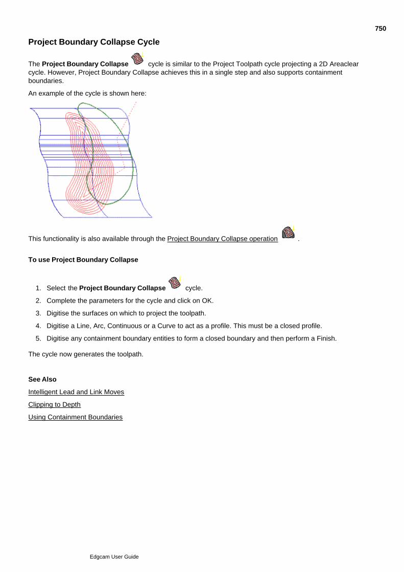
Project Boundary Collapse Cycle
The Project Boundary Collapse cycle is similar to the Project Toolpath cycle projecting a 2D Areaclearcycle. However, Project Boundary Collapse achieves this in a single step and also supports containmentboundaries.
An example of the cycle is shown here:
This functionality is also available through the Project Boundary Collapse operation .
To use Project Boundary Collapse
Select the Project Boundary Collapse cycle.1.
Complete the parameters for the cycle and click on OK.2.
Digitise the surfaces on which to project the toolpath.3.
Digitise a Line, Arc, Continuous or a Curve to act as a profile. This must be a closed profile.4.
Digitise any containment boundary entities to form a closed boundary and then perform a Finish.5.
The cycle now generates the toolpath.
See Also
Intelligent Lead and Link Moves
Clipping to Depth
Using Containment Boundaries
750
Edgcam User Guide
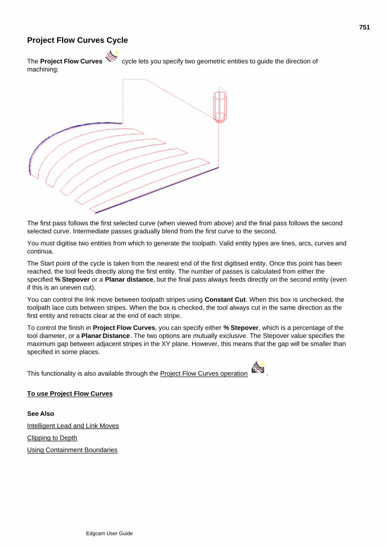
Project Flow Curves Cycle
The Project Flow Curves cycle lets you specify two geometric entities to guide the direction ofmachining:
The first pass follows the first selected curve (when viewed from above) and the final pass follows the secondselected curve. Intermediate passes gradually blend from the first curve to the second.
You must digitise two entities from which to generate the toolpath. Valid entity types are lines, arcs, curves andcontinua.
The Start point of the cycle is taken from the nearest end of the first digitised entity. Once this point has beenreached, the tool feeds directly along the first entity. The number of passes is calculated from either thespecified % Stepover or a Planar distance, but the final pass always feeds directly on the second entity (evenif this is an uneven cut).
You can control the link move between toolpath stripes using Constant Cut. When this box is unchecked, thetoolpath lace cuts between stripes. When the box is checked, the tool always cut in the same direction as thefirst entity and retracts clear at the end of each stripe.
To control the finish in Project Flow Curves, you can specify either % Stepover, which is a percentage of thetool diameter, or a Planar Distance. The two options are mutually exclusive. The Stepover value specifies themaximum gap between adjacent stripes in the XY plane. However, this means that the gap will be smaller thanspecified in some places.
This functionality is also available through the Project Flow Curves operation .
To use Project Flow Curves
See Also
Intelligent Lead and Link Moves
Clipping to Depth
Using Containment Boundaries
751
Edgcam User Guide
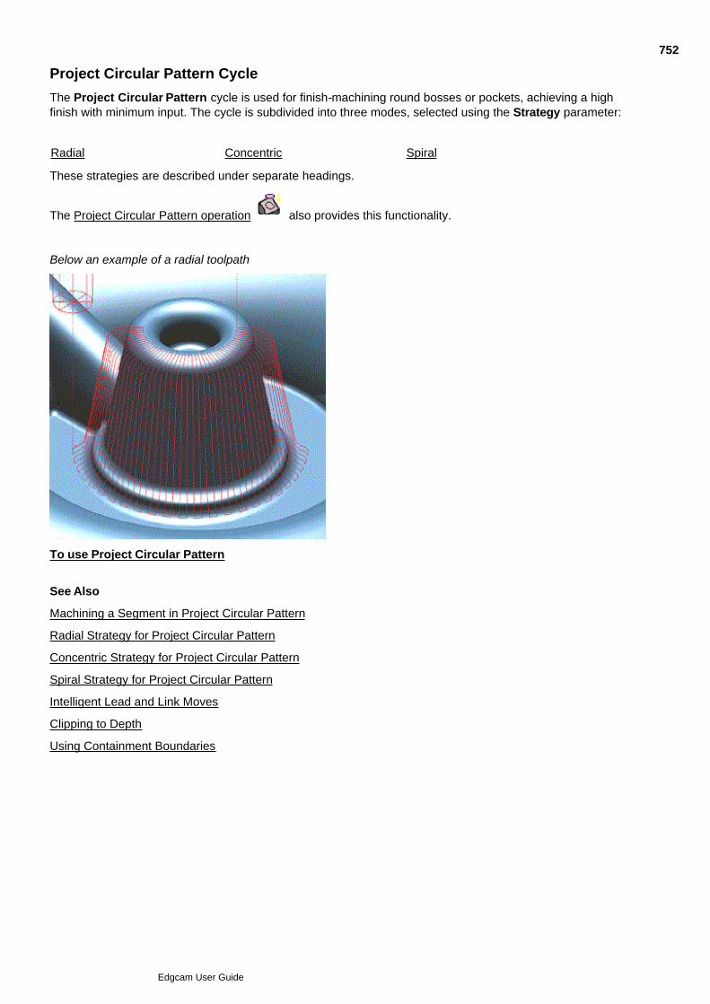
Project Circular Pattern Cycle
The Project Circular Pattern cycle is used for finish-machining round bosses or pockets, achieving a highfinish with minimum input. The cycle is subdivided into three modes, selected using the Strategy parameter:
Radial Concentric Spiral
These strategies are described under separate headings.
The Project Circular Pattern operation also provides this functionality.
Below an example of a radial toolpath
To use Project Circular Pattern
See Also
Machining a Segment in Project Circular Pattern
Radial Strategy for Project Circular Pattern
Concentric Strategy for Project Circular Pattern
Spiral Strategy for Project Circular Pattern
Intelligent Lead and Link Moves
Clipping to Depth
Using Containment Boundaries
752
Edgcam User Guide

To use Project Circular Pattern
To use Project Circular Pattern
Select the Project Circular Pattern cycle.1.
Complete the parameters for the cycle and click OK.2.
Digitise the surfaces to be projected onto and then perform a Finish.3.
Digitise the outer arc.4.
Optionally digitise an entity to set the inner radius value.5.
Digitise the containment boundaries to form a closed boundary and then perform a Finish.6.
The cycle now generates the toolpath.
753
Edgcam User Guide

Machining a Segment in Project Circular Pattern
The toolpath always starts at 0 degrees (3 o’clock) and machines a complete circle, unless modified by theStart Angle and End Angle.
You can specify a Start Angle and End Angle to limit the cycle to a segment of the circle. The start and endangles are entered in the same fashion as creating a geometric arc, in that the segment is always anti-clockwise from the start angle to the end angle. When the Direction is specified as clockwise the toolpathstarts at the end angle, and when the Direction is counterclockwise the toolpath begins at the start angle.
When only a start angle is entered, the cycle machines a complete circle, starting at the specified value.
754
Edgcam User Guide

Radial Strategy for Project Circular Pattern
Selecting the Radial strategy for the Project Circular cycleproduces the type of toolpath shown here.
You can control the finish by specifying either a PlanarDistance, or a Stepover representing the distance at theouter edge between adjacent cuts, or the Step Angle betweencuts. The three options are mutually exclusive.
When the Constant Cut box is unchecked, the tool laces up and down the radial lines and links the ends byfollowing the inner or outer arc, thus producing a continuous path to project.
When Constant Cut is checked, the radial lines are cut in a constant direction (which depends on the Startparameter). Finally, the Direction determines which way to go around the feature.
755
Edgcam User Guide

Concentric Strategy for Project Circular Pattern
Selecting the Concentric strategy for the Project Circularcycle produces the type of toolpath shown here.
To control the finish, specify either a Planar Distance or aStepover representing the distance between adjacentcuts.
When the Constant Cut box is checked, the tool cuts each concentric arc in the same direction, performing aretract move between each cut.
When Constant Cut is unchecked, the tool lace cuts between concentric arcs and ignores the Directionmodifier.
756
Edgcam User Guide

Spiral Strategy for Project Circular Pattern
Selecting the Spiral strategy for the Project Circular cycleproduces the type of toolpath shown here.
To control the finish, you can specify either a PlanarDistance, or a Stepover that represents the distancebetween adjacent cuts. The two options are mutuallyexclusive.
The toolpath starts at either the inner or outer arc (dependent on Start) at the nominated Start Angle. TheAngle defaults to 0 degrees (3 o’clock). Once positioned on the surface using the standard approach method,the cycle will commence. The Direction will force the tool to cut CLW or CCLW.
The cycle performs a finish pass on the inner arc (if given) and the outer arc. The tool will cut completelyaround the start circle, then cut the spiral, then cut the finish circle.
757
Edgcam User Guide

Project Circular Pattern dialog - Depth tab
Here are details on the settings in the Project Circular Pattern dialog, Depth tab (you can also access this helpby clicking the Help button in the dialog):
758
Edgcam User Guide

759
Edgcam User Guide
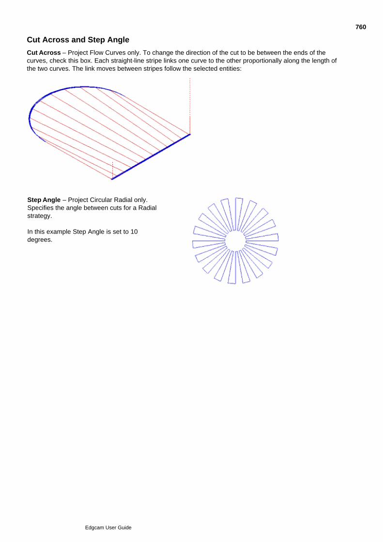
Cut Across and Step Angle
Cut Across – Project Flow Curves only. To change the direction of the cut to be between the ends of thecurves, check this box. Each straight-line stripe links one curve to the other proportionally along the length ofthe two curves. The link moves between stripes follow the selected entities:
Step Angle – Project Circular Radial only.Specifies the angle between cuts for a Radialstrategy.
In this example Step Angle is set to 10degrees.
760
Edgcam User Guide
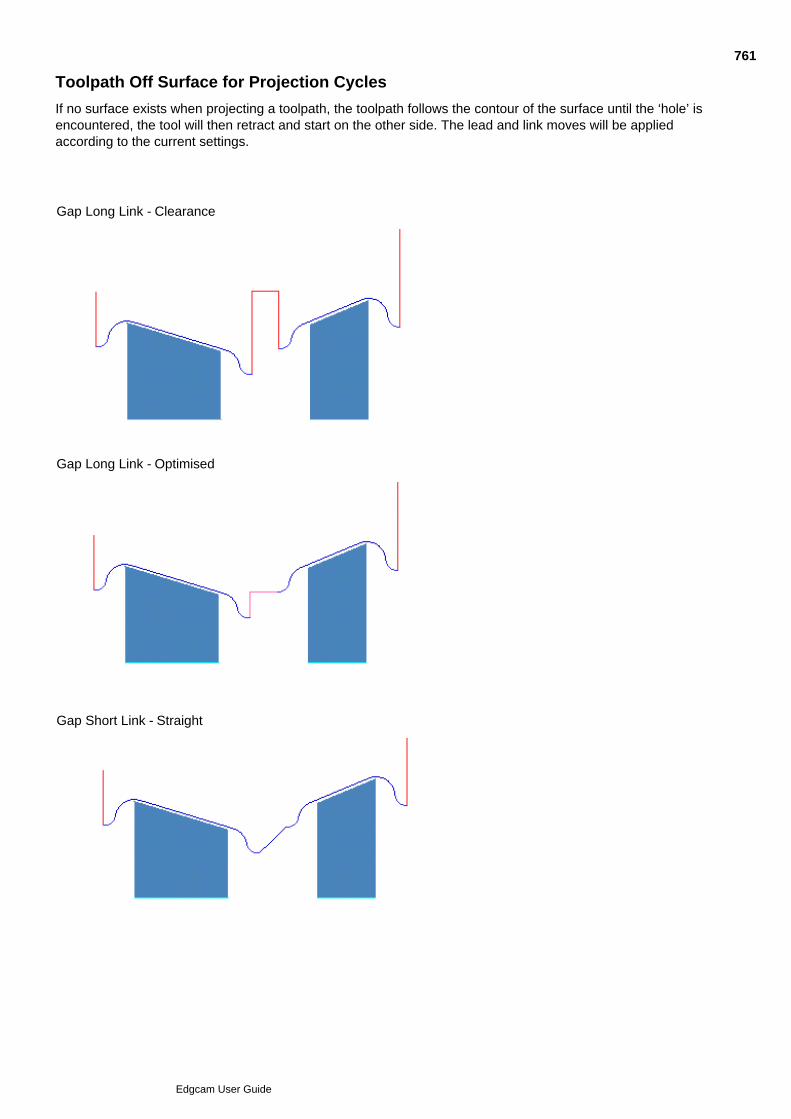
Toolpath Off Surface for Projection Cycles
If no surface exists when projecting a toolpath, the toolpath follows the contour of the surface until the ‘hole’ isencountered, the tool will then retract and start on the other side. The lead and link moves will be appliedaccording to the current settings.
Gap Long Link - Clearance
Gap Long Link - Optimised
Gap Short Link - Straight
761
Edgcam User Guide
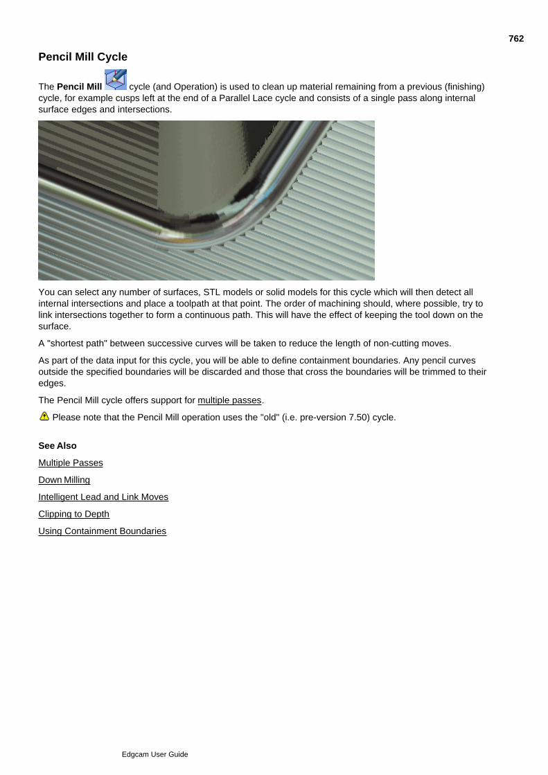
Pencil Mill Cycle
The Pencil Mill cycle (and Operation) is used to clean up material remaining from a previous (finishing)cycle, for example cusps left at the end of a Parallel Lace cycle and consists of a single pass along internalsurface edges and intersections.
You can select any number of surfaces, STL models or solid models for this cycle which will then detect allinternal intersections and place a toolpath at that point. The order of machining should, where possible, try tolink intersections together to form a continuous path. This will have the effect of keeping the tool down on thesurface.
A "shortest path" between successive curves will be taken to reduce the length of non-cutting moves.
As part of the data input for this cycle, you will be able to define containment boundaries. Any pencil curvesoutside the specified boundaries will be discarded and those that cross the boundaries will be trimmed to theiredges.
The Pencil Mill cycle offers support for multiple passes.
Please note that the Pencil Mill operation uses the "old" (i.e. pre-version 7.50) cycle.
See Also
Multiple Passes
Down Milling
Intelligent Lead and Link Moves
Clipping to Depth
Using Containment Boundaries
762
Edgcam User Guide
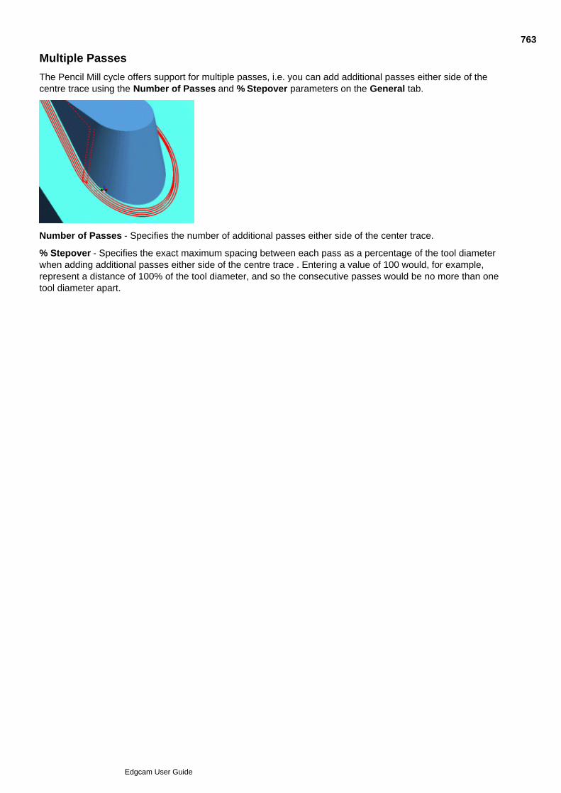
Multiple Passes
The Pencil Mill cycle offers support for multiple passes, i.e. you can add additional passes either side of thecentre trace using the Number of Passes and % Stepover parameters on the General tab.
Number of Passes - Specifies the number of additional passes either side of the center trace.
% Stepover - Specifies the exact maximum spacing between each pass as a percentage of the tool diameterwhen adding additional passes either side of the centre trace . Entering a value of 100 would, for example,represent a distance of 100% of the tool diameter, and so the consecutive passes would be no more than onetool diameter apart.
763
Edgcam User Guide
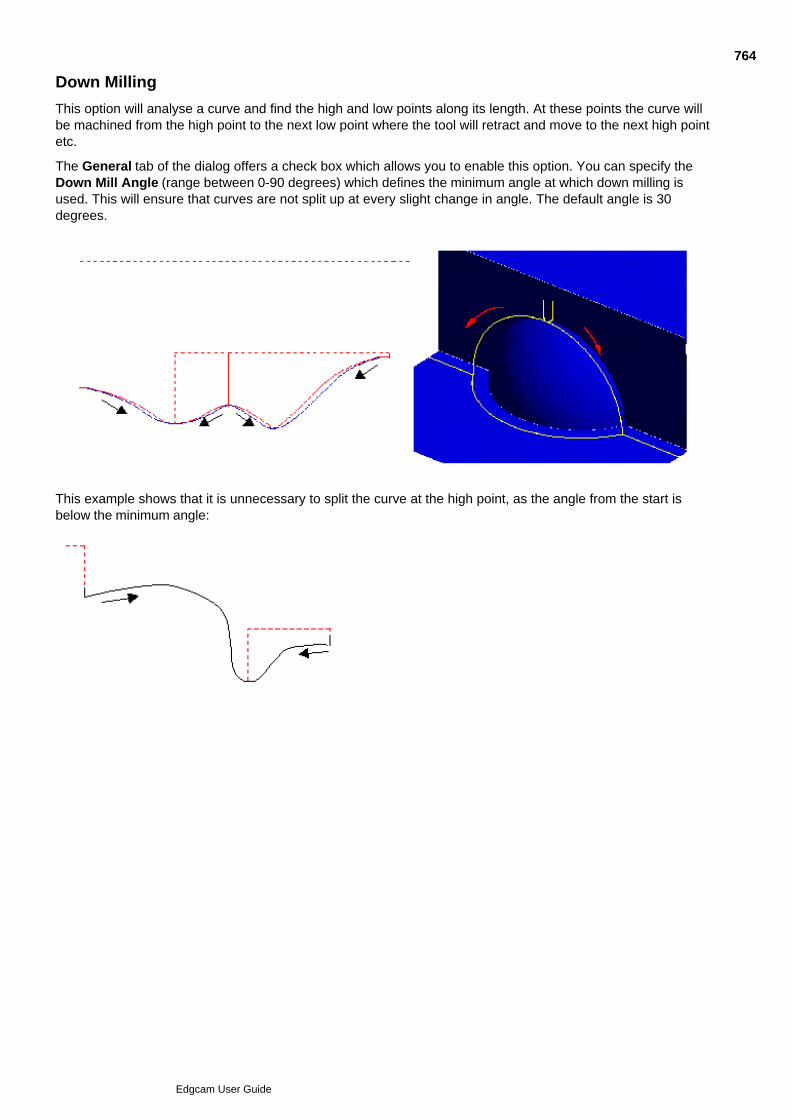
Down Milling
This option will analyse a curve and find the high and low points along its length. At these points the curve willbe machined from the high point to the next low point where the tool will retract and move to the next high pointetc.
The General tab of the dialog offers a check box which allows you to enable this option. You can specify theDown Mill Angle (range between 0-90 degrees) which defines the minimum angle at which down milling isused. This will ensure that curves are not split up at every slight change in angle. The default angle is 30degrees.
This example shows that it is unnecessary to split the curve at the high point, as the angle from the start isbelow the minimum angle:
764
Edgcam User Guide

Pencil Mill dialog - Depth tab
Here are details on the settings in the Pencil Mill dialog, Depth tab (you can also access this help by clickingthe Help button in the dialog):
765
Edgcam User Guide

766
Edgcam User Guide
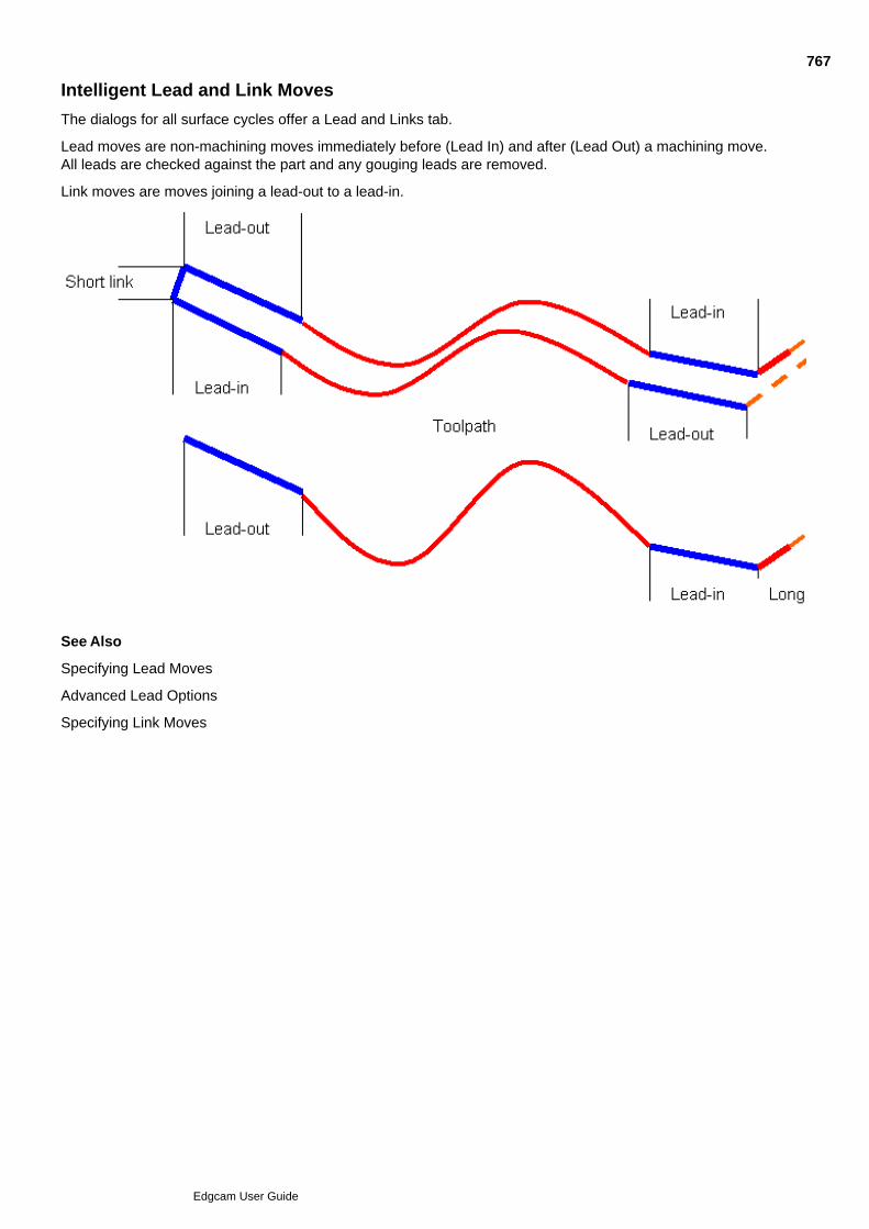
Intelligent Lead and Link Moves
The dialogs for all surface cycles offer a Lead and Links tab.
Lead moves are non-machining moves immediately before (Lead In) and after (Lead Out) a machining move.All leads are checked against the part and any gouging leads are removed.
Link moves are moves joining a lead-out to a lead-in.
See Also
Specifying Lead Moves
Advanced Lead Options
Specifying Link Moves
767
Edgcam User Guide

Specifying Lead Moves
A lead move consists of either an arc or line joining onto or off a machining segment. The arc is specified bythe Angle and Radius parameters and the linear segment by a 3D Length.
You can choose between the following orientations:
None – No lead move applied, just safe distance.
Horizontal* – Horizontal lead in a horizontal plane
Tangential – In a vertical plane, leading tangentially off the toolpath.
Vertical – In a vertical plane, joining at a horizontal tangent.
Normal – Normal to the surface.
*When the lead type is set to Horizontal the lead in/out angle can be set to a maximum of 180 degrees. For allother types a maximum of 90 degrees is allowed.
NOTE: If you have specified a depth and do not want the lead move to go below this level use vertical orhorizontal only.
The Feedrate for lead moves is specified as a percentage of the feedrate on the General tab.
Check Apply To Long Link Only to only apply lead moves where they join long link moves. These lead moveswill only be applied at the beginning (lead in) or end (lead out) of a region.
If Length, Angle and Radius are set to 0 or unspecified there will be a lead of zero length, i.e. no lead move.
The cycles ensure that the tool feeds from the Safe Distance. If the start of the lead move is not the SafeDistance off the model then a feed move will be inserted.
Also see
Advanced Lead Options
768
Edgcam User Guide

Advanced Lead Options
The Lead tab of the Profiling, Pencil Mill and Flat Land Finishing cycles offers a number of advancedoptions.
Apply Safe Distance to Horizontal Lead Moves
Overlap Distance for Closed Profiles
Profile Extensions
Automatic Start Point
Instead of trimming a lead move back because of gouge protection, the start point will automatically movealong the toolpath until the lead move can be fitted the safe distance away from the gouge point.
In the event that a suitable position cannot be found the original start point will be used and the lead will betrimmed away as before.
769
Edgcam User Guide
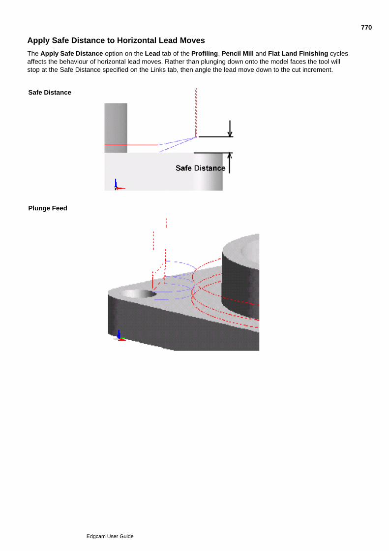
Apply Safe Distance to Horizontal Lead Moves
The Apply Safe Distance option on the Lead tab of the Profiling, Pencil Mill and Flat Land Finishing cyclesaffects the behaviour of horizontal lead moves. Rather than plunging down onto the model faces the tool willstop at the Safe Distance specified on the Links tab, then angle the lead move down to the cut increment.
Safe Distance
Plunge Feed
Apply Safe Distance
770
Edgcam User Guide
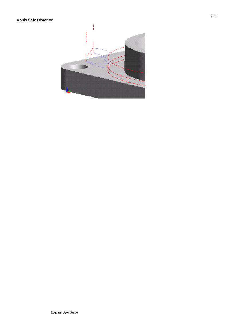
Apply Safe Distance771
Edgcam User Guide
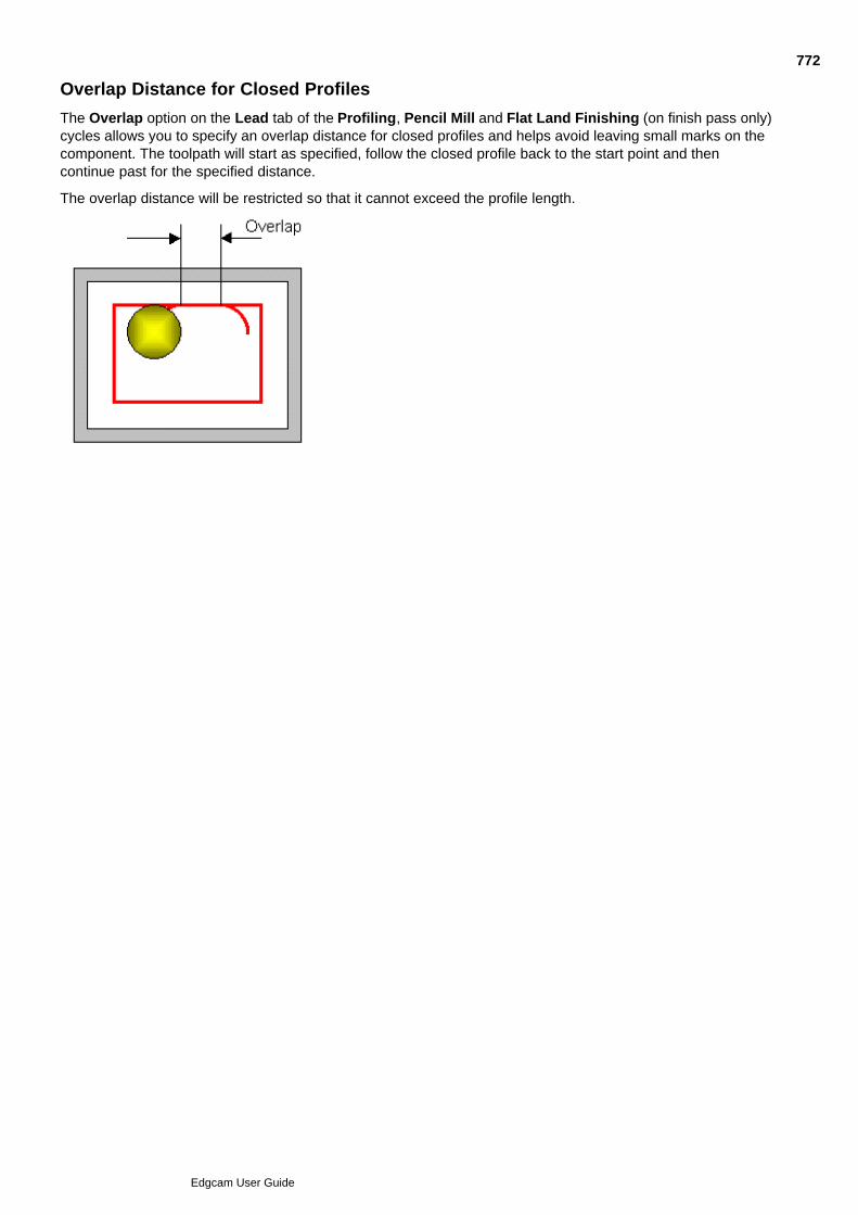
Overlap Distance for Closed Profiles
The Overlap option on the Lead tab of the Profiling, Pencil Mill and Flat Land Finishing (on finish pass only)cycles allows you to specify an overlap distance for closed profiles and helps avoid leaving small marks on thecomponent. The toolpath will start as specified, follow the closed profile back to the start point and thencontinue past for the specified distance.
The overlap distance will be restricted so that it cannot exceed the profile length.
772
Edgcam User Guide
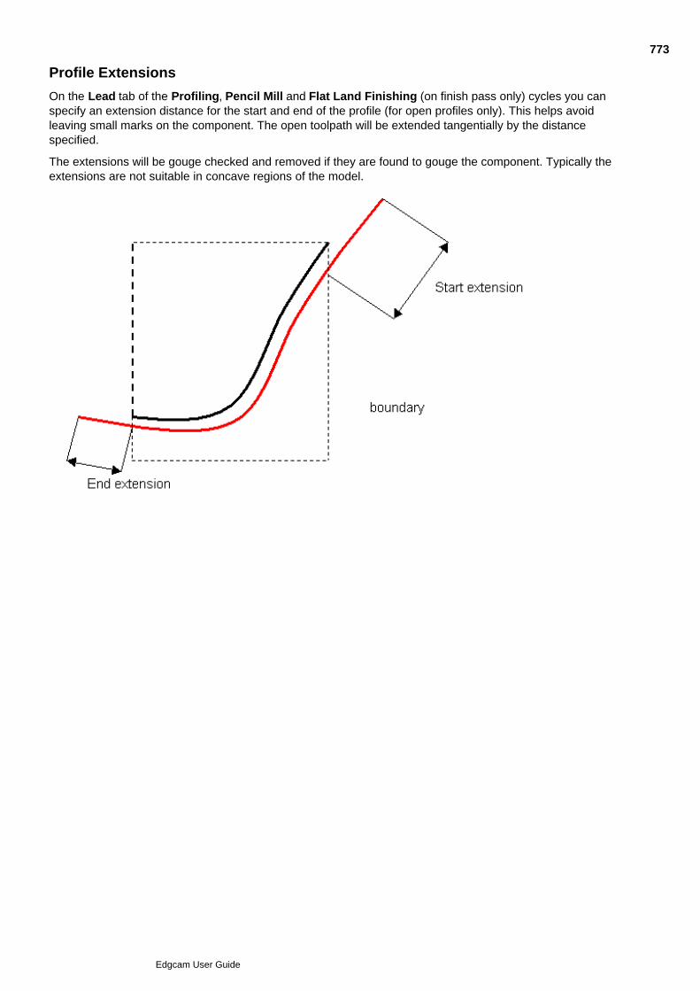
Profile Extensions
On the Lead tab of the Profiling, Pencil Mill and Flat Land Finishing (on finish pass only) cycles you canspecify an extension distance for the start and end of the profile (for open profiles only). This helps avoidleaving small marks on the component. The open toolpath will be extended tangentially by the distancespecified.
The extensions will be gouge checked and removed if they are found to gouge the component. Typically theextensions are not suitable in concave regions of the model.
773
Edgcam User Guide
Specifying Link Moves
Link moves are moves joining a Lead Out and a Lead In. All links are checked against the part and adjusted toprevent gouging.
A distinction between Short and Long link moves is made.
Short Link = Feed Move
Long Link = Rapid or High Feedrate Move
Short links are links where the 3D distance between the end point of the previous machining segmentand the start point of the following machining segment is less than the Short Link Distance.
If you specify a Short Link Distance of 0 only one type of link will be generated, namely Long Links.
Short Links can be one of three types:
Smooth – An arc-like smooth transition between ends.
Straight – A straight linear connection.
Step – A connection consisting of two straight lines. Either a move in XY is followed by a move down in Z OR amove up in Z is followed by a move in XY.
Long Links can be one of two types:
Optimised – The tool moves up in Z to the highest point on the part (offset by the Safe Distance) along thejoining move, followed by a straight horizontal move and a move down to the start of the Lead In or SafeDistance (whichever is higher). The tool then moves down any remaining distance at the Plunge Feedrate. Allof these moves will be at the maximum feedrate specified in the postprocessor.
Please note that all pre-version 5.75 pencil milling cycles will use this link type by default.
Clearance – The tool makes a rapid move to the Clearance plane, followed by a rapid move in XY and a rapidmove down to the start of the Lead in or the Safe Distance (whichever is higher). The tool then moves downany remaining distance at the Plunge Feedrate.
Safe Distance – Specifies the safe distance above the part from which the tool will feed into position. The safedistance is also included when calculating the optimised retract height over the model.
Feed When Plunging – When checked, the tool will use the Feedrate when moving down in the Z axis duringthe cycle. This is a safe option when the amount of stock material is unknown. When unchecked, the tool willrapid to the safe distance above the model then feed into position.
At the start of the surface machining cycles the tool will rapid to the clearance plane first, then continue down tothe start of the lead move.
774
Edgcam User Guide
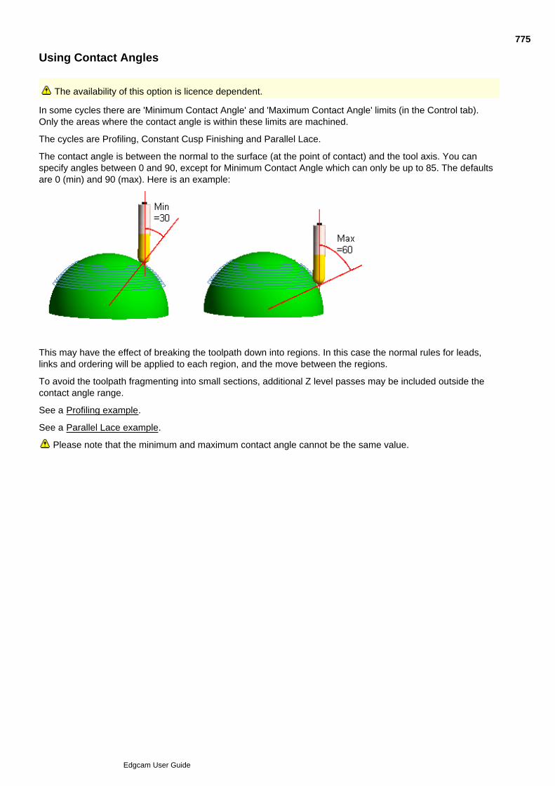
Using Contact Angles
The availability of this option is licence dependent.
In some cycles there are 'Minimum Contact Angle' and 'Maximum Contact Angle' limits (in the Control tab).Only the areas where the contact angle is within these limits are machined.
The cycles are Profiling, Constant Cusp Finishing and Parallel Lace.
The contact angle is between the normal to the surface (at the point of contact) and the tool axis. You canspecify angles between 0 and 90, except for Minimum Contact Angle which can only be up to 85. The defaultsare 0 (min) and 90 (max). Here is an example:
This may have the effect of breaking the toolpath down into regions. In this case the normal rules for leads,links and ordering will be applied to each region, and the move between the regions.
To avoid the toolpath fragmenting into small sections, additional Z level passes may be included outside thecontact angle range.
See a Profiling example.
See a Parallel Lace example.
Please note that the minimum and maximum contact angle cannot be the same value.
775
Edgcam User Guide

Batch Mode
Batch Mode can be applied to all surface cycles.
You may find that some cycles take some time to generate the appropriate toolpaths. Checking the BatchMode (Cycles menu) command lets you to bypass the toolpath generation and move on to other tasks in theworksession. At the end of the worksession, turn off Batch Mode and generate the batched toolpaths byselecting Regenerate.
776
Edgcam User Guide

Setting Preferences
Use Options menu Preferences to set preferences such as the units for the part and thetolerances.
Here are details on the preferences (you can also access this help by clicking the Help button in thePreferences dialog):
777
Edgcam User Guide

Loading and Saving STL Files
Edgecam surface models can be saved as STL (stereolithography) ASCII/Binary files.
You can also open/insert STL files, however they can only be machined using surface cycles (except PencilMill).
When opening or inserting an STL file, Edgecam will automatically generate a bounding box.
You can also intellisnap the corner points of the triangles which is useful for creating boundaries and digitisingcycle depth parameters.
STL entities can be rotated, translated, mirrored and scaled using the appropriate Edit, Transformcommands. For large STL models, any transformation may take some time. Please note that scaling a partwill scale the tolerance to which the triangles represent the original model.
778
Edgcam User Guide
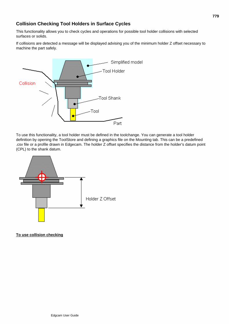
Collision Checking Tool Holders in Surface Cycles
This functionality allows you to check cycles and operations for possible tool holder collisions with selectedsurfaces or solids.
If collisions are detected a message will be displayed advising you of the minimum holder Z offset necessary tomachine the part safely.
To use this functionality, a tool holder must be defined in the toolchange. You can generate a tool holderdefinition by opening the ToolStore and defining a graphics file on the Mounting tab. This can be a predefined.csv file or a profile drawn in Edgecam. The holder Z offset specifies the distance from the holder’s datum point(CPL) to the shank datum.
To use collision checking
779
Edgcam User Guide
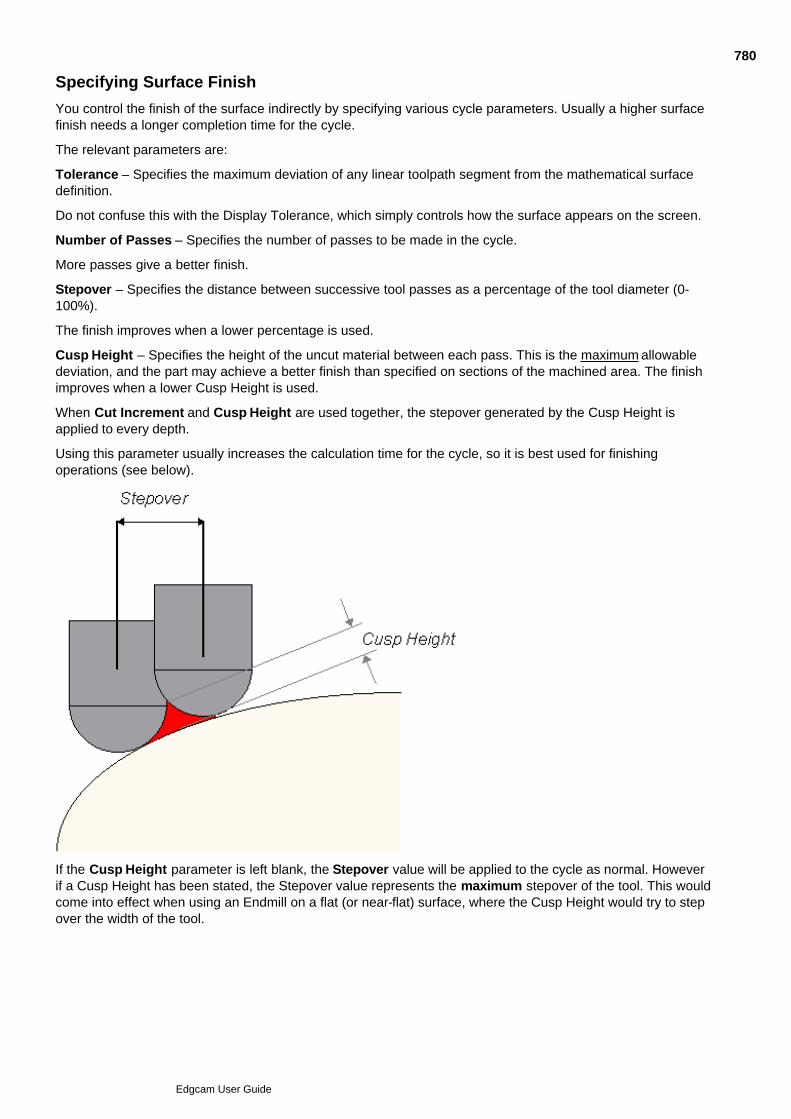
Specifying Surface Finish
You control the finish of the surface indirectly by specifying various cycle parameters. Usually a higher surfacefinish needs a longer completion time for the cycle.
The relevant parameters are:
Tolerance – Specifies the maximum deviation of any linear toolpath segment from the mathematical surfacedefinition.
Do not confuse this with the Display Tolerance, which simply controls how the surface appears on the screen.
Number of Passes – Specifies the number of passes to be made in the cycle.
More passes give a better finish.
Stepover – Specifies the distance between successive tool passes as a percentage of the tool diameter (0-100%).
The finish improves when a lower percentage is used.
Cusp Height – Specifies the height of the uncut material between each pass. This is the maximum allowabledeviation, and the part may achieve a better finish than specified on sections of the machined area. The finishimproves when a lower Cusp Height is used.
When Cut Increment and Cusp Height are used together, the stepover generated by the Cusp Height isapplied to every depth.
Using this parameter usually increases the calculation time for the cycle, so it is best used for finishingoperations (see below).
If the Cusp Height parameter is left blank, the Stepover value will be applied to the cycle as normal. Howeverif a Cusp Height has been stated, the Stepover value represents the maximum stepover of the tool. This wouldcome into effect when using an Endmill on a flat (or near-flat) surface, where the Cusp Height would try to stepover the width of the tool.
780
Edgcam User Guide

Using a Negative Offset in Surface Cycles
A negative offset cannot be equal or greater than the tool radius.
This is because to produce the negative offset, a toolpath is produced for a smaller tool, for the original non-offset geometry. Because the specified (larger) tool is used in reality, this removes more material.
For example, when machining an offset of -1.5 with a 4mm ballnose tool (2mm corner radius), a 1mm ballnosetool is effectively used for the toolpath (0.5mm corner radius).
Please note that if the effective tool size is very small, the tool could fall between small gaps in the model,increasing calculation time.
781
Edgcam User Guide

Problems when Machining Offset Surfaces
Creating surfaces from continuous entities made from many short line segments can cause problems when youlater try to machine the surface. This is because these line segments become discontinuous when Edgecamproduces an offset surface for generating toolpaths.
To avoid this problem, use the Curves, Smooth (Geometric menu) command to create single smoothedentities from the continuous entities.
782
Edgcam User Guide

Output Tolerance and Line Arc
Even if you set 'Line Arc' for 'NC Output Smoothing' in a cycle's General tab, very large radius arcs may beoutput as a line.
chord distance
If the 'chord distance' is less than the machine's Output Tolerance setting (Machine Parameters dialog, Generaltab), the arc is output as a line.
Note that as a general rule you should set the Output tolerance to the resolution of the NC controller. Mostmetric formats are 4,3 (3 decimal places), so set Output tolerance to 0.001mm. Inch format is 3,4 (4 decimalplaces), so set the output tolerance to 0.0001”. This setting is 'modal'; it defaults to the last value you set, andis remembered from one Edgecam session to the next.
783
Edgcam User Guide
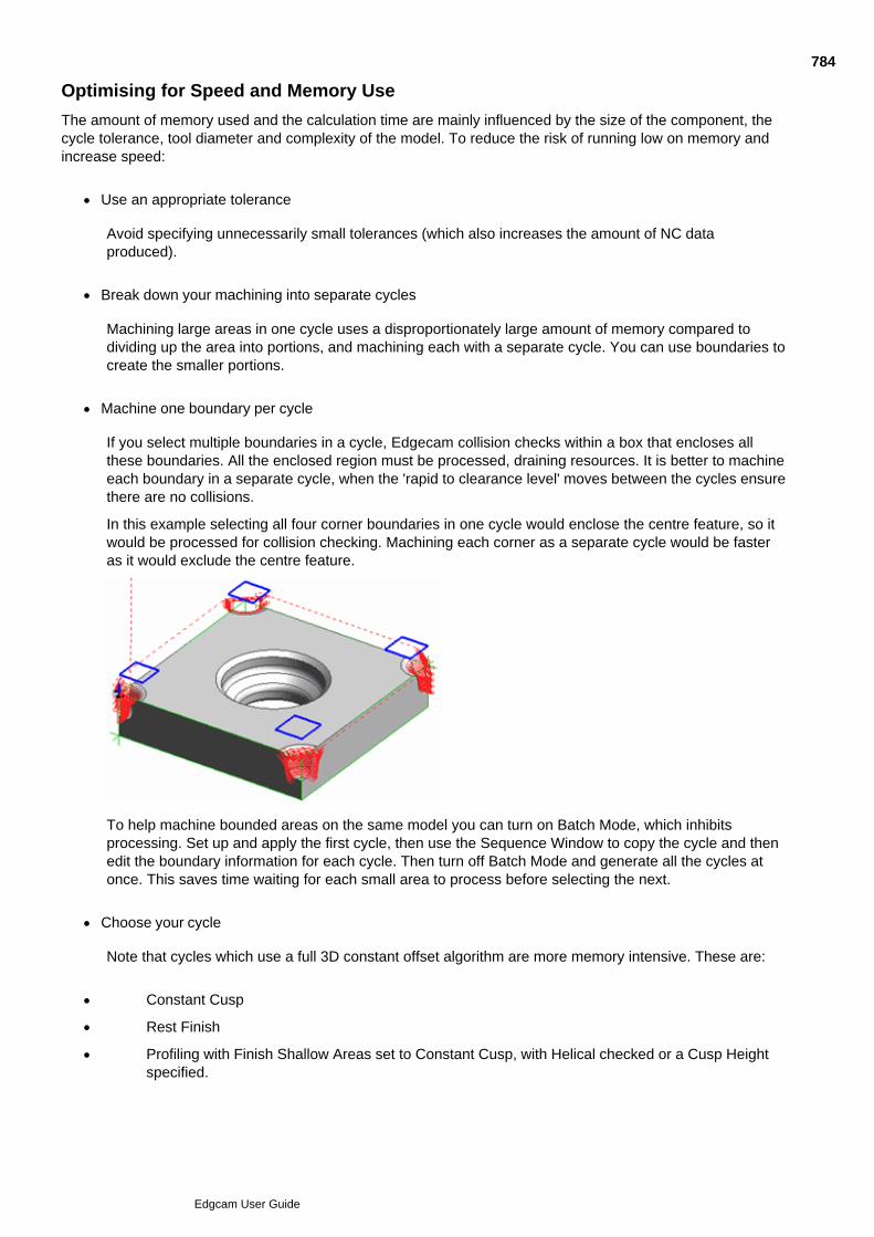
Optimising for Speed and Memory Use
The amount of memory used and the calculation time are mainly influenced by the size of the component, thecycle tolerance, tool diameter and complexity of the model. To reduce the risk of running low on memory andincrease speed:
Use an appropriate tolerance
Avoid specifying unnecessarily small tolerances (which also increases the amount of NC dataproduced).
Break down your machining into separate cycles
Machining large areas in one cycle uses a disproportionately large amount of memory compared todividing up the area into portions, and machining each with a separate cycle. You can use boundaries tocreate the smaller portions.
Machine one boundary per cycle
If you select multiple boundaries in a cycle, Edgecam collision checks within a box that encloses allthese boundaries. All the enclosed region must be processed, draining resources. It is better to machineeach boundary in a separate cycle, when the 'rapid to clearance level' moves between the cycles ensurethere are no collisions.
In this example selecting all four corner boundaries in one cycle would enclose the centre feature, so itwould be processed for collision checking. Machining each corner as a separate cycle would be fasteras it would exclude the centre feature.
To help machine bounded areas on the same model you can turn on Batch Mode, which inhibitsprocessing. Set up and apply the first cycle, then use the Sequence Window to copy the cycle and thenedit the boundary information for each cycle. Then turn off Batch Mode and generate all the cycles atonce. This saves time waiting for each small area to process before selecting the next.
Choose your cycle
Note that cycles which use a full 3D constant offset algorithm are more memory intensive. These are:
Constant Cusp
Rest Finish
Profiling with Finish Shallow Areas set to Constant Cusp, with Helical checked or a Cusp Heightspecified.
784
Edgcam User Guide

Cycles that use less memory include:
Parallel Lace
Profiling (without Finish Shallow)
Use large ball or bull nose tools
For example a 1mm (0.04”) tool will use 10 times the memory of a 10mm (0.4”) tool. An Endmill (sharpcorner) will use more memory than a Bull or Ball nose cutter.
Periodically clear the Undo / Redo Buffer
At convenient times save and re-load the part to clear the buffer. The buffer stores the previous state ofthe toolpaths each time you edit, regenerate or add commands. This is a very useful, but whengenerating large surface toolpaths it can be expensive on memory.
785
Edgcam User Guide
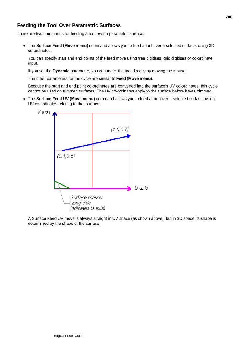
Feeding the Tool Over Parametric Surfaces
There are two commands for feeding a tool over a parametric surface:
The Surface Feed (Move menu) command allows you to feed a tool over a selected surface, using 3Dco-ordinates.
You can specify start and end points of the feed move using free digitises, grid digitises or co-ordinateinput.
If you set the Dynamic parameter, you can move the tool directly by moving the mouse.
The other parameters for the cycle are similar to Feed (Move menu).
Because the start and end point co-ordinates are converted into the surface’s UV co-ordinates, this cyclecannot be used on trimmed surfaces. The UV co-ordinates apply to the surface before it was trimmed.
The Surface Feed UV (Move menu) command allows you to feed a tool over a selected surface, usingUV co-ordinates relating to that surface:
A Surface Feed UV move is always straight in UV space (as shown above), but in 3D space its shape isdetermined by the shape of the surface.
786
Edgcam User Guide
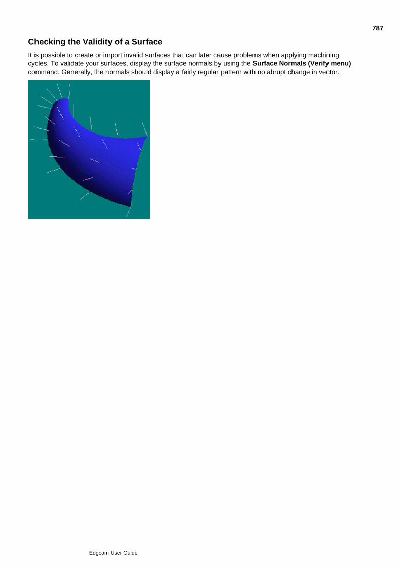
Checking the Validity of a Surface
It is possible to create or import invalid surfaces that can later cause problems when applying machiningcycles. To validate your surfaces, display the surface normals by using the Surface Normals (Verify menu)command. Generally, the normals should display a fairly regular pattern with no abrupt change in vector.
787
Edgcam User Guide

Problem Areas
Degenerate surfaces (surfaces that cross over themselves)
Degenerate surface curves on trimmed surfaces (surface curve intersects with itself)
Tangent continuous corners on Coons Patches
788
Edgcam User Guide

Pre-Version 10.5 Five Axis Milling
Three basic types of cycle are available in Pre-V10.5 Five Axis Milling:
Five Axis Areaclear (Mill Cycles menu)
Five Axis Drill (Mill Cycles menu)
Five Axis Slot (Mill Cycles menu)
These milling cycles each have several machining strategies that you can select.
The Pre-V10.5 Five Axis Milling module can simultaneously interpolate three linear and two independent rotaryaxes, from the following axes:
X - linear movement in the X axis
Y - linear movement in the Y axis
Z - linear movement in the Z axis
A - rotation about the X axis
B - rotation about the Y axis
C - rotation about the Z axis
Each Code Generator specifies exactly which axes are available to a particular machine tool.
Important Notes:
Tool orientation is not taken into account when you generate and display a solid model.
There is no automatic gouge detection.
Islands are not recognised when generating toolpaths for the Five Axis Areaclear cycle.
Surface groups may not be selected to be machined, as they will usually contain more that one surface.
See Also
Areaclearance in Pre-V10.5 Five Axis
Drilling in Pre-V10.5 Five Axis
Slotting in Pre-V10.5 Five Axis
Specifying Pre-V10.5 Five Axis Cycle Parameters
789
Edgcam User Guide

Areaclearance in Pre-V10.5 Five Axis
Use the Five Axis Areaclear (Mill Cycles menu) command to machine all Edgecam surface types,using endmill, bullnose or ballnose cutters.
To use the Five Axis Areaclear cycle
You must have a surface ready to be machined, and you should be familiar with the Areaclear cycle.
Select the Five Axis Areaclear (Mill Cycles menu) command. A box appears containing theparameters for the cycle.
1.
Set the parameters for the cycle and click on OK.2.
Digitise the surface.3.
Digitise the first corner of the surface.4.
Digitise the second corner of the surface.5.
Select the side of the surface for the toolpath.6.
Perform a Finish.7.
The system now generates the toolpath.
See Also
Using Pre-V10.5 Five Axis Areaclear Strategies
790
Edgcam User Guide
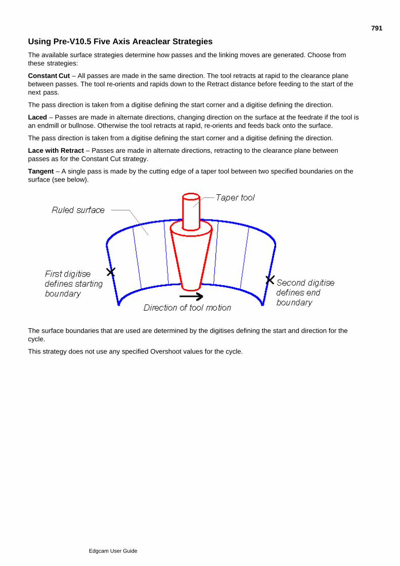
Using Pre-V10.5 Five Axis Areaclear Strategies
The available surface strategies determine how passes and the linking moves are generated. Choose fromthese strategies:
Constant Cut – All passes are made in the same direction. The tool retracts at rapid to the clearance planebetween passes. The tool re-orients and rapids down to the Retract distance before feeding to the start of thenext pass.
The pass direction is taken from a digitise defining the start corner and a digitise defining the direction.
Laced – Passes are made in alternate directions, changing direction on the surface at the feedrate if the tool isan endmill or bullnose. Otherwise the tool retracts at rapid, re-orients and feeds back onto the surface.
The pass direction is taken from a digitise defining the start corner and a digitise defining the direction.
Lace with Retract – Passes are made in alternate directions, retracting to the clearance plane betweenpasses as for the Constant Cut strategy.
Tangent – A single pass is made by the cutting edge of a taper tool between two specified boundaries on thesurface (see below).
The surface boundaries that are used are determined by the digitises defining the start and direction for thecycle.
This strategy does not use any specified Overshoot values for the cycle.
791
Edgcam User Guide

Drilling in Pre-V10.5 Five Axis
Use the Five Axis Drill (Mill Cycles menu) command to drill points on a surface. Drilling takes placenormal to the surface at the drill point.
To use the Five Axis Drill cycle
You must have a surface ready to be machined, and you should be familiar with the Drill cycle.
Select the Five Axis Drill (Mill Cycles menu) command. A box appears containing the parametersfor the cycle.
1.
Set the parameters for the cycle and click on OK.2.
Digitise the surface.3.
Select the side of the surface for the toolpath.4.
Perform a Finish.5.
Digitise one or more locations to drill.6.
Perform a Finish.7.
The system now generates the toolpath.
See Also
Using Pre-V10.5 Five Axis Drill Strategies
792
Edgcam User Guide

Using Pre-V10.5 Five Axis Drill Strategies
The available drilling strategies are:
Drill – The tool retracts at the rapid rate between pecks and on completion.
Chipbreak – The tool retracts a short distance at the rapid rate between pecks and on completion.
Ream – The tool retracts at the feed rate between pecks and on completion.
Bore – The boring tool centres itself in the hole and retracts at the rapid rate between pecks.
See under Drilling, Reaming and Boring for further information on drilling cycles.
793
Edgcam User Guide

Slotting in Pre-V10.5 Five Axis
Use the Five Axis Slot (Mill Cycles menu) command to machine a surface curve. The tool is heldnormal to the surface at all points along the curve. To use the Five Axis Slot cycle
You must have a surface ready to machine, and you should be familiar with the Slot cycle.
Select the Five Axis Slot command. A box appears containing the parameters for the cycle.1.
Set the parameters for the cycle.2.
Click on OK to accept the parameters.3.
Digitise the surface curve.4.
Select the side of the surface on which to generate the toolpath. Press F1 to toggle between the twosides.
5.
Perform a Finish.6.
The toolpath is now generated.
See Also
Using Five Axis Slot Strategies
794
Edgcam User Guide

Using Pre-V10.5 Five Axis Slot Strategies
The available machining strategies are:
On – This drives the contact point of the tool along the surface curve. The start point is the end of the curvenearest to the digitise selecting the curve for the cycle.
Climb – The toolpath is offset to the left of the direction of travel.
Conventional – The toolpath is offset to the right of the direction of travel.
Note that the offset follows these rules:
Endmills are offset by the Tool Radius.
For other tools:
Depth parameter = 0 Tool is offset by Tool Radius plus any specified Offsetvalue.
Negative Depth parameter = Tool orCorner Radius
Tool is offset by Tool Radius plus any specified Offsetvalue (not endmills).
Negative Depth parameter< Tool or Corner Radius
For ballnose and bullnose cutters only.The offset is calculated for the point of tool contact.
For example, Depth = -5, Tool Radius = 2, Corner Radius = 1.
The negative Depth is greater than either the Tool or Corner Radius, so the tool is offset by the Tool Radiusplus any specified Offset value.
795
Edgcam User Guide
Specifying Pre-V10.5 Five Axis Cycle Parameters
The parameters for the cycle are:
Strategy – See the specific strategy types for each cycle.
Final Retract – Check this box to insert a move to the retract distance.
True Position – Check this box to force the machine tool controller to hit specified parts of the toolpath.
After the toolpath has been generated, you can specify those portions of the toolpath that are to be in TRUEPOSITION mode.
When you generate the CNC code for the machining cycle, the system forces the tool to pass through the co-ordinates of each TRUE POSITION segment of the toolpath.
Partial – Check this box to machine part of a surface within a digitised surface curve.
Canned Cycle – Check this box to use controller canned cycles. Leave blank to use Edgecam’s CNC code.
Feedrate – Specifies the rate of movement in the workplane.
Plunge Feed – Specifies the rate of movement in the direction of the tool axis.
Link Feed – Specifies the rate of movement for each linking move between passes. If this is not specified,Plunge Feed is used.
Speed – Specifies the tool spindle speed.
Cusp Height – A method of determining the surface finish. Specify the maximum height of material to be leftbetween passes.
Number of Passes – A method of determining the surface finish. Specify the number of passes over theselected surface.
Tolerance – Specifies the maximum deviation of the generated toolpath from the selected surface.
Step Distance – (Areaclear only) This modifier allows you to split the moves by the specified distance. This isnecessary for machines that do not resolve the rotary axes with the linear axes.
Stay at Depth – (Areaclear and Slot only). This stops the cycle from retracting between passes before movinginto position.
Lead In / Out tabs – Specify the Feedrate and Angle at which the tool approaches or leaves the surface.Length specifies the distance from the surface up to which the Lead In or Lead Out parameters operate. If theFeedrate is not specified, the system uses the Plunge Feed rate instead.
See Also
Specifying Pre-V10.5 Five Axis Tool Parameters
Specifying Pre-V10.5 Five Axis Depth Parameters
796
Edgcam User Guide
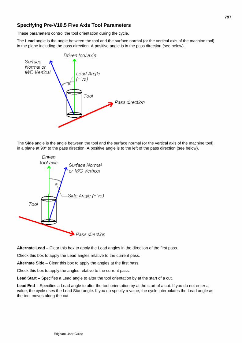
Specifying Pre-V10.5 Five Axis Tool Parameters
These parameters control the tool orientation during the cycle.
The Lead angle is the angle between the tool and the surface normal (or the vertical axis of the machine tool),in the plane including the pass direction. A positive angle is in the pass direction (see below).
The Side angle is the angle between the tool and the surface normal (or the vertical axis of the machine tool),in a plane at 90° to the pass direction. A positive angle is to the left of the pass direction (see below).
Alternate Lead – Clear this box to apply the Lead angles in the direction of the first pass.
Check this box to apply the Lead angles relative to the current pass.
Alternate Side – Clear this box to apply the angles at the first pass.
Check this box to apply the angles relative to the current pass.
Lead Start – Specifies a Lead angle to alter the tool orientation by at the start of a cut.
Lead End – Specifies a Lead angle to alter the tool orientation by at the start of a cut. If you do not enter avalue, the cycle uses the Lead Start angle. If you do specify a value, the cycle interpolates the Lead angle asthe tool moves along the cut.
797
Edgcam User Guide

Side Start – Specifies a Side angle to alter the tool orientation by at the start or end of a cut.
Side End – Specifies a Side angle to alter the tool orientation by at the end of a cut. If you do not enter a value,the cycle uses the Side Start angle. If you do specify a value, the cycle interpolates the Side angle as the toolmoves along the cut.
Relative To – Select the axis that the Lead and Side angles are taken from.
Normal – To use the angles relative to the surface normals.
Vertical – To use the angles relative to the machine tool’s vertical axis (not the same as the driven tool axis).
798
Edgcam User Guide

Specifying Pre-V10.5 Five Axis Depth Parameters
Clearance – Specifies a plane at an absolute height for the tool to move to during and after the cycle. If you donot specify a value you are asked to digitise an entity. The Clearance plane is set to the height of this entity.
Retract – This must be specified, and defines the distance the tool feeds towards and away from the surface,measured relative to the surface normal.
Depth – Specifies a depth of cut for the cycle, measured relative to the surface normal at each point.
Clearance Plane – Specifies the CPL to be used for the Clearance plane. Leave blank to use the XY plane ofthe Initial CPL. Select the box to be offered a choice of all available CPLs when entering co-ordinate data forthe cycle.
799
Edgcam User Guide
4/5 Axis Simultaneous Milling Overview
4/5 Axis Simultaneous Milling is based on the Five Axis Milling cycle. This allows you to simultaneously drivethe tool in up to five axes (that is three linear axes and two rotary axes). This means for example that the toolcan always be kept normal to a surface, to improve the finish, or that the tool can be fed into complex cavities,being tilted to avoid gouging.
Note: for 4/5 Axis Simultaneous Milling you need a Mill or a Mill/Turn code generator based on one of theadaptive templates.
Typical applications of the cycle include:
SWARF Machining, where thetool is laid along a face,following the changes in theface orientation, and cutting ison the side of the tool.
5 Axis Finishing, where the tool axisis kept normal to the surface for aconsistent finish.
4 Axis RotaryMachining
For each of these techniques (and Five Axis Curve machining) there is an operation. The operation quickly setsup the Five Axis cycle for the technique, as an alternative to you having to set up the cycle manually.
To remove bulk material you can make multiple copies of cuts.
Note that Code Generators may be set up to use Inverse Time Feedrates for 4/5 Axis Simultaneous Milling.More details are provided in the Code Wizard help.
800
Edgcam User Guide

Using the Five Axis Cycle
Use Mill Cycles Five Axis to open the Five Axis milling dialog.
Here are details on the using the cycle and the cycle dialog's settings (you can also access this help by clickingthe Help button in the dialog):
801
Edgcam User Guide

802
Edgcam User Guide

803
Edgcam User Guide

804
Edgcam User Guide

805
Edgcam User Guide

Five Axis Dialog Leads tab
806
Edgcam User Guide

807
Edgcam User Guide

808
Edgcam User Guide

809
Edgcam User Guide
Setting the Surface Side to Machine
If you are using face features as the surfaces for a Five Axis cycle, the correct side will always be machined(this is because the face features are derived from solid models, so the 'material' side is always known).
However if you are using surfaces, you might find the wrong side being machined, perhaps the underneathrather than the top:
In this case you could use Surface menu Surface Group, and in the Surface Group dialog set SideSelection to Prompt.
After digitising the surface(s) to form the group, you would then click on the material side (here this is the topface, as indicated by the red lines):
If you then select this surface group as the drive surface for the cycle, the machining will be on the correct side:
810
Edgcam User Guide
What is Rotary Milling?
Rotary Milling is the ability to perform 2D and 2.5D machining cycles around or on the end of a cylinder.
Note that Rotary Milling is not supported with non-intersecting or nutated rotary axes, or with a head-headconfigurations.
When performing radial machining (around the cylinder), the tool is restricted to moving parallel to and aroundthe rotary axis. The tool is always oriented radially to the centreline of the rotary axis.
Radial Machining - Rotary Mode Radial Machining - Planar Mode
When performing axial machining (on the end of the cylinder), the tool's Z axis is parallel to the rotary axis.
Note that Edgecam Rotary Milling only supports table-mounted axes. Whether one or both of these machiningoptions is open to you is dependent on your machine tool.
Rotary Milling Examples
811
Edgcam User Guide

Creating the Sequence Considerations
In addition to the normal considerations when setting the Machine Datum:
Note: The axis of rotation on the machine must align with the unwrapped geometry, or else you will notbe able to machine the geometry.
812
Edgcam User Guide
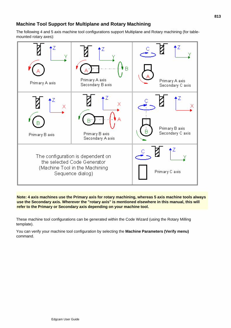
Machine Tool Support for Multiplane and Rotary Machining
The following 4 and 5 axis machine tool configurations support Multiplane and Rotary machining (for table-mounted rotary axes):
Note: 4 axis machines use the Primary axis for rotary machining, whereas 5 axis machine tools alwaysuse the Secondary axis. Wherever the "rotary axis" is mentioned elsewhere in this manual, this willrefer to the Primary or Secondary axis depending on your machine tool.
These machine tool configurations can be generated within the Code Wizard (using the Rotary Millingtemplate).
You can verify your machine tool configuration by selecting the Machine Parameters (Verify menu)command.
813
Edgcam User Guide
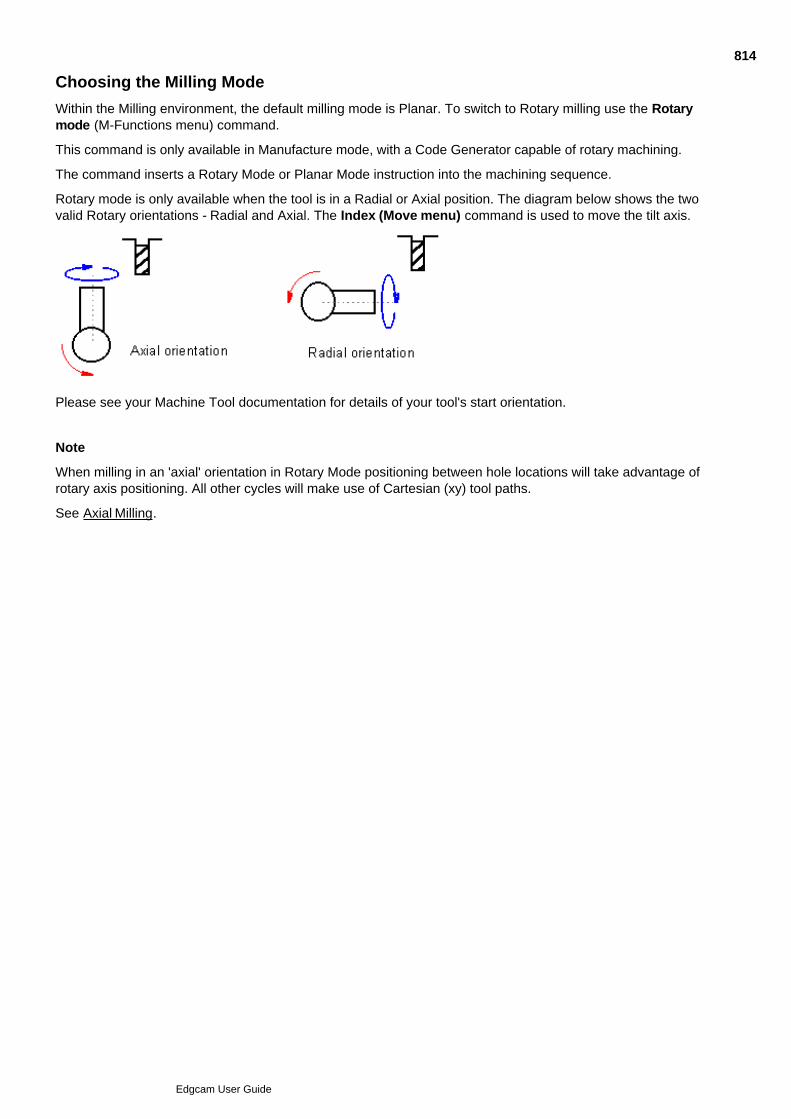
Choosing the Milling Mode
Within the Milling environment, the default milling mode is Planar. To switch to Rotary milling use the Rotarymode (M-Functions menu) command.
This command is only available in Manufacture mode, with a Code Generator capable of rotary machining.
The command inserts a Rotary Mode or Planar Mode instruction into the machining sequence.
Rotary mode is only available when the tool is in a Radial or Axial position. The diagram below shows the twovalid Rotary orientations - Radial and Axial. The Index (Move menu) command is used to move the tilt axis.
Please see your Machine Tool documentation for details of your tool's start orientation.
Note
When milling in an 'axial' orientation in Rotary Mode positioning between hole locations will take advantage ofrotary axis positioning. All other cycles will make use of Cartesian (xy) tool paths.
See Axial Milling.
814
Edgcam User Guide

Milling in Rotary Mode
Before attempting a rotary milling operation, ensure that you have selected:
a rotary Code Generator Machine Tool
if necessary, use the Index (Move menu) command to tilt the rotary axis into the Radial or Axial position(5 axis machines only)
the Rotary mode (M-Function menu) command.
The following commands are available for Rotary Milling:
Angular (Move menu)
See Also
Moving Around the Rotary Axis
Resetting the Rotary Datum
Rotating Machining Instructions
Configuring the Rotary Machining Output
Rules Used to Determine the Angular Position of the Tool
Axial Milling
815
Edgcam User Guide
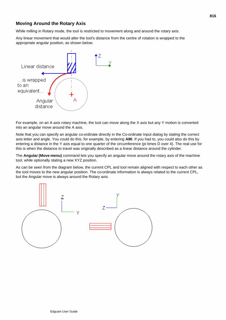
Moving Around the Rotary Axis
While milling in Rotary mode, the tool is restricted to movement along and around the rotary axis.
Any linear movement that would alter the tool's distance from the centre of rotation is wrapped to theappropriate angular position, as shown below.
For example, on an A axis rotary machine, the tool can move along the X axis but any Y motion is convertedinto an angular move around the A axis.
Note that you can specify an angular co-ordinate directly in the Co-ordinate Input dialog by stating the correctaxis letter and angle. You could do this, for example, by entering A90. If you had to, you could also do this byentering a distance in the Y axis equal to one quarter of the circumference (pi times D over 4). The real use forthis is when the distance to travel was originally described as a linear distance around the cylinder.
The Angular (Move menu) command lets you specify an angular move around the rotary axis of the machinetool, while optionally stating a new XYZ position.
As can be seen from the diagram below, the current CPL and tool remain aligned with respect to each other asthe tool moves to the new angular position. The co-ordinate information is always related to the current CPL,but the Angular move is always around the Rotary axis.
816
Edgcam User Guide
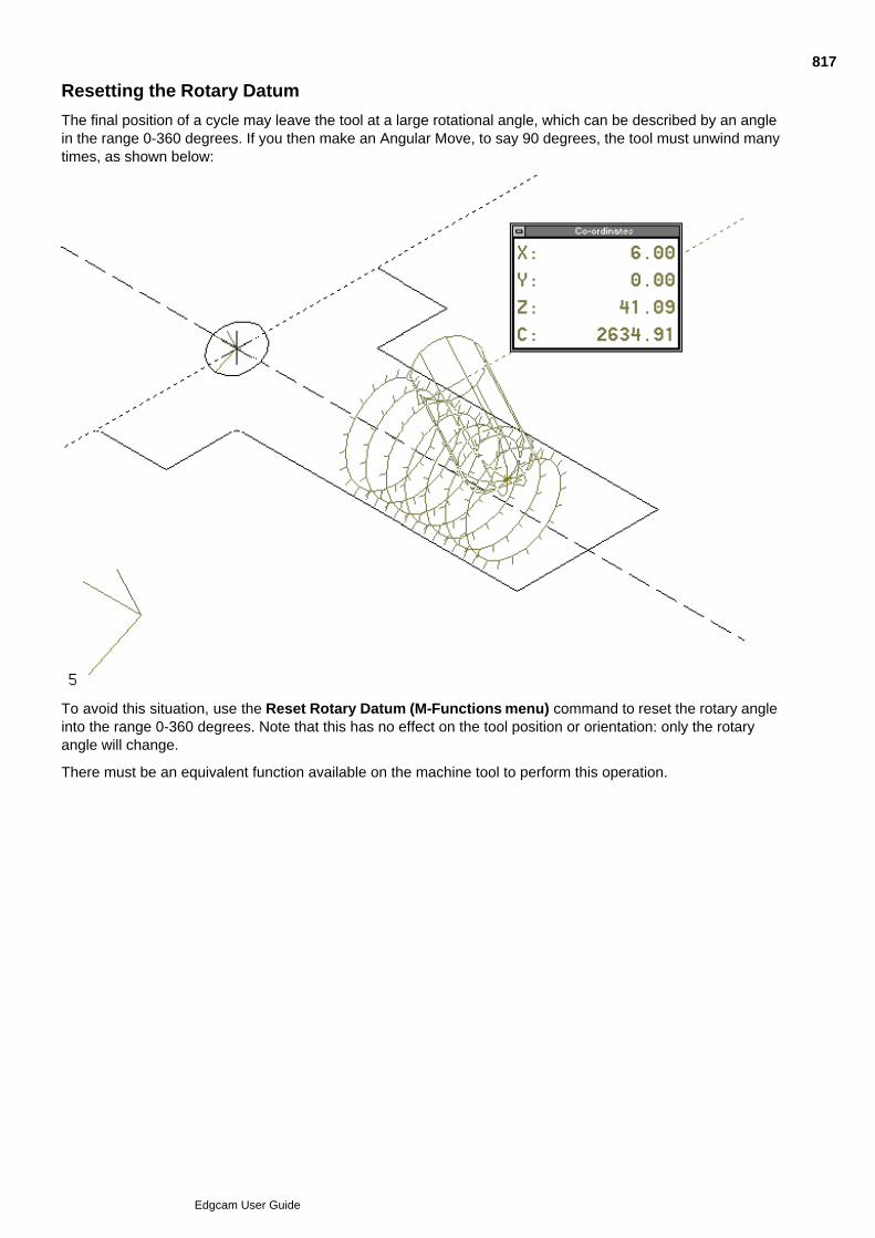
Resetting the Rotary Datum
The final position of a cycle may leave the tool at a large rotational angle, which can be described by an anglein the range 0-360 degrees. If you then make an Angular Move, to say 90 degrees, the tool must unwind manytimes, as shown below:
To avoid this situation, use the Reset Rotary Datum (M-Functions menu) command to reset the rotary angleinto the range 0-360 degrees. Note that this has no effect on the tool position or orientation: only the rotaryangle will change.
There must be an equivalent function available on the machine tool to perform this operation.
817
Edgcam User Guide
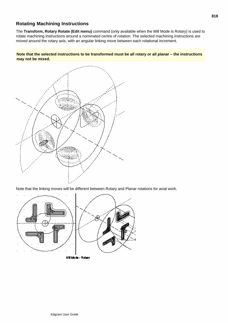
Rotating Machining Instructions
The Transform, Rotary Rotate (Edit menu) command (only available when the Mill Mode is Rotary) is used torotate machining instructions around a nominated centre of rotation. The selected machining instructions aremoved around the rotary axis, with an angular linking move between each rotational increment.
Note that the selected instructions to be transformed must be all rotary or all planar – the instructionsmay not be mixed.
Note that the linking moves will be different between Rotary and Planar rotations for axial work.
818
Edgcam User Guide
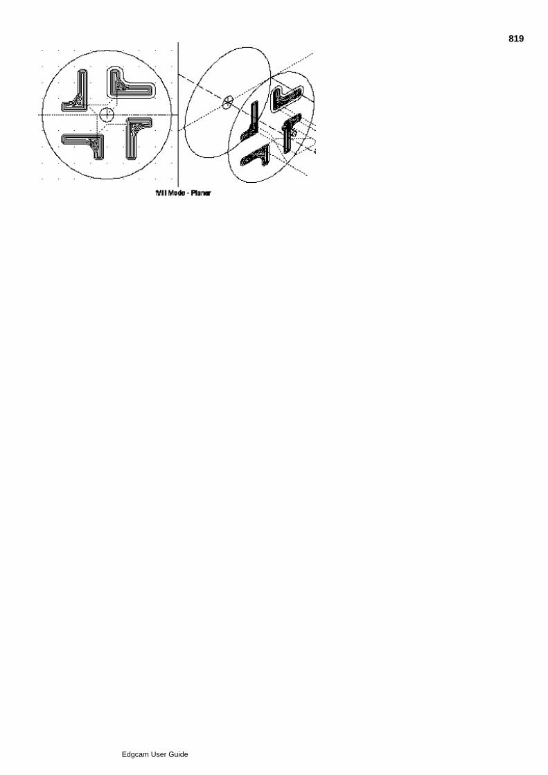
819
Edgcam User Guide

Configuring the Rotary Machining Output
The Code Generator/ Wizard can be configured to output different co-ordinate information depending upon themachine tool type:
Output relative to tool depth - a common output method for milling machines. The main effect is thatarcs that are machined at a different radius to the unwrapped envelope become elliptical and aretherefore output as a series of feed moves.
Output relative to geometry level (Wrapped radius) - a common output method for lathes and formachines that can store the radius information and output all toolpath data relative to that level. The maineffect is that all arc information is output at the Wrapping radius regardless of tool depth.
Output relative to the unwrapped (Planar) geometry - for machines with controllers that can wrapplanar toolpaths directly (all CNC information is output as if Planar mode was active). An examplemachine tool that uses this type of output is the Bostomatic.
For more information on how to select these features, see the Code Generator and Code Wizarddocumentation.
820
Edgcam User Guide

Rules Used to Determine the Angular Position of the Tool
For toolpath moves with no Depth parameter values entered (Feed, Rapid etc.), the Wrap radiusparameter determines the angular position. If you leave the Wrap Radius parameter blank, the systemuses the current tool position.
1.
For cycles that use Depth parameters (for example, Face Mill), the cycle level determines the WrapRadius.
2.
For cycles that use entities to determine the toolpath, the level of the geometry determines the WrapRadius. This means that you keep the correct angular position with respect to the selected geometry.
3.
821
Edgcam User Guide
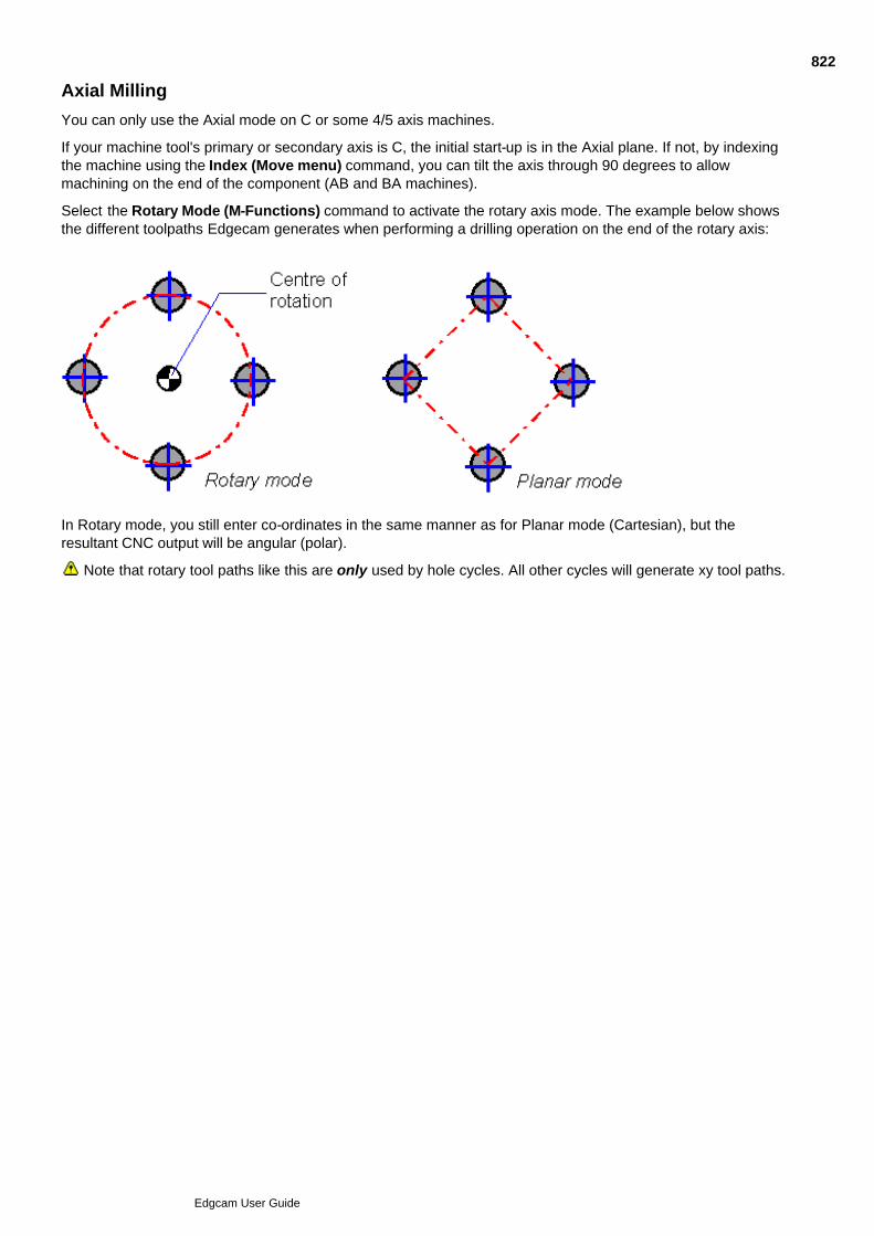
Axial Milling
You can only use the Axial mode on C or some 4/5 axis machines.
If your machine tool's primary or secondary axis is C, the initial start-up is in the Axial plane. If not, by indexingthe machine using the Index (Move menu) command, you can tilt the axis through 90 degrees to allowmachining on the end of the component (AB and BA machines).
Select the Rotary Mode (M-Functions) command to activate the rotary axis mode. The example below showsthe different toolpaths Edgecam generates when performing a drilling operation on the end of the rotary axis:
In Rotary mode, you still enter co-ordinates in the same manner as for Planar mode (Cartesian), but theresultant CNC output will be angular (polar).
Note that rotary tool paths like this are only used by hole cycles. All other cycles will generate xy tool paths.
822
Edgcam User Guide

Angular Co-ordinate Input in Manufacture Mode
When in rotary mode, co-ordinate input can be used for entering an angular position.
For example, you can create a feed move by entering 'Y50B90' into the Co-ordinate input dialog. The tool willfeed to Y50 and rotate to B90. Note that the Wrap radius must be set correctly within the Feed dialog.
823
Edgcam User Guide

Locking the View Down the Tool Axis
The ‘Track CPL’ port is a selected user-defined port which is always orientated to view down onto the activeCPL, including Wrap CPLs.
Access to the Track CPL port is through the Track CPL parameter in the Drawing, Configure (View menu)dialog.
Select the appropriate user-defined port to become the new Track CPL port.
Select ‘None’ to de-activate the port (if it is the current Track CPL port).
Note that you must have at least one user-defined port to set a Track CPL port, since standard ports cannot bere-orientated.
824
Edgcam User Guide

Indexing to CPLs
Use Move menu Index to change your working CPL in Manufacture mode.
Here are details on using the command (you can also access this help by clicking the Help button in the Indexdialog):
825
Edgcam User Guide
Slotting
To slot non-profile geometry, use the Slot (Mill Cyclesmenu) command.
This has two modes of operation specified by the Strategy parameter: 2D and 3D.
You can also use the Profile cycle with a zero offset to slot profiles.
In operation, the tool rapid moves to a position vertically above the start of the slot. It then rapids down until itreaches the Retract height from the slot. The tool then feeds down to Depth and starts to move along the slot.
After selecting the Slot cycle, you are prompted to select a Strategy for the cycle.
Choose between:
2D - Drives the tool along planar entities such as lines, arcs and continuous entities.
3D - Drives the tool along curves and 3D continuous entities.
Once you have selected the Strategy, the parameters for the cycle are displayed.
To combine several commands when slotting, use Slotting (Operations menu) . See OperationalProgramming in Milling for details of using operations.
See Also
Slotting in 2D
Slotting in 3D
Choosing Parameters for Slotting
826
Edgcam User Guide

Slotting in 2D
Select the Slot (Mill Cycles menu) command and set the Strategy parameter to 2D.
You can now select the remaining parameters for the cycle. See Choosing Parameters for Slotting.
827
Edgcam User Guide

Slotting in 3D
Select the Slot (Mill Cycles menu) command and set the Strategy parameter to 3D.
These parameters are unique to 3D slotting:
Link Control - If you are slotting more than one entity, you can choose the method of producing link moves:
Shortest - Produces a 3D linear feed move to the start of the next slot.
Retract - The tool rapids vertically to the Clearance height, rapids in the workplane to the start of the next slotand feeds down to Depth.
Tolerance - If a Continuous entity contains an arc that does not lie in either the XY, XZ or YZ planes, theresultant toolpath will break the arc into a series of small linear moves which lie within this tolerance. You can now select the remaining parameters for the cycle. See Choosing Parameters for Slotting.
828
Edgcam User Guide

Choosing Parameters for Slotting
The Slot cycle provides these parameters:
Feedrate, Plunge Feed and Speed are the standard feeds and speeds for the cycle.
Depth parameters are covered under Depth Parameters. If using 3D Slotting, use the Relative Depthparameter instead of the Depth parameter.
Name - Specifies the name of the toolpath.
829
Edgcam User Guide
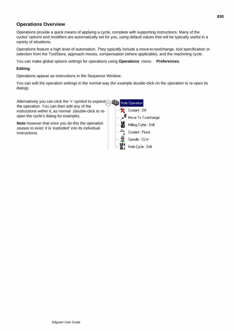
Operations Overview
Operations provide a quick means of applying a cycle, complete with supporting instructions. Many of thecycles' options and modifiers are automatically set for you, using default values that will be typically useful in avariety of situations.
Operations feature a high level of automation. They typically include a move-to-toolchange, tool specification orselection from the ToolStore, approach moves, compensation (where applicable), and the machining cycle.
You can make global options settings for operations using Operations menu Preferences.
Editing
Operations appear as instructions in the Sequence Window.
You can edit the operation settings in the normal way (for example double-click on the operation to re-open itsdialog).
Alternatively you can click the '+' symbol to expandthe operation. You can then edit any of theinstructions within it, as normal (double-click to re-open the cycle's dialog for example).
Note however that once you do this the operationceases to exist; it is 'exploded' into its individualinstructions.
830
Edgcam User Guide

Using Operations - General
Here are the general steps in using any other operation:
Select the operation command from the menu.1.
Complete the dialog for setting the 'Index CPL', 'Tool Orientation' and 'Mode', if this appears. The dialogonly appears if you are using a Milling operation in a Mill/Turn environment. For full details click thedialog's Help button.
2.
Follow the status bar prompts; digitise the features to be machined for example.3.
Complete the operation's dialog that then appears. You specify, for example, the % Stepover and CutIncrement for roughing cycles.
For 'new style' operations Roughing, Profiling, Flat Land Finishing, Chamfer, when completing the dialogsyou see explanatory illustrations and animations; you can rest the cursor on these to see text-basedinformation popups.
For any other operations, click the dialog's Help button for information.
4.
You can apply an operation to a feature directly (where applicable):
Show the Features Window and right-click on the feature.1.
In the subsequent shortcut menu click the operation option you want to apply to the feature.2.
Follow steps 2 to 4 above.3.
831
Edgcam User Guide

Using Batch Mode for Operations
You may find that some operations (usually Surface operations) take some time to generate the appropriatetoolpaths.
In this case you can:
Activate the Batch Mode command.1.
Create the operations.2.
De-activate the Batch Mode command.3.
Generate the toolpaths for the operations using the Regenerate command.4.
While Batch Mode is active, no toolpaths or screen tool simulations are displayed.
Note that if you attempt to generate NC code, no code is produced for any batched operations other than acomment.
832
Edgcam User Guide

Standard Sequence for Milling Operations
These are the machining instructions performed as standard for each operation:
Coolant Off – (If selected in Preferences)
Spindle Stop – (If selected in Preferences)
Rapid to Toolchange
Toolchange
Coolant – (From Preferences)
Spindle – (From Preferences)
None of these instructions will be performed if the current tool is ‘identical’ to the tool definition for theoperation. A milling tool is considered to be identical if the tool diameter, corner radius, tool type and turretposition are the same.
833
Edgcam User Guide

Specifying Preferences for Milling Operations
The Preferences (Operations menu) command allows you to specify a range of preferred values thatwill apply to all subsequent machining cycles and operations. You must have initialised a machining sequenceor you will not be allowed to specify any values.
For details on value click the Help button in the Operation Preferences dialog, that the command opens.
834
Edgcam User Guide

Using the Tool Store in Operations
Rather than setting the individual tool parameters in operations, you can retrieve tooling data by clicking theFind button and selecting a tool from the ToolStore dialog that opens.
835
Edgcam User Guide

Index Operation
The Index (Operations menu) command allows you to perform an incremental or absolute datum shiftto a specified angle or a selected datum.
See Also
Sequence of Instructions in the Index Operation
Using the Index Operation
836
Edgcam User Guide

Sequence of Instructions in the Index Operation
Index
Move Rapid to the specified Clearance value
Move Index to either the specified angle or datum
837
Edgcam User Guide

Using the Index Operation
Click on the Index Operation button .1.
Complete the dialog box for the operation. Click OK.2.
Edgecam now indexes the tool.
838
Edgcam User Guide

Hole Operation
The Hole (Operations menu) command allows you to combine several related drillingcommands in one instruction.
See Also
Sequence of Instructions in the Hole Operation
Using the Hole Operation
Hole Operation Termination
Hole Operation Preparation Strategy
Hole Cycle
839
Edgcam User Guide

Sequence of Instructions in the Hole Operation
Centre/Spot
[Standard Sequence]
Drill Cycle
Preparation*
[Standard Sequence]
Drill Cycle
Roughing
[Standard Sequence]
Drill Cycle
Finishing
[Standard Sequence]
M-Functions – Spindle (If Strategy = Tap – Direction derived by hand)
Drill/Bore/Tap Cycle
*Note that Preparation could occur after Roughing if you check the Preparation tab’s After Roughing box.See the Standard Sequence for Milling Operations for details of the standard sequence.
840
Edgcam User Guide

Using the Hole Operation
Click on the Hole Operation button.1.
Digitise one or more positions depending on the selection method you chose. Perform a Finish to stopselecting positions for the operation.
2.
Complete the dialog box for the operation. Click on OK.3.
Edgecam now generates the toolpaths for the hole operation, including any moves to position the tool.
Note on using the Hole operation with solid parts
When using the Hole operation on a solid part with a tool selected from the ToolStore, if the solid is updatedwith a different hole diameter, the tool will not be updated. A warning message is displayed giving the name ofthe tool and specifying that the ToolStore tool diameter and hole diameter do not match.
841
Edgcam User Guide
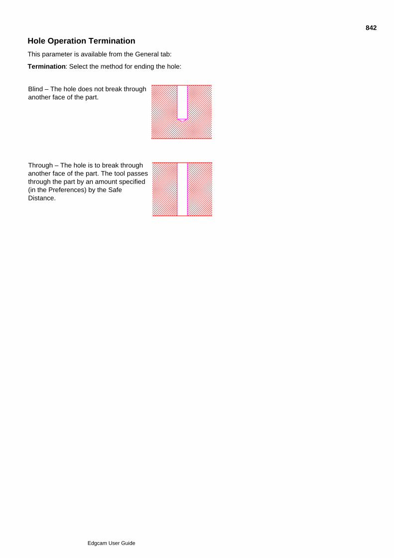
Hole Operation Termination
This parameter is available from the General tab:
Termination: Select the method for ending the hole:
Blind – The hole does not break throughanother face of the part.
Through – The hole is to break throughanother face of the part. The tool passesthrough the part by an amount specified(in the Preferences) by the SafeDistance.
842
Edgcam User Guide
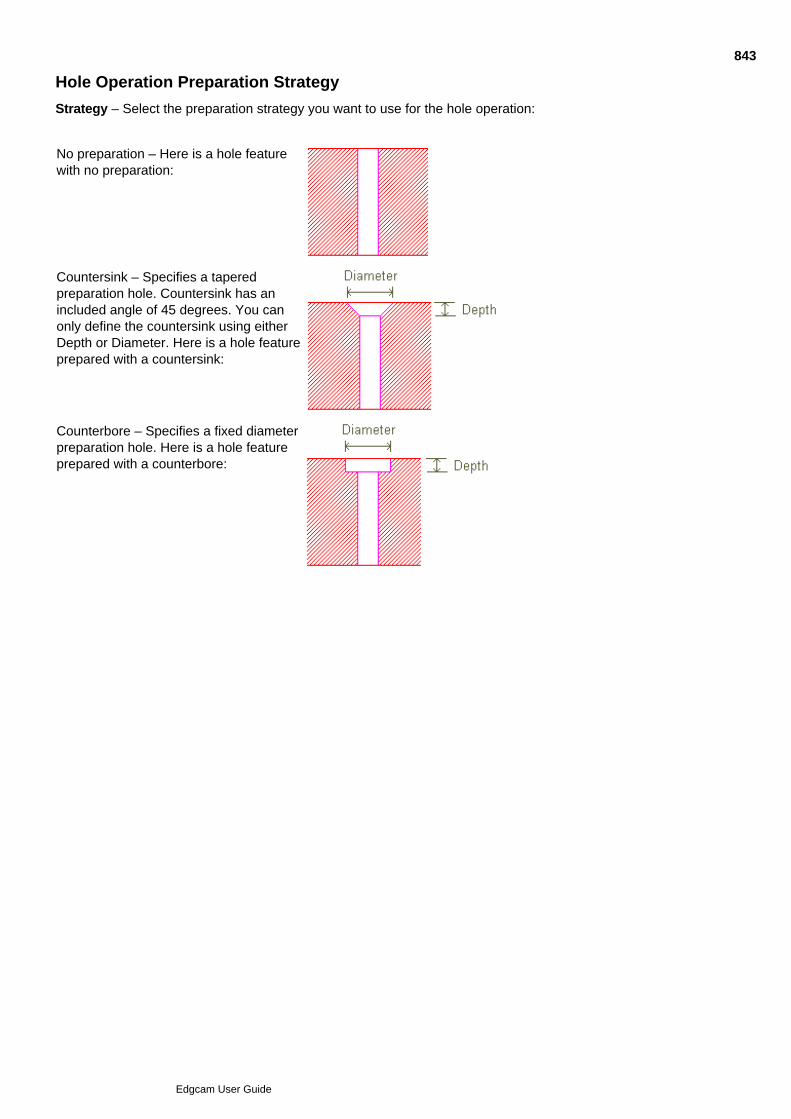
Hole Operation Preparation Strategy
Strategy – Select the preparation strategy you want to use for the hole operation:
No preparation – Here is a hole featurewith no preparation:
Countersink – Specifies a taperedpreparation hole. Countersink has anincluded angle of 45 degrees. You canonly define the countersink using eitherDepth or Diameter. Here is a hole featureprepared with a countersink:
Counterbore – Specifies a fixed diameterpreparation hole. Here is a hole featureprepared with a counterbore:
843
Edgcam User Guide

Profiling Operation
The Profiling (Operations menu) command allows you to use several commands together in oneoperation.
This operation supports Wireframe, Feature, Surface and Solid as input.
Please note that this operation was introduced in Edgecam Version 9.0, so:
Features created prior to Edgecam Version 9.0 are treated as wireframe. For full associativity, re-createthe features in the latest Edgecam version, before applying the operation.
Part files created in Edgecam prior to Version 9.0 may contain examples of the older supersededoperation. You might want to delete these operations and re-apply the new operation.
See Also
Operations Overview
Sequence of Instructions in the Profiling Operation
Using the Profiling Operation
Profiling Cycle
844
Edgcam User Guide

Sequence of Instructions in the Profiling Operation
Profiling
[Standard Sequence]
Profiling Cycle See the Standard Sequence for Milling Operations for details of the standard sequence.
845
Edgcam User Guide
Using the Profiling Operation
In the Operations menu or toolbar click Profiling Operation .1.
Digitise either the Wireframe profile(s), Features, Surfaces or Solid you wish to Profile. For wireframe youwill need to position the Start/Side Arrow on the side to be machined (otherwise this is automatic).
(When a Feature or Solid is selected the Depth values are Associative. Wireframe and Surface use anAbsolute Clearance and Level with an incremental Depth.)
2.
Perform a Finish.3.
Select a containment boundary if required4.
Perform a Finish.5.
Complete the dialog box for the operation. Click on OK.
Note that in the dialog you cannot set both an Offset value and an XY Offset value; you can only set oneor the other.
6.
Edgecam now generates the toolpaths for the profiling operation, including any moves to position the tool.
For surface geometry the operation allows blank level and depth fields. When no values are specified level anddepth are taken from the model.
Profile Material on the Left
This option is used to take advantage of the feature material side and to maintain associativity between thefeature and the Profile operation.
When manually identifying features, the direction of the profile is automatically selected such that thematerial is on the left. Checking the Profile Material on the Left option on the General tab of thePreferences (Operations menu) dialog will allow the machining operation to cut the correct side of thefeature without any further intervention from the user.
This method can be used on wireframe geometry by chaining the profile in the correct direction so as tomaintain the material on the left.
846
Edgcam User Guide

Chamfer Operation
The Chamfer (Operations menu) command generates a single profile pass byselecting the top profile of a chamfered edge.
Please note that this operation was introduced in Edgecam Version 9.0, so:
Features created prior to Edgecam Version 9.0 are treated as wireframe. For full associativity, re-createthe features in the latest Edgecam version, before applying the operation.
Part files created in Edgecam prior to Version 9.0 may contain examples of the older supersededoperation. You might want to delete these operations and re-apply the new operation.
See Also
Operations Overview
Sequence of Instructions in the Chamfer Operation
Using the Chamfer Operation
Chamfer Operation Notes
847
Edgcam User Guide

Sequence of Instructions in the Chamfer Operation
Chamfer[Standard Sequence]
Profiling Cycle See the Standard Sequence for Milling Operations for details of the standard sequence.
848
Edgcam User Guide

Using the Chamfer Operation
Click on the Chamfer Operation button.1.
Digitise the Wireframe profile(s) or Feature. Perform a Finish.
(When a Feature or Solid is selected the Clearance and Level are values are Associative and the Depthis incremental. Wireframe and Surface use an Absolute Clearance and Level with an incremental Depth.)
2.
If wireframe was selected position the Start/Side Arrow (this is automatic for features).3.
Complete the dialog box for the operation. Click on OK.4.
Edgecam now generates the toolpaths for the chamfer operation, including any moves to position the tool.
For surface geometry the operation allows blank level and depth fields. When no values are specified level anddepth are taken from the model.
Break Distance
The Profile selected for chamfering is assumed to be the top edge of the Chamfer (chamfer has beenmodelled). If the Profile represents the un-chamfered profile then the Break Distance modifier is used to cutinto the profile to produce the chamfer.
849
Edgcam User Guide
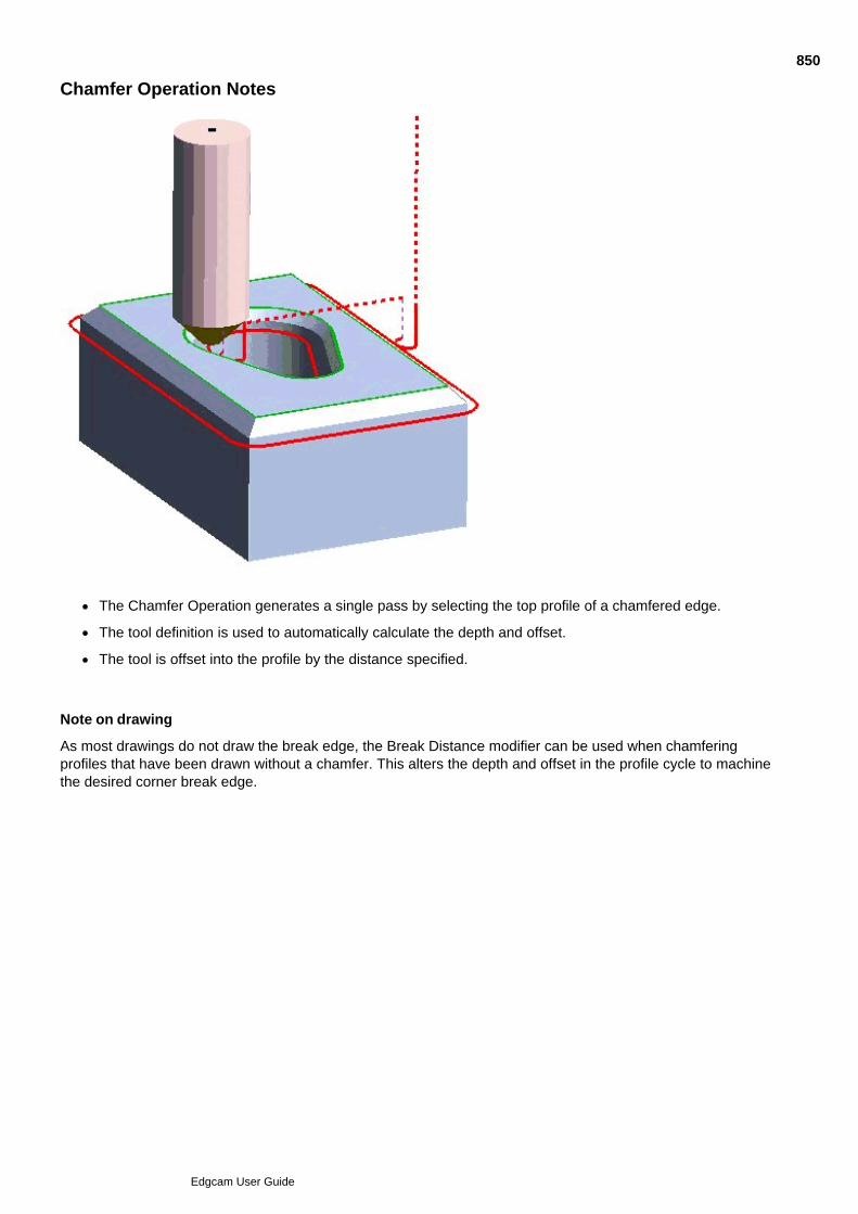
Chamfer Operation Notes
The Chamfer Operation generates a single pass by selecting the top profile of a chamfered edge.
The tool definition is used to automatically calculate the depth and offset.
The tool is offset into the profile by the distance specified.
Note on drawing
As most drawings do not draw the break edge, the Break Distance modifier can be used when chamferingprofiles that have been drawn without a chamfer. This alters the depth and offset in the profile cycle to machinethe desired corner break edge.
850
Edgcam User Guide

Face Mill Operation
Face Mill (Operations menu) allows you to combine a series of commands in oneinstruction.
Please note that this operation was introduced in Edgecam 9.0, so:
Features created prior to Edgecam Version 9.0 are treated as wireframe. For full associativity, re-createthe features in the latest Edgecam version, before applying the operation.
Part files created in Edgecam prior to Version 9.0 may contain examples of the older supersededoperation. You might want to delete these operations and re-apply the new operation.
See Also
Operations Overview
Sequence of Instructions in the Face Mill Operation
Using the Face Mill Operation
Face Milling Cycle
851
Edgcam User Guide

Sequence of Instructions in the Face Milling Operation
The sequence is:
[Standard Sequence]
Face Milling Cycle
852
Edgcam User Guide

Using the Face Mill Operation
In the Operations menu or toolbar, click Face Mill .1.
Digitise boundary entities for the cycle and perform a finish. You can digitise features or wireframeprofiles (chained entities or a continuous).
2.
Complete the dialog box for the operation. Click OK. The dialog provides help in the form of explanatoryimages and AVIs.
3.
Edgecam now generates the toolpaths for the Face Milling cycle, including any moves to position the tool.
853
Edgcam User Guide

Slotting Operation
Slotting (Operations menu) allows you to combine several manufacturing commands into oneinstruction.
See Also
Sequence of Instructions in the Slotting Operation
Using the Slotting Operation
Slot Cycle
854
Edgcam User Guide

Sequence of Instructions in the Slotting Operation
Slotting
[Standard Sequence]
Slot Cycle See the Standard Sequence for Milling Operations for details of the standard sequence.
855
Edgcam User Guide

Using the Slotting Operation
Click on the Slot Operation button.1.
Digitise the slot. Perform a Finish to stop selecting entities to slot.2.
Digitise a new start and end point for the active profile (if necessary). 3.
Hold down the Ctrl key while selecting the left mouse button to toggle between selecting a new start pointand a new end point.
4.
Perform a Finish.5.
Complete the dialog box for the operation. Click on OK.6.
Edgecam now generates the toolpaths for the slot operation, including any moves to position the tool.
856
Edgcam User Guide

Thread Mill Operation
Thread Milling (Operations menu) allows you to combine a series of commands in one instruction.
See Also
Sequence of Instructions in the Thread Mill Operation
Using the Thread Mill Operation
Thread Mill Cycle
857
Edgcam User Guide

Sequence of Instructions in the Thread Mill Operation
Thread Milling
[Standard Sequence]
Thread Cycle
See the Standard Sequence for Milling Operations for details of the standard sequence.
858
Edgcam User Guide

Using the Thread Mill Operation
Click on the Thread Mill Operation button.1.
Digitise circle to define thread.2.
Perform a Finish.3.
Complete the dialog box for the operation. Click on OK.4.
Edgecam now generates the toolpaths for the Thread Mill operation, including any moves to position the tool.
859
Edgcam User Guide

Parallel Lace Operation
The Parallel Lace (Operations menu) command allows you to quickly create a Parallel Lace cyclewith automatically-set modifiers and (optionally) supporting instructions such as coolant and spindlecontrols.
See Also
Operations Overview
Sequence of Instructions in the Parallel Lace Operation
Using the Parallel Lace Operation
860
Edgcam User Guide

Sequence of Instructions in the Parallel Lace Operation
The sequence of instructions in a Parallel Lace operation is:
Standard Sequence for Milling Operations1.
Parallel Lace Cycle2.
861
Edgcam User Guide

Using the Parallel Lace Operation
In the Operations menu or toolbar click Parallel Lace Operation .1.
Digitise the surface or solid face you wish to machine.2.
Perform a Finish.3.
Select a containment boundary if required.4.
Perform a Finish.5.
Complete the dialog box for the operation. Click OK.
Leave Level and Depth blank for the values to be taken from the model.
6.
Edgecam now generates the toolpaths for the operation, including any moves to position the tool.
862
Edgcam User Guide

Roughing Operation
The Roughing (Operations menu) command allows you to use several commands together in oneoperation.
This operation supports Wireframe, Feature, Surface and Solid as input.
Please note that this operation was introduced in Edgecam Version 9.0, so:
Features created prior to Edgecam Version 9.0 are treated as wireframe. For full associativity, re-createthe features in the latest Edgecam version, before applying the operation.
Part files created in Edgecam prior to Version 9.0 may contain examples of the older supersededoperation. You might want to delete these operations and re-apply the new operation.
See Also
Operations Overview
Sequence of Instructions in the Roughing Operation
Using the Roughing Operation
Roughing Cycle
863
Edgcam User Guide

Sequence of Instructions in the Roughing Operation
Roughing/Rest Roughing
[Standard Sequence]
Roughing Cycle See the Standard Sequence for Milling Operations for details of the standard sequence.
864
Edgcam User Guide

Using the Roughing Operation
Click the Operations menu and click Roughing button.1.
Digitise the Wireframe profile(s), Features, Surfaces or Solid you wish to be machined, then perform aFinish.
(When a Feature or Solid is selected the Depth values are Associative. Wireframe and Surface use anAbsolute Clearance and Level with an incremental Depth.)
2.
Digitise the boundary entities (if any are required), then perform a Finish.3.
Complete the dialog box for the operation.4.
Click OK.5.
Edgecam now generates the toolpaths for the roughing operation, including any moves to position the tool.
For surface geometry the operation allows blank level and depth fields. When no values are specified level anddepth are taken from the model.
865
Edgcam User Guide

Rest Finishing Operation
The Rest Finishing (Operations menu) command allows you to combine a series of commands in oneinstruction.
See Also
Sequence of Instructions in the Rest Finishing Operation
Using the Rest Finishing Operation
Rest Finishing Cycle
866
Edgcam User Guide

Sequence of Instructions in the Rest Finishing Operation
Rest Finishing
[Standard Sequence]
Rest Finishing Cycle
See the Standard Sequence for Milling Operations for details of the standard sequence.
867
Edgcam User Guide

Using the Rest Finishing Operation
Click on the Rest Finishing Operation button.1.
Digitise the surfaces to be machined, then perform a Finish.2.
Digitise the boundary entities (if any are required), then perform a Finish.3.
Complete the dialog box for the operation, then click OK.*4.
Edgecam now generates the toolpaths for the rest finishing operation, including any moves to position the tool.
* The operation allows blank level and depth fields. When no values are specified level and depth are taken
from the model.
868
Edgcam User Guide

Flat Land Finishing Operation
The Flat Land Finishing (Operations menu) command allows you to use several commands together in oneoperation.
This operation supports Wireframe, Feature, Surface and Solid as input.
Please note that this operation was introduced in Edgecam Version 9.0, so:
Features created prior to Edgecam Version 9.0 are treated as wireframe. For full associativity, re-createthe features in the latest Edgecam version, before applying the operation.
Part files created in Edgecam prior to Version 9.0 may contain examples of the older supersededoperation. You might want to delete these operations and re-apply the new operation.
See Also
Operations Overview
Sequence of Instructions in the Flat Land Finishing Operation
Using the Flat Land Finishing Operation
Flat Land Finishing Cycle
869
Edgcam User Guide

Sequence of Instructions in the Flat Land Finishing Operation
Flat Land Finishing
[Standard Sequence]
Flat Land Finishing Cycle
See the Standard Sequence for Milling Operations for details of the standard sequence.
870
Edgcam User Guide

Using the Flat Land Finishing Operation
Click on the Flat Land Finishing Operation button.1.
Digitise the wireframe (profile), features, surfaces or solid to be machined, then perform a Finish.
(When a Feature or Solid is selected the Depth values are Associative. Wireframe and Surface use anAbsolute Clearance and Level with an incremental Depth.)
2.
Digitise the boundary entities (if any are required), then perform a Finish.3.
Complete the dialog box for the operation, then click OK.4.
Edgecam now generates the toolpaths for the finishing operation, including any moves to position the tool.
For surface geometry the operation allows blank level and depth fields. When no values are specified level anddepth are taken from the model.
871
Edgcam User Guide

Project Boundary Collapse Operation
Project Boundary Collapse (Operations menu) is a finishing operation produced by projecting a 2DAreaclearance cycle onto one or more surfaces.
See Also
Sequence of Instructions in the Project Boundary Collapse Operation
Using the Project Boundary Collapse Operation
Project Boundary Collapse Cycle
872
Edgcam User Guide

Sequence of Instructions in the Project Boundary Collapse Operation
Project Boundary Collapse
[Standard Sequence]
Project Boundary Collapse Cycle See the Standard Sequence for Milling Operations for details of the standard sequence.
873
Edgcam User Guide

Using the Project Boundary Collapse Operation
Click on the Project Boundary Collapse Operation button.1.
Digitise the surfaces to be machined, then perform a Finish.2.
Digitise one or more profiles to collapse, then perform a Finish.3.
Digitise the containment boundary entities (if any are required), then perform a Finish.4.
Complete the dialog box for the operation, then click OK.*5.
Edgecam now generates the toolpaths for the project boundary collapse operation, including any moves toposition the tool.
* The operation allows blank level and depth fields. When no values are specified level and depth are taken
from the model.
874
Edgcam User Guide

Project Flow Curves Operation
Project Flow Curves (Operations menu) is a finishing operation produced by projecting a planar Lacecycle based on two curves onto one or more surfaces.
See Also
Sequence of Instructions in the Project Flow Curves Operation
Using the Project Flow Curves Operation
Project Flow Curves Cycle
875
Edgcam User Guide

Sequence of Instructions in the Project Flow Curves Operation
Project Flow Curves
[Standard Sequence]
Project Flow Curves Cycle See the Standard Sequence for Milling Operations for details of the standard sequence.
876
Edgcam User Guide

Using the Project Flow Curves Operation
Click on the Project Flow Curves Operation button.1.
Digitise the surfaces to be machined, then perform a Finish.2.
Digitise the first entity to flow along. The cycle will start at the closest end of the entity to the digitise.3.
Digitise the second entity to flow along.4.
Digitise the containment boundary entities (if any are required), then perform a Finish.5.
Complete the dialog box for the operation, then click OK.*6.
Edgecam now generates the toolpaths for the project flow curves operation, including any moves to positionthe tool.
* The operation allows blank level and depth fields. When no values are specified level and depth are taken
from the model.
877
Edgcam User Guide

Project Circular Pattern Operation
Project Circular Pattern (Operations menu) is a finishing operation for round bosses or pockets.
See Also
Sequence of Instructions in the Project Circular Pattern Operation
Using the Project Circular Pattern Operation
Project Circular Pattern Cycle
878
Edgcam User Guide

Sequence of Instructions in the Project Circular Pattern Operation
Project Circular Pattern
[Standard Sequence]
Project Circular Pattern Cycle See the Standard Sequence for Milling Operations for details of the standard sequence.
879
Edgcam User Guide

Using the Project Circular Pattern Operation
Click on the Project Circular Pattern Operation button.1.
Digitise the surfaces to be machined, then perform a Finish.2.
Digitise an entity to act as the outer arc.3.
Digitise an entity to act as the inner arc.4.
Digitise the containment boundary entities (if any are required), then perform a Finish.5.
Complete the dialog box for the operation, then click OK.*6.
Edgecam now generates the toolpaths for the project circular pattern operation, including any moves to positionthe tool.
* The operation allows blank level and depth fields. When no values are specified level and depth are taken
from the model.
880
Edgcam User Guide
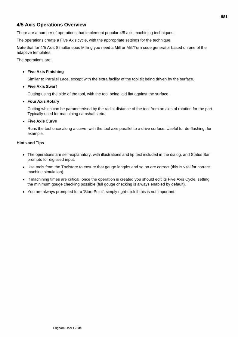
4/5 Axis Operations Overview
There are a number of operations that implement popular 4/5 axis machining techniques.
The operations create a Five Axis cycle, with the appropriate settings for the technique.
Note that for 4/5 Axis Simultaneous Milling you need a Mill or Mill/Turn code generator based on one of theadaptive templates.
The operations are:
Five Axis Finishing
Similar to Parallel Lace, except with the extra facility of the tool tilt being driven by the surface.
Five Axis Swarf
Cutting using the side of the tool, with the tool being laid flat against the surface.
Four Axis Rotary
Cutting which can be parameterised by the radial distance of the tool from an axis of rotation for the part.Typically used for machining camshafts etc.
Five Axis Curve
Runs the tool once along a curve, with the tool axis parallel to a drive surface. Useful for de-flashing, forexample.
Hints and Tips
The operations are self-explanatory, with illustrations and tip text included in the dialog, and Status Barprompts for digitised input.
Use tools from the Toolstore to ensure that gauge lengths and so on are correct (this is vital for correctmachine simulation).
If machining times are critical, once the operation is created you should edit its Five Axis Cycle, settingthe minimum gouge checking possible (full gouge checking is always enabled by default).
You are always prompted for a 'Start Point', simply right-click if this is not important.
881
Edgcam User Guide

Sequence of Instructions in 4/5 Axis Operations
The sequence is:
[Standard Sequence]
Five Axis Milling Cycle
882
Edgcam User Guide
What is Edgecam Turning?
The Edgecam Turning module allows you to use fixed tooling to generate toolpaths from turned geometry. Themodule permits both Two Axis and Four Axis Turning.
Fixed tool types of many styles can be used, and include:
Right, left, and neutral handed external turn
Right, neutral, and back boring internal turn
Grooving and parting tools
Threading
Drills
Taps
Standard Two Axis Cycles
Rough Turn Finish Turn Rough Groove
Finish Groove Move Rapid Move Feed
Move Relative Move Relative 2 Move Constrained
Thread Hole cycles (Fixed tool)
Standard Four Axis Cycles
Balanced Rough Turn Balanced Straight Turn
Mirror Rough Turn Mirror Straight Turn
In addition, any Two Axis cycle may be synchronised with another, provided that they are being performed onseparate turrets.
Driven Tools on a Turning Centre
Edgecam supports milling and drilling of 2D geometry on a turned part in three modes:
Axial Milling
Radial Milling
Y Axis Milling (Planar)
Swept Profiles
2D turned profiles may be swept to represent the turned component in three dimensions.
883
Edgcam User Guide

Solids Preferences
Use Options menu Preferences Solids tab to make preferences settings relating to solids.
(You can also access this help using the cycle dialog's Help button.)
884
Edgcam User Guide

Simulating the Chuck Grip
When creating a machining sequence, you can simulate the chuck's grip on the part using the Chuck Setuptab, as explained below.
(You can also access this help using the cycle dialog's Help button.)
885
Edgcam User Guide
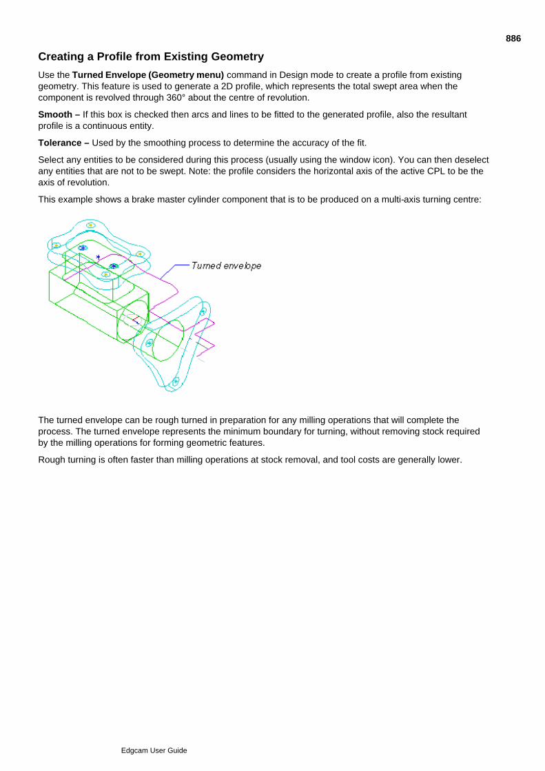
Creating a Profile from Existing Geometry
Use the Turned Envelope (Geometry menu) command in Design mode to create a profile from existinggeometry. This feature is used to generate a 2D profile, which represents the total swept area when thecomponent is revolved through 360° about the centre of revolution.
Smooth – If this box is checked then arcs and lines to be fitted to the generated profile, also the resultantprofile is a continuous entity.
Tolerance – Used by the smoothing process to determine the accuracy of the fit.
Select any entities to be considered during this process (usually using the window icon). You can then deselectany entities that are not to be swept. Note: the profile considers the horizontal axis of the active CPL to be theaxis of revolution.
This example shows a brake master cylinder component that is to be produced on a multi-axis turning centre:
The turned envelope can be rough turned in preparation for any milling operations that will complete theprocess. The turned envelope represents the minimum boundary for turning, without removing stock requiredby the milling operations for forming geometric features.
Rough turning is often faster than milling operations at stock removal, and tool costs are generally lower.
886
Edgcam User Guide

Sweeping the Component Graphics
Although you may have defined the profile geometry, you may want to get some idea of what the resultingturned part looks like.
Use the Design mode command Sweep (View menu) to draw repeats of the selected profile at regularintervals about the Z axis (or any other specified axis). These repeats and related geometry are called “sweptgraphics”.
These parameters are important in creating swept graphics:
End Angle – Specifies the angle at which the last repeat appears.
Repeats – Specifies the number of repeats to appear in a 360° rotation about the selected axis.
Circles – Check the box to create circles at the ends of the swept entities.
Views – Specifies the ports in which the swept graphics appear.
CPL – Specifies the axis (from all available CPLs) about which the profile is swept.
Example
887
Edgcam User Guide

Defining Billets
A billet represents the raw stock (casting, forging or previously machined component) to be machined into thepart.
Turn cycles that use stock include Rough Turn, Rough Groove and Rough Side Groove. The billet tells thecycle where cuts need to be made to remove material.
As with other types of stock, you can create billets with the Stock/Fixture command:
Click Geometry menu Stock/Fixture.1.
In the Stock dialog, make sure that Shape is set to Turn Billet.2.
When you come to digitise, you will be prompted for a 2D Profile to define the billet.3.
You can now digitise the billet profile when specifying cycle geometry. (Note that you need to digitise the endpoint of the profile.)
However you do not necessarily need pre-defined billets. At the 'Digitise billet or cycle start position' prompt,you could digitise:
An existing toolpath. The cycle then only removes the material left by the previous machining. See UsingDynamic Billeting for more information.
A turn feature. This would typically be derived from a separate solid model, representing the billet.
Note that for this digitise, you need to hold down the Ctrl key while clicking on the feature.
888
Edgcam User Guide
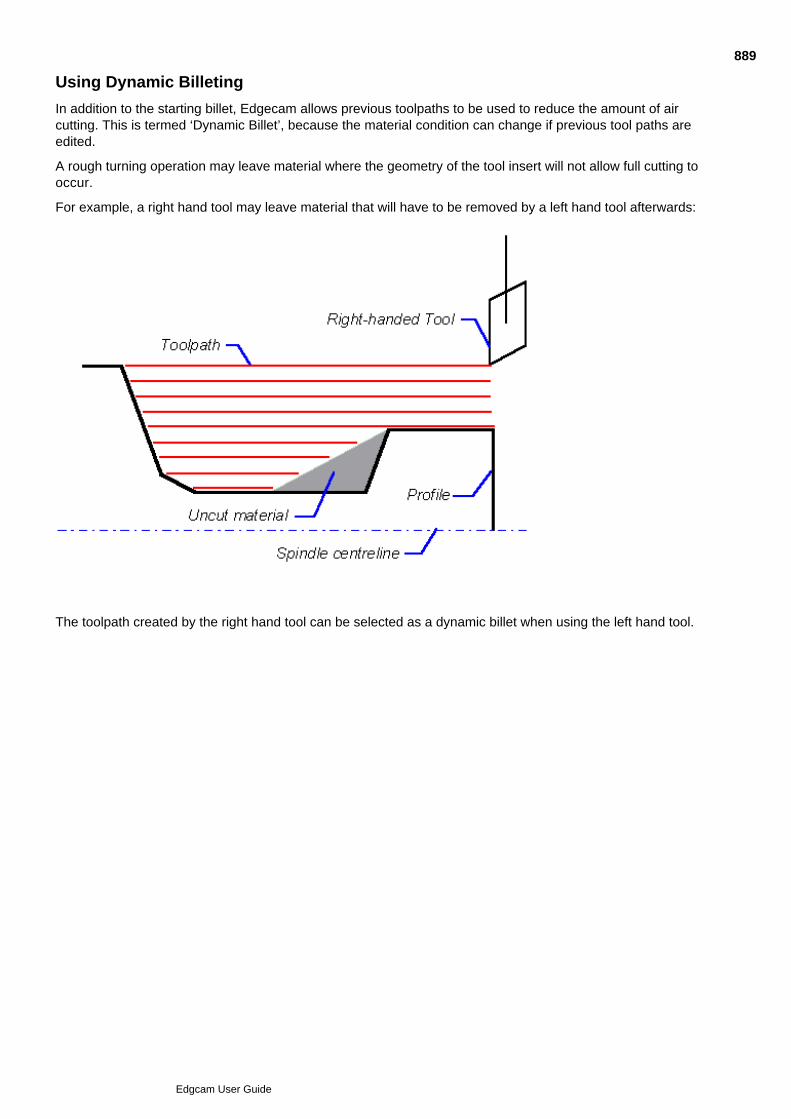
Using Dynamic Billeting
In addition to the starting billet, Edgecam allows previous toolpaths to be used to reduce the amount of aircutting. This is termed ‘Dynamic Billet’, because the material condition can change if previous tool paths areedited.
A rough turning operation may leave material where the geometry of the tool insert will not allow full cutting tooccur.
For example, a right hand tool may leave material that will have to be removed by a left hand tool afterwards:
The toolpath created by the right hand tool can be selected as a dynamic billet when using the left hand tool.
889
Edgcam User Guide
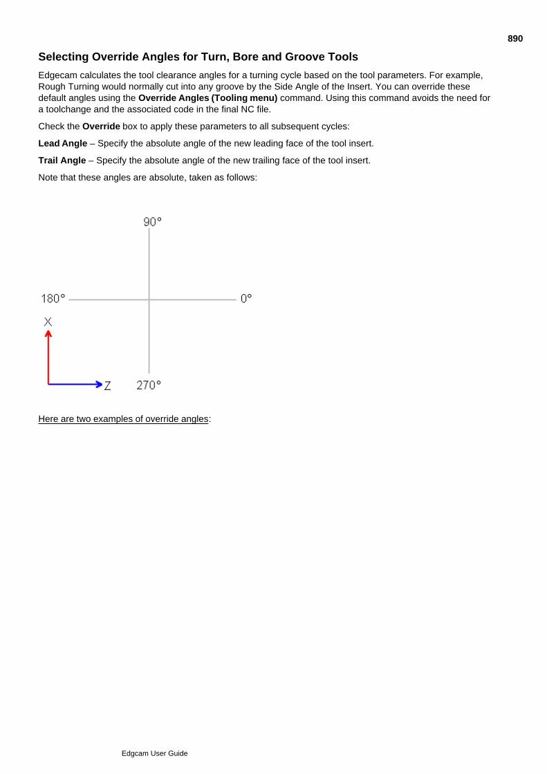
Selecting Override Angles for Turn, Bore and Groove Tools
Edgecam calculates the tool clearance angles for a turning cycle based on the tool parameters. For example,Rough Turning would normally cut into any groove by the Side Angle of the Insert. You can override thesedefault angles using the Override Angles (Tooling menu) command. Using this command avoids the need fora toolchange and the associated code in the final NC file.
Check the Override box to apply these parameters to all subsequent cycles:
Lead Angle – Specify the absolute angle of the new leading face of the tool insert.
Trail Angle – Specify the absolute angle of the new trailing face of the tool insert.
Note that these angles are absolute, taken as follows:
Here are two examples of override angles:
890
Edgcam User Guide

Orienting the Tool
When defining a new tool (from the Tooling menu or using the tool buttons), you need to specify the directionto hold the tool.
Click on the Turret... button in the toolchange parameter box and specify the:
Orientation – Aligns the tool with an axis of the Machine tool Co-ordinate System.
Axial – Orients the tool in the Z axis direction.
Radial – Orients the tool in the X axis direction.
Reverse Axial – Orients the tool in the negative Z axis direction.
891
Edgcam User Guide
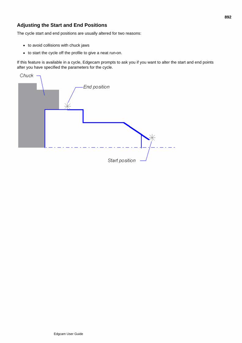
Adjusting the Start and End Positions
The cycle start and end positions are usually altered for two reasons:
to avoid collisions with chuck jaws
to start the cycle off the profile to give a neat run-on.
If this feature is available in a cycle, Edgecam prompts to ask you if you want to alter the start and end pointsafter you have specified the parameters for the cycle.
892
Edgcam User Guide
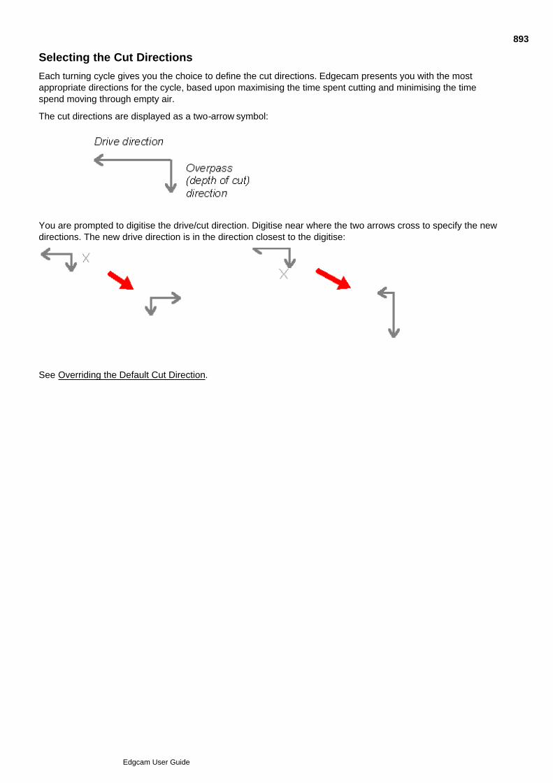
Selecting the Cut Directions
Each turning cycle gives you the choice to define the cut directions. Edgecam presents you with the mostappropriate directions for the cycle, based upon maximising the time spent cutting and minimising the timespend moving through empty air.
The cut directions are displayed as a two-arrow symbol:
You are prompted to digitise the drive/cut direction. Digitise near where the two arrows cross to specify the newdirections. The new drive direction is in the direction closest to the digitise:
See Overriding the Default Cut Direction.
893
Edgcam User Guide

Overriding the Default Cut Direction
Edgecam calculates the cut direction for a turning cycle based on the tool parameters and the materialboundary.
If you want to override these default directions, use the Cut Directions (Tooling menu) command.
Check the Override box to apply the Drive and Overpass angles to all subsequent cycles.
Drive – Specify an angle from 0° to 360°.
Overpass – Select from plus or minus 90°. This is incremental to the Drive angle, so that Drive and Overpassare always at right angles.
When you want to return to using the default cutting directions, select this command again but make sure thatthe Override box is clear.
894
Edgcam User Guide

Setting Spindle Control and Feed Types
To make spindle control settings, such as the Direction and Gear use:
M-Functions menu Spindle Control (adaptive code generators only)
Or if ths is not available (non-adaptive code generators) use various other M-Function commands, suchas M-Functions menu CSS.
Note that for adaptive code generators you can also use the Spindle tab in a Toolchange dialog. Use theSpindle Control command if you want to change the settings for the existing tool.
For more information click the Help button in the command's dialog.
895
Edgcam User Guide
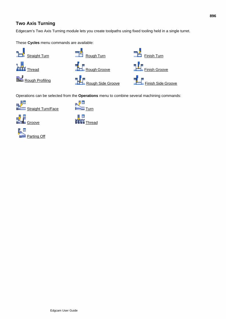
Two Axis Turning
Edgecam’s Two Axis Turning module lets you create toolpaths using fixed tooling held in a single turret.
These Cycles menu commands are available:
Straight Turn Rough Turn Finish Turn
Thread Rough Groove Finish Groove
Rough Profiling Rough Side Groove Finish Side Groove
Operations can be selected from the Operations menu to combine several machining commands:
Straight Turn/Face Turn
Groove Thread
Parting Off
896
Edgcam User Guide

Multiple Repetitive Stock Removal
This section describes the methods of removing material through sequential passes.
The usual procedure is to first face off the material, to make the part ready for roughing and finishing cycles. You can: Rough out material in a rectangular area
Rough out material down to a profile, using straight cuts
Rough our material down to a profile, using cuts parallel to the turn profile
See Also
Removing Spurs of Material on the Spindle Centreline
897
Edgcam User Guide
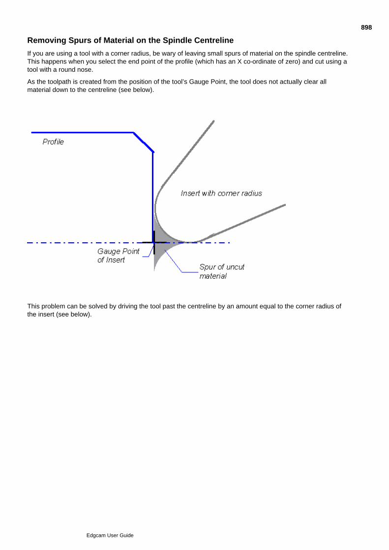
Removing Spurs of Material on the Spindle Centreline
If you are using a tool with a corner radius, be wary of leaving small spurs of material on the spindle centreline.This happens when you select the end point of the profile (which has an X co-ordinate of zero) and cut using atool with a round nose.
As the toolpath is created from the position of the tool’s Gauge Point, the tool does not actually clear allmaterial down to the centreline (see below).
This problem can be solved by driving the tool past the centreline by an amount equal to the corner radius ofthe insert (see below).
898
Edgcam User Guide
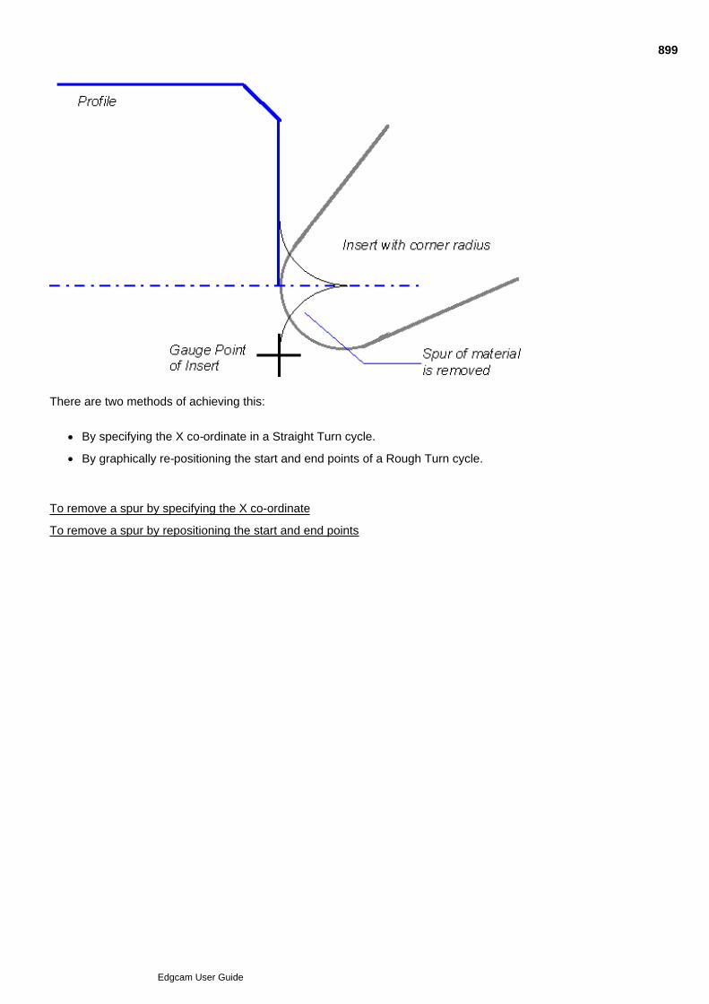
There are two methods of achieving this:
By specifying the X co-ordinate in a Straight Turn cycle.
By graphically re-positioning the start and end points of a Rough Turn cycle.
To remove a spur by specifying the X co-ordinate
To remove a spur by repositioning the start and end points
899
Edgcam User Guide

Straight Turn Cycle
Use Turn Cycles menu Straight Turn to make multiple straight cuts within a specifiedrectangular area. You could use the cycle to face off, for example.
Here are details on the settings in the cycle dialog (you can also access this help by clicking the Help button inthe dialog):
900
Edgcam User Guide

Rough Profile Cycle
Use Turn Cycles menu Rough Profile to remove material by making a series of cuts parallelto the profile.
Here are details on the settings in the cycle dialog (you can also access this help by clicking the Help button inthe dialog):
901
Edgcam User Guide

Roughing Turn Parts
Use Turn Cycles menu New Rough Turn to remove material down to a profile.
Here are details on the settings in the cycle dialog (you can also access this help by clicking the Help button inthe dialog):
902
Edgcam User Guide

Roughing Turn Parts
Use Turn Cycles menu Rough Turn to remove material down to a profile.
Here are details on the settings in the cycle dialog (you can also access this help by clicking the Help button inthe dialog):
903
Edgcam User Guide

Rough Turn Dialog General tab
In the General tab of the Rough Turn cycle you make general settings such as the feeds and speeds:
904
Edgcam User Guide

Rough Turn dialog Cycle Control tab
In the Cycle Control tab of the Rough Turn cycle you mainly control the Approach and Retract moves:
905
Edgcam User Guide

Roughing Turn Parts
In the Advanced tab of the Rough Turn cycle you make advanced settings, such as the Corner Type and theTolerance:
906
Edgcam User Guide
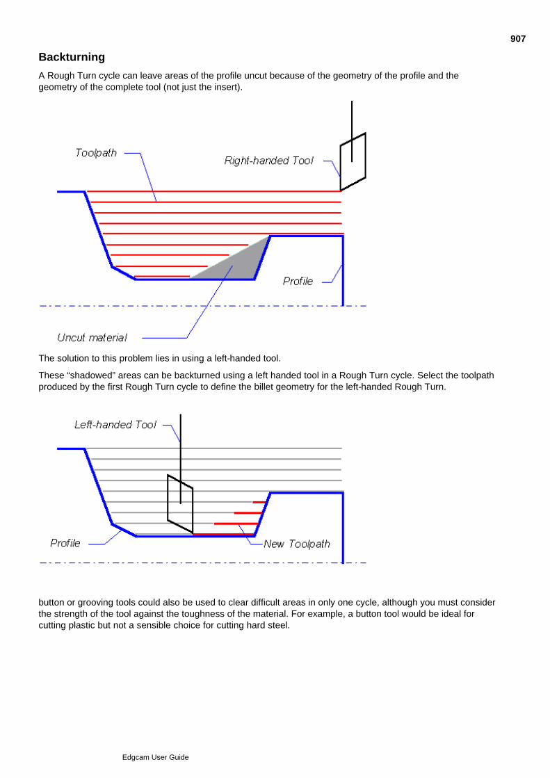
Backturning
A Rough Turn cycle can leave areas of the profile uncut because of the geometry of the profile and thegeometry of the complete tool (not just the insert).
The solution to this problem lies in using a left-handed tool.
These “shadowed” areas can be backturned using a left handed tool in a Rough Turn cycle. Select the toolpathproduced by the first Rough Turn cycle to define the billet geometry for the left-handed Rough Turn.
button or grooving tools could also be used to clear difficult areas in only one cycle, although you must considerthe strength of the tool against the toughness of the material. For example, a button tool would be ideal forcutting plastic but not a sensible choice for cutting hard steel.
907
Edgcam User Guide

Making Finishing Passes
To make a finishing pass:
We recommend you use the Finish Turn (Turn Cycles menu) cycle only if you need canned cyclesupport...
Otherwise we recommend you use the later Finish Turning cycle Finish Turning Cycle.
You can also use:
Relative (Move menu)
Constrained (Move menu)
Relative 2 (Move menu)
908
Edgcam User Guide

Using Finish Turn
Use the Finish Turn cycle to run the tool once along the profile.
(We recommend you use the later New Finish Turning Cycle unless you need canned cycle support.)
The cycle uses standard parameters apart from these:
909
Edgcam User Guide

Finish Turn Dialog General tab
In the General tab of the Finish Turn Cycle you make general settings such as the feeds and speeds.
Here are details on the tab's settings (you can also access this help by clicking the Help button in the dialog):
910
Edgcam User Guide

Finish Turn Dialog Leads tab
In the Leads tab of the Finish Turn Cycle you make settings that control the Lead In/Out moves.
Here are details on the tab's settings (you can also access this help by clicking the Help button in the dialog):
911
Edgcam User Guide

Finish Turn Dialog Advanced tab
In the Advanced tab of the Finish Turn Cycle you make advanced settings such as the tolerance and cornercontrol.
Here are details on the tab's settings (you can also access this help by clicking the Help button in the dialog):
912
Edgcam User Guide

New Finish Turn Cycle
Use Turn Cycles New Finish Turn Cycle to run the tool once along the profile.
(We recommend you use the earlier Finish Turn Cycle if you need canned cycle support.)
Here are details on the using the cycle and the cycle dialog's settings (you can also access this help by clickingthe Help button in the dialog):
913
Edgcam User Guide

New Finish Turn Dialog General tab
In the General tab of the New Finish Turn Cycle you make general settings such as the feeds and speeds (youcan vary these for individual parts of the profile), and the Cutter Compensation scheme to be used.
Here are details on the tab's settings (you can also access this help by clicking the Help button in the dialog):
914
Edgcam User Guide

New Finish Turn Dialog Leads/Links tab
In the Leads/Links tab of the New Finish Turn Cycle you make settings that control Leads and Links.
Here are details on the tab's settings (you can also access this help by clicking the Help button in the dialog):
915
Edgcam User Guide

New Finish Turn Dialog Control tab
In the Control tab of the New Finish Turn Cycle you make settings for upcut/downcut and corner control.
Here are details on the tab's settings (you can also access this help by clicking the Help button in the dialog):
916
Edgcam User Guide

Thread Cycle
Use Turn Cycles menu Thread to turn internal or external threads.
Here are details on the settings in the cycle dialog (you can also access this help by clicking the Help button inthe dialog):
917
Edgcam User Guide

Grooving
To cut a groove with fixed tooling you can:
'Form' the groove using the tool shape, using Move menu commands.
'Generate' the groove, where the groove does not match the tool shape.
To generate the groove you first rough the groove. You can use the Rough Groove cycle to cut using theend of the tool (plunging the tool along its axis) or the Rough Side Groove cycle to cut with the side of thetool (move the tool sideways). (You could also use the Rough Turn cycle)
You then finish the groove using use the Finish Groove or Finish Side Groove cycle (or perhaps theFinish Turn cycle).
You can also make grooves using driven tooling in Rotary mode. For more details, see Milling in Rotary Mode.
918
Edgcam User Guide
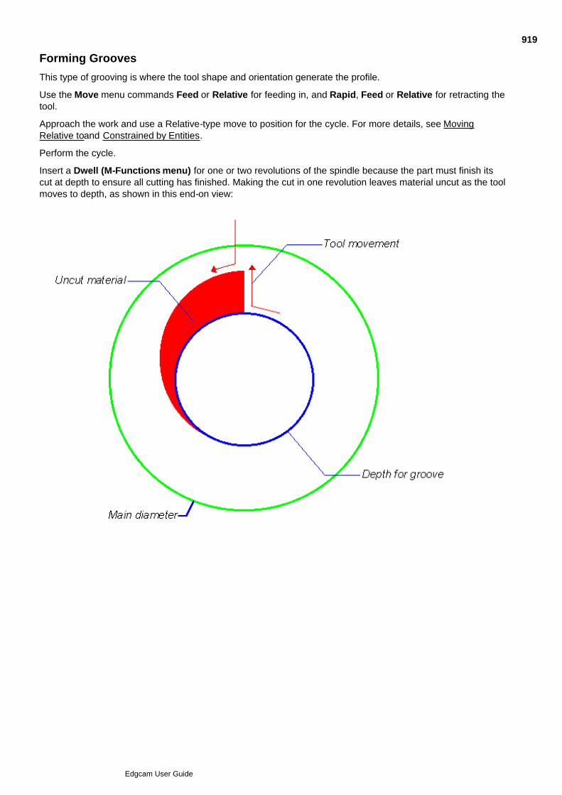
Forming Grooves
This type of grooving is where the tool shape and orientation generate the profile.
Use the Move menu commands Feed or Relative for feeding in, and Rapid, Feed or Relative for retracting thetool.
Approach the work and use a Relative-type move to position for the cycle. For more details, see MovingRelative toand Constrained by Entities.
Perform the cycle.
Insert a Dwell (M-Functions menu) for one or two revolutions of the spindle because the part must finish itscut at depth to ensure all cutting has finished. Making the cut in one revolution leaves material uncut as the toolmoves to depth, as shown in this end-on view:
919
Edgcam User Guide
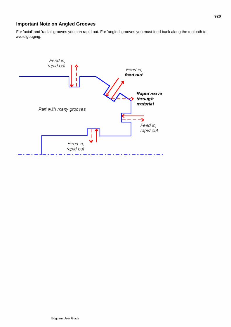
Important Note on Angled Grooves
For 'axial' and 'radial' grooves you can rapid out. For 'angled' grooves you must feed back along the toolpath toavoid gouging.
920
Edgcam User Guide

Rough Groove Cycle
Use Turn cycles Rough Groove to remove the bulk of the material from the groove. Use the 'X andZ Offsets' to leave material for the Finish Groove cycle.
So that the cycle knows where to cut to remove material, you specify a 'billet'.
Here are details on the using the cycle and the cycle dialog's settings (you can also access this help by clickingthe Help button in the dialog):
921
Edgcam User Guide

Rough Groove Dialog General tab
In the General tab of the Rough Groove cycle you make general settings such as the speeds and offsets.
Here are details on the tab's settings (you can also access this help by clicking the Help button in the dialog):
922
Edgcam User Guide

Rough Groove Dialog Advanced tab
In the Advanced tab of the Rough Groove cycle you make advanced settings such as the tolerance and cornercontrol.
Here are details on the tab's settings (you can also access this help by clicking the Help button in the dialog):
923
Edgcam User Guide

Rough Side Groove Cycle
Use Turn cycles Rough Side Groove to remove the bulk of the material from the groove. Use the 'Xand Z Offsets' to leave material for the Finish Groove cycle.
So that the cycle knows where to cut to remove material, you specify a 'billet'.
Here are details on the using the cycle and the cycle dialog's settings (you can also access this help by clickingthe Help button in the dialog):
924
Edgcam User Guide

Rough Side Groove Dialog General tab
In the General tab of the Rough Groove cycle you make general settings such as the speeds and offsets.
Here are details on the tab's settings (you can also access this help by clicking the Help button in the dialog):
925
Edgcam User Guide

Rough Side Groove Dialog Advanced tab
In the Advanced tab of the Rough Groove cycle you make advanced settings such as the tolerance and cornercontrol.
Here are details on the tab's settings (you can also access this help by clicking the Help button in the dialog):
926
Edgcam User Guide

Finish Groove Cycle
Use Turn cycles Finish Groove to run the tool along the groove profile.
Here are details on the using the cycle and the cycle dialog's settings (you can also access this help by clickingthe Help button in the dialog):
927
Edgcam User Guide

Finish Groove Dialog General tab
In the General tab of the Finish Groove cycle you make general settings such as the speeds and offsets.
Here are details on the tab's settings (you can also access this help by clicking the Help button in the dialog):
928
Edgcam User Guide

Finish Groove Dialog Advanced tab
In the Advanced tab of the Finish Groove cycle you make advanced settings such as the tolerance and cornercontrol.
Here are details on the tab's settings (you can also access this help by clicking the Help button in the dialog):
929
Edgcam User Guide

Finish Side Groove Cycle
Use Turn cycles Finish Side Groove to run the tool along the groove profile.
Here are details on the using the cycle and the cycle dialog's settings (you can also access this help by clickingthe Help button in the dialog):
930
Edgcam User Guide

Finish Side Groove Dialog General tab
In the General tab of the Finish Side Groove cycle you make general settings such as the speeds and offsets.
Here are details on the tab's settings (you can also access this help by clicking the Help button in the dialog):
931
Edgcam User Guide

Finish Side Groove Dialog Advanced tab
In the Advanced tab of the Finish Side Groove cycle you make advanced settings such as the tolerance andcorner control.
Here are details on the tab's settings (you can also access this help by clicking the Help button in the dialog):
932
Edgcam User Guide

Special Conditions in Grooving
When the groove pocket is defined by a large arc, a transition may occur between the concept of a wall and theconcept of a floor. In such a case, the arc is considered as two separate elements, a wall from vertical to 46°and a floor from 44° to the horizontal. When approaching the transition point, an arcing move of arc radius/4will be made. This will be from the vertical for wall approaches, and from the horizontal for floor approaches.
When changing from a Plunge to a Side move, the tool is driven at 25% of the Side Feedrate for twicethe Side Force Correction distance (or at least 0.1mm/0.01in) to allow the tool to deflect.
933
Edgcam User Guide

Specifying the Distance Between Cuts
Use only ONE of these parameters to define this distance:
Cut Increment
Stepover
This will then be modified by default (see No Stepover Adjustment below).
Cut Increment – Specify the distance between cuts in the units used for the part.
Stepover – Specify the distance between cuts as a percentage of the effective length of the cutting edge of thetool.No Stepover Adjustment – Once the cut increment has been defined, by default Edgecam ensures that asmall cut is not made on the last pass by averaging the cut distance between all the passes. To stop Edgecamfrom averaging the cuts, check the No Stepover Adjustment box.
The distance between cuts can also be modified by this parameter:
Degression – (Roughing) Specify the amount by which to reduce each consecutive cut increment. The cutincrement eventually equals the Degression value, and cannot be reduced any further.
This would be used on long shaft parts where the rigidity of the component reduces as the stock is removed.
934
Edgcam User Guide
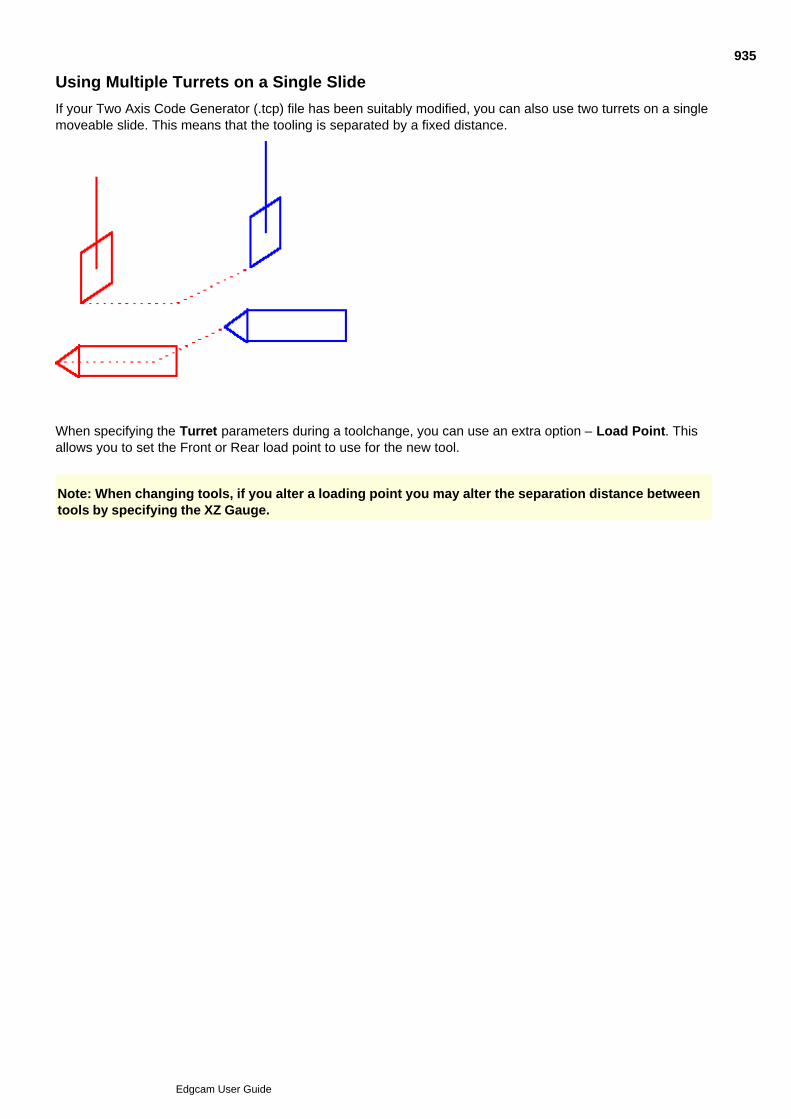
Using Multiple Turrets on a Single Slide
If your Two Axis Code Generator (.tcp) file has been suitably modified, you can also use two turrets on a singlemoveable slide. This means that the tooling is separated by a fixed distance.
When specifying the Turret parameters during a toolchange, you can use an extra option – Load Point. Thisallows you to set the Front or Rear load point to use for the new tool.
Note: When changing tools, if you alter a loading point you may alter the separation distance betweentools by specifying the XZ Gauge.
935
Edgcam User Guide
Operational Programming in Turning
Operations are collections of individual machining cycles and commands. By gathering a series of instructionsunder one command, the number of mouse clicks and key presses you have to make to obtain results is greatlyreduced.
If you have not already defined a machining sequence, you will be prompted to do so when you select amachining command or operation.
Once you have selected an operation, you will be asked to digitise entities and locations to provide data for theoperation. A dialog box is then presented so you can enter values and selections to control the operation. Notethat this is the opposite of how an individual Edgecam cycle works, where the entity and other data from thescreen is entered after the dialog for the cycle.
Edgecam uses the defined strategy for the operation plus all other data input to produce a series of machininginstructions. Typically, the instructions include a move-to-toolchange, tool selection, approach moves,compensation (where applicable), and one or more turning cycles.
Note that you do not have to use Operations – they simply provide a way of performing a series of instructionswithin a single command. Rather than use Operations, you may still select each machining instructionindividually.
Apart from the manufacturing operations, you can use these important commands:
Preferences allows you to specify a range of preferred values that will apply to all subsequent machiningcycles and operations. See Specifying Preferences for Turning Operations for details. Note that you mustinitialise a machining sequence for this command to work.
Batch Mode lets you delay toolpath processing for one or more operations by batching them andperforming the processing at a more useful time, for example at the end of the worksession. For details seeUsing Batch Mode for Operations.
Index allows you to perform an incremental or absolute datum shift to a specified angle or a selecteddatum. See Index Operation.
For information about using the ToolStore in Operations, please see Operational Programming in Milling.
See Also
Selecting a Turning Operation
Using Batch Mode for Operations
936
Edgcam User Guide

Selecting a Turning Operation
These operations are available under the Operations menu:
Straight Turn/Face Turn Parting Off
Groove Thread Hole
See Also
Specifying Preferences for Turning Operations
Standard Sequence for Turning Operations
Using Batch Mode for Operations
Index Operation
937
Edgcam User Guide

Specifying Preferences for Turning Operations
The Preferences (Operations menu) command allows you to specify a range of preferred values that willapply to all subsequent machining cycles and operations.
You must have initialised a machining sequence or this command will not work.
938
Edgcam User Guide
Standard Sequence for Turning Operations
These are the machining instructions performed as standard for each operation:
Coolant Off – (If selected in Preferences)
Spindle Stop – (If selected in Preferences)
Rapid to Toolchange
Toolchange
Coolant – (From Preferences)
None of these instructions will be performed if the current tool is ‘identical’ to the tool definition for theoperation. A turning tool is considered to be identical if the turret position, tool type, corner/nose radius and thefollowing modifiers are the same:
Tool Type Modifiers
Groove Tool Width
Thread Tool Included Angle
Turn/Bore Tool Symbol/Included Angle, EdgeLength/Inscribed Circle, andSide/End Angle
939
Edgcam User Guide
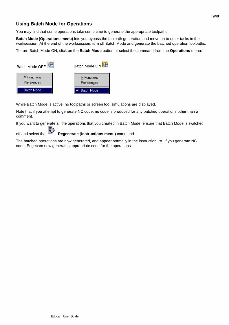
Using Batch Mode for Operations
You may find that some operations take some time to generate the appropriate toolpaths.
Batch Mode (Operations menu) lets you bypass the toolpath generation and move on to other tasks in theworksession. At the end of the worksession, turn off Batch Mode and generate the batched operation toolpaths.
To turn Batch Mode ON, click on the Batch Mode button or select the command from the Operations menu:
Batch Mode OFF Batch Mode ON
While Batch Mode is active, no toolpaths or screen tool simulations are displayed.
Note that if you attempt to generate NC code, no code is produced for any batched operations other than acomment.
If you want to generate all the operations that you created in Batch Mode, ensure that Batch Mode is switched
off and select the Regenerate (Instructions menu) command.
The batched operations are now generated, and appear normally in the instruction list. If you generate NCcode, Edgecam now generates appropriate code for the operations.
940
Edgcam User Guide

Index Operation
The Index (Operations menu) command allows you to perform an incremental or absolute datum shiftto a specified angle or a selected datum.
See also
Sequence of Instructions in the Index Operation
Using the Index Operation
941
Edgcam User Guide

Sequence of Instructions in the Index Operation
Index
Move Rapid to the specified Clearance value
Move Index to either the specified angle or datum
942
Edgcam User Guide

Using the Index Operation
Click on the Index Operation The tool is now indexed.1.
943
Edgcam User Guide

Straight Turn/Face Operation
The Straight Turn/Face (Operations menu) command can be used to perform multiple commandswithin a single instruction.
Sequence of Instructions in the Straight Turn/Face Operation
Using the Straight Turn/Face Operation
Straight Turn/Face Operation Parameters
944
Edgcam User Guide

Sequence of Instructions in the Straight Turn/Face Operation
Straight Turn/Face
[Standard Sequence]
CSS
Straight Turn Cycle
See the Standard Sequence for Turning Operations for details of the Standard Sequence.
945
Edgcam User Guide

Using the Straight Turn/Face Operation
Click on the Straight Turn/Face Operation button.1.
Digitise a start point for the cycle.2.
Digitise the destination point for the cycle.3.
Complete the dialog box for the operation and click OK.4.
Edgecam now generates the toolpaths for the straight turn/face operation, including any moves to position thetool.
946
Edgcam User Guide
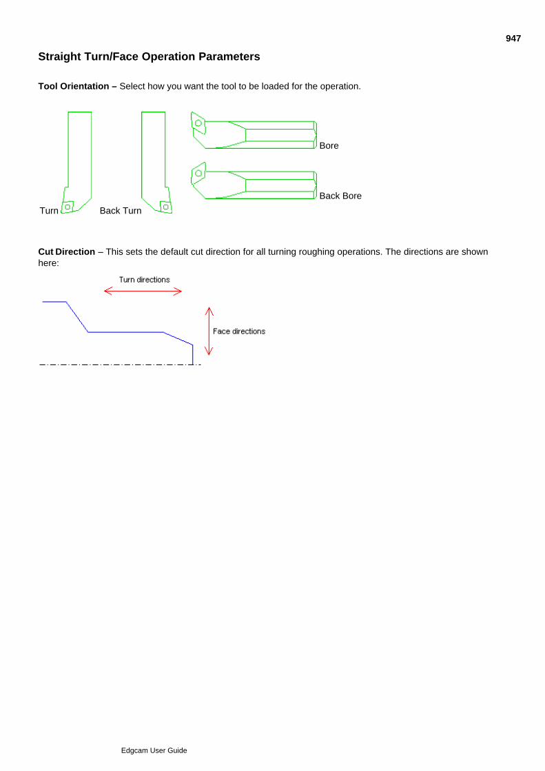
Straight Turn/Face Operation Parameters
Tool Orientation – Select how you want the tool to be loaded for the operation.
Turn Back Turn
Bore
Back Bore
Cut Direction – This sets the default cut direction for all turning roughing operations. The directions are shownhere:
947
Edgcam User Guide

Turn Operation
The Turn (Operations menu) command can be used to perform multiple commands within a singleinstruction.
Sequence of Instructions in the Turn Operation
Using the Turn Operation
Turn Operation General Parameters
Turn Operation Finishing Parameters
948
Edgcam User Guide

Sequence of Instructions in the Turn Operation
Roughing
[Standard Sequence]
CSS
Rough Turn Cycle
Finishing
[Standard Sequence]
CSS
Compensation On
Finish Turn Cycle
Compensation Off
See the Standard Sequence for Turning Operations for details of the Standard Sequence.
949
Edgcam User Guide

Using the Turn Operation
Click on the Turn Operation button.1.
Digitise the profile to be turned and then perform a Finish.2.
Digitise the new start point for the active profile (if necessary). Press the Ctrl key while holding down theleft mouse button to toggle between selecting a new start point and a new end point for the profile.
3.
Perform a Finish.4.
Digitise the cycle start point.5.
Digitise a toolpath or a continuous entity to act as a billet for the cycle (if necessary).6.
Perform a Finish to complete the billet selection.7.
Complete the dialog box for the operation and click OK.8.
Perform a Finish.9.
Edgecam now generates the toolpaths for the turn operation, including any moves to position the tool.
950
Edgcam User Guide
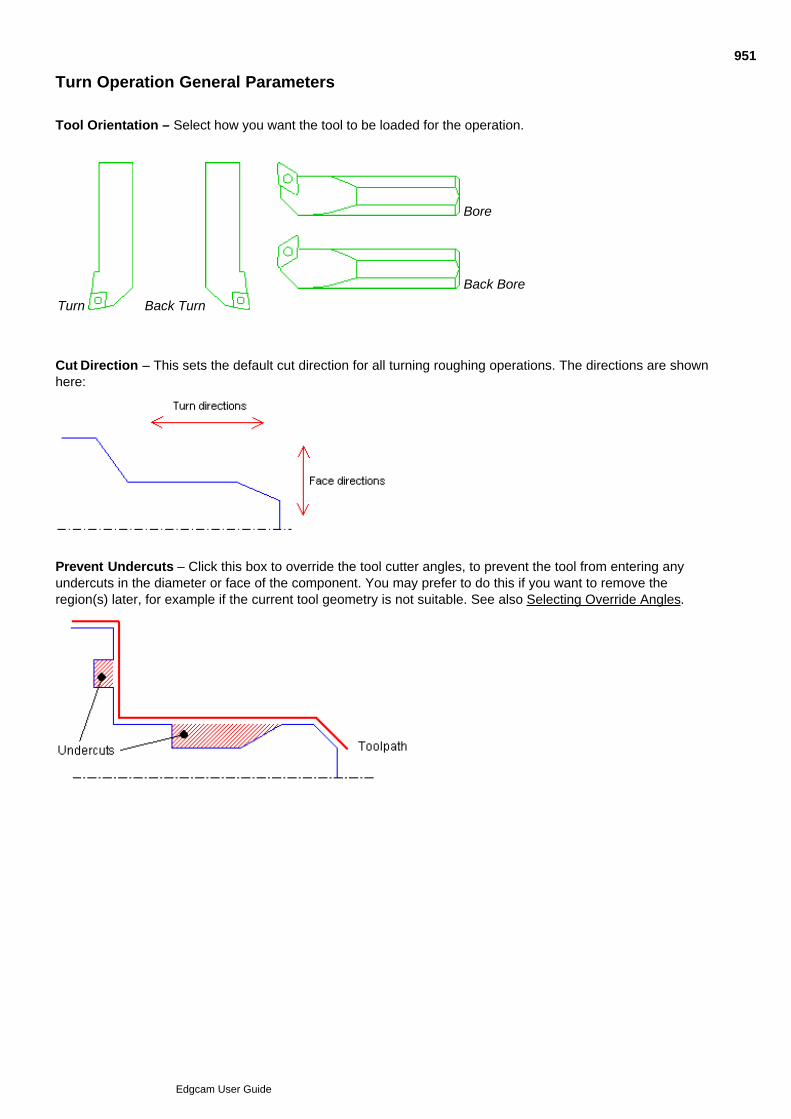
Turn Operation General Parameters
Tool Orientation – Select how you want the tool to be loaded for the operation.
Turn Back Turn
Bore
Back Bore
Cut Direction – This sets the default cut direction for all turning roughing operations. The directions are shownhere:
Prevent Undercuts – Click this box to override the tool cutter angles, to prevent the tool from entering anyundercuts in the diameter or face of the component. You may prefer to do this if you want to remove theregion(s) later, for example if the current tool geometry is not suitable. See also Selecting Override Angles.
951
Edgcam User Guide
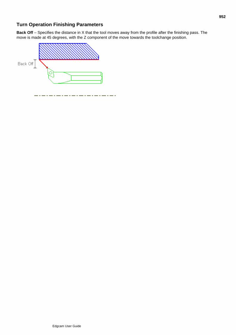
Turn Operation Finishing Parameters
Back Off – Specifies the distance in X that the tool moves away from the profile after the finishing pass. Themove is made at 45 degrees, with the Z component of the move towards the toolchange position.
952
Edgcam User Guide

Groove Operation
The Groove (Operations menu) command can be used to perform multiple commands within a singleinstruction.
Sequence of Instructions in the Groove Operation
Using the Groove Operation
Groove Operation Tool Type
953
Edgcam User Guide

Sequence of Instructions in the Groove Operation
Roughing
[Standard Sequence]
CSS
Rough Groove Cycle
Finishing
[Standard Sequence]
Cutter Comp = Pathcomp
CSS
Finish Groove Cycle
Cutter Comp = None
See the Standard Sequence for Turning Operations for details of the Standard Sequence.
954
Edgcam User Guide

Using the Groove Operation
Click on the Groove Operation button.1.
Digitise the profile to be grooved.2.
Perform a Finish to complete digitising the profile.3.
Digitise the new start point for the active profile (if necessary). Hold down the Ctrl key while selecting theleft mouse button to toggle between selecting a new start point and a new end point for the profile.
4.
Perform a Finish to complete digitising the new start point.5.
Digitise the cycle start point.6.
Complete the dialog box for the operation.7.
Click on OK.8.
Edgecam now generates the toolpaths for the groove operation, including any moves to position the tool.
955
Edgcam User Guide
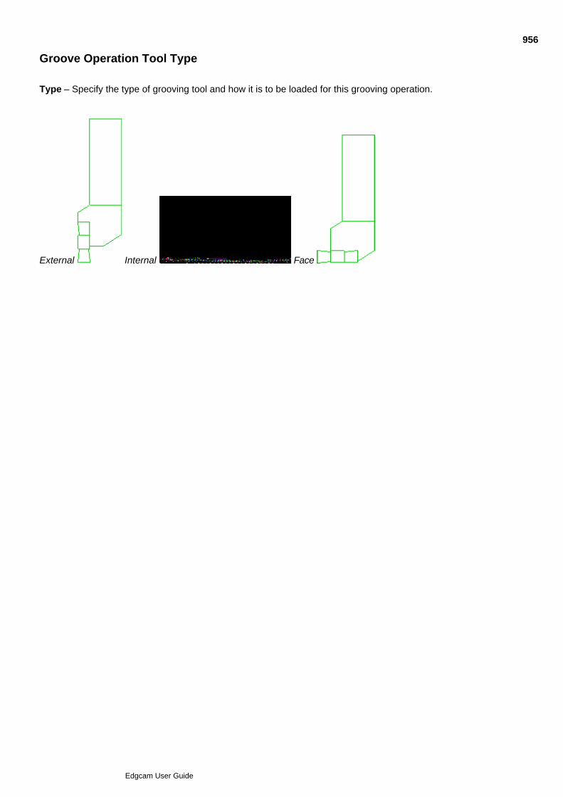
Groove Operation Tool Type
Type – Specify the type of grooving tool and how it is to be loaded for this grooving operation.
External Internal Face
956
Edgcam User Guide

Thread Operation
The Thread (Operations menu) command can be used to perform multiple commands within a singleinstruction.
Using the thread operation on a turn feature
When clicking on a feature to select it for the threading operation, the feature entity will be threaded if itcontains a single line as the profile (e.g. a manual feature was created by picking an aligned cylinder or cone).
We recommend that manual turn features be used for turn threading associativity. Manual turn features willhave a consistent direction based on material side. If necessary, the direction of the cycle can be reversed inthe Edit command by using the Reverse Material check box (this will be remembered on a solid reload).
Sequence of Instructions in the Thread Operation
Using the Thread Operation
Thread Operation Tool Type
957
Edgcam User Guide

Sequence of Instructions in the Thread Operation
Threading
[Standard Sequence]
CSS Off
Thread Cycle
See the Standard Sequence for Turning Operations for details of the Standard Sequence.
958
Edgcam User Guide

Using the Thread Operation
Click on the Thread Operation button.1.
Digitise the line to be threaded. The operation will start at the end of the line closest to your digitise.2.
Complete the dialog box for the operation.3.
Click OK.4.
Edgecam now generates the toolpaths for the thread operation, including any moves to position the tool.
959
Edgcam User Guide
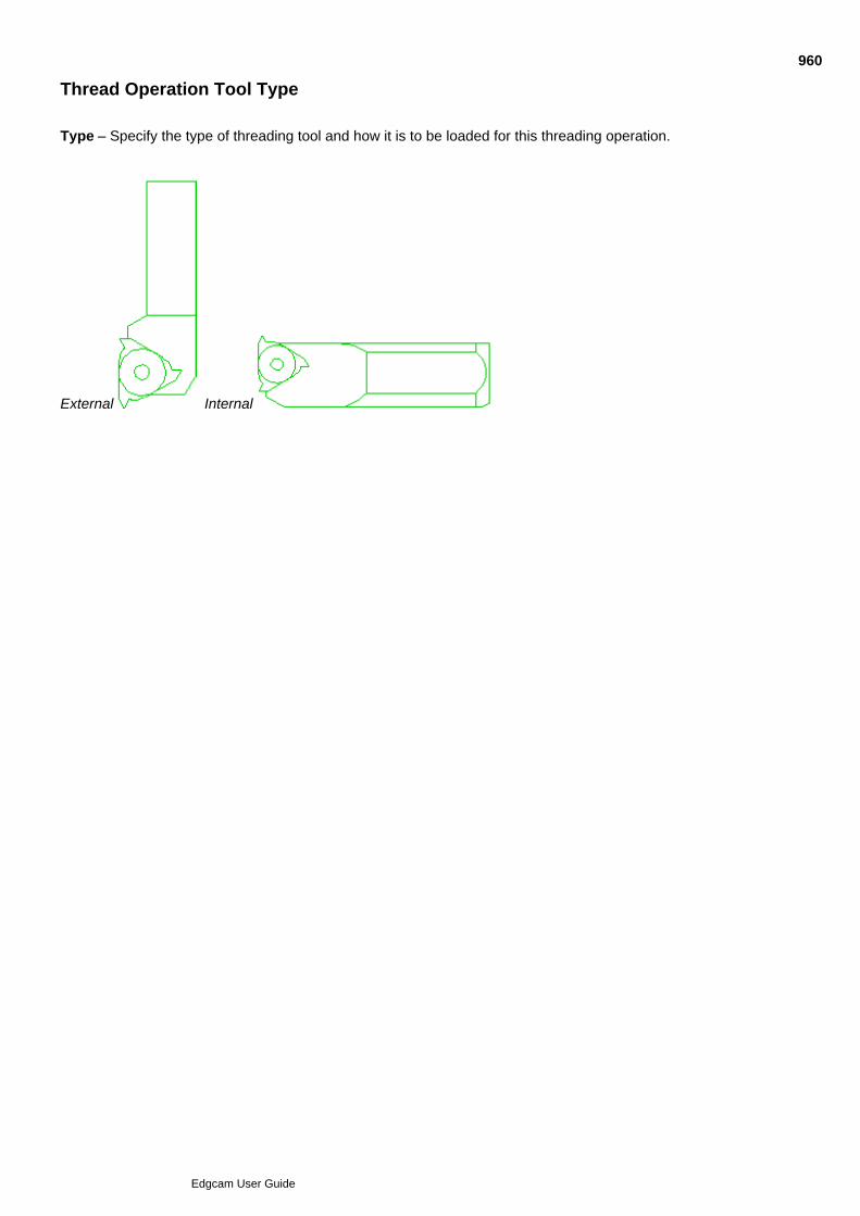
Thread Operation Tool Type
Type – Specify the type of threading tool and how it is to be loaded for this threading operation.
External Internal
960
Edgcam User Guide

Parting Off Operation
Parting Off (Operations menu) can be used to perform multiple commands within a singleinstruction.
Sequence of Instructions in the Parting Off Operation
Using the Parting Off Operation
Parting Off Operation Parameters
961
Edgcam User Guide

Sequence of Instructions in the Parting Off Operation
Parting Off
[Standard Sequence]
CSS Off
Parting Off Cycle
See the Standard Sequence for Turning Operations for details of the Standard Sequence.
962
Edgcam User Guide

Using the Parting Off Operation
Click on the Parting Off Operation button.1.
Digitise a line for the part off location.2.
Complete the dialog box for the operation.3.
Click OK.4.
Edgecam now generates the toolpaths for the parting off operation, including any moves to position the tool.
963
Edgcam User Guide
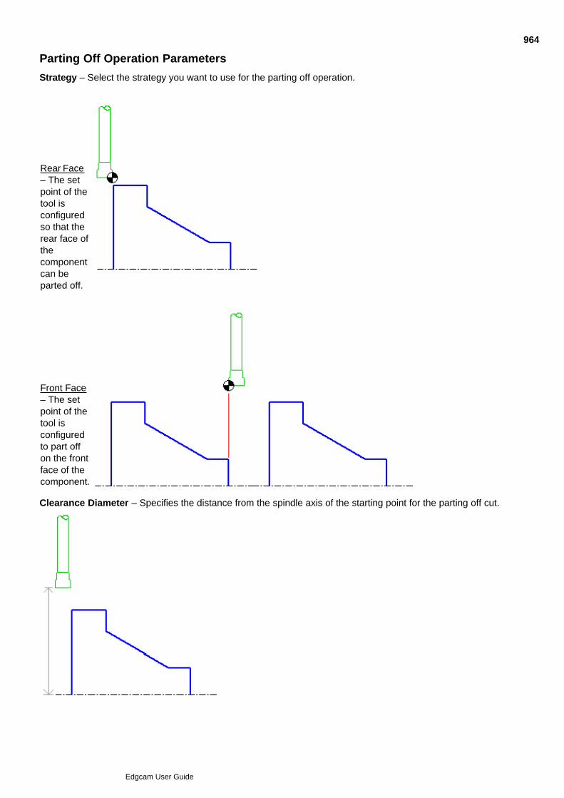
Parting Off Operation Parameters
Strategy – Select the strategy you want to use for the parting off operation.
Rear Face– The setpoint of thetool isconfiguredso that therear face ofthecomponentcan beparted off.
Front Face– The setpoint of thetool isconfiguredto part offon the frontface of thecomponent.
Clearance Diameter – Specifies the distance from the spindle axis of the starting point for the parting off cut.
964
Edgcam User Guide
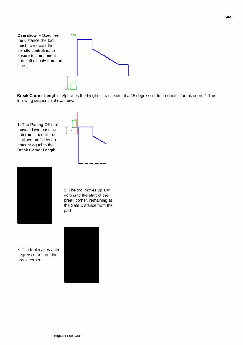
Overshoot – Specifiesthe distance the toolmust travel past thespindle centreline, toensure to componentparts off cleanly from thestock.
Break Corner Length – Specifies the length of each side of a 45 degree cut to produce a ‘break corner’. Thefollowing sequence shows how:
1. The Parting Off toolmoves down past theoutermost part of thedigitised profile by anamount equal to theBreak Corner Length.
2. The tool moves up andacross to the start of thebreak corner, remaining atthe Safe Distance from thepart.
3. The tool makes a 45degree cut to form thebreak corner.
965
Edgcam User Guide

4. The tool feeds down tofinish the parting off cut.
966
Edgcam User Guide

Hole Operation in Turning
The Hole (Operations menu) command allows you to combine several related drilling commands in oneinstruction.
See Also
Sequence of Instructions in the Turning Hole Operation
Using the Turning Hole Operation
Turning Hole Operation Termination
Turning Hole Operation Preparation Strategy
Turning Hole Operation Roughing Depth
967
Edgcam User Guide

Sequence of Instructions in the Turning Hole Operation
Centre/Spot
[Standard Sequence]
Drill Cycle
Preparation*
[Standard Sequence]
Drill Cycle
Roughing
[Standard Sequence]
Drill Cycle
Finishing
[Standard Sequence]
M-Functions – Spindle (If Strategy = Tap – Direction derived by hand)
Drill/Bore/Tap Cycle
*Note that Preparation could occur after Roughing if you check the Preparation tab’s After Roughing box.
See the Standard Sequence for Turning Operations for details of the Standard Sequence.
968
Edgcam User Guide

Using the Turning Hole Operation
Click on the Hole Operation button.1.
Complete the dialog box for the operation.2.
Click OK.3.
Edgecam now generates the toolpaths for the hole operation, including any moves to position the tool.
Note on using the Hole operation with solid parts
When using the Hole operation on a solid part with a tool selected from the ToolStore and the solid is updatedwith a different hole diameter, the tool will not be updated. A warning message is displayed giving the name ofthe tool and specifying that the ToolStore tool diameter and hole diameter do not match.
969
Edgcam User Guide
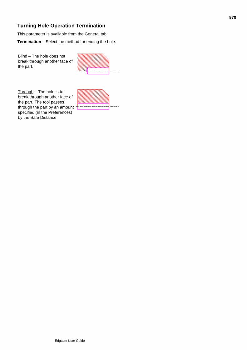
Turning Hole Operation Termination
This parameter is available from the General tab:
Termination – Select the method for ending the hole:
Blind – The hole does notbreak through another face ofthe part.
Through – The hole is tobreak through another face ofthe part. The tool passesthrough the part by an amountspecified (in the Preferences)by the Safe Distance.
970
Edgcam User Guide
Turning Hole Operation Preparation Strategy
Strategy – Select the preparation strategy you want to use for the hole operation.
No Preparation – Here is a hole featurewith no preparation:
Countersink – Specifies a taperedpreparation hole. Countersink has anincluded angle of 45 degrees. You canonly define the countersink using eitherDepth or Diameter. Here is a hole featureprepared with a countersink:
Counterbore – Specifies a fixeddiameter preparation hole. Here is a holefeature prepared with a counterbore:
971
Edgcam User Guide

Turning Hole Operation Roughing Depth
Depth (Full Diameter) –Specifies the depth of thehole, where the diameter ofthe hole remains constant.
972
Edgcam User Guide
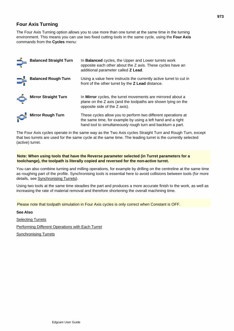
Four Axis Turning
The Four Axis Turning option allows you to use more than one turret at the same time in the turningenvironment. This means you can use two fixed cutting tools in the same cycle, using the Four Axiscommands from the Cycles menu:
Balanced Straight Turn In Balanced cycles, the Upper and Lower turrets workopposite each other about the Z axis. These cycles have anadditional parameter called Z Lead.
Balanced Rough Turn Using a value here instructs the currently active turret to cut infront of the other turret by the Z Lead distance.
Mirror Straight Turn In Mirror cycles, the turret movements are mirrored about aplane on the Z axis (and the toolpaths are shown lying on theopposite side of the Z axis).
Mirror Rough Turn These cycles allow you to perform two different operations atthe same time, for example by using a left hand and a righthand tool to simultaneously rough turn and backturn a part.
The Four Axis cycles operate in the same way as the Two Axis cycles Straight Turn and Rough Turn, exceptthat two turrets are used for the same cycle at the same time. The leading turret is the currently selected(active) turret.
Note: When using tools that have the Reverse parameter selected (in Turret parameters for atoolchange), the toolpath is literally copied and reversed for the non-active turret.
You can also combine turning and milling operations, for example by drilling on the centreline at the same timeas roughing part of the profile. Synchronising tools is essential here to avoid collisions between tools (for moredetails, see Synchronising Turrets).
Using two tools at the same time steadies the part and produces a more accurate finish to the work, as well asincreasing the rate of material removal and therefore shortening the overall machining time.
Please note that toolpath simulation in Four Axis cycles is only correct when Constant is OFF.
See Also
Selecting Turrets
Performing Different Operations with Each Turret
Synchronising Turrets
973
Edgcam User Guide

Selecting Turrets
You may want to make sure that changes of tool, machining cycle and other commands are applied to aparticular turret.
Use the Turret (Tooling menu) command to specify the turret that all subsequent commands apply to.
Note how the CPL marker at the bottom-left of the GLview shows you which spindle the selected turret isworking with (and also the non-selected turret).
Because the Dynamic Billeting feature adjusts the boundary as a result of the active turret’s cutting action, thiscan affect the resulting toolpaths. For details, see Using Dynamic Billeting.
Note that the Co-ordinate display panel shows the active turret details in upper case and the inactive turretinformation in lower case.
974
Edgcam User Guide

Performing Different Operations with Each Turret
The Upper and Lower turrets can perform machining operations independently from each other.
Use the Turret (Tooling menu) command to nominate a turret before using a toolchange, a Two Axis or RotaryMilling command or whatever you want to do.
See Also
Creating a Mirrored Profile
Synchronising Turrets
975
Edgcam User Guide

Creating a Mirrored Profile
(This is not necessary if you checked the option Mirror when creating the machining sequence.)
Use the Mirror View (View menu) command to create a second turning profile mirrored about the Z axis. Youmust specify the views in which the mirrored profile appears.
This new profile can be selected for any Lower turret operations.
976
Edgcam User Guide

Synchronising Turrets
Use M-Functions menu Synchronise Turrets to open the dialog below.
(You can also access this help using the cycle dialog's Help button.)
977
Edgcam User Guide
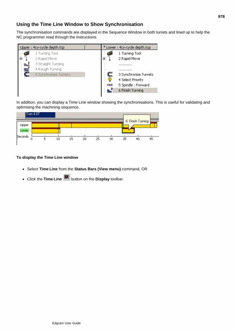
Using the Time Line Window to Show Synchronisation
The synchronisation commands are displayed in the Sequence Window in both turrets and lined up to help theNC programmer read through the instructions.
In addition, you can display a Time Line window showing the synchronisations. This is useful for validating andoptimising the machining sequence.
To display the Time Line window
Select Time Line from the Status Bars (View menu) command, OR
Click the Time Line button on the Display toolbar.
978
Edgcam User Guide
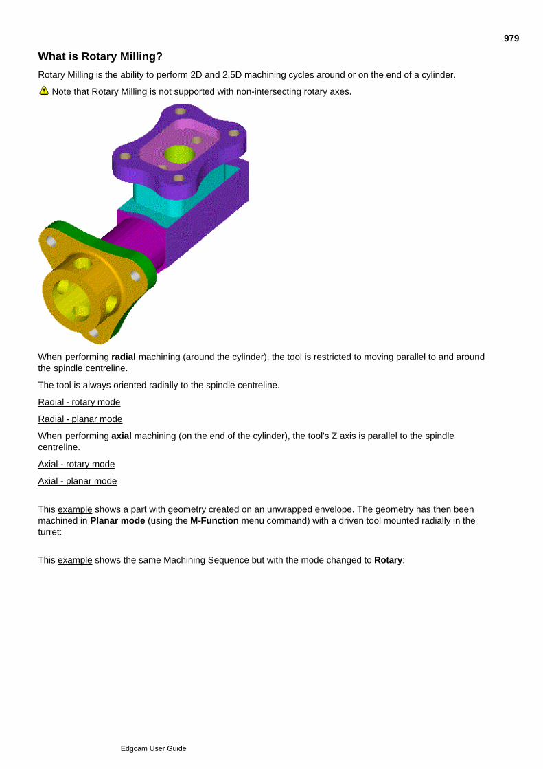
What is Rotary Milling?
Rotary Milling is the ability to perform 2D and 2.5D machining cycles around or on the end of a cylinder.
Note that Rotary Milling is not supported with non-intersecting rotary axes.
When performing radial machining (around the cylinder), the tool is restricted to moving parallel to and aroundthe spindle centreline.
The tool is always oriented radially to the spindle centreline.
Radial - rotary mode
Radial - planar mode
When performing axial machining (on the end of the cylinder), the tool's Z axis is parallel to the spindlecentreline.
Axial - rotary mode
Axial - planar mode
This example shows a part with geometry created on an unwrapped envelope. The geometry has then beenmachined in Planar mode (using the M-Function menu command) with a driven tool mounted radially in theturret:
This example shows the same Machining Sequence but with the mode changed to Rotary:
979
Edgcam User Guide

Selecting a Driven or Fixed Tool
When defining a new tool (from the Tooling menu or using the tool buttons), you need to specify the mode oftool operation.
Use the Tool Mode parameter in the toolchange command dialog to choose between:
Driven – The tool rotates (acts as a spindle) and the main spindle becomes the C axis.
Fixed – The tool is fixed and the work rotates on the main spindle. This mode is used for all standard turningoperations (and Hole cycles on the centreline of the spindle).
980
Edgcam User Guide
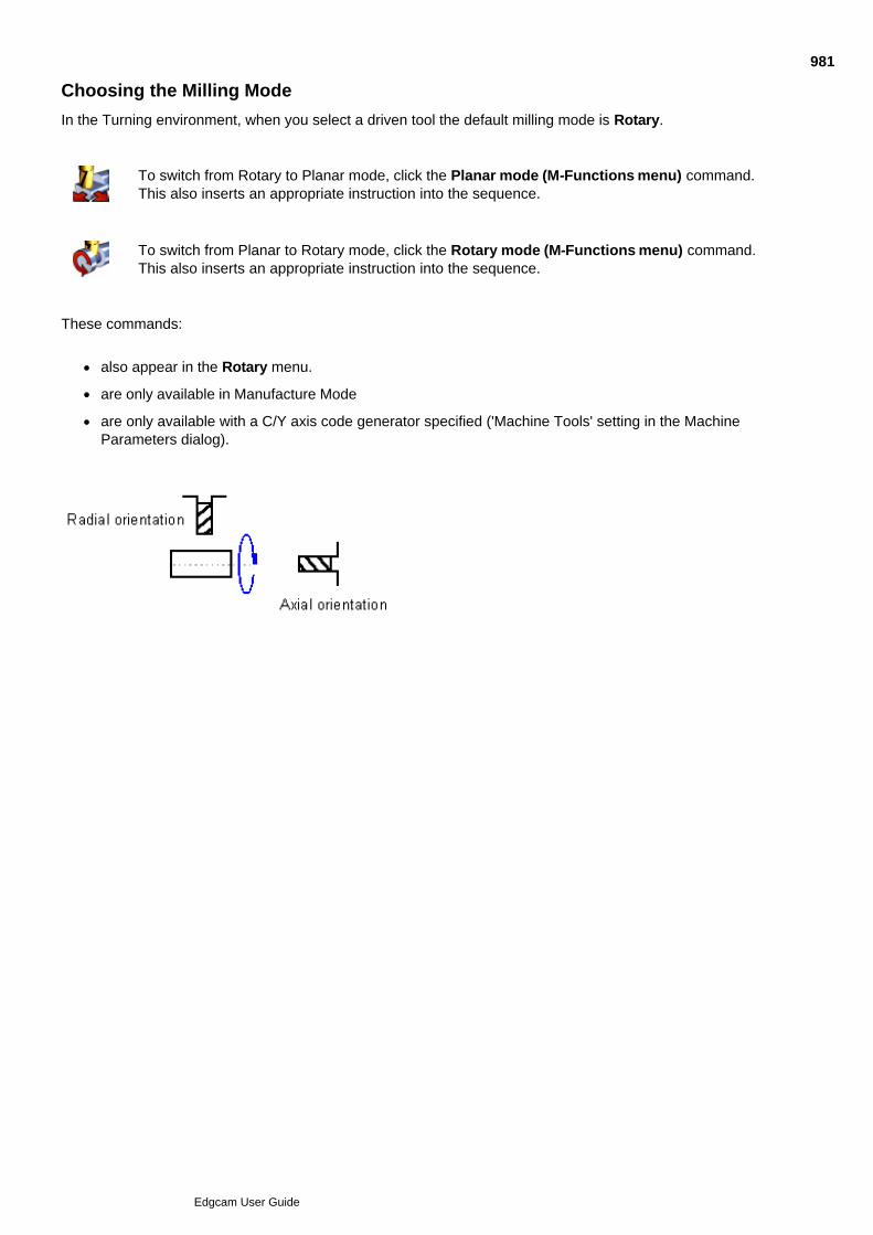
Choosing the Milling Mode
In the Turning environment, when you select a driven tool the default milling mode is Rotary.
To switch from Rotary to Planar mode, click the Planar mode (M-Functions menu) command.This also inserts an appropriate instruction into the sequence.
To switch from Planar to Rotary mode, click the Rotary mode (M-Functions menu) command.This also inserts an appropriate instruction into the sequence.
These commands:
also appear in the Rotary menu.
are only available in Manufacture Mode
are only available with a C/Y axis code generator specified ('Machine Tools' setting in the MachineParameters dialog).
981
Edgcam User Guide

Milling in Rotary Mode
Before attempting a rotary milling operation, ensure that you have selected:
a C/Y axis Code Generator Machine Tool
the Rotary mode (M-Function menu) command .
The following command is available for Rotary Milling:
Angular (Move menu)
See Also
Moving Around the Rotary Axis
Radial Milling
Axial Milling
Milling in Planar Mode (Y Axis)
Resetting the Rotary Datum
Rotating Machining Instructions
Configuring the Rotary Machining Output
Rules Used to Determine the Angular Position of the Tool
982
Edgcam User Guide

Moving Around the Rotary Axis
While milling in Rotary mode, the tool is restricted to movement along and around the rotary axis. Any linearmovement that would alter the tool's distance from the centre of rotation is wrapped to the appropriate angularposition, as shown here:
For example, on an C axis rotary machine, the tool can move along the Z axis but any Y motion is convertedinto an angular move around the C axis.
Note that you can specify an angular co-ordinate directly in the Co-ordinate Input dialog by stating the angle.You could do this, for example, by entering C90. If you had to, you could also do this by entering a distance inthe Y axis equal to one quarter of the circumference (pi times D over 4). The real use for this is when thedistance to travel was originally described as a linear distance around the cylinder.
The Angular (Move menu) command lets you specify an angular move around the spindle of the machine tool,while optionally stating a new XYZ position.
As can be seen from this diagram, the current CPL and tool remain aligned with respect to each other as thetool moves to a new angular position. The co-ordinate information is always related to the current CPL, but theAngular move is always around the spindle.
983
Edgcam User Guide
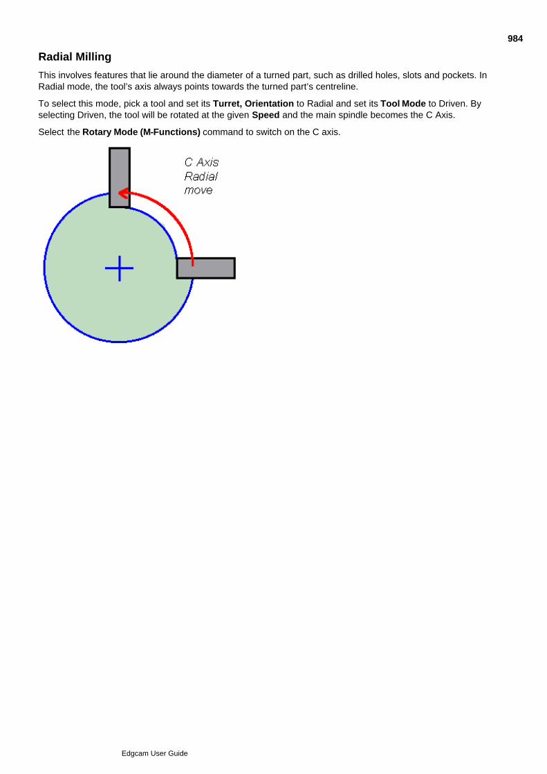
Radial Milling
This involves features that lie around the diameter of a turned part, such as drilled holes, slots and pockets. InRadial mode, the tool’s axis always points towards the turned part’s centreline.
To select this mode, pick a tool and set its Turret, Orientation to Radial and set its Tool Mode to Driven. Byselecting Driven, the tool will be rotated at the given Speed and the main spindle becomes the C Axis.
Select the Rotary Mode (M-Functions) command to switch on the C axis.
984
Edgcam User Guide
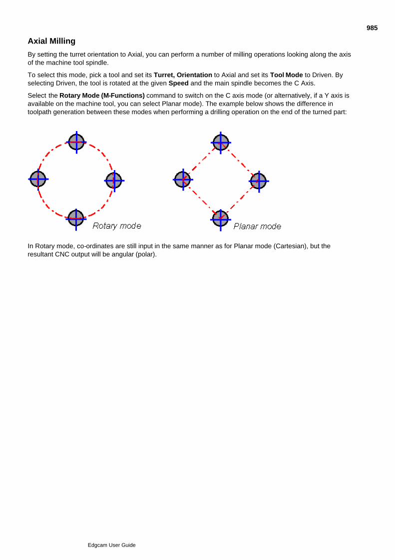
Axial Milling
By setting the turret orientation to Axial, you can perform a number of milling operations looking along the axisof the machine tool spindle.
To select this mode, pick a tool and set its Turret, Orientation to Axial and set its Tool Mode to Driven. Byselecting Driven, the tool is rotated at the given Speed and the main spindle becomes the C Axis.
Select the Rotary Mode (M-Functions) command to switch on the C axis mode (or alternatively, if a Y axis isavailable on the machine tool, you can select Planar mode). The example below shows the difference intoolpath generation between these modes when performing a drilling operation on the end of the turned part:
In Rotary mode, co-ordinates are still input in the same manner as for Planar mode (Cartesian), but theresultant CNC output will be angular (polar).
985
Edgcam User Guide
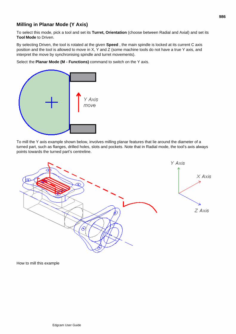
Milling in Planar Mode (Y Axis)
To select this mode, pick a tool and set its Turret, Orientation (choose between Radial and Axial) and set itsTool Mode to Driven.
By selecting Driven, the tool is rotated at the given Speed , the main spindle is locked at its current C axisposition and the tool is allowed to move in X, Y and Z (some machine tools do not have a true Y axis, andinterpret the move by synchronising spindle and turret movements).
Select the Planar Mode (M - Functions) command to switch on the Y axis.
To mill the Y axis example shown below, involves milling planar features that lie around the diameter of aturned part, such as flanges, drilled holes, slots and pockets. Note that in Radial mode, the tool’s axis alwayspoints towards the turned part’s centreline.
How to mill this example
986
Edgcam User Guide
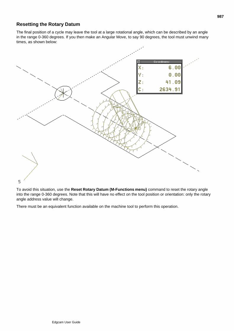
Resetting the Rotary Datum
The final position of a cycle may leave the tool at a large rotational angle, which can be described by an anglein the range 0-360 degrees. If you then make an Angular Move, to say 90 degrees, the tool must unwind manytimes, as shown below:
To avoid this situation, use the Reset Rotary Datum (M-Functions menu) command to reset the rotary angleinto the range 0-360 degrees. Note that this will have no effect on the tool position or orientation: only the rotaryangle address value will change.
There must be an equivalent function available on the machine tool to perform this operation.
987
Edgcam User Guide
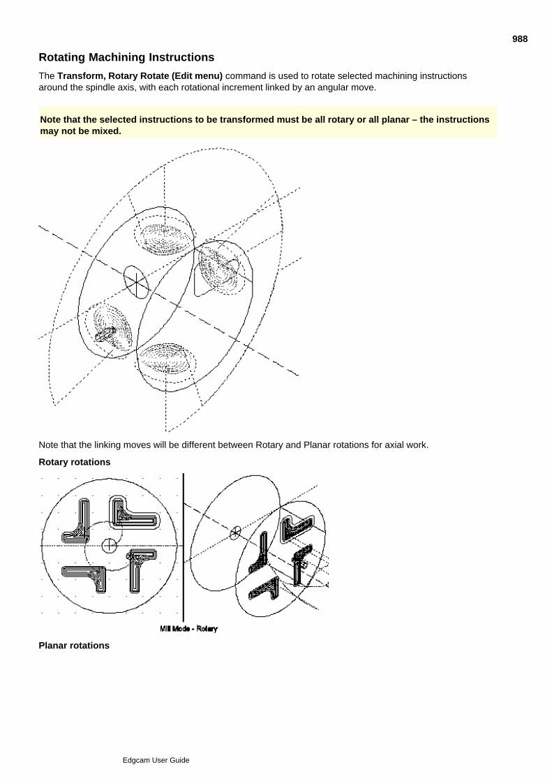
Rotating Machining Instructions
The Transform, Rotary Rotate (Edit menu) command is used to rotate selected machining instructionsaround the spindle axis, with each rotational increment linked by an angular move.
Note that the selected instructions to be transformed must be all rotary or all planar – the instructionsmay not be mixed.
Note that the linking moves will be different between Rotary and Planar rotations for axial work.
Rotary rotations
Planar rotations
988
Edgcam User Guide

989
Edgcam User Guide

Configuring the Rotary Machining Output
The Code Generator/ Wizard can be configured to output different co-ordinate information depending upon themachine tool type:
Output relative to tool depth - the standard output method. The main effect is that arcs that aremachined at a different radius will become ellipses and therefore output as a series of feed moves.
Output relative to geometry level (Wrapped radius) - for machines that can store the radiusinformation and output all toolpath data relative to that level. The main effect is that all arc information isoutput at the Wrapping radius irrespective of tool depth.
Output relative to the unwrapped (Planar) geometry - for machines with controllers that can wrapplanar toolpaths directly (all CNC information is output as if Planar mode was active).
For more information on how to select these features, see the Code Generator and Code Wizarddocumentation.
990
Edgcam User Guide

Rules Used to Determine the Angular Position of the Tool
For toolpath moves that do not have any depth parameters (Feed, Rapid etc.) the Wrap radius parameterdetermines the angular position. If you leave the Wrap Radius parameter blank, the tool position is used.
1.
For cycles that use Depth parameters (for example, Face Milling) the level determines the Wrap radius.2.
For cycles that use entities to determine the toolpath, the level of the geometry determines the WrapRadius. This ensures that the correct angular position is maintained with respect to the selectedgeometry.
3.
991
Edgcam User Guide

Angular Co-ordinate Input in Manufacture Mode
When in rotary mode, co-ordinate input can be used for entering an angular position.
For example, you can create a feed move by entering 'Y50B90' into the Co-ordinate input dialog. The tool willfeed to Y50 and rotate to B90. Note that the Wrap radius must be set correctly within the Feed dialog.
992
Edgcam User Guide

Locking the View Down the Tool Axis
The ‘Track CPL’ port is a selected user-defined port which is always orientated to view down onto the activeCPL, including Wrap CPLs.
Access to the Track CPL port is through the Track CPL parameter in the Drawing, Configure (View menu)dialog.
Select the appropriate user-defined port to become the new Track CPL port.
Select ‘None’ to de-activate the port (if it is the current Track CPL port).
Note that you must have at least one user-defined port to set a Track CPL port, since standard portscannot be re-orientated.
993
Edgcam User Guide
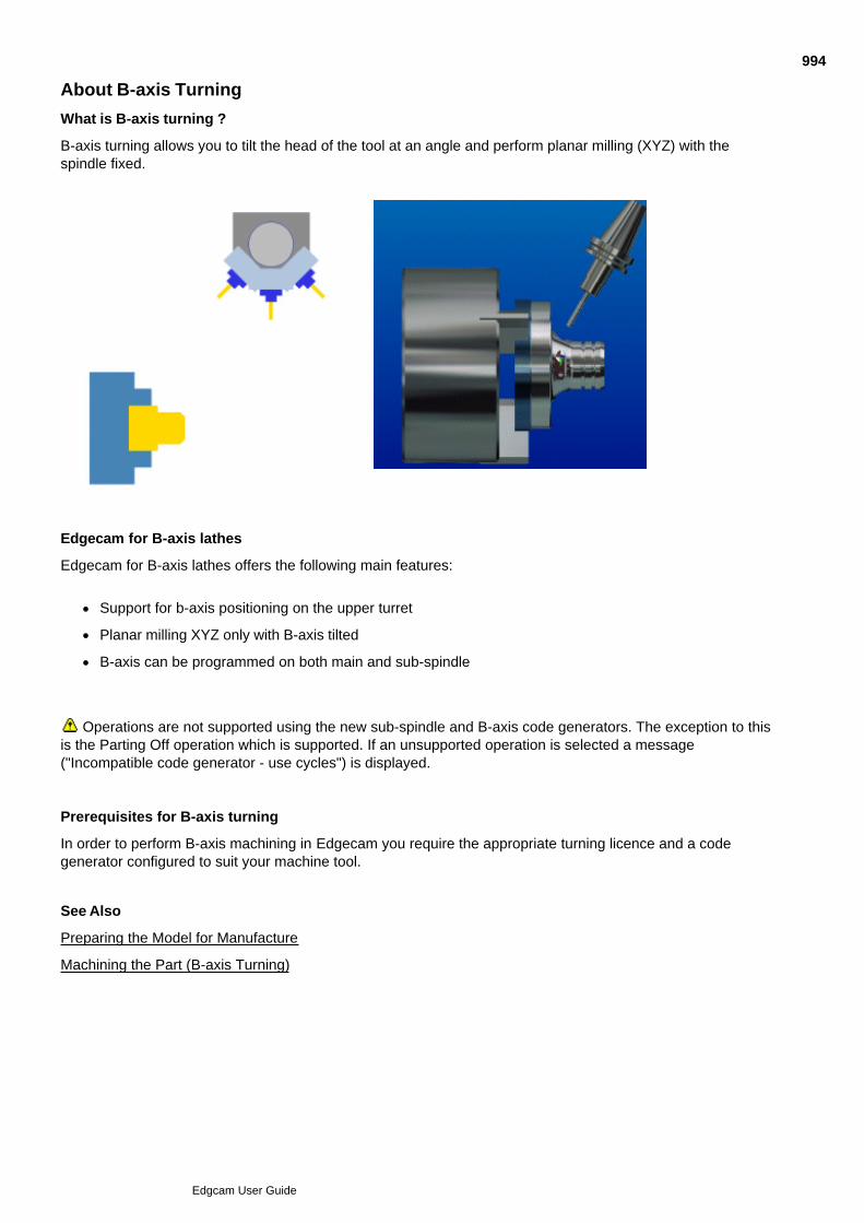
About B-axis Turning
What is B-axis turning ?
B-axis turning allows you to tilt the head of the tool at an angle and perform planar milling (XYZ) with thespindle fixed.
Edgecam for B-axis lathes
Edgecam for B-axis lathes offers the following main features:
Support for b-axis positioning on the upper turret
Planar milling XYZ only with B-axis tilted
B-axis can be programmed on both main and sub-spindle
Operations are not supported using the new sub-spindle and B-axis code generators. The exception to thisis the Parting Off operation which is supported. If an unsupported operation is selected a message("Incompatible code generator - use cycles") is displayed.
Prerequisites for B-axis turning
In order to perform B-axis machining in Edgecam you require the appropriate turning licence and a codegenerator configured to suit your machine tool.
See Also
Preparing the Model for Manufacture
Machining the Part (B-axis Turning)
994
Edgcam User Guide
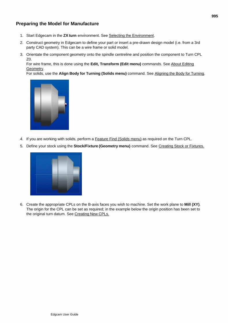
Preparing the Model for Manufacture
Start Edgecam in the ZX turn environment. See Selecting the Environment.1.
Construct geometry in Edgecam to define your part or insert a pre-drawn design model (i.e. from a 3rdparty CAD system). This can be a wire frame or solid model.
2.
Orientate the component geometry onto the spindle centreline and position the component to Turn CPLZ0. For wire frame, this is done using the Edit, Transform (Edit menu) commands. See About EditingGeometry.For solids, use the Align Body for Turning (Solids menu) command. See Aligning the Body for Turning.
3.
If you are working with solids, perform a Feature Find (Solids menu) as required on the Turn CPL.4.
Define your stock using the Stock/Fixture (Geometry menu) command. See Creating Stock or Fixtures.5.
Create the appropriate CPLs on the B-axis faces you wish to machine. Set the work plane to Mill (XY).The origin for the CPL can be set as required; in the example below the origin position has been set tothe original turn datum. See Creating New CPLs.
6.
995
Edgcam User Guide
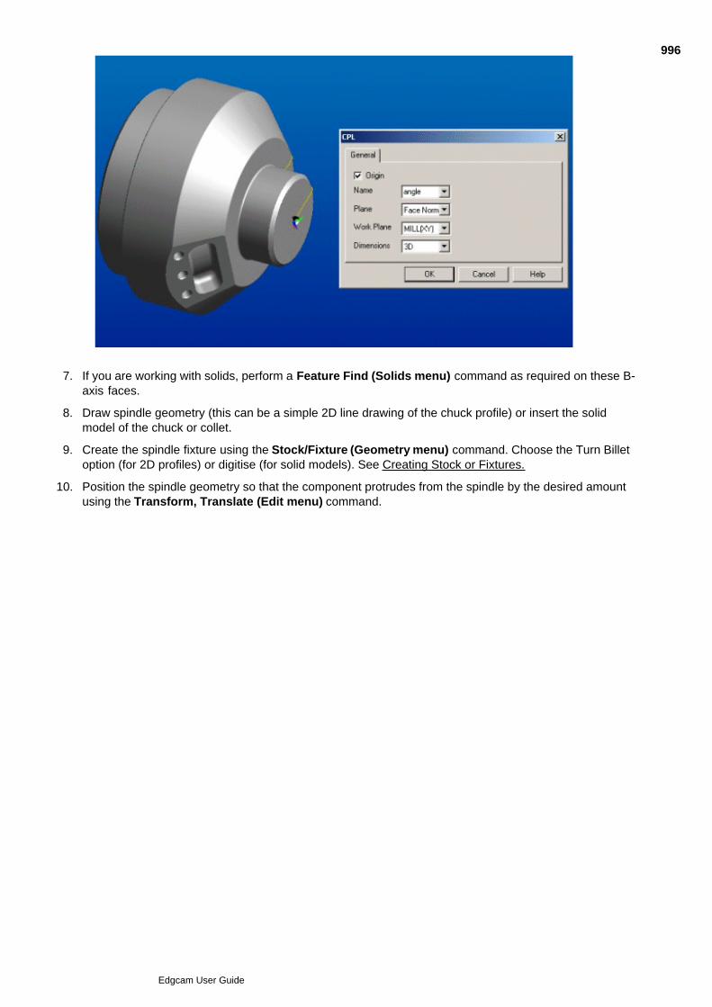
6.
If you are working with solids, perform a Feature Find (Solids menu) command as required on these B-axis faces.
7.
Draw spindle geometry (this can be a simple 2D line drawing of the chuck profile) or insert the solidmodel of the chuck or collet.
8.
Create the spindle fixture using the Stock/Fixture (Geometry menu) command. Choose the Turn Billetoption (for 2D profiles) or digitise (for solid models). See Creating Stock or Fixtures.
9.
Position the spindle geometry so that the component protrudes from the spindle by the desired amountusing the Transform, Translate (Edit menu) command.
10.
996
Edgcam User Guide
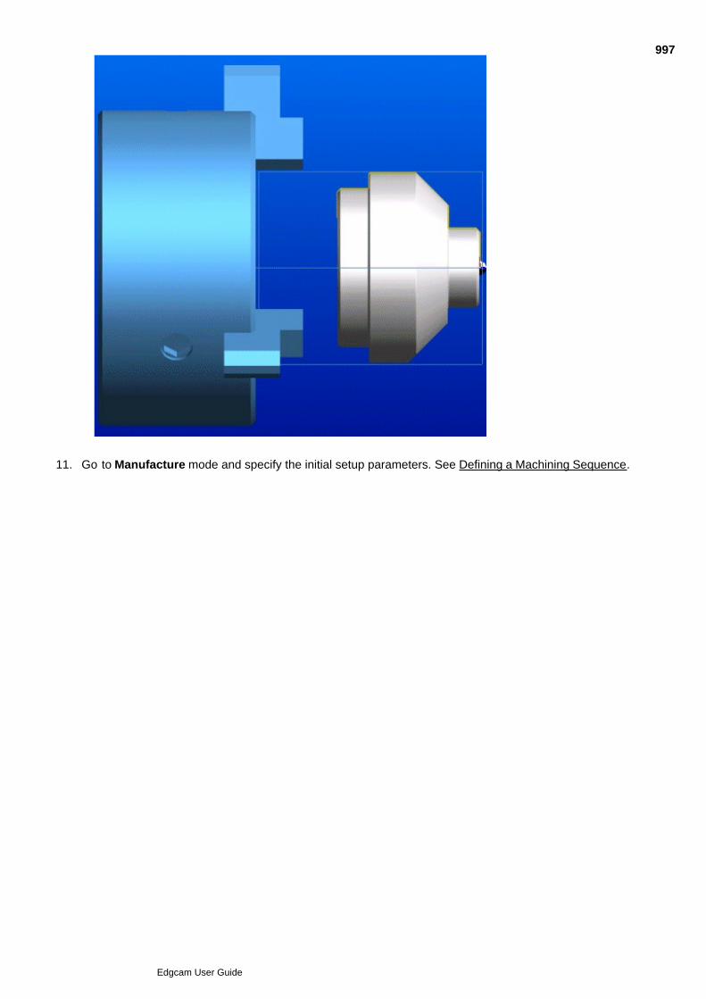
10.
Go to Manufacture mode and specify the initial setup parameters. See Defining a Machining Sequence.11.
997
Edgcam User Guide
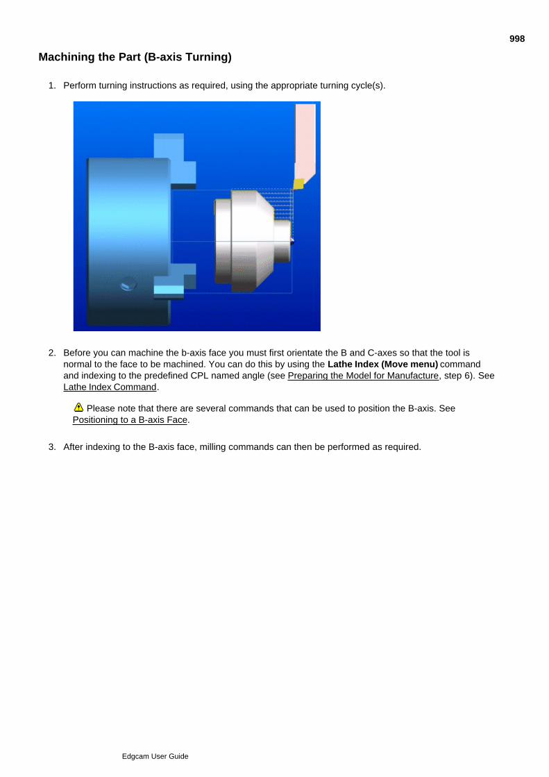
Machining the Part (B-axis Turning)
Perform turning instructions as required, using the appropriate turning cycle(s).1.
Before you can machine the b-axis face you must first orientate the B and C-axes so that the tool isnormal to the face to be machined. You can do this by using the Lathe Index (Move menu) commandand indexing to the predefined CPL named angle (see Preparing the Model for Manufacture, step 6). SeeLathe Index Command.
2.
Please note that there are several commands that can be used to position the B-axis. SeePositioning to a B-axis Face.
After indexing to the B-axis face, milling commands can then be performed as required.3.
998
Edgcam User Guide
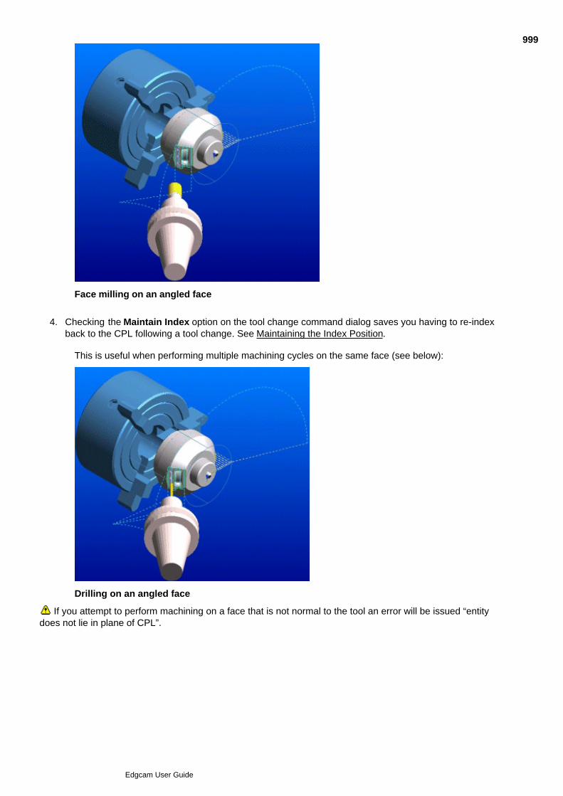
3.
Face milling on an angled face
Checking the Maintain Index option on the tool change command dialog saves you having to re-indexback to the CPL following a tool change. See Maintaining the Index Position.
4.
This is useful when performing multiple machining cycles on the same face (see below):
Drilling on an angled face
If you attempt to perform machining on a face that is not normal to the tool an error will be issued “entitydoes not lie in plane of CPL”.
999
Edgcam User Guide
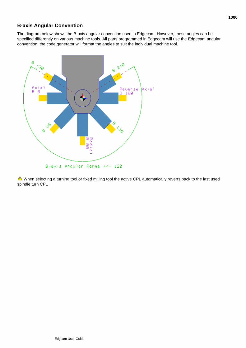
B-axis Angular Convention
The diagram below shows the B-axis angular convention used in Edgecam. However, these angles can bespecified differently on various machine tools. All parts programmed in Edgecam will use the Edgecam angularconvention; the code generator will format the angles to suit the individual machine tool.
When selecting a turning tool or fixed milling tool the active CPL automatically reverts back to the last usedspindle turn CPL
1000
Edgcam User Guide

Planar/Rotary Mode
Rotary mode is available when driven tools are positioned in the following orientations:
Axial (B0)
Reverse Axial (B180)
Radial (B90)
Note
If a CPL is selected that is offset from the centreline planar mode is forced. This means that the C-axis is fixedand you can drive only the X,Y and Z axes.
Also see
What is Rotary Milling?
1001
Edgcam User Guide
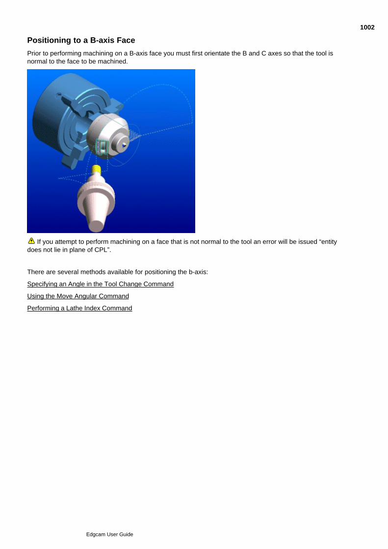
Positioning to a B-axis Face
Prior to performing machining on a B-axis face you must first orientate the B and C axes so that the tool isnormal to the face to be machined.
If you attempt to perform machining on a face that is not normal to the tool an error will be issued “entitydoes not lie in plane of CPL”.
There are several methods available for positioning the b-axis:
Specifying an Angle in the Tool Change Command
Using the Move Angular Command
Performing a Lathe Index Command
1002
Edgcam User Guide
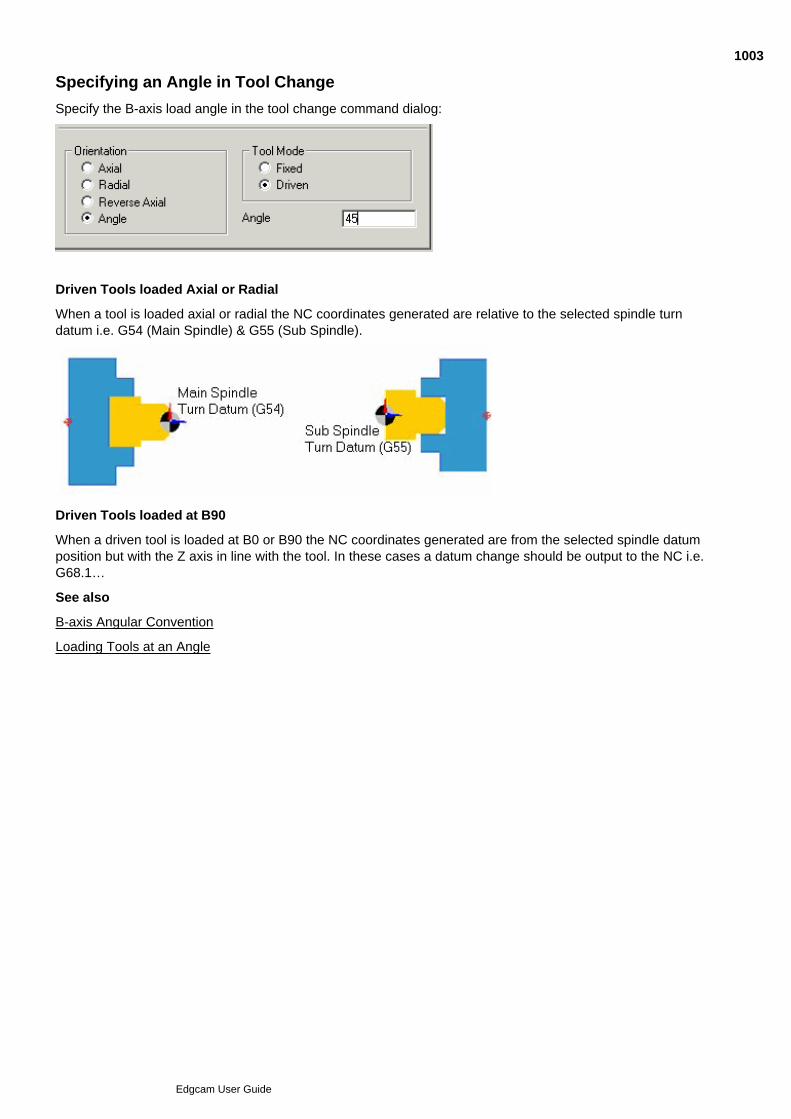
Specifying an Angle in Tool Change
Specify the B-axis load angle in the tool change command dialog:
Driven Tools loaded Axial or Radial
When a tool is loaded axial or radial the NC coordinates generated are relative to the selected spindle turndatum i.e. G54 (Main Spindle) & G55 (Sub Spindle).
Driven Tools loaded at B90
When a driven tool is loaded at B0 or B90 the NC coordinates generated are from the selected spindle datumposition but with the Z axis in line with the tool. In these cases a datum change should be output to the NC i.e.G68.1…
See also
B-axis Angular Convention
Loading Tools at an Angle
1003
Edgcam User Guide

Using Move Angular
Use Move menu Angular to open the dialog below (you can also access this help using the Help button in the dialog):
1004
Edgcam User Guide

Lathe Index Command
Use Move menu Lathe Index to open the dialog below.
(You can also access this help using the cycle dialog's Help button.)
1005
Edgcam User Guide
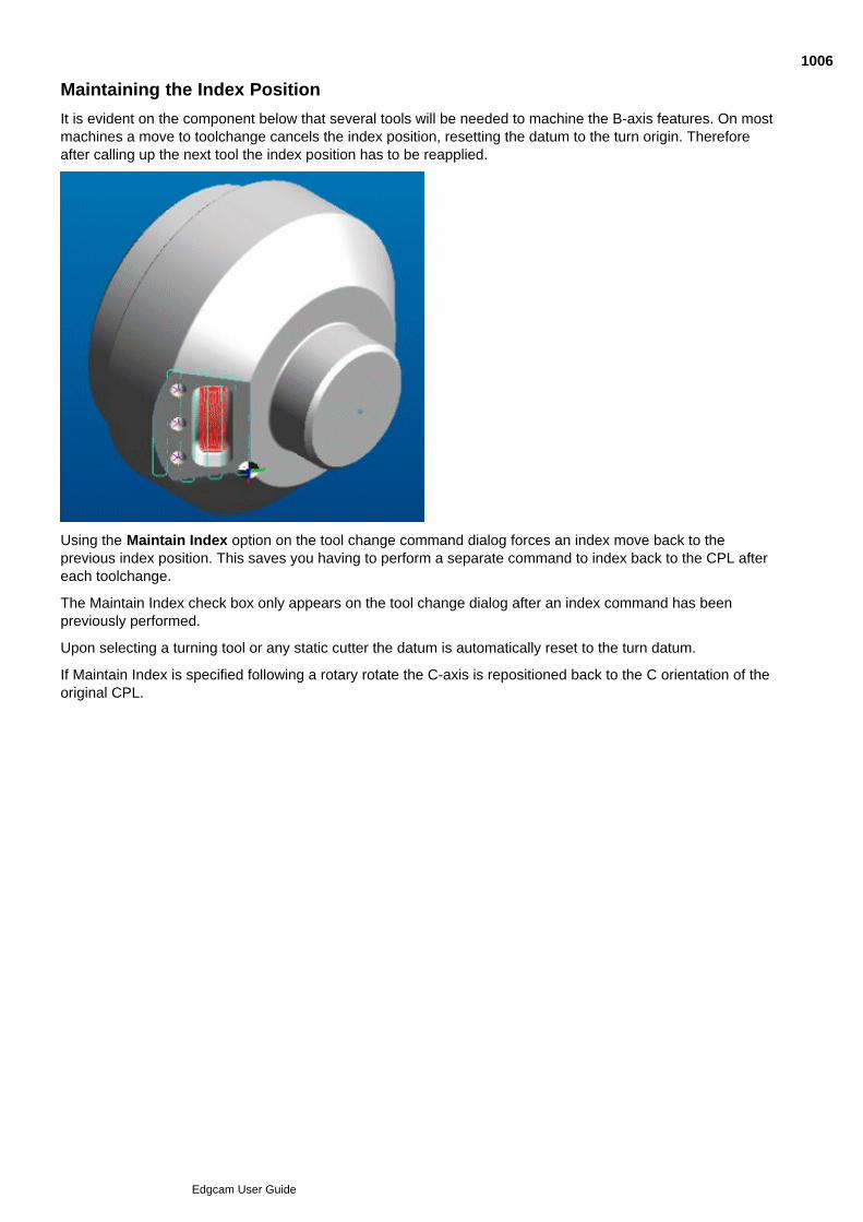
Maintaining the Index Position
It is evident on the component below that several tools will be needed to machine the B-axis features. On mostmachines a move to toolchange cancels the index position, resetting the datum to the turn origin. Thereforeafter calling up the next tool the index position has to be reapplied.
Using the Maintain Index option on the tool change command dialog forces an index move back to theprevious index position. This saves you having to perform a separate command to index back to the CPL aftereach toolchange.
The Maintain Index check box only appears on the tool change dialog after an index command has beenpreviously performed.
Upon selecting a turning tool or any static cutter the datum is automatically reset to the turn datum.
If Maintain Index is specified following a rotary rotate the C-axis is repositioned back to the C orientation of theoriginal CPL.
1006
Edgcam User Guide

Using Rotary Rotate
Use Edit menu Transform Rotary Rotate to open the dialog below.
(you can also access this help by clicking the Help button in the dialog):
1007
Edgcam User Guide
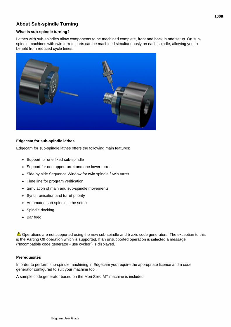
About Sub-spindle Turning
What is sub-spindle turning?
Lathes with sub-spindles allow components to be machined complete, front and back in one setup. On sub-spindle machines with twin turrets parts can be machined simultaneously on each spindle, allowing you tobenefit from reduced cycle times.
Edgecam for sub-spindle lathes
Edgecam for sub-spindle lathes offers the following main features:
Support for one fixed sub-spindle
Support for one upper turret and one lower turret
Side by side Sequence Window for twin spindle / twin turret
Time line for program verification
Simulation of main and sub-spindle movements
Synchronisation and turret priority
Automated sub-spindle lathe setup
Spindle docking
Bar feed
Operations are not supported using the new sub-spindle and b-axis code generators. The exception to thisis the Parting Off operation which is supported. If an unsupported operation is selected a message("Incompatible code generator - use cycles") is displayed.
Prerequisites
In order to perform sub-spindle machining in Edgecam you require the appropriate licence and a codegenerator configured to suit your machine tool.
A sample code generator based on the Mori Seiki MT machine is included.
1008
Edgcam User Guide

See also
Preparing the Model for Manufacture
Machining the Part in Sub-spindle Turning
1009
Edgcam User Guide

Setting up Sub-Spindle Turning
You create a sub-spindle machining setup when you create the machining sequence, using the Lathe Setuptab, as explained below. (Note that if necessary you can change the your setup.)
(You can also access this help using the dialog's Help button.)
1010
Edgcam User Guide

Editing the Sub-Spindle Setup
Once you have created a sub-spindle setup, you might find you need to adjust this.
Click the M-Functions menu Lathe Setup. to open the dialog below (you can alsoaccess this help using the Help button in the dialog).
1011
Edgcam User Guide
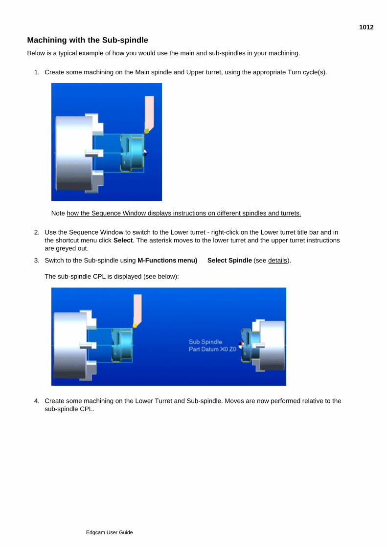
Machining with the Sub-spindle
Below is a typical example of how you would use the main and sub-spindles in your machining.
Create some machining on the Main spindle and Upper turret, using the appropriate Turn cycle(s).1.
Note how the Sequence Window displays instructions on different spindles and turrets.
Use the Sequence Window to switch to the Lower turret - right-click on the Lower turret title bar and inthe shortcut menu click Select. The asterisk moves to the lower turret and the upper turret instructionsare greyed out.
2.
Switch to the Sub-spindle using M-Functions menu) Select Spindle (see details).
The sub-spindle CPL is displayed (see below):
3.
Create some machining on the Lower Turret and Sub-spindle. Moves are now performed relative to thesub-spindle CPL.
4.
1012
Edgcam User Guide
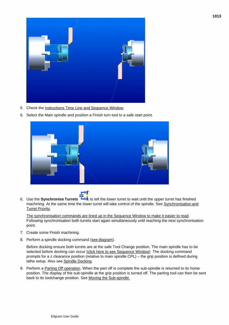
4.
Check the instructions Time Line and Sequence Window.5.
Select the Main spindle and position a Finish turn tool to a safe start point.6.
Use the Synchronise Turrets to tell the lower turret to wait until the upper turret has finishedmachining. At the same time the lower turret will take control of the spindle. See Synchronisation andTurret Priority.
The synchronisation commands are lined up in the Sequence Window to make it easier to read.Following synchronisation both turrets start again simultaneously until reaching the next synchronisationpoint.
6.
Create some Finish machining.7.
Perform a spindle docking command (see diagram).
Before docking ensure both turrets are at the safe Tool Change position. The main spindle has to beselected before docking can occur (click here to see Sequence Window) The docking commandprompts for a z clearance position (relative to main spindle CPL) – the grip position is defined duringlathe setup. Also see Spindle Docking.
8.
Perform a Parting Off operation. When the part off is complete the sub-spindle is returned to its homeposition. The display of the sub-spindle at the grip position is turned off. The parting tool can then be sentback to its toolchange position. See Moving the Sub-spindle.
9.
10.
1013
Edgcam User Guide

9.
A bar feed can be performed to set up the main spindle stock for the next program run through. To dothis, load a bar stop tool and select the Bar Feed (Move menu) cycle. See Bar Feed Cycle.
10.
The instruction list shows a complete sub-spindle machining sequence.
The time line can be used as a validation tool to ensure synchronisation positions are correctly placed.Edgecam simulation with the Constant option unchecked also gives a good indication that the synchronisationpositions are correctly placed.
Click View menu Simulate Batch. Bar feed is programmed typically at the beginning or end of themachining sequence. To simulate bar feed you need to run the simulation in batch mode. If bar feed is at theend of the sequence check Initial Stock , this means the main spindle stock defined in Edgecam will bedisplayed as soon as you start Simulator. Specify the number of times you want the simulation to run byspecifying the Batch Size. See Sub-Spindle Simulation.
Please note that in sub-spindle turning, two instances of stock can be machined independently. The FeaturesWindow is used to assign the stock to the main spindle or the sub-spindle respectively. See Assigning Stockand Fixtures for Sub-Spindle Simulation.
1014
Edgcam User Guide
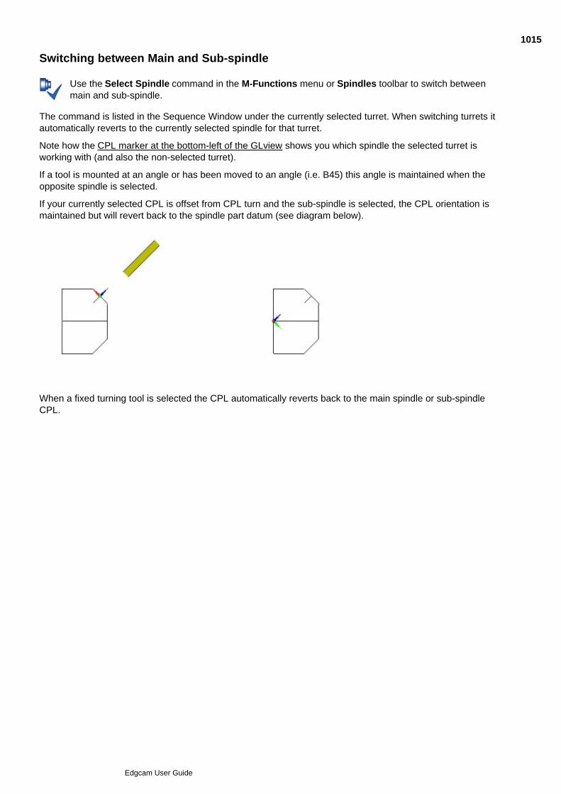
Switching between Main and Sub-spindle
Use the Select Spindle command in the M-Functions menu or Spindles toolbar to switch betweenmain and sub-spindle.
The command is listed in the Sequence Window under the currently selected turret. When switching turrets itautomatically reverts to the currently selected spindle for that turret.
Note how the CPL marker at the bottom-left of the GLview shows you which spindle the selected turret isworking with (and also the non-selected turret).
If a tool is mounted at an angle or has been moved to an angle (i.e. B45) this angle is maintained when theopposite spindle is selected.
If your currently selected CPL is offset from CPL turn and the sub-spindle is selected, the CPL orientation ismaintained but will revert back to the spindle part datum (see diagram below).
When a fixed turning tool is selected the CPL automatically reverts back to the main spindle or sub-spindleCPL.
1015
Edgcam User Guide

Bar Pulling
Use Move menu Move Bar Pull to open the dialog below.
(You can also access this help using the cycle dialog's Help button.)
1016
Edgcam User Guide
Sub-Spindle Docking
Use Move menu Spindle Docking to open the dialog below.
(You can also access this help using the cycle dialog's Help button.)
1017
Edgcam User Guide

Moving the Sub-spindle
Use Move menu Move Sub Spindle to open the dialog below.
(You can also access this help using the cycle dialog's Help button.)
1018
Edgcam User Guide
Using the Bar Feed Cycle
Use Bar Feed (Move menu) to set up the main spindle stock for the next program run through.
Prior to selecting the command perform a tool change to select a bar stop device; this must be a fixed tool. Themain spindle needs be selected as the coordinates for the cycle are relative to the main spindle part datum.
Choose one of three different strategies to control the bar stop movements, depending on the type ofbar stop device being used.
1.
Z First – Move the z-axis first
X First – Move the x-axis first
Direct – Move z and x-axis together
Specify the Feedrate at which bar stop is traversed in units per minute or units per revolution.2.
Specify the Speed at which the spindle rotates in revolutions per minute.3.
Specify a Dwell Time in seconds. This will be applied to each dwell point in the process.4.
After specifying the dialog parameters you are prompted for an approach, start and end position. These can bedigitised or specified using coordinate input. The bar feed cycle generates standard tool movements inEdgecam but makes no attempt to control the display of the stock feeding out.
The bar feed is typically performed at the start or end of the machining sequence (see below for an example ofa typical bar feed process).
Advance the bar stop device to X and Z approach position at rapid rate.1.
Advance the bar stop device to X and Z start position at feed rate.2.
Open main spindle C. The bar will now be applying pressure against the bar stop.3.
Dwell (time it takes for the chuck to open).4.
Feed out to Z end.5.
Close chuck.6.
Dwell (time it takes for chuck to close). You must ensure that chuck is closed before moving off.7.
1019
Edgcam User Guide

Synchronising Turrets
To synchronise turrets follow the procedure in Synchronising Turrets.
Where the procedure contains information specific to a code generator type (adaptive or non-adaptive), it is theadaptive information which is applicable (sub-spindle code generators are based on adaptive templates).
1020
Edgcam User Guide
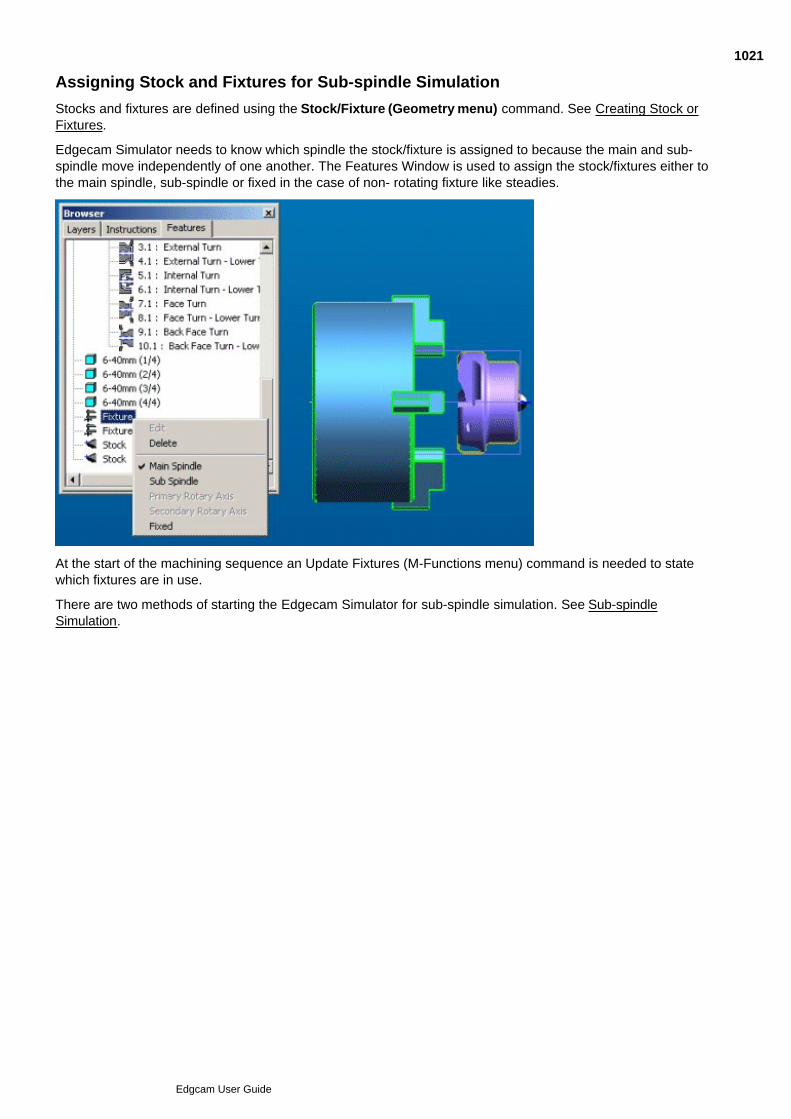
Assigning Stock and Fixtures for Sub-spindle Simulation
Stocks and fixtures are defined using the Stock/Fixture (Geometry menu) command. See Creating Stock orFixtures.
Edgecam Simulator needs to know which spindle the stock/fixture is assigned to because the main and sub-spindle move independently of one another. The Features Window is used to assign the stock/fixtures either tothe main spindle, sub-spindle or fixed in the case of non- rotating fixture like steadies.
At the start of the machining sequence an Update Fixtures (M-Functions menu) command is needed to statewhich fixtures are in use.
There are two methods of starting the Edgecam Simulator for sub-spindle simulation. See Sub-spindleSimulation.
1021
Edgcam User Guide
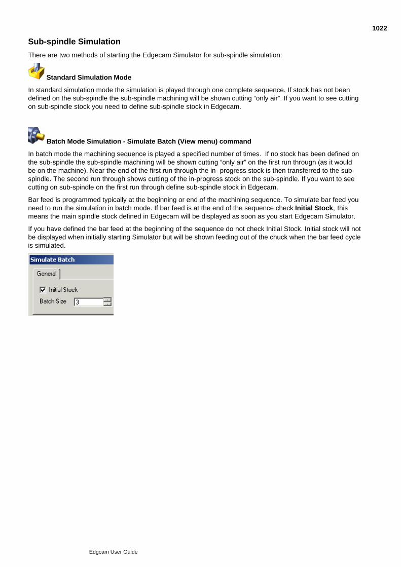
Sub-spindle Simulation
There are two methods of starting the Edgecam Simulator for sub-spindle simulation:
Standard Simulation Mode
In standard simulation mode the simulation is played through one complete sequence. If stock has not beendefined on the sub-spindle the sub-spindle machining will be shown cutting “only air”. If you want to see cuttingon sub-spindle stock you need to define sub-spindle stock in Edgecam.
Batch Mode Simulation - Simulate Batch (View menu) command
In batch mode the machining sequence is played a specified number of times. If no stock has been defined onthe sub-spindle the sub-spindle machining will be shown cutting “only air” on the first run through (as it wouldbe on the machine). Near the end of the first run through the in- progress stock is then transferred to the sub-spindle. The second run through shows cutting of the in-progress stock on the sub-spindle. If you want to seecutting on sub-spindle on the first run through define sub-spindle stock in Edgecam.
Bar feed is programmed typically at the beginning or end of the machining sequence. To simulate bar feed youneed to run the simulation in batch mode. If bar feed is at the end of the sequence check Initial Stock, thismeans the main spindle stock defined in Edgecam will be displayed as soon as you start Edgecam Simulator.
If you have defined the bar feed at the beginning of the sequence do not check Initial Stock. Initial stock will notbe displayed when initially starting Simulator but will be shown feeding out of the chuck when the bar feed cycleis simulated.
1022
Edgcam User Guide

What is Edgecam Wire Erosion?
Edgecam Wire Erosion lets you define the profiles and information for the part (“Design Intent”) and also togenerate the toolpath information. This data can then be processed into CNC code for an appropriate Two orFour Axis wire erosion machine.
A 3D model can be generated from 2D profiles using any of the following Design Intent strategies:
Transformed Profile (Geometry menu) – Uses a 2D profile that has had any of the following transformationscombinations applied:
Scaling
Movement in the co-ordinate plane
Rotation about a point
This example shows a polygonal profile containing all these transformations.
Tapered Profile (Geometry menu) – Applies a start and end taper to a 2D profile consisting of lines and arcs.You nominate matching conditions for upper and lower profiles and blending conditions with adjacent entities(see example).
Linked Profile (Geometry menu) – Used to link (manually or automatically) two separate 2D profiles ofdifferent heights, using closest node, closest position, proportional, or node-to-node strategies (see example).
Any Design Intent element is easily modified using the Entity Data (Edit menu) commands. Note that to edit alink on a Linked Profile, you must use the Entity Data, Link Profile (Edit menu) command.
The Wire Section (Geometry menu) command lets you add section lines to help visualise the Design Intent.
Manufacturing the part is simple; because most of the information is already contained in the Design Intent,only a few main commands are required:
Select Wire (Wire Cycles menu) – Specifies the wire diameter and upper & lower guide levels.
Machine Design (Wire Cycles menu) – Machines the selected Design Intent, allowing you to nominate thesupport tag size, cutting strategy and lead parameters.
2D Destruct (Wire Cycles menu) - Erodes all material inside an area defined by closed 2D geometry, whileensuring that no solid piece is freed to drop from the component.
2D Profile (Mill Cycles menu) – Profiles around selected 2D geometry.
Cut Support Tag (Wire Cycles menu) – Machines any support tags remaining from a previous wire machiningcycle.
CNC code is produced by Code Generator files with the extension *.WCP. The Code Generator files alsoprovide access to a variety of system variables and commands.
1023
Edgcam User Guide

Wire Erosion Basics
When machining a part in Edgecam Wire, you would typically go through these stages:
Creating the Design Intent
Editing the Design Intent
Entering Manufacture Mode and selecting the Code Generator
Cutting the Part
Viewing and checking the Part
Editing the Instruction List (if necessary)
Generating CNC Code
In Edgecam Wire Erosion, you apply manufacturing information to a part in Design mode before enteringManufacture mode. This lets you see the manufacturing data on-screen, so that you can easily modify theprofile elements to produce the form you want.
1024
Edgcam User Guide
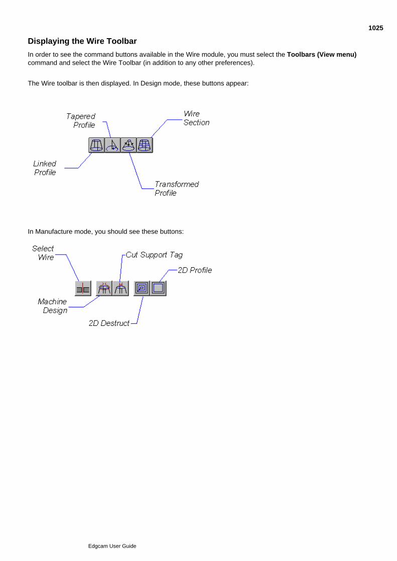
Displaying the Wire Toolbar
In order to see the command buttons available in the Wire module, you must select the Toolbars (View menu)command and select the Wire Toolbar (in addition to any other preferences).
The Wire toolbar is then displayed. In Design mode, these buttons appear:
In Manufacture mode, you should see these buttons:
1025
Edgcam User Guide

Creating the Design Intent
You will be creating the profile as 2D geometry, so you must start in Design mode in the XY environment.
Once you have defined the initial profile geometry, you must decide on how you want to cut the profile.Edgecam provides three main cutting strategies to generate Wire profiles:
Linked Profile (Geometry menu)
Tapered Profile (Geometry menu)
Transformed Profile (Geometry menu)
Wire Section (Geometry menu)
You select one of these commands to generate the manufacturing information (“Design Intent”) within Designmode. Wire Erosion is the only manufacturing discipline in Edgecam that works in this way - all other modulescreate all manufacturing information and toolpaths in Manufacture mode.
1026
Edgcam User Guide

Tapered Profiles
The simplest method of Wire Erosion is to drive the wire around a single profile. The wire can be held verticallyor at a specified angle.
You can do this using the Tapered Profile (Geometry menu) command.
You might use a Tapered Profile where a circular profile is tapered down to a smaller profile to form a plugshape.
The Tapered Profile command generates Design Intent data from a selected profile. Taper parametersdetermine the wire orientation. Lines and arcs attached to the profile element display the effect of thecommand’s parameters.
For code generation purposes, Edgecam defines the selected profile in XY co-ordinates and the generatedprofile in UV co-ordinates.
Once you are happy with the Design Intent, you may create the toolpath by using the Manufacture modecommand Machine Design (Wire Cycles menu).
See Also
Creating 2D Profiles
Creating Tapered Profiles
Using Parameters for Tapered Profile
Using Arc Parameters for Tapered Profile
1027
Edgcam User Guide
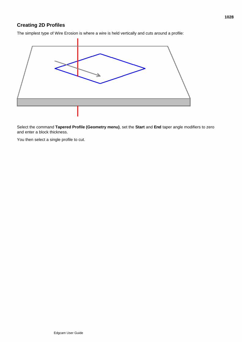
Creating 2D Profiles
The simplest type of Wire Erosion is where a wire is held vertically and cuts around a profile:
Select the command Tapered Profile (Geometry menu), set the Start and End taper angle modifiers to zeroand enter a block thickness.
You then select a single profile to cut.
1028
Edgcam User Guide
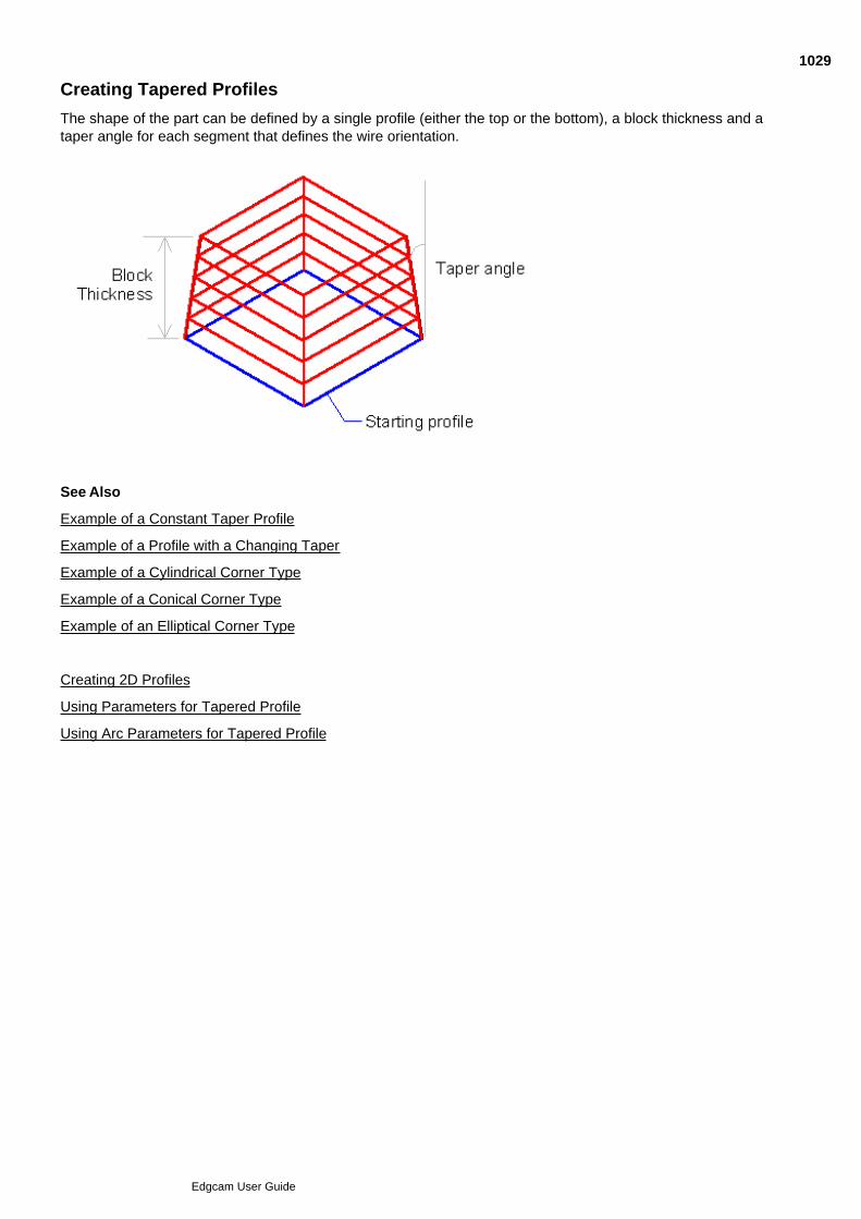
Creating Tapered Profiles
The shape of the part can be defined by a single profile (either the top or the bottom), a block thickness and ataper angle for each segment that defines the wire orientation.
See Also
Example of a Constant Taper Profile
Example of a Profile with a Changing Taper
Example of a Cylindrical Corner Type
Example of a Conical Corner Type
Example of an Elliptical Corner Type
Creating 2D Profiles
Using Parameters for Tapered Profile
Using Arc Parameters for Tapered Profile
1029
Edgcam User Guide
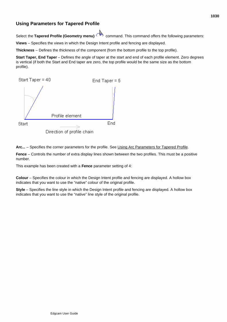
Using Parameters for Tapered Profile
Select the Tapered Profile (Geometry menu) command. This command offers the following parameters:
Views – Specifies the views in which the Design Intent profile and fencing are displayed.
Thickness – Defines the thickness of the component (from the bottom profile to the top profile).
Start Taper, End Taper – Defines the angle of taper at the start and end of each profile element. Zero degreesis vertical (if both the Start and End taper are zero, the top profile would be the same size as the bottomprofile).
Arc... – Specifies the corner parameters for the profile. See Using Arc Parameters for Tapered Profile.
Fence – Controls the number of extra display lines shown between the two profiles. This must be a positivenumber.
This example has been created with a Fence parameter setting of 4:
Colour – Specifies the colour in which the Design Intent profile and fencing are displayed. A hollow boxindicates that you want to use the “native” colour of the original profile.
Style – Specifies the line style in which the Design Intent profile and fencing are displayed. A hollow boxindicates that you want to use the “native” line style of the original profile.
1030
Edgcam User Guide

Using Arc Parameters for Tapered Profile
From the Tapered Profile parameter window, go to the Arc tab. This tab offers the following parameters:
Ellipse – Check this box for a 90° corner to be treated as an ellipse (the Corner Type modifier must also be setto Elliptical). This is the default condition. If the box is empty, such a corner is treated as a spiral.
Radius – Forces the opposing arc to have this specified radius.
Start/End Condition – Defines the blending condition with the previous (Start) or next (End) segment. Choosebetween the Step and Intersect conditions:
Step – Use this condition to change the taper abruptly from one segment to another, with a “step”.
Intersect – Use this condition to blend the taper from one segment to another.
Corner Type – Controls the taper condition around the arc. You can select from Cylindrical, Elliptical orConical.
Click here to view the various corner types under constant and changing taper conditions.
1031
Edgcam User Guide
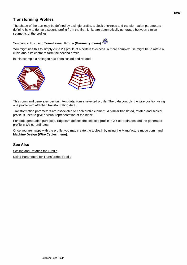
Transforming Profiles
The shape of the part may be defined by a single profile, a block thickness and transformation parametersdefining how to derive a second profile from the first. Links are automatically generated between similarsegments of the profiles.
You can do this using Transformed Profile (Geometry menu) .
You might use this to simply cut a 2D profile of a certain thickness. A more complex use might be to rotate acircle about its centre to form the second profile.
In this example a hexagon has been scaled and rotated:
This command generates design intent data from a selected profile. The data controls the wire position usingone profile with attached transformation data.
Transformation parameters are associated to each profile element. A similar translated, rotated and scaledprofile is used to give a visual representation of the block.
For code generation purposes, Edgecam defines the selected profile in XY co-ordinates and the generatedprofile in UV co-ordinates.
Once you are happy with the profile, you may create the toolpath by using the Manufacture mode commandMachine Design (Wire Cycles menu).
See Also
Scaling and Rotating the Profile
Using Parameters for Transformed Profile
1032
Edgcam User Guide
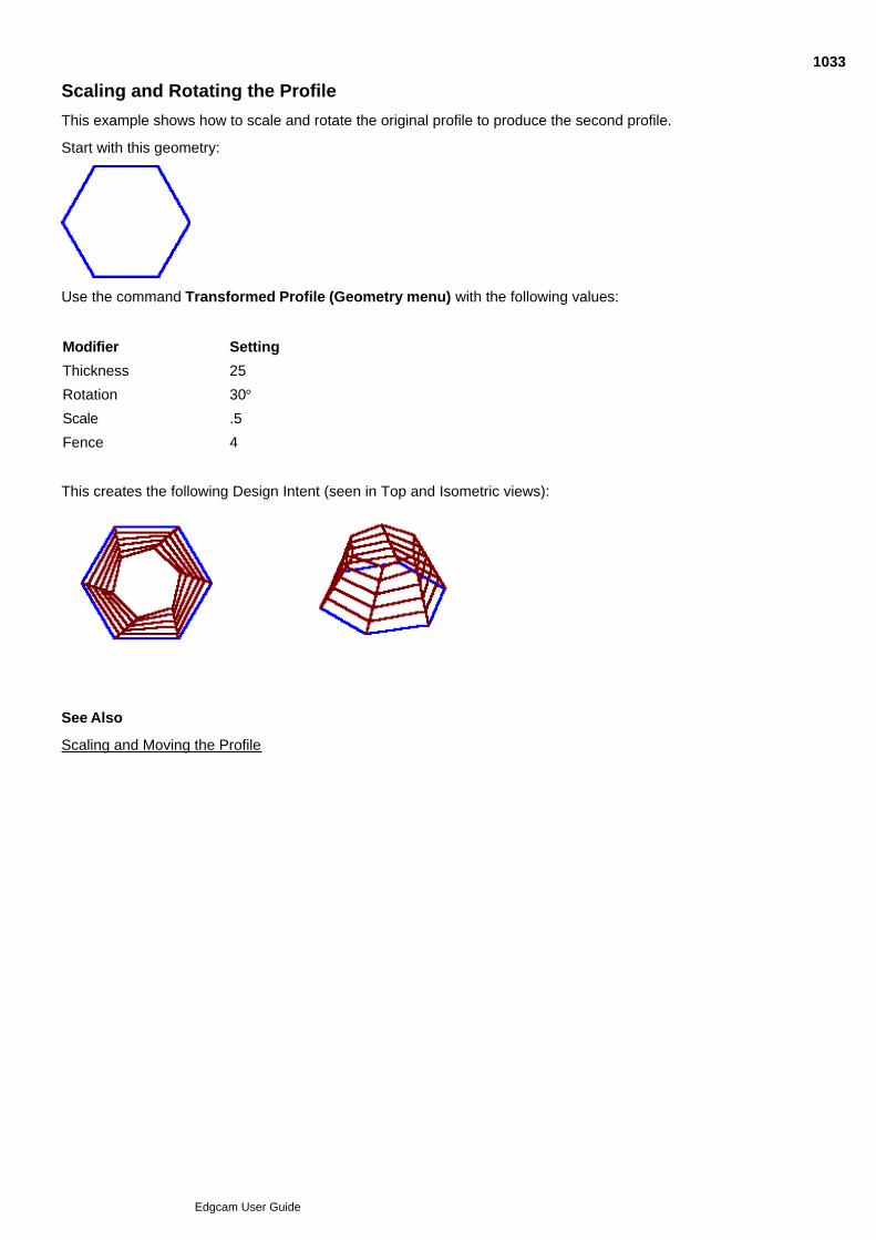
Scaling and Rotating the Profile
This example shows how to scale and rotate the original profile to produce the second profile.
Start with this geometry:
Use the command Transformed Profile (Geometry menu) with the following values:
Modifier Setting
Thickness 25
Rotation 30°
Scale .5
Fence 4
This creates the following Design Intent (seen in Top and Isometric views):
See Also
Scaling and Moving the Profile
1033
Edgcam User Guide
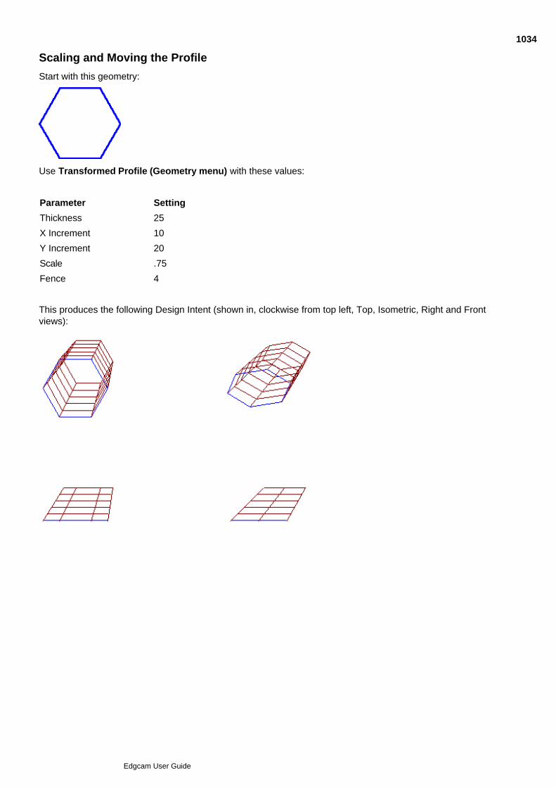
Scaling and Moving the Profile
Start with this geometry:
Use Transformed Profile (Geometry menu) with these values:
Parameter Setting
Thickness 25
X Increment 10
Y Increment 20
Scale .75
Fence 4
This produces the following Design Intent (shown in, clockwise from top left, Top, Isometric, Right and Frontviews):
1034
Edgcam User Guide

Using Parameters for Transformed Profile
The Transformed Profile (Geometry menu) parameters are:
Views – Specifies the views in which the Design Intent profile and fencing are displayed.
Thickness – Defines the plate thickness of the material.
X Increment – Specify the displacement in X from the original profile.
Y Increment – Specify the displacement in Y from the original profile
Rotation – Specify the rotation in degrees from the original profile.
Scale – Specify the enlargement factor for the second profile.
Fence – Controls the number of extra display lines shown between the two profiles. This must be a positivenumber.
This example has been created with a Fence parameter setting of 4.
Colour – Specifies the colour in which the Design Intent profile and fencing are displayed. A hollow boxindicates that you want to use the “native” colour of the original profile.
Style – Specifies the line style in which the Design Intent profile and fencing are displayed. A hollow boxindicates that you want to use the “native” line style of the original profile.
1035
Edgcam User Guide

Linking Two Profiles
A wire profile can be defined by a profile at the top and bottom of the block. The wire is oriented by linkingpositions on the upper profile to positions on the lower profile. You can do this in Edgecam using the Linked
Profile (Geometry menu) command.
You might want to use a Linked Profile on a part with different upper and lower profiles, for example a lowerrectangular profile and an upper circular profile.
The command generates design intent data for two selected profiles. This data controls the wire position andorientation using these profiles.
Note that you may not use a window to select the profiles.
Links define locations where the wire passes through both profiles: you digitise a node on the first profile andthen link it to a node on the second profile. You can create these links either automatically or manually.
The link is represented by a line from the first to the second location. The line is attached to both the first andthe second profile element.
For code generation purposes, Edgecam defines the first selected profile in XY co-ordinates and the lastselected profile in UV co-ordinates.
Once you are satisfied with the profile, you may create the toolpath by using the Manufacture mode commandMachine Design (Wire Cycles menu).
See Also
Using Parameters for Linked Profile
Using Automatic Links
Linking Profiles Manually
1036
Edgcam User Guide
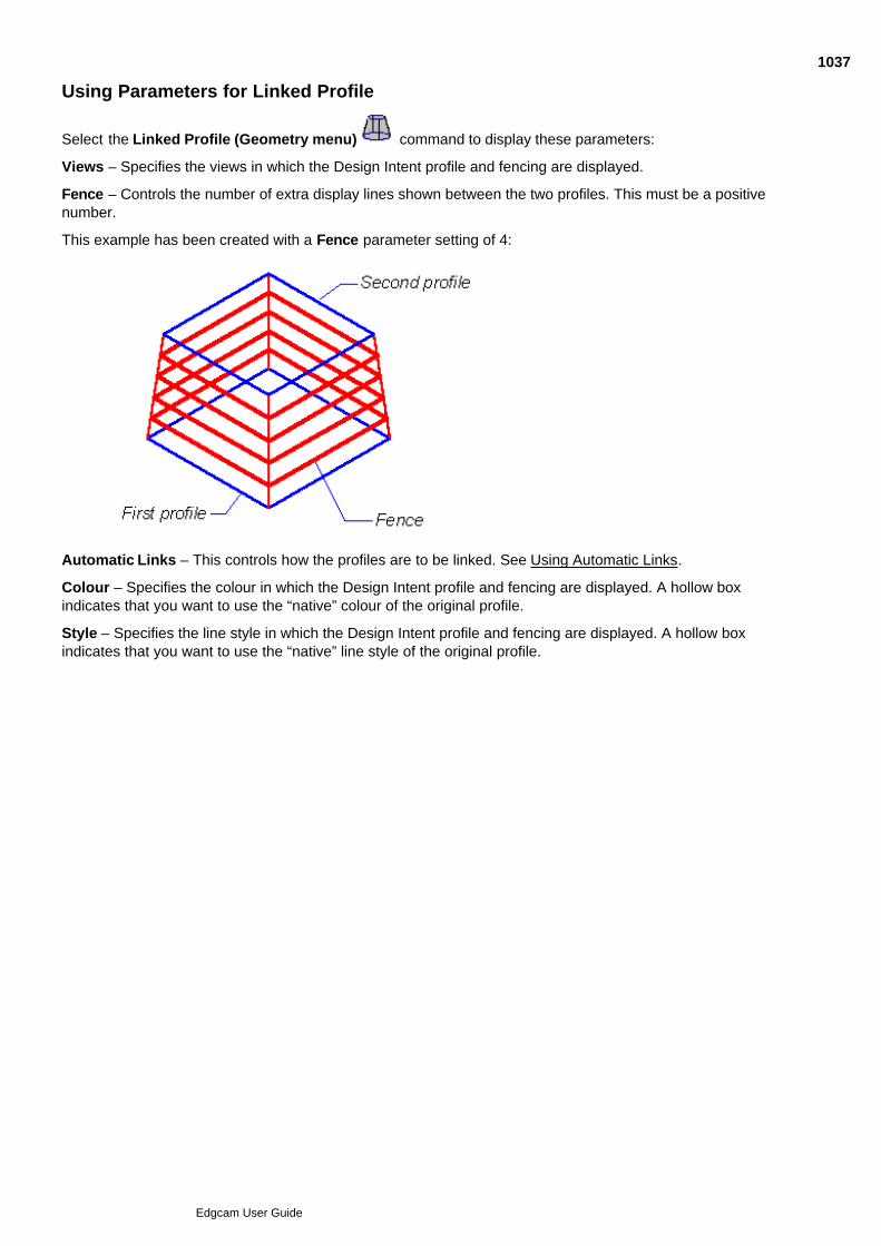
Using Parameters for Linked Profile
Select the Linked Profile (Geometry menu) command to display these parameters:
Views – Specifies the views in which the Design Intent profile and fencing are displayed.
Fence – Controls the number of extra display lines shown between the two profiles. This must be a positivenumber.
This example has been created with a Fence parameter setting of 4:
Automatic Links – This controls how the profiles are to be linked. See Using Automatic Links.
Colour – Specifies the colour in which the Design Intent profile and fencing are displayed. A hollow boxindicates that you want to use the “native” colour of the original profile.
Style – Specifies the line style in which the Design Intent profile and fencing are displayed. A hollow boxindicates that you want to use the “native” line style of the original profile.
1037
Edgcam User Guide
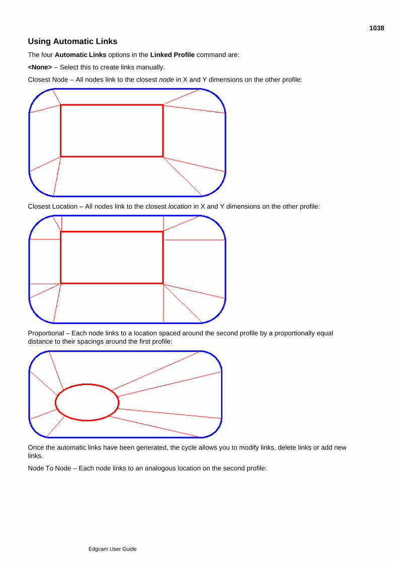
Using Automatic Links
The four Automatic Links options in the Linked Profile command are:
<None> – Select this to create links manually.
Closest Node – All nodes link to the closest node in X and Y dimensions on the other profile:
Closest Location – All nodes link to the closest location in X and Y dimensions on the other profile:
Proportional – Each node links to a location spaced around the second profile by a proportionally equaldistance to their spacings around the first profile:
Once the automatic links have been generated, the cycle allows you to modify links, delete links or add newlinks.
Node To Node – Each node links to an analogous location on the second profile:
1038
Edgcam User Guide
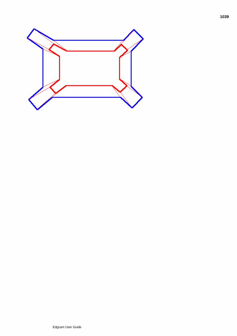
1039
Edgcam User Guide
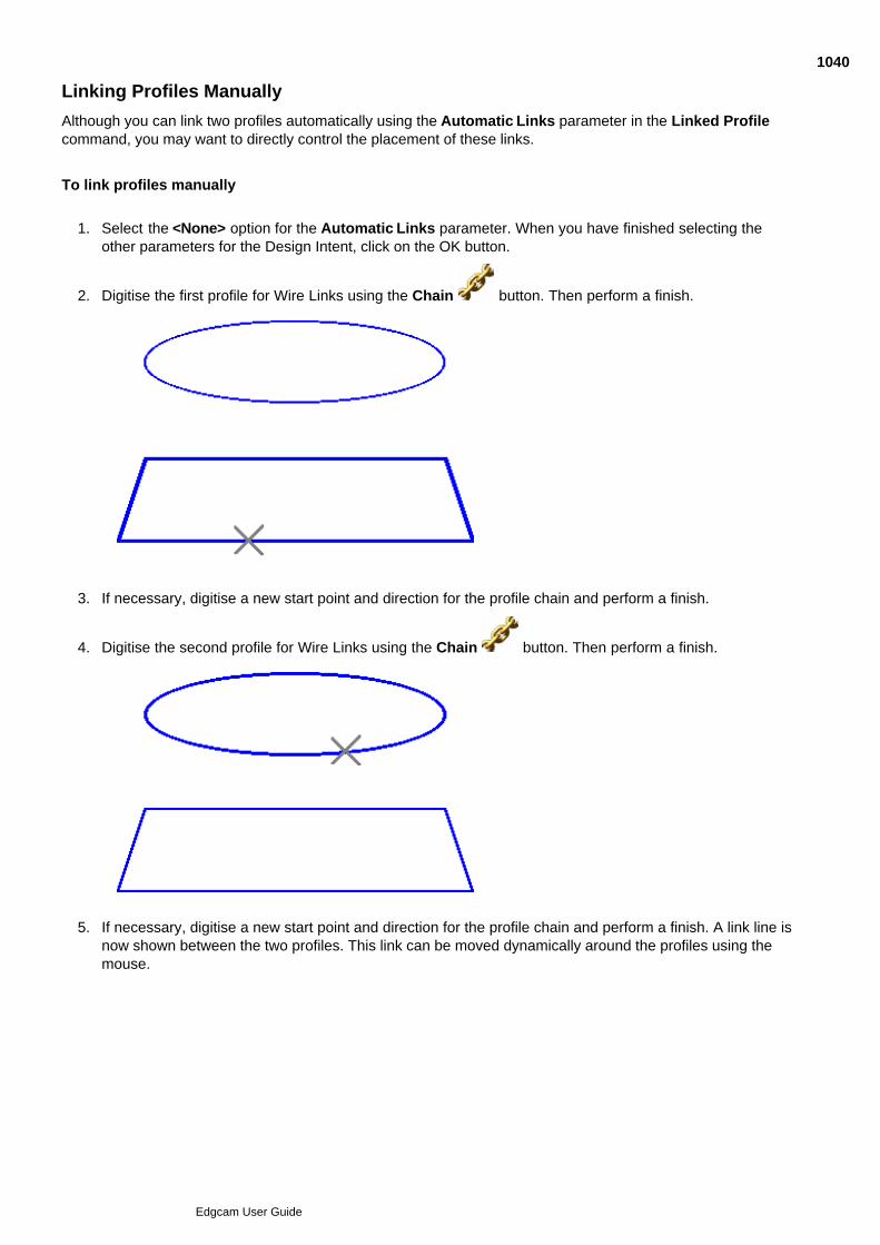
Linking Profiles Manually
Although you can link two profiles automatically using the Automatic Links parameter in the Linked Profilecommand, you may want to directly control the placement of these links.
To link profiles manually
Select the <None> option for the Automatic Links parameter. When you have finished selecting theother parameters for the Design Intent, click on the OK button.
1.
Digitise the first profile for Wire Links using the Chain button. Then perform a finish.2.
If necessary, digitise a new start point and direction for the profile chain and perform a finish.3.
Digitise the second profile for Wire Links using the Chain button. Then perform a finish.4.
If necessary, digitise a new start point and direction for the profile chain and perform a finish. A link line isnow shown between the two profiles. This link can be moved dynamically around the profiles using themouse.
5.
1040
Edgcam User Guide
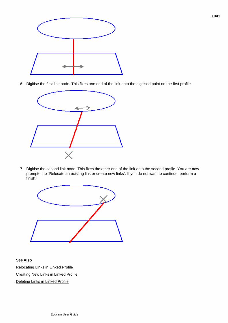
5.
Digitise the first link node. This fixes one end of the link onto the digitised point on the first profile.6.
Digitise the second link node. This fixes the other end of the link onto the second profile. You are nowprompted to “Relocate an existing link or create new links”. If you do not want to continue, perform afinish.
7.
See Also
Relocating Links in Linked Profile
Creating New Links in Linked Profile
Deleting Links in Linked Profile
1041
Edgcam User Guide

1042
Edgcam User Guide
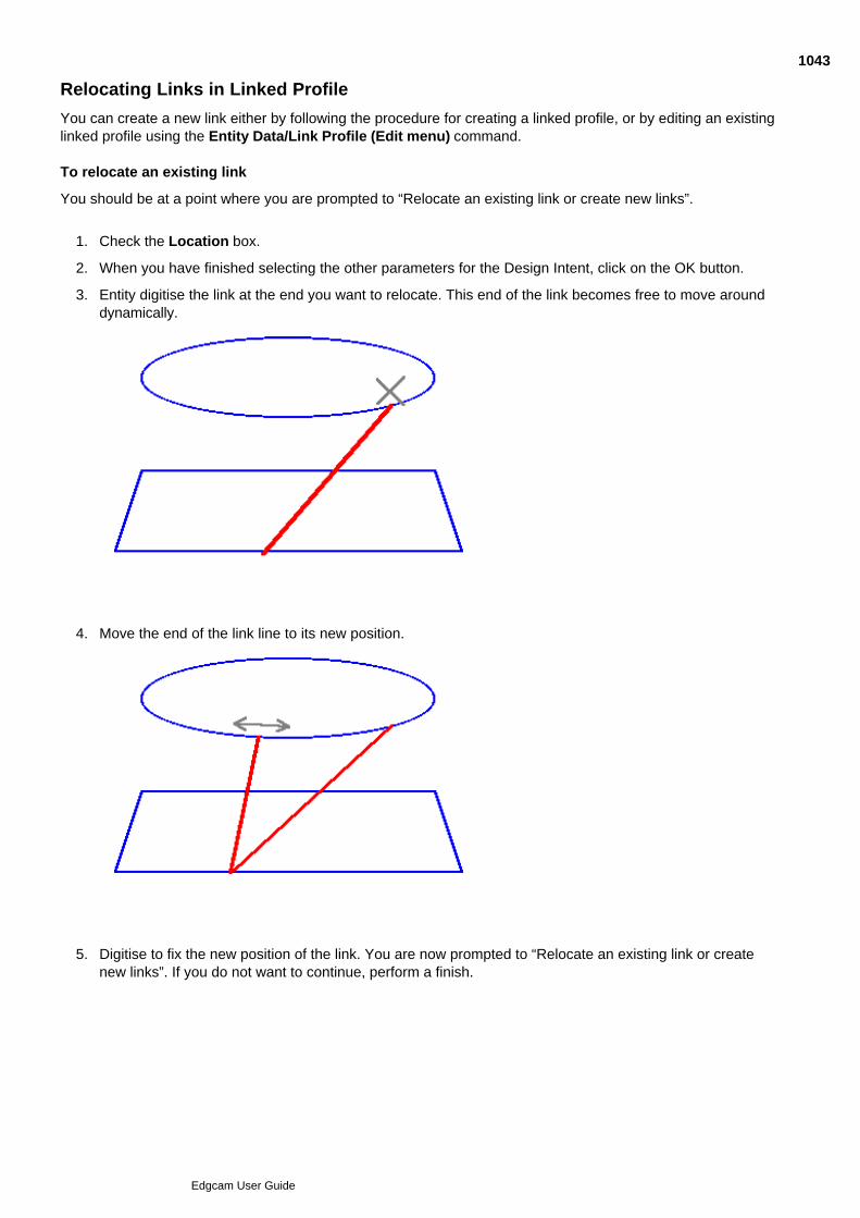
Relocating Links in Linked Profile
You can create a new link either by following the procedure for creating a linked profile, or by editing an existinglinked profile using the Entity Data/Link Profile (Edit menu) command. To relocate an existing link
You should be at a point where you are prompted to “Relocate an existing link or create new links”.
Check the Location box.1.
When you have finished selecting the other parameters for the Design Intent, click on the OK button.2.
Entity digitise the link at the end you want to relocate. This end of the link becomes free to move arounddynamically.
3.
Move the end of the link line to its new position.4.
Digitise to fix the new position of the link. You are now prompted to “Relocate an existing link or createnew links”. If you do not want to continue, perform a finish.
5.
1043
Edgcam User Guide
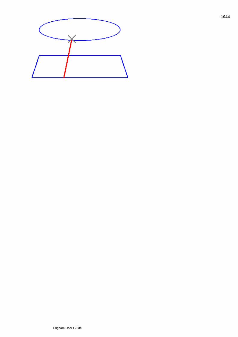
5.
1044
Edgcam User Guide
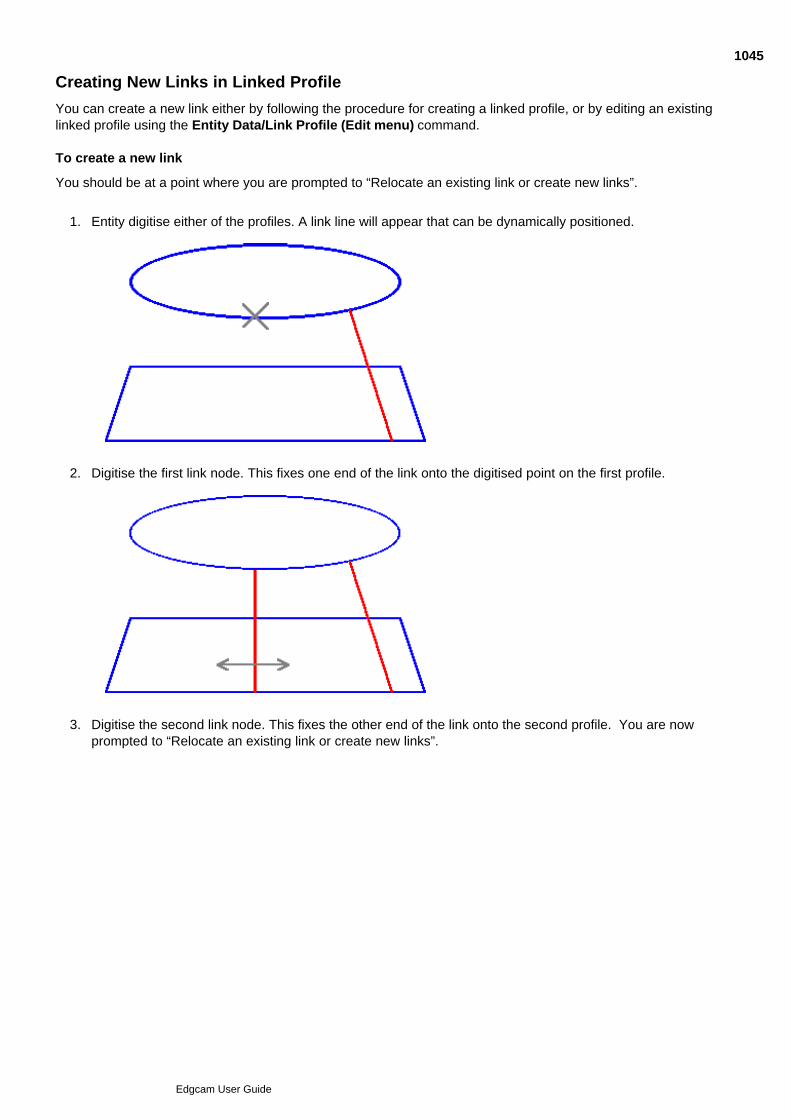
Creating New Links in Linked Profile
You can create a new link either by following the procedure for creating a linked profile, or by editing an existinglinked profile using the Entity Data/Link Profile (Edit menu) command. To create a new link
You should be at a point where you are prompted to “Relocate an existing link or create new links”.
Entity digitise either of the profiles. A link line will appear that can be dynamically positioned.1.
Digitise the first link node. This fixes one end of the link onto the digitised point on the first profile.2.
Digitise the second link node. This fixes the other end of the link onto the second profile. You are nowprompted to “Relocate an existing link or create new links”.
3.
1045
Edgcam User Guide
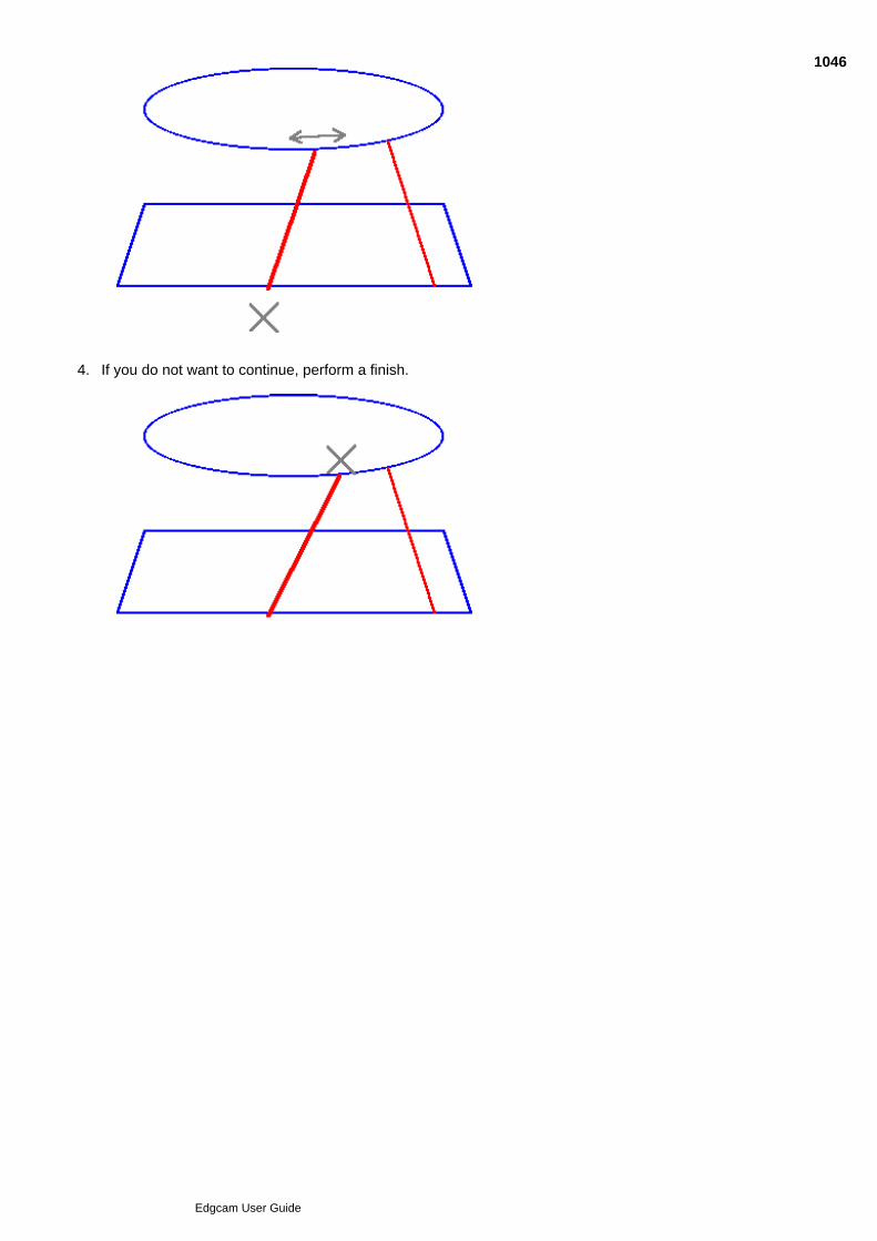
3.
If you do not want to continue, perform a finish.4.
1046
Edgcam User Guide

Deleting Links in Linked Profile
To delete a link
Entity digitise an existing link.1.
Select Escape .2.
Once all the links are in place, perform a finish.3.
1047
Edgcam User Guide
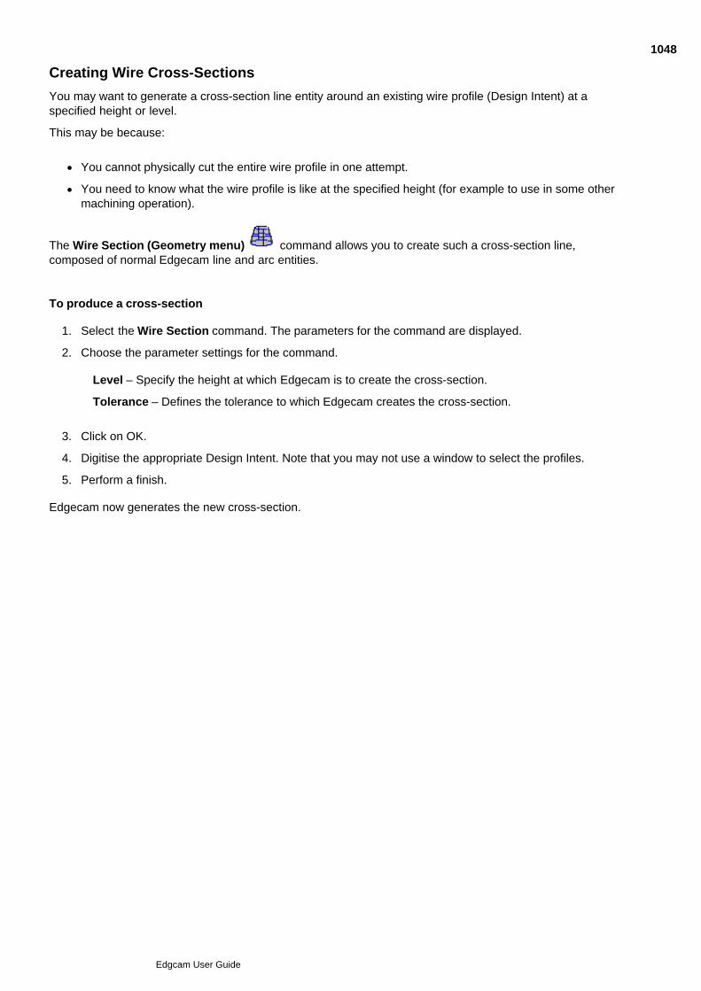
Creating Wire Cross-Sections
You may want to generate a cross-section line entity around an existing wire profile (Design Intent) at aspecified height or level.
This may be because:
You cannot physically cut the entire wire profile in one attempt.
You need to know what the wire profile is like at the specified height (for example to use in some othermachining operation).
The Wire Section (Geometry menu) command allows you to create such a cross-section line,composed of normal Edgecam line and arc entities.
To produce a cross-section
Select the Wire Section command. The parameters for the command are displayed.1.
Choose the parameter settings for the command.2.
Level – Specify the height at which Edgecam is to create the cross-section.
Tolerance – Defines the tolerance to which Edgecam creates the cross-section.
Click on OK.3.
Digitise the appropriate Design Intent. Note that you may not use a window to select the profiles.4.
Perform a finish.5.
Edgecam now generates the new cross-section.
1048
Edgcam User Guide

Editing the Design Intent
Use the Entity Data (Edit menu) commands to alter the parameters for an existing wire profile:
Editing Commands Notes
Apply to All Affects entire profile. Cannot alter links.
Individual Affects part of the profile. Cannot alter links.
Match Matches parameters of selected profile to that of target profile.Cannot alter links
Link Profile May be used to alter Linked Profiles, including relocating existingnodes or creating new nodes.
See Also
Editing Transformed Profiles
Editing Tapered Profiles
Editing Linked Profiles
1049
Edgcam User Guide

Editing Transformed Profiles
To change the parameters for an existing Transformed Profile
Select the Entity Data/Apply to All (Edit menu) command or the Entity Data/Individual (Edit menu)command.
1.
Digitise the appropriate wire profile (or part if using the Individual command).2.
Perform a finish. Edgecam displays the parameters for the command used to generate the profile.3.
Change these parameters as necessary.4.
Click on the OK button.5.
Edgecam now re-creates the Wire Profile using the new parameters.
1050
Edgcam User Guide
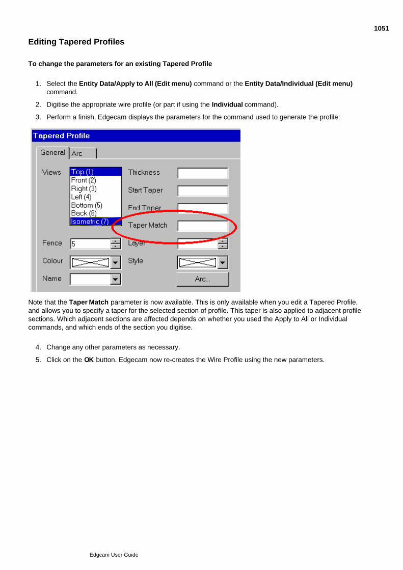
Editing Tapered Profiles
To change the parameters for an existing Tapered Profile
Select the Entity Data/Apply to All (Edit menu) command or the Entity Data/Individual (Edit menu)command.
1.
Digitise the appropriate wire profile (or part if using the Individual command).2.
Perform a finish. Edgecam displays the parameters for the command used to generate the profile:3.
Note that the Taper Match parameter is now available. This is only available when you edit a Tapered Profile,and allows you to specify a taper for the selected section of profile. This taper is also applied to adjacent profilesections. Which adjacent sections are affected depends on whether you used the Apply to All or Individualcommands, and which ends of the section you digitise.
Change any other parameters as necessary.4.
Click on the OK button. Edgecam now re-creates the Wire Profile using the new parameters.5.
1051
Edgcam User Guide
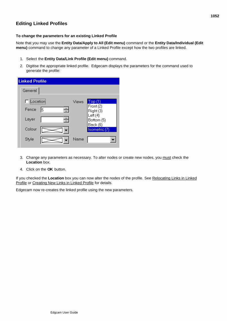
Editing Linked Profiles
To change the parameters for an existing Linked Profile
Note that you may use the Entity Data/Apply to All (Edit menu) command or the Entity Data/Individual (Editmenu) command to change any parameter of a Linked Profile except how the two profiles are linked.
Select the Entity Data/Link Profile (Edit menu) command.1.
Digitise the appropriate linked profile. Edgecam displays the parameters for the command used togenerate the profile:
2.
Change any parameters as necessary. To alter nodes or create new nodes, you must check theLocation box.
3.
Click on the OK button.4.
If you checked the Location box you can now alter the nodes of the profile. See Relocating Links in LinkedProfile or Creating New Links in Linked Profile for details.
Edgecam now re-creates the linked profile using the new parameters.
1052
Edgcam User Guide

Creating the Toolpath
Before you try this, you should already have created a Wire Profile.
Whichever method you used to create the profile, simply select the command Machine Design (Wire Cyclesmenu). This command uses whatever information is stored in the profile to generate the appropriate toolpaths.
When you the generated toolpaths are satisfactory, select the Generate Code (File menu) command togenerate the CNC code from the existing instruction list and toolpath information.
See Also
Selecting the Wire
Transforming the Toolpath
Machining the Design Intent
Checking the Cycle Time
Verifying the Toolpath
Cutting the Support Tag
1053
Edgcam User Guide

Selecting the Wire
Use the Select Wire (Wire Cycles menu) command to set the parameters for the Wire Machine. Thiscommand lets you define the wire thickness and height of the upper and lower guide to be used when youmachine the part.
Diameter – Specifies the diameter of the wire.
Colour – Specifies the colour of the wire and any positional moves.
Upper Guide* – Specifies the height of the upper guide above the workplane.
Lower Guide* – Specifies the height of the lower guide above the workplane.
These guide height values will only be used if the Code Generator is set to output at guide height.
* Note: Guide height values are only applied to longhand output. Code Generators working at guide heights
should have taper mode disabled and 4-axis circular moves should be converted to linear moves.
1054
Edgcam User Guide

Machining the Design Intent
The Machine Design (Wire Cycles menu) command generates a Wire Erosion toolpath using theselected Design Intent and command parameters.
To machine a wire profile
Select the Machine Design (Wire Cycles menu) command.1.
Select any appropriate parameters.2.
Click on the OK button.3.
Digitise the wire profile to machine.4.
Digitise the position for the start hole.5.
Any simulation of the machining now occurs.
See Also
Using Parameters for Machine Design
Specifying the Lead Parameters
1055
Edgcam User Guide
Using Parameters for Machine Design
The Machine Design (Wire Cycles menu) command displays these parameters under the General tab:
Lead tab – These parameters specify how the wire approaches and leaves the profile. See Specifying the LeadParameters.
Constant Cut – Check this box to only cut the profile in a specified direction. This is usually only possible if themachine tool can cut the wire and be re-threaded at the cycle start point.
Feedrate – Controls the rate at which the machine tool moves the wire in the XY/UV planes.
Offset – Adds an amount to the offset of the wire from the digitised profile (a value of zero gives a path which isthe wire radius from the digitised profile).
You may want to allow for the radial thickness of the wire when machining the profile.
Number of Passes – Specifies the number of passes the wire makes along the specified profile.
Support Tag – Specifies the length of the support tag to be left at the end of the cut. This stop retains anymaterial that may drop away. For information on how to remove this, see Cutting the Support Tag.
If you select <Digitise>, after digitising the start of the profile, you are prompted to make a free or an entitydigitise to define the end of the profile. A marker showing the end point appears and you can dynamically dragthis in the same way as for the start point. Once you fix the position with a digitise, the distance to the end ofthe profile is calculated and used as the Support Tag size.
Twizzle Radius – Specify the radius of any twizzle moves you want on the corners of the profile.
Tolerance – Defines the tolerance to which Edgecam generates the toolpath.
Overlap – Specifies the distance by which the wire cuts past the start point of the cycle. This is overridden byany value entered for the Support Tag parameter.
Compensation – Select between:
Pathtrace – Edgecam’s powerful tool offset calculation facility
Controller – The machine tool controller’s own compensation facility.
Radius Compensation – Used with Compensation (above) to define how the wire offset is to be applied (asviewed in the direction of travel):
None – No compensation is to be used.
Left – The compensation is to be applied to the left of the toolpath.
Right – The compensation is to be applied to the right of the toolpath.
Colour – Specifies the colour used for the profile. The Native option makes the generated geometry the samecolour as the selected entities.
1056
Edgcam User Guide
Specifying the Lead Parameters
The Lead tab in the Machine Design (Wire Cycles menu) command displays these parameters:
These parameters control how lead in and lead out moves are to be applied when machining the Design Intent.Note that the maximum value allowed for Angle In or Angle Out is 180 degrees. Any higher value entered forthese parameters will be taken to be 180 degrees.
How these parameters are applied is illustrated in this example of a lead in move (the parameters are thereforeAngle In, Radius In and Length In):
1057
Edgcam User Guide

About the 2D Cycles
Two cycles allow you to perform wire erosion on simple Edgecam geometry. These are:
2D Destruct (an area clearance cycle)
2D Profile ( a profiling cycle)
Note that these cycles only work:
On normal Edgecam geometry, not Design Intent profiles.
With Code Generator files that contain the 2D Destruct and 2D Profile macros.
These cycles do not automatically prompt you to specify start holes. See Generating Start Hole Positions fordetails.
1058
Edgcam User Guide
Using 2D Destruct
The 2D Destruct (Wire Cycles menu) command begins with a feed move from the current wire positionto the start point for the cycle. It then performs a concentric area clearance cycle from the centre of the area tothe boundary of a digitised XY closed profile.
You can digitise multiple profiles using this cycle. Any linking moves (where the wire is cut) are indicated by adashed line style.
The parameters for the cycle are:
Feedrate – Controls the rate at which the machine tool moves the wire in the XY/UV planes.
Offset – Adds an amount to the offset of the wire from the boundary profile left by the cycle (a value of zerogives a path which is the wire radius from the boundary profile).
You may want to allow for the radial thickness of the wire when machining the profile.
Stepover – Specify the percentage of the wire diameter as the stepover value. From this Edgecam calculatesthe distance to move out by on each consecutive destruct pass.
Note that this can produce unwanted results. If there are sharp internal corners, only values of 50(percent) or less are safe. For round holes, you can use values up to 100.
Feature Name – Specify the name given to the entities selected for the cycle.
Tolerance – Specify the interpolation tolerance of any curves you digitise to define the boundary profile.
1059
Edgcam User Guide

Using 2D Profile
The 2D Profile (Wire Cycles menu) command begins with a feed move from the current wire position tothe start point for the cycle. It then performs a single pass along the left or right of a digitised XY profile.
You can digitise multiple profiles using this cycle. Any linking moves (where the wire is cut) are indicated by adashed line style.
The parameters for the cycle are:
Feedrate – Controls the rate at which the machine tool moves the wire in the XY/UV planes.
Offset – Adds an amount to the offset of the wire from the boundary profile left by the cycle (a value of zerogives a path which is the wire radius from the boundary profile).
You may want to allow for the radial thickness of the wire when machining the profile.
Twizzle Radius – Specify the radius of any twizzle moves you want on the corners of the profile.
Tolerance – Specify the interpolation tolerance of any curves you digitise to define the profile.
Compensation – Select Control or Pathtrace to determine whether the geometry or the wire centre path isoutput.
Feature Name – Specify the name given to the entities selected for the cycle.
Lead tab – Allows you to specify the Lead parameters. See Specifying the Lead Parameters for details.
1060
Edgcam User Guide

Generating Start Hole Positions
The 2D Destruct and 2D Profile cycles do not automatically prompt you to specify start holes.
To create these holes you must return to Design mode using the Design button.
You can now select the Start Hole Positions (Geometry menu) command.
Once you execute the command, you are prompted to digitise a toolpath. Edgecam generates point entitiesalong the toolpath where there is a change from a Rapid to a Feed move. The entities are generated in thecurrent layer, colour and style.
There is only one parameter for this command:
Group – Check this box for all point entities created by the command to be collected into one group entity. Ifleft blank, individual point entities are created.
1061
Edgcam User Guide

Cutting the Support Tag
The Cut Support Tag (Wire Cycles menu) command allows you to cut through any material previouslydesignated as a support tag (also known as a 'glue stop'). The Support Tag parameter of the Machine Design(Wire Cycles menu) defines the length of the support tag.
Note that if you did not specify a Support Tag in the Machine Design cycle, you cannot use the Cut SupportTag command on the Design Intent profile.
The parameters for this cycle are similar to those for Machine Design. For more information, see UsingParameters for Machine Design.
Once you have entered the parameters, you are prompted to do as follows:
Digitise the toolpath.1.
Digitise a position for the start hole.2.
Digitise the start of the support tag. This last digitise is to determine which end of the support tag the wireshould start cutting, determining the direction of the cut.
3.
Perform a finish.4.
1062
Edgcam User Guide

Transforming the Toolpath
Transform Translate (Edit menu) – This command moves or copies a series of instructions one or more times(used where the same feature appears more than once in a component).
You may only translate the toolpath in the X and Y directions.
Note that only the toolpaths are altered by these commands - there is no alteration of the originaldesign geometry.
1063
Edgcam User Guide
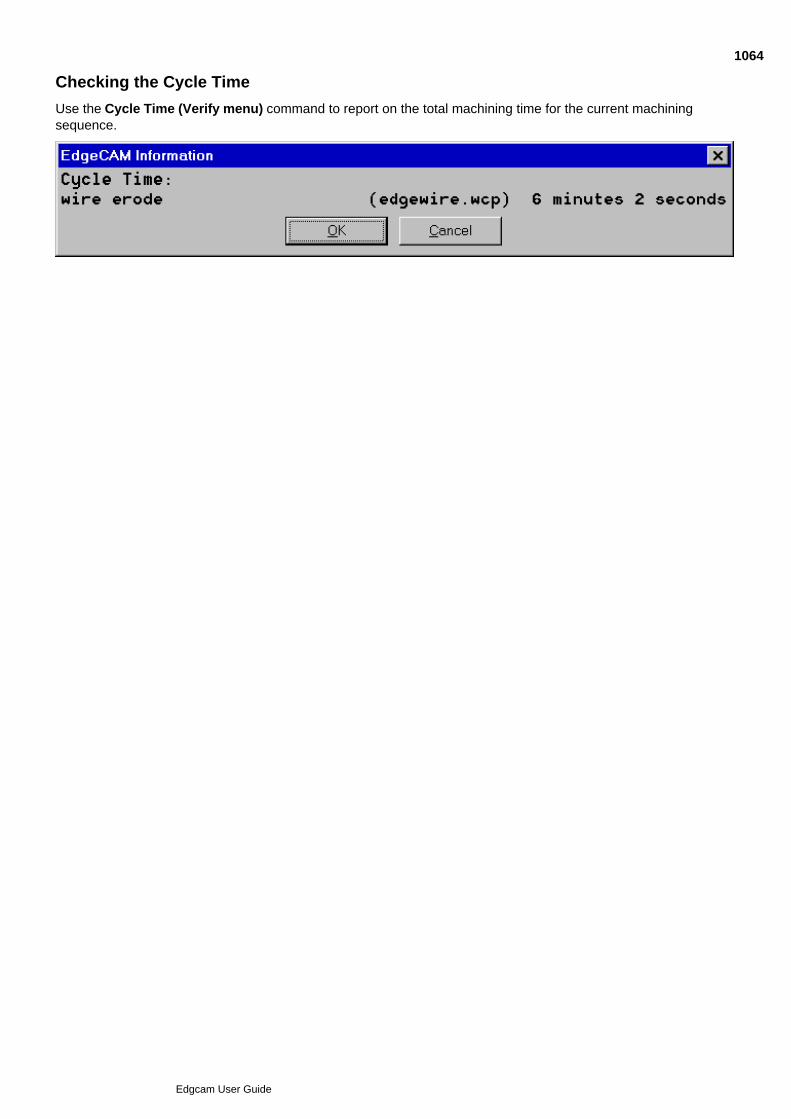
Checking the Cycle Time
Use the Cycle Time (Verify menu) command to report on the total machining time for the current machiningsequence.
1064
Edgcam User Guide
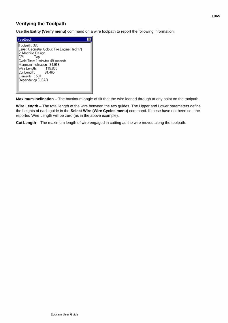
Verifying the Toolpath
Use the Entity (Verify menu) command on a wire toolpath to report the following information:
Maximum Inclination – The maximum angle of tilt that the wire leaned through at any point on the toolpath.
Wire Length – The total length of the wire between the two guides. The Upper and Lower parameters definethe heights of each guide in the Select Wire (Wire Cycles menu) command. If these have not been set, thereported Wire Length will be zero (as in the above example).
Cut Length – The maximum length of wire engaged in cutting as the wire moved along the toolpath.
1065
Edgcam User Guide
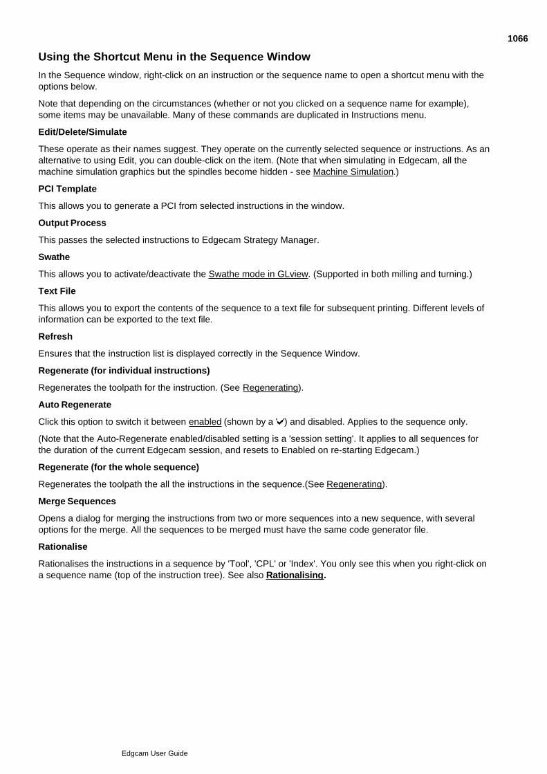
Using the Shortcut Menu in the Sequence Window
In the Sequence window, right-click on an instruction or the sequence name to open a shortcut menu with theoptions below.
Note that depending on the circumstances (whether or not you clicked on a sequence name for example),some items may be unavailable. Many of these commands are duplicated in Instructions menu.
Edit/Delete/Simulate
These operate as their names suggest. They operate on the currently selected sequence or instructions. As analternative to using Edit, you can double-click on the item. (Note that when simulating in Edgecam, all themachine simulation graphics but the spindles become hidden - see Machine Simulation.)
PCI Template
This allows you to generate a PCI from selected instructions in the window.
Output Process
This passes the selected instructions to Edgecam Strategy Manager.
Swathe
This allows you to activate/deactivate the Swathe mode in GLview. (Supported in both milling and turning.)
Text File
This allows you to export the contents of the sequence to a text file for subsequent printing. Different levels ofinformation can be exported to the text file.
Refresh
Ensures that the instruction list is displayed correctly in the Sequence Window.
Regenerate (for individual instructions)
Regenerates the toolpath for the instruction. (See Regenerating).
Auto Regenerate
Click this option to switch it between enabled (shown by a ' ') and disabled. Applies to the sequence only.
(Note that the Auto-Regenerate enabled/disabled setting is a 'session setting'. It applies to all sequences forthe duration of the current Edgecam session, and resets to Enabled on re-starting Edgecam.)
Regenerate (for the whole sequence)
Regenerates the toolpath the all the instructions in the sequence.(See Regenerating).
Merge Sequences
Opens a dialog for merging the instructions from two or more sequences into a new sequence, with severaloptions for the merge. All the sequences to be merged must have the same code generator file.
Rationalise
Rationalises the instructions in a sequence by 'Tool', 'CPL' or 'Index'. You only see this when you right-click ona sequence name (top of the instruction tree). See also Rationalising.
1066
Edgcam User Guide
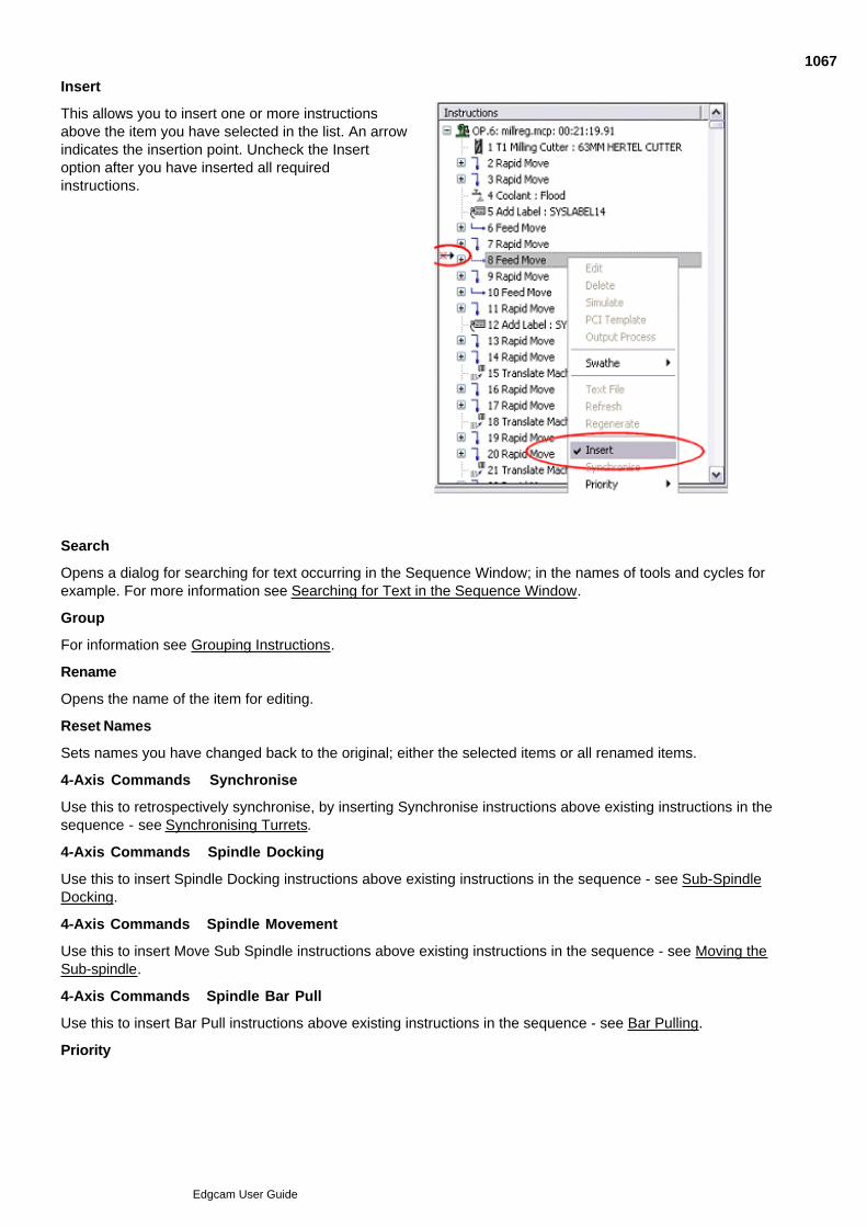
Insert
This allows you to insert one or more instructionsabove the item you have selected in the list. An arrowindicates the insertion point. Uncheck the Insertoption after you have inserted all requiredinstructions.
Search
Opens a dialog for searching for text occurring in the Sequence Window; in the names of tools and cycles forexample. For more information see Searching for Text in the Sequence Window.
Group
For information see Grouping Instructions.
Rename
Opens the name of the item for editing.
Reset Names
Sets names you have changed back to the original; either the selected items or all renamed items.
4-Axis Commands Synchronise
Use this to retrospectively synchronise, by inserting Synchronise instructions above existing instructions in thesequence - see Synchronising Turrets.
4-Axis Commands Spindle Docking
Use this to insert Spindle Docking instructions above existing instructions in the sequence - see Sub-SpindleDocking.
4-Axis Commands Spindle Movement
Use this to insert Move Sub Spindle instructions above existing instructions in the sequence - see Moving theSub-spindle.
4-Axis Commands Spindle Bar Pull
Use this to insert Bar Pull instructions above existing instructions in the sequence - see Bar Pulling.
Priority
1067
Edgcam User Guide

Sets the spindle priority. This might be needed after using Synchronise, for example.
Side by Side
This places each sequence in its own tab. The tab label acts as the sequence name (in that you can right-clickon it to display the shortcut menu for the sequence). This is in addition to the normal use of the tab label toswitch to the tab. Also, for twin turret machines, the Upper and Lower turrets are displayed as two columns ofinstructions placed next to each other.
Single Scroll Bar
This scrolls both the panes (in Side by Side view, one pane for each turret) using the same scroll bar.
1068
Edgcam User Guide

Editing Instructions in the Sequence Window
To move instructions, select one or more instructions in the list and hold down the left-hand mouse button todrag and drop the instruction(s) to a new position.
To copy use the same method but while simultaneously holding down the Ctrl key.
Note that you can only move or copy if the destination is in an active sequence. This means you can copy ormove within the active sequence, or from an inactive sequence to the active sequence.
In Side-by-Side view (where there is a separate tab for each sequence), to move between sequences you firstdrag onto the tab label for the destination sequence (still holding down the left mouse key). This switches youto that tab, and you can then move to the appropriate position within its instruction list. (Note that asterisks (*)indicate the active sequence's tab.)
To work with instructions using the menus
You can work with instructions using the options in the Instructions menu, and in the shortcut menu for theinstructions and sequences. Many of the options are duplicated between these menus. For details of theoptions see Using the Shortcut Menu in the Sequence Window.
Notes
Editing one or more sub-instructions within an Operation breaks the Operation down into its constituentcycles.
If you edit an Index (Move menu) command, all subsequent commands may be invalidated.
Once the instruction list has been changed, Edgecam recalculates the toolpath according to the newgeometry.
See Also
Combining Components and Sequences
1069
Edgcam User Guide

Combining Components and Sequences - Guidelines
When creating some tombstone multi-index machining, for example, you might want to build up the part byinserting other Edgecam parts, copying in the sequences from the other parts and then merging the sequencesand rationalising.
Here are some guidelines:
Create a 'base part' for the machine tool, containing the machine's basic set up and configuration. Createcommonly used fixtures, such as a machined cube. Create a sequence with these items correctlyspecified:- code generator, Home/Toolchange position, Initial Plane, Initial CPL and Machine Datumpoint. Save the base part for later re-use and create a backup copy.
1.
On the fixture (machined cube) make sure CPLs are created representing suitable location (mounting)positions. On the parts to be inserted make sure there are corresponding CPLs, so that when the twoCPLs are mated on merging, the inserted parts are mounted correctly.
2.
Use File menu Insert Component, opting to 'Insert Sequences' from the inserted part, and using'Name Prefix' to label the inserted component's CPLs - see Inserting a Part as a Component.
3.
Carry on to merge the original and inserted sequences and perhaps rationalise the resulting sequence4.
See also:
Notes on Inserting and Merging
1070
Edgcam User Guide
Notes on Inserting and Merging Sequences
Realignment of Toolpaths
Some toolpaths may move relative to their geometry, on being inserted. This would happen if the cyclehad parameters not linked to geometry, such as free digitises and lace angles (which are specified in the'working CPL' at the time). This is most likely to occur when components are inserted with a rotation.
To avoid this base the cycles as much as possible on entity digitises, to lock them to the geometry.
Post Processors
You can only merge sequences that have the same code generator.
Safe Indexing
Index moves must be performed with the tool at a safe height in all parts. Check this after the merge.
Indexes in parts for insertion should 'Position to Name' rather than 'Position to Angle'.
Component Prefixes
Use 'Name Prefix' in the Insert Component dialog, to aid identification (CPLs, layers, sequences and soon are automatically renamed with appended number's but this can be confusing).
Rotary Milling
The Insert Component and Merge Sequence commands are not supported in rotary milling.
Wire Erosion
Merging Sequences is restricted to the milling and turning environment and will not appear in the wiremanufacture mode.
PCI
PCI command recording and playback is not supported for merge sequences.
Turning
Datum shift is not supported by Edgecam for turning parts, so all inserted components with sequencesmust use the same target CPL.
1071
Edgcam User Guide

Merging Sequences
Only available in the milling and turning environment. Not supported by rotary milling.
Use Instructions menu Merge Sequences to open the dialog below.
See also Combining Components and Sequences.
1072
Edgcam User Guide

Rationalising Sequences
Use Instructions menu Rationalise to open the dialog detailed below (you can also access thishelp by clicking the Help button in the dialog).
1073
Edgcam User Guide
Using Instructions Menu Commands
Several commands in the Instructions menu allow you to alter existing commands in the current instructionlist.
Notes
Only commands that are included in the instruction list can be edited, moved or deleted.
If you edit an Index (Move menu) command, all subsequent commands may be invalidated.
Editing one or more sub-instructions within an Operation breaks the Operation down into its constituentcycles.
Once the instruction list has been changed, Edgecam recalculates the toolpath according to the newgeometry.
The Instructions menu commands are:
Edit – Change a command’s parameters and any related co-ordinate input. If you have deleted any entities,you must respecify the entities required by the machining cycle. You can select more than one command at thesame time. Aborting or Escaping at this stage deletes the cycle.
Edit Screensnap – Change a command’s parameters and any related co-ordinate input by digitising theappropriate toolpath.
Insert – On/off toggle. When on, it allows a new instruction(s) to be inserted.
Move – Move a command’s position within the list. You may have to create commands out of sequence, butMove allows you to correct the order of events. You can select more than one command at the same time.
An example of this is when drilling a start hole for roughing. By drilling the hole after the Roughing cycle hasbeen created you know exactly where to position the hole. You can then move the instructions for the hole tobefore the cycle.
Copy – Duplicate a command at another location in the instruction list.
Delete – Remove a command from the instruction list. You can select more than one command at the sametime.
Regenerate – Regenerates the machining sequence from the selected instruction onwards.
Regenerate Screensnap – Regenerates the machining sequence from the digitised toolpath onwards.
Synchronise – (Only used for Four Axis Turning) Inserts a turret synchronisation command into the instructionlist.
View – Displays the machining sequence from the selected instruction onwards, including parameter input andscreen digitises.
View Screensnap – Displays the machining sequence from the digitised toolpath onwards, includingparameter input and screen digitises.
Simulate - Displays a tool simulation from the selected instruction onwards.
Simulate Screensnap – Displays a tool simulation from the digitised toolpath onwards.
Operation – All subsequent instructions are grouped under an Operation name, until you select the Operationcommand again.
Rationalise – (Milling environment only) Enables you to re-order the instructions in a single sequence torationalise the NC file by one or more criteria. Choose between sorting by Tool, CPL or Index. Also seeRationalise.
Merge Sequences - (Milling and turning environment) Allows you to merge two or more sequences into one by
1074
Edgcam User Guide

appending the instructions in the second and subsequent sequences to those in the current sequence.
Feature Check – Checks machining instructions for valid features. When you select the command you will beprompted to either pick a feature or finish without any selection to check the entire sequence. When one ormore features are selected the feedback window will list all the cycles and operations that use the feature(s) astheir entity data. When you finish without any selection the entire sequence will be checked for cycles oroperations that contain invalid entity data and the results displayed in the feedback window.
See Also
Choosing the Editing Options
Selecting from the Instruction List
Editing Instructions in the Sequence Window
1075
Edgcam User Guide
Choosing the Editing Options
When using Instructions menu Edit, to edit instructions, you first see a dialog for specifying the options youwant to apply to the edit:
Screen Snap – Check this box to select the command by digitising the appropriate toolpath, rather than byselecting the command from the instruction list.
Operations – Check this box to list only those operations defined in the current machining sequence, ratherthan all commands in the instruction list. Operations can be defined with the Operation (Instructions menu)command.
Global – Check this box to alter the Feeds, Speeds and Depth... parameters for all selected commands.
Redraw – Check this box to redraw the screen after you have edited the instruction list.
Disable Automatic Regeneration – Check this box to only regenerate the selected instructions. Edgecamdefaults to regenerating all subsequent instructions, which you might consider unnecessary and time-consuming if you were simply changing the colour of the toolpath.
Caution – To avoid invalid results you should regenerate the toolpath before saving or generating CNCcode.
Click OK when you want to proceed.
Note that you can also edit instructions using the shortcut menu in the Sequence Window.
1076
Edgcam User Guide
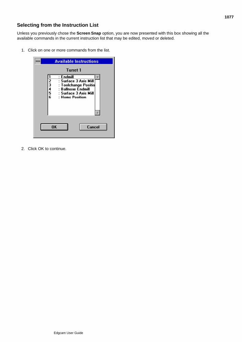
Selecting from the Instruction List
Unless you previously chose the Screen Snap option, you are now presented with this box showing all theavailable commands in the current instruction list that may be edited, moved or deleted.
Click on one or more commands from the list.1.
Click OK to continue.2.
1077
Edgcam User Guide

Respecifying Co-ordinate Input
Once you have selected all the instructions that you want to edit, you are presented with the dialog box foreach command in turn.
If a command needs you to input co-ordinate information, a new parameter is shown on the dialog -Coord Input.
Select one or more of the options. You can re-specify the co-ordinate information for each of theseaspects of the cycle after you click OK for the cycle parameter input dialog box.
Coord Input may appear instead as follows:
Check this box to respecify the co-ordinates required by Edgecam. Once you click on the OK buttonyou are prompted to enter this information in the usual manner for the particular command.
1078
Edgcam User Guide

Editing the Toolpath
Please note that these options are only available in the milling and turning environment
Several commands allow you to edit the toolpath itself. These can be selected from Toolpath (Edit menu):
Section - Changes a toolpath section.
Split - Breaks up a toolpath.
Delete - Deletes a toolpath section.
Note that once a toolpath has been edited using one of these commands, it is no longer a normal machininginstruction and cannot be edited or regenerated.
Toolpaths that have been edited will be shown with an appropriate comment after the command name in theinstruction list.
1079
Edgcam User Guide

Deleting a Section of a Toolpath
The command Toolpath Delete (Edit menu) lets you remove part of a toolpath between two selected points.The system then creates a linear tool move to link the two parts of the toolpath.
Link Control – (Milling only) Specifies how the link moves are to be created. Select Shortest to create a singlelinear move. Select Retract to create a vertical move to the Retract plane (defined below) before adding a linkmove.
Depth Parameters – (Milling only) Specifies the Clearance and Retract depth levels used by the system togenerate the link moves.
Screen Snap – Check this box to select a toolpath from the screen rather than a command from the instructionlist.
1080
Edgcam User Guide

Editing a Section of a Toolpath
The command Toolpath Section (Edit menu) lets you change part of a toolpath between two selected points.
Location – Check this box to move a node on the toolpath. If you reposition an arc move, it will change into alinear move.
Feedrate – Specify the tool feedrate in the workplane for the selected part of the toolpath.
Plunge Feed – (Milling only) Specify the vertical tool feedrate (into and out of the workplane) for the selectedpart of the toolpath.
Speed – Specify the spindle speed to be used during the selected part of the toolpath.
Rapid – Check this box to change the selected part of the toolpath to all rapid moves.
Screen Snap – Check this box to select the toolpath from the screen rather than from the instruction list.
1081
Edgcam User Guide

Splitting a Toolpath
The command Toolpath Split (Edit menu) lets you break a toolpath at a selected point to produce twoseparate toolpaths. This lets you insert new commands between the two toolpaths.
Screen Snap – Check this box to select a toolpath from the screen rather than a command from the instructionlist. The toolpath will then be broken at the point nearest to the digitised point on the screen.
1082
Edgcam User Guide
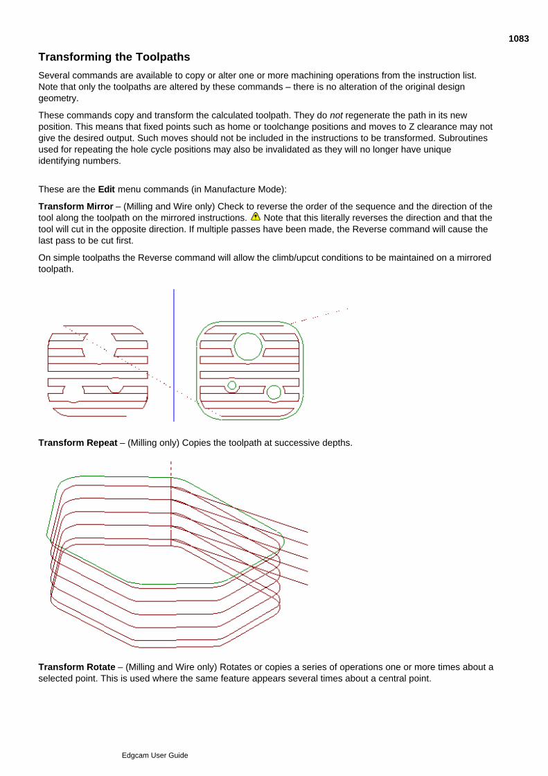
Transforming the Toolpaths
Several commands are available to copy or alter one or more machining operations from the instruction list.Note that only the toolpaths are altered by these commands – there is no alteration of the original designgeometry.
These commands copy and transform the calculated toolpath. They do not regenerate the path in its newposition. This means that fixed points such as home or toolchange positions and moves to Z clearance may notgive the desired output. Such moves should not be included in the instructions to be transformed. Subroutinesused for repeating the hole cycle positions may also be invalidated as they will no longer have uniqueidentifying numbers.
These are the Edit menu commands (in Manufacture Mode):
Transform Mirror – (Milling and Wire only) Check to reverse the order of the sequence and the direction of thetool along the toolpath on the mirrored instructions. Note that this literally reverses the direction and that thetool will cut in the opposite direction. If multiple passes have been made, the Reverse command will cause thelast pass to be cut first.
On simple toolpaths the Reverse command will allow the climb/upcut conditions to be maintained on a mirroredtoolpath.
Transform Repeat – (Milling only) Copies the toolpath at successive depths.
Transform Rotate – (Milling and Wire only) Rotates or copies a series of operations one or more times about aselected point. This is used where the same feature appears several times about a central point.
1083
Edgcam User Guide
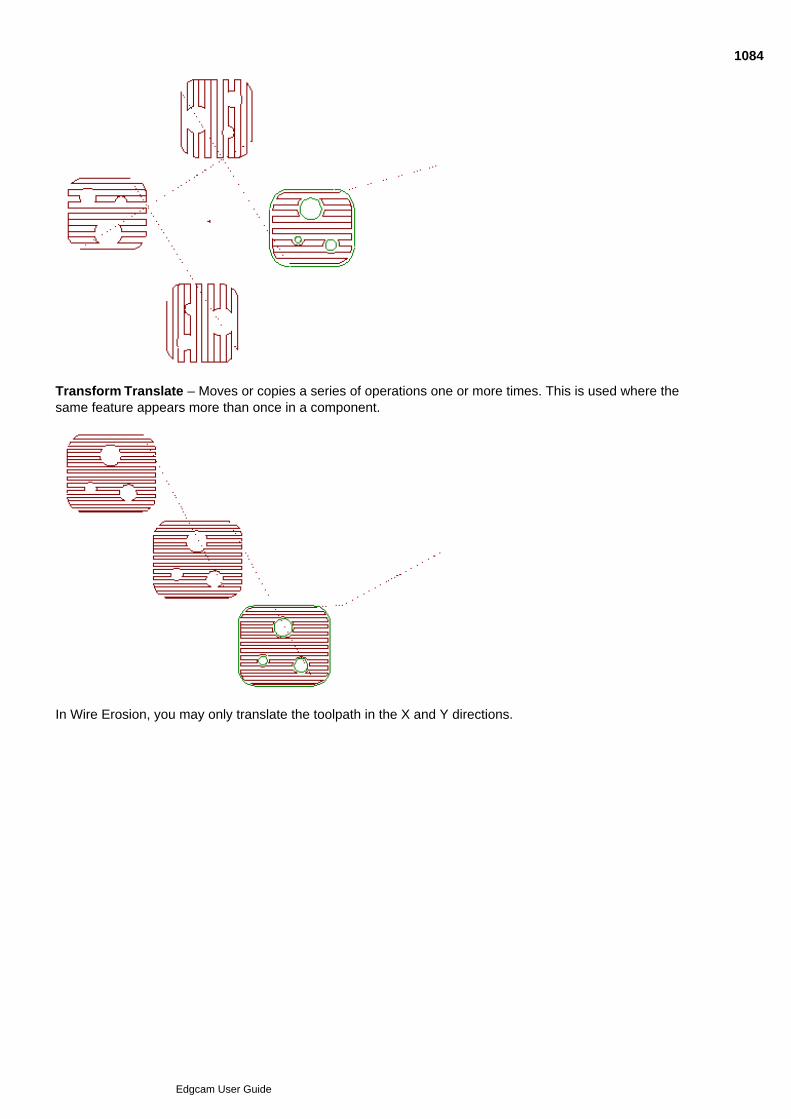
Transform Translate – Moves or copies a series of operations one or more times. This is used where thesame feature appears more than once in a component.
In Wire Erosion, you may only translate the toolpath in the X and Y directions.
1084
Edgcam User Guide

Using Matrix Mode
Only available in the milling environment
Matrix Mode lets you repeat an operation or series of operations at regular intervals, specifying the number ofrows and columns you need in your grid or matrix.
Edgecam always displays the selected geometry in the bottom left hand corner of the Matrix. The variouselements of the matrix are machined starting from the bottom left hand corner by default. However, when youselect a tool, the Quadrant list box lets you start from the other corners of the Matrix. (Note that the Quadrantparameter must have been enabled in your code generator for this to work.)
Matrix Mode Start (Edit menu) is used before the sequence of machining commands that are to be matrixed.
You now perform a normal sequence of toolchanges and machining cycles on the geometry as a singlepart.
Matrix Mode Finish (Edit menu) is used after you have finished entering the sequence of commands that areto be matrixed.
Each Matrix Mode Start must be completed with a Matrix Mode Finish command.
Note that the Mode (View menu) command contains a ‘Matrix’ check box that allows you to display or hide theMatrixed toolpath.
In this example, a Lacing area clearance toolpath has been created after a Matrix Mode Start.
On selecting the Matrix Mode Finish command, the Lacing toolpath is repeated in a grid according to theparameters specified in the Matrix Mode Start command.
Repeats – Specify the number of cells in the matrix in the X and Y direction.
Fret – Specify the number of Border widths (Double or Single) separating each cell in the matrix.
Border – Specify the border spacing in part units in X and Y.
Length – Specify the distance between each cell in the matrix in X and Y.
Dead Zones – Allows you to specify areas that can be used by clamps or fixturing. Define the dead zones bynominating two sides of the matrix rectangle and a distance in from the edge.
This example has X Repeats=5 and Y Repeats=4, and a Dead Zone along the bottom right of the matrix:
Direction – Specifies which cell is to be machined after the first cell. Select between Row or Column. Columnforces the tool to move to a cell in the Y direction and Row (the default) forces the tool to move to a cell in theX direction.
Lace Cut – Deselect to move the tool in the same direction along each row or column. The default setting ofthe checked box moves the tool to the next cell with the shortest possible movement.
Subroutines – Select Pathtrace to avoid using subroutines when generating CNC code from this matrixedtoolpath. The default setting of Controller will use subroutines where available.
Define Layout – Select to ignore the Direction modifier and specify exactly in which order the individual cellsare to be machined. The system displays a diagram of the cells in the matrix. Select each cell in the order youwant the cells machined in. As each cell is selected, it is given a number to show its position in the sequence.
1085
Edgcam User Guide
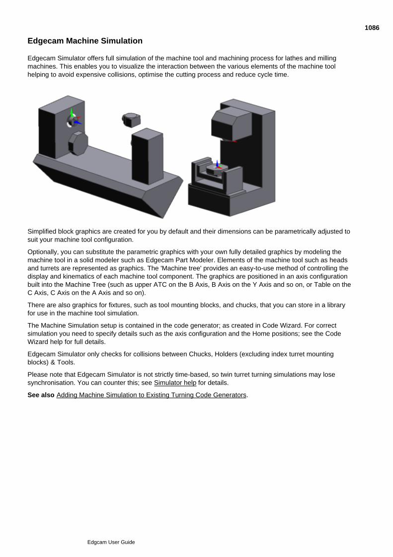
Edgecam Machine Simulation
Edgecam Simulator offers full simulation of the machine tool and machining process for lathes and millingmachines. This enables you to visualize the interaction between the various elements of the machine toolhelping to avoid expensive collisions, optimise the cutting process and reduce cycle time.
Simplified block graphics are created for you by default and their dimensions can be parametrically adjusted tosuit your machine tool configuration.
Optionally, you can substitute the parametric graphics with your own fully detailed graphics by modeling themachine tool in a solid modeler such as Edgecam Part Modeler. Elements of the machine tool such as headsand turrets are represented as graphics. The 'Machine tree' provides an easy-to-use method of controlling thedisplay and kinematics of each machine tool component. The graphics are positioned in an axis configurationbuilt into the Machine Tree (such as upper ATC on the B Axis, B Axis on the Y Axis and so on, or Table on theC Axis, C Axis on the A Axis and so on).
There are also graphics for fixtures, such as tool mounting blocks, and chucks, that you can store in a libraryfor use in the machine tool simulation.
The Machine Simulation setup is contained in the code generator; as created in Code Wizard. For correctsimulation you need to specify details such as the axis configuration and the Home positions; see the CodeWizard help for full details.
Edgecam Simulator only checks for collisions between Chucks, Holders (excluding index turret mountingblocks) & Tools.
Please note that Edgecam Simulator is not strictly time-based, so twin turret turning simulations may losesynchronisation. You can counter this; see Simulator help for details.
See also Adding Machine Simulation to Existing Turning Code Generators.
1086
Edgcam User Guide
Using Machine Simulation - Turning
Before starting to set up and use Machine Tool Simulation, you might want to work through the Machine ToolSimulation tutorials.
Here are the key stages in using Machine Tool Simulation:
Create part geometry as normal, in Design Mode.1.
Switch to Manufacture Mode, which initiates creating a machining sequence. In the Machining Sequencedialog select an appropriate code generator (that is a code generator that has been set up for machinesimulation in Code Wizard).
2.
Still In the Machining Sequence dialog, position the machine tool graphical representation.
See more details...
3.
Show or hide the machine tool graphics (Base, ATC and so on) as desired. (We recommend you hide thegraphics after positioning the machine, for an unobstructed view of the part. You would next show thegraphics at the simulation stage.)
See more details...
4.
If required, change the chuck parameters; change the Inner Jaw diameter to so that the jaws appearclamped around your part for example.
See more details...
Alternatively mount a different chuck.
See more details...
5.
Set the tool gauge distances. These are crucial as they determine how far the tool projects from itsmounting block, for example on an Index Turret. If no tool gauge distances are specified the tool tip ispositioned exactly at the tool setting position, as set in the code wizard. Therefore if no gauge values areset the tool is likely to be simulated fully buried in the block.
See more details...
6.
Optionally set up a job (kit of tools) for an indexing turret. If you have a kit where each tool has beenassigned a position around the turret and appropriate gauge distances set, at any time you can specifythe job in the Machine Sequence dialog to quickly populate the turret with tools.
You can create a toolkit independently from Edgecam in Toolkit Assistant.
Alternatively you can set up the turret, and copy the information to a new toolkit, within Edgecam.
See how to do this...
7.
Machine the part as required.
See more details (on moving the sub-spindle)...
8.
Optionally, simulate in Edgecam. This does not show the full machine graphics, as any visible graphics(apart from the spindles) become hidden. You might need to re-display the graphics as described in Step4 above.
9.
Open Simulator and show all the machine graphics; see Step 4 above (the same facilities for controllingmachine tool graphics are shown in Edgecam Simulator, as well as in Edgecam). Run the simulation andvisually check for collisions.
10.
1087
Edgcam User Guide
Using Machine Simulation - Milling
Here are the key stages in using Machine Tool Simulation when milling:
Create part geometry as normal, in Design Mode.1.
Switch to Manufacture Mode, which initiates creating a machining sequence. In the Machining Sequencedialog select an appropriate code generator (that is a code generator that has been set up for machinesimulation in Code Wizard).
2.
Still In the Machining Sequence dialog, position the machine tool.
See more details...
3.
If your Tool Change position is different to your Tool Home position, you will need to edit this. Click on M-Functions Machine Parameters to open the 'editing version' of the Machining Sequence dialog, andedit the settings in Tool Change tab. (Note that the Tool Home tab settings are unavailable, as thisposition is set within code generators that support Machine Simulation.)
4.
Show or hide the machine tool graphics (Base, Head, Tables and so on) as desired. (We recommendyou hide the graphics after positioning the machine, for an unobstructed view of the part. You would nextshow the machine graphics in Simulator.)
See more details...
5.
If required, change the chuck parameters; change the Inner Jaw diameter to so that the jaws appearclamped around your part for example.
6.
When you come to selecting a tool, in the Loading tab of the toolchange dialog, specify the 'Z Gauge'distance to determine how far the tool projects from the spindle. (Otherwise tool tip will be positioned atthe tool setting position, as configured into the code generator by Code Wizard, and subsequent machinesimulation will be incorrect.)
See more details...
7.
Machine the part as required.8.
Optionally, simulate in Edgecam. This does not show the full machine graphics, as any visible graphics(apart from the fixtures) become hidden. You might need to re-display the graphics after the simulationas described in Step 5 above.
9.
Open Simulator and show all the machine graphics; see Step 5 above (the same facilities for controllingmachine tool graphics are shown in Edgecam Simulator, as well as in Edgecam). Run the simulation andvisually check for collisions.
10.
After performing some machining and simulating it might be apparent that you need to move the partwithin the machine, by editing the mating positions.
The changes will cause the machine datum to move, and the sequence will regenerate. The moves toTool Change and Tool Home, and the rotary tool paths will be automatically updated.
See more details...
11.
1088
Edgcam User Guide

Using the Machine Tree
In both Edgecam and Simulator you use the Machine Tree (window) in combination with the Properties Windowto set the properties of the Machine Tool Simulation graphics.
You can, for example:
Set the visibility of graphics representing turrets, chucks and so on. (You can also use buttons for settingthe visibility of the whole machine, or particular graphics types, (see more details...)
Adjust the chuck jaws so they appear clamped round the part (Chuck graphic's 'Jaw Diameter' property).
In Edgecam (not Simulator) you can mount alternative chucks and tool mounting blocks (for example)from the Fixtures Tree .
Note that on loading a part, Edgecam refreshes some of its stored Machine Tree setup information from thecode generator. Usually your overrides will be kept, but there is a possibility that your changes in the MachineTree and Fixtures Tree will be lost - changes to graphics' translucency for example. (Your changes willdefinitely be lost if you use the 'Reload Machine' shortcut menu option.)
There are also some properties that are shown in the Machine Tree for information only, such as turret graphicdimensions. To change these machine properties you need to use Code Wizard, recompiling the codegenerator - see Changing the Setup.
Too use the tree:
Make sure the Machine Tree and Properties windows are shown.1.
Then, as necessary to show the branch:
Click to expand a branch and show its contents.
Click to contract a branch and hide its contents.
2.
Then select the branch and make the changes:3.
1089
Edgcam User Guide
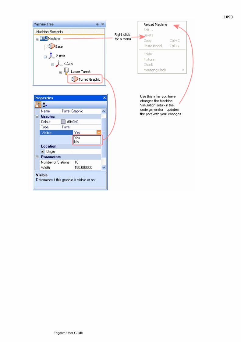
3.1090
Edgcam User Guide
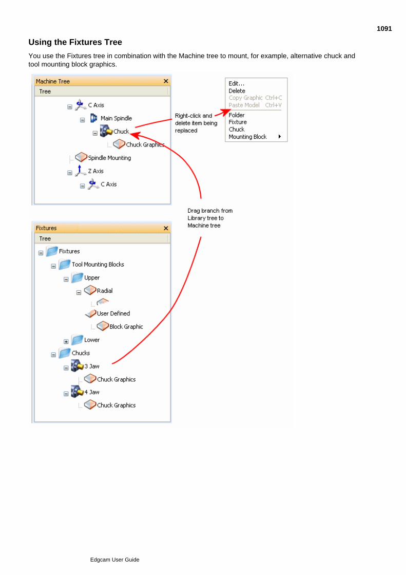
Using the Fixtures Tree
You use the Fixtures tree in combination with the Machine tree to mount, for example, alternative chuck andtool mounting block graphics.
1091
Edgcam User Guide
Changing the Machine Simulation Setup
In Edgecam you can change the aspects of the Machine Simulation setup that relate to the particular currentjob. For example:
The properties of graphics such as colours, dimensions and so on.
Chuck dimension parameters.
The spindle separation, using Edit Lathe Setup (you will potentially need to change tool gauge values,reorganise tooling, review synchronisation and so on).
In Edgecam you cannot change the properties of the machine tool, such as the turret diameter, as these mustreflect the physical reality of the machine.
To make these types of changes you need to make changes to the code generator (note that you cannotchange the fundamental kinematics - you cannot delete an axis for example):
Start Code Wizard.1.
Open the Code Generator Document for the code generator (this has the same name as the codegenerator, but with a '.CGD' extension).
2.
Change the machine simulation setup; using the Machine tree and Properties window, for example.3.
Save the CGD and re-compile the code generator.4.
Switch to Edgecam, right-click in the Machine Tree window and in the shortcut menu click ReloadMachine.
Note that you will lose any changes you may have made in the Machine Tree and the Fixtures Tree.
5.
For more details see the code wizard help.
1092
Edgcam User Guide

Generating CNC Code
Use File menu Generate Code to open the dialog below.
(you can also access this help by clicking the Help button in the dialog):
1093
Edgcam User Guide

About CNC Filenames
When a milling or single turret turning sequence is generated, the CNC filename is generated to the followingformat:
CNC file - example.nc
Setup file (optional) - example-set.nc
When a single .nc file is generated, there is no ‘-1’ included in the name. This clarifies that the file is for a singleturret machine. You can specify an extension other than ‘.nc’.
When a multiple turret turning sequence is generated, the CNC filename is generated to the following format:
1st CNC file - example-1.nc
2nd CNC file - example-2.nc
Setup file (optional) - example-set.nc
The Edgecam Editor and Communications modules interpret and use long filenames generated from Edgecam(or any application) when running on a Windows NT installation.
Note, however, that long filenames are truncated when viewed from Windows 3.1 and Novell networks. Forexample, the file 1234567890abc.nc will be truncated to 123456~.nc.
The name assigned to the ‘setup’ file is configurable in the Code Generator source file, for example, instead ofincluding -SETUP in the filename, it may be specified as -HEADER.
Any CNC file generated using an existing Code Generator that specifies a ‘setup’ file name should be ignoredand .set appended to the filename in its place.
1094
Edgcam User Guide

Setting up the Link
This document covers the Edgecam to AutoTAS link and its use within Edgecam. For further information on theAutoTAS database and software itself you should contact your distributor.
Installation
In order to establish a link from Edgecam to an AutoTAS database the following steps must be taken. The actof installing an AutoTAS database and software should complete this process.
In case of difficulty check that the following steps have been completed:
Install the AutoTAS product from the Sandvik CD.1.
Create an AUTOTAS\DATABASES folder.2.
Establish the AutoTAS database in that folder.3.
Modify AutoTAS.ini to link to the database and cutting data files required.4.
Set up the connectivity in ControlPanel\ODBC Data Sources.5.
CAM Types
Note that for AutoTAS tool assemblies to be compatible with Edgecam, each must have a recognisableCAMTYPE.
In AutoTAS, every assembly has a defined ASSEMBLY TYPE, which in turn links to a CAMTYPE suitable forthe CADCAM system in use. CAMTYPE definitions are stored in the AutoTAS file, ATYPE.INI and you shouldensure that the following types are defined for each category.
Category 1
Category 2
Category 3
Category 4
1095
Edgcam User Guide

Selecting AutoTAS Tools
Make sure you are in Manufacture Mode.1.
As standard, the 'LoadFromAutoTAS' button does not appear, so you need to add it to a menu or toolbaryourself. The command is in the Tooling category.
2.
Click your new button. If the button is greyed out, you need to set up the link.3.
Select the required tool from the list. If you wish to view the toolchange dialog ensure that the “ViewToolchange” box is checked. When the correct tool has been selected click on Toolchange to load thetool into Edgecam.
4.
Tool graphics are not imported. The Edgecam tool graphics are a representation generated from theparametric information read from the AutoTAS database. If user defined holder or shank graphics arerequired the .csv files can be accessed via the tool/holder graphics Browse buttons in the toolchangedialog. Feed and speed data is imported without reference to units. You need to ensure that Edgecam is workingin the correct mode for your AutoTAS database, e.g. feed in units per rev, speed in surface speed.
Toolchange layer names are autogenerated, e.g. tool.1, tool.2, etc.
Stepped drills & drills with pilots only load as a simple drill with main diameter.
When loading a tool from an AutoTAS kit, the Edgecam filter will remember the name of the last kit usednext time a toolchange is selected. This removes the need to find and open the toolkit again and makesthe selection process more user friendly.
The AutoTAS identification is nearest to the Edgecam concept of description and the AutoTASdescription is nearest to the Edgecam concept of comment. Therefore, when loading an AutoTAS toolinto Edgecam, the identification is passed to the ToolStore name field in the toolchange dialog, while theAutoTAS description is passed to the comment field. If the ToolStore is not active the 'ToolStore' buttonwill grey out but the field will still be available for the description.
If the use of AutoTAS is followed by an update of a job file then tool entries will be added to theToolStore database. This is the same as the addition of tools created "on the fly" or from the ToolLibrary.
1096
Edgcam User Guide

AutoTAS Link for Milling
The Edgecam AutoTAS link loads data into two separate areas of Edgecam. Geometrical and other datadefining the tool are loaded into the toolchange dialog. Feed and speed information is loaded into the modalvariables used by the cutting moves and cycles.
Toolchange
When loading tools from AutoTAS in the milling environment the following parameters can be loaded into thetoolchange dialog (if they have been defined in the database) and are not incompatible with other parameters.
Mill Ballnose Taper
Comment Comment Comment
Position Position Position
Geometric Geometric Geometric
Diameter Diameter Diameter 1
Corner Radius Corner Radius Corner Radius
Flute Length Flute Length Z Gauge
Z Gauge Z Gauge No. of Teeth
No. of Teeth No. of Teeth and two of the following threeparameters: Diameter 2, Length orAngle
1097
Edgcam User Guide

AutoTAS Link for Turning
The Edgecam AutoTAS link loads data into two separate areas of Edgecam. Geometrical and other datadefining the tool are loaded into the toolchange dialog. Feed and speed information is loaded into the modalvariables used by the cutting moves and cycles.
Toolchange
When loading tools from AutoTAS in the turning environment the following parameters can be loaded into thetoolchange dialog (if they have been defined in the database) and are not incompatible with other parameters.
Int/Ext. Turn Comment
Position
Geometric
Inscribed Circle or Edge Length
Included Angle
Nose Radius
X & Z Gauge
Int/Ext. Thread Comment
Position
Geometric
Reach
Edge Length
Included Angle
Nose Radius
X & Z Gauge
Int/Ext. Parting Off Comment
Position
Geometric
Width
Reach
Corner Radius
X & Z Gauge
Int/Ext. Groove Comment
Position
Geometric
1098
Edgcam User Guide

Width
Reach
Corner Radius
X & Z Gauge
Note that where an included tip angle is loaded from the AutoTAS database no ‘symbol ID’ will be entered inthe toolchange dialog and the insert will be created using the angle value.
1099
Edgcam User Guide

Tool Type - Hole
Hole tools may be loaded in both milling and turning environments. The following parameters can be loadedinto the toolchange dialog (if they have been defined in the database) and are not incompatible with otherparameters.
Drill Comment
Position
Geometric
Diameter
Tip Angle
Length
Z Gauge
No. of Teeth
Ream Comment
Position
Geometric
Diameter
Length
Z Gauge
No. of Teeth
Tap Comment
Position
Geometric
Diam
Length
Z Gauge
Pitch
No. of Teeth
1100
Edgcam User Guide

Feeds and Speeds
Feed and speed values are loaded directly from AutoTAS into the variables holding modal values for theEdgecam machining instructions. There is no concept of differing values for roughing and finishing so the samevalues will be loaded for all movement instructions.
Values imported are spindle speed and feedrate. For tapping and thread turning tools the pitch of the tool willbe imported for use as a feed per rev.
You must ensure that the units and type of feed/speed data are correct for their purpose.
Tools may be loaded from AutoTAS kits into Edgecam. Please note that a tool stored in an AutoTAS kit canhave speed and feed data associated with it within the assembly record in the kit. When loading a tool fromthe kit into Edgecam, it is these localised speed and feed values that are imported. If no values have been setin the kit then any speed and feed data associated with the tool assembly itself WILL NOT be imported.
1101
Edgcam User Guide
Tool Selector Overview
You use Edgecam Tool Selector to identify the best tools for machining a pocket feature, and assign thesetools as properties of the feature. The best tools for roughing and rest-roughing the pocket are identified.
Please note:
It is assumed that the pocket feature will be machined entirely using roughing and rest-roughingtechniques.
The tools are chosen from the sequence's toolkit.
Tools are selected from slot drill,endmill, bullnose and ballnose tool types.
To be considered for selection, tools must have an 'Insert Link' specified (Technology tab). For solidtools, select from the 'Solid Tool' insert category.
If there is no 'Depth of cut' set for the insert/material combination, this is assumed to be equal to the toolradius. There must also be a full set of speeds/feeds applicable to the combination.
You can only select tools for closed pockets and open pockets that have been closed by Feature Finder.
You can select tools for multiple features at once. The tools then produce the fastest machining time forall the features; they may not be the best tools for any individual feature.
You can specify an offset from the feature's profile that you intend leaving on the part. This is then takeninto account in the tool selection.
You cannot use Tool Selector with superseded features.
Material details and job information (if specified) will be read from the Edgecam .ppf file.
The results of the selection are reported in the Feedback Window.
The most efficient machining times are reported. (This is only approximate as it assumes machiningmethods that you might not use in practice.)
No account is taken of wall thickness, surface finish requirements, tolerances, rigidity ofmaterial/machine, holding methods or tool life. Each feature is treated in isolation with no reference tosurrounding geometry.
1102
Edgcam User Guide
How to use Edgecam Tool Selector
To assign tools to features:
Switch to Manufacture mode.1.
If you are not sure, check that the Machining Sequence has a job assigned to it. You might need to editthe sequence to assign a job (use the Job Data tab).
2.
Show the Features Window.3.
Select one or more features that you want to select tools for.4.
Right-click on a selected feature and in the subsequent shortcut menu click Select Tooling. TheEdgecam Tool Selector dialog opens.
5.
Check that Job and Material are correct. .You might have to close the dialog to change these, before re-opening the dialog.
6.
Note Min Diameter and Max Diameter; these are for information only, and are derived from thecharacteristics of the feature. Note the indication of the part file 'Units' (IN or MM).
7.
Optionally, click in the Offset box and type in an offset. This is an offset you will be specifying whenroughing the feature, and will be taken into account in selecting the tooling. Enter this in the part fileunits.
8.
Optionally, in the Roughing Tools Available select some tools that you want the assignment to be madefrom (Without a selection the tools will be chosen from the entire list.) You can use standard multipleselection techniques.
9.
Click the Process button.
The Combinations of Roughing Tools list is now built up. The 'solutions' (combinations of tools) arearranged in the list machining time order. At the top is the fastest solution.
10.
If you want to assign the tools of the fastest solution simply click Close. (If you don't want to assign thissolution see below.)
11.
The procedure is complete.
To use solutions other than the fastest
Click on the '+' symbol of other solutions to see the tools within them. Review these tools.1.
Once you have found a solution that you want to use, in the Roughing Tools available list select onlythose tools that are in the solution (use the multiple selection techniques from step 9 above).
2.
Click the Process button.
You can repeat the three steps above as often as you like.
3.
Click Close.4.
Notes
For multiple feature assignments, each feature is assigned the optimal tools for that feature; so each featuremay have a different combination assigned to it.
Once an assignment is made, this replaces any other tool assignments there may have been; the new tools arenot added to the existing ones.
Using the assigned tools
1103
Edgcam User Guide

Whenever you want to see what tools were selected, so you can use them in your machining:
Show the Features window and select the feature.
Show the Properties window and note the tools in the 'ToolList'.
1104
Edgcam User Guide

CoroGuide Link
This link enables you to import tool data from the CoroGuide database into the Edgecam tooling database viathe ToolStore or ToolKitAssistant application. The data imported is primarily tool geometry and it may benecessary to manually add mounting or tool kit information to the imported data. In all cases the tooldefinition must be checked against your specific requirements to ensure that the intended tool design has beenachieved.
Data is exported from CoroGuide as .xml files which can be loaded singly or in groups to theEdgecamToolStore database.
As the Coroguide Link imports tooling data from an external source, it is your responsibility toensure the data is correct for its purposes.
CoroGuide is a registered trademark of Sandvik Coromant.
See Also
CoroGuide Link Settings
Launching CoroGuide
Importing CoroGuide Data
1105
Edgcam User Guide

CoroGuide Link Settings
The CoroGuide software does not create a registry entry so the user must select its location at the time of firstuse. When the CoroGuide launch button is used for the first time you will be asked to browse for the location.
The CoroGuide command in the system menu (right-mouse click on the title bar of the ToolStore or ToolKitAssistant dialog) offers several options that allow you to activate/deactivate the CoroGuide link and specify theprogram and data file locations.
CoroGuide Program Location – Allows you to browse for the CoroGuide executable to be used when theLaunch button is pressed. Note that this button is greyed out until the selection has been made.
CoroGuide Data Files Location – Allows you to browse for the CoroGuide folder where .xml data files will becreated. Note that this location may be accessed on a remote machine over the network.
Enable/Disable CoroGuide – Check this option (as appropriate) to activate/deactivate the CoroGuide link.Please note that the CoroGuide Launch and Import buttons will not be visible if the link has been disabled.
1106
Edgcam User Guide

Launching CoroGuide
When the Launch button in the ToolStore or ToolKit Assistant dialog is selected the CoroGuide software islaunched so that tools may be defined from its database.
Note that the CoroGuide location must first have been specified.
The tools may be saved and exported in .xml format for Edgecam ToolStore using CoroGuide "Export to"facilities.
Note that when creating an XML file the assembly name in CoroGuide will be contained as a tool descriptionand will be used as the tool ID within Edgecam ToolStore.
The .xml file is regarded as a temporary file and can be deleted once the tool has been created.
1107
Edgcam User Guide
Importing CoroGuide Data
The Import button on the ToolStore or ToolKit Assistant dialog opens a browse window that allows you to selecta CoroGuide .xml file for import into the ToolStore database.
It is possible to select multiple files but if the data is incomplete or ambiguous it will be necessary to answerquestions as the import progresses.
When the .xml file is read the import link creates a new tool with the name (Description) contained within thefile.
In addition to the geometric parameters, the .xml file contains the names of tool components. These will belisted in the Notes tab of the Tool in the following form.
Sandvik CoroGuide Tool (Subject field)
Body R254-050Q22-12H
Insert 393.CG20 03 52
During the import process the data in the .xml file will be checked for completeness and integrity and an errormessage displayed if it is not compatible with the ToolStore requirements. These checks will be made beforewriting data to the tool record.
General Tool Data
Description - from .xml file
Supplier - Sandvik
Family - CoroGuide
Category - Mill and Drill or Turning or Grooving/Parting or Thread
A “CoroGuide material record” will be created if required. No speed and feed information is available and it willbe necessary to edit the insert record so that technology data links are set up between the insert and materialsdefined within the ToolStore.
Tool Type Mapping
CoroGuide contains tools of type milling, drilling, and turning. Subdivision of these into the more specific typesrequired by the ToolStore is undertaken on the basis of parametric data describing the tool.
CoroGuide drilling tools are all imported as Edgecam type Drill
Included tip angle - Insert drills are all flat bottom
- Solid drills are 140 degrees unless specified
CoroGuide milling tools are imported as Edgecam type Endmill, with the following exceptions
If an included angle is present, type is always Taper Tool
If there is a corner radius <diameter/2, then type is Bullnose
If the tool description contains “.4”, then type is Ballnose.
If there is a corner radius equal to diameter/2, then type is Ballnose
1108
Edgcam User Guide

If there is a Reach parameter, the type is T-Slot.
Thread milling tools are not imported.
CoroGuide turning tools are imported as External turning tools, with the following exceptions
Tools with a Pitch or TPI value are threading tools
Tools with a holder diameter are internal tools
Tools with a reach parameter are grooving/parting tools
The link will make the best deductions possible regarding the orientation of turning tools.
Inserts
If the .xml file contains insert data then an insert record will be created in the ToolStore and the tool beingdefined will be linked to it. Once an insert record has been created, tools using that same insert will connect toit. New records will only be created if a record of the specified name does not already exist.
CoroGuide tools with an insert record will be treated as insert based tools in the ToolStore, all others aretreated as solid carbide tools.
Where the CoroGuide file contains both ‘number of inserts’ and ‘effective number of inserts’ the former will berecorded on the Notes tab as tool assembly information and the latter will be used as number of teeth/flutes forfeed rate calculations. If the number of inserts is missing the effective number will be used for both purposes.
Tool Units (Inch/Metric) are detected from the .xml file.
Capto holders cannot be parameterized and no shank data will be imported. The use of Capto holders will benoted in the tool notes tab.
In some cases when working with insert based tools there is no clear Flute Length parameter. The link willmake the best deduction possible from the available data.
If required data cannot be found you will be prompted to complete the tool definition.
As the Coroguide Link imports tooling data from an external source, it is your responsibility toensure the data is correct for its purpose.
1109
Edgcam User Guide

Obsolete Functionality
Automatically Finding Features using Feature Finder
This superseded Feature Finder command is not present in the User Interface as standard, soyou will need to add the command button to a toolbar or menu yourself. The command is in theSuperseded Commands category.
We recommend you use the later Feature Finder command.
For reference purposes, here is the help on the Superseded Feature Finder dialog (you can also access thishelp by clicking the Help button in the dialog):
1110
Edgcam User Guide

Obsolete Functionality
Manual Feature Identification using Turn Feature
This superseded Turn Feature command is not present in the User Interface asstandard, so you will need to add the command button to a toolbar or menuyourself. The command is in the Superseded Commands category.
We recommend you use the later Turn Feature Finder command.
Here are details on the Turn Feature dialog's settings (you can also access this help by clicking the Help buttonin the dialog):
1111
Edgcam User Guide

Obsolete Functionality Overview
Obsolete functionality is functionality that:
Is superseded by newer functionality, but is still needed in some circumstances. You are advised to usethe newer functionality if possible.
Will not be further developed.
Will be dropped as soon as it is fully superseded.
1112
Edgcam User Guide

Obsolete Functionality
Selecting from the Tool Library
We recommend that you use the ToolStore as your tooling database. For further information on using the ToolLibrary for existing users, please click below:
Loading a tool from your default tool kit
Loading a tool from the Tool Library
Saving a tool in the Tool Library
Before proceeding, you should be familiar with the Tool Library.
1113
Edgcam User Guide
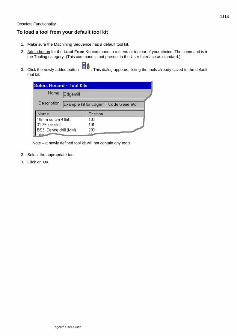
Obsolete Functionality
To load a tool from your default tool kit
Make sure the Machining Sequence has a default tool kit.1.
Add a button for the Load From Kit command to a menu or toolbar of your choice. The command is inthe Tooling category. (This command is not present in the User Interface as standard.)
2.
Click the newly-added button . This dialog appears, listing the tools already saved to the defaulttool kit:
3.
Note – a newly defined tool kit will not contain any tools.
Select the appropriate tool.2.
Click on OK.3.
1114
Edgcam User Guide

Obsolete Functionality
To save a tool in the Tool Library
You must have selected Mill Tool or Turn Tool (Tooling menu) or have clicked on a tool button. This displaysa dialog box for that type of tool.
Once you have specified the parameters of a particular tool, you may want to save it so that you can use thesame tool later.
When you are satisfied with the values of each parameter, select the Library tab. The Library tab dialogbox is displayed.
1.
Specify a reference Tool Name for the tool.2.
Check the Save Tool box.3.
Click on OK.4.
1115
Edgcam User Guide

Obsolete Functionality
Defining New Material Technology Tables
You may find that you need to create a completely new material technology table for your typical machiningtasks. In this case you must define a new table record in the Material Technology database in the Tool Library.
You can enter data into these tables based either on data from tool manufacturers’ handbooks or from yourown experience.
Remember which units you are working in – millimetres or inches. You cannot mix values within a singlerecord, but you can have two records however, one for inches and one for millimetres. These records can havethe same name (as long as they are using different units).
Rough , Medium or Fine values can be selected for a cycle.
The values for Surface Speed are in either metres per minute or feet per minute. The values for Feed 1 andFeed 2 are in “chip per tooth” (millimetres or inches per tooth). The values for Depth are in millimetres orinches.
To create a new record in the Material Technology database
Before proceeding, you should be familiar with the Tool Library.
Start the Tool Library program.
The Tool Library dialog box appears.
1.
Select Material from the Technology menu.
The Material search dialog box appears.
2.
Enter search parameters for the new table.3.
Click on OK.
The Tool Library searches for and displays a list of any matching records.
4.
Select the Insert operation control.
The Insert Record dialog box appears.
5.
Enter the parameters of the new record.
Click on OK to save the record.
6.
1116
Edgcam User Guide

Obsolete Functionality
Selecting values from technology tables in the Tool Library
Material technology tables are held in the Material Technology database in the Tool Library. You can alsoaccess them as follows:
Make sure Tool Library is activated.1.
In Design mode, click the Options menu and click Model.2.
Specify a Rigidity factor. If the material is weak or the clamping system exerts low holding forces, thenyou need to adjust this downwards. For example, a factor of 50% halves the theoretical speeds andfeeds. This applies to all tools used for the part.
3.
Search the database.
All records matching your search are displayed.
4.
Select the material data table you want to use.
Also see Defining New Material Technology Tables.
5.
To select values from tool technology tables
Use the Technology (Tooling menu) command in Manufacture mode if you want to select any tool ormaterial technology data for the current tool. Also see Viewing the Current Technology Values
1.
Use the Cut Type parameter to determine which set of material technology values you want to use fromthe current Material Technology table. Select from None, Rough, Medium or Fine. The default Cut Typeis Medium.
Select None to manually specify feed and speed parameters when the parameter input box for eachcycle that you select for the current tool.
2.
You can also specify a percentage Factor by which to multiply the values in the material technologytables. This is used to adjust the theoretical speeds and feeds for this tool only. For example, a longseries endmill needs to be driven slower than a short series endmill.
3.
Click OK.4.
1117
Edgcam User Guide

Obsolete Functionality
Rendering the Part
Classic Edgecam View only
The Render command lets you generate a more realistic image of the part. The command creates a bitmapimage which you can view on screen or save to a file, to view later in other software packages.
As standard, this command is not is not present in the user interface, so you will need to add the a button forthe command to a toolbar or menu of your choice. The command is in the View category.
A surface model can be displayed either as Wireframe or Rendered graphics. To switch between Wireframeand Rendered graphics, select the required option from the Display field on the View Properties dialog.Alternatively, use the 'Toggle Wireframe' icon from the Display toolbar.
Surfaces are rendered using the polygon mesh described with the surface Display parameters U Points and VPoints. Before rendering an image involving surfaces, make sure that these are set correctly.
The base entity colour is used as the base colour for the image.
To generate and display a rendered image of the current part
1118
Edgcam User Guide

Accessing Superseded Cycles
Superseded cycles are not available in the standard configurations; they do not appear in any menus ortoolbars.
To use a superseded cycle you need to add its command (button) to a menu or toolbar.
When adding the command, it will be found in the Superseded Commands category.
1119
Edgcam User Guide

Obsolete Functionality
Surface Areaclear and Lace Cycles
There are two superseded cycles for clearing material from selected surfaces:
Surface Areaclear
Surface Lace
In both these cycles the system forms a toolpath that is offset from the selected surface. The system alsokeeps the tool orientation fixed.
Use the Five Axis Areaclear (Mill Cycles menu) command to keep the tool normal to a surface whilemachining the surface.
To mill one or more surfaces
Click your newly-added Surface Areaclear or Lace button.1.
Complete the dialog that appears and click OK.2.
Select one or more surfaces to machine and then perform a Finish.3.
Digitise a new start point for the cycle if necessary and then perform a Finish.4.
The system now produces the toolpath.
1120
Edgcam User Guide

Accessing Superseded Operations
The superseded operations are not available in the standard configurations (default.config); they do not appearin any menus or toolbars.
To use a superseded operation, copy 'pre V9 operations.config' from:
installation_folder\Cam\Examples\Custom Configs\Mill Profile
to:
installation_folder\Cam\Support\Generic Profile
Then select the pre-V9 configuration to be restored. (Note that this does not apply to the Surfaces operationand Pencil Milling operation. For these you will need to add a command, as described below).
The superseded operations now appear in the Operations menu. (Note that once an operation becomessuperseded, in any subsequent installations the operation no longer has an icon.)
Alternatively you can add the operation's command from the Superseded Commands category to a menu ortoolbar of your choice.
1121
Edgcam User Guide

Obsolete Functionality
Superseded Hole Operation
This superseded Hole Operation command has been replaced by the Mill Cycles menu Holefor Milling and Mill Cycles menu Hole for Turning commands.
(These new operation dialogs have no Help button - the help is built into the dialogs themselves,as illustrations and 'tip' text.)
This command is not present in the User Interface as standard, so you will need to add thecommand button to a toolbar or menu yourself. The command is in the Superseded Commandscategory.
For reference purposes, here is the help on the Superseded Feature Finder dialog (you can also access thishelp by clicking the Help button in the dialog):
1122
Edgcam User Guide

Obsolete Functionality
Chamfer Operation
The Chamfer Operation command generates a single profile pass by selecting the top profile of a chamferededge.
This operation is superseded. The new version (of the same name) is available in the Operations menu. To usethe old version you need to follow the procedure in Accessing Superseded Operations. The old version has noicon.
Note that this operation will not work correctly with features found in Edgecam Version 9.0 or later, unless'Options (menu) Preferences Solids (tab) Superseded Feature Find' is checked.
See Also
Sequence of Instructions in the Chamfer Operation
Using the Chamfer Operation
Chamfer Operation Notes
1123
Edgcam User Guide

Obsolete Functionality
Sequence of Instructions in the Chamfer Operation
Chamfer[Standard Sequence]
Profiling Cycle See the Standard Sequence for Milling Operations for details of the standard sequence.
1124
Edgcam User Guide

Obsolete Functionality
Using the Chamfer Operation
Add the Chamfer Operation command (in the Superseded Commands category) to a menu or toolbar.1.
Select the newly added command.2.
Digitise the profile(s). Perform a Finish to stop selecting entities making up the profile(s).3.
Select a new start point for the active profile (if necessary) or press the Enter key.4.
Complete the dialog box for the operation. Click on OK.5.
Edgecam now generates the toolpaths for the chamfer operation, including any moves to position the tool.
1125
Edgcam User Guide
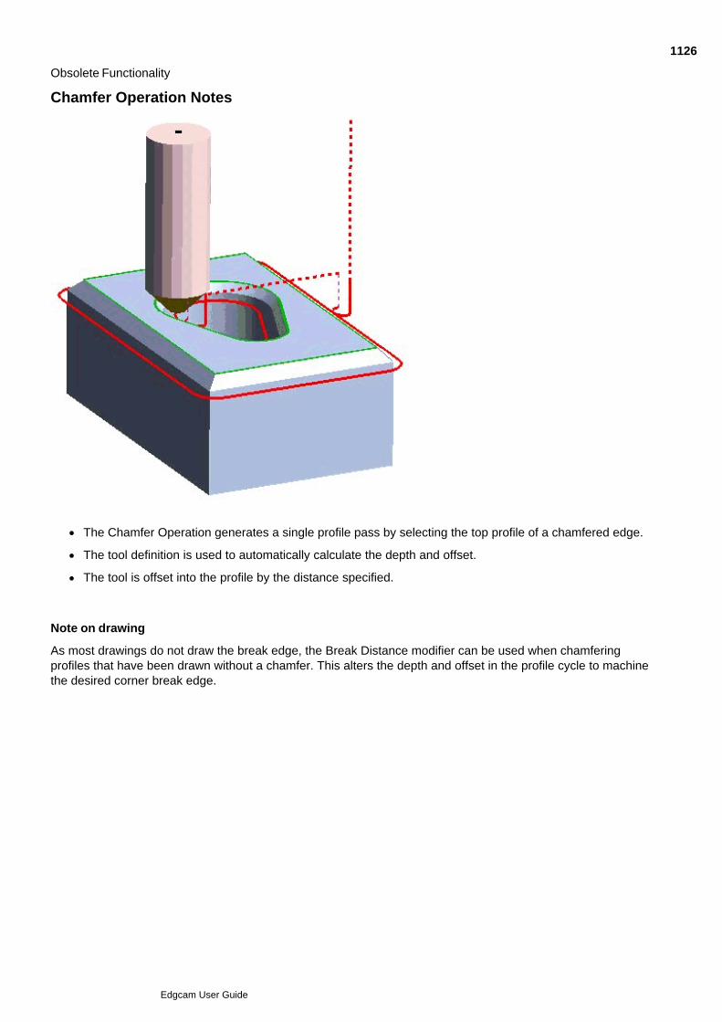
Obsolete Functionality
Chamfer Operation Notes
The Chamfer Operation generates a single profile pass by selecting the top profile of a chamfered edge.
The tool definition is used to automatically calculate the depth and offset.
The tool is offset into the profile by the distance specified.
Note on drawing
As most drawings do not draw the break edge, the Break Distance modifier can be used when chamferingprofiles that have been drawn without a chamfer. This alters the depth and offset in the profile cycle to machinethe desired corner break edge.
1126
Edgcam User Guide

Obsolete Functionality
Flat Land Finishing Operation
The Flat Land Finishing command allows you to combine a series of commands in one instruction. Theoperation produces a toolpath that machines flat areas using concentric or lace strategies.
This operation is superseded. The new version (of the same name) is available in the Operations menu.
To use the old version you need to follow the procedure in Accessing Superseded Operations..
Note that this operation will not work correctly with features found in Edgecam Version 9.0 or later, unless'Options (menu) Preferences Solids (tab) Superseded Feature Find' is checked.
See Also
Sequence of Instructions in the Flat Land Finishing Operation
Using the Flat Land Finishing Operation
Flat Land Finishing Cycle
1127
Edgcam User Guide

Obsolete Functionality
Sequence of Instructions in the Flat Land Finishing Operation
Flat Land Finishing
[Standard Sequence]
Flat Land Finishing Cycle
See the Standard Sequence for Milling Operations for details of the standard sequence.
1128
Edgcam User Guide

Obsolete Functionality
Using the Flat Land Finishing Operation
Add the Flat Land Finishing Operation command (in the Superseded Commands category) to a menuor toolbar.
1.
Select the newly added command.2.
Digitise the surfaces to be machined, then perform a Finish.3.
Digitise the boundary entities (if any are required), then perform a Finish.4.
Complete the dialog box for the operation, then click OK.*5.
Edgecam now generates the toolpaths for the finishing operation, including any moves to position the tool.
* The operation allows blank level and depth fields. When no values are specified level and depth are takenfrom the model.
1129
Edgcam User Guide

Obsolete Functionality
2D Profile Operation
The 2D Profile Operation command allows you to use several commands together in one operation.
This operation is superseded by the Profiling operation; the command for this is in the Operations menu.
To use the old version you need to follow the procedure in Accessing Superseded Operations.
Please note that a new Profile operation was introduced in Edgecam version 7.75. The previous Profileoperation is still available to pre-version 7.75 parts and will be used if the operation is edited or regenerated. Touse the new method on an existing part, delete the old operation and re-apply the new operation. Note that this operation will not work correctly with features found in Edgecam Version 9.0 or later, unless'Options (menu) Preferences Solids (tab) Superseded Feature Find' is checked.
See Also
Sequence of Instructions in the 2D Profile Operation
Using the 2D Profile Operation
2D Profile Cycle
1130
Edgcam User Guide

Obsolete Functionality
Sequence of Instructions in the 2D Profile Operation
Profiling
[Standard Sequence]
Cutter Compensation – Left/Right
2D Profile Cycle
Cutter Compensation – None See the Standard Sequence for Milling Operations for details of the standard sequence.
1131
Edgcam User Guide
Obsolete Functionality
Using the 2D Profile Operation
Add the 2D Profile Operation command (in the Superseded Commands category) to a menu or toolbar.1.
Select the newly added command..2.
Digitise the profile(s). Perform a Finish to stop selecting entities making up the profile(s).3.
The Profile operation will only ask for the profile selection, not the material side. Start and end positionscan only be controlled using the Profile Extensions on the General tab (open profiles only). In the case ofclosed profiles, the start point is set to the nearest start, end or midpoint on the profile when it isselected.
4.
Perform a Finish.5.
Complete the dialog box for the operation. Click on OK.6.
Edgecam now generates the toolpaths for the profile operation, including any moves to position the tool.
Profile Material on the Left
This option is used to take advantage of the feature material side and to maintain associativity between thefeature and the Profile operation.
When manually identifying features in Edgecam Solid Machinist, the direction of the profile is automaticallyselected such that the material is on the left. Checking the Profile Material on the Left option on theGeneral tab of the Preferences (Operations menu) dialog will allow the machining operation to cut thecorrect side of the feature without any further intervention from the user.
This method can be used on wireframe geometry by chaining the profile in the correct direction so as tomaintain the material on the left.
1132
Edgcam User Guide

Obsolete Functionality
3D Roughing Operation
The 3D Roughing Operation command allows you to combine a series of commands in one instruction.
This operation is superseded by the Roughing operation; the command for this is in the Operations menu.
To use the old version you need to follow the procedure in Accessing Superseded Operations.
Note that this operation will not work correctly with features found in Edgecam Version 9.0 or later, unless'Options (menu) Preferences Solids (tab) Superseded Feature Find' is checked.
See Also
Sequence of Instructions in the 3D Roughing Operation
Using the 3D Roughing Operation
Roughing Cycle
1133
Edgcam User Guide

Obsolete Functionality
Sequence of Instructions in the 3D Roughing Operation
Roughing/Rest Roughing
[Standard Sequence]
Roughing Cycle See the Standard Sequence for Milling Operations for details of the standard sequence.
1134
Edgcam User Guide

Obsolete Functionality
Using the 3D Roughing Operation
Add the 3D Roughing Operation command (in the Superseded Commands category) to a menu ortoolbar.
1.
Select the newly added command.2.
Digitise the surfaces to be machined, then perform a Finish.3.
Digitise the boundary entities (if any are required), then perform a Finish.4.
Complete the dialog box for the operation.*5.
If required, check the Rest Rough option to apply a rest roughing cycle. When checked, the cycle usesthe information from the last roughing cycle. If no appropriate cycle precedes the rest rough cycle anerror message will be displayed.
6.
Click OK.7.
Edgecam now generates the toolpaths for the roughing operation, including any moves to position the tool.
* The operation allows blank level and depth fields. When no values are specified level and depth are taken
from the model.
1135
Edgcam User Guide

Obsolete Functionality
Pocket Operation
The Pocket command allows you to combine a series of commands in one instruction. This operation is superseded. To use it you need to add its command to a toolbar or menu from theSuperseded Commands category. The operation has no icon. Note that this operation will not work correctly with features found in Edgecam Version 9.0 or later.
See Also
Sequence of Instructions in the Pocket Operation
Using the Pocket Operation
2D Profile Cycle
1136
Edgcam User Guide

Obsolete Functionality
Sequence of Instructions in the Pocket Operation
Roughing
[Standard Sequence]
Areaclear/Lace Cycle (superseded cycles)
Finishing
[Standard Sequence]
Cutter Compensation – Left/Right
2D Profile Cycle (superseded cycles)
Cutter Compensation – None See the Standard Sequence for Milling Operations for details of the standard sequence.
1137
Edgcam User Guide

Obsolete Functionality
Using the Pocket Operation
Add the Pocket Operation command (in the Superseded Commands category) to a menu or toolbar.1.
Select the newly added command.2.
Digitise the pocket profiles. Perform a Finish to stop selecting entities making up the profile(s).3.
Digitise a new start point for the profile chain (if necessary). Perform a Finish.4.
Complete the dialog box for the operation. Click on OK.5.
Edgecam now generates the toolpaths for the pocket operation, including any moves to position the tool.
1138
Edgcam User Guide

Obsolete Functionality
Facemilling Operation (Superseded)
Facemilling Operation allows you to combine a series of commands in one instruction.
This operation is superseded by the Face Mill operation; the command for this is in the Operations menu.
To use the superseded version you need to follow the procedure in Accessing Superseded Operations.
Note that this operation will not work correctly with features found in Edgecam Version 9.0 or later, unless'Options (menu) Preferences Solids (tab) Superseded Feature Find' is checked.
The Facemilling operation uses the (superseded) 'Pre V7 Facemill' cycle.
See Also
Sequence of Instructions in the Facemilling Operation
Using the Facemilling Operation
1139
Edgcam User Guide

Obsolete Functionality
Using the Facemilling Operation
Click on the Facemilling Operation button.1.
Digitise a start point for the facemilling cycle. You can use a ‘free’, ‘entity’ or ‘grid’ digitise to define thestart point.
2.
Digitise a direction for the cycle.3.
Digitise an end point for the cycle.4.
Complete the dialog box for the operation. Click on OK.5.
Edgecam now generates the toolpaths for the facemilling cycle, including any moves to position the tool.
For a detailed description of the operation parameters, please refer to the context sensitive help for the dialog.
1140
Edgcam User Guide

Obsolete Functionality
Sequence of Instructions in the Facemilling Operation
[Standard Sequence for Milling Operations]
Pre V7 Facemill cycle
1141
Edgcam User Guide

Obsolete Functionality
Pencil Mill Operation
Pencil Milling (Operations menu) is a finishing operation making a single pass along internal edges.Please note that the Pencil Mill operation only supports ballnose cutters.
A new pencil mill cycle was introduced in Edgecam version 7.50. Please note that the Pencil Mill operationuses the "old" (i.e. pre-version 7.50) cycle.
See Also
Sequence of Instructions in the Pencil Mill Operation
Using the Pencil Mill Operation
1142
Edgcam User Guide

Obsolete Functionality
Using the Pencil Mill Operation
A new pencil mill cycle was introduced in Edgecam version 7.50. Please note that the Pencil Mill operationuses the "old" (i.e. pre-version 7.50) cycle.
Click on the Pencil Mill Operation button.1.
Digitise the surfaces to be machined, then perform a Finish.2.
Digitise the containment boundary entities (if required), then perform a Finish.3.
Complete the dialog box for the operation, then click OK.4.
Edgecam now generates the toolpaths for the pencil mill operation, including any moves to position the tool.
1143
Edgcam User Guide

Obsolete Functionality
Sequence of Instructions in the Pencil Mill Operation
A new pencil mill cycle was introduced in Edgecam version 7.50. Please note that the Pencil Mill operationuses the "old" (i.e. pre-version 7.50) cycle.
Pencil Mill
[Standard Sequence]
Pencil Mill Cycle See the Standard Sequence for Milling Operations for details of the standard sequence.
1144
Edgcam User Guide

Obsolete Functionality
Surfaces Operation
Use Surfaces (Operations menu) to combine a series of commands in one instruction.
See Also
Sequence of Instructions in the Surface Operation
Using the Surface Operation
Parallel Lace Cycle
Profiling Cycle
1145
Edgcam User Guide

Obsolete Functionality
Using the Surfaces Operation
Click on the Surface Operation button.1.
Digitise the surfaces to be machined, then perform a Finish.2.
Digitise the boundary entities (if any are required), then perform a Finish.3.
Digitise a point or a line to act as the start position for the operation, then perform a Finish.4.
Complete the dialog box for the operation, then click OK.*5.
Edgecam now generates the toolpaths for the surface operation, including any moves to position the tool.
* The operation allows blank level and depth fields. When no values are specified level and depth are taken
from the model. Note that the Surface operation will still give an error for level and depth if Z LevelRoughing is used (Lace, Areaclear or Boss) since these cycles require level and depth input.
1146
Edgcam User Guide

Obsolete Functionality
Sequence of Instructions in the Surfaces Operation
Roughing
[Standard Sequence]
Parallel Lace or Z Level Roughing Lace or Z Level Roughing Areaclear or Z Level Roughing External Boss
(Note that Z Level Roughing Lace, Z Level Roughing Areaclear and Z Level Roughing External Boss are allsuperseded cycles.)
Finishing
[Standard Sequence]
Parallel Lace/Profiling/ Constant Cusp Finishing (licence permitting)
1147
Edgcam User Guide

Obsolete Functionality
Verifying the Model
You may want to check that the machining is satisfactory before running the CNC code on an actual machinetool.
We recommend you do this using Edgecam Simulator.
However there is a superseded tool you can use; Edgecam Verify. This provides a fully rendered simulation ofthe machining sequence, clearly highlighting any gouging or rapid tool motions through the work or fixtures.
As it is superseded, the 'Verify Machining' command does not appear on a toolbars or menu in the defaultconfigurations. You need to add a button for the command yourself. The command is in the View category.
Click on the links below to view an Edgecam part and three stages in the generation of a solid model inEdgecam Verify.
Example Edgecam part
Solid model in Edgecam Verify
You should be aware that the machining time displayed in Verify is calculated on time spent doing feed moves,and so will not agree with the machining time calculated within Edgecam.
1148
Edgcam User Guide
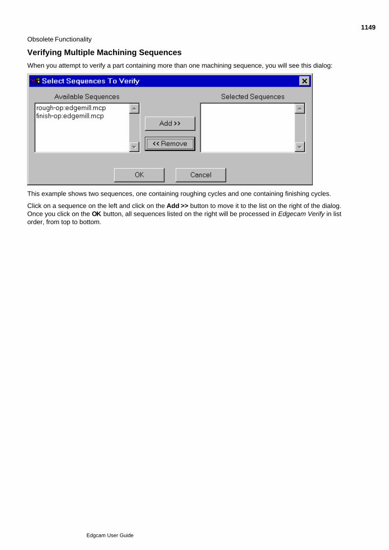
Obsolete Functionality
Verifying Multiple Machining Sequences
When you attempt to verify a part containing more than one machining sequence, you will see this dialog:
This example shows two sequences, one containing roughing cycles and one containing finishing cycles.
Click on a sequence on the left and click on the Add >> button to move it to the list on the right of the dialog.Once you click on the OK button, all sequences listed on the right will be processed in Edgecam Verify in listorder, from top to bottom.
1149
Edgcam User Guide
Obsolete Functionality
Non-Hole Superseded Features
For Superseded Hole features see Superseded Hole Features.
Non-hole superseded features are features which were:
created using a release of Edgecam prior to Version 9.0, or
found using the 'Superseded' feature identifying commands: Superseded Pocket, Superseded ThroughPocket, Superseded External Boss, Superseded Profile, or
found using the Feature Finder, with the Superseded (Pockets or Bosses) option checked (note you onlysee this option if Options menu Preferences Solids tab Superseded Feature Find ischecked).
We recommend you work with 'new' features, but you can still work with the superseded features to maintainbackwards compatibility.
Superseded features are similar to 'new' features; they appear in the Features Window for example and youedit them in the same way. There are differences however; for example:
The superseded features do not work correctly with operations introduced in Edgecam 9.0 or later.
Superseded features can only have 2D geometry, so a superseded pocket can only have straight sides,for example. (New features can have more complex geometry.)
Edits to superseded features are overwritten on re-loading the solid. (The edits you make to new featuresare not overridden on re-loading the solid.)
Superseded features cannot be nested; they all effectively have a 'Nesting Status' property of 'Single'.
Superseded features (only) can be 'exploded' into their constituent geometry, using Edit menu Explode. This would be useful where a feature was not suitable for machining as a whole, but someitems of its geometry could be used on their own. Note that:
The original feature is deleted and you loose associativity.
It might be better to create the geometry directly from the solid. For example you could use Solidsmenu Edge Loop Feature to create a containment boundary for a cycle's toolpath (maintainsassociativity), or you could use Solids menu Geometry to create 2D or 3D entities.
1150
Edgcam User Guide

Obsolete Functionality
Superseded Hole Features
Hole features of the superseded type can be identified by their Type property of 'FT_HOLE'. , rather than'FT_HOLE2' for non-superseded holes.
We recommend you use the non-superseded 'Hole' type (Type property of 'FT_HOLE') as, for example, thisoffers more complex geometry options and the holes can be radial.
To find superseded holes you need to check Options menu Preferences Solids tab SupersededFeature Find. Then in the Feature Finder dialog you will see a Holes checkbox in the Superseded section -check this.
You can also find superseded holes using Solids menu Superseded Features Hole.
Note that superseded holes cannot be machined by the Hole cycle (only the Superseded Hole cycle).
1151
Edgcam User Guide

Obsolete Functionality
Editing Features
You can modify feature information by using the Entity Data (Edit menu) command or by right-clicking on thefeature in the Features Window and selecting the Edit command from the shortcut menu.
You can also use the Properties Window (for certain properties only; Depth for example is not editable).
Edgecam allows you to override attribute values such as depth, level, colour, name etc. However, if you reloadthe model the modifiers level, depth and diameter will be reset to the values of the reloaded solid. Any otherproperties are retained.
When altering the level of a feature, the Preserve Depth option allows you to maintain the absolute depth.Otherwise the feature depth (which is relative to the level) will move with the level by default.
Setting comment attributes for use in Strategy Manager
In Strategy Manager, you may need to determine if a hole feature needs to be finish reamed or bored or if thefeature is a special feature requiring its own unique machining process. The Comment field on the edit dialogfor hole and pocket/boss features allows you to set a comment attribute (of up to 255 characters). This textstring allows you to label the feature and can then be checked in Strategy Manager to ensure that theappropriate machining process is applied.
1152
Edgcam User Guide

Obsolete Functionality
Superseded Turn Features
Superseded Turn features are features which were:
Found in an Edgecam version prior to Version 12.5.
Or found using the superseded Feature Finder command, in Version 12.5 or later.
Or found using the Solids menu Turn Feature command.
Although compatible in terms of the cycles they support, we recommend you use the latest Turn features, asfound using the Feature Finder command. These are more intuitive to use and support more properties.
An example of of superseded Turn feature is 'External Turn' (replaced by the 'Front Turn' and 'Back Turn'featues) - see an illustration of the full set...
Edit Superseded Turn Features using the Turn Profile Feature dialog (or the Properties Window).
1153
Edgcam User Guide
Obsolete Functionality
Entities Supported in SAT (Solids Interface Licence retired at V9.0)
This table shows how ACIS topological entities are loaded into Edgecam:
ACIS Topological Entity Loaded in Edgecam as
BODY Multiple Faces
WIRE Multiple Edges
FACE Single Trimmed Surface
EDGE Single Curve
ACIS geometrical types are converted to Edgecam entities when they are referred to by the topological entitiesas listed above. The following table lists the ACIS geometrical types and their corresponding Edgecamequivalent entities:
ACIS Geometry Equivalent Edgecam Entity
Surface
SPHERE Surface of revolution
CONE Surface of revolution
TORUS Surface of revolution
Other types B-Spline surface
Curve
STRAIGHT Line
ELLIPSE
radius ratio = 1.0 Arc
radius ratio ¹ 1.0 Ellipse
INTCURVE NURB curve
1154
Edgcam User Guide
Obsolete Functionality
Licencing Scheme
SAT and ACIS files are loaded as entities (lines, arcs, surfaces) or solid models, according to your Edgecamlicences:
Licence
SolidsInterface(retired atV9.0)
Solid Machinist for ACIS
to loadas entities
UseFile Open
use
install folder\cam\support\loadsat.pci
where install folder is 'C:\Program Files\Edgecam'for example
to loadas a solid model
not possible Use File Open
1155
Edgcam User Guide

Obsolete Functionality
Layers from ACIS (Solids Interface Licence retired at V9.0)
ACIS entities loaded into Edgecam will be placed on layers as follows:
Entities loaded Edgecam layer
Edges “Curves”
Faces “Surfaces”
Surface Groups “Surface Groups”
1156
Edgcam User Guide

Obsolete Functionality
Creating Surface Analysis Models
Use the Analysis Model command to create a surface analysis model. This functionality was originally usedwith the Combination Finishing cycle but is still useful as an aid for visualising models.
The command is not in any menus or toolbars in the default configurations; you will need to add it yourself. Thecommand is in the Mill Cycles command category.
The Analysis Model is dependent upon the current CPL of the machining sequence, and so is created as aManufacturing Instruction. The cycle uses the Model to generate the containment boundaries used by theParallel Lace and Profiling cycles.
The Analysis Model data is referenced in the database as a new entity type. This maintains associativity withthe part file and all surfaces selected to generate the model. The entity also holds relevant data such as densityand colour. Each Edgecam part file (ppf) can create a number of Analysis Models, and these are typicallystored in the folder \edge\cam\Analysis\. You can change this folder in the Analysis Model Folder parameter inthe Surface tab of the Preferences (Options menu) command.
The Selection Strategy allows you to select all visible surfaces, digitise them individually or to specify adigitised window. Digitise Window has the benefit of containing the analysis model to a square area rather thanto the extents of the selected surfaces.
The Resolution of the model can be set to Low, Medium, High or specify grid size. A high density gives agreater accuracy of model but takes longer to compute. ‘High’ does produce smoother and more accuratecontainment boundaries. If desired you may select the Specify Grid Size option, where the distance betweenthe grid points can be entered directly. However, a warning will be issued if the overall density of the model istoo large.
The analysis model forms a rectangular grid of points lying along the X axis of the CPL. The Grid angle can beused to tip the grid through the specified angle to better match the selected surfaces.
Once complete the command displays a Patch grid of the Analysis Model over the surfaces. The parameterscontrolling this patch grid are on the Display tab.
At any time during the machining sequence, you can create additional Analysis Models on different regions ofthe part. Some of the selected surfaces may already be members of two or more Analysis Models.
See Also
Analysis Model Type
Analysis Viewer
1157
Edgcam User Guide
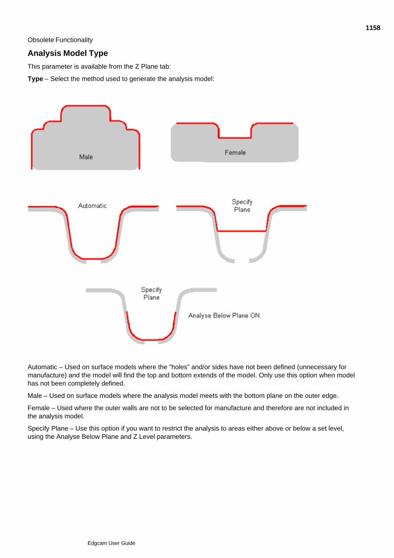
Obsolete Functionality
Analysis Model Type
This parameter is available from the Z Plane tab:
Type – Select the method used to generate the analysis model:
Automatic – Used on surface models where the “holes” and/or sides have not been defined (unnecessary formanufacture) and the model will find the top and bottom extends of the model. Only use this option when modelhas not been completely defined.
Male – Used on surface models where the analysis model meets with the bottom plane on the outer edge.
Female – Used where the outer walls are not to be selected for manufacture and therefore are not included inthe analysis model.
Specify Plane – Use this option if you want to restrict the analysis to areas either above or below a set level,using the Analyse Below Plane and Z Level parameters.
1158
Edgcam User Guide
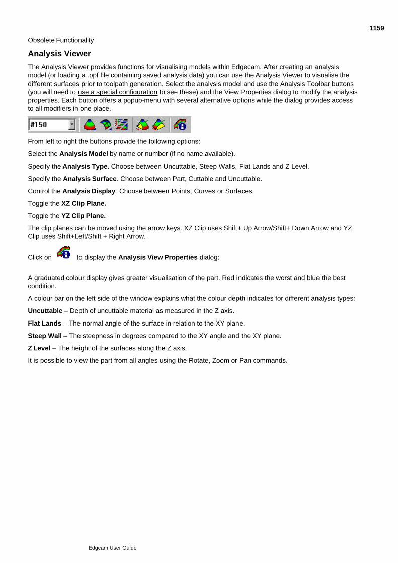
Obsolete Functionality
Analysis Viewer
The Analysis Viewer provides functions for visualising models within Edgecam. After creating an analysismodel (or loading a .ppf file containing saved analysis data) you can use the Analysis Viewer to visualise thedifferent surfaces prior to toolpath generation. Select the analysis model and use the Analysis Toolbar buttons(you will need to use a special configuration to see these) and the View Properties dialog to modify the analysisproperties. Each button offers a popup-menu with several alternative options while the dialog provides accessto all modifiers in one place.
From left to right the buttons provide the following options:
Select the Analysis Model by name or number (if no name available).
Specify the Analysis Type. Choose between Uncuttable, Steep Walls, Flat Lands and Z Level.
Specify the Analysis Surface. Choose between Part, Cuttable and Uncuttable.
Control the Analysis Display. Choose between Points, Curves or Surfaces.
Toggle the XZ Clip Plane.
Toggle the YZ Clip Plane.
The clip planes can be moved using the arrow keys. XZ Clip uses Shift+ Up Arrow/Shift+ Down Arrow and YZClip uses Shift+Left/Shift + Right Arrow.
Click on to display the Analysis View Properties dialog:
A graduated colour display gives greater visualisation of the part. Red indicates the worst and blue the bestcondition.
A colour bar on the left side of the window explains what the colour depth indicates for different analysis types:
Uncuttable – Depth of uncuttable material as measured in the Z axis.
Flat Lands – The normal angle of the surface in relation to the XY plane.
Steep Wall – The steepness in degrees compared to the XY angle and the XY plane.
Z Level – The height of the surfaces along the Z axis.
It is possible to view the part from all angles using the Rotate, Zoom or Pan commands.
1159
Edgcam User Guide

Obsolete Functionality - Not in Standard User Interface
Superseded Hole Cycle
Note that this cycle is superseded and is no longer featured in the User Interface.
The User Interface features a new version of the cycle that we recommend you to use, as it has additionalfunctionality such as radial hole support. This 'old' cycle, is maintained for compatibility purposes, along withthese User Guide topics.
The Hole Cycle command provides all the functionality for the different hole creation methods.
Throughout this chapter, the term “drilling” in the general sense includes all strategies for creating holes.
The procedure for performing hole cycles depends on your selection of Depth parameters.
You can select points, lines or arcs as input for the Edgecam drilling cycles. When selecting arcs, the centre ofthe arc is drilled. Please note that arcs must lie in the current CPL. Also see Filtering Drill Entities.
You will be able to optimise the resulting toolpath using different patterns. See Optimising the Toolpath.
You can also use the Hole (Operations menu) command to combine several related drilling commands. SeeOperational Programming in Milling for details of using operations.
See Also
Choosing the Drilling Strategy
Filtering Drill Entities
Specifying Depth Parameters for Drilling
Controlling the Tool's Entry Feedrate
Controlling the Tool's Approach to Depth for Drilling
Using Drilling Subroutines on a Milling Centre
Output Drilling in Longhand Format
Using Drilling Canned Cycles on a Turning Centre
Optimising the Toolpath
1160
Edgcam User Guide

Obsolete Functionality
Choosing the Drilling Strategy
Use the Strategy parameter on the General tab to select the way in which you want to create the hole. Choosefrom:
Drill - The tool retracts between pecks at the rapid rate.
Chipbreak - This cycle works in the same way as Drill, but the tool retracts by 1mm or .05” after each peck.
Ream - The tool feeds to Depth, then feeds up to the Clearance plane.
Bore - The tool retracts between pecks at the rapid rate. When the tool reaches the specified Depth for thecycle, the tool spindle stops. The tool then indexes, locks and shifts before retracting to avoid scoring the borehole.
Tap - The tool feeds to the specified Depth and dwells as required. The spindle is then reversed and the toolfeeds out.
1161
Edgcam User Guide

Obsolete Functionality
Filtering Drill Entities
The Filtering tab of the Hole cycle dialog allows you to define how entities to be drilled are filtered. (Notavailable for axial drilling)
Arc Centres
As Tool Diameter – Check to only drill arcs of the same diameter as the tool (plus or minus tolerance specifiedbelow).
Incomplete Arcs – When checked, incomplete arcs (i.e. arcs that are not a full circle) will be drilled.
Minimum Diameter – Specifies the minimum arc size to be drilled.
Maximum Diameter – Specifies the maximum arc size to be drilled.
Tolerance – Specifies the tolerance used when matching tool to arc.
Lines
Vertical – Check to set level and depth from vertical line, any non-vertical lines will be ignored.
5.0 Compatibility
Drill Duplicates - (Compatibility switch) Edgecam automatically detects pre-version 5.0 drilling cycles andchecks this box when coincidental drill points are found.
1162
Edgcam User Guide

Obsolete Functionality
Specifying Depth Parameters for Drilling
Each drilling cycle has a set of Depth parameters that control the vertical motion of the tool before, during andafter each drilling operation.
The Depth tab of the Hole cycle dialog offers the following parameters:
Clearance – Defines the height the tool lifts to between holes and at the end of the cycle.
Retract – Defines the height the tool retracts to between pecks.
Level – An absolute value that defines the surface of the workpiece.
Depth – Defines the depth of the hole to be drilled.
Intelli Drill
This functionality is not available for axial fixed tool drilling.
Multi Level – Check to drill a series of holes at differing levels. The level for the cycle will be taken from thedigitised geometry (arc, line or point). The cycle applies the Depth and Retract values relative to the Level ofthe digitised entity. Any specified Level parameter value is ignored.
Multi Depth – (Code Generator dependent) Check to drill a series of holes at different depths, the depth for thecycle is taken from an arc, line or point at the base of the hole. Where an entity to define the depth is notselected the Depth parameter from the cycle dialog will be used. If arcs with a (connecting) vertical line areselected the depth will be taken from the vertical line. Please note that it is still necessary to specify a Depthvalue (which will not be applied), otherwise an error will be displayed.
It is necessary to check Multi level in order for the Multi Depth option to work.
See Also
Tool Depths with Hole Cycles
Drilling a Series of Points at Differing Levels
Drilling a Series of Points at Differing Depths
Retract Values in Drilling
1163
Edgcam User Guide
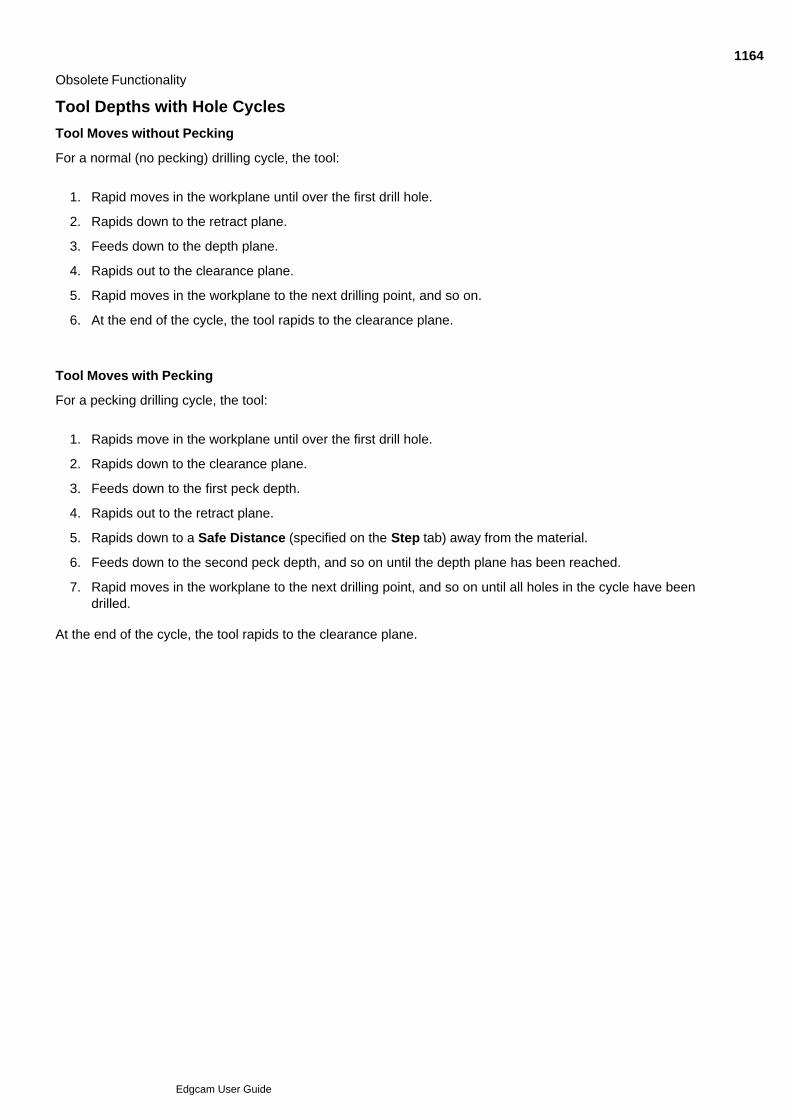
Obsolete Functionality
Tool Depths with Hole Cycles
Tool Moves without Pecking
For a normal (no pecking) drilling cycle, the tool:
Rapid moves in the workplane until over the first drill hole.1.
Rapids down to the retract plane.2.
Feeds down to the depth plane.3.
Rapids out to the clearance plane.4.
Rapid moves in the workplane to the next drilling point, and so on.5.
At the end of the cycle, the tool rapids to the clearance plane.6.
Tool Moves with Pecking
For a pecking drilling cycle, the tool:
Rapids move in the workplane until over the first drill hole.1.
Rapids down to the clearance plane.2.
Feeds down to the first peck depth.3.
Rapids out to the retract plane.4.
Rapids down to a Safe Distance (specified on the Step tab) away from the material.5.
Feeds down to the second peck depth, and so on until the depth plane has been reached.6.
Rapid moves in the workplane to the next drilling point, and so on until all holes in the cycle have beendrilled.
7.
At the end of the cycle, the tool rapids to the clearance plane.
1164
Edgcam User Guide

Obsolete Functionality
Drilling a Series of Points at Differing Levels
To use the hole cycle with multi level set
Select the Hole (Mill Cycles menu) command. A dialog appears showing the parameters for the cycle.1.
Enter the parameters for the cycle.2.
On the Depth tab, select the Intelli Drill option Multi Level.3.
Digitise the entities to be drilled. This also provides the Z level information for each hole. The cycleapplies the Depth and Retract values relative to the Level of the digitised entity.
4.
Perform a Finish.5.
The toolpath is now generated.
1165
Edgcam User Guide

Obsolete Functionality
Drilling a Series of Points at Differing Depths
Please note that this option is Code Generator dependent.
To use the hole cycle with multi depth set
Select the Hole (Cycle menu) command; A dialog appears showing the parameters for the cycle.1.
Enter the parameters for the cycle.2.
On the Depth tab, select the Intelli Drill option Multi Depth.3.
Digitise the entities to be drilled. If a point or an arc is selected the specified Depth will be applied. If arcswith a (connecting) vertical line are selected the depth will be taken from the vertical line. Please notethat it is still necessary to specify a Depth value (which will not be applied), otherwise an error will bedisplayed.
4.
Perform a Finish.5.
The toolpath is now generated.
1166
Edgcam User Guide

Obsolete Functionality
Retract Values in Drilling
When completing a “Hole Cycle” dialog you are asked for depth settings of ZLEVEL, RETRACT DISTANCE,DEPTH and ZCLEAR.
For single level cycles the RETRACT DISTANCE is passed to the Code Generator as a Retract Plane set atZLEVEL+RETRACT. If no retract distance is given the Retract Plane defaults to the Clearance Plane Height.
For Multi level drilling the ZLEVEL is ignored and a RETRACT distance is passed to the Code Generator. If aRETRACT distance is not stated it defaults to the ZCLEAR height. The Code Generator will then set up aRetract plane based on the height of the first point and that Retract Distance. For this reason it isrecommended that in Multi Level Drilling a RETRACT distance should always be entered in the dialog.
If any multilevel cycles are to be used it is suggested that for best results all hole cycles with the same toolshould be treated as multilevel. A combination of multilevel and single level cycles with the same tool may notgive the expected NC output.
1167
Edgcam User Guide
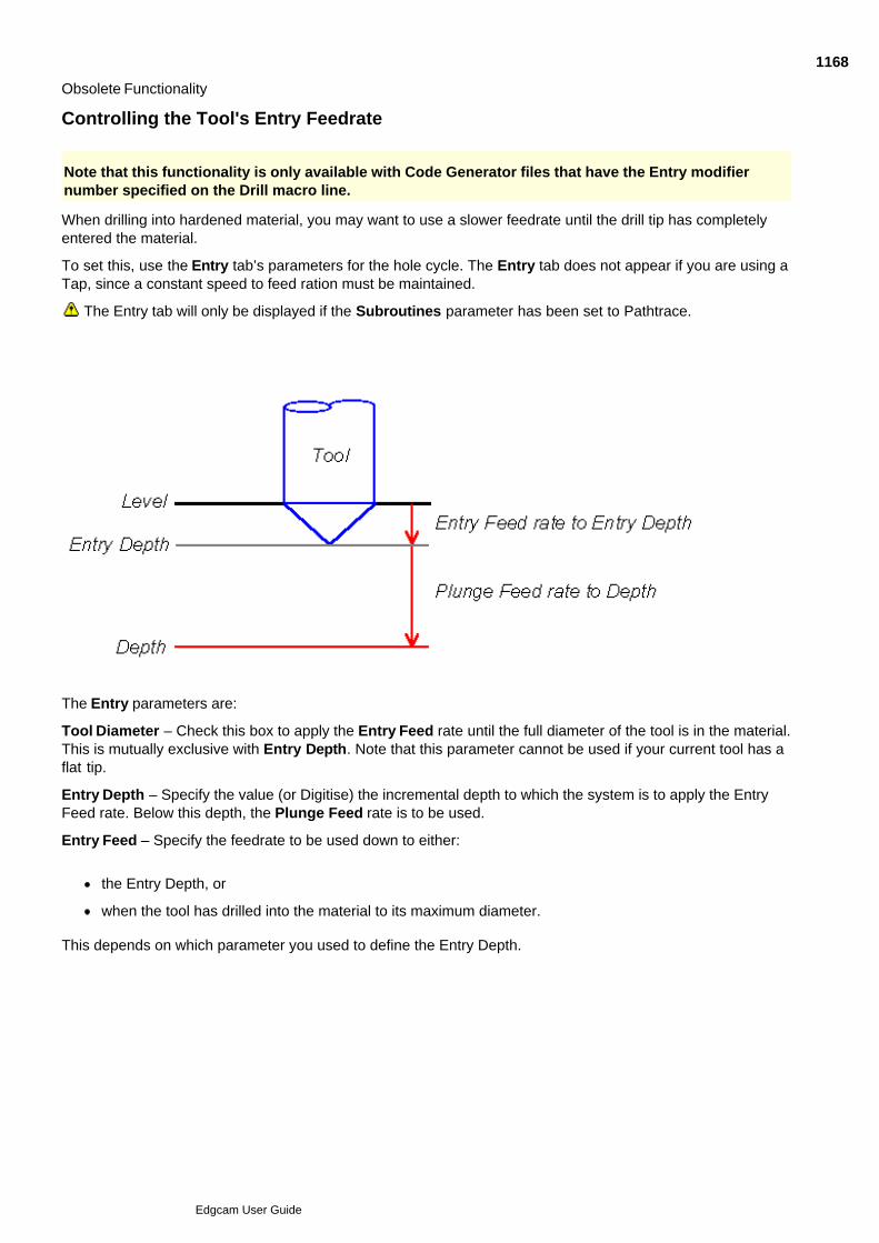
Obsolete Functionality
Controlling the Tool's Entry Feedrate
Note that this functionality is only available with Code Generator files that have the Entry modifiernumber specified on the Drill macro line.
When drilling into hardened material, you may want to use a slower feedrate until the drill tip has completelyentered the material.
To set this, use the Entry tab’s parameters for the hole cycle. The Entry tab does not appear if you are using aTap, since a constant speed to feed ration must be maintained.
The Entry tab will only be displayed if the Subroutines parameter has been set to Pathtrace.
The Entry parameters are:
Tool Diameter – Check this box to apply the Entry Feed rate until the full diameter of the tool is in the material.This is mutually exclusive with Entry Depth. Note that this parameter cannot be used if your current tool has aflat tip.
Entry Depth – Specify the value (or Digitise) the incremental depth to which the system is to apply the EntryFeed rate. Below this depth, the Plunge Feed rate is to be used.
Entry Feed – Specify the feedrate to be used down to either:
the Entry Depth, or
when the tool has drilled into the material to its maximum diameter.
This depends on which parameter you used to define the Entry Depth.
1168
Edgcam User Guide

Obsolete Functionality
Controlling the Tool's Approach to Depth for Drilling
A series of parameters under the Step tab define how the tool pecks down to the specified Depth for the holecycle:
Cut Increment – Specifies the amount of material penetrated by each peck by the tool. This value can bereduced each peck by the Degression value.
Degression – Specifies the distance that the Cut Increment is reduced by on each peck.
This also defines the smallest possible Cut Increment. If the Cut Increment is reduced to an equal or lowervalue compared to the Degression value, the Cut Increment is set to the Degression value.
Safe Distance – Specifies the height from the current depth of the hole that the tool moves to before eachpeck.
1169
Edgcam User Guide

Obsolete Functionality
Using Drilling Subroutines on a Milling Centre
The Subroutines parameter is present in milling cycles that could allow the machine tool controller to generatesubprograms.Select between:
Controller – Allows the controller to generate subprograms if more than one operation is performed on anidentical pattern (for example, a set of points).
Pathtrace – Stops the controller from generating subroutines.
1170
Edgcam User Guide

Obsolete Functionality
Output Drilling in Longhand Format.
Longhand cycle expansion is implemented in all standard milling code wizard templates.
In the Superseded Hole cycle, it is not available for controller subroutines, stand-off boring or tapping cycles.'
1171
Edgcam User Guide

Obsolete Functionality
Using Drilling Canned Cycles on a Turning Centre
The Canned Cycles parameter is present in turning cycles that could use existing cycles held by the machinetool controller.
Check the box to use the controller canned cycle for the drilling cycle. Leave blank to use the CNC codegenerated by Edgecam.
1172
Edgcam User Guide
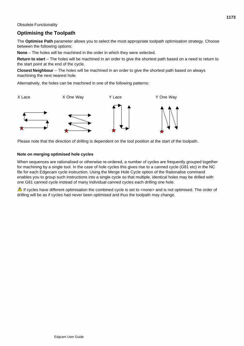
Obsolete Functionality
Optimising the Toolpath
The Optimise Path parameter allows you to select the most appropriate toolpath optimisation strategy. Choosebetween the following options:
None – The holes will be machined in the order in which they were selected.
Return to start – The holes will be machined in an order to give the shortest path based on a need to return tothe start point at the end of the cycle.
Closest Neighbour – The holes will be machined in an order to give the shortest path based on alwaysmachining the next nearest hole.
Alternatively, the holes can be machined in one of the following patterns:
X Lace X One Way Y Lace Y One Way
Please note that the direction of drilling is dependent on the tool position at the start of the toolpath.
Note on merging optimised hole cycles
When sequences are rationalised or otherwise re-ordered, a number of cycles are frequently grouped togetherfor machining by a single tool. In the case of hole cycles this gives rise to a canned cycle (G81 etc) in the NCfile for each Edgecam cycle instruction. Using the Merge Hole Cycle option of the Rationalise commandenables you to group such instructions into a single cycle so that multiple, identical holes may be drilled withone G81 canned cycle instead of many individual canned cycles each drilling one hole.
If cycles have different optimisation the combined cycle is set to <none> and is not optimised. The order ofdrilling will be as if cycles had never been optimised and thus the toolpath may change.
1173
Edgcam User Guide