
Living Shorelines Introduction - University of Connecticut Shorelines Introduction PHOTOGRAPHS...
18
The following living shoreline profile pages provide an example design schematic for each of the eight living shoreline types. Each schematic shows a generalized cross-section of the installed design. In addition, they illustrate each design’s location relative to MHW and MLW, whether plantings are recommended, if fill is required, and any other major components of the design. It is important to note that these are not full engineering designs, and due to each sites unique conditions, a site specific plan, developed by an experienced practitioner is required for all living shoreline projects. Also note that these design schematics are meant to provide a general concept only, and are not drawn to scale. Living Shorelines Introduction shoreline types) Design Schematics Explanation of Design Overview Tables Materials A description of materials most commonly used to complete a living shoreline project of this type. Habitat Components A list of what types of coastal habitats are created or impacted by a living shoreline project of this type. Durability and Maintenance Although specific timelines are impossible to provide in this context, general guidelines and schedules for probable maintenance needs, and design durability are detailed here. Design Life Although specific design life timelines will vary by site for each living shoreline type, this section provides some insight into factors that could influence design life. Ecological Services Provided This section provides an overview of the ecological services that could be provided or improved through the installation of that particular type of living shoreline project. Unique Adaptations to NE Challenges (e.g. ice, winter storms, cold temps) This section provides any unique practices or design improvements that could be made to improve the performance of the design given New England climactic and tidal challenges. A detailed profile page was created for each of the eight (8) living shoreline types listed below. The purpose of these profile pages is to provide a comprehensive overview of the design recommendations, siting criteria and regulatory topics pertinent to a range of living shorelines designs that practitioners and regulators can use as a quick reference in the field or as an informational tool when educating home owners. Case Study Project Proponent The party responsible for the project. Status The status of the project (i.e. design stage, under construction, or completed) and completion date if appropriate. Permitting Insights This section notes any specific permitting hurdles that occurred, or any regulatory insights that might help facilitate similar projects in the future. Construction Notes This section identifies major construction methods or techniques, any unique materials that were used, or deviations from a traditional design to accommodate site specific conditions. Maintenance Issues If the project is complete and has entered the maintenance phase, this section will note whether the project has functioned correctly, if it is holding up, and/or if any specific maintenance needs have been required since construction. Final Cost This section provides costs for the project, broken down into permitting, construction, monitoring, etc. when possible. Challenges This sections highlights any unique challenges associated with a particular project and how they were handled. NOT TO SCALE Acronyms and Definitions cy Cubic yards; one cubic yard equal 27 cubic feet. Project materials are often measured in cubic yards. MHW Mean High Water: The average of all the high water (i.e. high tide) heights observed over a period of time. MTL Mean Tide Level: The average of mean high water and mean low water. MLW Mean Low Water: The average of all the low water (i.e. low tide) heights observed over a period of time. SAV Submerged aquatic vegetation, which includes seagrasses such as eelgrass (Zostera marina) and widgeon grass (Ruppia maritima). Sediment Naturally occurring materials that have been broken down by weathering and erosion. Finer, small-grained sediments are silts or clays. Slightly coarser sediments are sands. Even larger materials are gravels or cobbles. Misquamicut Beach Dune Restoration, Westerly, RI Photo courtesy of Janet Friedman One example case study, with the following information, is provided for each living shoreline type. 1. Dune – Natural 2. Dune – Engineered Core 3. Beach Nourishment 4. Coastal Bank – Natural 5. Coastal Bank – Engineered Core 6. Natural Marsh Creation/Enhancement 7. Marsh Creation/Enhancement w/Toe Protection 8. Living Breakwater Living Shoreline Types
Transcript of Living Shorelines Introduction - University of Connecticut Shorelines Introduction PHOTOGRAPHS...

The following living shoreline profile pages provide an example design schematic for each of the eight living shoreline types. Each schematic shows a generalized cross-section of the installed design. In addition, they illustrate each design’s location relative to MHW and MLW, whether plantings are recommended, if fill is required, and any other major components of the design. It is important to note that these are not full engineering designs, and due to each sites unique conditions, a site specific plan, developed by an experienced practitioner is required for all living shoreline projects. Also note that these design schematics are meant to provide a general concept only, and are not drawn to scale.
Living Shorelines Introduction
PHOTOGRAPHS (including natural examples of living shoreline types)
Design Schematics
Explanation of Design Overview Tables
Materials A description of materials most commonly used to complete a living shoreline project
of this type.
Habitat Components A list of what types of coastal habitats are created or impacted by a living shoreline project of this type.
Durability and Maintenance Although specific timelines are impossible to provide in this context, general guidelines
and schedules for probable maintenance needs, and design durability are detailed here.
Design Life Although specific design life timelines will vary by site for each living shoreline type, this
section provides some insight into factors that could influence design life.
Ecological Services Provided This section provides an overview of the ecological services that could be provided or
improved through the installation of that particular type of living shoreline project.
Unique Adaptations to NE Challenges (e.g. ice, winter storms, cold temps)
This section provides any unique practices or design improvements that could be made
to improve the performance of the design given New England climactic and tidal
challenges.
A detailed profile page was created for each of the eight (8) living shoreline types listed below. The purpose of these profile pages is to provide a comprehensive overview of the design recommendations, siting criteria and regulatory topics pertinent to a range of living shorelines designs that practitioners and regulators can use as a quick reference in the field or as an informational tool when educating home owners.
Case Study Project Proponent The party responsible for the project.
Status The status of the project (i.e. design stage, under construction, or completed) and completion date if appropriate.
Permitting Insights This section notes any specific permitting hurdles that occurred, or any regulatory insights that might help facilitate similar projects in the future.
Construction Notes This section identifies major construction methods or techniques, any unique materials that were used, or deviations from a traditional design to accommodate site specific conditions.
Maintenance Issues If the project is complete and has entered the maintenance phase, this section will note whether the project has functioned correctly, if it is holding up, and/or if any specific maintenance needs have been required since construction.
Final Cost This section provides costs for the project, broken down into permitting, construction, monitoring, etc. when possible.
Challenges This sections highlights any unique challenges associated with a particular project and how they were handled.
NOT TO SCALE
Acronyms and Definitions
cy Cubic yards; one cubic yard equal 27 cubic feet.
Project materials are often measured in cubic yards.
MHW Mean High Water: The average of all the high water (i.e. high tide) heights observed over a period of time.
MTL Mean Tide Level: The average of mean high water and
mean low water.
MLW Mean Low Water: The average of all the low water
(i.e. low tide) heights observed over a period of time.
SAV Submerged aquatic vegetation, which includes
seagrasses such as eelgrass (Zostera marina) and
widgeon grass (Ruppia maritima).
Sediment
Naturally occurring materials that have been broken
down by weathering and erosion. Finer, small-grained
sediments are silts or clays. Slightly coarser sediments
are sands. Even larger materials are gravels or cobbles.
Misquamicut Beach Dune Restoration, Westerly, RI Photo courtesy of Janet Friedman
One example case study, with the following information, is provided for each living shoreline type.
1. Dune – Natural 2. Dune – Engineered Core 3. Beach Nourishment 4. Coastal Bank – Natural
5. Coastal Bank – Engineered Core 6. Natural Marsh Creation/Enhancement 7. Marsh Creation/Enhancement w/Toe Protection 8. Living Breakwater
Living Shoreline
Types

Use and Applicability of Profile Pages
The profile pages that follow have been developed to improve the understanding of eight (8) different living shoreline designs. They have been designed to facilitate communication among the public, regulators, practitioners and researchers and to provide a common starting place for more detailed design discussions to follow. They are one of many resources available to those interested in coastal resilience. The compact layout provides a printable 11” x 17” page that can be used in the field or office. The format captures the primary focus areas required to identify which living shoreline designs are a good fit for a specific site (note that there may be multiple living shoreline options for some sites). The reader is presented with specific site characteristics, a conceptualization of the overall design, the challenges and benefits associated with each living shoreline design type, identification of the regulatory agencies involved in approving a design, and an illustration of how all of those components come together in a case study for each living shoreline type. These profile pages are expected to be updated periodically as more data become available. These profile pages should not take the place of a more comprehensive site evaluation and design process, but are intended to help further engage stakeholders and experts in an informed discussion about various living shoreline types.
Living Shorelines Introduction
Overview of Regulatory and Review Agencies Table
This table is intended to provide a comprehensive list of all the regulatory and review agencies that would potentially need to be contacted for a particular type of living shoreline project. State agencies are listed separately for each of the five coastal northeast states (Maine, New Hampshire, Massachusetts, Rhode Island and Connecticut). Federal agencies that may need to be contacted for a project in any state are also listed. Note that these lists represent the full range of potential agencies. If projects do not exceed certain thresholds (e.g. extending below MHW, exceeding a certain footprint area) they may not be required to contact or receive a permit from all agencies listed.
Explanation Key for Siting Characteristics and Design Considerations
Selection Characteristics Definitions and Categories
Energy State
A measure of the wave height, current strength and storm surge frequency of a site that would be suitable for a particular living shoreline project type.
High: Project site has waves greater than 5 feet, strong currents, high storm surge Moderate: Project site has 2 to 5 foot waves, moderate currents, moderate storm surge Low: Project site has waves less than 2 feet in height, low current, low storm surge
Existing Environmental Resources
Existing environmental resources that a proposed living shoreline project is able to overlap with. Coastal Bank Salt Marsh Vegetated Upland Coastal Dune Mudflat Coastal Beach Subtidal
Nearby Sensitive Resources
Nearby sensitive resources that, with proper planning and design, may be compatible with a particular living shoreline type.
Endangered/Threatened Species Submerged Aquatic Vegetation (SAV) Shellfish Cobble or Rocky Bottom Habitat
Tidal Range
The magnitude of tidal range at a site that would be suitable for a particular type of living shoreline design.
High: Tide range at project site is more than 9 feet Moderate: Tide range at project site is between 3 and 9 feet Low: Tide range at project site is less than 3 feet
Elevation
The elevation, with respect to the tide range, where a particular living shoreline project type should be sited.
Above MHW: Project footprint is entirely above MHW MHW to MLW: Project footprint is located within the intertidal zone Below MLW: Project footprint is located in subtidal areas
Intertidal Slope
The intertidal slope appropriate for siting a particular living shoreline project type.
Steep: Project site has an intertidal slope steeper than 3:1 (base:height)
Moderate: Project site has an intertidal slope between 3:1 and 5:1 (base:height)
Flat: Project site has an intertidal slope flatter than 5:1 (base:height)
Bathymetric Slope
The nearshore bathymetric slope appropriate for siting a particular living shoreline project type.
Steep: Project site has an bathymetric slope steeper than 3:1 (base:height)
Moderate: Project site has an bathymetric slope between 3:1 and 5:1 (base:height)
Flat: Project site has an bathymetric slope flatter than 5:1 (base:height)
Erosion
The rate of coastal erosion at a site that would be suitable for a particular living shoreline project type.
High: Erosion at project site is high (>3 feet/year) Moderate: Erosion at project site is moderate (1-3 feet/year) Low: Erosion at project site is low (<1 foot/year)
ES
EE
SR
TR
EL
IS
BS
ER
City Beach Nourishment, Warwick, RI Photo courtesy of Janet Freedman
Reef Ball Living Breakwater and Marsh Restoration Stratford, CT
Photo courtesy of Jennifer Mattei

Dune - Natural
Design Schematics
COST
Overview of Technique
Materials Sediment is brought in from an offsite source, such as a sand and gravel pit or coastal dredging project.1 Planting the dune with native, salt-tolerant, erosion-control vegetation (e.g., beach grass Ammophilia breviligulata) with extensive root systems is highly recommended to help hold the sediments in place.1,11 Sand fencing can also be installed to trap windblown sand to help maintain and build the volume of a dune.1,11
Habitat Components Dunes planted with native beach grass can provide significant wildlife habitat.9
Durability and Maintenance The height, length, and width of a dune relative to the size of the predicted storm waves
and storm surge determines the level of protection the dune can provide.1 To maintain
an effective dune, sediment may need to be added regularly to keep dune’s height,
width, and volume at appropriate levels.1 The seaward slope of the dune should
typically be less steep than 3:1 (base:height).1,9 Dunes with vegetation perform more
efficiently, ensuring stability, greater energy dissipation, and resistance to erosion.10 If
plantings were included, plants should be replaced if they are removed by storm or die.1
Design Life Dunes typically erode during storm events. In areas with no beach at high tide, dune projects will be short lived as sediments are rapidly eroded and redistributed to the nearshore.1 Designs should consider techniques that enhance or maintain the dune (e.g. sand fencing and/or vegetation to trap wind blown sand).
Ecological Services Provided The added sediment from dune projects supports the protective capacity of the entire
beach system (i.e., dune, beach, and nearshore area). Any sand eroded from the dune
during a storm, supplies a reservoir of sand to the fronting beach and nearshore area.1,9
Dunes dissipate rather than reflect wave energy, as is the case with hard structures.1
Dunes also act as a barrier to storm surges and flooding, protecting landward coastal
resources,9 and reducing overwash events.10 Sand dunes provide a unique wildlife
habitat.9
Unique Adaptations to NE Challenges (e.g. ice, winter storms, cold temps)
Shorter planting and construction window due to shorter growing season. Utilization of irrigation to establish plants quickly. Presence of sensitive species may require design (e.g. slope, plant density) and timing adjustments.
Ferry Beach, Saco, Maine Relatively high beach and dune erosion (approximately 3 feet per year) prompted the FBPA to undertake a dune restoration project to help protect roads and homes from flooding and erosion. Given the relatively high erosion rate, it was decided that placing sediment for restoration seaward of the existing dune would be short-lived. A secondary frontal dune ridge landward of the existing dune crest was constructed instead, allowing native vegetation to establish.
Project Proponent
Ferry Beach Park Association (FBPA)
Status Completed 2009
Permitting Insights
Permit-by-Rule needed from Maine DEP
Construction Notes
An 800 foot long secondary dune was built to 1 foot above the effective FEMA 100-year BFE. A secondary dune was built because erosion of the front dune was considered too high (>3 feet per year) to have a successful project. 1,800 cy of dune-compatible sediment was delivered via truck from a local gravel pit. Construction and planting occurred in early spring. Volunteers planted native American Beach grass.
Maintenance Issues
Sand fencing was used to help trap sediment in the constructed dune, and to help maintain the seaward edge of the original dune. However, shoreline erosion has continued; as of May 2017 the restored dune has started to erode.
Final Cost $29,000 and volunteer hours
Challenges Trucking 90 dump-truck loads of sediment through the community. Construction and planting timing windows associated with piping plover nesting. Continued erosion.
Dune building projects involve the placement of compatible sediment on an existing dune, or creation of an artificial dune by building up a mound of sediment at the back of the beach.1 This may be a component of a beach nourishment effort or a stand alone project.
Objectives: erosion control; shoreline protection; dissipate wave energy; enhanced wildlife and shorebird habitat.
Case Study
Ferry Beach, Saco, ME Photo courtesy of Peter Slovinsky
NOT TO SCALE
Dune - Natural
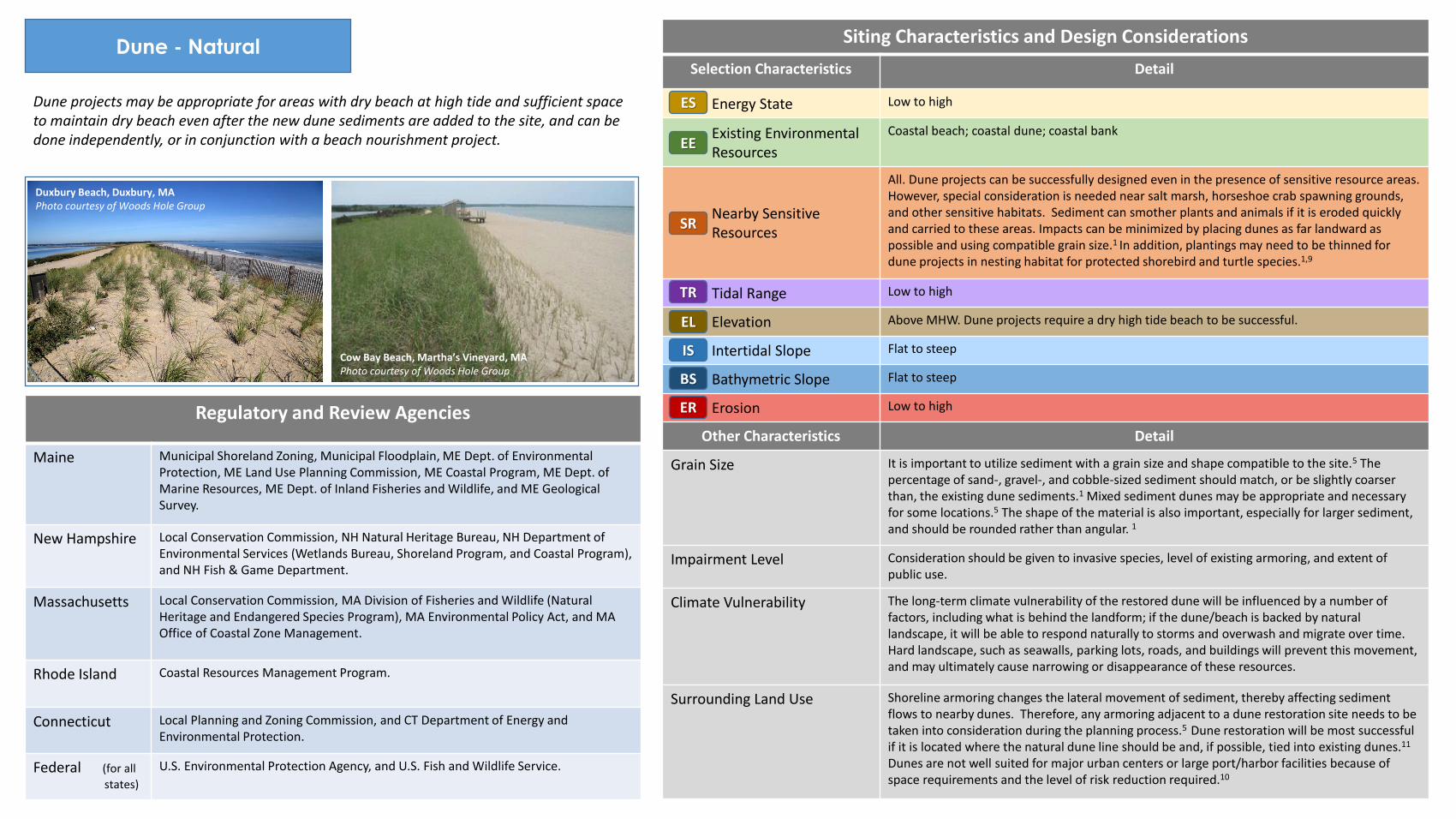
Dune projects may be appropriate for areas with dry beach at high tide and sufficient space to maintain dry beach even after the new dune sediments are added to the site, and can be done independently, or in conjunction with a beach nourishment project.
PHOTOGRAPHS (including natural examples of living shoreline types)
Siting Characteristics and Design Considerations
Selection Characteristics Detail
Energy State Low to high
Existing Environmental Resources
Coastal beach; coastal dune; coastal bank
Nearby Sensitive Resources
All. Dune projects can be successfully designed even in the presence of sensitive resource areas. However, special consideration is needed near salt marsh, horseshoe crab spawning grounds, and other sensitive habitats. Sediment can smother plants and animals if it is eroded quickly and carried to these areas. Impacts can be minimized by placing dunes as far landward as possible and using compatible grain size.1 In addition, plantings may need to be thinned for dune projects in nesting habitat for protected shorebird and turtle species.1,9
Tidal Range Low to high
Elevation Above MHW. Dune projects require a dry high tide beach to be successful.
Intertidal Slope Flat to steep
Bathymetric Slope Flat to steep
Erosion Low to high
Other Characteristics Detail
Grain Size It is important to utilize sediment with a grain size and shape compatible to the site.5 The percentage of sand-, gravel-, and cobble-sized sediment should match, or be slightly coarser than, the existing dune sediments.1 Mixed sediment dunes may be appropriate and necessary for some locations.5 The shape of the material is also important, especially for larger sediment, and should be rounded rather than angular. 1
Impairment Level Consideration should be given to invasive species, level of existing armoring, and extent of public use.
Climate Vulnerability The long-term climate vulnerability of the restored dune will be influenced by a number of factors, including what is behind the landform; if the dune/beach is backed by natural landscape, it will be able to respond naturally to storms and overwash and migrate over time. Hard landscape, such as seawalls, parking lots, roads, and buildings will prevent this movement, and may ultimately cause narrowing or disappearance of these resources.
Surrounding Land Use Shoreline armoring changes the lateral movement of sediment, thereby affecting sediment flows to nearby dunes. Therefore, any armoring adjacent to a dune restoration site needs to be taken into consideration during the planning process.5 Dune restoration will be most successful if it is located where the natural dune line should be and, if possible, tied into existing dunes.11 Dunes are not well suited for major urban centers or large port/harbor facilities because of space requirements and the level of risk reduction required.10
Regulatory and Review Agencies
Maine Municipal Shoreland Zoning, Municipal Floodplain, ME Dept. of Environmental Protection, ME Land Use Planning Commission, ME Coastal Program, ME Dept. of Marine Resources, ME Dept. of Inland Fisheries and Wildlife, and ME Geological Survey.
New Hampshire Local Conservation Commission, NH Natural Heritage Bureau, NH Department of Environmental Services (Wetlands Bureau, Shoreland Program, and Coastal Program), and NH Fish & Game Department.
Massachusetts Local Conservation Commission, MA Division of Fisheries and Wildlife (Natural Heritage and Endangered Species Program), MA Environmental Policy Act, and MA Office of Coastal Zone Management.
Rhode Island Coastal Resources Management Program.
Connecticut Local Planning and Zoning Commission, and CT Department of Energy and Environmental Protection.
Federal (for all
states)
U.S. Environmental Protection Agency, and U.S. Fish and Wildlife Service.
ES
EE
SR
TR
EL
IS
BS
ER
Cow Bay Beach, Martha’s Vineyard, MA Photo courtesy of Woods Hole Group
Duxbury Beach, Duxbury, MA Photo courtesy of Woods Hole Group
Dune - Engineered Core
Design Schematics
COST
Overview of Technique
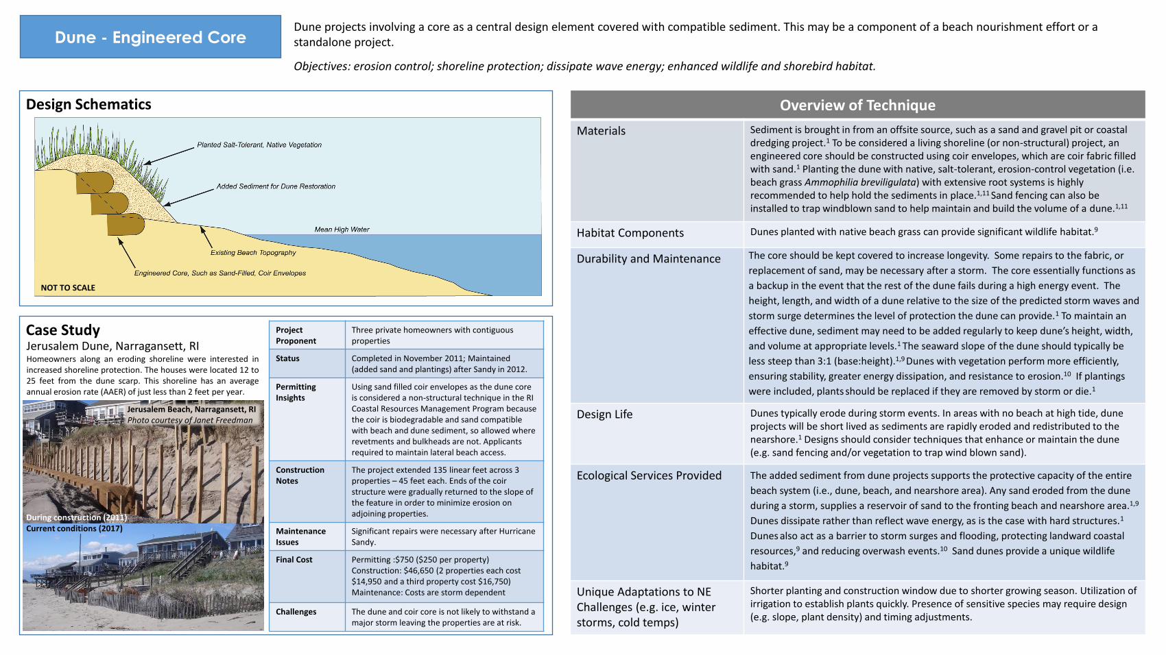
Materials Sediment is brought in from an offsite source, such as a sand and gravel pit or coastal dredging project.1 To be considered a living shoreline (or non-structural) project, an engineered core should be constructed using coir envelopes, which are coir fabric filled with sand.1 Planting the dune with native, salt-tolerant, erosion-control vegetation (i.e. beach grass Ammophilia breviligulata) with extensive root systems is highly recommended to help hold the sediments in place.1,11 Sand fencing can also be installed to trap windblown sand to help maintain and build the volume of a dune.1,11
Habitat Components Dunes planted with native beach grass can provide significant wildlife habitat.9
Durability and Maintenance The core should be kept covered to increase longevity. Some repairs to the fabric, or
replacement of sand, may be necessary after a storm. The core essentially functions as
a backup in the event that the rest of the dune fails during a high energy event. The
height, length, and width of a dune relative to the size of the predicted storm waves and
storm surge determines the level of protection the dune can provide.1 To maintain an
effective dune, sediment may need to be added regularly to keep dune’s height, width,
and volume at appropriate levels.1 The seaward slope of the dune should typically be
less steep than 3:1 (base:height).1,9 Dunes with vegetation perform more efficiently,
ensuring stability, greater energy dissipation, and resistance to erosion.10 If plantings
were included, plants should be replaced if they are removed by storm or die.1
Design Life Dunes typically erode during storm events. In areas with no beach at high tide, dune projects will be short lived as sediments are rapidly eroded and redistributed to the nearshore.1 Designs should consider techniques that enhance or maintain the dune (e.g. sand fencing and/or vegetation to trap wind blown sand).
Ecological Services Provided The added sediment from dune projects supports the protective capacity of the entire
beach system (i.e., dune, beach, and nearshore area). Any sand eroded from the dune
during a storm, supplies a reservoir of sand to the fronting beach and nearshore area.1,9
Dunes dissipate rather than reflect wave energy, as is the case with hard structures.1
Dunes also act as a barrier to storm surges and flooding, protecting landward coastal
resources,9 and reducing overwash events.10 Sand dunes provide a unique wildlife
habitat.9
Unique Adaptations to NE Challenges (e.g. ice, winter storms, cold temps)
Shorter planting and construction window due to shorter growing season. Utilization of irrigation to establish plants quickly. Presence of sensitive species may require design (e.g. slope, plant density) and timing adjustments.
Dune projects involving a core as a central design element covered with compatible sediment. This may be a component of a beach nourishment effort or a standalone project.
Objectives: erosion control; shoreline protection; dissipate wave energy; enhanced wildlife and shorebird habitat.
Case Study Project Proponent
Three private homeowners with contiguous properties
Status Completed in November 2011; Maintained (added sand and plantings) after Sandy in 2012.
Permitting Insights
Using sand filled coir envelopes as the dune core is considered a non-structural technique in the RI Coastal Resources Management Program because the coir is biodegradable and sand compatible with beach and dune sediment, so allowed where revetments and bulkheads are not. Applicants required to maintain lateral beach access.
Construction Notes
The project extended 135 linear feet across 3 properties – 45 feet each. Ends of the coir structure were gradually returned to the slope of the feature in order to minimize erosion on adjoining properties.
Maintenance Issues
Significant repairs were necessary after Hurricane Sandy.
Final Cost Permitting :$750 ($250 per property) Construction: $46,650 (2 properties each cost $14,950 and a third property cost $16,750) Maintenance: Costs are storm dependent
Challenges The dune and coir core is not likely to withstand a major storm leaving the properties are at risk.
During construction (2011) Current conditions (2017)
Jerusalem Dune, Narragansett, RI Homeowners along an eroding shoreline were interested in increased shoreline protection. The houses were located 12 to 25 feet from the dune scarp. This shoreline has an average annual erosion rate (AAER) of just less than 2 feet per year.
Jerusalem Beach, Narragansett, RI Photo courtesy of Janet Freedman
NOT TO SCALE

Dune - Engineered Core
Dune projects are appropriate for almost any area with dry beach at high tide and sufficient space to maintain some dry beach even after the new dune sediments are added to the site, and can be done independently, or in conjunction with a beach nourishment project.
PHOTOGRAPHS (including natural examples of living shoreline types)
Regulatory and Review Agencies
In general, coastal dunes with an engineered core are more difficult to permit than natural dunes.
Maine Municipal Shoreland Zoning, Municipal Floodplain, ME Dept. of Environmental Protection, ME Land Use Planning Commission, ME Coastal Program, ME Dept. of Marine Resources, ME Dept. of Inland Fisheries and Wildlife, and ME Geological Survey.
New Hampshire Local Conservation Commission, NH Natural Heritage Bureau, NH Department of Environmental Services (Wetlands Bureau, Shoreland Program, and Coastal Program), and NH Fish & Game Department.
Massachusetts Local Conservation Commission, MA Division of Fisheries and Wildlife (Natural Heritage and Endangered Species Program), MA Environmental Policy Act, and MA Office of Coastal Zone Management.
Rhode Island Coastal Resources Management Program.
Connecticut Local Planning and Zoning Commission, and CT Department of Energy and Environmental Protection.
Federal (for all
states)
U.S. Environmental Protection Agency, and U.S. Fish and Wildlife Service.
Siting Characteristics and Design Considerations
Selection Characteristics Detail
Energy State Only applicable in moderate to high energy environments. Natural dune projects are preferred whenever possible.
Existing Environmental Resources
Coastal beach; coastal dune; coastal bank
Nearby Sensitive Resources
All. Dune projects can be successfully designed even in the presence of sensitive resource areas. However, special consideration is needed near salt marsh, horseshoe crab spawning grounds, and other sensitive habitats. Sediment can smother plants and animals if it is eroded quickly and carried to these areas. Impacts can be minimized by placing dunes as far landward as possible and using compatible grain size.1 In addition, plantings may need to be thinned for dune projects in nesting habitat for protected shorebird and turtle species.1,9
Tidal Range Low to high
Elevation Above MHW. Dune projects require a dry high tide beach to be successful.
Intertidal Slope Flat to steep
Bathymetric Slope Flat to steep
Erosion Moderate to high
Other Characteristics Detail
Grain Size It is important to utilize sediment with a grain size and shape compatible to the site.5 The percentage of sand-, gravel-, and cobble-sized sediment should match, or be slightly coarser than, the existing dune sediments.1 Mixed sediment dunes may be appropriate and necessary for some locations.5 The shape of the material is also important, especially for larger sediment, and should be rounded rather than angular. 1
Impairment Level Consideration should be given to invasive species, level of existing armoring, and extent of public use.
Climate Vulnerability Dunes with an engineered core provide more stability and protection to landward areas in the short term, but do not allow the dune to migrate naturally, which may be necessary given increased storms and sea level rise in the future.
Surrounding Land Use Shoreline armoring changes the lateral movement of sediment, thereby affecting sediment flows to nearby dunes. Therefore, any armoring adjacent to a dune restoration site needs to be taken into consideration during the planning process.5 Dune restoration will be most successful if it is located where the natural dune line should be and, if possible, tied into existing dunes.11 Dunes are not well suited for major urban centers or large port/harbor facilities because of space requirements and the level of risk reduction required.10
ES
EE
SR
TR
EL
IS
BS
ER
Dune with an engineered core, South Kingstown, RI Photo courtesy of Janet Freedman

Beach Nourishment
Design Schematics Design Overview
Materials Sediment is brought in from an offsite source, such as a sand and gravel pit or coastal dredging project.1
Habitat Components Beaches nourished with compatible sediments can provide significant wildlife habitat.5,6
Durability and Maintenance A coarser sand may erode more slowly than a finer sand.6 To maintain an effective
beach berm, sediment may need to be added regularly maintain the desired beach
profile.6,11 The need to replenish the beach depends upon the rate of erosion at the
particular site, but is typically once every 1-5 years.6
Design Life To increase erosion and flooding protection, nourished beaches are frequently built higher and wider than would occur naturally.11 Grain size (e.g. sand, gravel, cobble) drives appropriate design slopes; gentler slopes generally perform better than steep areas. However, coarser grain sizes allow for steeper project slopes.
Ecological Services Provided A nourishment beach can provide additional beach habitat area. Added sediment used
for the nourishment can also provide a sand source for surrounding areas. The
increased width and height of the beach berm can help attenuate wave energy.10
Unique Adaptations to NE Challenges (e.g. ice, winter storms, cold temps)
Beach nourishment sites subject to ice impacts are generally most successfully stabilized with gentler slopes (e.g., 6:1-10:1).13 Presence of sensitive species may require design (e.g. slope, plant density) and timing adjustments.
Winthrop, MA Beach Nourishment Applied Coastal Research & Engineering, Inc. designed the Winthrop Beach Nourishment Program to provide storm protection to an upland urban area fronted by a seawall originally constructed in 1899. The project utilized 460,000 cy of compatible sediment to nourish approximately 4,200 linear feet and to create the equilibrated designed berm width of 100 feet. Once the beach nourishment was completed in late 2014, the high tide shoreline was pushed more than 150 feet from the seawall, with a gradual slope extending
approximately 350 feet offshore.
Beach nourishment is the placement of sediment along the shoreline of an eroding beach from outside source. It widens and/or elevates the beach and usually moves the shoreline seaward, increasing the natural protection that a beach can provide against wave energy and storms. This may be a component of a dune restoration/creation effort or a stand alone project.
Objectives: erosion control; shoreline protection; enhance recreation; increased access; dissipate wave energy; enhanced wildlife and shorebird habitat.
Case Study Project Proponent
Massachusetts Division of Conservation and Recreation (DCR)
Status Phase 1: 2013; Phase 2: 2014
Permitting Insights
Offshore sediment source was denied by Army Corps after a 12-year permitting process. Conservation Permit required from NHESP to address potential impacts to Piping Plovers.
Construction Notes
Upland derived mix of sand, gravel and cobble to match the existing beach sediments was required, where the nourishment was provided from two sources: sand borrow (80%) and naturally rounded cobble & gravel (20%).
Maintenance Issues
Cobble berms have begun forming along the beach, which conflicts with community recreation goals, requiring additional sand for aestheitcs.
Final Cost Permitting: $2,000,000 (including attempt to permit offshore borrow site. Construction: $22,000,000 (included work on coastal engineering structures).
Challenges Trucking through the community: urban community with two roads in and out, as well as roadway damage and air quality impacts associated with 16,000+ truck trips. Public perception of compatible sediment.
Winthrop Shores, Winthrop, MA Photo courtesy of Applied Coastal Research & Engineering
Long Beach, Barnstable, MA Photo courtesy of MA CZM
Revere Beach, MA Photo courtesy of MA CZM
NOT TO SCALE
Beach Nourishment
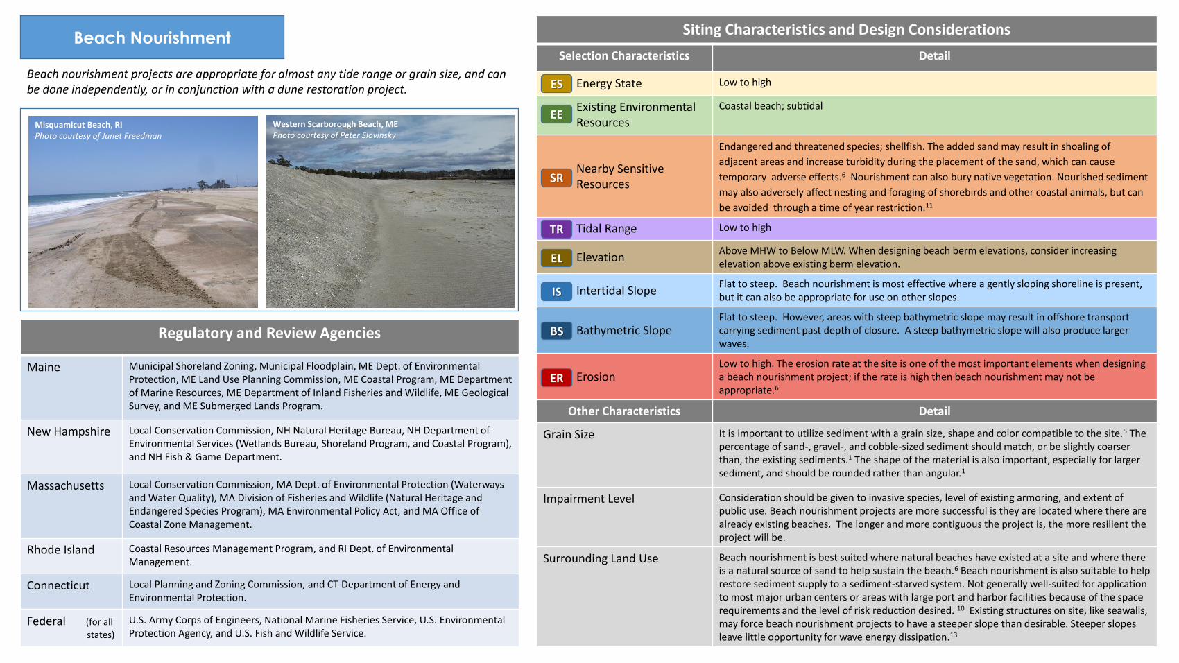
Beach nourishment projects are appropriate for almost any tide range or grain size, and can be done independently, or in conjunction with a dune restoration project.
Regulatory and Review Agencies
Maine Municipal Shoreland Zoning, Municipal Floodplain, ME Dept. of Environmental Protection, ME Land Use Planning Commission, ME Coastal Program, ME Department of Marine Resources, ME Department of Inland Fisheries and Wildlife, ME Geological Survey, and ME Submerged Lands Program.
New Hampshire Local Conservation Commission, NH Natural Heritage Bureau, NH Department of Environmental Services (Wetlands Bureau, Shoreland Program, and Coastal Program), and NH Fish & Game Department.
Massachusetts Local Conservation Commission, MA Dept. of Environmental Protection (Waterways and Water Quality), MA Division of Fisheries and Wildlife (Natural Heritage and Endangered Species Program), MA Environmental Policy Act, and MA Office of Coastal Zone Management.
Rhode Island Coastal Resources Management Program, and RI Dept. of Environmental Management.
Connecticut Local Planning and Zoning Commission, and CT Department of Energy and Environmental Protection.
Federal (for all
states)
U.S. Army Corps of Engineers, National Marine Fisheries Service, U.S. Environmental Protection Agency, and U.S. Fish and Wildlife Service.
Siting Characteristics and Design Considerations
Selection Characteristics Detail
Energy State Low to high
Existing Environmental Resources
Coastal beach; subtidal
Nearby Sensitive Resources
Endangered and threatened species; shellfish. The added sand may result in shoaling of
adjacent areas and increase turbidity during the placement of the sand, which can cause
temporary adverse effects.6 Nourishment can also bury native vegetation. Nourished sediment
may also adversely affect nesting and foraging of shorebirds and other coastal animals, but can
be avoided through a time of year restriction.11
Tidal Range Low to high
Elevation Above MHW to Below MLW. When designing beach berm elevations, consider increasing elevation above existing berm elevation.
Intertidal Slope Flat to steep. Beach nourishment is most effective where a gently sloping shoreline is present, but it can also be appropriate for use on other slopes.
Bathymetric Slope Flat to steep. However, areas with steep bathymetric slope may result in offshore transport carrying sediment past depth of closure. A steep bathymetric slope will also produce larger waves.
Erosion Low to high. The erosion rate at the site is one of the most important elements when designing a beach nourishment project; if the rate is high then beach nourishment may not be appropriate.6
Other Characteristics Detail
Grain Size It is important to utilize sediment with a grain size, shape and color compatible to the site.5 The percentage of sand-, gravel-, and cobble-sized sediment should match, or be slightly coarser than, the existing sediments.1 The shape of the material is also important, especially for larger sediment, and should be rounded rather than angular.1
Impairment Level Consideration should be given to invasive species, level of existing armoring, and extent of public use. Beach nourishment projects are more successful is they are located where there are already existing beaches. The longer and more contiguous the project is, the more resilient the project will be.
Surrounding Land Use Beach nourishment is best suited where natural beaches have existed at a site and where there is a natural source of sand to help sustain the beach.6 Beach nourishment is also suitable to help restore sediment supply to a sediment-starved system. Not generally well-suited for application to most major urban centers or areas with large port and harbor facilities because of the space requirements and the level of risk reduction desired. 10 Existing structures on site, like seawalls, may force beach nourishment projects to have a steeper slope than desirable. Steeper slopes leave little opportunity for wave energy dissipation.13
ES
EE
SR
TR
EL
IS
BS
ER
Misquamicut Beach, RI Photo courtesy of Janet Freedman
Western Scarborough Beach, ME Photo courtesy of Peter Slovinsky

Coastal Bank - Natural
Design Schematics Overview of Technique
Materials Sediment, if fill is needed, to establish a stable slope. Coir rolls or root wads from fallen trees to minimize erosion. Coir rolls, typically rolls 12-20” in diameter and 10-20 feet long, packed with coir fibers and held together by mesh.1 (Coir rolls can be pre-vegetated to head start the growing process.) A high-density roll may be necessary at the toe, while lower-density rolls could be used above.5 Wooden stakes for blankets, earth anchors for rolls, or a combination of the two are necessary to anchor the system.1 Other naturally occurring woody material or root wads may also be utilized to stabilize the toe of the coastal bank in some sites. Salt-tolerant vegetation with extensive root systems are often used in conjunction with fiber rolls to help stabilize the site.1 Natural fiber blankets can be used to stabilize the ground surface while plants become established.1 (Blankets should be run up and down the slope rather than horizontally across it.)
Habitat Components Because they are made with natural fibers and planted with vegetation, natural fiber blankets also help preserve the natural character and habitat value of the coastal environment.1
Durability and Maintenance Installing coir rolls at the toe of a bank stabilization project can provide increased
stability while the vegetation becomes established,1 but bioengineering projects with
coir rolls and vegetation require ongoing maintenance, such as resetting, anchoring, or
replacement, to ensure their success.1,6 Coir logs must be securely anchored to prevent
wave and tidal current-induced movement.11 Invasive species management should be
incorporated into the project.1 Runoff and groundwater management will also be crucial
to project success.6
Design Life As the coir rolls disintegrate, typically over 5-7 years, the plants take over the job of site stabilization.1 The bank slope is extremely important. Often the existing condition of the slope is steep or undercut. Before installing coir logs or planting vegetation, the bank slope should be stabilized.1 This is often done by regrading the bank slope by removal of sediment from the top of the bank rather than adding sediment to the toe of the slope.1
Ecological Services Provided Upland plantings stabilize bluffs and reduce rainwater runoff.11
Unique Adaptations to NE Challenges (e.g. ice, winter storms, cold temps)
Shorter planting and construction window due to shorter growing season. Utilization of irrigation to establish plants quickly. Freeze and thaw processes can damage this design. Consideration should be given to the slope aspect and the implications on plant growth and microbiome from shading and sun exposure.
Coastal Bank Stabilization, Orleans, MA Wilkinson Ecological Design developed a plant-focused coastal bioengineering project, determined not to be a coastal engineering structure by the local municipality and MA DEP. The project included a robustly anchored fiber roll array at the bottom of the bank and intensive planting and stabilization through the remainder of their coastal bank, which falls within a mapped FEMA Velocity Zone.
Coastal bank protection, including slope grading, and toe protection and planting of natural vegetation will reduce the steepness and protect the toe of the bank from further erosion. Coir logs, root wads protect bank toes from erosion, while planted vegetation develops strong root systems.
Objectives: erosion control; shoreline protection; dissipate wave energy; enhanced wildlife habitat.
Project Proponent
Private property owners. The project spans three properties with multiple owners.
Status Phase 1 constructed in 2010, Phase 2 constructed in 2013 and Phase 3 constructed in 2015.
Permitting Insights
The project involved one permit under the MA Wetlands Protection Act for each phase, three wetland permits in total.
Construction Notes
Regraded the over steepened bank, installed six rows of coir rolls at the toe of bank, installed natural fiber blankets on the bank face above the coir rolls, planted the bank face with native, salt-tolerant grasses and shrubs, and covered fiber rolls with sand.
Maintenance Issues
Monitor vegetation monthly throughout the growing season to ensure plant success; temp-orary irrigation for first three years; monitor coir rolls twice annually and after storms. Replant and retighten fiber roll anchoring system as needed.
Final Cost Permitting: $10,000 Construction: $1,000/ linear foot Maintenance : $8,000/yr
Challenges No substantial challenges in the permitting, construction or maintenance phases of work and has performed well through storms.
Case Study
Pleasant Bay Bank Stabilization, Orleans, MA Photos courtesy of Wilkinson Ecological Design
NOT TO SCALE
Coastal Bank - Natural
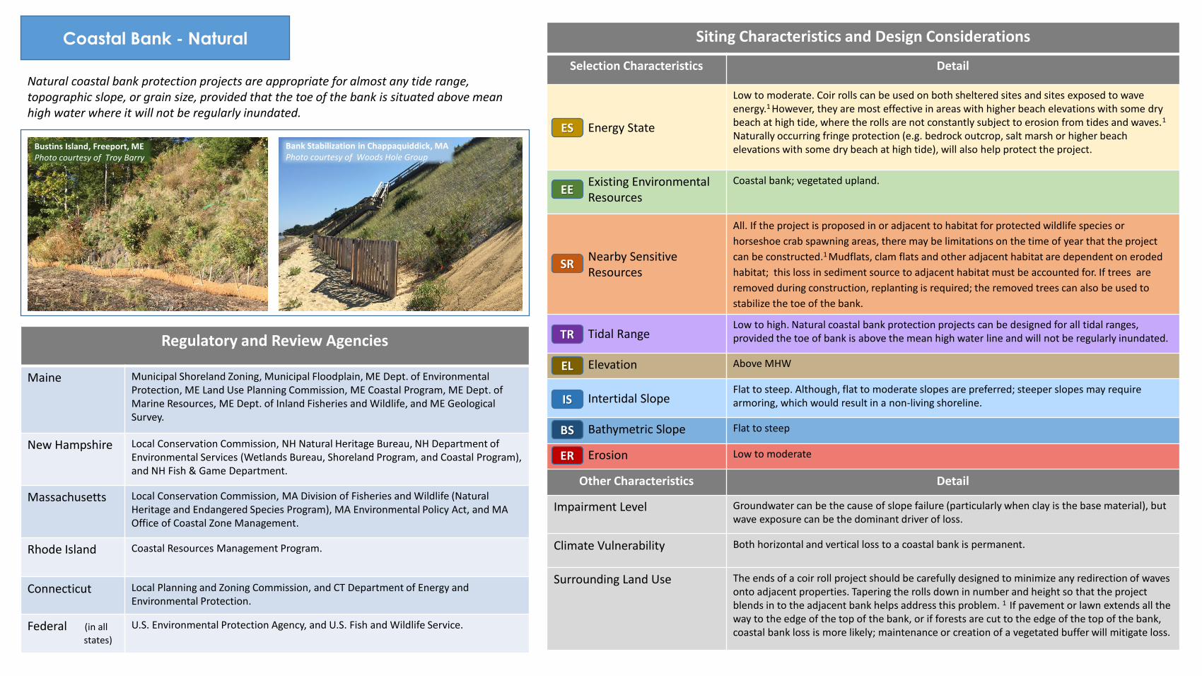
Natural coastal bank protection projects are appropriate for almost any tide range, topographic slope, or grain size, provided that the toe of the bank is situated above mean high water where it will not be regularly inundated.
Siting Characteristics and Design Considerations
Selection Characteristics Detail
Energy State
Low to moderate. Coir rolls can be used on both sheltered sites and sites exposed to wave energy.1 However, they are most effective in areas with higher beach elevations with some dry beach at high tide, where the rolls are not constantly subject to erosion from tides and waves.1 Naturally occurring fringe protection (e.g. bedrock outcrop, salt marsh or higher beach elevations with some dry beach at high tide), will also help protect the project.
Existing Environmental Resources
Coastal bank; vegetated upland.
Nearby Sensitive Resources
All. If the project is proposed in or adjacent to habitat for protected wildlife species or
horseshoe crab spawning areas, there may be limitations on the time of year that the project
can be constructed.1 Mudflats, clam flats and other adjacent habitat are dependent on eroded
habitat; this loss in sediment source to adjacent habitat must be accounted for. If trees are
removed during construction, replanting is required; the removed trees can also be used to
stabilize the toe of the bank.
Tidal Range Low to high. Natural coastal bank protection projects can be designed for all tidal ranges, provided the toe of bank is above the mean high water line and will not be regularly inundated.
Elevation Above MHW
Intertidal Slope Flat to steep. Although, flat to moderate slopes are preferred; steeper slopes may require armoring, which would result in a non-living shoreline.
Bathymetric Slope Flat to steep
Erosion Low to moderate
Other Characteristics Detail
Impairment Level Groundwater can be the cause of slope failure (particularly when clay is the base material), but wave exposure can be the dominant driver of loss.
Climate Vulnerability Both horizontal and vertical loss to a coastal bank is permanent.
Surrounding Land Use The ends of a coir roll project should be carefully designed to minimize any redirection of waves onto adjacent properties. Tapering the rolls down in number and height so that the project blends in to the adjacent bank helps address this problem. 1 If pavement or lawn extends all the way to the edge of the top of the bank, or if forests are cut to the edge of the top of the bank, coastal bank loss is more likely; maintenance or creation of a vegetated buffer will mitigate loss.
ES
EE
SR
TR
EL
IS
BS
ER
Regulatory and Review Agencies
Maine Municipal Shoreland Zoning, Municipal Floodplain, ME Dept. of Environmental Protection, ME Land Use Planning Commission, ME Coastal Program, ME Dept. of Marine Resources, ME Dept. of Inland Fisheries and Wildlife, and ME Geological Survey.
New Hampshire Local Conservation Commission, NH Natural Heritage Bureau, NH Department of Environmental Services (Wetlands Bureau, Shoreland Program, and Coastal Program), and NH Fish & Game Department.
Massachusetts Local Conservation Commission, MA Division of Fisheries and Wildlife (Natural Heritage and Endangered Species Program), MA Environmental Policy Act, and MA Office of Coastal Zone Management.
Rhode Island Coastal Resources Management Program.
Connecticut Local Planning and Zoning Commission, and CT Department of Energy and Environmental Protection.
Federal (in all
states)
U.S. Environmental Protection Agency, and U.S. Fish and Wildlife Service.
Bustins Island, Freeport, ME Photo courtesy of Troy Barry
Bank Stabilization in Chappaquiddick, MA Photo courtesy of Woods Hole Group

Stillhouse Cove, Cranston, RI Stillhouse Cove is the site of a public park and a previous salt marsh restoration project that was completed in 2007. Restoration of the coastal bank was initiated after Superstorm Sandy caused extensive erosion which over-steepened the bank and washed fill and soil into the adjacent marsh. Save The Bay and EWPA, working closely with the USDA Natural Resources Conservation Service, developed a design to reinforce and protect the eroding bank by reconfiguring the slope and using natural materials and vegetation.
Coastal Bank –
Engineered Core
PHOTOGRAPHS (including natural examples of living shoreline types)
Design Schematics Design Overview
Materials An engineered core could be constructed using coir envelopes, which are coir fabric
filled with sand. Cutback/excavated material should be used to fill the coir envelopes
but supplemental offsite material may be required. Anchors are necessary to secure
the envelopes. Native vegetation with extensive root systems are often used in
conjunction with coir envelopes to help stabilize the site. Also, natural fiber blankets
can also be used to stabilize the ground surface while plants become established.
(Blankets should be run up and down the slope rather than horizontally across it.)
Habitat Components Because they are made with natural fibers and planted with vegetation, natural fiber blankets also help preserve the natural character and habitat value of the coastal environment.
Durability and Maintenance A veneer of sand/sediment should be maintained over the sand filled tubes to prolong
their lifetime. Regular maintenance, such as resetting, anchoring, replacement, or
recovering, can increase the effectiveness of the project.6 Invasive species management
should be incorporated into the project. Runoff management and groundwater will also
be crucial to project success.6
Design Life As the sand tube material and natural fiber blankets disintegrate, typically over 5-10
years, the plants take over the job of site stabilization.
Ecological Services Provided Upland plantings stabilize bluffs and reduce rainwater runoff.11
Unique Adaptations to NE Challenges (e.g. ice, winter storms, cold temps)
Shorter planting and construction window due to shorter growing season. Utilization of irrigation to establish plants quickly. Freeze and thaw processes can damage this design. Consideration should be given to the slope aspect and the implications on plant growth and microbiome from shading and sun exposure.
Coastal bank protection, including slope grading, terracing, and toe protection and vegetation planting will reduce the steepness and protect the toe of the bank from further erosion. Engineered cores, of sand filled tubes, provide added protection from future bank erosion.
Objectives: erosion control; shoreline protection; dissipate wave energy; enhanced wildlife habitat.
NEED PHOTOS
Case Study Project Proponent
City of Cranston, RI, Edgewood Waterfront Preservation Association (EWPA), Save The Bay, Natural Resources Conservation Service (NRCS).
Status Completed in 2013. Maintained in 2014 (added coir logs and plantings).
Permitting Insights
The project had several iterations but was finally permitted as a Sandy Emergency Assent. An extension was required due to challenges of securing funding within the permit time frame.
Construction Notes
A key component of this project was regrading the bank from a vertical cut to create a more gradual slope. Once the slope was regraded, sand filled coir envelopes were installed, covered with soil and planted with salt tolerant vegetation.
Maintenance Issues
3 coir logs were installed at the southern end of project and planted with warm season grasses as part of the Dept. of Interior Hurricane Sandy Relief Grant Program. The base of the bank will be more frequently inundated as sea levels rise.
Final Cost Permitting: No permit fee for municipalities Construction: $59,006 plus volunteer labor.
Challenges Funding and coordination with partners and volunteers.
Construction at Stillhouse Cove, RI Photos courtesy of Janet Freedman
Completed Stillhouse Cove Project (RI) Photo courtesy of Janet Freedman
NOT TO SCALE
Construction at Allin’s Cove, Barrington, RI Photo courtesy of Janet Freedman

Coastal Bank –
Engineered Core
Engineered coastal bank protection projects are appropriate for almost any tide range, topographic slope, or grain size, provided that the toe of the bank is situated above mean high water where it will not be regularly inundated.
Regulatory and Review Agencies
Maine Municipal Shoreland Zoning, Municipal Floodplain, ME Dept. of Environmental Protection, ME Land Use Planning Commission, ME Coastal Program, ME Dept. of Marine Resources, ME Dept. of Inland Fisheries and Wildlife, and ME Geological Survey.
New Hampshire Local Conservation Commission, NH Natural Heritage Bureau, NH Department of Environmental Services (Wetlands Bureau, Shoreland Program, and Coastal Program), and NH Fish & Game Department.
Massachusetts Local Conservation Commission, MA Division of Fisheries and Wildlife (Natural Heritage and Endangered Species Program), MA Environmental Policy Act, and MA Office of Coastal Zone Management.
Rhode Island Coastal Resources Management Program.
Connecticut Local Planning and Zoning Commission, and CT Department of Energy and Environmental Protection.
Federal (in all
states)
U.S. Environmental Protection Agency, and U.S. Fish and Wildlife Service.
Siting Characteristics and Design Considerations
Selection Characteristics Detail
Energy State
Low to high. Engineered cores, as part of a coastal bank protection project, can be used on both sheltered sites and sites exposed to wave energy. Additionally, they are most effective in areas with naturally occurring fringe protection (e.g. bedrock outcrop, salt marsh or higher beach elevations with some dry beach at high tide), where the toe of the bank is not constantly subject to erosion from tides and waves.1
Existing Environmental Resources
Coastal bank; vegetated upland.
Nearby Sensitive Resources
All. If the project is proposed in or adjacent to habitat for protected wildlife species or
horseshoe crab spawning areas, there may be limitations on the time of year that the project
can be constructed.1 Mudflats, clam flats and other adjacent habitat are dependent on eroded
habitat; this loss in sediment source to adjacent habitat must be accounted for. If trees are
removed during construction, replanting is required; the removed trees can also be used to
stabilize the toe of the bank.
Tidal Range Low to high. An engineered coastal bank protection projects can be designed for all tidal ranges, provided the toe of bank is above the mean high water line and will not be regularly inundated.
Elevation Above MHW
Intertidal Slope Flat to steep. Although, flat to moderate slopes are preferred; steeper slopes may require armoring, which would result in a non-living shoreline.
Bathymetric Slope Flat to steep
Erosion Low to high. Steeper slopes may be more likely to erode, i.e. less stable. Coastal bank protection projects with engineered cores are preferred in areas of widespread erosion.
Other Characteristics Detail
Impairment Level Groundwater can be the cause of slope failure (particularly when clay is the base material), but wave exposure can be the dominant driver of loss.
Climate Vulnerability Both horizontal and vertical loss to a coastal bank is permanent.
Surrounding Land Use The ends of the sand tubes for an engineered coastal bank protection project should be carefully designed to minimize any redirection of waves onto adjacent properties. Tapering the tubes down in number and height so that the project blends in to the adjacent bank helps address this problem. 1 If pavement or lawn extends all the way to the edge of the top of the bank, or if forests are cut to the edge of the top of the bank, coastal bank loss is more likely; maintenance or creation of a vegetated buffer will mitigate loss.
ES
EE
SR
TR
EL
IS
BS
ER
Construction at King’s Park, Newport, RI Photos courtesy of Janet Freedman

Natural Marsh
Creation/Enhancement
PHOTOGRAPHS (including natural examples of living shoreline types)
Design Schematics Design Overview
Materials Native marsh plants appropriate for salinity and site conditions. Plugs of marsh grass
can be planted to augment bare or sparse areas.11 Sediment may be necessary if the
project area needs to be filled to obtain appropriate elevations, to provide a suitably
gradual slope for marsh creation, or to enable a marsh to maintain its elevation with
respect to the sea-level rise.11 Bird exclusion fencing may be necessary to avoid
predation while plants develop.16
Habitat Components Salt marsh; Tidal buffer landward of the salt marsh; Coastal beach; Mud flat.
Durability and Maintenance Plants that are removed or die during the early stages of growth must be replaced
immediately to ensure the undisturbed growth of the remaining plants. The removal of
debris and selective pruning of trees is also a good maintenance practice to ensure that
sunlight reaches plants. Protection measures, such as fencing, must be taken to keep
waterfowl from eating the young plants.6 Ongoing maintenance of invasive species and
runoff issues will be important to the long-term success of the project. After significant
growth has occurred only periodic inspections may be necessary.
Design Life It is important to recognize that design life may be shorter in the future given changes in
sedimentation rates, accelerating sea-level rise and other climate change impacts.
Ecological Services Provided Increases water infiltration, uptake of nutrients, filtration, denitrification and sediment
retention.2,3 The extensive root systems of marsh vegetation help to retain the existing
soil, thus reducing erosion while plant stems attenuate wave energy.11 A healthy salt
marsh may reduce wave energy. Marshes provide habitat for many species of plants
and animals, and maintain the aquatic/terrestrial interface.2 Marshes also provide
natural shore erosion control, better water quality, recreation and education
opportunities, and carbon sequestration (blue carbon).12
Unique Adaptations to NE Challenges (e.g. ice, winter storms, cold temps)
Including roughened surfaces, such as emergent vegetation can help break up ice
sheets.4 Marshes can respond better to ice if gentler slopes (6:1-10:1) are used and by
incorporating shrubs. Planting in the spring will allow vegetation time to become
established before it has to withstand ice.8,13 Consider using pre-planted mats to
compensate for a shorter growing season. Hardy, salt-tolerant shrubs (e.g., Iva
frutescens and Baccharis halimifolia) are well-suited for shorelines affected by ice.13
Marsh vegetation, such as native low (Spartina alterniflora) and high marsh (Spartina patens) species, can be planted along the shoreline. Roots help hold soil in place, and shoots will break small waves and increase sedimentation – vegetation projects such as this are a minimally invasive approach.
Objectives: dissipates wave energy, habitat creation, shoreline stabilization
Sachuest Point Restoration, Middletown, RI The U.S. Fish & Wildlife Service and The Nature Conservancy developed this project at the Sachuest Point National Wildlife Refuge to help the area better withstand the impacts of sea-level rise and coastal storm surge. Storm surge and wave erosion, combined with the lack of sediment replenishment from estuaries whose rivers have been dammed, left the existing salt marsh at a point where it could not keep up with sea-level rise. With little opportunity to migrate, due to being constrained by Third Beach, the best solution to protect Sachuest Point was to raise the elevation of the marsh itself.
Case Study Project Proponent
USFWS, The Nature Conservancy, Save The Bay, Town of Middletown, Norman Bird Sanctuary
Status Initial construction and planting: Spring 2016.
Permitting Insights
Care was taken to prevent sediment plumes from entering the Sakonnet that could negatively affect winter flounder. Testing was done to ensure material was clean and of appropriate grain size. Ensured that elevations remained within the tidal marsh elevation range.
Construction Notes
Sand was trucked to the site and placed on the marsh with machines. The surface was contoured to create high and low marsh elevations. Salt tolerant grass plugs grown out from local seed sources were planted in the spring following sediment placement.
Maintenance Issues
Fencing was used to protect plant plugs from winter grazing by Canada Geese. Additional planting will occur in 2017.
Final Cost $634,000 for sediment placement; $36,100 for growing of plant plugs.
Challenges A drought during the growing season of 2016 caused mortality of some plant plugs, and maintenance of anti-grazing fencing during/after winter storms to prevent damage by geese.
NOT TO SCALE
Sachuest Point, Middletown, RI Photo courtesy of Jennifer White

Natural Marsh
Creation/Enhancement
Fringing marsh living shoreline projects have proven successful with or without protective structures such as fiber rolls or sills, but projects without protective structures are most likely to be successful on sheltered waterways where there is low natural wave action and limited wave action from boating activities.
Regulatory and Review Agencies
Maine Municipal Shoreland Zoning, Municipal Floodplain, ME Dept. of Environmental Protection, ME Land Use Planning Commission, ME Coastal Program, ME Department of Marine Resources, ME Department of Inland Fisheries and Wildlife, ME Geological Survey, and ME Submerged Lands Program.
New Hampshire Local Conservation Commission, NH Natural Heritage Bureau, NH Department of Environmental Services (Wetlands Bureau, Shoreland Program, and Coastal Program), and NH Fish & Game Department.
Massachusetts Local Conservation Commission, MA Dept. of Environmental Protection (Waterways and Water Quality), MA Division of Fisheries and Wildlife (Natural Heritage and Endangered Species Program), MA Environmental Policy Act, and MA Office of Coastal Zone Management.
Rhode Island Coastal Resources Management Program, and RI Dept. of Environmental Management.
Connecticut Local Planning and Zoning Commission, and CT Department of Energy and Environmental Protection.
Federal (for all
states)
U.S. Army Corps of Engineers, National Marine Fisheries Service, U.S. Environmental Protection Agency, and U.S. Fish and Wildlife Service.
Siting Characteristics and Design Considerations
Selection Characteristics Detail
Energy State Low to moderate. Works best in low energy sites (i.e. less than 2 feet of short waves, low
current and low storm surge).3 Sites with a fetch >5 miles are not recommended.15
Existing Environmental Resources
Coastal beach; mud flat; salt marsh
Nearby Sensitive Resources
Endangered and threatened species. If the project is proposed in or adjacent to habitat for
protected wildlife species or horseshoe crab spawning areas, there may be limitations on the
time of year for construction.1 Shellfish beds and essential fish habitats will restrict where a
marsh can be extended. Construction may produce short term habitat impacts, but in the long
term, the marsh area should provide enhanced wildlife and fisheries habitat.
Tidal Range Low to high
Elevation MLW to MHW; Above MHW. For low marsh, the lowest grade should be MTL and extend up to MHW. High marsh plantings should extend between MHW and MHHW.5 Tidal buffer should be planted above highest observable tide.
Intertidal Slope
Flat. With slopes 5:1 (base:height) and flatter, plants can be utilized without additional erosion
control.3 Between 5:1 and 3:1, marsh projects may not work without additional toe
stabilization.3 The wider the intertidal zone, the more effective the marsh is at dissipating wave
energy.7 A minimum width of the planting should be 10 feet.15
Bathymetric Slope Flat to moderate
Erosion Low to moderate
Other Characteristics Detail
Boat Traffic If boat wakes are perceived to be a significant problem, the site should be treated as a higher energy site and may be more suitable with a sill or other toe protection.
Ice Sensitivity Planted marsh areas with gentle slopes and intermixed shrubs will handle ice the best. Shrubs have a significant advantage over other types of vegetation because they have deep fibrous root systems and a structure that remains in place throughout the winter months.8 Plant in the spring to allow plants to become established well before ice becomes a concern.8
Climate Vulnerability Planted marsh areas may have a difficult time adapting to sea level rise.7 If there is space on a project site, designs should anticipate marsh migration in response to sea level rise.13
Surrounding Land Use Existing structures on site, like seawalls, may force living shoreline projects to have a steeper slope than desirable. Seawalls will limit the inland migration potential of the salt marsh in the future. Steeper slopes leave little opportunity for wave energy dissipation.13 Marshes require sunlight to thrive; trees must be pruned or removed to allow for at least four to six hours of sunlight a day;6 this will increase vegetation growth.11,15 Although it is possible to create a marsh on most shorelines, marsh creation is not recommended for sites where they are not a natural feature along comparable natural shorelines.11
ES
EE
SR
TR
EL
IS
BS
ER
Allin’s Cove, Barrington, RI Photo courtesy of Janet Freedman
Fringing Marsh Project, Indigo Point, S. Kingstown, RI Photo courtesy of Janet Freedman

Marsh Creation/Enhancement
w/Toe Protection
PHOTOGRAPHS (including natural examples of living shoreline types)
Design Schematics Design Overview
Materials Native marsh plants appropriate for salinity and site conditions. Plugs of marsh grass
can be planted to augment bare areas.11 Sediment may be necessary if area needs to
be filled to obtain appropriate elevations. Toe protection materials may include natural
fiber rolls, oyster/mussel shells bags, or in some cases, stone. Filter cloth placed prior
to added fill and/or sill materials.16 Bird exclusion fence to avoid predation while plants
develop.16
Habitat Components Salt marsh; Tidal buffer landward of the salt marsh; Coastal beach; Mud flat.
Durability and Maintenance Plants that are removed or die during the early stages of growth must be replaced
immediately to ensure the undisturbed growth of the remaining plants. The removal of
debris and selective pruning of trees is also a good maintenance practice to ensure that
sunlight reaches plants. After significant growth has occurred only periodic inspections
may be necessary. Protection measures, such as fencing, can keep water-fowl from
eating the young plants. Toe protection materials should also be replaced or re-installed
if they are moved by a storm.6 Coir logs must be securely anchored to prevent wave
and tidal current-induced movement.11 Ongoing maintenance of invasive species and
runoff issues will be important to the long-term success of the project.10
Design Life It is important to recognize that design life may be shorter in the future given changes in
sedimentation rates, accelerating sea-level rise and other climate change impacts.
Ecological Services Provided Increases water infiltration, uptake of nutrients, filtration, denitrification and sediment
retention.2,3 The extensive root systems of marsh vegetation help to retain the existing
soil, thus reducing erosion while plant stems attenuate wave energy.11 Marshes provide
habitat for many species of plants and animals, and maintain the aquatic/terrestrial
interface.2 Sill mitigates erosive waves and stabilizes shoreline.10 Marine animals can
access the marsh through gaps in the sill.12 Marshes also provide better water quality,
recreation and education opportunities, and carbon sequestration (blue carbon).12
Unique Adaptations to NE Challenges (e.g. ice, winter storms, cold temps)
Including roughened surfaces, such as logs, stones or emergent vegetation can break up
ice sheets.4,10 Fringing marsh projects will respond better to ice if designed with gentler
slopes (6:1-10:1) and by incorporating shrubs.9,13 Planting in the spring will allow
vegetation to become established before it has to withstand ice.8 Hardy, salt-tolerant
shrubs are well-suited shorelines that are affected by ice.13 Need to consider where in
the tidal range oysters will be placed if they’re used: too high may result in freezing.
Marsh vegetation that is planted along the shoreline often benefits from toe protection to assist with marsh stabilization. Toe protection materials may include natural fiber rolls, shell bags or, in some cases, stone. The toe protection may also allow the design to achieve the appropriate grade in lieu of seaward fill, thereby decreasing the project footprint.
Objectives: dissipates wave energy, habitat creation, shoreline stabilization
North Mill Pond, Portsmouth, NH This project involved restoration of low and high marsh along North Mill Pond, with about half of the area consisting of new marsh creation, and the other half of the area consisting of restoration of degraded low and high marsh through sediment addition (thin layer deposition).
Case Study Project Proponent
City of Portsmouth, Stantec (wetlands consultant), UNH (assisted plan development)
Status Construction complete May 2016. Beginning year two of monitoring in 2017.
Permitting Insights
NHDES and USACOE permits needed for drainage outfall into pond. Project impacted 600 sf of coastal wetland. Salt marsh restoration was compensatory mitigation.
Construction Notes
Imported fill to raise 12,060 sf to suitable elevation for salt marsh (low marsh); planted 3,055 sf of high marsh area. Created micro-topography and interior drainage channels. 12-in diameter coir logs staked at seaward edge of marsh to stabilize toe. Placed large boulders to break-up winter ice sheets.
Maintenance Issues
Long term monitoring and maintenance efforts are scheduled. Survival of low marsh plants is good; survival of high marsh salt hay is fair to poor. Survived 2016-2017 winter well.
Final Cost $60,000 (construction, monitoring & maintenance)
Challenges Construction did not have a provision for within plot drainage; many plants were washed out by runoff gullies in the first year. More time needed for filled sediment to settle before planting.
North Mill Pond Marsh Restoration, Portsmouth, NH Photo courtesy of David Burdick (UNH)
NOT TO SCALE
Marsh Creation/Enhancement
w/Toe Protection
Regulatory and Review Agencies
Maine Municipal Shoreland Zoning, Municipal Floodplain, ME Dept. of Environmental Protection, ME Land Use Planning Commission, ME Coastal Program, ME Department of Marine Resources, ME Department of Inland Fisheries and Wildlife, ME Geological Survey, and ME Submerged Lands Program.
New Hampshire Local Conservation Commission, NH Natural Heritage Bureau, NH Department of Environmental Services (Wetlands Bureau, Shoreland Program, and Coastal Program), and NH Fish & Game Department.
Massachusetts Local Conservation Commission, MA Dept. of Environmental Protection (Waterways and Water Quality), MA Division of Fisheries and Wildlife (Natural Heritage and Endangered Species Program), MA Environmental Policy Act, and MA Office of Coastal Zone Management.
Rhode Island Coastal Resources Management Program, and RI Dept. of Environmental Management.
Connecticut Local Planning and Zoning Commission, and CT Department of Energy and Environmental Protection.
Federal (for all
states)
U.S. Army Corps of Engineers, National Marine Fisheries Service, U.S. Environmental Protection Agency, and U.S. Fish and Wildlife Service.
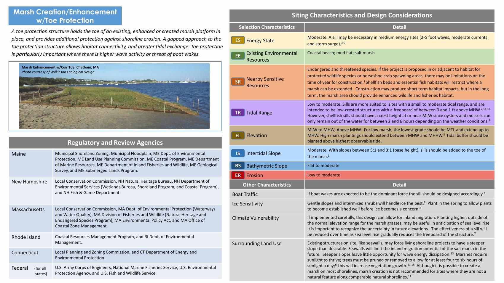
A toe protection structure holds the toe of an existing, enhanced or created marsh platform in
place, and provides additional protection against shoreline erosion. A gapped approach to the
toe protection structure allows habitat connectivity, and greater tidal exchange. Toe protection
is particularly important where there is higher wave activity or threat of boat wakes.
Siting Characteristics and Design Considerations
Selection Characteristics Detail
Energy State Moderate. A sill may be necessary in medium energy sites (2-5 foot waves, moderate currents
and storm surge).3,6
Existing Environmental Resources
Coastal beach; mud flat; salt marsh
Nearby Sensitive Resources
Endangered and threatened species. If the project is proposed in or adjacent to habitat for
protected wildlife species or horseshoe crab spawning areas, there may be limitations on the
time of year for construction.1 Shellfish beds and essential fish habitats will restrict where a
marsh can be extended. Construction may produce short term habitat impacts, but in the long
term, the marsh area should provide enhanced wildlife and fisheries habitat.
Tidal Range
Low to moderate. Sills are more suited to sites with a small to moderate tidal range, and are intended to be low-crested structures with a freeboard of between 0 and 1 ft above MHW.7,11,16 However, shellfish sills should have a crest height at or near MLW since oysters and mussels can only remain out of the water for between 2 and 6 hours depending on the weather conditions.7
Elevation MLW to MHW; Above MHW. For low marsh, the lowest grade should be MTL and extend up to MHW. High marsh plantings should extend between MHW and MHHW.5 Tidal buffer should be planted above highest observable tide.
Intertidal Slope Moderate. With slopes between 5:1 and 3:1 (base:height), sills should be added to the toe of
the marsh.3
Bathymetric Slope Flat to moderate
Erosion Low to moderate
Other Characteristics Detail
Boat Traffic If boat wakes are expected to be the dominant force the sill should be designed accordingly.7
Ice Sensitivity Gentle slopes and intermixed shrubs will handle ice the best.8 Plant in the spring to allow plants to become established well before ice becomes a concern.8
Climate Vulnerability If implemented carefully, this design can allow for inland migration. Planting higher, outside of the normal elevation range for the marsh grasses, may be useful in anticipation of sea level rise. It is important to recognize the uncertainty in future elevations. The effectiveness of a sill will be reduced over time as sea level rise gradually reduces the freeboard of the structure.7
Surrounding Land Use Existing structures on site, like seawalls, may force living shoreline projects to have a steeper slope than desirable. Seawalls will limit the inland migration potential of the salt marsh in the future. Steeper slopes leave little opportunity for wave energy dissipation.13 Marshes require sunlight to thrive; trees must be pruned or removed to allow for at least four to six hours of sunlight a day;6, this will increase vegetation growth.11,15 Although it is possible to create a marsh on most shorelines, marsh creation is not recommended for sites where they are not a natural feature along comparable natural shorelines.11
ES
EE
SR
TR
EL
IS
BS
ER
Marsh Enhancement w/Coir Toe, Chatham, MA Photo courtesy of Wilkinson Ecological Design

Living Breakwater
PHOTOGRAPHS (including natural examples of living shoreline types)
Design Schematics Design Overview
Materials Living reef materials (oysters/mussels). Shellfish reefs can be constructed with bagged
or loose shell to provide the same erosion control as rock sills but with additional
ecosystem benefits.11 Precast concrete forms or stone.
Habitat Components Shellfish reef. Complex structure for fisheries habitat.
Durability and Maintenance Concrete reefs or living resources (e.g. shell bags) will break down over time, while
precast concrete forms and stone will last longer. The degradation of the shell bags over
time is often a desired characteristic if they are being used to temporarily break waves
while a system behind it is reestablishing or a natural living system is establishing itself
on this substrate.
Design Life Shell bags, concrete forms, and stone provide the foundation for living breakwaters;
concrete forms and stone provide more time for natural recruitment of shellfish and
marine algae.
Ecological Services Provided Can become valuable substrate for marine organisms, as well as provide shelter and
habitat for many fish, crab and other mobile species.14 Can dampen wave energies and
increase sediment retention.10 Because shellfish are filter feeders, oyster/mussel reefs
can improve water quality.11 As the living breakwaters become colonized with marine
species, they provide recreational benefits such as fishing and snorkeling.11
Unique Adaptations to NE Challenges (e.g. ice, winter storms, cold temps)
Reef Balls installed in Stratford, CT withstood significant icing during the 2014-2015
winter.14 Need to consider where in the tidal range shellfish will be placed if they’re
used: too high in the intertidal area may result in freezing and loss of shellfish.
Living breakwaters are constructed nearshore to break waves on the structure rather than on the shoreline to reduce erosion and promote accumulation of sand and gravel landward of the structure. They are typically larger than sills and constructed in deeper water in more energetic wave climates, and have the potential to enhance habitat.
Objectives: break waves, dissipates wave energy, erosion control, habitat creation
Stratford, CT Reef Balls Beginning in 2010, the Stratford Point project has focused on restoring and managing 28 acres of coastal upland and 12 acres of intertidal habitat using an integrated whole ecosystem approach. The creation of a 1,000-foot living shoreline started with the construction of an artificial reef, using pre-cast reef balls, at mean tide elevation (~ 75 ft. offshore), in conjunction with restoration of low and high marshes and dune shoreward of the artificial reef. In addition, upland shrub, coastal forest and meadow mosaic is being restored to improve bird and pollinator habitat.
Case Study Project Proponents
Sacred Heart Uni.(Project Lead), Audubon Society (Site Manager); DuPont Company (Site Owner)
Status In Progress (Reef construction: Complete; Marsh & Dune Restoration and Upland work: Continuing
Permitting Insights
DABA had concerns about ‘wild’ oysters settling on the reef and possibly harboring diseases that might affect the aquaculture industry of Long Island Sound. So far, this has not been a problem.
Construction Notes
A restoration team of land managers, restoration ecologists and environmental engineers is key for designing and deploying a living shoreline. The study of local bathymetry, storm wind and wave trajectory, sediment loads and causes of erosion are imperative for proper placement of artificial reefs used to protect newly restored saltmarshes.
Maintenance Issues
Previous attempts of dune restoration prior to artificial reef construction highlight the importance of comprehensive restoration planning, and construction sequencing.
Final Cost To be determined
Challenges Initial dune installation (2012) was eroded by storms before the artificial reef and saltmarsh were installed. Slight field modifications to reef ball placement due to natural rock outcroppings.
Reef Ball Breakwater, Stratford, CT Photo courtesy of Jennifer Mattei
Reef Ball Breakwater, Stratford, CT Photo courtesy of Jennifer Mattei
NOT TO SCALE

Living Breakwater
Although breakwaters are often considered coastal engineering structures, a gapped living
breakwater allows habitat connectivity and greater tidal exchange and can be used in
combination with other living shorelines practices to reduce the wave energy allowing the
establishment of a beach or vegetated (typically marsh) shoreline in its lee.
Regulatory and Review Agencies
Maine Municipal Shoreland Zoning, Municipal Floodplain, ME Dept. of Environmental Protection, ME Land Use Planning Commission, ME Coastal Program, ME Department of Marine Resources, ME Department of Inland Fisheries and Wildlife, ME Geological Survey, and ME Submerged Lands Program.
New Hampshire Local Conservation Commission, NH Natural Heritage Bureau, NH Department of Environmental Services (Wetlands Bureau, Shoreland Program, and Coastal Program), and NH Fish & Game Department.
Massachusetts Local Conservation Commission, MA Dept. of Environmental Protection (Waterways and Water Quality), MA Division of Fisheries and Wildlife (Natural Heritage and Endangered Species Program), MA Environmental Policy Act, and MA Office of Coastal Zone Management.
Rhode Island Coastal Resources Management Program, and RI Dept. of Environmental Management.
Connecticut Local Planning and Zoning Commission, and CT Department of Energy and Environmental Protection.
Federal (for all
states)
U.S. Army Corps of Engineers, National Marine Fisheries Service, U.S. Environmental Protection Agency, and U.S. Fish and Wildlife Service.
Siting Characteristics and Design Considerations
Selection Characteristics Detail
Energy State
Moderate to high. Suitable for most areas, except those in the highest wave energy
environments.2 Concrete forms are generally stable under most wave conditions due to the size
and weight of the units, and have been shown to attenuate wave energy and reduce erosion in
a low to moderate wave energy locations; one study found that Reef Balls could reduce wave
heights by 60%.7 Using additional rows of Reef Balls can decrease this even more.7
Existing Environmental Resources
Coastal beach; mud flat; subtidal
Nearby Sensitive Resources
Endangered and threatened species. If the project is proposed in or adjacent to habitat for
protected wildlife species or horseshoe crab spawning areas, there may be limitations on the
time of year for construction. Shellfish beds, submerged aquatic vegetation, and essential fish
habitats will restrict where a living breakwater can be constructed.
Tidal Range Low to middle. In areas with a large tidal range, these structures would have to be extremely large to continue to provide protection functions,2 or could be sited closer to shore. Best suited for low to medium tidal range areas.
Elevation MLW to MHW; subtidal. Located intertidally or subtidally, but typically designed with crest elevation at MHHW, therefore quickly overtopped during storms; not effective at dealing with storm surge events.10
Intertidal Slope Flat to steep. The breakwater itself will not be impacted by the intertidal slope7, but other
project components, such as a marsh planted behind the breakwater, may have specific slope
requirements.
Bathymetric Slope Flat to steep. The bathymetric slope will influence the size and type of waves that impact the structure, and thus should be considered in the wave analysis.7
Erosion High to low. Assuming wave energy is the primary driver of coastal erosion at the site, an appropriately sized and placed breakwater should be capable of mitigating the erosional problem under most conditions.7
Other Characteristics Detail
Ice Sensitivity Current guidance suggests sizing stone so that the median stone diameter is two to three times the maximum expected ice thickness.7 In colder climates, oysters/mussels should be submerged (below MLW) to prevent them from freezing during the winter months.7
Climate Vulnerability The effectiveness of a breakwater will be reduced over time as sea level rise gradually reduces the freeboard of the structure. Living reef breakwaters have some capacity to adapt to changing conditions, as long as sea level rise is relatively slow.7
Surrounding Land Use Projects need to be planned alongside other competing water uses such as boating, fishing, shellfishing, and aquaculture. Consideration should be given to potential conflicts with existing navigable waters.
ES
EE
SR
TR
EL
IS
BS
ER
Oyster bags for a living reef at Gandy’s Beach NJ Photo courtesy of Mary Conti, TNC NJ
Oyster castles for a living reef at Gandy’s Beach NJ Photo courtesy of Mary Conti, TNC NJ


![San Francisco Bay Living Shorelines: Nearshore Linkages Project … · [NOAA] 2015 for an overview). The term “living shorelines” denotes provision of living space and support](https://static.fdocuments.net/doc/165x107/5fcc3eff2f69ca6b28013821/san-francisco-bay-living-shorelines-nearshore-linkages-project-noaa-2015-for.jpg)


