Live Cell Spinning Disk Microscopy
19
Live Cell Spinning Disk Microscopy Ralph Gräf 1 ( ) · Jens Rietdorf 2 · Timo Zimmermann 2 1 A.-Butenandt-Institut/Zellbiologie, Ludwig-Maximilians-Universität München, Schillerstrasse 42, 80336 München, Germany [email protected] 2 Advanced Light Microscopy Facility, European Molecular Biology Laboratory, Meyerhofstrasse 1, 69117 Heidelberg, Germany 1 Introduction . . . . . . . . . . . . . . . . . . . . . . . . . . . . . . . . . . . . 58 2 Principle of Operation . . . . . . . . . . . . . . . . . . . . . . . . . . . . . . . 60 3 Comparison of Single Beam and Multi-beam Scanning Confocal Imaging . . 61 3.1 Image Acquisition Rate . . . . . . . . . . . . . . . . . . . . . . . . . . . . . . 61 3.2 Efficiency, Photobleaching and Phototoxicity . . . . . . . . . . . . . . . . . . 62 3.3 Multichannel Imaging . . . . . . . . . . . . . . . . . . . . . . . . . . . . . . . 63 3.4 Regional Bleaching . . . . . . . . . . . . . . . . . . . . . . . . . . . . . . . . 64 3.5 Optical Sectioning and Confocality . . . . . . . . . . . . . . . . . . . . . . . . 64 3.6 Conclusion . . . . . . . . . . . . . . . . . . . . . . . . . . . . . . . . . . . . . 65 4 Available Designs for Video-Rate Confocal Microscopy . . . . . . . . . . . . . 66 4.1 Multi-beam Designs . . . . . . . . . . . . . . . . . . . . . . . . . . . . . . . . 66 4.1.1 Laser-Based Spinning Disk Confocals . . . . . . . . . . . . . . . . . . . . . . 66 4.1.2 White Light Based Spinning Disk Confocals . . . . . . . . . . . . . . . . . . . 66 4.1.3 Two-Photon Multi-Beam Scanning . . . . . . . . . . . . . . . . . . . . . . . . 66 4.2 Video-Rate Confocal Microscopes of Other Designs . . . . . . . . . . . . . . . 67 5 Single and Multi-Beam Confocal Imaging in the Analysis of Centrosome Dynamics in Dictyostelium . . . . . . . . . . . . . . . . . . . 68 References . . . . . . . . . . . . . . . . . . . . . . . . . . . . . . . . . . . . . . . . 72 Appendix . . . . . . . . . . . . . . . . . . . . . . . . . . . . . . . . . . . . . . . . . 73 Abstract In vivo microscopy of dynamic processes in cells and organisms requires very fast and sensitive acquisition methods. Confocal laser scanning microscopy is inherently speed-limited by the requirement of beam scanning movements.In contrast to single beam scanning systems, the parallelized approach of multi-beam scanning is much faster. Spinning disk confocal microscopes are therefore very suited for fast in vivo imaging. The principles of spinning disk microscopy will be explained in this chapter and a thorough comparison of the performance of single beam and multi-beam scanning systems is made and illustrated with an example of in vivo imaging in Dictyostelium discoideum. Keywords Spinning disk microscopy · In-vivo imaging · Confocal microscopy · Real-time imaging Adv Biochem Engin/Biotechnol (2005) 95: 57–75 DOI 10.1007/b102210 © Springer-Verlag Berlin Heidelberg 2005
Transcript of Live Cell Spinning Disk Microscopy

Live Cell Spinning Disk Microscopy
Ralph Gräf 1 ( ) · Jens Rietdorf 2 · Timo Zimmermann2
1 A.-Butenandt-Institut/Zellbiologie, Ludwig-Maximilians-Universität München,Schillerstrasse 42, 80336 München, Germany [email protected]
2 Advanced Light Microscopy Facility, European Molecular Biology Laboratory,Meyerhofstrasse 1, 69117 Heidelberg, Germany
1 Introduction . . . . . . . . . . . . . . . . . . . . . . . . . . . . . . . . . . . . 58
2 Principle of Operation . . . . . . . . . . . . . . . . . . . . . . . . . . . . . . . 60
3 Comparison of Single Beam and Multi-beam Scanning Confocal Imaging . . 613.1 Image Acquisition Rate . . . . . . . . . . . . . . . . . . . . . . . . . . . . . . 613.2 Efficiency, Photobleaching and Phototoxicity . . . . . . . . . . . . . . . . . . 623.3 Multichannel Imaging . . . . . . . . . . . . . . . . . . . . . . . . . . . . . . . 633.4 Regional Bleaching . . . . . . . . . . . . . . . . . . . . . . . . . . . . . . . . 643.5 Optical Sectioning and Confocality . . . . . . . . . . . . . . . . . . . . . . . . 643.6 Conclusion . . . . . . . . . . . . . . . . . . . . . . . . . . . . . . . . . . . . . 65
4 Available Designs for Video-Rate Confocal Microscopy . . . . . . . . . . . . . 664.1 Multi-beam Designs . . . . . . . . . . . . . . . . . . . . . . . . . . . . . . . . 664.1.1 Laser-Based Spinning Disk Confocals . . . . . . . . . . . . . . . . . . . . . . 664.1.2 White Light Based Spinning Disk Confocals . . . . . . . . . . . . . . . . . . . 664.1.3 Two-Photon Multi-Beam Scanning . . . . . . . . . . . . . . . . . . . . . . . . 664.2 Video-Rate Confocal Microscopes of Other Designs . . . . . . . . . . . . . . . 67
5 Single and Multi-Beam Confocal Imaging in the Analysis of Centrosome Dynamics in Dictyostelium . . . . . . . . . . . . . . . . . . . 68
References . . . . . . . . . . . . . . . . . . . . . . . . . . . . . . . . . . . . . . . . 72
Appendix . . . . . . . . . . . . . . . . . . . . . . . . . . . . . . . . . . . . . . . . . 73
Abstract In vivo microscopy of dynamic processes in cells and organisms requires very fast and sensitive acquisition methods. Confocal laser scanning microscopy is inherentlyspeed-limited by the requirement of beam scanning movements. In contrast to single beamscanning systems, the parallelized approach of multi-beam scanning is much faster. Spinningdisk confocal microscopes are therefore very suited for fast in vivo imaging. The principlesof spinning disk microscopy will be explained in this chapter and a thorough comparisonof the performance of single beam and multi-beam scanning systems is made and illustratedwith an example of in vivo imaging in Dictyostelium discoideum.
Keywords Spinning disk microscopy · In-vivo imaging · Confocal microscopy · Real-time imaging
Adv Biochem Engin/Biotechnol (2005) 95: 57– 75DOI 10.1007/b102210© Springer-Verlag Berlin Heidelberg 2005

List of AbbreviationsAOTF Acousto-optical tunable filterAU Airy disc unitCCD Charge Coupled DeviceCLSM Confocal laser scanning microscopeCSU Confocal scanning unitFRAP Fluorescence Recovery after PhotobleachingGFP Green Fluorescent ProteinMBCM Multi-Beam Confocal MicroscopyNA Numerical aperturePMT Photomultiplier TubeSBCM Single Beam Confocal Microscopy
1Introduction
In biological imaging, confocal laser scanning microscopy (CLSM) has in the last decade significantly extended our ability to visualize highly complexsamples as multidimensional datasets (space, time, colors). In parallel, the introduction of fluorescent protein variants as in vivo tags of structures ofinterest has opened up new ways to observe cellular processes inside the livingcell or tissue (for review see Miyawaki et al., this issue).
In this chapter we will present and discuss a confocal microscopy variantthat is very well suited to in vivo imaging.
The most common type of confocal microscope uses a single focused laserbeam to sequentially point-scan a region (single beam confocal microscope,referred to as SBCM in the following text). The fluorescence created by the passage of this focused beam through the sample is sent through a narrow aper-ture in the intermediate image plane (the confocal pinhole) onto a detector andis thus reduced to the photons coming from the plane of focus of the objective,but not from regions above or below it (Fig. 1A). By this rejection of out-of-fo-cus contributions an optical section is created containing only the informationfrom the focal plane. This basic operational principle as it was already realizedfor Marvin Minsky’s prototype in 1955 is used in most commercially availableconfocal microscopes today.
Long before confocal microscopes became a standard imaging tool in bi-ology, however, another more parallelized approach to confocal imaging wasdeveloped using a technique significantly predating most electronic imaginginventions: In 1884 Paul Nipkow created a device that transmitted images elec-trically. It was the first television camera and made use of a rotating disk witha spiral pattern of holes that broke down two-dimensional information into asequential series of signals that could be reconstituted into an image using acomplementary disk with the same pattern.
In 1968, M. Petrán and his collaborators applied the Nipkow disk principleto develop a tandem scanning reflected light microscope in which the single
58 R. Gräf et al.

Live Cell Spinning Disk Microscopy 59
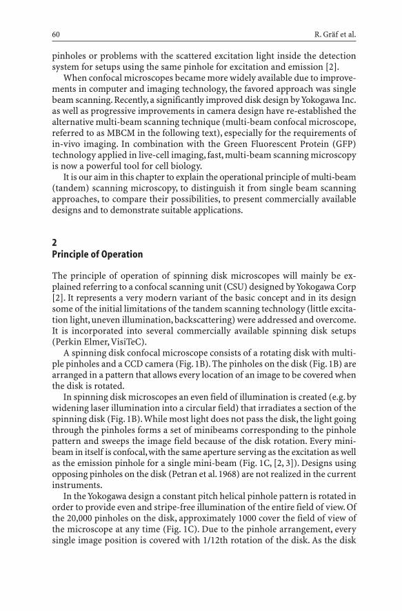
Fig. 1A–C Operating principles of single and multi-beam scanning confocal microscopes:A schematic drawing of a single beam scanning confocal microscope; B schematic drawingof a multi-beam scanning confocal microscope (Yokogawa CSU 10); C the constant pitch helical pinhole pattern of the Yokogawa spinning disk in the image field. During rotation ofthe disk, the pinholes evenly sweep the whole field of view
A B
C
beam scanning confocal approach was parallelized to utilize multiple beamsand corresponding pinholes [1]. Although this approach overcame the severespeed disadvantage of the single beam scanning method, it had significantproblems of its own. For fluorescence imaging, the technology suffered from little excitation light reaching the sample due to the limited pinhole area (ap-proximately 1%).Additional drawbacks were the requirement of high precisionin the pinhole placement for designs with opposing excitation and emission
pinholes or problems with the scattered excitation light inside the detectionsystem for setups using the same pinhole for excitation and emission [2].
When confocal microscopes became more widely available due to improve-ments in computer and imaging technology, the favored approach was singlebeam scanning. Recently, a significantly improved disk design by Yokogawa Inc.as well as progressive improvements in camera design have re-established thealternative multi-beam scanning technique (multi-beam confocal microscope,referred to as MBCM in the following text), especially for the requirements ofin-vivo imaging. In combination with the Green Fluorescent Protein (GFP)technology applied in live-cell imaging, fast, multi-beam scanning microscopyis now a powerful tool for cell biology.
It is our aim in this chapter to explain the operational principle of multi-beam(tandem) scanning microscopy, to distinguish it from single beam scanning approaches, to compare their possibilities, to present commercially available designs and to demonstrate suitable applications.
2Principle of Operation
The principle of operation of spinning disk microscopes will mainly be ex-plained referring to a confocal scanning unit (CSU) designed by Yokogawa Corp[2]. It represents a very modern variant of the basic concept and in its designsome of the initial limitations of the tandem scanning technology (little excita-tion light, uneven illumination, backscattering) were addressed and overcome.It is incorporated into several commercially available spinning disk setups(Perkin Elmer, VisiTeC).
A spinning disk confocal microscope consists of a rotating disk with multi-ple pinholes and a CCD camera (Fig. 1B). The pinholes on the disk (Fig. 1B) arearranged in a pattern that allows every location of an image to be covered whenthe disk is rotated.
In spinning disk microscopes an even field of illumination is created (e.g. bywidening laser illumination into a circular field) that irradiates a section of thespinning disk (Fig. 1B).While most light does not pass the disk, the light goingthrough the pinholes forms a set of minibeams corresponding to the pinholepattern and sweeps the image field because of the disk rotation. Every mini-beam in itself is confocal,with the same aperture serving as the excitation as wellas the emission pinhole for a single mini-beam (Fig. 1C, [2, 3]). Designs usingopposing pinholes on the disk (Petran et al. 1968) are not realized in the currentinstruments.
In the Yokogawa design a constant pitch helical pinhole pattern is rotated inorder to provide even and stripe-free illumination of the entire field of view. Ofthe 20,000 pinholes on the disk, approximately 1000 cover the field of view ofthe microscope at any time (Fig. 1C). Due to the pinhole arrangement, everysingle image position is covered with 1/12th rotation of the disk. As the disk
60 R. Gräf et al.

rotates with 1800 rpm (i.e. 30 rps) this amounts to 30¥12=360 full frames thatare acquired per second [2].
To avoid crosstalk between the spots of individual minibeams, the pinholesare spaced significantly apart [3]. Accordingly, only a small area of the disk iscovered by pinholes (1–4%) and most of the excitation light does not reach thesample because it is blocked by the disk. In the Yokogawa design this problemis overcome by a second disk in front of the pinhole disk (Fig. 1C). It containsmicrolenses arranged in the same pattern as the pinholes. These collect the excitation light and focus it into the pinholes thereby significantly increasingthe excitation light throughput from approx. 1% to 40–60% [2].
A confocal image is formed almost instantaneously and can be directlyviewed through the eyepiece of the scanhead.
In SBCMs, the emitted light is detected by photomultiplier tubes (PMTs) thatread out intensities over time. Spatial information is not perceived. The image isreconstituted by plotting the intensity value of a certain time-point to the corre-sponding x-y-position of the scanning beam. MBCMs use a two-dimensional detector (a CCD camera) to record the intensity and spatial position of all mini-beams simultaneously (Fig.1B).The frame rate is defined by the camera exposuretime and the frame readout speed of the camera. Maximally it can go up to 1/12of the rotation frequency of the spinning disk (i.e. 360 fps in case of the CSU-10).
The characteristic differences between SBCMs and MBCMs consist in (1) serial against a parallelized scanning approach and (2) the mode of detection(PMTs vs CCD camera). All further differences between SBCMs and MBCMs result from these two initial factors.
3Comparison of Single Beam and Multi-beam Scanning Confocal Imaging
The following section will discuss how the differences in the images taken onboth systems arise.
3.1Image Acquisition Rate
In a SBCM the image acquisition rate is limited by the speed of the scan mir-rors. The fastest scanning units currently available are operating at resonancefrequency, thereby achieving 512-line-frame rates close to video rate or morethan 100 Hz for reduced 32-line frame formats.
In a MBCM the image acquisition rate is limited by the speed of the camerareadout. In the CSU-10 version of the Yokogawa scanhead the rotation frequencyof the disc was limiting the acquisition rate to 360 Hz, which is no longer thecase for the CSU-21 that can rotate with higher speeds.
As soon as light intensity becomes the limiting factor which is clearly thecase for live specimen fluorescence imaging applications, images with similar
Live Cell Spinning Disk Microscopy 61

quality can be acquired much faster on a MBCM, due to its two- to fivefoldoverall higher efficiency (see below) and about 1000-fold higher integrationtime per pixel (pixel dwell time) allowing for higher light throughput per timeunit without saturation of the fluorophore (see below).
To increase the image acquisition rate while keeping the light flux throughthe sample constant there are the principal possibilities to either sacrifice spa-tial resolving power or reduce the observed volume. Using the zoom functionand changing the pinhole diameter the size of voxels and thereby resolvingpower of the system is easily and flexibly adjustable in the SBCM while in theMBCM the resolving power can only be changed stepwise by changing the objective, using an optovar or reading out the camera in binning mode (see also“Optical sectioning and confocality” below). In addition the SBCM can scanrather complexly shaped regions. Taken together, optimizing the observationvolume is easier on a SBCM. This advantage however does not make the SBCMthe superior tool for fast image acquisition except for applications where lineregions are to be observed as for example in scanning a single line along anaxon to measure the propagation of action potentials.
3.2Efficiency, Photobleaching and Phototoxicity
According to theoretical estimates the overall light loss on optical componentsalong the optical path of a filter based SBCM is expected to be similar to the loss inside the CSU10 based MBCMs (calculations according to [4], based onspecifications in [5]), thus, differences in efficiency mainly rely on the differentsensitivities of the detectors, which is in good agreement with our own findingsand those of others [2].
The quantum efficiency of current CCD cameras (up to 75%) is significantlyhigher than that of PMTs (maximum 25% in most commercially available systems). Moreover, with the latest development of ‘on chip amplifying’ CCDsthat achieve a strong amplification of the incoming signal while preserving agood spatial resolution, appropriate confocal acquisition of very fast biologicalprocesses inside living tissue has become feasible.While the higher efficiency inthe detection of photons will reduce photobleaching and phototoxicity by mak-ing better use of the emitted photons, another advantage of MBCMs over SBCMsfor live specimen imaging results from the higher efficiency in excitation of thefluorophores by the MBCM.
In single beam scanning, a high intensity laser beam passes over the sampleand illuminates every region intensely, but only for a very short period of time(typically 2–3 µs). Only the light put into the sample and read out from the sam-ple during this time is available to transport the information for the generationof the image. As a result, the excitation light has to be intense in order to exciteenough fluorophores during this short time. In multi-beam scanning, the excita-tion light is split into many mini-beams of correspondingly lower intensity. How-ever, several of these beams pass over the same region sequentially and the emis-
62 R. Gräf et al.

sion of all their passes is collected during the exposure time of the camera expo-sure. The illumination time per pixel is therefore significantly (1000-fold) longer.
We have analyzed the effects of these very different types of illumination by extending model calculations made by [6] for single beam scanning to amultiple beam situation(see Appendix at the end of the chapter).
We find that in the MBCMs significantly less excitation light is needed for thegeneration of an equivalent image due to two reasons: (1) the detection systemis more efficient (see above); (2) the fluorophore saturation level is low. InSBCMs excitation light levels are close to the saturation of the fluorophore, a situation where the number of photons emitted by a fluorophore no longer in-creases proportionally with increasing excitation light intensity is easily reached,while in MBCMs the excitation light level is typically far from saturation of thefluorophore. The reduction of excitation light will at the same time also avoidpotential photodamage by photochemical reactions independent of the fluo-rophore label (e.g. flavins) and in our opinion constitutes an additional impor-tant advantage for MBCM over SBCMs in the observation of living samples.
3.3Multichannel Imaging
For many biological applications, the imaging of more than one fluorescencechannel is required. This can be done on spinning disk systems by sequentiallyacquiring the different image channels onto the CCD and changing the exci-tation light and/or the emission filter between the channels. While switchingbetween different excitation light lasers employing acousto-optical tunable filters (AOTFs) is fast (2 ms), changing emission filters involves filter wheelsand is therefore ten times slower. Sequential multichannel acquisition involvesa reduction in the image acquisition rate which can become a severe limita-tion for colocalisation studies of moving structures. Fast moving structures inthe image might move between the acquisition of the channels and thus leadto mismatches between image channels.
Parallel acquisition is possible on MBCMs but requires modifications to thedetection system. In such modified setups, the emitted fluorescence is split intolonger and shorter wavelength components by a beamsplitter and either pro-jected onto separate CCD cameras or onto different regions of the same CCDchip (DualView Beamsplitter). The recent introduction of sensitive color CCDcameras (like the Hamamatsu 3CCD camera) also has further potential for fastmultichannel imaging (T. Nagai, personal communication) without significantalterations to the detection system.
Due to problems of significant crosstalk and cross-excitation between flu-orophores (see review by Zimmermann in this issue), multichannel imaging isvery often performed sequentially even on potentially parallel acquisition systems like SBCMs. By switching excitations line by line, SBCMs possess a sequential acquisition mode that avoids mismatches between channels, whichis not available for MBCMs. For most applications, however, the subsecond
Live Cell Spinning Disk Microscopy 63

frame rates for multichannel imaging achievable on spinning disk confocals areadequate.
3.4Regional Bleaching
Fluorescence Recovery after Photobleaching (FRAP) (for a review, see Houts-muller in this issue) and photoactivation [7] or photoconversion of fluorescentproteins (see Miyawaki et al. in this issue) are powerful techniques to investi-gate protein dynamics inside living cells. These techniques require a bleachingor activation step, i.e. a short irradiation of a defined image sub-region with intense laser light and is easily performed on SBCMs.Although some spinningdisk systems also use laser light for excitation, the laser cannot be used for spotor region bleaching in the existing setups. It is widened for the illumination ofthe whole field of view and cannot be specifically positioned within the image.Regional bleaching on spinning disk systems could however be performed withan additional positionable laser.This would require customization of the system,but it would be a formidable application considering the excellent fast time-lapse capacity of spinning disk systems.
3.5Optical Sectioning and Confocality
The thickness of an optical section in a SBCM microscope can be varied by adjusting the diameter of the detection pinhole, while the pinhole diameter andtherefore sectioning depth is fixed in MBCMs. The depth discrimination of thesystem is determined by the numerical aperture (NA) and magnification of theobjective lens. For the CSU-10 from Yokogawa Inc. pinhole diameter and spac-ing are calculated to match a 1.4 NA 100¥ lens for green excitation light andyield a 500 nm diameter projection of the pinhole in the object plane which isabout 1 Airy Unit (AU) for an excitation wavelength of 550 nm and an opticalsection of about 0.8 µm will be generated.
To achieve other section depths using the CSU-10, the investigator is limitedby the available objective lenses. Using a 1.4 NA 60¥ lens the projection of theinvariant pinhole into the object plane will be larger than 1 AU resulting in alarger z-depth of 1.25 µm. Using 1.3 NA 40¥ the section is about 1.8 µm. (Forthe Olympus DSU described below, discs with different optical properties areavailable to match the respective objective lenses and thereby higher flexibil-ity is generated). Contributions of out-of-focus fluorescence into neighboringpinholes is to be expected in multi-beam systems depending on the fluores-cence intensity and distribution inside the sample, thereby compromisingtheir confocality [2]. Theoretical depth discrimination capability is thereforebetter in single beam setups. It should however be kept in mind that in orderto achieve a high resolution excellent contrast is required which on a singlebeam confocal is usually difficult to achieve during live specimen imaging [8].
64 R. Gräf et al.

Under low signal to noise conditions the multi-beam confocal may achieve evenbetter resolution due to its higher detection efficiency (see above).
3.6Conclusion
Spinning disk microscopes are well suited for in vivo imaging and under certainconditions perform better than SBCMs for several reasons: (1) high frame ratescan be achieved; (2) the use of CCD detectors provides high detection efficien-cies; and (3) low intensity excitation light is used. Some of these advantages overSBCMs vanish if multichannel measurements are to be performed. Sequentialacquisition compromises the advantage of fast acquisition and generates prob-lems with respect to co-localisation studies while attempts to simultaneous acquisition using several cameras or beamsplitters are either tricky to align andexpensive or severely compromise the light budget if emission beamsplitters orcolor cameras are employed. None of the commercially available variants ofspinning disk microscopes are equipped for regional bleaching as required forphotobleaching and photoactivation measurements. The overall resolutionachieved of MBCMs is expected to be similar or better to that of SBCMs underlow S/N condition as in live cell imaging due to higher detection efficiency. Themain differences of the two system types are summarized in Table 1.
Live Cell Spinning Disk Microscopy 65
Table 1 Overview of single and multi beam confocal microscope features for in-vivo imag-ing applications
Microscope type Single beam confocal Multi beam confocal microscope microscope
Acquisition speed Limited frame rate High frame rate+ +++
Detection efficiency Photomultiplier tube CCD camera+ ++
Bleaching rates for Higher, more emission Lower, less emission equivalent images photons required photons required
+ ++
Multichannel imaging Simultaneous detection, Sequential detectionsequential detection++ +
Region specific Possible Not possible (w/o bleaching additional hardware)
++ –
Optical sectioning, Adjustable pinhole Fixed pinhole diameter,axial resolution diameter possible crosstalk between
neighboring pinholes++ +

4Available Designs for Video-Rate Confocal Microscopy
In this section a short overview over commercially available multi-beam scan-ning systems is given. In addition, other existing confocal designs that alsoprovide high frame rates are briefly mentioned.
4.1Multi-beam Designs
4.1.1Laser-Based Spinning Disk Confocals
Since it is a self-contained solution, Yokogawa confocal scanning units (CSU)with the double disk design are employed in several commercial solutions (e.g.Yokogawa, Perkin Elmer, VisiTec, Solamere). In addition to the CSU-10, themore recent CSU-21 with higher disk rotation speeds and switchable filters isalso available. The systems are operated with a variety of lasers and a CCD cam-era. For switching between fluorescence channels, solutions with filterwheelsas well as with AOTFs exist. For simultaneous two-channel imaging, setups withtwo cameras are also available.
4.1.2White Light Based Spinning Disk Confocals
Two commercially available designs use Xenon or Mercury arc lamps for excitation instead of laser light. Because of the broad emission spectrum of thelight source, the excitation light is controlled and easily varied by the use ofexcitation filters. This flexibility is not available with lasers as these are lim-ited to specific excitation lines. They can be easily added onto an existingwidefield system at relatively low cost and quick switches between widefieldand confocal imaging are possible with them. They do provide images withimproved z-resolution, but the optical sectioning capability is inferior to single beam scanning confocals due to restrictions in the light budget that arecompensated by a decrease in confocality (see above).
The CARV module (ATTO Bioscience) contains a Nipkow disk with pinholesand can be added to a variety of widefield microscopes. The Olympus DiskScanning Unit (DSU) can be fitted to Olympus microscopes and uses a rotat-ing disk with a pattern of slits instead of pinholes. Its optical sectioning per-formance can be altered by the insertion of disks with different slit widths.
4.1.3Two-Photon Multi-Beam Scanning
A very different concept of multi-beam scanning is realized in Multifocal Multiphoton laser scanning Microscopy (TriM Scope, LaVision BioTec). In this
66 R. Gräf et al.

design a beam multiplexer is used to create an array of scanning foci (array canbe single or rectangular/quadratic shape) that is used for parallel scanning athigh rates. Functionally it is very different in that it uses multiphoton excita-tion to create its scanning foci and does not involve pinholes on the detectionside. A similar multiphoton approach is provided by [9]. Time-multiplexedmultifocal multiphoton microscopy overcomes the general problem of multi-focal microscopy, crosstalk between single foci [10].
4.2Video-Rate Confocal Microscopes of Other Designs
In addition to multi beam scanning, other solutions for fast confocal imaginghave been introduced over the years. With the increasing flexibility and speedof single beam scanning confocals many of them however have become obso-lete and have gone out of manufacture. Slit scanning confocals [11] use a stripeof excitation light instead of a single point.As this stripe has to be moved acrossthe sample in only one direction, scanning time per frame is significantly re-duced so that images can be acquired at high frame rates with a CCD camera.The x-y resolution is however asymmetrical and the confocality is also com-promised. Some existing commercial solutions (Meridian InSight, BioRadViewScan DVC 250) are not manufactured anymore. Recently, Carl Zeiss AG hasintroduced the LSM 5 LIVE based on the slit scanning concept. Its distin-guishing feature is a CCD line detector that allows very fast readout. Because ofthis, much higher frame rates at high scanning resolutions can be achieved thanwould be possible with a conventional CCD camera.
Fast scanning confocal microscopes increase the frame speed to video-rateby accelerated scanning of a single point. For this, either a resonant scanner oran acousto-optical deflector (AOD) is required [12]. The widely used NoranOdyssey XL employs an AOD for the fast scanning. Due to the AOD properties,the emission light cannot be completely descanned and has to pass through aslit instead of a pinhole aperture, thereby affecting confocality. The model is not produced anymore, but VisiTech International has recently introduced theVTeye based on the same concept. As a third way, Leica incorporated the reso-nant scanner approach into its existing range of confocal microscopes to offera fast, fully confocal spectral setup (TCS SP2 AOBS RS). The limitation here isonly in the zoom-in properties, as zooming can only be done centred due to theresonant scanner properties. As the imaging properties are like for any singlebeam scanning confocal, the comparison to spinning disk designs is as de-scribed above, but with higher frame rates gained at the cost of less detectedphotons.
Live Cell Spinning Disk Microscopy 67

5Single and Multi-Beam Confocal Imaging in the Analysis of CentrosomeDynamics in Dictyostelium
The analysis of centrosome dynamics in Dictyostelium discoideum by four-di-mensional imaging is a good example for an imaging task where three-dimen-sional movements of motile, small, fluorescent particles such as centrosomeshave to be recorded over time.
The centrosome is a nucleus-associated organelle that serves as the mainmicrotubule-organizing center in animal, plant and fungal cells. Its functionsinclude mitotic spindle organization, cytokinesis, cell cycle progression, or-ganelle positioning and the directionality of cell migration [13].The centrosomeduplicates once per cell cycle and the two centrosomal entities are separatedduring mitotic spindle formation where they are forming the spindle poles. Thecontrol of centrosome number, i.e. one per nucleus, seems to be essential for dividing cells to maintain their euploid state, since centrosome amplificationleading to supernumerary centrosomes is a hallmark of tumor cells [14–16].Dictyostelium amoebae are a good model system for centrosome research [17].Thus, we have created a Dictyostelium mutant characterized by green fluores-cent supernumerary centrosomes and a weak cytokinesis defect [18, 19]. Thiswas achieved by overexpression of DdCP224, a member of the XMAP215-fam-ily of microtubule-associated proteins. The chromosomes in these mutantswere visualized by co-expression of GFP-tagged histone2B. These mutants wereused to investigate the dynamics of supernumerary and nucleus-associatedcentrosomes during mitosis [19]. The microscopic setup had to meet several requirements. The small size of Dictyostelium centrosomes (diameter of ap-proximately 0.5 µm) requires the good spatial resolution of a confocal micro-scope. Their motility demands good temporal resolution and rapid acquisitionof z-stacks over time, since the green-fluorescent centrosomes tend to move out of the confocal plane. Furthermore, Dictyostelium cells are very sensitive to phototoxic effects, especially during mitosis and if they are exposed to blue light required for GFP-excitation. Therefore, this was a suitable imagingproblem to analyze differences in performance of spinning disk confocal mi-croscopy (Perkin-Elmer-Wallac Ultraview) and single beam scanning confocalmicroscopy (Zeiss LSM510 META).
Since mitotic progression was inhibited by illumination with too high lightintensities, long before any bleaching effect of GFP was detectable, the preven-tion of phototoxic effects turned out to be the most important task, indepen-dent of the imaging system used. Therefore, low laser powers had to be usedwhich implied different consequences. In the case of spinning disk microscopy,relatively long exposure times of 500 ms and 2¥2 binning had to be used re-sulting in a relatively low frame rate of approximately 1.3 frames/s and reducedpixel resolution. In the case of single beam laser scanning microscopy, low fluorescence signal intensities at a given laser setting require either high PMTvoltages, which increases image noise, or a larger pinhole diameter, which de-
68 R. Gräf et al.

creases resolution. The frame rate depends on scanning options, such as thewindow size (in pixels), scan speed, bi- or unidirectional scanning, averagingof accumulated scans or the use of a line step (e.g. scanning of every second linewith interpolation of the missing ones). To reach a rate of 1.3 frames/s a rela-tively small window size of 512¥256 was chosen and the scan speed was set tothe maximum. A line-step factor of 2 compensated the time needed to averagetwo scans of each line, which was necessary to reduce noise.
It was not possible to compare the two confocal systems with the same laserpower settings since both systems employ different lasers and filter sets. There-fore, settings were chosen which allowed viewing of the cells for at least 30 minwithout indications for phototoxic effects.
Both types of scan-heads were mounted on an inverted microscope and,therefore, glass-bottom petri dishes were used to view the cells. After the cellshad settled on the glass surface (~5 min), the medium was replaced by phos-phate buffer and the cells were flattened by agar overlay [20]. This reduced thehigh mobility of centrosomes in the z-direction and the number of z-levels required to follow the centrosome. The time delay between each stack was 10 s.Under these conditions, the Dictyostelium mutants were viewed at 21 °C for upto 30 min.
The image series shown in Fig. 2 represent maximum intensity projectionsof image stacks acquired with each of the two confocal systems. Both se-quences show mitotic progression of a cell with GFP-labeled spindle polesand supernumerary centrosomes (arrowheads at time-point “0 s” in Fig. 2) aswell as GFP-labeled chromosomes. Figure 2A shows a mononucleated cellwith one supernumerary centrosome and Fig. 2B a bi-nucleated cell with twosupernumerary centrosomes. Imaging started in early (Fig. 2A) and late(Fig. 2B) metaphase, respectively, with a bipolar mitotic spindle and chro-mosomes arranged in a metaphase plate. The supernumerary centrosomesare not involved in spindle dynamics but duplicate in anaphase (time-point“320 s” in Fig. 2A and “180 s” in Fig. 2B). Both sequences illustrate essentiallythe same process, but the image sequence obtained by spinning disk mi-croscopy reveals more details regarding the discernibility of the chromo-somes and the duplication event of the supernumerary centrosomes, wherea tiny spindle is visible between the two daughter centrosomes (Fig. 2A, time-point “360 s”). By contrast, the images obtained by single beam laser scan-ning microscopy are noisier and less detailed (Fig. 3). The chromosomes, forinstance, mostly appear as one mass instead of individual entities. This is dueto the chosen compromise between speed, sensitivity and resolution. Im-provement of any of the factors would have to be done at the cost of another.For example, taking out the line step to improve the y-resolution would haveto be compensated by deactivating the line-averaging to maintain the sameframe rate, thus leading to even more noise in the image. However, the sci-entific question, if and when supernumerary centrosomes duplicate, is solvedequally well by both time-lapse sequences, although the spinning disk movieis of higher quality.
Live Cell Spinning Disk Microscopy 69

70 R. Gräf et al.
A
B

Live Cell Spinning Disk Microscopy 71
Fig. 2A, B Comparison of the duplication of supernumerary centrosomes as acquired on aspinning disk confocal microscope (Perkin-Elmer-Wallac Ultraview) and a single beam laserscanning confocal microscope (Zeiss LSM510 META): A spinning disk confocal (MBCM). Liveobservation of a mitotic DdCP224-GFP/GFP-histone2B cell with initially one supernumerarycentrosome (arrowhead in the first image). Image acquisition started in late metaphase afterduplication of the nucleus-associated centrosome whose daughter centrosomes are locatedat the spindle poles. The time is indicated in seconds. Each image represents a maximum intensity z-projection of five confocal slices. Settings: z-distance, 0.5 µm each; exposure time,500 ms; frame rate, 1.3 fr/s; binning, 2¥2; B single beam confocal (SBCM). Live observationof a mitotic DdCP224-GFP/GFP-histone2B cell (cell edges are outlined in the first image) withinitially two supernumerary centrosomes (arrowheads in the first image). Image acquisitionstarted in late metaphase.The time is indicated in seconds.Each image represents a maximumintensity z-projection of five confocal slices. Settings: z-distance, 1 µm each; 512¥256 pixels;line-step, 2; averaging, twofold; pinhole size, 2.8 airy disk units; scan direction, unidirectional;scan speed, maximum; frame rate, 1.3 fr/s; scale bars 2 µm
Fig. 3A, B Comparison of signal to noise ratio between laser scanning confocal microscopyand spinning disk confocal microscopy. Single slices derived from the image sequences ofFig. 2 are shown in A and B. The respective plots of fluorescence intensity (displayed as graylevels of an 8-bit gray scale) along a straight line through the center of supernumerary centrosomes (A¢, B¢) reveal superior signal to noise ratio of spinning disc microscopy vs single beam scanning microscopy

In cases of stronger signals, the frame rate (by shorter exposures) or the res-olution (by reduction of binning) can be improved accordingly for spinningdisk microscopes.At the single beam scanning microscope the frame rate usedabove is already close to the limit for such imaging tasks since the scan speedwas set already close to the maximum. It can only be further improved by bidi-rectional scanning or omission of frame or line averaging. However, all thesesteps will reduce image quality.All improvements of the image quality, such asslower scanning, averaging of more scans or relinquishment of the line-stepfactor will significantly reduce the frame rate.
References
1. Petran M, Hadravsky M, Egger MD, Galambos R (1968) J Opt Soc Am 58:6612. Inoue S, Inoue T (2002) Methods Cell Biol 70:873. Kino GS (1995) In: Pawley JB (ed) Handbook of biological confocal microscopy. Plenum
Press, New York, p 1554. Stelzer EHK (1995) In: Pawley JB (ed) Handbook of biological confocal microscopy.
Plenum Press, New York, p 1395. Kawamura S, Negishi H, Ostuki S, Tomosada N (2002) Yokogawa Tech Rep Engl Ed 33:176. Tsien RY, Waggoner A (1995) In: Pawley JB (ed) Handbook of biological confocal
microscopy. Plenum Press, New York, p 2677. Patterson GH, Lippincott-Schwartz J (2002) Science 297:18738. Stelzer EHK (1998) J Microsc 189:159. Bewersdorf J, Pick R, Hell SW (1998) Opt Lett 23:655
10. Egner A, Andresen V, Hell SW (2002) J Microsc 206:2411. Amos WB,White JG (1995) In: Pawley JB (ed) Handbook of biological confocal micros-
copy. Plenum Press, New York, p 40312. Tsien RY, Bacskai BJ (1995) In: Pawley JB (ed) Handbook of biological confocal micros-
copy. Plenum Press, New York, p 45913. Rieder CL, Faruki S, Khodjakov A (2001) Trends Cell Biol 11:41314. Fisk HA, Mattison CP, Winey M (2002) Curr Opin Cell Biol 14:70015. Nigg EA (2002) Nat Rev Cancer 2:81516. Doxsey S (2002) Mol Cell 10:43917. Gräf R, Brusis N, Daunderer C, Euteneuer U, Hestermann A, Schliwa M, Ueda M (2000)
Curr Topics Dev Biol 49:16118. Gräf R, Daunderer C, Schliwa M (2000) J Cell Sci 113:174719. Gräf R, Euteneuer U, Ho TH, Rehberg M (2003) Mol Biol Cell 14:406720. Fukui Y,Yumura S,Yumura TK (1987) In: Spudich JA (ed) Methods in cell biology, vol 28.
Academic Press, Orlando, FL, p 34721. Dittrich PS, Schwille P (2001) Appl Phys B 73:829
72 R. Gräf et al.

Appendix
For comparing single and multi-beam scanning we follow a model calculationmade by [6] for single beam scanning of fluorescein at 1 mW intensity at 488 nmand extend it for multi-beam scanning.
The following values are being used:
– Laser power at 488 nm: 1 mW– Objective NA: 1.25– Peak excitation intensity in a Gaussian spot I=1.25¥1024 photons/cm2s– Fluorescein optical cross section cs=3.06¥10–16 cm2/molecule– Fluorescein lifetime rate constant kf=2.2¥108 s–1
– Fluorescein quantum efficiency Qe=0.9– Fluorescein bleaching efficiency Qb=3¥10–5
The photon emission rate of a fluorophore is determined by the intensity dependent excitation rate, the lifetime of the fluorophore and its quantum efficiency. The excitation rate and the fluorophore lifetime allow the calculationof the saturation of the fluorophore. The photon emission rate as well as bleach-ing rate is directly proportional to it.
Excitation rate constant ka = cs ¥ 1 (1)
kaSaturation S = 92 (2)ka + kf
Emission rate kem = Qekf S (3)
Bleaching rate kem = Qbkf S (4)
Total Sample Irradiation Per Frame
How much light goes into a sample for a single exposure in the two setups? For this, an identical laser source and identical frame rates are assumed for bothsystems. In single beam scanning, the beam moves with finite speed over all regions of the sample. The total irradiation R of the sample is thus the productof the intensity of the laser beam I and the total acquisition time t for a frame.
R = I ¥ t (5)
The comparison to a multi-beam system is actually quite simple: With an iden-tical laser, the same intensity I is emitted for the same acquisition time t. Thedifference in photons actually hitting the sample is just determined by thetransmission efficiency E of the spinning disk.
R = I ¥ t ¥ E (6)
For identical frame rates and laser powers, the difference of total irradiation between a single beam confocal and a Yokogawa scan head would thus be a factor of approx. 2 (efficiency E 0.4–0.6).
Live Cell Spinning Disk Microscopy 73

Fluorescence emission
With this difference of total irradiation how much fluorescence is actually collected? This involves two aspects, the amount of emission photons and theefficiency of detection. In single beam scanning at 1 mW excitation intensity,fluorescein molecules in the region of peak intensity are 63% saturated, i.e. only37% are not excited at any given time according to 1 and 2. The fluorescenceemission rate kem amounts to 1.26¥108 photons/s according to 3.
In multi-beam scanning with a Yokogawa disk, the intensity of a single mini-beam is significantly reduced and can be calculated as
IImulti_beam = 93 ¥ E (7)
npinholes
For n=1000 pinholes and a transmission efficiency E=0.5, the intensity of aminibeam would amount to 1/2000th of the single beam intensity.
The saturation level of fluorescein in such a mini-beam is 0.09% accordingto 1, 2 and 7. The fluorescence emission rate is 1.72¥105 photons/s accordingto 3.
Whereas the difference in excitation intensity between single and multi-beam scanning is 1:2000, the difference in emission is only 1:731. This meanssignificantly higher excitation efficiency at low intensities. This is an effect ofthe decreasing numbers of fluorophores available in the unexcited state at highsaturation levels.
Fluorescence Emission Per Frame
With the fluorescence emission rates kem of single and multi-beam scanning setups known, how many photons are actually emitted by a fluorophore in asingle frame?
For single beam scanning, the amount of emitted photons per fluorophoreper frame Nem is
Nem = kem ¥ t (8)
where t is the pixel dwell time of the beam. Using the calculation example anda pixel dwell time of 2.5 µsec this amounts to 300 photons emitted by a singlefluorophore per frame.
For a spinning disk, the calculation can not be performed with pixel dwelltimes and the number of beam passes, since these parameters (radial velocity,number of passing pinholes) vary over the image field according to the radialposition along the disk. The product of beam dwell times and beam passes ishowever a constant over the whole field (even illumination).
To derive a value equivalent to the single beam pixel dwell time for a spin-ning disk microscope, the total irradiation of the image field per frame has tobe divided by the number of image pixels to get a representative illumination
74 R. Gräf et al.

value for each pixel under even illumination. The division of this value by theintensity of a mini-beam provides the total time of illumination centered on apixel and thus an equivalent to the single beam pixel dwell time.
Accordingly, for multi-beam scanning the amount of emitted photons perfluorophore per frame Nem is
RNem = kem ¥ 994 (9)
n ¥ Imulti_beam
where R is the total illumination of the sample per frame according to 6 and nis the number of image pixels.
Using this calculation, approximately 420 photons are emitted by a fluo-rophore under multi-beam conditions per frame.
This is an idealized calculation assuming identical areas of illumination forthe single and multi-beam setups. In reality, only 63% of the circularly widenedexcitation beam goes into the rectangular (1.3:1.0) detection area of the CCD,so that less excitation light is actually used in the multi-beam system than for the calculation. Taking this into account, approximately equal amounts offluorescence photons can be expected for single and multi-beam systems.
Bleaching Rates
The photobleaching of fluorophores by illumination is still a poorly understoodprocess [6]. Assuming linear bleaching kinetics even at the high intensities present in single beam scanning, as indicated by fluorescence correlation spec-troscopy data [21], equal amounts of photons emitted per frame mean that thebleaching rate is more or less equal in multi-beam scanning and in single beamscanning microscopy.
Live Cell Spinning Disk Microscopy 75