Safety Rules - Human Power Submarine - International Submarine Race

Design Report Littoral Warfare Submarine (SSLW)
VT Total Ship Systems Engineering
Virginia Tech Ocean Engineering AOE 4065/4066
Fall 2004 – Spring 2005 Team SCRAP
Justin Chin ___________________________________________
Davy Hansch ___________________________________________ 19058
Nate Lambeth ___________________________________________ 19605
Chris Michie ___________________________________________ 18931
Dave Owens ___________________________________________ 19***
Solomon Whalen ___________________________________________ *****

SSLW Design – VT Team 4 Page 2
Executive Summary This report describes the Concept Exploration and
Development of a Littoral Warfare Submarine (SSLW) for the United States Navy. This concept design was completed in a two-semester ship design course at Virginia Tech.
The SSLW requirement is based on the need for a small, maneuverable vehicle to support special warfare operations. A shallow water submarine allows the possibility of covert insertion and extraction of these forces, as well as reconnaissance to support their operations and other theater operations. An Acquisition Decision Memorandum was produced specifying small size, high maneuverability, a non-nuclear air-independent propulsion system, and the need to operate from a mother ship or sea-base concept.
Concept Exploration trade-off studies and design space exploration are accomplished using a Multi-Objective Genetic Optimization (MOGO) after significant technology research and definition. Objective attributes for this optimization are cost, risk (technology, cost, schedule and performance) and military effectiveness. The product of this optimization is a series of cost-risk-effectiveness frontiers which are used to select alternative designs and define Operational Requirements (ORD1) based on the customer’s preference for cost, risk and effectiveness.
SSLW Design 38, presented here, achieves a high level of effectiveness while maintaining a medium level of risk by using a cutting-edge propulsion system with extremely reliable and low-risk lead-acid batteries. The fuel cell propulsion system along with a reformer allows for extremely quiet operation completely independent of an external air source. The catamaran design gives a large deck area and features a small molded depth well-suited for littoral waters. The boat’s covert features allow it to slip in and out of enemy waters undetected, yet it retains the ability to strike enemy naval targets if the need arises.
Concept Development included hull form development, structural finite element analysis, propulsion and power system development and arrangement, general arrangements, machinery arrangements, combat system definition and arrangement, cost and producibility analysis and risk analysis. The final concept design satisfies critical operational requirements in the ORD within cost and risk constraints with additional work required to ensure a good
balance between weight and volume, evaluate static and dynamic stability and seakeeping, and finalize overall structural design.
Ship Characteristic Value LOA 147 ft Beam 28 ft Depth 13 ft Submerged Displacement 1430 lton Sustained Speed 20 knots Endurance Speed 6 knots Sprint Range 40 n m Endurance Range 2590 nm Diving Depth 290 ft
Propulsion and Power 250kW PEM Fuel Cell w/
reformer, lead-acid batteries, 2 AC motors, and IPS system
BHP 250 kW
Personnel 9 enlisted, 3 officer, 8 special
forces/mission technician OMOE (Effectiveness) 0.716 OMOR (Risk) 0.444 Ship Acquisition Cost $369M Combat Systems (Modular and Core)
4x inboard torpedo tubes, 6x external encapsulated torpedoes, 4x countermeasure launchers, passive, active, and mine avoidance sonar, four man lockout trunk, 2x Zodiac
RHIB, accommodations for 1 special warfare unit, degaussing system, and 1 8x8x20ft. Payload
Interface Module (PIM)

ASC Design – VT Team 2 Page 3
Table of Contents
EXECUTIVE SUMMARY................................................................................................................................................................................ 2
TABLE OF CONTENTS .................................................................................................................................................................................. 3
1 INTRODUCTION, DESIGN PROCESS AND PLAN.............................................................................................................................. 5 1.1 INTRODUCTION.............................................................................................................................................................. 5 1.2 DESIGN PHILOSOPHY, PROCESS, AND PLAN ............................................................................................................. 5 1.3 WORK BREAKDOWN..................................................................................................................................................... 7 1.4 RESOURCES.................................................................................................................................................................... 7
2 MISSION DEFINITION........................................................................................................................................................................ 8 2.1 CONCEPT OF OPERATIONS........................................................................................................................................... 8 2.2 PROJECTED OPERATIONAL ENVIRONMENT (POE) AND THREAT .......................................................................... 8 2.3 SPECIFIC OPERATIONS AND MISSIONS....................................................................................................................... 8 2.4 MISSION SCENARIOS .................................................................................................................................................... 8 2.5 REQUIRED OPERATIONAL CAPABILITIES................................................................................................................... 9
3 CONCEPT EXPLORATION............................................................................................................................................................... 10 3.1 STANDARDS AND SPECIFICATIONS........................................................................................................................... 10 3.2 TRADE-OFF STUDIES, TECHNOLOGIES, CONCEPTS AND DESIGN VARIABLES................................................... 10
3.2.1 Hull Form Alternatives.............................................................................................................................................10 3.2.2 Sustainability Alternatives........................................................................................................................................11 3.2.3 Propulsion and Electrical Machinery Alternatives..............................................................................................11 3.2.4 Automation and Manning Parameters...................................................................................................................17 3.2.5 Combat System Alternatives.....................................................................................................................................17
3.3 DESIGN SPACE............................................................................................................................................................. 22 3.4 SHIP SYNTHESIS MODEL............................................................................................................................................ 22
3.4.1 Input Module...............................................................................................................................................................23 3.4.2 Combat System Module............................................................................................................................................23 3.4.3 Propulsion Module....................................................................................................................................................23 3.4.4 Hull Form Module.....................................................................................................................................................23 3.4.5 Electric Module..........................................................................................................................................................24 3.4.6 Resistance Module.....................................................................................................................................................24 3.4.7 Weight and Stability Module....................................................................................................................................24 3.4.8 Tankage Module.........................................................................................................................................................24 3.4.9 Space Required Module............................................................................................................................................24 3.4.10 Feasibility Module.....................................................................................................................................................24
3.5 MULTI-OBJECTIVE OPTIMIZATION........................................................................................................................... 25 3.5.1 Overall Measure of Effectiveness (OMOE)...........................................................................................................25 3.5.2 Overall Measure of Risk (OMOR) ..........................................................................................................................28 3.5.3 Cost...............................................................................................................................................................................31
3.6 OPTIMIZATION RESULTS............................................................................................................................................ 31 3.7 DESIGN 38 BASELINE CONCEPT DESIGN ................................................................................................................. 32
4 CONCEPT DEVELOPMENT (FEASIBILITY STUDY)....................................................................................................................... 35 4.1 GENERAL ARRANGEMENT AND COMBAT OPERATIONS CONCEPT (CARTOON)................................................. 35
4.1.1 Mission Operations...................................................................................................................................................36 4.1.2 Machinery Room Arrangements..............................................................................................................................37
4.2 HULL FORM ................................................................................................................................................................. 37 4.3 STRUCTURAL DESIGN AND ANALYSIS..................................................................................................................... 38
4.3.1 Geometry, Components and Materials ..................................................................................................................38 4.3.2 Loads............................................................................................................................................................................39 4.3.3 Adequacy.....................................................................................................................................................................40
4.4 POWER AND PROPULSION.......................................................................................................................................... 40 4.4.1 Resistance....................................................................................................................................................................40

ASC Design – VT Team 2 Page 4
4.4.2 Propulsion...................................................................................................................................................................41 4.4.3 Electric Load Analysis (ELA) ..................................................................................................................................42 4.4.4 Fuel Calculation........................................................................................................................................................42
4.5 MECHANICAL AND ELECTRICAL SYSTEMS............................................................................................................. 43 4.5.1 Integrated Power System (IPS) ...............................................................................................................................43 4.5.2 Service and Auxiliary Systems.................................................................................................................................44 4.5.3 Ship Service Electrical Distribution.......................................................................................................................44
4.6 MANNING..................................................................................................................................................................... 44 4.7 SPACE AND ARRANGEMENTS.................................................................................................................................... 44
4.7.1 Volume .........................................................................................................................................................................45 4.7.2 Internal Arrangements..............................................................................................................................................45 4.7.3 Machinery Room Arrangements..............................................................................................................................46 4.7.4 Living Arrangements.................................................................................................................................................47 4.7.5 External Arrangements.............................................................................................................................................48
4.8 WEIGHTS AND LOADING............................................................................................................................................ 48 4.8.1 Weights ........................................................................................................................................................................48 4.8.2 Loading Conditions...................................................................................................................................................49
4.9 HYDROSTATICS AND STABILITY............................................................................................................................... 49 4.9.1 Intact Stability ............................................................................................................................................................49 4.9.2 Damaged Stability .....................................................................................................................................................50
4.10 SEAKEEPING, MANEUVERING, AND CONTROL ....................................................................................................... 50 4.11 COST AND RISK ANALYSIS........................................................................................................................................ 50
4.11.1 Cost and Producibility..............................................................................................................................................50 4.11.2 Risk Analysis...............................................................................................................................................................51
5 CONCLUSIONS AND FUTURE WORK............................................................................................................................................. 51 5.1 ASSESSMENT................................................................................................................................................................ 51 5.2 FUTURE WORK............................................................................................................................................................ 51 5.3 CONCLUSIONS.............................................................................................................................................................. 52
APPENDIX A – SSLW MISSION NEED STATEMENT (MNS)...................................................................................................................... 54
APPENDIX B – SSLW ACQUISITION DECISION MEMORANDUM (ADM) ............................................................................................... 56
APPENDIX C– OPERATIONAL REQUIREMENTS DOCUMENT............................................................................................................... 57
APPENDIX D – MACHINERY EQUIPMENT LIST....................................................................................................................................... 60
APPENDIX E - WEIGHTS AND CENTERS................................................................................................................................................... 61
APPENDIX F – SSCS SPACE SUMMARY..................................................................................................................................................... 62
APPENDIX G - MATHCAD MODEL............................................................................................................................................................. 63

ASC Design – VT Team 2 Page 5
1 Introduction, Design Process and Plan
1.1 Introduction
This report describes the concept exploration and development of a Littoral Warfare Submarine (SSLW) for the United States Navy. The SSLW requirement is based on the SSLW Mission Need Statement (MNS), and Virginia Tech SSLW Acquisition Decis ion Memorandum (ADM), Appendix A and Appendix B. This concept design was completed in a two-semester ship design course at Virginia Tech. SSLW must perform the following missions:
- Covert insertion, extraction, and support of U.S. Special Forces
- Covert intelligence gathering (electronic, human, and visual)
- Covert, precision mine countermeasures and mine warfare
- Support autonomous and remotely operated land, air, and sea vehicles (multiple, flexible mission packages)
The SSLW design is driven by several key constraints:
- Extended endurance
- Low cost
- Low manning
- Highly producible, minimum time for concept-to-delivery
- Platforms must operate within current logistics support capabilities
- Non-nuclear or innovative small nuclear
SSLW will be able to operate independently for extended time periods while performing multiple mission tasks. It will be capable of deploying U.S. Special Forces deep within coastal waters and performing ISR and Mine/Anti-Mine operations. It must depend on passive stealth to slip away through enemy restricted waters without detection.
SSLW will operate from a mother ship, and deploy into restrictive littoral regions. It will utilize passive stealth qualities, relatively small size, and high maneuverability to routinely operate closer to enemy shores than previous US submarines. This will allow SSLW to deploy Special Forces closer to shore, limit their exposure to cold water, provide an offshore base and avoid possible detection. The SSLW will also perform harbor penetration missions to gain detailed ISR and perform MCM. UUVs will extend the SSLW mission capabilities to obtain more detailed ISR and perform limited mine hunting operations.
SSLW will have a minimum endurance range of 1000 nm at 10 knots, a minimum sustained (sprint) speed of 15 knots, a minimum sprint range of 25 nm, a minimum operating depth of 250 feet, and a service life of 30 years. It shall be completely air-independent. It is expected that 10 ships of this type will be built with IOC in 2015. Average follow-ship acquisition cost shall not exceed $500M. Manning shall not exceed 35 personnel.
1.2 Design Philosophy, Process, and Plan
The traditional approach to ship design is largely an ‘ad hoc’ process. Experience, design lanes, rules of thumb, preference, and imagination guide selection of design concepts for assessment. Often, objective attributes are not adequately synthesized or presented to support efficient and effective decisions. This project uses a total system approach for the design process, including a structured search of the design space based on the multi-objective consideration of effectiveness, cost and risk.
The scope of this project includes the first two phases in the ship design process, Concept Exploration and Concept Development, as illustrated in Figure 1. Also in Figure 1, note how the Concept Exploration and Development stages follow the US Navy acquisition process. The concept exploration process is shown in Figure 2. The process begins with the identification of a mission need and general requirements. Other steps in the process include developing models for ship synthesis, risk, effectiveness, and cost to quantitatively balance and compare different designs. This comparison is carried out using variable screening and optimization. An acquisition decision selects preferred alternatives from these designs. The products of this process are a preliminary Operational Requirements Document (ORD1) that specifies performance and cost requirements, a baseline concept design, and a selection of preferred technologies.

ASC Design – VT Team 2 Page 6
In Concept Exploration (Figure 2), a multiple-objective design optimization is used to search the design space and perform trade-offs. SSLW Concept Exploration considers various combinations of hull form, propulsion systems, comb at systems and automation within the design space using mission effectiveness, risk and acquisition cost as objective attributes. A ship synthesis model is used to balance these parameters in total ship designs, to assess feasibility and to calculate cost, risk and effectiveness. The final design combinations are ranked by cost, risk and effectiveness, and presented as a series of non-dominated frontiers. A non-dominated frontier (NDF) represents ship designs in the design space that have the highest effectiveness for a given cost and risk. Concepts for further study and development are chosen from this frontier.
Figure 3 shows the more traditional design spiral process followed in Concept Development for this project. A complete circuit around the design s piral at this stage is frequently called a Feasibility Study. It investigates each step in the traditional design spiral at a level of detail necessary to demonstrate that assumptions and results obtained in concept exploration are not only balanced, but feasible. In the process, a second layer of detail is added to the design and risk is reduced. Notice that each step is not independently performed, but rather involves a large amount of collaboration among the other steps in order to evaluate effects of the design steps on other design aspects.
ConceptExploration
ConceptDevelopment
PreliminaryDesign
ContractDesign
DetailDesign
ExploratoryDesign
Mission orMarketAnalysis
Concept andRequirements
Exploration
TechnologyDevelopment
ConceptDevelopment
and FeasibilityStudies
ConceptBaseline
FinalConcept
Figure 1 – Ship Design Process
MNSMission Need
ADM / AOAGeneral
Requirement
Define Design Space
ModelingDOE - Variable
Screening & Exploration
RSM
Data
Expert Opinion
Physics-BasedModel
Effectiveness Model
Cost Model
Optimize - Generate
NDFs
Alternative or New
Technology
Ship Aquisition Decision
Alternative Requirement
Definition
ORD1Ship MS1
Technology Acquisition & Development
Ship System Design &
Development
Production Strategy
Ship Aquisition Decision
ORD1Ship MS1
Technology Acquisition & Development
Ship System Design &
Development
Production Strategy
Feasibility & Sensitivity Analysis
Variable Probability
Risk Model
Technology
Figure 2 – Concept Exploration Process

ASC Design – VT Team 2 Page 7
Requirement
Seakeeping
General Arrangements
Weights and Stability
Manning and Automation
Hull Geometry
Resistance and Power
Structures
Mechanical and Electrical
Cost and Effectiveness
Subdiv, Area and Volume
Machinery Arrangements
Figure 3
1.3 Work Breakdown
SSLW Team SCRAP consists of six students from Virginia Tech. Each student is assigned areas of work according to his or her interests and special skills as listed in Table 1. Most team members worked on many areas of the design, and very few design aspects were achieved by one student alone.
Table 1 - Work Breakdown Name Specialization
Justin Chin Machinery Arrangements, Electrical System Davy Hansch Structures, Weights Nate Lambeth Writer, Stability, Maneuvering and Control,
Seakeeping, OMOE/OMOR Chris Michie Resistance and Propulsion, Powering Dave Owens Hullform, General Arrangements, Balance Solomon Whalen Modeling, General Arrangements, Machinery
Arrangements
1.4 Resources
Computational and modeling tools used in this project are listed in Table 2.
Table 2 - Tools Analysis Software Package
Arrangement Drawings AutoCAD/Rhino Hull form Development AutoCAD/Rhino Hydrostatics Rhino Resistance/Power MathCAD Ship Motions GEORGE Ship Synthesis Model MathCad/Model Center Structure Model MAESTRO

ASC Design – VT Team 2 Page 8
2 Mission Definition
The SSLW requirement is based on the SSLW Mission Need Statement (MNS), and Virginia Tech SSLW Acquisition Decision Memorandum (ADM), Appendix A and Appendix B with elaboration and clarification obtained by discussion and correspondence with the customer, and reference to pertinent documents and web sites referenced in the following sections.
2.1 Concept of Operations
SSLW will operate from either a mother submarine or surface ship, requiring complete support until the time of launch for the mission. The platform will be forward deployed and able to operate independently for extended periods of time using multiple, flexible mission packages, autonomous systems and minimal crew. It will be capable of operating as a first strike platform, entering restricted waters and littoral areas undetected, carrying U.S. Special Forces with minimal exposure and deploying them deep within coastal waters. SSLW can serve as an off-shore base for the duration of the mission, performing ISR operations and gathering information in the interim. It must depend on passive stealth to slip away through enemy restricted waters without detection.
2.2 Projected Operational Environment (POE) and Threat
SSLW will operate in shallow coastal waters and must face all accompanying threats. A hostile littoral environment would present threats ranging from enemy diesel-electric submarines to surface ships or air assets with sonar, sonar buoys, and torpedoes to mines. The sub must be stealthy and flexible enough to identify and evade any threat that presents itself.
2.3 Specific Operations and Missions
SSLW mission components will include airborne littoral data collection, submerged littoral ISRT data collection, collecting intelligence on vessel movements, delivery and support of Special Forces, forward destruction/disruption of enemy subs and small boats, and mine reconnaissance, clearing, and laying. The platform must be flexible in order to perform any number of mission components or variations on them.
2.4 Mission Scenarios
Mission scenarios for the primary SSLW missions are provided in Table 3.
Table 3 - Sample Mission Day Mission scenario
1-3 Transit with host ship to forward deployment area 4-5 Configure mission packages, embark Special Forces 6 Transit to combat deployment area, deploy Special Forces
7-17 Conduct ISR and MCM operations, provide logistic and intelligence support to other units 18 Embark Special Forces, transit to re-supply area 19-21 Reconfigure mission packages, re-supply, disembark Special Forces 22 Transit to mission area 23-33 Conduct mine-laying and ECCM operations, provide intelligence support to other units
34 Transit to re-supply area 35-36 Reconfigure mission packages, embark mission specialist(s) 37-45 Conduct search and rescue and salvage operations 46-47 Rendezvous with salvage ship, deliver recovered payload 48 Transit to re-supply area

ASC Design – VT Team 2 Page 9
2.5 Required Operational Capabilities
In order to support the missions and mission scenarios described in Section 2.4, the capabilities listed in Error! Reference source not found. are required. Each of these can be related to functional capabilities required in the ship design, and, if within the scope of the Concept Exploration design space, the ship’s ability to perform these functional capabilities is measured by explicit Measures of Performance (MOPs).
Table 4 - Required Operational Capabilities ROC Description
ASW 1 Engage submarines (defensively)
ASW 1.3 Engage submarines at close range
ASW 7.6 Engage submarines with torpedoes
ASW 7.8 Engage submarines with missiles
ASW 10 Disengage, evade, and avoid submarine attack by employing countermeasures and evasion techniques
ASU 1 Engage surface threats with missiles or torpedoes
ASU 4.2 Detect and track a surface target with SONAR
ASU 6 Disengage, evade, and avoid surface attack
MIW 1 Conduct mine hunting
MIW 2 Conduct mine sweeping
MIW 3 Conduct magnetic silencing (degaussing, deperming, etc.)
MIW 4 Conduct mine laying
MIW 6.7 Maintain magnetic signature limits
CCC 3 Provide own unit CCC
CCC 4 Maintain data link capability
SEW 2 Conduct sensor and ECM operations
SEW 3 Conduct sensor and ECCM operations
FSO 5 Conduct search/salvage & rescue operations
FSO 6 Conduct SAR operations
FSO 7 Provide explosive ordnance disposal services
INT 1 Support/conduct intelligence collection
INT 2 Provide intelligence
INT 3 Conduct surveillance and reconnaissance
MOB 1 Steam to design capacity in most fuel efficient manner
MOB 3 Prevent damage (not control)
MOB 7 Perform seamanship and navigation tasks
MOB 10 Replenish at sea
MOB 12 Maintain health and well being of crew
MOB 14 Operate in towed or piggy-backed configuration
NCO 3 Provide upkeep and maintenance of own unit
LOG 1 Conduct underway replenishment (not vertical)
LOG 2 Transfer/receive cargo and personnel

ASC Design – VT Team 2 Page 10
3 Concept Exploration Chapter 3 describes SSLW Concept Exploration. Trade-off studies, design space exploration and optimization are
accomplished using a Multi-Objective Genetic Optimization (MOGO).
3.1 Standards and Specifications
Submarine standards and specifications are almost exclusively proprietary or classified information, and as such are not available to the team.
3.2 Trade-Off Studies, Technologies, Concepts and Design Variables
Available technologies and concepts necessary to provide required functional capabilities are identified and defined in terms of performance, cost, risk and ship impact (weight, area, volume, power). Trade-off studies are performed using technology and concept design parameters to select trade-off options in a multi-objective genetic optimization (MOGO) for the total ship design. Technology and concept trade spaces and parameters are described in the following sections.
3.2.1 Hull Form Alternatives
Selection of the Littoral Warfare submarine’s hull form must consider its unique operating environment. To effectively carry out its missions with covertness and stealth in shallow water, the hull form must be different from previous designs. The unique littoral environment necessitates a small, maneuverable submarine that can operate proficiently in less then 100 feet of water. The SSLW hull form must satisfy the following general requirements:
§ Decreased draft
§ Shallow water seakeeping
§ Stealth
§ Maneuverability
§ Structural Efficiency
§ Efficient use of inboard volume
An idealized, simplified hull form, shown in Error! Reference source not found., was used in concept exploration. The diameter of the forebody hemisphere, length of parallel midbody, length of afterbody, overall beam and overall depth are varied in the designs. This allows the optimization program to reduce the beam until a traditional cylindrical hull exists, while providing the option to consider an alternative hull form that has a more desirable beam to depth ratio for a littoral hull. Single and multiple decks are also considered in the design; however a large emphasis is placed on maintaining a small depth.
Figure 4 - Idealized Hullform
The structural concept for the SSLW pressure hull is a catamaran configuration with two separate pressure hulls connected by a third cylindrical section to create the small draft to beam ratio that is desired for the littorals. Error! Reference source not found. illustrates the cross section of this hull concept. The advantages / disadvantages of this catamaran hull are listed in Error! Reference source not found. . The most noteworthy quality of this design is that structural efficiency is maintained by allowing hoop stress to carry the primary pressure load. This reduces sheer stress and allows an elliptical external hull or envelope to be created without the added cost of additional steel.

ASC Design – VT Team 2 Page 11
Figure 5 - Cross Section of Catamaran Hull Design
Table 5 - Hullform Advantages and Disadvantages
Surface Stability
Dynamic Stability Maneuvering
Good Large-Object Spaces
Efficient use of steel structure
Structural Integrity
Resistance at Sustained Speed Cost
Elliptical Pressure Hull - + + - + + + + -
Catamaran – Style Pressure Hull + + - - - + + + + + - -
3.2.2 Sustainability Alternatives
SSLW minimum sustainability requirements are specified in Appendix B – SSLW Acquisition Decision Memorandum (ADM). Goals and thresholds were developed considering the mission, the location of the objective, and the distance between the objective and the sea base and /or support vessel. A great deal of consideration is also given to the threats in the littorals, and the risk involved. SSLW sustainability goals and thresholds are listed in Table 6.
Table 6 - Sustainability Goals and Thresholds Sustainability Alternative Threshold Goal
Endurance Range 500 nm 1500 nm Sprint Range 25 nm 50 nm Sprint Speed 15 knots 25 knots Endurance 14 days 30 days
The goal and threshold for endurance range allows the SSLW to travel to and from the estimated sea base / support vessel location while varying the amount of traveling required to complete its mission. It is estimated that the sea base / support vessel may be 200 nm offshore. The goal and threshold of the sprint range allows the SSLW to either evade a single threat, or retreat to the safety of the sea base or support vessel. The sprint speed is determined considering the threats in the littorals, and the endurance was determined considering the requirements of the mission scenarios.
3.2.3 Propulsion and Electrical Machinery Alternatives
3.2.3.1 Machinery Requirements
Based on the ADM and Program Manager guidance, pertinent propulsion plant design requirements are summarized as follows:
General Requirements – SSLW must perform its prescribed missions with the utmost concern for covertness, requiring a propulsion system that provides maxi mum operational flexibility and minimum acoustic, magnetic, thermal and wake signatures . An Integrated Propulsion System (IPS) was selected considering these constraints. IPS provides power for both the main propulsion motors and ship service electrical loads from the primary power source (engines or fuel cells) and batteries in a single integrated system. The use of electric propulsion is very imp ortant to reduce acoustic signature because it eliminates the mechanical linkage between engine and propulsor.

ASC Design – VT Team 2 Page 12
The second important requirement is that the main propulsion be air-independent. This means that in standard operating mode, the submarine does not require the intake of air and expulsion of exhaust to produce power. Current US Navy submarines use a Pressurized Water Nuclear Reactor (PWR) that is large, relatively ‘noisy’, and requires significant manning and maintenance. The SSLW ADM specifies that SSLW propulsion be non-nuclear.
Additionally, all submarine systems should be US Navy Grade ‘A’ shock certified, as well as SubSafe-compliant.
Sustained Speed and Propulsion Power – SSLW will have an endurance speed of 10 knots and a sustained or sprint speed of at least 15 knots. It is estimated that, including ship service power, SSLW will require 250-2000 kW for primary power and 5000-15000 kwhr battery capacity.
Range and Endurance – SSLW is required to have a range of at least 500 miles. Since the Littoral Warfare submarine needs a support vessel, this larger submarine or ship will transport the SSLW into the theater of operations. At this point the SSLW will deploy independently at a range out to 200 miles from the target coastline. This will allow the support vessel to stay out of the restrictive littoral region and harms way. The SSLW is also expected to have an on-station endurance of at least 14 days.
Ship Control and Machinery Plant Automation – A major concern for the Littoral Warfare submarine is minimizing the crew size. The propulsion plant is one of the areas where the application of automation and other new technologies can significantly reduce the number of crew. The current PWR plants on nuclear submarines require 20-30 sailors on duty at any time to maintain the propulsion plant. By having propulsion and auxiliary machinery systems that have lower maintenance and employ automation, the number of crew can be reduced.
3.2.3.2 Machinery Plant Alternatives
Primary propulsion power alternatives evaluated for the Littoral Warfare submarine are fuel cells, fuel cells with reformer, closed-cycle diesel engines, and a Stirling engine. Battery types include lead acid, lithium ion and nickel cadmium.
3.2.3.2.1 PEM Fuel Cells
A fuel cell produces power by harnessing the extra electrons of a chemical reaction and converting them to electricity. There are many types of fuel cells commercially available; each having different physical and operating characteristics.
Many fuel cell alternatives were explored including Molten Carbonate, Phosphoric Acid, Alkaline, and others, but the fuel cell type chosen for the SSLW was a Proton Exchange Membrane Fuel Cell (PEMFC). A PEMFC produces electricity by introducing hydrogen molecules to a catalyst. This catalyst breaks the protons free from the molecule which pass through the membrane. The remaining hydrogen ions are diverted around the membrane where the electricity is harnessed. The ions are reintroduced to the protons and oxygen mo lecules to produce pure water. This process occurs in a cell, which is less then ½ inch thick. These cells can be stacked and their total power output and efficiency is increased. Figure 6 illustrates this process.

ASC Design – VT Team 2 Page 13
Figure 6 - Basic functionality for PEM Fuel Cell
The PEMFC system can use a wide variety of fuels, including diesel fuel, methanol, and any other hydrogen rich fuel. The fuel is processed in a reformer which extracts the hydrogen and sends it into the fuel cell stacks. Current PEMFC technology allows efficiencies in the 60%-70% range, which is twice that of a standard diesel generator. The PEMFC can also use pure hydrogen, eliminating the need for a reformer and increasing overall system efficiency. Hydrogen can be stored as a gas under pressure in large tanks external to the hull.
Advantages of the PEMFC are that it’s a fairly mature technology, it has extremely low signatures, and its only exhaust is pure water. The fuel cell technology is new, but being widely explored and used in the commercial industry. The German Navy has developed the 212 class submarine, which relies on PEM fuel cells as its primary power source. PEM fuel cells have no moving parts other than small pumps and are extremely quiet compared to diesel motors or steam turbines. The operating temperature of the PEMFC is roughly 140°-160°F, much less than the 800°-1200°F exhaust temperatures from combustion-based power sources. Exhaust from the PEMFC is pure water, which can be reused aboard the SSLW.
Disadvantages of the PEMFC are the survivability of the cells themselves and the storage of high pressure hydrogen and oxygen. The catalysts in the fuel cells are very delicate and any impurities in the hydrogen fuel will poison the cell, causing failure. Additionally, having large tanks of both hydrogen and cryogenic oxygen aboard has its associated risks. Though the tanks could be kept outside of the pressure hull, a casualty to the tanks or surrounding structure could result in a catastrophic explosion.
The Proton Exchange Memb rane fuel cell has the potential to be a valuable, transformational technology aboard the Littoral Warfare submarine. As a propulsion system alternative, its high efficiency and low signatures are extremely attractive. The PEMFC system can also potentially act as both the main propulsion system and the emergency generator. By adding a reformer system and carrying a supply of diesel fuel, the PEMFC will be able to run on the surface and re-fill the hydrogen and oxygen tanks.

ASC Design – VT Team 2 Page 14
3.2.3.2.2 Closed Cycle Diesel A Closed Cycle Diesel system (Figure 7) is a conventional Diesel engine that is modified to operate independent of the
outside environment. The closed cycle diesel uses argon and oxygen combined with the exhaust products to create an artificial atmosphere for the combustion process. Exhaust gas is scrubbed, cooled and separated. Then the argon is recycled and the rest of the gasses are discharged. Oxygen is usually stored as liquid oxygen (LOX) in a cryogenic state.
Figure 7 - Closed Cycle Diesel Schematic
Closed Cycle Diesel systems are a proven technology, being used on many types of submarines in many foreign navies. They are relatively simple to operate and maintain, and have a low acquisition cost as compared to some of the other propulsion options. The CCD offers an acceptable power density, but still requires a considerable amount of volume in the hull to accommodate all of the required systems. The CCD also requires the submarine to carry cryogenic oxygen, and requires a complex muffler system to exhaust the gasses produced by the engine.
3.2.3.2.3 Stirling Engine A Stirling Engine (Figure 8 and Figure 9) is a modification to a standard Diesel that uses an external heat source to
heat a gas which forces pistons to move generating mechanical energy. The Swedish Navy uses the Stirling engine extensively in its submarine force. Stirling engines are flexible, silent and practically vibration free, making them an attractive option for use in submarines. For submarines they use liquid oxygen and diesel fuel. The LOX must be stored in cryogenic tanks.

ASC Design – VT Team 2 Page 15
Figure 8 - Stirling Engine Schematic
The Stirling engine uses a high volume of fuel and liquid oxygen. All exhaust gasses must be sent overboard, requiring a complex and expensive muffler system.
Figure 9 - Stirling Engine and Installation

ASC Design – VT Team 2 Page 16
Table 7 - Propulsion Alternatives Data
Table 8 - Propulsion Alternatives Data
3.2.3.3 Propulsor Alternatives
A traditional seven-bladed submarine fixed-blade propeller is the lowest cost and lowest risk alternative to propel SSLW. The fixed-blade propeller has been used successfully for decades by most submarines. It is a proven technology that has been developed through the years as a quieter and more efficient method of propulsion. As the fixed-blade propeller is made quieter, however, it tends to lose some of its efficiency. Some of the earlier American SSNs were faster than today’s classes, but less consideration was given to their acoustic signature. Today’s submarines are quieter by several orders of magnitude, and with the technological advances of the last 40 years, are re-gaining the lost efficiency. The traditional fixed-blade propeller is open to damage and fouling by external sources, and has a tendency to cavitate at higher RPMs.
Figure 10 - Traditional Fixed-blade propeller
A second alternative is two shaft driven propellers with full shrouds. A shrouded propulsor is identical to a standard shafted propeller system, but with a cylindrical ring of metal attached at the tips of the propeller blades around the full circumference. This type of propeller has been used on prior submarines and provides improvement over exposed propeller designs in both efficiency and acoustic signature. As an exposed propeller blade travels through the water, cavitation

ASC Design – VT Team 2 Page 17
occurs behind the leading edge, especially around the tips. This cavitation makes noise and can quickly give away a submarine’s position. Also, large swirls of water called vortices come from the propeller tips, causing inefficiencies that can be prevented.
A shrouded propeller system combats both of these problems. By ducting the water flow through the shroud, the tip vortices can be harnessed to provide thrust. Cavitation is also greatly reduced with the shroud because the duct maintains higher pressure around the blade tips and prevents cavitation bubbles from forming. Overall, the shroud is a beneficial modification to a standard propulsion system that greatly enhances the covert mission capability of the SSLW.
Submerged navigation in littoral regions, particularly enemy ports, will require maneuverability beyond that normally required of a submarine. To augment the Littoral Warfare submarine’s main propulsors in the confined waters of the coastal region, tunnel thrusters, a commerical off the shelf (COTS) technology, will aid in maneuvering. Tunnel thrusters are a small propeller mounted in a tube, powered by a hydraulic motor in the hub. These thrusters would provide operate in the transverse and vertical directions, allowing for safer submarine operation in environmentally constricting areas and at slower speeds, when control surfaces may not be effective. To meet the need for dynamic positioning ability, SSLW will be equipped with multiple tunnel thrusters mounted in the corners of SSLW’s outer hull. Hydraulically powered thrusters are commercially available in a range of sizes from 40 to 2500 lbs thrust each.
Ducted Pump Jet Propulsion is being developed by Penn State University. The DPJP concept uses a set of ducts that intake seawater, accelerate it through a reducing cross-section of ducts into a pump that quietly moves the water out the rear of the boat. The use of multiple ducts and cross-sections allow SSLW to be a highly mobile and maneuverable platform because it is able to direct thrust in almost any direction. The pumps can be “tuned” to reduce the amount of vibration and signature that is attenuated into the surrounding environment. Since there are no blades or screws, there is less chance of cavitation, or erosion of the propulsor. This makes DPJP a very quiet and attractive alternative. The DPJP system is not as efficient as some traditional screws, but the versatility and maneuverability is excellent. Since DPJP is an entirely internal system, there is little chance of fouling in the pumps.
3.2.4 Automation and Manning Parameters
In concept exploration it is difficult to deal with automation-based manning reductions explicitly, so a ship manning reduction factor is used. This factor represents reductions from “standard” manning levels resulting from automation. The manning factor, CMANNING, varies from 0.5 to 1.0. It is used in the regression based manning equations shown in Figure 11. A manning factor of 1.0 corresponds to a US Navy “standard” fully-manned ship. A ship manning factor of 0.5 results in a 50% reduction in manning and implies a large increase in automation. The manning factor is also applied using simple expressions based on expert opinion for automation cost, automation risk, damage control performance and repair capability performance. A more detailed manning analysis is performed in concept development.
Figure 11 – Manning Calculation
3.2.5 Combat System Alternatives
Critical to the Littoral Warfare submarine’s operations are its combat systems. These systems include the defensive / offensive weapons and equipment needed to perform its various missions. The Acquisition Decision Memorandum (ADM) provides direction when choosing combat systems to complete the submarine’s missions. This includes defining inherent core capabilities for ASW and ASUW self defense, C4ISR, and SPW. The submarine is also tasked to carry Payload Interface Modules (PIMs) in standard 1280 ft3 ISO containers.
The process of choosing these combat systems begins by identifying the range of combat system alternatives and direct submarine impact, such as weight, volume, power, and cost. The process continues by using AHP and MAVT to estimate Value of Performance (VOP) for system alternatives, and then including these calculations in total submarine synthesis model. Finally, selections of inherent combat system alternatives and the PIM cargo capacity are made considering effectiveness, cost and risk in a multi-objective genetic optimization.
ASC Design – VT Team 2 Page 18
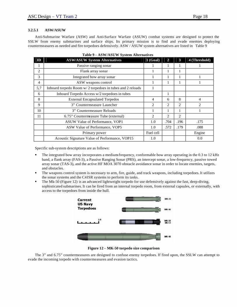
3.2.5.1 ASW/ASUW
Anti-Submarine Warfare (ASW) and Anti-Surface Warfare (ASUW) combat systems are designed to protect the SSLW from enemy submarines and surface ships. Its primary mission is to find and evade enemies deploying countermeasures as needed and fire torpedoes defensively. ASW / ASUW system alternatives are listed in Table 9
Table 9 - ASW/ASUW System Alternatives ID ASW/ASUW System Alternatives 1 (Goal) 2 3 4 (Threshold) 1 Passive ranging sonar 1 1 1 1 2 Flank array sonar 1 1 1
3 Integrated bow array sonar 1 1 1 1 4 ASW weapons control 1 1 1 1
5,7 Inboard torpedo Room w/ 2 torpedoes in tubes and 2 reloads 1
6 Inboard Torpedo Access w/2 torpedoes in tubes 1 8 External Encapsulated Torpedos 4 6 8 4 9 3” Countermeasure Launcher 2 2 2 2
10 3” Countermeasure Reloads 1 1 1 1 11 6.75” Countermeasure Tube (external) 2 2 2 ASUW Value of Performance, VOP1 1.0 .704 .196 .175 ASW Value of Performance, VOP5 1.0 .572 .179 .088 Primary power Fuel cell Engine Acoustic Signature Value of Performance, VOP15 1.0 0.0
Specific sub-system descriptions are as follows:
§ The integrated bow array incorporates a medium-frequency, conformable bow array operating in the 0.3 to 12 kHz band, a flank array (FAS-3), a Passive Ranging Sonar (PRS), an intercept sonar, a low-frequency, passive towed array sonar (TAS-3), and the active HF MOA 3070 obstacle avoidance sonar in order to locate enemies, targets, and obstacles.
§ The weapons control system is necessary to arm, fire, guide, and track weapons, including torpedoes. It utilizes the sonar systems and the C4ISR systems to perform its tasks.
§ The Mk-50 (Figure 12) is an advanced lightweight torpedo for use defensively against the fast, deep-diving, sophisticated submarines. It can be fired from an internal torpedo room, from external capsules, or externally, with access to the torpedoes from inside the hull.
Figure 12 - MK-50 torpedo size comparison
The 3” and 6.75” countermeasures are designed to confuse enemy torpedoes. If fired upon, the SSLW can attempt to evade the incoming torpedo with countermeasures and evasion tactics.

ASC Design – VT Team 2 Page 19
3.2.5.2 C4ISR
Command, Control, Communications, Computers and Intelligence (C4I), and Intelligence Surveillance, and Reconnaissance (ISR) includes a variety of reconnaissance components to gather and process information regarding enemy activity. These are the eyes and ears of SSLW.
§ The AD-16 PMP Photonics Mast, SHRIKE ESM/Comm Mast, and MMA all function to allow SSLW to monitor and communicate with ships and other assets or enemies on the surface. They are electronic and do not require a mast penetrating the hull into the Command space. This allows greatly flexibility in arranging the boat.
§ The Kollmorgen UAV is a small, disposable unmanned air vehicle that can be piloted remotely or operate autonomously. It folds into a cylinder only a few inches in diameter, and can be launched from a tube located on the submarine’s mast, allowing the crew to survey surface targets remotely over a large radius.
Table 10 - C4ISR System Alternatives ID C4ISR System Alternatives 1(Goal) 2(Threshold) 12 AD-16 PMP Photonics Mast 1 1 0 13 Kollmorgen UAV Mast -Launch capability Required by all designs 14 SHRIKE ESM and Comm Mast Required by all designs 15 Multifunction Mast Antenna (MMA) Required by all designs 16 ROPE Buoy System 1 17 UW Comms Required by all designs 18 Navigation Echo Sounders Required by all designs 19 Distress Beacon Required by all designs 20 Communications electronics and equipment Required by all designs 21 ISR Control and Processing Required by all designs 22 NPP Imaging Center 1 0 0
C4I Value of Performance, VOP2 1.0 0.405 0.164 ISR Value of Performance, VOP3 1.0 0.75 0.5
3.2.5.3 MCM
Mine Countermeasures (MCM) includes any activity to prevent or reduce the danger from enemy mines. Passive countermeasures operate by reducing a ship’s acoustic and magnetic signatures, while active countermeasures include mine avoidance, mine hunting, minesweeping, detection and classification, and mine neutralization. MCM system alternatives are listed in Table 11.
Table 11 - MCM System Alternatives ID MCM System Alternatives 1
(Goal) 2
(Threshold) 23 Mine Avoidance Forward Looking Sonar 1 1
24 Side Scan Sonar 1 MCM Value of Performance, VOP4 1.0 .33 Degaussing yes no Magnetic Signature Value of Performance, VOP14 1.0 0.0
Specific sub-system descriptions are as follows:
§ The mine avoidance forward looking sonar (Figure 13), and side scan sonar are two systems that can be utilized together to locate and avoid mines.
§ A degaussing system is a complex electrical system which allows a ship to cancel its magnetic signature. Steel hulls can develop a magnetic signature over time, and degaussing is usually employed during overhaul or refit periods to make the ship stealthier. Carrying this system onboard allows SSLW to maintain its magnetic signature independently.

ASC Design – VT Team 2 Page 20
Figure 13 - Forward Looking Sonar display
3.2.5.4 SPW
Special Operations Warfare (SPW) includes the delivery and support of Special Forces operations. The SSLW will have a distinct mission that will provide a platform for a platoon of Special Forces personnel. SPW system alternatives are listed in Table 12.
Table 12 – SPW System Alternatives ID SPW System Alternatives 1 (Goal) 2 3 4 (Threshold) 25 4-man lockout trunk 1 1 26 9-man lockout trunk 1 1 SEAL squad (officer + 7 enlisted) 2 2 1 1
27 Zodiac RHIB and diver stowage 4 4 2 2 SPW Value of Performance, VOP6 1.0 .8 .3 0.0
Specific sub-system descriptions are as follows:
§ A lockout chamber (Figure 14) is a space that can be sealed off and flooded with water to allow the deployment of divers while the submarine is submerged. A Special Forces squad consists of 8 people, so the 4-man lockout trunk would permit egress of an entire squad in two cycles.
§ The Special Force operations will also use a Combat Rubber Raiding Craft (CRRC). The CRRC is a small rigid hull inflatable boat (RHIB) powered by a hand-steered outboard motor, capable of carrying up to 8 Special Forces personnel and their gear.
Figure 14 - Lockout chamber arrangement

ASC Design – VT Team 2 Page 21
3.2.5.5 Mission Payload Modules
This design allows for the insertion of one 8x8x20ft Payload Interface Module. These modules allow the boat’s inherent capabilities to be enhanced depending on mission needs. Possible payloads include autonomous or remotely operated underwater vehicles, strike weapons, torpedoes, special warfare equipment stowage, or other modules.
Particular payloads of interest are those that enhance SSLW’s core missions. For MCM-related missions, a PIM could be carried that could be used to deploy and operate a myriad of anti-mine unmanned underwater vehicles such as REMUS, NMRS (Figure 15), or LMRS. PIMs could also be designed to allow special forces teams to store more equipment or weaponry, to enhance electronic surveillance and countermeasures capabilities, or perform ranged strike against land or sea targets.
Figure 15 - Near-Term Mine Reconnaissance System (NMRS)
3.2.5.6 Combat Systems Payload Summary
In order to trade-off combat system alternatives with other alternatives in the total ship design, combat system characteristics listed in Error! Reference source not found. are included in the ship synthesis model data base.
Table 13 - Combat System Ship Synthesis Characteristics

ASC Design – VT Team 2 Page 22
3.3 Design Space
A numerical value for each design variable within the specified range is selected by the optimizer and is transferred into ship synthesis model. The SSLW design has 20 design variables (Error! Reference source not found.). Hull design variables (DV1-5) are described in Section 3.2.1. The automation and manning factor, DV6, is described in Section 3.2.4. Stores and provisions duration, DV7, is described in Section 3.2.2. Combat System and Mission Alternatives, DV8-DV14, are described in Section 3.2.5. Propulsion and Machinery alternatives (DV 15 and 16) are described in Section 3.2.3.2.
Table 14 - Design Variables
Design Variable
Name Metric Description Trade-off Range
DV1 Lbow ft Length of bow section 25-40 DV2 Lmid feet Length of parallel midbody 30-45 DV3 Laft feet Length of aft section 40-70 DV4 B feet Beam 30-45 DV5 D feet Molded depth 17-25 DV6 Cmanning factor Manning reduction factor 0.5-1.0 DV7 T s days Time on station 14-24 DV8 ASW alternative Anti Surface/Submarine Warfare package 1-4 DV9 C4ISR alternative C4ISR package 1-3
DV10 MCM alternative MCM package 1-2 DV11 SPW alternative Special Warfare package 1-4 DV12 Depth feet Rated Depth 250-350 DV13 Ndegaus no/yes Degaussing system 0,1 DV14 PSYS alternative Propulsion system 1-6 (PEM, reformer, diesel)
DV15 BATtyp type Battery Type 1-3 (lithium ion, nickel cadmium, lead acid)
DV16 Ebattery kwhr Battery capacity 5000-15000 DV17 Ng number Number of generators 1-4 DV18 Wfuel lton Fuel weight 5.0-15.0 DV19 Npim number Number of PIM interfaces 1-4
3.4 Ship Synthesis Model
In Concept Exploration, a ship synthesis model is used to balance and assess designs selected by the optimizer. Ship synthesis model modules are integrated in Model Center (Figure 16). The Multi-Objective Genetic Optimization (MOGO) is also executed in Model Center. Measures of Performance (MOPs) are computed based on the design parameters and the predicted performance in a balanced design. Values of Performance (VOPs), an Overall Measure of Effectiveness (OMOE), Overall Measure of Risk (OMOR) and life cycle cost are computed by the ship synthesis model. To reject unacceptable designs, design feasibility margins are calculated, ensuring that a design that is produced that does not have the proper balance of characteristics (such as between weight and volume, speed and power, electrical load and power, etc.) is rejected as unfeasible. A small submarine synthesis model was developed specifically for this project.

ASC Design – VT Team 2 Page 23
Figure 16 - Ship Synthesis Model in Model Center (MC)
3.4.1 Input Module
The design requirements are inputs to the first module of the submarine synthesis model. In the Concept Exploration phase of the design process, the input requirements are changed frequently to meet the optimized condition of the model design.
3.4.2 Combat System Module
In the Combat System (CS) Module, input values are collected from the Combat System Data Base as specified by the combat system design variables. Selected CS components are assembled. Then, SWBS weight groups are updated with payload requirements. Warfighting VOPs based on selected alternatives are assigned. Inputs for the Combat System Module are ASW alternative, C4I alternative, ISR alternative, MCM alternative, SPW alternative, Number of PIM modules, and Molded depth. The calculated outputs are payload weights, VCGs, areas, power requirements, and warfighting VOPs.
3.4.3 Propulsion Module
The Propulsion Module reads propulsion system data based on input system type and battery type. It calculates propulsion system weight, volume and power characteristics and provides data to other modules in the ship synthesis model. Here are some input variables for the module: Propulsion system type, Battery type, Total battery capacity, Total fuel weight, Number of primary power generators, Overall propulsive coefficient, Transmission efficiency, Number of propulsors . With these variables, Propulsion Module computes the following output values: Total main generator power, Total battery power, Total weight basic propulsion machinery, Total battery weight, Total oxidant weight, Total argon weight, Total propulsion tank weight, Total machinery box volume, Total battery volume, Total propulsion and inboard volume, Generator specific fuel consumption, Required machinery box length, height, and width, Main generator power .
3.4.4 Hull Form Module
Hull form principal characteristics are calculated in Hull Form Module. It uses input dimensions to calculate principal dimensions, volumes, and surface area. Inputs for this module are bow section length, midsection length, aft length, beam, and molded depth. Examples of outputs are length overall (LOA), total surface area, envelope volume.

ASC Design – VT Team 2 Page 24
3.4.5 Electric Module
Electric Module calculates the required powers for specific onboard services such as steering, propulsion, fuel handling, and etc, based on parametric equations. Total services, sum, and additional margins are found through this process. The maximum functional electric load with margins is also calculated.
General inputs for Electric Module are functional margin factor, design margin factor, average power margin factor, total payload weight, number of propulsors, payload required power, pressure hull volume, machinery box volume, auxiliary space volume, total primary power, length overall, hull diameter, total crew, number of primary power generators, and degaussing. With these input variables, the following output values are calculated: maximum functional load with margins, average required power with margins, and primary generator required power rating.
3.4.6 Resistance Module
Resistance Module calculates hull resistance assuming primarily viscous resistance and using the ITTC frictional resistance equation with form factor. The form factor is calculated as a function of Beam/Length ratio. Outputs from the module include endurance shaft horsepower, sustained speed, endurance range and sprint range. Fuel and range calculations are based on DDS 200-1. In this module, a number of Input variables exist: Endurance speed, Resistance correlation allowance, Propulsion margin factor, Bare hull surface area, Average required electric power with margin, Overall length, Beam, Molded depth, Overall propulsive coefficient, Transmission efficiency, Total primary electric power, Primary generator specific fuel consumption, Sprint battery power, Battery capacity, Fuel weight, Total crew. From the input variables, following output values are obtained: Sustained speed, Effective shaft power, Sprint available brake propulsion power, Endurance range, Sprint range.
3.4.7 Weight and Stability Module
The weight and stability module calculates maximum and minimum ship weights, total weight, fuel weight, GM/GB, SWBS group weights, and normal surface condition weights. The module uses known weights and parametric equations to calculate the SWBS Group weights. There are a number of input variable for the module including operating depth, degaussing, total battery weight, total basic propulsion machinery weight, weight margin factor, everbuoyant volume, total sprint propulsion power available, maximum functional load with margins, overall length, molded depth, beam, pressure hull volume, payload structures weight, payload command and control weight, payload auxiliaries weight, ordnance delivery systems weight, total propulsion tanks weight, variable payload weight, lube oil weight, fresh water weight, fuel weight, oxidant weight, sewage weight, argon weight, total crew, number of officers, number of Enlisted, stores and provisions duration, average deck height, variable payload VCG.
3.4.8 Tankage Module
Tankage volumes and weights based on propulsion and manning inputs are computed in the tankage module. It uses input variables including miscellaneous propulsion inboard volume, manning and automation factor, total primary power, envelope volume, number of officers, number of enlisted specialists, mission, SPW, and oxidant weight. It uses parametric equations and computes the following output values: total tank volume excl. MBT, enlisted manning, total crew manning, lube oil weight, fresh water weight, and sewage weight.
3.4.9 Space Required Module
This module determines space requirements and initiates the space balance process. A parametric equation calculates volumes and areas using hull dimensions, manning, and other area inputs. Input variables for the module are: stores and provisions duration, average deck height, number of enlisted, number of officers, total crew, pressure hull arrangeable area margin, command and control payload required area, ordnance delivery system required area, machinery box volume, outboard payload volume, total tankage volume, propulsion total outboard volume, total battery volume, envelope volume, midbody length, aft body length, beam, molded depth. From these input variables the module calculates following output values: pressure hull volume, outboard volume, everbuoyant volume, MBT volume, submerged volume, free flood volume, free flood volume min and max, auxiliary volume, total required arrangeable area, total available arrangeable area
3.4.10 Feasibility Module
The feasibility module assesses the overall design feasibility of SSLW. Available characteristics and required characteristics are compared in terms of total arrangeable ship area, sustained speed, electrical plant power, endurance range, spring range. To do so, first all relevant model characteristics are inputted into the module and checking process against minimum and required constraints are performed. It also produces error measures that can be used to eliminate infeasible designs (E<0).

ASC Design – VT Team 2 Page 25
Input variables for the feasibility module are minimum endurance range, min sprint speed, min sprint range, min GB, min GM, min and max lead, min and max free flood volume, normal surface condition weight, total arrangeable area, total required arrangeable area, free flood volume, lead weight, sprint speed, primary generator power rating, required power, GM, GB, endurance range, and sprint range. With these input variables, following output values are calculated: arrangeable area error, minimum and maximum free flood error, min imum and maximum lead error, sprint speed error, KW error, GM error, GB error, endurance and sprint range error.
3.5 Multi-Objective Optimization
The Multi-Objective Genetic Optimizer (MOGO) is used to identify a non-dominated frontier of SSLW designs. These designs represent the maximum effectiveness for a given risk and cost. Because of the size of the SSLW design space, it is not feasible to assess every possible design for feasibility, effectiveness, risk and cost. A more efficient method is required. This is the reason for the genetic optimization process which is shown in Figure 17. The MOGO initially selects a random population of designs, then takes the best designs from this population and “breeds” them by combining their attributes to get the next population or generation. After several generations, the MOGO identifies a non-dominated frontier that is very similar to the non-dominated frontier that would be found if every possible design was evaluated, with significantly less calculation.
DefineSolution
Space
RandomPopulation
ShipSynthesis
Feasible?
Niche?
Fitness -Dominance
Layers
SelectionCrossoverMutation
Risk
Cost
Figure 17 - Multi-Objective Genetic Optimization (MOGO)
MissionDescription
OMOE Hierarchy
ROCs
Requirements and constraints for all
designs
MOPs,Goals &
Thresholds
DPs
VOPFunctions
OMOEFunction
MOPweights
MAVT
AHP
OMOR Hierarchy
Cost Model
Tentative Schedule
AHP
OMOR Weights
OMOR Function
Probabilities and
Consequences
Risk Index
Figure 18 - OMOE and OMOR Development Process
3.5.1 Overall Measure of Effectiveness (OMOE)
The Overall Measure of Effectiveness (OMOE) is a method of quantifying the effectiveness of each design that the optimizer considers. The measure of effectiveness is an index between zero and one describing ship effectiveness in specified missions using Equation 1. To quantify mission effectiveness, each ROC that varies for different designs is assessed using a Measure of Performance (MOP). The MOPs are specific ship or system performance metrics for required capabilit ies independent of the mission. For example ROC MOB 1 is to steam to design capacity in most fuel efficient
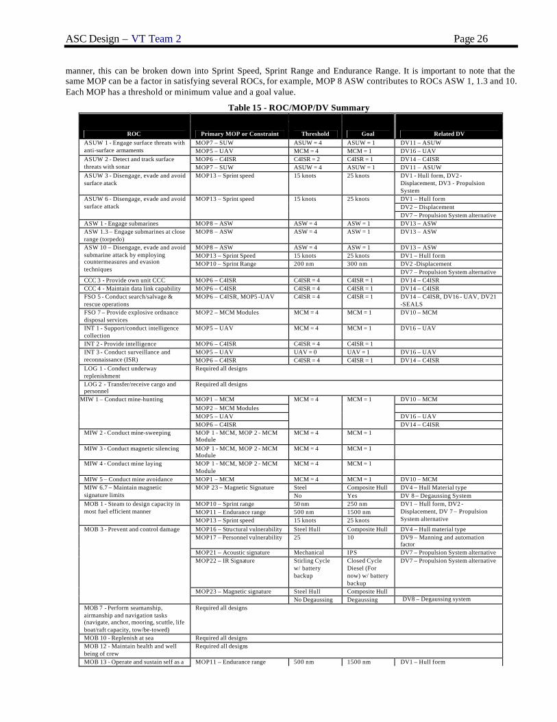
ASC Design – VT Team 2 Page 26
manner, this can be broken down into Sprint Speed, Sprint Range and Endurance Range. It is important to note that the same MOP can be a factor in satisfying several ROCs, for example, MOP 8 ASW contributes to ROCs ASW 1, 1.3 and 10. Each MOP has a threshold or minimum value and a goal value.
Table 15 - ROC/MOP/DV Summary
ROC Primary MOP or Constraint Threshold Goal Related DV MOP7 – SUW ASUW = 4 ASUW = 1 DV11 – ASUW ASUW 1 - Engage surface threats with
anti-surface armaments MOP5 – UAV MCM = 4 MCM = 1 DV16 – UAV MOP6 – C4ISR C4ISR = 2 C4ISR = 1 DV14 – C4ISR ASUW 2 - Detect and track surface
threats with sonar MOP7 – SUW ASUW = 4 ASUW = 1 DV11 – ASUW ASUW 3 - Disengage, evade and avoid surface atack
MOP13 – Sprint speed 15 knots 25 knots DV1 - Hull form, DV2 - Displacement, DV3 - Propulsion System DV1 – Hull form DV2 – Displacement
ASUW 6 - Disengage, evade and avoid surface attack
MOP13 – Sprint speed 15 knots 25 knots
DV7 – Propulsion System alternative ASW 1 - Engage submarines MOP8 – ASW ASW = 4 ASW = 1 DV13 – ASW ASW 1.3 – Engage submarines at close range (torpedo)
MOP8 – ASW ASW = 4 ASW = 1 DV13 – ASW
MOP8 – ASW ASW = 4 ASW = 1 DV13 – ASW MOP13 – Sprint Speed 15 knots 25 knots DV1 – Hull form MOP10 – Sprint Range 200 nm 300 nm DV2 -Displacement
ASW 10 – Disengage, evade and avoid submarine attack by employing countermeasures and evasion techniques DV7 – Propulsion System alternative CCC 3 - Provide own unit CCC MOP6 – C4ISR C4ISR = 4 C4ISR = 1 DV14 – C4ISR CCC 4 - Maintain data link capability MOP6 – C4ISR C4ISR = 4 C4ISR = 1 DV14 – C4ISR FSO 5 - Conduct search/salvage & rescue operations
MOP6 – C4ISR, MOP5 -UAV C4ISR = 4 C4ISR = 1 DV14 – C4ISR, DV16 - UAV, DV21 -SEALS
FSO 7 – Provide explosive ordnance disposal services
MOP2 – MCM Modules MCM = 4 MCM = 1 DV10 – MCM
INT 1 - Support/conduct intelligence collection
MOP5 – UAV MCM = 4 MCM = 1 DV16 – UAV
INT 2 - Provide intelligence MOP6 – C4ISR C4ISR = 4 C4ISR = 1 MOP5 – UAV UAV = 0 UAV = 1 DV16 – UAV INT 3 - Conduct surveillance and
reconnaissance (ISR) MOP6 – C4ISR C4ISR = 4 C4ISR = 1 DV14 – C4ISR LOG 1 - Conduct underway replenishment
Required all designs
LOG 2 - Transfer/receive cargo and personnel
Required all designs
MOP1 – MCM DV10 – MCM MOP2 – MCM Modules MOP5 – UAV DV16 – UAV
MIW 1 – Conduct mine-hunting
MOP6 – C4ISR
MCM = 4 MCM = 1
DV14 – C4ISR MIW 2 - Conduct mine-sweeping MOP 1 - MCM, MOP 2 - MCM
Module MCM = 4 MCM = 1
MIW 3 - Conduct magnetic silencing MOP 1 - MCM, MOP 2 - MCM Module
MCM = 4 MCM = 1
MIW 4 - Conduct mine laying MOP 1 - MCM, MOP 2 - MCM Module
MCM = 4 MCM = 1
MIW 5 – Conduct mine avoidance MOP1 – MCM MCM = 4 MCM = 1 DV10 – MCM Steel Composite Hull DV4 – Hull Material type MIW 6.7 – Maintain magnetic
signature limits MOP 23 – Magnetic Signature
No Yes DV 8 – Degaussing System MOP10 – Sprint range 50 nm 250 nm MOP11 – Endurance range 500 nm 1500 nm
MOB 1 - Steam to design capacity in most fuel efficient manner
MOP13 – Sprint speed 15 knots 25 knots
DV1 – Hull form, DV2 - Displacement, DV 7 – Propulsion System alternative
MOP16 – Structural vulnerability Steel Hull Composite Hull DV4 – Hull material type MOP17 – Personnel vulnerability 25 10 DV9 – Manning and automation
factor MOP21 – Acoustic signature Mechanical IPS DV7 – Propulsion System alternative MOP22 – IR Signature Stirling Cycle
w/ battery backup
Closed Cycle Diesel (For now) w/ battery backup
DV7 – Propulsion System alternative
MOP23 – Magnetic signature Steel Hull Composite Hull
MOB 3 - Prevent and control damage
No Degaussing Degaussing DV8 – Degaussing system MOB 7 - Perform seamanship, airmanship and navigation tasks (navigate, anchor, mooring, scuttle, life boat/raft capacity, tow/be-towed)
Required all designs
MOB 10 - Replenish at sea Required all designs MOB 12 - Maintain health and well being of crew
Required all designs
MOB 13 - Operate and sustain self as a MOP11 – Endurance range 500 nm 1500 nm DV1 – Hull form

ASC Design – VT Team 2 Page 27
DV2 – Displacement DV7 – Propulsion System alternative
forward deployed unit for an extended period of time during peace and war without shore-based support MOP12 – Provisions 14 days 24 days DV18 – Provisions Duration MOB 14 - Operate in a Piggy -Back configuration
Required all designs
MOB 16 - Operate in day and night environments
Required all designs
MOB 18 - Operate in full compliance of existing US and international pollution control laws and regulations
Required all designs
NCO 3 - Provide upkeep and maintenance of own unit
Required all designs
SEW 2 - Conduct sensor and ECM operations
Required all designs
SEW 3 – Conduct sensor and ECCM operations
Required all designs
SPW 1 - Provide lock out chamber Required all designs SPW 2 - Habitability Module Required all designs SPW 3 – Deploy Special Forces troops Required all designs
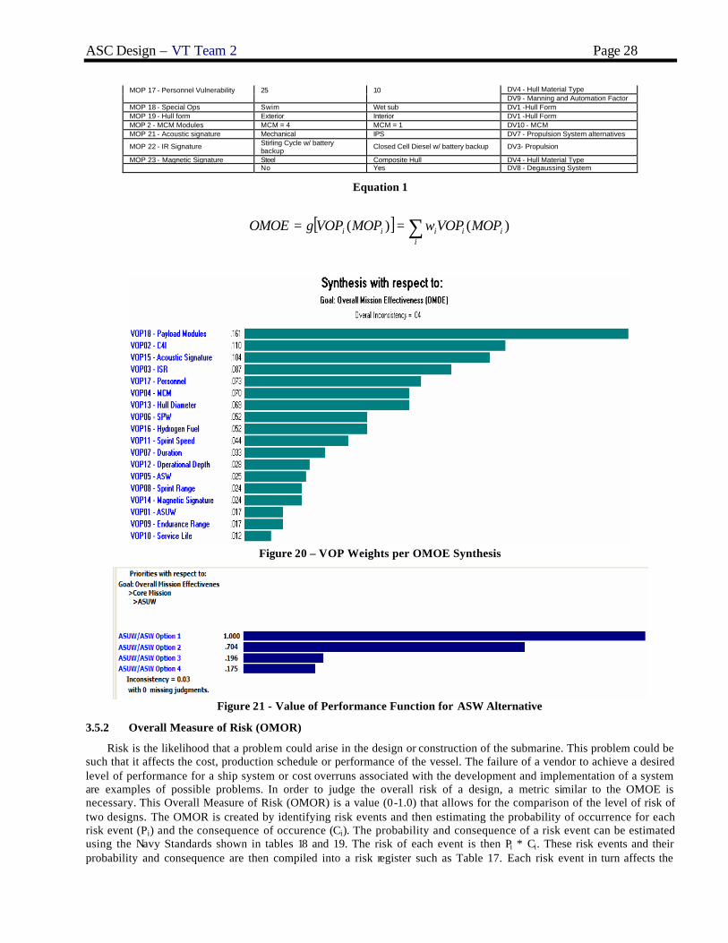
Values of performance (VOP) are figures of merit indexes specifying the value of a specific MOP to a specific mission area for a specific type of mission. These VOPs are values between zero and one with one corresponding to the goal value and zero corresponding to the threshold value. Values of performance for values between the goal and threshold values are calculated from functions that are created from expert opinions. The MOPs used to determine the OMOE for each design are shown in Table 16. Each MOP is weighted via pairwise comparison to give a relative importance to the overall effectiveness of the design. Each MOP is based on the balanced ship produced from the design variables. The related design variables used in the optimizer are also shown in Table 16.
Figure 19 - OMOE Hierarchy
Table 16 - MOP Table Primary MOP or Constraint Threshold or Constraint Goal Related DV
MOP 01 - MCM MCM = 4 MCM = 1 DV10 - MCM MOP 06 - C4ISR C4ISR = 2 C4ISR = 1 DV14 - C4ISR MOP 08 - ASW ASW = 4 ASW = 4 DV13 - ASW MOP 10 - Sprint Range 200 nm 300 nm DV2 - Displacement MOP 11 - Endurance Range 500 nm 1500 nm DV1 -Hull Form MOP 12 - Provisions
14 days
24 days
DV2 - Displacement
DV3- Propulsion DV18 - Provisions Duration
MOP 13 - Sprint Speed 15 knots
25 knots
DV1 -Hull Form MOP 16 - Structural Vulnerability
Steel
Composite Hull
DV2 - Displacement
DV3- Propulsion
ASC Design – VT Team 2 Page 28
DV4 - Hull Material Type MOP 17 - Personnel Vulnerability 25 10 DV9 - Manning and Automation Factor
MOP 18 - Special Ops Swim Wet sub DV1 -Hull Form MOP 19 - Hull form Exterior Interior DV1 -Hull Form MOP 2 - MCM Modules MCM = 4 MCM = 1 DV10 - MCM MOP 21 - Acoustic signature Mechanical IPS DV7 - Propulsion System alternatives
MOP 22 - IR Signature Stirling Cycle w/ battery backup
Closed Cell Diesel w/ battery backup DV3- Propulsion
MOP 23 - Magnetic Signature Steel Composite Hull DV4 - Hull Material Type No Yes DV8 - Degaussing System
Equation 1
[ ] ∑==i
iiiii MOPVOPwMOPVOPgOMOE )()(
Figure 20 – VOP Weights per OMOE Synthesis
Figure 21 - Value of Performance Function for ASW Alternative
3.5.2 Overall Measure of Risk (OMOR)
Risk is the likelihood that a problem could arise in the design or construction of the submarine. This problem could be such that it affects the cost, production schedule or performance of the vessel. The failure of a vendor to achieve a desired level of performance for a ship system or cost overruns associated with the development and implementation of a system are examples of possible problems. In order to judge the overall risk of a design, a metric similar to the OMOE is necessary. This Overall Measure of Risk (OMOR) is a value (0-1.0) that allows for the comparison of the level of risk of two designs. The OMOR is created by identifying risk events and then estimating the probability of occurrence for each risk event (Pi) and the consequence of occurence (Ci). The probability and consequence of a risk event can be estimated using the Navy Standards shown in tables 18 and 19. The risk of each event is then Pi * Ci. These risk events and their probability and consequence are then compiled into a risk register such as Table 17. Each risk event in turn affects the
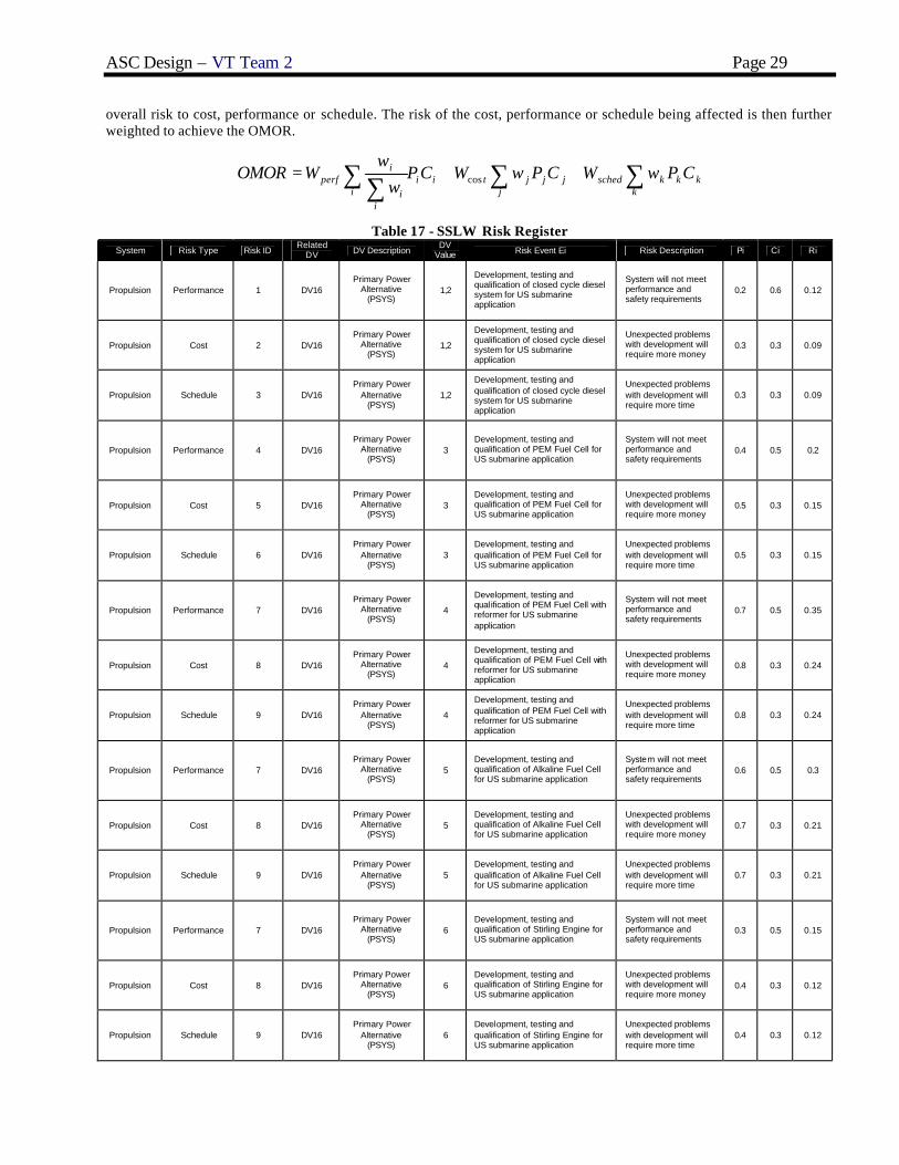
ASC Design – VT Team 2 Page 29
overall risk to cost, performance or schedule. The risk of the cost, performance or schedule being affected is then further weighted to achieve the OMOR.
kkk
kschedjjj
jtiii
ii
iperf CPwWCPwWCP
ww
WOMOR ∑∑∑ ∑++= cos
Table 17 - SSLW Risk Register System Risk Type Risk ID
Related DV DV Description
DV Value Risk Event Ei Risk Description Pi Ci Ri
Propulsion Performance 1 DV16 Primary Power
Alternative (PSYS)
1,2
Development, testing and qualification of closed cycle diesel system for US submarine application
System will not meet performance and safety requirements
0.2 0.6 0.12
Propulsion Cost 2 DV16 Primary Power
Alternative (PSYS)
1,2
Development, testing and qualification of closed cycle diesel system for US submarine application
Unexpected problems with development will require more money
0.3 0.3 0.09
Propulsion Schedule 3 DV16 Primary Power
Alternative (PSYS)
1,2
Development, testing and qualification of closed cycle diesel system for US submarine application
Unexpected problems with development will require more time
0.3 0.3 0.09
Propulsion Performance 4 DV16 Primary Power
Alternative (PSYS)
3 Development, testing and qualification of PEM Fuel Cell for US submarine application
System will not meet performance and safety requirements
0.4 0.5 0.2
Propulsion Cost 5 DV16 Primary Power
Alternative (PSYS)
3 Development, testing and qualification of PEM Fuel Cell for US submarine application
Unexpected problems with development will require more money
0.5 0.3 0.15
Propulsion Schedule 6 DV16 Primary Power
Alternative (PSYS)
3 Development, testing and qualification of PEM Fuel Cell for US submarine application
Unexpected problems with development will require more time
0.5 0.3 0.15
Propulsion Performance 7 DV16 Primary Power
Alternative (PSYS)
4
Development, testing and qualification of PEM Fuel Cell with reformer for US submarine application
System will not meet performance and safety requirements
0.7 0.5 0.35
Propulsion Cost 8 DV16 Primary Power
Alternative (PSYS)
4
Development, testing and qualification of PEM Fuel Cell with reformer for US submarine application
Unexpected problems with development will require more money
0.8 0.3 0.24
Propulsion Schedule 9 DV16 Primary Power
Alternative (PSYS)
4
Development, testing and qualification of PEM Fuel Cell with reformer for US submarine application
Unexpected problems with development will require more time
0.8 0.3 0.24
Propulsion Performance 7 DV16 Primary Power
Alternative (PSYS)
5 Development, testing and qualification of Alkaline Fuel Cell for US submarine application
System will not meet performance and safety requirements
0.6 0.5 0.3
Propulsion Cost 8 DV16 Primary Power
Alternative (PSYS)
5 Development, testing and qualification of Alkaline Fuel Cell for US submarine application
Unexpected problems with development will require more money
0.7 0.3 0.21
Propulsion Schedule 9 DV16 Primary Power
Alternative (PSYS)
5 Development, testing and qualification of Alkaline Fuel Cell for US submarine application
Unexpected problems with development will require more time
0.7 0.3 0.21
Propulsion Performance 7 DV16 Primary Power
Alternative (PSYS)
6 Development, testing and qualification of Stirling Engine for US submarine application
System will not meet performance and safety requirements
0.3 0.5 0.15
Propulsion Cost 8 DV16 Primary Power
Alternative (PSYS)
6 Development, testing and qualification of Stirling Engine for US submarine application
Unexpected problems with development will require more money
0.4 0.3 0.12
Propulsion Schedule 9 DV16 Primary Power
Alternative (PSYS)
6 Development, testing and qualification of Stirling Engine for US submarine application
Unexpected problems with development will require more time
0.4 0.3 0.12
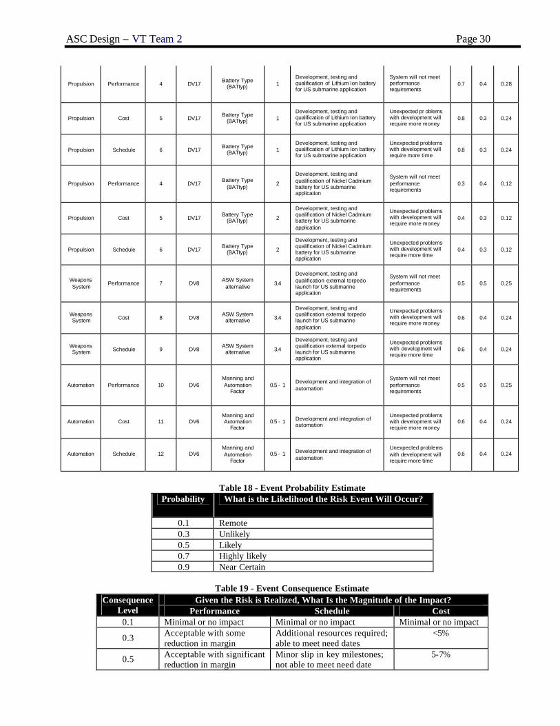
ASC Design – VT Team 2 Page 30
Propulsion Performance 4 DV17 Battery Type
(BATtyp) 1 Development, testing and qualification of Lithium Ion battery for US submarine application
System will not meet performance requirements
0.7 0.4 0.28
Propulsion Cost 5 DV17 Battery Type
(BATtyp) 1 Development, testing and qualification of Lithium Ion battery for US submarine application
Unexpected pr oblems with development will require more money
0.8 0.3 0.24
Propulsion Schedule 6 DV17 Battery Type
(BATtyp) 1 Development, testing and qualification of Lithium Ion battery for US submarine application
Unexpected problems with development will require more time
0.8 0.3 0.24
Propulsion Performance 4 DV17 Battery Type
(BATtyp) 2
Development, testing and qualification of Nickel Cadmium battery for US submarine application
System will not meet performance requirements
0.3 0.4 0.12
Propulsion Cost 5 DV17 Battery Type
(BATtyp) 2
Development, testing and qualification of Nickel Cadmium battery for US submarine application
Unexpected problems with development will require more money
0.4 0.3 0.12
Propulsion Schedule 6 DV17 Battery Type
(BATtyp) 2
Development, testing and qualification of Nickel Cadmium battery for US submarine application
Unexpected problems with development will require more time
0.4 0.3 0.12
Weapons System
Performance 7 DV8 ASW System
alternative 3,4
Development, testing and qualification external torpedo launch for US submarine application
System will not meet performance requirements
0.5 0.5 0.25
Weapons System Cost 8 DV8
ASW System alternative 3,4
Development, testing and qualification external torpedo launch for US submarine application
Unexpected problems with development will require more money
0.6 0.4 0.24
Weapons System Schedule 9 DV8
ASW System alternative 3,4
Development, testing and qualification external torpedo launch for US submarine application
Unexpected problems with development will require more time
0.6 0.4 0.24
Automation Performance 10 DV6 Manning and Automation
Factor 0.5 - 1
Development and integration of automation
System will not meet performance requirements
0.5 0.5 0.25
Automation Cost 11 DV6 Manning and Automation
Factor 0.5 - 1 Development and integration of
automation
Unexpected problems with development will require more money
0.6 0.4 0.24
Automation Schedule 12 DV6 Manning and Automation
Factor 0.5 - 1 Development and integration of
automation
Unexpected problems with development will require more time
0.6 0.4 0.24
Table 18 - Event Probability Estimate Probability What is the Likelihood the Risk Event Will Occur?
0.1 Remote 0.3 Unlikely 0.5 Likely 0.7 Highly likely 0.9 Near Certain
Table 19 - Event Consequence Estimate Given the Risk is Realized, What Is the Magnitude of the Impact? Consequence
Level Performance Schedule Cost 0.1 Minimal or no impact Minimal or no impact Minimal or no impact
0.3 Acceptable with some reduction in margin
Additional resources required; able to meet need dates
<5%
0.5 Acceptable with significant reduction in margin
Minor slip in key milestones; not able to meet need date
5-7%

ASC Design – VT Team 2 Page 31
0.7 Acceptable; no remaining margin
Major slip in key milestone or critical path impacted
7-10%
0.9 Unacceptable Can’t achieve key team or major program milestone
>10%
3.5.3 Cost
Lead ship acquisition cost plus life cycle battery replacement cost is used as the cost objective attribute. It is calculated for SSLW as shown in Figure 22. Weights for each of the SWBS groups are used to calculate material cost and labor cost. The total direct cost of the ship is the sum of the cost of labor and the cost of material. To find the indirect cost, an overhead margin is applied. Overhead costs account for all extraneous expenditures beyond the actual labor and material costs. Profit equal to 10% of the total direct and overhead costs is added to calculate the Basic Cost of Construction (BCC). A life cycle cost component for battery replacement is added to BBC.
Figure 22 - SSLW Cost Model
3.6 Optimization Results
The MOGO produced a non-dominated frontier as seen in Figure 23. Design 38 is indicated by a red circle. This design has higher cost than most others in the NDF, but also features a high level of effectiveness compared to its overall measure of risk. The design was chosen by looking for “knees” in the curves of the D=13ft. designs. Its effectiveness is matched or beaten by many of the significantly cheaper D=21ft designs, but they all incur almost double the risk for relatively small effectiveness gains.

ASC Design – VT Team 2 Page 32
0.4
0.45
0.5
0.55
0.6
0.65
0.7
0.75
0.8
200 250 300 350 400 450
BCC ($M)
OM
OE
Low Risk D=21Medium Risk D=21Medium High Risk D=21High Risk D=21Highest Risk D=21Low Risk D=13Low Medium Risk D=13Medium Risk D=13Medium High Risk D=13Highest Risk D=13
Figure 23 - Non-Dominated Frontier
3.7 Design 38 Baseline Concept Design
Pertinent baseline design characteristics can be seen in the following tables. Baseline design 38 was dubbed “Submersible Covert Reconnaissance – Alternative Platform” or SCRAP by team 4.
Table 20 - Design Variable Summary
Design Variable
Description Trade-off Range Your Design Values
DV1 Length of bow section (ft) 25-40 31 DV2 Length of parallel midbody (ft) 30-45 64 DV3 Length of aft section (ft) 40-70 74 DV4 Beam (ft) 30-45 28 DV5 Molded depth (ft) 17-25 13 DV6 Manning reduction factor 0.5-1.0 0.59 DV7 Time on stat ion (days) 14-24 26
DV8 Anti Surface/Submarine Warfare package (option) 1-4 2
DV9 C4ISR package (option) 1-3 3 DV10 MCM package (option) 1-2 2 DV11 Special Warfare package (option) 1-4 3 DV12 Rated Depth (ft) 250-350 290 DV13 Degaussing system (0=no, 1=yes) 0,1 1 DV14 Propulsion system (option) 1-6 (PEM, reformer, diesel) 4 (PEM w/ reformer)
DV15 Battery Type (option) 1-3 (lithium ion, nickel cadmium, lead acid)
3 (lead acid)
DV16 Battery capacity (kWhr) 5000-15000 5700 DV17 Number of generators (number) 1-4 1 DV18 Fuel weight (lton) 5.0-15.0 15 DV19 Number of PIM interfaces (number) 1-4 1
Table 21 - Concept Exploration Weights and Vertical Center of Gravity Summary
Group Weight (lton) VCG (ft) SWBS 100 309 5.2 SWBS 200 201 4.9 SWBS 300 36.6 9.2 SWBS 400 17.5 6.7 SWBS 500 53.5 6.6 SWBS 600 43.6 5.98 SWBS 700 3.57 9.1 SWBS 800 51.9 5.5

ASC Design – VT Team 2 Page 33
Condition A1 665 Condition A 717 Normal Surface Condition 843 5.16
Table 22 - Concept Exploration Area Summary
Area Required Available Total-Arrangeable 1783 2206
Table 23 - Concept Exploration Electric Power Summary
Group Description Power SWBS 200 Propulsion 1.08 SWBS 300 Electric Plant, Lighting 4.00 SWBS 430, 475 Miscellaneous 15.4 SWBS 521 Firemain 1.94 SWBS 540 Fuel Handling 2.00 SWBS 530, 550 Miscellaneous Auxiliary 9.09 SWBS 561 Steering 17.6 SWBS 600 Services 5.53 Deguassing Degaussing 40.0 KWNP Non-Payload Functional Load 56.6 KWMFLM Max. Functional Load w/Margins 220. KW24 24 Hour Electrical Load 100.
Table 24 - Concept Exploration Baseline Design Principal Characteristics
Characteristic Baseline Value Hull form Catamaran, single -deck WNSC (lton) 843 LOA (ft) 169 Beam (ft) 28 Molded Depth (ft) 13 Length to Beam Ratio 6.04 W1 (lton) 309 W2 (lton) 201 W3 (lton) 36.6 W4 (lton) 17.5 W5 (lton) 53.5 W6 (lton) 43.6 W7 (lton) 3.57 Wp (lton) 51.9 Condition A (lton) 717 KG (ft ) 5.16 GB (ft) 1.03 Propulsion system PEM Fuel Cell w/ Reformer Propulsor Dual shrouded propulsors w/
DPJP/ducted thrusters ASW system 2 (VOP=0.111) MCM system 2 (VOP=0.333) C4ISR system 3 (VOP=0.694) SPW system 3 (VOP=1) Total Officers 3 Total Enlisted 9 Total Manning 12 (plus eight special forces

ASC Design – VT Team 2 Page 34
Characteristic Baseline Value personnel)
Number of PIMs 1 Ship Acquisition Cost $196M Life Cycle Cost $369M

ASC Design – VT Team 2 Page 35
4 Concept Development (Feasibility Study) Concept Development of SCRAP follows the design spiral, seen in Figure 24, in sequence after Concept Exploration.
In Concept Development the general concepts for the hull, systems and arrangements are developed. These general concepts are refined into specific systems and subsystems that meet the ORD requirements. Design risk is reduced by this analysis and parametrics used in Concept Exploration are validated.
Figure 24 - Submarine design spiral
4.1 General Arrangement and Combat Operations Concept (Cartoon)
The general arrangement concept for the Littoral Warfare submarine was not derived from the traditional US Navy submarine arrangements. These general arrangement designs are dictated by a submarine’s unique size, shape, and using the space as effectively as possible. The shape chosen for the SCRAP submarine concept is far different from anything the US Navy has explored in the past. SCRAP will be separated into two compartments, divided by a transverse bulkhead. The aft compartment, the Engine Room (ER), is dedicated to the main propulsion and all that it encompasses; including the fuel cells, bus panels, potable water system, and the majority of the auxiliary machinery. The bow compartment, called the Operational Compartment (OC), holds all the men and material necessary to complete the mission. This includes mission systems, electronic equipment, berthing, messing, and the control room. Another key component in the submarine ‘cartoon’ design is the Payload Interface Module, located in the center of the hull. This location was chosen because it provided the least effect on the boat’s list and trim during loading and unloading of payloads. The variable ballast tanks (VL) are located forward and aft at the ends of the hull, as well as a Payload Compensation Tank (PLC) that surrounds the Payload Interface Module. This tank is designed as a hard tank to take in seawater to the trim and drain system, and to compensate the weight of expended payloads. While the Main Ballast Tanks allow SCRAP to surface and submerge, the variable ballast is designed to prevent trim and list situations. These tanks are usually located at opposite ends of the submarine to offer the greatest moment to counteract other forces. The basic cartoon, in profile view, is shown in Figure 25.

ASC Design – VT Team 2 Page 36
Figure 25 - Cartoon for SCRAP
The desired layout of the Engine Room is different from anything the US Navy has previously deployed. The US Navy has never deployed a PEM or Reformer; therefore the arrangements of the machinery spaces will differ greatly from their nuclear counterparts. Overall the volume of the ER is significantly smaller than that of its nuclear brethren. On current submarines, the Operational Compartment is dictated by the placement of the periscopes, forcing the control room to be located at this point. With the transformational technologies aboard SCRAP, the layout can be more functional.
4.1.1 Mission Operations
SCRAP will also have very unique mission systems because of its particular missions. To support the Special Forces operations, the submarine will have an extremely large diver lockout chamber and a specially configured sail packed with their gear. The Intelligence, Surveillance, and Reconnaissance (IRS) missions will require sophisticated electronics in the Control Room to work in conjunction with the different masts and Mission Augmentation Buoy. The third designated mission is the UUV operations, which will require the support electronics and storage facilities. The final mission system would be the offensive/defensive weapons; ten Mark-50 torpedoes and their fire control electronics, with 4 in internal tubes, and 6 housed externally.
To support the Special Forces missions, SCRAP will have some systems and modifications that other submarines in the fleet do not have. For getting the Special Force operators out of the submarine as fast possible, a 4 diver lockout chamber will be incorporated into the hull. This chamber would have internal and external pressure hatches much larger then standard Navy hatches to allow the operators to enter and exit the chamber with ease. The chamber itself will be located on the centerline of the port hull and slightly forward of the center of gravity, being placed there to keep the submarine as stable as possible. The sail was also specifically designed to hold two Combat Rubber Raiding Craft for the Special Force operators. This small boat will allow the operators a covert surface insertion capability. The CRRC will be stored in the sail’s aft section, which will open claw-shell style and have the ability to be operated either submerged or on the surface.
The ISR mission systems will focus on the submarine’s ‘eyes and ears’; the communication masts and periscopes. Just as with the machinery and electrical systems, COTS technologies will be employed as much as possible to keep cost down and have upgradeability. The Kollmorgen Electro-Optical company produces a fully digital periscope system for the US Navy’s Virginia Class submarines. This system has a variety of different cameras for all lighting and environmental conditions, including high definition black and white, color, infrared, and thermal imaging. In the control room of the SSLW there will be 180° wrap-around monitor for the Officer of the Deck to watch instead of putting his eye into the lens of a periscope and have only a pinhole sized view of the surface. SCRAP will have two redundant masts mounted directly within the sail. These masts are non-penetrating, so the control room may be divorced from the sail’s location. These masts hold the digital cameras, the Electronic Surveillance Measures (ESM) receiver, the communications antennas, and the GPS receiver. The ESM system will be able to recognize the electronic signals radiating from the enemy’s coastline and classify them, allowing the crew to tell the fleet of the enemy’s radar and communication capabilities. Communications is vital to the Littoral Warfare submarine in staying connected with the rest of the fleet and with the overall command. The antenna will be capable across a wide range of frequencies as well as the ability to link to satellites. Navigation will be based off of a Garmin commercially available GPS system where the small receiver will be mounted in either mast.
The UUV mission systems demand other considerations in the overall design. These UUVs will be deployed out of the submarine through the Payload interface module, or the Kollmorgen Electro-Optical mast. To operate the UUVs, an electronics system will be built into the Control Room with all the rest of the ship control systems. Extra berths in the crew quarters will allow for any personnel who are specific to the UUV operations to come onboard.

ASC Design – VT Team 2 Page 37
Though SCRAP has very specific missions, it is required to have some sort of offensive/defensive weapons. To fulfill this requirement the submarine will carry specially modified Mark-50 torpedoes. The Mk-50 was originally a surface or air launched lightweight torpedo, mounted in launch tubes or hung from a weapon hard-point on a plane or helicopter. But for use onboard SCRAP, six torpedoes will each be stored in a pressure resistant canister mounted within the hull. The fire control system will be located in the Control Room and will be integrated with all the other electronics onboard the submarine so that any of the work stations will be able to fire the torpedoes. The four conventional tubes will be operated in the same manner as their larger counterparts in an attack submarine. Conformal Bow arrays, Passive ranging sonar, and flank arrays comprise the sonar suite, allowing defensive ASW operations. Mine avoidance sonar is also utilized, as the littoral environment is often a heavily mined area. SCRAP has been designed with the ability to utilize NMRS, LMRS, or other anti-mine unmanned vehicles within PIM or externally encapsulated in the hull.
4.1.2 Machinery Room Arrangements
There are two machinery rooms, MMR#1 and MMR#2, located aft of amidships. The rooms are parallel to each other and each contains a propulsion motor and DC/AC inverter. In addition to these, the main machinery rooms contain two power conversion modules, motor control center and a lighting load panel.
The auxiliary machinery room houses some of the pumps used by the submarine. This includes the trim and drain pumps, seawater cooling pumps, freshwater pumps, main hydraulic pump, hydraulic pressure accumulator and the high pressure air compressor. The reverse osmosis distiller is also located in this room.
The PEM room contains the PEM fuel cells, regenerator, and the DC (400V) main switchboard.
Machinery arrangements are discussed in more detail in section 4.7.3.
4.2 Hull Form
The hull form chosen for SCRAP is a flattened oval shape rather then the cylindrical hull normally associated with submarines. Mission requirements demand that the submarine be able to operate in waters less then 100 feet deep, which requires a small molded depth. To accomplish this while also allowing enough arrangeable deck area, a single deck, flattened oval hull form is chosen. An ordinary oval shape was considered, but concerns with excess structural weight and the need for large stanchions called for a more innovative design. A catamaran hull was chosen because it allowed for a large useable deck area in a small hull depth, and provided good structural efficiency for a non-cylindrical design.
The catamaran design is made of three hulls connected together. The two larger outer hulls are 13 feet in diameter, and the smaller inner hull is 7.5 feet in diameter. The hulls join together where the tangent lines from the outer hull would pass through the center point of the center hull, minimizing shear stress, as seen in Figure 26.
Figure 26 - Hullform Cross Section
The entire pressure load is carried by the hoop stress, just like in a cylindrical hull. The hull itself would be 13 feet tall, 29 feet wide, and 142 feet long; with a sail increasing the height another 5 feet. At the bow, the submarine would have a relatively sharp nose, then 98 feet of parallel midbody, then slope down to a wide flat stern. Research shows that the length of the sloping stern should be approximately 2 times the diameter. In this case, the height was used as the ‘diameter’ and the length of the stern section was determined to be 24 feet.

ASC Design – VT Team 2 Page 38
4.3 Structural Design and Analysis
The structural design process for SCRAP is illustrated in Figure 27. The structural design and analysis was performed in a program called MAESTRO, a coarse-mesh finite element solver and modeler with the ability to assess individual failure modes. After creating the model, stresses are analyzed and then adequacy is assessed for each failure mode. After analyzing the adequacy of each element, the scantlings are adjusted and the hull can be re-evaluated.
Geometry
Components / Materials
Loads
StressesModes of
FailureStrength
Scantling Iteration
Figure 27 - Structural Design Process
4.3.1 Geometry, Components and Materials
The primary hulls are partial cylinders. The tangency line from the intersection of each primary hull with the center hull runs through the geometric center of the center hull. This tangency allows the X frames to transfer the hoop stress from one primary hull to the other which eliminates shear stress. The pressure hull is completely constructed of HY-80 steel. The pressure hull plate is 1 inch thick with ring frames spaced every 13 inches in the forward and aft sections and every 12 inches in the PIM section of the hull. King frames are located one frame in from the forward and aft endcap and at the forward and aft ends of the PIM. There are no internal structural bulkheads in the pressure hull. It was predicted that MAESTRO may not handle the hemispherical endcaps in the design, so the endcaps were modeled as flat bulkheads.
Table 25 - Scantlings for SCRAP
Stiffener Web
Height (in)
Web Thickness
(in)
Flange Width
(in)
Flange Thickness
(in)
King Frames 12.0 2.0 8.0 2.0 Ring Frames 5.15 0.27 5.03 0.43
X-Frames 9.6 9.6 Longitudinals 14.06 0.418 10.04 0.718

ASC Design – VT Team 2 Page 39
Figure 28 – Pressure Hull Structural Model
4.3.2 Loads
The primary load case for a pressure hull is the pressure and primary structure self weight load at test depth. It is assumed that this is the worst case loading scenario for the submarine. The non-pressure hull was not designed at this stage so hogging and sagging conditions where not considered.
Figure 29 - Load on pressure hull from depth

ASC Design – VT Team 2 Page 40
4.3.3 Adequacy
MAESTRO calculates the stresses caused by each load case and compares them to the limit state values for the various failure modes. Dividing stress by the failure stress for each failure mode yields the strength ratio, r, for that mode. MAESTRO then calculates an adequacy parameter to normalize the results. This parameter is defined as (1-r)/(1+r). This parameter always varies from negative one to positive one. Values close to negative one indicate that an element is extremely inadequate while values close to positive one are extremely over designed. The ideal adequacy value is zero which indicates that the element meets the required strength with a given factor of safety. At this level of design the goal is to make the adequacy as close to zero as possible while keeping it positive. In a more detailed analysis the objective would be to drive the adequacy parameters to zero everywhere. For this submarine the buckling and stiffener failure factors of safety were 2.5 while the membrane yield factor of safety was 1.5. Figure 30 shows the minimum values for plate and beam failure modes for all load cases.
Figure 30 - Plate and beam adequacy
4.4 Power and Propulsion
SCRAP uses an Integrated Power System (IPS) for primary propulsion as well as for ship service power. Power is created by a single 250kW Proton Exchange Membrane (PEM) fuel cell with reformer. Two direct drive permanent magnet motors that are sized for the power requirements power the twin screws.
4.4.1 Resistance
Resistance, speed and power calculations are performed using analytical calculations. Frictional resistance calculations used the ITTC Line, and residuary resistance data was obtained from several empirical analyses performed on a very similar hull design. A standard correlation allowance of 0.0004 was chosen, and a total resistance was calculated. As seen in Appendix G, this resistance calculation was then compared to two independent axisymmetric analytical algorithms, one developed at Virginia Tech, and another developed at MIT. The method developed at Virginia Tech based its algorithm off of a form factor from Gilmer and Johnson in order to find the residual resistance. The MIT method used its own form factor for the calculation. As can be seen from the speed versus power curve in Figure 31, the analytical calculations are all within 5% of each other at the designed sprint speed, and the difference in results are due to the Virginia Tech and MIT method being designed for axisymmetric hull designs. An additional 10% margin is added to the resistance calculation for the endurance speed/fuel calculation and a 25% margin is added for the sustained speed calculation.

ASC Design – VT Team 2 Page 41
Viscous Resistance vs. Speed y = 118.33x1.9061
R2 = 1
0
5000
10000
15000
20000
25000
30000
35000
40000
0 5 10 15 20
Speed (kn)
Vis
cou
s R
esis
tan
ce (l
b)
Figure 31 - Plot of resistance vs. speed
Figure 32 - Plot of EHP vs. speed
4.4.2 Propulsion
The pair of propellers was designed from the B4-55 propeller chart from Principles of Naval Architecture, Volume II. Each propeller is 6.5 ft in diameter, and is powered by a direct drive permanent magnet motor. After the specific four bladed propeller charts were chosen, open-water efficiency was estimated and then iterated in order to find the best propeller characteristics for the design. The calculations and characteristics of the propeller design can be seen in Appendix G. Figure 33 shows shaft propulsion power vs. engine speed, including the 25% sustained speed margin. A more complete propulsion system description and arrangements are provided in Section 4.5 and 4.7.3.

ASC Design – VT Team 2 Page 42
Shaft Horsepower vs. Engine Speed
0
1000
2000
3000
4000
5000
6000
190 240 290 340 390 440 490 540
Engine Speed (rpm)
Sh
aft
Ho
rsep
ow
er, S
HP
(h
p)
Figure 33 - Plot of SHP vs. shaft speed
4.4.3 Electric Load Analysis (ELA)
Electric power requirements for SWBS groups 100 through 600 equipment and machinery are listed in the electric load analysis summary, Table 26. Load factors are used to estimate the electric power requirement for each component in each of five operating conditions, including endurance, sprint, loiter, mother ship supported, and emergency. The PEM is loaded to its maximum capacity in most conditions. Further iterations of the design could recommend a larger PEM in order to provide more available power.
Table 26 - Electric load analysis summary
SWBS Description
Endurance(kW)
Sprint(kW)
Loiter(kW)
Mothership supported
(kW)Emergency
(kW)
100 0.0 0.0 0.0 0.0 0.0
200 1.1 1.1 1.1 0.0 1.1
300 4.0 4.0 4.0 4.0 4.0
400 58.5 18.5 58.5 18.5 18.5
500 42.1 42.1 42.1 9.1 42.1
600 32.3 32.3 32.3 32.3 32.3
182.0 142.0 182.0 63.9 98.0
220.2 171.8 220.2 77.3 118.5110.3 88.3 110.3 44.8 64.1
Number Generator Rating (kW)
1 PEM fuel cell 250 1 1 1 1 1
1 5700kWhr Batteries 2821 0 1 0 0 0
Power Available (kW) 250.0 3071.0 250.0 250.0 250.0
Deck
Propulsion
Electric
C&S
Auxiliary Systems
Services
Max Functional Load
MFL w/ Margins24 Hour Average
4.4.4 Fuel Calculation
A fuel calculation is performed for endurance range and sprint range in accordance with DDS 200-1. The fuel calculations are shown in Figure 34, and also in Appendix G. Results indicate an endurance range of 2590 nm and a sprint range of 40 nm satisfying endurance range thresholds specified in the ORD.
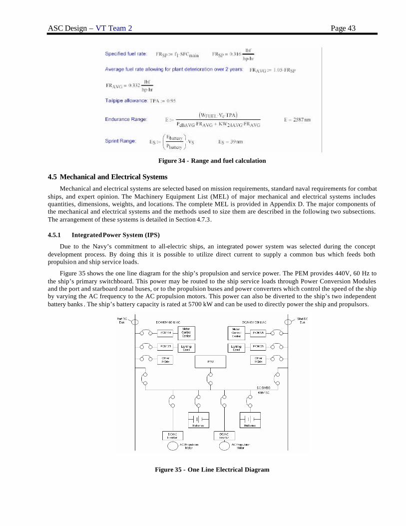
ASC Design – VT Team 2 Page 43
Figure 34 - Range and fuel calculation
4.5 Mechanical and Electrical Systems
Mechanical and electrical systems are selected based on mission requirements, standard naval requirements for combat ships, and expert opinion. The Machinery Equipment List (MEL) of major mechanical and electrical systems includes quantities, dimensions, weights, and locations. The complete MEL is provided in Appendix D. The major components of the mechanical and electrical systems and the methods used to size them are described in the following two subsections. The arrangement of these systems is detailed in Section 4.7.3.
4.5.1 Integrated Power System (IPS)
Due to the Navy’s commitment to all-electric ships, an integrated power system was selected during the concept development process. By doing this it is possible to utilize direct current to supply a common bus which feeds both propulsion and ship service loads.
Figure 35 shows the one line diagram for the ship’s propulsion and service power. The PEM provides 440V, 60 Hz to the ship’s primary switchboard. This power may be routed to the ship service loads through Power Conversion Modules and the port and starboard zonal buses, or to the propulsion buses and power converters which control the speed of the ship by varying the AC frequency to the AC propulsion motors. This power can also be diverted to the ship’s two independent battery banks . The ship’s battery capacity is rated at 5700 kW and can be used to directly power the ship and propulsors.
Figure 35 - One Line Electrical Diagram

ASC Design – VT Team 2 Page 44
4.5.2 Service and Auxiliary Systems
Tanks for lube oil, fuel oil and waste oil are sized based on requirements for the Ship Synthesis model. Equipment capacity and size are based on similar ships.
Potable water for the submarine will be produced using a Reverse Osmosis Distiller. These systems work by heating seawater and pushing it through a series of membranes that both remove the salt from the water as well as remove any other impurities. The resulting water’s purity is equal to that of distilled water. To maximize efficiency, the PEM Fuel Cells could heat the seawater before it enters the unit.
Environmental control is provided by the submarine fan room located beneath the mast. This includes an induction inlet which can be used to ventilate hull exhaust. This system also includes a CO2 scrubber and CO2/H2 burner.
The submarine also emp loys a high pressure air compressor for filling and emptying the main ballast tanks. This is used in conjunction with the main, trim and drain pumps to distribute ballast throughout the submarine as well as in the distiller system to pump in seawater.
4.5.3 Ship Service Electrical Distribution
The submarine’s integrated power system (IPS) is used to power the propulsion system, provide ship service power, as well as charge the batteries. Power from the PEM is sent to the main switchboard where it can then be distributed to any of the three areas previously described. Ship service power is first sent to the zonal buses where it is then distributed to the Power Conversion Modules (PCM) where it can be converted from DC to AC or AC to DC as needed. These PCMs provide circuit protection and automatic reconfiguration for their particular area.
4.6 Manning
The unique missions and size of SCRAP require that manning be a considerable factor in the overall design. Taking into account all the constraints and requirements placed on the boat, the crew size for the Littoral Warfare submarine is set at 2 officers, 2 chiefs, and 8 enlisted personnel. The limited manning forces the crew to all be highly trained and experienced sailors. There would be no enlisted under the rank of Petty Officer 2nd Class and the officers would minimally be Lieutenants with at least one sea-tour. The crew would be basically split up, with half dedicated to manning the ER and ensuring that all the mechanical systems were maintained and the other half manning the OC and running the submarine. The 8 SEALs are not permanently embarked, therefore are not considered crew. There is one SEAL officer, and seven enlisted men who make up the one embarked SEAL platoon.
Table 27 - Manning summary
Crew Member QTY Rank Duty
CO 1 O-4 All Command Duties
XO 1 O-3 OOD, Engineering Officer, Weapons Officer, Dive, and Navigation Officer
Chiefs 2 E-(6-7) Chief of the Boat, Dive Chief, Fire Control Chief, Engineering Chief
Operational Crew 4 E-(4-5)
Sonarmen, Radiomen, Diver, Boatswains Mate, Electrical Technician, Cook, Yeomen
Engineering Crew 4 E-(4-5)
Machinists Mate, Electricians Mate, Electrical Technician, Diver
4.7 Space and Arrangements
Submarine space and arrangement plans are made in AutoCAD and Rhino. AutoCAD is used for 2-D drawings of the submarine subdivision and arrangement as well as plan views of the inboard and outboard space and arrangement. Rhino is used for constructing and arranging 3-D views of the submarine hull, main ballast tanks, pressure hull, PIM module, main deck arrangements, tank subdivisions, weapon & combat systems module, habitability module, and machinery spaces . To balance the submarine, tank volumes and other associated volumes are calculated in Rhino. As with all submarines, space is extremely limited for the SCRAP design. At the Concept Development stage, when laying out the Machinery Space, Operation and Living Compartment the focus is not on specifically where items should go and how space should be used,

ASC Design – VT Team 2 Page 45
but rather if all of the required systems will fit inside the pressure hull. The hull arrangements are divided into three main sections: Sub-deck, Machinery Space, and Living Compartment.
Figure 36 - Plan view with arrangements
4.7.1 Volume
Baseline space requirements and availability in the ship are determined by the ship synthesis model. Volume parameters output by the model are as follows: PIM, propulsion fuel, potable water, sewage, lube oil, battery, auxiliary tank, and main ballast tank. The submarine is modeled in Rhino, and final volumes are taken from the model. SCRAP has a single deck that is divided into enlisted living quarters, officer living quarters, command, mess, commissary, auxiliary machinery, motor and machinery spaces.
4.7.2 Internal Arrangements
SCRAP’s pressure hull diameter is 13 feet, providing enough space for only a single deck configuration. The main deck height is set 4.1 feet above the baseline, giving an overhead height of 8.9 feet. This deck height is to ensure enough overhead space for the hull structure, piping, ventilation ducting, and wire-ways. Below the main deck, there is a crawl space for tanks, batteries, auxiliary rooms. The arrangement of this space is shown in Figure 37. Under the main deck, Variable Ballast Tanks (VBT) are located in the each corner, total six tanks. VBT tanks provide the trim and list corrections as the loads change within the hull. The VBT affect will be maximized by placing them as far from the longitudinal and transverse centers of gravity. Auxiliary thank 1 and 2 is followed by the three forward trim tanks respectively. These tanks can be used for extra fuel, lube oil, waste oil, and other liquid storage. After Auxiliary tank 1 and 2, water and sewage tanks are located. These are directly under the galley and head. Conventional lead acid batteries are used in SCRAP, which are heavier than other compartment sections. Therefore the batteries are located in the center bottom of the submarine to keep the vertical gravity low. They are placed along the longitudinal sides of the PIM module. Diesel fuel tanks are followed by battery storage space in the stern direction. Auxiliary tank 3 is placed after the diesel fuel tanks. This tank can be used for oxygen storage or extra fuel storage.
Table 28 - SCRAP tankage volumes
Tank Capacity (ft3) Vwrt 81
V trim fwd 225 V trim aft 271
VAux1 660 VAux2 660 VAux3 1187

ASC Design – VT Team 2 Page 46
V2fuel 1251 Vlo 45.9037587
Vwater 221 V air flask 262
V2ox 961.5 Vsew 56.577647
Figure 37 - Under-deck arrangement
Figure 38 - SCRAP tankage subdivisions
4.7.3 Machinery Room Arrangements
The machinery space is designed to suit the PEM propulsion system and its associated subsystems. This configuration has been implemented by foreign navies on other non-nuclear boats. Since SCRAP uses dual shrouded propellers, identical sets of machinery items and arrangements exist for port and starboard propulsors . Tentative machinery items are as follows: trim and drain pump, reverse osmosis distiller, high pressure air compressor, seawater cooling pump, main hydraulic pumps, freshwater pump, hydraulic pressure accumulator, trim manifold, induction mast inlet, induction and ventilation fans, LP blower, CO2 scrubber, CO/H2 burner, PEM, DC main switchboard, propulsion DC/AC inverters/controllers, and oxygen tanks.
SCRAP implements traditional AC electric motors to drive its propulsors . The primary source of power is the 250kW PEM fuel cell. In this arrangement, there is control equipment consisting of switches, resistance units, and protective devices designed to permit flexibility of control.
The high pressure air compressor, main hydraulic pumps, freshwater pumps, and hydraulic pressure accumulator are located in the auxiliary machinery room space. The air compressor provides the pressurized air for filling and emptying the MBTs as well as other ship systems. This compressor will be a RIX 5R5 system. The 5R5 is an oil free, water-cooled compressor that can handle up to four different gasses and can reach a maximum pressure of 5000 psig. The system uses a screw style compressor stage that virtually eliminates all vibration, therefore decreasing the submarine’s overall acoustic signature.

SSLW-SCRAP Design – VT Team 4 Page 47
A reverse osmosis distiller (ROD) is used to produce potable water for the submarine. An ROS system works by heating seawater and pushing it through a series of membranes that remove salt as well as any other impurities from the water. The resulting water’s purity is the same as of distilled water. In addition to crew health and comfort needs, large amounts of fresh water are needed by Special Forces operators to keep their dive gear and other equipment clean.
The fan room is located vertically under the sail to ensure prompt ventilation in case of an inboard fire breakout. Induction mast inlet, induction and ventilation fans, LP blower, CO2 scrubber, and the CO/H2 burner are located in the fan room.
4.7.4 Living Arrangements
The unique missions and size of SCRAP requires that manning be a considerable factor in the overall design. Taking into account all the constraints and requirements placed on the boat, the crew size for the submarine is set at 3 officers and 1 SEAL officer, 9 enlisted personnel and 7 SEAL enlisted.
Figure 39 - SCRAP living arrangements
Figure 40 - SCRAP living and operation arrangements

SSLW-SCRAP Design – VT Team 4 Page 48
Table 29 - Accomodation space summary
Item Accommodation Quality
Per Space Number of Spaces
Area Each Total Area
Officer 4 4 1 58.51 58.51 Enlisted 16 16 1 158.05 158.05
Officer &Enlisted Sanitary
20 20 1 262.54 262.54
Total 3 479.1
4.7.5 External Arrangements
At this point in the design, the only external arrangements for SCRAP are the PIM module and torpedo tubes. The PIM module is located in the center of the pressure hull, but is independent from the pressure hull and can only be accessed from the outside. PIM hatches will be placed on the top and bottom surface of the hull area exterior to the PIM module space. This allows flexible mission packages and special forces stowage. In the bow section of the submarine, there are total four torpedo tubes penetrating the hull by way of an inboard torpedo access room each holding one torpedo. Inboard stackup length is not available to support internal reloading of these tubes.
Also of note is SCRAP’s use of an “x-stern” control plane configuration. This configuration allows better control on the surface than a cruciform stern, and better maneuverability at speed.
Figure 41 - SCRAP external arrangements
4.8 Weights and Loading
4.8.1 Weights
Ship weights are grouped by SWBS. Where possible, weights were taken from manufacturer information. The pressure hull weight came from the MAESTRO model. Several weights were parametrically modeled from the KAPPA 3 digit weight report. Weight values were taken from the baseline ship synthesis model when there was no other method of estimating them available. Centers are estimated from the general arrangements. A summary of lightship weights and centers of gravity by SWBS group is listed in Table 30.
Table 30 - Lightship Weight Summary SWBS Group Weight (lton) VCG (ft-Abv BL) LCG (ft-Aft FP)
100 564.25 72.10 6.14 200 635.91 102.22 5.40 300 28.55 83.04 7.32 400 29.58 56.39 4.40

SSLW-SCRAP Design – VT Team 4 Page 49
SWBS Group Weight (lton) VCG (ft-Abv BL) LCG (ft-Aft FP) 500 90.26 81.64 7.25 600 58.07 43.31 4.15 700 16.47 29.40 6.55 800 7.82 69.07 7.31
Lightship 1430.92 84.30 5.80
4.8.2 Loading Conditions
Five operating conditions were considered for SCRAP: a normal condition, a light condition, a heavy condition, a heavy forward condition and a heavy aft condition. These are the standard conditions that need to be considered for investigating submarine submerged stability. A stability polygon which shows the ability of the submarine’s trim and auxiliary tanks to return the vessel to neutral weight and trim while submerged was plotted. The operating conditions were plotted on the stability polygon to make sure that the vessel is indeed stable at all load conditions. A summary of the load conditions is provided in Table 31. The stability polygon is shown in Figure 42.
Table 31 - Load condition summary
Req’d Wt
(lton) Req’d Longitudinal
Moment
Normal Condition -969 -5503
Light -960 -5523
Heavy -976 -5479
Stability Polygon
NormalLightHeavy
-1200.00
-1000.00
-800.00
-600.00
-400.00
-200.00
0.00
200.00
-6000.00 -5000.00 -4000.00 -3000.00 -2000.00 -1000.00 0.00 1000.00
Imparted Moment, Lton-ft
Ad
ded
Wei
gh
t, L
ton
s
Figure 42 - Stability polygon
4.9 Hydrostatics and Stability
4.9.1 Intact Stability
SCRAP benefits from the inherent stability of the catamaran hullform. On the surface, it has a GM of nearly five feet, and submerged it has a BG of one foot. Both of these values are quite large for a small submarine, and SCRAP may even be too stable, leading to an unpleasant environment for the sailors on board. Submarine designs often suffer from stability problems, and SCRAP is likely no different.

SSLW-SCRAP Design – VT Team 4 Page 50
4.9.2 Damaged Stability
SCRAP is at a considerable disadvantage in the area of damaged stability. The low envelope volume and lack of structure to create watertight subdivisions indicate that the design would face catastrophic stability problems if flooded. Additionally, with the lack of the wealth of backup systems seen on nuclear submarines, a casualty to vital pieces of equipment would likely force the abandonment of the ship. As this design is not designed for strike or combat missions, the need for small size and a covert nature outweigh the desire for resilience to damage.
4.10 Seakeeping, Maneuvering, and Control
Submarine seakeeping consists mainly of developing an operating envelope for surfaced operation. If seas develop an unsafe or undesirable operating condition for SCRAP, the crew will dive the boat to a safe depth. Given SCRAP’s significant surfaced stability, behavior in light to moderate seas should be acceptable. At depth, the boat will still be subject to wave action from the surface, especially in littoral waters. As on the surface, SCRAP’s large GB will provide excellent stability in turbid water.
SCRAP would incur extra research spending, as the maneuvering and dynamic characteristics of catamaran are not well known. Due to the use of the “x-stern” control surface configuration, some sort of computer control system would need to be employed to translate operator inputs to appropriate fin deflections as well as to damp any dynamic instability due to the unorthodox hullform.
4.11 Cost and Risk Analysis
During the initial optimization, the ship synthesis model was programmed to estimate cost and the risk associated with the design parameters that is considers. From this information, a baseline cost and risk assessment was developed, and updated as the design matured though the first iteration of the design spiral.
4.11.1 Cost and Producibility
The cost of SSLW is estimated as a lifecycle cost, based on the diagram shown in Figure 43.
Total LCC
Investment R&DResidual
Value
Operations and Support
(O&S)
Personnel Operations Maintenance EnergyReplenishment
SparesMajor Repair and Overhaul
Ship Acquisition
Shore-Based Support
Shore-Based Supply
Design and Development
Test and Evaluation
Figure 43 - Lifecycle cost breakdown for SSLW
The investment in research and development of the catamaran concept hull will be significantly more than a conventional cylindrical hull of the same displacement due to the design’s relative youth. Extensive testing will be necessary to ensure the safety and performance of the design. Ship acquisition costs simply for vessel construction will be approximately $195.6M. The shore and fleet based support structure for rearming and refueling, as well as underway replenishment of a new class of submarine will also warrant further study as the design matures. These studies will include investigating the merits of Sea Basing or deployment from a mother ship, such as an LHD-class ship with a well deck or moon pool. Operational support costs will be much the same as a conventional submarine design with a crew of 20. The NR-1 research submarine was studied to form a baseline operations and support model for the SSLW, as it is a small special needs submarine. The overall lifecycle cost of the SSLW is estimated to be $369M.

SSLW-SCRAP Design – VT Team 4 Page 51
4.11.2 Risk Analysis
As with any new ship design, a certain amount of risk is included with the development of new systems and technologies. These risks were assessed by assigning a value to the likelihood of the risk event to occur, and the level of impact that the risk event would have on the boat. This data was fed into the optimization program, which developed an Overall Measure of Risk, or OMOR. The SSLW concept chosen as the baseline for this design was given an OMOR of .4436, which is classified as “medium”. This higher level of risk is attributed mainly to the use of a PEM and Reformer as the primary means of powering the boat, the use of externally encapsulated torpedoes, and the innovative catamaran hullform design. However, the boat’s risk is mitigated through the use of extremely reliable and field-tested lead acid batteries.
5 Conclusions and Future Work
5.1 Assessment
Much work was undertaken to produce a design from the baseline characteristics specified by the optimizer. Work carried out in Concept Development has shown that the optimizer produced some optimistic baseline numbers and some conservative. With the added surface area of a catamaran hullform, SCRAP cannot reach its intended sprint speed of 21.6 knots. This additionally affects the sprint range. The endurance range calculated in the propulsion section of this document proved to be much higher than expect, and is almost enough for a transit of the Atlantic Ocean. Structural adequacy will most likely allow for a diving depth beyond 300 feet.
Overall, the final concept baseline shows a close agreement with the specifications of the ORD as well as the original concept baseline, as seen in Table 32.
Table 32 - Compliance with Operational Requirements
Technical Performance Measure ORD TPM (Threshold)
Original Goal
Concept BL Final Concept BL
Number of PIMs 1 1 1 1
Endurance range (nm) 1113 500 2590 2590
Sprint range (nm) 43.6 50 40 40
Stores duration (days) 26 30 29 29
Diving depth (ft) 290 300 290 300+
Sustained speed Vs (knt) 21.6 25 21.6 20
Crew size (excluding SPW or mission techs)
13 10 13 13
SPW/Mission techs 8 8 8 8
5.2 Future Work
There is still much work to be accomplished on the SCRAP concept baseline. § Perform analyses or research to discover SCRAP’s dynamic stability and maneuverability as well as
seakeeping characteristics. Are there any issues maneuvering at speed? Can they be corrected through computer control or design alteration?
§ Conduct further research into submarine propulsors. The 4-bladed B-series propulsor used here is an acceptable first guess, but using high-skew props with 7 blades or more may be more efficient, allowing higher sprint speeds and longer endurance ranges.
§ Revise weight and volume estimates. SCRAP in its current form suffers from a lack of buoyancy. Can additional tankage or other volumes balance the design? Achieve a more accurate weight estimate.
§ Review arrangements and tankages. Is the design maximizing useable space? Can it be more functional? Are there issues with arrangements, especially in regards to fuel cell/reformer and machinery arrangements? Can the fuel cell be scaled to produce more power (300kW+)?
§ Long term: Investigate mother-ship/Sea Base arrangements available to SCRAP. Can it utilize an LHD-type ship with a well deck/moon pool? What other options (near term and long term) are available for SCRAP’s transit-to-station?

SSLW-SCRAP Design – VT Team 4 Page 52
5.3 Conclusions
As previously listed, there are still many concerns with the SCRAP design in its current state. However, the research involved in addressing these concerns is beginning at many universities and US Navy labs. Fuel cell power is currently deployed by foreign navies, and many other systems are available as off-the-shelf commercial solutions.
The need for a submarine design with SCRAP’s capabilities cannot be ignored. Featuring a propulsion plant with fewer moving parts than a nuclear reactor and the size to operate in the enemy’s rivers and harbors, SCRAP would serve to revolutionize the United States warfighting system by providing quick and quiet transit for special forces teams, reconnaissance packages, AUVs, and even limited-range strike weaponry. Modern concerns over piloting nuclear vessels close to shore in hostile waters would be immaterial, as would qualms with placing hundreds of lives in harms way.
SCRAP provides a more capable operator delivery platform than current technologies such as DSRV or ASDS, and does so at a fraction of the cost of the new Virginia-class submarines. This boat is quiet, relatively quick, and has the provisions for extended independent operation. SCRAP can deploy multiple modular flexible mission packages that are easily and quickly loaded and can be configured to extend SCRAP’s mission capabilities or solve entirely new problems. With only a few knowledge barriers to hurdle, SCRAP is highly effective with minimal risk, and is the ideal solution to the new model of covert warfare.
Submersible Covert Reconnaissance – Alternative Platform: Changing the way freedom is delivered.

SSLW-SCRAP Design – VT Team 4 Page 53
References 1. Brown, A.J., “Ship Design Notes”, Virginia Tech AOE Department, 2004. 2. Comstock, John P., ed. Principles of Naval Architecture, New Jersey: Society of Naval Architects and Marine
Engineers (SNAME), 1967. 3. Gilmer, Thomas C. and Johnson, Bruce. Introduction to Naval Architecture. Naval Institute Press, Annapolis,
MD, 1982 4. Harrington, Roy L, ed. Marine Engineering. New Jersey: Society of Naval Architects and Marine Engineers
(SNAME), 1992. 5. U.S. NavyFact File. 2004. U.S. Navy Home Page. http://www.chinfo.navy.mil/navpalib/factfile/ffiletop.html

SSLW-SCRAP Design – VT Team 4 Page 54
Appendix A – SSLW Mission Need Statement (MNS)
MISSION NEED STATEMENT
FOR
Littoral Warfare Submarine – SSLW 1. DEFENSE PLANNING GUIDANCE ELEMENT.
With the collapse of the Cold War, the Department of the Navy developed a new policy, called "From the Sea". This document outlines a significant change in priorities from a "Blue Water Navy fighting a traditional Super Power". The rapidly changing global political climate prompted the Department of the Navy to publish a revised policy, "Forward from the Sea", in December 1994. This policy set forth a directive for the Navy and Marine Corps team to have faster and more conflict specific responses. Most recently, the Quadrennial Defense Review Report and the Department of the Navy’s new whitepaper, “Naval Transformational Roadmap,” provide additional unclassified guidance and clarification on current DOD and USN defense policies and priorities.
The Quadrennial Defense Review Report identifies six critical US military operational goals. These are: protecting critical bases of operations; assuring information systems; protecting and sustaining US forces while defeating denial threats; denying enemy sanctuary by persistent surveillance, tracking and rapid engagement; enhancing space systems; and leveraging information technology.
The Naval “Transformational Roadmap” provides the US Navy’s plan to support these goals including nine necessary warfighting capabilities in the areas of Sea Strike – strategic agility, maneuverability, ISR, time -sensitive strikes; Sea Shield – project defense around allies, exploit control of seas, littoral sea control, counter threats; and Sea Base – accelerated deployment & employment time, enhanced seaborne positioning of joint assets.
This Mission Need Statement specifically addresses six of these warfighting capabilities. They are: ISR, time-sensitive strike, accelerated deployment and employment time, information operations, littoral sea control, and mine countermeasures. While addressing these capabilities, there is also a need to reduce cost and minimize personnel in harms way. 2. MISSION AND THREAT ANALYSIS.
a. Threat.
(1) Adversaries may range from Super Powers to numerous regional powers, and as such the US requires increased flexibility to counter a variety of threat scenarios that may rapidly develop. There are two distinct classes of threats to US national security interests:
(a) Threats from nations with a major military capability, or the demonstrated interest in acquiring such a capability, i.e. China, India, Russia, and North Korea. Specific weapons systems that could be encountered include coastal patrol craft, airborne sub detecting hardware, scuba divers, and other submarines.
(b) Threats from smaller nations who support, promote, and perpetrate activities which cause regional instabilities detrimental to international security and/or have the potential for development of nuclear weapons, .i.e. Iraq and Iran. Specific weapon systems include diesel/electric submarines, land-based air assets, and small littoral attack vessels.
(2) Since many potentially unstable nations are located on or near geographically constrained bodies of water, the tactical picture will be on a smaller scale relative to open ocean warfare. Threats in such an environment include: (1) technologically advanced weapons - land-based attack aircraft, fast coastal patrol gunboats armed with guns and torpedoes, and diesel-electric submarines; and (2) unsophisticated and inexpensive passive weapons – mines and anti-submarine nets. Many encounters may occur in shallow water, which increases the difficulty of detecting and successfully prosecuting targets using standard sonar equipment. Platforms chosen to support and replace current assets must have the capability to dominate all aspects of the littoral environment.

SSLW-SCRAP Design – VT Team 4 Page 55
b. Required Mission Capabilities.
Enhance our ability to provide the following capabilities specified in the Defense Planning Guidance:
(1) Extract vital enemy information through covert ISR operations from near-shore locations.
(2) Insert, extract, and support U.S. Special Forces by covert means to shore targets as close as possible.
(3) Conduct precise and timely ASUW/ASW strikes with a stealthy approach and evasion.
(4) Conduct mine countermeasures
(5) Capable of multiple and flexible missions
Given the following significant constraints:
(1) Minimize personnel in harms way. (2) Reduce cost.
c. Need.
Current assets supporting these capabilities include: (1) SSN and SSBN submarines with DDS shelters deploying SEALS with the SDV (2) U.S. Special Forces high speed insertion craft or air dropped
(3) Space-based reconnaissance
(4) Surface Vessels
These assets are costly and/or put significant numbers of personnel in harms way. Their cost does not allow for sufficient worldwide coverage of all potential regions of conflict and sufficient penetration of the littoral zone to carry out the prescribed missions. None of the current assets have the facilities necessary to support continuous ISR operations and Special Forces readiness for time-sensitive missions. The Special Forces have extremely difficult missions that require a level of preparation and pinpoint insertion that none of the assets offer.
There is a mission need for a SSLW support and delivery system or platform to provide the mission capabilities specified in paragraph (b.) above. This transformational system must be developed with highly focused mission goals to attain the stealth ability required for littoral operations. 3. NON-MATERIAL ALTERNATIVES.
a. Change the US role in the world by reducing international involvement. b. Increase reliance on non-military assets and options to enhance the US performance of the missions
identified above while requiring a smaller inventory of naval forces.
c. Increased use of SSNs and SSGNs fitting with DDS and capable of deploying Special Forces. d. Increasing production of the ASDS, which is coming online FY2003. e. Increased use of current Special Forces insertion methods via air drop or high speed surface vessels.
4. POTENTIAL MATERIAL ALTERNATIVES.
a. Modify the current ASDS or DSRV design to increase mission time and overall mission effectiveness.
b. Modify existing SSN submarines for shallow water operation.
c. Create a new class of technologically advanced, mid-sized littoral warfare submarine with the ability for covert warfare.
5. CONSTRAINTS
a. The platform must be non-nuclear powered, too keep down cost and manning. b. The submarine must have an on-station, independent endurance of at least 30 days.
c. The submarine must have a crush depth no less then 300 feet. d. The platform must be highly producible, minimal time from design to production. e. The submarine must be fast and covert.
f. The submarine must be capable of upgrades, flexible and multiple missions.

SSLW-SCRAP Design – VT Team 4 Page 56
Appendix B – SSLW Acquisition Decision Memorandum (ADM)
1 September 2004 From: Virginia Tech Naval Acquisition Executive To: SSLW(X) Design Team Subject: ACQUISITION DECISION MEMORANDUM FOR A LITTORAL WARFARE
SUBMARINE (SSLW(X)) Ref: (a) SSLW(X) Mission Need Statement 1. This memorandum authorizes concept exploration for a Littoral Warfare Submarine, as proposed to the Virginia Tech Naval Acquisition Board in Reference (a).
2. Concept exploration is authorized for SSLW(X) consistent with the mission requirements and constraints specified in Reference (a). SSLW(X) will operate from a mother ship, and deploy into restrictive littoral regions. It will utilize passive stealth qualities, relatively small size, and high maneuverability to routinely operate closer to enemy shores than previous US submarines. This will allow SSLW(X) to deploy Special Forces closer to shore, limit their exposure to cold water, provide an offshore base and avoid possible detection. The SSLW(X) will also perform harbor penetration missions to gain detailed ISR and perform MCM needed for battles of the future. UUVs will extend the SSLW(X) mission capabilities to obtain more detailed ISR and perform limited mine hunting operations.
3. Exit Criteria. SSLW(X) shall have a minimum endurance range of 1500 nm at 10 knots, a minimum sustained (sprint) speed of 15 knots, a minimum sprint range of 25 nm, a minimum operating depth of 250 feet, and a service life of 30 years. It shall be completely air- independent. It is expected that 10 ships of this type will be built with IOC in 2015. Average follow-ship acquisition cost shall not exceed $500M. Manning shall not exceed 35 personnel. A.J. Brown VT Acquisition Executive
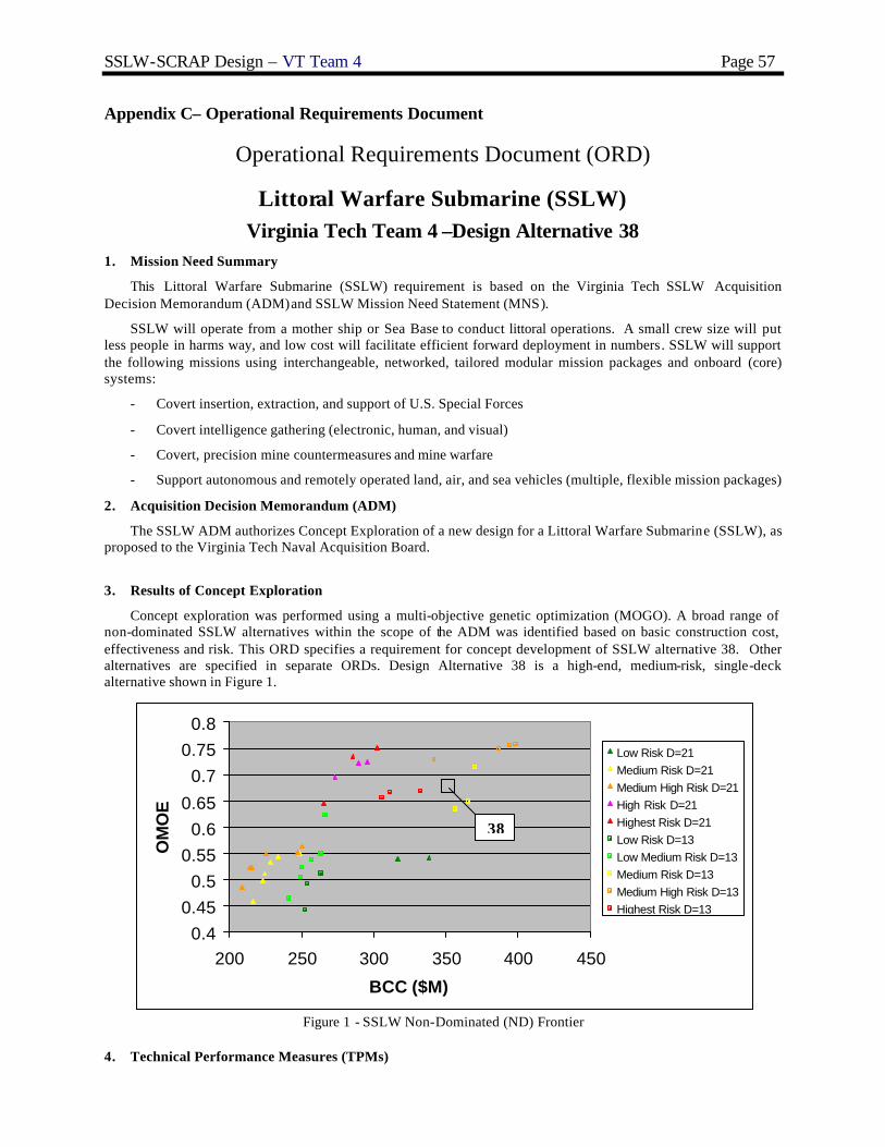
SSLW-SCRAP Design – VT Team 4 Page 57
Appendix C– Operational Requirements Document
Operational Requirements Document (ORD)
Littoral Warfare Submarine (SSLW)
Virginia Tech Team 4 –Design Alternative 38 1. Mission Need Summary
This Littoral Warfare Submarine (SSLW) requirement is based on the Virginia Tech SSLW Acquisition Decision Memorandum (ADM) and SSLW Mission Need Statement (MNS).
SSLW will operate from a mother ship or Sea Base to conduct littoral operations. A small crew size will put less people in harms way, and low cost will facilitate efficient forward deployment in numbers. SSLW will support the following missions using interchangeable, networked, tailored modular mission packages and onboard (core) systems:
- Covert insertion, extraction, and support of U.S. Special Forces
- Covert intelligence gathering (electronic, human, and visual)
- Covert, precision mine countermeasures and mine warfare
- Support autonomous and remotely operated land, air, and sea vehicles (multiple, flexible mission packages)
2. Acquisition Decision Memorandum (ADM)
The SSLW ADM authorizes Concept Exploration of a new design for a Littoral Warfare Submarine (SSLW), as proposed to the Virginia Tech Naval Acquisition Board.
3. Results of Concept Exploration
Concept exploration was performed using a multi-objective genetic optimization (MOGO). A broad range of non-dominated SSLW alternatives within the scope of the ADM was identified based on basic construction cost, effectiveness and risk. This ORD specifies a requirement for concept development of SSLW alternative 38. Other alternatives are specified in separate ORDs. Design Alternative 38 is a high-end, medium-risk, single-deck alternative shown in Figure 1.
0.40.45
0.50.55
0.60.65
0.70.75
0.8
200 250 300 350 400 450
BCC ($M)
OM
OE
Low Risk D=21Medium Risk D=21Medium High Risk D=21High Risk D=21Highest Risk D=21Low Risk D=13Low Medium Risk D=13Medium Risk D=13Medium High Risk D=13Highest Risk D=13
Figure 1 - SSLW Non-Dominated (ND) Frontier
4. Technical Performance Measures (TPMs)
38

SSLW-SCRAP Design – VT Team 4 Page 58
TPM Threshold Number of PIMs 1
Endurance range (nm) 1113
Sprint range (nm) 43.6
Stores duration (days) 26
Diving Depth (ft) 290
Sustained Speed Vs (knt) 21.6
Crew size (excluding SPW or mission techs) 13
SPW or Mission Techs 8
5. Program Requirements
Program Requirement Threshold
Basic Cost of Construction ($M) 375
6. Baseline Ship Characteristics (HI2 Alternative)
Concept development will begin with the following baseline design:
Hullform Catamaran with partial connecting hull
Hull Material Steel
∆ (lton) (Wnsc) 1282
LOA (ft) 169
Beam (ft) 28
Depth (ft) 13
W1 (lton) 309.4
W2 (lton) 200.9
W3 (lton) 36.56
W4 (lton) 17.5
W5 (lton) 53.5
W6 (lton) 43.6
W7 (lton) 3.6
Wcondition A -1 (lton) 665.1
Lead Ballast (lton) 51.9
Wcondition A 716.9
BG (ft) 1.1
Propulsion system 250kW PEM Fuel Cell w/ Reformer IPS
Core Combat Systems
Passive ranging sonar, flank array sonar, integrated bow array sonar, 2 inboard torpedo tubes, 6 external torpedoes, countermeasure launchers, UAV mast launch, Shrike mast, MMA, mine avoidance sonar, degaussing, 9 man lock-out trunk
Number of Payload Modules 1
7. Other Design Requirements, Constraints and Margins
KG margin (m) 1.0
Propulsion power margin (endurance) 10 %
Propulsion power margin (sustained speed) 25% (0.8 MCR)
Electrical margins 5%
Weight margin (design and service) 10% 8. Special Design Considerations and Standards
Concept development shall consider and evaluate the following specific areas and features: • Ship impact of equipping SSLW with a degaussing system.

SSLW-SCRAP Design – VT Team 4 Page 59
• Propulsion plant options shall consider the need for reduced acoustic and infrared signatures while addressing required speed and endurance.
• Reduced manning and maintenance factors shall be considered to minimize total ownership cost
The following standards shall be used as design “guidance”: § SUBSAFE § Endurance Fuel: DDS 200-1 § Electric Load Analysis: DDS 310-1
Use the following cost and life cycle assumptions: § Ship service life = LS = 15 years § Base year = 2010 § IOC = 2015 § Total ship acquisition = NS = 15 ships § Production rate = RP = 2 per year

SSLW-SCRAP Design – VT Team 4 Page 60
Appendix D – Machinery Equipment List
Item Equipment Name Quantity Dimensions (LxWxH)
1 Trim and Drain Pumps 2 2x1x1 ft 2 Reverse Osmosis Distiller 2 4x4x4 ft 3 High Pressure Air Compressor 1 3x3x3 ft 4 Seawater Cooling Pump 2 2x1x1 ft 5 Main Hydraulic Pump 2 2x1x1 ft 6 Freshwater Pump 2 1x1x1 ft 7 Hydraulic Pressure Accumulator 2 Cylinder: D = 1 ft, L = 2 ft 8 Trim Manifold 2 2x1x1 ft 9 Induction Mast Inlet 1 Cylinder: D = 1ft 10 Induction and Ventilation Fan 2 2x1x1 ft 11 Low Pressure Blower 1 3x3x3 ft 12 CO2 Scrubber 2 1x1x2 ft 13 CO2/H2 Burner 2 1x1x2 ft 14 PEM 1 9x4x9 ft 15 DC Main Switchboard 1 6x1x6 ft 16 Propulsion Motor 2 7.75x7.75x6.67 ft 17 Propulsion DC/AC Inverter 2 2x2x1 ft 18 Power Conversion Module 4 1x1x3 ft 19 Motor Control Center 2 1x1x3 ft 20 Lighting Load Panel 2 1x1x3 ft

SSLW-SCRAP Design – VT Team 4 Page 61
Appendix E - Weights and Centers
The weight spreadsheet is maintained in a large set of Microsoft Excel worksheets. They can be found posted on the Team 4 Blackboard group page.
SSLW-SCRAP Design – VT Team 4 Page 62
Appendix F – SSCS Space Summary
Space and volume numbers are incomplete currently. This will be updated.

SSLW-SCRAP Design – VT Team 4 Page 63
Appendix G - MathCAD Propulsion Model
The propulsion calculations can be found in Team 4’s group page on Blackboard as “PropCalc.pdf”.