Lithium Isotope Enrichment: Feasible Domestic Enrichment...
49
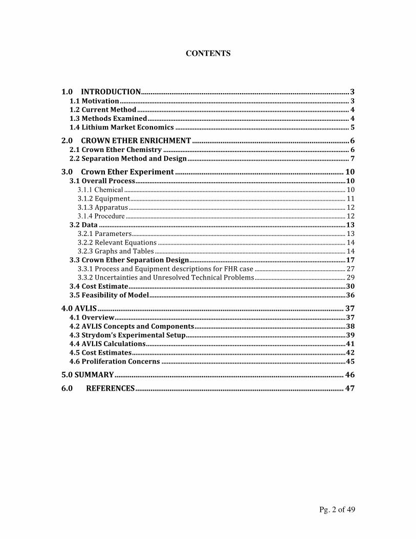
Pg. 1 of 49 Lithium Isotope Enrichment: Feasible Domestic Enrichment Alternatives Tim Ault Krzysztof Brozek Lingchen Fan Micah Folsom Joshua Kim Joshua Zeismer Department of Nuclear Engineering University of California, Berkeley Report UCBTH-12-005 5 May 2012 ABSTRACT In response to the United States’ dire demand for Li-7, a study was conducted to explore and determine stable and economically viable domestic sources. Two alternative methods to mercury-based separation were investigated: crown-ether enrichment and atomic vapor laser isotope separation (AVLIS). Further experimentation is recommended to determine optimal parameters for a scaled-up mixer-settler system using crown ethers as reagents. An economic analysis of the mixer-settler system indicates that crown ethers may be an economically competitive option if used for large-scale production. AVLIS analysis indicates that high quality product may be obtainable in relatively few stages. AVLIS appears quite affordable but may be difficult to produce on a larger scale. Comparing the two options, AVLIS appears to be the better choice for meeting current U.S. pressurized water reactor (PWR) demands, while a mixer-settler crown ether system seems more viable if a fluoride salt-cooled high temperature reactor (FHR) market emerges. Given the strategic importance of continued and reliable operation of U.S. PWRs, it is recommended that the American utility industry encourage the development of a domestic supply of enriched Li-7 by offering to enter into long-term procurement contracts with a U.S.-based supplier and to encourage development of one or both of the enrichment methods described here.
Transcript of Lithium Isotope Enrichment: Feasible Domestic Enrichment...
Pg. 1 of 49
Lithium Isotope Enrichment: Feasible Domestic Enrichment Alternatives
Tim Ault Krzysztof Brozek
Lingchen Fan Micah Folsom
Joshua Kim Joshua Zeismer
Department of Nuclear Engineering University of California, Berkeley
Report UCBTH-12-005
5 May 2012
ABSTRACT
In response to the United States’ dire demand for Li-7, a study was conducted to explore and determine stable and economically viable domestic sources. Two alternative methods to mercury-based separation were investigated: crown-ether enrichment and atomic vapor laser isotope separation (AVLIS). Further experimentation is recommended to determine optimal parameters for a scaled-up mixer-settler system using crown ethers as reagents. An economic analysis of the mixer-settler system indicates that crown ethers may be an economically competitive option if used for large-scale production. AVLIS analysis indicates that high quality product may be obtainable in relatively few stages. AVLIS appears quite affordable but may be difficult to produce on a larger scale. Comparing the two options, AVLIS appears to be the better choice for meeting current U.S. pressurized water reactor (PWR) demands, while a mixer-settler crown ether system seems more viable if a fluoride salt-cooled high temperature reactor (FHR) market emerges. Given the strategic importance of continued and reliable operation of U.S. PWRs, it is recommended that the American utility industry encourage the development of a domestic supply of enriched Li-7 by offering to enter into long-term procurement contracts with a U.S.-based supplier and to encourage development of one or both of the enrichment methods described here.
Pg. 2 of 49
CONTENTS
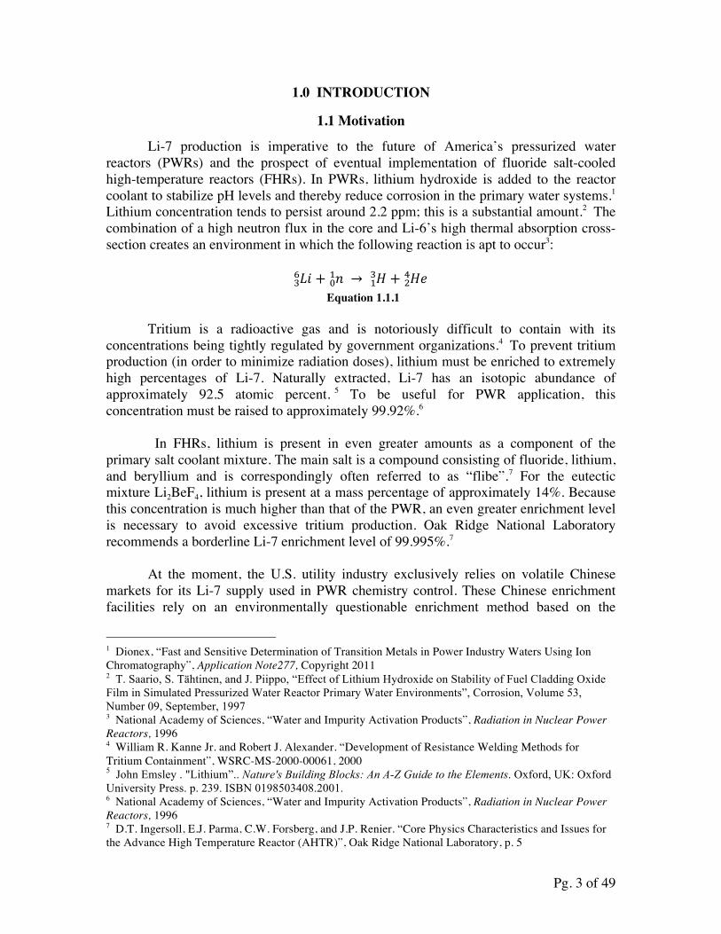
1.0 INTRODUCTION .............................................................................................................. 3 1.1 Motivation .................................................................................................................................... 3 1.2 Current Method .......................................................................................................................... 4 1.3 Methods Examined .................................................................................................................... 4 1.4 Lithium Market Economics .................................................................................................... 5
2.0 CROWN ETHER ENRICHMENT ................................................................................... 6 2.1 Crown Ether Chemistry ........................................................................................................... 6 2.2 Separation Method and Design ............................................................................................. 7
3.0 Crown Ether Experiment ......................................................................................... 10 3.1 Overall Process ......................................................................................................................... 10
3.1.1 Chemical ................................................................................................................................................ 10 3.1.2 Equipment ............................................................................................................................................ 11 3.1.3 Apparatus ............................................................................................................................................. 12 3.1.4 Procedure ............................................................................................................................................... 12
3.2 Data .............................................................................................................................................. 13 3.2.1 Parameters ........................................................................................................................................... 13 3.2.2 Relevant Equations .......................................................................................................................... 14 3.2.3 Graphs and Tables ............................................................................................................................ 14
3.3 Crown Ether Separation Design .......................................................................................... 17 3.3.1 Process and Equipment descriptions for FHR case ........................................................... 27 3.3.2 Uncertainties and Unresolved Technical Problems ........................................................... 29
3.4 Cost Estimate ............................................................................................................................. 30 3.5 Feasibility of Model ................................................................................................................. 36
4.0 AVLIS .................................................................................................................................. 37 4.1 Overview ..................................................................................................................................... 37 4.2 AVLIS Concepts and Components ....................................................................................... 38 4.3 Strydom’s Experimental Setup ............................................................................................ 39 4.4 AVLIS Calculations ................................................................................................................... 41 4.5 Cost Estimates ........................................................................................................................... 42 4.6 Proliferation Concerns .......................................................................................................... 45
5.0 SUMMARY ......................................................................................................................... 46 6.0 REFERENCES .............................................................................................................. 47
Pg. 3 of 49
1.0 INTRODUCTION
1.1 Motivation
Li-7 production is imperative to the future of America’s pressurized water reactors (PWRs) and the prospect of eventual implementation of fluoride salt-cooled high-temperature reactors (FHRs). In PWRs, lithium hydroxide is added to the reactor coolant to stabilize pH levels and thereby reduce corrosion in the primary water systems.1 Lithium concentration tends to persist around 2.2 ppm; this is a substantial amount.2 The combination of a high neutron flux in the core and Li-6’s high thermal absorption cross-section creates an environment in which the following reaction is apt to occur3:
!" !! + !!! → !!! + !" !
! Equation 1.1.1 Tritium is a radioactive gas and is notoriously difficult to contain with its
concentrations being tightly regulated by government organizations.4 To prevent tritium production (in order to minimize radiation doses), lithium must be enriched to extremely high percentages of Li-7. Naturally extracted, Li-7 has an isotopic abundance of approximately 92.5 atomic percent. 5 To be useful for PWR application, this concentration must be raised to approximately 99.92%.6
In FHRs, lithium is present in even greater amounts as a component of the
primary salt coolant mixture. The main salt is a compound consisting of fluoride, lithium, and beryllium and is correspondingly often referred to as “flibe”.7 For the eutectic mixture Li2BeF4, lithium is present at a mass percentage of approximately 14%. Because this concentration is much higher than that of the PWR, an even greater enrichment level is necessary to avoid excessive tritium production. Oak Ridge National Laboratory recommends a borderline Li-7 enrichment level of 99.995%.7
At the moment, the U.S. utility industry exclusively relies on volatile Chinese
markets for its Li-7 supply used in PWR chemistry control. These Chinese enrichment facilities rely on an environmentally questionable enrichment method based on the
1 Dionex, “Fast and Sensitive Determination of Transition Metals in Power Industry Waters Using Ion Chromatography”, Application Note277, Copyright 2011 2 T. Saario, S. Tähtinen, and J. Piippo, “Effect of Lithium Hydroxide on Stability of Fuel Cladding Oxide Film in Simulated Pressurized Water Reactor Primary Water Environments”, Corrosion, Volume 53, Number 09, September, 1997 3 National Academy of Sciences, “Water and Impurity Activation Products”, Radiation in Nuclear Power Reactors, 1996 4 William R. Kanne Jr. and Robert J. Alexander. “Development of Resistance Welding Methods for Tritium Containment”, WSRC-MS-2000-00061, 2000 5 John Emsley . "Lithium”.. Nature's Building Blocks: An A-Z Guide to the Elements. Oxford, UK: Oxford University Press. p. 239. ISBN 0198503408.2001. 6 National Academy of Sciences, “Water and Impurity Activation Products”, Radiation in Nuclear Power Reactors, 1996 7 D.T. Ingersoll, E.J. Parma, C.W. Forsberg, and J.P. Renier. “Core Physics Characteristics and Issues for the Advance High Temperature Reactor (AHTR)”, Oak Ridge National Laboratory, p. 5
Pg. 4 of 49
convenient phase separations offered by mercury. This technique is no longer considered acceptable within the U.S. and any attempt to enter this market is apt to be stifled through undercutting consumer prices by Chinese suppliers. Domestic suppliers would struggle to survive a market environment like this.
Given the importance of reliable access to enriched lithium for continued operation of PWRs and new LWR small modular reactors, it’s recommended that the U.S. utility industry act collectively and offer to enter into long-term procurement contracts with one or more domestic suppliers to encourage the development of a environmentally sustainable domestic lithium enrichment capability. Thankfully, a number of prospective alternative enrichment methods exist, though most have not been developed on a widespread commercial scale. Success with the additional screening activity recommended could promote the demonstration and commercial deployment of one or both of the enrichment methods identified in this report.
1.2 Current Method
China currently employs the COLEX process to enrich lithium, a technology that has changed little since its development in the 1950s and 60s. Mercury is counter-flown against a solution of lithium hydroxide. Oak Ridge researchers found that Li-6 accumulates in the mercury phase, and massive multi-stage processes were developed. Widespread use of this technology, however, has potentially disastrous environmental implications. A significant amount of mercury is required (24 million pounds were used in the U.S.) and there exists many opportunities for leaks into the environment.8 The General Services Administration admits that large quantities of mercury were lost at Oak Ridge to “wastes, spills, and through evaporation”.8 Cleanup remains extremely difficult and expensive both in initial costs and environmentally. Correspondingly, the EPA stopped and prohibited further use of the COLEX process in the U.S., which strengthens China’s near unanimous hold over the market.
1.3 Methods Examined
A number of mercury-free alternatives have been proposed in open literature to enrich Li-7. These include, but are not limited to, ion exchange chromatography, crown and lariat ethers, cryptands, complexation, electro-migration, and electromagnetic separation.9 Methods relying primarily on electromagnetic separations were deemed impractical due to high running costs and constant material replacement, while a number of the chemical methods would require extremely high materials costs.
Consequently, two options emerge as the more practical and each offers its own
appealing characteristics. AVLIS (atomic vapor laser isotope separation) is a fairly well established technology with well-documented properties and results. This technique is already widely known to be effective in isotope separations and was considered for
8 M. Ragheb, Isotopic Separation and Enrichment, University of Illinois Urbana-Champaign Course Materials, 2012. 9 David Holcomb, researcher at Oak Ridge National Laboratory
Pg. 5 of 49
uranium enrichment.10 General Electric has two laser facilities planned for Wilmington, North Carolina: a demonstrative SILEX (separation of isotopes by laser excitation) isotopic laser facility and a commercially ready Hitachi laser facility.11
The second option requires designing a plant utilizing the capacity of crown
ethers to separate lithium isotopes. Initial research indicates a high capacity for separation, although scale-up efforts have thus far been minimal.
1.4 Lithium Market Economics
The current market for all the PWRs in the U.S. is 400 kg of enriched Li-7 per annum.12 In addition, FHRs are designed to use the primary salt, Li2BeF4, which would also be enriched in Li-7. The flibe for FHRs is considered a capital cost, as most of the flibe is reusable (with slight burn-up), thus does not have to be replaced such as the lithium used for chemistry control in a PWR. FHRs require 150-400 metric tons of flibe per GWe capacity, depending on design.13 With lithium being approximately 14% (by mass) of the flibe, FHRs would require approximately 21-56 MT of enriched lithium per 1 GWe capacity. Assuming ten 450 MWe FHRs would be built every year, the demand for enriched lithium for FHR purposes would be 94.5 to 252 MT per year.
If no FHR construction is projected and our market only includes PWRs, then the demand remains 400 kg/yr in the U.S. If FHRs are projected to be built in the U.S., the demand for enriched lithium increases greatly to 21-56 tons per GWe in FHR capacity. In 2010, the estimated price for Chinese enriched Li-7 was $15,000/kg for 99.99% enrichment level.14 Since prices for 99.92% enriched lithium were not found, the price was estimated to be roughly in the $10,000/kg range (taken from the higher enrichment prices). For 400 kg/year demand, this would equate to a revenue of $4 million/year for only the domestic PWRs. For FHRs, the acceptable cost of enriched lithium would be on the order of $500/kg or less. Assuming ten 450-MWe FHRs built per year, the potential annual market value would be between $47 and $126 million, depending on the model of FHR and lithium required, with worldwide revenues projected to be significantly higher.
10 John Pike, “Laser Isotope Separation Uranium Enrichment”, Global Security, ed. 2012. http://www.globalsecurity.org/wmd/intro/u-laser.htm 11 WISE Uranium Project, “Uranium Conversion/Enrichment: Current Issues (USA)”. Ed. 2012.http://www.wise-uranium.org/epusa.html 12 Per F. Peterson, personal communication (email), February 2, 2012 13 Per F. Peterson (email), January 13, 2011 14 Per F. Peterson (email), June 7, 2010
Pg. 6 of 49
2.0 CROWN ETHER ENRICHMENT
2.1 Crown Ether Chemistry
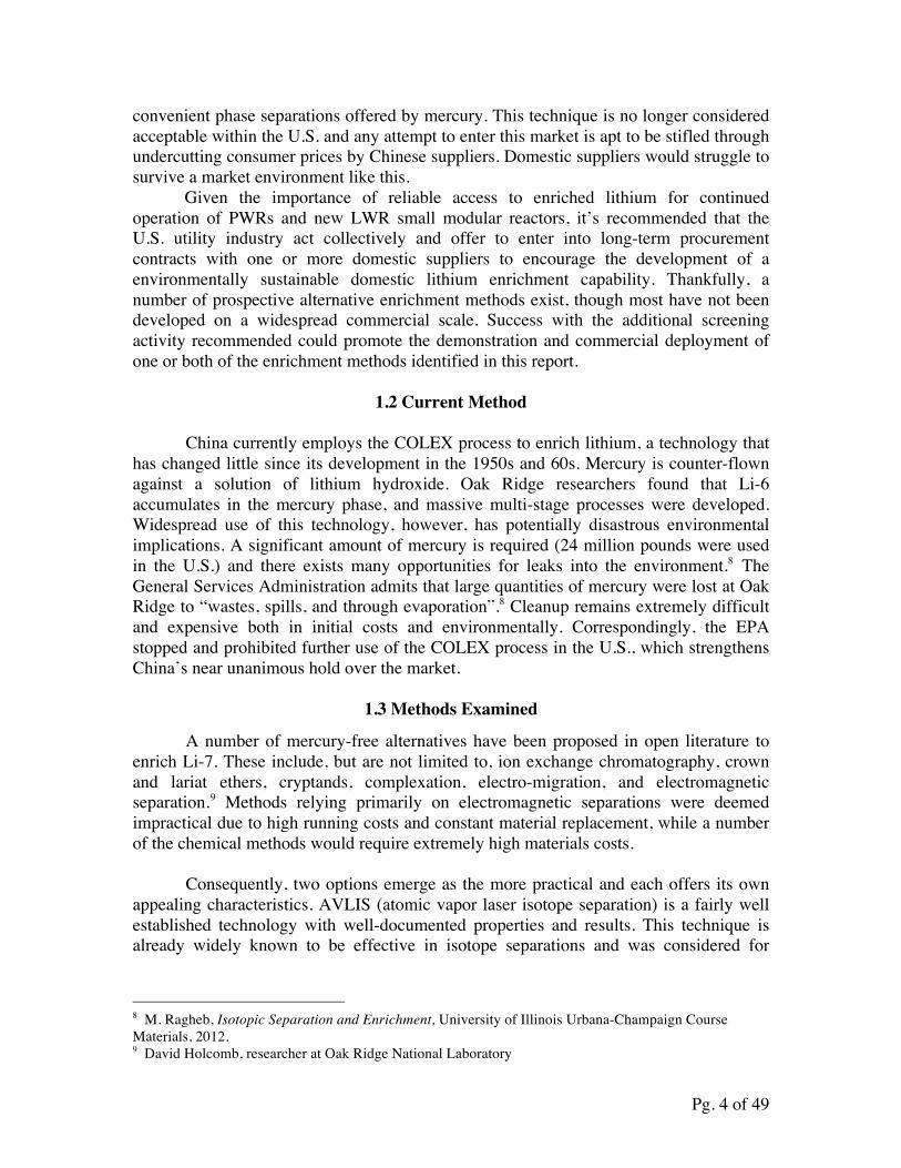
Crown ethers represent one of the most promising alternatives to mercury-based enrichment methods. Certain ether species have ring properties that make them inclined to bond more with specific element isotopes than others. One subset of crown ether separation techniques involves the use of an immobilized resin. This method is already used to produce nitrogen-15 on a small scale.15 In this case, a resin column is immersed in an ammonium salt–methanol mixture and the ammonium with nitrogen-15 is found to preferentially bond in the resin phase, which can then be separated. The setup for such a system resembles the following diagram:
Figure 2.1.1 Experimental Apparatus of Displacement Chromatography16
There are reports that resin-based systems can be developed for Li-7 enrichment as well. One group reported synthesizing a resin column with 15-benzo-crown-5 as the functional group, varying parameters such as column length, temperature and halide type (LiCl, LiBr, LiI).17 They found included values for the separation factor in the report. This parameter indicates the ability of a single-stage to selectively favor one isotope in one of the phases, and can be defined as such.
15 Nagoya University, “Isotopes for the Prosperous Future: Isotope Separation/Production”. 21st Century COE Program, Updated 2007. http://coe.nucl.nagoya-u.ac.jp/Separation01_E.html 16 Nagoya University, Experimental Apparatus of Displacement Chromatography (Diagram), 2007 17 Klaus G. Heumann, “Isotopic Separation in Systems with Crown Ethers and Cryptands”, Organic Chemistry: Topics in Current Chemistry, 1985, Vol. 127, pp. 77-132 (pp. 120-122)
Pg. 7 of 49
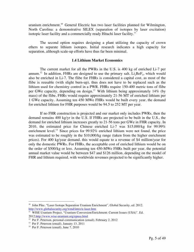
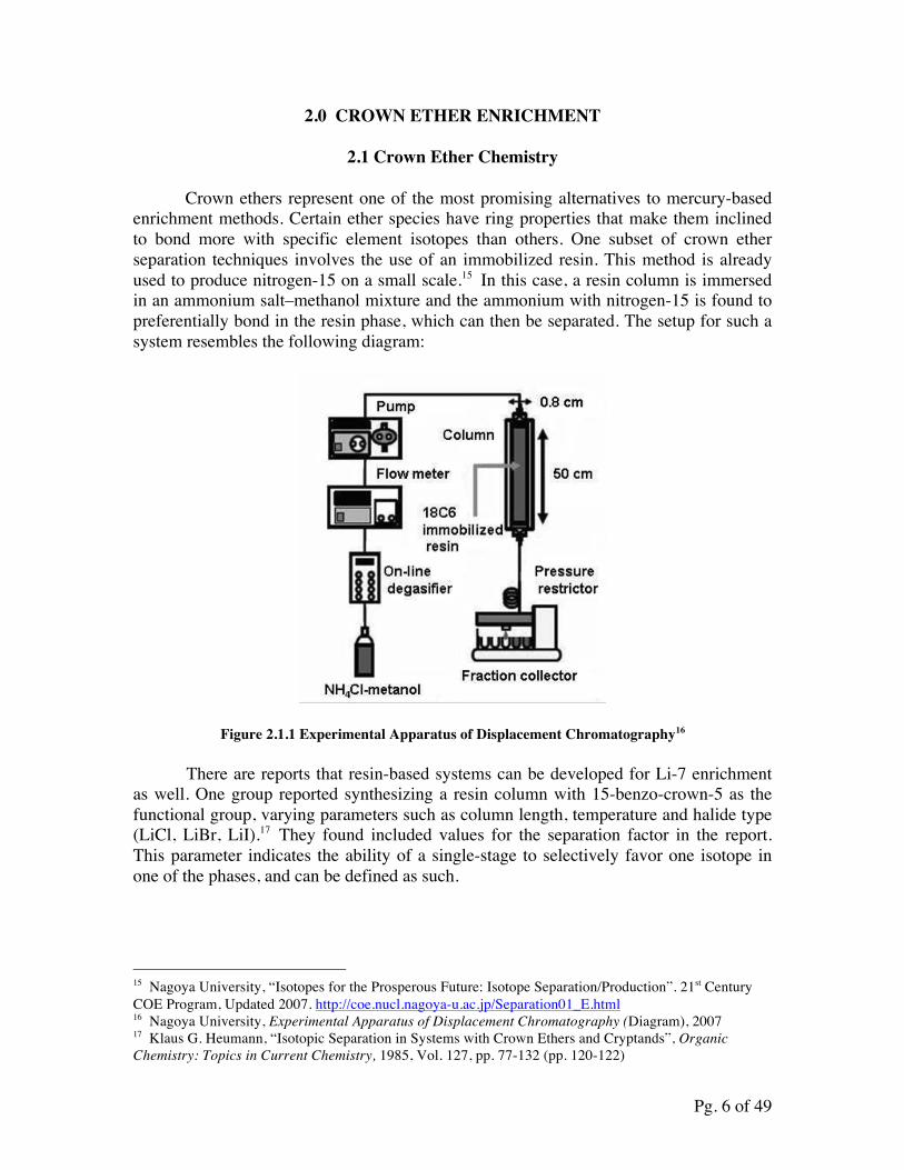
Equation 2.1.1
Separation factors as high as 1.047 were reported for systems on the low-end of the temperature spectrum (0 °C).18 This is comparable to separation figures reported for mercury processes, however, there are still some issues with relying on a resin-based process. For large-scale production, a column-based separation process will likely be ineffective at producing large quantities of product in a given unit of time with running costs expected to be high.
Fortunately, there is an alternate crown ether process to consider: liquid-liquid extraction. This is promising in that the solid phase can be avoided altogether and the process can be scaled-up. In this technique, a water-insoluble solvent containing the crown ethers is added to an aqueous mixture of lithium. After allowing a period of time for the crown ethers to distribute in the two solvent layers and form complexes, the Li-6 can be found preferentially in the solvent phase. Subsequent sections will discuss the types of materials being considered in this analysis, some potential drawbacks, and ultimately some conclusions on scaled-up processes.
2.2 Separation Method and Design
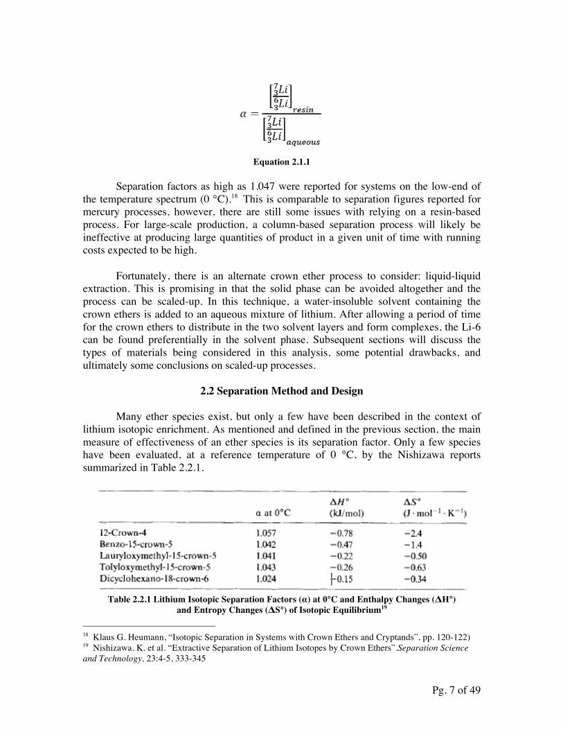
Many ether species exist, but only a few have been described in the context of lithium isotopic enrichment. As mentioned and defined in the previous section, the main measure of effectiveness of an ether species is its separation factor. Only a few species have been evaluated, at a reference temperature of 0 °C, by the Nishizawa reports summarized in Table 2.2.1.
Table 2.2.1 Lithium Isotopic Separation Factors (α) at 0°C and Enthalpy Changes (ΔH°)
and Entropy Changes (ΔS°) of Isotopic Equilibrium19
18 Klaus G. Heumann, “Isotopic Separation in Systems with Crown Ethers and Cryptands”, pp. 120-122) 19 Nishizawa, K. et al. “Extractive Separation of Lithium Isotopes by Crown Ethers”.Separation Science and Technology, 23:4-5, 333-345
Pg. 8 of 49
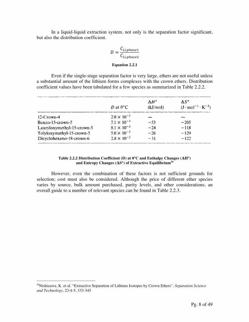
In a liquid-liquid extraction system, not only is the separation factor significant, but also the distribution coefficient.
! =!!",!!!"#!!!",!!!"#!
Equation 2.2.1
Even if the single-stage separation factor is very large, ethers are not useful unless a substantial amount of the lithium forms complexes with the crown ethers. Distribution coefficient values have been tabulated for a few species as summarized in Table 2.2.2.
Table 2.2.2 Distribution Coefficient (D) at 0°C and Enthalpy Changes (ΔH°)
and Entropy Changes (ΔS°) of Extractive Equilibrium20 However, even the combination of these factors is not sufficient grounds for selection; cost must also be considered. Although the price of different ether species varies by source, bulk amount purchased, purity levels, and other considerations, an overall guide to a number of relevant species can be found in Table 2.2.3.
20Nishizawa, K. et al. “Extractive Separation of Lithium Isotopes by Crown Ethers”. Separation Science and Technology, 23:4-5, 333-345
Pg. 9 of 49
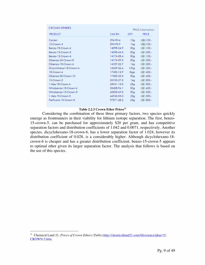
Table 2.2.3 Crown Ether Prices21
Considering the combination of these three primary factors, two species quickly emerge as frontrunners in their viability for lithium isotope separation. The first, benzo-15-crown-5, can be purchased for approximately $20 per gram, and has competitive separation factors and distribution coefficients of 1.042 and 0.0071, respectively. Another species, dicyclohexano-18-crown-6, has a lower separation factor of 1.024, however its distribution coefficient of 0.028, is a considerably higher. Although dicyclohexano-18-crown-6 is cheaper and has a greater distribution coefficient, benzo-15-crown-5 appears to optimal ether given its larger separation factor. The analysis that follows is based on the use of this species.
21 Chemical Land 21, Prices of Crown Ethers (Table),http://chemicalland21.com/lifescience/phar/15-CROWN-5.htm,
Pg. 10 of 49
3.0 Crown Ether Experiment
3.1 Overall Process
This section discusses the processes by which crown ethers can separate lithium isotopes and methods to measure the separation achieved, that can guide development of commercial-scale enrichment. A step-by-step plan for a process used in the lab to measure parameters related to the enrichment, and background information on materials and methods beyond those mentioned in section 2, is also provided.
3.1.1 Chemical Chemicals include the following but are not limited to: benzo-15-crown-5
(henceforth frequently referred to as 15-C-5), lithium chloride (LiCl), chloroform, dimethyl sulfoxide (DMSO), and distilled water. These are theoretical optimal choices, but other variants may also be tested. Reasons for the choices are justified below.
The choice of lithium salt is largely based on Gu’s report.22 After comparing cost, toxicity, and solubility in both the aqueous phase and the organic phase, LiCl is chosen for its better performance with chloroform as solvent. Typical researched lithium salts include LiCl, LiBr, LiI, LiSCN and CF3COOLi. Even though other chemicals like LiSCN and CF3COOLi have better separation factors, they are ruled out for either high toxicity or acidic conditions that are undesired because the stability of the crown ether is lower in an acidic environment. Lithium halides are generally cheaper, less toxic and have better distribution coefficients when combined with chloroform. Within halides, LiCl has the best solubility in chloroform and lowest cost. The separation factor of this system at 0oC is around 1.012; thus many more stages are needed though more research on salt selection could prove to be invaluable. Benzo-15-crown-5 (15-C-5) represents a compromise between distribution coefficients, separation factor and cost. For the time being crown ethers and cryptands are purchased on a small scale in gram quantities, resulting in high prices, and we expect the bulk price to drop significantly when purchasing in tons. However, relative price is still useful when comparing the cost of different choices. Many other crown ethers and cryptands may have higher separation factors, especially for cryptands which is comparable to traditional lithium amalgam. But their costs are so high that even with bulk pricing they could not be purchased on an industrial scale. The life expectation of crown ether species during industrial separation processes is yet unknown, but theoretically they are quite inert in non-acidic conditions and would not degrade quickly, typically 30~60 years.27 If later experiments show the life expectation of the crown ethers is shorter than stated above, then the cost of crown ether is a more important characteristic. Under that situation, cheaper crown ethers will be chosen at the expense of a lower separation factor. On the other hand, if the life expectation assumption is correct, then it can be considered as a capital investment. In this case, “better” ethers may be considered for replacement, i.e. benzo-15-crown-5. 22 Gu, Z, “Lithium Isotope Separation”, Progress in Chemistry, Vol.23, No. 9, Sep. 2011
Pg. 11 of 49
Benzo-15-crown-5 also has a decent distribution coefficient compared to other species: 0.0071 at room temperature. Its separation factor is relatively high, at 1.042.23 Pure crown ethers without derivatives are avoided due to possible miscibility with water,24 thus benzo-derivatives are used here.
After comparing several common candidates of organic solvent, chloroform appears to be the best option when considering equilibrium time and toxicity. Chloroform has a fast equilibrium time of five seconds, but its lower toxicity and history of industrial-scale usage makes it a good choice. In addition to that, similar to H2O↔H++OH-, chloroform is assumed to undergo CHCl3↔CHCl2
++Cl-, which is responsible for balancing charges when LiCl is absorbed into the organic phase. 24
Based on Nishizawa’s report, the presence of DMSO may improve the distribution coefficient by almost tenfold. Experimental research should be done to verify these claims as well as assess them for a variety of ether species. As it stands, the effects of DMSO have only been measured for a few ether species, and its interactions with 15-C-5 are poorly understood. Hu24 suggests that a solvent with greater polarity would increase the distribution coefficient, which may cause the DMSO effect, but this statement needs to be validated in future experiments.
3.1.2 Equipment
The distribution coefficient can be measured by flame photometry, using a flame photometer like the Microprocessor Flame Photometer 1381 from Environmental & Scientific Instruments Co. Exact instrumentation will largely depend on availability. Flame photometry is effective in measuring the concentrations of metals from groups 1 and 2 due to their low ionization energies. The distribution coefficient can be calculated by using the photometer to determine the lithium concentrations in each phase. This machine is most sensitive in certain concentration ranges, so dilutions may be necessary to place concentrations in the proper machine range.
The separation factor must be computed with more sensitive equipment, namely an inductively coupled plasma mass spectrometer (ICPMS). This device ionizes the particles it receives and separates them based on their mass-to-charge ratio.25,26 These devices are present in many modern labs, but most are not specifically designed to measure isotopic ratios. This ability can be granted by ICPMS machines equipped with a multi-collector (MC) system; however, such systems are considerably more difficult to come by. Most likely, this means that separation factors will be determined by a third-party lab, like Evans Analytical Group, as the instruments required are not readily available. 23Nishizawa, K. et al. “Extractive Separation of Lithium Isotopes by Crown Ethers”. Separation Science and Technology, 23:4-5, 333-345 24Hu, Jinbo, personal communication 25 University of Kentucky, “Flame Photometric Determination of Sodium”, Chemistry 126: Experiment 8. Jan. 2000. 26Kenichi Sakata et al., “Inductively Coupled Plasma Mass Spectrometer and Method”, U.S. patent 6265717 B1.
Pg. 12 of 49
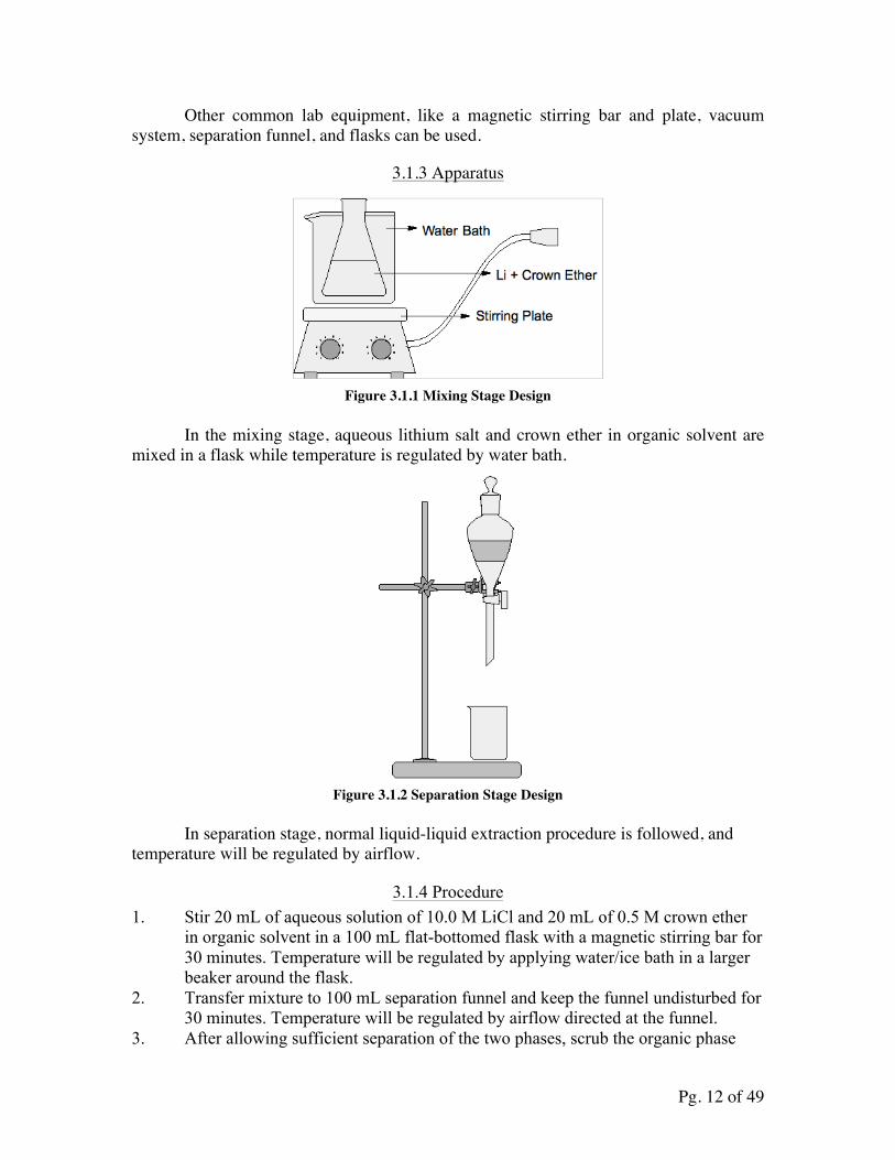
Other common lab equipment, like a magnetic stirring bar and plate, vacuum system, separation funnel, and flasks can be used.
3.1.3 Apparatus
Figure 3.1.1 Mixing Stage Design
In the mixing stage, aqueous lithium salt and crown ether in organic solvent are mixed in a flask while temperature is regulated by water bath.
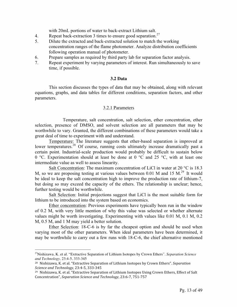
Figure 3.1.2 Separation Stage Design
In separation stage, normal liquid-liquid extraction procedure is followed, and temperature will be regulated by airflow.
3.1.4 Procedure 1. Stir 20 mL of aqueous solution of 10.0 M LiCl and 20 mL of 0.5 M crown ether
in organic solvent in a 100 mL flat-bottomed flask with a magnetic stirring bar for 30 minutes. Temperature will be regulated by applying water/ice bath in a larger beaker around the flask.
2. Transfer mixture to 100 mL separation funnel and keep the funnel undisturbed for 30 minutes. Temperature will be regulated by airflow directed at the funnel.
3. After allowing sufficient separation of the two phases, scrub the organic phase
Pg. 13 of 49
with 20mL portions of water to back-extract Lithium salt. 4. Repeat back-extraction 3 times to ensure good separation.27 5. Dilute the extracted and back-extracted solution to match the working
concentration ranges of the flame photometer. Analyze distribution coefficients following operation manual of photometer.
6. Prepare samples as required by third party lab for separation factor analysis. 7. Repeat experiment by varying parameters of interest. Run simultaneously to save
time, if possible.
3.2 Data
This section discusses the types of data that may be obtained, along with relevant equations, graphs, and data tables for different conditions, separation factors, and other parameters.
3.2.1 Parameters
Temperature, salt concentration, salt selection, ether concentration, ether selection, presence of DMSO, and solvent selection are all parameters that may be worthwhile to vary. Granted, the different combinations of these parameters would take a great deal of time to experiment with and understand. Temperature: The literature suggests that ether-based separation is improved at lower temperatures.28 Of course, running costs ultimately increase dramatically past a certain point. Industrial-scale production would probably be difficult to sustain below 0 °C. Experimentation should at least be done at 0 °C and 25 °C, with at least one intermediate value as well to assess linearity. Salt Concentration: The maximum concentration of LiCl in water at 20 °C is 18.3 M, so we are proposing testing at various values between 0.01 M and 15 M.29 It would be ideal to keep the salt concentration high to improve the production rate of lithium-7, but doing so may exceed the capacity of the ethers. The relationship is unclear; hence, further testing would be worthwhile. Salt Selection: Initial projections suggest that LiCl is the most suitable form for lithium to be introduced into the system based on economics. Ether concentration: Previous experiments have typically been run in the window of 0.2 M, with very little mention of why this value was selected or whether alternate values might be worth investigating. Experimenting with values like 0.01 M, 0.1 M, 0.2 M, 0.5 M, and 1 M may yield a better solution. Ether Selection: 18-C-6 is by far the cheapest option and should be used when varying most of the other parameters. When ideal parameters have been determined, it may be worthwhile to carry out a few runs with 18-C-6, the chief alternative mentioned
27Nishizawa, K. et al. “Extractive Separation of Lithium Isotopes by Crown Ethers”. Separation Science and Technology, 23:4-5, 333-345 28 Nishizawa, K. et al. “Extractive Separation of Lithium Isotopes by Crown Ethers”. Separation Science and Technology, 23:4-‐5, 333-‐345 29 Nishizawa, K. et al. “Extractive Separation of Lithium Isotopes Using Crown Ethers, Effect of Salt Concentration”, Separation Science and Technology, 23:6-‐7, 751-‐757
Pg. 14 of 49
in the literature. If this species performs comparatively to 15-C-5, it may be worthwhile to consider. Presence of DMSO: DMSO has been observed to improve the distribution coefficient of lithium by a factor of ten, bringing much more lithium into the organic phase. There are some concerns about its toxicity when used on a larger scale, but it should be reasonable to investigate on a small scale, and it is quite cheap.30 60 wt.% represents the upper concentration limit DMSO can consist of in an aqueous solution. 0, 20, 40 and 60 wt.% seem like reasonable values to check. Solvent Selection: Chloroform and nitrobenzene seem like the most worthwhile candidates; both should be tested.
3.2.2 Relevant Equations
D!"#$%&'/!"#$%#& =Li!"#$%&'Li!"#$%#&
Equation 3.2.1 Distribution coefficient
! =[!"− 6][!"− 7] !"#$%&'
/[!"− 6][!"− 7] !"#$%#&
Equation 3.2.2 Separation factor
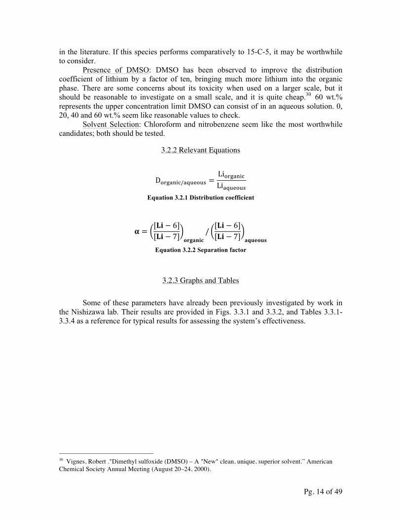
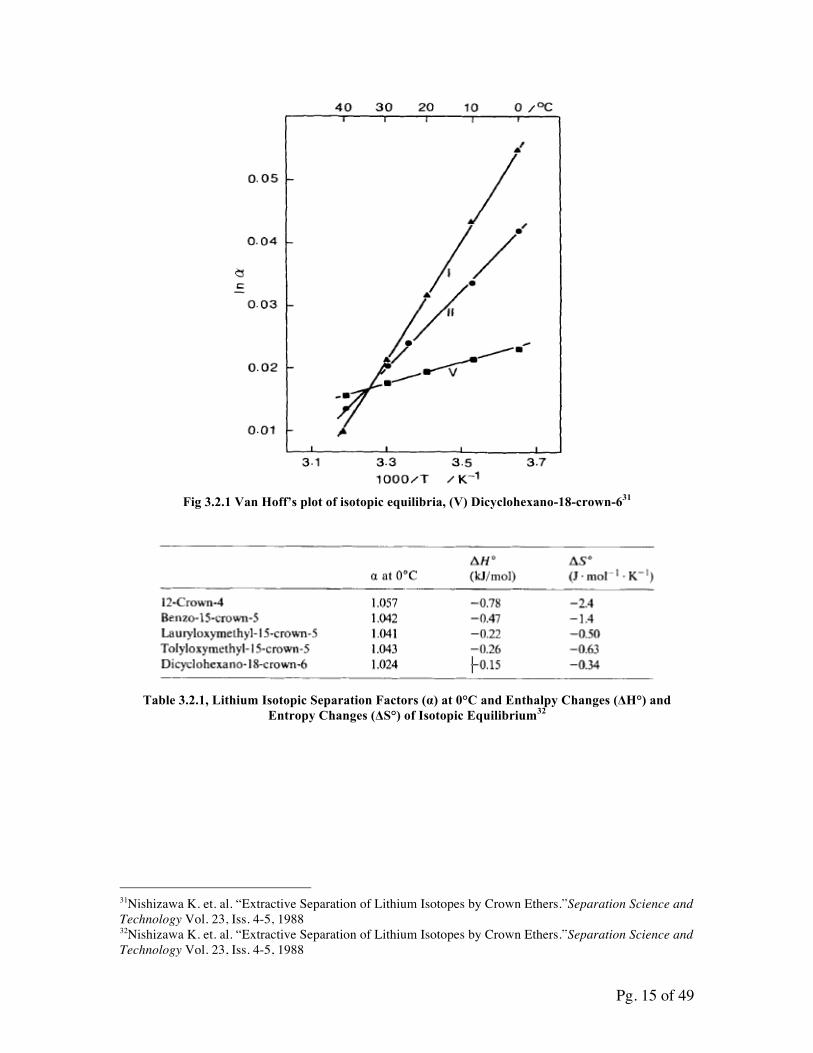
3.2.3 Graphs and Tables Some of these parameters have already been previously investigated by work in the Nishizawa lab. Their results are provided in Figs. 3.3.1 and 3.3.2, and Tables 3.3.1-3.3.4 as a reference for typical results for assessing the system’s effectiveness.
30 Vignes, Robert ."Dimethyl sulfoxide (DMSO) – A "New" clean, unique, superior solvent.” American Chemical Society Annual Meeting (August 20–24, 2000).
Pg. 15 of 49
Fig 3.2.1 Van Hoff’s plot of isotopic equilibria, (V) Dicyclohexano-18-crown-631
Table 3.2.1, Lithium Isotopic Separation Factors (α) at 0°C and Enthalpy Changes (ΔH°) and
Entropy Changes (ΔS°) of Isotopic Equilibrium32
31Nishizawa K. et. al. “Extractive Separation of Lithium Isotopes by Crown Ethers.”Separation Science and Technology Vol. 23, Iss. 4-5, 1988 32Nishizawa K. et. al. “Extractive Separation of Lithium Isotopes by Crown Ethers.”Separation Science and Technology Vol. 23, Iss. 4-5, 1988
Pg. 16 of 49
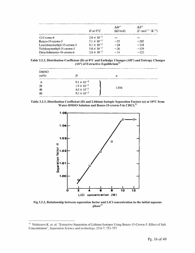
Table 3.2.2, Distribution Coefficient (D) at 0°C and Enthalpy Changes (ΔH°) and Entropy Changes
(ΔS°) of Extractive Equilibrium32
Table 3.2.3, Distribution Coefficient (D) and Lithium Isotopic Separation Factors (α) at 10°C from
Water-DMSO Solution and Benzo-15-crown-5 in CHCl332
Fig 3.2.2, Relationship between separation factor and LiCl concentration in the initial aqueous
phase33
33 Nishizawa K. et. al. “Extractive Separation of Lithium Isotopes Using Benzo-15-Crown-5. Effect of Salt Concentration”, Separation Science and technology, 23:6-7, 751-757
Pg. 17 of 49
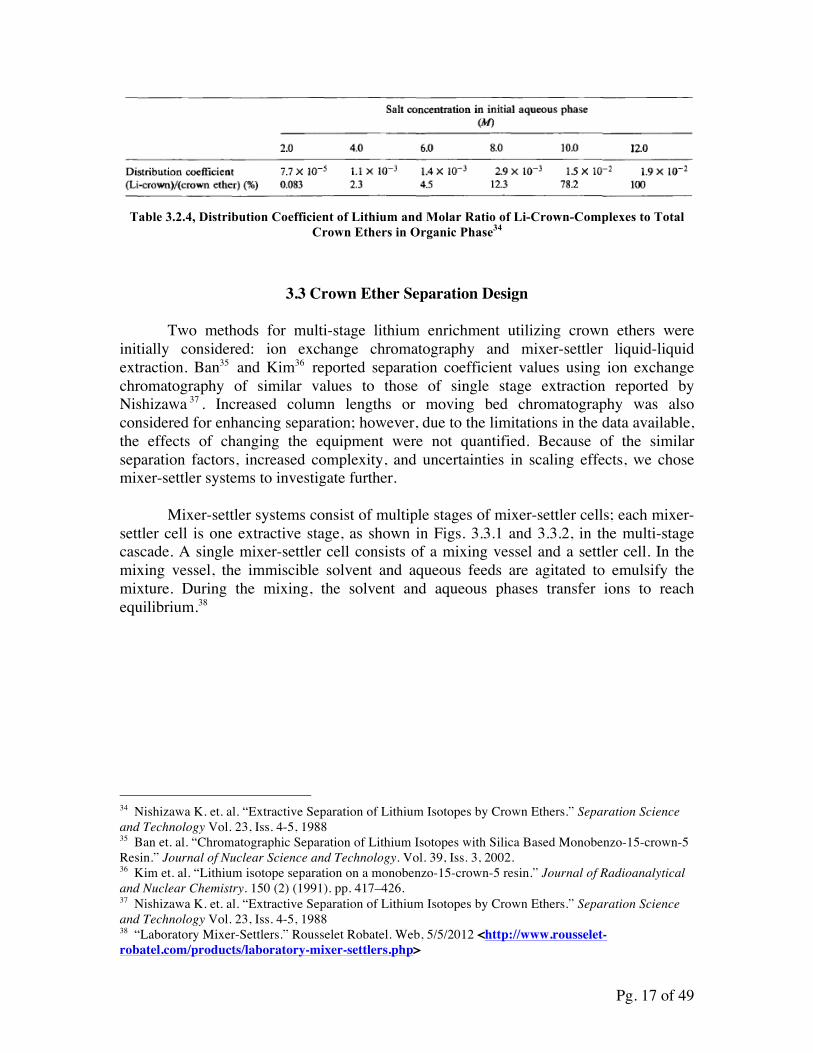
Table 3.2.4, Distribution Coefficient of Lithium and Molar Ratio of Li-Crown-Complexes to Total
Crown Ethers in Organic Phase34
3.3 Crown Ether Separation Design
Two methods for multi-stage lithium enrichment utilizing crown ethers were initially considered: ion exchange chromatography and mixer-settler liquid-liquid extraction. Ban35 and Kim36 reported separation coefficient values using ion exchange chromatography of similar values to those of single stage extraction reported by Nishizawa 37 . Increased column lengths or moving bed chromatography was also considered for enhancing separation; however, due to the limitations in the data available, the effects of changing the equipment were not quantified. Because of the similar separation factors, increased complexity, and uncertainties in scaling effects, we chose mixer-settler systems to investigate further.
Mixer-settler systems consist of multiple stages of mixer-settler cells; each mixer-settler cell is one extractive stage, as shown in Figs. 3.3.1 and 3.3.2, in the multi-stage cascade. A single mixer-settler cell consists of a mixing vessel and a settler cell. In the mixing vessel, the immiscible solvent and aqueous feeds are agitated to emulsify the mixture. During the mixing, the solvent and aqueous phases transfer ions to reach equilibrium.38
34 Nishizawa K. et. al. “Extractive Separation of Lithium Isotopes by Crown Ethers.” Separation Science and Technology Vol. 23, Iss. 4-5, 1988 35 Ban et. al. “Chromatographic Separation of Lithium Isotopes with Silica Based Monobenzo-15-crown-5 Resin.” Journal of Nuclear Science and Technology. Vol. 39, Iss. 3, 2002. 36 Kim et. al. “Lithium isotope separation on a monobenzo-15-crown-5 resin.” Journal of Radioanalytical and Nuclear Chemistry. 150 (2) (1991). pp. 417–426. 37 Nishizawa K. et. al. “Extractive Separation of Lithium Isotopes by Crown Ethers.” Separation Science and Technology Vol. 23, Iss. 4-5, 1988 38 “Laboratory Mixer-Settlers.” Rousselet Robatel. Web, 5/5/2012 <http://www.rousselet-robatel.com/products/laboratory-mixer-settlers.php>
Pg. 18 of 49
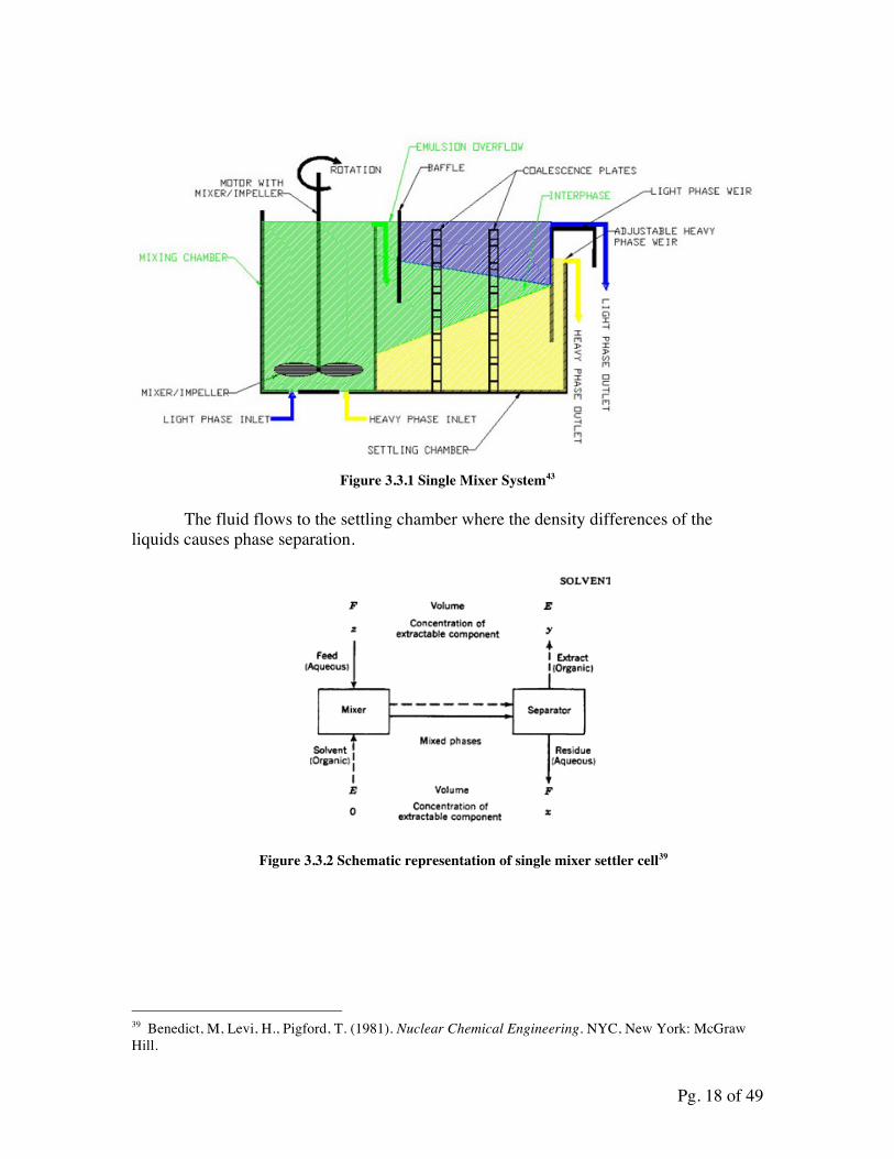
Figure 3.3.1 Single Mixer System43
The fluid flows to the settling chamber where the density differences of the liquids causes phase separation.
Figure 3.3.2 Schematic representation of single mixer settler cell39
39 Benedict, M, Levi, H., Pigford, T. (1981). Nuclear Chemical Engineering. NYC, New York: McGraw Hill.
Pg. 19 of 49
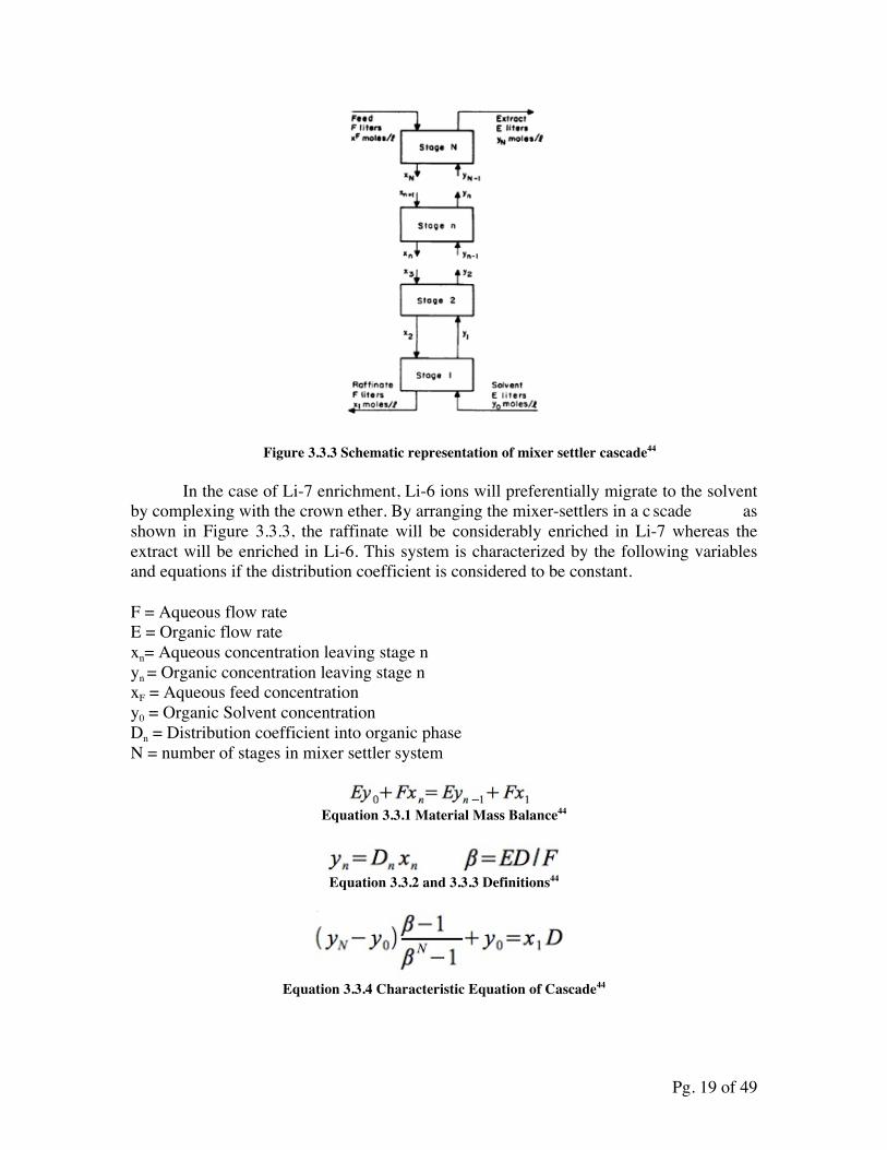
Figure 3.3.3 Schematic representation of mixer settler cascade44
In the case of Li-7 enrichment, Li-6 ions will preferentially migrate to the solvent by complexing with the crown ether. By arranging the mixer-settlers in a c scade as shown in Figure 3.3.3, the raffinate will be considerably enriched in Li-7 whereas the extract will be enriched in Li-6. This system is characterized by the following variables and equations if the distribution coefficient is considered to be constant.
F = Aqueous flow rate E = Organic flow rate xn= Aqueous concentration leaving stage n yn = Organic concentration leaving stage n xF = Aqueous feed concentration y0 = Organic Solvent concentration Dn = Distribution coefficient into organic phase N = number of stages in mixer settler system
Equation 3.3.1 Material Mass Balance44
Equation 3.3.2 and 3.3.3 Definitions44
Equation 3.3.4 Characteristic Equation of Cascade44
Pg. 20 of 49
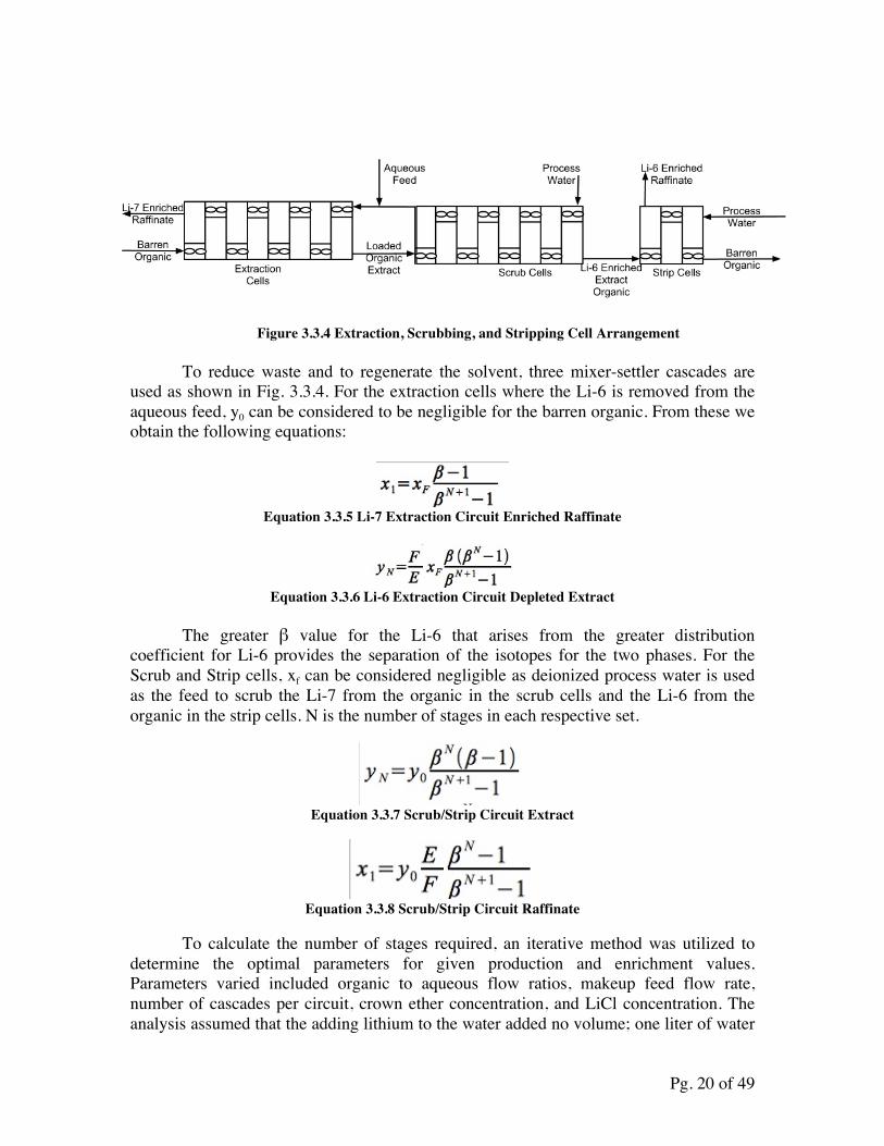
Figure 3.3.4 Extraction, Scrubbing, and Stripping Cell Arrangement
To reduce waste and to regenerate the solvent, three mixer-settler cascades are used as shown in Fig. 3.3.4. For the extraction cells where the Li-6 is removed from the aqueous feed, y0 can be considered to be negligible for the barren organic. From these we obtain the following equations:
Equation 3.3.5 Li-7 Extraction Circuit Enriched Raffinate
Equation 3.3.6 Li-6 Extraction Circuit Depleted Extract
The greater β value for the Li-6 that arises from the greater distribution coefficient for Li-6 provides the separation of the isotopes for the two phases. For the Scrub and Strip cells, xf can be considered negligible as deionized process water is used as the feed to scrub the Li-7 from the organic in the scrub cells and the Li-6 from the organic in the strip cells. N is the number of stages in each respective set.
Equation 3.3.7 Scrub/Strip Circuit Extract
Equation 3.3.8 Scrub/Strip Circuit Raffinate
To calculate the number of stages required, an iterative method was utilized to
determine the optimal parameters for given production and enrichment values. Parameters varied included organic to aqueous flow ratios, makeup feed flow rate, number of cascades per circuit, crown ether concentration, and LiCl concentration. The analysis assumed that the adding lithium to the water added no volume; one liter of water
Pg. 21 of 49
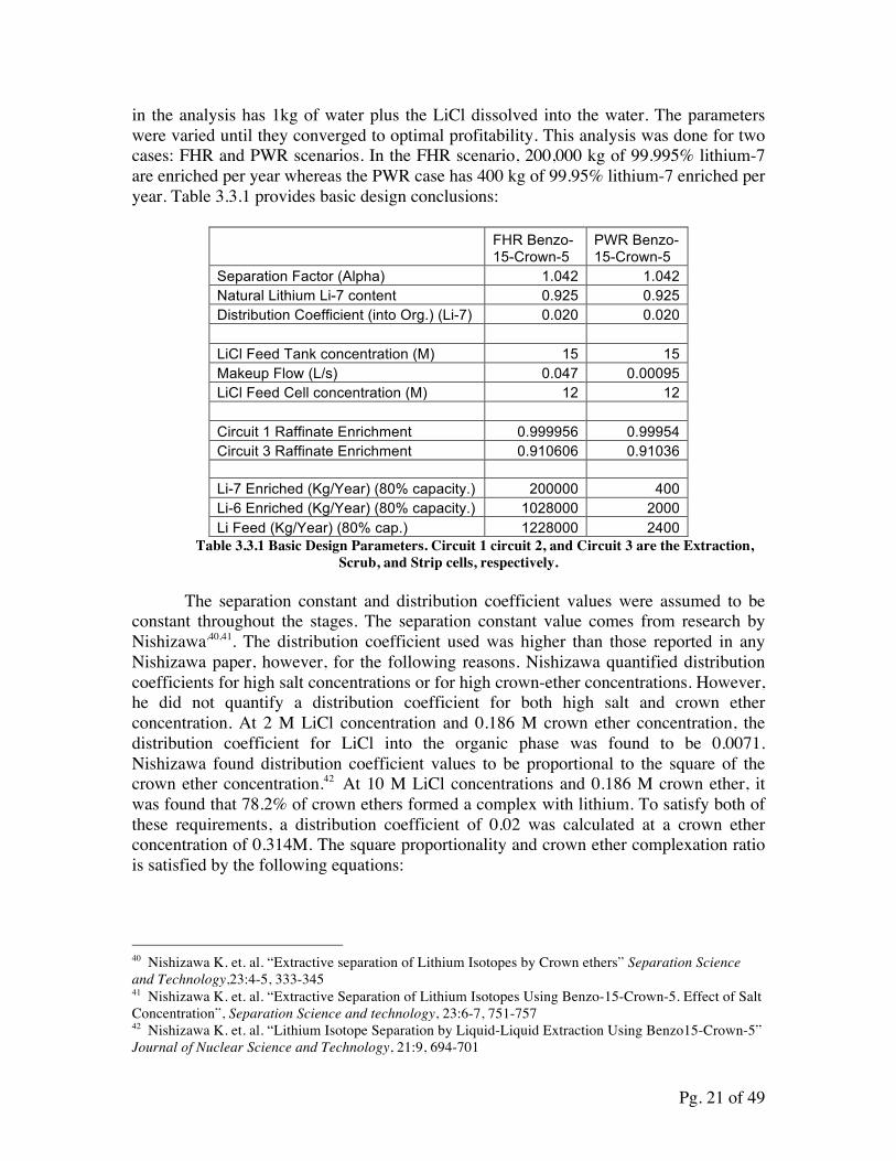
in the analysis has 1kg of water plus the LiCl dissolved into the water. The parameters were varied until they converged to optimal profitability. This analysis was done for two cases: FHR and PWR scenarios. In the FHR scenario, 200,000 kg of 99.995% lithium-7 are enriched per year whereas the PWR case has 400 kg of 99.95% lithium-7 enriched per year. Table 3.3.1 provides basic design conclusions:
FHR Benzo-15-Crown-5
PWR Benzo-15-Crown-5
Separation Factor (Alpha) 1.042 1.042 Natural Lithium Li-7 content 0.925 0.925 Distribution Coefficient (into Org.) (Li-7) 0.020 0.020 LiCl Feed Tank concentration (M) 15 15 Makeup Flow (L/s) 0.047 0.00095 LiCl Feed Cell concentration (M) 12 12 Circuit 1 Raffinate Enrichment 0.999956 0.99954 Circuit 3 Raffinate Enrichment 0.910606 0.91036 Li-7 Enriched (Kg/Year) (80% capacity.) 200000 400 Li-6 Enriched (Kg/Year) (80% capacity.) 1028000 2000 Li Feed (Kg/Year) (80% cap.) 1228000 2400
Table 3.3.1 Basic Design Parameters. Circuit 1 circuit 2, and Circuit 3 are the Extraction, Scrub, and Strip cells, respectively.
The separation constant and distribution coefficient values were assumed to be
constant throughout the stages. The separation constant value comes from research by Nishizawa,40,41. The distribution coefficient used was higher than those reported in any Nishizawa paper, however, for the following reasons. Nishizawa quantified distribution coefficients for high salt concentrations or for high crown-ether concentrations. However, he did not quantify a distribution coefficient for both high salt and crown ether concentration. At 2 M LiCl concentration and 0.186 M crown ether concentration, the distribution coefficient for LiCl into the organic phase was found to be 0.0071. Nishizawa found distribution coefficient values to be proportional to the square of the crown ether concentration.42 At 10 M LiCl concentrations and 0.186 M crown ether, it was found that 78.2% of crown ethers formed a complex with lithium. To satisfy both of these requirements, a distribution coefficient of 0.02 was calculated at a crown ether concentration of 0.314M. The square proportionality and crown ether complexation ratio is satisfied by the following equations:
40 Nishizawa K. et. al. “Extractive separation of Lithium Isotopes by Crown ethers” Separation Science and Technology,23:4-5, 333-345 41 Nishizawa K. et. al. “Extractive Separation of Lithium Isotopes Using Benzo-15-Crown-5. Effect of Salt Concentration”, Separation Science and technology, 23:6-7, 751-757 42 Nishizawa K. et. al. “Lithium Isotope Separation by Liquid-Liquid Extraction Using Benzo15-Crown-5” Journal of Nuclear Science and Technology, 21:9, 694-701
Pg. 22 of 49
C1=Nishizawa Crown Ether Concentration C2=Optimal Process Crown Ether Concentration D1=Nishizawa Distribution Coefficient D2=Optimal Distribution Coefficient
D2=D1(C22/C1
2) Equation 3.3.9
[LiCl]2*D2=.782*C2
Eq. 3.3.10
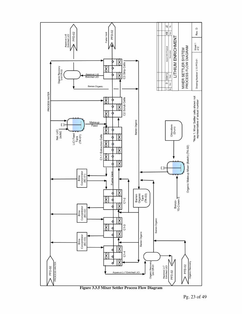
When evaluated, a higher distribution coefficient would be expected than .02, however a slightly lower distribution coefficient was selected to be conservative in the estimates, especially due to the ranges of LiCl concentrations that would be seen in the mixer settler cells. To maintain LiCl concentration in the range of 10M, brine concentrators were included to maintain the concentration between 12M and 8M. The following process flow diagrams illustrate the design that was utilized the optimal values.
Pg. 23 of 49
Figure 3.3.5 Mixer Settler Process Flow Diagram
Pg. 24 of 49
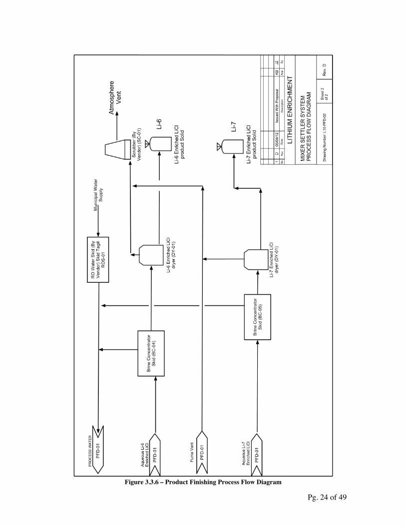
Figure 3.3.6 – Product Finishing Process Flow Diagram
Pg. 25 of 49
FHR Benzo-‐15-‐Crown-‐5
PWR Benzo-‐15-‐Crown-‐5
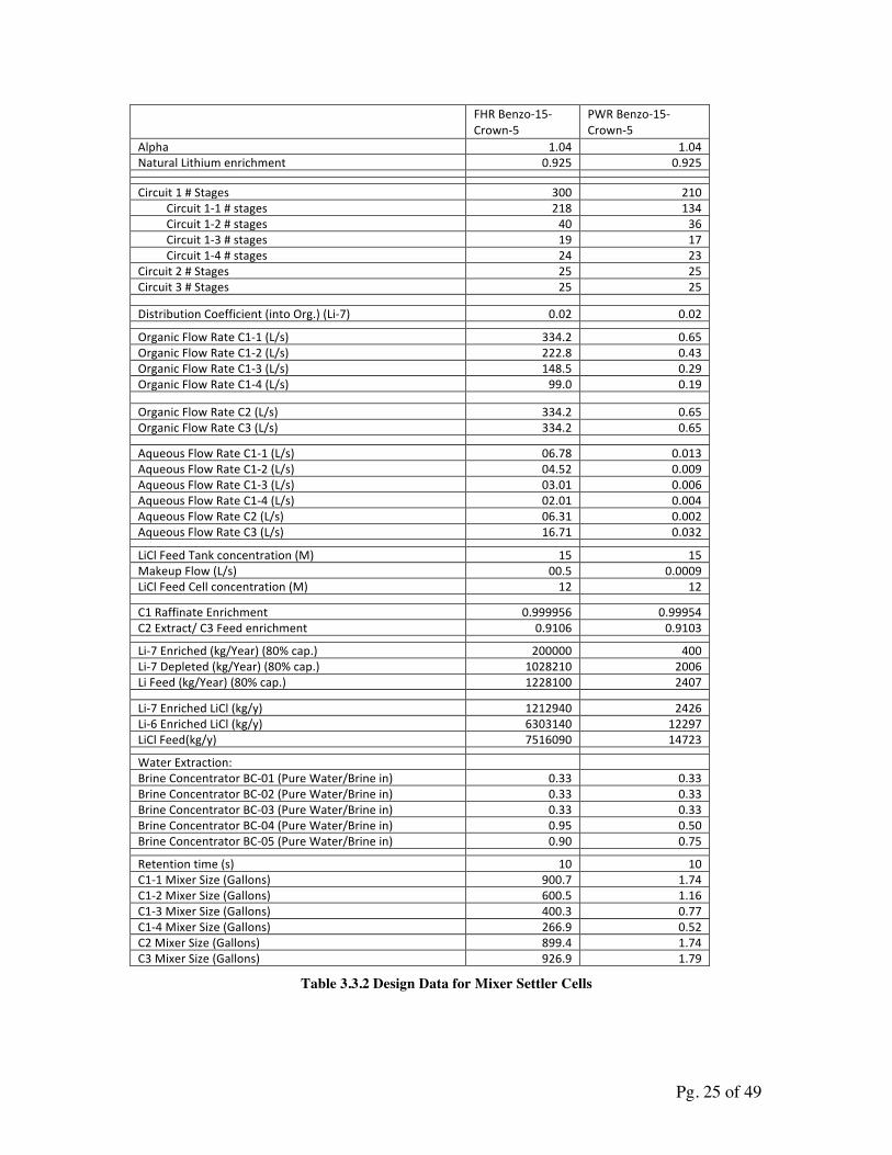
Alpha 1.04 1.04 Natural Lithium enrichment 0.925 0.925 Circuit 1 # Stages 300 210 Circuit 1-‐1 # stages 218 134 Circuit 1-‐2 # stages 40 36 Circuit 1-‐3 # stages 19 17 Circuit 1-‐4 # stages 24 23 Circuit 2 # Stages 25 25 Circuit 3 # Stages 25 25 Distribution Coefficient (into Org.) (Li-‐7) 0.02 0.02 Organic Flow Rate C1-‐1 (L/s) 334.2 0.65 Organic Flow Rate C1-‐2 (L/s) 222.8 0.43 Organic Flow Rate C1-‐3 (L/s) 148.5 0.29 Organic Flow Rate C1-‐4 (L/s) 99.0 0.19 Organic Flow Rate C2 (L/s) 334.2 0.65 Organic Flow Rate C3 (L/s) 334.2 0.65 Aqueous Flow Rate C1-‐1 (L/s) 06.78 0.013 Aqueous Flow Rate C1-‐2 (L/s) 04.52 0.009 Aqueous Flow Rate C1-‐3 (L/s) 03.01 0.006 Aqueous Flow Rate C1-‐4 (L/s) 02.01 0.004 Aqueous Flow Rate C2 (L/s) 06.31 0.002 Aqueous Flow Rate C3 (L/s) 16.71 0.032 LiCl Feed Tank concentration (M) 15 15 Makeup Flow (L/s) 00.5 0.0009 LiCl Feed Cell concentration (M) 12 12 C1 Raffinate Enrichment 0.999956 0.99954 C2 Extract/ C3 Feed enrichment 0.9106 0.9103 Li-‐7 Enriched (kg/Year) (80% cap.) 200000 400 Li-‐7 Depleted (kg/Year) (80% cap.) 1028210 2006 Li Feed (kg/Year) (80% cap.) 1228100 2407 Li-‐7 Enriched LiCl (kg/y) 1212940 2426 Li-‐6 Enriched LiCl (kg/y) 6303140 12297 LiCl Feed(kg/y) 7516090 14723 Water Extraction: Brine Concentrator BC-‐01 (Pure Water/Brine in) 0.33 0.33 Brine Concentrator BC-‐02 (Pure Water/Brine in) 0.33 0.33 Brine Concentrator BC-‐03 (Pure Water/Brine in) 0.33 0.33 Brine Concentrator BC-‐04 (Pure Water/Brine in) 0.95 0.50 Brine Concentrator BC-‐05 (Pure Water/Brine in) 0.90 0.75 Retention time (s) 10 10 C1-‐1 Mixer Size (Gallons) 900.7 1.74 C1-‐2 Mixer Size (Gallons) 600.5 1.16 C1-‐3 Mixer Size (Gallons) 400.3 0.77 C1-‐4 Mixer Size (Gallons) 266.9 0.52 C2 Mixer Size (Gallons) 899.4 1.74 C3 Mixer Size (Gallons) 926.9 1.79
Table 3.3.2 Design Data for Mixer Settler Cells
Pg. 26 of 49
Extraction LiCl Concentration
Stage # Enrichment No Concentrators
With Concentrators
1 0.999956 0.167 0.590 2 0.999955 0.331 1.171
23 0.999930 3.279 11.580 24 0.999928 3.398 12.000 25 0.999927 3.515 8.017 41 0.999896 5.170 11.792 42 0.999894 5.261 12.000 43 0.999891 5.351 8.037 44 0.999889 5.439 8.169 79 0.999752 7.836 11.769 82 0.999734 7.990 12.000 83 0.999728 8.040 8.040
100 0.999593 8.781 8.781 150 0.998609 10.144 10.144 200 0.995066 10.829 10.829 250 0.982260 11.283 11.283 300 0.937561 11.978 11.978
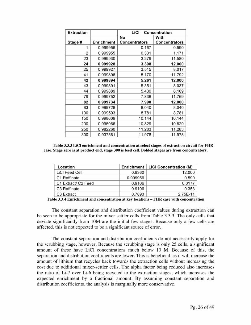
Table 3.3.3 LiCl enrichment and concentration at select stages of extraction circuit for FHR case. Stage zero is at product end, stage 300 is feed cell. Bolded stages are from concentrators.
Location Enrichment LiCl Concentration (M) LiCl Feed Cell 0.9360 12.000 C1 Raffinate 0.999956 0.590 C1 Extract/ C2 Feed 0.9106 0.0177 C3 Raffinate 0.9106 0.353 C3 Extract 0.7893 2.75E-11
Table 3.3.4 Enrichment and concentration at key locations – FHR case with concentration
The constant separation and distribution coefficient values during extraction can be seen to be appropriate for the mixer settler cells from Table 3.3.3. The only cells that deviate significantly from 10M are the initial few stages. Because only a few cells are affected, this is not expected to be a significant source of error.
The constant separation and distribution coefficients do not necessarily apply for the scrubbing stage, however. Because the scrubbing stage is only 25 cells, a significant amount of these have LiCl concentrations much below 10 M. Because of this, the separation and distribution coefficients are lower. This is beneficial, as it will increase the amount of lithium that recycles back towards the extraction cells without increasing the cost due to additional mixer-settler cells. The alpha factor being reduced also increases the ratio of Li-7 over Li-6 being recycled to the extraction stages, which increases the expected enrichment by a fractional amount. By assuming constant separation and distribution coefficients, the analysis is marginally more conservative.
Pg. 27 of 49
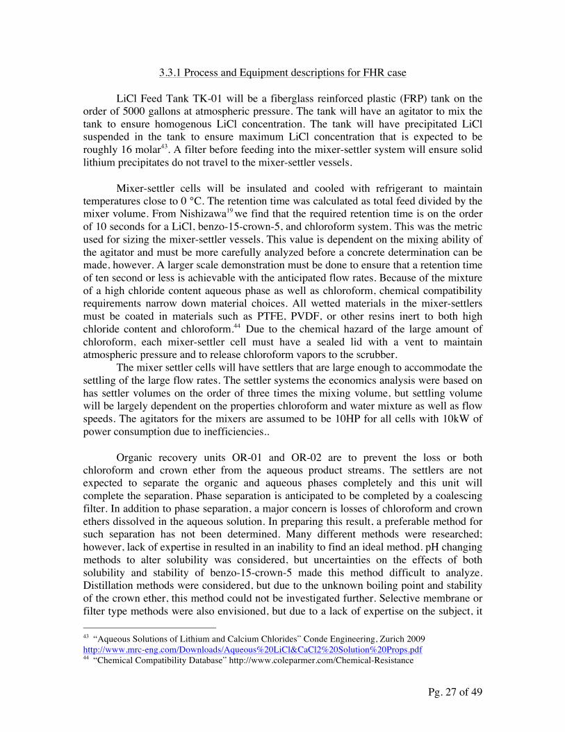
3.3.1 Process and Equipment descriptions for FHR case
LiCl Feed Tank TK-01 will be a fiberglass reinforced plastic (FRP) tank on the order of 5000 gallons at atmospheric pressure. The tank will have an agitator to mix the tank to ensure homogenous LiCl concentration. The tank will have precipitated LiCl suspended in the tank to ensure maximum LiCl concentration that is expected to be roughly 16 molar43. A filter before feeding into the mixer-settler system will ensure solid lithium precipitates do not travel to the mixer-settler vessels.
Mixer-settler cells will be insulated and cooled with refrigerant to maintain temperatures close to 0 °C. The retention time was calculated as total feed divided by the mixer volume. From Nishizawa19 we find that the required retention time is on the order of 10 seconds for a LiCl, benzo-15-crown-5, and chloroform system. This was the metric used for sizing the mixer-settler vessels. This value is dependent on the mixing ability of the agitator and must be more carefully analyzed before a concrete determination can be made, however. A larger scale demonstration must be done to ensure that a retention time of ten second or less is achievable with the anticipated flow rates. Because of the mixture of a high chloride content aqueous phase as well as chloroform, chemical compatibility requirements narrow down material choices. All wetted materials in the mixer-settlers must be coated in materials such as PTFE, PVDF, or other resins inert to both high chloride content and chloroform.44 Due to the chemical hazard of the large amount of chloroform, each mixer-settler cell must have a sealed lid with a vent to maintain atmospheric pressure and to release chloroform vapors to the scrubber.
The mixer settler cells will have settlers that are large enough to accommodate the settling of the large flow rates. The settler systems the economics analysis were based on has settler volumes on the order of three times the mixing volume, but settling volume will be largely dependent on the properties chloroform and water mixture as well as flow speeds. The agitators for the mixers are assumed to be 10HP for all cells with 10kW of power consumption due to inefficiencies..
Organic recovery units OR-01 and OR-02 are to prevent the loss or both chloroform and crown ether from the aqueous product streams. The settlers are not expected to separate the organic and aqueous phases completely and this unit will complete the separation. Phase separation is anticipated to be completed by a coalescing filter. In addition to phase separation, a major concern is losses of chloroform and crown ethers dissolved in the aqueous solution. In preparing this result, a preferable method for such separation has not been determined. Many different methods were researched; however, lack of expertise in resulted in an inability to find an ideal method. pH changing methods to alter solubility was considered, but uncertainties on the effects of both solubility and stability of benzo-15-crown-5 made this method difficult to analyze. Distillation methods were considered, but due to the unknown boiling point and stability of the crown ether, this method could not be investigated further. Selective membrane or filter type methods were also envisioned, but due to a lack of expertise on the subject, it 43 “Aqueous Solutions of Lithium and Calcium Chlorides” Conde Engineering, Zurich 2009 http://www.mrc-eng.com/Downloads/Aqueous%20LiCl&CaCl2%20Solution%20Props.pdf 44 “Chemical Compatibility Database” http://www.coleparmer.com/Chemical-Resistance
Pg. 28 of 49
was unknown if membranes could selectively remove chloroform and Benzo-15-Crown-5 this report assumes that one or more of these technologies can be implemented to efficiently recover chloroform and benzo-15-crown-5 from the aqueous stream to ppm or ppb levels.
Barren Organic Feed tank and Organic Makeup Mixer, TK-03 and TK-02, will only be in contact with chloroform and will be made of 304 Stainless or equivalent. The Barren Organic Feed Tank will be on the order of 10000 gallons to account for transients in mixer settler organic volumes. More detailed analysis may indicate that using multiple tanks is beneficial. The makeup mixer tank will be on the order of 500 gallons as organic losses are not expected to be substantial.
Brine concentrators BC-01, BC-02, BC-03, BC-04, and BC-05 will concentrate the LiCl aqueous streams to maintain the proper concentration. The design will be by vendors. Although the technology does not have to be of a specific type, RO (reverse osmosis) type desalination with concentrated brine stream is expected to be the ideal choice. Another choice would be falling film evaporators, but heating and re-cooling requirements may incur large energy costs. Deionizers that utilize ion-exchange resin beds will not be suitable as the purpose is to concentrate the brine rather than to remove the lithium and chlorine ions. BC-04 and BC-05 are used to reduce sizing and power requirements of dryers DY-01 and DY-02 by decreasing the liquid concentration of the brine. ROS-01 will be a high purity RO water filtration system to remove impurities from the municipal water supply. The brine concentrators may need to implement an organic recovery system as described for OR-01 and OR-02 if the membranes are not compatible with high chloroform concentrations, or, if using heated evaporators, if the crown ether is damaged by the heat. Although the chloroform and crown ethers can be left in the aqueous stream, if RO membranes are damaged by or do not filter chloroform, loss of solvent and/or poor membrane life will be expected. The Power requirements are approximated to be 2kW per GPM.
Dryers DY-01 and DY-02 are used to dry the aqueous Li-7 and Li-6 enriched product streams into solid LiCl to be sold. The dryers are tentatively planned to be spray dryers, but the design can be adjusted to incorporate other drying systems. The dryer will have to dehydrate the LiCl crystals to produce anhydrous LiCl. If the organic recovery systems create LiCl precipitates, the dryer will be a rotary kiln or other type of dryer to dehydrate the LiCl crystals.
Scrubber SC-01 is used to filter the chloroform vapors that are expected to evolve from the mixer-settler cells as well as the chloroform that will be liberated from the aqueous phase in the dryers. Due to the volume of the LiCl processed, the exhaust needs to be scrubbed. The scrubbing system will be designed by vendors. It is anticipated that the scrubber will consist of an activated carbon filter followed by an amine SCR (selective catalytic reactor) as is common for hydrocarbon scrubbing.
Pg. 29 of 49
The control system will utilize a PLC (programmable logic controller) system to automatically maintain steady state conditions for optimal lithium-7 production. VFDs (variable field drives) will control the agitators for the agitators are also the pumps pulling fluid from the adjacent cells. The control of the agitators will be the primary method of maintaining steady operation. In addition to this, control valves at key locations will be used. Level indicating transmitters shall be used in all mixer settlers to ensure proper separation of the organic and aqueous phases. Chemical analyzers will determine LiCl concentration at key areas such as the feed tank or before and after a brine concentrator unit. Vendor supplied systems will have their own control system. The initial setup will predominantly be done by adjusting the adjustable weir on the mixer-settler cells and hand operated valves between mixer-settlers. Isotopic analysis will be done by on-site mass spectroscopy. Flow rates of the mixer-settler system will be altered to ensure quality product at maximum production. If the separation is not great enough, flow rates can be lessened to increase retention time and hopefully increase isotopic separation. The refrigeration system is assumed to be a centrifugal chiller system that cools the mixer settler tanks through in-tank coolant coils. Heat exchangers will cool the process lines after brine concentrators BC-01, BC-02, and BC-03. Heat exchangers will chill fluids before and in feed tanks TK-01 and TK-03. It is assumed to have a coefficient of performance of 3. Cooling requirements are assumed to be equal to all energy that is being supplied to the mixer settler motors and brine concentrators. This is believed to be a reasonable estimate as the motors should be highly efficient and the heat transferred through the insulation should be small in comparison to the electric consumption.
3.3.2 Uncertainties and Unresolved Technical Problems
The largest uncertainties stem from a lack of knowledge about the expected behavior of the crown ethers. Because the distribution coefficient is inferred from previous experiments rather than directly measured, this value may be far from correct. The separation factor can also be expected to differ from small changes in the system. Ideally a mixer-settler type experiment can be performed to verify the performance of the ethers in more variable environments. A great concern that is currently not quantified is the lifetime of the crown ethers in the system. It is expected for the crown ethers to be useable for an extended period of time. A mechanism for crown ether loss is by escape through the product streams. As chloroform has a somewhat high solubility of 8 g/L57, it can be expected that the benzo-15-crown-5 will have some solubility in the aqueous phase. If the solubility in water is near the magnitude of chloroform, the organic recovery systems to remove the crown ether from the product streams so it can be recycled must be effective. Otherwise the cost of replacing the crown ethers will make the process prohibitively expensive.
The crown ethers are also expected to deteriorate from chemical processes. Although this is expected to be a slow process, this must be quantified and an appropriate method for replacing the ethers must be determined. Greater studies must be done on the
Pg. 30 of 49
stability of the benzo-15-crown-5 crown ether over a variety of conditions to ensure a long lifetime.
Another uncertainty is the use of RO membranes for concentrating of the brines. It is assumed that there are membranes available that will work with highly concentrated LiCl. If the concentration is too high for effective LiCl concentration through RO desalination, falling film evaporators or similar can be used.
3.4 Cost Estimate
Two separate cost estimates were carried out, one for a throughput of 400 kg/year enriched Li-7, enough to supply only the current U.S. PWRs, and the other for a throughput of 200 metric tons/year, for when there are 10 FHRs being built per year. Costs were calculated as total capital costs and total operating costs. The capital costs included initial procurement of chemicals, equipment costs, facility costs, construction, and installation costs for all the systems. The operating costs included chemicals for makeup, employee wages, and utilities to run the plant.
Capital costs, which would be incurred on a one-time basis are associated with setting up the separation plant itself. Most components and equipment costs are estimated to order of magnitude based on similar components found and their prices. Some of these prices are from confidential sources and thus details that can give identification have not been provided. Explanations for the cost estimates for the FHR case are as follows.
The mixer settler cells were based on the cost of FRP mixer settler cells with sealed lids, insulation, and agitator from 2011 from a confidential source. From this data, a fit in the form of a power equation was made. From this fit, the cost of the mixer settler cells was interpolated. The fit was determined to be 2723*V.531 where V is the mixer volume. To this cost, which did not include QAQC testing or Instrumentation, $10,000 was added to each cell. This resulted in a total cost estimate of 36 million dollars for the mixer settler cells.
The reverse osmosis (RO) systems were found priced as low as of $30,000-$80,000 each for flow rates in which we were interested, however, the 2011 price of a RO water system from the United States is much more expensive.45 From the same confidential source, the aggregate cost of 1020 GPM of RO water systems was roughly $5,000,000. For the mixer settler 200 tons per year production, assuming each step were single pass, approximately 380GPM of RO throughput is required. Assuming the price per GPM throughput would scales linearly down from 300GPM systems to the 50GPM range (the flow rate ranges of brine concentrators in design), it is assumed that it will cost about $5000 per GPM of single pass RO water for our system. Using a higher estimate of requiring 500GPM capacity, the cost estimate allocates $2.5 million dollars for RO Brine concentration/water recycling and municipal water treatment. The Chinese desalination skid was not utilized for pricing due to large uncertainties in the performance of the referenced unit. 45 “100m3/h RO brackish water desalination system.” Water Treatment..Alibaba.com. Web 5/4/2012 <http://www.alibaba.com/product-gs/263176797/100m3_h_RO_brackish_water_desalination.html>
Pg. 31 of 49
The cost of a brine evaporator system for comparison with RO membranes was analyzed from data from a four-effect falling film sodium chloride brine evaporator. The system analyzed was priced at $9 million for evaporating 350GPM of water. This price was significantly higher than the RO system estimates, even when excluding the additional price of a boiler system to supply steam to the evaporators, condensers, various tanks, and additional cooling requirements, however, the falling film evaporator can be used to
For a price reference, Chinese supplied spray dryers were found to be quoted at $10,000 to $500,000 for what appears to be 5 to 3000 kg/hr (.02 to 13 GPM) evaporative capacity.46 A used SPX flow technologies spray dryer was found to be $62,500 for .3GPM water evaporation ability.47 This suggests that the price differential for this system between Chinese and domestic suppliers is not as great as it was for RO water equipment. Chinese supplied equipment. Assuming that the brine concentrators can reduce the flow of the spray dryers to 20 GPM and 5 GPM or less for the Li-6 and Li-7 production stream, 3 $500,000 Chinese supplied spray evaporators can be utilized. Assuming that sourcing from the United States would be five times this price, $7.5 million to the dryers will be allocated to the dryers.
To produce an anhydrous product, rotary kiln dryers are proposed to be included with the dryer units if the spray dryers cannot sufficiently dry the product. For an American rotary kiln dryer capable of 26 tons per day of product (confidential source), it was seen that the 2011 price was $1.7 million dollars. Since the lithium enrichment plant is only expected to produce roughly 700 Kg/day of Li-7 and 3500 Kg/day of Li-6 enriched LiCl, allocating a million dollars to two rotary kiln dryers is expected to be appropriate.
Centrifugal chillers were found to cost $180000 to provide 2100kW of cooling to 4.5 °C (from confidential source). Assuming that cooling requirements are approximately equal to the electric consumption of the mixer settler cells and the brine concentrators, the heating requirements are estimated to be 3600kW. To satisfy the cooling requirements, the cost of two 2100kW chillers are allocated to chiller costs.
Motor control centers (MCC) with VFDs are approximated to cost 3.5 million dollars. This estimate comes from analyzing 2011 prices for MCCs housing a variety of buckets and inferring that the cost for a 10HP VFD bucket would be roughly $10,000 (confidential source). Due to the inability to convey this information in a censored form, it was excluded from appendix A as it would not have been helpful.
The electrical substation with transformers, switchgear, busducts, and other electrical equipment was found to be roughly $280,000 for 2500kVA (confidential
46 “LPG Series High Speed Centrifugal Atomizing Spray Dryer.” Drying Equipment. Alibaba.com. Web 5/4/2012 <http://www.alibaba.com/product-gs/350145704/LPG_Series_High_Speed_Centrifugal_Atomizing.html> 47 “ANHYDRO Spray Dryer, Cap. 427 lbs per/hr For Sale Used” Bid-On-Equipment.com. Web 6/10/2012 <http://www.bid-on-equipment.com/detail~id~114891.htm>
Pg. 32 of 49
source). The electrical power requirements for the plant are estimated to be 3500kW for the mixer settler agitators, 500kW for the brine concentrators, and 500kW for the other systems. Thus, 4500kW of power is needed and thus 5625kVA of apparent power.48 thus the cost is approximated as three of the 2500kVA systems to be roughly $775000.
Detailed cost estimating of tanks, pumps, instruments, and other smaller items were not performed for the uncertainties in other costs far outweigh the anticipated costs of these items. 3 million dollars is anticipated for tank, scrubber, pump, and auxiliary equipment costs. Instrumentation is factored into the price of the equipment for the skidded equipment. For the mixer settlers, 10000 dollars per cell was added for instrumentation and controls.
Facility costs were done based on an assumed $120 cost per sq. foot.49 Square footage was approximated as 120sqft per mixer settler cell plus 5000 sq ft for auxillary equipment. Dryers and substations are placed outside. This leads to an estimated cost of $5.7 million for the facility. This cost is extremely variable, especially if land prices are included. This estimate assumes that the land is already owned or freely provided by the government.
The installation cost was approximated to be 75% of the equipment costs.50 This assumption was to factor the costs of supports and anchoring, wiring, piping, and other details.
The starting material for the separation process, lithium chloride (LiCl), was found to be priced from $350-$400 per metric ton51. The chloroform that we need for the organic phase was found to cost $800-$850/ton.52 With shipping, both chloroform and lithium chloride was assumed to cost $1000 per metric ton and Chloroform to cost $2000 per metric ton. Assuming a 20 fold decrease in price due to industrial scale, the benzo-15-crown-5 ether costs $1000/kg. 53 This estimate is necessary for the crown ethers to be a viable option, but it is by far the largest uncertainty in the evaluation of the cost. As capital cost, it is estimated that the volume of chloroform in the mixer-settler cells is equal to 2.5 times the mixer settler volumes. This leads to approximately 700000 gallons of chloroform in the system, which correlates to $7.5 million in chloroform costs. With a molar concentration of .312, 222 metric tons of crown ether are needed. This results in a 48 “Power Calculator for Generators” www.dieselserviceandsuppli.com. Web 6/10/2012 <www.dieselserviceandsupply.com/Power_Calculator.aspx> 49 Selinger, B. “Facts & Figures: Building Costs” Illinois Department of commerce. www.commerce.state.il.us October 2011, Web 6/10/2012 <http://www.commerce.state.il.us/NR/rdonlyres/2E961958-4860-4526-806B-2705C5F42339/0/BuildingCosts.pdf> 50 Peters, M. S., Timmerhaus, K. D., West, R. E. (2003). Plant Design and Economics for Chemical Engineers. NYC, New York: McGraw-Hill. 51“Lithium Chloride, 7447-41-8.”Fine Chemical.Alibaba.com. Web. 4/12/2012 <http://srichem.en.alibaba.com/product/476535951-50416318/Lithium_Chloride_7447_41_8.html> 52“Chloroform.” Organic Intermediate.Alibaba.com. Web. 4/12/2012 <http://www.alibaba.com/product-gs/492259772/Chloroform.html> 53 Chemical Land 21, Prices of Crown Ethers (Table),http://chemicalland21.com/lifescience/phar/15-CROWN-5.htm,
Pg. 33 of 49
price of 222 million dollars. The ether and chloroform are reusable; however, due to finite solubility in the water, we have loss of some of each species. Thus there is a needed make-up of each chemical, so it is included in the operating costs. It is assumed that one fourth of these chemicals need to be replaced every year. Water is very cheap, priced at $1.5/1000 gallons.54 With the use of water recycling from the brine concentrators, little water is needed in the system. Electricity needed to run the plant is priced at roughly 10 cents/kW*hr.55 Replacement parts and consumables are estimated to be 5% of equipment cost per year. The last operating cost is employee salaries. We estimated a maximum of 20 employees after startup. Each employee would make about $80,000, thus a cost to the company of about $150,000 due to insurance, benefits, and other associated costs with employment.
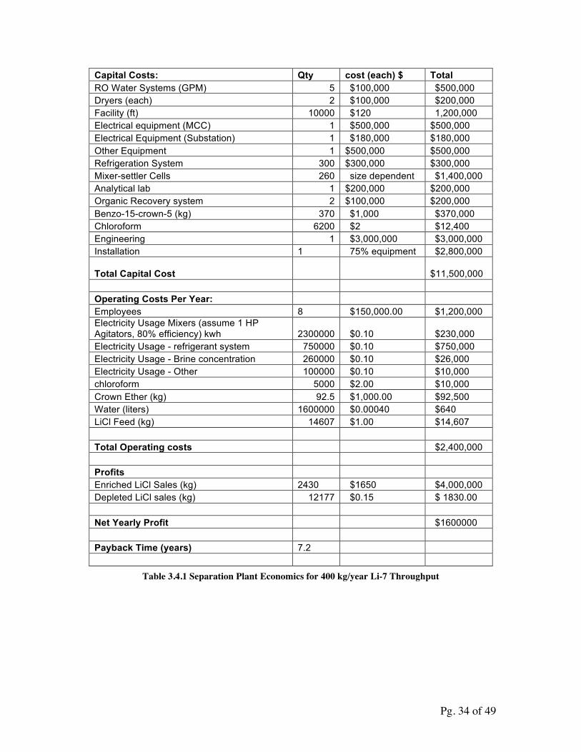
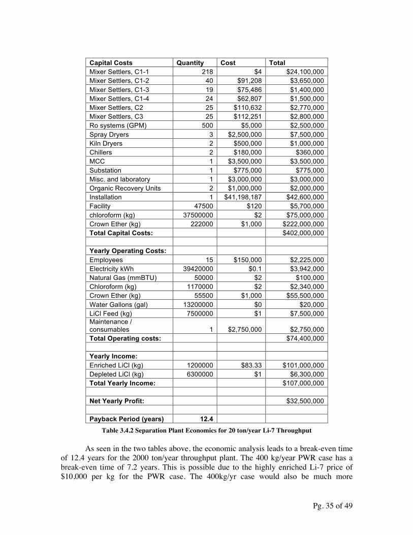
Table 3.5.1 shows a preliminary economic analysis with cost estimates and revenues for the 400 kg/yr enriched Li-7 throughput plant for PWR demand. Table 3.5.2 shows the economic analysis for 200 ton/yr enriched Li-7 throughput separation plant ran for FHR demands. The break-even point assumed that income would be adjusted with inflation, as well as a 0% rate of return, and 0% government interest loan.
54 “Is Water Free.” FCWA. Web. 5/5/2012 <http://www.fcwa.org/story_of_water/html/costs.htm> 55 “Electric Power Monthly.” EIA. Web, 5/5/2012 <http://www.eia.gov/electricity/monthly/epm_table_grapher.cfm?t=epmt_5_6_a>
Pg. 34 of 49
Capital Costs: Qty cost (each) $ Total RO Water Systems (GPM) 5 $100,000 $500,000 Dryers (each) 2 $100,000 $200,000 Facility (ft) 10000 $120 1,200,000 Electrical equipment (MCC) 1 $500,000 $500,000 Electrical Equipment (Substation) 1 $180,000 $180,000 Other Equipment 1 $500,000 $500,000 Refrigeration System 300 $300,000 $300,000 Mixer-settler Cells 260 size dependent $1,400,000 Analytical lab 1 $200,000 $200,000 Organic Recovery system 2 $100,000 $200,000 Benzo-15-crown-5 (kg) 370 $1,000 $370,000 Chloroform 6200 $2 $12,400 Engineering 1 $3,000,000 $3,000,000 Installation 1 75% equipment $2,800,000
Total Capital Cost $11,500,000
Operating Costs Per Year: Employees 8 $150,000.00 $1,200,000 Electricity Usage Mixers (assume 1 HP Agitators, 80% efficiency) kwh 2300000 $0.10 $230,000 Electricity Usage - refrigerant system 750000 $0.10 $750,000 Electricity Usage - Brine concentration 260000 $0.10 $26,000 Electricity Usage - Other 100000 $0.10 $10,000 chloroform 5000 $2.00 $10,000 Crown Ether (kg) 92.5 $1,000.00 $92,500 Water (liters) 1600000 $0.00040 $640 LiCl Feed (kg) 14607 $1.00 $14,607 Total Operating costs $2,400,000 Profits Enriched LiCl Sales (kg) 2430 $1650 $4,000,000 Depleted LiCl sales (kg) 12177 $0.15 $ 1830.00 Net Yearly Profit $1600000 Payback Time (years) 7.2
Table 3.4.1 Separation Plant Economics for 400 kg/year Li-7 Throughput
Pg. 35 of 49
Capital Costs Quantity Cost Total Mixer Settlers, C1-1 218 $4 $24,100,000 Mixer Settlers, C1-2 40 $91,208 $3,650,000 Mixer Settlers, C1-3 19 $75,486 $1,400,000 Mixer Settlers, C1-4 24 $62,807 $1,500,000 Mixer Settlers, C2 25 $110,632 $2,770,000 Mixer Settlers, C3 25 $112,251 $2,800,000 Ro systems (GPM) 500 $5,000 $2,500,000 Spray Dryers 3 $2,500,000 $7,500,000 Kiln Dryers 2 $500,000 $1,000,000 Chillers 2 $180,000 $360,000 MCC 1 $3,500,000 $3,500,000 Substation 1 $775,000 $775,000 Misc. and laboratory 1 $3,000,000 $3,000,000 Organic Recovery Units 2 $1,000,000 $2,000,000 Installation 1 $41,198,187 $42,600,000 Facility 47500 $120 $5,700,000 chloroform (kg) 37500000 $2 $75,000,000 Crown Ether (kg) 222000 $1,000 $222,000,000 Total Capital Costs: $402,000,000 Yearly Operating Costs: Employees 15 $150,000 $2,225,000 Electricity kWh 39420000 $0.1 $3,942,000 Natural Gas (mmBTU) 50000 $2 $100,000 Chloroform (kg) 1170000 $2 $2,340,000 Crown Ether (kg) 55500 $1,000 $55,500,000 Water Gallons (gal) 13200000 $0 $20,000 LiCl Feed (kg) 7500000 $1 $7,500,000 Maintenance / consumables 1 $2,750,000 $2,750,000 Total Operating costs: $74,400,000 Yearly Income: Enriched LiCl (kg) 1200000 $83.33 $101,000,000 Depleted LiCl (kg) 6300000 $1 $6,300,000 Total Yearly Income: $107,000,000 Net Yearly Profit: $32,500,000 Payback Period (years) 12.4
Table 3.4.2 Separation Plant Economics for 20 ton/year Li-7 Throughput
As seen in the two tables above, the economic analysis leads to a break-even time of 12.4 years for the 2000 ton/year throughput plant. The 400 kg/year PWR case has a break-even time of 7.2 years. This is possible due to the highly enriched Li-7 price of $10,000 per kg for the PWR case. The 400kg/yr case would also be much more
Pg. 36 of 49
economical if it were built at an existing facility where employees already work 24/7. It is anticipated that the system cannot be ran and stopped frequently with ease, thus the system requires people to be available 24/7, however, the system really only requires people to be on site on nightshift to oversee the equipment in case of unexpected troubles. At an existing facility, only a few dedicated employees would be necessary for the operation of the 400kg/yr case due to the small size of the equipment involved.
The economics of the FHR case is highly dependent on the cost of the crown ethers and the rate of loss from the system. Over 50% of the capital expenses and over 75% of operating expenses are currently attributed to the crown ether. The 20-factor decrease in price was estimate made without much analysis to determine an upper bound on the price of benzo-15-crown-5. A study on the production of benzo-15-crown-5 and detailed analysis as to the economics of large-scale benzo-15-crown-5 must be done before better economic estimates can be made. SWU calculations were not carried out for mixer-settler systems because the mixer-settler cells are not reconfigurable, and thus the costs do not scale with SWUs, unlike in the centrifuge systems.
3.5 Feasibility of Model
From the economic analysis, the crown ether method seems to be feasible for large-scale production on the FHR level, a throughput of 200 tons/year. The production for PWR grade LiCl also appears to be cost effective due to the high price utilities are willing to pay for the enriched lithium. However, the 20 fold price decrease in the 400KG/year production case may be too optimistic. If this price decrease cannot be achieved, the cost of the plant would be much higher. Difficulties with the crown ether method would be the lack of experimental data for how each of the chemicals behave, as well as characteristic data for the variability of the separation factor and distribution coefficient over concentration ranges, and the amount of recycling of chemicals possible in this system.
Pg. 37 of 49
4.0 AVLIS
4.1 Overview
Atomic vapor laser isotope separation (AVLIS) is a very promising separation technique originally developed to enrich uranium for weapons purposes.56 The method uses hyperfine structure differences between isotopes to selectively ionize one of them. When passed through an electromagnetic field, the ionized particles will drift while the neutral isotopes do not, making the former available for collection. Not much research has been conducted using AVLIS for Lithium separation; however, it is becoming increasingly important because of its high-energy efficiency, high separation factor, low waste, and low signature, making it an attractive option for commercial enriched Lithium production.
AVLIS was originally developed as an alternative to calutron enrichment of uranium for atomic weapons. Only more recently has it been considered for Lithium enrichment; the components of AVLIS, such as a vacuum, a dye-laser, and collector plates are older technology used in numerous unrelated applications. Therefore, designing an industrial process using AVLIS to enrich Lithium should be relatively simple. However issues in the realistic enrichment capability and scaling must first be resolved. While perfect selectivity is possible in principle, it remains to be seen whether the throughput and non-selective pickup can be optimized to allow for industrial scale production of enriched Li-7 for use in PWRs and FHRs.
Very little work has been done directly on the separation of Lithium using AVLIS, especially for the purpose of large-scale enriched Lithium production. In 1999 Henrick Strydom published his PhD dissertation on mass spectrometry of laser-produced products, which incidentally included enriched Lithium produced with AVLIS.57 His experiment included an in-situ time-of-flight (TOF) mass spectrometer to measure Lithium isotopic separation, showing perfect selective photo-ionization of Li-7. In 2004, Karl Scheibner published work on using AVLIS for general isotopic separation, focusing a variety of elements.58 While Lithium was not among them, he uncovered a lot of detail on potential throughput and non-selective pickup values. Due to its lower mass and similar chemical properties to Pb and Os, which he found to have high relative throughput with AVLIS, enriched Lithium is a prime candidate for industrial scale production. However it must be shown that this process is scalable and economically feasible before it can be considered for commercial application.
56 “Laser Isotope Separation Uranium Enrichment”. Globalsecurity.org. <http://www.globalsecurity.org/wmd/intro/u-laser.htm>. 5/5/2012. 57 Strydom, H. J. “Mass Spectrometry Characterization of Laser Produced Products”. Physics Theses. University of Natal. Durban, South Africa. December, 1999. 58 Scheibner, K. “Cost Estimate for Laser Isotope Separation for RIA”. LLNL Report.5 November 2004. Web. 2/27/2012 <https://e-reports-ext.llnl.gov/pdf/313426.pdf>
Pg. 38 of 49
4.2 AVLIS Concepts and Components
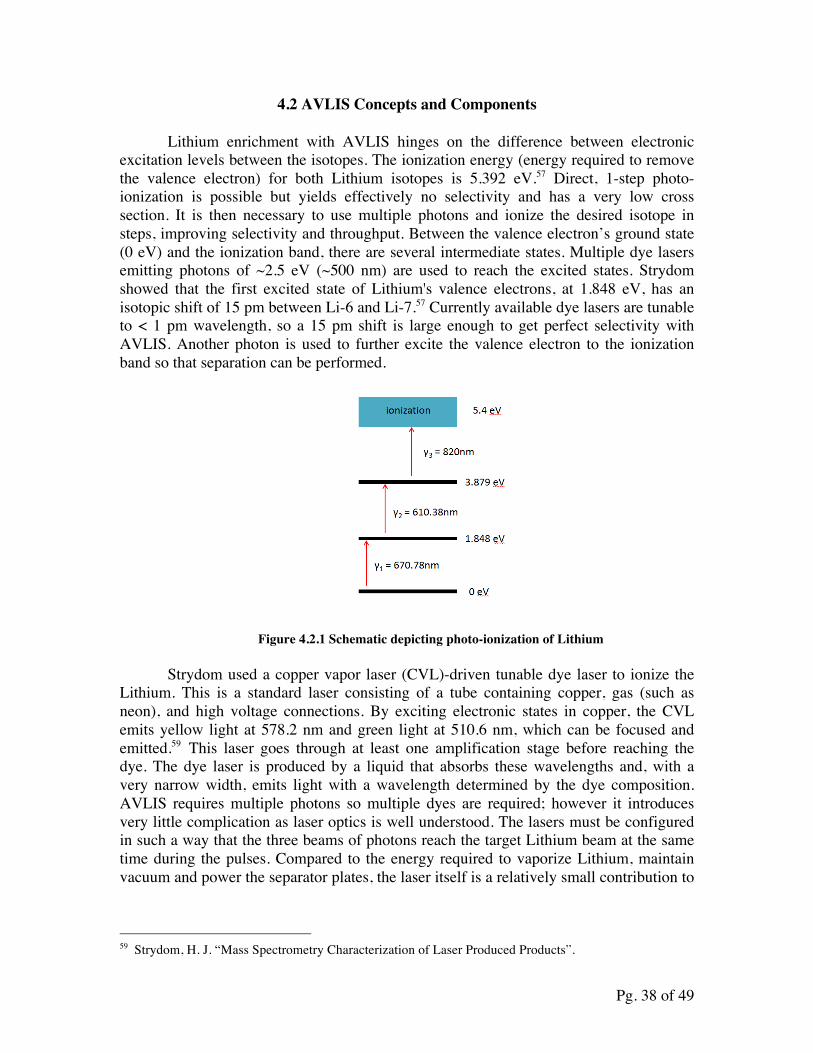
Lithium enrichment with AVLIS hinges on the difference between electronic excitation levels between the isotopes. The ionization energy (energy required to remove the valence electron) for both Lithium isotopes is 5.392 eV.57 Direct, 1-step photo-ionization is possible but yields effectively no selectivity and has a very low cross section. It is then necessary to use multiple photons and ionize the desired isotope in steps, improving selectivity and throughput. Between the valence electron’s ground state (0 eV) and the ionization band, there are several intermediate states. Multiple dye lasers emitting photons of ~2.5 eV (~500 nm) are used to reach the excited states. Strydom showed that the first excited state of Lithium's valence electrons, at 1.848 eV, has an isotopic shift of 15 pm between Li-6 and Li-7.57 Currently available dye lasers are tunable to < 1 pm wavelength, so a 15 pm shift is large enough to get perfect selectivity with AVLIS. Another photon is used to further excite the valence electron to the ionization band so that separation can be performed.
Figure 4.2.1 Schematic depicting photo-ionization of Lithium
Strydom used a copper vapor laser (CVL)-driven tunable dye laser to ionize the Lithium. This is a standard laser consisting of a tube containing copper, gas (such as neon), and high voltage connections. By exciting electronic states in copper, the CVL emits yellow light at 578.2 nm and green light at 510.6 nm, which can be focused and emitted.59 This laser goes through at least one amplification stage before reaching the dye. The dye laser is produced by a liquid that absorbs these wavelengths and, with a very narrow width, emits light with a wavelength determined by the dye composition. AVLIS requires multiple photons so multiple dyes are required; however it introduces very little complication as laser optics is well understood. The lasers must be configured in such a way that the three beams of photons reach the target Lithium beam at the same time during the pulses. Compared to the energy required to vaporize Lithium, maintain vacuum and power the separator plates, the laser itself is a relatively small contribution to
59 Strydom, H. J. “Mass Spectrometry Characterization of Laser Produced Products”.
Pg. 39 of 49
the overall energy requirements for separation. In addition, this particular laser technology is decades old and proven to be scalable, making it ideal for this application.60
The separators simply consist of conducting plates separated by a small distance. A high voltage bias is applied, creating an electric field between the plates. The electric field pushes the ionized Lithium toward a collector plate while neutral atoms continue in a straight line. Strydom initially experienced issues with non-selective pickup, that is, Lithium from the beam getting on the collection plates. Sheibner, however, showed that this can be reduced to less than 1% contamination.61 The RIA experiment used a slightly different technique to produce and collimate a vapor beam, though it is unclear if this will work with Lithium. Removal of the enriched Lithium product and depleted tails from the plates is simple and does not require much labor or time. Separation of Lithium from the collector plates can be done by simply heating them up as Lithium has a low melting temperature of 180° C, compared to copper (a potential plate material), which melts at ~1080° C.62 Since this process involves little time and labor, the differential operating costs for AVLIS are low.
To minimize contamination on the collector plates and to ensure a straight, well-collimated beam, exposure to laser photons is done in a vacuum. A standard vacuum is used with P ~ 10-6torr, which can be accomplished utilizing a typical oil diffusion pump, contributing to the simplicity and scalability of the process. The enclosure must be large enough to allow enough time for the beam to be exposed. Depending on the method used to vaporize the Lithium, the Lithium atoms travel at ~2000 m/s. The laser is pulsed and lasts a finite amount of time, so the geometry must allow for the light to hit the Lithium atoms. More generally, Lithium vapor enters one end of the chamber and is collimated by several slits or holes. Afterwards it passes by a window in the vacuum chamber, at which point photons excite and ionize valence electrons in the Li-7 atoms. The beam then passes between biased plates where an electromagnetic field deflects the ionized Li-7 onto a collector plate while the tails are collected on a second plate. Once the vapor source is depleted, the product can be separated from the plates.
4.3 Strydom’s Experimental Setup
AVLIS (Fig. 4.2.1) involves vaporizing Lithium, collimating the vapor into a beam, shining it with a very finely tuned dye-laser, and separating the selectively ionized atoms with an electromagnetic field.63 A diagram of the process is pictured below:
60 Barnes, Clive. “Copper at the Cutting Edge: The Copper Vapor Laser”. Copper Development Association Inc. www.copper.org. June 2001. < http://www.copper.org/publications/newsletters/innovations/2001/06/cutting_edge.html> . 5/5/2012. 61Scheibner, K. “Cost Estimate for Laser Isotope Separation for RIA”. 62 “Copper vs. Lithium”. Find the Data: Side-by-Side. Findthedata.org. <http://chemical-elements.findthedata.org/compare/24-51/Copper-vs-Lithium> 5/5/2012. 63 Strydom, H. J. “Mass Spectrometry Characterization of Laser Produced Products”.
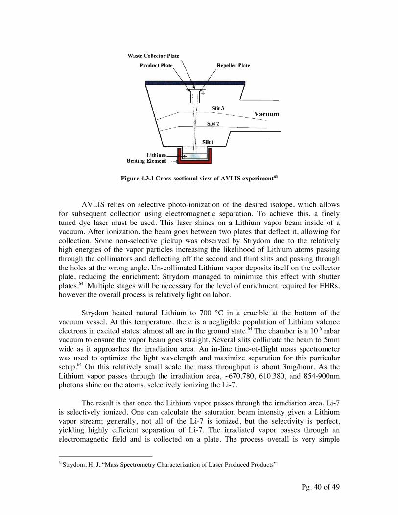
Pg. 40 of 49
Figure 4.3.1 Cross-sectional view of AVLIS experiment63
AVLIS relies on selective photo-ionization of the desired isotope, which allows for subsequent collection using electromagnetic separation. To achieve this, a finely tuned dye laser must be used. This laser shines on a Lithium vapor beam inside of a vacuum. After ionization, the beam goes between two plates that deflect it, allowing for collection. Some non-selective pickup was observed by Strydom due to the relatively high energies of the vapor particles increasing the likelihood of Lithium atoms passing through the collimators and deflecting off the second and third slits and passing through the holes at the wrong angle. Un-collimated Lithium vapor deposits itself on the collector plate, reducing the enrichment; Strydom managed to minimize this effect with shutter plates.64 Multiple stages will be necessary for the level of enrichment required for FHRs, however the overall process is relatively light on labor.
Strydom heated natural Lithium to 700 °C in a crucible at the bottom of the vacuum vessel. At this temperature, there is a negligible population of Lithium valence electrons in excited states; almost all are in the ground state.64 The chamber is a 10-6 mbar vacuum to ensure the vapor beam goes straight. Several slits collimate the beam to 5mm wide as it approaches the irradiation area. An in-line time-of-flight mass spectrometer was used to optimize the light wavelength and maximize separation for this particular setup.64 On this relatively small scale the mass throughput is about 3mg/hour. As the Lithium vapor passes through the irradiation area, ~670.780, 610.380, and 854-900nm photons shine on the atoms, selectively ionizing the Li-7.
The result is that once the Lithium vapor passes through the irradiation area, Li-7 is selectively ionized. One can calculate the saturation beam intensity given a Lithium vapor stream; generally, not all of the Li-7 is ionized, but the selectivity is perfect, yielding highly efficient separation of Li-7. The irradiated vapor passes through an electromagnetic field and is collected on a plate. The process overall is very simple
64Strydom, H. J. “Mass Spectrometry Characterization of Laser Produced Products”
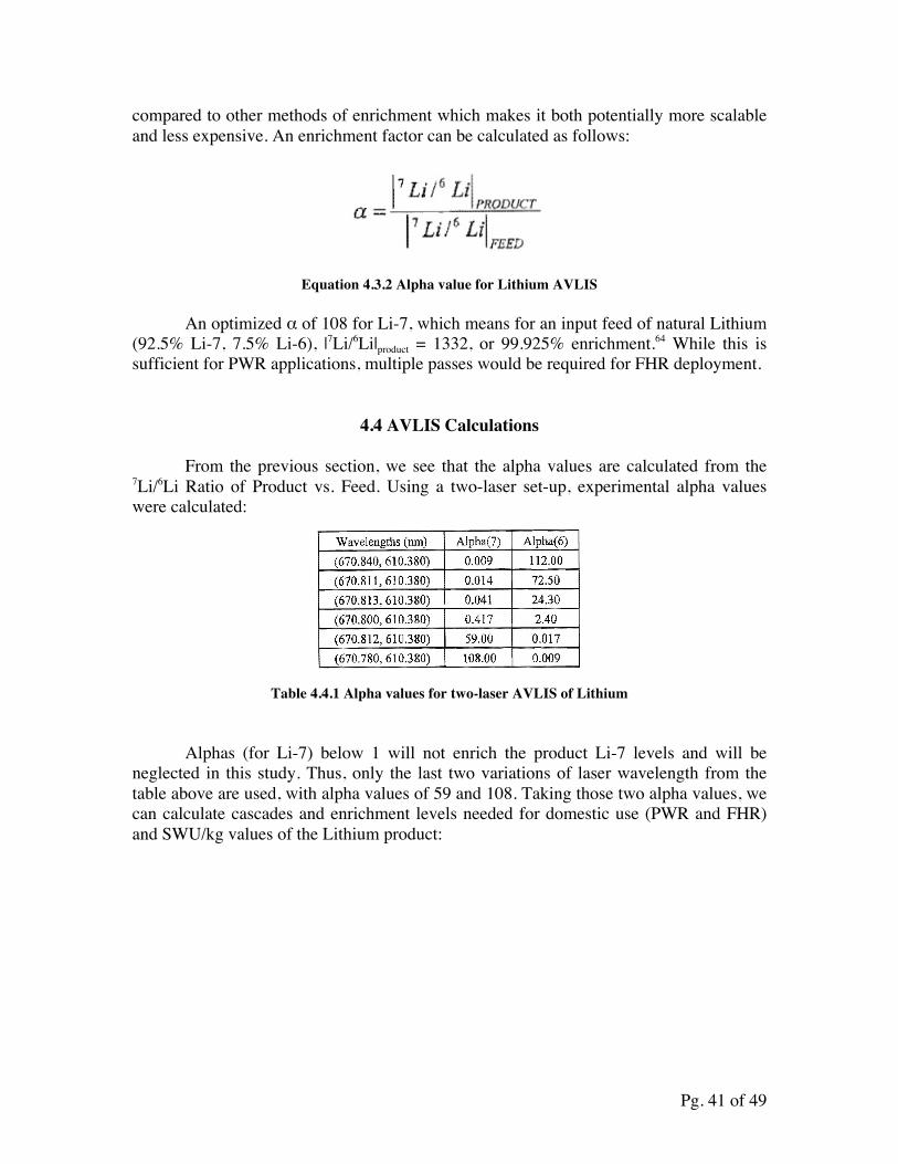
Pg. 41 of 49
compared to other methods of enrichment which makes it both potentially more scalable and less expensive. An enrichment factor can be calculated as follows:
Equation 4.3.2 Alpha value for Lithium AVLIS
An optimized α of 108 for Li-7, which means for an input feed of natural Lithium (92.5% Li-7, 7.5% Li-6), |7Li/6Li|product = 1332, or 99.925% enrichment.64 While this is sufficient for PWR applications, multiple passes would be required for FHR deployment.
4.4 AVLIS Calculations
From the previous section, we see that the alpha values are calculated from the 7Li/6Li Ratio of Product vs. Feed. Using a two-laser set-up, experimental alpha values were calculated:
Table 4.4.1 Alpha values for two-laser AVLIS of Lithium
Alphas (for Li-7) below 1 will not enrich the product Li-7 levels and will be neglected in this study. Thus, only the last two variations of laser wavelength from the table above are used, with alpha values of 59 and 108. Taking those two alpha values, we can calculate cascades and enrichment levels needed for domestic use (PWR and FHR) and SWU/kg values of the Lithium product:
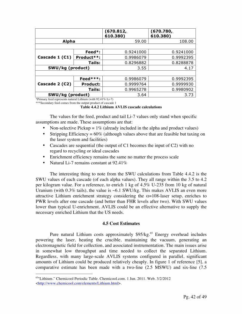
Pg. 42 of 49
(670.812, 610.380)
(670.780, 610.380)
Alpha 59.00 108.00
Cascade 1 (C1) Feed*: 0.9241000 0.9241000
Product**: 0.9986079 0.9992395 Tails: 0.8296882 0.8288878
SWU/kg (product) 3.55 4.17
Cascade 2 (C2) Feed***: 0.9986079 0.9992395 Product: 0.9999764 0.9999930
Tails: 0.9965278 0.9980902 SWU/kg (product) 3.64 3.73
*Primary feed represents natural Lithium (with 92.41% Li-7) ***Secondary feed comes from the output product of cascade 1
Table 4.4.2 Lithium AVLIS cascade calculations
The values for the feed, product and tail Li-7 values only stand when specific assumptions are made. These assumptions are that:
• Non-selective Pickup = 1% (already included in the alpha and product values) • Stripping Efficiency = 60% (although values above that are feasible but taxing on
the laser system and facilities) • Cascades are sequential (the output of C1 becomes the input of C2) with no
regard to recycling or ideal cascades • Enrichment efficiency remains the same no matter the process scale • Natural Li-7 remains constant at 92.41%
The interesting thing to note from the SWU calculations from Table 4.4.2 is the
SWU values of each cascade (of each alpha values). They all range within the 3.5 to 4.2 per kilogram value. For a reference, to enrich 1 kg of 4.5% U-235 from 10 kg of natural Uranium (with 0.3% tails), the value is ~6.1 SWU/kg. This makes AVLIS an even more attractive Lithium enrichment strategy considering the α=108-laser setup, enriches to PWR levels after one cascade (and better than FHR levels after two). With SWU values lower than typical U-enrichment, AVLIS could be an effective alternative to supply the necessary enriched Lithium that the US needs.
4.5 Cost Estimates
Pure natural Lithium costs approximately $95/kg.65 Energy overhead includes powering the laser, heating the crucible, maintaining the vacuum, generating an electromagnetic field for collection, and associated instrumentation. The main issues arise in somewhat low throughput and time needed to collect the separated Lithium. Regardless, with many large-scale AVLIS systems configured in parallel, significant amounts of Lithium could be produced relatively cheaply. In figure 1 of reference [5], a comparative estimate has been made with a two-line (2.5 MSWU) and six-line (7.5 65"Lithium.” Chemicool Periodic Table. Chemicool.com. 1 Jun. 2011. Web. 3/2/2012 <http://www.chemicool.com/elements/Lithium.html>.
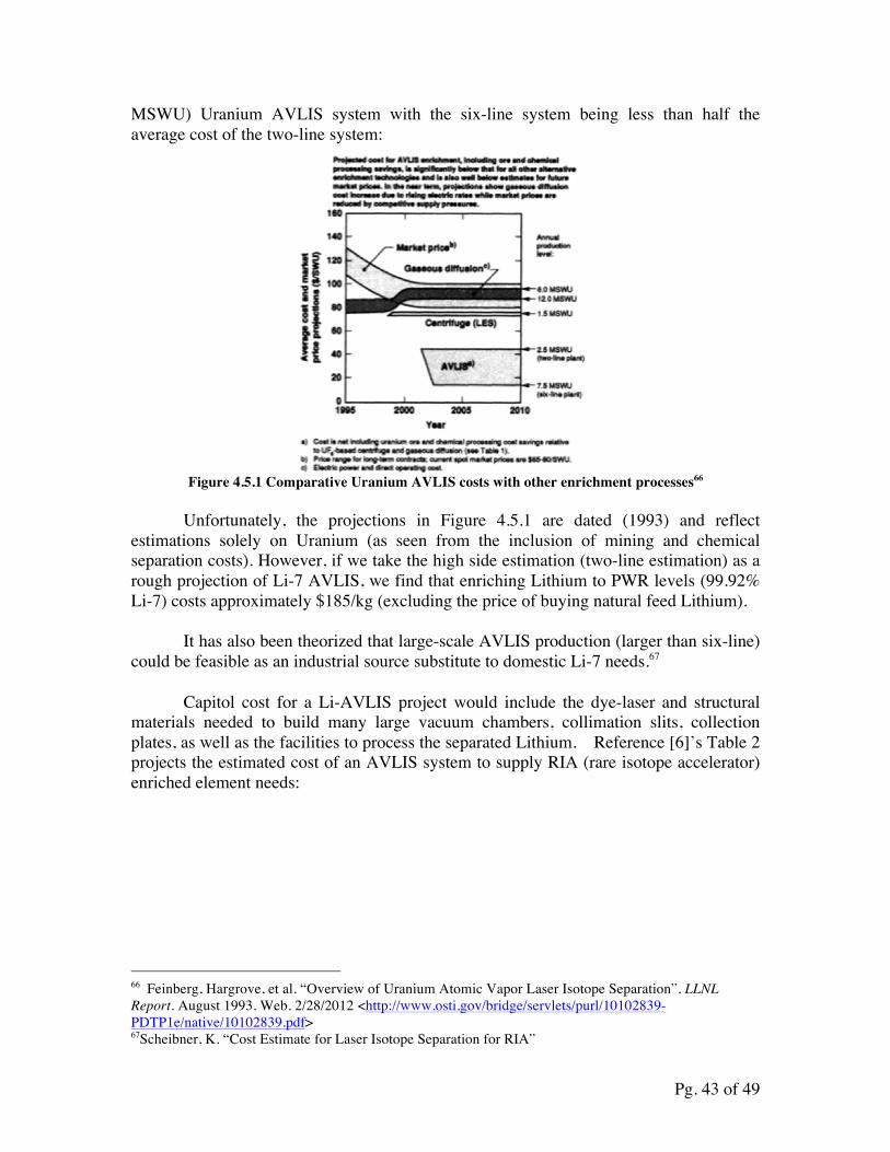
Pg. 43 of 49
MSWU) Uranium AVLIS system with the six-line system being less than half the average cost of the two-line system:
Figure 4.5.1 Comparative Uranium AVLIS costs with other enrichment processes66
Unfortunately, the projections in Figure 4.5.1 are dated (1993) and reflect
estimations solely on Uranium (as seen from the inclusion of mining and chemical separation costs). However, if we take the high side estimation (two-line estimation) as a rough projection of Li-7 AVLIS, we find that enriching Lithium to PWR levels (99.92% Li-7) costs approximately $185/kg (excluding the price of buying natural feed Lithium).
It has also been theorized that large-scale AVLIS production (larger than six-line)
could be feasible as an industrial source substitute to domestic Li-7 needs.67
Capitol cost for a Li-AVLIS project would include the dye-laser and structural materials needed to build many large vacuum chambers, collimation slits, collection plates, as well as the facilities to process the separated Lithium. Reference [6]’s Table 2 projects the estimated cost of an AVLIS system to supply RIA (rare isotope accelerator) enriched element needs:
66 Feinberg, Hargrove, et al. “Overview of Uranium Atomic Vapor Laser Isotope Separation”. LLNL Report. August 1993. Web. 2/28/2012 <http://www.osti.gov/bridge/servlets/purl/10102839-PDTP1e/native/10102839.pdf> 67Scheibner, K. “Cost Estimate for Laser Isotope Separation for RIA”
Pg. 44 of 49
Table 4.5.1 RIA AVLIS Cost projections77
Given the relatively low overheard, AVLIS is an attractive option for Lithium enrichment. An equivalent Calutron (Electromagnetic Separation) facility for RIA needs, would be nearly 5 times as expensive ($92.8 million vs. $17.1 million):
Table 4.5.2 RIA Calutron Cost projections68
Proof of the scalability of the process as well as hard numbers for the overhead energy requirements and capital costs are necessary to determine whether or not this method is truly feasible. Currently, no such extensive study was conducted and/or published for review.
68 Scheibner, K. “Cost Estimate for Laser Isotope Separation for RIA”
Pg. 45 of 49
Though no known extensive studies have been made on Lithium AVLIS costs or SWU, estimates can be derived from studies on Uranium and RIA isotope AVLIS costs. Reference [8], [9], and [10] gives comparisons of various U-enrichment processes with AVLIS estimates which provide a good benchmark for possible cost estimations of Lithium-AVLIS enrichment.
The group recommends an experiment be performed to combine the efforts of Strydom and Scheibner, producing a small scale proof-of-concept of an AVLIS-based Lithium enrichment system. The overall goal would be to experimentally determine realistic numbers for throughput and enrichment level of a scalable AVLIS implementation. Numbers for the non-selective pickup and stripping efficiency of AVLIS when applied to Lithium could aid in understanding how it could be used for other elements as well. With careful choice of the vaporization method and vacuum chamber geometry, we believe that high enough throughputs for commercial production are possible. A hypothetical proof-of-concept system is described as follows. A vacuum chamber is required, capable of a holding the required pressure and a window for the laser. It could be on the order of 1-2 meters tall with several collimation holes inside. The chamber would also need an area for the collector plates and associated electronics. Sheibner measured throughputs ~6g/hour for Pb using another evaporation technique which could be mimicked for this experiment. A generic copper vapor laser, either purchased or assembled in-house, could be used as the pump for the dye lasers. Three dye lasers with the same specifications as Strydom’s could be used for simplicity. Natural Lithium would be purchased put into the vacuum system. After evaporation, ionization and collection, the sample could be sent to a lab for mass spectrometry for confirmation. Aside from the chamber, lasers, and collection plates, a vacuum pump, and power sources would also be required. The overall setup is moderately complicated but the components are relatively simple, hopefully allowing for a small-scale experiment that can provide a clear insight into the effectiveness of using AVLIS for Lithium enrichment.
4.6 Proliferation Concerns
In principle, the AVLIS technique can be used for the enrichment of uranium or procurement of Li-6. It is crucial, for AVLIS to be viable as a means to mass-produce enriched Lithium that the facility is not easily made clandestine. Fortunately several features of AVLIS make it impossible for a Lithium enrichment facility to enrich uranium or produce significant amounts of Li-6 without an inspector immediately noticing. The lasers described in Section 4.2 are very finely tuned and therefore specific to Lithium enrichment. Conveniently, two of the three photons used for ionization have wavelengths in the visible spectrum; any deviation from these colors would be easily detectable by an inspector. The valence electrons of uranium have different binding energies, leading to significantly different excited state energies. This means that lasers of different wavelengths, potentially even outside the visible spectrum, would need to be used. Uranium also has the added complication that it is much more difficult to vaporize than Lithium, requiring extra materials at the enrichment plant not normally needed for
Pg. 46 of 49
Lithium enrichment. It is unclear whether AVLIS for uranium enrichment is even feasible; SILEX (Separation of Isotopes by Laser EXcitation) is a technique using lasers similar to AVLIS, however it is much more complicated than the scheme for enriching Lithium.69
Lithium enriched in Li-6 is used for thermonuclear weapons as a means to produce tritium because of its high thermal neutron 6Li(n,α)3H cross-section. One of the lasers can be slightly altered to selectively ionize Li-6 instead, effectively enriching in Li-6 instead of Li-7. The tails from AVLIS are slightly enriched in Li-6 and could be repeatedly put through cascades for further enrichment as well. However, during the 1954 Bravo test of the Shrimp fusion device, it was discovered that Li-7 has a relatively high fast neutron 7Li(n,α)3H+n cross-section, severely reducing the importance of using enriched Lithium.70 Lithium enriched in Li-6 is therefore not believed to be crucial in the operation of fusion weapons and is unlikely to be the limiting factor in manufacturing a device.
5.0 SUMMARY
As was stated in the initial abstract, it was found that both options (AVLIS and crown ether enrichment) provided results that show promise as alternatives to any mercury-based, COLEX process enrichment. AVLIS is a proven, well-developed process that would adequately provide for the current fleet of domestic PWRs and their demand for highly enriched Li-7. AVLIS does, however, have drawbacks in providing any additional enrichment quantities that are needed for possible FHR deployment. Should the U.S. make the decision to begin construction of FHRs domestically, AVLIS would not be the ideal choice, given FHRs’ great demand for enriched lithium. Instead, crown ether enrichment provides a method of producing the greater Li-7 levels and quantities needed to effectively run FHRs for power generation in the U.S. With China projected to increase their need of enriched Li-7 in the coming years and the U.S. wholly dependent on Chinese suppliers, it is imperative that a policy to diversify enriched lithium sources (particularly domestic sources) be enacted by both the U.S. government and the American utility industry. Utilizing the developed technologies of AVLIS and crown ethers in this regard, would seem like the important decision.
69 Lyman, John L. “Enrichment Separative Capacity for SILEX”. SP-1 POTAS Project, “Enrichment Separative Capacity,” LANL. 2005. LA-UR-05-3786. 70“Operation Castle”. Nuclear Weapon Archive. Nuclearweaponarchive.org. 17 May 2006. Web. 5/4/2012 <http://nuclearweaponarchive.org/Usa/Tests/Castle.html>
Pg. 47 of 49
6.0 REFERENCES
1. Dionex, “Fast and Sensitive Determination of Transition Metals in Power Industry Waters Using Ion Chromatography”, Application Note277, Copyright 2011
2. T. Saario, S. Tähtinen, and J. Piippo, “Effect of Lithium Hydroxide on Stability of Fuel Cladding Oxide Film in Simulated Pressurized Water Reactor Primary Water Environments”, Corrosion, Volume 53, Number 09, September, 1997
3. National Academy of Sciences, “Water and Impurity Activation Products”, Radiation in Nuclear Power Reactors, 1996
4. William R. Kanne Jr. and Robert J. Alexander. “Development of Resistance Welding Methods for Tritium Containment”, WSRC-MS-2000-00061, 2000
5. John Emsley . "Lithium”.. Nature's Building Blocks: An A-Z Guide to the Elements. Oxford, UK: Oxford University Press. p. 239. ISBN 0198503408.2001.
6. D.T. Ingersoll, E.J. Parma, C.W. Forsberg, and J.P. Renier. “Core Physics Characteristics and Issues for the Advance High Temperature Reactor (AHTR)”, Oak Ridge National Laboratory, p. 5
7. M. Ragheb, Isotopic Separation and Enrichment, University of Illinois Urbana-Champaign Course Materials, 2012.
8. David Holcomb, researcher at Oak Ridge National Laboratory, personal communication (email), February 2012
9. John Pike, “Laser Isotope Separation Uranium Enrichment”, Global Security, ed. 2012. http://www.globalsecurity.org/wmd/intro/u-laser.htm
10. WISE Uranium Project, “Uranium Conversion/Enrichment: Current Issues (USA)”. Ed. 2012.http://www.wise-uranium.org/epusa.html
11. Per F. Peterson, professor of Nuclear Engineering at UC Berkeley, personal communication (email), February 2012
12. Nagoya University, “Isotopes for the Prosperous Future: Isotope Separation/Production”. 21st Century COE Program, Updated 2007. http://coe.nucl.nagoya-u.ac.jp/Separation01_E.html
13. Nagoya University, Experimental Apparatus of Displacement Chromatography (Diagram), 2007
14. Klaus G. Heumann, “Isotopic Separation in Systems with Crown Ethers and Cryptands”, Organic Chemistry: Topics in Current Chemistry, 1985, Vol. 127, pp. 77-132 (pp. 120-122)
15. Nishizawa, K. et al. “Extractive Separation of Lithium Isotopes by Crown Ethers”. Separation Science and Technology, 23:4-5, 333-345
16. Chemical Land 21, Prices of Crown Ethers (Table), http://chemicalland21.com/lifescience/phar/15-CROWN-5.htm,
17. Gu, Z, “Lithium Isotope Separation”, Progress in Chemistry, Vol.23, No. 9, Sep. 2011
18. Hu, Jinbo, personal communication, March 2012 19. University of Kentucky, “Flame Photometric Determination of Sodium”,
Chemistry 126: Experiment 8. Jan. 2000. 20. Kenichi Sakata et al., “Inductively Coupled Plasma Mass Spectrometer and
Method”, U.S. patent 6265717 B1.
Pg. 48 of 49
21. Nishizawa, K. et al. “Extractive Separation of Lithium Isotopes Using Crown Ethers, Effect of Salt Concentration”, Separation Science and Technology, 23:6-‐7, 751-‐757
22. Vignes, Robert ."Dimethyl sulfoxide (DMSO) – A "New" clean, unique, superior solvent. "American Chemical Society Annual Meeting” (August 20–24, 2000).
23. Nishizawa K. et. al. “Extractive Separation of Lithium Isotopes by Crown Ethers.” Separation Science and Technology Vol. 23, Iss. 4-5, 1988
24. Nishizawa K. et. al. “Extractive Separation of Lithium Isotopes Using Benzo-15-Crown-5. Effect of Salt Concentration”, Separation Science and technology, 23:6-7, 751-757
25. Ban et. al. “Chromatographic Separation of Lithium Isotopes with Silica Based Monobenzo-15-crown-5 Resin.” Journal of Nuclear Science and Technology. Vol. 39, Iss. 3, 2002.
26. Kim et. al. “Lithium isotope separation on a monobenzo-15-crown-5 resin.” Journal of Radioanalytical and Nuclear Chemistry. 150 (2) (1991). pp. 417–426.
27. “Laboratory Mixer-Settlers.” Rousselet Robatel. Web, 5/5/2012 <http://www.rousselet-robatel.com/products/laboratory-mixer-settlers.php>
28. Benedict, M, Levi, H., Pigford, T. (1981). Nuclear Chemical Engineering. NYC, New York: McGraw Hill.
29. Nishizawa K. et. al. “Lithium Isotope Separation by Liquid-Liquid Extraction Using Benzo15-Crown-5” Journal of Nuclear Science and Technology, 21:9, 694-701
30. “Aqueous Solutions of Lithium and Calcium Chlorides” Conde Engineering, Zurich 2009 http://www.mrc-eng.com/Downloads/Aqueous%20LiCl&CaCl2%20Solution%20Props.pdf
31. “Chemical Compatibility Database” http://www.coleparmer.com/Chemical-Resistance
32. “100m3/h RO brackish water desalination system. “Water Treatment. Alibaba.com. Web 5/4/2012 <http://www.alibaba.com/product-gs/263176797/100m3_h_RO_brackish_water_desalination.html>
33. “LPG Series High Speed Centrifugal Atomizing Spray Dryer.” Drying Equipment. Alibaba.com. Web 5/4/2012 <http://www.alibaba.com/product-gs/350145704/LPG_Series_High_Speed_Centrifugal_Atomizing.html>
34. “ANHYDRO Spray Dryer, Cap. 427 lbs per/hr For Sale Used” Bid-On-Equipment.com. Web 6/10/2012 http://www.bid-on-equipment.com/detail~id~114891.htm
35. “Power Calculator for Generators” www.dieselserviceandsuppli.com. Web 6/10/2012 <www.dieselserviceandsupply.com/Power_Calculator.aspx>
36. Selinger, B. “Facts & Figures: Building Costs” Illinois Department of commerce. www.commerce.state.il.us October 2011, Web 6/10/2012 http://www.commerce.state.il.us/NR/rdonlyres/2E961958-4860-4526-806B-2705C5F42339/0/BuildingCosts.pdf
37. Peters, M. S., Timmerhaus, K. D., West, R. E. (2003). Plant Design and Economics for Chemical Engineers. NYC, New York: McGraw-Hill.
Pg. 49 of 49
38. “Lithium Chloride, 7447-41-8.”Fine Chemical.Alibaba.com. Web. 4/12/2012 <http://srichem.en.alibaba.com/product/476535951-50416318/Lithium_Chloride_7447_41_8.html>
39. “Chloroform.” Organic Intermediate.Alibaba.com. Web. 4/12/2012 <http://www.alibaba.com/product-gs/492259772/Chloroform.html>
40. “Is Water Free.” FCWA. Web. 5/5/2012 <http://www.fcwa.org/story_of_water/html/costs.htm>
41. “Electric Power Monthly.” EIA. Web, 5/5/2012 <http://www.eia.gov/electricity/monthly/epm_table_grapher.cfm?t=epmt_5_6_a>
42. “Laser Isotope Separation Uranium Enrichment”. Globalsecurity.org. <http://www.globalsecurity.org/wmd/intro/u-laser.htm>. 5/5/2012.
43. Strydom, H. J. “Mass Spectrometry Characterization of Laser Produced Products”. Physics Theses. University of Natal. Durban, South Africa. December, 1999.
44. Scheibner, K. “Cost Estimate for Laser Isotope Separation for RIA”. LLNL Report.5 November 2004. Web. 2/27/2012 <https://e-reports-ext.llnl.gov/pdf/313426.pdf>
45. Barnes, Clive. “Copper at the Cutting Edge: The Copper Vapor Laser”. Copper Development Association Inc. www.copper.org. June 2001. <http://www.copper.org/publications/newsletters/innovations/2001/06/cutting_edge.html> . 5/5/2012.
46. “Copper vs. Lithium”. Find the Data: Side-by-Side. Findthedata.org. <http://chemical-elements.findthedata.org/compare/24-51/Copper-vs-Lithium> 5/5/2012.
47. "Lithium.” Chemicool Periodic Table. Chemicool.com. 1 Jun. 2011. Web. 3/2/2012 <http://www.chemicool.com/elements/Lithium.html>.
48. Feinberg, Hargrove, et al. “Overview of Uranium Atomic Vapor Laser Isotope Separation”. LLNL Report. August 1993. Web. 2/28/2012 <http://www.osti.gov/bridge/servlets/purl/10102839-PDTP1e/native/10102839.pdf>
49. Lyman, John L. “Enrichment Separative Capacity for SILEX”. SP-1 POTAS Project, “Enrichment Separative Capacity,” LANL. 2005. LA-UR-05-3786.
50. “Operation Castle”. Nuclear Weapon Archive. Nuclearweaponarchive.org. 17 May 2006. Web. 5/4/2012 <http://nuclearweaponarchive.org/Usa/Tests/Castle.html>


![Medical Isotope Production and Use [March 2009] - National Isotope](https://static.fdocuments.net/doc/165x107/62038cd4da24ad121e4ab7b4/medical-isotope-production-and-use-march-2009-national-isotope.jpg)

