Contemporary Literature 1940 – present An introduction and historical context.

“Studies on Radial Tipped Centrifugal Fan” 22
CHAPTER – 2
LITERATURE REVIEW AND OBJECTIVES OF PRESENT WORK
2.1 Preamble
Turbo – machines are devices in which energy is transferred either to or from, a
continuously flowing fluid by the dynamic action of moving blades of the runner.
Leonardo Da Vinci (1452-1519) was probably the first to coin the idea of lifting
water by centrifugal forces. He has described primitive models of turbomachines by
making some sketches. From his original sketches, a French physicist Denis Papin was
first to describe the centrifugal pump scientifically in 1687. He built first pump in 1705,
which had impeller with blades and a volute. Thus, centrifugal pumps and blowers of
today are made after more than 300 years’ of revolution.
The theoretical treatment of turbo machines requires the knowledge of fluid
dynamics, flow physics and thermodynamics. Spannhake [23] has made pioneering
work in this area and has defined flow physics and associated terminology in his book
entitled “Centrifugal pumps, turbines and propellers” in 1934. His successor Wislieenus
[24] extended his work and documented in “Fluid Mechanics of Turbo machinery” in
1947.
During this period, W. J. Kearton [25] observed breaks in characteristic curves
by carrying accurate tests. His measurements indicated that the flow is far from
uniform, and that on the trailing face of the vane there is an area of “inactive flow”.
This area increases as the capacity is reduced. The effect of this inactive flow is
equivalent to increasing the vane thickness and reducing the passage area. He had
noticed that number of impeller blades has significant effect on fan performance curves.
W. J. Kearton [25] investigated these conditions and has presented his findings in a very
interesting paper, “Influence of the Number of Impeller Blades on the Pressure
Generated in a centrifugal compressor and on its General performance.” He also found
that below the critical flow the velocity distribution was fairly symmetrical and
resembled the velocity distribution obtained with turbulent flow in a pipe. Above the
critical flow the velocity distribution was not symmetrical, but much greater on the side
of the impeller away from the inlet.

Chapter – 2: Literature Review and Objectives of Present Work
“Studies on Radial Tipped Centrifugal Fan” 23
He concluded that overall coefficients based upon experience and test results must be
used until more complete information is available.
Austin H. Church [26] has probably made the first attempt to compile the design
methodology for pumps and blowers. While Eck Bruno [14], Kovats [27], William
Osborne [28], Whitfield and Baines [29] had extended the work of Church and
presented detailed analysis of design parameters for centrifugal, axial and cross flow
fans and blowers. Bela Mishra [30] studied design methodology from literature for
centrifugal blower.
Stodola [31] had developed first useful method for slip factor approximation.
He correlated slip factor and finite number of blades. Stodola claimed that average
direction of discharge varies from the blade angle β2 due to number of blades and
relative circulation in vane to vane plane. This is also responsible for the reduction in
output. Several co-relations as well as empirical equations are used in literature to
estimate slip factor. Other slip factor correlations in literature are given by Balje, Stanitz
[9] and Eck Bruno [14]. According to all these researchers, the major cause of slip are
due to relative eddies generated in vane to vane plane. These correlations conclude that
for a given specified machine, the value of slip factor is constant and is dependent of
Impeller geometry only.
A. J. Stepanoff [32] considers hydraulic losses as the most important and but
least known losses in turbo-machines. He adds that the hydraulic losses are caused by
skin friction and eddies. Separation losses occur due to changes in direction and
magnitude of the velocity of flow. The latter group includes shock loss and diffusion
loss.
D. J. Myles [33] accounts impeller and volute losses as a fraction of the dynamic
exit pressure relative to impeller and volute, respectively. They are correlated with a
diffusion factor over a wide volume flow range. The results are applied to other
impellers and volutes. The low volume flow range of operation is also considered.
Dr. Bruno Eck [14] first dealt with impeller friction or disc friction loss
experimentally. He differentiated impeller loss in to two components as impeller entry
loss and friction loss in impeller. The friction loss in impeller consist retardation and
resultant pressure loss.
William C. Osborne [28] states that the actual performance of a centrifugal fan
(at the design point) differs to the ideal fan power which can be predicted by Euler’s

Chapter – 2: Literature Review and Objectives of Present Work
“Studies on Radial Tipped Centrifugal Fan” 24
equation. This difference can be accounted for inter blade circulation which results in a
reduction of the work done by the impeller. Other factors which contribute to reduction
in output are internal volumetric leakage and pressure losses within fan assembly.
Mechanical losses also affect fan input power.
J.D. Denton [34] defines loss as ‘any flow feature that reduces efficiency of a
turbo machine’. Further, he categorizes losses as profile loss, secondary loss (End wall
loss) and tip leakage loss as major source of turbo machine losses.
Baines and Whitfield [29] states that the governing equations of continuity,
momentum and energy together constitute a set of partial differential equations which
must be solved across the complete domain for which a prediction of the flow field is
required. Various flow phenomenons occurring inside turbomachine can be numerically
analyzed.
P. J. Roache [35] made quantification of uncertainty in computational fluid
dynamics. His review covers verification, validation and confirmation for
computational fluid dynamics (CFD). It includes error taxonomies, error estimation,
convergence rates, surrogate estimators, nonlinear dynamics, and error estimation for
grid adaptation.
Hsin-Hua Tsuei, Kerry Oliphant and David Japikse [36] have developed method
for rapid CFD modeling for turbo machinery. Their study sensibly guides engineers in
the economical and accurate utilization of their CFD tools. A base for rapid calculations
is established and developed easy-to-use CFD analysis as a base for advanced design
development.
At present, with the help of commercially available CFD softwares, any realistic
flow simulation on a three-dimensional basis is allowing designer to estimate influence
of spatial parameters on performance of the machine before experimental evaluation.
The very basic objective of this work is to propose a streamlined design
methodology for a centrifugal fan to offer highest possible energy efficiency for fume
extraction in SDS-9 texturising machines of a medium scale textile industry.
This objective cannot be achieved without clear understanding of influence of
finite number of blades on fan performance, study of available design methodologies,
slip, fan losses and flow physics through published literature and accordingly the
subsequent sections of this chapter deals with these aspects in more detail.

Chapter – 2: Literature Review and Objectives of Present Work
“Studies on Radial Tipped Centrifugal Fan” 25
2.2 Parametric Influence, Performance and Design Methodologies
Few typical studies pertaining to parametric influence, performance and design
methodologies of centrifugal machines are briefly presented here in.
Balje O. E. [6] has observed that optimum efficiency of a centrifugal
blower/fan occurred for slightly backward leaning vanes.
Wosika L. R. [37] experimentally verified that radial and backward leaning
vanes give slightly better efficiencies than forward vanes.
Faulders C. R. [38] proved by experiments that cross flow occurs in vaned
diffuser passages from the suction face of a vane to the pressure face of the next vane.
He further showed that this cross flow can be reduced by increasing the number of
vanes and increasing the radius of curvature of vanes.
Leslie Young and R. A. Nixon [39] concluded that standardized test
arrangement can give useful performance comparison of different pumps working under
standard conditions, but it does not necessarily give a true indication of performance in
service at off design conditions.
Austin Church [26] has done pioneering work to establish design methodology
for pumps, fans and blowers. He found that the type of flow existing in a pump or
blower is always turbulent, it means, the Reynolds number is always well above the
critical value. The flow is seriously disturbed with a resultant loss of head. He has
presented his design with stage compressibility effect, pressure ratio and energy
transfer. He has also considered density changes at various flow sections with respect to
change in temperature and pressure. Thus volume flow rate gets changed continuously.
The dimensions of the air passage are calculated in accordance to this variation in
volume flow. Stage pressure ratio between atmosphere to inlet eye, inlet eye to impeller
inlet, impeller inlet to impeller outlet and impeller outlet to casing outlet are calculated
individually.
Energy transfer by impeller=
∴ Total adiabatic head across the impeller 0.286⁄ . 1
Overall head to be developed by the centrifugal impeller by energy transfer is:
∆∆ 1 1 1 1

Chapter – 2: Literature Review and Objectives of Present Work
“Studies on Radial Tipped Centrifugal Fan” 26
K' is overall pressure coefficient which is used on account of the friction and
turbulence occurring in the impeller. Church has found value of K' = 0.5 to 0.65 by
experiments.
Design of volute casing:
The width of volute casing b3 is taken as 2 to 3 times width of impeller at exit
bv = b3 = 2 to 3b2
Volute base circle/inlet radius r3 is kept slightly higher than r2. In determining cross sectional area of the volute at any point, the problem
consists in finding the area of the section that will pass the volume Qф/360 with a
velocity Vu×R = C. If friction is neglected, the flow through the differential section is:
dQф =b×dr×C/r
The total flow past the section becomes:
ф
360
Vave at 360 º = V4
Radius of volute at angle 360º = r4
Radius of volute tongue r 1.075r
Volute tongue angle θ 132 log⁄
tan Church, 1962
Leakage loss 0.03
Blade Profile:
Blade Profile can be made by tangent of circular arc method or by polar
coordinates method. It is observed that the flow of air through the blade passage of a
centrifugal fan is often far from ideal, and the object of design of blade curvature should
be to provide the minimum of flow separation.
When tangent of circular arc method is used, the impeller is divided into a
number of assumed concentric rings, not necessarily equally spaced between inner and
outer radii. The radius Rb of the arc is defining the blade shape between inner and outer
radii as shown in Figure 2.1.
2 cos cos

Figure
Wh
are calcula
shown in F
Fig
Pec
plotted grap
derived ma
cited that in
e 2.1 Blade
en polar co
ated by usin
igure 2.2.
ure 2.2 Bla
ck J. F. [40
phs of dime
athematical
nternal hydr
“Studies
Profile Con
oordinates m
ng the equa
ade Profile
0] made pre
ensionless p
equations t
raulic losses
Chapter – 2
on Radial Tip
nstructions [26
method is us
ation as foll
Constructi[26
eliminary fa
parameters v
o make com
s are related
: Literature R
pped Centrifug
s by Tange6] sed, points
lowing and
ions by Pol6] an design fo
versus speci
mputer prog
d to Reynold
Review and Ob
gal Fan”
nt of Circu
on the surfa
d plotted as
lar Coordin
or importan
ific speed ta
gram in For
ds number,
bjectives of P
ular Arc M
face of the b
polar coor
nates Meth
nt parameter
aking at bas
rtran IV lan
relative rou
resent Work
27
ethod
blade/vane
rdinates as
od
rs. He has
se. He also
guage. He
ughness of

the flow p
dimensions
Mo
between fo
radial vane
Eck
number of
then the gu
in the theo
infinite and
Vel
App
Vel
Figu
on the vel
backward c
blades whil
Figure 2outlet v
passages, e
s.
hamed Ali
orward curv
blower/fan
k Bruno [1
blades on t
uidance of th
oretically o
d finite num
ocity coeffi
proximate c
ocity coeffi
ure 2.3 give
ocity triang
curved blad
le the dashe
2.3 Diagramelocity tria
“Studies
external lo
i Esa [20]
ed fans and
n make it ide
4] explain
the transfer
he air becom
obtainable p
mber of blade
icient given
calculation t
icient,
es a qualita
gles for the
des. The ful
ed-line trian
ms showingangles for w
Chapter – 2
on Radial Tip
osses, effic
found that
d backward
eal for hand
ned the mag
of energy.
mes less ef
pressure. Th
es is known
n by Eck Bru
to find veloc
ative picture
e three mo
l-line triang
ngles are val
g the effectsward-curve
blades
: Literature R
pped Centrifug
iencies, ho
t radial blad
curved fan
dling dust or
gnitude of t
If the blade
ffective. Thi
he ratio of
n as velocity
uno,
city coeffici
e of the effe
st importan
gles are app
lid for a fini
s of a finited, radial-tis [14]
Review and Ob
gal Fan”
orsepower
de fan has
s and self c
r grit laden
the influenc
es are separ
is causes a
f change in
y coefficient
ient is given
ects of a fin
nt cases of
plicable to a
ite number o
e number oipped and b
bjectives of P
and Impel
characteris
cleaning pro
air.
ce exerted b
rated and m
subsequent
n pressure h
t.
n by Stodol
nite number
f forward, r
an infinite n
of blades.
of blades upbackward-c
resent Work
28
ller outlet
stics lying
operties of
by a finite
made finite,
reduction
head with
a as:
r of blades
radial and
number of
pon the curved

Chapter – 2: Literature Review and Objectives of Present Work
“Studies on Radial Tipped Centrifugal Fan” 29
The practical effect of a finite number of blades can be readily interpreted from
these diagrams as following:
• The relative discharge angle β3 is less than the blade angle β2 in each case.
• The average relative discharge velocity changes, in the case of backward
curved and radial tipped blades it increases and with forward curved blades
decreases.
• In each case, the average absolute discharge velocity C3 is more acute than C2.
• In each case the angle α3 of the absolute velocity is more acute than α2
(important for the construction of guide mechanisms, it means guide vanes and
others)
Most efforts to determine the optimum number of blades have resulted in only
empirical relations. Some of them are given below:
ECK Bruno [14] has recommended the following relation,
8.5 β2 / 1 1/ 2
This formula gives an approximate indication of number of blades required for
normal radial impellers. Further he states that the optimum number of blades of a radial
impeller can only be truly ascertained by experiments.
The number of blades in a centrifugal fan varies from 2 to 64 depending on the
application, type and size. Less number of blades is not able to fully impose their
geometry on the flow and the average direction of discharge varies from the blade angle
β2, where as too many of them restrict the flow passage and leads to higher losses.
Pfleiaderer [9] has recommended:
6.5 2 1 / 2 1 β1 β2 /2
Stepanoff (Stepanoff, 1962) has suggested that,
1/3 β2 ---------- (For smaller sized fans, the number of blades is
less than that suggested by Stepanoff method.)
During his further course of study, he considered design of impeller as utmost
important. The main design objective is the design of an individual fan for specific
requirements. Prior to designing an impeller, the designer should select the shape of the
impeller according to the specific requirements. Various design parameters for impeller
design are considered as following:

Chapter – 2: Literature Review and Objectives of Present Work
“Studies on Radial Tipped Centrifugal Fan” 30
A. Optimum entry and exit breadth b1 and b2
The factors involved in determining the size of the axial breadth b1 of a blade
entry can be readily obtained. Before the introduction of air into the impeller, the air
must be turned through an angle of 90° from the axis of the suction of the intake duct.
This is analogous to a change of direction occurring at a bend. To avoid this detrimental
influence upon the impeller, separation of flow at the bend must be prevented. The most
effective measure to combat separation at this point is to accelerate the main stream.
Therefore the impeller entry area πd1b1, must be smaller than the intake
opening . This change in area will be designated by ξ,
where F1 is the axial intake area and F1' is the impeller ring entrance area. On
account of a reduction in area caused by a hub of diameter do, then
/ 4 1
Where ξ = 1.2: do = hub diameter. Hence,
B. Entry and exit blades angle β1 and β2
For a given volume V and angular velocity ω, at the rotational speed n, with a
fixed value for d1, a minimum velocity w1 will be obtained.
4 /60 1 ⁄
4 /60 1 sin
The minimum value of w1 as a function of the angle β1 is obtained by equating
(dw13/dβ1) =0. Calculation yields the simple result
tan1
√2
The exit angle β2 will be decided by the computer program, based on maximum
efficiency.
C. Ratio of entry and exit diameter: d1/d2
The ratio of entry and exit diameters d1/d2 can be expressed as follows:

Chapter – 2: Literature Review and Objectives of Present Work
“Studies on Radial Tipped Centrifugal Fan” 31
/1 tan
Where t = thickness of blades.
D. The radius of curvature Rb
The radius of curvature of blade Rb is calculated from the following formula:
2 cos sin
Wallace [41] studied and said that for a wide range of positive and negative pre
whirl, it is found that stable operations can be extended to low flow rates by
introduction of positive pre whirl.
R. Subramanian [42] mentioned that the sharpness of the blades at entrance
and the roughness number of the blade surface contributes heavily to the vortex noise.
The blade shape is usually obtained by the approximate single arc method. Design of
blade profile by using point to point method will result in a streamlined flow and less
likelihood of separation at the trailing edge of the blades will occur.
Robert Kazar and John Lynch [43] presented CF fan design for energy
conservation with balancing economic considerations.
S. Sundaram [44] observed that the optimization of number of blades of
centrifugal fan impeller involves a maximization problem of multivariable function with
fluid dynamic constraints. Experimental data based on a simple variation in blade
number alone, keeping other parameters constant, will not yield optimum blade
numbers for a global maximum hydraulic efficiency.
Sankaran and Gopalkrishna [45] found that the absolute velocity is not
uniform near the entrance of the impeller but it is affected by the geometry of the
rotating vanes.
Yadav and Yahya [46] have studied flow visualization and the effect of tongue
area on the performance of the volute casings of centrifugal machines with a swirling
flow free from jets and wakes at their inlet. The flow visualization studies by wool tuft
movements were conducted in the volute channel as well as in the exit diffuser. Flow
separation was observed at high inlet swirl angles near the volute tongue as well as in
the exit diffuser. It was found that the volute performance was strongly dependent on
the tongue area at low and high inlet swirl angles. There is an appreciable pressure

Chapter – 2: Literature Review and Objectives of Present Work
“Studies on Radial Tipped Centrifugal Fan” 32
recovery in the radial direction of volute but it is negligible in the tangential direction.
The average velocity in the tangential directions is not constant.
Sane and Shevare [47] dealt with the design of radial impeller through the
superposition of two flows. The first being the flow in an impeller with the infinite
number of blades, obtained directly as a solution of Navier Stoke’s equations for axi-
symmetric, incompressible and inviscid flow. The second being a potential perturbation
due to finite number of blades with the first flow as the onset flow.
Patel, Patel and Shah [48] presented the method, which gives the range of
design constants and rapid selection for optimum design. The specified design method
is wide enough to cover the complete range of centrifugal pumps. The method can be
easily computerized. The actual test performance of pumps designed by this method lies
within acceptance limits.
William C. Osborne [28] has made very good attempt to use simple flow
physics to design fans/blowers. He has used empirical relations for eye velocity,
meridian velocity and casing velocity with respect to impeller tip peripheral velocity.
Relative velocity is considered same for inlet and outlet conditions. This is one of the
major limitations of this design. Suction, impeller, volute pressure losses and leakage
losses are calculated separately. He said that the purpose of fan is to move air/gas
continuously against moderate pressures. Although, a little compression may occur, it is
customary to consider fan as incompressible fluid machine. Osborne has used circular
arc method to construct centrifugal fan blade profile. Blade profile construction
methodology is described as under.
Blade Profile:
The flow of air through the blade passage of a centrifugal fan impeller is often
far from ideal, and the object of design of blade curvature should be to provide the
minimum of flow separation. This is probably best achieved for backward curved fans
by having blades of aerofoil section working at low angle of attack. However design is
still somewhat empirical.
Most of blade Profiles are generally made by circular arc method. When this
method is used, impeller inlet and exit blade angles and are joined by smooth
curve or straight line. A circular arc is convenient to manufacture and have a simple
geometrical construction as given in Figure 2.4.

j
Fig
Afte
from the ou
to
the inner ci
AB at E. W
justification
The
satisfactory
gure 2.4 Cir
er laying o
uter circle a
OA to cut t
ircle at D. L
With radius
n for this co
e blade prof
y in practice
“Studies
rcular Arc
ut inner an
at an angle
the inner cir
Line AD is n
AE (or DE
onstruction i
file made a
e.
Chapter – 2
on Radial Tip
Method to
nd outer dia
to the r
rcle at C. L
now bisecti
E) the circu
is as follow
as per abov
: Literature R
pped Centrifug
o Construct
ameters of
radius OA,
ine AC (ext
ing at right
ular blade p
w:
ve construct
Review and Ob
gal Fan”
t Fan Blade
the impelle
and line O
tended if ne
angles, the
profile may
tion method
bjectives of P
e Profile [2
er, line AB
OC drawn at
ecessary) wi
bisector me
y now be dr
d appears to
resent Work
33
8]
B is drawn
t an angle
ill also cut
eeting line
rawn. The
o perform

Chapter – 2: Literature Review and Objectives of Present Work
“Studies on Radial Tipped Centrifugal Fan” 34
Sideris and Braembussche [49] presented a set of detailed experimental data
describing the impeller response to a circumferential variation of the outlet pressure.
These data reveals that the outlet volume influences the flow inside the impeller through
the static pressure variation at the impeller exit and signifies the need of re-evaluation of
theoretical prediction methods. It describes the advantages and disadvantages of the
different geometries, the relation between flow and geometry, and the impact on the
downstream or upstream of impeller, the loss mechanisms and some loss prediction
models are presented. The main purpose of this study is to provide an insight into the
flow structure that can be used later to improve the performance or remediate design
problems. The use of CFD is not discussed here but the flow models presented here may
help to get a better understanding of the CFD output.
G. Karadimas [50] made the optimization of rotor and stator aerofoil section
for the assessment of off-design performance, and the operational stability of the fan. In
the recent past, the performance of transonic fans has been significantly improved. In
addition, through the extensive use of advanced aerodynamic computation codes, the
development time required has been considerably reduced. Methods are used for the
definition of airfoils in quasi-three-dimensional flow with boundary layer optimization
to the analysis of three-dimensional inviscid flow for stage operation at the design point
and in off-design conditions. Detail comparison of full-size component test data with
computation results shows the validity of these methods and also identifies those areas
where research is still required.
Kind and Tobin [51] concluded that large values of rotor exit to inlet area ratio
of fans results in separation of the incoming flow. This paper presents the results of
performance measurements of the mean flow field at rotor inlet and rotor exit for three
squirrel-cage fan configurations. The flow-field measurements were taken with a five-
hole probe for total pressure, static pressure, and the three components of velocity.
Measurements were taken for two different casing throat areas and rotors. For each set
of configuration, flow rate was measured in the vicinity of best efficiency point. Flow
patterns are complex and the reverse flow through the rotor blades was observed even at
the best-efficiency operating condition. This was similar to all fan configurations under
study.
Ishida, Ueki and Senoo [52] highlighted secondary flow occurrence.
According to the theory presented by the authors, the tip clearance loss of an un-
shrouded centrifugal impeller mainly consists of two kinds of losses, one is the drag due
Chapter – 2: Literature Review and Objectives of Present Work
“Studies on Radial Tipped Centrifugal Fan” 35
to the leakage flow through the blade tip clearance and the other one is the pressure loss
to support the fluid in the thin annular clearance space between the shroud and the
blade tip against the pressure gradient in the meridional plane without blades. The
former is proportional to the leakage flow or the contraction coefficient of leakage flow.
The authors have conducted performance tests using an impeller with 16 backward-
leaning blades in three blade tip configurations having round edge, sharp square edge,
and edge with an end-plate. The experimental tip clearance effects can be predicted by
assuming reasonable contraction coefficients 0.91, 0.73, and 0.53, respectively. The
impeller efficiency is improved by 1.5% by reducing the contraction coefficient from
0.91 to 0.53, providing that the tip clearance ratio at the exit of impeller is 0.1.
Whitfield [53] illustrates how the initial design can be developed without
recourse to empirical loss models and the associated uncertainties. A fully non-
dimensional preliminary design procedure for a centrifugal compressor is presented.
The procedure can be applied for any desired pressure ratio to develop an initial non-
dimensional skeleton design. The procedure is applied to compressor design for
pressure ratios of 2, 6.5 and 8.
Frost and Nilsen [54] proposed a simple model for estimating the contribution
of the volute to the shut-off head of a centrifugal pump or fan. The model is based on an
assumed linear distribution of tangential velocity in the plane of the cutwater, which
satisfies approximately the continuity condition of zero net flow into the outlet duct.
The contribution of the impeller is assumed to be that given by a solid body rotation at
the angular velocity of the pump from the bore of the inlet duct to the impeller tip. The
simple radial equilibrium equation is then used to calculate the static head rise in both
the impeller and volute. The resultant prediction of shut-off head has been compared to
test data on various pump series made available by courtesy of two European
manufacturers. In all of the series, the impeller diameter has been varied between 100
and 90 to 80 percent of its design value and has been tested in the designed volute.
Since a review of the available literature did not show any previous work of a fully
consistent nature on this topic, the proposed model as described in detail is offered as a
fairly accurate prediction technique for design purposes.
Al-Zubaidy [55] described a scheme for computer aided design and
manufacture of radial impeller. It is starting with one-dimensional calculations. The
principle dimensions (for given performance requirements) are optimized using a
suitable optimization algorithm.

Chapter – 2: Literature Review and Objectives of Present Work
“Studies on Radial Tipped Centrifugal Fan” 36
Y. Chon, K. I. Kim and K. Kim [56] attempted to design the optimal
centrifugal fan with specific given conditions by using a knowledge based system which
relies on practical experience in the form of knowledge data base rather than
mathematical representation.
Figure 2.5 gives design algorithm proposed by them.
Figure 2.5 Fan Design Process Algorithms [56]
There are a huge number of possible output answers for one piece of input data.
However, this simulation study demonstrates the optimal answers for different design
conditions and input variables.
For the design, comparison, and critical assessment of all fans, pressure
coefficient, volume coefficient, speed coefficient, diameter coefficient, and noise

Chapter – 2: Literature Review and Objectives of Present Work
“Studies on Radial Tipped Centrifugal Fan” 37
coefficient have been used as dimensionless coefficients. To get optimum design, a
precise knowledge of losses is of interest for many reasons. Each individual rule set was
combined with the others in the rule base by the inference engine. This inference engine
serves as the control mechanism for the knowledge-based system. It is an essential part
of the knowledge-based system, as well as a major factor in determining the
effectiveness and efficiency of the system. A simulation study demonstrates the
effectiveness of the proposed approach. Though the design has been expressed in a
mathematical form, the results deviate greatly from the experimental results.
Ayder, Braembussche and Brasz [57] said that static pressure distribution
depends on the relative centrifugal forces due to the swirl velocity in the cross section.
Detailed measurements of the swirling flow in a centrifugal compressor volute with
elliptical cross section are presented. They show important variations of the swirl and
through flow velocity, total and static pressure distribution at the different volute cross
sections and at the diffuser exit. The basic mechanism defining the complex three
dimensional flow structures are clarified. The different sources of pressure loss have
been investigated and used to improve the prediction capability of one-dimensional
mean streamline analysis correlations. The tangential flow loss model under
decelerating flow conditions and the friction loss model are confirmed. New empirical
loss coefficients are proposed for the exit cone loss model and the tangential flow loss
model for the case of accelerating flow in the volute.
Pinarbasi and Johnson [58] derived that as the flow progresses through the
impeller, variations in the tangential direction mixes out, but variations in the axial
direction tends to persist. Hot-wire anemometer measurements have been made in the
vane less diffuser of a 1 meter diameter low-speed backswept centrifugal compressor
using a phase lock loop technique. Radial, tangential, and axial velocity measurements
have been made on eight measurement planes through the diffuser. The flow field at the
diffuser entry clearly shows the impeller jet-wake flow pattern and the blade wakes. The
passage wake is located on the shroud side of the diffuser and mixes out slowly as the
flow moves through the diffuser. The blade wakes, on the other hand, distort and mix
out rapidly in the diffuser. Contours of turbulent kinetic energy are also presented on
each of the measurement stations, from which the regions of turbulent mixing can be
deduced.
S. Yedidiah [59] discussed the present state of the knowledge of the manner in
which the impeller geometry affects the development of head. A comparison with the

Chapter – 2: Literature Review and Objectives of Present Work
“Studies on Radial Tipped Centrifugal Fan” 38
test results is a very impressive agreement between theory and practice. This paper
discusses the practical significance of the recent finding that the amount of liquid which
is directly affected by a blade appears to be of the same order of magnitude as the
volume which the blade is displacing. The paper discusses, primarily, causes related to
roto-dynamic pumps, but it is emphasized that this finding is also applicable to a wide
spectrum of additional disciplines.
Mishra Bela [30] critically studied the design methodology as suggested by
Eck Bruno [14] and traced out radial tipped centrifugal blower design methodology.
R. J. Kind [60] describes a method for predicting flow behavior and
performance for centrifugal fans of the squirrel-cage type. Measurements have been
made in an automotive HVAC blower having two different centrifugal fans. This work
is intended to improve the performance of a conventional forward-curved centrifugal
fan. Mean velocities and pressure have been measured using a miniature five-hole probe
and a pressure scanning unit connected to an online data acquisition system. The
measurements showed that performance coefficients are strongly influenced by flow
characteristics at the throat region. Fan performance curves are showing a significant
attenuation of unstable nature achieved with the new fan rotor in the surging operation
range. Based on the measured results, design improvements were carried out.
Dilin, Sakai, Wilson and Whitfield [61] made a detailed experimental study at
the Science University of Tokyo for the performance of two radial-flow fan. This study
includes a volute with a full tongue (such that no recirculation flow occurs) and the
same volute but with the tongue cut back to allow flow recirculation. Velocity and
pressure distributions at a wide range of azimuth angles were obtained experimentally
and are presented. At the University of Bath, a computational model, using the k-έ
turbulence model, has been presented to predict the internal flow in both volutes with
particular attention given to the tongue flow. Predicted flow separation by CFD at the
volute tongue has been demonstrated experimentally by laser sheet studies at the
Science University of Tokyo. The performance of the volutes is discussed and the
computational fluid dynamics (CFD) analysis is used to recommend design
improvements for the volute.
H. W. Oh and M. K. Chung [62] said that usual iterative cut-and-try design
process can be avoided by simply assigning the weighting factors in the range between
0 and 1. Designer can easily find the optimum values of the design variables to meet
their particular requirements of centrifugal pump design. The optimized geometric and
Chapter – 2: Literature Review and Objectives of Present Work
“Studies on Radial Tipped Centrifugal Fan” 39
fluid dynamic design curves as functions of the non-dimensional specific speed are
presented. An optimal design code for centrifugal pumps has been developed to
determine the geometric and fluid dynamic variables under appropriate design
constraints. The optimization problem has been formulated with a non-linear objective
function to minimize one, two or all of the fluid dynamic losses. The optimal solution is
obtained by means of the Hooke-Jeeves direct search method. The performance analysis
is based on the mean streamline analysis using the present state-of-the-art loss
correlations. The optimized efficiency and design variables of centrifugal pumps are
presented in this paper as a function of non-dimensional specific speed in the range of
0.5 ≤ Ns ≤ 1.3. The diagrams presented can be used efficiently in the preliminary design
phase of centrifugal pumps.
S. M. Yahya ([9] expressed that on account of low pressures developed by fan
and blowers, they are separate class of turbomachines. They must be designed
separately instead of following compressor or pump design for them. Care must be
taken for Impeller and volute casing design. Energy imparted to the fluid by rotating
impeller will raise its static, stagnation pressure and velocities. The stage work and
stagnation pressure rise for a given impeller depend on the whirl or swirl components
(Vu1 and Vu2) of absolute velocity vectors V1 and V2, respectively. Following relations
are used to find out different stage parameters. The mass flow through the impeller is
ρ1 1 ρ2 2
The area of cross section normal to the radial velocity components
A1 = π d1 b1 and A2 = π d2 b2
Therefore m = ρ1 Vr1 ("π"d1 b1) = ρ2 Vr2 ("π"d2 b2)
The stage work is given by the Euler’s equation as
Wst = U2 VU2 - U1 VU1
In the absence of inlet guide vanes, it is reasonable to assume zero whirls at the
entry. This condition gives,
α = 90° so VU1 = 0 hence U1 VU1 = 0
∴ Wst = U2 VU2
The power required to drive the fan is
P = m (Δho)st = m Cp (ΔTo)st = m U2 VU2
Stage pressure rise
(Δpo)st = (p2 -p1) + 1/2 ρ (V22 - V1
2) = po2 - po1

Chapter – 2: Literature Review and Objectives of Present Work
“Studies on Radial Tipped Centrifugal Fan” 40
The stage pressure coefficient
ψst = (Δpo)st /1/2 ρ U22 = 2(VU2 / U2)
The degree of reaction in fan stage is,
Δ / Δ
Where (Δp)rotor = 1/2 ρ (U22 - W2
2 + Vr22)
∴ Rr = 1 - 1/2 VU2 / U2
For radial tipped blades VU2 = U2
∴ Rr = 1/2
Stage efficiency ηst = (Δpo)st / ρ U2 VU2
Static pressure is recovered from the kinetic energy of the flow at the impeller
exit by diffusing the flow in a vaneless or vaned diffuser. The spiral casing as a
collector of flow from the impeller or the diffuser is an essential part of the centrifugal
fan and blower. Diffusers are usually employed on blowers with high heads whereas
volutes are commonly used for fans developing low heads. A diffuser or volute casing
operates on the principle of increasing the pressure energy by decreasing kinetic energy
of flow by diffusing this flow in a vane less or vaned space. A partial increase in head
occurs in the diffuser, surrounding the impeller.
Centrifugal fan with vaned diffuser can give slightly higher efficiency compared
to vaneless fan diffuser/volute casing. For majority of centrifugal fans and low pressure
blowers, the higher cost and size that result by employing a vaned diffuser outweigh its
advantages.
Theoretically, the logarithmatic curve of volute casing begins at the impeller
exit, but in practice this is not possible due to sharp edged lip at base circle of casing,
known as the tongue will be formed. Tongue edge is kept blunt and shifted to reduce
shock losses and improve volute performance.
The volute or scroll casing (in the absence of a diffuser) collects and guides the
flow from the impeller to exit. The volute base circle radius is little larger (0.05 to 0.10
times the impeller exit radius) than the impeller or diffuser exit radius. The vane less
space before volute decreases the non-uniformities and turbulence of flow entering the
volute as well as reduces noise level.
The cross-section of the volute passage may be square, rectangular, circular or
trapezoidal. The fabrication of a rectangular volute from sheet metal is simple while
other shapes can be cast. Rectangular section is very common in centrifugal fan and
Chapter – 2: Literature Review and Objectives of Present Work
“Studies on Radial Tipped Centrifugal Fan” 41
circular section is widely used for compressor outlet. Two most widely used volute
design methods are discussed below.
• Free vortex design
Here the flow through the volute passage is assumed to be a free vortex flow.
The axial component of vorticity is zero and angular momentum remains constant.
i.e. rVθ = r2Vθ2 = r3Vθ3 = K
So, Vθ K/r
For constant width of casing for b3 b4, the direction of the streamlines remain
constant, i.e., "tanα Vm/V θ constant"
The total volume flow Q supplied by the impeller is uniformly divided at the
volute base circle. Therefore the flow rate at any section of the volute passage, θ degree
away from the starting is,
Qθ = (θ/360) Q
The flow rate through an infinitesimal section of cross section (dr × b) is,
dQθ = Vθ b3 dr
or dQθ = K b3 dr/r
For the full cross section of the volute passage,
θ
So, / θ/360 /
For a rectangular cross section, it is required to determine the radius r4 of the
volute boundary from θ = 0o to θ = 360o
i.e. θ/360 /
• Constant mean velocity design
For obtaining high efficiency, it is necessary to maintain constant velocity of the
fluid in the volute passage at the design point. This would also give uniform static
pressure distribution around the impeller.
In actual practice, the velocity and pressure vary across the cross section of the
volute passage at any given section. So the mean velocity and pressure along the volute
passage are assumed to remain constant.
For a given value of the mean velocity (Vm), the area distribution is obtained as,
Qθ = Vm Aθ = (θ /360) Q
Aθ = (θ /360) ( Q/ Vm)
Chapter – 2: Literature Review and Objectives of Present Work
“Studies on Radial Tipped Centrifugal Fan” 42
For a rectangular cross section,
Aθ = b3 (r4 - r3)
Thus the volute radius r4 for given values of r3 and b3 can be determined.
However, this assumption will be violated at the off-design point. Hence free vortex
design theory is preferable for volute casing.
D. V. Bhopea, P. M. Padoleb [63] made stress analysis of fan impeller by
experimental and finite element method. It has shown that the stress pattern in impeller
components is highly complex. The stresses in the impeller components can be reduced,
by using the stiffening rings on the blades. The flow of centrifugal fan has been also
determined by using the set-up as per AMCA and NAFM guidelines. The effect of the
stiffening rings on the stresses, noise and fluid flow has been also investigated and
discussed.
Tahsin Engin, Mesut Gur, Reinhard Scholz [64] studied that centrifugal fan
when handling gases with temperatures exceeding 800 °C, the conventional steel
impellers would not be operated at such elevated temperatures. In their experimental
study, three semi-open centrifugal fan impellers have been designed and fabricated
using ceramic materials to provide high resistance to temperature. Experiments have
been conducted to investigate the performance characteristics of these impellers and the
deteriorations in their performance due to varying tip clearance. Factors have been
determined to estimate the tip clearance losses. Results showed that the simple impeller
geometries of ceramic materials were less sensitive to the varying tip clearance. In
addition, the gas temperature has been found to have almost no influence on the
performance degradation due to the tip leakage flow.
By studying three dimensional flow fields, it has been deduced that the impeller
with backward-curved blades was very sensitive to the tip clearance, whereas the other
two types were not. The impeller with radial tipped blades 90° showed a weak
dependency on tip clearance. However, for the case of fully radial blades
90° , it has been observed that the fan is almost insensitive to the tip clearance.
However, considerable flow separations have been observed at even in design flow
rates in the blade and scroll passages of this type impeller. The non-uniformity of the
flow field in each fan passages differs considerably from each other and intensifies
particularly near the cut-off regions.

Chapter – 2: Literature Review and Objectives of Present Work
“Studies on Radial Tipped Centrifugal Fan” 43
Yu-Tai Lee and et al, [65] presented a design method for re-designing the
double-discharge, double-width, double-inlet (DWDI) centrifugal impeller for the lift
fans of a hovercraft. Given the current high performance of impellers, the design
strategy uses a computational method, which is capable of predicting flow separation
and vortex-dominated flow fields, enabling a detailed comparison of all aerodynamic
losses. The design method, assuming a weak interaction between the impeller and the
volute, employs a blade optimization procedure and several effective flow path
modifications. Simplified CFD calculations were performed on fans with two existing
impellers and the newly designed impeller to evaluate the impeller design criterion. The
calculation was made with the impeller/volute coupling calculation and a frozen
impeller assumption. Further refined CFD calculations, including the gap between the
stationary bell-mouth and the rotating shroud, revealed a reduction in the new impeller's
gain in efficiency due to the gap. The calculations also further supported the necessity
of matching the volute and the impeller to improve the fan's overall efficiency.
Measured data of three fans validated CFD predictions in pressure rise at design and
off-design conditions. CFD calculations also demonstrated the Reynolds number effect
between the model- and full-scale fans. Power reduction data were compared between
the measurements and the predictions along with the original design requirements.
O. P. Singh, Rakesh Khilwani, T. Sreenivasulu, M. Kannan [66] investigated
effect of geometric parameters of a centrifugal fan with backward- and forward-curved
blades. Centrifugal fans are used for enhancing the heat dissipation from the IC engine
surfaces. In the process, the fan consumes power generated from the engine. As a first
step, an experimental setup was developed and prototypes of fans were made to carry
out measurements of flow and power consumed by the fan. The fan mounting setup was
such that fan with uniform blades can be tested. Generally, fans have cut blades on the
vehicle due to mounting accessories. Next, a computational fluid dynamics (CFD)
model was developed for the above setup and the results are validated with the
experimental measurement. Further, parametric studies were carried out to quantify the
power coefficient, flow coefficient, efficiency and flow coefficients formulated as
below:
2 2 /30
/30

Chapter – 2: Literature Review and Objectives of Present Work
“Studies on Radial Tipped Centrifugal Fan” 44
The parameters considered in this study are number of blades, outlet angle and
diameter ratio. Figure 2.6 shows backward curved blade fan showing how blades are cut
due to mounting accessories and a line diagram depicting fan parameters.
Figure 2.6 Backward Curved Blade Fan Showing how Blades are Cut Due to Mounting Accessories and a Line Diagram Depicting Fan Parameters
[66]
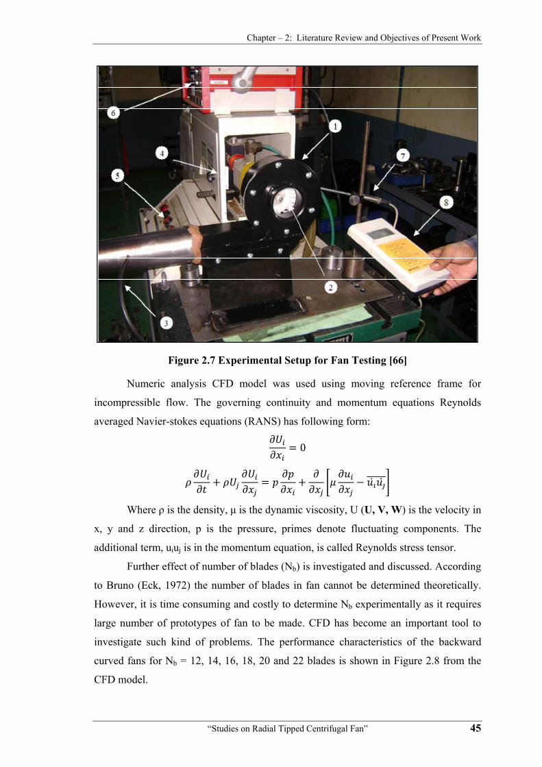
Figure 2.7 shows developed experimental setup for fan testing. The numbers in
the Figure denotes: (1) volute casing, (2) fan (3) tube connected from volute outlet to
the U-tube manometer, (4) low friction torque measurement machine (5) RPM control
switch, (6) torque value displayer unit (7) optical sensor to measure rpm (8) digital
meter for rpm display.
Chapter – 2: Literature Review and Objectives of Present Work
“Studies on Radial Tipped Centrifugal Fan” 45
Figure 2.7 Experimental Setup for Fan Testing [66]
Numeric analysis CFD model was used using moving reference frame for
incompressible flow. The governing continuity and momentum equations Reynolds
averaged Navier-stokes equations (RANS) has following form:
0
Where ρ is the density, μ is the dynamic viscosity, U (U, V, W) is the velocity in
x, y and z direction, p is the pressure, primes denote fluctuating components. The
additional term, uiuj is in the momentum equation, is called Reynolds stress tensor.
Further effect of number of blades (Nb) is investigated and discussed. According
to Bruno (Eck, 1972) the number of blades in fan cannot be determined theoretically.
However, it is time consuming and costly to determine Nb experimentally as it requires
large number of prototypes of fan to be made. CFD has become an important tool to
investigate such kind of problems. The performance characteristics of the backward
curved fans for Nb = 12, 14, 16, 18, 20 and 22 blades is shown in Figure 2.8 from the
CFD model.

Chapter – 2: Literature Review and Objectives of Present Work
“Studies on Radial Tipped Centrifugal Fan” 46
Figure 2.8 Performance Characteristics for 12 to 22 Blades [66]
Other fan parameters were kept constant. The main purpose of this discussion is
to provide information about the percentage change in fan performance due to fan
blades alone. From 12 blades to 22 blades, the gain in pressure coefficient, efficiency
and flow coefficient is 4%, 5% and 10.6%, respectively. It is to be noted that from 12 to
22 blades, mass of the fan blades increases about 80% whereas the performance has not
improved proportionally. The relative velocity in the blade passage becomes more
uniform due to proper guidance as Nb increases and hence wakes regions decreases.
This could reduce noise generated due to wake formation. Formation of wake region is
one of the major contributors to the fan losses. Further increase in Nb would deteriorate
the fan performance and boundary layer effects may become dominant.
The results suggest that fan with different blades would show same performance
under high-pressure coefficient. However, the difference between the performances
becomes distinct under low pressure coefficients suggesting that the fan performance
testing should not be done on vehicle level where high pressure coefficients is observed
due to various resistances in the system. The results show that increase in flow
coefficient is accompanied by decrease in efficiency and increase in power coefficient.
Effect on the vehicles mileage due to the use of forward and backward fan is also
discussed. In summary, this study presents a systematic and reliable strategy to
investigate the centrifugal fan performance in automotive applications.

Chapter – 2: Literature Review and Objectives of Present Work
“Studies on Radial Tipped Centrifugal Fan” 47
Li Chunxia, Wang Song Linga, Jia Y akuib [67] investigated the influence of
enlarged impeller in unchanged volute on G4-73 type centrifugal fan performance.
Comparisons are conducted between the fan with original impeller and two larger
impellers with the increments in impeller outlet diameter of 5% and 10%, respectively,
for numerical and experimental investigations. The internal characteristics are obtained
by the numerical simulation, which indicate that there is more volute loss in the fan with
larger impeller. Experimental results show that the flow rate, total pressure rise, shaft
power and sound pressure level have increased, while the efficiency have decreased
when the fan operates with larger impeller. Variation equations on the performance of
the operation points for the fan with enlarged impellers are suggested. Comparisons
between experimental results and the trimming laws show that the trimming laws for
usual situation can predict the performance of the enlarged fan impeller with less error
for higher flow rate, although the situation of application is not in agreement. The noise
frequency analysis shows that higher noise level with the larger impeller fan is caused
by the reduced impeller–volute gap.
Yi Xie [68] evaluated performance of two shroud designs having parabolic and
cone shape of a backward inclined (BI) commercial centrifugal fan. The considered fan
that is produced by Nicotra Company has diameter about 400 mm and 11 blades. Whole
device with inlet and outlet channel was numerically simulated in steady state, with two
shroud shape. Results for parabolic shape were verified by performance curves obtained
by experimental tests done by Nicotra. There is a separation region under shroud
because of rapid flow direction changes, from axial direction in inlet to radial in
entrance of impeller. Performance curves show that parabolic shape has better flow
guidance than cone shaped one especially in the impeller outlet, which results in
reduction in flow losses due to recirculation from this region to inlet clearance. Because
of this treatment pressure generation and efficiency are about 3 to 4% and almost 6.5%
more, respectively, for parabolic shape.
Jason Stafford, Ed Walsh, Vanessa Egan A. [69] recorded the thermal
performance characteristics of a range of geometrically scaled centrifugal fan designs
by using velocity field and local heat transfer measurement techniques. Complex fluid
flow structures and surface heat transfer trends due to centrifugal fans were found to be
common over a wide range of fan aspect ratios (blade height to fan diameter). Using the
fundamental information inferred from local velocity field and heat transfer

Chapter – 2: Literature Review and Objectives of Present Work
“Studies on Radial Tipped Centrifugal Fan” 48
measurements, selection criteria can be determined for both low and high power
practical applications where space restrictions exist.
Sheam-Chyun Lin, Ming-Lun Tsai [70] made investigations for evaluating fan
performance. An 80 mm-diameter backward-inclined centrifugal fan is chosen to serve
as the research subject for demonstration purposes. Numerical results are utilized to
perform detailed flow visualization, torque calculation, efficiency estimation, and noise
analysis. The results indicate that the fan performance curve and the sound pressure
level (SPL) spectrum of the experiment agree with those of numerical simulations. In
addition, this study proposes two modification alternatives based on the flow
visualization at each operating point, having verified the successful enhancement of fan
performance via numerical calculation. Consequently, this study establishes an
integrated aerodynamic, acoustic, and electro-mechanical evaluation scheme that can be
used as an essential tool for fan designers.
Guopeng Liu and Mingsheng Liu [71] developed a simple in-situ fan curve
measurement procedure using the manufacturers fan curve and one point (air flow and
fan head) measurement according to on site conditions and without interrupting normal
system operations. The in-situ method can simplify air flow measurement if the
manufacturers fan curve is available. Fan air flow measurement continues to be
challenging in HVAC systems. The fan performance curve can be represented as a
multiple order polynomial equation. The in-situ method proposed in this paper makes
use of fan performance curves to predict air flow. Under full speed, the fan curve
equation can be represented as a second-order polynomial equation:
· ·
Where H is a fan head [Pa] under full fan speed, Q is an air flow rate [m3/s]
under full fan speed, and a0, a1 and a2 are fan curve coefficients.
Above equation works well at the normal operating region for most of fans used
in AHUs. If the fan runs under partial speed by the variable frequency drive (VFD), the
fan curve can be represented by equations derived by the fan laws.
This paper presents the background theory, methodology, error analysis and
step-by-step procedure developed for the practitioners. This in-situ method has been
experimentally proven in full-scale air handling unit (AHU) systems. The results show
that the fan curve identified using this simplified approach agrees with the fan curve
identified using the point-by-point direct measurement method. Both the error analysis
and the experiment show that the generated in-situ fan curve with least system

Chapter – 2: Literature Review and Objectives of Present Work
“Studies on Radial Tipped Centrifugal Fan” 49
resistance most closely matches the measured in-situ curve (cv-RMSE = 4.7%). The
differences of the fan heads predicted by the fan curves are within the experimental
error range.
Beena D. Baloni, S. A. Channiwala, V. K. Mayavanshi [72] made
experimental study using two different designs of volute casing of a centrifugal blower
with backward blade shrouded impeller. The volute casing designs were based on the
principle of “constant angular momentum” and “constant mean velocity”. For both
design of volute, the flow fields were studied at various angular, radial and axial
locations in the volutes. The experiments were conducted with full throttle open
condition at inlet. Analysis was done with the help of three-dimensional probe, which
gave flow parameters such as stagnation pressure, static pressure and flow directions.
Based on the experimental data, analyzed results were presented for the pressure
recovery coefficient and loss coefficient. Outcome of the work was concluded that the
flow within the volute casing based on ‘‘constant mean velocity’’ design concept gives
better flow conditions than that based on the ‘‘constant angular momentum’’. The
gradient of both the flow parameters were less in case of ‘‘constant mean velocity’’
design, suggests more flow uniformity compared to ‘‘constant angular momentum’’
design concept. Variation in the pressure recovery is larger up to 50% of radial distance
from the impeller towards radial outward direction. Value of loss coefficient was
decreased as flow move from suction to exit of volute.
2.3 Slip Factor
Under actual conditions, the relative flow leaving the impeller of a fan, blower,
pump or compressor will receive less guidance from the vanes and hence real flow is
reduced. This difference in guidance is known as slip. If the impeller could be imagined
as being made with an infinite number of infinitesimally thin vanes, then an ideal flow
would be perfectly guided by the vanes and would leave the impeller at the vane angle.
The concept of slip factor is implied to impeller losses. Slip loss is defined as the
ratio of actual and ideal values of the whirl velocity components at exit of impeller as
shown in Figure 2.9. It has significant effect on fan performance.

Chapter – 2: Literature Review and Objectives of Present Work
“Studies on Radial Tipped Centrifugal Fan” 50
Figure 2.9 Actual and Ideal Velocity Triangles at Blade Exit [9]
Mathematically,
The slip velocity is given by,
1
The variation between the actual flow and ideal flow and slip exists due to
impeller entry conditions, finite thickness and number of blades, variation in effective
blade camber line, geometry of impeller, mean blade loading, viscosity of the working
fluid, effect of fluid friction, relative and back eddies in the flow, effect of boundary
layer growth and blockage, separation of flow and friction forces on the walls of flow
passages [22].
For the proper design of centrifugal machines, it is essential to estimate the slip
factor correctly. This variation in the actual and ideal whirl components are suggested in
various slip factor correlations of Stodola, Balje, Stanitz, Pfleiderers, Weisner, Bruno-
Eck and Senoo-Nakase. According to them the major cause of slip factor are the
relatives eddies generated within the meridional region that are dependent on the
geometry of impeller only.
On the basis of fewer historical evidences, approach and experience, this
statement has been challenged and found to be partially correct and factual evidences

Chapter – 2: Literature Review and Objectives of Present Work
“Studies on Radial Tipped Centrifugal Fan” 51
have proved that the slip factor not only depends on the geometry of the impeller but
also on the specific speed and flow rate and many more parameters.
Stodola [31] has major contribution towards the concept of slip and slip factor.
He had associated the slip factor of a centrifugal impeller with the relative eddy which
exists between the vanes of the impeller.
Mathematically, Slip Factor
Figure 2.10 shows the flow model with slip, as suggested by Stodola. The
relative eddy is assumed to fill the entire exit section of the impeller passage. It is
considered equivalent to the rotation of a cylinder of diameter d = 2r at an angular
velocity ω which is equal and opposite to angular velocity of the impeller.
Mathematically, slip factor,
1sin
1 ⁄ cot
For radial tipped impeller, β2 = 90°
1
Figure 2.10 Relative Eddies within Blade Passage [31]
The above expressions for the given geometry of flow show that the slip factor
increases with the number of impeller blades. Along with this fact it is concluded that
the number of impeller blades is one of the governing parameters for slip losses.

Chapter – 2: Literature Review and Objectives of Present Work
“Studies on Radial Tipped Centrifugal Fan” 52
J. F. Peck [73] published report on his experimental study of the flow in a
centrifugal pump. As a result of his study, he came to the conclusion that the slip factor
must be a function not only of the impeller geometry, but also of the flow rate.
According to him, major cause for slip factor were relative eddies as well as back
eddies. Back eddies are dependent on flow rate. Unfortunately, the supporting
experimental data presented by him were not immune to criticism. This has resulted in
rather poor acceptance of Peck’s theory. Continuing his study, further he added the
effect of impeller blade loading on “head slip”.
Prasad, Ganeshan and Prithviraj [74] found that the fluid deviation at
impeller outlet increased with reduction in volume flow. The flow at the impeller outlet
became more and non-uniform at low volumes and the deviation in meridional plane
was found to be more near the back shroud. This phenomenon increases the slip at
impeller exit.
Sh.Yedidiah [75] carried out series of experiments and proved that Peck’s
conclusion was really correct. Besides Peck’s theory, he also took references of Truscott
G. F. (1963) and Weisner F. J. (1967). He presented factual evidences, which proved
that the slip factor for a given impeller is not constant, but varies with the flow rate. A
new model of the flow through an impeller was established, which gave possible
explanation to the observed discrepancies between the existing theory and reality.
Y. Senoo, S. Maruyama and T. Koizumi, Y. Nakase [76] experimentally
determined slip factors for different kinds of impellers. Big differences were recognized
between experimental values and the predicted values based on various co-relations.
Hence as a result, the blowers which were designed using the predicted slip factor did
not accomplish the design goal. They presented the experimental evidences and reasons
for these differences. They studied viscous effects on slip factor of centrifugal blowers.
In this paper the flow in shrouded centrifugal impellers with backward leaning blades is
analyzed assuming that the flow is quasi-two-dimensional, steady, subsonic and
inviscid, and then the slip factor is corrected to include viscous effects such as
blockage of flow passage and variation of blade shape due to boundary layer, as well as
the change of moment of momentum due to the wall shear force inside the impeller. By
incorporating these corrections the slip factor based on inviscid theory agrees well with
experimental slip factor for various impellers in a wide range of specific speed.
However, the experimental slip factor for high specific speed blowers was considerably
smaller than the prediction based on these equations.

Chapter – 2: Literature Review and Objectives of Present Work
“Studies on Radial Tipped Centrifugal Fan” 53
H. Harada [77] presented a modified Wiesner’s slip formula which can give
better slip factor for the three-dimensional impeller. The overall performance of two-
and three-dimensional impellers of a centrifugal compressor were tested and compared.
A closed-loop test stand with Freon gas as the working fluid was employed for
the experiments. The inlet and outlet velocity distributions of all impellers were
measured using three-hole cobra probes. Further, it has also been clarified that the
impeller slip factor is affected by blade angle distribution.
Lal and Vasandani [78] studied slip factor effect on designing of impeller and
concluded that slip factor reduces due to non-uniform velocity distribution at impeller
exit.
R. Ajithkumar [22] observed that the advantages of radial fans and blowers
are:
• More operating range
• Reduced manufacturing cost
• High pressure development per stage
He further adds that the performance of fans/blowers depends upon number of
vanes, which are indefinitely thin, and slip factor is a function of number of vanes,
diameter ratio and outlet blade angle and flow conditions after impeller. He concluded
with the following remarks:
• Stage efficiency is function of stage reaction, which depends upon outlet
blade angle. The smaller the blade angle, the larger the frictional losses.
• Flow disturbances are lesser along the exit width for impellers with
higher blade angles.
He found that slip factor is a function of number of vanes, diameter ratio and
outlet blade angle and flow conditions after impeller. When blade angle is smaller,
frictional losses are larger.
S. M. Miner, R. D. Flack and P.E. Allaire [79] found that there is a
recirculation region within the impeller, which causes negative blade loading. More the
flow below the design flow, the more pronounced is the recirculation. While the tongue
stagnation point moves from the discharge side to the impeller side as the flow is
increased from design to above design. At design flow, slip factor ranges from 0.96-0.7
and computational and measured slip factor lies within 10% deviation.

Chapter – 2: Literature Review and Objectives of Present Work
“Studies on Radial Tipped Centrifugal Fan” 54
Deepakkumar M [80] developed an experimental method to determine slip
factor.
S. M. Yahya [9] explained that for the proper design of centrifugal machines, it
is essential to estimate the slip factor correctly. Several co-relations as well as empirical
equations are used for estimating the slip factor. These correlations conclude that for a
given specific machine, the value of slip factor is constant and is dependent of Impeller
geometry only.
• Stanitz’s theory
Stanitz suggests a method which is based on the solution of potential flow in the
impeller passages for β2 = 45° to 90°. The slip velocity is found to be independent of
the blade exit angle and the fluid compressibility. This is given by
11.98
1 ⁄ cot
For radial tipped impeller, β2 = 90°
11.98
• Balje’s theory
Balje has suggested an approximate formula for radial-tipped (β2=90°) blade
impellers. Slip factor,
16.2· /
Where,
K. S. Paeng and M. K. Chung [81] developed a new simple but accurate
correlation for the slip factor of centrifugal impellers. The functional form of the
correlation is obtained by investigating the radius of a relative eddy inscribed by two
adjacent vanes and the exit circle of a flow channel in the impeller. Two functions are
introduced to correct the slip factor obtained by the present relative eddy model with
reference to previous analytical results. The proposed correlation is a function of the
number of vanes (Z), vane exit angle (β2) and the inlet and exit radius ratio (r1/r2). This
presented new correlation for the slip factor is:
1 1 ⁄ ⁄ 0.85
Where f = correction factor, re = radius of relative eddy, = exit vane angle

Chapter – 2: Literature Review and Objectives of Present Work
“Studies on Radial Tipped Centrifugal Fan” 55
En-Min Goo, Kwang-Yong Kim [82] developed improved slip factor model
and correction method to predict flow through impeller in forward-curved centrifugal
fan by investigating the validity of various slip factor models. Steady and unsteady
three-dimensional CFD analyses were performed with a commercial code to validate
the slip factor model and the correction method. The results show that the improved slip
factor model presented in this paper could provide more accurate predictions for
forward-curved centrifugal impeller than the other slip factor models since the
presented model takes into account the effect of blade curvature. The comparison with
CFD results also shows that the improved slip factor model coupled with the present
correction method provides accurate predictions for mass-averaged absolute
circumferential velocity at the exit of impeller near and above the flow rate of peak total
pressure coefficient.
Frank Kenyery and José A. Caridad [83] said that empirical correlations have
been widely used to estimate the slip factor. Moreover, these correlations provide a
constant value of the slip factor for a given impeller only at the best efficiency point,
which is an important restriction to the pump performance prediction, considering
that slip factor varies with the pump flow rate. Even in the case of the nominal flow rate,
values for the slip factor produced by correlations could have errors as large as 52% as
is illustrated in Table 2.1.
Table 2.1 Values of the slip factor obtained from correlations [83]
Ns Weisner Stodola Stanitz Simulation Results 1156 0.758 0.681 0.505 0.693
Error in% 9 2 27 - 1447 0.778 0.705 0.604 0.703
Error in% 10 0 14 - 1612 0.829 0.799 0.717 0.716
Error in% 14 10 0 - 1960 0.819 0.776 0.717 0.395
Error in% 52 49 45 - 3513 0.762 0.662 0.604 0.550
Error in% 28 17 9 -
From the results stated above, it is clear that considering the slip factor constant
for the whole operation range of the pump is a remarkable mistake. Moreover, the fluid
dynamics of single-phase flow is quite different from that corresponding to two-phase
flow. Therefore, new approaches to estimate slip factor for centrifugal pumps need to be

Chapter – 2: Literature Review and Objectives of Present Work
“Studies on Radial Tipped Centrifugal Fan” 56
developed. This work does not attempt to develop a new correlation for the slip factor
but aims to clear up some misunderstanding with respect to its application. Likewise,
the presented methodology could be used as a trend to follow for subsequent models.
Finally, based on the numerical results, a methodology for prediction of the pump head
is presented.
Theodor W. and Von Backstop, [84] presented in one equation a method that
unifies the trusted centrifugal impeller slip factor prediction methods of Busemann,
Stodola, Stanitz, Wiesner, Eck, and Csanady. The simple analytical method derives the
slip velocity in terms of a single relative eddy (SRE) centered on the rotor axis instead
of the usual multiple (one per blade passage) eddies. It proposes blade solidity (blade
length divided by spacing at rotor exit) as the prime variable determining slip.
Comparisons with the analytical solution of Busemann and with tried and trusted
methods and measured data show that the SRE method is a feasible replacement for the
well-known Wiesner prediction method. It is not a mere curve fit, but is based on a fluid
dynamic model: it is inherently sensitive to impeller inner-to-outer radius ratio and does
not need a separate calculation to find a critical radius ratio: and it contains a constant,
F0, that may be adjusted for specifically constructed families of impellers to improve the
accuracy of the prediction. Since many of the other factors that contribute to slip are
also dependent on solidity, it is recommended that radial turbo machinery investigators
and designers investigate the use of solidity to correlate slip factor.
Xuwen Qiu,Chanaka Mallikarachchi, Mark Anderson [85] proposes a
unified slip model for axial, radial, and mixed flow impellers. For many years,
engineers designing axial and radial turbo machines have applied completely different
deviation or slip factor models. For axial applications, the most commonly used
deviation model has been Carter's rule or its derivatives. For centrifugal impellers,
Wiesner's correlation has been the most popular choice. Is there a common thread
linking these seemingly unrelated models? This question becomes particularly
important when designing a mixed flow impeller where one has to choose between axial
or radial slip models. The proposed model in this paper is based on blade loading, it
means, the velocity difference between the pressure and suction surfaces, near the
discharge of the impeller. The loading function includes the effect of blade rotation,
blade turning, and the passage area variation. This velocity difference is then used to
calculate the slip velocity using Stodola's assumption. The final slip model can then be
related to Carter's rule for axial impellers and Stodola's slip model for radial impellers.

Chapter – 2: Literature Review and Objectives of Present Work
“Studies on Radial Tipped Centrifugal Fan” 57
This new slip model suggests that the flow coefficient at the impeller exit is an
important variable for the slip factor when there is blade turning at the impeller
discharge. Some validation results of this new model are presented for a variety of
applications, such as radial compressors, axial compressors, pumps, and blowers.
Alberto Scotti Del Greco, Fernando Roberto Biagi, Giuseppe Sassanelli,
Vittorio Michelassi [86] observed that the preliminary design of new centrifugal stages
often relies on one-dimensional codes implementing the concept of slip factor. This
parameter plays a primary role in the stage design process since it directly affects the
calculation of the impeller work coefficient and hence of the components situated
downstream. Classical slip factor correlations may not always provide a satisfactory
accuracy and generally they fail while attempting at covering a design space in a wide
range of flow coefficients and peripheral Mach numbers. In that case the preliminary
design has to be refined with more advanced tools, such as computational fluid
dynamics (CFD). Often this process needs to be repeated several times before the
design cycle ends. In order to predict more effectively the work coefficient as well as to
reduce the number of iterations between 1D/CFD codes during the design activity, a
new correlation has been developed, which is based on a large number of historical data
from both CFD and experimental results. Accurate statistical analyses have shown that
slip factor can be strongly linked to significant flow and geometry parameters by means
of the outlet deviation angle. As the available calibration dataset gets more and more
populated, the presence of specific constants in the structure of the correlation allows
the designer to improve the accuracy of predictions.
Mohamad Memardezfouli, Ahmad Nourbakhsh [87] have compared
experimental slip factors with the calculated theoretical values and found that they are
in good agreement at design point conditions but deviates at off design conditions. In
the present work, the slip phenomenon at the impeller outlet is studied experimentally
for five industrial pumps at different flow rates and the slip factor is estimated for each
of these cases. Theoretical slip factors are calculated using several existing methods
taking into consideration the main geometric parameters of the impeller.
Theoretical blade-to-blade analysis and experimental measurements at the outlet
of radial and mixed-flow impellers have shown a difference between the exit flow angle
β2 and the geometrical blade angle β2'. This angular difference corresponds to an
absolute- tangential velocity difference and characterizes the slip phenomenon in the

Chapter – 2: Literature Review and Objectives of Present Work
“Studies on Radial Tipped Centrifugal Fan” 58
flow. The local slip factor at point i along a streamline, at the impeller outlet is defined
by:
⁄
The mean slip factor (called simply ‘‘slip factor”) can be written as:
⁄ · /
In which CU2 is a mass-average value. Its value depends on the calculation
method (two-or three-dimensional calculation). The theoretical slip factor is affected by
the inevitable slip of the non-viscous flow in the impeller channel. This slip in return
depends only on the geometrical parameters.
Figure 2.11 shows impeller discharge velocity diagram showing slip.
Figure 2.11 Impeller Discharge Velocity Diagram [87]
The local slip factor µi in every point of the flow has been calculated by the
potential-flow method. Local slip-factor distribution in the blade to blade channel, for
mean stream surface is shown in Figure 2.12.

Chapter – 2: Literature Review and Objectives of Present Work
“Studies on Radial Tipped Centrifugal Fan” 59
Figure 2.12 Local Slip-Factor Distributions in the Blade to Blade Channel for Mean Stream Surface [87]
From Figure 2.12 it is observed that in the blade to blade flow channel the local
slip-factor distribution is non-uniform. Its highest values are located along the pressure
side of the blade. We also notice that the value of the local slip factor can be higher than
1. This means that the streamlines acquire a larger relative flow angle than that of the
blade surface at the same radius. The disadvantage of this method is that it is time-
consuming. This method is used to ascertain the accuracy of the values of the
theoretical slip factor.
The experimental slip factors are compared with the calculated theoretical
values. It was observed that at the design-point condition, the experimental values are in
a good agreement with the theoretical values. However, there are significant
disagreements between the theoretical and experimental values at off-design regiments.
The difference is more apparent at low flow rates. It is also found that the slip factor
depends on the impeller-outlet velocity profile. By defining a flow distortion
coefficient, a correlation is derived for evaluating the slip-factor value for off-design
conditions. Finally, a slip factor table is provided to calculate the slip factor using the
geometry of impeller.
Donghui Zhang, Jean-Luc Di Liberti, Michael Cave [88] presented
a numerical study for the effect of the blade thickness on centrifugal impeller slip
factor. The CFD results show that generally the slip factor decreases as the blade
thickness increases. Changing the thickness at different locations has different effects
on the slip factor. The shroud side blade thickness has more effect on the impeller slip
factor than the hub side blade thickness. In the flow direction, the blade thickness at

Chapter – 2: Literature Review and Objectives of Present Work
“Studies on Radial Tipped Centrifugal Fan” 60
50% meridional distance is the major factor affecting the slip factor. The leading edge
thickness has little effect on slip factor. There is an optimum thickness at the trailing
edge for the maximum slip factor. For this impeller, the hub side thickness ratio of 0.5
between the trailing edge and the middle of the impeller gives the highest value of the
slip factor, while the ratio of 0.25 at shroud side gives the highest value of the slip
factor. A blockage factor is added into the slip factor model to include the aerodynamic
blockage effect on the slip factor. The model explains the phenomena observed in the
CFD results and the test data very well.
2.4 Hydraulic, Capacity and Power Losses
Efficiency is the most important performance parameter for all kind of turbo
machines. Over the years, enormous efforts have been made to improve the efficiency.
Clearly, efficiency of any machine depends on the losses occurring in the machine at
different stages. The centrifugal stages, on account of the relatively longer flow
passages and greater turning of flow, suffer higher losses as compared to axial type.
Therefore it is essential to understand the loss mechanisms to predict the actual
performance of a blower/fan.
Overall efficiency of any turbomachine depends on shaft power input and
airpower developed considering various losses occurring at different stages. There are
different types of losses occurring when the fluid passes from inlet duct to outlet duct of
a turbomachine. The major losses are identified and classified into three categories.
They are hydraulic or pressure losses, mechanical or power losses and flow or leakage
losses [28]. Hydraulic losses reduce the available pressure head developed by the
impeller thereby reducing system’s hydraulic efficiency. Hydraulic losses include
pressure losses due to fluid friction, secondary flow, shock and diffusion. Mechanical
losses are encountered mainly due to disc Friction and friction between rotating shaft
and the journal bearing. Leakage losses reduce the quantity of fluid delivered per unit
time and hence reduce the volumetric efficiency. Overall efficiency of any machine
depends on the losses occurring in the machine at different stages. Hence there is a need
to understand the sources of various losses in turbo machine and consequently a
mechanism to be evolved to estimate those losses accurately.
Andre Kovats [27] explains that duct friction loss is a function of viscosity and
has effect of which is proportional to the ratio of mass force (inertia) to shear force (a
dimensional number called Reynolds’s number). When the flow becomes turbulent,

Chapter – 2: Literature Review and Objectives of Present Work
“Studies on Radial Tipped Centrifugal Fan” 61
roughness of the wall through which the fluid is flowing should also be accounted for
losses.
When a disc rotates in a casing, the fluid enclosed between the surfaces of the
moving disc and the stationary casing also rotates, with an angular velocity that has a
value between zero to the tangential velocity (u) of the rotating surface. Due to the
centrifugal force of the rotating fluid, the fluid pumped to the outer diameter of the
casing, where it returns to the center along the stationary wall of the casing as shown in
Figure 2.13. This additional flow produces friction loss, which is different from those
produced in ducts. Friction losses in the impeller can be approximately 50% higher than
the duct friction losses. The friction on the shrouds of centrifugal impeller is a source of
appreciable losses. In a diffuser or volute, the velocity head is converted into pressure
head. This process depends on the efficiency of the diffuser, which is a function of the
roughness of the diffuser and the approach conditions.
Figure 2.13 Disc Friction (Right) and Velocity Distribution in Gap ‘S’ For Laminar and Turbulent Flows (e = Boundary Layer Thickness) [27]
Livshits [89] noticed that the losses increase quickly with positive incidence.
Dean and Senoo [90] are the first to develop an analytical model to explain the
losses resulting from the shedding of rotating wakes into the diffuser inlet. Results from
an experimental study of flow behavior at the inlet of a vane less diffuser of a
centrifugal compressor are presented. Measurements from a crossed hot-wire probe are
given for operating points having inlet flow coefficients ranging from 0.006 to 0.019 at
different Reynolds numbers. Instantaneous, time-averaged, and phase-averaged absolute

Chapter – 2: Literature Review and Objectives of Present Work
“Studies on Radial Tipped Centrifugal Fan” 62
velocity and flow angle at the diffuser inlet are deduced from the hot-wire signals after
correction for mean density variations. These results show how flow behavior varies in
stable, rotating stall and surge regimes of compressor operation.
A. J. Stepanoff [91] considers hydraulic losses as the most important and but
least known losses in turbo-machines. He writes that the hydraulic losses are caused by
skin friction and eddies. Separation losses occur due to changes in direction and
magnitude of the velocity of flow. The latter group includes shock loss and diffusion
loss.
He further adds that in the channels from the inlet to the discharge nozzle, area
or shape is not constant. It also includes rotating element which upsets the velocity
distribution and complicating the study of hydraulic losses as given in Figure 2.14, 2.15
and 2.16, respectively.
About leakage loss, he adds that the flow through the impeller is greater than the
measured capacity by the amount of leakage, and the ratio of the measured capacity Q
to the impeller capacity Q + QL is the volumetric efficiency.
Figure 2.14 Hydraulic Losses [91]
Figure 2.15 Q-H Curves Obtained by Subtraction of Hydraulic Losses
from Input Head [83]

Reg
losses. Alth
loss or a lo
that:
(1) Disc
unli
cent
(2) Disc
(3) Disc
Figure 2
Figugarding disc
hough this
oss of power
c friction p
imited fluid
trifugal turb
c friction lo
c friction po
.17 Disc FrSmoo
“Studies
ure 2.16 Sc friction, h
loss is of a
r and fluid r
power loss
d space than
bo machines
oss depends
ower is a fu
riction Coeoth Disc and
Chapter – 2
on Radial Tip
Shock Lossehe explains
a hydraulic
retains heat
s is conside
n when it i
s:
on the roug
unction of th
fficient verd Dashed L
: Literature R
pped Centrifug
es or Diffuss that it is t
nature, it i
t due to disc
erably high
is contained
ghness of th
he viscosity
rsus ReynoLines for R
Review and Ob
gal Fan”
sion Loss [9the most im
is treated as
c friction. E
her when a
d in a casin
he disc:
of the fluid
lds’s Numbough Disc)
bjectives of P
91] mportant fa
s internal m
Experiments
a disc rota
ng, as is th
d as per Figu
ber (Full L [91]
resent Work
63
an/ blower
mechanical
s conclude
ated in an
e case for
ure 2.17.
ines for

Chapter – 2: Literature Review and Objectives of Present Work
“Studies on Radial Tipped Centrifugal Fan” 64
Mechanical losses include power lost by friction in the bearings and seals. These
losses can be easily measured.
Austin H. Church [26] states that the equation which forms the basis of pump
and blower design is based on three assumptions,
(1) The fluid leaves the impeller passages tangentially to the vane surfaces,
or there is complete guidance of fluid at the outlet.
(2) The impeller passages are completely filled with actively flowing fluid at
all times.
(3) The velocities of fluid at similar points on all the flow lines are the same.
The head, which is based on these assumptions, is called virtual head. The
deviation of actual conditions from these assumptions is considered as losses.
Circulatory flow is responsible for causing the fluid to leave the wheel at an
angle less than the vane angle as shown in Figure 2.18. (Decrease in β2)
Figure 2.18 Circulatory, Through and Resultant Flows in Vanes Passage
[26] Loss of head due to friction increases approximately as the square of the
velocity. Since the areas remain constant, the velocity is proportional to flow and the
loss increases approximately as the square of the flow. The losses also increase with the
wetted areas of the passages and roughness of the surfaces of the impeller, diffuser or
volute and casing passages.
The type of flow existing in a pump or blower is always turbulent, the Reynolds
number is always well above the critical value. At certain sections in the machine, such
as at the inlet and outlet edge of the vanes in both the impeller and the diffuser and in
the return guide vanes, the flow is seriously disturbed with a resultant loss of head.
These losses are known as turbulence losses or shock losses. This loss is also
proportional to the velocity squared. The angles of the impeller and diffuser vanes are
not correct at off-design operating conditions leading to increase in turbulence losses.

Chapter – 2: Literature Review and Objectives of Present Work
“Studies on Radial Tipped Centrifugal Fan” 65
Sudden changes of sections or sharp turns should be avoided or minimized as much as
possible.
Disc friction is the power required to rotate a disc in a fluid. The usual impeller
has enclosed sides, which rotate in the fluid and the power required for this rotation is
supplied by the driver. The fluid in action is thrown out ward by the centrifugal action
and circulates back toward the shaft to be pumped again.
Leakage loss is due to leakage flow of compressed fluid back to the initial
conditions. The leakage has no effect on the head of the pump or blower but it lowers
the capacity and increases the power required to drive the machine.
Mechanical losses include the frictional losses in the bearing and the packing
boxes. They are usually taken to be 2 to 4% of the shaft power, the larger figure being
used for smaller machines. They are nearly constant for a given speed of rotation.
Development of actual head-capacity curve from the virtual as per Figure 2.19
and development of brake horsepower –capacity curve from the virtual as per Figure
2.20 are shown.
Figure 2.19 Actual Head Capacity Curve from the Virtual [26]
Figure 2.20 Development of Actual Brake Horsepower Capacity Curve from the
Virtual [26]

Chapter – 2: Literature Review and Objectives of Present Work
“Studies on Radial Tipped Centrifugal Fan” 66
Between the impeller and diffuser (volute) outlets, the losses are much higher as
converting kinetic energy into pressure energy which is inefficient process. About 40-
60% of velocity head appears as pressure, remainder being lost in turbulence and
friction.
R. C. Worster [92] stated that at low flow rates, the volute induces flow
recirculation in the impeller and at high flow rates, the energy losses in the discharge
branch become severe.
D. J. Myles [33] enumerates following observations after measuring losses from
tests on five centrifugal fan impellers of different blade angle, running at constant speed
in a given volute. Impeller and volute losses, expressed as a fraction of the dynamic exit
pressure relative to impeller and volute, respectively, are correlated with a diffusion
factor over a wide volume flow range. The results are applied to other impellers and
volutes. The low volume flow range of operation is also considered.
• Fluid drag increases to high proportions as diffusion through the impeller
becomes excessive.
• As the surface area of the blade in general decreases as the outlet angle
increases.
• A great deal of separation occurs on the high angle blade impellers.
• Leakage disturbs main flow field.
• Diffusion loss becomes more predominant as the specific speed is
increased.
Dr. Bruno Eck [14] first dealt with impeller friction or disc friction loss
experimentally. The process is described as when air adheres firmly to the surface of the
rotating disc and is caused to move in an angular direction with the peripheral velocity
of the disc. In the disc boundary layer, the velocity of the air which starts at a value
equal to that of the peripheral velocity of the disc gradually becomes reduced to the
velocity of the stream. The air carried along the disc is subjected to a centrifugal force,
which tends to project the air from the center towards the outer edge of the impeller as
given in Figure 2.21. This internal motion is at the expenditure of energy, which
therefore can be classified as loss.

Chapter – 2: Literature Review and Objectives of Present Work
“Studies on Radial Tipped Centrifugal Fan” 67
Figure 2.21 Circulation Caused by Impeller Friction and Boundary Layer Motion
Due to Impeller Friction [14]
Impeller loss has two components namely Impeller entry loss and friction loss in
impeller. Entry losses arise from a change of direction in the impeller, it means upon
entry into the impeller intake the air is diverted through an angle of approximately 90°
before entry into the blade cascade. These losses are comparable to losses at bends,
which are dependent upon the values of c0 and c1 as given in Figure 2.22.
Figure 2.22 Entry Losses Due to Change of Flow from Axial to Radial Direction
[14] The greatest losses arise from the passage of fluid through an impeller.
Determination of the degree of loss is difficult to calculate since the losses arising from
separation of flow are impossible to access with accuracy. The eddy zones are unstable.

Chapter – 2: Literature Review and Objectives of Present Work
“Studies on Radial Tipped Centrifugal Fan” 68
Therefore, one experimental coefficient cannot be applied to different designs of
impeller. The friction loss in impeller consists of Retardation loss and Resultant
pressure loss. Shock losses arise due to variation from the normal volume flow given in
Figure 2.23.
Figure 2.23 Entry Velocity Triangles Showing Shock Loss [14]
Shock losses can be classified into impeller entrance loss and guide vane loss.
The diameter ratio (d1/d2) has a deciding influence on this loss. In order to minimize this
loss, the ratio d1/d2 should be as small as possible. High values of pressure coefficient
(ψ) reduce shock losses. The guide vane loss arises due to the use of guide vanes at the
entry. The change in the normal volume flow causes shift in the values of the velocity
triangle as per Figure 2.24.
Figure 2.24 Velocity Triangle Showing Losses Due to Guide Vanes [14]

Chapter – 2: Literature Review and Objectives of Present Work
“Studies on Radial Tipped Centrifugal Fan” 69
Impeller entry losses, friction losses in impeller and shock losses are derived as following: A. Impeller Entry Losses
These losses may arise from a change of direction in the impeller, it means
upon entry into the impeller intake: the air is diverted through an angle of approx
900 before entry into the blade cascade. The entry losses pent can be expressed as
follows: ∆
∆ 2⁄
Where,
1
1775 ⁄ ⁄
b2=Outlet breadth, c2m
= Average outlet peripheral velocity, d2= Outlet
diameter, c1= Absolute velocity at inlet.
B. Friction Losses in the Impeller
Friction losses are the greatest losses arise from the passage of a fluid through
an impeller. Determination of the degree of loss is difficult to calculate. This is
because the losses arising from separation of flow are impossible to assess with
accuracy. However, if there are cases where no separation of flow exists, one can
treat them in a manner applicable to losses arising from pipe friction. From this
assumption, the friction losses in the impeller pimp can be expressed as follows:
∆∆
12 2 4 1 / sin
Where C1: surface roughness: vx: ratio of relative velocity: l: length of curve:
cf=0.004-0.0045: β m : average angle: z: number of blades: b: breadth and
1
sin
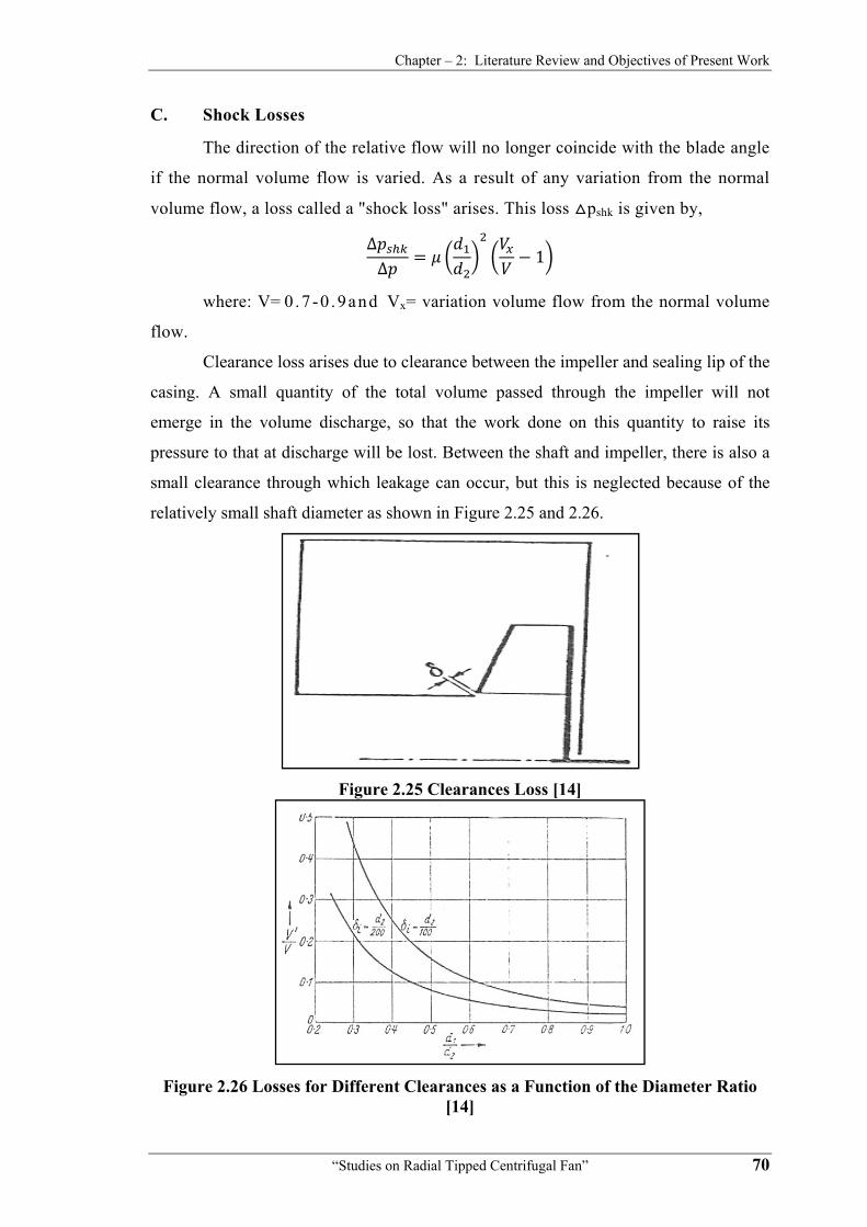
Chapter – 2: Literature Review and Objectives of Present Work
“Studies on Radial Tipped Centrifugal Fan” 70
C. Shock Losses
The direction of the relative flow will no longer coincide with the blade angle
if the normal volume flow is varied. As a result of any variation from the normal
volume flow, a loss called a "shock loss" arises. This loss pshk is given by,
∆∆ 1
where: V=0 .7 -0 .9and Vx= variation volume flow from the normal volume
flow.
Clearance loss arises due to clearance between the impeller and sealing lip of the
casing. A small quantity of the total volume passed through the impeller will not
emerge in the volume discharge, so that the work done on this quantity to raise its
pressure to that at discharge will be lost. Between the shaft and impeller, there is also a
small clearance through which leakage can occur, but this is neglected because of the
relatively small shaft diameter as shown in Figure 2.25 and 2.26.
Figure 2.25 Clearances Loss [14]
Figure 2.26 Losses for Different Clearances as a Function of the Diameter Ratio
[14]

Chapter – 2: Literature Review and Objectives of Present Work
“Studies on Radial Tipped Centrifugal Fan” 71
Diffuser losses are due to conversion of kinetic energy of air discharged by the
impeller into pressure energy in the diffuser or volute. This process is generally
accompanied by huge pressure loss. Because of this, the ratio of the kinetic energy to
the total energy is kept as low as possible.
Bearing loss arises from bearing friction due to bearings used to enclose the
drive shaft. In majority of the cases this loss is exceedingly small. This loss is
proportional to the weight of the rotor and the peripheral velocity of the shaft journal.
The power supplied to the centrifugal fan stage is the power input at the
coupling less the mechanical losses on account of the bearing, seal and disc friction.
The aerodynamic losses occurring in the stage during the flow processes from its entry
to exit are taken into account by the stage efficiency.
For the purpose of fan performance, there are distinct advantages in subdividing
efficiency into appropriate sections according to the type of loss involved. This
subdivision is convenient, for example, if individual losses are examined at a later date
or if only certain losses can be measured.
• Hydraulic Efficiency
All head losses which are taking place between the stage (which means the
impeller inlet and outlet) are considered for the hydraulic efficiency. These include skin
friction losses along with the fluid path from the inlet to the discharge losses due to
sudden change in area or direction of flow and all losses due to eddies.
Considering all the losses in the fan:
η Δ / Δ
• Volumetric Efficiency
Beside the head losses there are capacity losses known as leakage losses. These
take place through the clearance between the rotating and stationary parts of the
machines. The capacity available at the discharge is smaller than that passed through the
impeller by the amount of leakage. The ratio of the two is called the volumetric
efficiency.
η Q
Q QL
• Mechanical Efficiency
Mechanical losses are made up of bearing and transmission losses like gear,

Chapter – 2: Literature Review and Objectives of Present Work
“Studies on Radial Tipped Centrifugal Fan” 72
belt and V- belt losses.
ηm Shaft Power / Input Power
• Total/overall Efficiency
If a particle of air from its entry point into the fan to its discharge from the fan
has been traced, it can be found that the pressure losses are entry loss, friction loss in
the impeller, and shock loss. Therefore, fan efficiency can be expressed as the ratio
of actual work done on the air delivered to the work applied at the shaft coupling is
called fan total efficiency.
ηT = Δp Q / Power Required = ηT = ηhyd ηvol ηm
∆
∆ ∆ ∆ ∆
S. Yedidiah [75] states that according to airfoil theory, the head increases with
the amount of flow rate that the airfoil is displacing in a unit of time. When impeller is
cut down to a smaller diameter, an increase in the loss of head occurs due to the casing.
It results in increase in skin friction and shock losses at higher flow rates. Preliminary
studies show that the distribution of the theoretical heads along the outlet edges can
have a profound effect on the overall efficiency.
A. Satyanarayana Reddy [93] concludes that surface roughness reduces
impeller efficiency and also head and overall efficiency. He suggests that efficiency of
fan/blower can be improved by machining and polishing flow passages.
William C. Osborne [28] observes that the actual performance of a centrifugal
fan at the design point differs from that predicted by Euler’s equation at design point
of operation as follow:
Wst = U2 VU2 - U1 VU1
Graphical presentation of actual performance of fan with respect to ideal is
shown in Figure 2.27. Part of this difference can be accounted for by an adjustment for
inter blade circulation as per Figure 2.28 which results in a reduction of the work done
by the impeller.

Chapter – 2: Literature Review and Objectives of Present Work
“Studies on Radial Tipped Centrifugal Fan” 73
Figure 2.27 Effect Losses in a Backward Curved Centrifugal Fan [28]
Figure 2.28 Inter Blade Circulation [28]
Other factors, which contribute to reduction in output, are as follows:
1) Internal volumetric leakage between the impeller inlet and casing, and also
where the drive shaft enters the casing.
2) Pressure loss within the fan assembly, which comprises three components:
a. Loss due to turning of air through 90° from axial to radial direction.
b. Loss due to flow separation within the blade passages.
c. Loss due to retardation of flow velocity and eddy formation in the
passages of casing.
3) Power loss due to fluid drag on the reverse surface of the impeller back plate.

Chapter – 2: Literature Review and Objectives of Present Work
“Studies on Radial Tipped Centrifugal Fan” 74
The shapes of characteristic curves of centrifugal fan are shown in Figure 2.29.
Figure 2.29 Centrifugal Fan Characteristics [28]
Actual performance of a centrifugal fan differs from that predicted above. This
difference exists due to hydraulic, volumetric and power losses occurring within flow
passage. These losses reduce the work done by the impeller. Losses occur in stationary
as well as moving parts of the fan. The various major losses are:
• Clearance and Leakage Losses
Certain minimum clearances are necessary between the impeller shaft and the
casing, and between the outer periphery of the impeller eye and the casing. Employing
glands minimizes the leakage of the air or gas through the shaft clearance.
On account of the higher peripheral speed and larger shaft diameter, it is very
difficult to provide sealing between the casing and the impeller eye tip. The leakage
through this clearance from the impeller exit gets re-circulated and additional work is
done on a portion of the impeller flow, which does not reach the stage exit. This loss is
governed by the clearance, diameter ratio (d2/d1), and the pressure at the impeller tip.
Static pressure at the impeller exit is high for a higher degree of reaction.
Internal volumetric leakage between the impeller inlet and casing inlet, and also
where the drive shaft enters the casing, is likely to be more serious, and may be given
similar fashion to flow through orifice. Leakage loss is approximated by:
2

Chapter – 2: Literature Review and Objectives of Present Work
“Studies on Radial Tipped Centrifugal Fan” 75
Where coefficient of discharge Cd is 0.6 to 0.7.
• Hydraulic or Pressure Losses
Major portion of hydraulic or pressure losses is due to fluid friction in stationary
surfaces and rotating blade passages. The pressure losses that take place along the
various flow passages such as inlet duct, impeller entrance, impeller, volute and outlet
duct are collectively considered as hydraulic losses. Losses due to fluid friction depend
on the friction factor, passage length and square of the fluid velocity. Therefore, a stage
with relatively longer impeller, diffuser and volute passages and higher fluid velocities
shows poor performance.
There is little information available on pressure losses within fan assembly. It is
felt to be reasonable to consider three phases of losses.
• Impeller Entry Losses
Air enters the impeller eye through a reducing section from the casing inlet duct.
Fluid turns through a right angle prior to entering the impeller inlet blade passages. The
loss here may be written:
∆p12
Where ki is a loss factor probably of the order of 0.5 to 0.8 and Vo is the air
velocity at impeller eye.
• Impeller Passage Losses
Pressure loss will occur within the blade passage due to flow separation since
the relative velocity of the air decreases due to passage friction. This loss may be
written as:
∆12 W
(At design point of maximum efficiency kii is in order of 0.2 – 0.3 for sheet
metal blades and rather less for aerofoil section).
• Diffuser or Volute Losses
The diffuser or volute casing is designed with the intention of permitting free
vortex flow conditions. Such kind of perfect flow is not available in practice. There is
almost 2.5 times [28] increase of area from impeller exit blade passage to the volute
casing inlet. There is thus a tendency of retardation of flow velocity, with resultant eddy
formation. However, it is not east to compare flow under these conditions with that at a
sudden enlargement in normal pipe flow. Losses in the diffuser also occur due to

Chapter – 2: Literature Review and Objectives of Present Work
“Studies on Radial Tipped Centrifugal Fan” 76
friction and flow separation. It seems reasonable to express this pressure loss as
following:
∆12 V
V4 is average velocity at fan outlet. At maximum efficiency, kiii is of the order of
0.4 and will vary with deviation from design conditions.
• Mechanical or Power Losses
There may be power loss due to fluid drag on the reverse surface of the impeller
back plate. Disc friction loss due to fluid friction around the rotating impeller and losses
in bearings and transmission devices are considered as mechanical or power loss.
The power required to start rotating a disc in a fluid is known as the disc
friction. This power is transformed into heat and may appreciably increase the
temperature of the fluid.
The disc friction loss is due to two actions occurring simultaneously. It includes
actual friction of the fluid on the disc and a pumping action. The fluid, which is in
contact with the disc or near to it, is thrown outward by the centrifugal action and
circulates back towards the shaft which is to be pumped again and again as shown in
Figure 2.30. This may be significant for large fans. The loss may be estimated as:
T ρ ω
5
(Where f is material friction factor in order of 0.005)
Bearing loss or transmission loss occurs when bearings or transmission devices
are incorporated to support the drive shaft and to transmit the power from motor to the
drive shaft of the blower/fan.
Figure 2.30 Circulation Caused by Impeller Disc Friction [26]
Chapter – 2: Literature Review and Objectives of Present Work
“Studies on Radial Tipped Centrifugal Fan” 77
V. Sivakumar [21] found that flow coefficients for radial fan and blowers
ranges from 0.25 to 0.3. His conclusions are:
• Increase in vane angle at outlet increases volume flow.
• There is a marked increase in efficiency by the use of vane less diffuser
and also efficient operating range is extended.
• Flow leaving the impeller is not uniform. Flow near back shroud is more
disturbed than the front shroud. This indicates the presence of thick
boundary layer in this region.
• Flow inside the vane less diffuser is smoother than that in the volute
casing (without vane less diffuser) for the same flow coefficient.
• Return flow and hence the separation regions are encountered near the
back shroud at the exit of the diffuser.
• Radial vanes give better efficiency compared to forward curve vanes.
J. H. Bunjes, J. G. H. Opde woerd [94] concludes that:
• Hydraulic friction losses are proportional to impeller relative velocity
head and depend upon the geometry of the passages and the friction
coefficient determined by surface roughness and Reynolds number.
• Blade loading losses results from blade lift, incidence and velocity
distribution.
• Mechanical losses include disc friction loss resulting from the velocity
distribution profile in the space between the impeller shrouds and pump
casing and seal friction and bearing losses.
• Volumetric losses are due to internal leakage in the pumps through the
wear ring clearances and balance drum in the case of multi stage pumps.
• Impeller tip clearance losses are determined by the clearance between the
impeller blade tips and the pump housing.
Kamaleshaiah, Venkatrayulu and Ramamurthy [95] presented an improved
method for predicting the performance of a centrifugal compressor stage. The prediction
method is based on one-dimensional approach with empiricisms for the loss models and
boundary layer growth within the blade channel.
For a given overall geometry of the compressor and inlet flow conditions, the
method evaluates quite rapidly the compressor performance characteristics with a
reasonably acceptable error. The method is validated with a few typical compressor

Chapter – 2: Literature Review and Objectives of Present Work
“Studies on Radial Tipped Centrifugal Fan” 78
configurations and their experimental performance maps available in literature. The
predicted characteristics are in close agreement with the experimental results.
R. K. Srivastava [96] concludes that:
• Low specific speed centrifugal pumps are not giving good performance
due to more disc friction and hydraulic losses.
• As specific speed decreases, hydraulic and disc friction losses increases.
• Losses due to over lapping of boundary layers are applicable in low
specific speed pumps.
Farge, Johnson and Maksoud [97] said that reduced static pressure
distribution is little affected by tip leakage. However, the small decrease in the blade-to-
blade pressure gradient close to the shroud can be activated to tip leakage. The effects of
tip leakage have been studied using a 1-m-dia shrouded impeller where a leakage gap is
left between the inside of the shroud and the impeller blades. A comparison is made
with results for the same impeller where the leakage gap is closed. The static pressure
distribution is found to be almost unaltered by the tip leakage, but significant changes in
the secondary velocities alter the size and position of the passage wake. Low-
momentum fluid from the suction-side boundary layer of the measurement passage and
tip leakage fluid from the neighboring passage contributes to the formation of a wake in
the suction-side shroud corner region. The inertia of the tip leakage flow then moves
this wake to a position close to the center of the shroud at the impeller outlet.
Y. Senoo and H. Hayami [98] have discussed about effects of losses on input
power and efficiency as following:
• The input power to the blower/fan is increased due to the additional
moment arising out of disc friction and mechanical friction at the
bearings and seals. These effects may be handled as mechanical
efficiency.
• The effective output power is considerably reduced by pressure losses in
the impeller, in the diffuser and in the casing. Pressure loss in an
impeller is the sum of various kinds of losses such as friction loss,
deceleration loss: secondary flow loss and incidence loss. These losses
are estimated based on experimental data for respective types of
impellers. Further, about 30% or more of the kinetic energy at the exit of

Chapter – 2: Literature Review and Objectives of Present Work
“Studies on Radial Tipped Centrifugal Fan” 79
the impeller is not converted into pressure in the diffuser. Such pressure
losses may be handled as hydraulic efficiency.
• If a part of fluid at the impeller exit is leaked outside or returned to the
suction port after it loses the angular momentum, the input power to the
blower/fan is increased in proportion. The effect may be handled as
volumetric efficiency.
Johnson and Farge [99] have presented lecture notes. These lecture notes
provide an overview of the different inlet and outlet volutes for radial impellers. It
describes the advantages and disadvantages of the different geometries, the relation
between flow and geometry, the impact on the downstream or upstream impeller, the
loss mechanisms and some loss prediction models. The main purpose is to provide an
insight into the flow structure that can be used later to improve the performance. The
use of CFD is not discussed but the flow models presented here may help to get a better
understanding of the CFD output. Base on their study, they stated that the impeller
efficiency is reduced by about 8.5% by the hub inlet distortion for this impeller. This is
largely due to separation of the pressure side boundary layer at the leading age that may
be avoided in other impellers.
Gandhi and Subir Kar [100] studied that impeller friction loss can lower the
predicted head and the recirculation can shift the predicted curve to smaller values of
the net pump flow rate. Analysis shows the influence of volute in predicting the pump
performance and yields a modification to the impeller head due to mechanical energy
losses in the volute. The volute flow is equally dependent on the geometry as on the
impeller exit flow conditions. The later one depends on the volute circumferential
pressure distortion. This means that any prediction method should account for this
strong interaction. Swirl is the main source of losses in a volute. Optimum volute
performance requires minimum radial velocity at impeller exit. Simultaneous
optimization of the impeller and the volute is recommended.
J. D. Denton [34] defines loss as ‘any flow feature that reduces efficiency of a
turbo machine’. Further, he categorizes losses as
1. Profile Loss
2. Secondary Loss (End Wall Loss)
3. Tip Leakage Loss

Chapter – 2: Literature Review and Objectives of Present Work
“Studies on Radial Tipped Centrifugal Fan” 80
Profile loss is generated in the blade boundary layers well away from end walls.
The extra loss arising at a trailing edge is usually included as profile loss. End wall loss
or secondary loss arises partly from the secondary flows generated when the annulus
boundary layers pass through a blade row. Secondary loss is sometimes taken to include
all the losses that cannot be otherwise accounted for.
Tip leakage loss arises from the leakage of flow over the tips of rotor blades.
The detailed loss mechanisms clearly depend on whether the blades are shrouded or un-
shrouded.
He suggests the following loss coefficients for better understanding of flow in
turbo machines.
• Stagnation pressure loss coefficient ⁄
• Energy or Enthalpy loss coefficient ⁄
• Entropy loss coefficient ·∆
Where p01, p02 are stagnation pressure at inlet to blade row or stage and
exit from blade row or stage, respectively.
p1 is static pressure at inlet to blade row or stage.
h2, h2s are static and isentropic enthalpies at exit from blade row or stage,
respectively.
h01, h1 are stagnation and static enthalpies at inlet to blade row or stage,
respectively.
T2 is static temperature at exit from blade row or stage.
ΔS is change in specific entropy.
He discusses about 2-D losses in Turbo machinery wherein the following losses
are included:
• Blade boundary layer loss
This loss is estimated by a Loss coefficient
0.5 ⁄
2 ∆⁄ 6∆ ⁄ tan tan
Assuming a rectangular velocity distribution and Cd is constant,
S=total entropy, α2, α1 are flow angles measured from axial direction,
⎯V is mean flow velocity and ΔV is change in flow velocity
• Trailing edge loss
It is about 32% of the boundary layer loss or 21% of total loss

Chapter – 2: Literature Review and Objectives of Present Work
“Studies on Radial Tipped Centrifugal Fan” 81
• Tip leakage loss
This loss is estimated by the formula
∆ 0.5⁄ 2 ⁄ 1 tan tan⁄
⁄
Where h is blade span, mL is leakage mass flow, mm is main stream
mass flow, Cc is jet contraction coefficient
• He gives the following Loss coefficient for vane less space immediately
after impeller 4 · ∆ cos⁄
Where h= passage height, Δr= radius change, α= swirl angle, Cd=0.5
He briefs the other sources of loss as Loss due to unsteady flow, shock loss and
loss due to windage and cooling flows. Any periodic motion of the shock will increase
loss due to increased entropy generation. Windage loss and disk cooling flows is the
loss due to viscous friction on all parts of the machine other than blade and annulus
boundaries, where it has already been accounted for .It is considered in terms of the
viscous torque on rotating disks and hence called disc friction loss.
Wakes, vortices and separations from one blade row often mix out in the
downstream blade row. When vortex is stretched or compressed longitudinally its
kinetic energy varies as square of its length. When this is dissipated by viscous effects,
it will increase loss.
Unsteady flow can affect generation through dissipation of span wise vortices
shed from a trailing edge as a result of changes in blade circulation.
In his concluding remarks, Dr. J. D. Denton emphasizes that the understanding
of losses will be improved by thinking loss in terms of entropy generation. Tip leakage
loss, subsonic trailing edge loss and losses due to blade surface separation are estimated
using empirical data. End wall loss, transonic trailing edge loss and loss due to mixing
in a downstream blade row can be estimated approximately using empirical
correlations.
V. M. Sharathkumar [101] concluded that circumferential distortion effects
changes total pressure, static pressure, flow angles and conditions of shock less entry.
B. Laksminarayana and A. Basson [102] explains that the leakage mass flow
is one of the important parameters in assessing the aerodynamic loss and its
performance. The leakage mass flow is given by

Chapter – 2: Literature Review and Objectives of Present Work
“Studies on Radial Tipped Centrifugal Fan” 82
Where VL= leakage velocity normal to the blade surface
s = the distance along the blade surface
ρ= density of fluid
τ= tip clearance height
dz= span wise distance (measured from end wall)
They noticed that major leakage flow and losses occur beyond mid chord due to
increased loading and decreased blade thickness in this region.
R. H. Aungier [103] suggests the following formulae to estimate Impeller
windage and disk Friction (IDF) and cover seal leakage work input (IL) for covered
impellers:
IDF IL CMD CMC ρ2U2 2 /2m mLIB/m
Where, CMD = Disc torque coefficient for disc parameter
CMC = Disc torque coefficient for cover parameter
ρ2 = gas density at impeller tip
U2 = blade speed at impeller tip=ωr=tangential velocity
m = mass flow
mL= mass flow for leakage
IB = work input coefficient for blade parameter
Further, for calculating Impeller internal losses, he gives the following formulae:
• Adiabatic head loss coefficient
∆ 2 / /13
Where, Cm1= absolute meridional velocity at impeller blade leading edge
Cf = skin friction coefficient
m1, m0=meridional co-ordinates at impeller blade leading edge and at
impeller eye
b1= hub-to-shroud passage width at impeller blade leading edge
αc1, αc2= stream line slope angles with axis
• Incidence loss
∆ 0.4 / sin ⁄
Where W1= relative velocity at impeller leading edge
β1= blade angle with respect to tangent at impeller leading edge

Chapter – 2: Literature Review and Objectives of Present Work
“Studies on Radial Tipped Centrifugal Fan” 83
Cm1= absolute meridional velocity at impeller blade leading edge
U2 = blade speed at impeller tip=ωr=tangential velocity
• Entrance diffusion loss
∆ 0.4 2⁄ ∆
ΔqDiff > 0,
Wth = relative velocity at throat
• Impeller friction loss
∆ 2 ⁄ ⁄
2⁄
2⁄
• Blade loading and hub-to-shroud loading losses
∆ ∆ ⁄ 48⁄ (Blade loading loss)
∆ ⁄ 12⁄ (Hub-to-shroud loss)
⁄
2⁄
2⁄
∆ 2 ⁄
Where LSB = splitter blade mean streamline meridional length
d2=diameter at impeller tip: LB = length of blade mean camber line
IB= work input coefficient for blade
Z= effective number of blades = /
ZFB= Number of splitter blades, L= blade streamline meridional
length=m2-m1
• Discharge profile distortion loss
∆ 0.5 1 2
Where λ = tip distortion factor=1/ (1- β2)
∆ ⁄ 0.3 ⁄ / 2⁄
∆ 2 ⁄ ⁄
22⁄ 12⁄
• Wake mixing loss
∆ 0.5 /
: for Deq<2

Chapter – 2: Literature Review and Objectives of Present Work
“Studies on Radial Tipped Centrifugal Fan” 84
/2: For Deq >2
⁄
Where A2 =discharge area inside the blades
K. L. Kumar [10] lists following factors, which account for the departure of the
actual flow from the ideal flow:
• Existence of viscosity: viscous resistance, boundary layer formations,
and separation of flow.
• Finite number of blades: flow through bladed channels, secondary flows
in the bladed passages and leakage effects.
• Existence of compressibility, density variations, temperature rise and
shock phenomena.
• Off design operating conditions, velocities and angles different from the
design values.
• Head loss due to frictional effect are expressed as,
Where hf =head lost due to friction and shearing, Q= Volumetric flow
rate,
k= constant.
• Losses due to improper fluid incidences on the blades at the inlet and
lack of complete guidance by the blades are called turning losses.
Turning losses are expressed as
Where ht = head lost in turning due to improper incidence or flow
guidance,
Q= Volumetric flow rate, Qn= designed flow rate, C = a constant
The effect of all losses on the Head- Discharge characteristic of a typical
centrifugal impeller turbo machine is shown in Figure 2.31. The actual characteristic is
lower than the Euler’s characteristic at all values of the discharge. The difference
between them is the largest at very high and very low discharge.

Chapter – 2: Literature Review and Objectives of Present Work
“Studies on Radial Tipped Centrifugal Fan” 85
Figure 2.31 Actual and Euler’s H-Q Characteristic Curve [10]
R. J. Kind [60] studied flow behavior and performance of squirrel-cage type
centrifugal fans. Experimental and analytical study has lead to following conclusions:
• The volute can have a strong influence on the overall performance
characteristics of the machine.
• The inlet losses and volute friction losses are relatively unimportant.
Blading losses are, however, very important and are responsible for
approximately half of the overall losses.
• To improve efficiency, one should focus on gap flow and blading losses.
G. L. Morrison, M. T. Schobeiri and K. R. Pappu [104] introduced Five-hole
pressure probe analysis technique. Five-hole pressure probes are becoming more useful
with the development of small inexpensive fast response pressure transducers, computer
controlled traversing systems, and computer based data acquisition and analysis. A
schematic of the end of a five-hole pressure probe is presented in Figure 2.32.

Chapter – 2: Literature Review and Objectives of Present Work
“Studies on Radial Tipped Centrifugal Fan” 86
Figure 2.32 Schematic of a Generic Five-Hole Pressure Probe
The probe can be operated in two ways. The most simple in terms of data
analysis is the nulling arrangement where the probe is mounted on a five degree of
freedom traversing system and is oriented such that the X-axis is parallel to the flow
( are both zero). The center pressure tap, P5, then measures the stagnation
pressure and the pressures in the four outer tubes are equal (P1 = P2 = P3 = P4) and
proportional to the static pressure. This nulling technique requires a very sophisticated
traversing system and long data acquisition time since the probe must be pitched and
yawed at each measurement location until the four pressures are equal. This can take a
long time, especially if the probe is small and has a slow time response. This paper
addresses the non-nulling technique in which the pressure probe undergoes an extensive
calibration which is then used to determine the magnitude and direction of the flow with
respect to the coordinates of the probe. The non-nulling technique is performed by
setting the probe at constant pitch and yaw values with respect to the test section,
traversing the probe over the flow field, and measuring the five pressures at each
measurement location. From these five measured pressures, the direction and magnitude
of the flow with respect to the X-axis of the pressure probe are determined There is a
maximum angle the flow can make with respect to the axis of the probe beyond which
the flow separates from the probe. When this occurs the data cannot be reduced to
obtain the velocity since the pressure taps in the separated regions do not vary
significantly or monotonically with flow angle. Most data analysis techniques for the
non-nulling operation of the probe require that the probes are manufactured to exacting
tolerances such that the response in each of the four pressure taps around the perimeter
of the probe (P1, P2, P3 and P4) is completely symmetrical. The objective of this work is

Chapter – 2: Literature Review and Objectives of Present Work
“Studies on Radial Tipped Centrifugal Fan” 87
to present a data reduction technique which will compensate for nonsymmetrical probes
and which will establish the range of flow angles a specific probe can be used.
A refinement on the method used to analyze five-hole pressure probe data
obtained using the non-nulling technique has been presented. The use of advanced three
dimensional curve-fit analysis programs has made it possible to obtain relatively simple
analytical expressions for the four calibration functions,
, ), , ), , , , which are required to convert
the pressures measured by a five-hole pressure probe into the magnitude and direction
of the flow with respect to the axis of the probe. These equations are usually simple
algebraic relationships which may have as many as ten coefficients. Though lengthy to
enter into a data reduction program, they are quickly computed and produce excellent
results. The three dimensional graphical presentation of the calibration
curves, , ), , ), , , , obtained directly from
calibration data are invaluable in evaluating the performance of an individual probe and
determining the range of pitch and yaw angles the probe is capable of measuring.
H. W. Oh, K. Y. Kim [105] classifies losses into internal losses and External
losses.
Internal losses
• Entrance loss
∆ /2
Where fent=0.13
V0= Absolute velocity ahead of impeller
• Incidence loss
∆ /2
Where finc=0.5-0.7
Wui= tangential component of the impeller inlet relative velocity
• Diffusion loss
∆ 0.05 /
Where
1 ⁄ . ⁄
⁄ ⁄2 ⁄
W2=relative velocity at impeller exit
U2= tangential impeller speed at exit
Chapter – 2: Literature Review and Objectives of Present Work
“Studies on Radial Tipped Centrifugal Fan” 88
W1t= relative velocity at impeller tip inlet
HEuler= Euler head
Zr= number of impeller blades
D1t=diameter of impeller tip at inlet
D2= diameter at impeller exit
• Skin friction loss
∆ 2 ⁄
Where 2 3 8⁄
Cf= skin friction coefficient
Lb= impeller flow length
Dhyd= hydraulic diameter
V1t, V2= absolute velocities at impeller inlet tip and impeller exit,
respectively.
W1, W1h= relative velocities at impeller tip inlet and impeller hub
inlet, respectively.
• Clearance loss
∆ 0.6 ⁄ ⁄ 4 2⁄⁄ /
Where ε = clearance between impeller tip and casing
b2=impeller width at outlet
Vu2=absolute velocity at tangential direction at impeller exit
r1t, r2t = radii at impeller tip inlet and impeller exit, respectively
r1h= radius at impeller inlet hub
Vm1m =Absolute velocity at meridional directions or root-mean-
square position at impeller inlet
• Mixing loss
∆ 1/ 1 1 1⁄ 2⁄
Where α2= absolute flow angle from the meridional direction at
impeller exit
εwake = wake friction of the blade –to-blade space
b* = ratio of vane less diffuser inlet width to the impeller exit width
• Separation loss
∆ 0.61 ⁄ 1.4 2 ⁄

Chapter – 2: Literature Review and Objectives of Present Work
“Studies on Radial Tipped Centrifugal Fan” 89
External losses
• Recirculation loss
∆ 4.32 10 sin 3.5 2 /2
• Leakage loss
∆ /2
Where Qcl = volume flow at clearance in m3/s
0.816 2∆ ⁄
∆ /
2⁄
2⁄
Lθ= impeller meridional length
Q* = volume flow including leakage, m3/s
B. P. M. Van Esch, N. P. Kruyt [106] derives various formulae for power and
turbo machine losses as following:
• The shaft power can be written as
∆
Pfluid= Power imparted by the impeller to the fluid = ρg (Q+Qleak)Hinv
Where Hinv= inviscid head
Q = flow rate
Qleak= leakage flow
ΔPdf= power loss due to shear stress at the impeller external surfaces
(disc friction)
• He derives hydraulic power loss in the impeller as
∆ ∆
Where Δ
Hi is head measured between stations located just above and downstream
of impeller
• Further, he gives the following formula for calculating leakage loss:
Leakage loss, ∆
Final value of head= Hi - ΔHhydr,v
• ΔHhydv is the loss of head in volute

Chapter – 2: Literature Review and Objectives of Present Work
“Studies on Radial Tipped Centrifugal Fan” 90
∆ ∆ ∆
Where Pnet is net power relates to the pump’s head H & is equal to ρgQH
∆ ∆
On the basis of above calculations the overall power loss is derived as follows:
Overall power loss=∆ ∆ ∆ ∆ ∆ ∆
Where ΔPhydi is Hydraulic power loss in impeller
ΔPhydv is Hydraulic power loss in volute
ΔPleak is Leakage loss
ΔPdf is disk friction loss
ΔPmech is power loss due to friction in bearings and seals
S. M. Yahya [9] enumerates the losses for a centrifugal fan as Impeller entry
losses, Leakage loss, Impeller losses, Diffuser and volute losses and Disc friction loss.
By accounting for the above losses, the actual performance of the fan can be predicted
from that obtained theoretically. The basic mechanism of the losses for a centrifugal fan
is similar to centrifugal compressor stages as shown in Figure 2.33 and 2.34.
Figure 2.33 Variations of Shock Losses with Incidence [9]

Chapter – 2: Literature Review and Objectives of Present Work
“Studies on Radial Tipped Centrifugal Fan” 91
Figure 2.34 Losses and Performance Characteristics of a CF Turbo Machine Stage
[9]
2.5 Computational Fluid Dynamics (CFD) Numeric Analysis
Turbo-machines comprise various types of fans, compressors, pumps and
turbines. In the earlier phase of design and development of turbomachines since
perception, many researchers have done their research work by performing laboratory
experiments or by making analysis of actual performance data available. This was a
slow process of development.
In present era of computerization and its development and advancement, virtual
three-dimensional flow analysis is feasible and allowing designer to have better
estimate of influence of spatial parameters on performance of the machine. CFD
provides an accurate alternative to scale model testing, with variations available in
simulation parameters. Advanced solvers contain algorithms which enable robust
solutions of the flow field in a reasonable time. As a result of these factors,
Computational Fluid Dynamics is now an established industrial design tool, helping to
reduce design time scales and improve processes throughout the engineering world.
Various flow phenomenons occurring inside turbomachine can be numerically
analyzed with the help of commercially available CFD software. The set of equations
which describe the processes of momentum, heat and mass transfer are known as the
Navier-Stokes equations. These partial differential equations were derived in the early
nineteenth century and had no analytical solution but it can only be discretized and
solved numerically.
Centrifugal fan design performance can be truly ascertained by experimental
evaluations, but CFD analysis can greatly help in reducing number of experimental

Chapter – 2: Literature Review and Objectives of Present Work
“Studies on Radial Tipped Centrifugal Fan” 92
iterations. CFD can also help to understand profile distribution of mass flow, pressure
and velocity at infinitesimal planes of centrifugal fan geometry under study. This could
not be possible merely by experiments and hence CFD analysis and experimental
evaluation are equally important and mutually exclusive.
Here literature review is focused on use of CFD techniques to make virtual
performance analysis of turbo-machines.
P. J. Roache [35] made quantification of uncertainty in computational fluid
dynamics. This review covers verification, validation and confirmation for
computational fluid dynamics (CFD). It includes error taxonomies, error estimation,
convergence rates, surrogate estimators, nonlinear dynamics, and error estimation for
grid adaptation.
Hsin-Hua Tsuei, Kerry Oliphant and David Japikse [36] have developed
method for rapid CFD modeling for turbo machinery. This study draws on a set of
seven different stages, for which much measured data is available, and provides answers
to issues of sufficient depth to sensibly guide engineers in the economical and accurate
utilization of their CFD tools. A base for rapid calculations is established: it is expected
that the design future will focus intensely on agile, easy-to-use CFD as a base for
advanced design development.
Hsin-Hua Tsuei and J. Blair Perot [107] developed advanced turbulence
model for transitional and rotational flows in turbo machinery. It contains turbulence
model which is expected to capture the full details of 3D non-isotropic turbulence for
wide variety of flows. The greater accuracy is expected to be achieved with a
computational cost similar to an enhanced k-ε model while providing detailed Reynolds
stress information for the mean flow.
Hsin-Hua Tsuei [108] explained the role of CFD in turbo machinery designs
process by using a series of typical turbo machinery test cases for centrifugal and axial
turbo machines.
Hsin-Hua Tsuei, Biing-Horng Liou and S. T. John Yu [109] developed direct
calculation method for turbo machinery flows using space-time conservation element
and solution element method. A three-dimensional space-time Conservation Element
and Solution Element (CE/SE) code in cylindrical coordinates has been developed. For
the study, the blade-to-blade flow field was first investigated to address the fundamental
issues associated with rotation, and blade-to-blade loading. The algebraic Baldwin-

Chapter – 2: Literature Review and Objectives of Present Work
“Studies on Radial Tipped Centrifugal Fan” 93
Lomax turbulence model was also implemented to address the shock wave-boundary
layer interaction phenomenon.
Akhras, J. Y. Champagne and R Morel [110] studied rotor–stator interaction
in a centrifugal pump equipped with a vaned diffuser. Their work provides the results of
a detailed flow investigation within a centrifugal pump equipped with a vaned diffuser.
Results are presented as animations reconstituting a temporal evolution of the flow
permitting a better comprehension of the complex flow structure existing between the
two interacting blade rows. At the design flow rate, the presence of the vanes seems to
have a limited effect on the impeller flow structure, except when the suction side of the
blades is facing the diffuser vanes.
Mark R. Anderson, Fahua Gu and Paul D. MacLeod [111] have worked on
application and validation of CFD in a turbo machinery design system. Detailed
comparison to test data of 10 different stages is made.
Kwang-Yong Kim, Seoung-Jin Seo [112] has used response surface method
using a three-dimensional Navier-Stokes analysis to optimize the shape of a forward-
curved-blade centrifugal fan. For the numerical analysis, Reynolds-averaged Navier-
Stokes equations with the standard k-ε turbulence model are discretized with finite
volume approximations. The SIMPLE algorithm is used as a velocity–pressure
correction procedure. In order to reduce the huge computing time due to a large number
of blades in forward-curved-blade centrifugal fan, the flow inside of the fan is regarded
as steady flow by introducing the impeller force models. The geometry of fan used is
shown below in Figure 2.35.
Figure 2.35 Geometry of a Forward-Curved-Blade Centrifugal Fan
[112]

Fou
scroll, and
points for r
method is
optimizatio
T.
interaction
interaction
flow simula
two-dimens
(PIV) and
Tascflow c
calculation
using the s
experiment
Fi
J. H
practice usi
Jiab
of internal f
A th
blade centr
ur design va
width of im
response eva
used for th
on, the effici
Meakhail,
in a Cen
region betw
ation of the
sional insta
numerical
commercial
and a roto
teady result
tal and CFD
igure 2.36 C
H. Horlock
ing computa
bing Wang
flow pheno
hree-dimens
rifugal fan h
“Studies
ariables are
mpeller are
aluations ar
he optimizat
iency is suc
S. Park
ntrifugal Fa
ween the im
e whole mac
ntaneous ve
simulation
code. A f
or-stator sim
ts as an ini
D results for
Compariso
k and J. D
ational fluid
g, Yingda O
mena in a m
sional, stead
has been an
Chapter – 2
on Radial Tip
location cu
selected to
re selected b
tion on the
ccessfully im
[113] has
an. They r
mpeller and
chine of a s
elocity mea
n of impell
frozen rotor
mulation m
tial guess. A
the perform
on Between[11
D. Denton
d dynamics
Ou and Keq
multi-blade
dy, incompr
nalyzed num
: Literature R
pped Centrifug
ut-off, radiu
optimize sh
by optimal d
response s
mproved.
made stu
report velo
vaned diffu
ingle stage
asurement u
ler-diffuser-
r simulation
model is use
A good agr
mance as sh
n Experime3]
[114] mad
in a current
qi Wu [115
CF fan.
ressible, tur
merically. R
Review and Ob
gal Fan”
us of cut-off
hapes of sc
design and a
surface. As
udy on imp
city measu
user and the
centrifugal
using particl
-volute inte
n model is
ed for the
reement is o
hown in Figu
ental and C
e review o
t perspectiv
5] have mad
rbulent flow
eynolds-ave
bjectives of P
ff, expansion
croll and bla
a linear pro
a main res
mpeller-diffu
urement da
e results of
fan. They h
le image Ve
eraction us
used for t
unsteady c
obtained be
ure 2.36.
CFD Results
of some ear
ve.
de numerica
w field insid
eraged Nav
resent Work
94
n angle of
ades. Data
gramming
sult of the
user-volute
ata in the
numerical
have done
elocimetry
ing CFX-
the steady
calculation
etween the
s
rly design
al analysis
de a multi-
vier-Stokes

equations w
volume me
The
the flow, e
revealed bo
flow revers
near the im
rotor exit an
G.
This resea
complex, in
flows. The
performanc
it is conclu
simultaneou
impeller an
with the sta
ethod.
e calculation
especially
oundary lay
sal from the
mpeller inlet
nd the press
Figure 2.
. Pavesi [1
rch paper
nvolving cu
design of
ce can be in
uded that a
us solution
nd volute. St
Figure 2.3
“Studies
andard k-ε
n results hav
in the blad
yer separati
e high press
t, flow recir
sure fluctua
.37 Compu
16] has ma
mentions t
urvature, sy
the centrif
ncreased onl
correct sim
n of the thr
treamline pa
38 Streamli
Chapter – 2
on Radial Tip
turbulence
ve shown co
de passages
ion at the l
sure region
rculation ne
ation on the
utational Gr
ade study on
that the fl
ystem rotat
fugal pump
ly through d
mulation of
ree-dimensi
atterns at va
ine Pattern
: Literature R
pped Centrifug
model hav
omplex thre
s near the
leading edg
inside the v
ar the shrou
blade surfa
rid of the B
n impeller,
low in cen
ion, separa
s has alrea
detail study
the impelle
ional unstea
arying flow
ns at Varyin
Review and Ob
gal Fan”
ve been disc
ee-dimensio
shroud sid
ge on the b
volute to the
ud side, a je
ace as shown
Blade Regio
volute and
ntrifugal pu
tion, turbul
ady reached
y of the inte
er/volute int
ady Navier
w rates are sh
ng Flow Ra
bjectives of P
cretized by
onal charact
de. The res
blade suctio
e low pressu
et-wake pat
n in Figure
on [115]
d diffuser in
umps is ex
lence, and
d a level th
ernal flow. T
teraction re
r-Stokes equ
hown in Fig
ates [116]
resent Work
95
the finite
teristics of
sults have
on surface,
ure region
tern at the
2.37.
nteraction.
xceedingly
secondary
hat overall
Therefore,
equires the
uations in
gure 2.38.

Chapter – 2: Literature Review and Objectives of Present Work
“Studies on Radial Tipped Centrifugal Fan” 96
Hong Yang, Dirk Nuernberger, Hans-Peter Kersken [117] developed a
three-dimensional hybrid structured-unstructured Reynolds-averaged Navier-Stokes
(RANS) solver to simulate flows in complex turbo machinery geometries. It is built by
coupling an existing structured computational fluid dynamics (CFD) solver with a
newly developed unstructured-grid module via a conservative hybrid-grid interfacing
algorithm, so that it can get benefits from the both structured and unstructured grids.
The unstructured-grid module has been developed with consistent numerical algorithms,
data structure, user interface and parallelization to those of the structured one. The
numerical features of the hybrid RANS solver are its second-order accurate
upwind scheme in space, its SGS implicit formulation of time integration, and its
accurate modeling of steady/unsteady boundary conditions for multistage turbo
machinery flows. The hybrid-grid interfacing algorithm is essentially an extension of
the conservative zonal approach that has been previously applied on the mismatched
zonal interface of the structured grids, and it is fully conservative and also second-order
accurate. Mismatched grids at blocked interface allow users to have great flexibility to
build the hybrid grids even with different structured and unstructured grid generators.
The performance of the hybrid RANS solver is assessed with a variety of validation and
application examples. It is able to cope up with the flows in complex turbo machinery
geometries and to be promising for the future industrial applications.
ANSYS Inc. [118] has given tutorials on multiple rotating reference frames.
This tutorial illustrates the procedure for setting up and solving a problem using the
MRF capability. Some FLUENT features such as specifying different frames of
reference for different fluid zones, setting the relative velocity of each wall and
calculating a solution using the segregated solver are demonstrated in these tutorials.
A. Behzadmehr, Y. Mercadier and N. Galanis [119] have made sensitivity
analysis of entrance design parameters of a backward inclined centrifugal fan using
DOE method and CFD calculations.
A design of experiments (DOE) has been performed to study the effect of the
entrance conditions of a backward-inclined centrifugal fan on its efficiency. The
parameters involved are the base radius of the motor hub, the radius of the fan entry
section, the deceleration factor throughout the entry zone (from the entry of the fan to
the entry of the blade), and the solidity factor. Numerical simulation coupled with the
DOE has been used for the sensitivity analysis of the entrance parameters. The effects
of these parameters and their interactions on the fan efficiency are presented. A linear

Chapter – 2: Literature Review and Objectives of Present Work
“Studies on Radial Tipped Centrifugal Fan” 97
regression with three parameters has been performed to establish the efficiency
distribution map. The methodology employed is validated by comparing the predicted
results from the DOE and those from the numerical simulation of the corresponding fan.
Fahua Gu and Mark R. Anderson [120] have developed CFD based through
flow solver in a turbo machinery design system. In this paper an Euler through flow
approach is described and the steps required for constructing stream surface,
modifications for the incidence and deviation and throat area correction are presented.
This solver creates and modifies the machine geometries and predicts the machine
performance at different levels of approximation, including one-dimensional design and
analysis, quasi-three-dimensional methods (blade-to-blade and through flow) and full-
three-dimensional steady-state CFD analysis. The flow injection and extraction
functions are described, as is the implementation of the radial mass distribution. Some
discussion is dedicated to the shock calculation and examples are provided to
demonstrate the pros and cons of the Euler through flow approach and also to
demonstrate the potential to solve for a wider range of flow conditions, particularly
choked and transonic flows which limit stream function based solvers.
Moulay Bel Hassan, Asad Sardar and Reza Ghias [121] have made CFD
simulations of an automotive HVAC blower. It is operating under stable and unstable
flow conditions.
In this study, CFD simulations for different blowers are performed. The
realizable k-ε turbulence model was used on the Reynolds Averaged Navier-Stokes
approach to model complex flow field properly.
Steady state analysis showed good correlation for the stable flow conditions
(high airflow and low pressure), whereas this approach showed large discrepancies for
unsteady flow conditions (low airflow and high pressure). By a transient simulation and
realizable k-ε turbulence model, the CFD results showed good results compared to
experimental test results. The graph shown in Figure 2.39 gives results obtained from
numerical simulation at varying airflow.

K.
Analysis o
Boundary L
Her
made to ch
separation
suction slo
converging
Figure 2.4
Figure
Vasudeva
of a Centr
Layer Suctio
re by use o
eck the effe
points. Thi
ots correspo
g configurati
40 Geometr
“Studies
2.39 Pressu
Karanth
rifugal Fan
on Slots.
of CFD as a
ect of bound
s research w
onding to
ions for the
ric Configuo
Chapter – 2
on Radial Tip
ure vs. Airf
and N. Y
n for Perfo
an analytica
dary layer s
work attem
various ge
slots as sho
urations foron the Imp
: Literature R
pped Centrifug
flow (cfm)
Yagnesh Sh
ormance E
al tool, an
suction slots
mpts to explo
ometrical l
own in Figu
r Boundaryeller [122]
Review and Ob
gal Fan”
for CF Fan
harma [12
nhancemen
extensive n
s in discrete
ore the effe
locations o
ure 2.40.
y Layer Su
bjectives of P
n [121]
22] have m
nt using C
numerical a
e regions at
ect of bound
on the imp
ction Slot P
resent Work
98
made CFD
onverging
analysis is
suspected
dary layer
eller with
Provided

Chapter – 2: Literature Review and Objectives of Present Work
“Studies on Radial Tipped Centrifugal Fan” 99
The analysis shows that the converging suction slots located on the impeller
blade about 25% from the trailing edge, significantly improves the static pressure
recovery across the fan. Also it is found that Slots provided at a radial distance of about
12% from the leading and trailing edges marginally improve the static pressure recovery
across fan.
Songling WANG, Lei ZHANG, Zhengren WU and Hongwei QIAN [123]
have done optimization research work on centrifugal fan with different blade number
and outlet blade angle. In the centrifugal fan, the three-dimensional motion of the gas is
thought to be the incompressible and steady flow, and calculated by using three-
dimension Reynolds both conservation Navier-Stokes equations. As the fluid in a state
of turbulence, the standard k −ε equation of the second model was selected as the
turbulence model, and when near wall, the standard wall function was used. Calculating
method was SEGREGATED implicit method, the pressure - speed coupled using the
SIMPLE calculation method, and turbulent kinetic energy, dissipation of turbulence and
the momentum equation all use second-order discrete upwind. Equations include the
continuity equation, the momentum equation and k −ε equation as following:
0
13
Among them Cε1 =1.44, Cε2 =1.92, Cμ =0.09, σk =1.0, σε =1.3.
Three-dimensional flow field of centrifugal fan is numerically simulated based
on the CFD model with the fluent software and then simulated results are verified by
experiments. Efficiency (η) is taken as maximizing function, while blade number and
outlet blade angle are taken variable quantities. Fan impeller geometric parameters are
optimized based on least square method.

Chapter – 2: Literature Review and Objectives of Present Work
“Studies on Radial Tipped Centrifugal Fan” 100
Figure 2.41 shows performance curves obtained through numerical simulation
and experiment. Point A shows the status of the design points, It can be seen that the
error of the total pressure of the fan which attained from numerical simulation is less
than 3%, while the efficiency error in the design point is less than 2.3%, so it can be
concluded that the calculation results derived by numerical simulation are accurate
enough to predict the inner flow of the fan and the results could be used as the guide to
optimize the impeller and verify the accuracy of numerical simulations.
Figure 2.41 Performance curves of numerical simulation and experimental results
[123]
The factors that impact fan’s performance are coupled with each other: various
factors have a combined action together to the fan performance. This paper take the
efficiency η as a maximizations goal, take the number of blade of Z and the angle β2 as
the variable quantity, and construct the optimized mathematical model:
,
. 11 14
43 48
In the model, f (x, y) represents the objective function of efficiency η, and
parameters x and y separately represent the number of blade and the angle β2.
It’s approximately parameters can be looked for by least squares
method. And N × M-order algebraic equations with regard to can be obtained as
follow:

Chapter – 2: Literature Review and Objectives of Present Work
“Studies on Radial Tipped Centrifugal Fan” 101
, , · 0
The equations can be solved with programming by MATLAB software, and gets
the curved surface fitting expression of efficiency η with regard to Z and β2. The values
of Z and β2 at maximum surface point are solved by search method. 4 × 4 high-order
fitting is used to ensure the fit accuracy. The basic data for fitting obtained through
numerical simulation is shown in Table 2.2.
Table 2.2 Efficiency Value of Different Impeller Parameters [123]
→ 430 440 450 460 470 480 Z ↓ 11 74.7 75.1 74.8 66.5 72.6 70.8 12 75.9 74.6 76.58 75 74.5 73.7 13 75.9 76.7 76.9 76.3 75.5 72 14 76.5 76.7 77 76.8 74.7 73.6
It is clear from Table 2.2 that optimized number of blades is 14 and optimized
impeller exit blade angle is 45°.
Optimized results have shown that the performance of centrifugal fan was
improved by lowering the energy loss. Energy loss occurs due to secondary flow vortex,
volute tongue, the wake-jet and the angle of attack. Numerical simulation can accurately
predict the performance of centrifugal fan and the details of the flow field in the fan. It
also has the important guiding significance in researching interior losses of centrifugal
fans, optimizing impeller and modifying fans.
Choon-Man Jang, Sang-Yoon Lee, Sang-Ho Yang [124] made optimal design
of a centrifugal fan installed in refuse collecting system using response surface method
and three-dimensional Navier-Stokes analysis to increase fan efficiency. The centrifugal
fan is used to increase suction pressure for the moving of a waste through the pipe line
of the system. Two design variables, which are used to define the shape of an inlet
guide, are introduced to increase the efficiency of the fan. In the shape optimization
using the response surface method, data points for response evaluations are selected,
and linear programming method is used for an optimization on a response surface. To
analyze three-dimensional flow field in the centrifugal fan, general analysis code, CFX
with SST turbulence model is employed to estimate the eddy viscosity.
Unstructured grids are used to represent a composite grid system including blade, casing
Chapter – 2: Literature Review and Objectives of Present Work
“Studies on Radial Tipped Centrifugal Fan” 102
and inlet guide. Throughout the shape optimization of a centrifugal fan, the fan
efficiency is successfully increased by decreasing local losses in the blade passage. The
result of shape optimization shows that the efficiency of the optimized shape at the
design flow condition is enhanced by 1.42%. It is also found that recirculation
flow region is relatively small compared to the reference one. The reduction of
recirculation region will help to decrease the shaft power of an impeller with increase in
efficiency of the fan.
Wu Yulin, Liu Shuhong and Shao Jie [125] have made numerical simulation
of steady and unsteady internal flows flowing within centrifugal pump. In this study,
experimental measurements and numerical simulations are made to get more
information about the internal flow of a centrifugal pump. The RANS (Reynolds
Averaged Navier-Stokes) turbulent equations with the SST k-ω turbulence model are
applied to simulate its 3D steady passage flow and the DES (Detached Eddy
Simulation) method to simulate unsteady flow. Based on comparison with experimental
data, the unsteady flow simulation is proved to be relatively accurate in predicting the
flow status in the centrifugal model pump.
Song-ling Wang, Lei Zhang, Qian Zhang [126] numerically simulated the
flow field of the G4-73 centrifugal fan with the software of Fluent. The numerical
results show that large-scale vortex in volute was push forward, and the scale and
intensity of vortex change in different circumferential cross section of the volute. A
vortex-broken device was designed based on the idea of decrease flow loss and vortex
noise through breaking large-scale vortex. Experimental results show that after the
device was added, total pressure nearly increases 44 Pa at the design flow conditions.
The average increase in efficiency is found 3% when relative flow is in the rage of 85 to
100% of design flow. This vortex breaking device has a great significance in energy
saving of a power plant.
Chen-Kang Huang and Mu-En Hsieh [127] presented numerical simulation of
backward-curved airfoil centrifugal blowers and compared them with experimentally
measured data. Simulation settings and boundary conditions are used to simulate four
backward curved airfoil centrifugal blowers using the Navier-Stokes equation and finite
volume method (FVM). In GAMBIT, model construction and split were processed. The
fluid volume was split into a rotating fluid volume, a scroll volume, an inlet cone
volume, and an inlet/outlet duct volume. The inlet and outlet ducts were intentionally
set to simulate the actual measuring situation and to provide better boundary conditions

Chapter – 2: Literature Review and Objectives of Present Work
“Studies on Radial Tipped Centrifugal Fan” 103
for simulations. In this study, the length of the inlet duct was set to 10 times the
diameter of the inlet duct and the outlet duct length was set to 15 times the diameter of
the outlet duct. Consequently, the flow was assumed fully developed when leaving the
inlet and outlet ducts. The impeller wheel volume was defined as a rotating reference
frame with constant rotational speed, and other blocks were defined in a stationary
frame. This setup is referred to as a “frozen rotor” model. The rotating fluid and scroll
volumes were defined by tetrahedral/hybrid elements, and hex/wedge elements were
selected for the inlet cone and inlet/outlet duct volumes. A typical grid system is shown
in Figure 2.42. Grid independency tests were performed for each model discussed in
this study.
Figure 2.42 Grid system [127]
In this study, four blowers were tested in the Ventilation Systems Laboratory at
the Industrial Technology Research Institute, Hsin-Chu, Taiwan. The laboratory
possesses the facility for fan or blower performance tests in accordance with the
requirements of ANSI/AMCA Standard 210-07/ANSI/ASHRAE Standard 51-07,
Laboratory Methods of Testing Fans for Certified Aerodynamic Performance Rating
(AMCA/ASHRAE 2007). The apparatus complied with AMCA 120/ASHRAE 51.
In this study, the uncertainty in the flow rate and the pressure measurements is
±2.5%. Moreover, the fan input power obtained is within ±5%. Outlet velocity
uniformity results obtained are not different by more than ±7.5%. Velocity profile
results obtained are not different by more than ±7.5%. The rotational speed variation
during the test is controlled within ±1%.

Chapter – 2: Literature Review and Objectives of Present Work
“Studies on Radial Tipped Centrifugal Fan” 104
Comparing simulation results with measured data, it was found that the
deviation of the static pressure curve at each specified flow rate was within 4.8% and
the deviation of the efficiency curve was within 15.1%. After the simulation scheme
was proven valid, the effects of blade angle, blade number, tongue length, and scroll
contour were discussed. Several parameter changes are suggested based on these
simulations. An optimized design is presented with a 7.9% improvement in static
pressure and a 1.5% improvement in efficiency. Overall, the whole process simulates
backward-curved airfoil centrifugal blowers effectively and is a powerful design tool
for blower development and improvement.
Yu-Tai Lee [128] has shown impact of fan gap flow on the centrifugal
fan/impeller overall aerodynamic performance. In this paper, local impeller velocity
distributions are obtained by design and CFD analysis. Impeller flow fields with and
without gap are compared and discussed based on CFD solutions. An example for
controlling the gap effect is also given.
Raúl Barrio, Jorge Parrondo and Eduardo Blanco [129] made numerical
analysis of the unsteady flow near-tongue region in a volute-type centrifugal pump
under different operating conditions. Their investigations are presented for unsteady
flow behavior near the tongue region of a single-suction volute-type centrifugal pump.
The flow through the test pump was simulated by commercial CFD software. A
sensitivity analysis of the numerical model was performed for appropriate grid size,
time step size and turbulence model. Validated, model is used to study flow pulsations
and the leakage flow between the impeller–tongue.
Lamloumi Hedi, Kanfoudi Hatem and Zgolli Ridha [130] have also carried
out numerical flow simulation for centrifugal pump. Their flow simulation is focused to
understand volute flow to provide design guidance in efficient volute design. In this
study, viscous Navier-Stokes equations are used to simulate the flow inside vane less
impeller and volute. Flow variations for different volute tongue geometries are studied
in detail. The numerical calculations are compared with experimental data and good
agreement is found.
Mihael Sekavcnik, Tine Gantar and Mitja Mori [131] have studied single-
stage centripetal pump for design features. They made investigations on operating
characteristics curves. Velocity vectors at mid-channel having full pitch-360 deg
approach is shown in Figure 2.43.

Chapter – 2: Literature Review and Objectives of Present Work
“Studies on Radial Tipped Centrifugal Fan” 105
Figure 2.43 Velocity Vectors, Mid-Channel, Full Pitch-3600 Approach
[131] Their research paper presents an experimental and numerical investigation on
single-stage centripetal pump (SSCP). A computational fluid dynamics (CFD) model
was developed to establish throttle-closing and throttle-opening performance curves.
The flow conditions obtained with the CFD simulations, confirms that the hydraulic
behavior of the SSCP is influenced by circumferential stall occurring in impeller-stator
flow channels.
Changyun Zhu, Guoliang Qin, [132] applied an optimization strategy called
response surface methodology (RSM) to a centrifugal fan impeller optimization design.
RSM is used to generate an approximated model of objective function, for which a
second-order polynomial function is chosen. The Design of experiment (DOE)
technique coupled with CFD analysis is then run to generate the database. The least-
squares regression method (LS) is used to determine the coefficient of the RSM
function. Finally, the Genetic Algorithms (GA) is applied to the objective function in
order to obtain the optimal configuration. This paper also presents a solution to the
problem of imprecise fitting of second-order RSM model by dividing the zone into
several subzones which is proved to be effective in this paper. The optimization result
shows that RSM is an effective and feasible optimization strategy for the centrifugal fan
impeller design, and the complexity of the objective function and the overall
optimization time could be significantly reduced.

Chapter – 2: Literature Review and Objectives of Present Work
“Studies on Radial Tipped Centrifugal Fan” 106
Yu-Tai Lee, Vineet Ahuja, Ashvin Hosangadi, Michael E. Slipper,
Lawrence P. Mulvihill, Roger Birkbeck, and Roderick M. [133] presented a method
for redesigning a centrifugal impeller and its inlet duct. The double-discharge volute
casing is a structural constraint and is maintained for its shape. The redesign effort was
geared towards meeting the design volute exit pressure while reducing the power
required for operating the fan. Given the high performance of the baseline impeller, the
redesign adopted a high-fidelity CFD-based computational approach capable of
accounting for all aerodynamic losses. The present efforts utilizing a numerical
optimization are used to redesign the fan blades, inlet duct, and shroud of the impeller.
The resulting flow path modifications not only met the pressure requirement, but also
reduce the fan power by 8.8%. The new designed impeller matches with the original
volute in a better way.
2.6 Literature Review Conclusions
Lawrence Berkeley National Laboratory [134] assessed the types of energy
conservation measures that industry could adopt to improve their efficiency in cement,
refineries, fertilizers, and textile industry sectors. Surat is a hub for textile industries. It
is recognized that textile industries is distributed in large numbers of plants in the
unorganized sectors and utilizing old and less efficient fume extraction centrifugal fan
in SDS-9 texturising machines. These centrifugal fans are consuming very high energy
and require frequent maintenance. Their redesigning is very much required for energy
conservation. Present literature review has lead to following conclusions.
1. Fume extraction centrifugal fan needs variable flow at constant head under dust
laden conditions. Radial blade fan has characteristics lying between forward and
backward curved fans and self cleaning properties of radial vaned fan make it ideal
for handling dust or grit laden air [20]. Flow coefficients for radial fan and blowers
ranges from 0.25 to 0.3 and radial vanes give better efficiency compared to forward
curve vanes [21]. Radial fans and blowers are having more operating range, less
manufacturing cost and high pressure development per stage [22]. Radial blades are
ideal for dust laden air or gas because they are less prone to blockage, dust erosion
and failure. It has ideal zero slope in H-Q (head-discharge) curve to give variable
discharge at constant head. It has equal energy conversion in impeller and diffuser
which gives higher pressure ratio with good efficiency [9].

Chapter – 2: Literature Review and Objectives of Present Work
“Studies on Radial Tipped Centrifugal Fan” 107
2. The survey of literature indicates that specific and focused research work has been
carried out all over the world on local flow physics, aerodynamics and phenomena
of energy transfer. It includes study of various parameters affecting the power, head
and efficiencies. But major lacuna exists towards availability of unified design
procedure for radial blade centrifugal fan design procedure which is also validated
through experiments. Design expressed in a mathematical form, deviates greatly
from the experimental results [14, 26, 28, 29, 56].
3. Most efforts to determine the optimum number of blades have resulted in to
empirical relations. The optimum number of blades of a radial impeller can only be
truly ascertained by experiments. Optimization of number of blades of centrifugal
fan impeller involves a maximization problem of multivariable function with fluid
dynamic constraints. Experimental data based on a simple variation in blade number
alone, keeping other parameters constant, will not yield optimum blade numbers for
a global maximum hydraulic efficiency [14, 44].
4. Slip factor has significant effect on centrifugal fan design and its performance.
Several co-relations as well as empirical equations are used in literature to estimate
slip factor. Empirical correlations used to estimate the slip factors provide a constant
value of the slip factor for a given impeller only at the best efficiency point.
Calculated theoretical values are in good agreement at design point conditions but
deviates at off design conditions. Even in the case of the nominal flow rate, values
for the slip factor produced by correlations could have errors as large as 52% [9, 14,
75, 76, 78, 79, 83, and 87].
5. Actual performance of a centrifugal fan (at the design point) differs to the ideal fan
power which can be predicted by Euler’s equation. This difference exists due to
hydraulic, volumetric and power losses occurring within flow passage. These losses
reduce the work done by the impeller. Losses occur in stationary as well as moving
parts of the fan [9, 28, and 34].
6. Centrifugal fan design performance can be truly ascertained by experimental
evaluations, but CFD analysis can greatly help in reducing number of experimental
iterations. CFD can also help to understand profile distribution of mass flow,
pressure and velocity at infinitesimal planes of centrifugal fan geometry under
study. This could not be possible merely by experiments and hence CFD analysis
and experimental evaluation are equally important and mutually exclusive [36, 108,
112, 115, 118, 121 and 123].

Chapter – 2: Literature Review and Objectives of Present Work
“Studies on Radial Tipped Centrifugal Fan” 108
Thus for evolution of energy efficient design, the literature review clearly
focuses towards the need for experimental optimization of number of vanes, assessment
of existing design methodologies, understanding and measuring slip factor, evaluation
of losses and CFD studies for better understanding of flow physics, which will finally
offer experimentally and numerically verified unified design, which will ultimately
meet or surpass the CSWD [4] minimum efficiency requirements for centrifugal fans.

Chapter – 2: Literature Review and Objectives of Present Work
“Studies on Radial Tipped Centrifugal Fan” 109
2.7 Objectives of Present Work
The basic objective of present work is to redesign fume extraction centrifugal
fan used in SDS-9 texturising machine to offer best possible energy efficiency. Radial
blades being most suited for offering constant head under dust laden conditions [9, 20,
21, 22], the overall objectives based on the conclusions derived from extensive
literature review are planned as follows for radial tipped centrifugal fan.
1. Optimization of finite number of blades through experimental studies at design
and off design conditions.
2. Experimental determination of slip factor and its variation at different volute
locations along the blade width and to compare existing slip factor correlations
in light of present results.
3. Compilation and experimental evaluation of existing design methodologies for
radial tipped centrifugal fan.
4. To propose unified design methodology for radial tipped centrifugal fan and
design energy efficient forward and backward curved radial tipped centrifugal
fan for SDS-9 texturing machine.
5. To carry out the experimental validation of these fans to ascertain designed and
desired performance.
6. Experimental determination of hydraulic, leakage and power losses and critical
evaluation of existing loss models in the literature.
7. To carry out 3-D CFD studies to understand flow physics in centrifugal fans and
numerically validate the proposed unified design approach for radial tipped
centrifugal fan.