
LISS DF. The less invasive stabilization system for distal ... · The less invasive stabilization...
48
LISS DF. The less invasive stabilization system for distal femur fractures. Technique Guide
Transcript of LISS DF. The less invasive stabilization system for distal ... · The less invasive stabilization...

LISS DF. The less invasive stabilizationsystem for distal femur fractures.
Technique Guide


Introduction
Surgical Technique
Product Information
Bibliography 44
Less Invasive Stabilization System LISS 2
AO Principles 4
Indications 5
Clinical Cases 6
Preoperative Planning 8
Preparation 11
Plate Insertion 16– A Insertion of Self-Drilling Monocortical Screws 20– B Insertion of Self-Tapping Bicortical Screws 25– C Insertion of Periprosthetic Screws 29– Option: Pulling Device (“Whirly Bird”) 32
Implant Removal 33
Tips 35
Instruments for Minimally Invasive Surgery 36
Implants 37
Instruments 39
Sets 42
WarningThis description is not sufficient for immediate application ofthe instrumentation. Instruction by a surgeon experienced inhandling this instrumentation is highly recommended.
Table of Contents
Synthes 1
Stardrive
Hex drive
Image intensifier control

2 Synthes LISS DF Technique Guide
Less Invasive Stabilization SystemLISS
Anatomically precontoured lowprofile plates with optimizedanatomical screw position− Reduced soft tissue problems− No need for plate contouring
Angular stability− Prevents screw loosening as well
as primary and secondary loss of reduction.
− Allows early functional mobilization.− As an internal fixator, the plate
preserves bone vascularization.− Improved purchase in osteoporotic
bone.
Less invasive procedure− A radiolucent handle facilitates the
insertion of the plate as well as accu-rate and hassle-free percutaneousplacement of the screws.
− Additional instrumentation facilitateindirect reduction.
Wide variety of plates− LCP DF and PLT with combi-holes in
the shaft− Left and right versions− Five lengths with 5, 7, 9, 11 and
13 combi-holes in the shaft− Available in stainless steel and
titanium

Synthes 3
Wide variety of screws− Self-drilling locking screws in
different lengths− Self-tapping locking screws in
different lengths− Special locking screws with blunt tip
for periprosthetic fractures− All screws with Stardrive or Hex drive− Available in stainless steel and
titanium
LISS instrumentation for Stardriveand Hex driveThe torque-limiting screwdriver, thescrewdriver shaft and the cleaning instrument are available for screws withStardrive and Hex drive.

4 Synthes LISS DF Technique Guide
In 1958, the AO formulated four basic principles, which havebecome the guidelines for internal fixation:1
Anatomic reductionFixation of extra- and intra-articular distal femur fractureswith the precontoured LCP DF plates allows for anatomic reduction.
Stable fixationLocking holes allow fixation with locking screws for angularstability. A fixed-angle construct is advantageous in osteo-porotic bone and multifragment fractures where traditionalscrew purchase is compromised.
Preservation of blood supplyThe LISS approach with its proven success preserves theblood supply through a minimally invasive surgical techniqueand minimal bone-to-plate contact.
Early, active mobilizationLISS provides stable fracture fixation with minimal trauma tothe vascular supply. This helps improve the environment forbone healing, accelerating the patient’s return to previousmobility and function.
AO Principles
1 Müller ME, Allgöwer M, Schneider R, Willenegger H (1991) AO Manual ofInternal Fixation. 3rd Edition. Berlin: Springer

Synthes 5
IndicationsLCP DF is indicated for the stabilization of fractures of thedistal femur. These include:− Distal shaft fractures− Supracondylar fractures− Intra-articular fractures− Periprosthetic fractures
Indications

6 Synthes LISS DF Technique Guide
Case 1Male, 20 years old, poly-trauma, fracture 33-C3
Clinical Cases
Preoperative Follow-up after 6 weeks
Follow-up after 3 months Follow-up after 5 months

Synthes 7
Case 2Male, 76 years old, isolatedfracture 33-B2
Preoperative Postoperative
Follow-up after 4 weeks

LCP Distal Femur, left
E D/F A C/GB
12
3 4 5 6 7 8 9 10 11 12 13
ED
F
A
C
G
B 1 2 3 4 5 6 7 8 9 10 1112
13
D B/A/EC G
F Titanium St. Steel Holes Length (mm)422.251 222.251 5 156422.253 222.253 7 196422.255 222.255 9 236422.257 222.257 11 276422.259 222.259 13 316
034.
000.
320
© S
ynth
es 2
006
Prin
ted
in S
wit
zerl
and
SE
K
Sub
ject
to
mo
dif
icat
ion
s.
For use only with the Original AO/ASIF System ofInstruments and Implants
0 10 20 30 40 50 60 70 80 90 100mm
1.10 Magnification
Synthes GmbHEimattstrasse 3CH-4436 Oberdorfwww.synthes.com
8 Synthes LISS DF Technique Guide
Preoperative Planning
Use the x-ray templates for LCP DF (Art. No. 034.000.315 forright and 034.000.320 for left femur) to determine thelength of the plate and the position of the screws.
Preoperative planning of lag screws may be necessary.

Synthes 9
Preoperative screw-length selection using an AP radiographTo select the proper screw length for the condyle, it is possi-ble to perform a preoperative x-ray with the 50 mm widecalibrator and to use the table below.
1. Place the x-ray calibrator medially or laterally at the heightof the condyle.
2. Take an AP radiograph of the distal femur.3. Measure the width of the x-ray calibrator (XRC) on the
radiograph.4. Measure the maximum condyle width (MCW) on the
radiograph.5. Determine the real condyle width (RCW).
6. Determine the screw lengths for the screw holes A to Gusing the table below. The positions A to G are indicatedon the x-ray template and on the LISS DF insertion guide.
Length of locking screws (mm)
RCW= 50
XRCx MCW
Real condyle width (RCW)
60 –80 mm81 –87 mm88 –95 mm
96 –110 mm
HoleA
65757585
HoleB
40405565
HoleC
40556575
HoleD
55656575
HoleE
65757575
HoleF
65757585
HoleG
55657585

10 Synthes LISS DF Technique Guide
ExampleThe length of the x-ray calibrator on the radiograph (XRC) is55 mm (magnification 1.10).
The maximum condyle width on the radiograph (MCW)amounts to 91 mm.
Preoperative Planning
RCW= 50
55�91 = 83 mm
The real condyle width (RCW) is therefore 83 mm.
The screw lengths are therefore:
Screw hole Screw length (mm)
A 75
B 40
C 55
D 65
E 75
F 75
G 65
Important: The proper placement of the plate on thecondyle is essential to ensure the correct screw length.

Synthes 11
Preparation
1Prepare required sets
Sets
01.120.040 Set for LISS Instruments andor Insertion Handle, for DF and PLT Plates01.120.041 Set for LISS Instruments Stardrive
and Insertion Handle, for DF and PLTPlates
01.120.332 Plate Set LCP DF 4.5/5.0 (Stainlessor Steel)01.120.334 Plate Set LCP DF 4.5/5.0 (TAN)
01.200.011 Locking Screws � 5.0 mm and Standard or Screws � 4.5/6.5 mm (Stainless Steel) in
Sterilizing Tray01.200.012 Locking Screws � 5.0 mm and Standard or Screws � 4.5/6.5 mm (Titanium) in
Sterilizing Tray01.200.013 Locking Screws Stardrive � 5.0 mm andor Standard Screws � 4.5/6.5 mm (Stainless
Steel) in Sterilizing Tray01.200.014 Locking Screws Stardrive � 5.0 mm and
Standard Screws � 4.5/6.5 mm (Titanium) in Sterilizing Tray
Optional set
01.120.457 Large Fragment Instrument Set
Power Tools
511.701 Compact Air Drive or530.100 Power Drive
511.750 Quick Coupling
511.790 Quick Coupling for Kirschner Wires

12 Synthes LISS DF Technique Guide
2Position the patient
Position the patient supine on a radiolucent table. The legshould be freely movable. The contralateral leg can be placedin an obstetric leg holder. Place the knee joint line slightlydistal to the hinged part of the table to allow flexion of theknee during surgery.
Avoid too strong a traction and a fully extended knee, as theforces of the gastrocnemius muscle would draw the distalfragment into recurvatum. This does not only make the re-duction of the fracture difficult, but also endangers the po-pliteal artery and vein.
In very short distal fragments, it is recommended to flex thelower leg to approximately 60°. This also reduces the tractionforce of the gastrocnemius muscle.
Preparation

1
23
4 5
Synthes 13
3Assemble the insertion instruments
Instruments
324.011 LISS Insertion Guide for Distal Femur,or left 324.012 LISS Insertion Guide for Distal Femur,
right 1
321.170 Pin Wrench � 4.5 mm 2
324.022 Drill Sleeve for LISS Insertion Guide 3
324.044 Stabilization Bolt for LISS Insertion Guide 4
324.043 Fixation Bolt for LISS Insertion Guide 5
Hole A
Insert the fixation bolt in hole A of the insertion guide.
Place the insertion guide on the three-point locking mechanism of the plate.

Hole B Hole A
14 Synthes LISS DF Technique Guide
Thread the fixation bolt into the plate. Thread the nut of thefixation bolt and lightly tighten it with the pin wrench.
For a more stable fixation of the plate on the insertion guideduring insertion, introduce the stabilization bolt with the drillsleeve in hole B and thread it into the plate.
Note: To prevent tissue ingrowth and facilitate implant removal, close the unoccupied screw holes with screw holeinserts prior to inserting the plate. Use the torque-limitingscrewdriver. The optimum torque is reached after one click.
Preparation

Synthes 15
4Reduce the fracture
In an intra-articular fracture, first reconstruct and stabilize theentire joint. The figure shows the possible positioning sitesfor lag screws in the condyles (in red).
Take care to ensure that these lag screws will not collide withthe screws inserted through the insertion guide.
The fracture can be aligned manually by traction using atemporary knee-bridging external fixator or a distractor. In-traoperative x-ray or image-intensifier control is recommen-ded to check the reduction.
The anteromedial insertion of a Schanz screw can be benefi-cial in distal fragment manipulation.
5Surgical approaches
Extra-articular fracturesPerform a skin incision from Gerdy’s tubercle about 80 mm ina proximal direction. Split the iliotibial tract in the direction ofthe fibres. Open the space between the lateral vastus andthe periost. Distally, the lateral vastus muscle inserts mainlyon the femoral ridge. There are no muscle insertions on thelateral periost or bone. The plate can be inserted into thespace between the periost and the muscle.
Intra-articular fracturesIn intra-articular fractures, an anterolateral arthrotomy provi-ding good control of the reduction is recommended. This arthrotomy also allows a subsequent insertion of the plateand can be used to insert lag screws from medially.
Possible positioning sites for lag screws (in red)

16 Synthes LISS DF Technique Guide
1Insert LISS
Instruments
Assembled Insertion Guide
324.027 Trocar, length 162 mm, for No. 324.022
Use the assembled insertion guide to insert the plate be-tween the lateral vastus muscle and the periost. Slide theplate proximally and ensure that its proximal end remains inconstant contact with the bone. Position the distal end ofthe plate against the lateral condyle. To find the correct posi-tion, move the plate proximally and then back distally untilthe plate fits the condyle. Should the proximal end of thehandle and the soft tissues impair the insertion of the plate,it is possible to remove the radiolucent proximal part of thehandle for insertion.
Plate Insertion
Due to its weight, the insertion guide tends to tilt dorsally. Ifthe insertion guide points parallel to the floor with the pa-tient in a supine position, the plate is externally rotated andno longer lies flat up against the lateral condyle. The fixationbolt must be oriented parallel to the patello-femoral joint.Consequently, the insertion guide shows an internal rotationof about 10°. This occurrence is also visible in the AP view ofan image intensifier. The plate must lie flat up against thecondyle to ensure an optimal fit on the bone.

Synthes 17
Once the plate is properly aligned with the bone, remove thedrill sleeve and stabilization bolt from hole B. Insert the trocarthrough the drill sleeve in the most proximal hole of theplate. Perform a stab incision and push the drill sleeve andthe trocar down to the plate. Check the correct position ofthe proximal part of the plate, either with the image intensi-fier or by direct palpation.
Option: Check plate position with a Kirschner Wire
Instrument
292.699 Kirschner Wire � 2.0 mm with threaded tip
Use a Kirschner wire to check the correct position of theproximal part of the plate on the bone.
Secure the position of the drill sleeve with the lateral screwon the insertion guide. Replace the trocar with a stabilizationbolt. To close the frame, thread the stabilization bolt into theplate.
Note: Due to soft tissues around the stabilization bolt, it willbe difficult to change the position of the plate/handle assem-bly once the bolt has been inserted.

18 Synthes LISS DF Technique Guide
2Fixate LISS temporarily with Kirschner wires
Instrument
292.699 Kirschner Wire � 2.0 mm with threaded tip
For preliminary fixation of the plate, use 2.0 mm Kirschnerwires through the fixation and stabilization bolts.
Carefully check the position of the plate and the length ofthe reduced injured limb. Once the reduction has been successfully completed and the plate has been positionedcorrectly, the locking screws can be inserted.
Plate Insertion

Synthes 19
Alternative technique
Instruments
324.048 Aiming Device for Kirschner Wires, for LISS Insertion Guide
324.034 Centering Sleeve for Kirschner Wire, length 184 mm, for No. 324.048
292.699 Kirschner Wire � 2.0 mm with threaded tip
If necessary, it is possible to use 2.0 mm Kirschner wires forthe preliminary fixation along the full length of the plate. Usethe aiming device for Kirschner wires to insert the wires onthe ventral and dorsal side of the plate. Note that the dis-tance between bone and plate should be kept as short aspossible when inserting the wires, as they are arranged in aconvergent way. After the insertion of the Kirschner wires,the distance between plate and bone can no longer be re-duced.
After removing the Kirschner wire sleeves and the aiming device, proximal/distal displacement and adjustment of theposition of the plate can be carried out. At the same time,the lateral Kirschner wires prevent the plate from migratinginto the sagittal plane. Once the correct position is deter-mined, the plate can be locked temporarily with a Kirschnerwire through the fixation bolt.
Note: The aiming device can be used from hole 3 to hole 13.

20 Synthes LISS DF Technique Guide
Screw placement depends on the type of fracture. Theposition of the screws should be chosen in accordance withestablished biomechanical principles for internal fixation. Thescrews should be inserted close to and remote from thefracture gap in the main fragments. Use at least four screwsper fracture side.
Once the initial screw has been inserted in each mainfragment, length and rotation are defined. Ante- andrecurvatum deformities can still be manipulated relativelywell, whereas there are only limited correction possibilitiesfor varus/valgus deformities. Therefore, it is recommended toinsert the first screw in the distal fragment. The distal screwsshould be placed parallel to the knee joint. Then insert ascrew in the proximal fragment.
Important: If a screw has to be removed and reinserted, usethe torque-limiting screwdriver and not the power tool.
A Insertion of Self-Drilling,Monocortical Locking Screws

Synthes 21
1Make stab incision
Instruments
324.022 Drill Sleeve for LISS Insertion Guide
324.027 Trocar, length 162 mm, for No. 324.022
Make a stab incision and insert the trocar through the drillsleeve.
2Determine screw length
The length of the condylar screws can be deduced from thetable on page 9.
Use screws of 26 mm length in the diaphyseal region.
Options− In case of very thick cortex, pre-drill by using the pulling
device (324.033) or the drill bit � 4.3 mm (310.423).− The insertion of the initial screw tends to push the bone
medially, especially in case of dense bone and/or unstablereductions. The pulling device helps to solve this problem(see page 32).

22 Synthes LISS DF Technique Guide
Option: Determine screw length with Kirschner wire
Instruments
324.055 Centering Sleeve for Kirschner Wires
324.037 LISS Measuring Device for Kirschner Wires
292.699 2.0 mm Kirschner wire, length 280 mm
It is also possible to use the measuring device with a 2.0 mmKirschner wire, placed through the centering sleeve.
Using image intensification, insert the Kirschner wire to thedesired depth leaving at least 5 mm between the tip of theKirschner wire and the medial cortex. Measure the screwlength over the Kirschner wire using the measuring devicefor Kirschner wires, leaving the centering sleeve in place, andround down to the nearest screw length. This will ensurethat the tip of the screw will not protrude through the me-dial cortex.
A Insertion of Self-Drilling, Monocortical Locking Screws

Synthes 23
3Insert self-drilling locking screws
Instruments
511.771 Torque Limiter, 4 Nm
324.050 Screwdriver Shaft 3.5, hexagonal, length 158 mm
or324.250 Screwdriver Shaft Stardrive, T25,
length 158 mm
324.052 Torque-limiting Screwdriver 3.5, hexagonalor314.163 Torque-limiting Screwdriver Stardrive, T25
324.019 Stopper
To insert the locking screw using a power tool, fit a torquelimiter to the power tool and insert the screwdriver shaft intothe torque limiter.
Insert the locking screw into the plate hole through the drillsleeve for LISS insertion guide. To insert the screw, start thepower tool slowly, increase the speed and then reduce itagain before the screw is fully tightened. Advance the screwsinto the bone until the second bulge of the screwdriver dis-appears in the drill sleeve.
2nd bulge
1st bulge
24 Synthes LISS DF Technique Guide
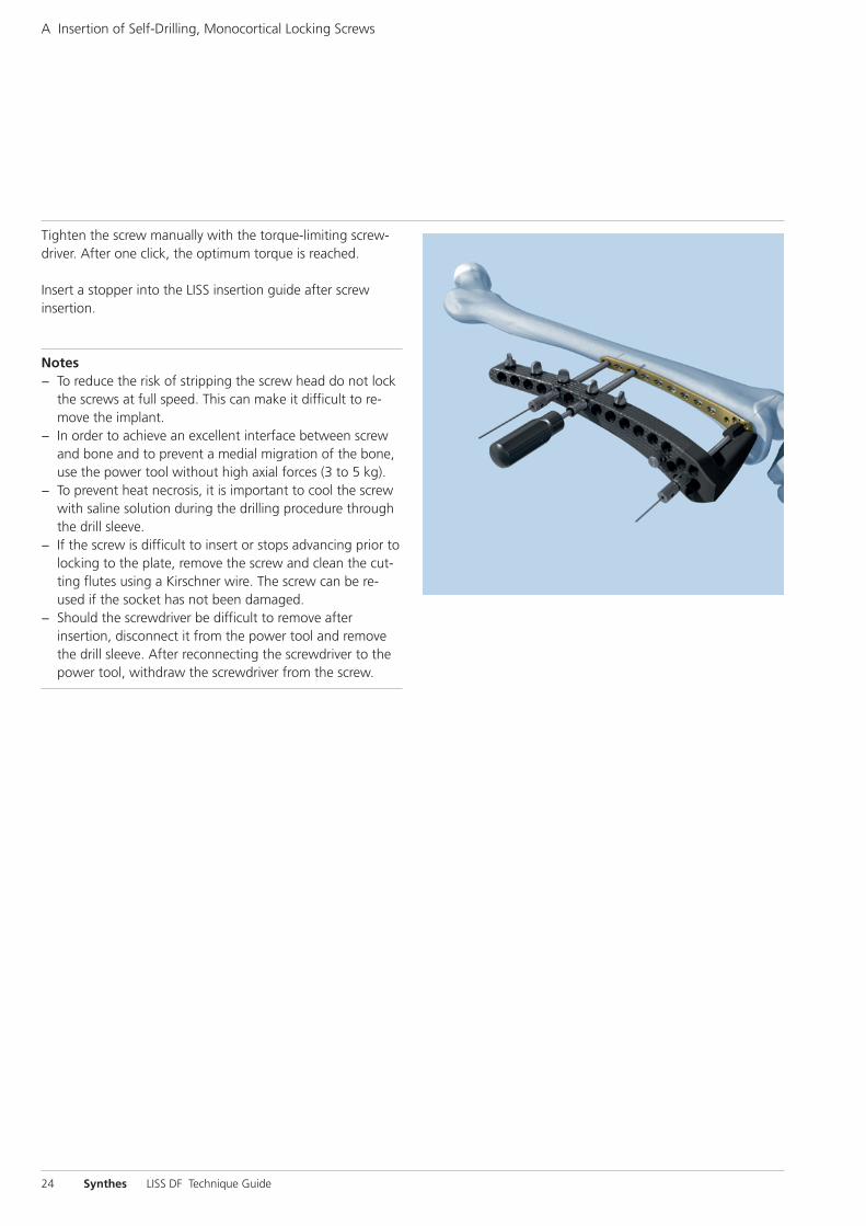
Tighten the screw manually with the torque-limiting screw-driver. After one click, the optimum torque is reached.
Insert a stopper into the LISS insertion guide after screw insertion.
Notes− To reduce the risk of stripping the screw head do not lock
the screws at full speed. This can make it difficult to re-move the implant.
− In order to achieve an excellent interface between screwand bone and to prevent a medial migration of the bone,use the power tool without high axial forces (3 to 5 kg).
− To prevent heat necrosis, it is important to cool the screwwith saline solution during the drilling procedure throughthe drill sleeve.
− If the screw is difficult to insert or stops advancing prior tolocking to the plate, remove the screw and clean the cut-ting flutes using a Kirschner wire. The screw can be re-used if the socket has not been damaged.
− Should the screwdriver be difficult to remove afterinsertion, disconnect it from the power tool and removethe drill sleeve. After reconnecting the screwdriver to thepower tool, withdraw the screwdriver from the screw.
A Insertion of Self-Drilling, Monocortical Locking Screws

Synthes 25
1Make stab incision
Instruments
324.022 Drill Sleeve for LISS Insertion Guide
324.027 Trocar, length 162 mm, for No. 324.022
Make a stab incision and insert the trocar through the drillsleeve for LISS insertion guide.
2Predrill screw hole
Instruments
324.007 Drill Sleeve 7.2/4.3, length 130 mm
310.423 Drill Bit � 4.3 mm, length 280 mm
Remove the trocar and thread the drill sleeve 7.2/4.3 into theplate hole through the drill sleeve for LISS insertion guide.
Carefully drill the screw hole using the 4.3 mm drill bit.
B Insertion of Self-Tapping, BicorticalLocking Screws

26 Synthes LISS DF Technique Guide
3Determine screw length
The length of the condylar screws can be deduced from thetable on page 9.
For screws in the diaphyseal region
Slide the stop ring down to the drill sleeve to make readingeasier.
Read the drilled depth directly from the laser mark on thedrill bit. Remove both drill bit and drill sleeve 7.2/4.3.
Note: Replacement stop rings can be ordered from the localSynthes representative.
Option: The insertion of the initial screw tends to push thebone medially, especially in the case of dense bone and/orunstable reductions. The pulling device helps to solve thisproblem (see page 32).
B Insertion of Self-Tapping, Bicortical Locking Screws
Synthes 27
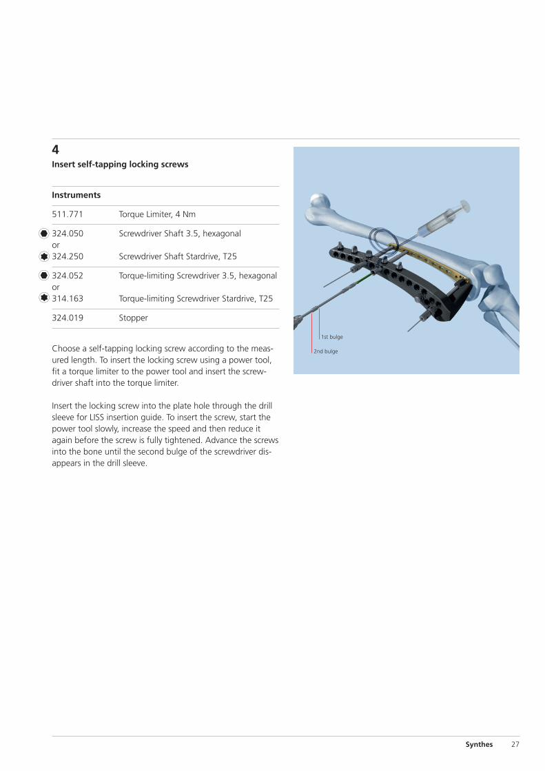
4Insert self-tapping locking screws
Instruments
511.771 Torque Limiter, 4 Nm
324.050 Screwdriver Shaft 3.5, hexagonalor324.250 Screwdriver Shaft Stardrive, T25
324.052 Torque-limiting Screwdriver 3.5, hexagonalor314.163 Torque-limiting Screwdriver Stardrive, T25
324.019 Stopper
Choose a self-tapping locking screw according to the meas-ured length. To insert the locking screw using a power tool,fit a torque limiter to the power tool and insert the screw-driver shaft into the torque limiter.
Insert the locking screw into the plate hole through the drillsleeve for LISS insertion guide. To insert the screw, start thepower tool slowly, increase the speed and then reduce itagain before the screw is fully tightened. Advance the screwsinto the bone until the second bulge of the screwdriver dis-appears in the drill sleeve.
2nd bulge
1st bulge

28 Synthes LISS DF Technique Guide
Tighten the screw manually with the torque-limiting screw-driver. The optimum torque is reached after one click.
Insert a stopper into the LISS insertion guide after screw insertion.
Notes− To reduce the risk of stripping the screw head do not lock
the screws at full speed. This can make it difficult to remove the implant.
– For long screws and thick cortical bone, ensure sufficientcooling during insertion.
B Insertion of Self-Tapping, Bicortical Locking Screws
Option: Manual insertion
Instruments
324.052 Torque-limiting Screwdriver 3.5, hexagonalor314.163 Torque-limiting Screwdriver Stardrive, T25
324.019 Stopper
Insert and lock the screw with the torque-limiting screwdriverthrough the drill sleeve for LISS insertion guide.
Insert a stopper into the LISS insertion guide after screw insertion.
Synthes 29
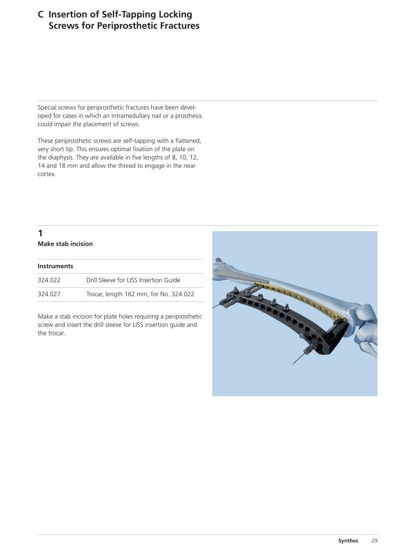
Special screws for periprosthetic fractures have been devel-oped for cases in which an intramedullary nail or a prosthesiscould impair the placement of screws.
These periprosthetic screws are self-tapping with a flattened,very short tip. This ensures optimal fixation of the plate onthe diaphysis. They are available in five lengths of 8, 10, 12,14 and 18 mm and allow the thread to engage in the nearcortex.
C Insertion of Self-Tapping LockingScrews for Periprosthetic Fractures
1Make stab incision
Instruments
324.022 Drill Sleeve for LISS Insertion Guide
324.027 Trocar, length 162 mm, for No. 324.022
Make a stab incision for plate holes requiring a periprostheticscrew and insert the drill sleeve for LISS insertion guide andthe trocar.

30 Synthes LISS DF Technique Guide
2Predrill screw hole
Instruments
324.007 Drill Sleeve 7.2/4.3, length 130 mm
310.423 Drill Bit � 4.3 mm, length 280 mm
Remove the trocar and thread the drill sleeve 7.2/4.3 into theplate hole through the drill sleeve for LISS insertion guide.
Use the drill bit to pre-drill the bone under image intensifiercontrol. Drill as close to the prosthesis or intramedullary implant as possible to allow for the placement of the longestperiprosthetic screw possible.
3Determine screw length
Slide the stop ring down to the drill sleeve to make readingeasier.
Read the drilled depth directly from the laser mark on thedrill bit. Remove both drill bit and drill sleeve 7.2/4.3.
Note: Replacement stop rings can be ordered from the localSynthes representative.
C Insertion of Self-Tapping Locking Screws for PeriprostheticFractures

Synthes 31
4Insert self-tapping locking screws for periprostheticfractures
Instruments
324.052 Torque-limiting Screwdriver 3.5, hexagonalor314.163 Torque-limiting Screwdriver Stardrive, T25
324.019 Stopper
Choose a periprosthetic screw according to the measuredlength. Insert and lock the screw with the torque-limitingscrewdriver through the drill sleeve for LISS insertion guide.
Insert a stopper into the LISS insertion guide after screw insertion.
Notes– If the measured drill depth is shorter than 8 mm, do not
use periprosthetic screws.– Never place a screw which is longer than the measured
length, as this will result in stripping of the thread in the bone and loss of screw anchoring.

32 Synthes LISS DF Technique Guide
Instrument
324.033 Pulling Device, length 240 mm
324.022 Drill Sleeve for LISS Insertion Guide
The insertion of the initial screw tends to push the bone medially, especially in case of dense bone and/or unstable reductions. The pulling device helps to solve this problem.
Insert the pulling device without the knurled nut through thedrill sleeve into the neighbouring hole of the first permanentscrew.
Stop the power tool before the entire screw length of thepulling device is inserted.
Remove the power tool and the drill sleeve.
Screwing the knurled nut onto the pulling device allows thebone to pull towards the plate. Since the tip of this instru-ment has a diameter of 4.0 mm, replacing it with a 5.0 mmlocking screw still ensures good purchase in the bone.
Note: It is important to monitor the advance of the screw tipcarefully when inserting the pulling device. Stop the powertool before the pulling device is seated on the plate. Failureto do so may result in stripping the thread in the bone.
Option: Pulling Device (“Whirly Bird”)

Synthes 33
Implant Removal
Instruments
324.011 LISS Insertion Guide for Distal Femur, leftor324.012 LISS Insertion Guide for Distal Femur, right
324.043 Fixation Bolt for LISS Insertion Guide
324.022 Drill Sleeve for LISS Insertion Guide
324.044 Stabilization Bolt for LISS Insertion Guide
324.027 Trocar, length 162 mm, for No. 324.022
324.050 Screwdriver Shaft 3.5, hexagonal, length 158 mm
or324.250 Screwdriver Shaft Stardrive, T25, length
158 mm
324.052 Torque-limiting Screwdriver 3.5, hexagonalor314.163 Torque-limiting Screwdriver Stardrive, T25
Remove the implant only after complete consolidation of thefracture. Remove it in reverse order to the implantation.
First, make the incision for the insertion guide in the path ofthe old scar, and mount the insertion guide (see step 1 onpage 16).
Make stab incisions and use the torque-limiting screwdriverto unlock all screws manually. In a second step, completelyremove all screws with a power tool.

34 Synthes LISS DF Technique Guide
Option: Clean screw heads with cleaning instruments
Instruments
324.053 Cleaning Instrument foror Screw Head, hexagonal324.253 Cleaning Instrument for
Screw Head Stardrive, T25
The cleaning instrument helps to clean the recess of thescrew heads. After placing the drill sleeve, insert the cleaninginstrument carefully. Insert the stiletto with threaded tip andturn clockwise. Remove the cleaning instrument. Unlock allscrews manually with the torque-limiting screwdriver. In asecond step, completely remove all screws with a power tool.
If the screws cannot be removed with the screwdriver, pleaseconsult the separate Synthes publication "Screw ExtractionSet. Instruments for removing Synthes screws." (Art. No.036.000.918), which explains in detail how screws with adamaged recess as well as how broken and jammed screwscan be removed.
After removal of all screws, remove the plate. Should theplate remain stuck when all screws have been removed, takethe insertion guide away and use the fixation bolt to loosenthe plate.
Note: Never use the cleaning instrument as a screwdriver.
Implant Removal

Correct placement
Compromisedscrew purchase
Synthes 35
Tips
If the reduction of the fracture causes difficulties, insert aSchanz screw antero-medially in the distal fragment, and usethe screw as a joystick. The insertion of a Schanz screw orpulling device into the proximal fragment can also be verybeneficial. Should it still be impossible to perform a correctreduction, improve the access by enlarging the soft-tissueopening.
Bending and twisting of the plate is not recommended as itmay result in a misalignment between the holes of the inser-tion guide and the corresponding plate holes.
Should the plate lie too ventral or too dorsal, the screws can-not be centred in the medullary canal. This position maycompromise screw purchase (see illustration).
Both screwdriver shaft and torque-limiting screwdriver areequipped with a self-holding mechanism. Apply slight pres-sure on pick-up to ensure that the screwdriver shaft pene-trates the recess of the screw head.
Should the screwdriver be difficult to remove after insertion,disconnect it from the power tool and remove the drillsleeve. After reconnecting the screwdriver to the power tool,withdraw the screwdriver from the screw.
Standard 4.5 mm cortex screws can be used through the in-sertion guide if required. Note that cortex screws cannot beinserted through the drill sleeve for LISS insertion guide.
Hole A serves to lock the insertion guide to the implant. Thishole cannot be used for the insertion of a screw as long asthe fixation bolt is attached. If a screw has to be inserted inhole A, remove the fixation bolt – with the stabilization boltstill in place – and attach it in an adjacent hole. Place the drillsleeve in hole A (pre-drill if necessary) and insert the appro-priate screw. If all holes are occupied by a screw, the screw inhole A can be inserted by free-hand technique. Use the di-rection given by the fixation bolt prior to removal of the in-sertion guide to determine the correct direction for insertion.
To ensure stability of the construct, the most proximal screwshould be inserted last, just before removing the insertion
guide. Remove the stabilization bolt and insert the screwthrough the drill sleeve.
If hole A is unoccupied, it must be closed with a Screw HoleInsert (422.390) to facilitate the application of the insertionguide for removing the implant.

36 Synthes LISS DF Technique Guide
Instruments for Minimally InvasiveOsteosynthesis
Hohmann Retractor HolderThe Hohmann retractor holder was developed to supportminimally invasive, percutaneous plate osteosynthesis. Itsunique design enables the easy and reliable percutaneous in-sertion of plates. These characteristics make the Hohmannretractor holder the ideal instrument for use in combinationwith modern implant systems such as LCP and LISS.
− The Hohmann retractor holder allows better visualizationof the inserted plate.
− Serves as a guide for the inserted plate.− Ensures that the inserted plate is centered on the bone.
For additional information see the separate Synthes publication on the Hohmann retractor holder(Art. No. 036.000.219).
Soft Tissue RetractorThe offset blade facilitates easy preparation of the epipere-osteal cavity for percutaneous plate insertion.
− Adjustable blade for free choice of insertion angle andblade length
− Available in two sizes: for small and large fragment plates
For additional information see the separate Synthes publica-tion on the Soft tissue retractor (Art. No. 036.000.127).

Synthes 37
Implants
LCP DF 4.5/5.0
Stainless steel Titanium Holes Length (mm)
222.250 422.250 5 156 right
222.252 422.252 7 196 right
222.254 422.254 9 236 right
222.256 422.256 11 276 right
222.258 422.258 13 316 right
222.251 422.251 5 156 left
222.253 422.253 7 196 left
222.255 422.255 9 236 left
222.257 422.257 11 276 left
222.259 422.259 13 316 left
All plates are available nonsterile and sterile packed.For sterile implants add suffix S to the article number.

38 Synthes LISS DF Technique Guide
Locking Screws � 5.0 mm
Hex Stardrive
X13.414 – X12.251 – self-drilling,X13.490 X12.267 length 14 – 90 mm
X13.314 – X12.201 – self-tapping,X13.390 X12.227 length 14 – 90 mm
0X.221.458 0X.221.508 for periprosthetic0X.221.460 0X.221.510 fractures,0X.221.462 0X.221.512 self-tapping,X22.402 0X.221.514 length 8 – 18 mmX22.404 0X.221.518
X = 2: stainless steelX = 4: TAN
422.390 Screw Hole Insert � 5.0 mm
All screws are available nonsterile and sterile packed. Forsterile implants add suffix S to the article number.

Synthes 39
Instruments
324.011 LISS Insertion Guide for Distal Femur, left,radiolucent
324.012 LISS Insertion Guide for Distal Femur, right,radiolucent
324.043 Fixation Bolt for LISS Insertion Guide,length 151 mm
321.170 Pin Wrench � 4.5 mm, length 120 mm
324.022 Drill Sleeve for LISS Insertion Guide,length 130 mm
324.044 Stabilization Bolt for LISS Insertion Guide,length 156 mm
324.027 Trocar, length 162 mm, for No. 324.022
324.033 Pulling Device � 4.0 mm, length 240 mm,for LISS
310.423 Drill Bit � 4.3 mm, length 280 mm, for LISS

40 Synthes LISS DF Technique Guide
Instruments
324.052 Torque-limiting Screwdriver 3.5, self-holding, for Locking Screws � 5.0 mm
314.163 Torque-limiting Screwdriver Stardrive, T25,self-holding, for Locking Screws � 5.0 mm
324.050 Screwdriver Shaft 3.5, hexagonal, length 158 mm
324.250 Screwdriver Shaft Stardrive, T25, length 158 mm
324.055 Centering Sleeve for Kirschner Wire,length 161 mm, for No. 324.022
324.019 Stopper for LISS Insertion Guide
324.056 X-ray Calibrator, length 50 mm
324.053 Cleaning Instrument for Screw Head,length 202 mm
324.253 Cleaning Instrument for Screw HeadStardrive, T25, length 202 mm

Synthes 41
Optional instruments
324.048 Aiming Device for Kirschner Wires, for LISS Insertion Guide
324.034 Centering Sleeve for Kirschner Wire,length 184 mm, for No. 324.048
292.699 Kirschner Wire � 2.0 mm with threadedtip, length 280 mm, Stainless Steel
324.037 LISS Measuring Device for Kirschner Wires� 2.0 mm, length 121 mm, for No. 292.699
324.007 Drill Sleeve 7.2/4.3, length 130 mm, for LISS Periprosthetic Screws
42 Synthes LISS DF Technique Guide
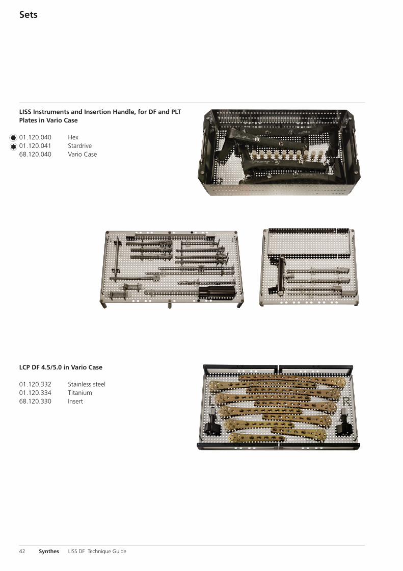
LISS Instruments and Insertion Handle, for DF and PLTPlates in Vario Case
01.120.040 Hex01.120.041 Stardrive68.120.040 Vario Case
LCP DF 4.5/5.0 in Vario Case
01.120.332 Stainless steel01.120.334 Titanium68.120.330 Insert
Sets

Synthes 43
Locking Screws � 5.0 mm and Standard Screws� 4.5/6.5 mm in Sterilizing Tray
Hex Stardrive
Stainless steel 01.200.011 01.200.013
Titanium 01.200.012 01.200.014
300.610 Sterilizing Tray

44 Synthes LISS DF Technique Guide
Bibliography
Fankhauser F et al. (2004) Minimal-invasive treatment of dis-tal femoral fractures with the LISS (Less Invasive StabilizationSystem). Acta Orthop Scand 75 (1):56–60
Haas NP et al. (1997) LISS – ein neuer Fixateur intern für distale Femurfrakturen [LISS – a new internal fixator for distalfemoral fractures]. OP Journal 13:340–344
Hockertz TJ et al. (1999) Die Versorgung von periprotheti -schen Femurfrakturen bei liegender Kniegelenkprothese mitdem LIS-System [Use of the LISS to treat periprostheticfemoral fractures with implanted knee prosthesis]. Der Unfallchirurg 10:811–814
Injury (2001) Int. J. Care Injured 32:S-C
Kobbe P, Hockertz TJ, Reilmann H (2006) PeriprothetischeFrakturen [Periprosthetic Fractures]. OP Journal 22:22–26
Schandelmaier P et al. (1999) LISS-Osteosynthese von dis-talen Femurfrakturen [LISS osteosynthesis of distal femoralfractures]. Trauma Berufskrankheiten 1:392–397
Schandelmaier P et al. (1999) Stabilisation of distal femurfractures using the LISS. Techniques in Orthopaedics14 (3):230–246
Schandelmaier P et al. (2000) Distale Femurfrakturen[Distal femoral fractures]. Unfallchirurg 70:428–436
Schandelmaier P et al. (2001) Internal Fixation of Distal Fe-mur Fractures with the Less Invasive Stabilizing System (LISS).Orthopedics and Traumatology 9:166–184
Schütz M et al. (2003) Revolution in plate osteosynthesis:new internal fixator systems. Journal of Orthopedic Science8:252–258


Synthes GmbHEimattstrasse 3CH-4436 Oberdorfwww.synthes.com 0123Presented by: 03
6.00
0.23
5 SE
_010
415
AE
3108
0016
©
05/
2008
Syn
thes
, Inc
. or
its a
ffili
ates
A
ll rig
hts
rese
rved
Sy
nthe
s, C
ompa
ct, L
CP,
Sta
rdriv
e an
d Va
rio C
ase
are
trad
emar
ks o
f Sy
nthe
s, In
c. o
r its
aff
iliat
es


