Liquid crystal Thermography - SRM Institute of Science … · · 2015-11-07Liquid crystal...
26
Liquid crystal Thermography • What are Thermochromic Liquid Crystals‐ – Thermochromic Liquid Crystals (TLC) are materials that change their reflected colour as a function of temperature when illuminated by white light. Hence, reflect visible light at a different wavelengths.
Transcript of Liquid crystal Thermography - SRM Institute of Science … · · 2015-11-07Liquid crystal...
Liquid crystal Thermography
• What are Thermochromic Liquid Crystals‐
– Thermochromic Liquid Crystals (TLC) are materials that change their reflected colour as a function of temperature when illuminated by white light. Hence, reflect visible light at a different wavelengths.
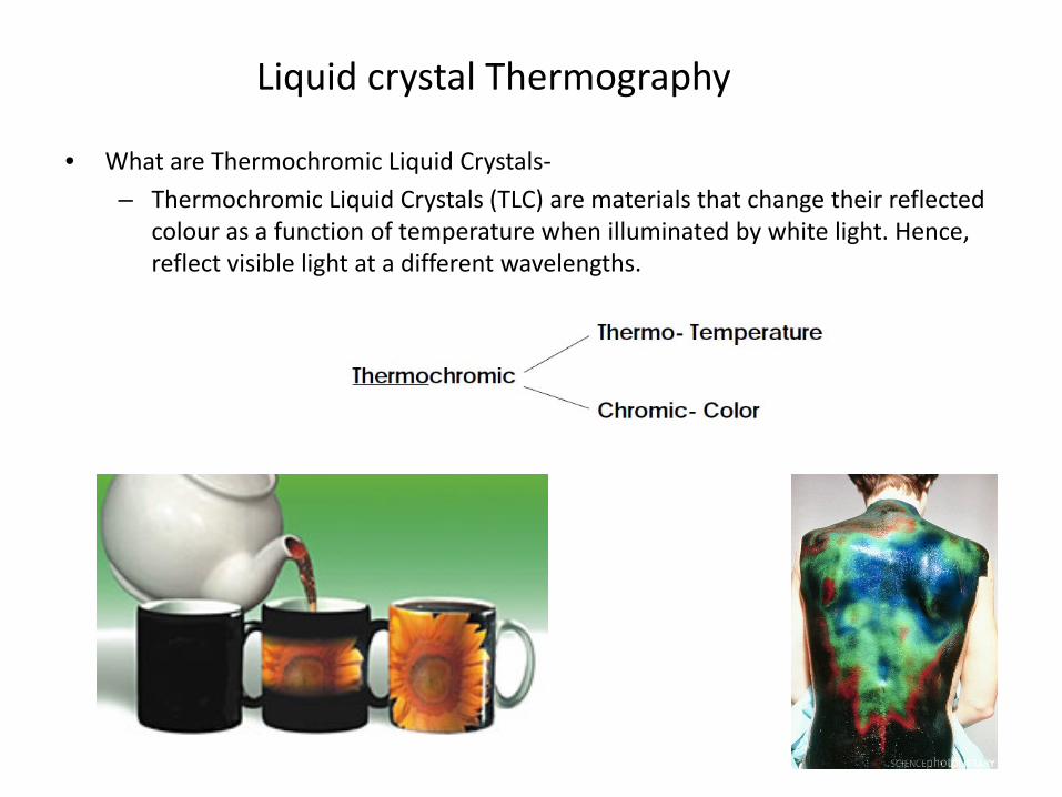
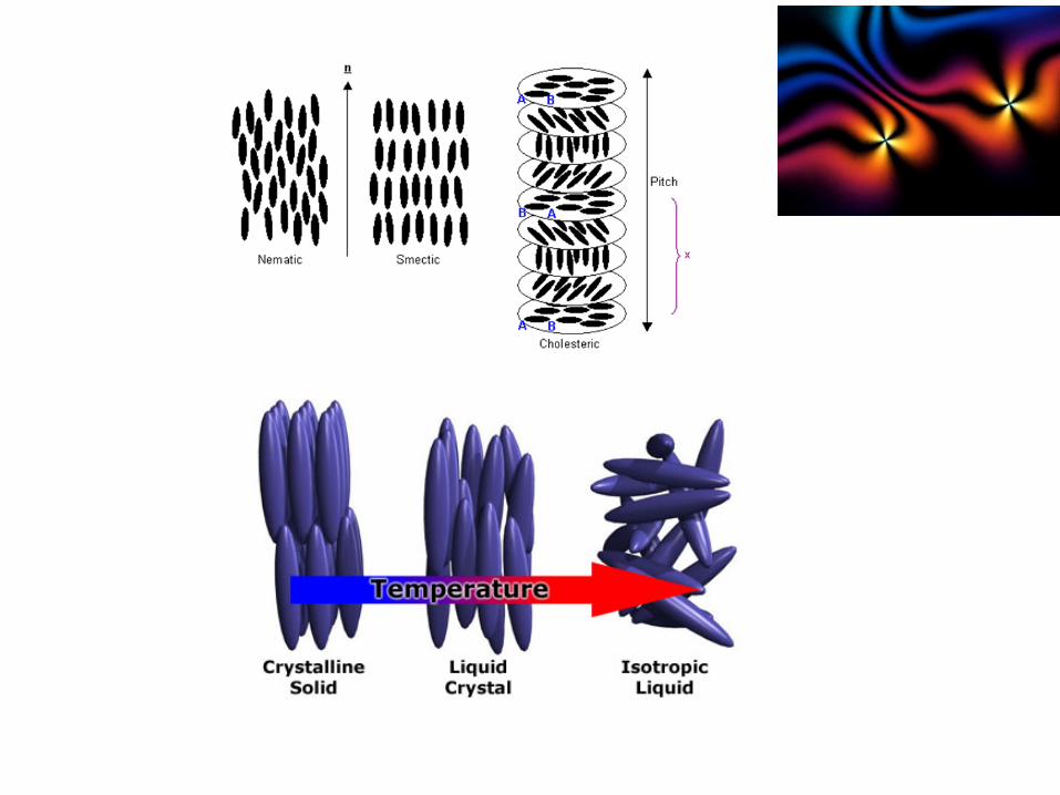
Liquid crystal Phases
• Thermotropic liquid crystals
– Thermotropic phases are those that occur in a certaintemperature range. If the temperature rise is too high, thermalmotion will destroy the delicate cooperative ordering of the LCphase, pushing the material into a conventional isotropic liquidphase. At too low temperature, most LC materials will form aconventional crystal
• Nematic phase
– rod‐shaped organic molecules have no positional order, but theyself‐align to have long‐range directional order with their long axesroughly parallel
• Smectic phases
– The smectic phases, which are found at lower temperatures thanthe nematic, form well‐defined layers that can slide over oneanother in a manner similar to that of soap
• Blue phases ‐ Regular three‐dimensional cubic structure
• Discotic phases ‐ Disk‐shaped LC molecules can orient themselvesin a layer‐like fashion
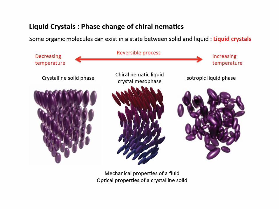
Liquid Crystals• Liquid crystal is a unique organic material which exists between the solid and
the isotropic liquid phase.
• In between these temperature limits, it shows a certain molecular structure that resembles the crystalline state.
• Here, the incident light is scattered selectively and forms the basis of temperature measurement.
• The material is in the amorphous solid phase below a certain temperature and a pure liquid beyond an upper limit.
• Liquid crystals possess a helical structure with a characteristic pitch
• The pitch length of the helix is in the range of the wavelength of visible light.
• The pitch length changes with an external stimulus such as temperature.
• In a second family of liquid crystals, the molecular structure responds to the applied shear stress.
• The fundamental chemical structure is unaffected by the external stimulus and a liquid crystal coating can respond repeatedly to the physical change and can be used reliably as a temperature sensor.
• Since the technique involves using a (white) light source for illumination and a detector for recording the scattered light, LCT classifies as an optical technique.
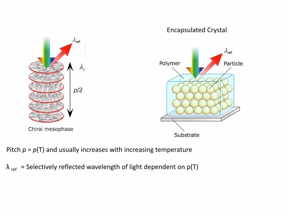
Pitch p = p(T) and usually increases with increasing temperature
λ ref = Selectively reflected wavelength of light dependent on p(T)
Encapsulated Crystal
Temperature• The lowest temperature where liquid crystals scatter visible light is called the event
temperature.
• At a temperature below the event temperature, liquid crystals will be in the solid state and will appear transparent.
• At a temperature above the clearing point temperature, it will enter the pure liquid state and will revert back to being transparent.
• Outside this range, the scattered light is negligible and, when viewed through a camera, the sheet would appear black.
• At the clearing point temperature, the helical pitch of the liquid crystals exceeds the wavelengths of visible light.
• The reflected colour spectrum of liquid crystals will vary continuously from the longer wavelengths (red) corresponding to event temperature to shorter wavelengths (blue) corresponding to the clearing point temperature.
• At intermediate temperatures, the surface would take on a green colour.
• Liquid crystals transmit a significant amount of the incident light with virtually no modification.
• Therefore, they are viewed against a non‐reflecting (black) background.
• This precaution prevents the transmitted light from getting reflected without adversely affecting the interpretation of selectively scattered light from the liquid crystals.
LC Material ‐ Types
Encapsulated — the liquid crystal material is encapsulated in a 5‐10 micronsphere suspended in a water based binder material‐‐ provides excellent protection. The micro‐encapsulation process offers chemical contaminant resistance and radiation protection.
Unencapsulated —the material is in its native form‐‐ susceptible to contamination, however, once applied, produces brilliant colours.
The liquid crystals can be either narrow band ‐ 1 or 2oC wide band formulation ‐ 5 and 30oC.
A colour/temperature designator describes the response of a typical liquid crystal chemical make up. This helps in selecting the liquid crystal composition for a particular application.
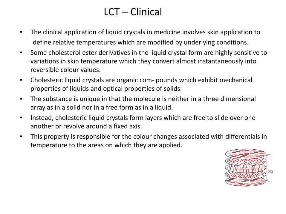
LCT – Clinical
• The clinical application of liquid crystals in medicine involves skin application to
define relative temperatures which are modified by underlying conditions.
• Some cholesterol ester derivatives in the liquid crystal form are highly sensitive to variations in skin temperature which they convert almost instantaneously into reversible colour values.
• Cholesteric liquid crystals are organic com‐ pounds which exhibit mechanical properties of liquids and optical properties of solids.
• The substance is unique in that the molecule is neither in a three dimensional array as in a solid nor in a free form as in a liquid.
• Instead, cholesteric liquid crystals form layers which are free to slide over one another or revolve around a fixed axis.
• This property is responsible for the colour changes associated with differentials in temperature to the areas on which they are applied.
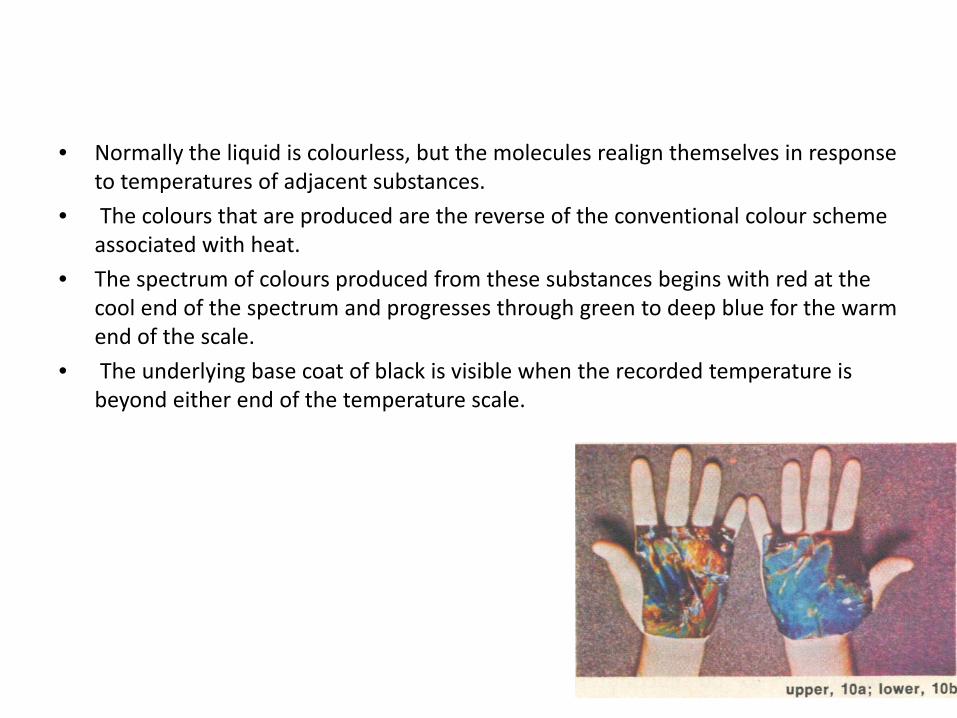
• Normally the liquid is colourless, but the molecules realign themselves in response to temperatures of adjacent substances.
• The colours that are produced are the reverse of the conventional colour scheme associated with heat.
• The spectrum of colours produced from these substances begins with red at the cool end of the spectrum and progresses through green to deep blue for the warm end of the scale.
• The underlying base coat of black is visible when the recorded temperature is beyond either end of the temperature scale.
Applications ‐ OrthopedicMaterials and Method:
• The technique of application begins with obtaining a black background before the cholesteric crystals are applied.
• This can be accomplished either by applying a plastic sheet, such as the Vidrape(types of adhesive) that is used in surgery, that has been painted black, or by direct application of a black paint to the area to be investigated.
• The clear liquid cholesteric crystal solution is then sprayed on the area.
• Because the crystals are affected by subsurface temperature, variations in color appear.
• The area investigated is then photographed.
• A 35 mm single reflex camera is used.
• The camera is equipped with a rotating polarizing filter.
• Strobe light (xenon) being a cool light is the most suitable light source.
• The flash unit, too, must be equipped with a polarizing filter, eliminating the reflections of the fatty cholesteric liquid crystals.
• The photographs are analysed for areas of relative temperature differential.
• In the evaluation of joint disease, a baseline study is carried out and then follow‐up studies are conducted at timely intervals to evaluate the effectiveness of the treatment program.
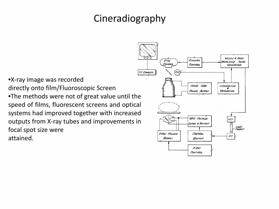
Cineradiography
•X‐ray image was recordeddirectly onto film/Fluoroscopic Screen•The methods were not of great value until thespeed of films, fluorescent screens and opticalsystems had improved together with increasedoutputs from X‐ray tubes and improvements infocal spot size wereattained.
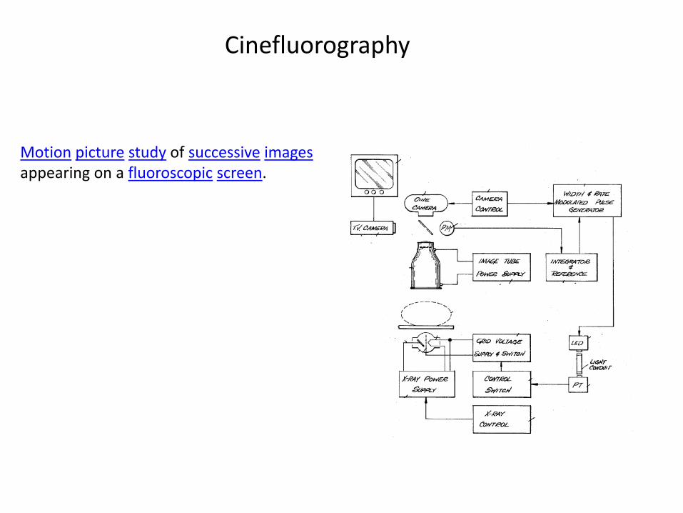
Cinefluorography
Motion picture study of successive imagesappearing on a fluoroscopic screen.
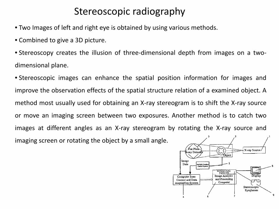
Stereoscopic radiography• Two Images of left and right eye is obtained by using various methods.
• Combined to give a 3D picture.
• Stereoscopy creates the illusion of three‐dimensional depth from images on a two‐
dimensional plane.
• Stereoscopic images can enhance the spatial position information for images and
improve the observation effects of the spatial structure relation of a examined object. A
method most usually used for obtaining an X‐ray stereogram is to shift the X‐ray source
or move an imaging screen between two exposures. Another method is to catch two
images at different angles as an X‐ray stereogram by rotating the X‐ray source and
imaging screen or rotating the object by a small angle.
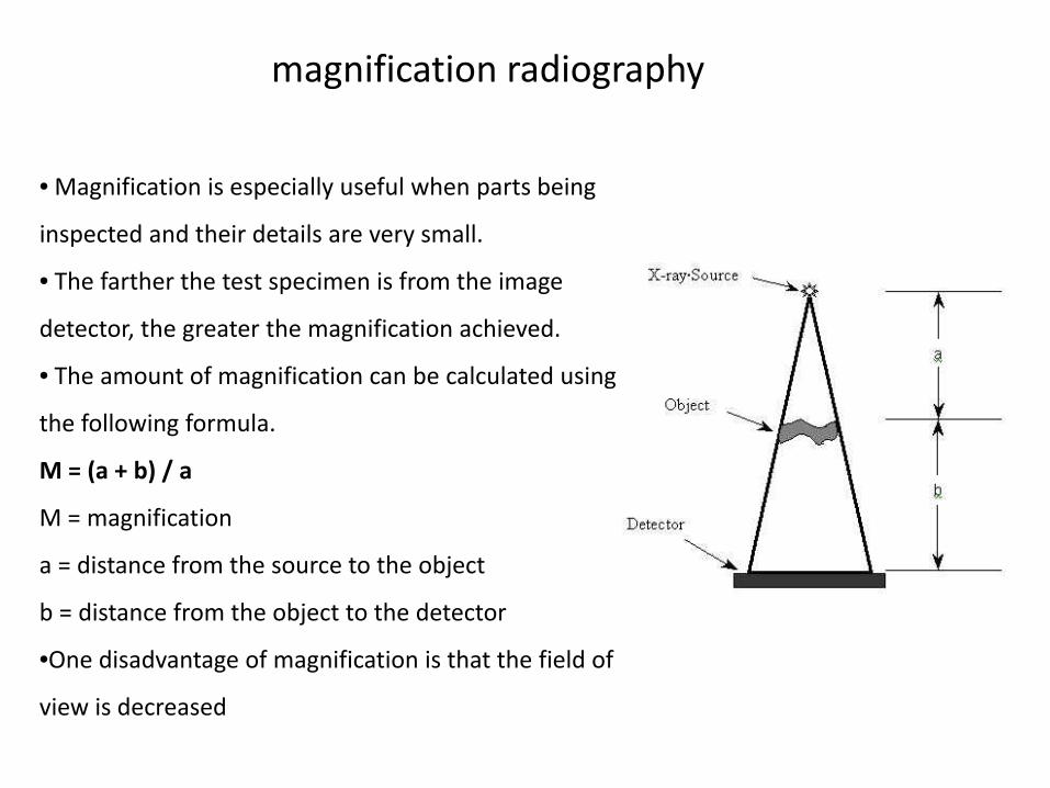
magnification radiography
• Magnification is especially useful when parts being
inspected and their details are very small.
• The farther the test specimen is from the image
detector, the greater the magnification achieved.
• The amount of magnification can be calculated using
the following formula.
M = (a + b) / a
M = magnification
a = distance from the source to the object
b = distance from the object to the detector
•One disadvantage of magnification is that the field of
view is decreased
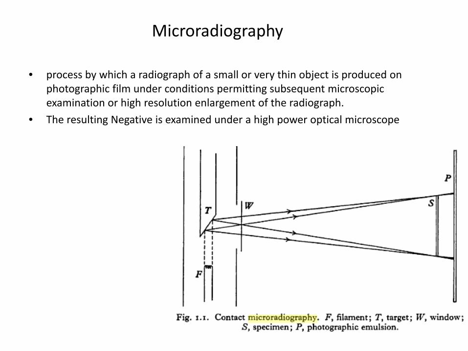
Microradiography
• process by which a radiograph of a small or very thin object is produced on photographic film under conditions permitting subsequent microscopic examination or high resolution enlargement of the radiograph.
• The resulting Negative is examined under a high power optical microscope
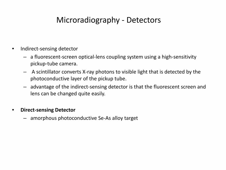
Microradiography ‐ Detectors
• Indirect‐sensing detector
– a fluorescent‐screen optical‐lens coupling system using a high‐sensitivity pickup‐tube camera.
– A scintillator converts X‐ray photons to visible light that is detected by the photoconductive layer of the pickup tube.
– advantage of the indirect‐sensing detector is that the fluorescent screen and lens can be changed quite easily.
• Direct‐sensing Detector
– amorphous photoconductive Se‐As alloy target
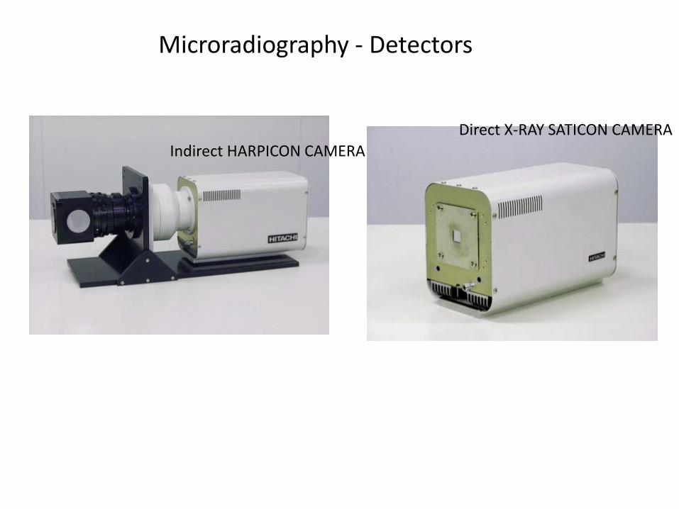
Microradiography ‐ Detectors
Indirect HARPICON CAMERADirect X‐RAY SATICON CAMERA
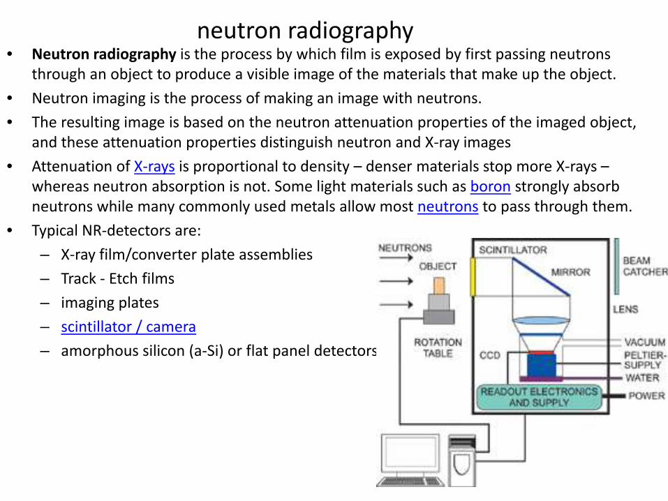
neutron radiography• Neutron radiography is the process by which film is exposed by first passing neutrons
through an object to produce a visible image of the materials that make up the object.
• Neutron imaging is the process of making an image with neutrons.
• The resulting image is based on the neutron attenuation properties of the imaged object, and these attenuation properties distinguish neutron and X‐ray images
• Attenuation of X‐rays is proportional to density – denser materials stop more X‐rays –whereas neutron absorption is not. Some light materials such as boron strongly absorb neutrons while many commonly used metals allow most neutrons to pass through them.
• Typical NR‐detectors are:
– X‐ray film/converter plate assemblies
– Track ‐ Etch films
– imaging plates
– scintillator / camera
– amorphous silicon (a‐Si) or flat panel detectors
Microwave Imaging
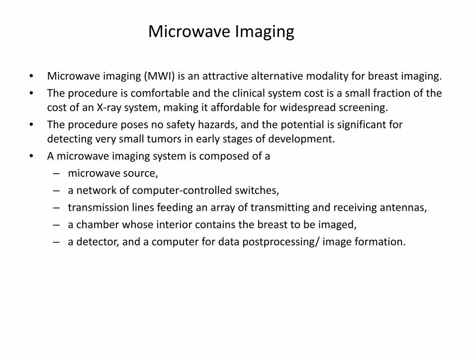
• Microwave imaging (MWI) is an attractive alternative modality for breast imaging.
• The procedure is comfortable and the clinical system cost is a small fraction of the cost of an X‐ray system, making it affordable for widespread screening.
• The procedure poses no safety hazards, and the potential is significant for detecting very small tumors in early stages of development.
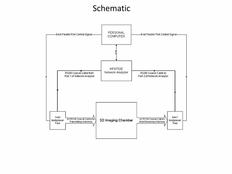
• A microwave imaging system is composed of a
– microwave source,
– a network of computer‐controlled switches,
– transmission lines feeding an array of transmitting and receiving antennas,
– a chamber whose interior contains the breast to be imaged,
– a detector, and a computer for data postprocessing/ image formation.
Schematic
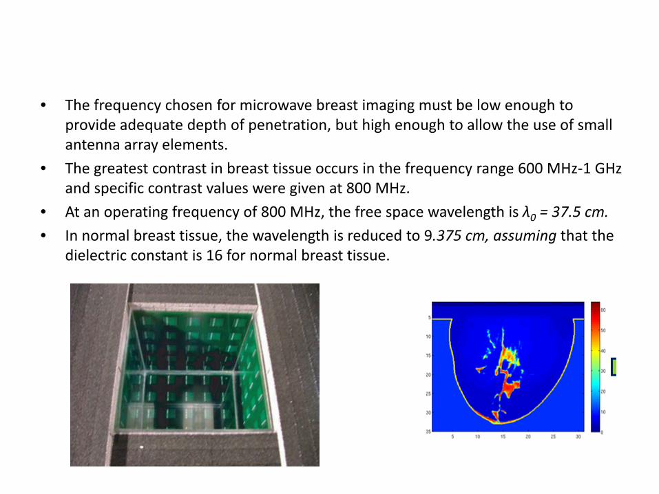
• The frequency chosen for microwave breast imaging must be low enough to provide adequate depth of penetration, but high enough to allow the use of small antenna array elements.
• The greatest contrast in breast tissue occurs in the frequency range 600 MHz‐1 GHz and specific contrast values were given at 800 MHz.
• At an operating frequency of 800 MHz, the free space wavelength is λ0 = 37.5 cm.
• In normal breast tissue, the wavelength is reduced to 9.375 cm, assuming that the dielectric constant is 16 for normal breast tissue.
• Three different methods of microwave breast imaging methods are discussed brieflybelow
• Passive microwave Imaging : Passive methods incorporate radiometers to measuretemperature differences in the breast, detecting tumours based on their increasedtemperature compared to normal tissue.
• Hybrid Microwave‐Acoustic Imaging: Hybrid: methods use microwave energy to selectand rapidly heat tumours and ultrasound transducers to detect pressure wavesgenerated by the expansion of the heated tissues. Due to higher conductivity ofmalignant breast tissue, more energy is deposited in tumours, resulting in selectiveheating of these lesions. The tumours expand and generate pressure waves which aredetected by ultrasound transducers.
• Active Microwave Imaging: Active methods involve illuminating the breast with microwaves and then measuring transmitted or reflected microwave signals, and forming images with these data.
Microwave Antennas employed in Medical Imaging
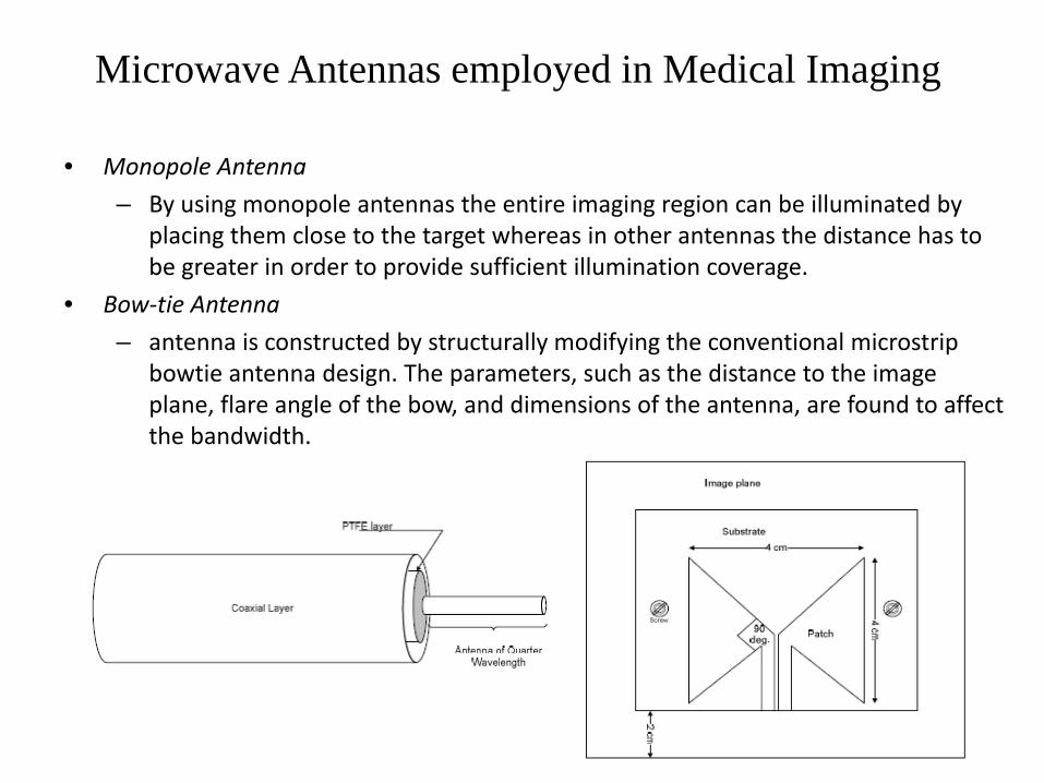
• Monopole Antenna
– By using monopole antennas the entire imaging region can be illuminated by placing them close to the target whereas in other antennas the distance has to be greater in order to provide sufficient illumination coverage.
• Bow‐tie Antenna
– antenna is constructed by structurally modifying the conventional microstrip bowtie antenna design. The parameters, such as the distance to the image plane, flare angle of the bow, and dimensions of the antenna, are found to affect the bandwidth.
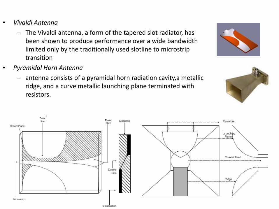
• Vivaldi Antenna
– The Vivaldi antenna, a form of the tapered slot radiator, has been shown to produce performance over a wide bandwidth limited only by the traditionally used slotline to microstrip transition
• Pyramidal Horn Antenna
– antenna consists of a pyramidal horn radiation cavity,a metallic ridge, and a curve metallic launching plane terminated with resistors.
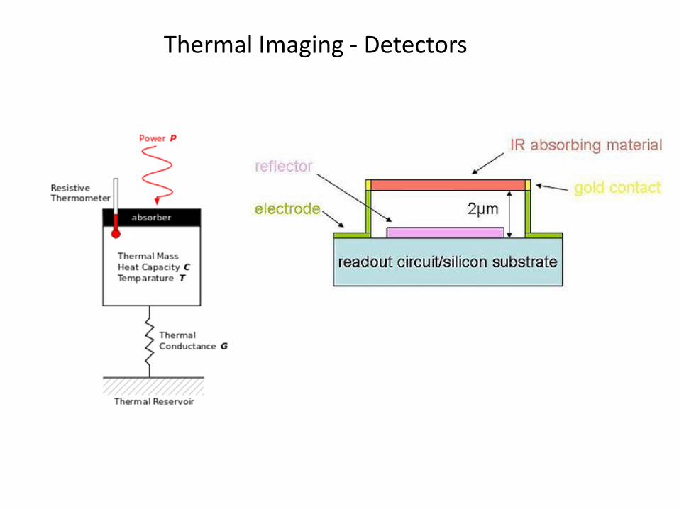
Thermal Imaging ‐ Detectors