LinkRunner AT 1000/2000 -...
36
January 2012 © 2012 Fluke Corporation. All product names are trademarks of their respective companies. LinkRunner ™ AT 1000/2000 Network Auto-Tester Users Manual
Transcript of LinkRunner AT 1000/2000 -...
January 2012© 2012 Fluke Corporation.All product names are trademarks of their respective companies.
LinkRunner™ AT 1000/2000Network Auto-Tester
Users Manual
LIMITED WARRANTY AND LIMITATION OF LIABILITYEach Fluke Networks product is warranted to be free from defects in material and workmanship under normal use and service. The warranty period for the mainframe is one year and begins on the date of purchase. Parts, accessories, product repairs and services are warranted for 90 days, unless otherwise stated. Ni-Cad, Ni-MH and Li-Ion batteries, cables or other peripherals are all considered parts or accessories. The warranty extends only to the original buyer or end user customer of a Fluke Networks authorized reseller, and does not apply to any product which, in Fluke Networks’ opinion, has been misused, abused, altered, neglected, contaminated, or damaged by accident or abnormal conditions of operation or handling. Fluke Networks warrants that software will operate substantially in accordance with its functional specifications for 90 days and that it has been properly recorded on non-defective media. Fluke Networks does not warrant that software will be error free or operate without interruption.Fluke Networks authorized resellers shall extend this warranty on new and unused products to end-user customers only but have no authority to extend a greater or different warranty on behalf of Fluke Networks. Warranty support is available only if product is purchased through a Fluke Networks authorized sales outlet or Buyer has paid the applicable international price. Fluke Networks reserves the right to invoice Buyer for importation costs of repair/replacement parts when product purchased in one country is submitted for repair in another country.Fluke Networks warranty obligation is limited, at Fluke Networks option, to refund of the purchase price, free of charge repair, or replacement of a defective product which is returned to a Fluke Networks authorized service center within the warranty period.To obtain warranty service, contact your nearest Fluke Networks authorized service center to obtain return authorization information, then send the product to that service center, with a description of the difficulty, postage and insurance prepaid (FOB destination). Fluke Networks assumes no risk for damage in transit. Following warranty repair, the product will be returned to Buyer, transportation prepaid (FOB destination). If Fluke Networks determines that failure was caused by neglect, misuse, contamination, alteration, accident or abnormal condition of operation or handling, or normal wear and tear of mechanical components, Fluke Networks will provide an estimate of repair costs and obtain authorization before commencing the work. Following repair, the product will be returned to the Buyer transportation prepaid and the Buyer will be billed for the repair and return transportation charges (FOB Shipping point).THIS WARRANTY IS BUYER’S SOLE AND EXCLUSIVE REMEDY AND IS IN LIEU OF ALL OTHER WARRANTIES, EXPRESS OR IMPLIED, INCLUDING BUT NOT LIMITED TO ANY IMPLIED WARRANTY OR MERCHANTABILITY OR FITNESS FOR A PARTICULAR PURPOSE. FLUKE NETWORKS SHALL NOT BE LIABLE FOR ANY SPECIAL, INDIRECT, INCIDENTAL OR CONSEQUENTIAL DAMAGES OR LOSSES, INCLUDING LOSS OF DATA, ARISING FROM ANY CAUSE OR THEORY.Since some countries or states do not allow limitation of the term of an implied warranty, or exclusion or limitation of incidental or consequential damages, the limitations and exclusions of this warranty may not apply to every buyer. If any provision of this Warranty is held invalid or unenforceable by a court or other decision-maker of competent jurisdiction, such holding will not affect the validity or enforceability of any other provision.
4/04
Fluke NetworksPO Box 777Everett, WA 98206-0777USA
SOFTWARE NOTICEThis product uses freeRTOS v6.0.5 software. For more information on freeRTOS, go to http://www.freertos.org. The software license statement and files that contain the binary and source code for freeRTOS v6.0.5 are on the LinkRunner AT CD supplied with this product.Copyright 2010 Real Time Engineering Ltd.
Copyright 1998 Regents of the University of California. All rights reserved.Redistribution and use in source and binary forms, with or without modification, are permitted provided that the following conditions are met:Redistributions of source code must retain the above copyright notice, this list of conditions and the following disclaimer.Redistributions in binary form must reproduce the above copyright notice, this list of conditions and the following disclaimer in the documentation and/or other materials provided with the distribution.Neither the name of the University of California, Berkeley nor the names of its contributors may be used to endorse or promote products derived from this software without specific prior written permission.THIS SOFTWARE IS PROVIDED BY THE COPYRIGHT HOLDERS AND CONTRIBUTORS "AS IS" AND ANY EXPRESS OR IMPLIED WARRANTIES, INCLUDING, BUT NOT LIMITED TO, THE IMPLIED WARRANTIES OF MERCHANTABILITY AND FITNESS FOR A PARTICULAR PURPOSE ARE DISCLAIMED. IN NO EVENT SHALL THE COPYRIGHT HOLDER OR CONTRIBUTORS BE LIABLE FOR ANY DIRECT, INDIRECT, INCIDENTAL, SPECIAL, EXEMPLARY, OR CONSEQUENTIAL DAMAGES (INCLUDING, BUT NOT LIMITED TO, PROCUREMENT OF SUBSTITUTE GOODS OR SERVICES; LOSS OF USE, DATA, OR PROFITS; OR BUSINESS INTERRUPTION) HOWEVER CAUSED AND ON ANY THEORY OF LIABILITY, WHETHER IN CONTRACT, STRICT LIABILITY, OR TORT (INCLUDING NEGLIGENCE OR OTHERWISE) ARISING IN ANY WAY OUT OF THE USE OF THIS SOFTWARE, EVEN IF ADVISED OF THE POSSIBILITY OF SUCH DAMAGE.

i
Contents
Title PageIntroduction .......................................................................................................................................................................... 1Registering Your Product ..................................................................................................................................................... 1The Fluke Networks Knowledge Base ................................................................................................................................. 1Contact Fluke Networks ....................................................................................................................................................... 2Safety Information ................................................................................................................................................................ 2Unpacking ............................................................................................................................................................................. 3
LR-AT (1000 and 2000 Models) ..................................................................................................................................... 3Cleaning the Tester ........................................................................................................................................................ 3
Physical Features ................................................................................................................................................................... 4The Home Screen .................................................................................................................................................................. 6Battery Charging and Life .................................................................................................................................................... 7Common Questions LR-AT Can Solve ................................................................................................................................... 8Saving a Report ..................................................................................................................................................................... 10Set Up the Tester ................................................................................................................................................................... 11
IP Configuration ............................................................................................................................................................. 11VLAN/MAC Configuration ............................................................................................................................................. 12
LinkRunner AT 1000/2000 Network Auto-TesterUsers Manual
ii
AutoTest Configuration ................................................................................................................................................. 12PoE Configuration .......................................................................................................................................................... 13Connect Configuration .................................................................................................................................................. 13General Configuration ................................................................................................................................................... 14Reflector Configuration (LR-AT 2000 Model) ............................................................................................................... 14LinkRunner Information ................................................................................................................................................ 15Manage Files ................................................................................................................................................................... 16Restore Factory Defaults ................................................................................................................................................ 17Firmware Update ........................................................................................................................................................... 18Transfer Saved Profiles to/from LinkRunner Manager ................................................................................................ 19Set Language .................................................................................................................................................................. 19
Using AutoTest, Switch, and Cable Test ............................................................................................................................... 19Using AutoTest ............................................................................................................................................................... 19Using the Nearest Switch Test ....................................................................................................................................... 21Using the Cable Test ...................................................................................................................................................... 21Using PoE Feature .......................................................................................................................................................... 22Using the Reflector Feature (LR-AT 2000 only) ............................................................................................................ 23Using the Fiber Connection ........................................................................................................................................... 23
Maintenance .......................................................................................................................................................................... 24Options and Accessories ........................................................................................................................................................ 25Specifications ......................................................................................................................................................................... 26
Environmental Specifications ........................................................................................................................................ 26General Specifications .................................................................................................................................................... 27LinkRunner Manager Software ..................................................................................................................................... 28
iii
List of Figures
Figure Page1. Physical Features ................................................................................................................................................... 42. The Home Screen ................................................................................................................................................. 63. How to Remove the Battery................................................................................................................................. 74. Tools Menu............................................................................................................................................................ 115. IP Configuration Screen........................................................................................................................................ 116. VLAN/MAC Configuration Screen ........................................................................................................................ 127. AutoTest Configuration Screen............................................................................................................................ 128. PoE Configuration Screen..................................................................................................................................... 139. Connect Configuration Screen ............................................................................................................................. 1310. General Configuration Screen.............................................................................................................................. 1411. Reflector Settings Screen...................................................................................................................................... 1412. Reflector Default Configuration Screen .............................................................................................................. 1513. LinkRunner Information Screen ........................................................................................................................... 1614. AutoTest Configuration Screen............................................................................................................................ 2015. AutoTest Results Screen........................................................................................................................................ 2016. Expanding Test Results ......................................................................................................................................... 2017. Nearest Switch Results .......................................................................................................................................... 21
LinkRunner AT 1000/2000 Network Auto-TesterUsers Manual
iv
18. Cable Test Results ..................................................................................................................................................2119. TruePowerTM Disabled PoE AutoTest Results .......................................................................................................2220. TruePowerTM Disabled PoE Switch Results ...........................................................................................................2221. TruePowerTM Enabled PoE AutoTest Results ........................................................................................................2322. TruePowerTMEnabled Poe Switch Results .............................................................................................................2323. Fiber Connected Switch Results............................................................................................................................24
1
LinkRunner AT 1000/2000 Network Auto-Tester
Introduction
LinkRunner AT 1000/2000 Network Auto-Tester enables you to quickly verify Ethernet copper and fiber (2000 model only) cables, network connectivity and availability. In addition, the tester can be used for identifying the network device to which it is connected. It identifies PoE ports, provides a Report generating function, and can serve as a packet reflector for Fluke Networks performance tests. You can also transfer and view reports on LinkRunner Manager.
LinkRunner AT 1000/2000 Network Auto-Tester is hereafter referred to as the LR-AT.
Registering Your Product
Registering your product with Fluke Networks gives you access to valuable information on product updates, troubleshooting procedures, and other services. To register, fill out the online form on the Fluke Networks website at www.flukenetworks.com/registration.
The Fluke Networks Knowledge Base
The Fluke Networks Knowledge Base gives answers to common questions about Fluke Networks products and includes information on technology and procedures for network and cable tests. To see the Knowledge Base, go to www.flukenetworks.com, then click Support > Knowledge Base.
LinkRunner AT 1000/2000 Network Auto-TesterUsers Manual
2
Contact Fluke Networks
www.flukenetworks.com
[email protected]� +1-425-446-4519
Australia: 61 (2) 8850-3333 or 61 (3) 9329 0244
Beijing: 86 (10) 6512-3435
Brazil: 11 3759 7600
Canada: 1-800-363-5853
Europe: +31-(0) 40 2675 600
Hong Kong: 852 2721-3228
Japan: 03-6714-3117
Korea: 82 2 539-6311
Singapore: +65-6799-5566
Taiwan: (886) 2-227-83199
USA: 1-800-283-5853
For more phone numbers, go to our website.
Safety Information
Table 1 gives descriptions of the safety symbols used on the tester and in this manual.
Table 1.
Meets Australia EMC Requirements.
Warning: Risk of electrical shock.
Do not put products that contain circuit boards into waste containers. Refer to local regulations for disposal procedures.
Safety Symbols
j NOT FOR CONNECTION TO PUBLIC TELEPHONE SYSTEMS
W Warning or Caution: risk of damage to or destruction of equipment or software. See explanations in the manual.
) CANADIAN STANDARDS ASSOCIATION CERTIFIED TO CANADIAN AND US STANDARDS
* CLASS 1 LASER PRODUCT. DO NOT LOOK INTO
LASER
X
~
Unpacking
3
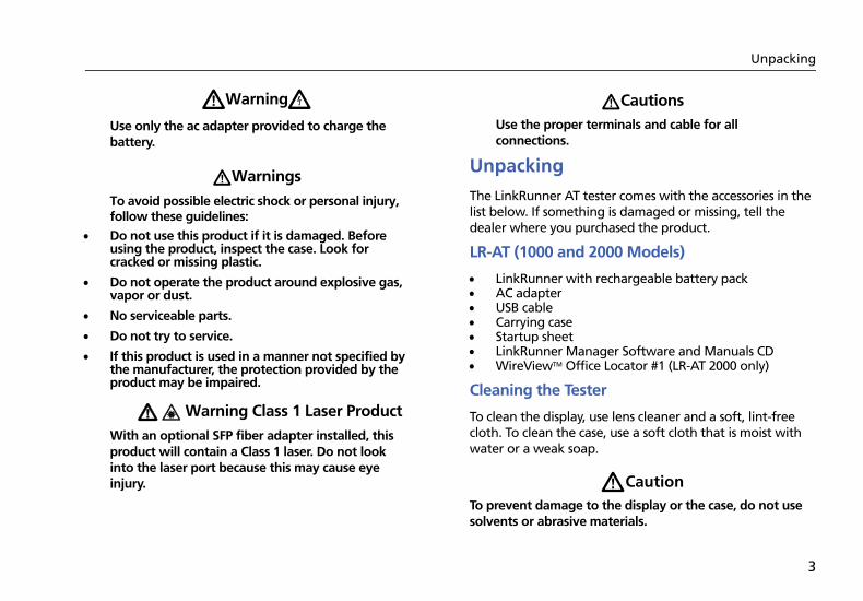
WWarningX
Use only the ac adapter provided to charge the battery.
WWarnings
To avoid possible electric shock or personal injury, follow these guidelines:
Do not use this product if it is damaged. Before using the product, inspect the case. Look for cracked or missing plastic.
Do not operate the product around explosive gas, vapor or dust.
No serviceable parts.
Do not try to service.
If this product is used in a manner not specified by the manufacturer, the protection provided by the product may be impaired.
W * Warning Class 1 Laser Product
With an optional SFP fiber adapter installed, this product will contain a Class 1 laser. Do not look into the laser port because this may cause eye injury.
WCautionsUse the proper terminals and cable for all connections.
Unpacking
The LinkRunner AT tester comes with the accessories in the list below. If something is damaged or missing, tell the dealer where you purchased the product.
LR-AT (1000 and 2000 Models)
LinkRunner with rechargeable battery pack AC adapter USB cable Carrying case Startup sheet LinkRunner Manager Software and Manuals CD WireViewTM Office Locator #1 (LR-AT 2000 only)
Cleaning the Tester
To clean the display, use lens cleaner and a soft, lint-free cloth. To clean the case, use a soft cloth that is moist with water or a weak soap.
WCautionTo prevent damage to the display or the case, do not use solvents or abrasive materials.
LinkRunner AT 1000/2000 Network Auto-TesterUsers Manual
4
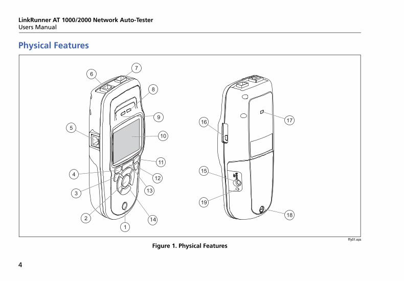
Physical Features
ffy01.eps
Figure 1. Physical Features
67
8
1716
15
19
18
9
10
11
12
13
2
3
4
5
114
Physical Features
5
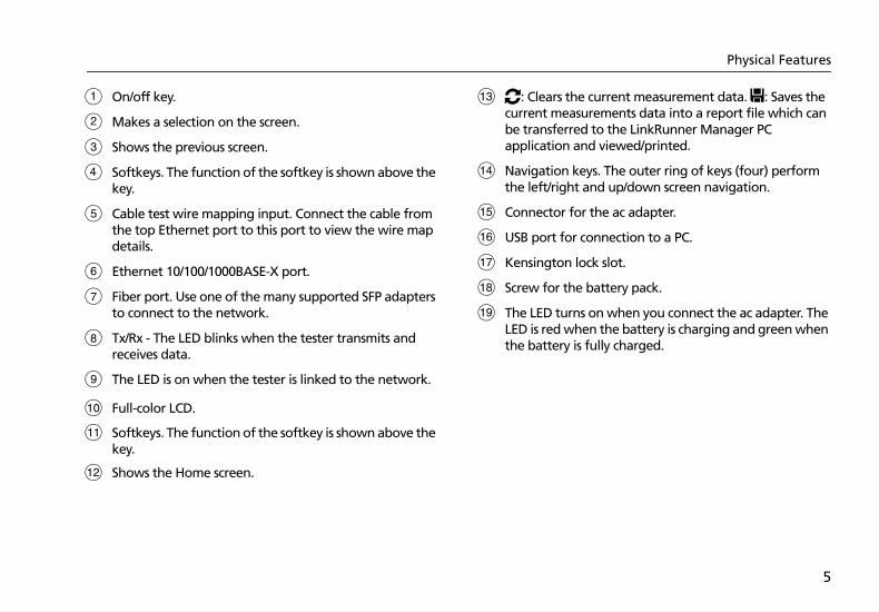
On/off key.
Makes a selection on the screen.
Shows the previous screen.
Softkeys. The function of the softkey is shown above the key.
Cable test wire mapping input. Connect the cable from the top Ethernet port to this port to view the wire map details.
Ethernet 10/100/1000BASE-X port.
Fiber port. Use one of the many supported SFP adapters to connect to the network.
Tx/Rx - The LED blinks when the tester transmits and receives data.
The LED is on when the tester is linked to the network.
Full-color LCD.
Softkeys. The function of the softkey is shown above the key.
Shows the Home screen.
O: Clears the current measurement data. P: Saves the current measurements data into a report file which can be transferred to the LinkRunner Manager PC application and viewed/printed.
Navigation keys. The outer ring of keys (four) perform the left/right and up/down screen navigation.
Connector for the ac adapter.
USB port for connection to a PC.
Kensington lock slot.
Screw for the battery pack.
The LED turns on when you connect the ac adapter. The LED is red when the battery is charging and green when the battery is fully charged.
LinkRunner AT 1000/2000 Network Auto-TesterUsers Manual
6
The Home Screen
G H
A
C
D
B E
F
Iffy15.eps
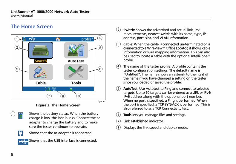
Figure 2. The Home Screen
Shows the battery status. When the battery charge is low, the icon blinks. Connect the ac adapter to charge the battery and to make sure the tester continues to operate.
Shows that the ac adapter is connected.
Shows that the USB interface is connected.
Switch: Shows the advertised and actual link, PoE measurements, nearest switch with its name, type, IP address, port, slot, and VLAN information.
Cable: When the cable is connected un-terminated or is connected to a WireViewTM Office Locator, it shows cable information or wire mapping information. This can also be used to locate a cable with the optional IntelliToneTM probe.
The name of the tester profile. A profile contains the tester configuration settings. The default name is “Untitled”. The name shows an asterisk to the right of the name if you have changed a setting on the tester since you loaded or saved the profile.
AutoTest: Use Autotest to Ping and connect to selected targets. Up to 10 targets can be entered as a URL or IPv4/IPv6 address along with the optional port number. When no port is specified, a Ping is performed. When the port is specified, a TCP SYN/ACK is performed. This is also referred to as a TCP Connectivity test.
Tools lets you manage files and settings.
Link established indicator.
Displays the link speed and duplex mode.
Battery Charging and Life
7
Displays the connection type: PoE , 802.1x , fiber . For 802.1x, a green lock indicates authentication
passed, yellow indicates it is not needed, and a red closed lock indicates it failed authentication.
Battery Charging and Life
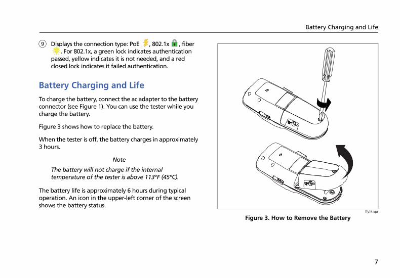
To charge the battery, connect the ac adapter to the battery connector (see Figure 1). You can use the tester while you charge the battery.
Figure 3 shows how to replace the battery.
When the tester is off, the battery charges in approximately 3 hours.
Note
The battery will not charge if the internal temperature of the tester is above 113ºF (45ºC).
The battery life is approximately 6 hours during typical operation. An icon in the upper-left corner of the screen shows the battery status.
ffy14.eps
Figure 3. How to Remove the Battery
LinkRunner AT 1000/2000 Network Auto-TesterUsers Manual
8
Common Questions LR-AT Can Solve
First connect an RJ-45 or fiber cable (2000 model only) from the network hub or wall plate to the LinkRunner AT RJ-45 LAN or fiber port. Check the following list of questions and associated answers to see how LinkRunner AT can help you get the job done.
Common Questions
Q > Is this a good RJ45 Ethernet cable?A > Use Cable testing and the built in wiremap for patch cables, or an external WireviewTM Office Locator.
Q > Am I receiving a good fiber signal?A > Connect to your network via a SFP adapter and validate the signal strength and link in the Switch screen.
Q >Where does this RJ45 cable go?A >Use the Cable test toner function, Switch > Flash Port function, or Switch discovery protocol.
Q > Is this cable hooked up to anything?A > Select Switch to identify an open cable, an active link, an un-powered network device or telephone voltage.
Q > Does this RJ45 drop support PoE?A > Use Tools to specify the desired PoE power class and use Switch or AutoTest to verify the power under load up to 25.5W (802.3at).
Q > What speed/duplex is this device configured for?A > Use Switch to check the advertised and actual speed/duplex. Additionally, use Tools to tests for manual (non-Auto Negotiated) speed/duplex.
Q > Can I see traffic from this connection?A > Observe the utilization LED blinking to see network traffic.
Common Questions LR-AT Can Solve
9
Q> Can I connect in a MAC access control environment?A> Use Tools > VLAN/MAC to specify a user defined MAC address.
Q > Do I have network connectivity?A > Select AutoTest to validate key network services (DHCP, DNS, Router).
Q > Can I get an IPv4 DHCP address?A > Select AutoTest. Select DHCP (or enter a static IP address) in the Tools > IP Configuration menu.
Q> Can I get an IPv6 address?A > Enable IPv6 in Tools > IP Configuration. Use AutoTest to observer the acquired IPv6 link-local and global address.
Q > Can I PING?A > Select AutoTest. Configure an address to Ping under Tools > AutoTest Configuration.
Q> Can I verify application connectivity?A > Select AutoTest. Configure an address and application port (e.g. port 80 for web/HTTP) under Tools > AutoTest Configuration.
Q > Can I use it for throughput testing?A> Use the Reflector tool (setup under Tools - only available on LR-AT 2000 model).
Q > Can I connect to an 802.1X port?A > Use the Tools > Connect Configuration screen to enable 802.1X. Also, use the LinkRunner Manager PC application (select Tools > General Information to enable 802.1X and set up security).
LinkRunner AT 1000/2000 Network Auto-TesterUsers Manual
10
Saving a Report
You can save the current measurement data the tester has collected into a report that can be viewed and printed through the LinkRunner Manager PC application. This information includes:
AutoTest results
Switch results
Cable test results
Note
The LR-AT 1000 model can save up to 10 reports. The LR-AT 2000 model can save up to 50 reports.
To save the measurement data collected on the tester:
1 Press P. The tester shows a default filename at the bottom of the screen.
To save the data with the filename shown, press Save. The tester saves the data into a report file.
To overwrite a report that is saved on the tester, highlight the report, press L, press Save, then press OK.
To change the filename, press Edit.
Note
Report names can have a maximum of 12 characters. The extension LRS is appended when the file is saved to your PC through the LinkRunner Manager PC application.
To delete characters in the filename, press Backspace.
To add characters to the filename, use to highlight a character, then press L.
To move the cursor in the filename, highlight the filename, then press .
To save the report with the edited filename, press Save, then press Save.
To view the report, open it in LinkRunner Manager. Refer to the LinkRunner Manager help for instructions.
Set Up the Tester
11
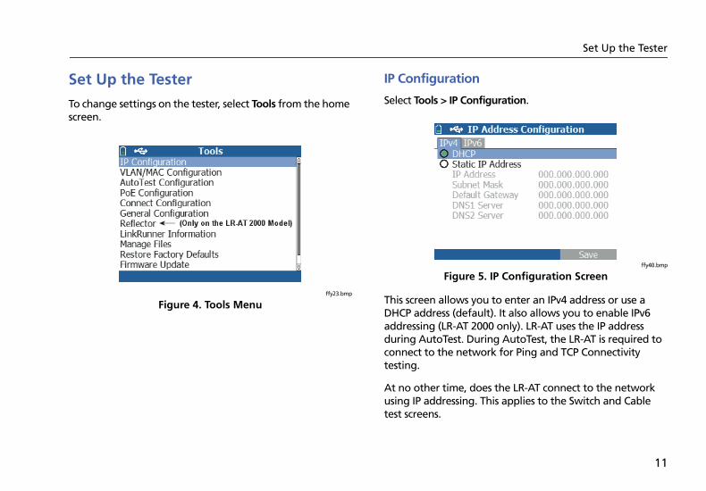
Set Up the Tester
To change settings on the tester, select Tools from the home screen.
ffy23.bmp
Figure 4. Tools Menu
IP Configuration
Select Tools > IP Configuration.
ffy40.bmp
Figure 5. IP Configuration Screen
This screen allows you to enter an IPv4 address or use a DHCP address (default). It also allows you to enable IPv6 addressing (LR-AT 2000 only). LR-AT uses the IP address during AutoTest. During AutoTest, the LR-AT is required to connect to the network for Ping and TCP Connectivity testing.
At no other time, does the LR-AT connect to the network using IP addressing. This applies to the Switch and Cable test screens.
LinkRunner AT 1000/2000 Network Auto-TesterUsers Manual
12
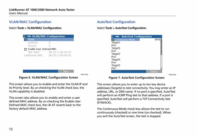
VLAN/MAC Configuration
Select Tools > VLAN/MAC Configuration.
ffy41.bmp
Figure 6. VLAN/MAC Configuration Screen
This screen allows you to enable and enter the VLAN IP and its Priority level. By un-checking the VLAN check box, the VLAN capability is disabled.
This screen also allows you to enable and enter a user defined MAC address. By un-checking the Enable User Defined MAC check box, the LR-AT reverts back to the factory default MAC address.
AutoTest Configuration
Select Tools > AutoTest Configuration.
ffy42.bmp
Figure 7. AutoTest Configuration Screen
This screen allows you to enter up to ten key device addresses (Targets) to test connectivity. You may enter an IP address, URL, or DNS name. If no port is specified, AutoTest will perform an ICMP Ping test to that address. If a port is specified, AutoTest will perform a TCP Connectivity test (SYN/ACK).
The Continuous Mode check box allows the test to run continuously (checked) or one time (un-checked). When you exit the AutoTest screen, the test is stopped.
Set Up the Tester
13
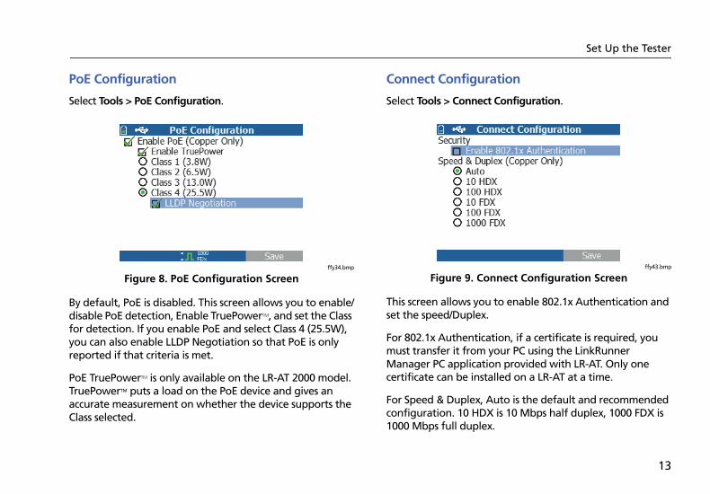
PoE Configuration
Select Tools > PoE Configuration.
ffy34.bmp
Figure 8. PoE Configuration Screen
By default, PoE is disabled. This screen allows you to enable/disable PoE detection, Enable TruePowerTM, and set the Class for detection. If you enable PoE and select Class 4 (25.5W), you can also enable LLDP Negotiation so that PoE is only reported if that criteria is met.
PoE TruePowerTM is only available on the LR-AT 2000 model. TruePowerTM puts a load on the PoE device and gives an accurate measurement on whether the device supports the Class selected.
Connect Configuration
Select Tools > Connect Configuration.
ffy43.bmp
Figure 9. Connect Configuration Screen
This screen allows you to enable 802.1x Authentication and set the speed/Duplex.
For 802.1x Authentication, if a certificate is required, you must transfer it from your PC using the LinkRunner Manager PC application provided with LR-AT. Only one certificate can be installed on a LR-AT at a time.
For Speed & Duplex, Auto is the default and recommended configuration. 10 HDX is 10 Mbps half duplex, 1000 FDX is 1000 Mbps full duplex.
LinkRunner AT 1000/2000 Network Auto-TesterUsers Manual
14
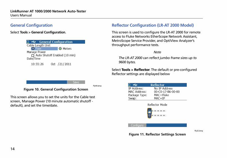
General Configuration
Select Tools > General Configuration.
ffy44.bmp
Figure 10. General Configuration Screen
This screen allows you to set the units for the Cable test screen, Manage Power (10 minute automatic shutoff - default), and set the time/date.
Reflector Configuration (LR-AT 2000 Model)
This screen is used to configure the LR-AT 2000 for remote access to Fluke Networks EtherScope Network Assistant, MetroScope Service Provider, and OptiView Analyzer’s throughput performance tests.
Note
The LR-AT 2000 can reflect jumbo frame sizes up to 9600 bytes.
Select Tools > Reflector. The default or pre-configured Reflector settings are displayed below
ffy32.bmp
Figure 11. Reflector Settings Screen
Set Up the Tester
15
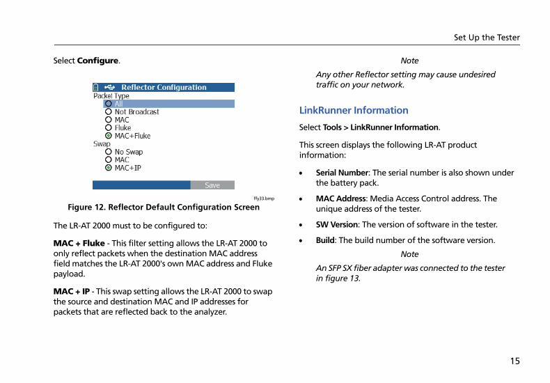
Select Configure.
ffy33.bmp
Figure 12. Reflector Default Configuration Screen
The LR-AT 2000 must to be configured to:
MAC + Fluke - This filter setting allows the LR-AT 2000 to only reflect packets when the destination MAC address field matches the LR-AT 2000's own MAC address and Fluke payload.
MAC + IP - This swap setting allows the LR-AT 2000 to swap the source and destination MAC and IP addresses for packets that are reflected back to the analyzer.
Note
Any other Reflector setting may cause undesired traffic on your network.
LinkRunner Information
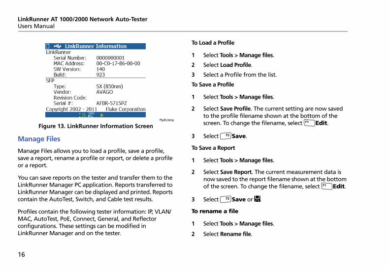
Select Tools > LinkRunner Information.
This screen displays the following LR-AT product information:
Serial Number: The serial number is also shown under the battery pack.
MAC Address: Media Access Control address. The unique address of the tester.
SW Version: The version of software in the tester.
Build: The build number of the software version.
Note
An SFP SX fiber adapter was connected to the tester in figure 13.
LinkRunner AT 1000/2000 Network Auto-TesterUsers Manual
16
ffy45.bmp
Figure 13. LinkRunner Information Screen
Manage Files
Manage Files allows you to load a profile, save a profile, save a report, rename a profile or report, or delete a profile or a report.
You can save reports on the tester and transfer them to the LinkRunner Manager PC application. Reports transferred to LinkRunner Manager can be displayed and printed. Reports contain the AutoTest, Switch, and Cable test results.
Profiles contain the following tester information: IP, VLAN/MAC, AutoTest, PoE, Connect, General, and Reflector configurations. These settings can be modified in LinkRunner Manager and on the tester.
To Load a Profile
1 Select Tools > Manage files.
2 Select Load Profile.
3 Select a Profile from the list.
To Save a Profile
1 Select Tools > Manage files.
2 Select Save Profile. The current setting are now saved to the profile filename shown at the bottom of the screen. To change the filename, select Edit.
3 Select Save.
To Save a Report
1 Select Tools > Manage files.
2 Select Save Report. The current measurement data is now saved to the report filename shown at the bottom of the screen. To change the filename, select Edit.
3 Select Save or P.
To rename a file
1 Select Tools > Manage files.
2 Select Rename file.
Set Up the Tester
17
3 Highlight either the Report or Profile folder.
4 Highlight the file, then press L.
5 To edit the filename, press Edit.
To delete characters in the filename, press Delete.
To add characters to the filename, use to highlight a character, then press L.
To move the cursor in the filename, highlight the filename, then press .
6 To rename the file with the name you made, press Save, then press Rename.
To delete a file
1 Select Tools > Manage files.
2 Select Delete file.
3 Highlight either the Report or Profile folder.
4 Highlight a file, then press L.
5 Press Delete.
Restore Factory Defaults
Restores any configuration changes to the following LinkRunner AT factory defaults.
IP Configuration:IPv4: DHCPIPv6: Disabled
VLAN/MAC Configuration:VLAN: DisabledVLAN ID: 0Priority: 0User Defined MAC: DisabledMAC Address: Linkrunner MAC address
AutoTest Configuration:Continuous Mode: OnTarget: none
PoE Configuration:Enable PoE: DisabledClass: Class 1
Connect Configuration:802.1x: DisabledSpeed/Duplex: Auto
LinkRunner AT 1000/2000 Network Auto-TesterUsers Manual
18
General Configuration:Cable Length Unit, MetersAuto Shutoff, Enabled
Set Language:English
When you Select Restore Factory Defaults, you will be prompted with a two popup. Select OK, then press L.
The restore will be completed and the tester will turn off.
Firmware Update
1 Download the LinkRunner firmware update file from the Fluke Networks website, or contact Fluke Networks to get the update by other means. Save the file to your hard disk.
2 Get the latest version of LinkRunner Manager from the Fluke Networks website.
3 Start LinkRunner Manager on your PC.
4 Turn on the tester.
5 Select Tools > Firmware Update > select Update.
6 Use the USB cable supplied with the tester to connect the tester to the PC.
7 In LinkRunner Manager, select LinkRunner > Update Software.
8 Click Select, find and select the update file (.zip extension), then click Select.
9 Click Update.
10 When the transfer is completed, disconnect the USB cable from the tester.
11 The screen on the tester goes blank while it installs the update file. When the update is completed, restart the tester.
WCaution
Do not disconnect the LinkRunner from the PC or remove the battery during the update.
Using AutoTest, Switch, and Cable Test
19
Transfer Saved Profiles to/from LinkRunner Manager
Use LinkRunner Manager to view and configure the profiles that are saved on the tester. To transfer profiles from the tester to LinkRunner Manager:
1 Install the latest version of LinkRunner Manager software on your PC. Start the software.
2 Turn on the tester.
3 Use the USB cable supplied with the tester to connect the tester to the PC.
4 To see the profiles that are on the tester, select Tools > Profile Manager from the LinkRunner Manager tool bar. Profile names display under the LinkRunner Profile Files pane.
5 Highlight a profile in this pane and select Transfer from LinkRunner.
6 When you are done editing the profile, highlight it and select Transfer to LinkRunner.
Set Language
To change the language displayed in all screens
1 Select Tools > Set Language.
2 Highlight a language and press Save.
Using AutoTest, Switch, and Cable Test
Using AutoTest
AutoTest can test up to ten targets. These targets can be local or off-net targets (devices). You can enter the IP address or a DNS name. If you specify a target address without specifying a port number, AutoTest will perform an ICMP Ping to the target address. If you specify a port number, AutoTest will perform a TCP Connectivity test (SYN/ACK). See figures 14 and 15.
Select Tools > AutoTest Configuration and enter the target address(s). Entering a port number is optional. AutoTest will attempt to Ping/Connect to the target device three times. If Continuous is selected, the test will run until you exit the AutoTest screen.
LinkRunner AT 1000/2000 Network Auto-TesterUsers Manual
20
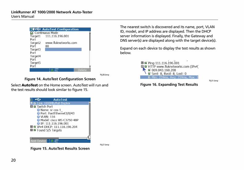
ffy28.bmp
Figure 14. AutoTest Configuration Screen
Select AutoTest on the Home screen. AutoTest will run and the test results should look similar to figure 15.
ffy27.bmp
Figure 15. AutoTest Results Screen
The nearest switch is discovered and its name, port, VLAN ID, model, and IP address are displayed. Then the DHCP server information is displayed. Finally, the Gateway and DNS server(s) are displayed along with the target device(s).
Expand on each device to display the test results as shown below.
ffy31.bmp
Figure 16. Expanding Test Results
Using AutoTest, Switch, and Cable Test
21
Using the Nearest Switch Test
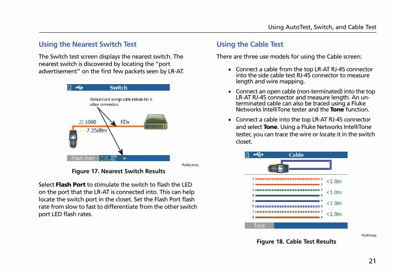
The Switch test screen displays the nearest switch. The nearest switch is discovered by locating the “port advertisement” on the first few packets seen by LR-AT.
ffy46a.bmp
Figure 17. Nearest Switch Results
Select Flash Port to stimulate the switch to flash the LED on the port that the LR-AT is connected into. This can help locate the switch port in the closet. Set the Flash Port flash rate from slow to fast to differentiate from the other switch port LED flash rates.
Using the Cable Test
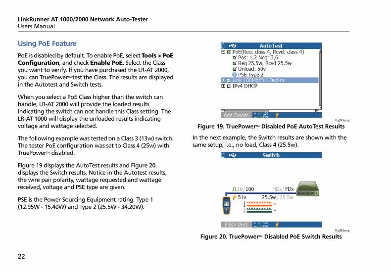
There are three use models for using the Cable screen:
Connect a cable from the top LR-AT RJ-45 connector into the side cable test RJ-45 connector to measure length and wire mapping.
Connect an open cable (non-terminated) into the top LR-AT RJ-45 connector and measure length. An un-terminated cable can also be traced using a Fluke Networks IntelliTone tester and the Tone function.
Connect a cable into the top LR-AT RJ-45 connector and select Tone. Using a Fluke Networks IntelliTone tester, you can trace the wire or locate it in the switch closet.
ffy30.bmp
Figure 18. Cable Test Results
LinkRunner AT 1000/2000 Network Auto-TesterUsers Manual
22
Using PoE Feature
PoE is disabled by default. To enable PoE, select Tools > PoE Configuration, and check Enable PoE. Select the Class you want to verify. If you have purchased the LR-AT 2000, you can TruePowerTM test the Class. The results are displayed in the Autotest and Switch tests.
When you select a PoE Class higher than the switch can handle, LR-AT 2000 will provide the loaded results indicating the switch can not handle this Class setting. The LR-AT 1000 will display the unloaded results indicating voltage and wattage selected.
The following example was tested on a Class 3 (13w) switch. The tester PoE configuration was set to Class 4 (25w) with TruePowerTM disabled.
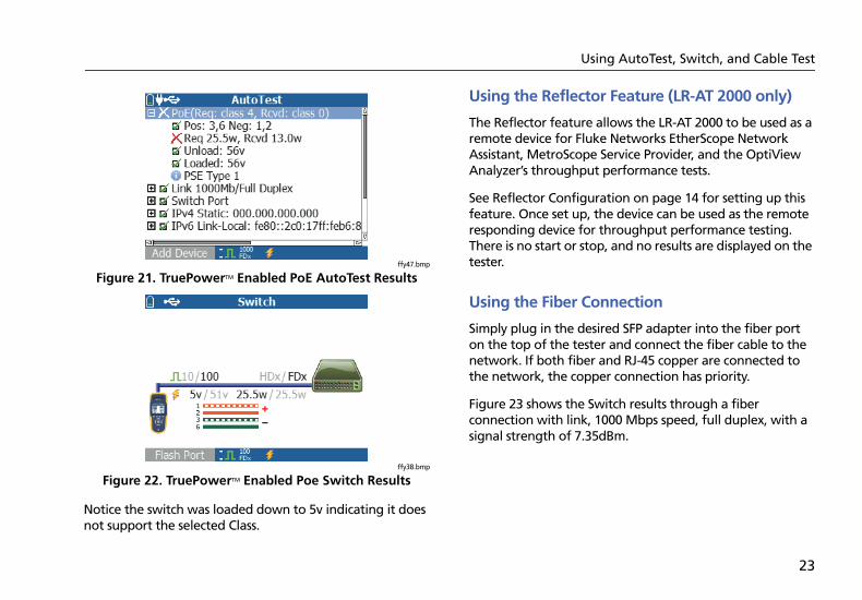
Figure 19 displays the AutoTest results and Figure 20 displays the Switch results. Notice in the Autotest results, the wire pair polarity, wattage requested and wattage received, voltage and PSE type are given.
PSE is the Power Sourcing Equipment rating, Type 1 (12.95W - 15.40W) and Type 2 (25.5W - 34.20W).
ffy37.bmp
Figure 19. TruePowerTM Disabled PoE AutoTest Results
In the next example, the Switch results are shown with the same setup, i.e., no load, Class 4 (25.5w).
ffy39.bmp
Figure 20. TruePowerTM Disabled PoE Switch Results
Using AutoTest, Switch, and Cable Test
23
ffy47.bmp
Figure 21. TruePowerTM Enabled PoE AutoTest Results
ffy38.bmp
Figure 22. TruePowerTM Enabled Poe Switch Results
Notice the switch was loaded down to 5v indicating it does not support the selected Class.
Using the Reflector Feature (LR-AT 2000 only)
The Reflector feature allows the LR-AT 2000 to be used as a remote device for Fluke Networks EtherScope Network Assistant, MetroScope Service Provider, and the OptiView Analyzer’s throughput performance tests.
See Reflector Configuration on page 14 for setting up this feature. Once set up, the device can be used as the remote responding device for throughput performance testing. There is no start or stop, and no results are displayed on the tester.
Using the Fiber Connection
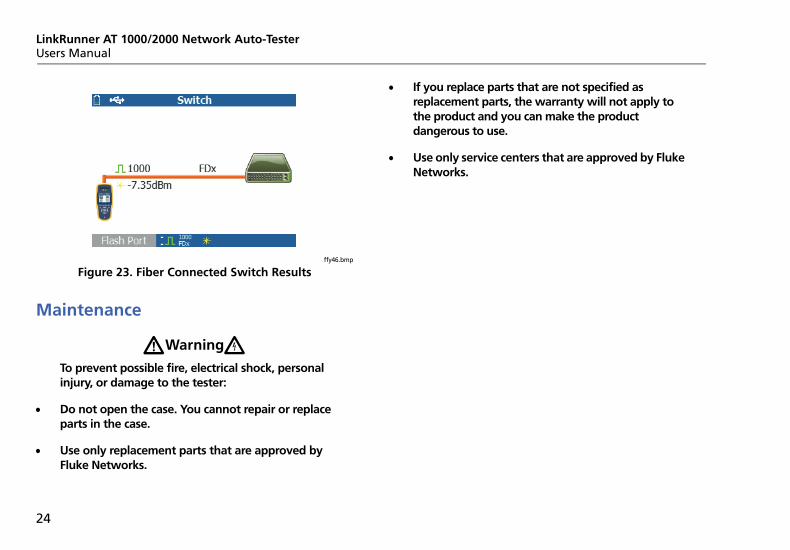
Simply plug in the desired SFP adapter into the fiber port on the top of the tester and connect the fiber cable to the network. If both fiber and RJ-45 copper are connected to the network, the copper connection has priority.
Figure 23 shows the Switch results through a fiber connection with link, 1000 Mbps speed, full duplex, with a signal strength of 7.35dBm.
LinkRunner AT 1000/2000 Network Auto-TesterUsers Manual
24
ffy46.bmp
Figure 23. Fiber Connected Switch Results
Maintenance
WWarningXTo prevent possible fire, electrical shock, personal injury, or damage to the tester:
Do not open the case. You cannot repair or replace parts in the case.
Use only replacement parts that are approved by Fluke Networks.
If you replace parts that are not specified as replacement parts, the warranty will not apply to the product and you can make the product dangerous to use.
Use only service centers that are approved by Fluke Networks.
Options and Accessories
25
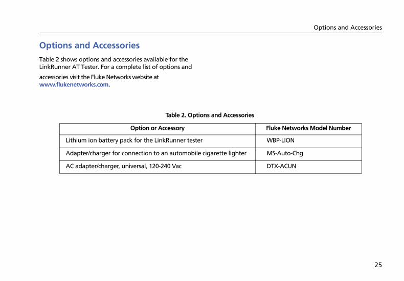
Options and Accessories
Table 2 shows options and accessories available for the LinkRunner AT Tester. For a complete list of options and
accessories visit the Fluke Networks website at www.flukenetworks.com.
Table 2. Options and Accessories
Option or Accessory Fluke Networks Model Number
Lithium ion battery pack for the LinkRunner tester WBP-LION
Adapter/charger for connection to an automobile cigarette lighter MS-Auto-Chg
AC adapter/charger, universal, 120-240 Vac DTX-ACUN
LinkRunner AT 1000/2000 Network Auto-TesterUsers Manual
26
Specifications
Environmental Specifications
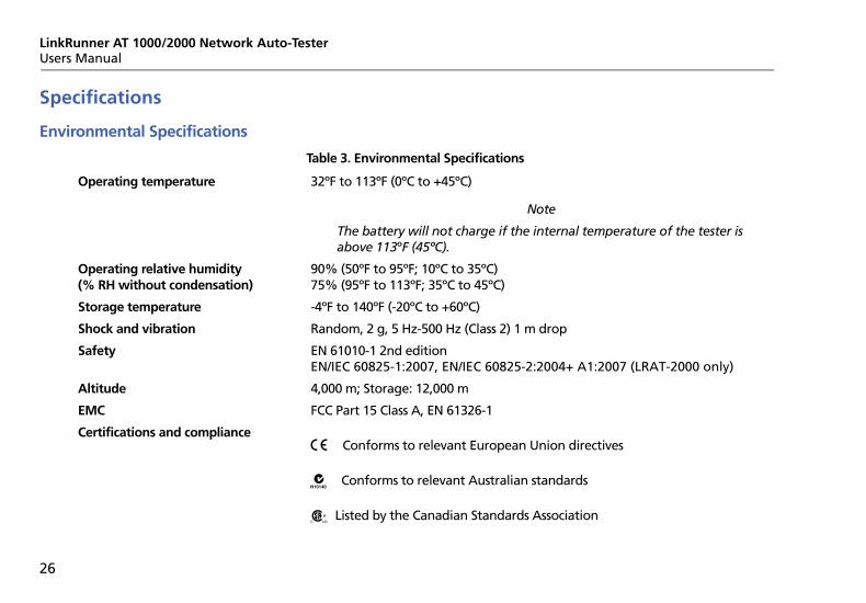
Table 3. Environmental Specifications
32ºF to 113ºF (0ºC to +45ºC)
Note
The battery will not charge if the internal temperature of the tester is above 113ºF (45ºC).
90% (50ºF to 95ºF; 10ºC to 35ºC)75% (95ºF to 113ºF; 35ºC to 45ºC)
-4ºF to 140ºF (-20ºC to +60ºC)
Random, 2 g, 5 Hz-500 Hz (Class 2) 1 m drop
EN 61010-1 2nd editionEN/IEC 60825-1:2007, EN/IEC 60825-2:2004+ A1:2007 (LRAT-2000 only)
4,000 m; Storage: 12,000 m
FCC Part 15 Class A, EN 61326-1
Operating temperature
Operating relative humidity(% RH without condensation)
Storage temperature
Shock and vibration
Safety
Altitude
EMC
Certifications and compliancePConforms to relevant European Union directives
Conforms to relevant Australian standards
)Listed by the Canadian Standards Association

Specifications
27
General Specifications
Table 4. General Specifications
10BASE-T, 100BASE-TX, 1000BASE-T (IEEE-802.3) and Poe (IEEE 802.3at)
Pair lengths, opens, shorts, splits, crossed, straight through, and cable ID
IntelliTone digital tone: [500 KHz]; analog tones: [400Hz, 1KHz]
3.5 in x 7.8 in x 1.9 in (8.9 cm x 19.8 cm x 4.8 cm)
18 oz (0.5 kg)
Removable, rechargeable lithium-ion battery pack (18.5 Watt-hrs)
Typical operating life is 6 hours. Typical charge time is 3 hours.
AC input 90-264 Vac 48-62 Hz input power DC output 15 Vdc at 1.2 amps
2.8 in color LCD (320 x 240 pixels)
12-key elastomeric
2 LEDs (transmit and link Indicators)
USB 5-pin mini-B
Media Access
Cable Test
Tone Generator
Ports RJ45 copper port 1000BASE-X fiber adapter port (2000 only)
Dimensions
Weight
Battery
Battery life
External AC adapter/charger
Display
Keypad
LEDs
Host interface
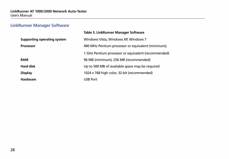
Table 5. LinkRunner Manager Software
Windows Vista, Windows XP, Windows 7
400 MHz Pentium processor or equivalent (minimum);
1 GHz Pentium processor or equivalent (recommended)
96 MB (minimum); 256 MB (recommended)
Up to 500 MB of available space may be required
1024 x 768 high color, 32-bit (recommended)
USB Port
LinkRunner AT 1000/2000 Network Auto-TesterUsers Manual
28
LinkRunner Manager Software
Supporting operating system
Processor
RAM
Hard disk
Display
Hardware