Linking Cancer Rates & Chemical Release in Florida GIS 5100 Trisha Holtzclaw Javier Leung.
Environmental Modelling & Software 17 (2002) 413–425www.elsevier.com/locate/envsoft
Linking GIS and water resources management models:an object-oriented method
Daene C. McKinneya, Ximing Caib,∗
a Department of Civil Engineering, University of Texas, Austin, TX 78212, USAb International Food Policy Research Institute (IFPRI), 2033 K St. Washington, DC 20006, USA
Received 4 June 2001; received in revised form 3 September 2001; accepted 21 November 2001
Abstract
Many challenges are associated with the integration of geographic information systems (GISs) with models in specific applications.One of them is adapting models to the environment of GISs. Unique aspects of water resource management problems require aspecial approach to development of GIS data structures. Expanded development of GIS applications for handling water resourcesmanagement analysis can be assisted by use of an object oriented approach. In this paper, we model a river basin water allocationproblem as a collection of spatial and thematic objects. A conceptual GIS data model is formulated to integrate the physical andlogical components of the modeling problem into an operational framework, based on which, extended GIS functions are developedto implement a tight linkage between the GIS and the water resources management model. Through the object-oriented approach,data, models and users interfaces are integrated in the GIS environment, creating great flexibility for modeling and analysis. Theconcept and methodology described in this paper is also applicable to connecting GIS with models in other fields that have a spatialdimension and hence to which GIS can provide a powerful additional component of the modeler’s tool kit. 2002 Elsevier ScienceLtd. All rights reserved.
Keywords: GIS; Object-oriented method; Water resources modelling
1. Introduction
1.1. GIS and analytical models
GIS is a general-purpose technology for handling geo-graphic data in digital form. Its abilities include: prepro-cessing data into a form suitable for analysis, supportingspatial analysis and modeling directly, and postpro-cessing results (Goodchild, 1993). GISs offer a spatialrepresentation of water resource systems. A GIS canbring spatial dimensions into the traditional waterresource data base, and it has the ability to present anintegrated view of the world. This is accomplished bycombining various social, economic and environmentalfactors related to spatial entities of a water resourcesproblem and making them available for use in a
∗ Corresponding author.E-mail addresses: [email protected] (D.C. McKinney); x.cai@
cgiar.org (X. Cai).
1364-8152/02/$ - see front matter 2002 Elsevier Science Ltd. All rights reserved.PII: S1364-8152 (02)00015-4
decision-making process (Csillag, 1996). In particular,the visual display capacity of GISs compliments the userinterface of water resources models, allowing the userto take more complete control of data input and manipu-lation. Sophisticated graphical user interfaces can pro-vide user-defined triggers, which allow the user to dictatehow features will respond to environmental changes, andto construct rules to control the modeling process(Crosbie, 1996).
For water resources problem solving, both a spatialrepresentation of the system and an insight into waterresource problems are necessary. GIS can represent thegeo-referenced characteristics and spatial relationshipsof systems, but predictive and related analyticalcapacities are more useful and necessary for solvingcomplex water resources planning and managementproblems (Walsh, 1992). In order to take advantage ofGISs to improve water resources planning and manage-ment, it is an attractive idea to link GISs with traditionalmathematical models. Densham and Goodchild (1989)presented an approach to develop spatial decision sup-
414 D.C. McKinney, X. Cai / Environmental Modelling & Software 17 (2002) 413–425
port systems (SDSS) to integrate spatial data and mode-ling capacity into an operational framework by linkinga DSS and a GIS. Walsh (1992) and Leipnik et al. (1993)provided a comprehensive discussion on the potential forextending GIS applications in water resources. Otherrelated studies include Nyerges (1993), Watkins andMcKinney (1995), Fedra (1996), Keller and Strapp(1996), McKinney and Tsai (1996), Watkins et al.(1996), and Sample et al. (2001). In particular, for gen-eral issues in GIS-based modeling, Miles and Ho (2001)discussed the limitations, alternatives, and context ofGIS as a burgeoning tool proliferating in civil engineer-ing. The authors summarized the benefits of using GISas a supplement to engineering modeling, and promotedawareness of the issues related to GIS-based modeling.
There are several strategies for coupling an environ-mental model to a GIS. These can range from a looseto a tight coupling. A loose coupling is where data aretransferred between models and GIS, and each has separ-ate database management capabilities and systems. Atight coupling is where data management in the GIS andmodel are integrated and they share the same database(Fedra and Kubat, 1996; Djokic and Maidment, 1993).The tightest coupling is an embedded system, in whichmodeling and data are embedded in a single manipu-lation framework (Densham and Goodchild 1989; Cros-bie, 1996; McKinney and Tsai, 1996; Reitsma 1996;Fedra and Jamieson, 1996).
1.2. Object-oriented methods to link GISs and models
Object-oriented methods are promising for tight coup-ling of GISs and environmental models (Ye et al., 1996;Reitsma et al., 1994; Fedra, 1996; Crosbie, 1996). Theidea behind these methods is that the world can be per-ceived as consisting of objects that interact in variousways (Crosbie, 1996). Object-oriented representations ofthe world consist of spatial objects and thematic objects.Spatial objects represent real world entities, with bothgeographical and physical, environmental and socio-economic attributes (see Table 1 for spatial objects inriver basin systems). Thematic objects represent methodsand topics relevant to the spatial objects. Methods arefunctions for describing or exploring relationshipsbetween spatial objects, for example, flow balance in areservoir. Topics, which are identified through user inter-actions, are tasks to be completed or objectives to bereached, for example, water supply target of a reservoir.Thus, models and GIS functions can be viewed asmethods applied to topics. The integration of models andGIS functions then becomes a pragmatic question ofchoosing a method to perform a task on the selectedobjects (Fedra, 1996).
Many applications of the object-oriented method havebeen reported in the water resources literature. Reitsmaet al. (1994) presented an object-oriented method applied
in the Power and Reservoir System Model (PRSYM,CADSWES, 1993). Physical entities in a river basinwere defined as objects, and each object contained all ofthe information necessary to determine its state and tocommunicate with other objects. User’s functions, whichwere defined as external objects, allow users to directlyaccess the objects. PRSYM provides flexible and rapidconstruction of modifiable river-simulation models basedon a set of primitive water and information objects.
Fedra and Jamieson (1996) described an object ori-ented information and decision support system for riverbasin management, called WaterWare. Three classes ofobjects were defined in WaterWare: RiverBasinObjects,representing real world entities; NetworkObjects, rep-resenting abstraction of the real world entities; and Scen-arioObjects, representing model oriented scenarios ofNetworkObjects that are partially derived from, andlinked to, the RiverBasinObjects. These objects and vari-ous analysis functions can be manipulated within a com-mon interface designed in a multi-media framework, andinformation for decision support is therefore translatedthrough the interface.
Tisdale (1996) applied an object-oriented analysis tosouth Florida hydrologic systems, and showed that thismethodology could organize system information well.Conceptual models were developed to identify systemcomponents and their attributes, and to simulate inter-relations between objects. These models were combinedto characterize the overall structure, behavior, and func-tionality of hydrologic systems.
A ‘map-centric’ and object-oriented system wasdeveloped by Ye et al. (1996) which provided map-based surface/subsurface water flow simulation mode-ling capability. This system was applied to simulate sur-face and subsurface flow in the Niger River Basin ofWest Africa.
Many challenges are associated with the integrationof GISs with models in specific applications. One ofthem is adapting models to the environment of GISs.Unique aspects of water resource management problemsrequire a special approach to GIS data structure andexpanded development of GIS applications for handlingwater resources management analysis in a GIS. In thispaper, we apply an object-oriented method develop atight link between a GIS and a water resources manage-ment model for optimal water allocation in river basins.Research issues addressed in this paper include: (1) howto represent the data and functions of a water resourcesmanagement model as spatial and thematic character-istics in a GIS; (2) how to integrate problem definition,data manipulation and analytical functions in a GISenvironment; and (3) how to implement the model for-mulation and result analysis taking advantage of a GIS’sspatial capabilities. These issues are addressed in thispaper by: (1) formulating a conceptual model that inte-grates data, model and user interactions in a GIS
415D.C. McKinney, X. Cai / Environmental Modelling & Software 17 (2002) 413–425
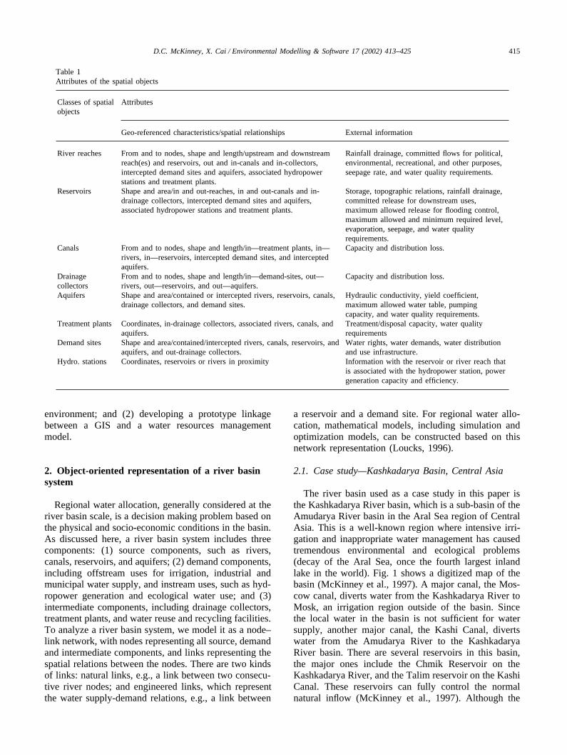
Table 1Attributes of the spatial objects
Classes of spatial Attributesobjects
Geo-referenced characteristics/spatial relationships External information
River reaches From and to nodes, shape and length/upstream and downstream Rainfall drainage, committed flows for political,reach(es) and reservoirs, out and in-canals and in-collectors, environmental, recreational, and other purposes,intercepted demand sites and aquifers, associated hydropower seepage rate, and water quality requirements.stations and treatment plants.
Reservoirs Shape and area/in and out-reaches, in and out-canals and in- Storage, topographic relations, rainfall drainage,drainage collectors, intercepted demand sites and aquifers, committed release for downstream uses,associated hydropower stations and treatment plants. maximum allowed release for flooding control,
maximum allowed and minimum required level,evaporation, seepage, and water qualityrequirements.
Canals From and to nodes, shape and length/in—treatment plants, in— Capacity and distribution loss.rivers, in—reservoirs, intercepted demand sites, and interceptedaquifers.
Drainage From and to nodes, shape and length/in—demand-sites, out— Capacity and distribution loss.collectors rivers, out—reservoirs, and out—aquifers.Aquifers Shape and area/contained or intercepted rivers, reservoirs, canals, Hydraulic conductivity, yield coefficient,
drainage collectors, and demand sites. maximum allowed water table, pumpingcapacity, and water quality requirements.
Treatment plants Coordinates, in-drainage collectors, associated rivers, canals, and Treatment/disposal capacity, water qualityaquifers. requirements
Demand sites Shape and area/contained/intercepted rivers, canals, reservoirs, and Water rights, water demands, water distributionaquifers, and out-drainage collectors. and use infrastructure.
Hydro. stations Coordinates, reservoirs or rivers in proximity Information with the reservoir or river reach thatis associated with the hydropower station, powergeneration capacity and efficiency.
environment; and (2) developing a prototype linkagebetween a GIS and a water resources managementmodel.
2. Object-oriented representation of a river basinsystem
Regional water allocation, generally considered at theriver basin scale, is a decision making problem based onthe physical and socio-economic conditions in the basin.As discussed here, a river basin system includes threecomponents: (1) source components, such as rivers,canals, reservoirs, and aquifers; (2) demand components,including offstream uses for irrigation, industrial andmunicipal water supply, and instream uses, such as hyd-ropower generation and ecological water use; and (3)intermediate components, including drainage collectors,treatment plants, and water reuse and recycling facilities.To analyze a river basin system, we model it as a node–link network, with nodes representing all source, demandand intermediate components, and links representing thespatial relations between the nodes. There are two kindsof links: natural links, e.g., a link between two consecu-tive river nodes; and engineered links, which representthe water supply-demand relations, e.g., a link between
a reservoir and a demand site. For regional water allo-cation, mathematical models, including simulation andoptimization models, can be constructed based on thisnetwork representation (Loucks, 1996).
2.1. Case study—Kashkadarya Basin, Central Asia
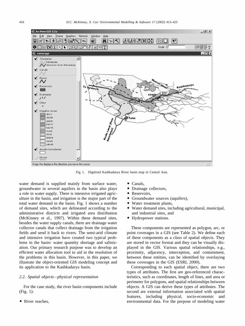
The river basin used as a case study in this paper isthe Kashkadarya River basin, which is a sub-basin of theAmudarya River basin in the Aral Sea region of CentralAsia. This is a well-known region where intensive irri-gation and inappropriate water management has causedtremendous environmental and ecological problems(decay of the Aral Sea, once the fourth largest inlandlake in the world). Fig. 1 shows a digitized map of thebasin (McKinney et al., 1997). A major canal, the Mos-cow canal, diverts water from the Kashkadarya River toMosk, an irrigation region outside of the basin. Sincethe local water in the basin is not sufficient for watersupply, another major canal, the Kashi Canal, divertswater from the Amudarya River to the KashkadaryaRiver basin. There are several reservoirs in this basin,the major ones include the Chmik Reservoir on theKashkadarya River, and the Talim reservoir on the KashiCanal. These reservoirs can fully control the normalnatural inflow (McKinney et al., 1997). Although the
416 D.C. McKinney, X. Cai / Environmental Modelling & Software 17 (2002) 413–425
Fig. 1. Digitized Kashkadarya River basin map in Central Asia.
water demand is supplied mainly from surface water,groundwater in several aquifers in the basin also playsa role in water supply. There is intensive irrigated agric-ulture in the basin, and irrigation is the major part of thetotal water demand in the basin. Fig. 1 shows a numberof demand sites, which are delineated according to theadministrative districts and irrigated area distribution(McKinney et al., 1997). Within these demand sites,besides the water supply canals, there are drainage watercollector canals that collect drainage from the irrigationfields and send it back to rivers. The semi-arid climateand intensive irrigation have created two typical prob-lems in the basin: water quantity shortage and saliniz-ation. Our primary research purpose was to develop anefficient water allocation tool to aid in the resolution ofthe problems in this basin. However, in this paper, weillustrate the object-oriented GIS modeling concept andits application to the Kashkadarya basin.
2.2. Spatial objects—physical representation
For the case study, the river basin components include(Fig. 1):
� River reaches,
� Canals,� Drainage collectors,� Reservoirs,� Groundwater sources (aquifers),� Water treatment plants,� Water demand sites, including agricultural, municipal,
and industrial sites, and� Hydropower stations.
These components are represented as polygon, arc, orpoint coverages in a GIS (see Table 2). We define eachof these components as a class of spatial objects. Theyare stored in vector format and they can be visually dis-played in the GIS. Various spatial relationships, e.g.,proximity, adjacency, interception, and containment,between these entities, can be identified by overlayingthese coverages in the GIS (ESRI, 2000).
Corresponding to each spatial object, there are twotypes of attributes. The first are geo-referenced charac-teristics, such as coordinates, length of lines, and area orperimeter for polygons, and spatial relationships betweenobjects. A GIS can derive these types of attributes. Thesecond are external information associated with spatialfeatures, including physical, socio-economic andenvironmental data. For the purpose of modeling water
417D.C. McKinney, X. Cai / Environmental Modelling & Software 17 (2002) 413–425
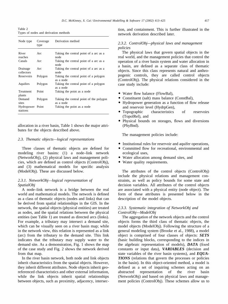
Table 2Types of nodes and derivation methods
Node type Coverage Derivation methodtype
River Arc Taking the central point of a arc as areaches nodeCanals Arc Taking the central point of a arc as a
nodeDrainage Arc Taking the central point of a arc as acollectors nodeReservoirs Polygon Taking the central point of a polygon
as a nodeAquifers Polygon Taking the central point of a polygon
as a nodeTreatment Point Taking the point as a nodeplantsDemand Polygon Taking the central point of the polygonsites as a nodeHydropower Point Taking the point as a nodestations
allocation in a river basin, Table 1 shows the major attri-butes for the objects described above.
2.3. Thematic objects—logical representations
Three classes of thematic objects are defined formodeling river basins: (1) a node–link network(NetworkObj), (2) physical laws and management poli-cies, which are defined as control objects (ControlObj),and (3) mathematical models for specific analysis(ModelObj). These are discussed below.
2.3.1. NetworkObj—logical representation ofSpatialObj
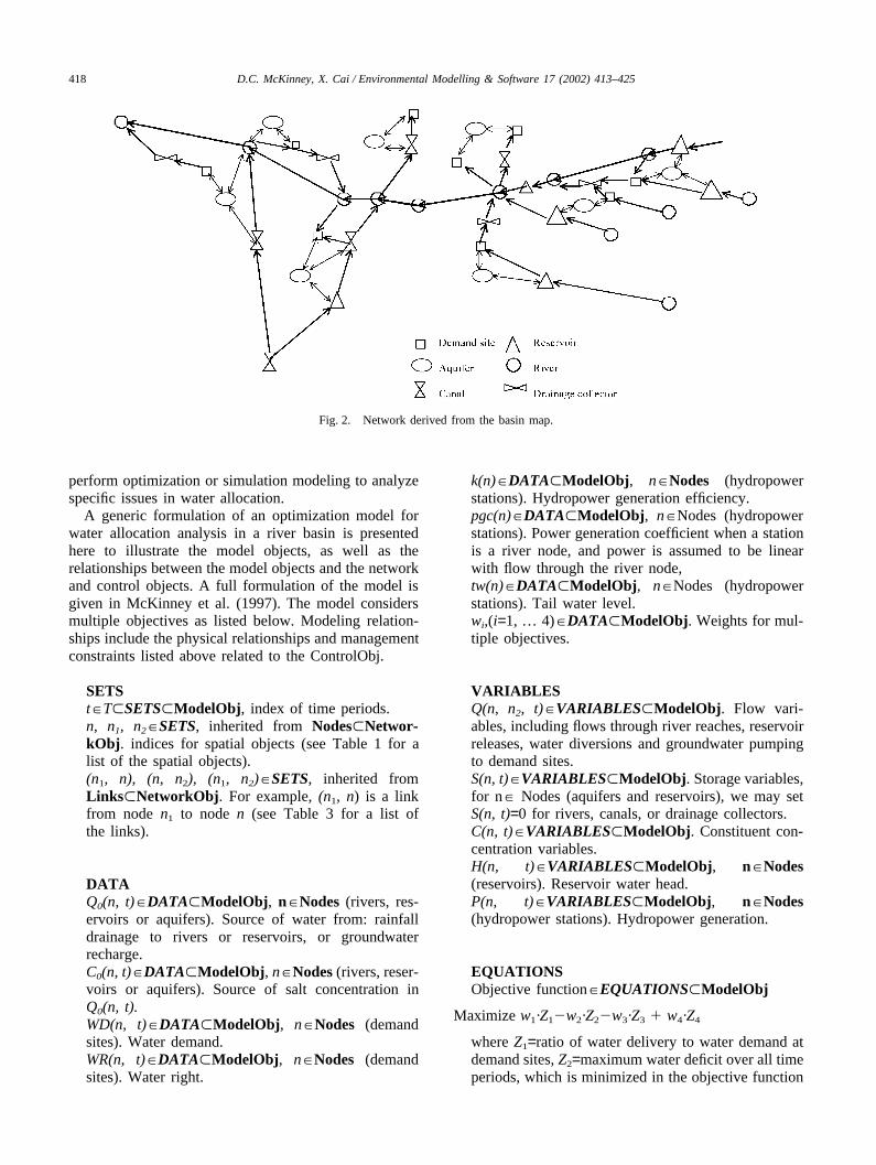
A node–link network is a bridge between the realworld and mathematical models. The network is definedas a class of thematic objects (nodes and links) that canbe derived from spatial relationships in the GIS. In thenetwork, the spatial objects (physical entities) are treatedas nodes, and the spatial relations between the physicalentities (see Table 1) are treated as directed arcs (links).For example, a tributary may intersect a demand site,which can be visually seen on a river basin map; whilein the network view, this relation is represented as a link(arc) from the tributary to the demand site. This linkindicates that the tributary may supply water to thedemand site. As a demonstration, Fig. 1 shows the mapof the case study and Fig. 2 shows the network derivedfrom that map.
In the river basin network, both node and link objectsinherit characteristics from the spatial objects. However,they inherit different attributes. Node objects inherit geo-referenced characteristics and other external information,while the link objects inherit spatial relationshipsbetween objects, such as proximity, adjacency, intersec-
tion, and containment. This is further illustrated in thenetwork derivation described later.
2.3.2. ControlObj—physical laws and managementpolicies
The physical laws that govern spatial objects in thereal world, and the management policies that control theoperation of a river basin system and water allocation ina basin, are defined as a separate class of thematicobjects. Since this class represents natural and anthro-pogenic controls, they are called control objects(ControlObj). The physical relations considered in thecase study include:
� Water flow balance (FlowBal),� Constituent (salt) mass balance (ConstBal),� Hydropower generation as a function of flow release
and reservoir level (HydrpGen),� Topographic characteristics of reservoirs
(TopolRel), and� Physical bounds on storages, flows and diversions
(PhyBnd).
The management policies include:
� Institutional rules for reservoir and aquifer operations,� Committed flow for recreational, environmental and
ecological uses,� Water allocation among demand sites, and� Water quality requirements.
The attributes of the control objects (ControlObj)include the physical relations and management con-straints, as well as policy bounds for some state anddecision variables. All attributes of the control objectsare associated with a physical entity (node object). Theform of these attributes is presented below in thedescription of the model objects.
2.3.3. Systematic integration of NetworkObj andControlObj—ModelObj
The aggregation of the network objects and the controlobjects forms the third class of thematic objects, themodel objects (ModelObj). Following the structure of ageneral modeling system (Brooke et al., 1988), a modelobject is comprised of four classes of objects: SETS(basic building blocks, corresponding to the indices inthe algebraic representation of models), DATA (fixedconstants or input data), VARIABLES (decision andstate variables of the river basin systems), and EQUA-TIONS (relations that govern the processes or policiesin the basin). In this object-oriented method, a model isdefined as a set of inquiring schemes acting on anabstracted representation of the river basin(NetworkObj) and based on physical laws and manage-ment policies (ControlObj). These schemes allow us to
418 D.C. McKinney, X. Cai / Environmental Modelling & Software 17 (2002) 413–425
Fig. 2. Network derived from the basin map.
perform optimization or simulation modeling to analyzespecific issues in water allocation.
A generic formulation of an optimization model forwater allocation analysis in a river basin is presentedhere to illustrate the model objects, as well as therelationships between the model objects and the networkand control objects. A full formulation of the model isgiven in McKinney et al. (1997). The model considersmultiple objectives as listed below. Modeling relation-ships include the physical relationships and managementconstraints listed above related to the ControlObj.
SETSt�T�SETS�ModelObj, index of time periods.n, n1, n2�SETS, inherited from Nodes�Networ-kObj. indices for spatial objects (see Table 1 for alist of the spatial objects).(n1, n), (n, n2), (n1, n2)�SETS, inherited fromLinks�NetworkObj. For example, (n1, n) is a linkfrom node n1 to node n (see Table 3 for a list ofthe links).
DATAQ0(n, t)�DATA�ModelObj, n�Nodes (rivers, res-ervoirs or aquifers). Source of water from: rainfalldrainage to rivers or reservoirs, or groundwaterrecharge.C0(n, t)�DATA�ModelObj, n�Nodes (rivers, reser-voirs or aquifers). Source of salt concentration inQ0(n, t).WD(n, t)�DATA�ModelObj, n�Nodes (demandsites). Water demand.WR(n, t)�DATA�ModelObj, n�Nodes (demandsites). Water right.
k(n)�DATA�ModelObj, n�Nodes (hydropowerstations). Hydropower generation efficiency.pgc(n)�DATA�ModelObj, n�Nodes (hydropowerstations). Power generation coefficient when a stationis a river node, and power is assumed to be linearwith flow through the river node,tw(n)�DATA�ModelObj, n�Nodes (hydropowerstations). Tail water level.wi,(i=1, … 4)�DATA�ModelObj. Weights for mul-tiple objectives.
VARIABLESQ(n, n2, t)�VARIABLES�ModelObj. Flow vari-ables, including flows through river reaches, reservoirreleases, water diversions and groundwater pumpingto demand sites.S(n, t)�VARIABLES�ModelObj. Storage variables,for n� Nodes (aquifers and reservoirs), we may setS(n, t)=0 for rivers, canals, or drainage collectors.C(n, t)�VARIABLES�ModelObj. Constituent con-centration variables.H(n, t)�VARIABLES�ModelObj, n�Nodes(reservoirs). Reservoir water head.P(n, t)�VARIABLES�ModelObj, n�Nodes(hydropower stations). Hydropower generation.
EQUATIONSObjective function�EQUATIONS�ModelObj
Maximize w1·Z1�w2·Z2�w3·Z3 � w4·Z4
where Z1=ratio of water delivery to water demand atdemand sites, Z2=maximum water deficit over all timeperiods, which is minimized in the objective function
419D.C. McKinney, X. Cai / Environmental Modelling & Software 17 (2002) 413–425
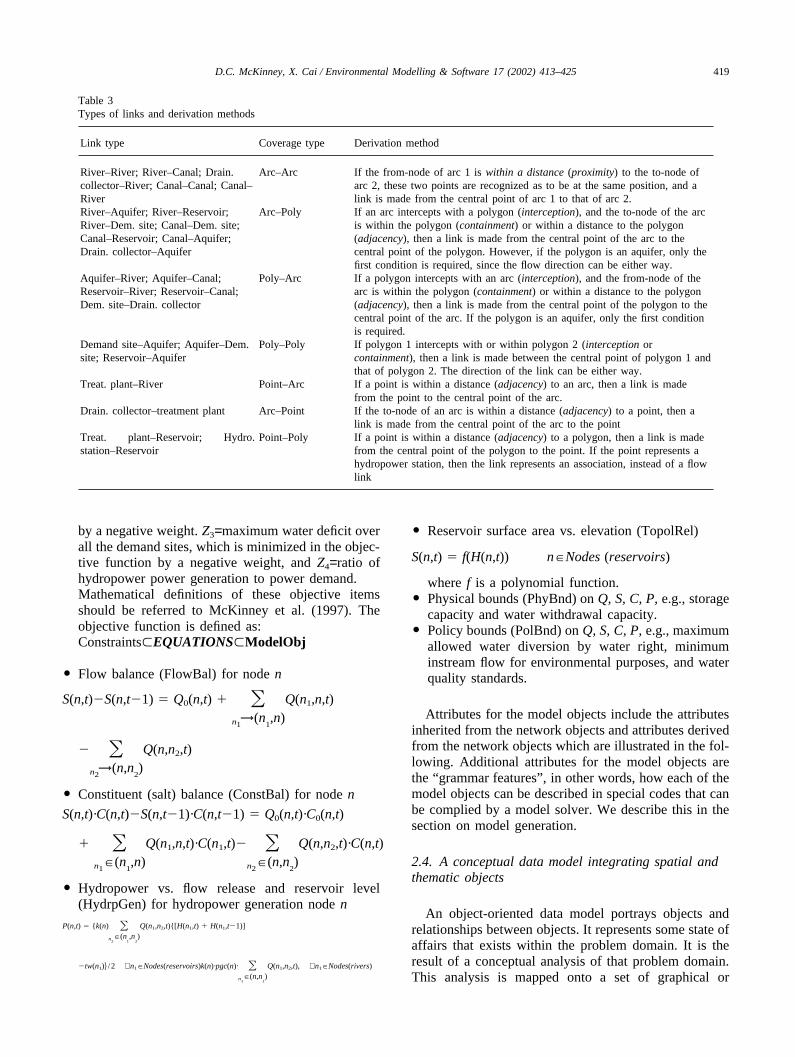
Table 3Types of links and derivation methods
Link type Coverage type Derivation method
River–River; River–Canal; Drain. Arc–Arc If the from-node of arc 1 is within a distance (proximity) to the to-node ofcollector–River; Canal–Canal; Canal– arc 2, these two points are recognized as to be at the same position, and aRiver link is made from the central point of arc 1 to that of arc 2.River–Aquifer; River–Reservoir; Arc–Poly If an arc intercepts with a polygon (interception), and the to-node of the arcRiver–Dem. site; Canal–Dem. site; is within the polygon (containment) or within a distance to the polygonCanal–Reservoir; Canal–Aquifer; (adjacency), then a link is made from the central point of the arc to theDrain. collector–Aquifer central point of the polygon. However, if the polygon is an aquifer, only the
first condition is required, since the flow direction can be either way.Aquifer–River; Aquifer–Canal; Poly–Arc If a polygon intercepts with an arc (interception), and the from-node of theReservoir–River; Reservoir–Canal; arc is within the polygon (containment) or within a distance to the polygonDem. site–Drain. collector (adjacency), then a link is made from the central point of the polygon to the
central point of the arc. If the polygon is an aquifer, only the first conditionis required.
Demand site–Aquifer; Aquifer–Dem. Poly–Poly If polygon 1 intercepts with or within polygon 2 (interception orsite; Reservoir–Aquifer containment), then a link is made between the central point of polygon 1 and
that of polygon 2. The direction of the link can be either way.Treat. plant–River Point–Arc If a point is within a distance (adjacency) to an arc, then a link is made
from the point to the central point of the arc.Drain. collector–treatment plant Arc–Point If the to-node of an arc is within a distance (adjacency) to a point, then a
link is made from the central point of the arc to the pointTreat. plant–Reservoir; Hydro. Point–Poly If a point is within a distance (adjacency) to a polygon, then a link is madestation–Reservoir from the central point of the polygon to the point. If the point represents a
hydropower station, then the link represents an association, instead of a flowlink
by a negative weight. Z3=maximum water deficit overall the demand sites, which is minimized in the objec-tive function by a negative weight, and Z4=ratio ofhydropower power generation to power demand.Mathematical definitions of these objective itemsshould be referred to McKinney et al. (1997). Theobjective function is defined as:Constraints�EQUATIONS�ModelObj
� Flow balance (FlowBal) for node n
S(n,t)�S(n,t�1) � Q0(n,t) � �n1
→(n1,n)
Q(n1,n,t)
� �n2
→(n,n2)Q(n,n2,t)
� Constituent (salt) balance (ConstBal) for node n
S(n,t)·C(n,t)�S(n,t�1)·C(n,t�1) � Q0(n,t)·C0(n,t)
� �n1
�(n1,n)
Q(n1,n,t)·C(n1,t)� �n2
�(n,n2)Q(n,n2,t)·C(n,t)
� Hydropower vs. flow release and reservoir level(HydrpGen) for hydropower generation node n
P(n,t) � {k(n) �n
2�(n
1,n
2)Q(n1,n2,t){[H(n1,t) � H(n1,t�1)]
�tw(n1)� / 2 ∀ n1�Nodes(reservoirs)k(n)·pgc(n)· �n
1�(n,n
1)Q(n1,n2,t), ∀ n1�Nodes(rivers)
� Reservoir surface area vs. elevation (TopolRel)
S(n,t) � f(H(n,t)) n�Nodes (reservoirs)
where f is a polynomial function.� Physical bounds (PhyBnd) on Q, S, C, P, e.g., storage
capacity and water withdrawal capacity.� Policy bounds (PolBnd) on Q, S, C, P, e.g., maximum
allowed water diversion by water right, minimuminstream flow for environmental purposes, and waterquality standards.
Attributes for the model objects include the attributesinherited from the network objects and attributes derivedfrom the network objects which are illustrated in the fol-lowing. Additional attributes for the model objects arethe “grammar features” , in other words, how each of themodel objects can be described in special codes that canbe complied by a model solver. We describe this in thesection on model generation.
2.4. A conceptual data model integrating spatial andthematic objects
An object-oriented data model portrays objects andrelationships between objects. It represents some state ofaffairs that exists within the problem domain. It is theresult of a conceptual analysis of that problem domain.This analysis is mapped onto a set of graphical or
420 D.C. McKinney, X. Cai / Environmental Modelling & Software 17 (2002) 413–425
linguistic conventions, and is able to faithfully representthe characteristics and complexity of the phenomena.
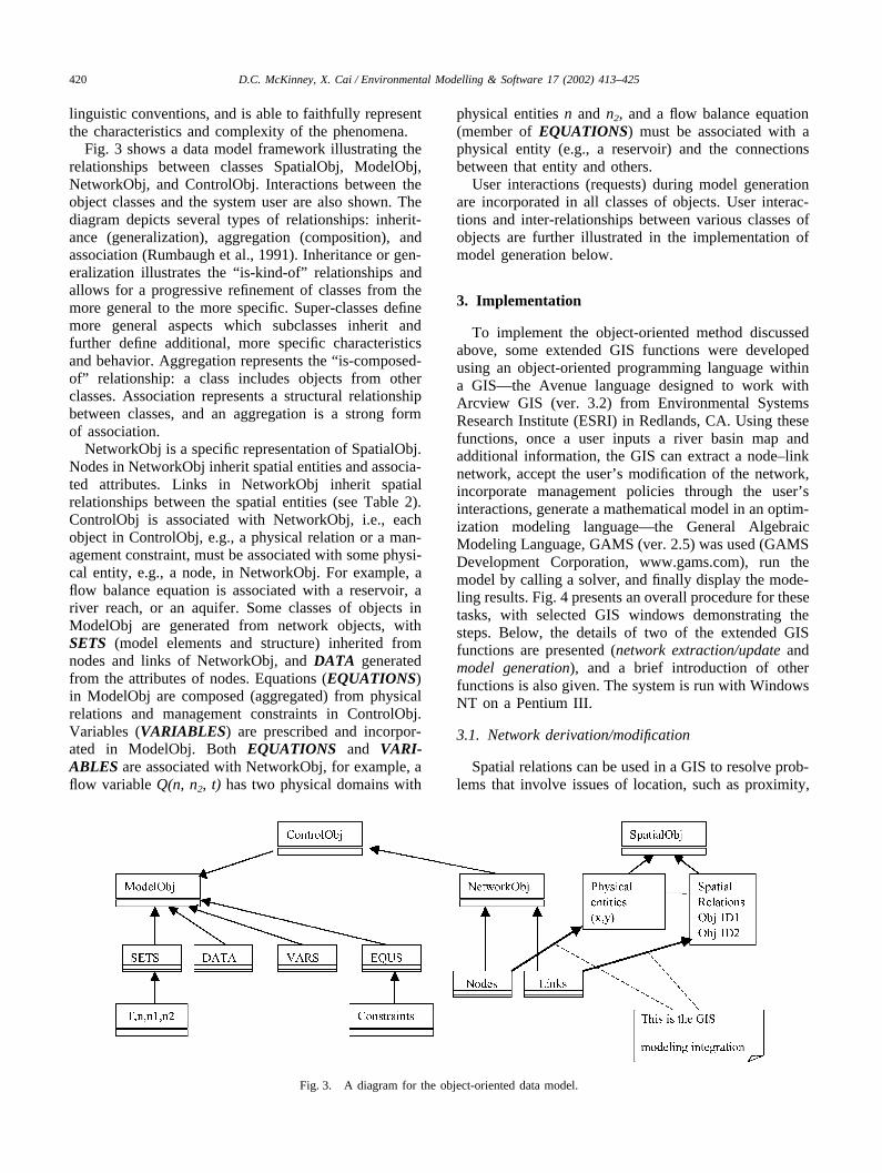
Fig. 3 shows a data model framework illustrating therelationships between classes SpatialObj, ModelObj,NetworkObj, and ControlObj. Interactions between theobject classes and the system user are also shown. Thediagram depicts several types of relationships: inherit-ance (generalization), aggregation (composition), andassociation (Rumbaugh et al., 1991). Inheritance or gen-eralization illustrates the “ is-kind-of” relationships andallows for a progressive refinement of classes from themore general to the more specific. Super-classes definemore general aspects which subclasses inherit andfurther define additional, more specific characteristicsand behavior. Aggregation represents the “ is-composed-of” relationship: a class includes objects from otherclasses. Association represents a structural relationshipbetween classes, and an aggregation is a strong formof association.
NetworkObj is a specific representation of SpatialObj.Nodes in NetworkObj inherit spatial entities and associa-ted attributes. Links in NetworkObj inherit spatialrelationships between the spatial entities (see Table 2).ControlObj is associated with NetworkObj, i.e., eachobject in ControlObj, e.g., a physical relation or a man-agement constraint, must be associated with some physi-cal entity, e.g., a node, in NetworkObj. For example, aflow balance equation is associated with a reservoir, ariver reach, or an aquifer. Some classes of objects inModelObj are generated from network objects, withSETS (model elements and structure) inherited fromnodes and links of NetworkObj, and DATA generatedfrom the attributes of nodes. Equations (EQUATIONS)in ModelObj are composed (aggregated) from physicalrelations and management constraints in ControlObj.Variables (VARIABLES) are prescribed and incorpor-ated in ModelObj. Both EQUATIONS and VARI-ABLES are associated with NetworkObj, for example, aflow variable Q(n, n2, t) has two physical domains with
Fig. 3. A diagram for the object-oriented data model.
physical entities n and n2, and a flow balance equation(member of EQUATIONS) must be associated with aphysical entity (e.g., a reservoir) and the connectionsbetween that entity and others.
User interactions (requests) during model generationare incorporated in all classes of objects. User interac-tions and inter-relationships between various classes ofobjects are further illustrated in the implementation ofmodel generation below.
3. Implementation
To implement the object-oriented method discussedabove, some extended GIS functions were developedusing an object-oriented programming language withina GIS—the Avenue language designed to work withArcview GIS (ver. 3.2) from Environmental SystemsResearch Institute (ESRI) in Redlands, CA. Using thesefunctions, once a user inputs a river basin map andadditional information, the GIS can extract a node–linknetwork, accept the user’s modification of the network,incorporate management policies through the user’sinteractions, generate a mathematical model in an optim-ization modeling language—the General AlgebraicModeling Language, GAMS (ver. 2.5) was used (GAMSDevelopment Corporation, www.gams.com), run themodel by calling a solver, and finally display the mode-ling results. Fig. 4 presents an overall procedure for thesetasks, with selected GIS windows demonstrating thesteps. Below, the details of two of the extended GISfunctions are presented (network extraction/update andmodel generation), and a brief introduction of otherfunctions is also given. The system is run with WindowsNT on a Pentium III.
3.1. Network derivation/modification
Spatial relations can be used in a GIS to resolve prob-lems that involve issues of location, such as proximity,
421D.C. McKinney, X. Cai / Environmental Modelling & Software 17 (2002) 413–425
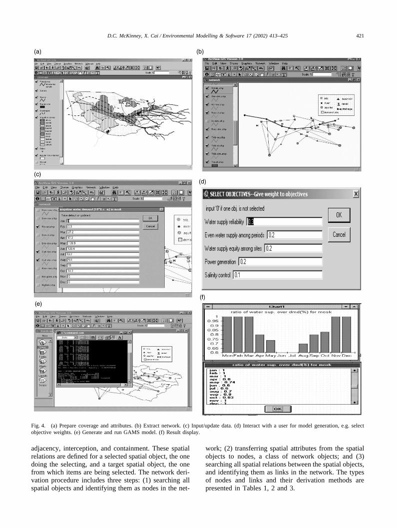
Fig. 4. (a) Prepare coverage and attributes. (b) Extract network. (c) Input/update data. (d) Interact with a user for model generation, e.g. selectobjective weights. (e) Generate and run GAMS model. (f) Result display.
adjacency, interception, and containment. These spatialrelations are defined for a selected spatial object, the onedoing the selecting, and a target spatial object, the onefrom which items are being selected. The network deri-vation procedure includes three steps: (1) searching allspatial objects and identifying them as nodes in the net-
work; (2) transferring spatial attributes from the spatialobjects to nodes, a class of network objects; and (3)searching all spatial relations between the spatial objects,and identifying them as links in the network. The typesof nodes and links and their derivation methods arepresented in Tables 1, 2 and 3.
422 D.C. McKinney, X. Cai / Environmental Modelling & Software 17 (2002) 413–425
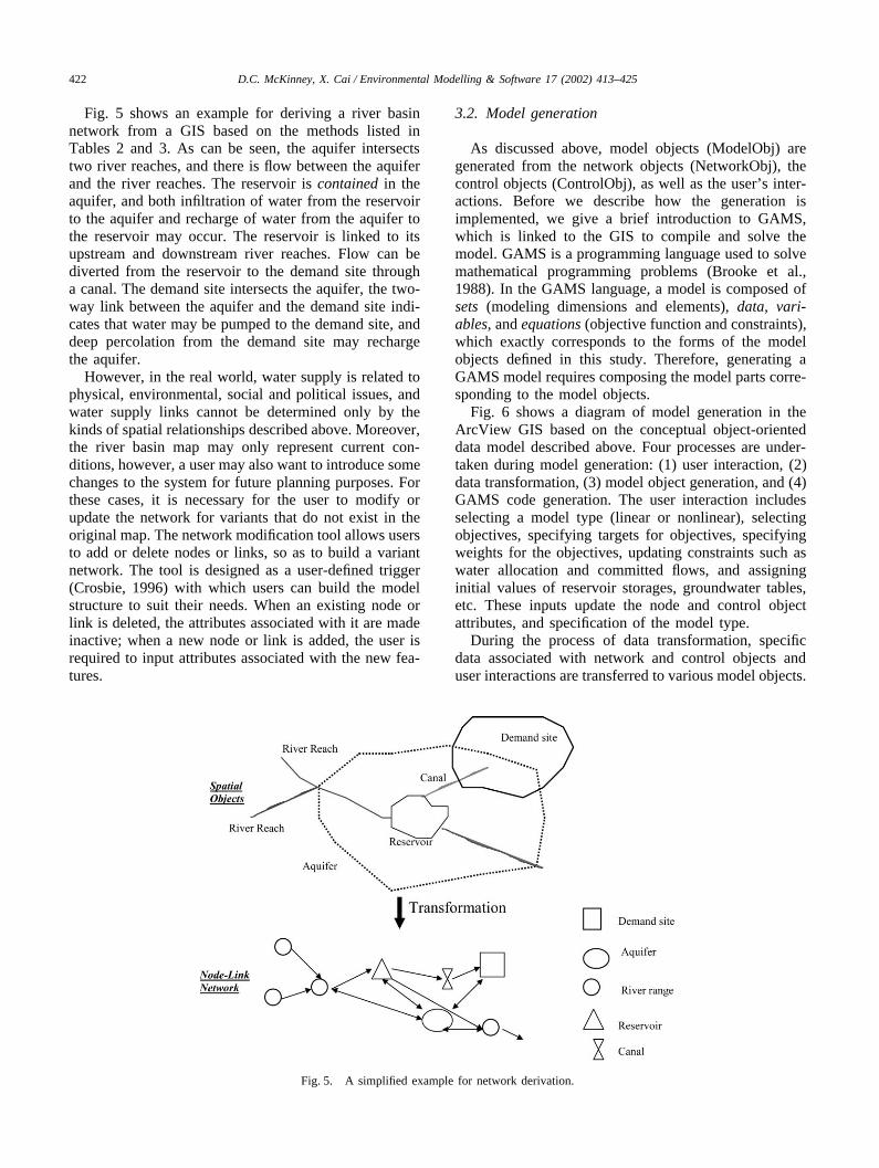
Fig. 5 shows an example for deriving a river basinnetwork from a GIS based on the methods listed inTables 2 and 3. As can be seen, the aquifer intersectstwo river reaches, and there is flow between the aquiferand the river reaches. The reservoir is contained in theaquifer, and both infiltration of water from the reservoirto the aquifer and recharge of water from the aquifer tothe reservoir may occur. The reservoir is linked to itsupstream and downstream river reaches. Flow can bediverted from the reservoir to the demand site througha canal. The demand site intersects the aquifer, the two-way link between the aquifer and the demand site indi-cates that water may be pumped to the demand site, anddeep percolation from the demand site may rechargethe aquifer.
However, in the real world, water supply is related tophysical, environmental, social and political issues, andwater supply links cannot be determined only by thekinds of spatial relationships described above. Moreover,the river basin map may only represent current con-ditions, however, a user may also want to introduce somechanges to the system for future planning purposes. Forthese cases, it is necessary for the user to modify orupdate the network for variants that do not exist in theoriginal map. The network modification tool allows usersto add or delete nodes or links, so as to build a variantnetwork. The tool is designed as a user-defined trigger(Crosbie, 1996) with which users can build the modelstructure to suit their needs. When an existing node orlink is deleted, the attributes associated with it are madeinactive; when a new node or link is added, the user isrequired to input attributes associated with the new fea-tures.
Fig. 5. A simplified example for network derivation.
3.2. Model generation
As discussed above, model objects (ModelObj) aregenerated from the network objects (NetworkObj), thecontrol objects (ControlObj), as well as the user’s inter-actions. Before we describe how the generation isimplemented, we give a brief introduction to GAMS,which is linked to the GIS to compile and solve themodel. GAMS is a programming language used to solvemathematical programming problems (Brooke et al.,1988). In the GAMS language, a model is composed ofsets (modeling dimensions and elements), data, vari-ables, and equations (objective function and constraints),which exactly corresponds to the forms of the modelobjects defined in this study. Therefore, generating aGAMS model requires composing the model parts corre-sponding to the model objects.
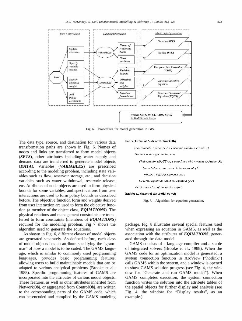
Fig. 6 shows a diagram of model generation in theArcView GIS based on the conceptual object-orienteddata model described above. Four processes are under-taken during model generation: (1) user interaction, (2)data transformation, (3) model object generation, and (4)GAMS code generation. The user interaction includesselecting a model type (linear or nonlinear), selectingobjectives, specifying targets for objectives, specifyingweights for the objectives, updating constraints such aswater allocation and committed flows, and assigninginitial values of reservoir storages, groundwater tables,etc. These inputs update the node and control objectattributes, and specification of the model type.
During the process of data transformation, specificdata associated with network and control objects anduser interactions are transferred to various model objects.
423D.C. McKinney, X. Cai / Environmental Modelling & Software 17 (2002) 413–425
Fig. 6. Procedures for model generation in GIS.
The data type, source, and destination for various datatransformation paths are shown in Fig. 6. Names ofnodes and links are transferred to form model objects(SETS), other attributes including water supply anddemand data are transferred to generate model objects(DATA). Variables (VARIABLES) are prescribedaccording to the modeling problem, including state vari-ables such as flow, reservoir storage, etc., and decisionvariables such as water withdrawal, reservoir release,etc. Attributes of node objects are used to form physicalbounds for some variables, and specifications from userinteractions are used to form policy bounds as describedbefore. The objective function form and weights derivedfrom user interaction are used to form the objective func-tion (a member of the object class, EQUATIONS). Thephysical relations and management constraints are trans-ferred to form constraints (members of EQUATIONS)required for the modeling problem. Fig 7 shows thealgorithm used to generate the equations.
As shown in Fig. 6, different classes of model objectsare generated separately. As defined before, each classof model objects has an attribute specifying the “gram-mar” of how a model is to be coded. The GAMS langu-age, which is similar to commonly used programminglanguages, provides basic programming features,allowing users to build maintainable models that can beadapted to various analytical problems (Brooke et al.,1988). Specific programming features of GAMS areincorporated into the attributes of various model objects.These features, as well as other attributes inherited fromNetworkObj, or aggregated from ControlObj, are writtento the corresponding parts of the GAMS code, whichcan be encoded and complied by the GAMS modeling
Fig. 7. Algorithm for equation generation.
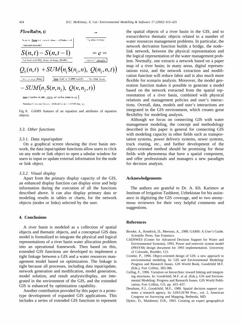
package. Fig. 8 illustrates several special features usedwhen expressing an equation in GAMS, as well as theassociation with the attributes of EQUATIONS, gener-ated through the data model.
GAMS consists of a language compiler and a stableof integrated solvers (Brooke et al., 1988). When theGAMS code for an optimization model is generated, asystem connection function in ArcView (“hotlink” )calls GAMS within the system, and a window is openedto show GAMS solution progress (see Fig. 4, the win-dow for “Generate and run GAMS model” ). WhenGAMS completes execution, the system connectionfunction writes the solution into the attribute tables ofthe spatial objects for further display and analysis (seeFig. 4, the window for “Display results” , as anexample.)
424 D.C. McKinney, X. Cai / Environmental Modelling & Software 17 (2002) 413–425
Fig. 8. GAMS features of an equation and attributes of equationobjects.
3.3. Other functions
3.3.1. Data input/updateOn a graphical screen showing the river basin net-
work, the data input/update functions allow users to clickon any node or link object to open a tabular window forusers to input or update external information for the nodeor link object.
3.3.2. Visual displayApart from the primary display capacity of the GIS,
an enhanced display function can display error and helpinformation during the execution of all the functionsdescribed above. It can also display primary data ormodeling results in tables or charts, for the networkobjects (nodes or links) selected by the user.
4. Conclusions
A river basin is modeled as a collection of spatialobjects and thematic objects, and a conceptual GIS datamodel is formulized to integrate the physical and logicalrepresentations of a river basin water allocation probleminto an operational framework. Then based on this,extended GIS functions are developed to implement atight linkage between a GIS and a water resources man-agement model based on optimization. The linkage istight because all processes, including data input/update,network generation and modification, model generation,model solution, and result analysis/display, are inte-grated in the environment of the GIS, and the extendedGIS is enhanced by optimization capability.
Another contribution provided by this paper is a proto-type development of expanded GIS applications. Thisincludes a series of extended GIS functions to represent
the spatial objects of a river basin in the GIS, and toextract/derive thematic objects related to a number ofwater resources management problems. In particular, thenetwork derivation function builds a bridge, the node–link network, between the physical representation andthe logical representation of the water management prob-lem. Normally, one extracts a network based on a papermap of a river basin; in many areas, digital represen-tations exist, and the network extraction and modifi-cation function will reduce labor and is also much moreflexible for scenario analysis. Moreover, the model gen-eration function makes it possible to generate a modelbased on the network extracted from the spatial rep-resentation of a river basin, combined with physicalrelations and management policies and user’s interac-tions. Overall, data, models and user’s interactions areintegrated in the GIS environment, which creates greatflexibility for modeling analysis.
Although we focus on connecting GIS with watermanagement modeling, the concept and methodologydescribed in this paper is general for connecting GISwith modeling capacity in other fields such as transpor-tation systems, power delivery systems, sewer systems,truck routing, etc., and further development of theobject-oriented method should be promising for thosefields with phenomena that have a spatial component,and offer professionals and managers a new paradigmfor decision analysis.
Acknowledgements
The authors are grateful to Dr. A. Kh. Karimov atInstitute of Irrigation Tashkent, Uzbekistan for his assist-ance in digitizing the GIS coverage, and to two anony-mous reviewers for their very helpful comments andsuggestions.
References
Brooke, A., Kendrick, D., Meeraus, A., 1988. GAMS: A User’s Guide.Scientific Press, San Fransisco.
CADSWES (Center for Advanced Decision Support for Water andEnvironmental Systems), 1993. Power and reservoir system model(PRSYM) design document for 1993 implementation. Universityof Colorado, Boulder, CO.
Crosbie, P., 1996. Object-oriented design of GIS: a new approach toenvironmental modeling. In: GIS and Environmental Modeling:Progress and Research Issues. GIS World Book, Goodchild M.F.(Eds.), Fort Collins, 383-386.
Csillag, F., 1996. Variation on hierarchies: toward linking and integrat-ing structures. In: Goodchild, M.F. et al. (Eds.), GIS and Environ-mental Modeling: Progress and Research Issues. GIS World Publi-cation, Fort Collins, CO, pp. 433–437.
Densham, P.J., Goodchild, M.F., 1989. Spatial decision support sys-tems: a research agency. In: GIS/LIS’89 Proc., vol. 2, AmericanCongress on Surveying and Mapping, Bethesda, MD.
Djokic, D., Maidment, D.R., 1993. Creating an expert geographical

425D.C. McKinney, X. Cai / Environmental Modelling & Software 17 (2002) 413–425
information system: the ARC/INFO–Nexpert object interface. In:ASCE Monograph on Integration Issues in Expert Systems Tech-nology. ASCE, New York.
Environmental Systems Research Institute (ESRI) 2000. Getting toKnow ArcView GIS. ESRI Press, Redland, CA.
Fedra, K., 1996. Distributed models and embedded GIS: integrationstrategies and case studies. In: Goodchild, M.F. et al. (Eds.), GISand Environmental Modeling: Progress and Research Issues. GISWorld Book, Fort Collins, pp. 414–417.
Fedra, K., Jamieson, D.G., 1996. An object-oriented approach to modelintegration: a river basin information system example. In: HydroG-IS’96, IAHS publ. No. 235, 669–676.
Goodchild, M.F., 1993. Data models and data quality: problems andprospects. In: Goodchild, M.F., Parks, B.O., Steyaert, L.T. (Eds.),Environmental Modeling with GIS. Oxford University Press, NewYork, pp. 8–15.
Keller, P.C., Strapp, J.D., 1996. Multicriteria decision support for landreform using GIS and API. In: Goodchild, M.F. et al. (Eds.), GISand Environmental Modeling: Progress and Research Issues. GISWorld Book, Fort Collins, pp. 363–371.
Leipnik, M.R., Kemp, K.K., Loaiciga, H.A., 1993. Implementation ofGIS for water resources planning and management. J. Wat. Resour.Plan. Mgmt 119 (2), 184–205.
Loucks, D.P., 1996. Surface water systems. In: Mays, L. (Ed.), WaterResources Handbook, Chap. 15. McGraw-Hill, New York.
McKinney, D.C., Karimov, A.Kh., Cai, X., 1997. Report on modeldevelopment: Aral Sea regional allocation model for the AmudaryaRiver. Technical Report, US Agency for International Develop-ment, Environmental Policy and Technology Project, Central AsiaRegional EPT Office, Almaty, Kazakstan.
McKinney, D.C., Tsai, H.L., 1996. Multigrid method grid-cell-basedmodeling environment. J. Comput. Civil Engng 10 (1), 80–86.
Miles, S.B., Ho, C.L., 2001. Applications and issues of GIS as toolfor civil engineering modeling. J. Comput. Civil Engng 13 (3),144–152.
Nyerges, T.L., 1993. Understanding the scope of GIS: its relationshipto environmental modeling. In: Goodchild, M.F., Parks, B.O., Ste-yaert, L.T. (Eds.), Environmental Modeling with GIS. Oxford Uni-versity Press, New York, pp. 75–84.
Sample, D.J., Heaney, J.P., Leonard, T.W., Koustas, R., 2001. Geo-graphic information systems, decision support systems, and urbanstorm-water management. J. Wat. Resour. Plan. Mgmt 127 (3),155–161.
Reitsma, R., 1996. Bootstrapping river basin models with object orien-tation and GIS topology. In: Goodchild, M.F. et al. (Eds.), GIS andEnvironmental Modeling: Progress and Research Issues. GISWorld Book, Fort Collins, pp. 457–461.
Reitsma, R.F., Sautins, A.M., Wehrend, S.C., 1994. Construction kitfor visual programming of river-basin models. J. Comput. CivilEngng 8 (3), 378–384.
Rumbaugh, J., Blaha, M., Premerlani, W., Eddy, F., Lorensen, W.,1991. Object-Oriented Modeling and Design. Prentice Hall, Engle-wood Cliffs, NJ.
Tisdale, T.S., 1996. Object-oriented analysis of south Floridahydrologic systems. J. Comput. Civil Engng 10 (4), 318–326.
Walsh, M.R., 1992. Toward spatial decision support systems in waterresources. J. Wat. Resour. Plan. Mgmt 109 (2), 158–169.
Watkins, D.W. Jr., McKinney, D.C., 1995. Recent developments indecision support systems for water resources. US National Contri-butions in Hydrology 1991–1994, Reviews of Geophysics, Sup-plement, 941–948.
Watkins, D.W. Jr., McKinney, D.C., Maidment, D.R., Lin, M.-D.,1996. GIS and groundwater modeling. J. Water Resour. Plan.Mgmt 122 (2), 88–96.
Ye, Z., Maidment, D.R., McKinney, D.C., 1996. Map-based surfaceand subsurface flow simulation models: an object oriented and GISapproach. Center for Research in Water Resources, The Universityof Texas, Austin, TX.