Link State Routing - Engineering and Advanced Technology - Massey
27
159.334 Computer Networks 159.334 Computer Networks Link State Routing Professor Richard Harris School of Engineering and Advanced Technology (SEAT)
Transcript of Link State Routing - Engineering and Advanced Technology - Massey

159.334 Computer Networks159.334 Computer Networks
Link State Routing
Professor Richard Harris
School of Engineering and AdvancedTechnology (SEAT)

Computer NetworksComputer Networks -- 1/1/22
159.334 Computer Networks159.334 Computer Networks
Presentation Outline
Link State Routing Protocols

Computer NetworksComputer Networks -- 1/1/33
159.334 Computer Networks159.334 Computer Networks
Learning Objectives
You will be able to:
Describe the operation of OSPF
Discuss the differences between link state routing andother forms of routing

Computer NetworksComputer Networks -- 1/1/44
159.334 Computer Networks159.334 Computer Networks
References
Tanenbaum, “Computer Networks”, 4th Edition
Forouzan, “Data Communications and Networking”, 4th
Edition
Cisco CCNA1 Module 10 - part 1
Stallings, William 2000 ‘Data and ComputerCommunications’, Prentice Hall, Sixth Edition
Russell, Travis 1997 ‘Telecommunications Protocols’,McGraw Hill

Computer NetworksComputer Networks -- 1/1/55
159.334 Computer Networks159.334 Computer Networks
Introduction to Link State RoutingProtocols - 2
Link state protocols are based upon theprinciple of a “distributed map”.
All of the nodes in the network have a copy ofthe map and it is regularly updated. The map isrepresented as a database.
We shall examine this database in the followingslides and explain how it is updated using theflooding protocol.
The Link State protocols are known as“Shortest Path First” algorithms as they arebased upon a well-known shortest pathalgorithm developed by Dijkstra.
Computer NetworksComputer Networks -- 1/1/66
159.334 Computer Networks159.334 Computer Networks
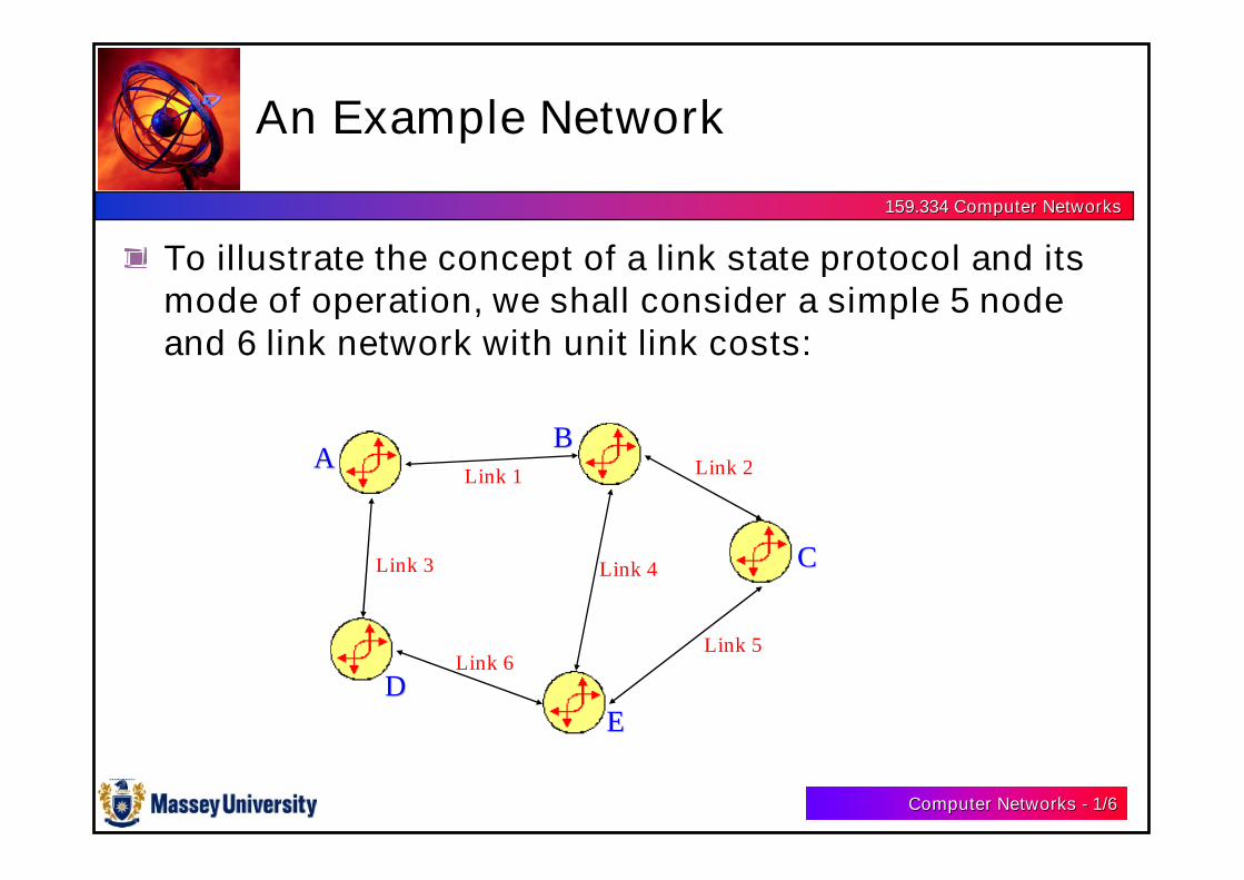
An Example Network
AABB
CC
EEDD
Link 1 Link 2
Link 5
Link 4
Link 6
Link 3
To illustrate the concept of a link state protocol and itsmode of operation, we shall consider a simple 5 nodeand 6 link network with unit link costs:

Computer NetworksComputer Networks -- 1/1/77
159.334 Computer Networks159.334 Computer Networks
The Database - 1
The idea behind Link StateRouting is to have all the nodesmaintain a complete copy of thenetwork map and perform acomputation of the best routesbased on this local copy of themap.
The database oppositerepresents the network shownon the previous slide.
From To Link Distance NumberA B 1 1 2
A D 3 1 1
B A 1 1 2
B C 2 1 2
B E 4 1 1
C B 2 1 2
C E 5 1 1
D A 3 1 1
D E 6 1 1
E B 4 1 1
E C 5 1 1
E D 6 1 2
Computer NetworksComputer Networks -- 1/1/88
159.334 Computer Networks159.334 Computer Networks
The Database - 2
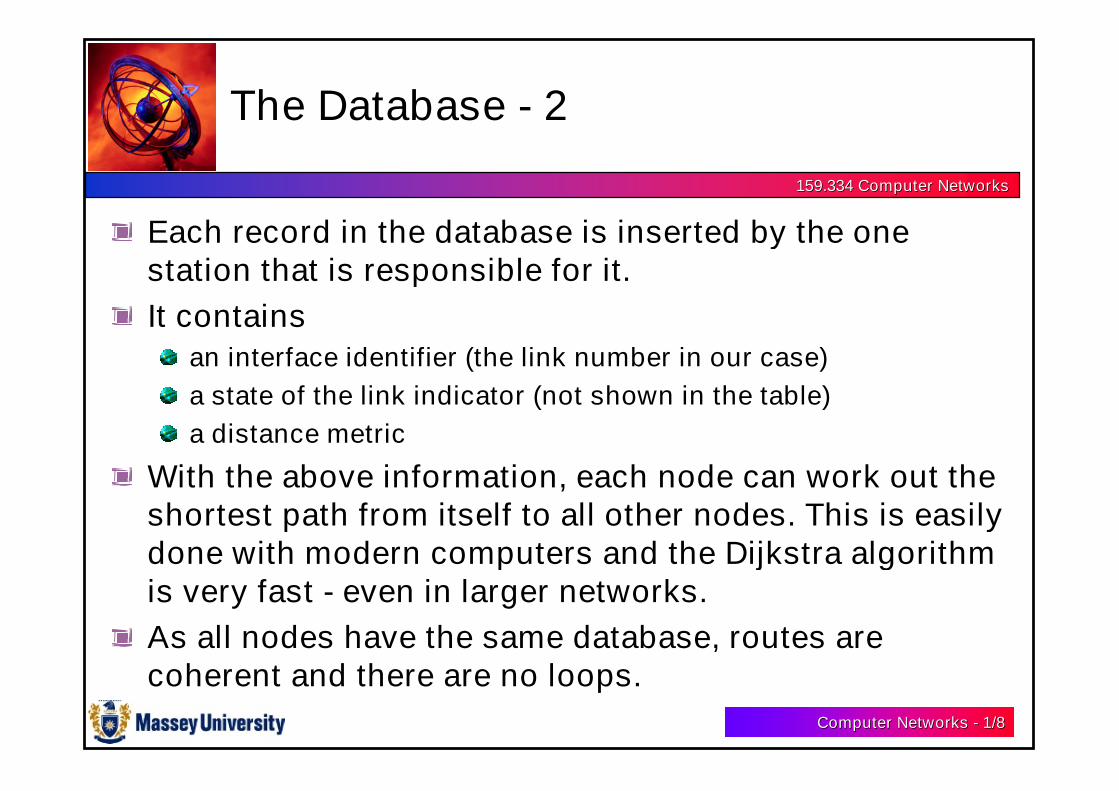
Each record in the database is inserted by the onestation that is responsible for it.
It containsan interface identifier (the link number in our case)
a state of the link indicator (not shown in the table)
a distance metric
With the above information, each node can work out theshortest path from itself to all other nodes. This is easilydone with modern computers and the Dijkstra algorithmis very fast - even in larger networks.
As all nodes have the same database, routes arecoherent and there are no loops.
Computer NetworksComputer Networks -- 1/1/99
159.334 Computer Networks159.334 Computer Networks
The Flooding Protocol - 1
The main objective of a routing protocol is to generateroutes on the basis of the prevailing conditions in anetwork.
To achieve this objective, Link State protocols mustsend out update information whenever there is a changein the link state.
For example, if Link 1 fails in our network, then amessage must be generated by nodes A and B to informthe other nodes of this change in condition.

Computer NetworksComputer Networks -- 1/1/1010
159.334 Computer Networks159.334 Computer Networks
The Flooding Protocol - 2
AABB
CC
EEDD
Link 1 Link 2
Link 5
Link 4
Link 6
Link 3
From A to B, Link 1, distance = inf
From B to A, Link 1, distance = inf
From A to B, Link 1, distance = inf
From B to A, Link 1, distance = inf

Computer NetworksComputer Networks -- 1/1/1111
159.334 Computer Networks159.334 Computer Networks
Flooding Algorithm - 1
The previous slide showed the messages circulating after the update.
Note, however, that the messages should be time-stamped otherwise oldmessages could pollute the database.
The algorithm for flooding can therefore be summarised as:
Receive message. Look for record in database.
If the record is not yet included, add it to the database, broadcast the message.
Else if the number in the base is lower than the number in the message, replacethe value with the new one and broadcast the message.
Else if the number in the base is higher, transmit the current database valuethrough the incoming interface.
Else if both numbers were the same, do nothing.

Computer NetworksComputer Networks -- 1/1/1212
159.334 Computer Networks159.334 Computer Networks
Flooding Algorithm - 2
Note that the broadcast operation will cause the transmission ofthe message on all interfaces except the incoming one.
If we assume that the message identifier for the first record in thedatabase at A was “1”, then the message sent by A to D would be:
From A to B: Link 1, distance=inf; message #=2
D will update its database and transmit the message to E. E willalso update its database and transmit the message to B and C.
When they receive the second message, B and C will notice thatthe number is the same as in their current databases so that theflooding operation will terminate according to the algorithm.
Computer NetworksComputer Networks -- 1/1/1313
159.334 Computer Networks159.334 Computer Networks
Bringing up Adjacencies - 1
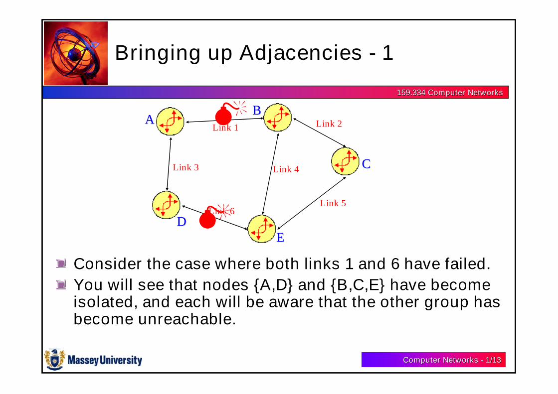
Consider the case where both links 1 and 6 have failed.
You will see that nodes {A,D} and {B,C,E} have becomeisolated, and each will be aware that the other group hasbecome unreachable.
AABB
CC
EEDD
Link 1 Link 2
Link 5
Link 4
Link 6
Link 3

Computer NetworksComputer Networks -- 1/1/1414
159.334 Computer Networks159.334 Computer Networks
Bringing up Adjacencies - 2
There will be two distinctly different versions of thedatabase:
From To Link Distance NumberA B 1 inf 2
A D 3 1 1
B A 1 inf 2
B C 2 1 2
B E 4 1 1
C B 2 1 2
C E 5 1 1
D A 3 1 1
D E 6 inf 1
E B 4 1 1
E C 5 1 1
E D 6 1 2
Routing seen from {A,D}
From To Link Distance NumberA B 1 inf 2
A D 3 1 1
B A 1 inf 2
B C 2 1 2
B E 4 1 1
C B 2 1 2
C E 5 1 1
D A 3 1 1
D E 6 1 1
E B 4 1 1
E C 5 1 1
E D 6 inf 2
Routing seen from {B,C,E}

Computer NetworksComputer Networks -- 1/1/1515
159.334 Computer Networks159.334 Computer Networks
Bringing up Adjacencies - 3
Notice that in this situation,there is no possibility of a“count to infinity” as indistance vector protocols.
Consider the case whereLink 2 also fails.
An interesting problemoccurs when restoration isundertaken for link 1 in thesecircumstances.
From To Link Distance NumberA B 1 inf 2
A D 3 1 1
B A 1 inf 2
B C 2 inf 2
B E 4 1 1
C B 2 inf 2
C E 5 1 1
D A 3 1 1
D E 6 1 1
E B 4 1 1
E C 5 1 1
E D 6 inf 2
Routing seen from {B,C,E}

Computer NetworksComputer Networks -- 1/1/1616
159.334 Computer Networks159.334 Computer Networks
Bringing up Adjacencies - 4
Consider the resetting of link 1 so that it has become operational.
It can be shown that merely distributing this new link information isinsufficient.
We have to guarantee that the two groups end up with the samedatabases. This alignment process is referred to as “Bringing upAdjacencies” in OSPF.
The idea is that the groups must synchronise their databases bykeeping only the most up to date version of each record.
OSPF does this by defining database description packets.
During the first phase of the synchronisation procedure, bothrouters send a complete description of their database records in asequence of description packets.
Computer NetworksComputer Networks -- 1/1/1717
159.334 Computer Networks159.334 Computer Networks
Bringing up Adjacencies - 5
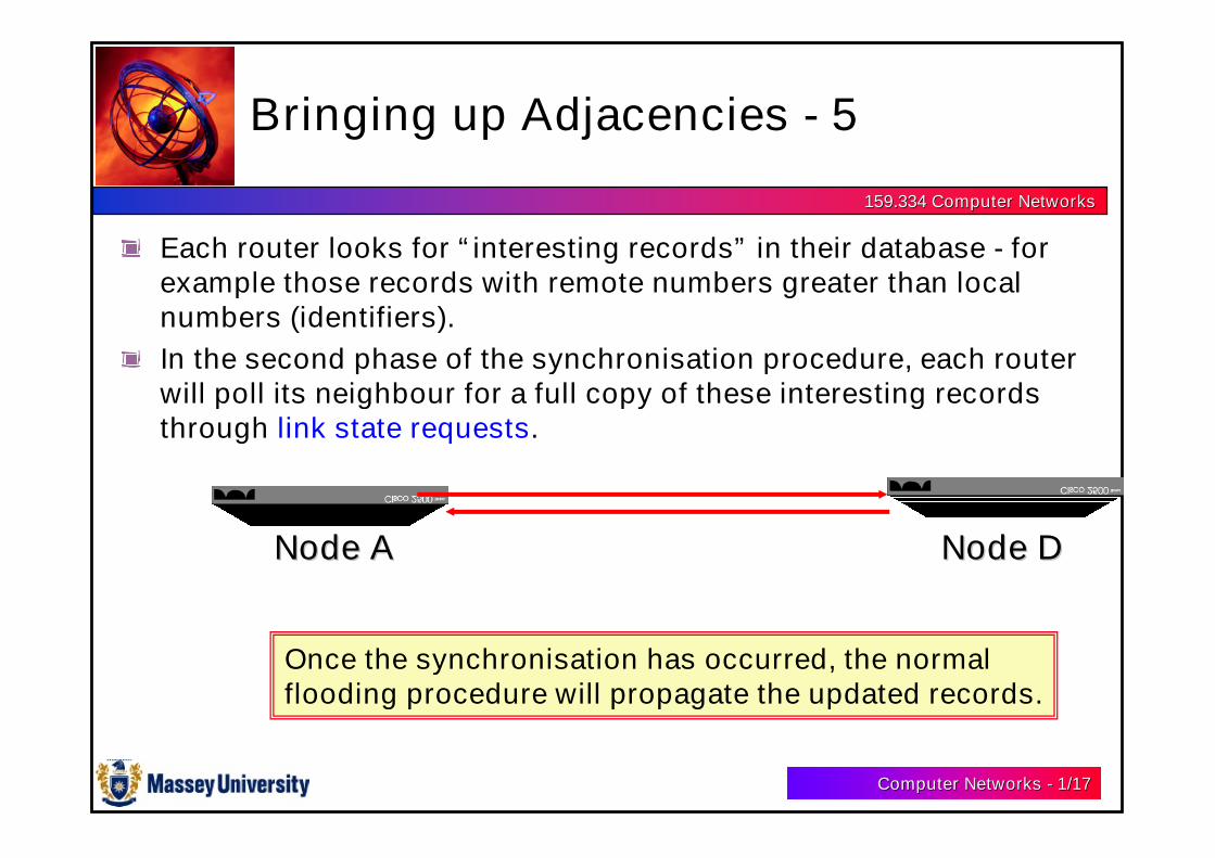
Each router looks for “interesting records” in their database - forexample those records with remote numbers greater than localnumbers (identifiers).
In the second phase of the synchronisation procedure, each routerwill poll its neighbour for a full copy of these interesting recordsthrough link state requests.
Node ANode A Node DNode D
Once the synchronisation has occurred, the normalflooding procedure will propagate the updated records.

Computer NetworksComputer Networks -- 1/1/1818
159.334 Computer Networks159.334 Computer Networks
Map Updates
To prevent accidental corruption of the databases in thenetwork, a scheme developed by Radia Perlman hasbeen introduced:
The flooding procedure includes hop-by-hop acknowledgment.
Database description packets are sent in a secure fashion.
Each link state record is protected by a timer is is removed fromthe system if a refreshing packet is not sent in time.
All records are protected by a checksum.
The messages can be authenticated by a password.
Computer NetworksComputer Networks -- 1/1/1919
159.334 Computer Networks159.334 Computer Networks
“Open Shortest Path First” - OSPF
We have seen that the distance vector protocols are based upon theBellman-Ford procedure. The link state protocols are based uponthe method of Dijkstra.
It turns out that Dijkstra’s algorithm is generally faster thanBellman-Ford’s approach. In fact, if there are N nodes and M links,Bellman-Ford requires o(NM) iterations, whilst Dijkstra requires o(Mlog M) iterations. For large networks, this difference is quitesignificant.
Dijkstra called his method “Shortest Path First”.
The IETF coined the phrase “Open Shortest Path First” because itwas developed in an “open” fashion.
Computer NetworksComputer Networks -- 1/1/2020
159.334 Computer Networks159.334 Computer Networks
Advantages of Link State Protocols
It appears that most network specialists favour the link stateprotocols.
The reasons are:
Fast, loopless convergence.
Two phases are used: (a) Rapid transmission via flooding and, (b) Localcomputation of the routes. Cf Distance vector protocols.
Support of precise metrics and multiple metrics - if desired.
Avoids the problem of counting to infinity, finer grain metrics are nowpossible.
Support of multiple paths to a destination.
If there are some almost equivalent routes in terms of cost, these may beused in link state protocol systems.
Separate representation of external routes.

Computer NetworksComputer Networks -- 1/1/2121
159.334 Computer Networks159.334 Computer Networks
Congestion
If the users send a large number of packets via a given subnet, it may getcongested
This can be caused by the following reasons
Poor routing decisions
Nodes may take a long time to keep records (queue lengths, info. from other nodes, etc)or update routing tables
If the incoming traffic from all directions exceeds the outgoing link buffer capacity,queues will grow very large.
If a node has no buffer space, all new packets may have to be discarded. Then thesending node will time-out and retransmit again and again.
Now, since the sending node cannot release its buffer until an acknowledgement comesback from the receiver, it will run out of buffer space too and will start losing packets. Inthis way, the congestion propagates through the subnet
Generally 80% utilisation is critical – queueing section for reasons!
Computer NetworksComputer Networks -- 1/1/2222
159.334 Computer Networks159.334 Computer Networks
Congestion Control
Congestion control aims to keep number of packets below the levelat which performance falls off dramatically
It is a global issue and involves the behaviour of all users, all nodes,routing algorithms and other processing required for the operationof the subnet including the process at data link layer, network layerand transport layer.
Each process needs to take congestion control into considerationwhile being designed and needs to be optimized globally.
Note: Flow control is an issue in a point-to-point link. It controls afast transmitter from overwhelming a slow receiver, often usingfeedback acknowledgements

159.334 Computer Networks159.334 Computer Networks
Some Current Research Activity
Weight Setting with Linear Programming(Jointly between: R Harris, J Murphy, R Surayasaputra, S Eum)
Computer NetworksComputer Networks -- 1/1/2424
159.334 Computer Networks159.334 Computer Networks
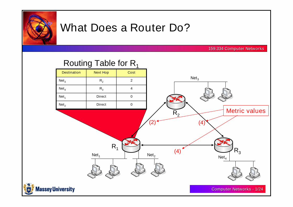
What Does a Router Do?
0DirectNet2
0DirectNet1
4R3Net4
2R2Net3
CostNext HopDestination
R1
R2
R3Net1 Net2
Net3
Net4
Routing Table for R1
(4)
(2) (4)
Metric values

Computer NetworksComputer Networks -- 1/1/2525
159.334 Computer Networks159.334 Computer Networks
Why is Traffic Engineering needed?
1
3
2(20, 4)
(0, 4)(0, 2)
distance metriclink load
each link capacity = 15
20 units of trafficfrom node 1 tonode 2
CONGESTION!!!
1 → 2 : 41 → 3 → 2 : 2+4=6
The Shortest Path Routing Problem
Computer NetworksComputer Networks -- 1/1/2626
159.334 Computer Networks159.334 Computer Networks
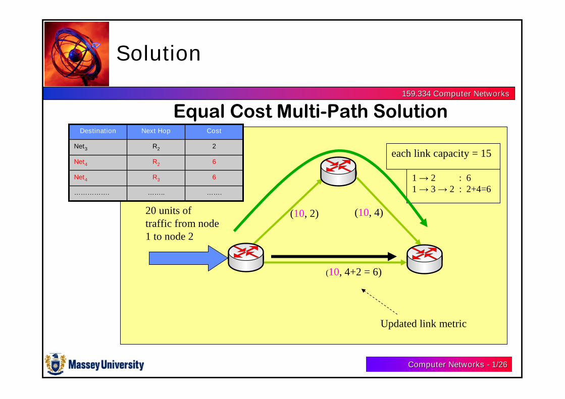
Solution
1
3
2
(10, 4+2 = 6)
(10, 4)(10, 2)
Updated link metric
each link capacity = 15
20 units oftraffic from node1 to node 2
1 → 2 : 61 → 3 → 2 : 2+4=6
Equal Cost Multi-Path Solution
…….……..…………….
6R3Net4
6R2Net4
2R2Net3
CostNext HopDestination
Computer NetworksComputer Networks -- 1/1/2727
159.334 Computer Networks159.334 Computer Networks
Weight Setting using LinearProgramming (LP)
Is a Novel TechniqueCan use existing LP packages (eg CPLEX)
Thus
More robust - won’t break down
It is a very FAST algorithm - up to 100 times faster than searchtechniques
Still get large reduction in max. link utilisation
– AT &T Tabu search technique 15 min – 1.5 hrs ( 90 nodes)
– Our LP technique:10 seconds!!!
• Can easily use existing features to develop new methods (eg linkfailure)