Link-state routing and OSPF Olof Hagsand KTHNOC/NADA · Link-state routing and OSPF Olof Hagsand...
72
Link-state routing and OSPF Olof Hagsand KTHNOC/NADA 2D1490 p4 2007
Transcript of Link-state routing and OSPF Olof Hagsand KTHNOC/NADA · Link-state routing and OSPF Olof Hagsand...
Link-state routing and OSPF
Olof Hagsand KTHNOC/NADA
2D1490 p4 2007
Literature
RFC 2328:● Section 2 except 2.1.1● Section 3 (areas), but only last two paragraphs of 3.5
Link-state routing
● Each router spreads information about its links to its neighbours.
● This information is flooded to every router in the routing domain so that every router has knowledge of the entire network topology.
● Using Dijkstra's algorithm, the shortest path to each prefix in the network is calculated
Comparison with Distance-vector
● Link-state uses a distributed database model● Distance-vector uses a distributed processing model● Link-state pros:
– More functionality due to distribution of original data, no dependency on intermediate routers
● Easier to troubleshoot
– Fast convergence: when the network changes, new routes are computed quickly
– Less bandwidth consuming
● Distance-vector pros:– Less complex – easier to implement and administrate
– Needs less memory
Comparison with IS-IS● Both are link-state protocols● IS-IS has a longer history from Digital via OSI● OSPF is newer and developed in IETF● Area difference
– OSPF defines area boundaries between interfaces
– IS-IS defines area boundaries between nodes
– IS-IS areas leads to simpler configuration
● Protocol dependency
– IS-IS can run many protocols (IPv6, CLNP)
– OSPF only IPv4, ( OSPFv3 supports IPv6)
● OSPF is implemented on more platforms and more deployed● IS-IS often popular among backbone networks
Original OSPF requirements
● A more descriptive routing metric– Link metric: 1-65535
● Equal-cost multipath– Multiple best paths: load balance
● Routing hierarchy– Two-level routing scheme: areas
● Separate internal and external routes
– External routes● Security
– Cryptographic authentication
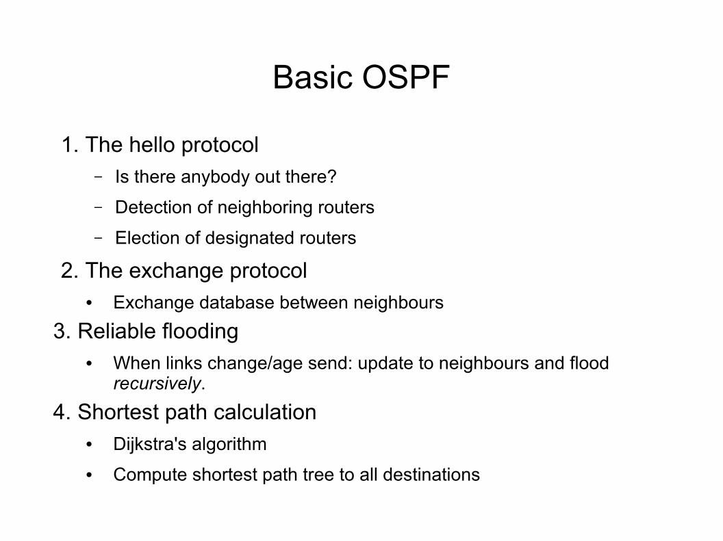
Basic OSPF
1. The hello protocol– Is there anybody out there?
– Detection of neighboring routers
– Election of designated routers
2. The exchange protocol
• Exchange database between neighbours
3. Reliable flooding
• When links change/age send: update to neighbours and flood recursively.
4. Shortest path calculation
• Dijkstra's algorithm
• Compute shortest path tree to all destinations
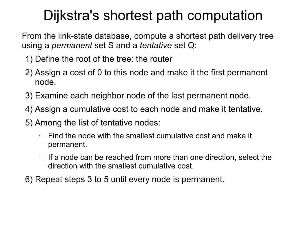
Dijkstra's shortest path computationFrom the link-state database, compute a shortest path delivery tree using a permanent set S and a tentative set Q:
1) Define the root of the tree: the router
2) Assign a cost of 0 to this node and make it the first permanent node.
3) Examine each neighbor node of the last permanent node.
4) Assign a cumulative cost to each node and make it tentative.
5) Among the list of tentative nodes:• Find the node with the smallest cumulative cost and make it
permanent.
• If a node can be reached from more than one direction, select the direction with the smallest cumulative cost.
6) Repeat steps 3 to 5 until every node is permanent.
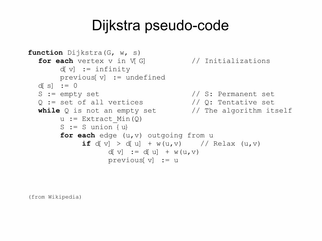
Dijkstra pseudo-code
function Dijkstra(G, w, s)for each vertex v in V[G] // Initializations d[v] := infinity previous[v] := undefinedd[s] := 0S := empty set // S: Permanent setQ := set of all vertices // Q: Tentative setwhile Q is not an empty set // The algorithm itself u := Extract_Min(Q) S := S union {u} for each edge (u,v) outgoing from u if d[v] > d[u] + w(u,v) // Relax (u,v) d[v] := d[u] + w(u,v) previous[v] := u
(from Wikipedia)
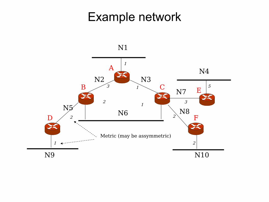
Example network
N1
N6
N4
N9 N10
N2 N3
N5
N7
N8
A
B C
D
E
F
1
13
21
2
1 2
2
3
5
Metric (may be assymmetric)
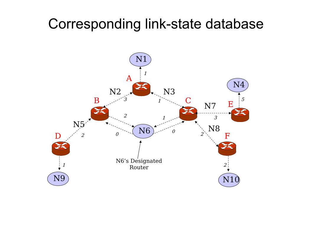
Corresponding link-state database
N2 N3
N5
N7
N8
A
B C
D
E
F
N1
N6’s DesignatedRouter
N6
N9
N4
N10
1
13
2 1
2
1 2
2
3
5
0 0
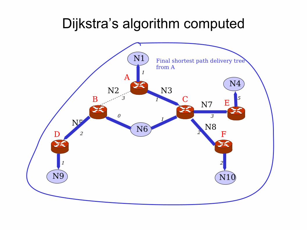
Dijkstra’s algorithm computed
N2 N3
N5
N7
N8
A
B C
D
E
F
N1
N6
N9
N4
N10
1
13
01
2
1 2
2
3
5
Final shortest path delivery tree from A
OSPF Encapsulation
● OSPF runs directly on IP● Needs its own reliable protocol
– The flooding protocol
● No port numbers– Need to run as root – raw sockets
● No checksum– Computes its own checksum or digest
● Since it runs on IP (IS-IS runs on the link-level)– OSPF messages can be routed – tunneled or routed by some other
protocol
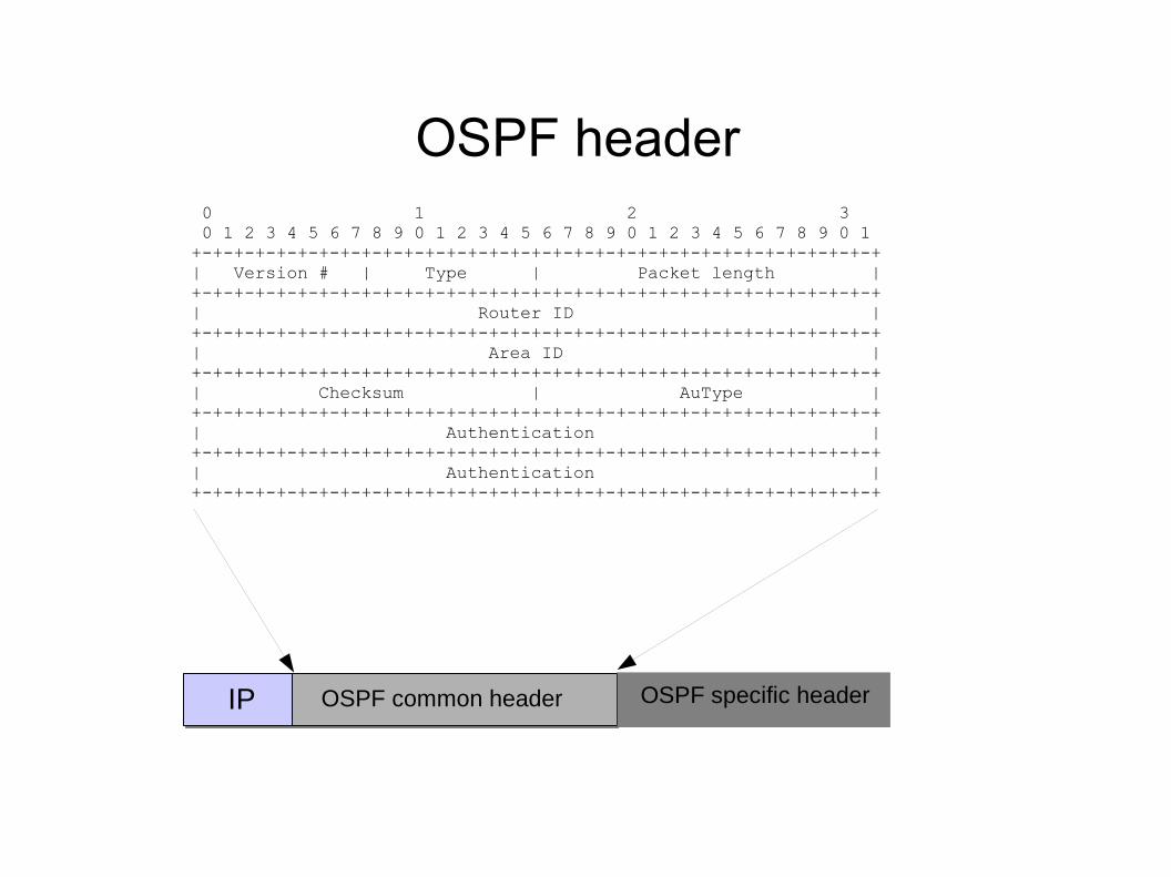
OSPF header 0 1 2 3 0 1 2 3 4 5 6 7 8 9 0 1 2 3 4 5 6 7 8 9 0 1 2 3 4 5 6 7 8 9 0 1 +-+-+-+-+-+-+-+-+-+-+-+-+-+-+-+-+-+-+-+-+-+-+-+-+-+-+-+-+-+-+-+-+ | Version # | Type | Packet length | +-+-+-+-+-+-+-+-+-+-+-+-+-+-+-+-+-+-+-+-+-+-+-+-+-+-+-+-+-+-+-+-+ | Router ID | +-+-+-+-+-+-+-+-+-+-+-+-+-+-+-+-+-+-+-+-+-+-+-+-+-+-+-+-+-+-+-+-+ | Area ID | +-+-+-+-+-+-+-+-+-+-+-+-+-+-+-+-+-+-+-+-+-+-+-+-+-+-+-+-+-+-+-+-+ | Checksum | AuType | +-+-+-+-+-+-+-+-+-+-+-+-+-+-+-+-+-+-+-+-+-+-+-+-+-+-+-+-+-+-+-+-+ | Authentication | +-+-+-+-+-+-+-+-+-+-+-+-+-+-+-+-+-+-+-+-+-+-+-+-+-+-+-+-+-+-+-+-+ | Authentication | +-+-+-+-+-+-+-+-+-+-+-+-+-+-+-+-+-+-+-+-+-+-+-+-+-+-+-+-+-+-+-+-+
IP OSPF common header OSPF specific header
OSPF common header
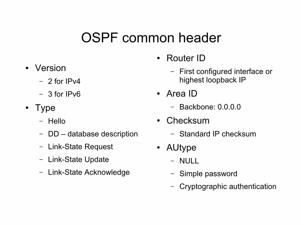
● Version– 2 for IPv4
– 3 for IPv6
● Type– Hello
– DD – database description
– Link-State Request
– Link-State Update
– Link-State Acknowledge
● Router ID– First configured interface or
highest loopback IP
● Area ID– Backbone: 0.0.0.0
● Checksum– Standard IP checksum
● AUtype– NULL
– Simple password
– Cryptographic authentication
Cryptographic authentication
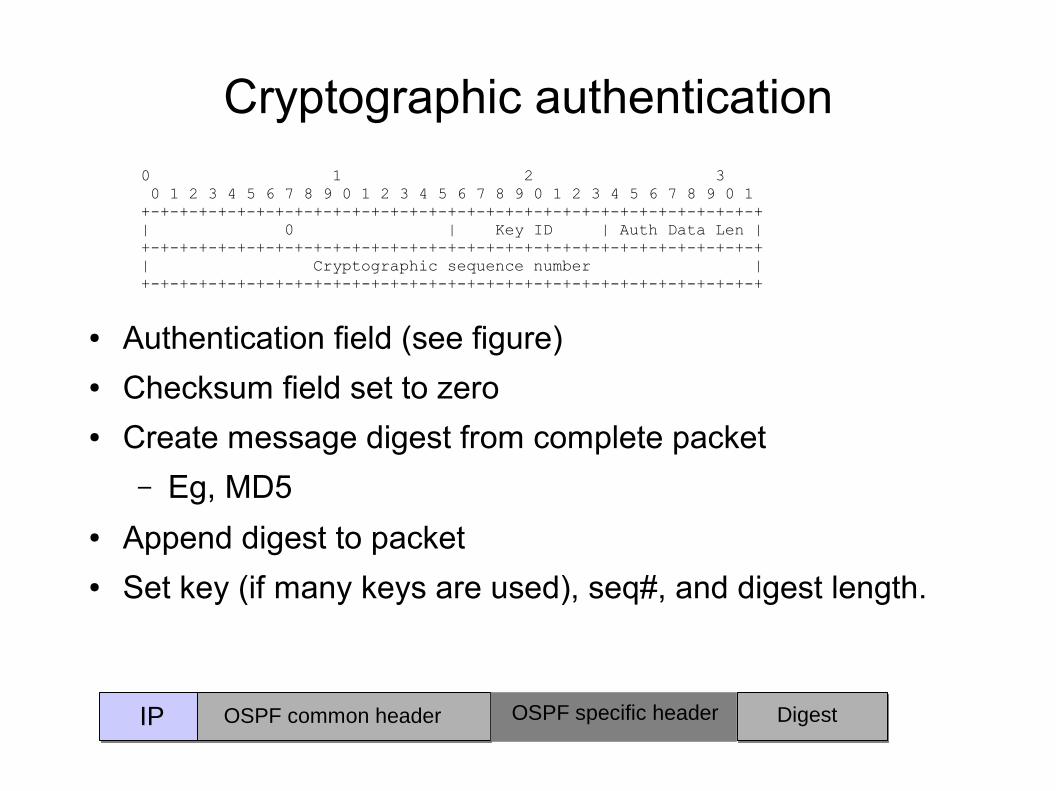
● Authentication field (see figure)● Checksum field set to zero● Create message digest from complete packet
– Eg, MD5● Append digest to packet● Set key (if many keys are used), seq#, and digest length.
0 1 2 3 0 1 2 3 4 5 6 7 8 9 0 1 2 3 4 5 6 7 8 9 0 1 2 3 4 5 6 7 8 9 0 1 +-+-+-+-+-+-+-+-+-+-+-+-+-+-+-+-+-+-+-+-+-+-+-+-+-+-+-+-+-+-+-+-+ | 0 | Key ID | Auth Data Len | +-+-+-+-+-+-+-+-+-+-+-+-+-+-+-+-+-+-+-+-+-+-+-+-+-+-+-+-+-+-+-+-+ | Cryptographic sequence number | +-+-+-+-+-+-+-+-+-+-+-+-+-+-+-+-+-+-+-+-+-+-+-+-+-+-+-+-+-+-+-+-+
IP OSPF common header OSPF specific header Digest
OSPF Adjacency
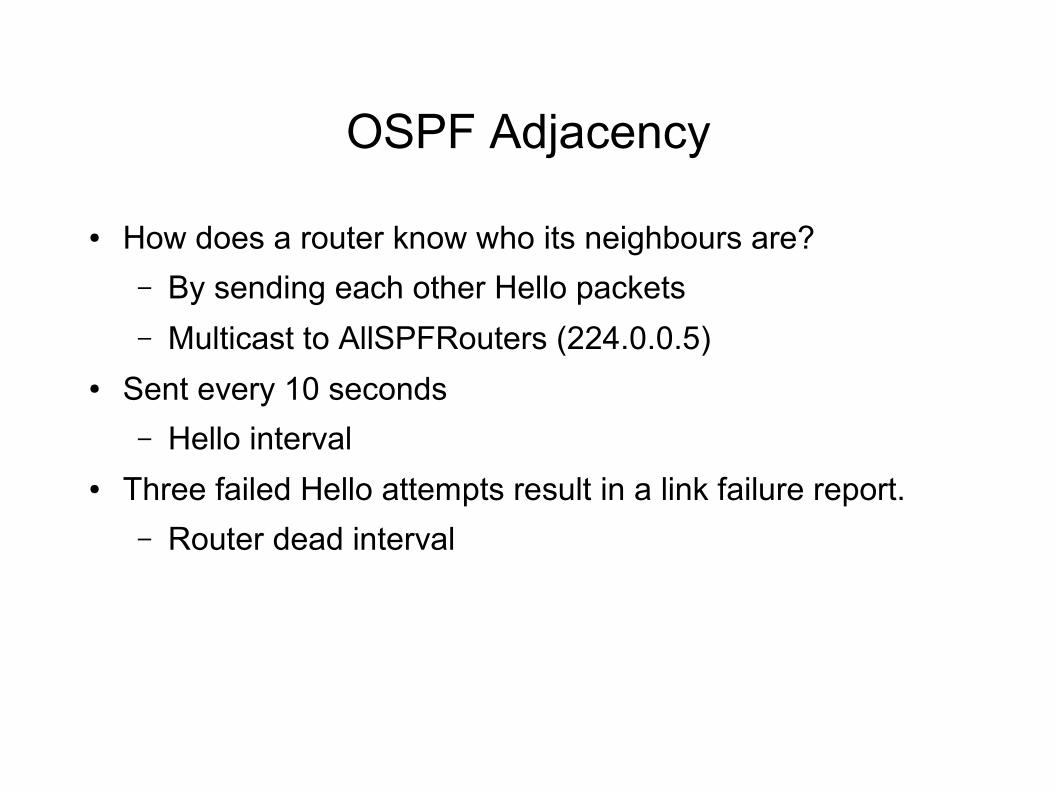
● How does a router know who its neighbours are?
– By sending each other Hello packets
– Multicast to AllSPFRouters (224.0.0.5)● Sent every 10 seconds
– Hello interval● Three failed Hello attempts result in a link failure report.
– Router dead interval
The Hello packet
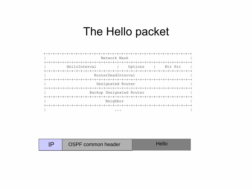
+-+-+-+-+-+-+-+-+-+-+-+-+-+-+-+-+-+-+-+-+-+-+-+-+-+-+-+-+-+-+-+-+ | Network Mask | +-+-+-+-+-+-+-+-+-+-+-+-+-+-+-+-+-+-+-+-+-+-+-+-+-+-+-+-+-+-+-+-+ | HelloInterval | Options | Rtr Pri | +-+-+-+-+-+-+-+-+-+-+-+-+-+-+-+-+-+-+-+-+-+-+-+-+-+-+-+-+-+-+-+-+ | RouterDeadInterval | +-+-+-+-+-+-+-+-+-+-+-+-+-+-+-+-+-+-+-+-+-+-+-+-+-+-+-+-+-+-+-+-+ | Designated Router | +-+-+-+-+-+-+-+-+-+-+-+-+-+-+-+-+-+-+-+-+-+-+-+-+-+-+-+-+-+-+-+-+ | Backup Designated Router | +-+-+-+-+-+-+-+-+-+-+-+-+-+-+-+-+-+-+-+-+-+-+-+-+-+-+-+-+-+-+-+-+ | Neighbor | +-+-+-+-+-+-+-+-+-+-+-+-+-+-+-+-+-+-+-+-+-+-+-+-+-+-+-+-+-+-+-+-+ | ... |
IP OSPF common header Hello
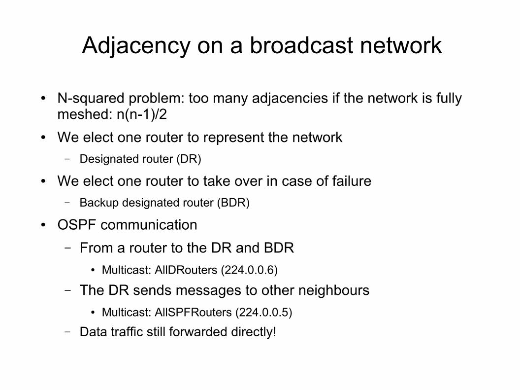
Adjacency on a broadcast network
● N-squared problem: too many adjacencies if the network is fully meshed: n(n-1)/2
● We elect one router to represent the network– Designated router (DR)
● We elect one router to take over in case of failure– Backup designated router (BDR)
● OSPF communication
– From a router to the DR and BDR ● Multicast: AllDRouters (224.0.0.6)
– The DR sends messages to other neighbours● Multicast: AllSPFRouters (224.0.0.5)
– Data traffic still forwarded directly!
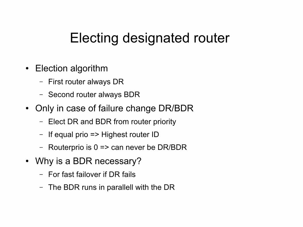
Electing designated router
● Election algorithm– First router always DR
– Second router always BDR
● Only in case of failure change DR/BDR – Elect DR and BDR from router priority
– If equal prio => Highest router ID
– Routerprio is 0 => can never be DR/BDR
● Why is a BDR necessary?– For fast failover if DR fails
– The BDR runs in parallell with the DR
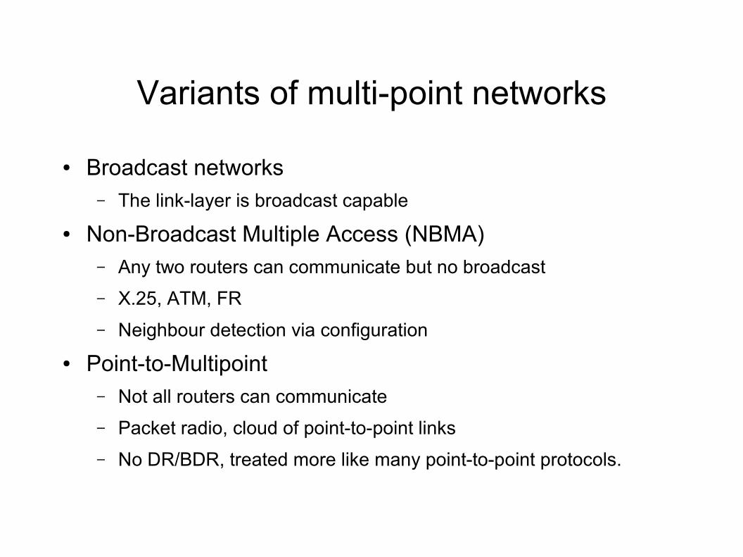
Variants of multi-point networks
● Broadcast networks– The link-layer is broadcast capable
● Non-Broadcast Multiple Access (NBMA)– Any two routers can communicate but no broadcast
– X.25, ATM, FR
– Neighbour detection via configuration
● Point-to-Multipoint– Not all routers can communicate
– Packet radio, cloud of point-to-point links
– No DR/BDR, treated more like many point-to-point protocols.
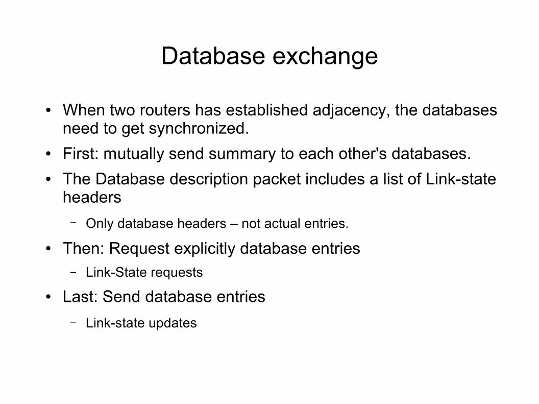
Database exchange
● When two routers has established adjacency, the databases need to get synchronized.
● First: mutually send summary to each other's databases.● The Database description packet includes a list of Link-state
headers
– Only database headers – not actual entries.
● Then: Request explicitly database entries– Link-State requests
● Last: Send database entries
– Link-state updates
Link-State Advertisements
● LSAs are the elements of the distributed database– Also called LSPs (Link-State packets)
● A router describes its environment in the form of networks that it is connected to
● Fundamental task in OSPF: – Distribute the LSAs to all nodes in a reliable way
● Then, each node can compute Dijkstra on the same database
Reliable flooding
● Every router spreads its LSAs to all its peers– That is, all information about its own links
● All routers forward the LSAs to its other peers– LSAs are acknowledged
● When a link changes, a new instance of the LSA is distributed
● Periodic updates every 30 minutes– Flood a new instance
Reliable flooding example
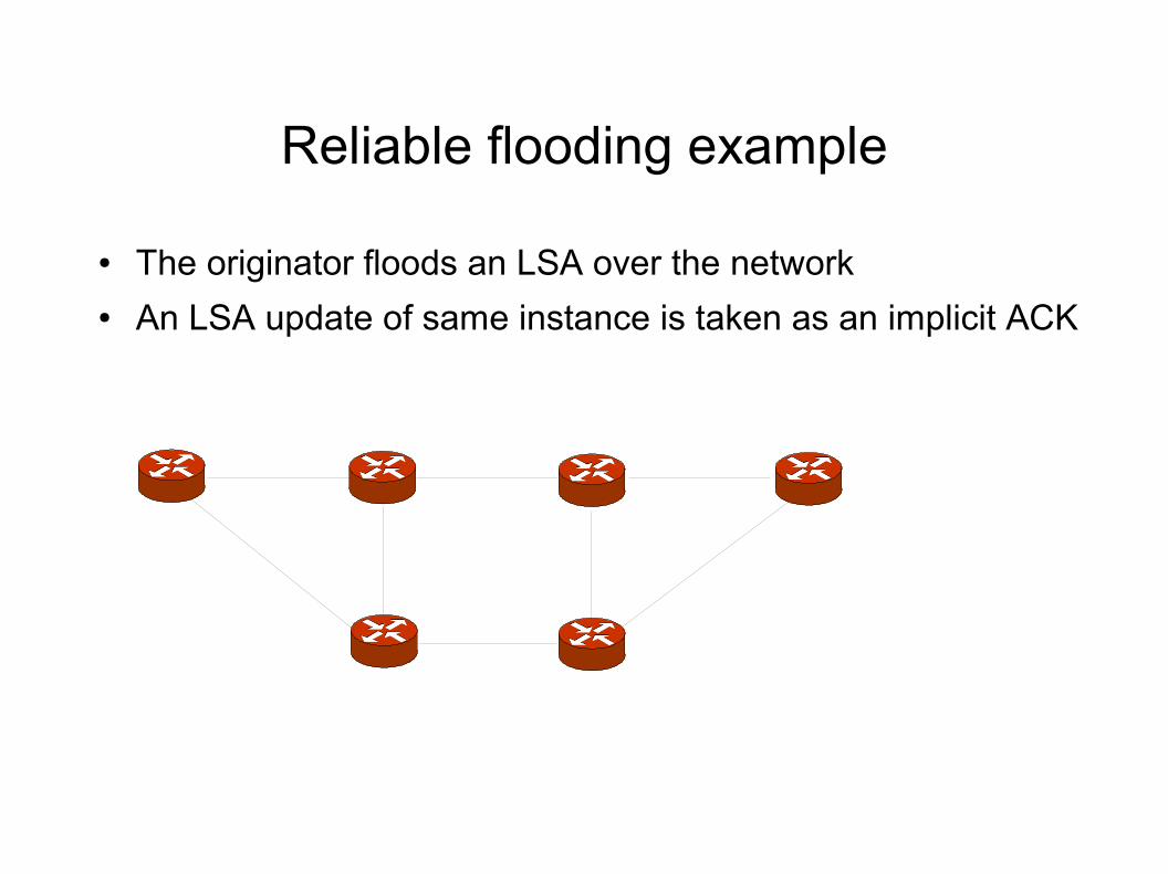
● The originator floods an LSA over the network● An LSA update of same instance is taken as an implicit ACK
Flooding in a transit network
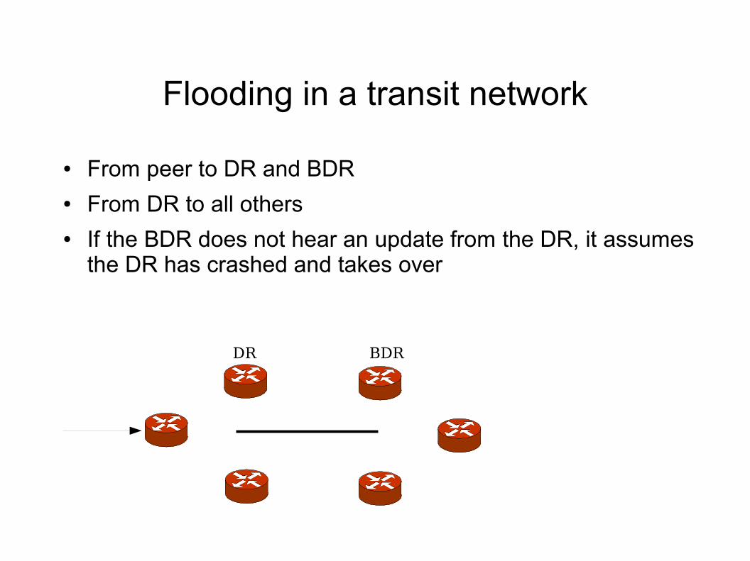
● From peer to DR and BDR● From DR to all others● If the BDR does not hear an update from the DR, it assumes
the DR has crashed and takes over
DR BDR
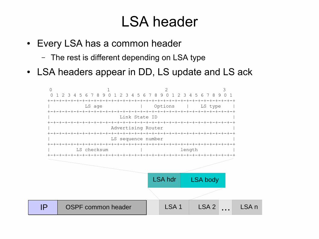
LSA header● Every LSA has a common header
– The rest is different depending on LSA type
● LSA headers appear in DD, LS update and LS ack
0 1 2 3 0 1 2 3 4 5 6 7 8 9 0 1 2 3 4 5 6 7 8 9 0 1 2 3 4 5 6 7 8 9 0 1 +-+-+-+-+-+-+-+-+-+-+-+-+-+-+-+-+-+-+-+-+-+-+-+-+-+-+-+-+-+-+-+-+ | LS age | Options | LS type | +-+-+-+-+-+-+-+-+-+-+-+-+-+-+-+-+-+-+-+-+-+-+-+-+-+-+-+-+-+-+-+-+ | Link State ID | +-+-+-+-+-+-+-+-+-+-+-+-+-+-+-+-+-+-+-+-+-+-+-+-+-+-+-+-+-+-+-+-+ | Advertising Router | +-+-+-+-+-+-+-+-+-+-+-+-+-+-+-+-+-+-+-+-+-+-+-+-+-+-+-+-+-+-+-+-+ | LS sequence number | +-+-+-+-+-+-+-+-+-+-+-+-+-+-+-+-+-+-+-+-+-+-+-+-+-+-+-+-+-+-+-+-+ | LS checksum | length | +-+-+-+-+-+-+-+-+-+-+-+-+-+-+-+-+-+-+-+-+-+-+-+-+-+-+-+-+-+-+-+-+
IP OSPF common header LSA 1 LSA 2 LSA n...
LSA hdr LSA body
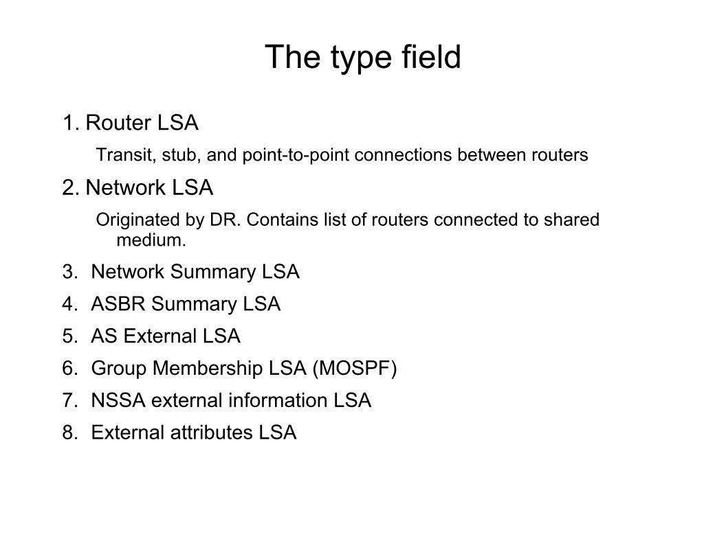
The type field
1. Router LSA
Transit, stub, and point-to-point connections between routers
2. Network LSA
Originated by DR. Contains list of routers connected to shared medium.
3. Network Summary LSA
4. ASBR Summary LSA
5. AS External LSA
6. Group Membership LSA (MOSPF)
7. NSSA external information LSA
8. External attributes LSA
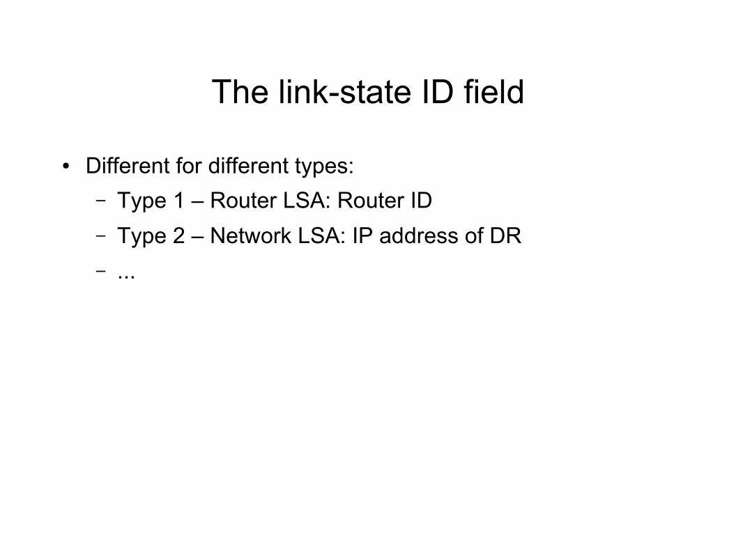
The link-state ID field
● Different for different types:
– Type 1 – Router LSA: Router ID
– Type 2 – Network LSA: IP address of DR
– ...
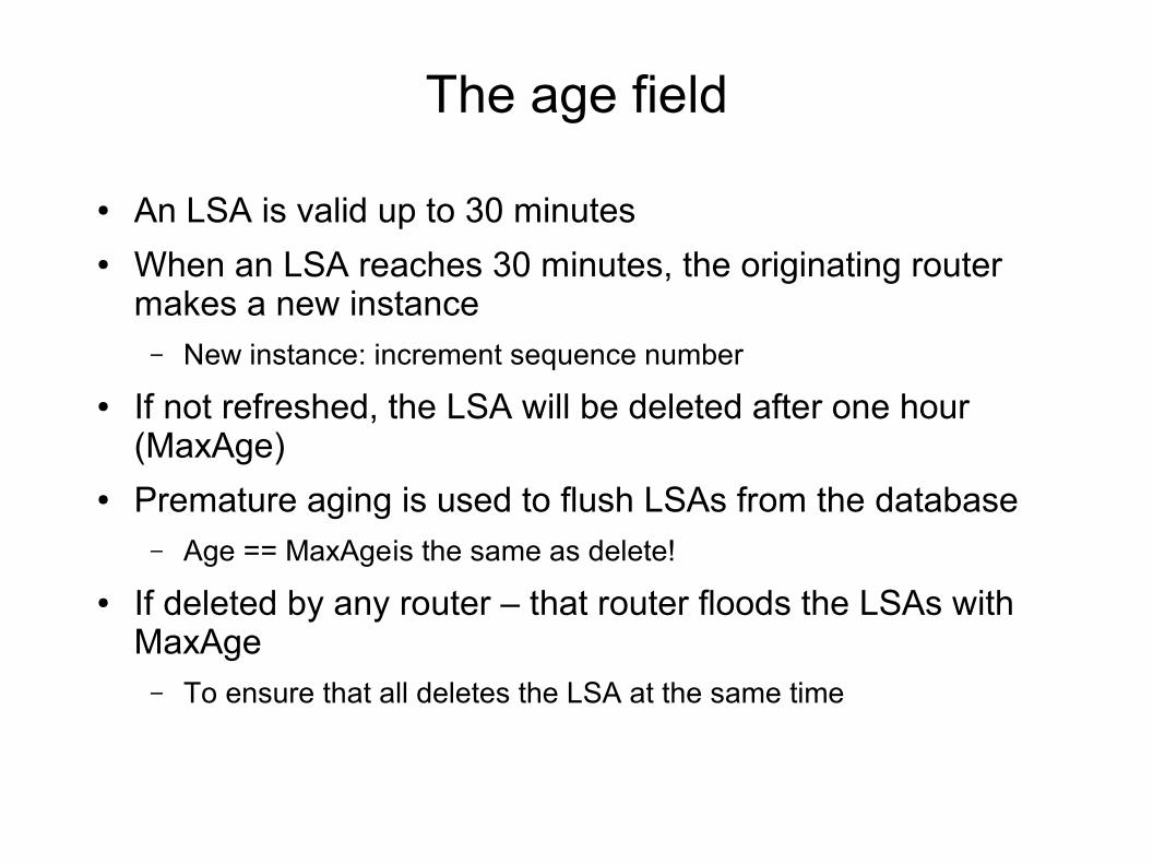
The age field
● An LSA is valid up to 30 minutes● When an LSA reaches 30 minutes, the originating router
makes a new instance – New instance: increment sequence number
● If not refreshed, the LSA will be deleted after one hour (MaxAge)
● Premature aging is used to flush LSAs from the database– Age == MaxAgeis the same as delete!
● If deleted by any router – that router floods the LSAs with MaxAge– To ensure that all deletes the LSA at the same time
Sequence number
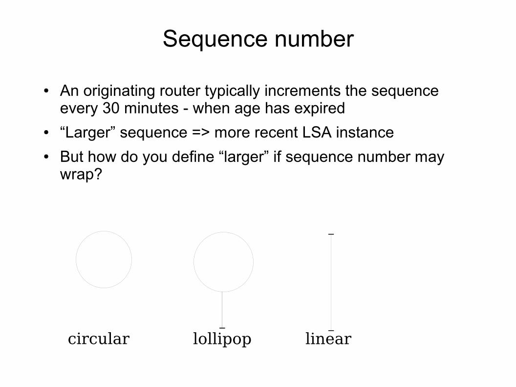
● An originating router typically increments the sequence every 30 minutes - when age has expired
● “Larger” sequence => more recent LSA instance● But how do you define “larger” if sequence number may
wrap?
circular lollipop linear
Sequence numbers
● Original ARPANET: Circular
● OSPFv1: Lollipop
● OSPFv2: Linear
● Initial sequence number: 0x80000001
● Max sequence number: 0x7fffffff
● When an LSA sequence number reaches Max, the router must delete the LSA
– By flooding of a prematured aged LSA
● And then reintroduce the LSA
● But sequence number is 32-bits, if router updates sequence # every 5 seconds it takes 600 years to wrap-around!
Metric
● The metric is dependent on LSA and is not in the common header
● The metric is a scalar 1- 65536● It can mean anything: hops, €, delay, load, ...● Metrics are asymmetric● CISCO's default metric is:
– 10^8 / <linkbw>
– Eg 10Mb eth has metric 10
– E1 (serial 2Mbps) has metric 50
● Juniper does not have this
LSA type 1: Router LSA
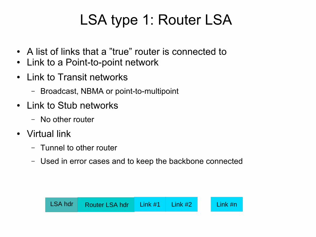
● A list of links that a ”true” router is connected to● Link to a Point-to-point network● Link to Transit networks
– Broadcast, NBMA or point-to-multipoint
● Link to Stub networks– No other router
● Virtual link– Tunnel to other router
– Used in error cases and to keep the backbone connected
LSA hdr Router LSA hdr Link #1 Link #2 Link #n
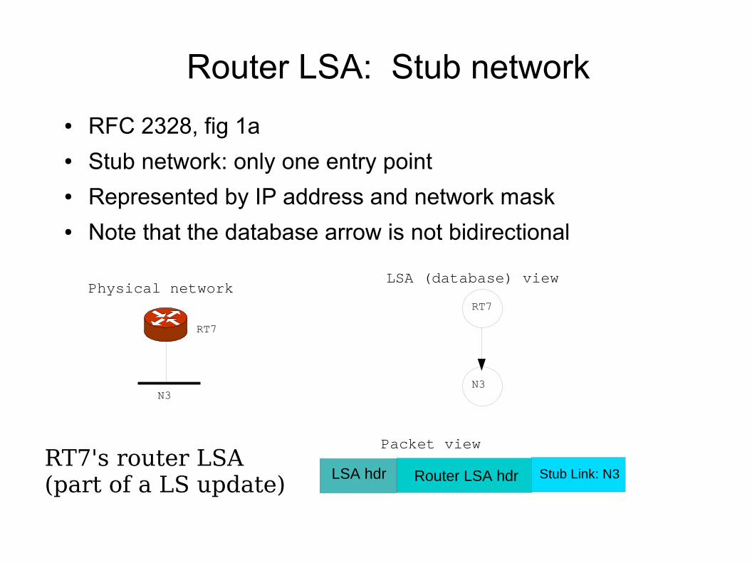
Router LSA: Stub network
● RFC 2328, fig 1a● Stub network: only one entry point● Represented by IP address and network mask● Note that the database arrow is not bidirectional
RT7
RT7
N3
LSA hdr Router LSA hdr Stub Link: N3RT7's router LSA(part of a LS update)
N3
LSA (database) viewPhysical network
Packet view
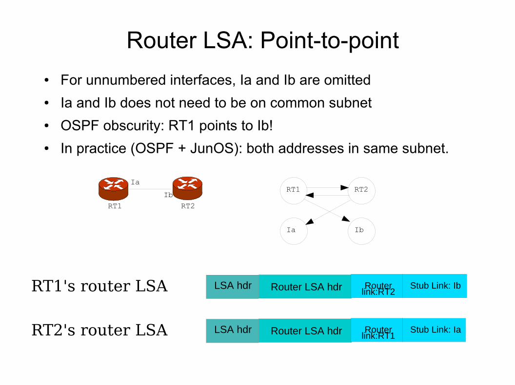
Router LSA: Point-to-point
● For unnumbered interfaces, Ia and Ib are omitted● Ia and Ib does not need to be on common subnet● OSPF obscurity: RT1 points to Ib!● In practice (OSPF + JunOS): both addresses in same subnet.
Ia
Ib
RT1 RT2
RT1 RT2
Ia Ib
LSA hdr Router LSA hdr Router link:RT2
Stub Link: IbRT1's router LSA
LSA hdr Router LSA hdr Router link:RT1
Stub Link: IaRT2's router LSA
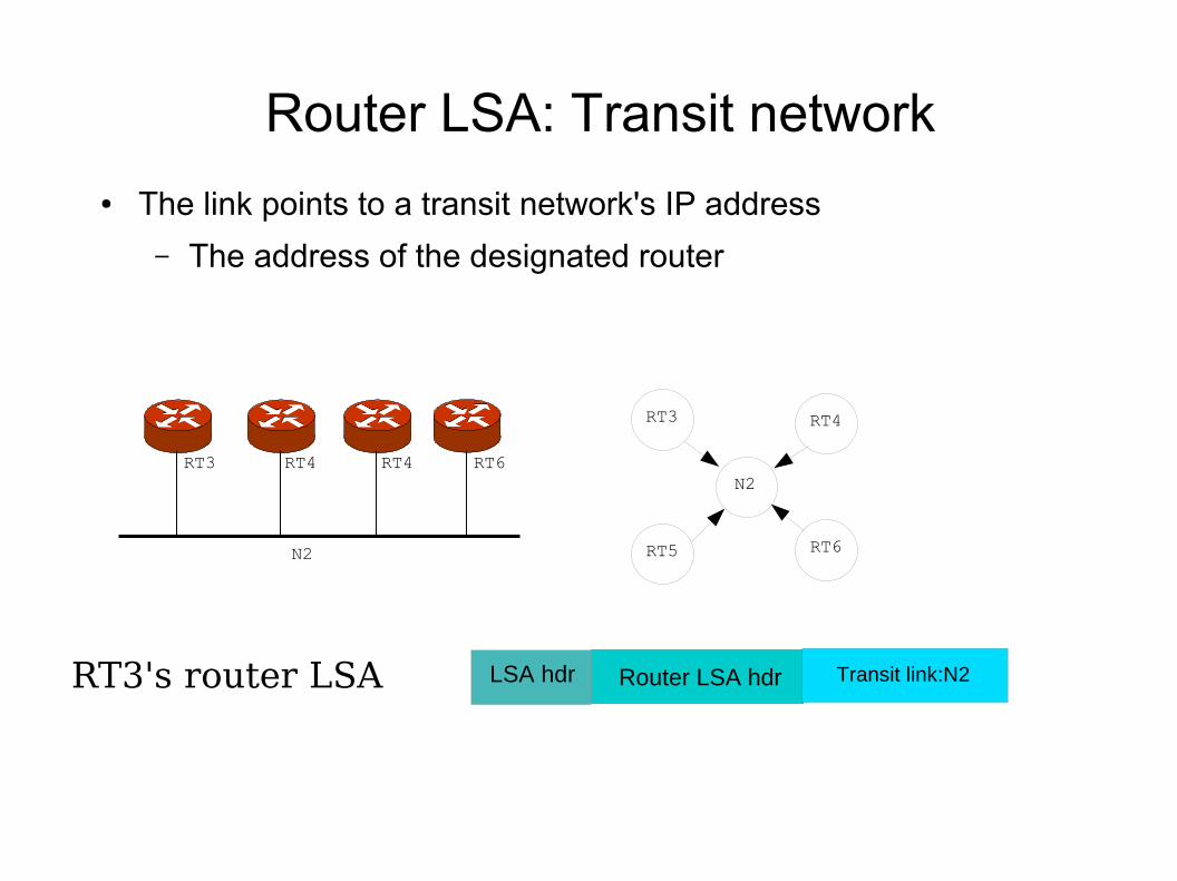
Router LSA: Transit network
● The link points to a transit network's IP address
– The address of the designated router
RT3 RT4
RT5 RT6
LSA hdr Router LSA hdr Transit link:N2RT3's router LSA
RT3 RT4 RT4 RT6
N2
N2
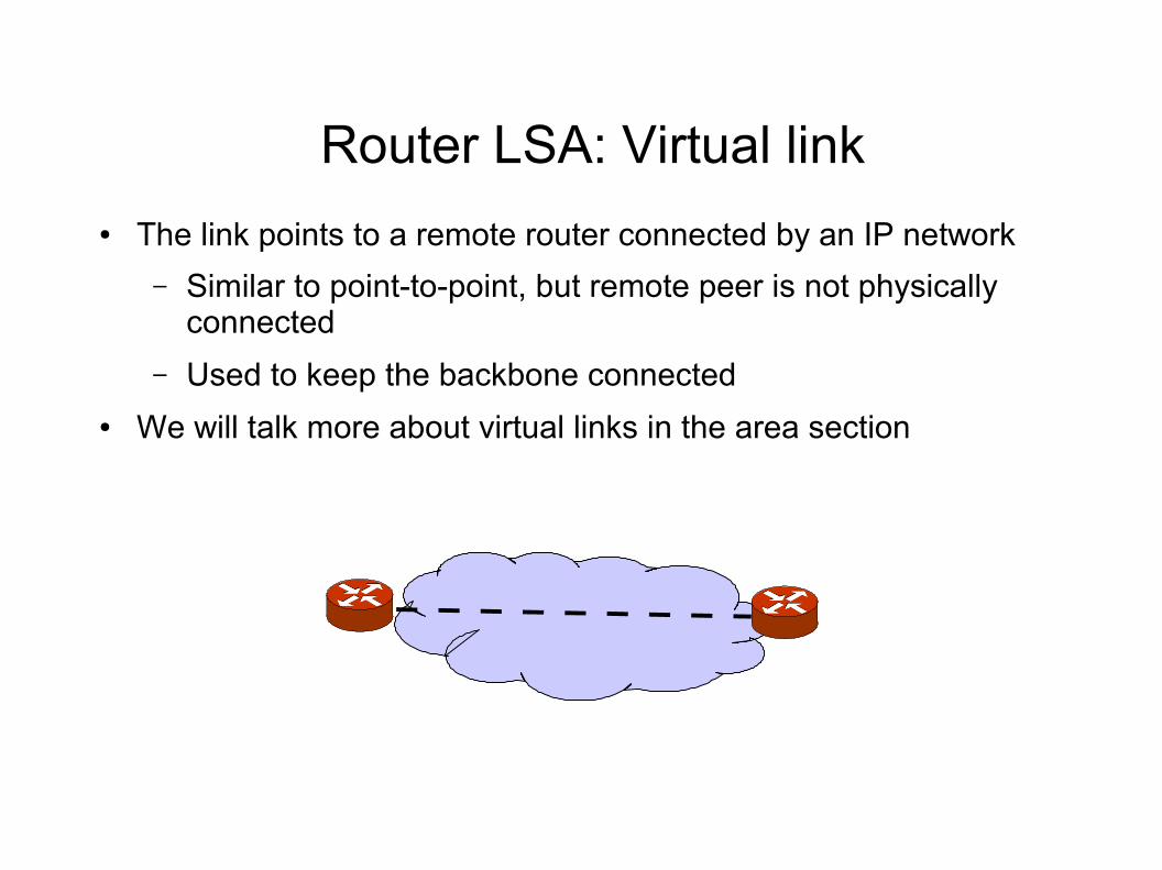
Router LSA: Virtual link
● The link points to a remote router connected by an IP network
– Similar to point-to-point, but remote peer is not physically connected
– Used to keep the backbone connected
● We will talk more about virtual links in the area section
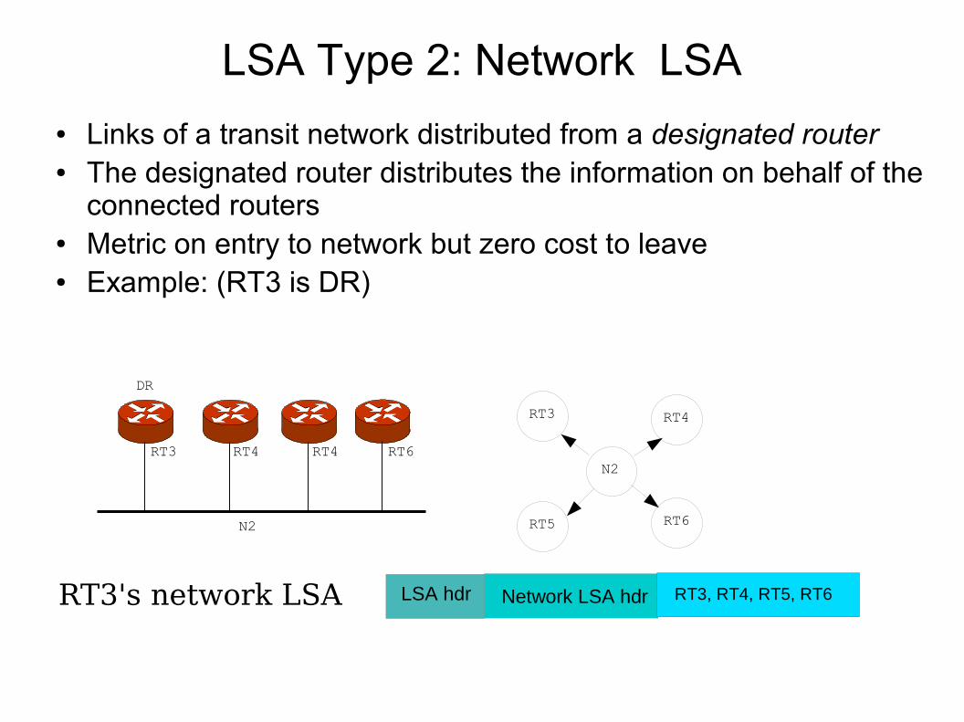
LSA Type 2: Network LSA
● Links of a transit network distributed from a designated router● The designated router distributes the information on behalf of the
connected routers● Metric on entry to network but zero cost to leave● Example: (RT3 is DR)
RT3 RT4
RT5 RT6
RT3 RT4 RT4 RT6
N2
N2
LSA hdr Network LSA hdr RT3, RT4, RT5, RT6RT3's network LSA
DR
External routes
● An external route is a prefix that OSPF has learnt from another protocol (or static route)
– Has been redistributed into OSPF
● External routes come in two flavors based on the metrics:
– External Type 1 (E1): use same metrics as internal
– External Type 2 (E2): external metric takes precedence
● If RIP routes are imported as E1, and OSPF uses hop-count metric, then OSPF and RIP can work seamlessly
● BGP routes are imported as E2, where metric is AS-path length
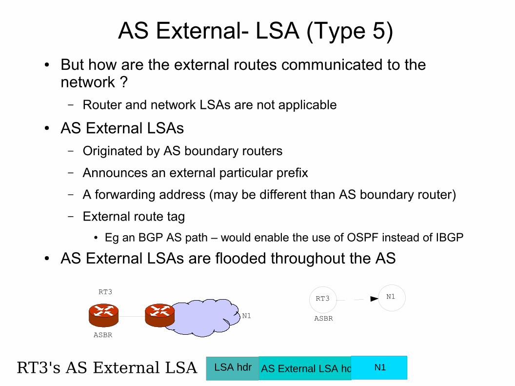
AS External- LSA (Type 5)● But how are the external routes communicated to the
network ?– Router and network LSAs are not applicable
● AS External LSAs – Originated by AS boundary routers
– Announces an external particular prefix
– A forwarding address (may be different than AS boundary router)
– External route tag
● Eg an BGP AS path – would enable the use of OSPF instead of IBGP
● AS External LSAs are flooded throughout the AS
RT3RT3
N1
N1
LSA hdr AS External LSA hdr N1RT3's AS External LSA
ASBR
ASBR
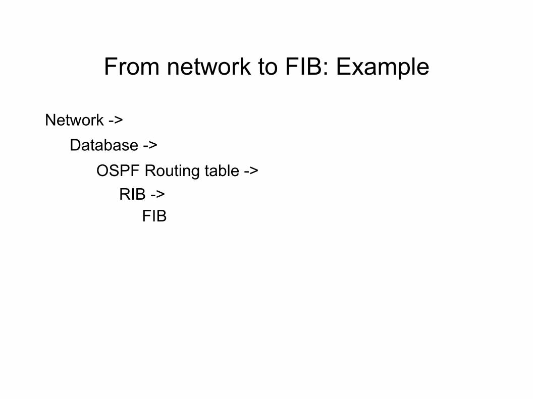
From network to FIB: Example
Network ->
Database ->
OSPF Routing table ->
RIB -> FIB
RT1N1
RT2N2
3
3
N3
1
RT4
1
RT3
N4
2
1
1RT5
RT6
8 8
8 6
N12
N13
N14
N15
8
88
6
7
RT9N11
RT12
N10
3
10
N9
1
1
H12
1
RT11
2
N8
RT10
6
Ia 7
Ib
3
N6
1
RT8
1
4
N7
RT7
6
1
9
6
62
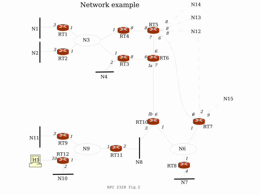
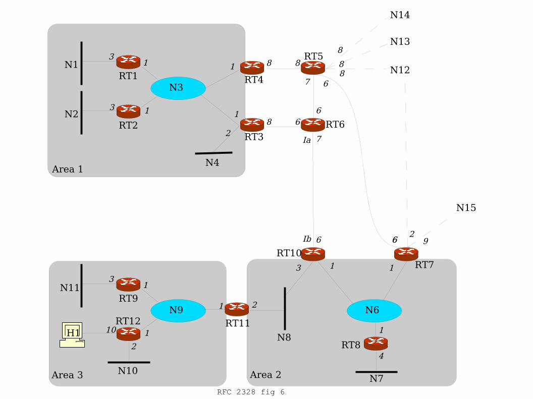
Network example
RFC 2328 fig 2
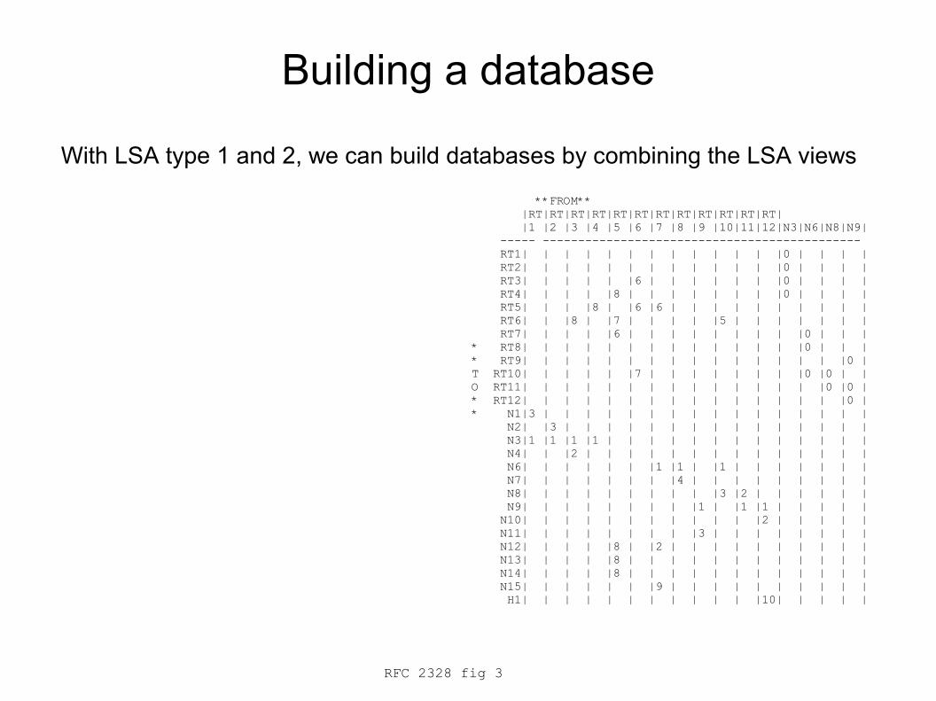
Building a database
With LSA type 1 and 2, we can build databases by combining the LSA views
**FROM** |RT|RT|RT|RT|RT|RT|RT|RT|RT|RT|RT|RT| |1 |2 |3 |4 |5 |6 |7 |8 |9 |10|11|12|N3|N6|N8|N9| ----- --------------------------------------------- RT1| | | | | | | | | | | | |0 | | | | RT2| | | | | | | | | | | | |0 | | | | RT3| | | | | |6 | | | | | | |0 | | | | RT4| | | | |8 | | | | | | | |0 | | | | RT5| | | |8 | |6 |6 | | | | | | | | | | RT6| | |8 | |7 | | | | |5 | | | | | | | RT7| | | | |6 | | | | | | | | |0 | | | * RT8| | | | | | | | | | | | | |0 | | | * RT9| | | | | | | | | | | | | | | |0 | T RT10| | | | | |7 | | | | | | | |0 |0 | | O RT11| | | | | | | | | | | | | | |0 |0 | * RT12| | | | | | | | | | | | | | | |0 | * N1|3 | | | | | | | | | | | | | | | | N2| |3 | | | | | | | | | | | | | | | N3|1 |1 |1 |1 | | | | | | | | | | | | | N4| | |2 | | | | | | | | | | | | | | N6| | | | | | |1 |1 | |1 | | | | | | | N7| | | | | | | |4 | | | | | | | | | N8| | | | | | | | | |3 |2 | | | | | | N9| | | | | | | | |1 | |1 |1 | | | | | N10| | | | | | | | | | | |2 | | | | | N11| | | | | | | | |3 | | | | | | | | N12| | | | |8 | |2 | | | | | | | | | | N13| | | | |8 | | | | | | | | | | | | N14| | | | |8 | | | | | | | | | | | | N15| | | | | | |9 | | | | | | | | | | H1| | | | | | | | | | | |10| | | | |
RFC 2328 fig 3
RT1N1
RT2N2
3
3
N31
RT4
1RT3
N4
2
1
1 RT5
RT6
8
8
8
6
N12
N13
N14
N15
8
88
6
7
RT9N11
RT12
N10
3
10
N9
1
1
H12
1RT11
2N8
RT10
5
Ib
7
Ia
3
N6
1
RT8
0
4
N7
RT7
6
1
9
6
62
0 0
0 0
5
1
00
0
00
0
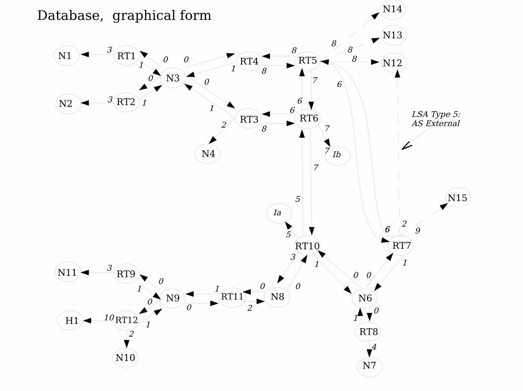
Database, graphical form
0
LSA Type 5: AS External
7
7
RT1N1
RT2N2
3
3
N3
RT4
1RT3
N4
2
RT5
RT66
N12
N13
N14
N15
8
88
6
RT9N11
RT12
N10
3
10
N9
H12
1RT11 N8
RT10
Ib
7
Ia
3
N6
1
RT8
0
4
N7
RT7
92
0
0
5
00
0
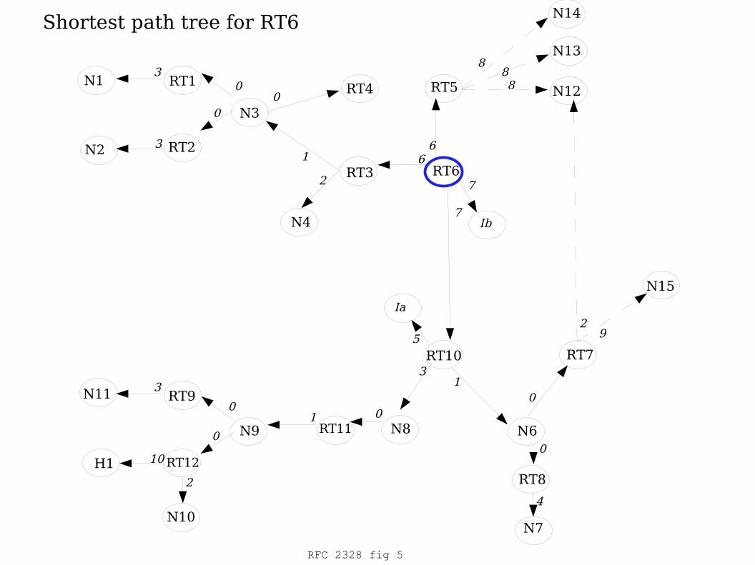
Shortest path tree for RT6
0
0
RFC 2328 fig 5
7
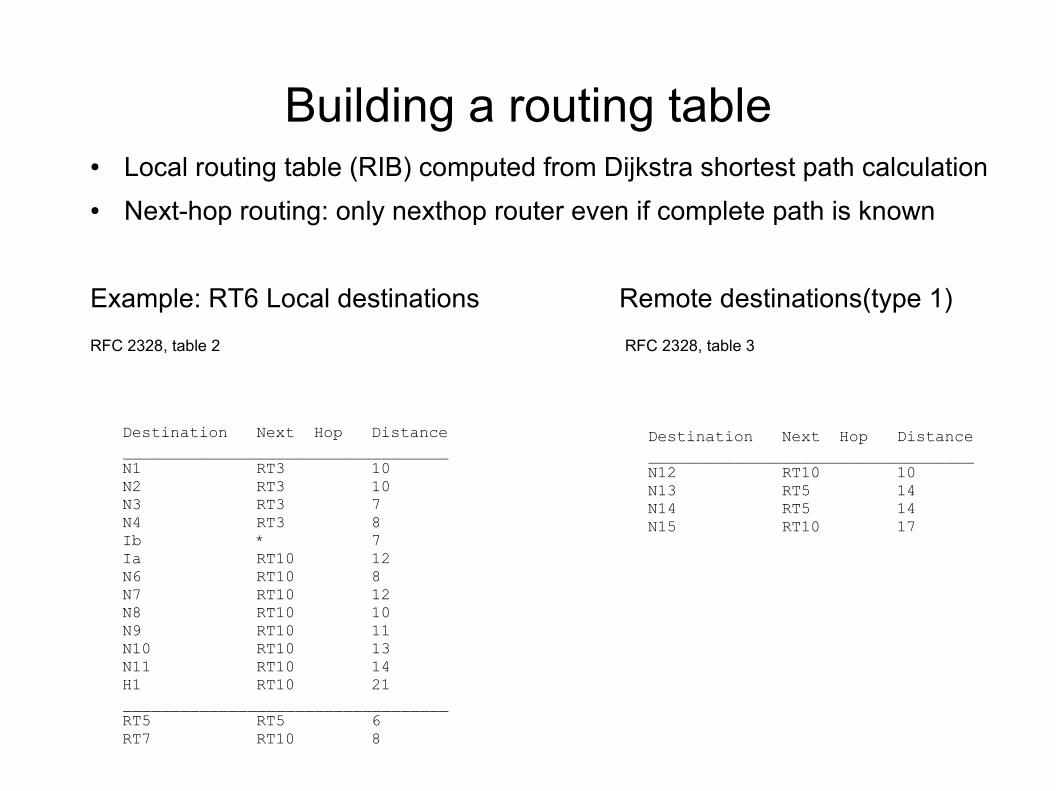
Building a routing table● Local routing table (RIB) computed from Dijkstra shortest path calculation
● Next-hop routing: only nexthop router even if complete path is known
Example: RT6 Local destinations Remote destinations(type 1)
RFC 2328, table 2 RFC 2328, table 3
Destination Next Hop Distance__________________________________N1 RT3 10N2 RT3 10N3 RT3 7N4 RT3 8Ib * 7Ia RT10 12N6 RT10 8N7 RT10 12N8 RT10 10N9 RT10 11N10 RT10 13N11 RT10 14H1 RT10 21__________________________________RT5 RT5 6RT7 RT10 8
Destination Next Hop Distance__________________________________N12 RT10 10N13 RT5 14N14 RT5 14N15 RT10 17
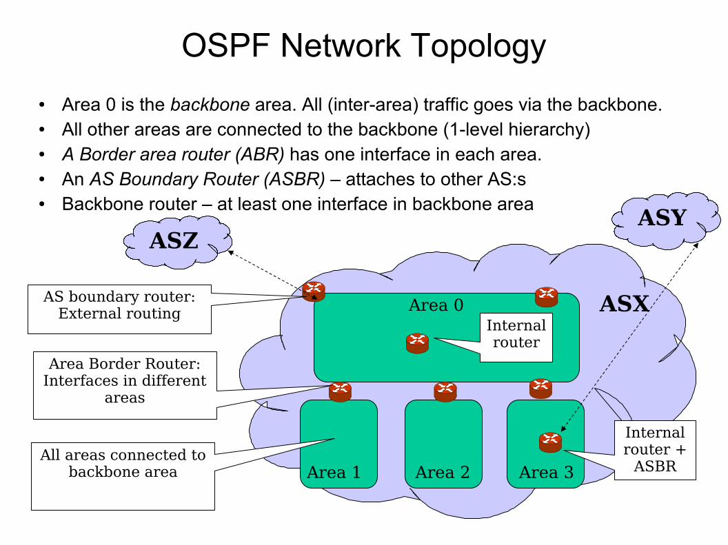
OSPF Network Topology
● Area 0 is the backbone area. All (inter-area) traffic goes via the backbone.● All other areas are connected to the backbone (1-level hierarchy)● A Border area router (ABR) has one interface in each area.● An AS Boundary Router (ASBR) – attaches to other AS:s● Backbone router – at least one interface in backbone area
AS2 ASXArea 0
Area 1 Area 2 Area 3
Area Border Router:Interfaces in different
areas
AS boundary router:External routing
All areas connected tobackbone area
Internal router +
ASBR
Internal router
ASYASZ
OSPF Areas● Divides the OSPF domain into smaller zones
– Smaller link-state database in each zone
– Also decreases signaling traffic
● Routers have limits on processing power and memory
– Router CPUs are typically much slower than PCs
● CISCO used to recommend ~80 routers as a limit in a single area● You need a large network to benefit from areas
– Typical large companies
● Example: KTHLAN using OSPF with 15-20 routers used to have areas – but now only uses area 0.
● However, areas are less used today. More often divide your internal network into BGP confederations, for example
Smaller database● Using areas makes the database smaller
– That is, fewer and more compact LSAs
● The destinations inside the area is still fully described by type-1 router and type-2 network LSAs– Full Dijkstra algorithm
● But destinations outside the area are summarized● Only the (cumulative) metric and prefix necessary
– Not full link state
● This leads to a smaller database and less processing to compute shortest path
Route summarization
● When the details of an area has been hidden it makes sense to aggregate the prefixes
● Typically, all networks within an area, can be summarized into one LSA– Routes can also be summarized at redistribution to/from
another protocol
● The metric uses the max of all summarized metrics● In the example, area 2's routes are summarized:
– N9-N11, H1
– With max cost 11 (to H1)
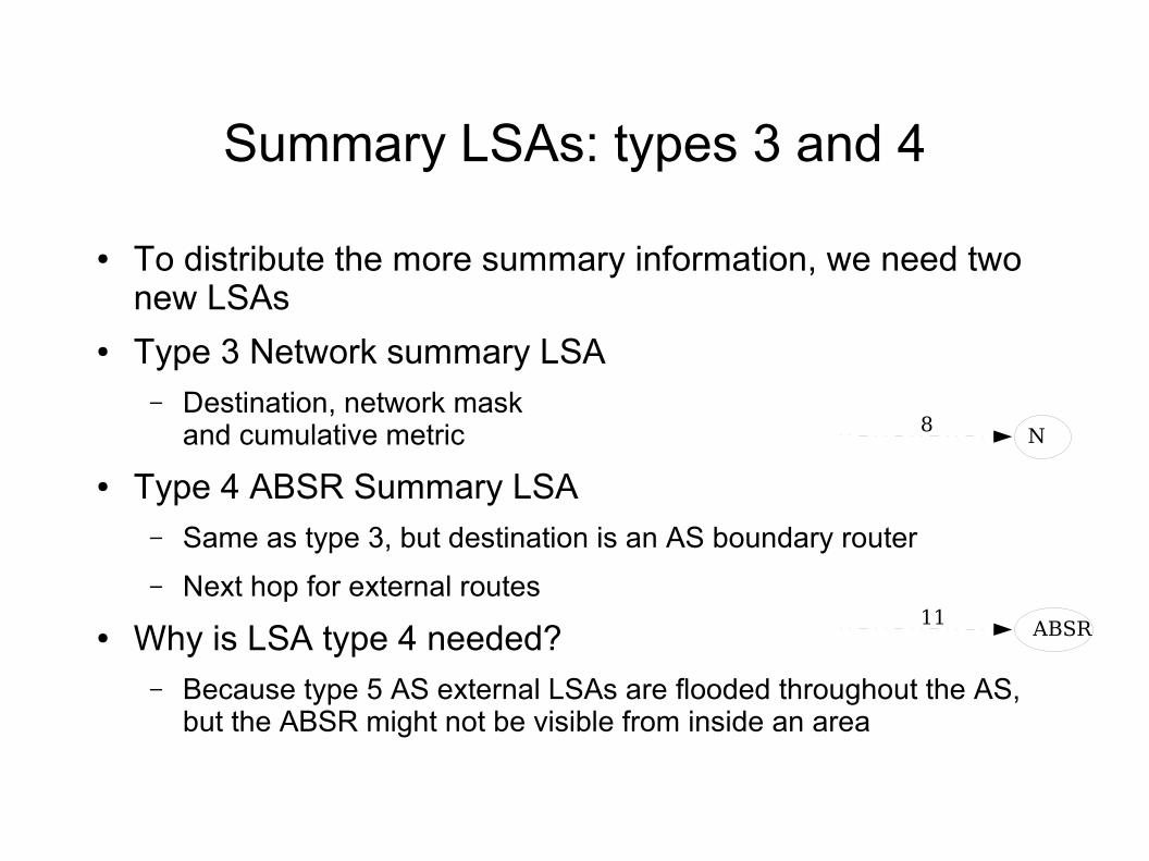
Summary LSAs: types 3 and 4
● To distribute the more summary information, we need two new LSAs
● Type 3 Network summary LSA– Destination, network mask
and cumulative metric
● Type 4 ABSR Summary LSA– Same as type 3, but destination is an AS boundary router
– Next hop for external routes
● Why is LSA type 4 needed?– Because type 5 AS external LSAs are flooded throughout the AS,
but the ABSR might not be visible from inside an area
N8
ABSR11
Area 2
RT1N1
RT2N2
3
3
N3
1
RT4
1
RT3
N4
2
1
1RT5
RT6
8 8
8 6
N12
N13
N14
N15
8
88
6
7
RT9N11
RT12
N10
3
10
N9
1
1
H12
1
RT11
2
N8
RT10
6
Ia 7
Ib
3
N6
1
RT8
1
4
N7
RT7
6
1
9
6
62
Area 1
Area 3
RFC 2328 fig 6
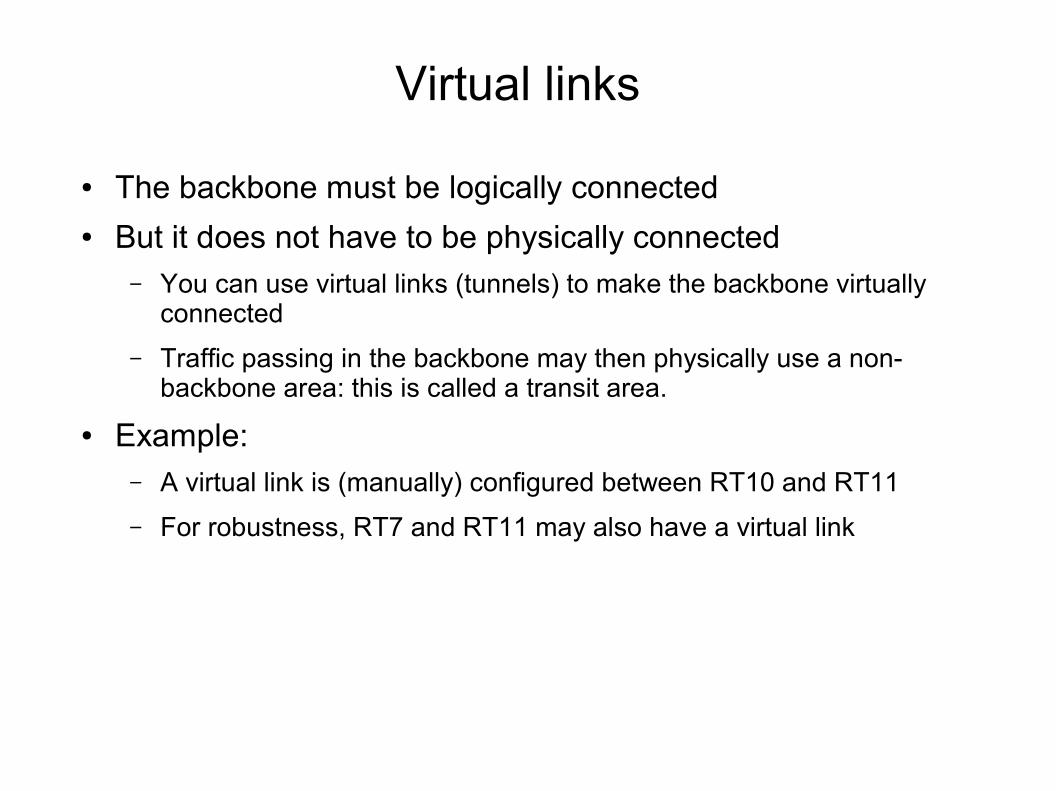
Virtual links
● The backbone must be logically connected● But it does not have to be physically connected
– You can use virtual links (tunnels) to make the backbone virtually connected
– Traffic passing in the backbone may then physically use a non-backbone area: this is called a transit area.
● Example:– A virtual link is (manually) configured between RT10 and RT11
– For robustness, RT7 and RT11 may also have a virtual link
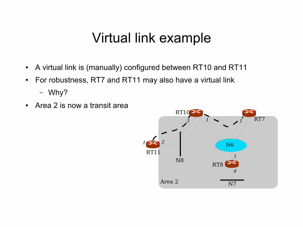
Virtual link example
● A virtual link is (manually) configured between RT10 and RT11
● For robustness, RT7 and RT11 may also have a virtual link
– Why?
● Area 2 is now a transit area
Area 2
1
RT11
2
N8
RT10
3
N6
1
RT8
1
4
N7
RT71
Example● RFC 2328, section 3● Using Area 0 and 1 as examples shows● Note 1: The Area Border Routers (RT3 and RT4) injects
summaries both – Into Area 1 from the backbone and other areas
– Into area 0 (backbone) from area 1
● Note 2: The external routes are flooded through all areas● Note 3: Area 1 has two points of exits
– Internal routers can make intelligent decisions, and load balance between exit points
– Example: RT1 uses RT4 to N6, RT3 to N10, and load balance to N8!
N8
N6N7
Area 1
RT4
RT3
RT5
RT6
8
8
8
6
N12
N13
N14
N15
8
88
6
7
RT11
RT10
5
Ib
7
Ia
3RT7
6 9
6
62
N3
N2
N1
N4
5
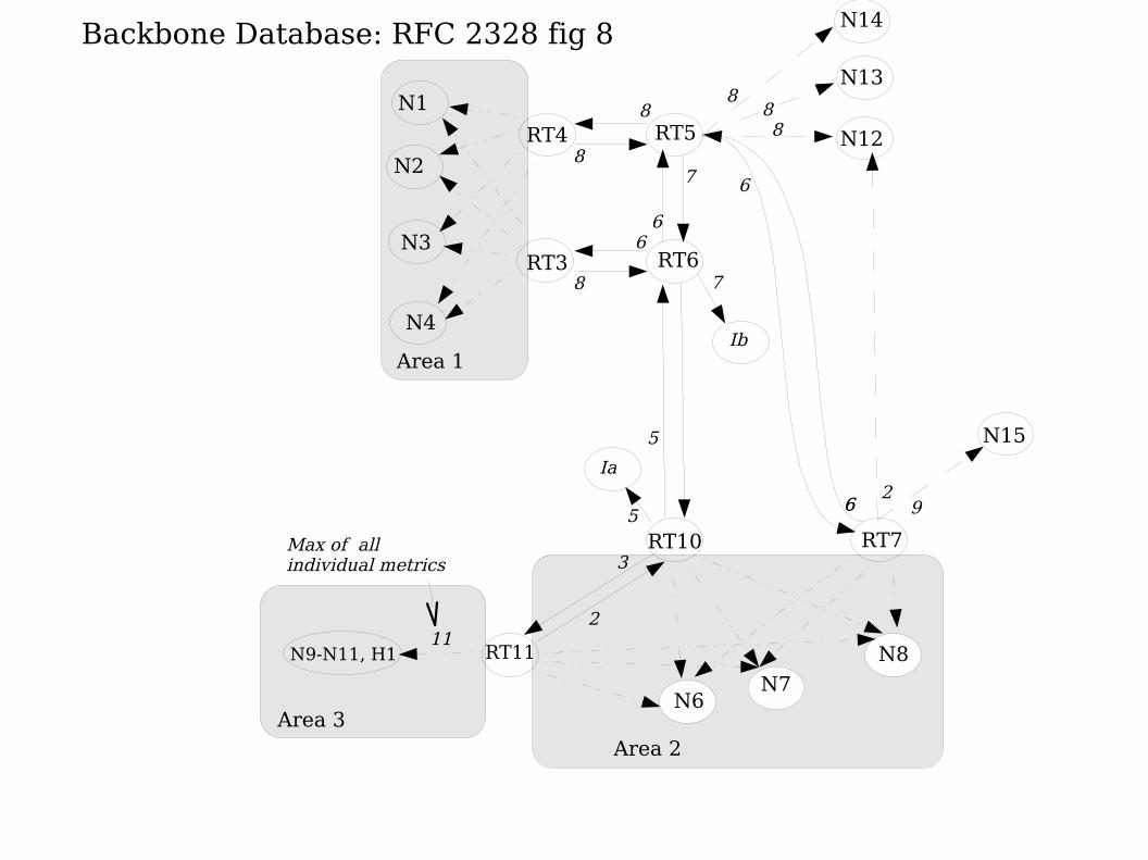
Backbone Database: RFC 2328 fig 8
N9-N11, H1
Area 3
2
Area 2
11
Max of all individual metrics
RT1N1
RT2N2
3
3
N31
RT4
1RT3
N4
2
1
1
RT5 N12
N13
N14
N15
8
88
9
2
N9-N11, H1
N8
N6
Ib
Ia
0 0
0 0
N7
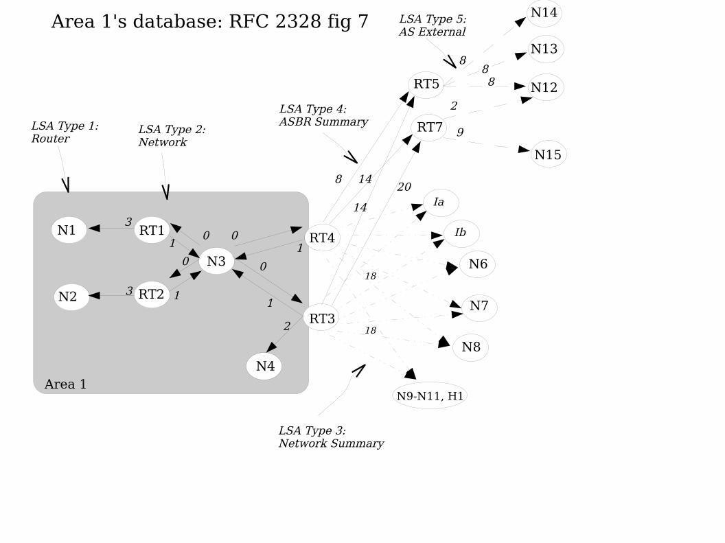
Area 1's database: RFC 2328 fig 7
RT7
8 14
14
20
LSA Type 5: AS External
LSA Type 3: Network Summary
LSA Type 4: ASBR SummaryLSA Type 1:
RouterLSA Type 2: Network
Area 1
18
18
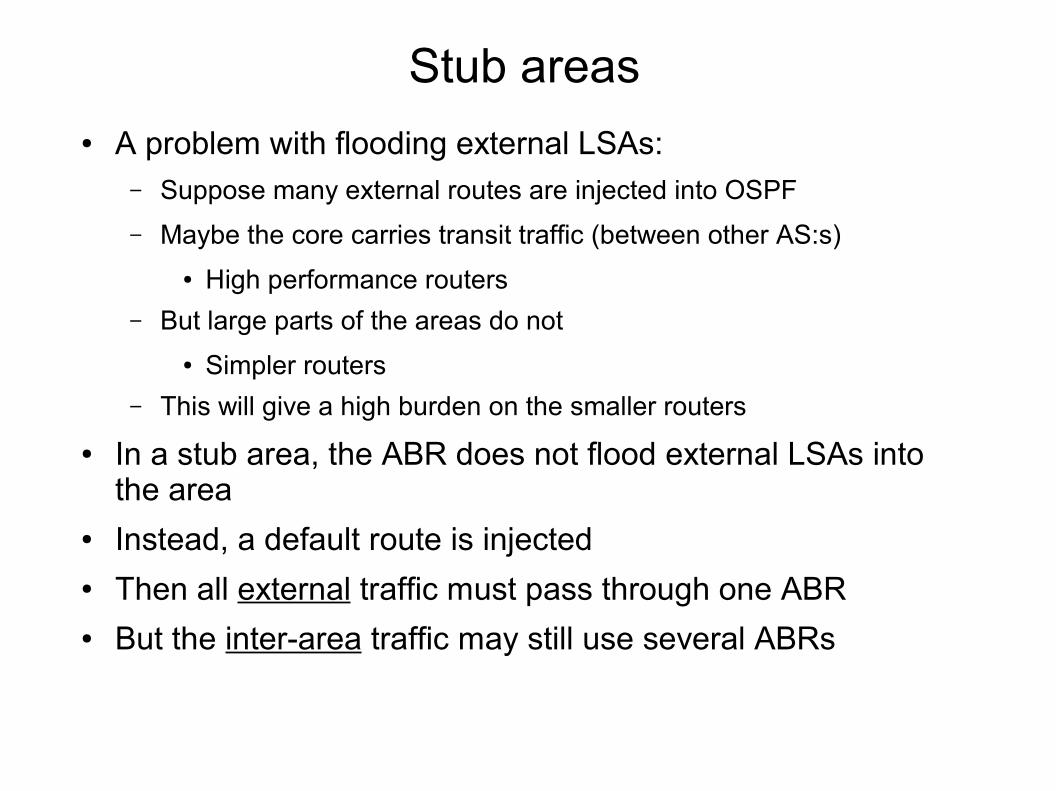
Stub areas● A problem with flooding external LSAs:
– Suppose many external routes are injected into OSPF
– Maybe the core carries transit traffic (between other AS:s)
● High performance routers
– But large parts of the areas do not
● Simpler routers
– This will give a high burden on the smaller routers
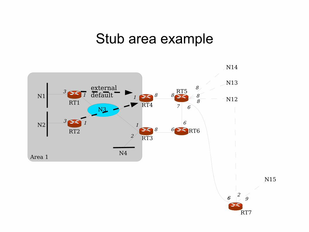
● In a stub area, the ABR does not flood external LSAs into the area
● Instead, a default route is injected● Then all external traffic must pass through one ABR● But the inter-area traffic may still use several ABRs
RT1N1
RT2N2
3
3
N3
1
RT4
1
RT3
N4
2
1
1RT5
RT6
8 8
8 6
N12
N13
N14
N15
8
88
6
7
RT7
6 9
6
62
Area 1
externaldefault
Stub area example
Motivation for NSSA
● Sometimes, the restrictions on stub areas are too strict: – You would like to import a limited number of external routes
● Example: You want to block large routing tables from transit traffic, but want to import a small number of routes
● But in stub areas, you cannot import any external routes.
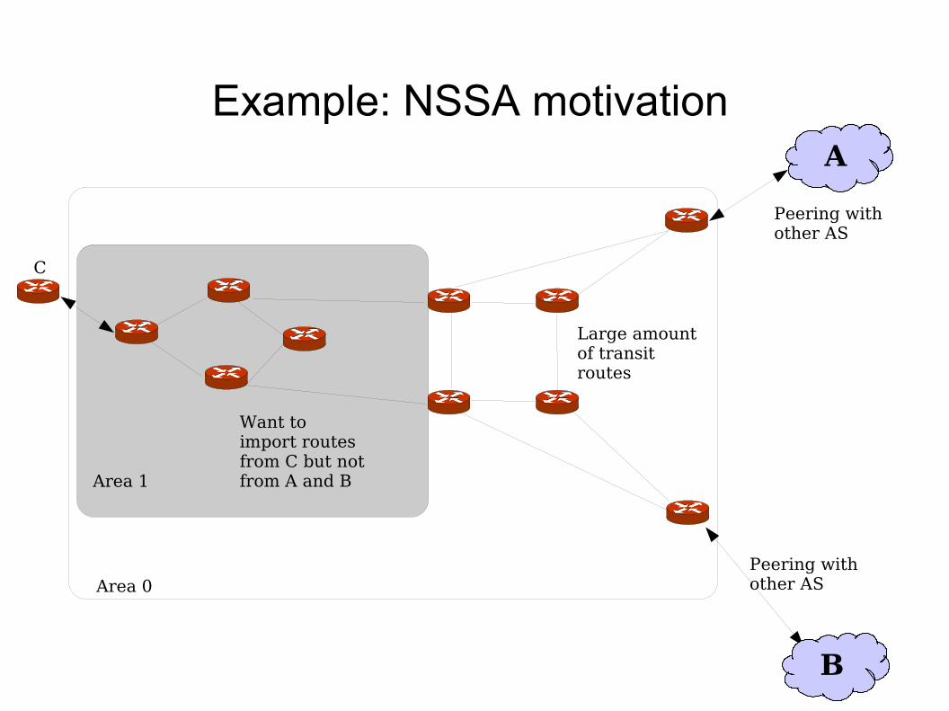
Example: NSSA motivation
Area 1
Area 0
Large amount of transit routes
Peering with other AS
Want to import routes from C but not from A and B
C
Peering with other AS
A
B
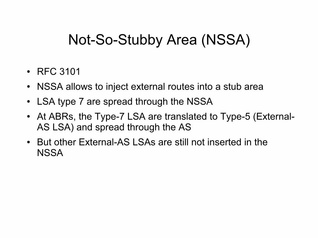
Not-So-Stubby Area (NSSA)
● RFC 3101● NSSA allows to inject external routes into a stub area● LSA type 7 are spread through the NSSA● At ABRs, the Type-7 LSA are translated to Type-5 (External-
AS LSA) and spread through the AS● But other External-AS LSAs are still not inserted in the
NSSA
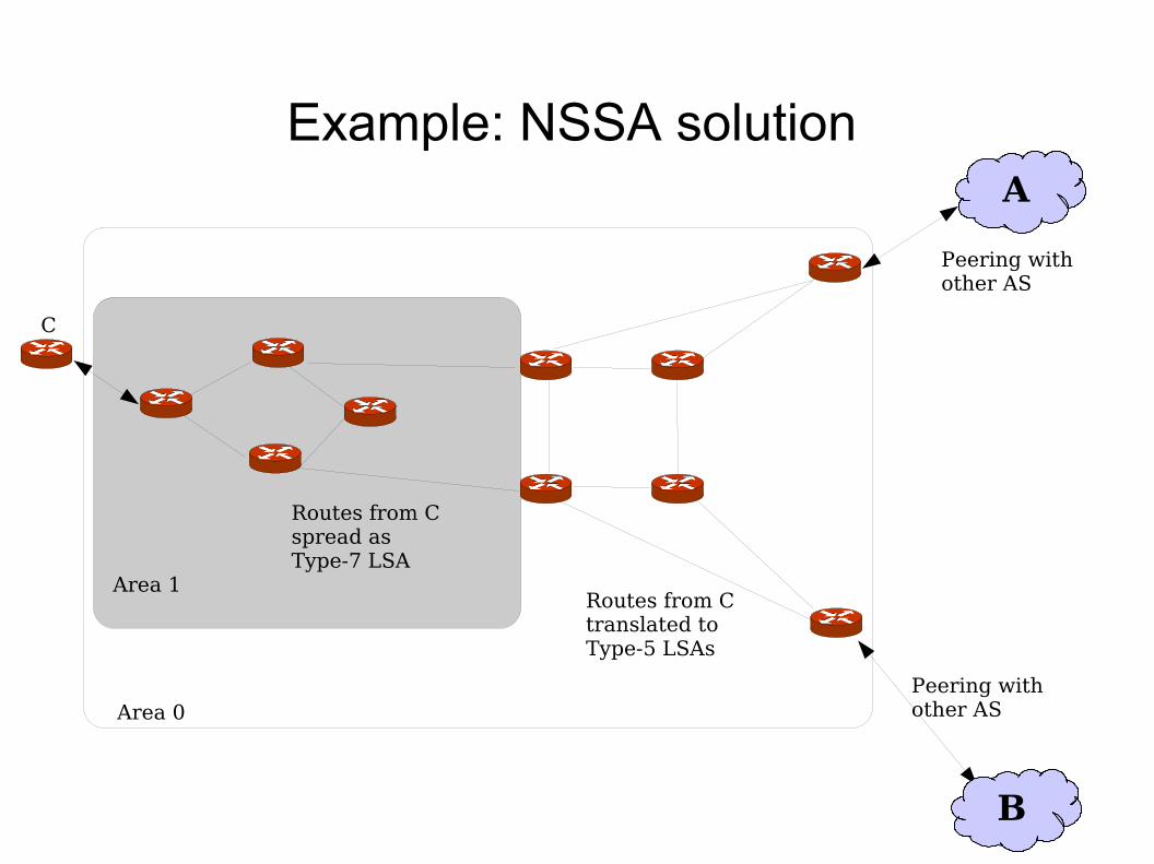
Example: NSSA solution
Area 1
Area 0
Peering with other AS
Routes from Cspread as Type-7 LSA
C
Peering with other AS
A
B
Routes from Ctranslated to Type-5 LSAs
Totally stub areas
● Totally stub area– Do not distribute inter-area routes into an area
● Just use default route
– CISCO-specific
● NSSA totally stub area– Combination of NSSA and totally stub area
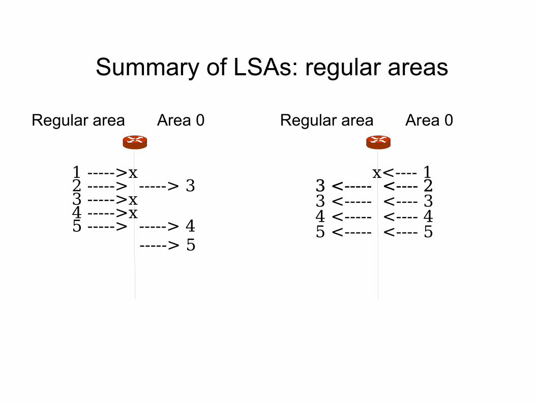
Summary of LSAs: regular areas
Regular area Area 0
1 ----->x2 -----> -----> 33 ----->x4 ----->x5 -----> -----> 4 -----> 5
Regular area Area 0
x<---- 13 <----- <---- 23 <----- <---- 23 <----- <---- 34 <----- <---- 45 <----- <---- 5
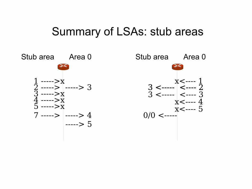
Summary of LSAs: stub areas
Stub area Area 0
1 ----->x2 -----> -----> 33 ----->x4 ----->x5 ----->x7 -----> -----> 4 -----> 5
Stub area Area 0
x<---- 13 <----- <---- 23 <----- <---- 23 <----- <---- 3 x<---- 4 x<---- 5
0/0 <-----
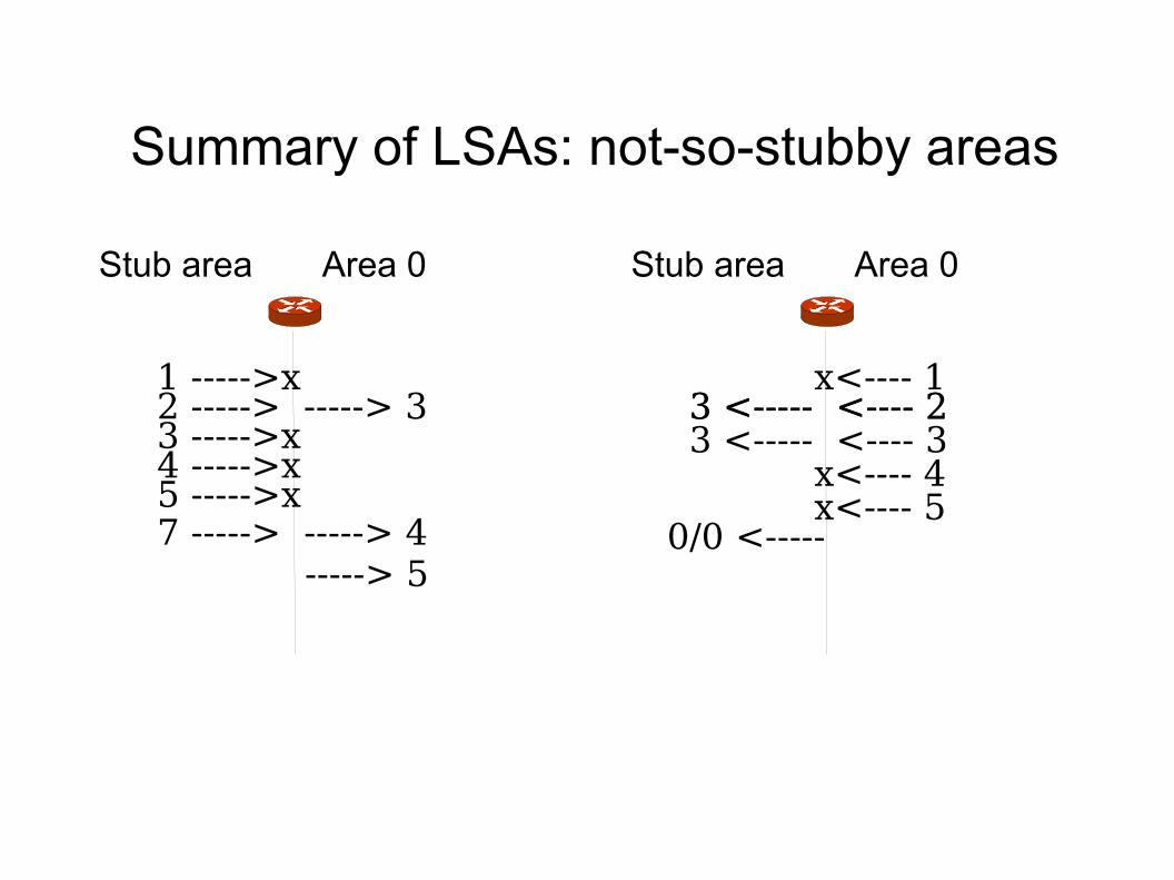
Summary of LSAs: not-so-stubby areas
Stub area Area 0
1 ----->x2 -----> -----> 33 ----->x4 ----->x5 ----->x7 -----> -----> 4 -----> 5
Stub area Area 0
x<---- 13 <----- <---- 23 <----- <---- 23 <----- <---- 3 x<---- 4 x<---- 5
0/0 <-----
Opaque LSA Option
● RFC 2370● For Future extensibility● Standard LSA header● Followed by application-specific information● Three new LSA, difference in scope:
– Type 9-LSA: Link-local scope
– Type 10-LSA: Area-local scope
– Type 11-LSA: AS-local scope
Summary
● This was OSPF essentials● But there are many more issues, for more reading consult:
– RFC 2328
– J Moy, OSPF Anatomy of an Internet Routing Protocol
– Lots of vendor documentation
Traffic Engineering extensions
● RFC 2370● It adds bandwidth and administrative constraints● So that a (network) manager can control traffic in more detail● Distribute it in an area
– Uses Type-10 opaque LSA, area scope
– Call it Traffic Engineering LSA
● The LSA payload contains nested TLVs, for example:● Traffic engineering metric
● Maximum bandwidth
● Maximum reservable bandwidth
● Unreserved bandwidth
● Administrative group
OSPFv3
● OSPF for IPv6 is OSPFv3● Unchanged: Flooding, DR election, area support, SPF calculations, etc● Authentication removed (use IPSEC)● New LSAs for IPv6 addresses● Addressing semantics removed from basic LSAs and msgs
● Avoid IPv4/IPv6 addresses – prefer RouterID
● Network-protocol independence
● Renaming: ● Type-3 summary LSA -> Inter-Area-prefix LSA
● Type-4 summary-LAS -> Inter-Area-router LSA