Link Ball - tech.thk.com
32
Link Ball® General Catalog A22-1 A Product Descriptions B Support Book (Separate) Features and Types ......................... A22-2 Features of the Link Ball .................... A22-2 • Structure and Features ..................... A22-2 • Alloy .............................................. A22-5 • How Load Directions Are Called......... A22-7 • Pushing Load and Pulling Load.......... A22-7 Types of the Link Ball ........................ A22-8 • Types and Features ......................... A22-8 Point of Selection ............................ A22-10 Selecting a Link Ball .......................... A22-10 Dimensional Drawing, Dimensional Table Model BL and Model BL-A................. A22-12 Model RBI .......................................... A22-14 Point of Design ................................ A22-16 Permissible Tilt Angles....................... A22-16 Example of Installation ...................... A22-16 Model No. ......................................... A22-17 • Model Number Coding...................... A22-17 Precautions on Use ......................... A22-18 Features and Types ......................... B22-2 Features of the Link Ball .................... B22-2 • Structure and Features ..................... B22-2 • Alloy .............................................. B22-5 • How Load Directions Are Called......... B22-7 • Pushing Load and Pulling Load.......... B22-7 Performance Tests with the Link Ball .. B22-8 • Durability Tests with Link Ball Model BL .. B22-8 Types of the Link Ball ........................ B22-10 • Types and Features ......................... B22-10 Installation........................................ B22-12 Example of Installation ...................... B22-12 Model No. ......................................... B22-13 • Model Number Coding...................... B22-13 Precautions on Use ......................... B22-14 511E
Transcript of Link Ball - tech.thk.com
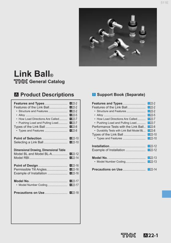
Link Ball®General Catalog
A22-1
A Product Descriptions B Support Book (Separate)
Features and Types ......................... A22-2Features of the Link Ball .................... A22-2
• Structure and Features ..................... A22-2• Alloy .............................................. A22-5• How Load Directions Are Called ......... A22-7• Pushing Load and Pulling Load .......... A22-7
Types of the Link Ball ........................ A22-8• Types and Features ......................... A22-8
Point of Selection ............................ A22-10Selecting a Link Ball .......................... A22-10
Dimensional Drawing, Dimensional TableModel BL and Model BL-A ................. A22-12Model RBI .......................................... A22-14
Point of Design ................................ A22-16Permissible Tilt Angles....................... A22-16Example of Installation ...................... A22-16
Model No. ......................................... A22-17• Model Number Coding ...................... A22-17
Precautions on Use ......................... A22-18
Features and Types ......................... B22-2Features of the Link Ball .................... B22-2
• Structure and Features ..................... B22-2• Alloy .............................................. B22-5• How Load Directions Are Called ......... B22-7• Pushing Load and Pulling Load .......... B22-7
Performance Tests with the Link Ball .. B22-8• Durability Tests with Link Ball Model BL .. B22-8
Types of the Link Ball ........................ B22-10• Types and Features ......................... B22-10
Installation ........................................ B22-12Example of Installation ...................... B22-12
Model No. ......................................... B22-13• Model Number Coding ...................... B22-13
Precautions on Use ......................... B22-14
511E

A22-2
Features of the Link Ball
Shank ball
Boots
Holder
Fig.1 Structure of Link Ball Model BL
Structure and Features
With the Link Ball, a highly accurate bearing steel ball used in the spherical area is fi rst encased in the holder by die cast molding, and then is specially welded with the shank. This unique process enables the mirror surface of the steel ball to be transferred or duplicated on the spherical surface inside the holder to ensure full contact between the ball and the holder. As a result, smooth motion is achieved with a minimum clearance.
Link Ball Features and Types
511E

A22-3
Link Ball
[Compact Design] Model BL has an adequately fi rm and yet extremely compact shape because of a highly balanced design. This model is optimal for use in an automobile height sensor or transmission control.
[Achieves Sphericity of 0.001 mm] The spherical surface of the shank ball is transferred on the inner surface of the holder while main-taining the sphericity of the bearing steel ball. This allows smooth motion to be achieved with a mini-mum clearance and provides favorable operability and feel to the link motion.
Sphericity: 0.001 mm
Sphericity of the spherical surface of the ball shank
1μm
0.2μ
m
0.1mm VER.x HOR.x mm λc=
Roughness of the spherical surface of the ball shank
VER.x HOR.x 0.1mm
1μm
0.4μ
m
TOKYO SEIMITSU
Roughness of the spherical surface of the holder
Cut sample of the spherical area of model BL
Features and TypesFeatures of the Link Ball
511E

A22-4
[Two Types of Holder Material] Model BL-A uses the newly developed high strength aluminum alloy“A-1 Alloy”(see A22-5 ), which is l ight and highly resistant to wear. Models BL6 and above and model RBI uses the proven high strength zinc alloy (see A22-6 ).
[High Lubricity] The boot contains grease for high lubricity and increased wear resistance.
[Large Hexagonal Bolt Seat] The hexagonal bolt seat of the shank has the same dimensions as the seating surface for small hexagon head bolts in accordance with automotive specifications. This prevents the seating surface from sinking and ensures a stable link motion mechanism.
[Equipped with a Boot for Protection against Muddy Water] Use of a boot with high trackability in the ball shank prevents muddy water from entering the spherical area even in a muddy atmosphere. Accordingly, those types equipped with boots are used also in outdoor applications and auto-mobile parts under the chassis. For details, see the muddy water test data ( B22-8 and B22-9 ).
A-A cross section
Model equivalent to similar product
Model BL10
14 12
A
A
2α
Jaw Span for Wrenching
511E

A22-5
Link Ball
Alloy
[High Strength Aluminum Alloy “A-1 Alloy”] “A-1 Alloy,” a newly developed high strength aluminum alloy, is an alloy with Aℓ-Zn-Si3 being the main components, is used in the holder of model BL-A. Information on the mechanical properties, physical properties, and wear resistance of materials is presented below. *The fi gures shown are target values—these fi gures are not guaranteed.
Features of the A-1 Alloy • Achieves one of the highest strengths among the existing aluminum die cast alloys. • Has yield strength approximately twice that of the commonly used aluminum die cast alloy (ADC
12). • Has hardness equal to the high strength zinc alloy and achieves high wear resistance. • Achieves specifi c gravity less than a half of the high strength zinc alloy to allow signifi cant weight
saving. • Highly corrosion resistance and can be used as an automotive part related to wheel control.
Mechanical Properties Tensile strength : 343 to 392 N/mm 2 Tensile yield strength (0.2%) : 245 to 294 N/mm 2 Compressive strength : 490 to 637 N/mm 2 Compressive yield strength (0.2%) : 294 to 343 N/mm 2 Charpy impact : 0.098 to 0.196 N-m/mm 2 Elongation : 2 to 3 % Hardness : 140 to 160 HV
Physical Properties Specifi c gravity : 3 Melting point : 570℃ Specifi c heat : 793 J/(kg•k) Linear expansion rate : 22×10 -6
Features and TypesFeatures of the Link Ball
511E

A22-6
[High Strength Zinc Alloy] The high strength zinc alloy used in the holders of models BL and RBI has been developed as a bearing alloy by mixing Aℓ, Cu, Mg, Be and Ti as well as zinc as the base component. It is excellent in mechanical properties, seizure resistance and wear resistance. Information on mechanical prop-erties, physical properties, and wear resistance is presented below. *The fi gures shown are target values—these fi gures are not guaranteed.
Mechanical Properties Tensile strength : 275 to 314 N/mm 2 Tensile yield strength (0.2%) : 216 to 245 N/mm 2 Compressive strength : 539 to 686 N/mm 2 Compressive yield strength (0.2%) : 294 to 343 N/mm 2 Fatigue strength : 132 N/mm 2 ×10 7 (Schenk bending test) Charpy impact : 0.098 to 0.49 N-m/mm 2 Elongation : 1 to 5% Hardness : 120 to 145 HV
Physical Properties Specifi c gravity : 6.8 Melting point : 390℃ Specifi c heat : 460 J/(kg•k) Linear expansion rate : 24×10 -6
Wear Resistance The wear resistance of the high strength zinc alloy is superior to that of class-3 brass and class-3 bronze, almost equal to that of class-2 phosphor bronze. Amsler wear-tester Test piece rotation speed : 185 min -1 Load : 392 N Lubricant : Dynamo oil
Distance (km) (load:392N)
Class-2 phosphor bronze
Class-3 bronze
THK high strength zinc alloy
Class-3 brass
Wea
r los
s (m
g)
80
60
40
20
0 10 20 30 40 50 60 70 80 90 100
Fig.2 Wear Resistance of the High Strength Zinc Alloy
511E
A22-7
Link Ball
How Load Directions Are Called
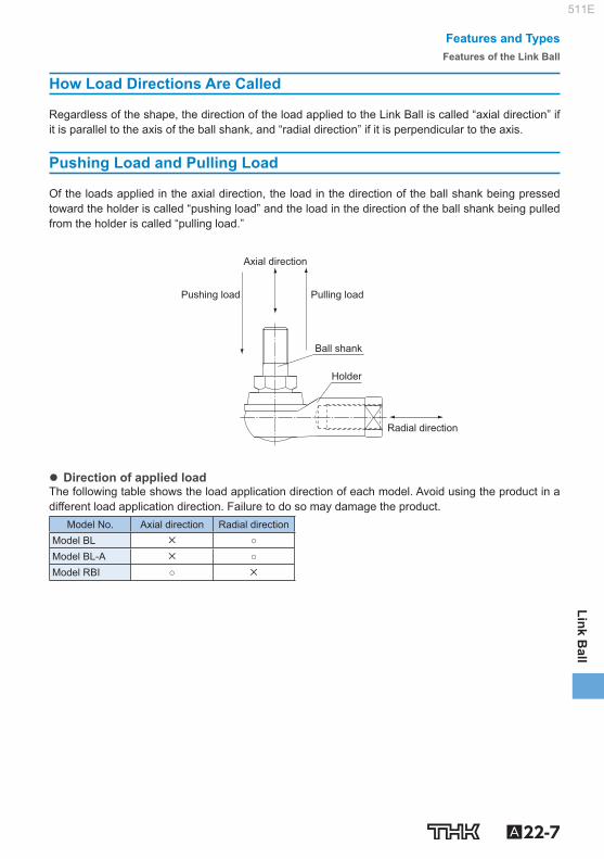
Regardless of the shape, the direction of the load applied to the Link Ball is called “axial direction” if it is parallel to the axis of the ball shank, and “radial direction” if it is perpendicular to the axis.
Pushing Load and Pulling Load
Of the loads applied in the axial direction, the load in the direction of the ball shank being pressed toward the holder is called “pushing load” and the load in the direction of the ball shank being pulled from the holder is called “pulling load.”
Holder
Ball shank
Pulling load
Axial direction
Radial direction
Pushing load
Direction of applied load The following table shows the load application direction of each model. Avoid using the product in a different load application direction. Failure to do so may damage the product.
Model No. Axial direction Radial direction Model BL × ○ Model BL-A × ○ Model RBI ○ ×
Features and TypesFeatures of the Link Ball
511E
A22-8
Types of the Link Ball Types and Features
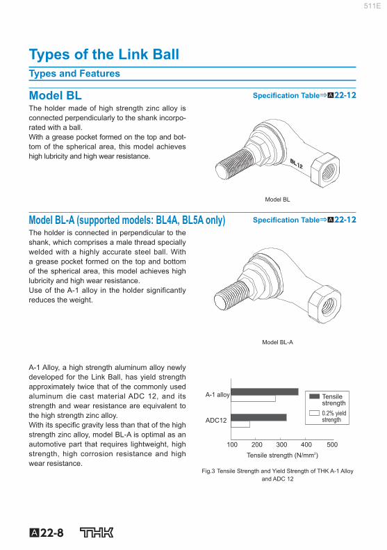
Model BL Specifi cation Table⇒A22-12 The holder made of high strength zinc alloy is connected perpendicularly to the shank incorpo-rated with a ball. With a grease pocket formed on the top and bot-tom of the spherical area, this model achieves high lubricity and high wear resistance.
Model BL
Model BL-A (supported models: BL4A, BL5A only) Specifi cation Table⇒A22-12 The holder is connected in perpendicular to the shank, which comprises a male thread specially welded with a highly accurate steel ball. With a grease pocket formed on the top and bottom of the spherical area, this model achieves high lubricity and high wear resistance. Use of the A-1 alloy in the holder significantly reduces the weight.
Model BL-A
A-1 Alloy, a high strength aluminum alloy newly developed for the Link Ball, has yield strength approximately twice that of the commonly used aluminum die cast material ADC 12, and its strength and wear resistance are equivalent to the high strength zinc alloy. With its specifi c gravity less than that of the high strength zinc alloy, model BL-A is optimal as an automotive part that requires lightweight, high strength, high corrosion resistance and high wear resistance.
Tensile strength 0.2% yield strength
A-1 alloy
Tensile strength (N/mm2)
ADC12
100 200 300 400 500
Fig.3 Tensile Strength and Yield Strength of THK A-1 Alloy and ADC 12
511E

A22-9
Link Ball
Model RBI Specifi cation Table⇒A22-14 With this Link Ball model, the high strength zinc alloy is used in its holder, and the mounting bolt and the holder are arranged on the same axis, allowing this model to receive an axial load. Since grease is contained in the boot, this model achieves high lubricity and high wear re-sistance.
Model RBI
Features and TypesTypes of the Link Ball
511E

A22-10
Selecting a Link Ball The selected bearing must meet both the permissible load obtained from equation (1) and the dy-namic load capacity obtained from equation (2).
[Permissible Load P] The yield-point strength indicated in the specifi cation tables refers to the mechanical strength of the bearing. For model BL, the yield-point strength indicates the strength when a load is applied to the ball shank in a radial direction. For model RBI, it indicates the strength when a load is applied to the ball shank in an axial direction with respect to the holder. (For the load direction, see A22-7 .)
Table1 Safety Factor (f S )
Type of load Lower limit of f S
Constant load in a constant direction 2 to 3
Fluctuating load in a constant direction 3 to 5
Load in varying directions 5 to 8
According to the type of the load, select a bearing that satisfi es the following equation from a me-chanical strength’s viewpoint.
…………(1) Pk
fS P
P : Permissible Load (N) P k : Yield-point strength (N) f S : Safety factor (see Table1 )
[Dynamic Load Capacity C d ] The dynamic load capacity (C d ) refers to the upper limit of load that the spherical area of the Link Ball can receive without showing seizure while the Link Ball is rotating or oscillating. The dynamic load capacity is obtained from the following approximation formula using the static load capacity (C S ) (note) indicated in the dimensional table.
…………(2)
n 3
CSCd =
C d : Dynamic load capacity (N) C s : Static load capacity (N) n : Revolutions per minute (min ‒1 ) Note) Static load capacity (C S ) refers to the value obtained by multiplying the projected area on the spherical section by the
permissible surface pressure, and is used to obtain the dynamic load capacity.
Link Ball Point of Selection
511E

A22-11
Link Ball
Point of SelectionSelecting a Link Ball
511E

A22-12 To download a desired data, search for the corresponding model number in the Technical site. https://tech.thk.com
Model BL and Model BL-A
M1 M M2
ℓ1
L L1
ℓ
L2
φ d2
φ Da
d4 φ D1
2θ
S1
S1
Model No.
Outer dimensions Threaded Holder dimensions
Length Diameter Height S 1 L 1 ℓ L 2 D 1 D 2 W
L D M JIS Class 2 0 –0.3
BL 4DA 24.5 13 20 M4×0.7 18 8 4 7.5 9.5 8 BL 5DA 34.5 15 26.7 M5×0.8 27 15 4 9 12 10 BL 6D 38 16 32.6 M6×1 30 16 5 10 13 11 BL 8D 45.5 19 38.6 M8×1.25 36 19 6 12.5 16 14 BL 10D 55.5 25 46.3 M10×1.25 43 23 7 14.5 19 17 BL 10BD 55.5 25 52.3 M10×1.5 43 23 7 14.5 19 17 BL 12D 64.5 29 52.7 M12×1.25 50 26 8 17.5 22 19 BL 12BD 64.5 29 59.7 M12×1.75 50 26 8 17.5 22 19 BL 14D 74 34 68.4 M14×1.5 57 30 10 20 25 22 BL 14BD 74 34 74.4 M14×2 57 30 10 20 25 22 BL 16D 83 38 74 M16×1.5 64 34 11 22 27 24 BL 16BD 83 38 80 M16×2 64 34 11 22 27 24
Note) Model BL-A is only available in size 4 and 5.
[Material] Holder : A-1 alloy (BL4 to 5) (see A22-5 )
: High strength zinc alloy (BL6 to 16) (see A22-6 ) Ball shank : Lightly Carburized Carbon Steel Ball: 650 HV or higher Shank S35C (20 to 28 HRC) Chromate treatment Boot : NBR special synthetic rubber
[Spherical Clearance] Radial direction : 0.02 to 0.06mm Axial direction : 0.3mm or less [Tolerance of the Mating Hole of the Ball Shank] H10 is recommended
.
With boot attached
Model number
Screw symbol
Screw symbol No symbol
Holder unit set screw
Ball shank
Right-hand Left-hand
Right-hand
BL6 D L L
Note) No model is available without boot.
Model number coding
511E

A22-13
Link Ball
W
W φ D
φ D2B
Unit: mm
Ball shank dimensions Ball diam-eter
Permissible tilt angles
Applied static load
Yield-point strength Mass
d 2 M 1 M 2 ℓ 1 HexagonB d 4 Da 2 C s P k g
h9 0.3 0 –0.3 N N
4 15 7 6 7 8.1 7.938 40 4510 1370 7 5 21 10 8 8 9.2 9.525 40 6470 2250 12 6 26 11 11 10 11.6 11.112 40 9900 3920 26 8 31 14 12 12 13.8 12.7 40 12500 6570 49
10 37 17 15 14 16.2 15.875 40 18300 11300 87 10 43 17 21 14 16.2 15.875 40 18300 11300 90 12 42 19 17 17 19.6 19.05 40 26700 16400 143 12 49 19 24 17 19.6 19.05 40 26700 16400 148 14 56 21.5 22 19 21.9 22.225 40 36400 19800 235 14 62 21.5 28 19 21.9 22.225 40 36400 19800 245 16 60 23.5 23 22 25.4 22.225 30 36400 26900 315 16 66 23.5 29 22 25.4 22.225 30 36400 26900 325
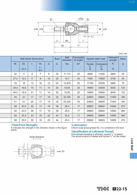
[Yield-Point Strength] It indicates the strength in the direction shown in the fi gure below.
Rad
ial d
irect
ion
PK
[Lubrication] Lithium soap group grease No. 2 is contained in the boot and the cap. [Identifi cation of Left-hand Thread] If the female threading is left-handed, its identifi cation de-pends on the marking.
Threaded Identifi cation Cap marking
Right-hand — Left-hand L mark
511E

A22-14 To download a desired data, search for the corresponding model number in the Technical site. https://tech.thk.com
Model RBI
W1 φ D2
φ d2φ D1
2θ
Model No.
Outer dimen-sions Threaded Holder dimensions Shaft di-
ameter
Length Diameter S 1 L 1 L 2 ℓ D 1 D 2 W d 2
L D JIS Class 2 0 –0.3 h9
RBI 5D 46 17 M5×0.8 24 4 12 9 11 9 5
RBI 6D 55.2 20 M6×1 28 5 15 10 13 11 6
RBI 8D 65 24 M8×1.25 32 5 16 12.5 16 14 8
RBI 10D 74.5 28 M10×1.25 35 6.5 18 15 19 17 10
RBI 10BD 80.5 28 M10×1.5 35 6.5 18 15 19 17 10
RBI 12D 84 32 M12×1.25 40 6.5 20 17.5 22 19 12
RBI 12BD 91 32 M12×1.75 40 6.5 20 17.5 22 19 12
RBI 14D 103 36 M14×1.5 45 8 25 20 25 22 14
RBI 14BD 109 36 M14×2 45 8 25 20 25 22 14
RBI 16D 112 40 M16×1.5 50 8 27 22 27 22 16
RBI 16BD 118 40 M16×2 50 8 27 22 27 22 16
[Material] Holder : High strength zinc alloy (see A22-6 ) Ball shank : Bearing steel ball Hardness: 650 HV or higher Shank S35C Chromate treatment Boot : NBR special synthetic rubber
[Spherical Clearance] Radial direction : 0.03mm or less Axial direction : 0.1mm or less [Tolerance of the Mating Hole of the Ball Shank] H10 is recommended.
Model number
Screw symbol With boot attached
Screw symbol No symbol
Holder unit set screw
Ball shank
Right-hand Left-hand
Right-hand
RBI10 D L L
Note) No model is available without boot.
Model number coding
511E
A22-15
Link Ball
M1
M2ℓ1
W
L
L1
L2
φ D
ℓ
φ d4φ d5
φ Da S1S1
Unit: mm
Ball shank dimensions Boot Ball diameter
Permissible tilt angles Applied static load Yield-point
strength Mass
M 1 M 2 ℓ 1 W 1 d 4 d 5 Da 2 Tensile C s N
Compressive C s N
P k g
0.3 0 –0.3 N
22 11 8 7 9 20 11.112 25 5690 11400 2840 25
27.2 12.2 11 8 10 20 12.7 25 7450 14900 3730 40
33 16 12 10 12 24 15.875 25 11700 23200 5880 75
39.5 19.5 15 11 14 30 19.05 25 16800 33500 8430 120
45.5 19.5 21 11 14 30 19.05 25 16800 33500 8430 123
44 21 17 17 19 32 22.225 25 22800 45600 11400 185
51 21 24 17 19 32 22.225 25 22800 45600 11400 190
58 23.5 22 17 19 38 25.4 17 29800 59600 14900 275
64 23.5 28 17 19 38 25.4 17 29800 59600 14900 280
62 25.5 23 19 22 44 25.4 17 29800 59600 14900 360
68 25.5 29 19 22 44 25.4 17 29800 59600 14900 370
[Yield-Point Strength] It indicates the strength in the direction shown in the fi gure below.
Axial direction
PK
[Lubrication] Lithium soap group grease No. 2 is contained in the boot.
[Identifi cation of Left-hand Thread] If the female threading is left-hand, symbol “L” is added. The actual product is marked with symbol “L” on the holder.
511E

A22-16
Permissible Tilt Angles The permissible tilting angles of Link Ball models are indicated in the corresponding specifi cation tables. Note) If the permissible tilt angle is exceeded, it may cause serious damage to the holder or the boot. Be sure to use the Link
Ball within its permissible tilt angle.
Example of Installation [Comparison of THK Link Ball and the Conventional Rod End]
Flange
Washer
Shaft
Conventional Rod End model PHSTHK model BL
● Sine it has a shaft, model BL can easily be installed (especially useful for rod assembly). ● Because of the improved shape of the boot lip, the spherical area is protected from muddy water
even in a muddy atmosphere. ● Since it contains grease, it can be used without further lubrication. ● Unlike the conventional type, which has a clearance between the shaft and the inner circumference
of the inner ring and cannot be fi xed completely, model BL has minimum distortion and high rigidity since the shank is integrated with the ball.
[Examples of Installing Model RBI]
Joint for cylinder end metal fitting
Connecting a rod in the axial direction
Rotation support
Rotation
Suspending a light object
Force
Force
ForceForce
Link Ball Point of Design
511E
A22-17
Link Ball
Model Number Coding
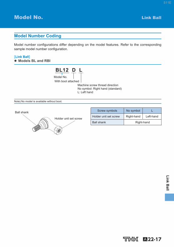
Model number confi gurations differ depending on the model features. Refer to the corresponding sample model number confi guration.
[Link Ball] Models BL and RBI
Machine screw thread direction No symbol: Right hand (standard)L: Left hand
With boot attached Model No.
BL12 D L
Note) No model is available without boot.
Holder unit set screw
Ball shank Screw symbols No symbol L
Holder unit set screw Right-hand Left-hand
Ball shank Right-hand
Link Ball Model No.
511E

A22-18
[Service Temperature] The service temperature of the Link Ball series is basically between ‒20℃ and 80℃. If the service tempera-ture exceeds this range, contact THK. (See examples of testing the product at temperature other than the above service temperature range on B22-8 to B22-9 .)
[Handling] (1) Do not disassemble the parts. This will result in loss of functionality. (2) Take care not to drop or strike the Link Ball. Doing so may cause injury or damage. Giving an
impact to it could also cause damage to its function even if the product looks intact. (3) When handling the product, wear protective gloves, safety shoes, etc., as necessary to ensure
safety.
[Precautions on Use] (1) Do not use the product in the manner that the permissible tilting angle is exceeded since doing
so may damage the product. (2) Prevent foreign material, such as cutting chips or coolant, from entering the product. Failure to
do so may cause damage. (3) Model BL is designed for use under loading in radial direction, while model RBI is designed for
use under loading in axial direction. (4) Insuffi cient rigidity or accuracy of mounting members causes the bearing load to concentrate on
one point and the bearing performance will drop signifi cantly. Accordingly, give suffi cient consid-eration to the rigidity/accuracy of the housing and base and strength of the fi xing bolts.
[Lubrication] (1) Lithium soap group grease No. 2 is contained in all boots and can be used without further greas-
ing. (2) Do not mix different lubricants. Mixing greases using the same type of thickening agent may still
cause adverse interaction between the two greases if they use different additives, etc. (3) When using the product in locations exposed to constant vibrations or in special environments
such as clean rooms, vacuum and low/high temperature, use the grease appropriate for the specifi cation/environment.
[Storage] When storing the Link Ball, enclose it in a package designated by THK and store it in a room while avoiding high temperature, low temperature and high humidity.
[Disposal] Dispose of the product properly as industrial waste.
Link Ball Precautions on Use
511E

Link Ball®General Catalog
B22-1
Features and Types ......................... B22-2Features of the Link Ball .................... B22-2
• Structure and Features ..................... B22-2• Alloy .............................................. B22-5• How Load Directions Are Called ......... B22-7• Pushing Load and Pulling Load .......... B22-7
Performance Tests with the Link Ball .. B22-8• Durability Tests with Link Ball Model BL .. B22-8
Types of the Link Ball ........................ B22-10• Types and Features ......................... B22-10
Installation ........................................ B22-12Example of Installation ...................... B22-12
Model No. ......................................... B22-13• Model Number Coding ...................... B22-13
Precautions on Use ......................... B22-14
Features and Types ......................... A22-2Features of the Link Ball .................... A22-2
• Structure and Features ..................... A22-2• Alloy .............................................. A22-5• How Load Directions Are Called ......... A22-7• Pushing Load and Pulling Load .......... A22-7
Types of the Link Ball ........................ A22-8• Types and Features ......................... A22-8
Point of Selection ............................ A22-10Selecting a Link Ball .......................... A22-10
Dimensional Drawing, Dimensional TableModel BL and Model BL-A ................. A22-12Model RBI .......................................... A22-14
Point of Design ................................ A22-16Permissible Tilt Angles....................... A22-16Example of Installation ...................... A22-16
Model No. ......................................... A22-17• Model Number Coding ...................... A22-17
Precautions on Use ......................... A22-18
B Support Book A Product Descriptions (Separate)
511E

B22-2
Features of the Link Ball
Shank ball
Boots
Holder
Fig.1 Structure of Link Ball Model BL
Structure and Features
With the Link Ball, a highly accurate bearing steel ball used in the spherical area is fi rst encased in the holder by die cast molding, and then is specially welded with the shank. This unique process enables the mirror surface of the steel ball to be transferred or duplicated on the spherical surface inside the holder to ensure full contact between the ball and the holder. As a result, smooth motion is achieved with a minimum clearance.
Link Ball Features and Types
511E

B22-3
Link Ball
[Compact Design] Model BL has an adequately fi rm and yet extremely compact shape because of a highly balanced design. This model is optimal for use in an automobile height sensor or transmission control.
[Achieves Sphericity of 0.001 mm] The spherical surface of the shank ball is transferred on the inner surface of the holder while main-taining the sphericity of the bearing steel ball. This allows smooth motion to be achieved with a mini-mum clearance and provides favorable operability and feel to the link motion.
Sphericity: 0.001 mm
Sphericity of the spherical surface of the ball shank
1μm
0.2μ
m
0.1mm VER.x HOR.x mm λc=
Roughness of the spherical surface of the ball shank
VER.x HOR.x 0.1mm
1μm
0.4μ
m
TOKYO SEIMITSU
Roughness of the spherical surface of the holder
Cut sample of the spherical area of model BL
Features and TypesFeatures of the Link Ball
511E

B22-4
[Two Types of Holder Material] Model BL-A uses the newly developed high strength aluminum alloy “A-1 Alloy” (see B22-5 ), which is l ight and highly resistant to wear. Models BL6 and above and model RBI uses the proven high strength zinc alloy (see B22-6 ).
[High Lubricity] The boot contains grease for high lubricity and increased wear resistance.
[Large Hexagonal Bolt Seat] The hexagonal bolt seat of the shank has the same dimensions as the seating surface for small hexagon head bolts in accordance with automotive specifications. This prevents the seating surface from sinking and ensures a stable link motion mechanism.
[Equipped with a Boot for Protection against Muddy Water] Use of a boot with high trackability in the ball shank prevents muddy water from entering the spherical area even in a muddy atmosphere. Accordingly, those types equipped with boots are used also in outdoor applications and auto-mobile parts under the chassis. For details, see the muddy water test data ( B22-8 and B22-9 ).
A-A cross section
Model equivalent to similar product
Model BL10
14 12
A
A
2α
Jaw Span for Wrenching
511E
B22-5
Link Ball
Alloy
[High Strength Aluminum Alloy “A-1 Alloy”] “A-1 Alloy,” a newly developed high strength aluminum alloy, is an alloy with Aℓ-Zn-Si3 being the main components, is used in the holder of model BL-A. Information on the mechanical properties, physical properties, and wear resistance of materials is presented below. *The fi gures shown are target values—these fi gures are not guaranteed.
Features of the A-1 Alloy • Achieves one of the highest strengths among the existing aluminum die cast alloys. • Has yield strength approximately twice that of the commonly used aluminum die cast alloy (ADC
12). • Has hardness equal to the high strength zinc alloy and achieves high wear resistance. • Achieves specifi c gravity less than a half of the high strength zinc alloy to allow signifi cant weight
saving. • Highly corrosion resistance and can be used as an automotive part related to wheel control.
Mechanical Properties Tensile strength : 343 to 392 N/mm 2 Tensile yield strength (0.2%) : 245 to 294 N/mm 2 Compressive strength : 490 to 637 N/mm 2 Compressive yield strength (0.2%) : 294 to 343 N/mm 2 Charpy impact : 0.098 to 0.196 N-m/mm 2 Elongation : 2 to 3 % Hardness : 140 to 160 HV
Physical Properties Specifi c gravity : 3 Melting point : 570℃ Specifi c heat : 793 J/(kg•k) Linear expansion rate : 22×10 -6
Features and TypesFeatures of the Link Ball
511E

B22-6
[High Strength Zinc Alloy] The high strength zinc alloy used in the holders of models BL and RBI has been developed as a bearing alloy by mixing Aℓ, Cu, Mg, Be and Ti as well as zinc as the base component. It is excellent in mechanical properties, seizure resistance and wear resistance. Information on mechanical prop-erties, physical properties, and wear resistance is presented below. *The fi gures shown are target values—these fi gures are not guaranteed.
Mechanical Properties Tensile strength : 275 to 314 N/mm 2 Tensile yield strength (0.2%) : 216 to 245 N/mm 2 Compressive strength : 539 to 686 N/mm 2 Compressive yield strength (0.2%) : 294 to 343 N/mm 2 Fatigue strength : 132 N/mm 2 ×10 7 (Schenk bending test) Charpy impact : 0.098 to 0.49 N-m/mm 2 Elongation : 1 to 5% Hardness : 120 to 145 HV
Physical Properties Specifi c gravity : 6.8 Melting point : 390℃ Specifi c heat : 460 J/(kg•k) Linear expansion rate : 24×10 -6
Wear Resistance The wear resistance of the high strength zinc alloy is superior to that of class-3 brass and class-3 bronze, almost equal to that of class-2 phosphor bronze. Amsler wear-tester Test piece rotation speed : 185 min -1 Load : 392 N Lubricant : Dynamo oil
Distance (km) (load:392N)
Class-2 phosphor bronze
Class-3 bronze
THK high strength zinc alloy
Class-3 brass
Wea
r los
s (m
g)
80
60
40
20
0 10 20 30 40 50 60 70 80 90 100
Fig.2 Wear Resistance of the High Strength Zinc Alloy
511E

B22-7
Link Ball
How Load Directions Are Called
Regardless of the shape, the direction of the load applied to the Link Ball is called “axial direction” if it is parallel to the axis of the ball shank, and “radial direction” if it is perpendicular to the axis.
Pushing Load and Pulling Load
Of the loads applied in the axial direction, the load in the direction of the ball shank being pressed toward the holder is called “pushing load” and the load in the direction of the ball shank being pulled from the holder is called “pulling load.”
Holder
Ball shank
Pulling load
Axial direction
Radial direction
Pushing load
Direction of applied load The following table shows the load application direction of each model. Avoid using the product in a different load application direction. Failure to do so may damage the product.
Model No. Axial direction Radial direction Model BL × ○ Model BL-A × ○ Model RBI ○ ×
Features and TypesFeatures of the Link Ball
511E

B22-8
Performance Tests with the Link Ball Durability Tests with Link Ball Model BL
[Purpose of the Tests] The tests were conducted to identify the performance difference between THK Link Ball model BL and an equivalent product of a competitor. As a result, model BL has been used in joints for transmission control units of automobiles, trucks and buses and for steering mechanisms of agricultural tractors.
[Tested Product, Test Items, Test Conditions and Test Results]
Test item
Tested model
No.
Test conditions
Applied load
Rotation or
rocking angle
Frequency Total num-ber of rev-olutions or
time
Service environ-
ment Load conditions, etc.
Rotation-and-
rocking durabil-
ity
Compar-ison of THK
Link Ballmodel BL10D
andcompet-
itor’s product
1760N(Radial
direction)
Rotation angle: =20 Rocking angle: =20
40 times/min.
1,000,000 cycles
Normal tem-
perature
The loading diagram is as follows.
1 cycle 1.5 sec. Load: N
+1760
–1760
0
The motion direction is as follows:
Rocking Rotation θ θ
Low-tempera-
ture rotation
durability
THK Link Ball model BL10D only
1225N(Radial
direction)
Rotation angle: =30
60 times/min.
−30℃ Low-temperature retention time: 280 hours Motion in the rotational direction
High tempera-
ture rotation durability
100℃ High temperature retention time: 280 hours Motion in the rotational direction
Muddy-water
rotation durability
Normal tem-
perature
Motion: rotational direction and oscillation on a separate basis Muddy water discharge pattern Muddy water concentration: 5 Wt% of salt and dust each in 1 liter of water Discharge direction: against the boot lip Discharge pressure: 5 kg/cm 3
Dry
1 cycle
Muddy water
×23 cycles(5Hr) (19Hr)
(24Hr) (552Hr)
Muddy-water
rocking durability
Compar-ison of THK
Link Ball model BL10D
andcompet-
itor’sproduct
Rocking angle: =20
511E

B22-9
Link Ball
[Comprehensive Evaluation] As a result of comparing THK Link Ball model BL10D and a competitor’s product in representative durability tests, it is demonstrated that model BL10D is superior in strength and wear resistance of the holder and sealability of the boot. These features are achieved through THK’s unique manufacturing process for the holder and the shank, the material used, the structure of upper and lower grease pockets on the spherical area and the development of a highly sealable boot.
Test Result
Evaluation Sample
No.
Change in clearance (m)
Conditions of the holder, etc. Radial
direction Axial
direction
THK model BL10D
(1) 26 42 The shank was capable of smoothly rotating after the 1-million cycle test, and ca-pable of continuously operat-ing.
● Even in complex link motion, THK model BL10D demonstrated higher durability and wear resistance of the holder than competi-tor’s product. (2) 25 40
Com-petitor’s product
(1)
Broke in the holder neck after 8,600 cycles
Wear and damage were observed in the holder ’s spherical area in approx. 150,000-cycle operation.
● The abrasion loss of the competitor’s prod-uct immediately before the breakage of the holder was 6 times greater than THK model BL10D (Radial direction).
154 60
(2)
Broke in the holder neck after 151,300 cycles
62 20
THK model BL10D
(1) 63 65 The boot did not show a crack or the like at low tem-perature
● This indicates that THK model BL10D is suf-fi ciently capable of operating in outdoor ap-plications in cold climates. (2) 56 59
(1) 79 84 The holder did not show abnormal wear and the boot did not show thermal deteri-oration at high temperature.
● This indicates that THK model BL10D is suf-fi ciently capable of operating in hot areas of a truck engine. (2) 74 78
(1) 48 51
No muddy-water penetra-tion that may cause wear was observed.
● This indicates that THK model BL10D is suf-fi ciently capable of operating in environments subject to muddy water such as trucks, con-struction vehicles and agricultural machines since the sealing effect of the boot prevents penetration of muddy water.
(2) 57 63
(1) 32 38
(2) 35 42
Com-petitor’s product
(1) 240 105 Muddy water penetrated the boot, the spherical area showed chipping and the boot had cuts.
● The competitor’s product cannot be used in environments subject to muddy water since chipping or the like may occur in such envi-ronments. In addition, wear of the spherical area reached 0.24 mm, 7.4 times greater than THK model BL10D. (2) 246 107
Features and TypesPerformance Tests with the Link Ball
511E

B22-10
Types of the Link Ball Types and Features
Model BL Specifi cation Table⇒A22-12 The holder made of high strength zinc alloy is connected perpendicularly to the shank incorpo-rated with a ball. With a grease pocket formed on the top and bot-tom of the spherical area, this model achieves high lubricity and high wear resistance.
Model BL
Model BL-A (supported models: BL4A, BL5A only) Specifi cation Table⇒A22-12 The holder is connected in perpendicular to the shank, which comprises a male thread specially welded with a highly accurate steel ball. With a grease pocket formed on the top and bottom of the spherical area, this model achieves high lubricity and high wear resistance. Use of the A-1 alloy in the holder significantly reduces the weight.
Model BL-A
A-1 Alloy, a high strength aluminum alloy newly developed for the Link Ball, has yield strength approximately twice that of the commonly used aluminum die cast material ADC 12, and its strength and wear resistance are equivalent to the high strength zinc alloy. With its specifi c gravity less than that of the high strength zinc alloy, model BL-A is optimal as an automotive part that requires lightweight, high strength, high corrosion resistance and high wear resistance.
Tensile strength 0.2% yield strength
A-1 alloy
Tensile strength (N/mm2)
ADC12
100 200 300 400 500
Fig.3 Tensile Strength and Yield Strength of THK A-1 Alloy and ADC 12
511E

B22-11
Link Ball
Model RBI Specifi cation Table⇒A22-14 With this Link Ball model, the high strength zinc alloy is used in its holder, and the mounting bolt and the holder are arranged on the same axis, allowing this model to receive an axial load. Since grease is contained in the boot, this model achieves high lubricity and high wear re-sistance.
Model RBI
Features and TypesTypes of the Link Ball
511E

B22-12
Example of Installation [Comparison of THK Link Ball and the Conventional Rod End]
Flange
Washer
Shaft
Conventional Rod End model PHS THK model BL
● Sine it has a shaft, model BL can easily be installed (especially useful for rod assembly). ● Because of the improved shape of the boot lip, the spherical area is protected from muddy water
even in a muddy atmosphere. ● Since it contains grease, it can be used without further lubrication. ● Unlike the conventional type, which has a clearance between the shaft and the inner circumference
of the inner ring and cannot be fi xed completely, model BL has minimum distortion and high rigidity since the shank is integrated with the ball.
[Examples of Installing Model RBI]
Joint for cylinder end metal fitting
Connecting a rod in the axial direction
Rotation support
Rotation
Suspending a light object
Force
Force
Force Force
Link Ball Installation
511E

B22-13
Link Ball
Model Number Coding
Model number confi gurations differ depending on the model features. Refer to the corresponding sample model number confi guration.
[Link Ball] Models BL and RBI
Machine screw thread direction No symbol: Right hand (standard)L: Left hand
With boot attached Model No.
BL12 D L
Note) No model is available without boot.
Holder unit set screw
Ball shank Screw symbols No symbol L
Holder unit set screw Right-hand Left-hand
Ball shank Right-hand
Link Ball Model No.
511E

B22-14
[Service Temperature] The service temperature of the Link Ball series is basically between ‒20℃ and 80℃. If the service tempera-ture exceeds this range, contact THK. (See examples of testing the product at temperature other than the above service temperature range on B22-8 to B22-9 .)
[Handling] (1) Do not disassemble the parts. This will result in loss of functionality. (2) Take care not to drop or strike the Link Ball. Doing so may cause injury or damage. Giving an
impact to it could also cause damage to its function even if the product looks intact. (3) When handling the product, wear protective gloves, safety shoes, etc., as necessary to ensure
safety.
[Precautions on Use] (1) Do not use the product in the manner that the permissible tilting angle is exceeded since doing
so may damage the product. (2) Prevent foreign material, such as cutting chips or coolant, from entering the product. Failure to
do so may cause damage. (3) Model BL is designed for use under loading in radial direction, while model RBI is designed for
use under loading in axial direction. (4) Insuffi cient rigidity or accuracy of mounting members causes the bearing load to concentrate on
one point and the bearing performance will drop signifi cantly. Accordingly, give suffi cient consid-eration to the rigidity/accuracy of the housing and base and strength of the fi xing bolts.
[Lubrication] (1) Lithium soap group grease No. 2 is contained in all boots and can be used without further greas-
ing. (2) Do not mix different lubricants. Mixing greases using the same type of thickening agent may still
cause adverse interaction between the two greases if they use different additives, etc. (3) When using the product in locations exposed to constant vibrations or in special environments
such as clean rooms, vacuum and low/high temperature, use the grease appropriate for the specifi cation/environment.
[Storage] When storing the Link Ball, enclose it in a package designated by THK and store it in a room while avoiding high temperature, low temperature and high humidity.
[Disposal] Dispose of the product properly as industrial waste.
Link Ball Precautions on Use
511E