Linear Sigma Series Setup Manual -...
26
Linear Sigma Series Setup Manual
Transcript of Linear Sigma Series Setup Manual -...

Linear Sigma Series
Setup Manual

YASKAWA ELECTRIC EUROPE GmbHTechnical Department / Motion & Control
Linear Sigma Series Setup Manual DE0402288 Page 2 / 26
Linear Sigma Series, Setup Manual
Responsible Section: Motor Tech. Dept., Linear Mechatronics Tech. Section
This manual describes the setup procedure to operating properly when Linear � seriesmotor and the driver are combined.
Refer to the following manuals and specification manuals for other matters (Connectionwith host controller, Adjustment etc.).
q Linear Sigma series SGL__/SGDD User's Manualq Design and Maintenance: SIZ-S800-39.1q Linear - Sigma -II series SGL__/SGDH User’s Manualq Design and Maintenance: SIZ-S800-39.2q Sigma -II series SGM_H/SGDH User’s Manualq Servo Selection & Data Sheet: SI-S800-32.1q Design and Maintenance: SI-S800-32.2q AC servo packing SGDH-___EY213 Manufacture Specifications:
DE0401783

YASKAWA ELECTRIC EUROPE GmbHTechnical Department / Motion & Control
Linear Sigma Series Setup Manual DE0402288 Page 3 / 26
ContentsLINEAR SIGMA SERIES, SETUP MANUAL.....................................................................................................................2
1.1 FOR LINEAR MOTOR WITH POLE SENSOR ...................................................................................................................41.1.1 Installation and Wiring of Motor and Linear Scale........................................................................................41.1.2 Scale Pitch Parameter Setting ............................................................................................................................51.1.3 Feedback Signal Verification ..............................................................................................................................61.1.4 Trial Operation by Panel Operator (Jog Mode Operation)..........................................................................91.1.5 Torque Limit Parameter Setting...................................................................................................................... 10
1.2 FOR LINEAR MOTOR WITHOUT POLE SENSOR..........................................................................................................111.2.1 Installation and Wiring of Motor and Linear Scale..................................................................................... 111.2.2 Scale Pitch Parameter Setting ......................................................................................................................... 121.2.3 Setting of Pole Sensor Unused......................................................................................................................... 121.2.4 Feedback Signal Verification ........................................................................................................................... 131.2.5 Magnetic Pole Detection Start Signal/P-DET Setting of Input Allocation .............................................. 151.2.6 Mass Ratio Setting ............................................................................................................................................. 151.2.7 Over Travel Signal Setting ............................................................................................................................... 161.2.8 Torque Limit Parameter Setting...................................................................................................................... 161.2.9 Verification of Magnetic Pole Detecting Operation .................................................................................... 161.2.10 Trial Operation by Panel Operator (JOG Mode Operation)..................................................................... 17
2 SGDD TYPE SERVO AMPLIFIER SETUP PROCEDURE................................................................................. 18
2.1 MOTOR AND LI1NEAR SCALE INSTALLATION AND WIRING...................................................................................182.2 LINEAR ENCODER RESOLUTION (BEFORE QUADRATURE) SETTING ......................................................................192.3 FEEDBACK SIGNAL VERIFICATION .............................................................................................................................202.4 SETTING OF MAGNETIC POLE DETECTION BEGINNING TIMING.............................................................................222.5 MASS RATIO SETTING..................................................................................................................................................222.6 OVER TRAVEL SIGNAL SETTING.................................................................................................................................222.7 VERIFICATION OF MAGNETIC POLE DETECTION......................................................................................................232.8 2TRIAL OPERATION BY PANEL OPERATOR ...............................................................................................................242.9 TRIAL OPERATION BY POSITIONING CONTROL ........................................................................................................24
3 DIFFERENCE FROM SGDH-___EY213................................................................................................................... 25
3.1 MOTOR PEAK SPEED SETTING ....................................................................................................................................253.2 CURRENT COMMUTATION DIRECTION SETTING OF MOTOR WITH POLE SENSOR (NOTE 1) ..............................253.3 ERROR DETECTION OF FREQUENCY DIVIDING OUTPUT SETTING (NOTE 1).........................................................253.4 POLE SENSOR SIGNAL MONITOR (NOTE 1)...............................................................................................................25

YASKAWA ELECTRIC EUROPE GmbHTechnical Department / Motion & Control
Linear Sigma Series Setup Manual DE0402288 Page 4 / 26
SGDH Type Servo Amplifier Setup Procedure
As for the SGDH type servo amplifier, the setup method is different when linear motor with a pole sensor,and linear motor without a pole sensor. Refer to the suitable setup procedure for the system.
1.1 For Linear Motor with Pole Sensor
1.1.1 Installation and Wiring of Motor and Linear Scale
Install a moving coil and linear scale to make the motor forward direction, and the linear scale count-upbe in the same direction.
(Note)When a forward direction of a motor and linear scale count are not in the same direction, andwhen a motor is moved under such a condition, the motor might not move or might run away.
Motor forward direction is on a cable drawing side for the linear � series motor (moving coildirection, when electric current flows into the phase in order of UVW).
An analog 1Vp-p voltage input, which is input from the linear scale to a serial exchange unit, iscounted up at A-phase (cos signal) progress.
��
Scale Head
Motor Moving Coil
: Scale Count Direction
: Motor Moving Coil Forward DirectionBoth directions must be the same.
Linear Guide
Linear Guide
Motor Magnet
Table
YASKAWA ELECTRIC EUROPE GmbHTechnical Department / Motion & Control
Linear Sigma Series Setup Manual DE0402288 Page 5 / 26
[When the motor forward direction, and the linear scale count-up direction are not the same]When the motor forward direction and the linear scale count direction become opposite directionby the reason such as wirings etc., it is possible to move the motor only with SGDH-___EY213 bysetting the user parameter. (Restrictions can apply to a software version. Refer to (Note1) inchapter 3.
When it is possible to handle by the parameter, set it to Parameter Pn080 1=1 and then, cyclepower. By the procedure, the servo amplifier considers the direction of the linear scalecountdown to be a motor forward direction, and controls the electric current phase.
When other servo amplifiers are used, a hardware countermeasure is needed. Refer to (2)“Verification of the conformance for the motor forward direction and scale count direction” in1.1.3 “Feedback Signal Verification” for details.
(Note)There is the first digit of Pn080 setting on the SGDH-___E. This setting is for pole sensor usingonly. The first digit setting of Pn080 should not be changed when pole sensor is used.
Do wiring for the servo amplifier after the installation is completed. Refer to “Linear - Sigma -Series SGL__/SGDH User' s Manual Design & Maintenance in Chapter 2 (Wiring)”
1.1.2 Scale Pitch Parameter Setting
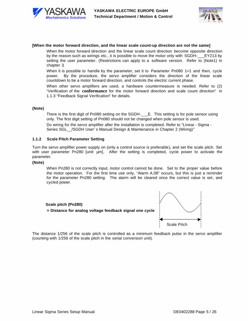
Turn the servo amplifier power supply on (only a control source is preferable), and set the scale pitch. Setwith user parameter Pn280 [unit: µm]. After the setting is completed, cycle power to activate theparameter.
(Note)When Pn280 is not correctly input, motor control cannot be done. Set to the proper value beforethe motor operation. For the first time use only, “Alarm A.08” occurs, but this is just a reminderfor the parameter Pn280 setting. The alarm will be cleared once the correct value is set, andcycled power.
The distance 1/256 of the scale pitch is controlled as a minimum feedback pulse in the servo amplifier(counting with 1/256 of the scale pitch in the serial conversion unit).
Scale pitch (Pn280) = Distance for analog voltage feedback signal one cycle
Scale Pitch

YASKAWA ELECTRIC EUROPE GmbHTechnical Department / Motion & Control
Linear Sigma Series Setup Manual DE0402288 Page 6 / 26
1.1.3 Feedback Signal Verification
Verify whether the signal from the linear scale is properly received, and the motor forward direction andlinear scale count direction are the same at the installation of 1.1.
(Note)Make sure to verify the feedback signal before the motor operation. Otherwise motor might notmove, and runaway.
(1) Verify whether the Scale Signal is Read ProperlyFirst of all, turn the servo amplifier power supply on�only a control source is preferable) and then,make the servo to Off state. Second, display the monitor Un00D (Feedback pulse monitor, Hexdisplay) with a digital operator or built-in panel operator in the state. Third, move the motor only thedistance of the arbitrary by hand. Finally, verify whether the only correct feedback pulse number isreturned.
(Example):Assume that the linear scale of scale pitch 20µm is used. When the motor is moved in the directionof 1cm count up by hand. The feedback pulse is 1cm/(20µm/256) =128000 pulse (1F400Hexpulse). So the display of Un00D should just be “H.0001”, “L.F400” (H: Upper 16 bit data, L: Lower16 bit data).
(Note):It is OK when the value is close to the above-mentioned value, since an actual display is shifted bythe error of travel distance.
����������������������������������������������������������������������������
Illustration of the above-mentioned example
When a motor is moved 1cm by hand, it is OK, if
Un00D counts only the portion.

YASKAWA ELECTRIC EUROPE GmbHTechnical Department / Motion & Control
Linear Sigma Series Setup Manual DE0402288 Page 7 / 26
[Value of Un00D is Incorrect]The following situations can be considered.
q Linear scale pitch is not suitableThe feedback pulse same as the assumed value is not returned when a set scale pitch with Pn280,and an actual scale pitch are different. Verify the scale specification.
q The linear scale is not adjustedWhen the scale is not adjusted, the output signal level goes down and proper countdown cannot bedone. Verify whether the adjustment is proper.
q The wiring between the scale serial conversion units is incorrectWhen the wiring is incorrect, proper count cannot be done. Review the wiring.
(2) Conformance verification of motor forward direction and scale count directionVerify whether the monitor Un00D is counted up when the monitor-moving coil is moved by handto the lead drawing side.
(The upper 16 bit data must increase as 1,2,3... When it is changed as FFFF, FFFE, FFFD, itmeans the value is counted down.).
[Value of UN00D is counted down]When Un00D is counted down, reverse the count direction by using one of the following methods
q Reverse the installation direction of the moving coil (Reverse the direction of the moving coil with leaddrawing exit).
q Reverse the scanning direction of the scale head.
q Replace the scale signal of the B phase + (sin) signal and B phase -(/sin) signal.
It is OK if Un00D is counted up w hen the motor is
moved in the direction of the arrow by hand.

YASKAWA ELECTRIC EUROPE GmbHTechnical Department / Motion & Control
Linear Sigma Series Setup Manual DE0402288 Page 8 / 26
(3) Verity whether the feedback with entire stroke is normalMove the moving coil of two magnets of magnet track by hand and then, verify whether the valueof monitor Un004 (Motor electrical angle monitor, Unit [°]) is returned to the original value. Alsoverify whether it becomes in the same condition with entire stroke.
(Example)Assume that the position of Un004 value before the moving coil is moved is 30. It is OK when themonitor value returns to 0 after the monitor value is counted up to 360, and it counts up to 30again at the place where two magnets is completed moving in the case of the moving coil ismoved to the motor forward direction.��������������
[Value of Un004 is not returned to the original value]The following situations can be considered
q Linear scale pitch is not suitableThe feedback pulse same as the assumed value is not returned when a set scale pitch with Pn280,and an actual scale pitch are different. Verify the scale specification.
q The linear scale is not adjustedWhen the scale is not adjusted, the output signal level goes down and proper countdown cannot bedone. Verify whether the adjustment is proper.
q The wiring between the scale serial conversion units is incorrectWhen the wiring is incorrect, proper count cannot be done. Review the wiring.
It is OK if Un004 returns to the original value when two
magnet motors are moved. Verify by all strokes.

YASKAWA ELECTRIC EUROPE GmbHTechnical Department / Motion & Control
Linear Sigma Series Setup Manual DE0402288 Page 9 / 26
1.1.4 Trial Operation by Panel Operator (Jog Mode Operation)
(Note)The trial run should be done in non-load condition as much as possible.Set the mass ratio(parameter Pn103) before the operation when the load is put on. Measure the mass by pulling themoving coil with the load by spring scale etc. (All the motor lines must be unconnected). Pn103 isobtained from the following formula.
[%]1001MassMovingMotor
Mass)CoilMovingMotor(IncludingMassLoad103)(PnRatioMass X
−=
After the verification of 1.1.2 and 1.1.3, do trial operation with the following procedure.
(1) Turn the control power and main circuit power supply on.
(2) Move the motor by operating a digital operator in the JOG mode.
Refer to the “Sigma - Series SGM_H/SGDH User' s Manual Design/Maintenance - Chapter 7.2.2"Operation by digital operator" for the operation method.
(Note)Stay away from the motor, since the motor might run away at the time of Servo ON in thebeginning.
(3) Verify whether the motor moves properly from the edge to the edge of the stroke.
[Trial operation is not done well]The following situations can be considered
q Torque reference is saturated because the load is too heavy or JOG speed is too fast.Try the torque limit parameter setting. Refer to 1.1.5. If the torque reference is still saturated, lightenthe load or slow down the Jog speed.
q Motor stops moving, after a moment movement. (1)Motor is in a reverse moving when the motor moves in reverse direction by pressing key on thepanel operator, or when the motor moves in forward direction by pressing key on the paneloperator in the Jog operation mode. Verify the motor wiring, and “Feedback Signal”(1.1.3).
q Motor stops moving, after a moment movement. (2)The scale pitch is not set correctly or scale signal is not read correctly when the motor moves inforward direction by pressing key on the panel operator, or when the motor moves in reversedirection by pressing key on the panel operator in the Jog operation mode. Verify “Scale PitchParameter Setting” (1.1.2) and “Feedback Signal”(1.1.3).
q When the motor is moved, alarm A.C2 occurs.There are possibilities that the scale signal count direction is incorrect or counting is incorrect. Verify“Feedback Signal”(1.1.3). When the counting is correctly done, it might malfunction by noise. Verifythe wiring and grounding condition of the Servo amplifier, serial conversion unit, and linear motor.

YASKAWA ELECTRIC EUROPE GmbHTechnical Department / Motion & Control
Linear Sigma Series Setup Manual DE0402288 Page 10 / 26
1.1.5 Torque Limit Parameter Setting
The factory setting of the torque limit parameter (Pn483, Pn484 Unit: [%/Rated Torque]) of SGDH isdecreased for hazard prevention for motor set up (Factory Setting: 30[%]).
When the motor moves in forward direction by pressing key on the panel operator in the Jog operationmode, increase the parameter value up to the used torque. (Increase up to the maximum value whenthere is no condition)
The setup is completed when the all above-mentioned is verified.

YASKAWA ELECTRIC EUROPE GmbHTechnical Department / Motion & Control
Linear Sigma Series Setup Manual DE0402288 Page 11 / 26
1.2 For Linear Motor without Pole Sensor
1.2.1 Installation and Wiring of Motor and Linear Scale
Install a moving coil and linear scale to make the motor forward direction, and the linear scale count-upbe in the same direction.
(Note)When a forward direction of a motor and linear scale count are not in the same direction, andwhen a motor is moved under such a condition, the motor might not move or might run away.
Motor forward direction is on a cable drawing side for the linear Sigma series motor (moving coildirection, when electric current flows into the phase in order of UVW).
An analog 1Vp-p voltage input, which is input from the linear scale to a serial exchange unit, iscounted up at A-phase (cos signal) progress
[When the direction of the motor forward, and the linear scale count-up are not in the same]q When the motor forward direction and linear scale count direction become opposite direction because
of the reason such as wirings etc., it is possible to move the motor by changing user parametersetting.
q Refer to (2) “Verification of the conformance for the motor forward direction and scale count direction”in the chapter 1.2.4 “Feedback Signal” for details.
q Do the wiring for the servo amplifier after the installation is completed. Refer to “Linear Sigma -Series SGL__/SGDH User' s Manual Design & Maintenance-Chapter 2 Wiring”
Motor Moving Coil
: Scale Count Direction
: Motor Moving Coil Forward DirectionBoth directions must be the same.
Linear Guide
Linear Guide
Motor MagnetTrack
Table
YASKAWA ELECTRIC EUROPE GmbHTechnical Department / Motion & Control
Linear Sigma Series Setup Manual DE0402288 Page 12 / 26
1.2.2 Scale Pitch Parameter Setting
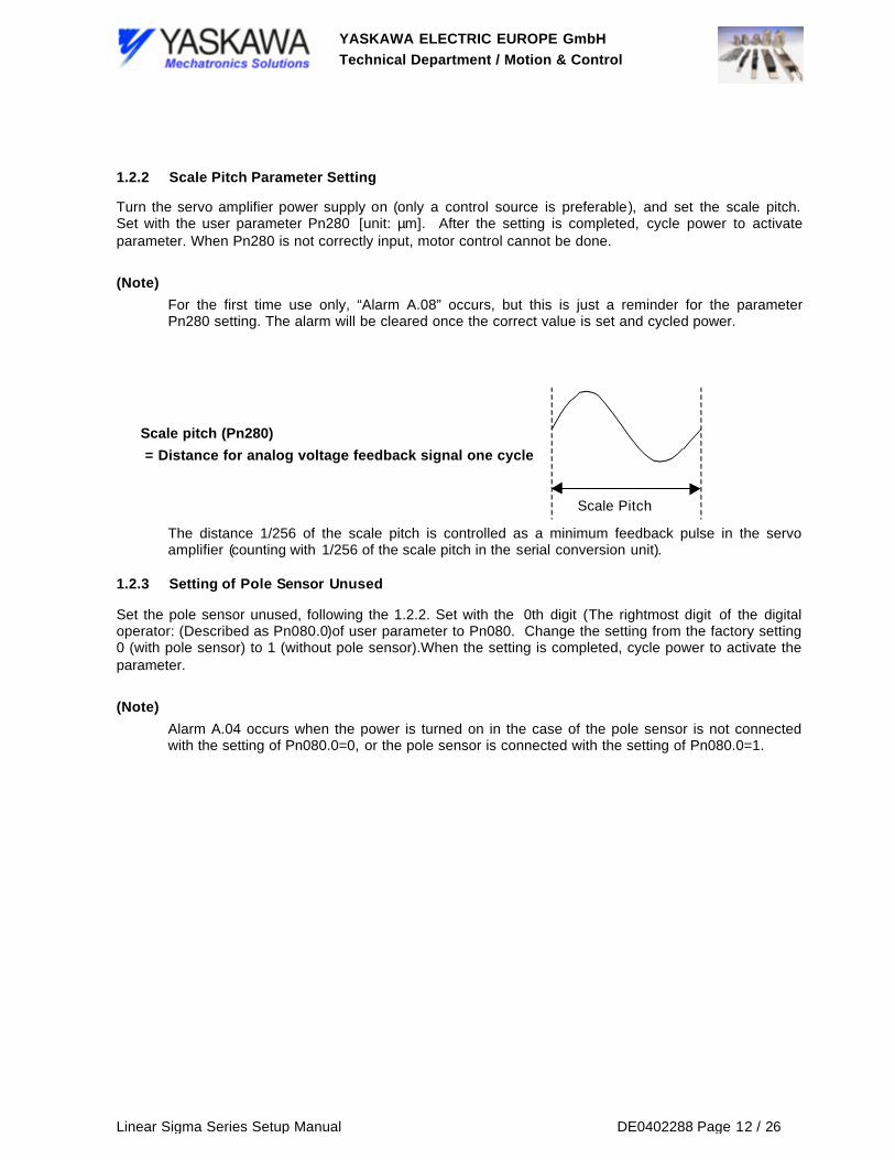
Turn the servo amplifier power supply on (only a control source is preferable), and set the scale pitch.Set with the user parameter Pn280 [unit: µm]. After the setting is completed, cycle power to activateparameter. When Pn280 is not correctly input, motor control cannot be done.
(Note)For the first time use only, “Alarm A.08” occurs, but this is just a reminder for the parameterPn280 setting. The alarm will be cleared once the correct value is set and cycled power.
The distance 1/256 of the scale pitch is controlled as a minimum feedback pulse in the servoamplifier (counting with 1/256 of the scale pitch in the serial conversion unit).
1.2.3 Setting of Pole Sensor Unused
Set the pole sensor unused, following the 1.2.2. Set with the 0th digit (The rightmost digit of the digitaloperator: (Described as Pn080.0)of user parameter to Pn080. Change the setting from the factory setting0 (with pole sensor) to 1 (without pole sensor).When the setting is completed, cycle power to activate theparameter.
(Note)Alarm A.04 occurs when the power is turned on in the case of the pole sensor is not connectedwith the setting of Pn080.0=0, or the pole sensor is connected with the setting of Pn080.0=1.
Scale pitch (Pn280) = Distance for analog voltage feedback signal one cycle
Scale Pitch

YASKAWA ELECTRIC EUROPE GmbHTechnical Department / Motion & Control
Linear Sigma Series Setup Manual DE0402288 Page 13 / 26
1.2.4 Feedback Signal Verification
Verify whether the signal from the linear scale is properly received, and motor forward direction and linearscale count direction are the same at the installation of 1.1.
(1) Scale Signal VerificationFirst of all, turn the servo amplifier power supply on�only a control source is preferable) and then,make the servo to Off state. Second, display the monitor Un00D (Feedback pulse monitor, Hexdisplay) with a digital operator or built-in panel operator in the state. Third, move the motor onlythe distance of the arbitrary by hand. Finally, verify whether the only correct feedback pulsenumber is returned.
(Example)Assume that the linear scale of scale pitch 20µm is used. When the motor is moved in thedirection of 1cm count up by hand, the feedback pulse is 1cm/(20µm/256) =128000 pulse(1F400Hex pulse). So the display of Un00D should just be “H.0001”, “L.F400” (H: Upper 16 bitdata, L: Lower 16 bit data).
(Note)It is OK when the value is close to the above-mentioned value, since an actual display is shiftedby the error of travel distance.
q Linear scale pitch is not suitableThe feedback pulse same as the assumed value is not returned when a set scale pitch with Pn280,and an actual scale pitch are different. Verify the scale specification.
q The linear scale is not adjustedWhen the scale is not adjusted, the output signal level goes down and proper countdown cannot bedone. Verify whether the adjustment is proper.
q The wiring between the scale serial conversion units is incorrectWhen the wiring is incorrect, proper count cannot be done. Review the wiring.
Illustration of the above-mentioned exampleWhen a motor is moved 1cm by hand, it is OK, if
Un00D counts only the portion.

YASKAWA ELECTRIC EUROPE GmbHTechnical Department / Motion & Control
Linear Sigma Series Setup Manual DE0402288 Page 14 / 26
(2) Conformance verification of motor forward direction and scale count directionVerify whether the monitor Un00D is counted up when the monitor-moving coil is moved by handto the lead drawing side.
(The upper 16 bit data must increase as 1,2,3... When it is changed as FFFF, FFFE, FFFD, itmeans the value is counted down.).
[Value of Un00D is counted down]When the value of Un00D is counted down, change the setting of user parameter Pn080.1. Toactivate the setting, change the factory setting Pn080.1=0 to 1,and then cycle control power. Inthis case, servo amplifier considers the direction of the linear scale countdown to be a motorforward direction and controls the electric current.
(3) Verity whether the feedback with the entire stroke is normalMove the moving coil of two magnets of magnet track by hand and then verify whether the valueof monitor Un004 (Motor electrical angle monitor, Unit [°]) goes back to the original value. Alsoverify whether it becomes in the same condition with entire stroke.
(Example)Assume that the value of Un004 at the position before the moving coil is moved is 30. It is OKwhen the monitor value returns to 0 after the monitor value is counted up to 360 and it counts upto 30 again in the place which it completed moving by two magnets in the case of the moving coilis moved to the motor forward direction.
It is OK if Un00D is counted up w hen the motor is
moved in the direction of the arrow by hand.
It is OK if Un004 returns to the original value when twomagnet motors are moved. Verify by all strokes.

YASKAWA ELECTRIC EUROPE GmbHTechnical Department / Motion & Control
Linear Sigma Series Setup Manual DE0402288 Page 15 / 26
[Value of Un004 is not returned to the original value]The following situations can be considered
q Linear scale pitch is not suitableThe feedback pulse the same as the assumed value is not returned when a scale pitch set withPn280 and an actual scale pitch are different. Verify the scale specification.
q The linear scale is not adjustedWhen the sale is not adjusted, the output signal level goes down and proper countdown cannot bedone. Verify whether the adjustment is proper.
q The wiring between the scale cereal conversion units is incorrectWhen the wiring is incorrect, a proper count cannot be done. Review the wiring.
1.2.5 Magnetic Pole Detection Start Signal/P-DET Setting of Input Allocation
For the linear motor without a pole sensor, it is necessary to detect the magnetic pole after the powersupply is turned on.
When the input signal allocation mode is a factory setting (SGDB compatible mode, Pn50A.0=0), themagnetic pole detection is begun synchronizing with the servo ON (/S-ON) signal and the servo ready(/S-RDY) signal is turned on at the same time with detection's ending.
When the servo ready signal is observed and the sequence of the servo on signal output is united by thehost controller or to detect the magnetic pole according to timing different from the servo on signal, it isnecessary to allocate the magnetic pole detection start signal (/P-DET) to the arbitrary input terminal.
After it is set as user parameter Pn50A.0=1(input signal allocation is freely settable), allocate /P-DETsignal to the arbitrary input terminal by Pn50D.3. After completing the allocation, cycle power to activatethe parameter.
1.2.6 Mass Ratio Setting
Set the mass ratio (parameter Pn103) before the magnetic pole detecting operation. Measure the massby pulling the moving coil with the load by spring scale etc. (all motor lines must be unconnected).
Pn103 is obtained from the following formula.
[%]1001MassMovingMotor
Mass)CoilMovingMotor(IncludingMassLoad103)(PnRatioMass X
−=

YASKAWA ELECTRIC EUROPE GmbHTechnical Department / Motion & Control
Linear Sigma Series Setup Manual DE0402288 Page 16 / 26
1.2.7 Over Travel Signal Setting
When it is in over-travel state, the magnetic pole detection cannot be begun. Connect the signalconductor and put it into the base block state when the over-travel function is used. Set the userparameter to Pn50A.3=8, Pn50B.0=8(OT signal is invalid) when the over-travel function is not used. Thencycle power.
1.2.8 Torque Limit Parameter Setting
The factory setting of the torque limit parameter (Pn483, Pn484 Unit: [%/Rated Torque]) for SGDH isreduced for hazard prevention for motor set up (Factory Setting: 30[%]).
The motor does not runaway after the setting completion of the scale pitch parameter and the verificationcompletion of the feedback signal. So increase the parameter value up to the used torque. (Increase upto the maximum value when there is no condition) The magnetic pole detection might not operateproperly when the limitation is too much.
1.2.9 Verification of Magnetic Pole Detecting Operation
Verify whether the magnetic pole detection is done properly.
After inputting both control sources and main circuit power supply, input /S-ON signal (When themagnetic pole detection start signal is used: /P-DET signal) and then detect the magnetic pole.
When the operator display is “bb” at power supply is turned on, it displays “Pdt” while detecting themagnetic pole and it returns to “bb” when the detection is completed.
(Note)While detecting the magnetic pole, current flows to the motor. Be careful with an electric shock.
Moreover, stay away from the motor since the motor might move greatly while detecting.
After the detection is completed, verify the electrical angle with monitor Un004 by pressing the motoragainst the stroke end. After the verification, separate the motor from the stroke end some degree (It ispreferable to separate by 10mm or more). Then detect the magnetic pole gain after cycling power.
As for the magnetic pole detection, if the gap of the electrical angle is within ±10°, in a repeated operationof three times or more, this detection is appropriate.
[Magnetic pole detection is not performed properly]The following situation can be considered.
q Magnetic pole detection speed loop gain parameter (Pn481) is small.Enlarge Pn481 setting when the electrical angle is greatly different every time and when it is hard totell whether the detected motor is moving in the performance of the magnetic pole detection.
q Used scale resolution is too rough.It is effective to increase the used scale resolution when alarm A.C5 occurs while the magnetic poledetection. The minimum pulse resolution should be 5µm or less (scale pitch is 1.28mm or less) forSGDH. The magnetic pole can surely be detected when the minimum resolution is 1µm or less.Consult a technical engineer when a scale is larger than above-mentioned since the adjustment ofthe magnetic pole detection is needed.
q The linear scale signal cannot be read properlyGo through the set up procedure of 1.2.2, 1.2.3, and 1.2.4. Then verify whether the scale andparameter are set properly.
It is necessary to adjust the parameter for the magnetic pole detection when the magnetic pole detectionis not performed properly even if the above-mentioned countermeasure is done. Because the parameterfor the magnetic pole detection is being kept in the system parameter excluding the speed loop gain and

YASKAWA ELECTRIC EUROPE GmbHTechnical Department / Motion & Control
Linear Sigma Series Setup Manual DE0402288 Page 17 / 26
the speed loop integral time constant for SGDH, the user cannot adjust the parameter. Consult atechnical engineer when adjustment is needed.
1.2.10 Trial Operation by Panel Operator (JOG Mode Operation)
After the verification from 1.2.1 through 1.2.9, do trial operation using the following procedures.
(Note)Do the Trial Operation with Non-Load as Much as Possible.
(1) Turn the control power and main circuit power supply on.
(2) Move the motor by operating a digital operator in the JOG mode.
Refer to the “Σ -II Series SGM_H/SGDH User' s Manual Design & Maintenance-Chapter7.2.2 Operation by digital operator” for the operation method.
(Note)Stay away from the motor, since the motor might run away at the time of Servo ON in thebeginning.
(3) Verify whether the motor moves properly from the edge to the edge of the stroke.
[Trial operation is not done well]The following situations can be considered
q Torque reference is saturated because the load is too heavy or JOG speed is too fast.Lighten the load or slow down the Jog speed.
q Motor stops moving, after a moment movement. (1)Motor is in a reverse moving when the motor moves in reverse direction by pressing key on thepanel operator, or when the motor moves in forward direction by pressing key on the paneloperator in the Jog operation mode. Verify the motor wiring and “Feedback Signal Verification”(1.2.4).
q Motor stops moving, after a moment movement. (2)The scale pitch is not set correctly or scale signal is not read correctly when the motor moves inforward direction by pressing key on the panel operator, or when the motor moves in reversedirection by pressing key on the panel operator in the Jog operation mode. Verify “Scale PitchParameter Setting” (1.2.2) and “Feedback Signal” (1.2.4).
q When the motor is moved, alarm A.C2 occurs.There is a possibility that the Feedback count is incorrect. Verify “Feedback Signal” (1.2.4). When thecounting is done correctly, it might malfunction by noise. Verify the wiring and grounding condition ofthe Servo amplifier, serial conversion unit, and linear motor.
The setup is completed when the all above-mentioned is verified.

YASKAWA ELECTRIC EUROPE GmbHTechnical Department / Motion & Control
Linear Sigma Series Setup Manual DE0402288 Page 18 / 26
2 SGDD Type Servo Amplifier Setup Procedure
2.1 Motor and Li1near Scale Installation and Wiring
Install a moving coil and linear scale to make the motor forward direction, and the linear scale count-upbe in the same direction.
(Note)When a forward direction of a motor and linear scale count are not in the same direction, andwhen a motor is moved under such a condition, the motor might not move or might run away.
Motor forward direction is on a cable drawing side for the linear Σ series motor (moving coildirection, when electric current flows into the phase in order of UVW).
The 90° phase differential two-phase pulse train input, which is input from the linear scale to theservo amplifier is counted up at B phase progress.
[When the direction of the motor forward, and the linear scale count-up are not in the same]
When the motor forward direction and linear scale count direction become opposite direction because ofthe reason such as wirings etc., it is possible to move the motor by changing user parameter setting.
Refer to (2) “Verification of the conformance for the motor forward direction and scale count direction” inthe chapter 1.2.3 “Feedback Signal” for details.
Do the wiring for the servo amplifier after the installation is completed. Refer to “Linear Σ -II SeriesSGL__/SGDH User' s Manual Design & Maintenance-Chapter 2 Wiring”
Scale Head
Motor Moving Coil
: Scale Count Direction
: Motor Moving Coil Forward DirectionBoth directions must be the same.
Linear Guide
Linear Guide
Motor MagnetTrack
Table

YASKAWA ELECTRIC EUROPE GmbHTechnical Department / Motion & Control
Linear Sigma Series Setup Manual DE0402288 Page 19 / 26
2.2 Linear Encoder Resolution (before quadrature) Setting
Turn the servo amplifier power supply on (only a control source is preferable), and set the linear encoderresolution (before quadature). Set with the user parameter Pn280 [unit: 0.01µm]. After the setting iscompleted, cycle power to activate the parameter. When Pn209 is not correctly input, motor controlcannot be done.
(Note)For the first time use only, “Alarm A.08” occurs, but this is just a reminder for the parameterPn209 setting. The alarm will be cleared once the correct value is set and cycled power.
The distance 1/4 of the linear encoder resolution (Pn209) is controlled as a minimum feedbackpulse in the servo amplifier.
Setting Procedure:Set the distance between rising edges of thephase in the one side of 90° phasedifferential two-phase pulse train feedbacksignal.
Pn209
A Phase
B Phase
Scale pitch (Pn280) = Distance for analog voltage feedback signalone cycle
Scale Pitch

YASKAWA ELECTRIC EUROPE GmbHTechnical Department / Motion & Control
Linear Sigma Series Setup Manual DE0402288 Page 20 / 26
2.3 Feedback Signal Verification
Verify whether the signal from the linear scale is properly received, and motor forward direction and linearscale count direction are the same at the installation of 1.1.
(1) Scale Signal VerificationFirst of all, turn the servo amplifier power supply on�only a control source is preferable) and then, makethe servo to Off state. Second, display the monitor Un00D (Feedback pulse monitor, Hex display) with adigital operator or built-in panel operator in the state. Third, move the motor only the distance of thearbitrary by hand. Finally, verify whether the only correct feedback pulse number is returned.
(Example)Assume that the linear scale of 1µm liner encoder resolution (Assume that the setting isparameter Pn209 = 400: resolution after quadrature) is used.
When the motor is moved in the direction of 1cm count up by hand, the feedback pulse is1cm/1µm=10000 pulse (2710 Hex pulse). So the display of Un00D should just be “H.0000",“L.2710" (H: Upper 16 bit data, L: Lower 16 bit data)
(Note)It is OK when the value is close to the above-mentioned value, since an actual display is shiftedby the error of travel distance.
����������������������������������������������������������������������������
[Value of Un00D is incorrect]The following situations can be considered
q Linear scale resolution setting is not suitableWhen the linear encoder resolution and the actual scale resolution set by Pn209 are different, theassumed feedback pulse value is not returned. Verify the scale specification.
q The linear scale is not adjustedWhen the sale is not adjusted, the output signal level goes down and proper countdown cannot bedone. Verify whether the adjustment is proper.
q The wirings between the scale servo amplifier are incorrectWhen the wiring is incorrect, a proper count cannot be done. Review the wiring.
Illustration of the above-mentioned example
When a motor is moved 1cm by hand, it is OK, if
Un00D counts only the portion.
YASKAWA ELECTRIC EUROPE GmbHTechnical Department / Motion & Control
Linear Sigma Series Setup Manual DE0402288 Page 21 / 26
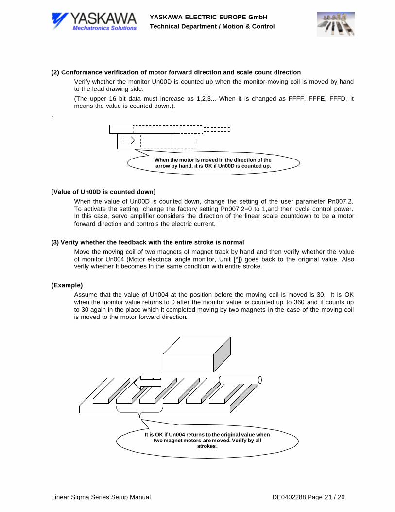
(2) Conformance verification of motor forward direction and scale count directionVerify whether the monitor Un00D is counted up when the monitor-moving coil is moved by handto the lead drawing side.
(The upper 16 bit data must increase as 1,2,3... When it is changed as FFFF, FFFE, FFFD, itmeans the value is counted down.).
.
[Value of Un00D is counted down]When the value of Un00D is counted down, change the setting of the user parameter Pn007.2.To activate the setting, change the factory setting Pn007.2=0 to 1,and then cycle control power.In this case, servo amplifier considers the direction of the linear scale countdown to be a motorforward direction and controls the electric current.
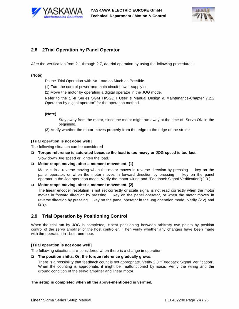
(3) Verity whether the feedback with the entire stroke is normalMove the moving coil of two magnets of magnet track by hand and then verify whether the valueof monitor Un004 (Motor electrical angle monitor, Unit [°]) goes back to the original value. Alsoverify whether it becomes in the same condition with entire stroke.
(Example)Assume that the value of Un004 at the position before the moving coil is moved is 30. It is OKwhen the monitor value returns to 0 after the monitor value is counted up to 360 and it counts upto 30 again in the place which it completed moving by two magnets in the case of the moving coilis moved to the motor forward direction.
When the motor is moved in the direction of thearrow by hand, it is OK if Un00D is counted up.
It is OK if Un004 returns to the original value whentwo magnet motors are moved. Verify by all
strokes.

YASKAWA ELECTRIC EUROPE GmbHTechnical Department / Motion & Control
Linear Sigma Series Setup Manual DE0402288 Page 22 / 26
[Value of Un004 is not returned to the original value]The following situations can be considered
q Linear scale resolution setting is not suitableWhen the linear encoder resolution and the actual scale resolution set by Pn209 is different, theassumed feedback pulse value is not returned. Verify the scale specification.
q The linear scale is not adjustedWhen the sale is not adjusted, the output signal level goes down and proper countdown cannot bedone. Verify whether the adjustment is proper.
q The wiring between the scale cereal conversion units is incorrectWhen the wiring is incorrect, a proper count cannot be done. Review the wiring.
2.4 Setting of Magnetic Pole Detection Beginning Timing
For linear motor without the pole sensor, it is necessary to detect the magnetic pole after the powersupply is turned on.
For the SGDD type servo amplifier, magnetic pole detection start signal /M is allocated to I1 (CN1-41) atshipping. /M-SET signal needs to be provided to use as it is.
When /M-SET signal is not used, set the user parameter to Pn007.0=1 and then, cycle power. As aresult, the magnetic pole detection is done synchronizing with the servo on signal (/S-ON).
2.5 Mass Ratio Setting
Set the mass ratio (parameter Pn103) before the magnetic pole detecting operation. Measure the massby pulling the moving coil with the load by spring scale etc. (all motor lines must be unconnected).
Pn103 is obtained from the following formula.
[%]1001MassMovingMotor
Mass)CoilMovingMotor(IncludingMassLoad103)(PnRatioMass X
−=
2.6 Over Travel Signal Setting
When it is in over-travel state, the magnetic pole detection cannot be begun. Connect the signalconductor and put it into the base block state when the over-travel function is used. Set the userparameter to Pn50A.3=8, Pn50B.0=8(OT signal is invalid) when the over-travel function is not used. Thencycle power.
Moreover, detecting the magnetic pole regardless of the over travel signal state, set to Pn007.3=1 (Beforecompleting the magnetic pole detection, the OT mask should be done) and then, cycle power.

YASKAWA ELECTRIC EUROPE GmbHTechnical Department / Motion & Control
Linear Sigma Series Setup Manual DE0402288 Page 23 / 26
2.7 Verification of Magnetic Pole Detection
Verify whether the magnetic pole detection is done properly. After inputting both control source and maincircuit power supply, input /MSET signal (/S-ON when the setting is Pn007.0=1) and then detect themagnetic pole.
(Note)While detecting the magnetic pole, current flows to the motor. Be careful with an electric shock.Moreover, stay away from the motor since the motor might move greatly while detecting.
After the detection is completed, verify the electrical angle with monitor Un004 by pressing the motoragainst the stroke end. After the verification, separate the motor from the stroke end some degree (It ispreferable to separate by 10mm or more). Then detect the magnetic pole gain after cycling power.
As for the magnetic pole detection, if the gap of the electrical angle is within ±10°, in a repeated operationof three times or more, this detection is appropriate.
[Magnetic pole detection is not performed properly]The following situation can be considered.
q Magnetic pole detection speed loop gain parameter (Pn413) is small.Enlarge Pn413 setting when the electrical angle is greatly different every time and when it is hard totell whether the detected motor is moving in the performance of the magnetic pole detection.
q Used scale resolution is too rough.It is effective to increase the used scale resolution when alarm A.C5 occurs while the magnetic poledetection. The minimum pulse resolution should be 5�m or less (Pn209=2000 or less) for SGDD.The magnetic pole can surely be detected when the minimum resolution is 1�m or less. Consult atechnical engineer when a scale is larger than above-mentioned since the adjustment of the magneticpole detection is needed.
q The linear scale signal cannot be read properlyGo through the set up procedure of 2.2, 2.3. Then verify whether the scale and parameter are setproperly.
It is necessary to adjust the parameter for the magnetic pole detection when the magnetic pole detectionis not performed properly even if the above-mentioned countermeasure is done. Consult the technicalengineer when the adjustment is needed.
YASKAWA ELECTRIC EUROPE GmbHTechnical Department / Motion & Control
Linear Sigma Series Setup Manual DE0402288 Page 24 / 26
2.8 2Trial Operation by Panel Operator
After the verification from 2.1 through 2.7, do trial operation by using the following procedures.
(Note)Do the Trial Operation with No-Load as Much as Possible.
(1) Turn the control power and main circuit power supply on.
(2) Move the motor by operating a digital operator in the JOG mode.
Refer to the “Σ -II Series SGM_H/SGDH User' s Manual Design & Maintenance-Chapter 7.2.2Operation by digital operator” for the operation method.
(Note)Stay away from the motor, since the motor might run away at the time of Servo ON in thebeginning.
(3) Verify whether the motor moves properly from the edge to the edge of the stroke.
[Trial operation is not done well]The following situation can be considered
q Torque reference is saturated because the load is too heavy or JOG speed is too fast.Slow down Jog speed or lighten the load.
q Motor stops moving, after a moment movement. (1)
Motor is in a reverse moving when the motor moves in reverse direction by pressing key on thepanel operator, or when the motor moves in forward direction by pressing key on the paneloperator in the Jog operation mode. Verify the motor wiring and “Feedback Signal Verification”(2.3.)
q Motor stops moving, after a moment movement. (2)The linear encoder resolution is not set correctly or scale signal is not read correctly when the motormoves in forward direction by pressing key on the panel operator, or when the motor moves inreverse direction by pressing key on the panel operator in the Jog operation mode. Verify (2.2) and(2.3).
2.9 Trial Operation by Positioning Control
When the trial run by JOG is completed, repeat positioning between arbitrary two points by positioncontrol of the servo amplifier or the host controller. Then verify whether any changes have been madewith the operation in about one hour.
[Trial operation is not done well]The following situations are considered when there is a change in operation.
q The position shifts. Or, the torque reference gradually grows.There is a possibility that feedback count is not appropriate. Verify 2.3 “Feedback Signal Verification”.When the counting is appropriate, it might be malfunctioned by noise. Verify the wiring and theground condition of the servo amplifier and linear motor.
The setup is completed when all the above-mentioned is verified.

YASKAWA ELECTRIC EUROPE GmbHTechnical Department / Motion & Control
Linear Sigma Series Setup Manual DE0402288 Page 25 / 26
3 Difference from SGDH-___EY213
SGDH-___EY213 is a servo amplifier dedicated for the linear, which has improved features andperformances of SGDH-___E. The following features are different from SGDH-___E.
3.1 Motor Peak Speed Setting
Motor peak speed can be set by user parameter for Y213. Pn384: Motor Peak Speed [Unit: 100mm/s]
It is possible to increase the speed control resolution by decreasing the parameter value. The speedripple and stop accuracy performance might be improved by increasing the speed control resolution.
3.2 Current Commutation Direction Setting of Motor with Pole Sensor (Note 1)
Set the user parameter to Pn080.1=1 when a motor forward direction and linear scale count up directionwith pole sensor are opposite for Y213. The change in the direction of the motor current commutation andthe pole sensor signal matched to it are processed.
With the setting change, it is possible to control the motor properly even though the motor forwarddirection with pole sensor and scale count up direction are opposite.
3.3 Error Detection of Frequency Dividing Output Setting (Note 1)
Alarm A.09 occurs for Y213 when the setting for frequency dividing output exceeds the limit(Max.12.8MHz).
Also, the setting value that the frequency does not exceed the limit is displayed in the monitor modeUn010. Since the frequency of the frequency dividing output is adjusted by either parameter in the PGdividing ratio (Pn281) or motor peak speed (Pn384), limit value display can be chosen by user parameterPn080.3 on the monitor Un010.
3.4 Pole Sensor Signal Monitor (Note 1)
Pole sensor signal is monitored in the monitor mode Un011 in Y213 It is effective for the trouble shootingat the setup.
(Note)Applied to the software of base version 14 or later version, and revised version 9 of base version13.

YASKAWA ELECTRIC EUROPE GmbHTechnical Department / Motion & Control
Linear Sigma Series Setup Manual DE0402288 Page 26 / 26
4 Electric Gear Ratio Setting Method
4.1 For the SGDH Type Servo Amplifier
Electric gear ratio for the SGDH type servo amplifier can be obtained from the following formula.
[ ]Pn203Pn202
256Pn280
ìm/pulsePulseReference ×=
(Example)Making the travel distance per 1 pulse reference to 1µm, when the linear scale of scale pitch 20µm isused.
[ ] [ ]ìm/pulse1Pn203Pn202
256ìm20 =×
564
20256
Pn203Pn202 ==∴
Therefore, set as Pn202=64, Pn203=5.
4.2 For the SGDD Type Servo Amplifier
Electric gear ratio for the SGDD type servo amplifier can be obtained from the following formula.
[ ]Pn203Pn202
400Pn209
ìm/pulsePulseReference ×=
(Example)Making the travel distance per 1 pulse reference to 10µm, when the linear scale of scaleresolution 0.5µm is used.
[ ]ìm/pulse10Pn203Pn202
400200 =×
20200
10400Pn203Pn202 =×=∴
Therefore, set as Pn202=20, Pn203=1.