Linear Luminaire for Fluorescent Lamps · 2018-09-13 · 10.2 Returning the device ... EN EN EN EN...
22
EN EN EN EN EN EN EN EN EN EN EN EN EN EN EN EN EN EN EN EN EN EN EN EN EN Operating instructions EN Linear Luminaire for Fluorescent Lamps Series ATEX-HALP
Transcript of Linear Luminaire for Fluorescent Lamps · 2018-09-13 · 10.2 Returning the device ... EN EN EN EN...

ENENENENENENENENENENENENENENENENEN
Operating instructions
EN
ENENENENENENENEN
Linear Luminaire for Fluorescent Lamps
Series ATEX-HALP

General InformationENENENENENENENENENENENENENENENENENENENENENENENENEN
Contents1 General Information ............................................................................................21.1 Manufacturer .......................................................................................................21.2 Information regarding the operating instructions .................................................31.3 Conformity with standards and regulations .........................................................32 Explanation of the symbols .................................................................................32.1 Symbols in these operating instructions .............................................................32.2 Warning notes .....................................................................................................32.3 Symbols on the device ........................................................................................43 Safety notes ........................................................................................................43.1 Operating instructions storage ............................................................................43.2 Safe use ..............................................................................................................43.3 Intended Use .......................................................................................................53.4 Modifications and alterations ..............................................................................54 Function and device design ................................................................................54.1 Function ..............................................................................................................54.2 Device design .....................................................................................................65 Technical data .....................................................................................................66 Transport and storage .......................................................................................107 Mounting and installation ..................................................................................107.1 Dimensions / fastening dimensions ..................................................................107.2 Mounting / dismounting, operating position ......................................................127.3 Installation .........................................................................................................168 Commissioning .................................................................................................199 Operation ..........................................................................................................199.1 Troubleshooting ................................................................................................1910 Maintenance and repair ....................................................................................2010.1 Maintenance .....................................................................................................2010.2 Returning the device .........................................................................................2211 Disposal ............................................................................................................2212 Accessories and Spare parts ...........................................................................22
1 General Information
1.1 ManufacturerLarson Electronics 9419 US-HWY 175 Kemp, TX 75143
Phone:Fax:Internet:E-mail:
800-369-6671903-498-3364 www.larsonelectronics.com [email protected]
2 ATEX-HALP SERIES
Explanation of the symbols ENENENENENENENENENENENENENENENENENENENENENENENENEN
1.2 Information regarding the operating instructions180809 / ATEX-HALPID-No.:
The original instructions are the English edition.
1.3 Conformity with standards and regulationsSee certificates and EC Declaration of Conformity.The device has IECEx approval. See IECEx homepage: http://iecex.iec.ch/Further national certificates can be downloaded via the following link: https://www.larsonelectronics.com under part number.
2 Explanation of the symbols
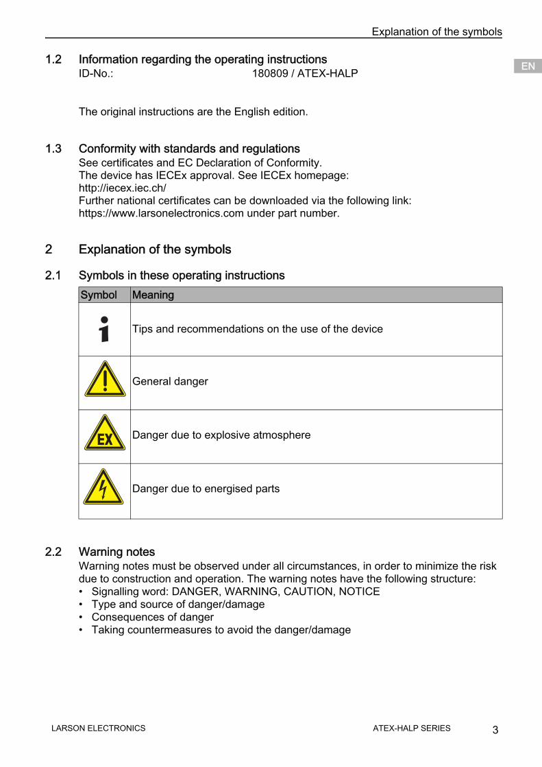
2.1 Symbols in these operating instructions
2.2 Warning notesWarning notes must be observed under all circumstances, in order to minimize the risk due to construction and operation. The warning notes have the following structure:• Signalling word: DANGER, WARNING, CAUTION, NOTICE• Type and source of danger/damage• Consequences of danger• Taking countermeasures to avoid the danger/damage
Symbol Meaning
Tips and recommendations on the use of the device
General danger
Danger due to explosive atmosphere
Danger due to energised parts
LARSON ELECTRONICS 3ATEX-HALP SERIES

Safety notesENENENENENENENENENENENENENENENENENENENENENENENENEN
2.3 Symbols on the device
3 Safety notes
3.1 Operating instructions storage• Read the operating instructions carefully and store them at the mounting location of
the device.• Observe applicable documents and operating instructions of the devices to be
connected.
3.2 Safe use• Read and observe the safety notes in these operating instructions!• Observe characteristic values and rated operating conditions on the rating and data
plates!• Observe additional information plates on the device!• Use the device in accordance with its intended and approved purpose only!• We cannot be held liable for damage caused by incorrect or unauthorized use or by
non-compliance with these operating instructions.• Before installation and commissioning, make sure that the device is not damaged!• Work on the device (installation, maintenance, overhaul, repair) may only be carried
out by appropriately authorized and trained personnel.
DANGERDanger to personsNon-compliance with the instruction results in severe or fatal injuries to persons.
WARNINGDanger to personsNon-compliance with the instruction can result in severe or fatal injuries to persons.
CAUTIONDanger to personsNon-compliance with the instruction can result in light injuries to persons.
NOTICEAvoiding material damageNon-compliance with the instruction can result in material damage to the device and / or its environment.
Symbol MeaningCE marking according to the currently applicable directive.
According to marking, device approved for hazardous areas.
4 LARSON ELECTRONICSATEX-HALP SERIES
Function and device design ENENENENENENENENENENENENENENENENENENENENENENENENEN
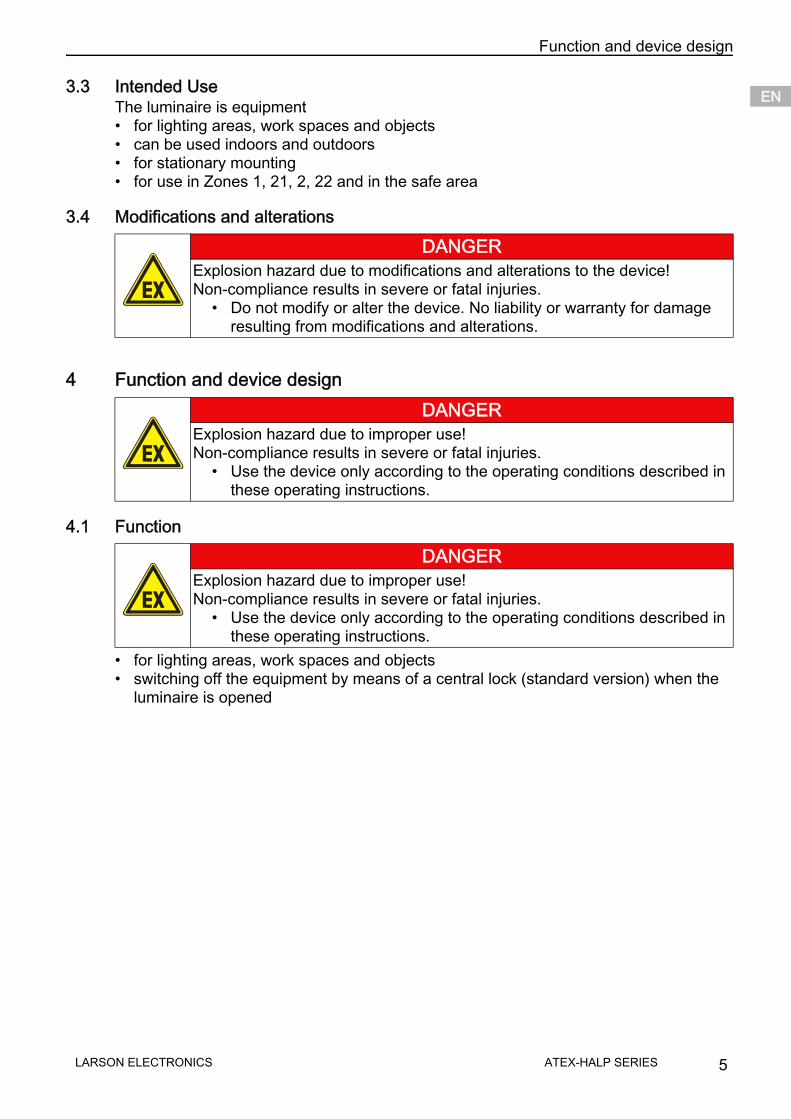
3.3 Intended UseThe luminaire is equipment• for lighting areas, work spaces and objects• can be used indoors and outdoors• for stationary mounting• for use in Zones 1, 21, 2, 22 and in the safe area
3.4 Modifications and alterations
4 Function and device design
4.1 Function
• for lighting areas, work spaces and objects• switching off the equipment by means of a central lock (standard version) when the
luminaire is opened
DANGERExplosion hazard due to modifications and alterations to the device! Non-compliance results in severe or fatal injuries.
• Do not modify or alter the device. No liability or warranty for damageresulting from modifications and alterations.
DANGERExplosion hazard due to improper use!Non-compliance results in severe or fatal injuries.
• Use the device only according to the operating conditions described inthese operating instructions.
DANGERExplosion hazard due to improper use!Non-compliance results in severe or fatal injuries.
• Use the device only according to the operating conditions described inthese operating instructions.
LARSON ELECTRONICS 5ATEX-HALP SERIES
Technical dataENENENENENENENENENENENENENENENENENENENENENENENENEN
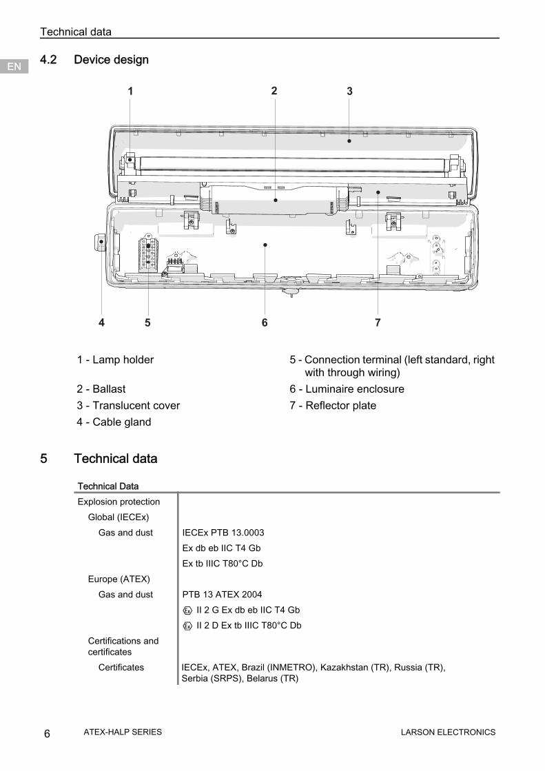
4.2 Device design
5 Technical data
1 - Lamp holder 5 - Connection terminal (left standard, right with through wiring)
2 - Ballast 6 - Luminaire enclosure3 - Translucent cover 7 - Reflector plate4 - Cable gland
Technical DataExplosion protection
Global (IECEx)Gas and dust IECEx PTB 13.0003
Ex db eb IIC T4 Gb Ex tb IIIC T80°C Db
Europe (ATEX)Gas and dust PTB 13 ATEX 2004
E II 2 G Ex db eb IIC T4 Gb E II 2 D Ex tb IIIC T80°C Db
Certifications and certificates
Certificates IECEx, ATEX, Brazil (INMETRO), Kazakhstan (TR), Russia (TR), Serbia (SRPS), Belarus (TR)
1 2
4
3
5 6 7
6 LARSON ELECTRONICSATEX-HALP SERIES

Technical data ENENENENENENENENENENENENENENENENENENENENENENENENEN
Electrical dataBallast
Power factor cos p cos p ) 0.97 capacitive; no additional compensation required
Technical Data
Lamp start Cold startVoltageVoltage DC during switching on
220 ... 240 V AC198 … 264 V DC
Voltage DC during operation
176 … 264 V DC
Frequency 0 / 50 … 60 HzOperation of the lamps DC
1 lamp
Lamp standard
IEC 60081
Lamp power 18, 36, 58 WNominal current
1 x 18 W, 85 mA2 x 18 W, 170 mA1 x 36 W, 160 mA2 x 36 W, 320 mA1 x 58 W, 250 mA2 x 58 W, 500 mA
LARSON ELECTRONICS 7ATEX-HALP SERIES
Technical dataENENENENENENENENENENENENENENENENENENENENENENENENEN
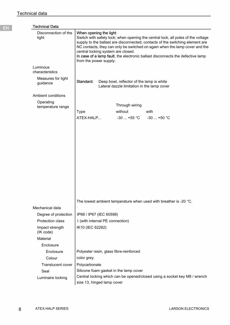
Disconnection of the light
When opening the light Switch with safety lock; when opening the central lock, all poles of the voltage supply to the ballast are disconnected; contacts of the switching element are NC contacts, they can only be switched on again when the lamp cover and the central locking system are closed. In case of a lamp fault, the electronic ballast disconnects the defective lamp from the power supply.
Luminous characteristics
Measures for light guidance
Ambient conditionsOperating temperature range
The lowest ambient temperature when used with breather is -20 °C.Mechanical data
Degree of protection IP66 / IP67 (IEC 60598)Protection class I (with internal PE connection)Impact strength (IK code)
IK10 (IEC 62262)
MaterialEnclosure
EnclosureColour
Polyester resin, glass fibre-reinforced color grey.
Translucent coverSeal
Luminaire locking
PolycarbonateSilicone foam gasket in the lamp coverCentral locking which can be opened/closed using a socket key M8 / wrench size 13, hinged lamp cover
Technical Data
Standard: Deep bowl, reflector of the lamp is whiteLateral dazzle limitation in the lamp cover
Through wiringType without withATEX-HALP... -30 ... +55 °C -30 ... +50 °C
8 LARSON ELECTRONICSATEX-HALP SERIES

Technical data ENENENENENENENENENENENENENENENENENENENENENENENENEN
Montage / InstallationCable glands
Connection
Through wiring
Assembly
Technical Data
Standard luminairePlastic: 2 x M25 x 1.5 cable gland 8161 and
1 x M25 x 1.5 stopping plugs 8290 (enclosed)Metal: 2 x metal plates M20 x 1.5 connected by means of PE for metal
cable entriesAttention: cable entries must be ordered separately
Special: max. 4 bores for M20, M25, NPSM ½’’max. 2 bores for NPT ¾’’Metal cable glands: M20 x 1.5, M25 x 1.5; earthing of the metal
cable entries by means of metal plates
Standard: Spring clamp terminals5-pole: L1, L2, L3, N, PEClamping range: 1 x 0.75 ... 4 mm2 (solid / finely stranded)4 mm2 finely stranded without core end sleeve only (2 free clamping units for each pole available)
Special: Terminal block with covering 5-pole: L1, L2, L3, N, PEClamping range: 2 x 1.5 ... 6 mm2 (solid); 2 x 1.5 ... 4 mm2 (finely and extra finely stranded)
Through wiring Standard luminaire Luminaires are equipped with internal through wiring. Ingoing and outgoing leads can be connected on the opposite sides. Terminals: see Techn. data Wiring cross-section: 2.5 mm2 for max. 16 A
without Optional On the connection side, there are 2 bores M25 x 1.5 for cable entries for ingoing and outgoing wiring of the connection line (ingoing and outgoing leads on one side).
For outdoor mounting, a breather is recommendedStandard luminaireStandard: 2 x M8 insert nuts in the enclosureSpecial: Mounting grooves in the enclosure for the use of fastening and
ceiling rails for variable luminaire mounting (variable mounting distances for luminaires 18 W: 320 ... 480 mm; 36 W / 58 W: 670 ... 930 mm)
LARSON ELECTRONICS 9ATEX-HALP SERIES
Transport and storageENENENENENENENENENENENENENENENENENENENENENENENENEN
6 Transport and storage• Transport and store the device only in the original packaging.• Store the device in a dry place (no condensation) and vibration-free.• Do not drop the device.
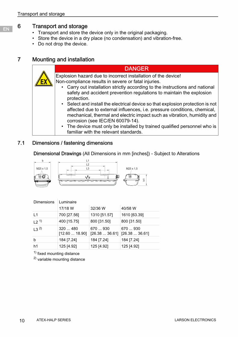
7 Mounting and installation
7.1 Dimensions / fastening dimensions
DANGERExplosion hazard due to incorrect installation of the device! Non-compliance results in severe or fatal injuries.
• Carry out installation strictly according to the instructions and nationalsafety and accident prevention regulations to maintain the explosion protection.
• Select and install the electrical device so that explosion protection is notaffected due to external influences, i.e. pressure conditions, chemical, mechanical, thermal and electric impact such as vibration, humidity and corrosion (see IEC/EN 60079-14).
• The device must only be installed by trained qualified personnel who isfamiliar with the relevant standards.
Dimensional Drawings (All Dimensions in mm [inches]) - Subject to Alterations
M25 x 1,5 L3 M25 x 1,5
L2
L1b
h1
Dimensions Luminaire17/18 W 32/36 W 40/58 W
L1 700 [27.56] 1310 [51.57] 1610 [63.39]
L2 1) 400 [15.75] 800 [31.50] 800 [31.50]
L3 2) 320 ... 480 [12.60 ... 18.90]
670 ... 930 [26.38 ... 36.61]
670 ... 930 [26.38 ... 36.61]
b 184 [7.24] 184 [7.24] 184 [7.24]h1 125 [4.92] 125 [4.92] 125 [4.92]1) fixed mounting distance2) variable mounting distance
10 LARSON ELECTRONICSATEX-HALP SERIES
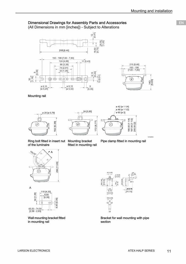
Mounting and installation ENENENENENENENENENENENENENENENENENENENENENENENENEN
Dimensional Drawings for Assembly Parts and Accessories (All Dimensions in mm [inches]) - Subject to Alterations
Mounting rail
15783E00
Ring bolt fitted in insert nut of the luminaire
Mounting bracket fitted in mounting rail
Pipe clamp fitted in mounting rail
Wall mounting bracket fitted in mounting rail
Bracket for wall mounting with pipe section
9
30
9
6,1
0
ø 8,10
32 [1,26]
12
[,
]0 4
718,5
0
[,
]0 7
3
30,5
0
[,
]1 2
0
74 [ , ]2 91
86 [ , ]3 39
124 4 88[ , ] 11 [ , ]0 43
[0,3
5]
[1,1
8]
.
[ø 0 24, ]. [ø 0,32] [0,35]
[0,2
4]
ø 6,10
215 8.46[ ]215 [
193 - 198 [7,60 - 7,80]
13 [0,5
1]
215 8 46[ , ]
[7,60 - 7,80]. .
14
3[5
,63
]
193 - 198
ø 20 [ø 0,79]
16
2 [
6,3
8]
172
[6,7
7]
24 [0,95]
ø 42 [ø 1 1/4]
ø 48 [ø 1 1/2]
ø 60 [ø 2]
180,5
0 [1 1
/4]
187,5
0 [1 1
/2]
200,5
0 [2]
8,50
110 [4,33]
34
65,50 - 74,50
A
[0,35]
[2,58 - 2,93]
[1,3
9]
10x15°A
296 [11,6
5]
8,5
0 [0,3
5]
42 1,65[ ]
ø 10,50
[ ]ø 0,41
104 [4,09]
143 [5,63]
120
[4,72]
90°
130
[5,1
2]
160 [6,3
0]
198 [7,8
0]
220 [8,6
6]
SW 5
20 [0,79]
180 [7,09]
20 [0,79]
15°
400
[15,75]
LARSON ELECTRONICS 11ATEX-HALP SERIES
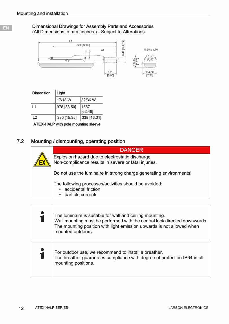
Mounting and installationENENENENENENENENENENENENENENENENENENENENENENENENEN
7.2 Mounting / dismounting, operating position
Dimension Light
17/18 W 32/36 W
L1 978 [38.50] 1587 [62.48]
L2 390 [15.35] 338 [13.31] ATEX-HALP with pole mounting sleeve
DANGERExplosion hazard due to electrostatic dischargeNon-complicance results in severe or fatal injuries.
Do not use the luminaire in strong charge generating environments!
The following processes/activities should be avoided:• accidental friction• particle currents
The luminaire is suitable for wall and ceiling mounting.Wall mounting must be performed with the central lock directed downwards. The mounting position with light emission upwards is not allowed when mounted outdoors.
For outdoor use, we recommend to install a breather. The breather guarantees compliance with degree of protection IP64 in all mounting positions.
Dimensional Drawings for Assembly Parts and Accessories (All Dimensions in mm [inches]) - Subject to Alterations
12 LARSON ELECTRONICSATEX-HALP SERIES

Mounting and installation ENENENENENENENENENENENENENENENENENENENENENENENENEN
Suspension at fixed mounting points
Suspension at moveable assembly parts
DANGERExplosion hazard due to inadmissible heating!Non-compliance results in severe or fatal injuries.
• Avoid external heat sources and/or direct sunlight (risk of change oftemperature class or change of maximum permissible surfacetemperature).
• Do not exceed the maximum ambient temperature due to external heatsources (premature failure of equipment).
max. screw-in depth 10 mm
Mounting bracket Top rail
Lateral mounting pockets for variable suspension points.
When mounting the luminaire using top rails, ensure that the mounting sur-face is flat. Otherwise, the enclosure might be mounted in a warped/twisted way. The result is leakage of the luminaire and difficulties in replacing the translucent cover.
L2
Version L2 [mm]17/18 W 40032/36 W 80040/58 W
L
L4
L
L4
L
L
Version L4 [mm] L [mm]17/18 W 320 8032/36 W 670 13040/58 W
LARSON ELECTRONICS 13ATEX-HALP SERIES

Mounting and installationENENENENENENENENENENENENENENENENENENENENENENENENEN
Pole mountingPole mounting using pipe clamps
Pole mounting using pole mounting sleeve
Version L4 [mm] L [mm]17/18 W 320 8032/36 W 670 13040/58 W
For pipe clamp mounting, use integrated mounting rail providing reliable and stable four-point fixing! In case of point suspension using pipe clamps, Larson Electronics does not guarantee the strength and tightness of the luminaire!
Only for luminaires length 700 mm and 1310 mm.
L4
L
L
14 LARSON ELECTRONICSATEX-HALP SERIES
Mounting and installation ENENENENENENENENENENENENENENENENENENENENENENENENEN
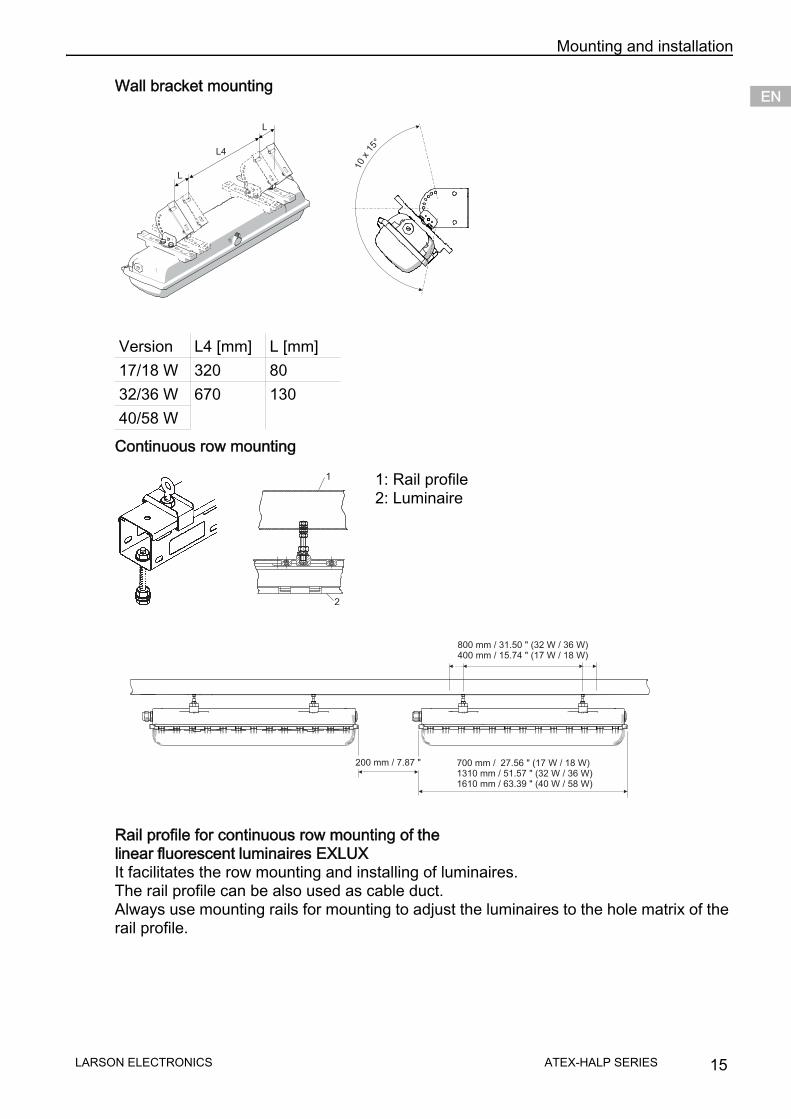
Wall bracket mounting
Continuous row mounting
Rail profile for continuous row mounting of the linear fluorescent luminaires EXLUXIt facilitates the row mounting and installing of luminaires.The rail profile can be also used as cable duct.Always use mounting rails for mounting to adjust the luminaires to the hole matrix of the rail profile.
Version L4 [mm] L [mm]17/18 W 320 8032/36 W 670 13040/58 W
1: Rail profile2: Luminaire
L
L4
L
10
x15
°
2
1
700 mm / 27.56 " (17 W / 18 W)1310 mm / 51.57 " (32 W / 36 W)1610 mm / 63.39 " (40 W / 58 W)
800 mm / 31.50 " (32 W / 36 W)400 mm / 15.74 " (17 W / 18 W)
200 mm / 7.87 "
LARSON ELECTRONICS 15ATEX-HALP SERIES
Mounting and installationENENENENENENENENENENENENENENENENENENENENENENENENEN
7.3 Installation
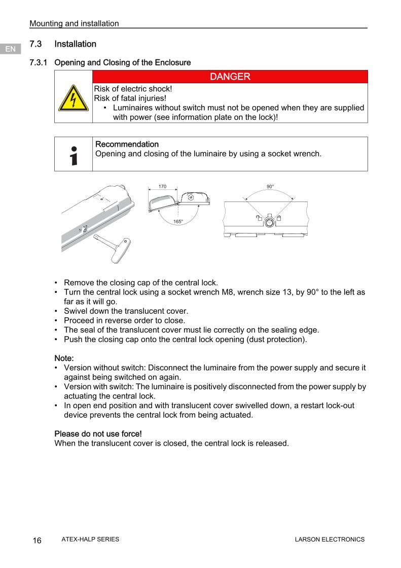
7.3.1 Opening and Closing of the Enclosure
• Remove the closing cap of the central lock.• Turn the central lock using a socket wrench M8, wrench size 13, by 90° to the left as
far as it will go.• Swivel down the translucent cover.• Proceed in reverse order to close.• The seal of the translucent cover must lie correctly on the sealing edge.• Push the closing cap onto the central lock opening (dust protection).
Note:• Version without switch: Disconnect the luminaire from the power supply and secure it
against being switched on again.• Version with switch: The luminaire is positively disconnected from the power supply by
actuating the central lock.• In open end position and with translucent cover swivelled down, a restart lock-out
device prevents the central lock from being actuated.
Please do not use force!When the translucent cover is closed, the central lock is released.
DANGERRisk of electric shock! Risk of fatal injuries!
• Luminaires without switch must not be opened when they are suppliedwith power (see information plate on the lock)!
RecommendationOpening and closing of the luminaire by using a socket wrench.
165°
170 90°
16 LARSON ELECTRONICSATEX-HALP SERIES
Mounting and installation ENENENENENENENENENENENENENENENENENENENENENENENENEN
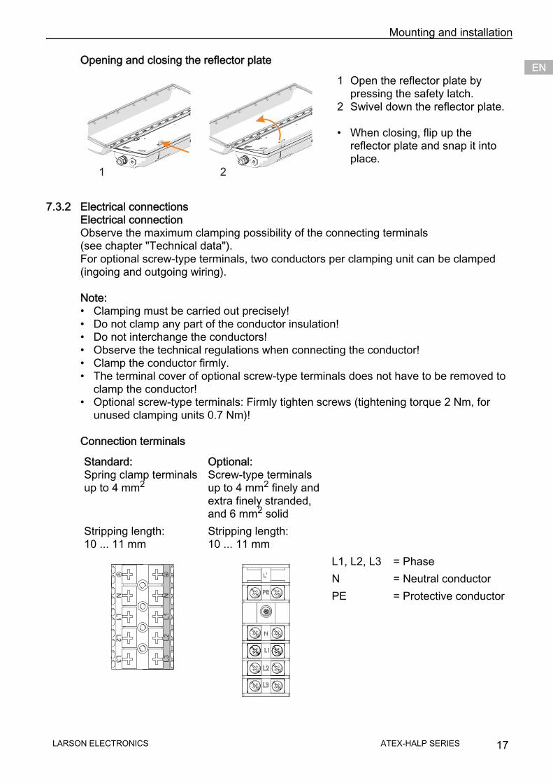
Opening and closing the reflector plate
7.3.2 Electrical connectionsElectrical connectionObserve the maximum clamping possibility of the connecting terminals (see chapter "Technical data"). For optional screw-type terminals, two conductors per clamping unit can be clamped (ingoing and outgoing wiring).
Note:• Clamping must be carried out precisely!• Do not clamp any part of the conductor insulation!• Do not interchange the conductors!• Observe the technical regulations when connecting the conductor!• Clamp the conductor firmly.• The terminal cover of optional screw-type terminals does not have to be removed to
clamp the conductor!• Optional screw-type terminals: Firmly tighten screws (tightening torque 2 Nm, for
unused clamping units 0.7 Nm)!
Connection terminals
1 Open the reflector plate by pressing the safety latch.
2 Swivel down the reflector plate.
• When closing, flip up thereflector plate and snap it intoplace.
Standard: Spring clamp terminals up to 4 mm2
Optional: Screw-type terminals up to 4 mm2 finely and extra finely stranded, and 6 mm2 solid
Stripping length:10 ... 11 mm
Stripping length:10 ... 11 mm
1 2N
L1
L2
L3
L3
L2
L1
N
L1, L2, L3 = PhaseN = Neutral conductorPE = Protective conductor
LARSON ELECTRONICS 17ATEX-HALP SERIES

Mounting and installationENENENENENENENENENENENENENENENENENENENENENENENENEN
Through wiring
7.3.3 Cable entriesThe standard luminaire is delivered with 3 lead-in holes, 2 cable glands and 2 stopping plug.Please observe the tightening torque for luminaires with installed cable glands and stopping plugs.
Luminaires with approved cable glands and stopping plugs; not supplied by Larson Electronics.
Please note:• the required dust resistance!• the required type of protection!• the required temperature resistance!• the IP degree of protection according to the rating plate!• the operating instructions of the cable glands and stopping plugs!• the required tightening torques!• the range of the permissible cable diameter!
NOTEThrough wiring with 2.5 mm 2 cross-section for max. 16 A.
Tightening torqueConnection thread Pressure screw
Cable gland 8161M20 x 1.5 2.3 Nm 1.5 NmM25 x 1.5 3.0 Nm 2.0 Nm
Stopping plugs 8290M20 x 1.5 1.0 NmM25 x 1.5 1.5 Nm
WARNINGCable glands and stopping plugs which are not approved.Explosion protection is impaired!
• Only use separately certified cable glands and stopping plugs.
18 LARSON ELECTRONICSATEX-HALP SERIES
CommissioningENENENENENENENENENENENENENENENENENENENENENENENENEN
8 Commissioning
Before commissioning, ensure that• the device has been installed according to regulations.• the power supply voltage and the rated operational voltage are identical.• the required cable diameter for cable glands has been used.• the cable entries and stopping plugs have been securely tightened.• the cables are correctly connected.• the connection has been performed correctly.• all screws and nuts are tightened according to regulations.• the connection chamber is clean.• the device is not damaged.• no foreign bodies are inside the device.• the device is sealed according to regulations.
9 Operation
9.1 Troubleshooting
If the error cannot be eliminated using the mentioned procedures:
For fast processing, have the following information ready: • Type and serial number• Purchase information• Error description• Intended use (in particular input / output wiring)
DANGERExplosion hazard due to incorrect installation!Non-compliance results in severe or fatal injuries.
• Check the device for proper installation and function beforecommissioning.
• Comply with the national regulations.
NOTECondensationdue to specific environmental and operating conditions condensation cannot be avoided completely.
• operate the luminaire continuously or periodically over extended periods of time!• avoid thermal bridges!
Cause MeasureThe lamp was incorrectly inserted. Insert the lamp correctly.The lamp is defective. Replace the lamp.The ballast is defective. Replace the ballast.The switch is defective. Replace the switch.The lamp reached its end of service life. Replace the lamp.
LARSON ELECTRONICS 19ATEX-HALP SERIES
Maintenance and repairENENENENENENENENENENENENENENENENENENENENENENENENEN
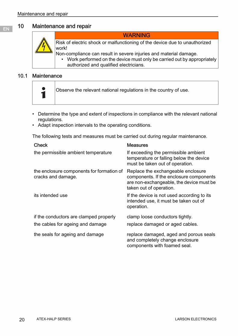
10 Maintenance and repair
10.1 Maintenance
• Determine the type and extent of inspections in compliance with the relevant nationalregulations.
• Adapt inspection intervals to the operating conditions.
The following tests and measures must be carried out during regular maintenance.
WARNINGRisk of electric shock or malfunctioning of the device due to unauthorized work!Non-compliance can result in severe injuries and material damage.
• Work performed on the device must only be carried out by appropriatelyauthorized and qualified electricians.
Observe the relevant national regulations in the country of use.
Check Measuresthe permissible ambient temperature If exceeding the permissible ambient
temperature or falling below the device must be taken out of operation.
the enclosure components for formation of cracks and damage.
Replace the exchangeable enclosure components. If the enclosure components are non-exchangeable, the device must be taken out of operation.
its intended use If the device is not used according to its intended use, it must be taken out of operation.
if the conductors are clamped properly clamp loose conductors tightly.the cables for ageing and damage replace damaged or aged cables.
the seals for ageing and damage replace damaged, aged and porous seals and completely change enclosure components with foamed seal.
20 LARSON ELECTRONICSATEX-HALP SERIES

Maintenance and repair ENENENENENENENENENENENENENENENENENENENENENENENENEN
10.1.1 Replacement of lamps
Note:• The lamp bases must be undamaged.• The holders have a springy length compensation of 2.5 mm each.• Observe the fit of the lamp; the lamp fit will be locked after turning the lamp.• Replace the lamps in due time.• Observe the service life specified by the manufacturer.• EOL- safety shutdown: The EB switches off the lamp at the end of the service life.
10.1.2 Replacing the luminaire cover
10.1.3 Cleaning
• Clean the device only with a damp cloth.• Use water or mild cleaning agents.• Do not use abrasive, scratching and aggressive detergents or solvents.
Only use fluorescent lamps with pins made of brass.
• Insert both lamp bases of the lamp into theholder slots as far as possible.
• Put the lamp into operating position byturning it to the right or to the left.
• Dismounting is carried out in reverseorder.
• Open the luminaire.• Swivel the translucent cover backwards by 180°.• Lift the translucent cover to detach it from the hinge.• Insert new translucent cover into the hinge.• All hinges must engage properly.• Close the luminaire.• Observe safety notes!
NOTEThe luminaire is marked with the warning "Clean with damp cloth only".
180°
LARSON ELECTRONICS 21ATEX-HALP SERIES
DisposalENENENENENENENENENENENENENENENENENENENENENENENENEN
10.2 Returning the deviceContact Larson Electronics customer service at the phone number listed below. Please have your order number ready.
11 Disposal• Observe national and local regulations and statutory regulation regarding disposal.• Separate materials when sending it for recycling.• Ensure environmentally friendly disposal of all components according to the statutory
regulations.
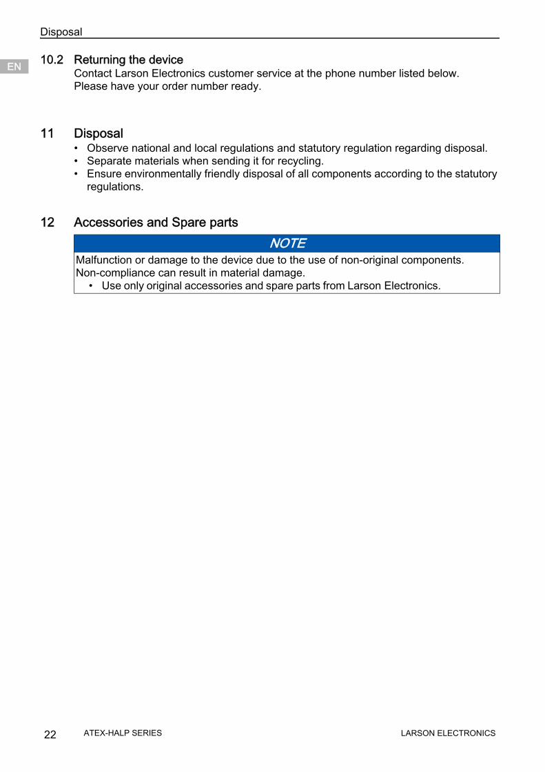
12 Accessories and Spare parts NOTE
Malfunction or damage to the device due to the use of non-original components.Non-compliance can result in material damage.
• Use only original accessories and spare parts from Larson Electronics.
22 LARSON ELECTRONICSATEX-HALP SERIES