LINEAR GRATE SHOWER BASE INSTALLATION GUIDE
44
LINEAR GRATE SHOWER BASE INSTALLATION GUIDE
Transcript of LINEAR GRATE SHOWER BASE INSTALLATION GUIDE
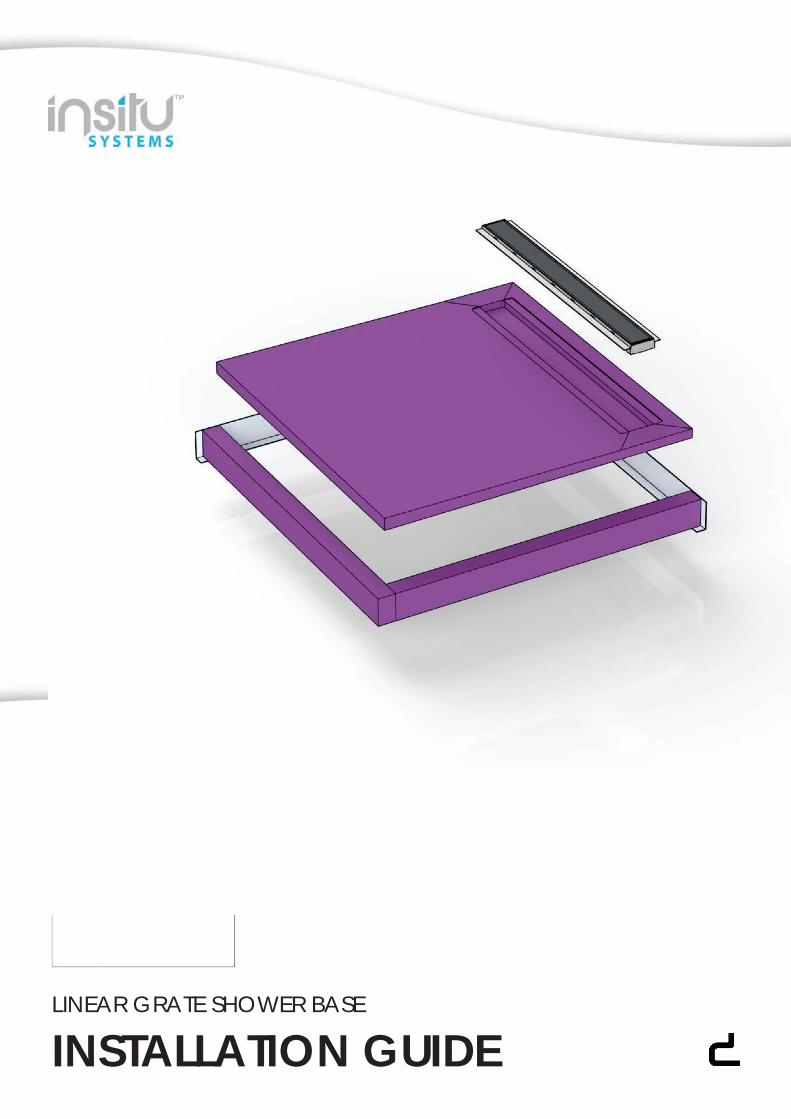
LINEAR GRATE SHOWER BASE
INSTALLATION GUIDE
LINEAR GRATE SHOWER BASE
IMPORTANT INFO
THIS GUIDE
This document is a guide only and does not cover all unforeseen onsite circumstances. The information within this guide is designed to assist with installation of the systems. A tradesman, builder or DIY’er must draw on trade skill/knowledge to overcome onsite challenges that are not covered within this document as not all variants of site preparation can be predicted or covered.
THE SYSTEM
ISB (Insitu Shower Base) and IPS (Insitu Panelling System) are a fully customizable precision made panelling systems designed to eliminate the use of sand and cement screeds. The weight reduction is of great benefit in relation to overcoming structural engineering challenges and compliment light weight construction. All ISB and IPS panels are constructed of a light weight water resistant formulation and are CNC machined to millimetre perfect dimensions including fall ratios that meet and often far exceed Australian Standard requirements. The panels are able to be manufactured in a range of profile thicknesses and are available in an advanced ‘click’ system to cover large areas. Demtech offer these technologically advance panelling systems in a variety of ‘centre/off-centre’ and linear grate style finishes. A factory protective coat of membrane is applied to each panel before dispatch. (This does not form any part of the required waterproofing system to be applied after panel installation is complete). The ISB and IPS dramatically reduce onsite down time as they are fully cured in an average 48 hours (temperature dependant). Both Demtech ISB and IPS can be installed and waterproofed in the same day and allowed to cure as a complete system (application dependant).
All ISB, IPS and WP systems are tried and tested and are BRANZ approved including all Insitu, Cureflex and Nero product ranges. Nero products are all WaterMarked and meet Australian standard requirements.
RECOMMENDATIONS
All ISB and IPS systems both internal and external require a full liquid membrane system applied over them once installed and cured. These waterproofing systems must meet the’ Australian Standards ‘AS3740 for internal and AS4654 for external. Waterproofing systems applied over the ISB and IPS systems should utilize water based acrylic products. The Demtech ISB and IPS system is not a waterproof system in its self but can be made water tight through correct and thorough installation processes. Products that are tried and tested and have attained a full Branz approval for waterproofing application over ISB and IPS systems can be found in our Cureflex and Trims ‘n’ Finishes range. It is the responsibility of the builder, tradesman or user to ensure that all substrates and structures constructed/installed prior to installation of the Demtech ISB and IPS systems are compliant with the Australian Standards requirement, building codes and are constructed/installed in accordance to all manufacturers’ recommendations. ISB and IPS are not ‘self-supporting’ (non-structural) and require standard flooring structures both internally and externally that comply with all building codes, Australian Standards and manufactures recommendations.
WARRANTY
The products supplied in the Demtech ISB and IPS systems as well as materials are covered under a factory product warranty. That is that the products themselves are supplied without manufacturing fault from factory. Workmanship including installation and modification of the Demtech ISB and IPS systems is not covered by Demtech as a manufacturer of the products. This warranty responsibility and obligation is held by the party completing the installation and or modification of the systems supplied. Demtech take no responsibility for workmanship or installation of these systems completed by third party persons.
For further information on our products, systems and services visit our website at www.demtech.com.au or contact your local distributor.
WHAT’S REQUIRED
01. Aluminium Collars02. InsituTM Shower Base03. AquafloTM Linear Water Grate04. NeroTM Sleeve & Grommet OR 04. NeroTM Sleeve Extension & Grommet05. Protective Matting06. PVC Flashing07. Hob Waterstops OR07. Aluminium Waterstops08. Barrier Tape09. CureflexTM HV124 Silane10. CureflexTM PG57 Primer11. CureflexTM TX88 Tile Adhesive12. Drill Guide13. Warning Sign14. 51mm & 83mm Hole Saws14. 5.5mm Drill Bit14. Arbour Drill Bit15. 75mm Wood Screws15. 75mm Hex Drive Screws15. 25mm Wood Screws15. Deburring Tool
01. Caulking Gun02. Cordless Drill03. Dustpan & Brush04. 600/900/1200mm Level05. Mixing Drill/Attachment06. Paint Roller (230mm max.)07. Paint Brush (100mm max.)08. PH2 Driver Drill Bit09. Pencil/Marker10. Small Handsaw11. Spatula12. Tinsnips13. Utility Knife14. 12mm Notched Trowel15. 5.5mm Hex Drive Drill Bit15. 10mm Punch Tool17. Hammer18. Chisel
01.Demtech Australia Pty. LtdPhone: 1300 300 090Web: www.demtech.com.au
Installation GuideRevised: July 2020
Version: 1.0.0

LINEAR GRATE SHOWER BASE
WHAT’S REQUIRED
01 02 03 04 05 06
07 08 09 10 11 12
13 14 15
01 02 03 04 05 06
07 08 09 10 11 12
13 14 15 17 1816
16
02.Demtech Australia Pty. LtdPhone: 1300 300 090Web: www.demtech.com.au
Installation GuideRevised: July 2020
Version: 1.0.0
LINEAR GRATE SHOWER BASE
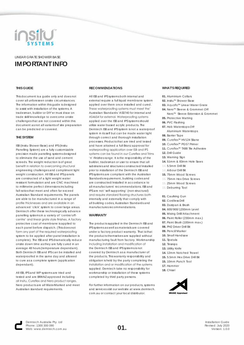
HOB WATERSTOPHOB WATERSTOP DESIGN VARIATION
01.Two walls, two hob waterstops.
02.Three walls, one hob waterstop.
03.In some cases, hob waterstops can be butted together to complete the shower base perimeter, as shown here.
In these cases, always apply silane between the adjoining faces of the hob waterstops.
03.Demtech Australia Pty. LtdPhone: 1300 300 090Web: www.demtech.com.au
Installation GuideRevised: July 2020
Version: 1.0.0
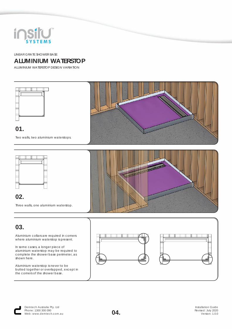
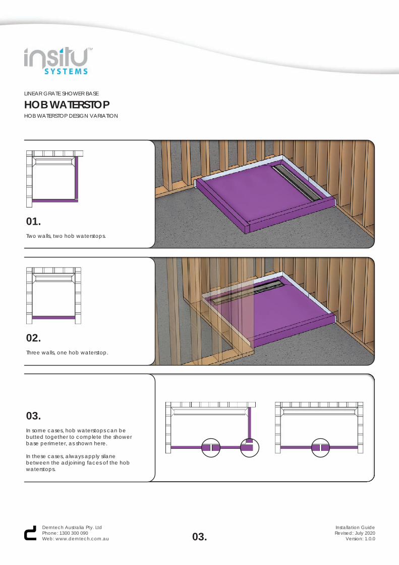
01.Two walls, two aluminium waterstops.
02.Three walls, one aluminium waterstop.
03.Aluminium collars are required in corners where aluminium waterstop is present.
In some cases, a longer piece of aluminium waterstop may be required to complete the shower base perimeter, as shown here.
Aluminium waterstop is never to be butted together or overlapped, except in the corners of the shower base.
LINEAR GRATE SHOWER BASE
ALUMINIUM WATERSTOPALUMINIUM WATERSTOP DESIGN VARIATION
04.Demtech Australia Pty. LtdPhone: 1300 300 090Web: www.demtech.com.au
Installation GuideRevised: July 2020
Version: 1.0.0
LINEAR GRATE SHOWER BASE
INSTALLATION STEPS
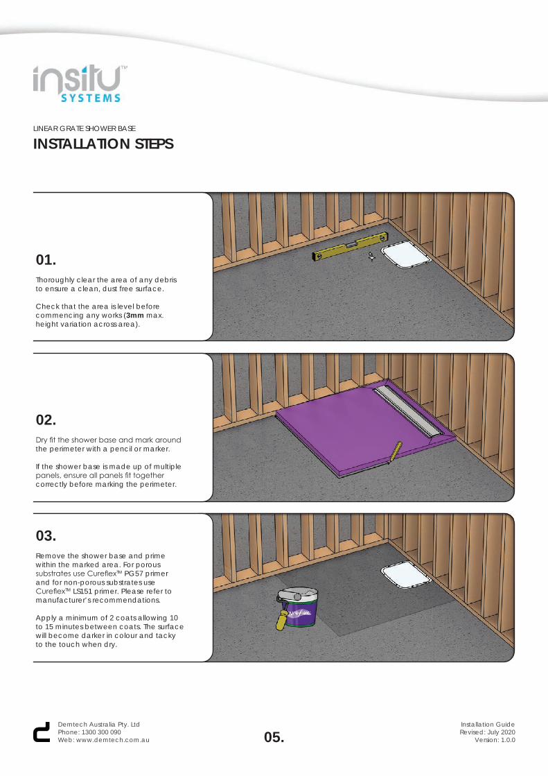
01.Thoroughly clear the area of any debris to ensure a clean, dust free surface.
Check that the area is level before commencing any works (3mm max. height variation across area).
02.Dry fit the shower base and mark around the perimeter with a pencil or marker.
If the shower base is made up of multiple panels, ensure all panels fit together correctly before marking the perimeter.
03.Remove the shower base and prime within the marked area. For porous substrates use CureflexTM PG57 primer and for non-porous substrates use CureflexTM LS151 primer. Please refer tomanufacturer’s recommendations.
Apply a minimum of 2 coats allowing 10 to 15 minutes between coats. The surface will become darker in colour and tacky to the touch when dry.
05.Demtech Australia Pty. LtdPhone: 1300 300 090Web: www.demtech.com.au
Installation GuideRevised: July 2020
Version: 1.0.0
LINEAR GRATE SHOWER BASE
INSTALLATION STEPS
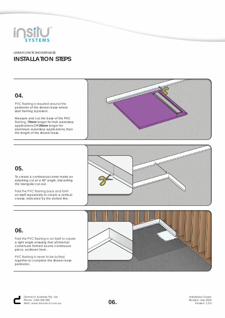
04.PVC flashing is required around the perimeter of the shower base where stud framing is present.
Measure and cut the base of the PVC flashing, 70mm longer for hob waterstop applications OR 20mm longer for aluminium waterstop applications, than the length of the shower base.
05.To create a continuous corner make an adjoining cut at a 45° angle, discarding the triangular cut-out.
Fold the PVC flashing back and forthon itself repeatedly to create a verticalcrease, indicated by the dotted line.
06.Fold the PVC flashing in on itself to create a right angle ensuring that all internal corners are formed as one continuous piece, as shown here.
PVC flashing is never to be butted together to complete the shower base perimeter.
06.Demtech Australia Pty. LtdPhone: 1300 300 090Web: www.demtech.com.au
Installation GuideRevised: July 2020
Version: 1.0.0
LINEAR GRATE SHOWER BASE
INSTALLATION STEPS
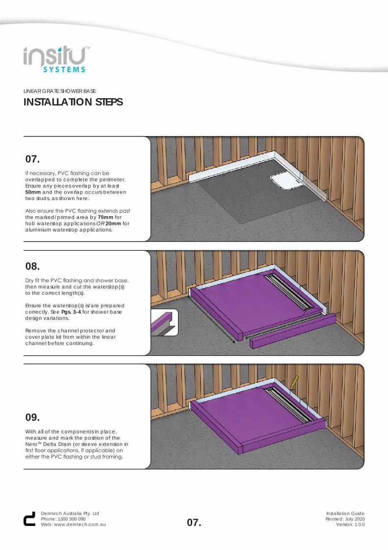
07.If necessary, PVC flashing can be overlapped to complete the perimeter. Ensure any pieces overlap by at least 50mm and the overlap occurs between two studs, as shown here.
Also ensure the PVC flashing extends past the marked/primed area by 70mm for hob waterstop applications OR 20mm for aluminium waterstop applications.
08.Dry fit the PVC flashing and shower base, then measure and cut the waterstop(s) to the correct length(s).
Ensure the waterstop(s) is/are prepared correctly. See Pgs. 3-4 for shower base design variations.
Remove the channel protector and cover plate kit from within the linear channel before continuing.
09.With all of the components in place, measure and mark the position of the NeroTM Delta Drain (or sleeve extension in first floor applications, if applicable) on either the PVC flashing or stud framing.
07.Demtech Australia Pty. LtdPhone: 1300 300 090Web: www.demtech.com.au
Installation GuideRevised: July 2020
Version: 1.0.0
LINEAR GRATE SHOWER BASE
INSTALLATION STEPS
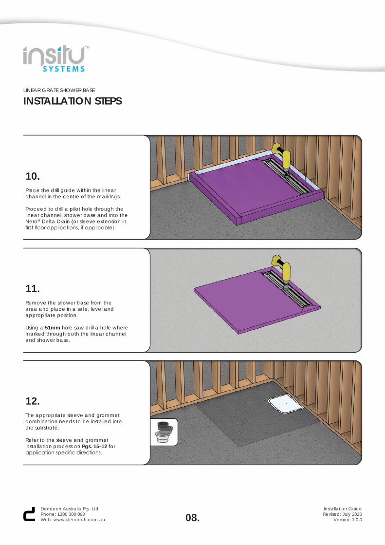
10.Place the drill guide within the linear channel in the centre of the markings.
Proceed to drill a pilot hole through the linear channel, shower base and into the NeroM Delta Drain (or sleeve extension in first floor applications, if applicable).
11.Remove the shower base from the area and place in a safe, level and appropriate position.
Using a 51mm hole saw drill a hole where marked through both the linear channel and shower base.
12.The appropriate sleeve and grommetcombination needs to be installed intothe substrate.
Refer to the sleeve and grommet installation process on Pgs. 15-12 for application specific directions.
08.Demtech Australia Pty. LtdPhone: 1300 300 090Web: www.demtech.com.au
Installation GuideRevised: July 2020
Version: 1.0.0
LINEAR GRATE SHOWER BASE
INSTALLATION STEPS
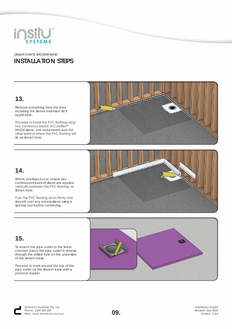
13.Remove everything from the area including the sleeve extension lid if applicable.
Proceed to install the PVC flashing using two continuous beads of CureflexTM HV124 silane, one underneath and the other behind where the PVC flashing will sit, as shown here.
14.Where overlaps occur, ensure twocontinuous beads of silane are appliedvertically between the PVC flashing, asshown here.
Push the PVC flashing down firmly andsmooth over any excess silane using aspatula tool before continuing.
15.To attach the pipe outlet to the linear channel, place the pipe outlet in reverse through the drilled hole on the underside of the shower base.
Proceed to mark around the top of the pipe outlet on the shower base with a pencil or marker.
09.Demtech Australia Pty. LtdPhone: 1300 300 090Web: www.demtech.com.au
Installation GuideRevised: July 2020
Version: 1.0.0
LINEAR GRATE SHOWER BASE
INSTALLATION STEPS
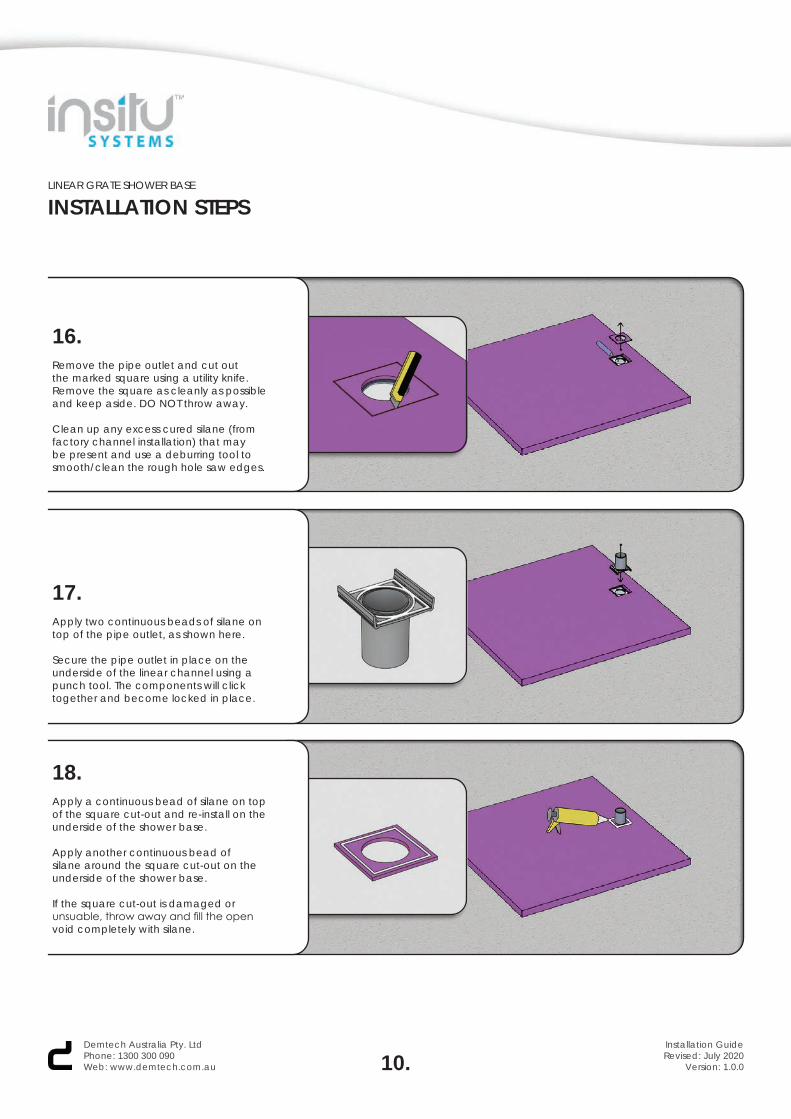
16.Remove the pipe outlet and cut out the marked square using a utility knife. Remove the square as cleanly as possible and keep aside. DO NOT throw away.
Clean up any excess cured silane (from factory channel installation) that may be present and use a deburring tool to smooth/clean the rough hole saw edges.
17.Apply two continuous beads of silane on top of the pipe outlet, as shown here.
Secure the pipe outlet in place on the underside of the linear channel using a punch tool. The components will click together and become locked in place.
18.Apply a continuous bead of silane on top of the square cut-out and re-install on the underside of the shower base.
Apply another continuous bead of silane around the square cut-out on the underside of the shower base.
If the square cut-out is damaged or unsuable, throw away and fill the open void completely with silane.
10.Demtech Australia Pty. LtdPhone: 1300 300 090Web: www.demtech.com.au
Installation GuideRevised: July 2020
Version: 1.0.0
LINEAR GRATE SHOWER BASE
INSTALLATION STEPS
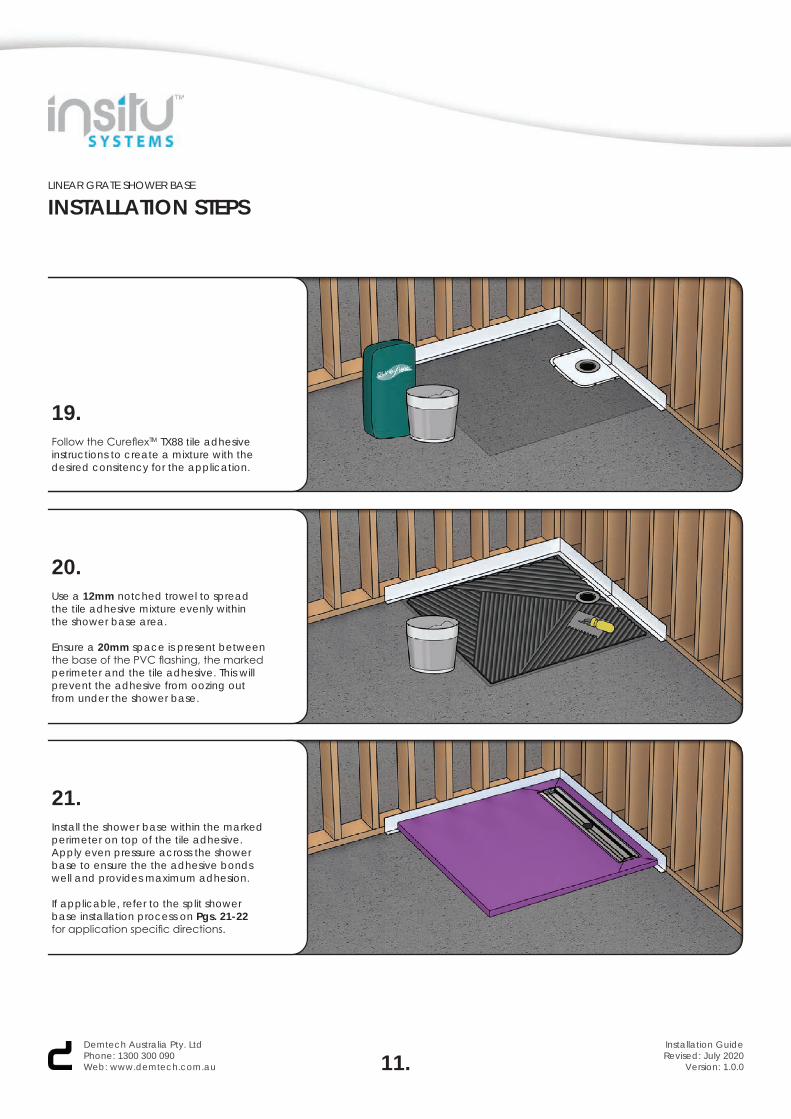
19.Follow the CureflexTM TX88 tile adhesiveinstructions to create a mixture with thedesired consitency for the application.
20.Use a 12mm notched trowel to spread the tile adhesive mixture evenly within the shower base area.
Ensure a 20mm space is present between the base of the PVC flashing, the marked perimeter and the tile adhesive. This will prevent the adhesive from oozing out from under the shower base.
21.Install the shower base within the marked perimeter on top of the tile adhesive. Apply even pressure across the shower base to ensure the the adhesive bonds well and provides maximum adhesion.
If applicable, refer to the split shower base installation process on Pgs. 21-22 for application specific directions.
11.Demtech Australia Pty. LtdPhone: 1300 300 090Web: www.demtech.com.au
Installation GuideRevised: July 2020
Version: 1.0.0

LINEAR GRATE SHOWER BASE
INSTALLATION STEPS
22.Check the level of the shower base inmultiple areas and make any necessaryadjustments before continuing.
Ensure the fall ratio is not compromised and meets the required standard.
23.Install the waterstop(s) in the same way as the PVC flashing using two continuous beads of silane, one underneath and the other behind where the waterstop(s) will sit, as shown here.
For hob waterstop applications, skip to Step 25. For aluminium waterstop applications follow Step 24.
24.In aluminium waterstop applications, aluminium collars are required in all discontinuous corners. Apply two continuous beads of silane on both back sides of the collar, as shown here.
Push the collars down between the shower base and PVC flashing/waterstop until they sit level and flush.
12.Demtech Australia Pty. LtdPhone: 1300 300 090Web: www.demtech.com.au
Installation GuideRevised: July 2020
Version: 1.0.0
LINEAR GRATE SHOWER BASE
INSTALLATION STEPS
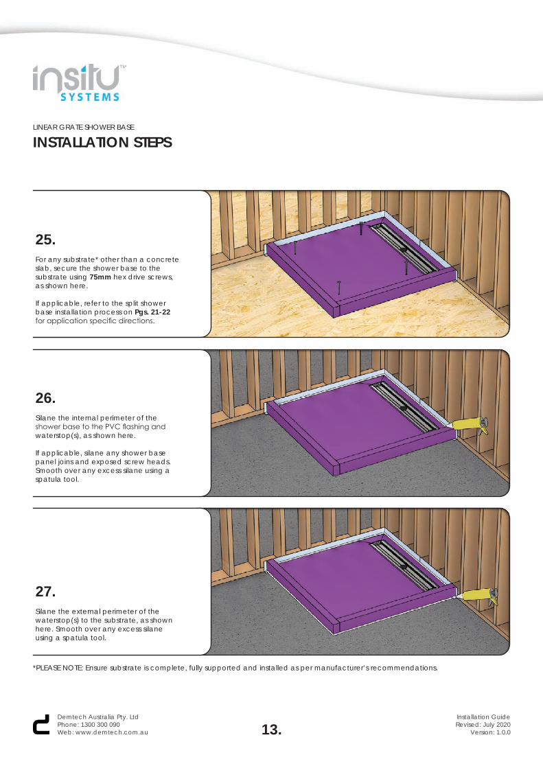
25.For any substrate* other than a concrete slab, secure the shower base to the substrate using 75mm hex drive screws, as shown here.
If applicable, refer to the split shower base installation process on Pgs. 21-22 for application specific directions.
26.Silane the internal perimeter of the shower base to the PVC flashing and waterstop(s), as shown here.
If applicable, silane any shower base panel joins and exposed screw heads. Smooth over any excess silane using a spatula tool.
27.Silane the external perimeter of the waterstop(s) to the substrate, as shown here. Smooth over any excess silane using a spatula tool.
13.Demtech Australia Pty. LtdPhone: 1300 300 090Web: www.demtech.com.au
Installation GuideRevised: July 2020
Version: 1.0.0
*PLEASE NOTE: Ensure substrate is complete, fully supported and installed as per manufacturer’s recommendations.
LINEAR GRATE SHOWER BASE
INSTALLATION STEPS
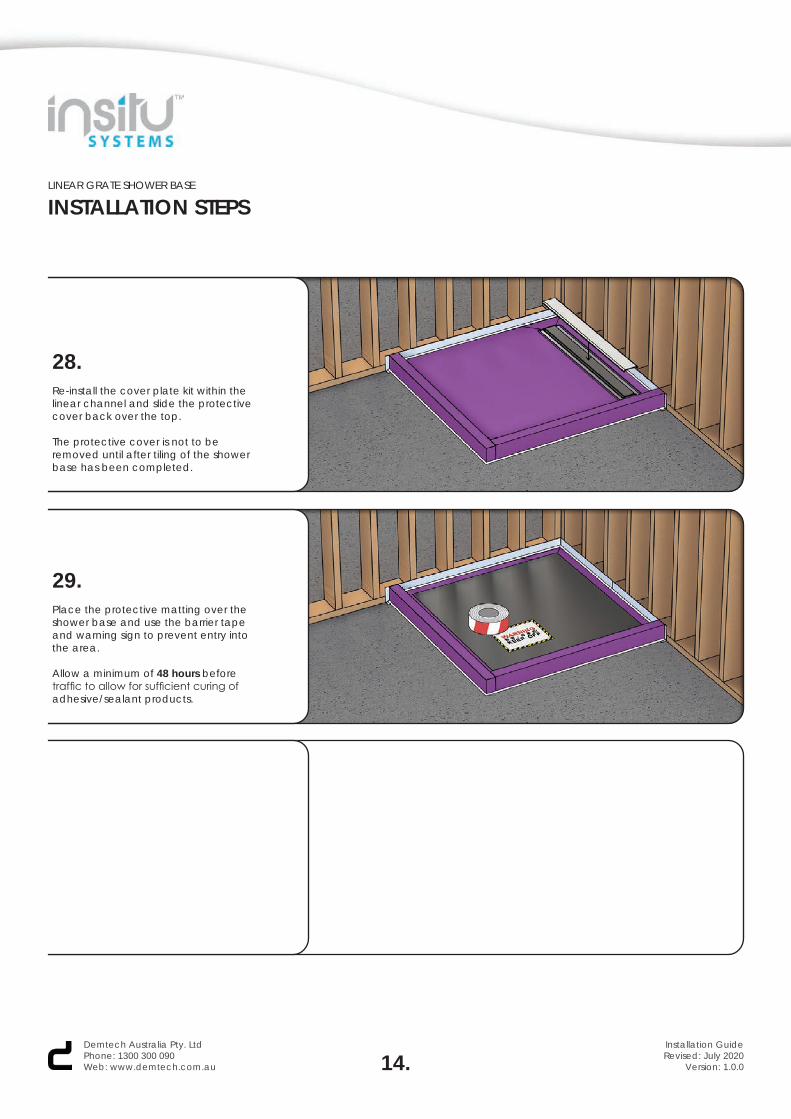
28.Re-install the cover plate kit within the linear channel and slide the protective cover back over the top.
The protective cover is not to be removed until after tiling of the shower base has been completed.
29.Place the protective matting over the shower base and use the barrier tape and warning sign to prevent entry into the area.
Allow a minimum of 48 hours before traffic to allow for sufficient curing of adhesive/sealant products.
14.Demtech Australia Pty. LtdPhone: 1300 300 090Web: www.demtech.com.au
Installation GuideRevised: July 2020
Version: 1.0.0
LINEAR GRATE SHOWER BASE
SLEEVE & GROMMETGROUND FLOOR DESIGN VARIATION
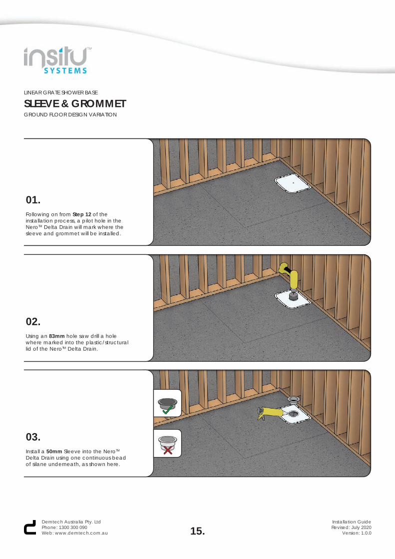
01.Following on from Step 12 of the installation process, a pilot hole in the NeroTM Delta Drain will mark where the sleeve and grommet will be installed.
02.Using an 83mm hole saw drill a hole where marked into the plastic/structural lid of the NeroTM Delta Drain.
03.Install a 50mm Sleeve into the NeroTM Delta Drain using one continuous bead of silane underneath, as shown here.
15.Demtech Australia Pty. LtdPhone: 1300 300 090Web: www.demtech.com.au
Installation GuideRevised: July 2020
Version: 1.0.0
LINEAR GRATE SHOWER BASE
SLEEVE & GROMMETGROUND FLOOR DESIGN VARIATION
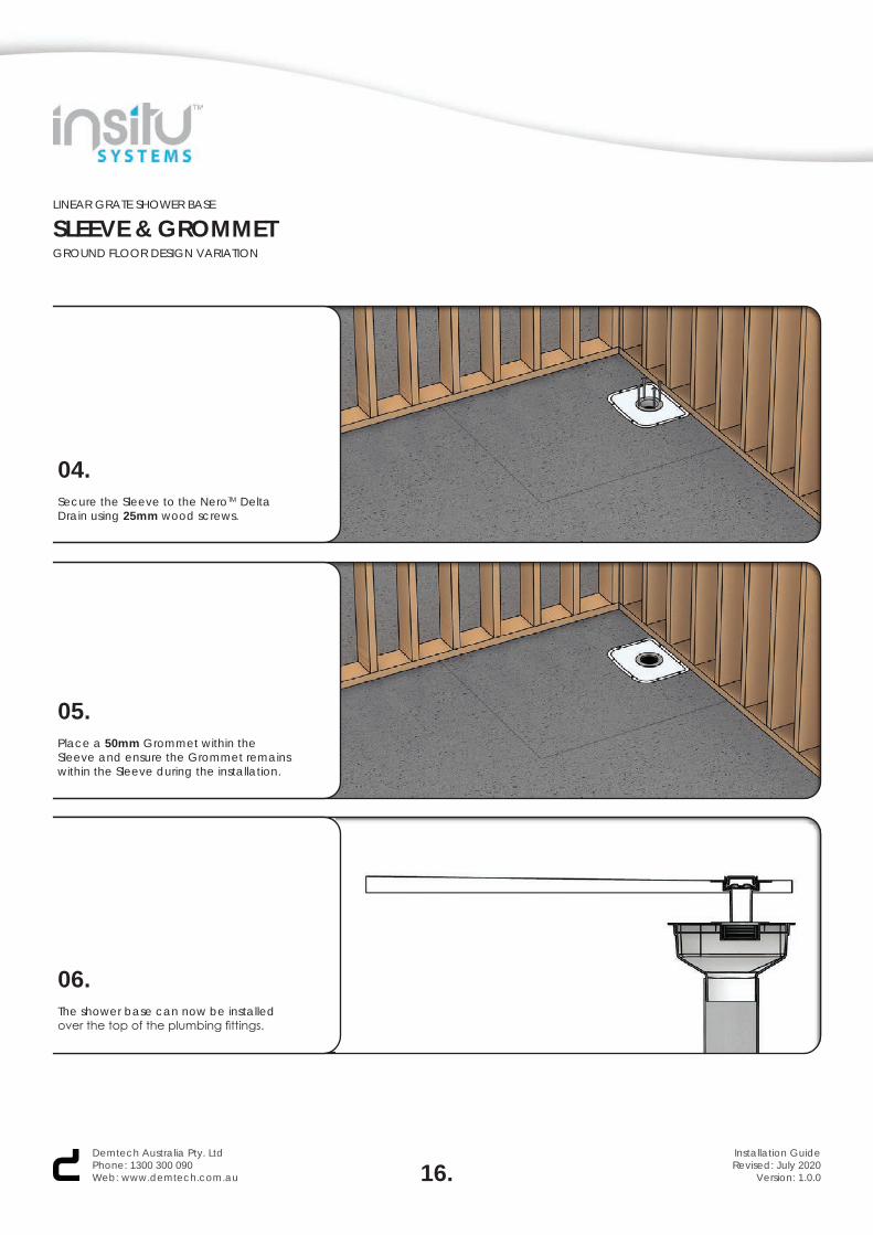
04.Secure the Sleeve to the NeroTM Delta Drain using 25mm wood screws.
05.Place a 50mm Grommet within the Sleeve and ensure the Grommet remains within the Sleeve during the installation.
16.Demtech Australia Pty. LtdPhone: 1300 300 090Web: www.demtech.com.au
Installation GuideRevised: July 2020
Version: 1.0.0
06.The shower base can now be installed over the top of the plumbing fittings.

LINEAR GRATE SHOWER BASE
SLEEVE & GROMMETFIRST FLOOR DESIGN VARIATION
01.Following on from Step 12 of the installation process, a pilot hole in the substrate* will mark where the sleeve extension and grommet will be installed.
02.Using an 83mm hole saw drill a hole where marked into the substrate.
03.Install a 50mm Sleeve Extension into the substrate using one continuous bead of silane underneath, as shown here.
17.Demtech Australia Pty. LtdPhone: 1300 300 090Web: www.demtech.com.au
Installation GuideRevised: July 2020
Version: 1.0.0
*PLEASE NOTE: Ensure substrate is complete, fully supported and installed as per manufacturer’s recommendations.
LINEAR GRATE SHOWER BASE
SLEEVE & GROMMETFIRST FLOOR DESIGN VARIATION
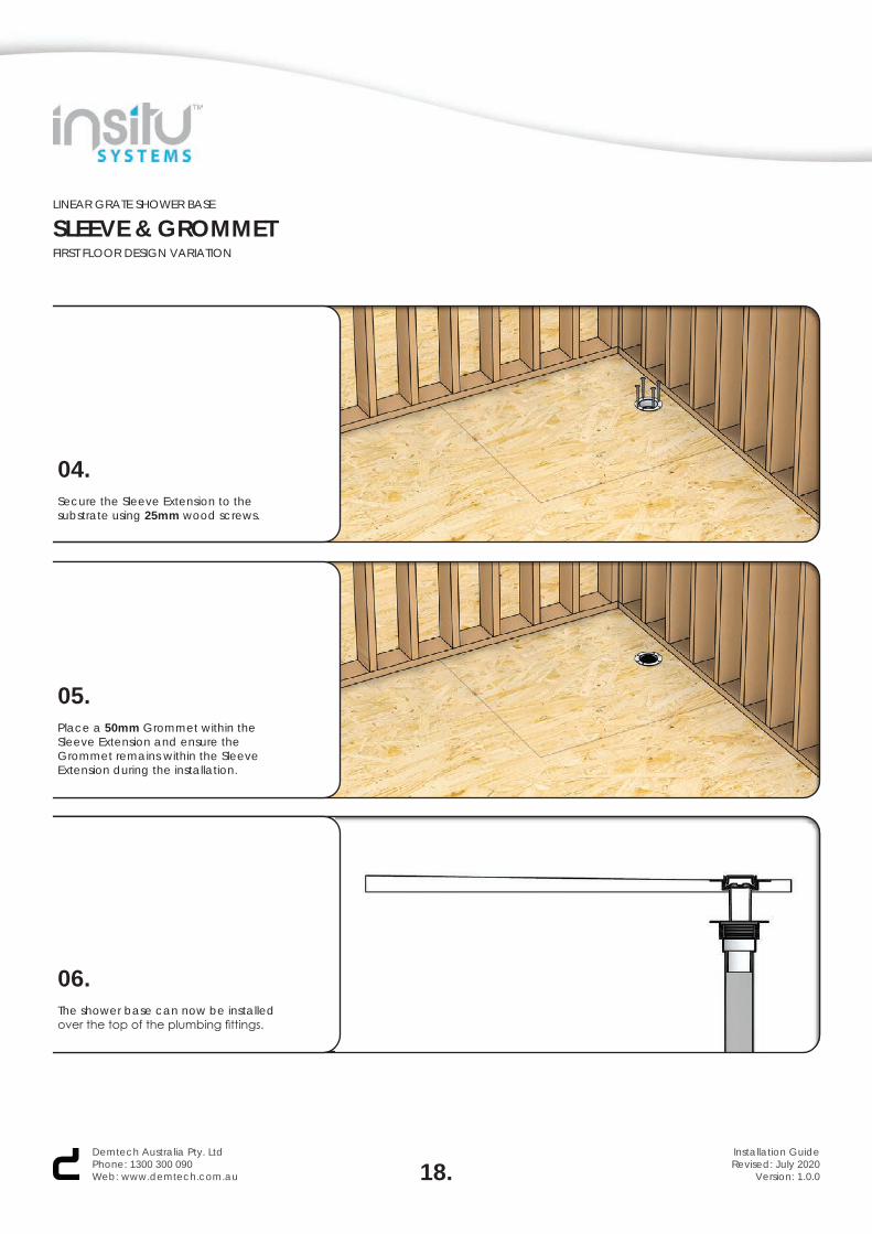
04.Secure the Sleeve Extension to the substrate using 25mm wood screws.
05.Place a 50mm Grommet within the Sleeve Extension and ensure the Grommet remains within the Sleeve Extension during the installation.
18.Demtech Australia Pty. LtdPhone: 1300 300 090Web: www.demtech.com.au
Installation GuideRevised: July 2020
Version: 1.0.0
06.The shower base can now be installed over the top of the plumbing fittings.
LINEAR GRATE SHOWER BASE
SLEEVE & GROMMETFIRST FLOOR DESIGN VARIATION
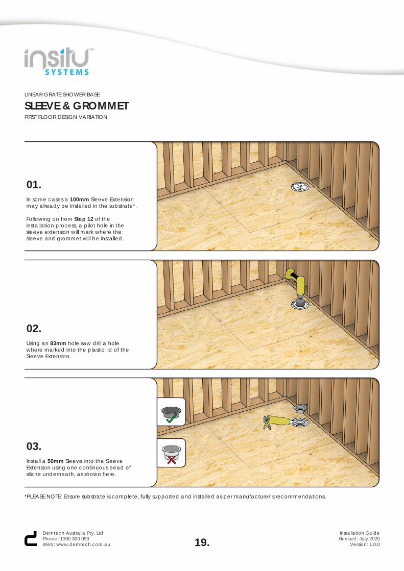
01.In some cases a 100mm Sleeve Extension may already be installed in the substrate*.
Following on from Step 12 of the installation process, a pilot hole in the sleeve extension will mark where the sleeve and grommet will be installed.
02.Using an 83mm hole saw drill a hole where marked into the plastic lid of the Sleeve Extension.
03.Install a 50mm Sleeve into the Sleeve Extension using one continuous bead of silane underneath, as shown here.
19.Demtech Australia Pty. LtdPhone: 1300 300 090Web: www.demtech.com.au
Installation GuideRevised: July 2020
Version: 1.0.0
*PLEASE NOTE: Ensure substrate is complete, fully supported and installed as per manufacturer’s recommendations.
LINEAR GRATE SHOWER BASE
SLEEVE & GROMMETFIRST FLOOR DESIGN VARIATION
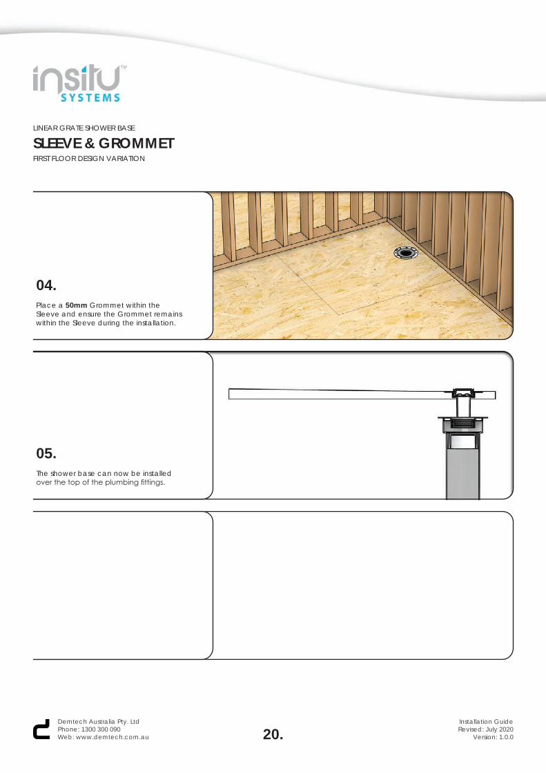
04.Place a 50mm Grommet within the Sleeve and ensure the Grommet remains within the Sleeve during the installation.
20.Demtech Australia Pty. LtdPhone: 1300 300 090Web: www.demtech.com.au
Installation GuideRevised: July 2020
Version: 1.0.0
05.The shower base can now be installed over the top of the plumbing fittings.
LINEAR GRATE SHOWER BASE
TONGUE & GROOVESPLIT SHOWER BASE DESIGN VARIATION
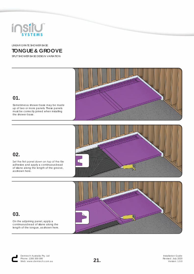
01.Sometimes a shower base may be made up of two or more panels. These panels must be correctly joined when installing the shower base.
02.Set the first panel down on top of the tile adhesive and apply a continuous bead of silane along the length of the groove, as shown here.
03.On the adjoining panel, apply a continuous bead of silane along the length of the tongue, as shown here.
21.Demtech Australia Pty. LtdPhone: 1300 300 090Web: www.demtech.com.au
Installation GuideRevised: July 2020
Version: 1.0.0
LINEAR GRATE SHOWER BASE
TONGUE & GROOVESPLIT SHOWER BASE DESIGN VARIATION
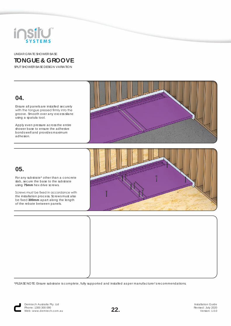
04.Ensure all panels are installed securely with the tongue pressed firmly into the groove. Smooth over any excess silane using a spatula tool.
Apply even pressure across the entire shower base to ensure the adhesive bonds well and provides maximum adhesion.
05.For any substrate* other than a concrete slab, secure the base to the substrate using 75mm hex drive screws.
Screws must be fixed in accordance with the installation process. Screws must also be fixed 300mm apart along the length of the rebate between panels.
22.Demtech Australia Pty. LtdPhone: 1300 300 090Web: www.demtech.com.au
Installation GuideRevised: July 2020
Version: 1.0.0
*PLEASE NOTE: Ensure substrate is complete, fully supported and installed as per manufacturer’s recommendations.
LINEAR GRATE SHOWER BASE
INSTALLATION GUIDE
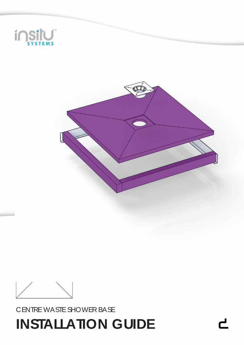
CENTRE WASTE SHOWER BASE
INSTALLATION GUIDE
CENTRE WASTE SHOWER BASE
IMPORTANT INFO
01.
WHAT’S REQUIRED
01. Aluminium Collars02. InsituTM Shower Base03. NeroTM Leak Control Flange (LCF)04. NeroTM Sleeve & Grommet OR 04. NeroTM Sleeve Extension & Grommet05. Protective Matting06. PVC Flashing07. Hob Waterstops OR07. Aluminium Waterstops08. Barrier Tape09. CureflexTM HV124 Silane10. CureflexTM PG57 Primer11. CureflexTM TX88 Tile Adhesive12. Warning Sign13. 133mm Hole Saw13. 5.5mm Drill Bit13. Arbour Drill Bit14. 25mm Wood Screws14. 75mm Wood Screws14. 75mm Hex Drive Screws
01. Caulking Gun02. Cordless Drill03. Dustpan & Brush04. 600/900/1200mm Level05. Mixing Drill/Attachment06. Paint Roller (230mm max.)07. Paint Brush (100mm max.)08. PH2 Driver Drill Bit09. Pencil/Marker10. Small Handsaw11. Spatula12. Tinsnips13. Utility Knife14. 12mm Notched Trowel15. 5.5mm Hex Drive Drill Bit16. Hammer17. Chisel
THIS GUIDE
This document is a guide only and does not cover all unforeseen onsite circumstances. The information within this guide is designed to assist with installation of the systems. A tradesman, builder or DIY’er must draw on trade skill/knowledge to overcome onsite challenges that are not covered within this document as not all variants of site preparation can be predicted or covered.
THE SYSTEM
ISB (Insitu Shower Base) and IPS (Insitu Panelling System) are a fully customizable precision made panelling systems designed to eliminate the use of sand and cement screeds. The weight reduction is of great benefit in relation to overcoming structural engineering challenges and compliment light weight construction. All ISB and IPS panels are constructed of a light weight water resistant formulation and are CNC machined to millimetre perfect dimensions including fall ratios that meet and often far exceed Australian Standard requirements. The panels are able to be manufactured in a range of profile thicknesses and are available in an advanced ‘click’ system to cover large areas. Demtech offer these technologically advance panelling systems in a variety of ‘centre/off-centre’ and linear grate style finishes. A factory protective coat of membrane is applied to each panel before dispatch. (This does not form any part of the required waterproofing system to be applied after panel installation is complete). The ISB and IPS dramatically reduce onsite down time as they are fully cured in an average 48 hours (temperature dependant). Both Demtech ISB and IPS can be installed and waterproofed in the same day and allowed to cure as a complete system (application dependant).
All ISB, IPS and WP systems are tried and tested and are BRANZ approved including all Insitu, Cureflex and Nero product ranges. Nero products are all WaterMarked and meet Australian standard requirements.
RECOMMENDATIONS
All ISB and IPS systems both internal and external require a full liquid membrane system applied over them once installed and cured. These waterproofing systems must meet the’ Australian Standards ‘AS3740 for internal and AS4654 for external. Waterproofing systems applied over the ISB and IPS systems should utilize water based acrylic products. The Demtech ISB and IPS system is not a waterproof system in its self but can be made water tight through correct and thorough installation processes. Products that are tried and tested and have attained a full Branz approval for waterproofing application over ISB and IPS systems can be found in our Cureflex and Trims ‘n’ Finishes range. It is the responsibility of the builder, tradesman or user to ensure that all substrates and structures constructed/installed prior to installation of the Demtech ISB and IPS systems are compliant with the Australian Standards requirement, building codes and are constructed/installed in accordance to all manufacturers’ recommendations. ISB and IPS are not ‘self-supporting’ (non-structural) and require standard flooring structures both internally and externally that comply with all building codes, Australian Standards and manufactures recommendations.
WARRANTY
The products supplied in the Demtech ISB and IPS systems as well as materials are covered under a factory product warranty. That is that the products themselves are supplied without manufacturing fault from factory. Workmanship including installation and modification of the Demtech ISB and IPS systems is not covered by Demtech as a manufacturer of the products. This warranty responsibility and obligation is held by the party completing the installation and or modification of the systems supplied. Demtech take no responsibility for workmanship or installation of these systems completed by third party persons.
For further information on our products, systems and services visit our website at www.demtech.com.au or contact your local distributor.
Demtech Australia Pty. LtdPhone: 1300 300 090Web: www.demtech.com.au
Installation GuideRevised: July 2020
Version: 1.0.0
CENTRE WASTE SHOWER BASE
WHAT’S REQUIRED
01 02 03 04 05 06
07 08 09 10 11 12
13 14
01 02 03 04 05 06
07 08 09 10 11 12
13 14 15 16 17
02.Demtech Australia Pty. LtdPhone: 1300 300 090Web: www.demtech.com.au
Installation GuideRevised: July 2020
Version: 1.0.0
CENTRE WASTE SHOWER BASE
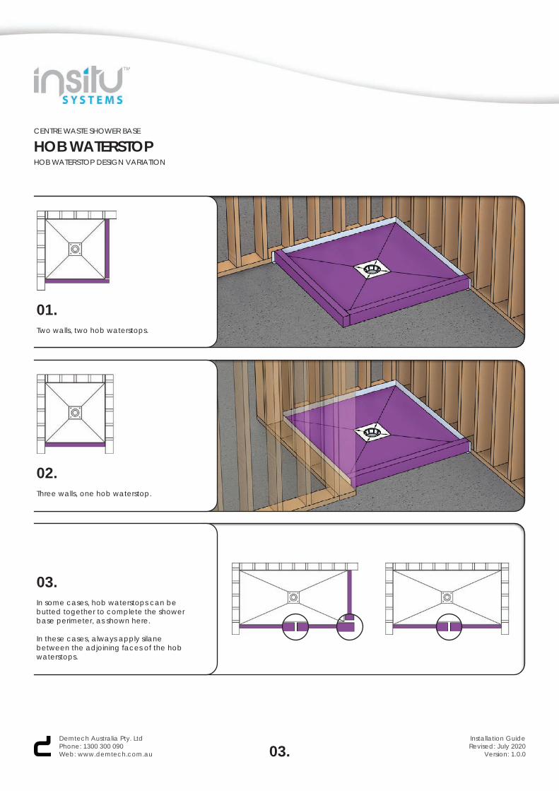
HOB WATERSTOPHOB WATERSTOP DESIGN VARIATION
01.Two walls, two hob waterstops.
02.Three walls, one hob waterstop.
03.In some cases, hob waterstops can be butted together to complete the shower base perimeter, as shown here.
In these cases, always apply silane between the adjoining faces of the hob waterstops.
03.Demtech Australia Pty. LtdPhone: 1300 300 090Web: www.demtech.com.au
Installation GuideRevised: July 2020
Version: 1.0.0
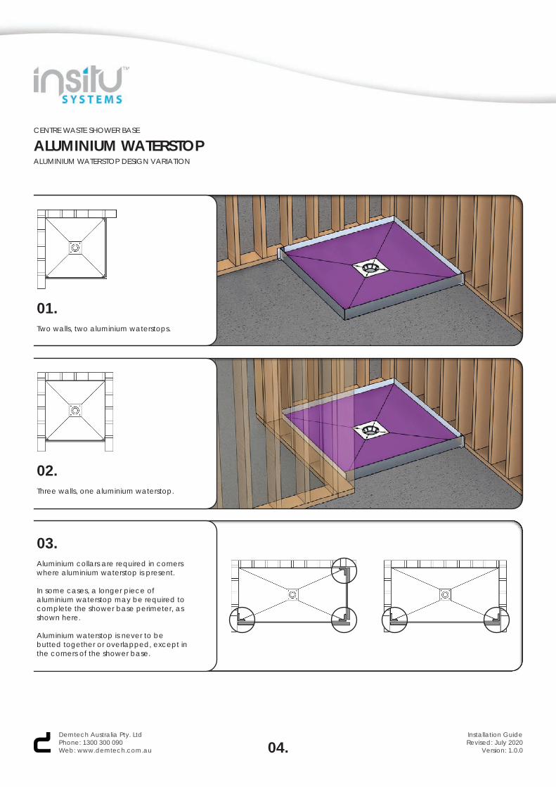
01.Two walls, two aluminium waterstops.
02.Three walls, one aluminium waterstop.
03.Aluminium collars are required in corners where aluminium waterstop is present.
In some cases, a longer piece of aluminium waterstop may be required to complete the shower base perimeter, as shown here.
Aluminium waterstop is never to be butted together or overlapped, except in the corners of the shower base.
CENTRE WASTE SHOWER BASE
ALUMINIUM WATERSTOPALUMINIUM WATERSTOP DESIGN VARIATION
04.Demtech Australia Pty. LtdPhone: 1300 300 090Web: www.demtech.com.au
Installation GuideRevised: July 2020
Version: 1.0.0
CENTRE WASTE SHOWER BASE
INSTALLATION STEPS
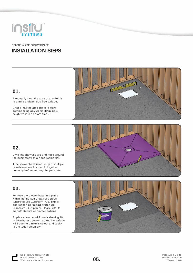
01.Thoroughly clear the area of any debris to ensure a clean, dust free surface.
Check that the area is level before commencing any works (3mm max. height variation across area).
02.Dry fit the shower base and mark around the perimeter with a pencil or marker.
If the shower base is made up of multiple panels, ensure all panels fit together correctly before marking the perimeter.
03.Remove the shower base and prime within the marked area. For porous substrates use CureflexTM PG57 primer and for non-porous substrates use CureflexTM LS151 primer. Please refer tomanufacturer’s recommendations.
Apply a minimum of 2 coats allowing 10 to 15 minutes between coats. The surface will become darker in colour and tacky to the touch when dry.
05.Demtech Australia Pty. LtdPhone: 1300 300 090Web: www.demtech.com.au
Installation GuideRevised: July 2020
Version: 1.0.0
CENTRE WASTE SHOWER BASE
INSTALLATION STEPS
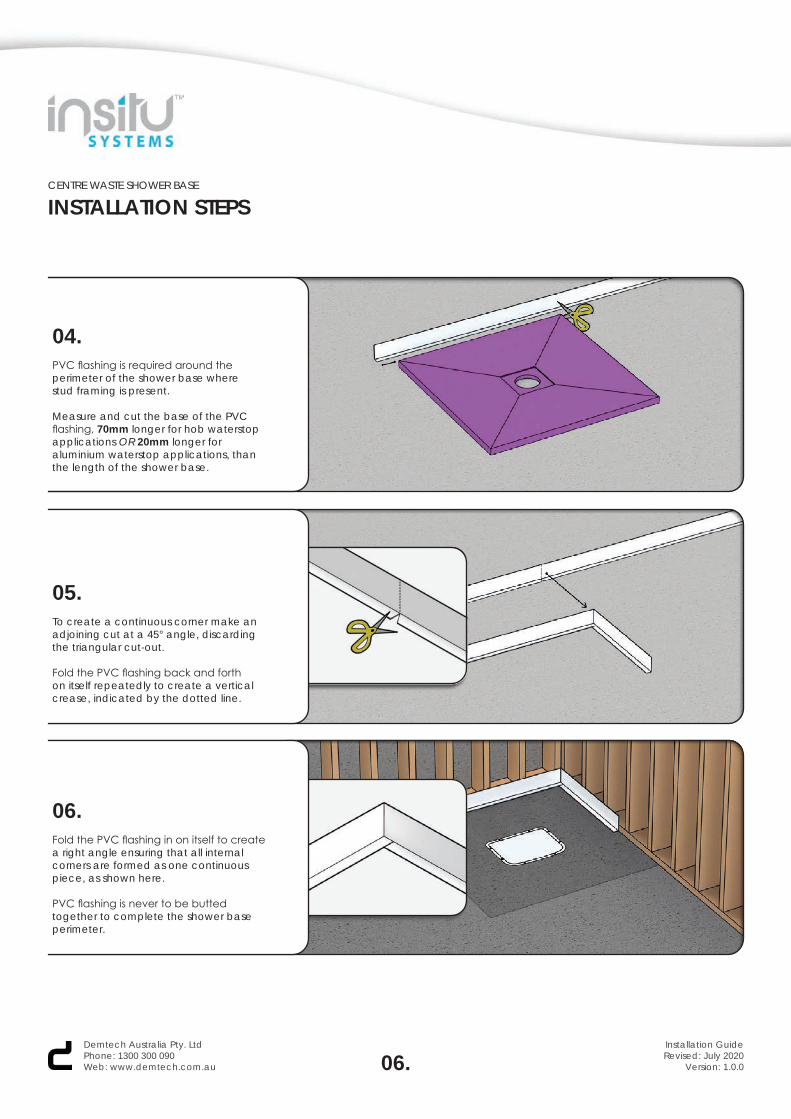
04.PVC flashing is required around the perimeter of the shower base where stud framing is present.
Measure and cut the base of the PVC flashing, 70mm longer for hob waterstop applications OR 20mm longer for aluminium waterstop applications, than the length of the shower base.
05.To create a continuous corner make an adjoining cut at a 45° angle, discarding the triangular cut-out.
Fold the PVC flashing back and forthon itself repeatedly to create a verticalcrease, indicated by the dotted line.
06.Fold the PVC flashing in on itself to create a right angle ensuring that all internal corners are formed as one continuous piece, as shown here.
PVC flashing is never to be butted together to complete the shower base perimeter.
06.Demtech Australia Pty. LtdPhone: 1300 300 090Web: www.demtech.com.au
Installation GuideRevised: July 2020
Version: 1.0.0
CENTRE WASTE SHOWER BASE
INSTALLATION STEPS
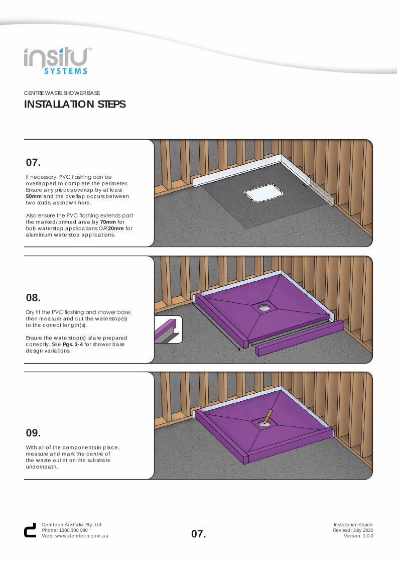
07.If necessary, PVC flashing can be overlapped to complete the perimeter. Ensure any pieces overlap by at least 50mm and the overlap occurs between two studs, as shown here.
Also ensure the PVC flashing extends past the marked/primed area by 70mm for hob waterstop applications OR 20mm for aluminium waterstop applications.
08.Dry fit the PVC flashing and shower base, then measure and cut the waterstop(s) to the correct length(s).
Ensure the waterstop(s) is/are prepared correctly. See Pgs. 3-4 for shower base design variations.
09.With all of the components in place, measure and mark the centre of the waste outlet on the substrate underneath.
07.Demtech Australia Pty. LtdPhone: 1300 300 090Web: www.demtech.com.au
Installation GuideRevised: July 2020
Version: 1.0.0
CENTRE WASTE SHOWER BASE
INSTALLATION STEPS
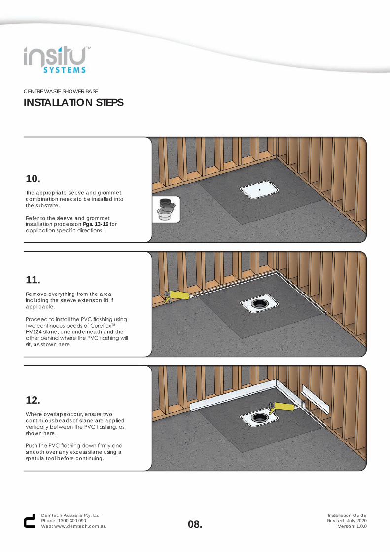
10.The appropriate sleeve and grommetcombination needs to be installed intothe substrate.
Refer to the sleeve and grommet installation process on Pgs. 13-16 for application specific directions.
11.Remove everything from the area including the sleeve extension lid if applicable.
Proceed to install the PVC flashing using two continuous beads of CureflexTM HV124 silane, one underneath and the other behind where the PVC flashing will sit, as shown here.
12.Where overlaps occur, ensure twocontinuous beads of silane are appliedvertically between the PVC flashing, asshown here.
Push the PVC flashing down firmly andsmooth over any excess silane using aspatula tool before continuing.
08.Demtech Australia Pty. LtdPhone: 1300 300 090Web: www.demtech.com.au
Installation GuideRevised: July 2020
Version: 1.0.0

CENTRE WASTE SHOWER BASE
INSTALLATION STEPS
13.Follow the CureflexTM TX88 tile adhesiveinstructions to create a mixture with thedesired consitency for the application.
14.Use a 12mm notched trowel to spread the tile adhesive mixture evenly within the shower base area.
Ensure a 20mm space is present between the base of the PVC flashing, the marked perimeter and the tile adhesive. This will prevent the adhesive from oozing out from under the shower base.
15.Install the shower base within the marked perimeter on top of the tile adhesive. Apply even pressure across the shower base to ensure the the adhesive bonds well and provides maximum adhesion.
If applicable, refer to the split shower base installation process on Pgs. 17-18 for application specific directions.
09.Demtech Australia Pty. LtdPhone: 1300 300 090Web: www.demtech.com.au
Installation GuideRevised: July 2020
Version: 1.0.0
CENTRE WASTE SHOWER BASE
INSTALLATION STEPS
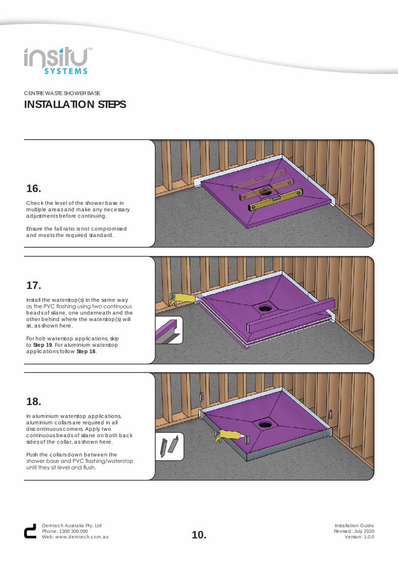
16.Check the level of the shower base inmultiple areas and make any necessaryadjustments before continuing.
Ensure the fall ratio is not compromised and meets the required standard.
17.Install the waterstop(s) in the same way as the PVC flashing using two continuous beads of silane, one underneath and the other behind where the waterstop(s) will sit, as shown here.
For hob waterstop applications, skip to Step 19. For aluminium waterstop applications follow Step 18.
18.In aluminium waterstop applications, aluminium collars are required in all discontinuous corners. Apply two continuous beads of silane on both back sides of the collar, as shown here.
Push the collars down between the shower base and PVC flashing/waterstop until they sit level and flush.
10.Demtech Australia Pty. LtdPhone: 1300 300 090Web: www.demtech.com.au
Installation GuideRevised: July 2020
Version: 1.0.0
CENTRE WASTE SHOWER BASE
INSTALLATION STEPS
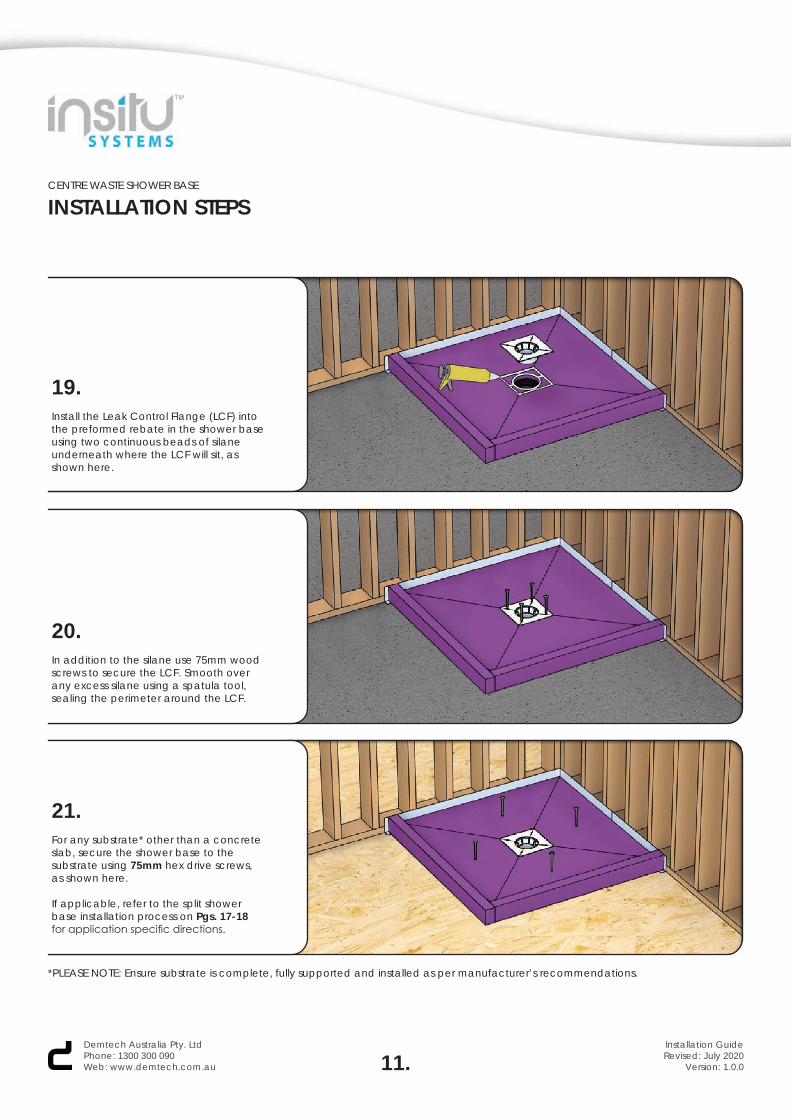
19.Install the Leak Control Flange (LCF) into the preformed rebate in the shower base using two continuous beads of silane underneath where the LCF will sit, as shown here.
20.In addition to the silane use 75mm woodscrews to secure the LCF. Smooth overany excess silane using a spatula tool,sealing the perimeter around the LCF.
21.For any substrate* other than a concrete slab, secure the shower base to the substrate using 75mm hex drive screws, as shown here.
If applicable, refer to the split shower base installation process on Pgs. 17-18 for application specific directions.
11.Demtech Australia Pty. LtdPhone: 1300 300 090Web: www.demtech.com.au
Installation GuideRevised: July 2020
Version: 1.0.0
*PLEASE NOTE: Ensure substrate is complete, fully supported and installed as per manufacturer’s recommendations.
CENTRE WASTE SHOWER BASE
INSTALLATION STEPS
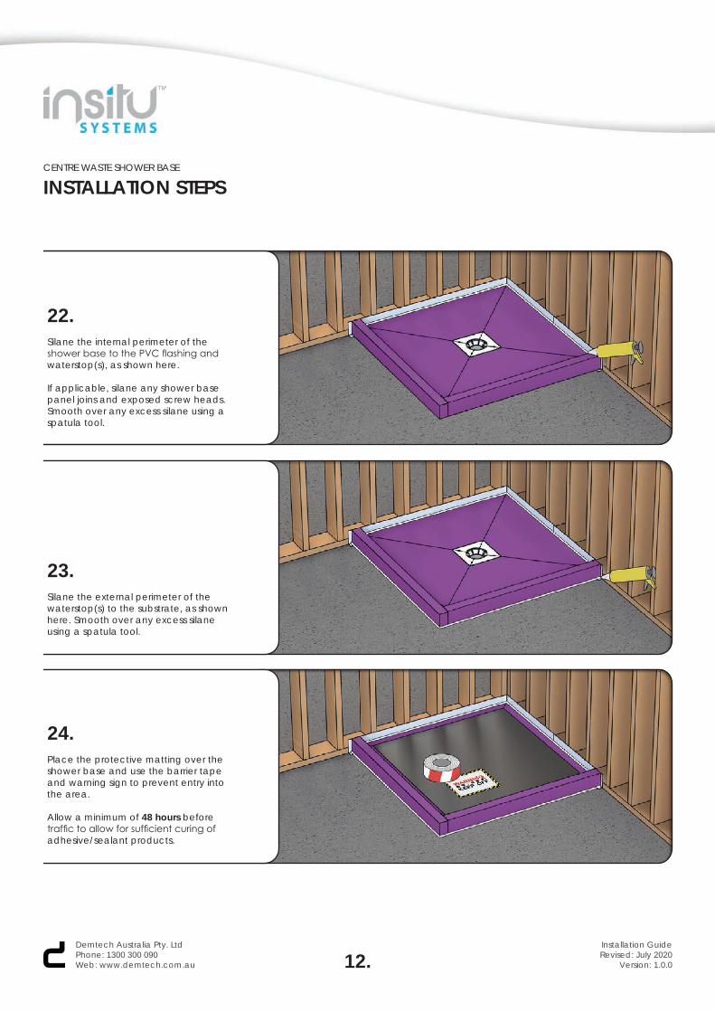
22.Silane the internal perimeter of the shower base to the PVC flashing and waterstop(s), as shown here.
If applicable, silane any shower base panel joins and exposed screw heads. Smooth over any excess silane using a spatula tool.
23.Silane the external perimeter of the waterstop(s) to the substrate, as shown here. Smooth over any excess silane using a spatula tool.
24.Place the protective matting over the shower base and use the barrier tape and warning sign to prevent entry into the area.
Allow a minimum of 48 hours before traffic to allow for sufficient curing of adhesive/sealant products.
12.Demtech Australia Pty. LtdPhone: 1300 300 090Web: www.demtech.com.au
Installation GuideRevised: July 2020
Version: 1.0.0

CENTRE WASTE SHOWER BASE
SLEEVE & GROMMETGROUND FLOOR DESIGN VARIATION
01.Measure and mark where the centre of the shower base waste outlet will sit on the NeroTM Delta Drain using a pencil or marker, if not already marked.
02.Using an 133mm hole saw drill a hole where marked into the plastic/structural lid of the NeroTM Delta Drain.
03.Install a 100mm Sleeve into the NeroTM Delta Drain using one continuous bead of silane underneath, as shown here.
13.Demtech Australia Pty. LtdPhone: 1300 300 090Web: www.demtech.com.au
Installation GuideRevised: July 2020
Version: 1.0.0
CENTRE WASTE SHOWER BASE
SLEEVE & GROMMETGROUND FLOOR DESIGN VARIATION
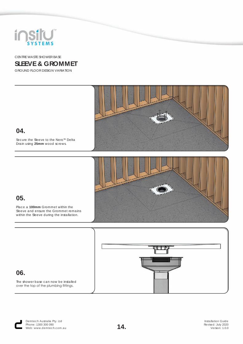
04.Secure the Sleeve to the NeroTM Delta Drain using 25mm wood screws.
05.Place a 100mm Grommet within the Sleeve and ensure the Grommet remains within the Sleeve during the installation.
14.Demtech Australia Pty. LtdPhone: 1300 300 090Web: www.demtech.com.au
Installation GuideRevised: July 2020
Version: 1.0.0
06.The shower base can now be installed over the top of the plumbing fittings.

CENTRE WASTE SHOWER BASE
SLEEVE & GROMMETFIRST FLOOR DESIGN VARIATION
01.Measure and mark where the centre of the shower base waste outlet will sit on the substrate* using a pencil or marker, if not already marked.
02.Using a 133mm hole saw drill a hole where marked into the substrate.
03.Install a 100mm Sleeve Extension into the substrate using one continuous bead of silane underneath, as shown here.
15.Demtech Australia Pty. LtdPhone: 1300 300 090Web: www.demtech.com.au
Installation GuideRevised: July 2020
Version: 1.0.0
*PLEASE NOTE: Ensure substrate is complete, fully supported and installed as per manufacturer’s recommendations.
CENTRE WASTE SHOWER BASE
SLEEVE & GROMMETFIRST FLOOR DESIGN VARIATION
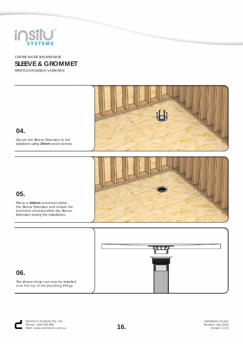
04.Secure the Sleeve Extension to the substrate using 25mm wood screws.
05.Place a 100mm Grommet within the Sleeve Extension and ensure the Grommet remains within the Sleeve Extension during the installation.
16.Demtech Australia Pty. LtdPhone: 1300 300 090Web: www.demtech.com.au
Installation GuideRevised: July 2020
Version: 1.0.0
06.The shower base can now be installed over the top of the plumbing fittings.
CENTRE WASTE SHOWER BASE
TONGUE & GROOVESPLIT SHOWER BASE DESIGN VARIATION
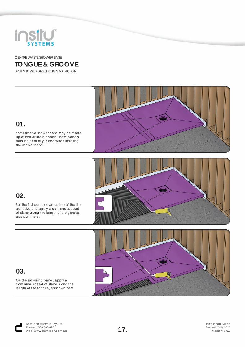
01.Sometimes a shower base may be made up of two or more panels. These panels must be correctly joined when installing the shower base.
02.Set the first panel down on top of the tile adhesive and apply a continuous bead of silane along the length of the groove, as shown here.
03.On the adjoining panel, apply a continuous bead of silane along the length of the tongue, as shown here.
17.Demtech Australia Pty. LtdPhone: 1300 300 090Web: www.demtech.com.au
Installation GuideRevised: July 2020
Version: 1.0.0
CENTRE WASTE SHOWER BASE
TONGUE & GROOVESPLIT SHOWER BASE DESIGN VARIATION
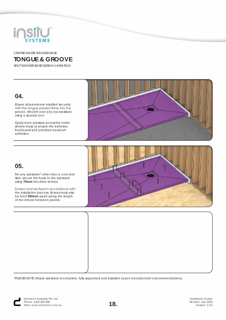
04.Ensure all panels are installed securely with the tongue pressed firmly into the groove. Smooth over any excess silane using a spatula tool.
Apply even pressure across the entire shower base to ensure the adhesive bonds well and provides maximum adhesion.
05.For any substrate* other than a concrete slab, secure the base to the substrate using 75mm hex drive screws.
Screws must be fixed in accordance with the installation process. Screws must also be fixed 300mm apart along the length of the rebate between panels.
18.Demtech Australia Pty. LtdPhone: 1300 300 090Web: www.demtech.com.au
Installation GuideRevised: July 2020
Version: 1.0.0
*PLEASE NOTE: Ensure substrate is complete, fully supported and installed as per manufacturer’s recommendations.
CENTRE WASTE SHOWER BASE
INSTALLATION GUIDE