Linear Drainage - Wade International Ltd.wadedrainage.co.uk/download/linear.pdf · In these cases...
28
November 2016 Uniclass EPIC CI/SfB Linear Drainage
Transcript of Linear Drainage - Wade International Ltd.wadedrainage.co.uk/download/linear.pdf · In these cases...

November 2016
Uniclass EPIC
CI/SfB
Linear Drainage

A privately owned UK company with more than fifty years’ experience in the industry, Wade is established as a leading manufacturer of quality drainage products.
Much of the success of the business is attributable to an on-going commitment to put technology to practical use, to generate fresh ideas, and to guarantee quality assured production.
This Technical Handbook presents illustrations and data from a comprehensive range of products which provide choices to enable specifier and users to select products that will meet their requirements.
Certification of compliance with BS EN ISO 9001 underlines our commitment to quality and service. ISO 9001
3
Contents
Typical applications 4 – 7
Typical installations 8
Channel gratings 9 – 13
Aluminium 12
Cast iron and ductile iron 13
Nickel bronze 12
Stainless steel 10 – 11
Custom-made channel, stainless steel 14 – 19
Curved channel 23
Access covers with linear drainage 15, 20 – 21
Dropped sump 18
Dual-level drainage 19
Gullies with linear drainage 16 – 17
Outlets 16 – 18
Threshold drainage 15, 20 – 21
Custom-made slotted channel, stainless steel 20 – 22
Hidden channel 20
Hidden for threshold drainage 21
Supaslot channel 22
Modular channel, stainless steel
Ductile iron grating 24
Specialised applications
Fire-fighting lift drainage 23
Angle frame, stainless steel 23
Tree grille 26
Installation guidelines 24 – 25
Accessories 26
Load rating classes 27
Materials/care and maintenance 27
Spec. Code index 27
BS EN 1433 and CE marking
Products of the types and sizes stated in this catalogue have third party certification of conformance to BS EN 1433 and are supplied with marking to indicate this, plus a CE mark.
Wade can also supply products of different types and sizes to suit customer requirements, which when subjected to the same tests, may be found also to conform to BS EN 1433, but these will bear the CE mark. Such products must be tested before being placed on the market.
4
TYPICAL APPLICATIONS
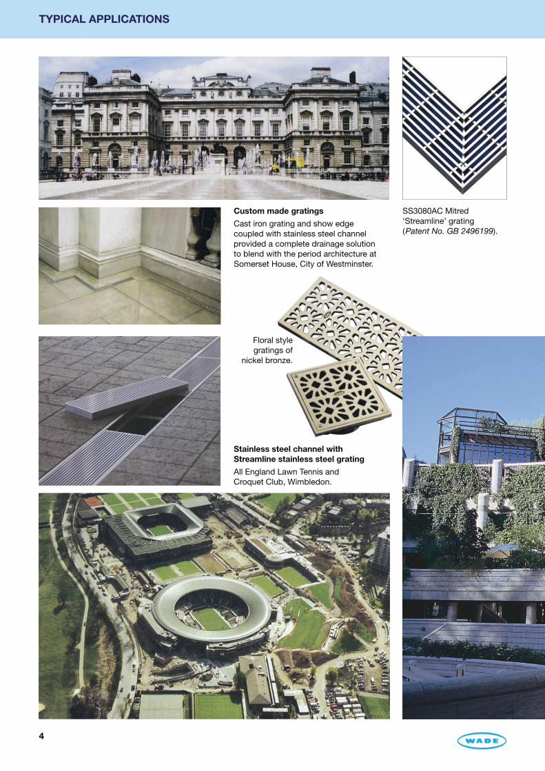
Custom made gratings
Cast iron grating and show edge coupled with stainless steel channel provided a complete drainage solution to blend with the period architecture at Somerset House, City of Westminster.
Stainless steel channel with Streamline stainless steel grating
All England Lawn Tennis and Croquet Club, Wimbledon.
Floral style gratings of
nickel bronze.
SS3080AC Mitred ‘Streamline’ grating (Patent No. GB 2496199).

5
TYPICAL APPLICATIONS
In addition to offering a wide range of standard products, Wade designs and manufactures custom made products to suit particular applications.
Recent projects include banks, hospitals, hotels, laboratories, leisure centres, municipal buildings, museums, private residences and sports arenas.
Availability of faceted and curved channel systems extends choice for specifiers.
Stainless steel channel with nickel bronze grating, Broadgate, City of London
Nickel bronze is equally suitable for inside or outside applications. Aesthetic yet practical nickel bronze complements a wide variety of floor finishes including terrazzo, York stone paviors, marble and sheet floor covering.
Curved NE profile stainless steel channel with curved perforated stainless steel gratings combine function with design.
Typical installation in a vinyl covered floor
SN12230 grating with SVFB channel. Channel profile SVF ensures watertight connection when used with flexible sheet material such as vinyl flooring. Suffix ‘B’ on channel Spec. Code denotes filter bucket.
6
TYPICAL APPLICATIONS
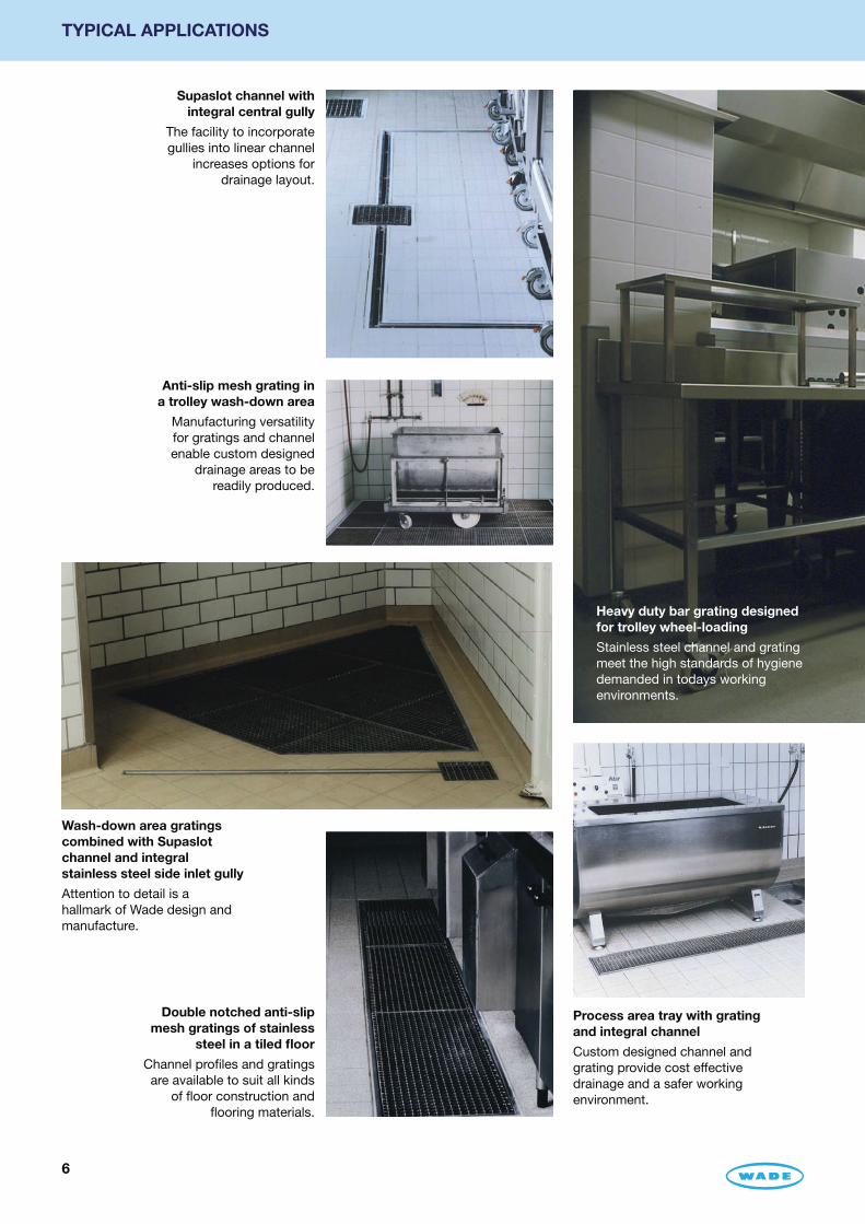
Supaslot channel with integral central gully
The facility to incorporate gullies into linear channel
increases options for drainage layout.
Anti-slip mesh grating in a trolley wash-down area
Manufacturing versatility for gratings and channel enable custom designed
drainage areas to be readily produced.
Wash-down area gratings combined with Supaslot channel and integral stainless steel side inlet gully
Attention to detail is a hallmark of Wade design and manufacture.
Double notched anti-slip mesh gratings of stainless
steel in a tiled floor
Channel profiles and gratings are available to suit all kinds
of floor construction and flooring materials.
Process area tray with grating and integral channel
Custom designed channel and grating provide cost effective drainage and a safer working environment.
Heavy duty bar grating designed for trolley wheel-loading
Stainless steel channel and grating meet the high standards of hygiene demanded in todays working environments.

7
TYPICAL APPLICATIONS
Heavy duty plain mesh grating for high volume areas
Standard and custom made grating and channel are available to withstand the arduous conditions often experienced in industrial processing.
Double notched anti-slip grating
In areas where high volumes of water may be discharged, anti-slip gratings with generous free area provide extra safety for personnel.
Wash-down channel tray and Supaslot channel with integral stainless steel gully
Stainless steel gullies with side inlets when used with channel drainage eliminate the need for separate drain runs.
Reverse wedge profile of Streamline
stainless steel grating reduces incidence
of blockages.

8
TYPICAL INSTALLATIONS OF CUSTOM-MADE CHANNEL WITH GRATING
NE channel and SS5135B5 grating, shown with Q21 style 2” BSP horizontal side outlet and U1404 removable bottle trap.
RP channel and SN12230 grating, with G304LD ‘P’ trapped body (supplied with channel sealing kit).
SVF channel and SS40135A1 grating, spaced away from wall, vinyl dressed both sides.
NEF channel and SS7300A5 grating with Q14 style dropped sump and U1704 removable bell trap.
RE channel and SS3135A5 grating with D1004 non-trapped body and C.D10LW membrane clamping collar.
SVFT channel (SVF with optional tile upstand) and SS40135A1 grating.
Shown below are some typical installations; there are many other permutations. Please refer to the following pages to select the grating, channel profile and options.

9
CHANNEL GRATINGS
CE regulations/product standards/BS EN 1433Standard channel and gratings shown in the following pages have been type-tested under the supervision of BSI (British Standards Institution) and conform to BS EN 1433.
Given the enormous quantity of possible grating sizes combined with different load bars that deliver different load classes, it is not practicable or economic to have third party certification for every custom-made grating. Accordingly, Wade has its own testing facilities at Halstead to enable testing, as laid down in BS EN 1433, and the application of CE status to the items that conform.
In response to customer demand, Wade manufactures some gratings that do not conform to BS EN 1433. These are not defective in any way, but, for example, some customers require gratings for pedestrian areas with a slot width of 4mm, whereas BS EN 1433 sets a minimum slot width of 5mm in such places. In these cases the gratings are tested by Wade and the CE mark is applied to denote the essential requirements are met. Only one such grating is illustrated in this catalogue – SN23130.
Grating sizesSizes stated are nominal, not precise measurements, as gratings are manufactured to fit the ordered channel or angle frame with allowance to enable removal of gratings. Stainless steel gratings are made to length; where multiple cast gratings do not fit the channel one or more gratings are cut to length.
Grating load class per BS EN 1433Load class is when installed in channel of the same or higher load class in accordance with Wade installation instructions; see pages 24 and 27.
Grating availability/delivery Standard versions, shown in the following pages, are generally available ex stock; other sizes can be made to order. Gratings are fitted into the ordered channel or angle frame at our factory and are so delivered. Gratings may not always be interchangeable, so it is good practice to return to original position in the length of channel/angle frame.
Secured gratingsAs standard, gratings are lain loose in channel or angle frame. As an option, gratings may be secured (locked) to the channel or angle frame – add suffix ‘L’ to the grating Spec. Code. Pin-Torx or Pin-Hex screws are fitted on all locked gratings, making them suitable for security applications.
10
CHANNEL GRATINGS – BS EN 1433 COMPLIANT
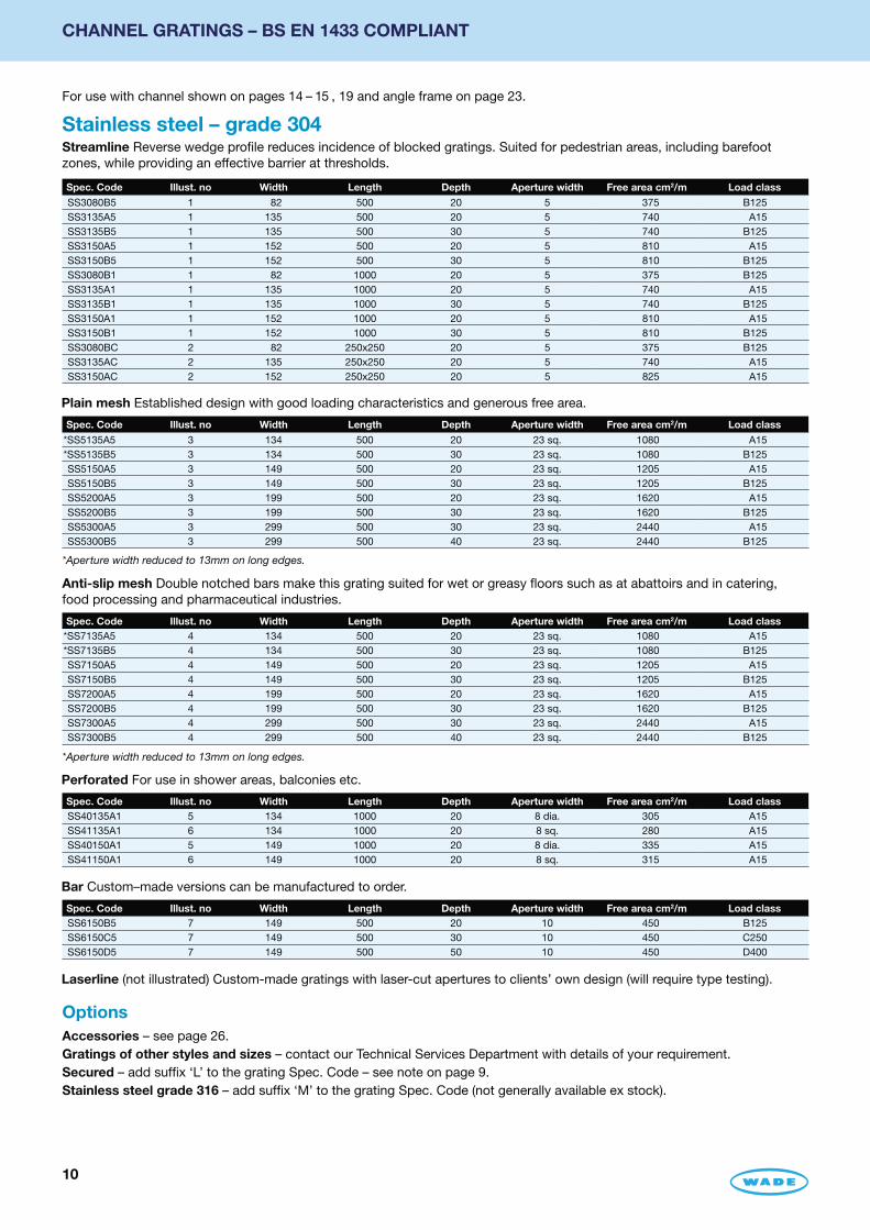
Spec. Code Illust. no Width Length Depth Aperture width Free area cm2/m Load class
SS3080B5 1 82 500 20 5 375 B125SS3135A5 1 135 500 20 5 740 A15SS3135B5 1 135 500 30 5 740 B125SS3150A5 1 152 500 20 5 810 A15SS3150B5 1 152 500 30 5 810 B125SS3080B1 1 82 1000 20 5 375 B125SS3135A1 1 135 1000 20 5 740 A15SS3135B1 1 135 1000 30 5 740 B125SS3150A1 1 152 1000 20 5 810 A15SS3150B1 1 152 1000 30 5 810 B125SS3080BC 2 82 250x250 20 5 375 B125SS3135AC 2 135 250x250 20 5 740 A15SS3150AC 2 152 250x250 20 5 825 A15
Spec. Code Illust. no Width Length Depth Aperture width Free area cm2/m Load class
*SS5135A5 3 134 500 20 23 sq. 1080 A15*SS5135B5 3 134 500 30 23 sq. 1080 B125SS5150A5 3 149 500 20 23 sq. 1205 A15SS5150B5 3 149 500 30 23 sq. 1205 B125SS5200A5 3 199 500 20 23 sq. 1620 A15SS5200B5 3 199 500 30 23 sq. 1620 B125SS5300A5 3 299 500 30 23 sq. 2440 A15SS5300B5 3 299 500 40 23 sq. 2440 B125
Plain mesh Established design with good loading characteristics and generous free area.
Spec. Code Illust. no Width Length Depth Aperture width Free area cm2/m Load classSS40135A1 5 134 1000 20 8 dia. 305 A15SS41135A1 6 134 1000 20 8 sq. 280 A15SS40150A1 5 149 1000 20 8 dia. 335 A15SS41150A1 6 149 1000 20 8 sq. 315 A15
Perforated For use in shower areas, balconies etc.
Spec. Code Illust. no Width Length Depth Aperture width Free area cm2/m Load classSS6150B5 7 149 500 20 10 450 B125SS6150C5 7 149 500 30 10 450 C250SS6150D5 7 149 500 50 10 450 D400
Bar Custom–made versions can be manufactured to order.
Laserline (not illustrated) Custom-made gratings with laser-cut apertures to clients’ own design (will require type testing).
Spec. Code Illust. no Width Length Depth Aperture width Free area cm2/m Load class*SS7135A5 4 134 500 20 23 sq. 1080 A15*SS7135B5 4 134 500 30 23 sq. 1080 B125SS7150A5 4 149 500 20 23 sq. 1205 A15SS7150B5 4 149 500 30 23 sq. 1205 B125SS7200A5 4 199 500 20 23 sq. 1620 A15SS7200B5 4 199 500 30 23 sq. 1620 B125SS7300A5 4 299 500 30 23 sq. 2440 A15SS7300B5 4 299 500 40 23 sq. 2440 B125
Anti-slip mesh Double notched bars make this grating suited for wet or greasy floors such as at abattoirs and in catering, food processing and pharmaceutical industries.
OptionsAccessories – see page 26.Gratings of other styles and sizes – contact our Technical Services Department with details of your requirement.Secured – add suffix ‘L’ to the grating Spec. Code – see note on page 9.Stainless steel grade 316 – add suffix ‘M’ to the grating Spec. Code (not generally available ex stock).
For use with channel shown on pages 14 – 15 , 19 and angle frame on page 23.
Stainless steel – grade 304Streamline Reverse wedge profile reduces incidence of blocked gratings. Suited for pedestrian areas, including barefoot zones, while providing an effective barrier at thresholds.
*Aperture width reduced to 13mm on long edges.
*Aperture width reduced to 13mm on long edges.

11
CHANNEL GRATINGS – BS EN 1433 COMPLIANT
Streamline
Plain mesh
Anti-slip mesh
Perforated
Perforated
Bar
Streamline(mitred corner)
†
1
3
4
5
6
7
2
† Patent No. GB 2496199

12
CHANNEL GRATINGS – BS EN 1433 COMPLIANT
1
2
3
4
5
6
7
8
OptionsGratings of other styles and sizes – contact our Technical Services Department with details of your requirement. Secured – add suffix ‘L’ to the grating Spec. Code. Not available with SN11230, SN16330, SA16330 – see note on page 9.
Spec. Code Illust. no Width Length Depth Aperture width Free area cm2/m Load class
SN11230 1 60 495 15 10 172 B125SN11430 2 60 496 15 16 sq. 184 B125SN12220 3 115 544 10 8 365 B125SN12230 3 134 662 15 8 425 A15SN13240 4 186 485 20 10 725 A15SN16330 8 300 483 15 12 1440 A15
Floral
Spec. Code Illust. no Width Length Depth Aperture width Free area cm2/m Load class
SN23930 6 149 499 15 15 max 475 A15SN25930 7 293 499 15 15 max 950 A15
SN23130 does not conform with BS EN 1433 because the slot size of 4mm is below the minimum of 5mm set in the standard. The grating conforms with CE regulations and bears the CE mark.
Decorative – A matching tree grille S4604 also available (see page 26).Spec. Code Illust. no Width Length Depth Aperture width Free area cm2/m Load class
SN23130 5 150 499 15 4 280 A15
Aluminium BS EN 1706Gratings for use in low priority pedestrian areas.Standard apertureSpec. Code Illust. no Width Length Depth Aperture width Free area cm2/m Load class
SA12220 3 115 544 10 8 365 A15SA12230 3 134 662 15 8 425 A15SA16330 8 300 483 15 12 1440 A15
For use with channel shown on pages 14 –15, 19 and angle frame on page 23.
Nickel bronze BS EN 1982 – satin finishDurable high quality gratings particularly suited to areas subject to a high volume of pedestrian traffic.Standard aperture

13
CHANNEL GRATINGS – BS EN 1433 COMPLIANT
1
2
3
4
5
6
7
8
9
Sherardized ductile iron – BS EN 1563 and 1564
Spec. Code Illust. no Width Length Depth Aperture width Free area cm2/m Load class
SC11230 1 60 497 16 10 172 B125SC11430 2 60 500 15 16 sq. 184 B125SC12220 3 115 544 10 8 365 A15SC12330 4 143 387 12 11 425 B125SC12431 5 149 497 15 16 sq. 470 B125SC23930 6 149 499 16 15 max. 475 A15
Spec. Code Illust. no Width Length Depth Aperture width Free area cm2/m Load class
SG15350 8 251 251 23 12 1180 B125SG16250 9 305 305 26 9 970 A15SG16460 7 305 610 26 16 1240 C250
OptionsGratings of other styles and sizes – contact our Technical Services Department with details of your requirement.Secured – add suffix ‘L’ to the grating Spec. Code. Not available with SC11230 – see note on page 9.
For use with channel shown on pages 14 –15, 19 and angle frame on page 23.
Cast ironRobust durable gratings for use in service areas, plant areas and for restoration or refurbishment projects to match period architecture.
Sherardized cast iron – BS EN 1561

14
CUSTOM-MADE CHANNEL – BS EN 1433 COMPLIANT
For use with gratings shown on pages 10 –13.
Stainless steel – grade 304, (min.) 1.5mm thickness
Narrow edgeNarrow show edge, suitable for most standard applications, provides a floor finish abutment face; can be produced as a curved channel with any of the perforated gratings listed on page 10, (see example on page 5).
Narrow edge, heavy dutyNot suitable for hygiene environments. Load class D400 is also available, with 5mm wide show edge – add suffix D400 to Spec. Code.
Narrow edge, flangedNot suitable for hygiene environments. Load class A15 in timber deck. Narrow show edge provides a floor finish abutment face. Extended flange enables dressing a membrane and/or fixing to a timber deck (Fixing holes are available on request). When specifying/ordering please advise the required flange depth.
Regular profileSuitable for most standard applications. Load class D400 also available (2mm channel thickness) – add suffix D400 to Spec. Code.
Return edgeAdditional fold provides extra stability to channel edge and a floor finish abutment face. Load class D400 also available (2mm channel thickness) – add suffix D400 to Spec. Code. A support bar is recommended in C250 and D400 applications.
Support edge Provides facility to receive and support floor finish. Load class D400 also available (2mm channel thickness) – add suffix D400 to Spec. Code. A support bar is recommended in C250 and D400 applications.
Perimeter angle frame Helps prevent breakage of floor finish alongside the channel edge where heavy loads may be present. Load class D400 also available (2mm channel thickness) – add suffix D400 to Spec. Code. A support bar is recommended in C250 and D400 applications.
For use with vinyl and other flexible sheet materialStainless steel clamp ensures watertight connection, access to channel and outlet is easily achieved without disturbing the floor covering. Minimum grating width required = 80mm.
For use with vinyl and other flexible sheet material Has an extended flange with fixing holes, for use in timber deck.
For use with flexible sheet floor covering in heavy duty environments profile RP is available with a factory fitted, PVC angle edging strip to which sheet floor covering can be butt-welded at the time of installation; such channels are particularly suited to heavy duty applications. Note: Suitable only for channels with grating of minimum 25mm depth.
Note: For optional tile upstand, add suffix ‘T’, see page 8.
Channel is available in a range of profiles, shown and described below, generally with in-built fall towards the outlets. Side bars and folds are made so that the selected grating fits flush with the show edges. Load class is when installed with grating of same or higher class in accordance with Wade installation guidelines, see pages 24 and 25.
Spec. Code: NELoad Class: B125Show edge = 3mm
Spec. Code: NEHDLoad Class: C250Show edge = 3mm
Spec. Code: NEFLoad Class: C250Show edge = 3mmFlange = 50mm
Spec. Code: RPLoad Class: C250Show flange = 10mm
Spec. Code: RELoad Class: C250Show flange = 25mm
Spec. Code: SELoad Class: C250Show flange = 25mm
Spec. Code: PALoad Class: C250Show flange = 25mm
Spec. Code: SVFLoad Class: A15Show flange = 15mm
Spec. Code: SVFELoad Class: A15Show flange = 15mmFixing flange = 50mm
Spec. Code: RPVLoad class: C250Show flange = 27mm

15
CUSTOM-MADE CHANNEL – BS EN 1433 COMPLIANT
Stainless steel – grade 304,(min.) 1.5mm thickness
For use with gratings shown on pages 10 –13.
Typical straight channel – key dimensionsSVF profile shown, also applicable to all profiles illustrated opposite.
OptionsAccessoriesPush-in removable bottle trap, filter bucket and other accessories detailed on page 26.
Dropped sump – to help improve drainage or allow an optional large stainless steel filter bucket/removable trap. See page 18 for details.
Dual-level drainage – enables secondary drainage at membrane level. See page 19 for details. Add suffix SSD, DSD (single or double).
Grade 316 stainless steel – for increased corrosion resistance – add suffix ‘M’ to channel Spec. Code.
Gully body – see Outlets page 16 –17.As well as connecting directly to pipework, stainless steel drainage channel may also be used with Wade Floor Gullies, trapped or untrapped as illustrated on page 8 and 16.
Support bar – a solid stainless steel support bar helps prevent deformation or movement of channel show flange in heavy load bearing areas. To specify/order – add suffix ‘S’ to the channel Spec. Code. (May be used with channel profiles: RP, RE, SE, PA or RPV).
Tile upstand – for tiling over, or for use with other finishes and/or membrane where channel is being installed close to a tiled wall, (see illustration on page 8) 70mm high unless otherwise specified. Add suffix ‘T’.
To obtain a quotation, please provide the following:Grating Spec. CodeChannel profile Spec. Code, followed by any required option suffix(es) (see below)General dimensions in mm (A to E above) and layout of channel.Outlet connection details (F above – size/type of pipework system)Thickness of floor finish (where applicable)Gully body Spec. Code or Dropped sump style (if required)Options/Accessories Spec. Code (if required)
(Visible length at FFL)
B (Outlet position)
D (Channel depth at outlet)
E (Outlet spigot length)
(Channel depth at ends;minimum =
grating depth + 15mmSVF + SVFE + 20mm)
F(Size/type of
pipework connection)
A
C
To suit particular applications channel can be custom made in grade 304 or 316, with or without fall, with a combination of different profiles, on the same or opposite side, with non standard profiles including deep invert, ‘V’ bottom and heavy duty versions. Please contact our Technical Services Department for details.
Design considerationsWhen positioning channel adjacent to wall, ensure adequate allowance is made between channel and wall to cater for flooring manufacturer’s edging detail.
Access covers with linear drainageSolid access covers may be fitted in channels where required, e.g. areas where a channel runs beneath equipment or walls. Covers may be secured or non-secured and may be recessed to accept flooring material where depth is sufficient.
Threshold drainageLinear drainage channels provide an ideal solution to the problem of protecting building thresholds from the ingress of surface water. All of the channel profiles shown within this catalogue can be manufactured to suit specific requirements, with slots or gratings at surface level; Wade ‘Streamline’ gratings are particularly suited to this application. Also see pages 20 and 21.
Note: If a channel has more than one outlet and gulliesare to be pre-installed, then accurate dimensions must beestablished. Where possible, gullies should be cast-inusing the channel assembly to determine positions.
Some typical layouts
Straight section
‘T’ section
‘L’ section
‘U’ section

16
CHANNEL OUTLETS
Gully body with channel sealing kitChannel is made with a welded-on outlet, as above, that is push fitted into the body on site when the channel sealing kit is in position. Approximately 10mm of height adjustability is available. The collar can also be used to clamp a membrane if used. Illustrated is a selection of bodies regularly used with linear drainage.
Trapped – Cast iron
Rodding access plugand seal
2" BSPmax.
Optionalside inletsup to 3 at 90°
Outletto suitBS 416
45
50
'C' 'D''A'
'E'
'B'
115 dia.Clamping collar,cast iron(included)
Seal ring
2" BSPmax.
Rodding accessplug and seal
Outlet to suit BS 416
45
50Optionalside inletsup to 3 at 90°
'C''D'
'E'
'A''B'
115 dia.Clamping collar,cast iron(included)
Seal ring
Rodding access plugand seal
Optional side inlets,up to 3 at 90°2" BSP max.
223 x 220
51
170
20550
102
131
Factory sealedplug
Outlet tosuit BS 416/DIN 19522
111 dia.
115 dia.
Clamping collar,cast iron(included) Seal ring
111 dia.
Factorysealedplug
Outlet tosuit BS 416/DIN 19522
51
205
129
37
50170
Rodding access plugand seal
Optional side inlets,up to 3 at 90°2" BSP max.
223 x 220115 dia.
Clampingcollar,cast iron(included)
Seal ring
G3LD series ‘P’ trapped – 50mm seal
G6LD series ‘S’ trapped – 50mm seal
G804LD ‘P’ trapped – 50mm seal
G1004LD ‘S’ trapped – 50mm seal
Spec. Code
Outlet size A B C D E
Free areacm2 kg
G303LD 75mm 170 80 87 89 185 44 7.8G304LD 100mm 205 92 112 no bead 190 78 9.6G804LD 100mm – – – – – 72 15.4G603LD 75mm 170 150 87 89 145 44 8.5G604LD 100mm 205 165 112 no bead 155 78 11.0G1004LD 100mm – – – – – 72 15.8
The channel sealing kit comprises a neoprene seal ring and a clamp collar with studs, nuts and washers.
Tightening the nuts compresses the ring to form a watertight connection between channel outlet and body.
These can take different forms as described below.
Direct connection outletsChannel is available with welded-on outlet(s) for connecting directly to pipework. Outlets are generally vertical from the base but can be horizontal from the side or end. Spigot outlets (plain pipe 110mm o.d.) have standard length of 90mm.
Longer spigots are available, max. 950mm, are supplied with standard outside diameter of 114 mm for connection to pipework with a coupling.
Outlets smaller than 75mm/3" are generally supplied as a female BSP threaded socket for connection to pipework having a male threaded pipework adaptor.
SVF channel and SS7300A5 grating, vinyl dressed both sides, with G304LD ‘P’ trapped body (supplied with channel sealing kit).
Typical installation

17
CHANNEL OUTLETS
Gully body for use with bituminous membrane Non-trapped – Cast iron
Trapped – Stainless steel grade 304 (for grade 316 add suffix ‘M’ to Spec. Code)
Non-trapped – Stainless steel grade 304 (for grade 316 add suffix ‘M’ to Spec. Code)
QG114LD Vertical outlet (BS 416) – bell trapped QG214LD Horizontal outlet (BS 416) – ‘P’ trapped
Spec. Code
Outlet size mm
Free area cm2
Traptype kg
QG114LD 100 51 Bell 2.8QG214LD 100 60 P 3.5
D10 series Vertical threaded outlet
D12 series Horizontal threaded outlet
D11 series BS 416 spigot outlet
57
305 dia.115 dia.
'B'
'A'195
235 dia.
Gasket
Outlet spigotconformsto BS 416
Membrane clamping collar(required –see table)
7Weephole
57
7
90
195
2", 3" or 4" BSPOutlet thread
235 dia.
305 dia.115 dia.
GasketMembrane clamping collar(required –see table)
Weephole
305 dia.115 dia.
Gasket
'A'
'C'235 dia.
98
2", 3" or 4" BSPOutlet thread
6
57
'B'
Membrane clampingcollar (required –see table)
WeepholeSpec. Code
Body CollarOutlet size A B C
Free areacm2 kg
D1002 C.D10LW 2" BSP – – – 19 5.0D1003 C.D10LW 3" BSP – – – 44 4.3D1004 C.D10LW 4" BSP – – – 78 3.3D1108 C.D10LW 75mm 87 165 – 44 3.7D1109 C.D10LW 100mm 112 190 – 78 8.7D1207 C.D10LW 2" BSP 119 80.5 143 19 6.5D1208 C.D10LW 3" BSP 119 67.5 143 44 6.7D1209 C.D10LW 4" BSP 183 117 91 78 6.5
QB114LD Vertical outlet (BS 416) – deep sump QB214LD Horizontal outlet (BS 416) – deep sump
Spec. Code
Outlet size mm
Free area cm2 kg
QB114LD 100 78 2.3QB214LD 100 78 2.1
To specify/orderSpecify Body and Collar Spec. Code from the table above.
Membrane clamping collar is required, C.D10LW with weepholes. Channel sealing kit is not applicable to D10–D12 series gully bodies.
186
90
110 O.D.
185 dia.
60
Outlet to suitBS 416/DIN 19522/plastic(100mm nominal bore)
Optionalside inletsup to 4 at 90°2" BSP Max
Bell trapassembly
Roddingaccessplug and seal
Gasket seal
Removableupstand
65
115 dia.Clamping collarPVC (included)
Seal ring
111
110 O.D.
256
60
Roddingaccessplug and seal
Optionalside inletsup to 3 at 90°2" BSP Max
Trap
Outlet to suit BS 416/DIN 19522/plastic (100mm nominal bore)
185 dia.
65
115 dia. Seal ringClamping collarPVC (included)
138
110 O.D.
185 dia.
82
Optionalside inletsup to three at 90°2" BSP Max
Outlet to suitBS 416/DIN 19522/plastic(100mm nominal bore)
115 dia. Seal ringClamping collarPVC (included)
140
60
Optionalside inletsup to four at 90°2" BSP Max
Outlet to suitBS 416/DIN 19522/plastic(100mm nominal bore)110 O.D.
185 dia.
115 dia. Seal ringClamping collarPVC (included)
18
DROPPED SUMP CHANNEL OUTLETS
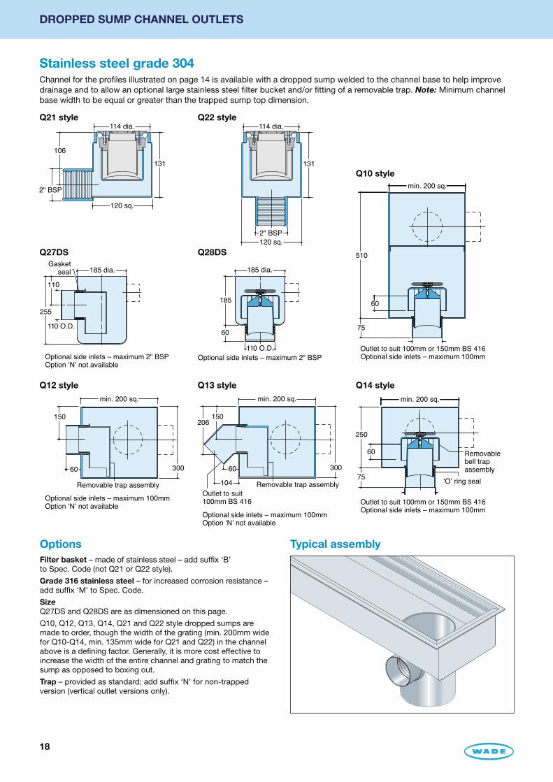
Stainless steel grade 304Channel for the profiles illustrated on page 14 is available with a dropped sump welded to the channel base to help improve drainage and to allow an optional large stainless steel filter bucket and/or fitting of a removable trap. Note: Minimum channel base width to be equal or greater than the trapped sump top dimension.
Q27DS
Q13 style
Q10 style
Q28DS
Q14 styleQ12 style
Outlet to suit100mm BS 416
min. 200 sq.
300
206150
60
104
Optional side inlets – maximum 100mmOption ‘N’ not available
Removable trap assembly
185 dia.
110
110 O.D.
Gasketseal
255
Optional side inlets – maximum 2" BSPOption ‘N’ not available
510
min. 200 sq.
60
75
Outlet to suit 100mm or 150mm BS 416Optional side inlets – maximum 100mm
min. 200 sq.
300
150
60
Optional side inlets – maximum 100mmOption ‘N’ not available
Removable trap assembly
185 dia.
185
60
110 O.D.Optional side inlets – maximum 2" BSP
min. 200 sq.
250
75
60
Outlet to suit 100mm or 150mm BS 416Optional side inlets – maximum 100mm
‘O’ ring seal
Removable bell trapassembly
Typical assemblyOptionsFilter basket – made of stainless steel – add suffix ‘B’ to Spec. Code (not Q21 or Q22 style).
Grade 316 stainless steel – for increased corrosion resistance – add suffix ‘M’ to Spec. Code.
SizeQ27DS and Q28DS are as dimensioned on this page.
Q10, Q12, Q13, Q14, Q21 and Q22 style dropped sumps are made to order, though the width of the grating (min. 200mm wide for Q10-Q14, min. 135mm wide for Q21 and Q22) in the channel above is a defining factor. Generally, it is more cost effective to increase the width of the entire channel and grating to match the sump as opposed to boxing out.
Trap – provided as standard; add suffix ‘N’ for non-trapped version (vertical outlet versions only).
Q21 style Q22 style114 dia.
120 sq.
131
106
2" BSP
114 dia.
120 sq.
131
2" BSP

19
CUSTOM-MADE CHANNEL – DUAL LEVEL – BS EN 1433 COMPLIANT
Grating (Select from page 10 –13) Sand/bedding PaviorTile
Screed
Membrane
Geo-textilemembrane
Drainage slots
Grating (Select from page 10 –13) Sand/bedding Pavior
Membrane
Geo-textilemembrane
Drainage slots
Geo-textilemembrane
To specify/order:Grating Spec. Code
Channel profile Spec. Code
Secondary drainage Spec. Code (SSD or DSD)
General dimensions in mm and layout of channel
Outlet connection details
Membrane depth from finished floor level
Gully body Spec. Code or dropped sump style (if required)
Accessories Spec. Code (if required)
Provides primary drainage at finished floor level plus secondary drainage at membrane level. Suitable for installation in pedestrian and light vehicular areas only.
Secondary drainage is available with the channel profiles shown on pages 14 and 20, for use with gratings shown on pages 10 – 13.
Load class: A15
Single secondary drainage (SSD) with channel profile NE
Stainless steel – grade 304, (min.) 1.5mm thickness
Typical installations
Double secondary drainage (DSD) with channel profile NE
20
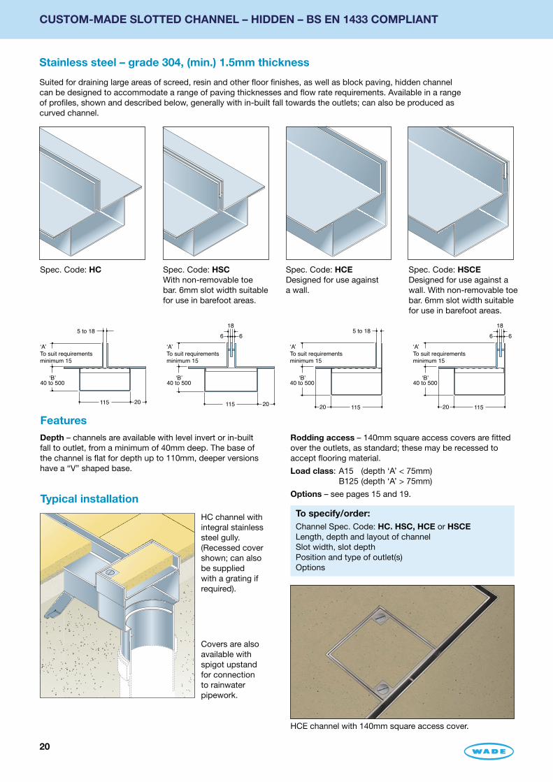
CUSTOM-MADE SLOTTED CHANNEL – HIDDEN – BS EN 1433 COMPLIANT
Stainless steel – grade 304, (min.) 1.5mm thickness
Suited for draining large areas of screed, resin and other floor finishes, as well as block paving, hidden channel can be designed to accommodate a range of paving thicknesses and flow rate requirements. Available in a range of profiles, shown and described below, generally with in-built fall towards the outlets; can also be produced as curved channel.
HC channel with integral stainless steel gully. (Recessed cover shown; can also be supplied with a grating if required).
Covers are also available with spigot upstand for connection to rainwater pipework.
Spec. Code: HC Spec. Code: HSCWith non-removable toe bar. 6mm slot width suitable for use in barefoot areas.
Depth – channels are available with level invert or in-built fall to outlet, from a minimum of 40mm deep. The base of the channel is flat for depth up to 110mm, deeper versions have a “V” shaped base.
Spec. Code: HCEDesigned for use against a wall.
Spec. Code: HSCEDesigned for use against a wall. With non-removable toe bar. 6mm slot width suitable for use in barefoot areas.
To specify/order:Channel Spec. Code: HC. HSC, HCE or HSCELength, depth and layout of channelSlot width, slot depthPosition and type of outlet(s)Options
Typical installation
Features
5 to 18
115 20
‘B’40 to 500
‘A’To suit requirementsminimum 15
18
6 6
‘B’40 to 500
‘A’To suit requirementsminimum 15
115 20
5 to 18
20 115
‘B’40 to 500
‘A’To suit requirementsminimum 15
‘B’40 to 500
20 115
‘A’To suit requirementsminimum 15
18
6 6
Rodding access – 140mm square access covers are fitted over the outlets, as standard; these may be recessed to accept flooring material.
Load class: A15 (depth ‘A’ < 75mm) B125 (depth ‘A’ > 75mm)
Options – see pages 15 and 19.
HCE channel with 140mm square access cover.

21
CUSTOM-MADE SLOTTED CHANNEL – HIDDEN FOR THRESHOLD DRAINAGE BS EN 1433 COMPLIANT
Stainless steel – grade 304, (min.) 2mm thickness
To help protect a building threshold from ingress/ponding of rainwater landing on an external door, the specially formed channel is installed, generally, 10mm away from the door cill, this gap being the path for rainwater to flow into the hidden channel below. The channel also has facility to receive run-off from a sub-cill and/or from the damp proof course/membrane that must be dressed into the channel.
Spec. Code: TDN Spec. Code: TDR with 50mm show face
Typical installation
130
‘B’75 to 110
‘A’25 to 75
‘D’Generally
10
50
115
Optional horizontal2" BSP female outlet
2" BSP female outlet with T1702 adaptor to 50mm plastic pipe
‘C’0 to 20
76 sq.
Optional horizontal2" BSP female outlet
2" BSP female outlet with T1702 adaptor to 50mm plastic pipe
130
‘B’75 to 110
‘A’25 to 75
‘D’Generally
10
76 sq.50
115
‘C’0 to 20
OptionsGrade 316 stainless steel – add suffix ‘M’ to the channel Spec. Code
Outlet – 2” BSP with T1702 ABS adaptor to 50mm plastic pipe supplied as standard. Larger outlets may be specified.
Recessed access cover – 76mm square c/w lifting bosses over outlet.
To specify – quote Spec. Code: TDN or TDR.
To obtain a quotation, please provide the following:Spec. Code: TDN or TDROverall length – in mm, and layout of channelOutlet – quantity on each runAccess cover – quantity (generally one over each outlet).
The following additional information will be required to process an order:Dimensions A-D in mmOutlet/recessed access cover positions along each runOutlet type (horizontal or vertical)Level or in-built falls to base of channel.
Sub-cill and/or membrane dressed into channel

22
CUSTOM-MADE SLOTTED CHANNEL – SUPASLOT – BS EN 1433 COMPLIANT
Stainless steel – grade 304, (min.) 1.5mm thickness
Supaslot channels are suited for large areas with only low volumes of waste water such as in abattoirs, butcheries, dairies, breweries etc. Neat and unobtrusive, the channels are a popular choice as a barrier between designated wet
and dry zones, such as between dishwashing and cooking areas of a kitchen.
Spec. Code: SL
Spec. Code: SSLWith non-removable toe bar. 6mm slot width suitable for use in barefoot areas
Spec. Code: HLDesigned for use against a wall
Features• depth from 65mm to 180mm with or without fall
• suitable for tiled and resin floors
• easily cleaned by directing jet of water along the channel towards the outlet
• can be combined with Wade gullies and channel gratings
Load class: B125
OptionsGrade 316 stainless steel – for increased corrosion resistance – add suffix ‘M’ to channel Spec. Code.
To special order, stainless steel gullies can be welded anywhere along the channel. Gullies may be trapped (‘P’ or bell) if required.
Support bar – a solid stainless steel support bar helps prevent deformation or movement of channel show flange in heavy load bearing areas. To specify/order – add suffix ‘S’ to the channel Spec. Code.
Please contact our Technical Services Department for details.
SL Channel with integral stainless steel gully.(Gully grating omitted for clarity, can also be supplied with a recessed cover if required).
To specify/order:Spec. Code SL, SSL or HL, length, depth and layout of channel, position and diameter of outlet.
Typical installation
Section: SL Section: SSL Section: HL
5418
20 12
65 min.
68
180max.
54
20 12
65 min.
68
180max.
6 6
3720
20
80
10
65 -180
45
23
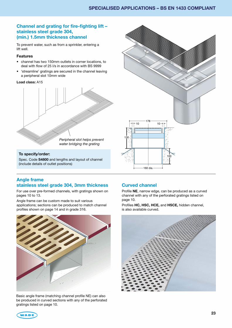
SPECIALISED APPLICATIONS – BS EN 1433 COMPLIANT
Channel and grating for fire-fighting lift – stainless steel grade 304,(min.) 1.5mm thickness channel
Angle frame stainless steel grade 304, 3mm thickness
Curved channel
To prevent water, such as from a sprinkler, entering a lift well.
Features• channel has two 150mm outlets in corner locations, to
deal with flow of 25 l/s in accordance with BS 9999
• ‘streamline’ gratings are secured in the channel leaving a peripheral slot 10mm wide
Load class: A15
For use over pre-formed channels, with gratings shown on pages 10 to 13.
Angle frame can be custom made to suit various applications; sections can be produced to match channel profiles shown on page 14 and in grade 316.
Profile NE, narrow edge, can be produced as a curved channel with any of the perforated gratings listed on page 10.
Profiles HC, HSC, HCE, and HSCE, hidden channel, is also available curved.
Peripheral slot helps prevent water bridging the grating
To specify/order:Spec. Code S4800 and lengths and layout of channel (include details of outlet positions)
Basic angle frame (matching channel profile NE) can also be produced in curved sections with any of the perforated gratings listed on page 10.
178
160 dia.
10 10
130
100
24
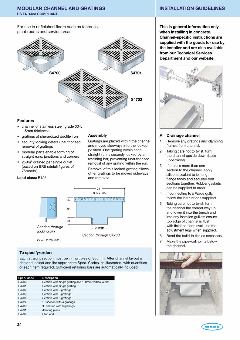
INSTALLATION GUIDELINES
A. Drainage channel1. Remove any gratings and clamping
frames from channel.
2. Taking care not to twist, turn the channel upside down (base uppermost).
3. If there is more than one section to the channel, apply silicone sealant to jointing flange faces and securely bolt sections together. Rubber gaskets can be supplied to order.
4. If connecting to a Wade gully, follow the instructions supplied.
5. Taking care not to twist, turn the channel the correct way up and lower it into the trench and into any installed gullies: ensure top edge of channel is flush with finished floor level, use the adjustment legs when supplied.
6. Bend the build-in ties as necessary.
7. Make the pipework joints below the channel.
This is general information only, when installing in concrete. Channel-specific instructions are supplied with the goods for use by the installer and are also available from our Technical Services Department and our website.
For use in unfinished floors such as factories, plant rooms and service areas.
Features• channel of stainless steel, grade 304, 1.5mm thickness
• gratings of sherardized ductile iron
• security locking deters unauthorised removal of gratings
• modular parts enable forming of straight runs, junctions and corners
• 250m2 drained per single outlet (based on BRE rainfall figures of 75mm/hr)
Load class: B125
S4700
To specify/order:Each straight section must be in multiples of 305mm. After channel layout is decided, select and list appropriate Spec. Codes, as illustrated, with quantities of each item required. Sufficient retaining bars are automatically included.
Section through S4700
Section through locking pin
311
305 x 305
27
98
44
4" BSP
Spec. Code DescriptionS4700 Section with single grating and 100mm vertical outletS4701 Section with single gratingS4702 Section with 2 gratingsS4703 Section with 3 gratingsS4706 Section with 6 gratingsS4724 ‘T’ section with 4 gratingsS4733 ‘L’ section with 3 gratingsS4791 Jointing pieceS4792 Stop end
Patent 2 209 782
S4701
S4702
AssemblyGratings are placed within the channel and moved sideways into the locked position. One grating within each straight run is securely locked by a retaining bar, preventing unauthorised removal of any grating within the run.
Removal of this locked grating allows other gratings to be moved sideways and removed.
MODULAR CHANNEL AND GRATINGS BS EN 1433 COMPLIANT

2522222525252525252525
BS EN 1433 COMPLIANT
B. Drainage Channel profile SVF – for use with vinyl and other flexible sheet material
The following additional notes/ procedures apply:
1. Dress vinyl into channel and fix in accordance with flooring manufacturer’s instructions.
2. Fit clamping frames and gratings.
C. Drainage channels with perimeter angle frame
The following additional notes procedures apply:
1. When the channel is installed, lay the floor into the perimeter angle frame.
2. Once the floor is set, carefully remove the spacer bars between the angle frame and the channel using an angle grinder or similar.
Note Do not remove the spacer bars
before fitting the channel, as it would then be impossible to maintain the position of the frame relative to the channel.
3. Thoroughly clean the gap between the channel and angle frame, degrease and fill with a permanently elastic expansion joint sealant. If corrosive chemicals are likely to be present, consult sealant manufacturer on suitability.
8. lf not supplied, provide and insert spacer bars across channel at approx. 500mm centres. Spacer bars prevent channel being squeezed while backfill is being compacted and must not be removed until backfill is set.
9. Fix the channel into position by first grouting build-in ties and any adjustment legs firmly in place.
Note After positioning the channel it is recommended that a water test be undertaken to check that height is correct, that, where applicable, the fall in the channel works effectively, that there are no leakages from the channel system and that there are no signs of deformation or of damage to the channel which may have occurred during installation. At this stage it may still be possible for any necessary rectification work to take place. Please consult our Technical Services Department if this situation arises.
10. Taking care not to damage show surfaces, place heavy weights on top of the channel prior to pouring backfill to prevent any lift or movement.
11. Using concrete class C30/37 backfill around the channel ensuring that the concrete flows evenly under and around the channel such that no voids are formed.
12. Remove immediately any material which falls into the channel.
13. When concrete is set, remove spacer bars.
14. Fit gratings.
15. Clean channels and gratings with water and a suitable cleaning agent where necessary. Under no circumstances use metal scouring pads or wire wool as these will contaminate surfaces.
Note Load classes given are based on channel being set in concrete class C30/37, to a level that fully supports the grating seat. For a lower load rating, lesser amounts and class of concrete may be suitable – consult a structural engineer if advice is needed.
For additional notes on channel profile SVF and channel with perimeter angle frame, see B and C.
26
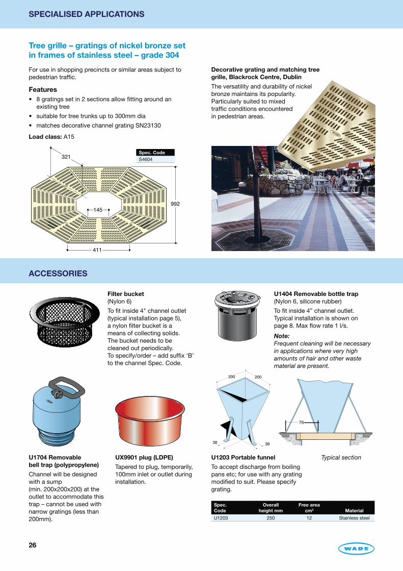
SPECIALISED APPLICATIONS
Tree grille – gratings of nickel bronze set in frames of stainless steel – grade 304
ACCESSORIES
For use in shopping precincts or similar areas subject to pedestrian traffic.
Features• 8 gratings set in 2 sections allow fitting around an
existing tree
• suitable for tree trunks up to 300mm dia
• matches decorative channel grating SN23130
Load class: A15
Filter bucket (Nylon 6)
To fit inside 4" channel outlet (typical installation page 5), a nylon filter bucket is a means of collecting solids. The bucket needs to be cleaned out periodically. To specify/order – add suffix ‘B’ to the channel Spec. Code.
U1704 Removable bell trap (polypropylene)
Channel will be designed with a sump (min. 200x200x200) at the outlet to accommodate this trap – cannot be used with narrow gratings (less than 200mm).
U1203 Portable funnel
To accept discharge from boiling pans etc; for use with any grating modified to suit. Please specify grating.
UX9901 plug (LDPE)
Tapered to plug, temporarily, 100mm inlet or outlet during installation.
Typical section
U1404 Removable bottle trap (Nylon 6, silicone rubber)
To fit inside 4” channel outlet. Typical installation is shown on page 8. Max flow rate 1 l/s.
Note: Frequent cleaning will be necessary in applications where very high amounts of hair and other waste material are present.
Decorative grating and matching tree grille, Blackrock Centre, Dublin
The versatility and durability of nickel bronze maintains its popularity. Particularly suited to mixed traffic conditions encountered in pedestrian areas.
321
145
411
992
200 200
3838
76
Spec. Code
Overall height mm
Free area cm2 Material
U1203 250 12 Stainless steel
Spec. CodeS4604
27
MATERIALS/CARE AND MAINTENANCE
Load rating class
Materials and finish of Wade gratings and channel, described below, are selected to provide lasting performance and to blend with surroundings. The products require the minimum of maintenance, but periodic inspection should be carried out to ensure absence of matter which could impede drainage. Measures set out below will sustain appearance and prolong service life.
Cast aluminium – BS EN 1706Used for gratingsAn alloy chosen for its chemical resistance and durability.
Cast iron – BS EN 1561Used for gratings and gulliesA widely used metal in the drainage industry, its resistance to corrosion permits extended use under extreme conditions. Castings are coated with a high grade lacquer paint, applied by full immersion dip, to provide internal and external surface coverage. Paint will gradually wear off and is replaceable; oxidisation (surface rusting) is a natural process which does not weaken the material. A zinc anti-corrosion coating is applied to certain castings by sherardizing.
Ductile iron – BS EN 1563 and 1564Used for gratingsA casting with the ductility of steel, yet with more than twice the tensile strength of cast iron. A zinc anti-corrosion coating is applied by sherardizing.
NeopreneUsed for gaskets and seals. Maximum continuous operating temperature of 100°C.
Nickel bronze – BS EN 1982 satin finishUsed for gratingsA cast alloy with a fine grain effect which blends well with most floor finishes. The satin finish is generally maintained by the slight abrasive action of passing traffic. In unused
Materials/care and maintenance
areas the material will gradually tarnish. To restore lustre, apply a plain nylon scouring pad (not soap-filled) in the direction of the grain.
Nylon 6Used for filter bucket and removable bottle trapChosen for its toughness and durability. Maximum continuous operating temperature of 180°C.
PolypropyleneUsed for the removable trap in stainless steel gullies. Maximum continuous operating temperature of 100°C.
Silicone rubberUsed in O-ring in removable bottle trap. Maximum continuous operating temperature of 180°C.
Stainless steel – grade 304 and 316Used for bodies, channels, gratings, funnels, access covers, filter buckets and fixingsA corrosion-resistant metal containing significant amounts of nickel and chromium; AISI grade 304 stainless steel is used as standard, which is suitable for general use in and around buildings including most coastal locations. In applications such as swimming pools or having an aggressive atmosphere, grade 316 is recommended and is available on request. An even higher grade may be required for applications in highly corrosive environments including where exposure to seawater may be anticipated.
Clean with soap and warm water rinse and wipe dry. Gratings may also be cleaned in certain dishwashers.
Under no circumstances treat with metal scouring pads, metal scrapers or wire wool as these will contaminate surfaces leaving rust spots.
This catalogue shows the load rating class for each product based on BS EN 1433 as follows:
A15 Areas which can be used only by pedestrians and pedal cyclists.
B125 Footways, pedestrian and comparable areas, private car parks and car parking decks.
C250 Kerbsides – maximum of 0.5 m into the carriage way and a maximum of 0.2m into the footway.
D400 Carriageways of roads (including pedestrian streets), hard shoulders and parking areas, for all types of road vehicles.
Channel load ratings are as tested when cast in concrete grade C30/37 up to finished floor level. Channels installed in other types of floor construction may not meet the same load class if they are not fully supported.
Where grating and channel within an assembly are different load classes the lower class is applicable to that assembly.
The selection of the appropriate class is the responsibility of the designer; where there is any doubt the stronger class should be used.
Spec. Code Page
D10/D11/D12 17
DSD 19
G 16
HC/HCE 20
HL 22
HSC/HSCE 20
NE/NEF/NEHD 14
PA 14
QB 17
QG 17
Q27DS/Q28DS 18
Q Styles 18
RE 14
RP/RPV 14
S46 26
Spec. Code Page
S47 24
S48 23
SA 12
SC 13
SE 14
SG 13
SL 22
SN 12
SS 10-11
SSD 19
SSL 22
SVF/SVFE 14
TDN/TDR 21
U 26
Spec. Code index

8158
About WadeVisit our website for online versions of our product catalogue, price list, conditions of sale, news, job opportunities, Wade CAD, Wade BIM and PDF format technical handbooks.
Wade CAD is for users who require drawings of Wade products; files are in both DXF and AutoCAD DWG format.
Wade BIM is our library of BIM 3D models available for a range of products in Revit format.
Wade International Ltd.Third Avenue • HALSTEAD
Essex • CO9 2SX • UKTelephone: +44(0)1787 475151 • Facsimile: +44(0)1787 475579
e-mail: [email protected] • web site: www.wade.eu
Other Wade literature
QUALITY BY TRADITION PERFORMANCE BY DESIGN
ServiceProduct information and technical advice are available from the Wade Technical Services Department at Halstead, Essex, from Wade Technical Consultants located throughout the UK and from selected distributors throughout the world. A computer-aided design service is available free of charge for layouts and assemblies of Wade products.
WarrantyThe Company warrants its products to be free from defects in material and workmanship for a period of 12 months from the date of delivery.The Company’s obligation under this warranty is limited, at its option, to the repair or replacement, free of charge, or refund of the net invoiced price of any part found to be defective, and which, in the Company’s opinion, has not been subject to undue wear and tear, accident, alteration, abuse or misuse. Consequential damages are expressly disclaimed.
Technical advice from Wade International Limited, whether verbal, in writing or by way of trials, is given in good faith but without warranty. The application, use and installation of the Company’s products are beyond the control of the Company, and the purchaser is solely responsible for ensuring that goods are fit for any particular purpose.In line with the Company’s policy of continual research and development, product specifications and availability are subject to change or withdrawal without prior notice.
DimensionsIn line with general practice all dimensions shown are nominal.Dimensions are generally given in mm (other units are specified).