Linear Drainage Product Guide Natural Stone · Linear Drainage Product Guide ... Why Choose...
39
Linear Drainage Product Guide www.marshalls.co.uk/watermanagement
-
Upload
hoangkhanh -
Category
Documents
-
view
223 -
download
0
Transcript of Linear Drainage Product Guide Natural Stone · Linear Drainage Product Guide ... Why Choose...

Natural StoneLinear Drainage Product Guide
www.marshalls.co.uk/watermanagement

Mini Beany, Bedford
Mini Beany, Bedford
Beany Block, Newcastle
Drexus XL, Example
Mono Beany, A259
Beany Block, Newcastle
Max-E Channel, Bedford
Drexus 100, Example
Mono Slot Drain, Doncaster
Birco 150, LondonMini Beany, Conservation, Bedford
Linear Drainage Product Guide
Linear D
rainag
e Product G
uide
Linear D
rainag
ew
ww
.marshalls.co.uk/com
mercial/w
ater-managem
ent
Linear D
rainag
ew
ww
.marshalls.co.uk/com
mercial/w
ater-managem
entLin
ear Drain
age Prod
uct Guid
e
Contents
Section 1 - Introduction
Why Choose Marshalls .................................................................4 - 5
Marshalls Linear Drainage Services .........................................6 - 7
Section 2 - Linear Drainage Overview
Product Selection ...........................................................................8 - 9
Linear Drainage Channels ......................................................10 - 11
Linear Drainage Tops................................................................12 - 13
Section 3 - Channel Drainage Product Range
Drexus Pave Drain .....................................................................15 - 18
Drexus Slot Drain .......................................................................20 - 24
Drexus 100 ...................................................................................25 - 28
Birco Lite .......................................................................................29 - 32
Birco 100 .......................................................................................33 - 36
Birco 150 .......................................................................................37 - 40
Traffic Drain .................................................................................41 - 44
Birco 200 .......................................................................................45 - 48
Max-E Channel ...........................................................................49 - 52
Drexus XL......................................................................................53 - 56
Section 4 - Combined Kerb & Drainage Product Range
Mono Beany ................................................................................59 - 62
Mini Beany ...................................................................................65 - 68
Beany Block .................................................................................69 - 72
NEW
NEW
NEW
NEW

Why Choose Marshalls?
Introduction
Why C
hoose Marshalls
4
ww
w.m
arshalls.co.uk/comm
ercial/water-m
anagement
5
ww
w.m
arshalls.co.uk/comm
ercial/water-m
anagement
Introduction
Why C
hoose MarshallsLinear Drainage Product Guide
Linear D
rainag
e
Linear D
rainag
e
Marshalls experience and expertise can ensure that the right system is selected, detailed, delivered and installed to give total peace of mind.
Marshalls pledges that all of the drainage products featured in this book comply with relevant industry standards, are manufactured to the highest standards, are fit for purpose and are designed to optimise savings in manufacture and use.
Marshalls’ purchasing policy sets out the standards and ethics by which we conduct our business and operate our management systems to manage our suppliers.
The majority of our products are manufactured in the UK; where products are sourced from outside the UK an ethical risk assessment is completed and an appropriate action plan agreed - multi-stakeholder independent social audits are part of our best practice. Marshalls is a member of both the Ethical Trading Initiative and UN Global Compact.
Marshalls accepts legal compliance as an absolute minimum standard to which we work and, where no legislation is in place, we use industry best practice. Legal compliance is monitored through our independently audited management systems. Our Board is ultimately responsible for ensuring the business operates in a socially responsible way, including compliance with relevant legislation.
Marshalls plc is the UK’s leading hard landscaping company. We have achieved this status through progressive product innovation and by demonstrating outstanding service levels to our customers. This privileged position will be sustained by continuous investment in our brand, our products, and our people.
This dedication to excellence is exemplified by Marshalls committment to developing a first class range of linear channel drainage products that fit even the most bespoke hydraulic system requirements.
OHS 69609 EMS 56194 FM 00004 IMR 72571
We’re dedicated to creating spaces that make the world a better place for everybody – one pavement, one car park, and one city centre at a time.
Our vision is built upon four pillars: values by which our every decision is guided, no matter how big or small.
Building trust.
Everyone at Marshalls acts with integrity, treating customers and their projects with care and respect. It means people trust us with their home, their business, their town. And it’s how we foster relationships for the long-term.
Being sustainable.
We use the world to source our products, so we have a responsibility to look after it. It’s something we have been committed to for over 120 years and has ensured our longevity. Whether it’s creating stronger communities, preserving environments, or contributing to the UN Global Compact, our work is always sustainable.
Demonstrating leadership.
We believe in driving the industry forward. It’s an ambition we’ve been acting on for 120 years, thanks to our size, capability, range of products and unmatched market knowledge.
Delivering excellence.
We have very high standards. Our products have to be innovative, our people have to be the best, our workmanship has to be perfect. Only then can we deliver the quality we’re renowned for, at every stage of the process.
2015
Marshalls is a member of the Ethical Trading Initiative (ETI).
Design Space
A bespoke London work space to inspire landscape design professionals. Bookable spaces for meetings, brainstorm sessions, or simply quiet space to think and create.Fully kitted to explore materials, colours and textures, BIM Models, technical data and social media platforms all on screen.
Extra events are a regular programme of seminars, notable speakers, and CPD. Open Space for big ideas, Personal Space for quiet contemplation, Inner Space for imagination.
360 Service Package
Our 360 Service Package provides comprehensive support including pre-construction appraisal, product sampling and CAD facilities. Marshalls Water Management and hydraulic engineering consultants are on hand at all stages of planning and
construction to help ensure sound hydraulic design and sustainable performance of the drainage installation. To smooth project management our construction service teams employ state of the art traffic planning software for real time tracking and priority delivery schedules. All of this is underpinned with RIBA accredited training seminars for project teams. Visit marshalls.co.uk/360 to find out how your project can benefit.
Bespoke Solutions
Detailed design features often make the difference between good and great. Marshalls is always delighted to take challenging briefs for bespoke landscape linear drainage features.
Liverpool Lime Street Station required a discreet drainage solution to follow the curvature of the architecture. Marshalls was able to develop a true radius slot drain to meet the clients requirements.
The client of the Welding Institute in Cambridge required a linear drainage solution for a multi story car park. Marshalls was able to recommend and supply Marshalls Birco Profil, a shallow steel channel designed for low construction heights whilst providing optimum drainage performance, reliable traffic safety and attractive design.
Technical Design Guide
The fully comprehensive Marshalls Linear Drainage Design Guide draws from Marshalls experience in linear drainage, and aims to help the reader to understand more about this subject in a comprehensive and easy to understand way.
The guide, walks the reader through all the Product Range, the case for linear drainage, cost comparisons, the product selection process and design principles. The guide also provides technical information, offering advice on design, installation, materials and maintenance.
Introduction
Marshalls Linear D
rainage Services
6
ww
w.m
arshalls.co.uk/comm
ercial/water-m
anagement
7
ww
w.m
arshalls.co.uk/comm
ercial/water-m
anagement
Introduction
Marshalls Linear D
rainage ServicesLinear Drainage Product Guide
Linear D
rainag
e
Linear D
rainag
e
BIM & Product innovation
Marshalls is an early adopter of Building Information Modelling (BIM) and has invested heavily in developing our people and skills to create the appropriate BIM objects and data that large commercial projects will soon demand. The company is in the process of building a BIM object library that will be unrivalled in the Landscape sector and currently collaborates with relevant industry bodies to develop the training strategies, product data and software that will drive BIM adoption across the industry.
Design Service & Project Support
Engineering Solutions
Marshall is committed to ensuring that the right system is selected, detailed, delivered and installed. The understanding that the right selection of linear drainage system is crucial to the function of any hard landscaped area therefore Marshalls Linear Drainage team will work in partnership with the specifer, engineer and contractor, to become an integrated part of the design process, helping transform and deliver ideas into hydraulic designs matched to the individual project requirements to give total peace of mind.
In-House Design Support Services
By use of our bespoke computer software the design team can plan realistic and rapid solutions to your drainage needs. The Design Team will:
• Work with the project team to ensure the client’s expectation are met
• Operate with either electronic (CAD) or hard copy drawings
• Assist in the selection of the most appropriate system
• Provide hydraulic data to support the adequacy of the selected system
• Provide schedule and / or layouts of the components as appropriate
Flexible input options enable the user to generate required rainfall events in terms of duration and return period whilst also having the capability to adjust for climate change. These features ensure that each Marshalls linear drainage design can be tailored to meet the requirements of a specific project.
The Online Design Tool will:
• Give access at all times from most web active devices• Save designs to a personal online library within your account • Give access to pre-designed templates for fast track designing• Automatically update with additional or new
product and technical data • Calculate flow rates and capacity levels required
NEW Online Hydraulic Design Software
Marshalls bespoke software (the online design tool) can enable you to plan realistic, precise and cost effective solutions to your drainage needs, all at your fingertips through a simple step-by-step process.
The software uses the modified rational method as described in the Wallingford procedure to calculate appropriate runoff rates for your project. A simple procedure is followed to ensure selection of the correct Marshalls linear drainage system from a structural, aesthetic and hydraulic perspective.
CPD Presentations and Training
Marshalls Linear Drainage Team provides free of charge comprehensive and industry leading range of CPD (Continuous Professional Development) seminars to architects, engineers and contractors.
Marshalls CPD seminars cover a whole range of water management topics and solutions from permeable paving to linear and combined kerb and drainage systems.
“Our everyday goal is simple – Support the customer’s performance and aesthetic design aspirations with a commercially driven, value added Design support service, excelling through computer aided drawings, engineered solutions and technical advice.”
Marshalls free, no-obligation Drainage Design Service encompasses the following services:
Further Technical documentation is also available;
• Conduit files• Computer Aided Design product drawings• Technical product data and specification sheets • Declaration of performances in accordance with
BS EN 1433:2002• Maintenance and cleaning regimes• Online installation guides & videos.
Available January 2016

ww
w.m
arshalls.co.uk/comm
ercial/water-m
anagement
Linear D
rainag
e Overview
Product Selection
Linear D
rainag
e Overview
Product Selectionw
ww
.marshalls.co.uk/com
mercial/w
ater-managem
ent
STEP1Hydraulic capacity - the volume of water expected to be removed, low, medium or high
STEP 2Load Classification - what loading the drainage will be subjected to, conditional on the purpose of the scheme, ranging from pedestrian and cyclist to traffic with high wheel loads
STEP 3 Aesthetics – Marshalls provides a wider choice of finish than most whatever the purpose
STEP 1 CapacitySTEP 1 Capacity
STEP 2 LoadingSTEP 2 Loading
STEP 3 Aesthetics STEP 3 Aesthetics
Decision Steps For Linear Drainage
CHANNEL DRAINAGE COMBINED KERB & DRAINAGE
Once the type of linear drainage system is determind there are three decisions to make in order to select the right product for your requirement:
Linear Drainage Product Guide
Linear D
rainag
e
Linear D
rainag
e
8 9
125Kn Test Load
Footways, pedestrian areas, car parks, car parking decks and similar areas used by light, slow-moving traffic.
High Capacity
Drains an area in excess of 1750m2 or typical run lengths over 100 lin m.
Medium Capacity
Drains an area up to 1750m2 or typical run lengths up to 100 lin m.
Low Capacity
Drains an area up to 750m2 or typical run lengths up to 30 lin m.
250Kn Test Load
Kerb-sides, general parking areas and hard shoulders that extend to a maximum of 0.5m into the trafficked area.
400Kn Test Load
Carriageways of roads (including pedestrian streets and parking areas) catering for all legal road-going vehicles.
600kN Test Load
Private traffic areas used by vehicles imposing particularly heavy wheel loads.
900Kn Test Load
Special areas of abnormally heavy wheel loads e.g. aircraft pavements.

• Available in 1000mm and 500mm lengths• Available in 4 constant invert depths of 110 (0/0), 160 (5/0), 210 (10/0), 260mm (15/0)• Base transition unit available• Radius units available• End caps, cap outlets and cover plates and outfalls• Tops – cast iron and Mini Beany tops
Traffic Drain & Mini Beany Channel
Max-E & Beany Channel
ww
w.m
arshalls.co.uk/comm
ercial/water-m
anagement
Linear D
rainag
e Overview
Linear Drainage C
hannels
Linear D
rainag
e Overview
Linear Drainage C
hannelsw
ww
.marshalls.co.uk/com
mercial/w
ater-managem
ent
• Available in 1000mm and 500mm lengths• Invert width of 100mm• Available in 5 constant invert depths of 100 (0/0), 150 (5/0), 200 (10/0), 250 (15/0) and 300mm (20/0)• 20 inbuilt fall channels with a gradient of 1%, each 1000mm long• T-Junctions, end caps, cap outlets and outfalls• Tops – cast iron and galvanised cast iron/steel grates
Birco 100 Channel
Birco 150 Channel
• Available in 1000mm and 500mm lengths• Invert width of 150mm• Available in 5 constant invert depths of 150 (0/0), 200 (5/0), 250 (10/0), 300 (15/0) and 350mm (20/0)• 20 inbuilt fall channels with a gradient of 1%, each 1000mm long• T-Junctions, end caps, cap outlets and outfalls• Tops – cast iron and galvanised cast iron/steel grates
• Available in 1000mm and 500mm lengths• Invert width 100mm• Available in 5 constant invert depths of 90 (0/0), 115 (5/0), 140 (10/0), 165 (15/0) and 190mm (20/0)• 4 transition units, each 1000mm long• T-Junctions, end caps, cap outlets and outfalls• Tops – Drexus Pave Drain, Drexus Slot Drain, cast iron grate tops
Drexus 100
• Available in 500mm lengths
• Available in 4 constant invert depths of 100 (0/0), 170 (5/0), 240 (10/0), 520mm (15/0)
• Base transition unit available
• Radius units available
• End caps, cap outlets, cover plates and outfalls
• Tops – concrete, in-laid, cast iron and beany tops
• Available in 1000mm lengths• Invert widths of 100, 150 and 300mm• Available in 6 constant invert depths of 20, 40, 50, 80, 130, 180mm• End caps and cap outlets• Tops – cast iron and galvanised cast iron/steel grates
Birco Shallow Channel
• Available in 1000mm and 500mm lengths• Invert width of 100mm• Available in 5 constant invert depths of 90 (0/0), 115 (5/0), 140 (10/0), 165 (15/0) and 190mm (20/0)• 20 inbuilt fall channels with a gradient of 0.5%, each 1000mm long• T-Junctions, end caps, cap outlets and outfalls• Tops – cast iron and galvanised cast iron/steel grates
Birco Lite Channel
Choice depends on:
Step 1- Hydraulic capacity, from low to highStep 2 - Loading application from B125 to F900
Constructed from high performance concrete or medium density polyethylene, there’s a channel solution for every scheme.
Steps 1 & 2 - Choose Your Channel
Linear Drainage Product Guide
Linear D
rainag
e
Linear D
rainag
e
10 11
• Available in 2000mm lengths
• Invert width 188 (325), 319 (425), 379 (525), 482 (675), 586mm (825)
• Available in 5 constant invert depths of 505 (325), 631 (425), 721 (525), 857 (675), 1014mm (825)
• 8 transition units each approx 478mm long
• End caps, chamber transitions and outfalls
• Tops - In-situ cast concrete
Drexus XL
Steps 1 & 2 helps you to select the right channel to suit your capacity and loading requirement.
• Available in 1000mm and 500mm lengths• Invert width of 200mm• Available in 4 constant invert depths of 205 (0/0), 230 (5/0), 255 (10/0), 280 (15/0) and 350mm (20/0)• 20 inbuilt fall channels with a gradient of 1%, each 1000mm long• T-Junctions, end caps, cap outlets and outfalls• Tops – cast iron grates
Birco 200 Channel
Drexus XL Insitu Cast Concrete
Drexus XL Insitu Cast Concrete
Drexus XL Insitu Cast Concrete
ww
w.m
arshalls.co.uk/comm
ercial/water-m
anagement
Linear D
rainag
e Overview
Linear Drainage Tops
Linear D
rainag
e Overview
Linear Drainage Tops
ww
w.m
arshalls.co.uk/comm
ercial/water-m
anagement
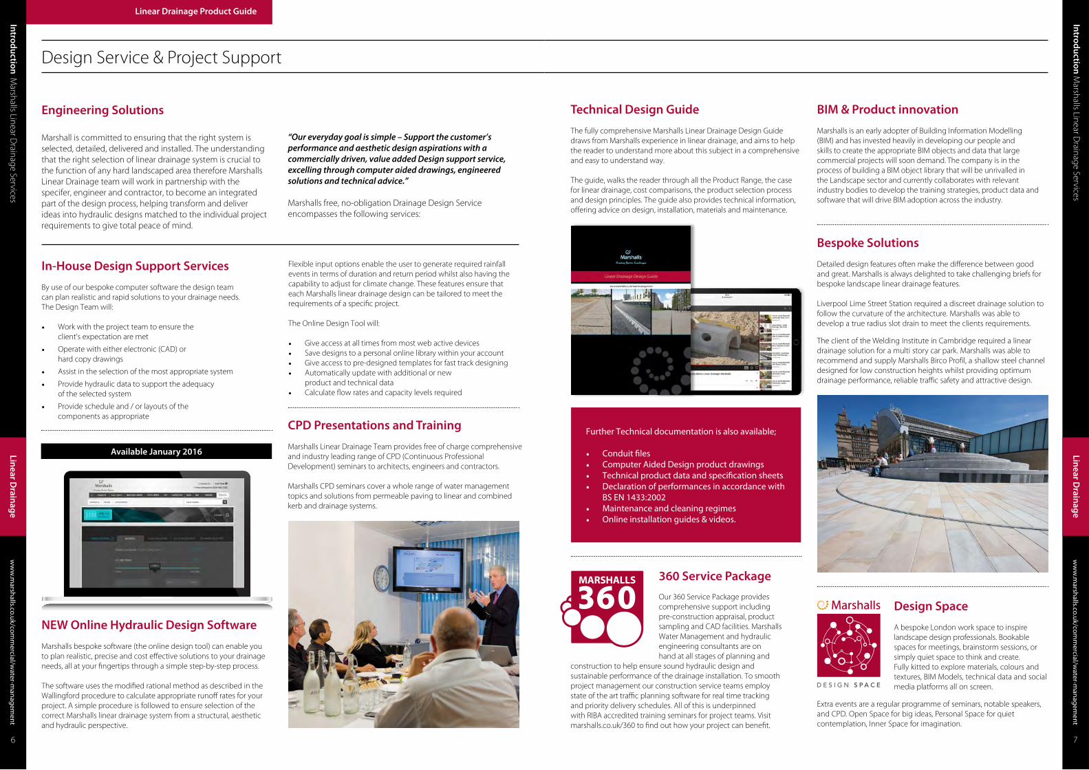
Step 3 - Choose Your Top
MEDIUM CAPACITY
Drains an area up to 1750m2*or typical run lengths up to
100 lin m
LOW CAPACITY
Drains an area up to 750m2*or typical run lengths up to
30 lin m
HIGH CAPACITY
Drains an area in excess of 1750m2* or typical run
lengths over 100 lin m
Birco 150 12mm Slotted Cast Iron
Birco 150 12mm Slotted Cast Iron
Birco 150 12mm Slotted Cast Iron
Birco 100 12mm Slotted Cast Iron
Traffic Drain
Traffic Drain
Max-E Channel Standard Grey
Drexus XL Insitu Cast Concrete
Birco 150 Cast Iron Solid Cover Birco 150 20 x 30mm Mesh Galvanised Steel
Birco 100 12mm Slotted Cast Iron
Birco 150 12mm Slotted Cast Iron
Birco 150 6mm Heelsure Cast Iron
Birco 100 13mm Diagonal Cast Iron
Birco 100 Cast Iron Solid Cover
Birco 100 20 x 30mm Mesh Galvanised Steel
Birco 100 6mm Heelsure Cast Iron
Birco 150 12mm Slotted Galvanised Cast Iron
Mono Beany Standard Grey
Birco Lite 6mm Heelsure Cast Iron
Drexus 100 6mm Heelsure Cast Iron
Birco Lite Ellipse Cast Iron
Birco Lite 12mm Slotted Cast Iron
Drexus 100 12mm Slotted Cast Iron
Drexus Slot Drain Duo Drexus Slot Drain Duo Offset
Drexus Pave Drain Horizontal Textured Silver Grey
Drexus Pave Drain Horizontal Mid Grey Granite
Drexus Pave Drain Horizontal Yorkstone
Drexus Pave Drain Horizontal Textured Buff
Drexus Pave Drain Horizontal Silver Grey Granite
Mono Beany Standard Grey
Birco 150 12mm Slotted Cast Iron
Birco Lite 30 x 15mm Mesh Galvanised Steel
Birco Lite 12mm Slotted Cast Iron
Drexus 100 12mm Slotted Cast Iron
Birco 100 30 x 12mm Galvanised Steel Mesh
Birco Lite 6mm Heelsure Cast Iron
Drexus 100 6mm Heelsure Cast Iron
Birco Lite 12mm Slotted Stainless Steel
Birco 100 12mm Slotted Cast Iron
Birco 100 30 x 30mm Mesh Galvanised Steel
Drexus Slot Drain Mono
*Drainage areas are a guide and are based on a minimum gradient of 1 in 1000 and 50mm/hr
Birco Lite 6mm Heelsure Cast Iron
Drexus 100 6mm Heelsure Cast Iron
Birco 300 20mm Slotted Cast Iron
Max-E-Channel Cast Iron
Step 3 - AestheticsMarshalls Linear Drainage Systems allow designers the broadest of choices to suit their scheme aesthetic. Drainage tops are made in a variety of materials, patterns and colours.
The chart below shows the Drainage Top styles available for different linear base classifications.
CLASS C250250kN TEST LOAD
Kerb-sides, general parking areas and hard shoulders that extend to a maximum of 0.5m into the trafficked area.
CLASS D400400kN TEST LOAD
Carriageways of roads (including pedestrian streets and parking areas) catering for all legal road-going vehicles.
CLASS E600600kN TEST LOAD
Private traffic areas used by vehicles imposing particularly heavy wheel loads.
CLASS B125125kN TEST LOAD
Footways, pedestrian areas, car parks, car parking decks and similar areas used by light, slow-moving traffic.
CLASS F900900kN TEST LOAD
Special areas of abnormally heavy wheel loads e.g. aircraft pavements.
Linear Drainage Product Guide
Linear D
rainag
e
Linear D
rainag
e
12 13
Steps 1 & 2 are very much predetermined by project specifics, however the choice of aesthetics, step 3, can be made with far more freedom.
Mini Beany Conservation Silver Grey
Mini Beany Standard Grey
Max-E Channel Conservation Silver Grey
Birco 300 20mm Slotted Cast Iron
Birco 200 18mm Slotted Cast Iron
Max-E Channel Reinforced Standard Grey
Beany Block Conservation Silver Grey
Beany Block Standard Grey
Birco 150 12mm Slotted Cast Iron
Birco 150 6mm Heelsure Cast Iron
Birco 200 18mm Slotted Cast Iron
Birco 150 12mm Slotted Galvanised Cast Iron
Birco 150 Cast Iron Solid Cover
Birco 150 20 x 30mm Mesh Galvanised Steel
Mini Beany Conservation Silver Grey
Mini Beany Standard Grey
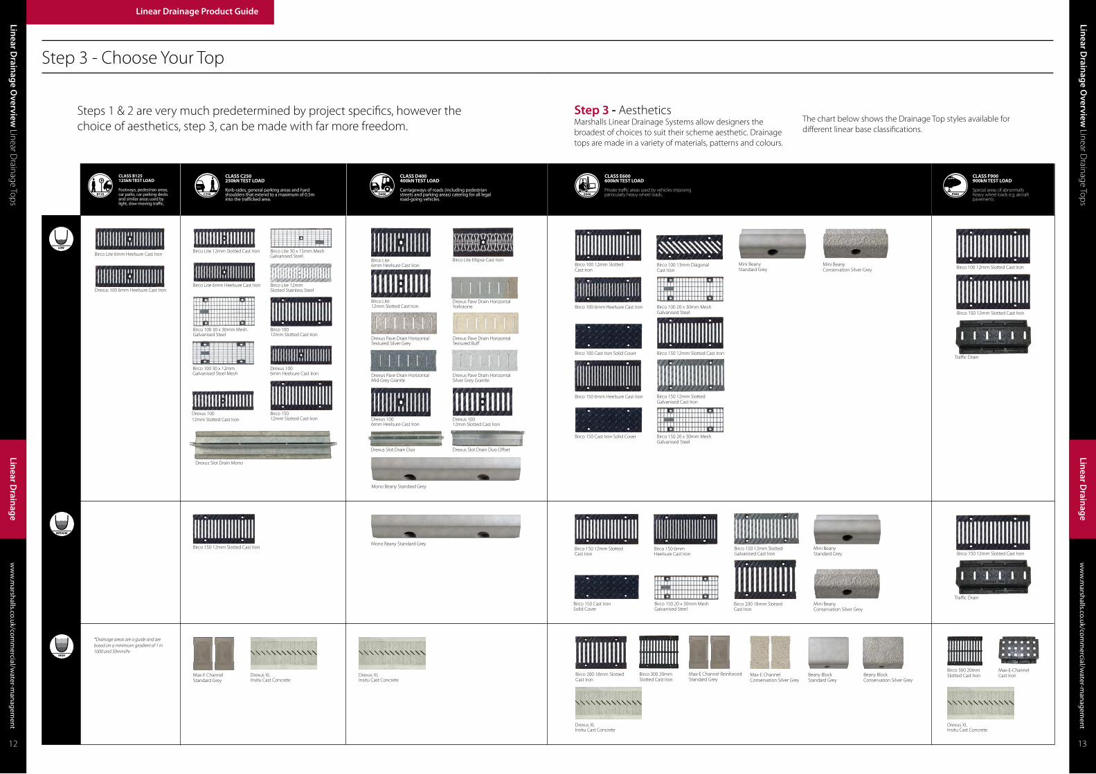
Drexus Pave Drain Paving Drainage System
Channel Drainage Product Range
Drexus Pave Drain, Example
Marshalls NEW Drexus Pave Drain offers a unique aesthetic for linear drainage. Through our concrete expertise and heritage in natural stone we have developed a drainage solution to complement our most popular paving products including premium concrete and natural stone. Drexus Pave Drain is available in a variety of finishes, suitable for any public realm development.
* Not suitable for public road carriageways or motorways
Linear C
han
nel
15
ww
w.m
arshalls.co.uk/comm
ercial/water-m
anagement
Water M
anag
ement
Linear D
rainag
e Product G
uide C
hannel Drainage Product Range
ww
w.m
arshalls.co.uk/comm
ercial/water-m
anagement
ww
w.m
arshalls.co.uk/comm
ercial/water-m
anagement
Ch
ann
el Drain
age Prod
uct Ran
ge D
rexus Pave Drain
Linear Drainage Product Guide
Linear D
rainag
e
Linear D
rainag
e
14 15
Silv
er G
rey
Gra
nit
e
Text
ured
Silv
er G
rey
Text
ured
Buff
York
ston
e, S
cout
moo
r
Mid
Gre
y G
ran
ite
D400
Q10 170

AB
EE
F
D
C
F
Linear C
han
nel
17
ww
w.m
arshalls.co.uk/comm
ercial/water-m
anagement
Water M
anag
ement
Ch
ann
el Drain
age Prod
uct Ran
ge D
rexus Pave Drain
ww
w.m
arshalls.co.uk/comm
ercial/water-m
anagement
ww
w.m
arshalls.co.uk/comm
ercial/water-m
anagement
Ch
ann
el Drain
age Prod
uct Ran
ge D
rexus Pave Drain
Linear Drainage Product Guide
Linear D
rainag
e
Linear D
rainag
e
Drexus Pave Drain
16 17
End Cap/Cap OutletsUnit Weight (kg)
Item Code
End Cap 0/0 1 DR543210End Cap 5/0 1.2 DR543220
End Cap 10/0 1.4 DR543230
End Cap 15/0 1.6 DR543240
End Cap 20/0 1.8 DR543250
Cap Outlet 0/0 1 DR543505Cap Outlet 5/0 1.2 DR543515
Cap Outlet 10/0 1.4 DR543525
Cap Outlet 15/0 1.6 DR543535
Cap Outlet 20/0 1.8 DR543545
Outfall & Access CoversUnit Weight (kg)
Item Code
Side Outfall 137 DR543020
End Outfall 101 DR543025Pave Drain Acess Cover (Low) 10 DR544770Pave Drain Acess Cover (Nat Stone) 12 DR5447750
Top LoadingLength (mm)
Width (mm)
Depth (mm)
Unit Weight (kg)
Horizontal Slot
Textured Silver Grey D400 500 160 80 15 DR544810Textured Buff D400 500 160 80 15 DR544820
Granite Silver Grey D400 500 160 105 17 DR544840
Granite Mid Grey D400 500 160 105 17 DR544850
Yorkstone Scoutmoor D400 500 160 105 17 DR544860
A Tops
Channel Transitions
End Cap/Cap Outlets
Outfall & Access Covers
Constant DepthChannels
Length (mm)
Width (mm)
InvertWidth (mm)
Depth (mm)
Invert Depth (mm)
Unit Weight (kg)
Item Code
Channel 0/0 1000 160 100 170 90 37 DR541015Channel 5/0 1000 160 100 195 115 45 DR541025Channel 10/0 1000 160 100 220 140 53 DR541035Channel 15/0 1000 160 100 245 165 61 DR541045
Channel 20/0 1000 160 100 270 190 69 DR541055
Channel 0/0 500 160 100 170 90 18.5 DR541515
Channel 5/0 500 160 100 195 115 22.5 DR541525
Channel 10/0 500 160 100 220 140 26.5 DR541535
Channel 15/0 500 160 100 245 165 30.5 DR541545
Channel 20/0 500 160 100 270 190 34.5 DR541555
Constant Depth ChannelsB
E
F
Drexus Pave Drain Channels are available with transitions. Transition Channels increase drainage discharge capacity by improving flow rates and thereby increasing the overall discharge capacity of the system. Transition channels are 1000mm long.
T Juntion Channels
T Junction Channels
Unit Weight (kg)
Item Code
T- Channel 0/0 19 DR543750
T-Channel 10/0 27 DR543760
T-Channel 20/0 35 DR543770
D
C
Drexus Pave Drain with reference numbers indicated in bold black are available ex-stock.Drexus Pave Drain with reference numbers indicated in light are manufactured to order.Contact our sales office to discuss your requrements.
ChannelTransitions
Length (mm)
Width (mm)
InvertWidth (mm)
Depth (mm)
Invert Depth (mm)
Unit Weight (kg)
Item Code
0/0 - 5/0 1000 160 100 179 104/129 39 DR5421105/0 - 10/0 1000 160 100 204 129/154 43 DR54212010/0 - 15/0 1000 160 100 229 154/179 46 DR542130
15/0 - 20/0 1000 160 100 254 179/204 50 DR542140

Pave Drain Case Study - Thistle Street, Edinburgh
BackgroundThistle Street is located at the heart of Scotland’s capital city in Edinburgh’s New Town. Built in stages between 1767 and 1850, retaining much of the original neo classical and Georgian period architecture, the New Town is considered to be a masterpiece of city planning. Together with the Old Town, it was designated a UNESCO World Heritage Site in 1995.
ChallengeWith pedestrian safety and comfort in mind, Edinburgh City Council engineers were seeking to improve drainage around the walkways in this essentially flat area, minimising the issues of ponding and standing water, creating effective channels and falls yet retaining the character of the city streets.
SolutionMarshalls Pave Drain providing the perfect solution, offering a unique aesthetic for linear drainage. Utilising expertise in both concrete and natural stone, Pave Drain provides an effective combined paving and drainage solution which perfectly complements natural stone paving products, including the Scoutmoor Yorkstone installed on Thistle Street.
Available in a variety of designs and finishes, suitable for any public realm development, the Pave Drain concept combines a natural stone upper section complete with drainage slots with a concrete channel block which sits below the upper section, allowing surface water to drain away below the surface of the walkway.
Pave Drain achieves a loading classification of D400, making it suitable for areas subject to vehicular overrun as well as pedestrian traffic, helping to create better and appropriate landscapes for some of Britain’s most iconic sites. BenefitDovetailing perfectly with existing hard landscaping products along Thistle Street, Marshalls Pave Drain is now playing an important role in maintaining safe and well-drained pedestrian walkways serving the shops and restaurants in this busy and popular area of Edinburgh.
ww
w.m
arshalls.co.uk/comm
ercial/water-m
anagement
Ch
ann
el Drain
age Prod
uct Ran
ge Case Study
Ch
ann
el Drain
age Prod
uct Ran
ge D
rexus Pave Drain
ww
w.m
arshalls.co.uk/comm
ercial/water-m
anagement
Linear Drainage Product Guide
Linear D
rainag
e
Linear D
rainag
e
Drexus Pave Drain Installation Guide
18 19
In accordance with the Health and Safety at Work etc Act 1974, the Manual Handling Operation Regulations 1992 (as amended 2004) and the Construction (Design and Management) Regulations 2015, risk assessments should be carried out to protect workers from risks associated with musculoskeletal disorders and work related upper limb disorders.
This may require the use of lifting aids to assist installation.
1. Excavation
a. Sufficient material should be excavated to accommodate the drainage channel, concrete bedding and haunching.
b. Any ‘soft spots’ or poorly compacted formation should be made good.
2. Setting Out
a. The top of the Drexus Pave Drain should be 5mm below the finished pavement surface.
b. It may be advantageous to use setting out pins and string lines to achieve the desired level for the channels.
3. Outfalls
a. Drexus Pave Drain outfalls should be installed first.
b. Sufficient material should be excavated to accommodate the trapped Drexus Pave Drain outfall units
c. 150mm of C25/30 mix (BS 8500-1&2) concrete is placed in the bottom of the excavation
d. The bottom section of the two part outfall is lowered into position
e. Sufficient M-Flex sealant is gunned onto the top horizontal surface of the bottom section of the two part Drexus Pave Drain outfall so as to provide a seal between the top and bottom sections
f. The bedding concrete should be laid and brought up level with underside of the pavement bedding course.
g. The Access Cover & Frame Units should be set directly onto a 10mm bed of mortar with mortar Class12 to BS EN 998-2:2003 along each side of the outfall unit
4. Channel Installation
a. Bedding concrete (C25/30 to BS 8500-1&2) of the appropriate thickness and depth shall be laid
b. Channels shall be laid onto the freshly mixed bedding concrete, starting at the outfall, i.e. working uphill, channel ends should about as tightly as possible.
c. Alternatively, the channels may be bedded on to a layer of 10 to 40mm cement mortar (M12 mortar to BS EN 998-2) on a previously prepared concrete foundation.
d. Where cutting is necessary, channels shall be cut so that no single Unit is less than 350mm in length.
e. All cutting and trimming of the Units shall be carried out with a concrete saw or disc cutter.
5. Channel Joint Sealant
a. Jointing of channels shall occur prior to the fixing of the top units. A bead of M Flex sealant should be gunned in to the groove formed when adjacent channels abut.
b. Surplus sealant shall be removed from the inner surface of the Units as work proceeds.
6. Top Block Installation
a. The string line should be set to the level of the top corner of Units.
b. Again, starting at the Outfall, the Units should be set directly onto a 10mm bed of mortar to mortar class 12 BS EN 998-2:2003.
c. The Top Blocks should be tamped into position close to previously laid Units and the alignment checked.
d. The levels should be checked using the string line and a spirit level.
e. In addition, the general alignment should be checked from all directions as each Block is laid. Any Unit deviating by more than 3mm in 3m from line and level shall be made good by lifting and relaying.
f. The joints between adjacent top units are dry and units should be laid hand tight to achieve either a 6mm or 12mm opening as detailed on drawing.
g. Where cutting is necessary, one or two Units shall be cut so that no single Unit is less than 200mm in length. All cutting and trimming of the Units shall be carried out with a concrete saw or disc cutter.
h. The Drexus Pave Drain top units should be protected during the construction phase to prevent debris entering the slots.
7. End Caps
a. Where the Drexus Pave Drain run does not terminate at an outfall, the base unit shall be sealed using the correct sized Drexus Pave Drain End Cap.
b. The End Cap shall be securely placed against the vertical end of the base unit and haunched with fresh concrete (C25/30 mix to BS 8500-1&2).
Client: City of Edinburgh Council
Contractor:Premier 1 (Land Services)
Engineer:City of Edinburgh Council Engineers Marshalls products used:• Yorkstone Pave Drain

Slot Drain, Example
Mono Slot Drain Duo Slot Drain
C250 D400
For the Athletes’ Village - one of the most significant new urban developments in the UK – Marshalls supplied Slot Drain Channel system to complement the range of high quality natural stone paving products also supplied by the company for this prestigious site. Slot Drain is a highly effective yet beautifully discreet solution for surface water removal on premium landscapes, with drainage channels hidden beneath the slimline galvanised steel slots, creating a virtually invisible method of removing runoff water for high end schemes.
BenefitsAs the UK’s leading supplier of hard landscaping materials, Marshalls was able to demonstrate the ability to supply the quantity and quality of products required for a project of this size. The company also operates under the triple bottom line of economic, social and environmental sustainability, placing this ethos at the very heart of the business. Marshalls is proud to be a part of creating better landscapes for future generations to live, work, rest and play in East London.
ww
w.m
arshalls.co.uk/comm
ercial/water-m
anagement
Ch
ann
el Drain
age Prod
uct Ran
ge D
rexus Slot Drain
Ch
ann
el Drain
age Prod
uct Ran
ge Case Study
ww
w.m
arshalls.co.uk/comm
ercial/water-m
anagement
Linear Drainage Product Guide
Linear D
rainag
e
Linear D
rainag
e
Slot Drain Duo Case Study - Olympic Park, London
BackgroundDubbed the construction project of the century, building the Olympic Park created not only a world class venue for the Games, but in the legacy phase a whole new London district. Marshalls is proud to have supplied a wide range of materials to the project and played a role in ensuring the project was completed on time to deliver one of the most successful Games of the modern age.
ChallengeThe ODA’s Procurement Policy demanded that sustainability credentials as well as good value and high quality were paramount for any company wishing to become a supplier to the Games. As well as guaranteeing high quality solutions, suppliers were required to deliver large quantities of materials within tight time periods, meeting complex security requirements.
SolutionThe Marshalls offer for the Olympic Park included full schedules for the quantities of different products required for each phase of the scheme, full design service for the slot drainage system, carbon footprint for all materials used and full sustainability qualification documentation. In addition, Marshalls provided a dedicated on site support team for the construction period and logistical support complying with the site Delivery Management System (DMS) booking in and security system.
The Olympic Park Roads & Bridges contract covered the road infrastructure project for the main Olympic Park. To gain a specification for the linear drainage systems and kerb units, Marshalls worked closely with the designers from a very early stage. Marshalls Beany Block, the original combined kerb and drainage system, was selected for this section of the project. For the North and South Security Plazas and the high profile Aquatics Centre designed by architect Zaha Hadid, Marshalls supplied high quality Birco linear drainage systems.
Marshalls NEW Drexus Slot Drain is a highly effective yet beautifully discreet solution for surface water removal on premium landscapes. Marshalls New Drexus 100 channel is hidden beneath a slimline galvanised steel slot which features a mono or duo linear aperture.
Perfect for complementing block or flag installations and particularly suited to Natural Stone landscapes, Drexus Slot Drain is suitable for an array of applications and public realm developments.
20 21
Drexus Slot Drain Slot Drainage System
Client: ODA
Designer:Vogt & Applied Landscape Design
Contractor:Lend Lease
Engineer:Arup
Marshalls products used:• Beany Block• Birco • Slot Drain
Q10 170

AB
EE
C
D
F
F
ww
w.m
arshalls.co.uk/comm
ercial/water-m
anagement
Ch
ann
el Drain
age Prod
uct Ran
ge D
rexus Slot Drain
Ch
ann
el Drain
age Prod
uct Ran
ge D
rexus Slot Drain
ww
w.m
arshalls.co.uk/comm
ercial/water-m
anagement
Linear Drainage Product Guide
Linear D
rainag
e
Linear D
rainag
e
Drexus Slot Drain
22 23
Top UnitsLength (mm)
Length (mm)
Width (mm)
Depth (mm)
Unit Weight (kg)
Item Code
Drexus 100 Duo Slot D400 1000 116 105 8.5 DR544510Drexus 100 Offset Duo D400 1000 140 105 11.4 DR544530Drexus 100 Mono Slot C250 1000 116 110 6 DR544520Drexus 100 Duo Slot D400 500 116 105 4.25 DR544610Drexus 100 Offset Duo D400 500 140 105 5.7 DR544630Drexus 100 Mono Slot C250 500 116 110 3 DR544620
Constant DepthChannels
Length (mm)
Width (mm)
InvertWidth (mm)
Depth (mm)
Invert Depth (mm)
Unit Weight (kg)
Item Code
Channel 0/0 1000 160 100 170 90 37 DR541015Channel 5/0 1000 160 100 195 115 45 DR541025Channel 10/0 1000 160 100 220 140 53 DR541035Channel 15/0 1000 160 100 245 165 61 DR541045
Channel 20/0 1000 160 100 270 190 69 DR541055
Channel 0/0 500 160 100 170 90 18.5 DR541515
Channel 5/0 500 160 100 195 115 22.5 DR541525
Channel 10/0 500 160 100 220 140 26.5 DR541535
Channel 15/0 500 160 100 245 165 30.5 DR541545
Channel 20/0 500 160 100 270 190 34.5 DR541555
A
B
T Junction Channels
Unit Weight (kg)
Item Code
T- Channel 0/0 19 DR543750
T-Channel 10/0 27 DR543760
T-Channel 20/0 35 DR543770
Drexus Slot Drain Channels are available with transitions. Transition Channels increase drainage discharge capacity by improving flow rates and thereby increasing the overall discharge capacity of the system. Transition channels are 1000mm long.
C
Drexus Slot Drain with reference numbers indicated in bold black are available ex-stock.Drexus Slot Drain with reference numbers indicated in light are manufactured to order.Contact our sales office to discuss your requrements.
Top Units
D
ChannelTransitions
Length (mm)
Width (mm)
InvertWidth (mm)
Depth (mm)
Invert Depth (mm)
Unit Weight (kg)
Item Code
0/0 - 5/0 1000 160 100 179 104/129 39 DR5421105/0 - 10/0 1000 160 100 204 129/154 43 DR54212010/0 - 15/0 1000 160 100 229 154/179 46 DR542130
15/0 - 20/0 1000 160 100 254 179/204 50 DR542140
Channel Transitions
End Cap/Cap OutletsUnit Weight (kg)
Item Code
End Cap 0/0 1 DR543210End Cap 5/0 1.2 DR543220
End Cap 10/0 1.4 DR543230
End Cap 15/0 1.6 DR543240
End Cap 20/0 1.8 DR543250
Cap Outlet 0/0 1 DR543505Cap Outlet 5/0 1.2 DR543515
Cap Outlet 10/0 1.4 DR543525
Cap Outlet 15/0 1.6 DR543535
Cap Outlet 20/0 1.8 DR543545
E End Cap/Cap Outlets
Outfall & Access CoversUnit Weight (kg)
Item Code
Side Outfall 137 DR543020End Outfall 101 DR543025
Slot Drain Acess Cover (Low) 10 DR544640
F Outfall & Access Covers
Constant Depth Channels
T Junction Channels

Drexus 100 Grid Drainage System
Drexus 100, Example
Marshalls NEW Drexus 100 is a cost effective lighter weight linear drainage system providing loading of up to D400 when used with the range of Drexus 100 cast Iron grates. With wall thicknesses of just 30mm, and its scalloped side walls this unit is the lightest within the Marshalls channel range.
Available for both pedestrian and standard trafficking applications, making it suitable for a variety of projects including civic, commercial and rail applications.
Ch
ann
el Drain
age Prod
uct Ran
ge D
rexus Slot Drain
ww
w.m
arshalls.co.uk/comm
ercial/water-m
anagement
ww
w.m
arshalls.co.uk/comm
ercial/water-m
anagement
Ch
ann
el Drain
age Prod
uct Ran
ge D
rexus 100Linear Drainage Product Guide
Linear D
rainag
e
Linear D
rainag
e
Drexus Slot Drain Installation Guide
24 25
In accordance with the Health and Safety at Work etc Act 1974, the Manual Handling Operation Regulations 1992 (as amended 2004) and the Construction (Design and Management) Regulations 2015, risk assessments should be carried out to protect workers from risks associated with musculoskeletal disorders and work related upper limb disorders.
This may require the use of lifting aids to assist installation.
4. Channel Installation
a. Bedding concrete (C25/30 to BS 8500-1&2) of the appropriate thickness and depth shall be laid
b. Channels shall be laid onto the freshly mixed bedding concrete, starting at the outfall, i.e. working uphill, channel ends should about as tightly as possible.
c. Alternatively, the channels may be bedded on to a layer of 10 to 40mm cement mortar (M12 mortar to BS EN 998-2) on a previously prepared concrete foundation.
d. Where cutting is necessary, channels shall be cut so that no single Unit is less than 350mm in length.
e. All cutting and trimming of the Units shall be carried out with a concrete saw or disc cutter.
1. Excavation
a. Sufficient material should be excavated to accommodate the drainage channel, concrete bedding and haunching.
b. Any ‘soft spots’ or poorly compacted formation should be made good.
2. Setting Out
a. The top of the Drexus Slot Drain should be 5mm below the finished pavement surface.
b. It may be advantageous to use setting out pins and string lines to achieve the desired level for the channels.
3. Outfalls
a. Drexus Slot Drain outfalls should be installed first.
b. Sufficient material should be excavated to accommodate the trapped Drexus Slot Drain outfall units
c. 150mm of C25/30 mix (BS 8500-1&2) concrete is placed in the bottom of the excavation
d. The bottom section of the two part outfall is lowered into position
e. Sufficient M-Flex sealant is gunned onto the top horizontal surface of the bottom section of the two part Drexus Slot Drain outfall so as to provide a seal between the top and bottom sections
f. The top section of the two part Drexus Slot Drain is lowered into position
g. The bedding concrete should be laid and brought up level with underside of the pavement bedding course.
h. The Access Cover & Frame Units should be set directly onto a 10mm bed of mortar with mortar Class12 to BS EN 998-2:2003 along each side of the outfall uni.
5. Channel Joint Sealant
a. Jointing of channels shall occur prior to the fixing of the top units. A bead of M Flex sealant should be gunned in to the groove formed when adjacent channels abut.
b. Surplus sealant shall be removed from the inner surface of the Units as work proceeds.
6. Top Unit Installation
a. The string line should be set to the level of the top corner of Units.
b. Again, starting at the outfall, the units should be dry laid onto the channel, use a mortar bed for levelling purposes if required to class 12 from BS EN 998-2:2003
c. The top units should be tamped into position close to previously laid Units and the alignment checked.
d. The levels should be checked using the string line and a spirit level.
e. In addition, the general alignment should be checked from all directions as each unit is laid. Any Unit deviating by more than 3mm in 3m from line and level shall be made good by lifting and relaying.
f. The joints between adjacent top units should be sealed with Marshalls M Tape to prevent ingress of bedding material from the surrounding pavement.
g. Where cutting is necessary, one or two Units shall be cut so that no single Unit is less than 350mm in length. All cutting and trimming of the Units shall be carried out with a concrete saw or disc cutter.
h. Any cut galvanised steel shall be renovated using Defcon Z or similar approved material.
7. End Caps
a. Where the Drexus Slot Drain run does not terminate at an outfall, the base unit shall be sealed using the correct sized Slot Drain End Cap.
b. The End Cap shall be securely placed against the vertical end of the base unit and haunched with fresh concrete (C25/30 mix to BS 8500-1&2).
8. Pavement Installation
a. Where Drexus Slot Drain is being laid adjacent to flexibly laid paving the inlet apertures should be sealed against ingress of bedding or jointing material during the construction phase.
6mm Heelsure Cast Iron 12mm Slotted Cast Iron
D400
12mm Slotted Cast Iron
C250B125
6mm Heelsure Cast Iron 6mm Heelsure Cast Iron
Q10 180

Ch
ann
el Drain
age Prod
uct Ran
ge D
rexus 100w
ww
.marshalls.co.uk/com
mercial/w
ater-managem
ent
ww
w.m
arshalls.co.uk/comm
ercial/water-m
anagement
Ch
ann
el Drain
age Prod
uct Ran
ge D
rexus 100Linear Drainage Product Guide
Linear D
rainag
e
Linear D
rainag
e
Drexus 100
26 27
Constant Depth Channels
Length (mm)
Width (mm)
InvertWidth (mm)
Depth (mm)
Invert Depth (mm)
Unit Weight (kg)
Item Code
Channel 0/0 1000 160 100 170 90 38 DR540015Channel 5/0 1000 160 100 195 115 46 DR540025Channel 10/0 1000 160 100 220 140 54 DR540035Channel 15/0 1000 160 100 245 165 62 DR540045
Channel 20/0 1000 160 100 270 190 70 DR540055
Channel 0/0 500 160 100 170 90 19 DR540515
Channel 5/0 500 160 100 195 115 23 DR540525
Channel 10/0 500 160 100 220 140 27 DR540535
Channel 15/0 500 160 100 245 165 31 DR540545
Channel 20/0 500 160 100 270 190 35 DR540555
B
B
Gratings LoadingLength (mm)
Width (mm)
Unit Weight (kg)
Item Code
6mm Heelsure Cast Iron B125 500 160 3.8 DR544010
6mm Heelsure Cast Iron C250 500 160 3.8 DR544020
12mm Slotted Cast Iron C250 500 160 3.9 DR544030
6mm Heelsure Cast Iron D400 500 160 4.5 DR54404012mm Slotted Cast Iron D400 500 160 4.95 DR544050
A
A
Gratings
Constant Depth Channels
T Junction Channels
Unit Weight (kg)
Item Code
T- Channel 0/0 19 DR543700
T-Channel 10/0 27 DR543710
T-Channel 20/0 35 DR543720
C
C
T Junction Channels
Drexus 100 Channels are available with transitions. Transition Channels increase drainage discharge capacity by improving flow rates and thereby increasing the overall discharge capacity of the system. Transition channels are 1000mm long.
Drexus 100 with reference numbers indicated in bold black are available ex-stock.Drexus 100 with reference numbers indicated in light are manufactured to order.Contact our sales office to discuss your requrements.
DD
ChannelTransitions
Length (mm)
Width (mm)
InvertWidth (mm)
Depth (mm)
Invert Depth (mm)
Unit Weight (kg)
Item Code
0/0 - 5/0 1000 160 100 195 120/145 41 DR5420105/0 - 10/0 1000 160 100 220 145/170 45 DR54202010/0 - 15/0 1000 160 100 245 170/195 48 DR542030
15/0 - 20/0 1000 160 100 270 195/220 52 DR542040
Channel Transitions
End Cap/Cap OutletsUnit Weight (kg)
Item Code
End Cap 0/0 1 DR537910End Cap 5/0 1.2 DR537920
End Cap 10/0 1.4 DR537930
End Cap 15/0 1.6 DR537940
End Cap 20/0 1.8 DR537950
Cap Outlet 0/0 1 DR538410Cap Outlet 5/0 1.2 DR538420
Cap Outlet 10/0 1.4 DR538430
Cap Outlet 15/0 1.6 DR538440
Cap Outlet 20/0 1.8 DR538450
E End Cap/Cap Outlets
OutfallsUnit Weight (kg)
Item Code
Side Outfall 137 DR538510End Outfall 101 DR538520
F
F
E
E
Outfalls

Birco LiteGrid Drainage System
A general purpose low capacity linear drainage system which combines a robust concrete channel with a wide aesthetic range of cast iron, stainless steel or galvanised grates. Available for both pedestrian and standard trafficking applications, making it suitable for a variety of projects including civic, commercial and rail applications.
Birco Lite, London Bridge Station
12mm Slotted Stainless Steel
30 x 15mm Mesh Galvanised Steel
C250
6mm Heelsure Cast Iron 12mm Slotted Cast Iron Ellipse Cast Iron
D400
12mm Slotted Cast Iron
C250B125
6mm Heelsure Cast Iron 6mm Heelsure Cast Iron
Ch
ann
el Drain
age Prod
uct Ran
ge D
rexus 100w
ww
.marshalls.co.uk/com
mercial/w
ater-managem
ent
ww
w.m
arshalls.co.uk/comm
ercial/water-m
anagement
Ch
ann
el Drain
age Prod
uct Ran
ge Birco Lite
Linear Drainage Product Guide
Linear D
rainag
e
Linear D
rainag
e
Drexus 100 Installation Guide
28 29
In accordance with the Health and Safety at Work etc Act 1974, the Manual Handling Operation Regulations 1992 (as amended 2004) and the Construction (Design and Management) Regulations 2015, risk assessments should be carried out to protect workers from risks associated with musculoskeletal disorders and work related upper limb disorders.
This may require the use of lifting aids to assist installation.
1. Excavation
a. Sufficient material should be excavated to accommodate channel units, concrete bedding and haunching.
b. Any ‘soft spots’ or poorly compacted formation should be made good.
2. Setting Out
a. Setting out pins should be accurately located to the correct line and level with a string line level with the top rear corners of the channel units.
b. It may be advantageous to locate setting out pins to the rear of the units to avoid having to lift the units over the string line.
3. Outfalls
a. Drexus Outfalls should be installed first.
b. Sufficient material should be excavated to accommodate the trapped Drexus Gulley.
c. 150mm of ST4 mix (BS 8500-1&2) concrete of the appropriate mix is placed in the bottom of the excavation.
d. The bottom section of the two part Drexus Gulley is lowered into position, with the appropriate pipe adaptor placed the aperture for connection to the underground pipework.
e. A suitable section of the wall of the outfall unit shall be cut out to allow adjacent drainage channels to abut without restricting the flow of water. Cutting shall be achieved by using a concrete saw or disc cutter.
f. Sufficient M-Flex sealant is gunned onto the top horizontal surface of the bottom section of the two part Birco Gulley so as to provide a seal between the top and bottom sections.
g. The top section of the two part Birco Gulley is lowered into position
h. The bedding concrete should be laid and brought up to the appropriate level dependant on surface finish as shown in the Drexus 100 Standard Detail Sheet.
5. Channel Joint Sealant
a. Jointing of adjacent channels shall be carried prior to fixing the gratings. Marshalls’ M-Flex sealant should be gunned into the sealant groove formed when adjacent channels abut.
b. Surplus sealant shall be removed from the inner surface of the units as work proceeds.
4. Channel Installation
a. Bedding concrete (ST1 to BS 8500-1&2) of the appropriate thickness and depth shall be laid as specified in the Drexus Standard Detail Sheets.
b. The top of the Drexus Channel shall be 5mm below the final pavement surface.
c. Channel Units shall be laid onto the freshly mixed bedding concrete, starting at the outfall, i.e. working uphill
d. Alternatively, the Channel Units may be bedded on to a layer of 10 to 40mm cement mortar (M12 mortar to BS EN 998-2) on a previously prepared concrete foundation.
e. The concrete haunching shall be of a concrete grade appropriate to the Drainage Channel Loading Class as specified in the Drexus Standard Detail Sheets.
f. Haunching shall be carried out as one operation to a complete line of Channel Units, to the dimensions indicated in the Drexus Standard Detail
g. Where channels are laid on or adjacent to existing or proposed concrete slabs, transverse joints shall be formed within the Units and haunching adjacent to the slab joints.
h. Longitudinal movement joints shall also be formed between the haunching and the slabs as described in the Drexus Drain Standard Detail Sheets.
i. Where cutting the Drexus Channel Units is required, they shall be cut with a concrete saw or disc cutter, so that no single Unit is less than 350mm long. Birco gratings shall not be cut unless directed by the engineer. Any cut galvanised steel shall be renovated using Defcon Z, or similar approved.
6. Grating Installation
a. Adjacent Carriageway and/or footway construction shall not be commenced within 3 days of any jointing or haunching/surrounding concrete being placed.
b. Drexus gratings shall be securely bolted to Drexus Channel Units, before adjacent pavement construction is commenced.
c. All gratings shall be evenly spaced with bolts tightened down securely to the appropriate torque (Lite: 25Nm, 100, 150 and 200: 75 Nm, 300:100Nm).
d. On completion of the works, the drainage channel units shall be cleaned out and left free from obstruction. This shall be carried out either by removal of gratings or by high pressure water jetting (100-150 bar at 200 litres/min minimum). Unless otherwise agreed with the specifier, the slot openings shall be covered by timber boards or other method during jetting operations.
e. Outfall units shall be emptied.
f. The cleaning process should be repeated where necessary on completion of any remedial works.
7. End Caps/End Cap Outlets
a. Where the Drexus Channel run does not terminate at an outfall, the base unit shall be sealed using the Drexus Block End Cap or End Cap Outlet.
b. These are to be held in position by installing 150mm of concrete haunching.
c. Marshalls M-Flex sealant should be gunned into the sealant groove.
Q10 180
C
E E
F
BA
D
Birco Lite
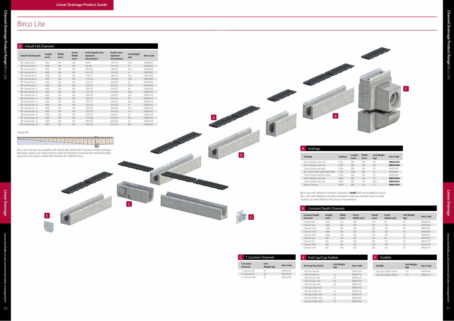
Birco Lite Channels are available with inbuilt falls. Inbuilt Fall Channels increase drainage discharge capacity by improving flow rates and thereby increasing the overall discharge capacity of the system. Inbuilt fall channels are 1000mm long.
Inbuilt Fall
Birco Lite with reference numbers indicated in bold black are available ex-stock.Birco Lite with reference numbers indicated in light are manufactured to order.Contact our sales office to discuss your requrements.
Ch
ann
el Drain
age Prod
uct Ran
ge Birco Lite
ww
w.m
arshalls.co.uk/comm
ercial/water-m
anagement
ww
w.m
arshalls.co.uk/comm
ercial/water-m
anagement
Ch
ann
el Drain
age Prod
uct Ran
ge Birco Lite
Linear Drainage Product Guide
Linear D
rainag
e
Linear D
rainag
e
30 31
E
End Cap/Cap OutletUnit Weight (kg)
Item Code
100 End Cap 0/0 1 DR045100
100 End Cap 5/0 1.2 DR045110
100 End Cap 10/0 1.4 DR045120
100 End Cap 15/0 1.6 DR045130
100 End Cap 20/0 1.8 DR045130
100 Cap Outlet 0/0 1 DR045150
100 Cap Outlet 5/0 1.2 DR045160
100 Cap Outlet 10/0 1.4 DR045170
100 Cap Outlet 15/0 1.6 DR045180
100 Cap Outlet 20/0 1.8 DR045190
End Cap/Cap Outlets F
OutfallsUnit Weight (kg)
Item Code
Lite End Outfall 100mm 101 DR050100
Lite Side Outfall 150mm 137 DR050110
Outfalls
Constant Depth Channels
Length (mm)
Width (mm)
InvertWidth (mm)
Depth (mm)
Invert Depth (mm)
Unit Weight (kg)
Item Code
Channel 0/0 1000 160 100 170 90 38 DR005015Channel 5/0 1000 160 100 195 115 46 DR005025
Channel 10/0 1000 160 100 220 140 54 DR005035
Channel 15/0 1000 160 100 245 165 62 DR005045
Channel 20/0 1000 160 100 270 190 70 DR005055Channel 0/0 500 160 100 170 90 19 DR010165Channel 5/0 500 160 100 195 115 23 DR010175
Channel 10/0 500 160 100 220 140 27 DR010185
Channel 15/0 500 160 100 245 165 31 DR010195
B Constant Depth Channels
A
Gratings LoadingLength (mm)
Width (mm)
Unit Weight (kg)
Item Code
6mm Heelsure Cast Iron B125 500 160 3.8 DR0353456mm Heelsure Cast Iron C250 500 160 3.8 DR035360
12mm Slotted Cast Iron C250 500 160 3.9 DR035350
30 x 15mm Mesh Galvanised Steel C250 1000 160 4.2 DR04046512mm Slotted Stainless Steel C250 500 160 2.7 DR041020
6mm Heelsure Cast Iron D400 500 160 4.5 DR03536612mm Slotted Cast Iron D400 500 160 4.95 DR035363Ellipse Cast Iron D400 500 160 5.7 DR041020
Gratings
D
Inbuilt Fall ChannelsLength (mm)
Width (mm)
InvertWidth (mm)
Invert Depth (mm) Upsteam/Downstream
Depth (mm) Upsteam/Downstream
Unit Weight (kg)
Item Code
IBF Channel No. 1 1000 160 100 90/95 170/175 33.5 DR020015
IBF Channel No. 2 1000 160 100 95/100 175/180 34 DR020025
IBF Channel No. 3 1000 160 100 100/105 180/185 34.5 DR020035
IBF Channel No. 4 1000 160 100 105/110 185/190 35 DR020045
IBF Channel No. 5 1000 160 100 110/115 190/195 35.5 DR020055
IBF Channel No. 6 1000 160 100 115/120 195/200 36.5 DR020065
IBF Channel No. 7 1000 160 100 120/125 200/205 37 DR020075
IBF Channel No. 8 1000 160 100 125/130 205/210 37.5 DR020085
IBF Channel No. 9 1000 160 100 130/135 210/215 38 DR020095
IBF Channel No. 10 1000 160 100 135/140 215/220 38.5 DR020105
IBF Channel No. 11 1000 100 100 140/145 220/225 39.5 DR020115
IBF Channel No. 12 1000 100 100 145/150 225/230 40 DR020125
IBF Channel No. 13 1000 100 100 150/155 230/235 40.5 DR020135
IBF Channel No. 14 1000 100 100 155/160 235/240 41 DR020145
IBF Channel No. 15 1000 100 100 160/165 240/245 41.5 DR020155
IBF Channel No. 16 1000 100 100 165/170 245/250 41.5 DR020165
IBF Channel No. 17 1000 100 100 170/175 250/255 43 DR020175
IBF Channel No. 18 1000 100 100 175/180 255/260 43.5 DR020185
IBF Channel No. 19 1000 100 100 180/185 260/265 44 DR020195
IBF Channel No. 20 1000 100 100 185/190 265/270 44.5 DR020205
Inbuilt Fall Channels
T Junction Channels
Unit Weight (kg)
Item Code
T- Channel 0/0 19 DR010210
T- Channel 5/0 23 DR010220
T- Channel 10/0 27 DR010230
C T Junction Channels

Birco Lite Installation Guide
A multi-purpose low capacity linear drainage system, combining a robust concrete channel with a wide aesthetic choice of cast iron, stainless steel or galvanised grates. A variety of loadings make Birco 100 suitable for light to heavy trafficking so suitable for a variety of projects including civic, commercial, rail and industrial applications.
Birco 100, Manchester
In accordance with the Health and Safety at Work etc Act 1974, the Manual Handling Operation Regulations 1992 (as amended 2004) and the Construction (Design and Management) Regulations 2015, risk assessments should be carried out to protect workers from risks associated with musculoskeletal disorders and work related upper limb disorders.
This may require the use of lifting aids to assist installation.
Birco 100Grid Drainage System
30 x 12mm Mesh Galvanised Steel
30 x 30mm Mesh Galvanised Steel
12mm Slotted Cast Iron
6mm HeelsureCast Iron
C250 E600
13mm Diagonal Cast Iron
12mm SlottedCast Iron
E600
20 x 30mm Mesh Galvanised Steel
Cast IronSolid Cover
12mm Slotted Cast Iron
F900
1. Excavation
a. Sufficient material should be excavated to accommodate channel units, concrete bedding and haunching.
b. Any ‘soft spots’ or poorly compacted formation should be made good.
2. Setting Out
a. Setting out pins should be accurately located to the correct line and level with a string line level with the top rear corners of the channel units.
b. It may be advantageous to locate setting out pins to the rear of the units to avoid having to lift the units over the string line.
3. Outfalls
a. Birco Outfalls should be installed first.
b. Sufficient material should be excavated to accommodate the trapped Birco Gulley.
c. 150mm of ST4 mix (BS 8500-1&2) concrete of the appropriate mix is placed in the bottom of the excavation.
d. The bottom section of the two part Birco Gulley is lowered into position, with the appropriate pipe adaptor placed the aperture for connection to the underground pipework.
e. A suitable section of the wall of the outfall unit shall be cut out to allow adjacent drainage channels to abut without restricting the flow of water. Cutting shall be achieved by using a concrete saw or disc cutter.
f. Sufficient M-Flex sealant is gunned onto the top horizontal surface of the bottom section of the two part Birco Gulley so as to provide a seal between the top and bottom sections.
g. The top section of the two part Birco Gulley is lowered into position
h. The bedding concrete should be laid and brought up to the appropriate level dependant on surface finish as shown in the Birco Standard Detail Sheet.
5. Channel Joint Sealant
a. Jointing of adjacent channels shall be carried prior to fixing the gratings. Marshalls’ M-Flex sealant should be gunned into the sealant groove formed when adjacent channels abut.
b. Surplus sealant shall be removed from the inner surface of the units as work proceeds.
4. Channel Installation
a. Bedding concrete (ST1 to BS 8500-1&2) of the appropriate thickness and depth shall be laid as specified in the Birco Standard Detail Sheets.
b. The top of the Birco Channel shall be 5mm below the final pavement surface.
c. Channel Units shall be laid onto the freshly mixed bedding concrete, starting at the outfall, i.e. working uphill
d. Alternatively, the Channel Units may be bedded on to a layer of 10 to 40mm cement mortar (M12 mortar to BS EN 998-2) on a previously prepared concrete foundation.
e. The concrete haunching shall be of a concrete grade appropriate to the Drainage Channel Loading Class as specified in the Birco Standard Detail Sheets.
f. Haunching shall be carried out as one operation to a complete line of Channel Units, to the dimensions indicated in the Birco Standard Detail
g. Where channels are laid on or adjacent to existing or proposed concrete slabs, transverse joints shall be formed within the Units and haunching adjacent to the slab joints.
h. Longitudinal movement joints shall also be formed between the haunching and the slabs as described in the Birco Drain Standard Detail Sheets.
i. Where cutting the Birco Channel Units is required, they shall be cut with a concrete saw or disc cutter, so that no single Unit is less than 350mm long. Birco gratings shall not be cut unless directed by the engineer. Any cut galvanised steel shall be renovated using Defcon Z, or similar approved.
6. Grating Installation
a. Adjacent Carriageway and/or footway construction shall not be commenced within 3 days of any jointing or haunching/surrounding concrete being placed.
b. Birco gratings shall be securely bolted to Birco Channel Units, before adjacent pavement construction is commenced.
c. All gratings shall be evenly spaced with bolts tightened down securely to the appropriate torque (Lite: 25Nm, 100, 150 and 200: 75 Nm, 300:100Nm).
d. On completion of the works, the drainage channel units shall be cleaned out and left free from obstruction. This shall be carried out either by removal of gratings or by high pressure water jetting (100-150 bar at 200 litres/min minimum). Unless otherwise agreed with the specifier, the slot openings shall be covered by timber boards or other method during jetting operations.
e. Outfall units shall be emptied.
f. The cleaning process should be repeated where necessary on completion of any remedial works.
7. End Caps/End Cap Outlets
a. Where the Birco Channel run does not terminate at an outfall, the base unit shall be sealed using the Birco End Cap or End Cap Outlet.
b. These are to be held in position by installing 150mm of concrete haunching.
c. Marshalls M-Flex sealant should be gunned into the sealant groove.
Scan the QR Code to watch the installtion video
Ch
ann
el Drain
age Prod
uct Ran
ge Birco Lite
ww
w.m
arshalls.co.uk/comm
ercial/water-m
anagement
ww
w.m
arshalls.co.uk/comm
ercial/water-m
anagement
Ch
ann
el Drain
age Prod
uct Ran
ge Birco 100
Linear Drainage Product Guide
Linear D
rainag
e
Linear D
rainag
e
32 33
Q10 180

E
E
C
A
D
F
B
B
Birco 100
D
E
A
Birco 100 Channels are available with inbuilt falls. Inbuilt Fall Channels increase drainage discharge capacity by improving flow rates and thereby increasing the overall discharge capacity of the system. Inbuilt fall channels are 1000mm long.
Inbuilt Fall
Inbuilt Fall ChannelsLength (mm)
Width (mm)
InvertWidth (mm)
Depth (mm) Upsteam/Downstream
Invert Depth (mm) Upsteam/Downstream
Unit Weight (kg)
Item Code
IBF Channel No. 1 1000 200 100 180/190 100/110 57 DR020010
IBF Channel No. 2 1000 200 100 190/200 110/120 57.5 DR020020
IBF Channel No. 3 1000 200 100 200/210 120/130 61 DR020030
IBF Channel No. 4 1000 200 100 210/220 130/140 62.5 DR020040
IBF Channel No. 5 1000 200 100 220/230 140/150 65 DR020050
IBF Channel No. 6 1000 200 100 230/240 150/160 67 DR020060
IBF Channel No. 7 1000 200 100 240/250 160/170 69 DR020070
IBF Channel No. 8 1000 200 100 250/260 170/180 71 DR020080
IBF Channel No. 9 1000 200 100 260/270 180/190 73 DR020090
IBF Channel No. 10 1000 200 100 270/280 190/200 77 DR020100
IBF Channel No. 11 1000 200 100 280/290 210/220 77 DR020110
IBF Channel No. 12 1000 200 100 290/300 220/230 81.5 DR020120
IBF Channel No. 13 1000 200 100 300/310 230/240 81 DR020130
IBF Channel No. 14 1000 200 100 310/320 250/260 86.5 DR020140
IBF Channel No. 15 1000 200 100 320/330 270/280 85 DR020150
IBF Channel No. 16 1000 200 100 330/340 280/340 91 DR020160
IBF Channel No. 17 1000 200 100 340/350 340/350 93.5 DR020170
IBF Channel No. 18 1000 200 100 360/370 360/370 96 DR020180
IBF Channel No. 19 1000 200 100 350/360 350/360 98.5 DR020190
IBF Channel No. 20 1000 200 100 370/380 370/380 101 DR020200
Constant Depth Channels
Length (mm)
Width (mm)InvertWidth (mm)
Depth (mm)
InvertDepth (mm)
Unit Weight (kg) Item Code
Channel 0/0 1000 200 100 180 100 54 DR080105Channel 5/0 1000 200 100 230 150 66 DR080115
Channel 10/0 1000 200 100 280 200 78 DR080125
Channel 15/0 1000 200 100 330 250 90 DR080135
Channel 20/0 1000 200 100 380 300 102 DR080145Channel 0/0 500 200 100 180 100 27 DR090150Channel 5/0 500 200 100 230 150 33 DR090160
Channel 10/0 500 200 100 280 200 38 DR090170
Channel 15/0 500 200 100 330 250 43 DR090180
Channel 20/0 500 200 100 380 300 51 DR090190
Shallow 80 1000 200 100 80 20 DR420450
Shallow 100 1000 200 100 100 40 DR420460
Shallow 150 1000 200 100 150 80 DR420480
Shallow 200 1000 200 100 200 130 DR420490
Gratings LoadingLength (mm)
Width (mm)
Unit Weight (kg)
Item Code
30 x 12mm Mesh Galvanised Steel C250 500 200 3.31 DR11527530 x 30mm Mesh Galvanised Steel C250 500 200 2.67 DR115260
12mm Slotted Cast Iron C250 500 200 5.0 DR115120
6mm Heelsure Cast Iron E600 500 200 7.2 DR11513512mm Slotted Cast Iron E600 500 200 6.2 DR11512513mm Diagonal Cast Iron E600 500 200 12.4 DR115020
20 x 30mm Mesh Galvanised Steel E600 500 200 4.86 DR115285
Cast Iron Solid Cover E600 500 200 7.46 DR115250
12mm Slotted Cast Iron F900 500 200 7.4 DR115130
End Cap/Cap Outlets Unit Weight (kg) Item Code
100 End Cap 0/0 1 DR045150100 End Cap 5/0 1.2 DR045155
100 End Cap 10/0 1.4 DR045160
100 End Cap 15/0 1.6 DR045165
100 End Cap 20/0 1.8 DR045170
Cap Outlet 0/0 1 DR045175
Cap Outlet 5/0 1.2 DR045180
Cap Outlet 10/0 1.4 DR045185
Cap Outlet 15/0 1.6 DR045190
Cap Outlet 20/0 1.8 DR045195
Shallow End Cap 80-100 0.02 DR425150
Shallow End Cap 150-200 0.03 DR425160
Ch
ann
el Drain
age Prod
uct Ran
ge Birco 100
ww
w.m
arshalls.co.uk/comm
ercial/water-m
anagement
Linear Drainage Product Guide
Linear D
rainag
e
ww
w.m
arshalls.co.uk/comm
ercial/water-m
anagement
Ch
ann
el Drain
age Prod
uct Ran
ge Birco 100
Linear D
rainag
e
34 35
Constant Depth Channels
Inbuilt Fall Channels
Gratings
End Cap/Cap Outlets
T Junction Channels Unit Weight (kg) Item Code
T- Channel 0/0 27 DR010210
T- Channel 5/0 33 DR010220
T- Channel 10/0 39 DR010230
C T Junction Channels
Birco 100 with reference numbers indicated in bold black are available ex-stock.Birco 100 with reference numbers indicated in light are manufactured to order.Contact our sales office to discuss your requrements.
F
Outfalls Unit Weight (kg) Item Code
100 End Outfall 100mm 105 DR130170
100 Side Outfall 150mm 142 DR130175
Outfalls

Birco 100 Installation Guide
A medium capacity linear drainage system which combines a robust concrete channel with a wide aesthetic choice of cast iron and galvanised steel grates. Birco 150 is available up to the highest loading classification making it suitable for a variety of commercial, rail and industrial applications.
Birco 150Grid Drainage System
6mm HeelsureCast Iron
12mm SlottedCast Iron
12mm SlottedCast Iron
E600C250
12mm SlottedGalvanised Cast Iron
E600
20 X 30mm Mesh Galvanised Steel
Cast IronSolid Cover
12mm SlottedCast Iron
F900
In accordance with the Health and Safety at Work etc Act 1974, the Manual Handling Operation Regulations 1992 (as amended 2004) and the Construction (Design and Management) Regulations 2015, risk assessments should be carried out to protect workers from risks associated with musculoskeletal disorders and work related upper limb disorders.
This may require the use of lifting aids to assist installation.
1. Excavation
a. Sufficient material should be excavated to accommodate channel units, concrete bedding and haunching.
b. Any ‘soft spots’ or poorly compacted formation should be made good.
2. Setting Out
a. Setting out pins should be accurately located to the correct line and level with a string line level with the top rear corners of the channel units.
b. It may be advantageous to locate setting out pins to the rear of the units to avoid having to lift the units over the string line.
3. Outfalls
a. Birco Outfalls should be installed first.
b. Sufficient material should be excavated to accommodate the trapped Birco Gulley.
c. 150mm of ST4 mix (BS 8500-1&2) concrete of the appropriate mix is placed in the bottom of the excavation.
d. The bottom section of the two part Birco Gulley is lowered into position, with the appropriate pipe adaptor placed the aperture for connection to the underground pipework.
e. A suitable section of the wall of the outfall unit shall be cut out to allow adjacent drainage channels to abut without restricting the flow of water. Cutting shall be achieved by using a concrete saw or disc cutter.
f. Sufficient M-Flex sealant is gunned onto the top horizontal surface of the bottom section of the two part Birco Gulley so as to provide a seal between the top and bottom sections.
g. The top section of the two part Birco Gulley is lowered into position
h. The bedding concrete should be laid and brought up to the appropriate level dependant on surface finish as shown in the Birco Standard Detail Sheet.
5. Channel Joint Sealant
a. Jointing of adjacent channels shall be carried prior to fixing the gratings. Marshalls’ M-Flex sealant should be gunned into the sealant groove formed when adjacent channels abut.
b. Surplus sealant shall be removed from the inner surface of the units as work proceeds.
4. Channel Installation
a. Bedding concrete (ST1 to BS 8500-1&2) of the appropriate thickness and depth shall be laid as specified in the Birco Standard Detail Sheets.
b. The top of the Birco Channel shall be 5mm below the final pavement surface.
c. Channel Units shall be laid onto the freshly mixed bedding concrete, starting at the outfall, i.e. working uphill
d. Alternatively, the Channel Units may be bedded on to a layer of 10 to 40mm cement mortar (M12 mortar to BS EN 998-2) on a previously prepared concrete foundation.
e. The concrete haunching shall be of a concrete grade appropriate to the Drainage Channel Loading Class as specified in the Birco Standard Detail Sheets.
f. Haunching shall be carried out as one operation to a complete line of Channel Units, to the dimensions indicated in the Birco Standard Detail
g. Where channels are laid on or adjacent to existing or proposed concrete slabs, transverse joints shall be formed within the Units and haunching adjacent to the slab joints.
h. Longitudinal movement joints shall also be formed between the haunching and the slabs as described in the Birco Drain Standard Detail Sheets.
i. Where cutting the Birco Channel Units is required, they shall be cut with a concrete saw or disc cutter, so that no single Unit is less than 350mm long. Birco gratings shall not be cut unless directed by the engineer. Any cut galvanised steel shall be renovated using Defcon Z, or similar approved.
6. Grating Installation
a. Adjacent Carriageway and/or footway construction shall not be commenced within 3 days of any jointing or haunching/surrounding concrete being placed.
b. Birco gratings shall be securely bolted to Birco Channel Units, before adjacent pavement construction is commenced.
c. All gratings shall be evenly spaced with bolts tightened down securely to the appropriate torque (Lite: 25Nm, 100, 150 and 200: 75 Nm, 300:100Nm).
d. On completion of the works, the drainage channel units shall be cleaned out and left free from obstruction. This shall be carried out either by removal of gratings or by high pressure water jetting (100-150 bar at 200 litres/min minimum). Unless otherwise agreed with the specifier, the slot openings shall be covered by timber boards or other method during jetting operations.
e. Outfall units shall be emptied.
f. The cleaning process should be repeated where necessary on completion of any remedial works.
7. End Caps/End Cap Outlets
a. Where the Birco Channel run does not terminate at an outfall, the base unit shall be sealed using the Birco End Cap or End Cap Outlet.
b. These are to be held in position by installing 150mm of concrete haunching.
c. Marshalls M-Flex sealant should be gunned into the sealant groove.
Scan the QR Code to watch the installtion video
ww
w.m
arshalls.co.uk/comm
ercial/water-m
anagement
Ch
ann
el Drain
age Prod
uct Ran
ge Birco 150
Ch
ann
el Drain
age Prod
uct Ran
ge Birco 100
ww
w.m
arshalls.co.uk/comm
ercial/water-m
anagement
Linear Drainage Product Guide
Linear D
rainag
e
Linear D
rainag
e
36 37
Birco 150, London
Q10 180

C
E
E
F
D
B
A
Birco 150
T-Junction ChannelsUnit Weight (kg)
Item Code
T-Channel 0/0 38 DR190020
T-Channel 5/0 44 DR190030
E
D
A
C
Birco 150 Channels are available with inbuilt falls. Inbuilt Fall Channels increase drainage discharge capacity by improving flow rates and thereby increasing the overall discharge capacity of the system. Inbuilt fall channels are 1000mm long.
Inbuilt Fall
Inbuilt Fall ChannelsLength (mm)
Width (mm)
InvertWidth (mm)
Depth (mm) Upsteam/Downstream
Invert Depth (mm)Upsteam/Downstream
Unit Weight (kg)
Item Code
IBF Channel No. 1 1000 250 150 150/160 230/240 76 DR180010
IBF Channel No. 2 1000 250 150 160/170 240/250 77 DR180020
IBF Channel No. 3 1000 250 150 170/180 250/260 77 DR180030
IBF Channel No. 4 1000 250 150 180/190 260/270 79 DR180040
IBF Channel No. 5 1000 250 150 190/200 270/280 80 DR180050
IBF Channel No. 6 1000 250 150 200/210 280/290 81 DR180060
IBF Channel No. 7 1000 250 150 210/220 290/300 82 DR180070
IBF Channel No. 8 1000 250 150 220/230 300/310 83 DR180080
IBF Channel No. 9 1000 250 150 230/240 310/320 84 DR180090
IBF Channel No. 10 1000 250 150 240/250 320/330 85 DR180100
IBF Channel No. 11 1000 250 150 250/260 330/340 86 DR180110
IBF Channel No. 12 1000 250 150 260/270 340/350 87 DR180120
IBF Channel No. 13 1000 250 150 270/280 350/360 88 DR180130
IBF Channel No. 14 1000 250 150 280/290 360/370 89 DR180140
IBF Channel No. 15 1000 250 150 290/300 370/380 90 DR180150
IBF Channel No. 16 1000 250 150 300/310 380/390 91 DR180160
IBF Channel No. 17 1000 250 150 310/320 390/400 92 DR180170
IBF Channel No. 18 1000 250 150 320/330 400/410 93 DR180180
IBF Channel No. 19 1000 250 150 330/340 410/420 94 DR180190
IBF Channel No. 20 1000 250 150 340/350 420/430 95 DR180200
Gratings LoadingLength (mm)
Width (mm)
Unit Weight (kg)
Item Code
12mm Slotted Cast Iron C250 500 250 9.3 DR1952006mm Heelsure Cast Iron E600 500 250 10.5 DR19524012mm Slotted Cast Iron E600 500 250 11.0 DR19521012mm Slotted Galvanised Cast Iron E600 500 250 11 DR19703020 x 30mm Mesh Galvanised Steel E600 500 250 7.36 DR197290Cast Iron Solid Cover E600 500 250 10.3 DR19523012mm Slotted Cast Iron F900 500 250 12.20 DR195220
End Cap/Cap Outlets Unit Weight (kg) Item Code
150 End Cap 0/0 1 DR197200150 End Cap 5/0 1.2 DR197210
150 End Cap 10/0 1.4 DR197220
150 End Cap 15/0 1.6 DR197230
150 Cap Outlet 0/0 2 DR200250
150 Cap Outlet 5/0 2 DR200260
150 Cap Outlet 10/0 2 DR200270
150 Cap Outlet 15/0 2 DR200280
Shallow End Cap 120-150 0.03 DR435250
Ch
ann
el Drain
age Prod
uct Ran
ge Birco 150
ww
w.m
arshalls.co.uk/comm
ercial/water-m
anagement
Linear Drainage Product Guide
Linear D
rainag
e
ww
w.m
arshalls.co.uk/comm
ercial/water-m
anagement
Ch
ann
el Drain
age Prod
uct Ran
ge Birco 150
Linear D
rainag
e
38 39
Birco 150 with reference numbers indicated in bold black are available ex-stock.Birco 150 with reference numbers indicated in light are manufactured to order.Contact our sales office to discuss your requrements.
B
Constant Depth Channels
Length (mm)
Width (mm)
InvertWidth (mm)
Depth (mm)
InvertDepth (mm)
Unit Weight (kg)
Item Code
Channel 0/0 1000 250 150 230 150 76 DR160200Channel 5/0 1000 250 150 280 200 88 DR160205Channel 10/0 1000 250 150 330 250 100 DR160210Channel 15/0 1000 250 150 380 300 112 DR160215Channel 20/0 1000 250 150 430 350 124 DR160220Channel 0/0 500 250 150 230 150 38 DR170206Channel 5/0 500 250 150 280 200 44 DR170226
Channel 10/0 500 250 150 330 250 50 DR170236
Channel 15/0 500 250 150 380 300 45 DR170246
Shallow 120 1000 250 150 120 50 DR430460
Shallow 150 1000 250 150 150 80 DR430470Shallow 200 1000 250 150 200 130 DR430480
Constant Depth Channels
Inbuilt Fall Channels
Gratings
T Junction Channels
F
Outfalls Unit Weight (kg) Item Code
150 End Outfall 100mm 140 DR210270
150 Side Outfall 150mm 158 DR210280
Outfalls
End Cap/Cap Outlets

Traffic Drain, Bedford
Traffic Drain is a medium capacity system that complements the Mini Beany range to provide continuity of flow between kerb and grate units. The robust concrete channel and strong cast iron grates are suitable to withstand fast moving vehicles and heavy loading highway applications. Traffic Drain is fully compatible with the full range of Mini Beany junctions, outfalls and other ancillary units.
Traffic DrainGrid Drainage System
Traffic Drain Cast Iron
Q10 170
Birco 150 Installation Guide
In accordance with the Health and Safety at Work etc Act 1974, the Manual Handling Operation Regulations 1992 (as amended 2004) and the Construction (Design and Management) Regulations 2015, risk assessments should be carried out to protect workers from risks associated with musculoskeletal disorders and work related upper limb disorders.
This may require the use of lifting aids to assist installation.
1. Excavation
a. Sufficient material should be excavated to accommodate channel units, concrete bedding and haunching.
b. Any ‘soft spots’ or poorly compacted formation should be made good.
2. Setting Out
a. Setting out pins should be accurately located to the correct line and level with a string line level with the top rear corners of the channel units.
b. It may be advantageous to locate setting out pins to the rear of the units to avoid having to lift the units over the string line.
3. Outfalls
a. Birco Outfalls should be installed first.
b. Sufficient material should be excavated to accommodate the trapped Birco Gulley.
c. 150mm of ST4 mix (BS 8500-1&2) concrete of the appropriate mix is placed in the bottom of the excavation.
d. The bottom section of the two part Birco Gulley is lowered into position, with the appropriate pipe adaptor placed the aperture for connection to the underground pipework.
e. A suitable section of the wall of the outfall unit shall be cut out to allow adjacent drainage channels to abut without restricting the flow of water. Cutting shall be achieved by using a concrete saw or disc cutter.
f. Sufficient M-Flex sealant is gunned onto the top horizontal surface of the bottom section of the two part Birco Gulley so as to provide a seal between the top and bottom sections.
g. The top section of the two part Birco Gulley is lowered into position
h. The bedding concrete should be laid and brought up to the appropriate level dependant on surface finish as shown in the Birco Standard Detail Sheet.
5. Channel Joint Sealant
a. Jointing of adjacent channels shall be carried prior to fixing the gratings. Marshalls’ M-Flex sealant should be gunned into the sealant groove formed when adjacent channels abut.
b. Surplus sealant shall be removed from the inner surface of the units as work proceeds.
4. Channel Installation
a. Bedding concrete (ST1 to BS 8500-1&2) of the appropriate thickness and depth shall be laid as specified in the Birco Standard Detail Sheets.
b. The top of the Birco Channel shall be 5mm below the final pavement surface.
c. Channel Units shall be laid onto the freshly mixed bedding concrete, starting at the outfall, i.e. working uphill
d. Alternatively, the Channel Units may be bedded on to a layer of 10 to 40mm cement mortar (M12 mortar to BS EN 998-2) on a previously prepared concrete foundation.
e. The concrete haunching shall be of a concrete grade appropriate to the Drainage Channel Loading Class as specified in the Birco Standard Detail Sheets.
f. Haunching shall be carried out as one operation to a complete line of Channel Units, to the dimensions indicated in the Birco Standard Detail
g. Where channels are laid on or adjacent to existing or proposed concrete slabs, transverse joints shall be formed within the Units and haunching adjacent to the slab joints.
h. Longitudinal movement joints shall also be formed between the haunching and the slabs as described in the Birco Drain Standard Detail Sheets.
i. Where cutting the Birco Channel Units is required, they shall be cut with a concrete saw or disc cutter, so that no single Unit is less than 350mm long. Birco gratings shall not be cut unless directed by the engineer. Any cut galvanised steel shall be renovated using Defcon Z, or similar approved.
6. Grating Installation
a. Adjacent Carriageway and/or footway construction shall not be commenced within 3 days of any jointing or haunching/surrounding concrete being placed.
b. Birco gratings shall be securely bolted to Birco Channel Units, before adjacent pavement construction is commenced.
c. All gratings shall be evenly spaced with bolts tightened down securely to the appropriate torque (Lite: 25Nm, 100, 150 and 200: 75 Nm, 300:100Nm).
d. On completion of the works, the drainage channel units shall be cleaned out and left free from obstruction. This shall be carried out either by removal of gratings or by high pressure water jetting (100-150 bar at 200 litres/min minimum). Unless otherwise agreed with the specifier, the slot openings shall be covered by timber boards or other method during jetting operations.
e. Outfall units shall be emptied.
f. The cleaning process should be repeated where necessary on completion of any remedial works.
7. End Caps/End Cap Outlets
a. Where the Birco Channel run does not terminate at an outfall, the base unit shall be sealed using the Birco End Cap or End Cap Outlet.
b. These are to be held in position by installing 150mm of concrete haunching.
c. Marshalls M-Flex sealant should be gunned into the sealant groove.
Scan the QR Code to watch the installtion video
Ch
ann
el Drain
age Prod
uct Ran
ge Birco 150
ww
w.m
arshalls.co.uk/comm
ercial/water-m
anagement
Linear Drainage Product Guide
Linear D
rainag
e
ww
w.m
arshalls.co.uk/comm
ercial/water-m
anagement
Ch
ann
el Drain
age Prod
uct Ran
ge Traffi
c Drain
Linear D
rainag
e
40 41

Ch
ann
el Drain
age Prod
uct Ran
ge Traffi
c Drain
ww
w.m
arshalls.co.uk/comm
ercial/water-m
anagement
Linear Drainage Product Guide
Linear D
rainag
e
ww
w.m
arshalls.co.uk/comm
ercial/water-m
anagement
Ch
ann
el Drain
age Prod
uct Ran
ge Traffi
c Drain
Linear D
rainag
e
42 43
C
B
A
E
F
F
Traffic Drain
Top Unit LoadingLength (mm)
Width (mm)
Depth (mm)
Unit Weight (kg)
Item Code
Traffic Drain Cast Iron F900 500 250 110 23 DR695020
Constant Depth Channels
Length (mm)
Width (mm)
Invert Width (mm)
Depth (mm)
Invert Depth (mm)Width (mm)
Unit Weight (kg)
Item Code
210 Press Chan 1000 280 150 210 110 102 DR696010260 Press Chan 1000 280 150 260 160 109 DR697010310 Press Chan 1000 280 150 310 210 122 DR698010360 Press Chan 1000 280 150 360 260 144 DR699010210 Press Chan 500 280 150 210 110 51 DR696020260 Press Chan 500 280 150 260 160 55 DR697020310 Press Chan 500 280 150 31 210 61 DR698020
360 Press Chan 500 280 150 360 260 77 DR699020
Transition Channels
Length (mm)
Width (mm)
Invert Width (mm)
Depth (mm)Upsteam/Downstream
Invert Depth (mm)Upsteam/Downstream
Unit Weight (kg)
Item Code
210 - 260 1000 280 150 210/260 110/160 54 DR696330
260 - 310 1000 280 150 260/310 160/310 61 DR697330
310 - 360 1000 280 150 310/360 310/360 77 DR698330
C
B
A
Mini Beany to Traffic Drain
Mini Beany can be used with Traffic Drain where the drainage run continues but the kerb line finishes. A smooth channel invert ensures undistributed flow.
Mini Beany to Traffic Drain
Outfalls & Access CoversUnit Weight (kg)
Item Code
Traffic Drain Cast Iron Access C&F 34 DR6950100Inline Side Outfall 150 DR689000Inline End Outfall 142 DR689010
Slit Box 72 DR689910
End Cap/Cap Outlets
Unit Weight (kg)
Item Code
210 End Cap 1 DR696310260 End Cap 1 DR697310310 End Cap 1 DR698310
360 End Cap 1 DR699310
210 Cap Outlet 2 DR696320
260 Cap Outlet 2 DR697320
310 Cap Outlet 2 DR698320
360 Cap Outlet 3 DR699320
Radial ChannelsUnit Weight (kg)
Item Code
210 Base 30/10 51 DR696110
210 Base 9/6 51 DR696120
260 Base 30/10 55 DR697110
260 Base 9/6 55 DR697120
310 Base 30/10 61 DR698110
310 Base 9/6 61 DR698120
360 Base 30/10 77 DR699110
360 Base 9/6 77 DR699120
D E
GF
Traffic Drain with reference numbers indicated in bold black are available ex-stock.Traffic Drain with reference numbers indicated in light are manufactured to order.Contact our sales office to discuss your requrements.
Cover PlatesUnit Weight (kg)
Item Code
Cover Plate 500 mm 12 DR691030Cover Plate 1000 mm 6 DR691040Cover Plate 30/10 6 DR691050
Cover Plate 9/6 6 DR691060
Radial Channels End Cap/Cap Outlets
Outfalls & Access Covers Cover Plates
Top Unit
Constant Depth Channels
Transition Channels

18mm Slotted Cast Iron18mm Slotted Cast Iron
Birco 200Grid Drainage System
Birco 200, Gloucestershire
A medium to high capacity linear drainage system which combines a robust concrete channel with a cast iron slotted grate. Suitable for loadings up to E600, making Birco 200 ideal for projects where vehicles impose particularly heavy wheel loads such as industrial applications.
E600
Q10 180Q10 115
ww
w.m
arshalls.co.uk/comm
ercial/water-m
anagement
Ch
ann
el Drain
age Prod
uct Ran
ge Birco 200
Ch
ann
el Drain
age Prod
uct Ran
ge Traffi
c Drain
ww
w.m
arshalls.co.uk/comm
ercial/water-m
anagement
Linear Drainage Product Guide
Linear D
rainag
e
Linear D
rainag
e
44 45
Traffic Drain Installation Guide
In accordance with the Health and Safety at Work etc Act 1974, the Manual Handling Operation Regulations 1992 (as amended 2004) and the Construction (Design and Management) Regulations 2015, risk assessments should be carried out to protect workers from risks associated with musculoskeletal disorders and work related upper limb disorders.
This may require the use of lifting aids to assist installation.
1. Excavationa. Sufficient material should be excavated to accommodate traffic
drain Top and Base Units, concrete bedding and concrete haunch.
b. Any ‘soft spots’ or poorly compacted formation should be made good.
2. Setting Outa. Setting out pins should be accurately located to the
correct line and level with a string line level with the top front corners of the Base Units.
b. It may be advantageous to locate setting out pins to the rear of the Units to avoid having to lift the Units over the string line.
c. Sufficient setting out pins should be inserted where Traffic Drain base blocks* are laid on horizontal curves. * Traffic drain base components same as mini beany
3. Outfalls a. Traffic Drain outfalls* should be installed first.
* Traffic drain outfall units same as mini beany
b. Sufficient material should be excavated to accommodate the required Traffic Drain outfall unit
i. Inline Side Outfall Unit
ii. Inline End Outfall Unit
iii. High Capacity Outfall
c. 125mm of ST4 mix (BS 8500-1&2) concrete of the appropriate mix is placed in the bottom of the excavation
d. The bottom section of the required traffic drain outfall is lowered into position
e. Sufficient M-Flex sealant is gunned onto the top horizontal surface of the bottom section of the two part traffic drain outfall so as to provide a seal between the top and bottom sections
f. The top section of the two part traffic drain outfall is lowered into position
g. The bedding concrete should be laid and brought up flush to the top of the traffic drain outfall
h. The traffic drain Cast iron Access Cover & Frame Unit is located on top of the top section of the outfall unit and should be set directly onto a liberal quantity of stiff, cement mortar to completely fill the whole of the joint.
i. Traffic Drain Access Covers and Frames are hinged and handed to the direction of the traffic, specified “nearside” and “offside”.
5. Channel Joint Sealanta. Sufficient M-Seal bituminous mastic jointing compound should be
trowelled on to one end face of the Base Unit so that the joint will be well sealed when the next Unit is tamped into position.
b. Surplus sealant shall be removed from the inner surface of the Units as work proceeds.
7. Cover Platesa. Cover Plates, when used, should be bedded on cement mortar to the
specified thickness, pointed inside and outside of the joints with the inside of the Base Units being cleaned out as work proceeds.
b. The Cover Plates should be close jointed and the joints sealed with 50mm wide M-Tape.
c. Cover Plates shall be suitably protected before and during installation in order that the protective coating is not damaged.
d. An ST4 mix concrete should be used for the bed and haunch of Base Units where cover plates are used.
4. Base Unita. When used in conjunction with the Mini Beany system, Traffic Drain base
channels are the same as Mini Beany base channels.
b. Base Units shall be laid onto the freshly mixed bedding concrete, starting at the outfall, i.e. working uphill
c. C20/25 concrete to BS 8500-1&2 and BS EN 206-1 for applications up to load classification C250 to BS EN 1433
d. A C25/30 concrete to BS 8500-1&2 and BS EN 206-1 for applications up to load classification F900 to BS EN 1433
e. Alternatively, the Base Units may be bedded on to a layer of 10 to 40mm cement mortar (M12 mortar to BS EN 998-2) on a previously prepared concrete foundation.
6. Traffic DrainTop Unit Installationa. The string line should be set to the level of the top corner of Units.
b. Again, starting at the Outfall, the Units should be set directly onto a liberal quantity of stiff, cement mortar to completely fill the whole of the joint.
c. Traffic drain top units should be bed on the following materials
d. A Mortar class 12 cement mortar to BS EN 998-2 for bedding of the Cast Iron Top Units for applications up to Load Classification D400 to BS EN 1433
e. Marshalls’ M-Bond epoxy mortar for bedding of Cast Iron Top Units for applications E600 and F900 to BS EN 1433
f. The top units should be tamped into position close to previously laid Units and the alignment checked.
g. The levels should be checked using the string line and a spirit level.
h. In addition, the general alignment should be checked from all directions as each unit is laid. Any Unit deviating by more than 3mm in 3m from line and level shall be made good by lifting and relaying.
i. Top units shall be laid with the top of the unit 5mm below the final pavement level.
j. The inside and outside of the joints between Base and Top Units should be pointed and cleaned out with a brush or rag as work proceeds.
k. It is not necessary for Top Block and Base Unit vertical joints to line up
l. When installed, the minimum depth of construction above the top of the base unit to the drained area surface level shall be not less than 125mm.
8. End Capsa. Where the traffic drain run does not terminate at an outfall, the base unit
shall be sealed using the Traffic Drain End Cap of required depth.
b. The End Cap shall be securely placed against the vertical end of the base unit and haunched with fresh concrete (ST1 mix to BS 8500-1&2).
9. Pavement Installationa. Where Traffic Drain is laid on or adjacent to existing or proposed concrete
slabs, transverse joints shall be formed within the units and haunching adjacent to the slab joints and also longitudinal movement joints between the haunching and the slabs.
b. Where necessary, top unit drainage apertures shall be protected against the ingress of material during concreting operations.
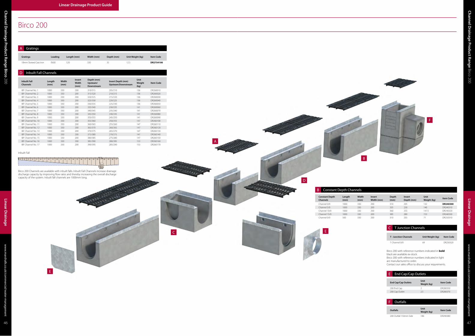
Ch
ann
el Drain
age Prod
uct Ran
ge B
irco 200w
ww
.marshalls.co.uk/com
mercial/w
ater-managem
ent
Linear Drainage Product Guide
Linear D
rainag
e
ww
w.m
arshalls.co.uk/comm
ercial/water-m
anagement
Ch
ann
el Drain
age Prod
uct Ran
ge Birco 200
Linear D
rainag
e
46 47
A
D
B
E
E
F
C
Birco 200
End Cap/Cap OutletsUnit Weight (kg)
Item Code
200 End Cap 2 DR280350
200 Cap Outlet 2.5 DR280370
OutfallsUnit Weight (kg)
Item Code
200 Outfall 150mm Side 186 DR290380
Gratings Loading Length (mm) Width (mm) Depth (mm) Unit Weight (kg) Item Code
18mm Slotted Cast Iron E600 520 330 35 12.5 DR2754100
Constant Depth Channels
Length (mm)
Width (mm)
InvertWidth (mm)
Depth (mm)
InvertDepth (mm)
Unit Weight (kg)
Item Code
Channel 0/0 1000 330 200 310 205 142 DR240300Channel 5/0 1000 330 200 335 230 140 DR240310
Channel 10/0 1000 330 200 360 255 147.5 DR240320
Channel 15/0 1000 330 200 385 280 153 DR240330
Channel 0/0 500 330 200 310 205 71 DR250310
A
D
B
E
F
T - Junction Channels Unit Weight (kg) Item Code
T-Channel 0/0 69 DR250320
Birco 200 with reference numbers indicated in bold black are available ex-stock.Birco 200 with reference numbers indicated in light are manufactured to order.Contact our sales office to discuss your requrements.
C
Inbuilt FallChannels
Length (mm)
Width (mm)
InvertWidth (mm)
Depth (mm)Upsteam/Downstream
Invert Depth (mm)Upsteam/Downstream
Unit Weight (kg)
Item Code
IBF Channel No. 1 1000 330 200 310/315 205/210 136 DR260010
IBF Channel No. 2 1000 330 200 315/320 210/215 136 DR260020
IBF Channel No. 3 1000 330 200 320/325 215/220 136 DR260030
IBF Channel No. 4 1000 330 200 325/330 220/225 136 DR260040
IBF Channel No. 5 1000 330 200 330/335 225/230 136 DR260050
IBF Channel No. 6 1000 330 200 335/340 230/235 141 DR260060
IBF Channel No. 7 1000 330 200 340/345 235/240 141 DR260070
IBF Channel No. 8 1000 330 200 345/350 240/245 141 DR260080
IBF Channel No. 9 1000 330 200 350/355 245/250 141 DR260090
IBF Channel No. 10 1000 330 200 355/360 250/255 147 DR260100
IBF Channel No. 11 1000 330 200 360/365 255/260 147 DR260110
IBF Channel No. 12 1000 330 200 365/370 260/265 147 DR260120
IBF Channel No. 13 1000 330 200 370/375 265/270 147 DR260130
IBF Channel No. 14 1000 330 200 375/380 270/275 147 DR260140
IBF Channel No. 15 1000 330 200 380/385 275/280 147 DR260150
IBF Channel No. 16 1000 330 200 385/390 280/285 153 DR260160
IBF Channel No. 17 1000 330 200 390/395 285/290 153 DR260170
Birco 200 Channels are available with inbuilt falls. Inbuilt Fall Channels increase drainage discharge capacity by improving flow rates and thereby increasing the overall discharge capacity of the system. Inbuilt fall channels are 1000mm long.
Inbuilt Fall
Constant Depth Channels
T Junction Channels
End Cap/Cap Outlets
Outfalls
Gratings
Inbuilt Fall Channels
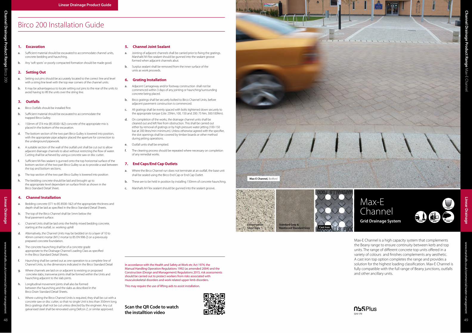
Max-E ChannelGrid Drainage System
Max-E Channel, Bedford
Max-E Channel is a high capacity system that complements the Beany range to ensure continuity between kerb and top units. The range of different concrete top units offered in a variety of colours and finishes complements any aesthetic. A cast iron top option completes the range and provides a solution for the highest loading classification. Max-E Channel is fully compatible with the full range of Beany junctions, outfalls and other ancillary units.
Standard Grey &Reinforced Standard Grey Cast Iron
ConservationSilver Grey
ww
w.m
arshalls.co.uk/comm
ercial/water-m
anagement
Ch
ann
el Drain
age Prod
uct Ran
ge M
ax-E Channel
Ch
ann
el Drain
age Prod
uct Ran
ge Birco 200
ww
w.m
arshalls.co.uk/comm
ercial/water-m
anagement
Linear Drainage Product Guide
Linear D
rainag
e
Linear D
rainag
e
48 49
Q10 170
Birco 200 Installation Guide
In accordance with the Health and Safety at Work etc Act 1974, the Manual Handling Operation Regulations 1992 (as amended 2004) and the Construction (Design and Management) Regulations 2015, risk assessments should be carried out to protect workers from risks associated with musculoskeletal disorders and work related upper limb disorders.
This may require the use of lifting aids to assist installation.
1. Excavation
a. Sufficient material should be excavated to accommodate channel units, concrete bedding and haunching.
b. Any ‘soft spots’ or poorly compacted formation should be made good.
2. Setting Out
a. Setting out pins should be accurately located to the correct line and level with a string line level with the top rear corners of the channel units.
b. It may be advantageous to locate setting out pins to the rear of the units to avoid having to lift the units over the string line.
3. Outfalls
a. Birco Outfalls should be installed first.
b. Sufficient material should be excavated to accommodate the trapped Birco Gulley.
c. 150mm of ST4 mix (BS 8500-1&2) concrete of the appropriate mix is placed in the bottom of the excavation.
d. The bottom section of the two part Birco Gulley is lowered into position, with the appropriate pipe adaptor placed the aperture for connection to the underground pipework.
e. A suitable section of the wall of the outfall unit shall be cut out to allow adjacent drainage channels to abut without restricting the flow of water. Cutting shall be achieved by using a concrete saw or disc cutter.
f. Sufficient M-Flex sealant is gunned onto the top horizontal surface of the bottom section of the two part Birco Gulley so as to provide a seal between the top and bottom sections.
g. The top section of the two part Birco Gulley is lowered into position
h. The bedding concrete should be laid and brought up to the appropriate level dependant on surface finish as shown in the Birco Standard Detail Sheet.
5. Channel Joint Sealant
a. Jointing of adjacent channels shall be carried prior to fixing the gratings. Marshalls’ M-Flex sealant should be gunned into the sealant groove formed when adjacent channels abut.
b. Surplus sealant shall be removed from the inner surface of the units as work proceeds.
4. Channel Installation
a. Bedding concrete (ST1 to BS 8500-1&2) of the appropriate thickness and depth shall be laid as specified in the Birco Standard Detail Sheets.
b. The top of the Birco Channel shall be 5mm below the final pavement surface.
c. Channel Units shall be laid onto the freshly mixed bedding concrete, starting at the outfall, i.e. working uphill
d. Alternatively, the Channel Units may be bedded on to a layer of 10 to 40mm cement mortar (M12 mortar to BS EN 998-2) on a previously prepared concrete foundation.
e. The concrete haunching shall be of a concrete grade appropriate to the Drainage Channel Loading Class as specified in the Birco Standard Detail Sheets.
f. Haunching shall be carried out as one operation to a complete line of Channel Units, to the dimensions indicated in the Birco Standard Detail
g. Where channels are laid on or adjacent to existing or proposed concrete slabs, transverse joints shall be formed within the Units and haunching adjacent to the slab joints.
h. Longitudinal movement joints shall also be formed between the haunching and the slabs as described in the Birco Drain Standard Detail Sheets.
i. Where cutting the Birco Channel Units is required, they shall be cut with a concrete saw or disc cutter, so that no single Unit is less than 350mm long. Birco gratings shall not be cut unless directed by the engineer. Any cut galvanised steel shall be renovated using Defcon Z, or similar approved.
6. Grating Installation
a. Adjacent Carriageway and/or footway construction shall not be commenced within 3 days of any jointing or haunching/surrounding concrete being placed.
b. Birco gratings shall be securely bolted to Birco Channel Units, before adjacent pavement construction is commenced.
c. All gratings shall be evenly spaced with bolts tightened down securely to the appropriate torque (Lite: 25Nm, 100, 150 and 200: 75 Nm, 300:100Nm).
d. On completion of the works, the drainage channel units shall be cleaned out and left free from obstruction. This shall be carried out either by removal of gratings or by high pressure water jetting (100-150 bar at 200 litres/min minimum). Unless otherwise agreed with the specifier, the slot openings shall be covered by timber boards or other method during jetting operations.
e. Outfall units shall be emptied.
f. The cleaning process should be repeated where necessary on completion of any remedial works.
7. End Caps/End Cap Outlets
a. Where the Birco Channel run does not terminate at an outfall, the base unit shall be sealed using the Birco End Cap or End Cap Outlet.
b. These are to be held in position by installing 150mm of concrete haunching.
c. Marshalls M-Flex sealant should be gunned into the sealant groove.
Scan the QR Code to watch the installtion video
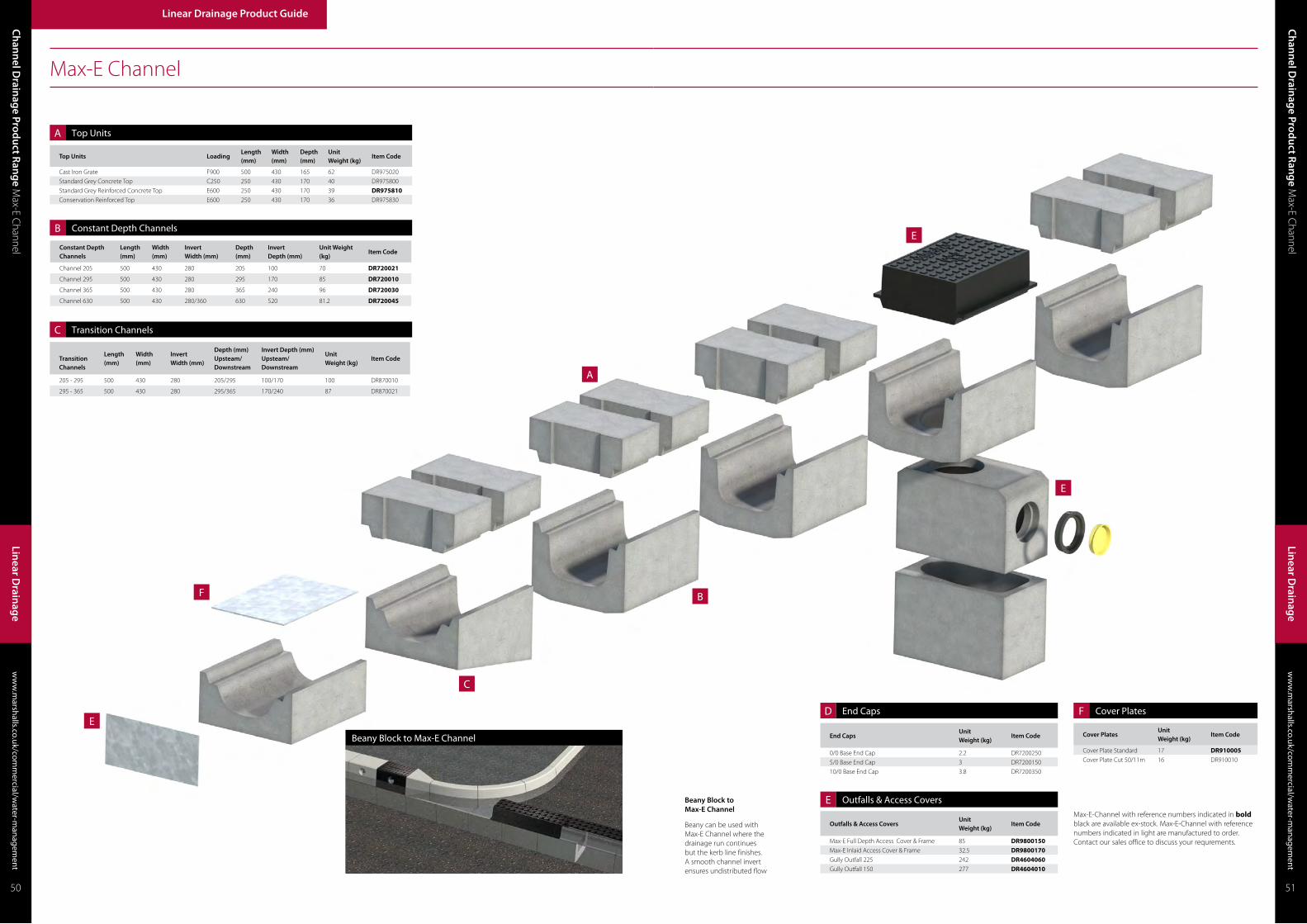
E
E
E
F
A
C
B
Max-E Channel
Top Units LoadingLength (mm)
Width (mm)
Depth (mm)
Unit Weight (kg)
Item Code
Cast Iron Grate F900 500 430 165 62 DR975020
Standard Grey Concrete Top C250 250 430 170 40 DR975800
Standard Grey Reinforced Concrete Top E600 250 430 170 39 DR975810Conservation Reinforced Top E600 250 430 170 36 DR975830
A
Transition Channels
Length (mm)
Width (mm)
Invert Width (mm)
Depth (mm)Upsteam/Downstream
Invert Depth (mm)Upsteam/Downstream
Unit Weight (kg)
Item Code
205 - 295 500 430 280 205/295 100/170 100 DR870010
295 - 365 500 430 280 295/365 170/240 87 DR870021
C
B
Constant Depth Channels
Length (mm)
Width (mm)
InvertWidth (mm)
Depth (mm)
InvertDepth (mm)
Unit Weight (kg)
Item Code
Channel 205 500 430 280 205 100 70 DR720021
Channel 295 500 430 280 295 170 85 DR720010
Channel 365 500 430 280 365 240 96 DR720030
Channel 630 500 430 280/360 630 520 81.2 DR720045
ww
w.m
arshalls.co.uk/comm
ercial/water-m
anagement
Ch
ann
el Drain
age Prod
uct Ran
ge M
ax-E Channel
Ch
ann
el Drain
age Prod
uct Ran
ge M
ax-E Channel
ww
w.m
arshalls.co.uk/comm
ercial/water-m
anagement
Linear Drainage Product Guide
Linear D
rainag
e
Linear D
rainag
e
50 51
Beany Block to Max-E Channel
Beany can be used with Max-E Channel where the drainage run continues but the kerb line finishes. A smooth channel invert ensures undistributed flow
Beany Block to Max-E Channel
Outfalls & Access CoversUnit Weight (kg)
Item Code
Max-E Full Depth Access Cover & Frame 85 DR9800150Max-E Inlaid Access Cover & Frame 32.5 DR9800170Gully Outfall 225 242 DR4604060Gully Outfall 150 277 DR4604010
E
End CapsUnit Weight (kg)
Item Code
0/0 Base End Cap 2.2 DR7200250
5/0 Base End Cap 3 DR7200150
10/0 Base End Cap 3.8 DR7200350
D F
Max-E-Channel with reference numbers indicated in bold black are available ex-stock. Max-E-Channel with reference numbers indicated in light are manufactured to order. Contact our sales office to discuss your requrements.
Cover PlatesUnit Weight (kg)
Item Code
Cover Plate Standard 17 DR910005Cover Plate Cut 50/11m 16 DR910010
End Caps
Outfalls & Access Covers
Cover Plates
Top Units
Constant Depth Channels
Transition Channels

InsituCast Concrete
Drexus XL Slot Drainage System
Drexus XL, Example
Marshalls NEW Drexus XL is a recycled polyethylene (PE) high capacity channel, ideally suited for high capacity heavy duty projects covering any load class from busy service yards and rail & docking ports, airports with severe dynamic transport loading to motorways and commercial outlets.
The high capacity system is designed to offer attenuation and storage facilities but also to achieve sufficient flow velocities at low gradient to ensure that the channels require minimal maintenance. Drexus XL’s In-Situ surface finish is designed to integrate seamlessly into concrete or black top surfaces.
Max-E Channel Installation Guide
In accordance with the Health and Safety at Work etc Act 1974, the Manual Handling Operation Regulations 1992 (as amended 2004) and the Construction (Design and Management) Regulations 2015, risk assessments should be carried out to protect workers from risks associated with musculoskeletal disorders and work related upper limb disorders.
This may require the use of lifting aids to assist installation.
5. Channel Joint Sealanta. Sufficient M-Seal bituminous mastic jointing compound should be
trowelled on to one end face of the Base Unit so that the joint will be well sealed when the next Unit is tamped into position.
b. Surplus sealant shall be removed from the inner surface of the Units as work proceeds.
6. Top Block Installationa. The string line should be set to the level of the top corner of Units.
b. Again, starting at the Outfall, the Units should be set directly onto a liberal quantity of stiff, cement mortar to completely fill the whole of the joint.
c. Cement mortar shall be Class M12 in accordance with BS EN 998-2 for applications up to and including D400 and should be M Bond epoxy mortar for higher loading applications.
d. The M Bond epoxy mortar should be mixed in accordance with the instructions on the container.
e. The Top Units should be tamped into position close to previously laid Units and the alignment checked.
f. The levels should be checked using the string line and a spirit level.
g. In addition, the general alignment should be checked from all directions as each Unit is laid. Any Unit deviating by more than 3mm in 3m from line and level shall be made good by lifting and relaying.
h. The inside and outside of the joints between Base and Top Units should be pointed and cleaned out with a brush or rag as work proceeds.
i. Where cutting is necessary, one or two Units shall be cut so that no single Unit is less than 200mm in length. All cutting and trimming of the Units shall be carried out with a concrete saw or disc cutter.
j. It is not necessary for Top and Base Unit vertical joints to line up
k. The front and rear concrete haunching is installed to the dimensions shown on the standard detail or drawing.
4. Base Unit Installationa. Bedding concrete of the appropriate mix and to the appropriate
thickness and depth shall be laid
b. Base Units shall be laid onto the freshly mixed bedding concrete, starting at the outfall, i.e. working uphill
c. Alternatively, the Base Units may be bedded on to a layer of 10 to 40mm cement mortar on a previously prepared concrete foundation.
d. Where cutting is necessary, one or two Units shall be cut so that no single Unit is less than 200mm in length.
e. All cutting and trimming of the Units shall be carried out with a concrete saw or disc cutter.
1. Excavationa. Sufficient material should be excavated to accommodate Top and Base
Units, concrete bedding and haunching.
b. Any ‘soft spots’ or poorly compacted formation should be made good.
2. Setting Outa. Setting out pins should be accurately located to the correct line and level
with a string line level with the top front corners of the Base Units.
b. It may be advantageous to locate setting out pins to the rear of the Units to avoid having to lift the Units over the string line.
c. Sufficient setting out pins should be inserted where Max-E Channel Bases are laid on horizontal curves
3. Outfalls a. Max-E Channel Outfalls should be installed first.
b. Sufficient material should be excavated to accommodate the Trapped Max-E Channel Gulley
c. 125mm of concrete of the appropriate mix is placed in the bottom of the excavation
d. The bottom section of the two part Max-E Channel Gulley is lowered into position
e. Sufficient M-Flex sealant is gunned onto the top horizontal surface of the bottom section of the two part Max-E Channel Gulley so as to provide a seal between the top and bottom sections
f. The top section of the two part Max-E Channel Gulley is lowered into position
g. The bedding concrete should be laid and brought up flush to the top Max-E Channel Gulley
h. The Max-E Channel Base Outfall Block should be set directly onto a liberal quantity of stiff, cement mortar
i. The Cast iron Access Cover & Frame Units should be set directly onto a liberal quantity of stiff, cement mortar to completely fill the whole of the joint.
7. End Capsa. Where the Max-E Channel run does not terminate at an outfall, the base
unit shall be sealed using the Max-E-Channel End Cap.
b. The End Cap shall be securely placed against the vertical end of the base unit and haunched with fresh concrete.
8. Pavement Installationa. Where Max-E Channel is laid on or adjacent to existing or proposed
concrete slabs, transverse joints shall be formed within the units and haunching adjacent to the slab joints and also longitudinal movement joints between the haunching and the slabs.
b. Where necessary, the Top Unit drainage openings shall be protected against the ingress of material during concreting operations by covering with Waterproof Cloth Tape.
Scan the QR Code to watch the installtion video
ww
w.m
arshalls.co.uk/comm
ercial/water-m
anagement
Ch
ann
el Drain
age Prod
uct Ran
ge D
rexus XL
Ch
ann
el Drain
age Prod
uct Ran
ge M
ax-E Channel
ww
w.m
arshalls.co.uk/comm
ercial/water-m
anagement
Linear Drainage Product Guide
Linear D
rainag
e
Linear D
rainag
e
52 53
Q10 170
InsituCast Concrete

Drexus XL Channel
ww
w.m
arshalls.co.uk/comm
ercial/water-m
anagement
Ch
ann
el Drain
age Prod
uct Ran
ge D
rexus XL
Ch
ann
el Drain
age Prod
uct Ran
ge D
rexus XLw
ww
.marshalls.co.uk/com
mercial/w
ater-managem
ent
Linear Drainage Product Guide
Linear D
rainag
e
Linear D
rainag
e
54 55
Constant DepthChannel
LoadingLength (mm)
Width (mm)
InvertWidth (mm)
Depth (mm)
Invert Depth (mm)
Unit Weight (kg)
In-situ Top
325 B125 - F900 2000 300 188 585 505 13 DR537010
425 B125 - F900 2000 483 319 723 631 20 DR537020
525 B125 - F900 2000 543 379 813 721 23 DR537030
675 B125 - F900 2000 644 482 949 857 27 DR537040
825 B125 - F900 2000 707 586 1106 1014 32 DR537050
Transition ChannelsLength (mm)
Width (mm)
InvertWidth (mm)
Depth (mm)
Invert Depth (mm)
Unit Weight (kg)
In-situ Top
425-325 (Reducer) 478 489/300 322/214 542/348 463/292 3.25 DR538110
525-425 (Reducer) 478 543/489 379/322 592/542 527/463 4.5 DR538120
675-525 (Reducer) 478 644/543 476/379 732/592 664/527 5.8 DR538130
825-675 (Reducer) 478 706/644 582/476 890/732 821/664 7.5 DR538140
325-425 (Enlarger) 478 300/489 214/322 348/542 292/463 3.5 DR538010
425-525 (Enlarger) 478 543/489 322/379 542/592 463/527 4.6 DR538020
525-675 (Enlarger) 478 543/644 379/476 592/732 527/664 5.9 DR538030
675-825 (Enlarger) 478 644/706 476/582 732/890 664/821 7.6 DR538040
Outfall AccessoriesUnit Weight (kg)
Item Code
325 AC Connector - RH 2.6 DR538410
425 AC Connector - RH 3.9 DR538420
525 AC Connector - RH 5 DR538430
675 AC Connector - RH 7 DR538440
825 AC Connector - RH 9 DR538450
325 AC Connector - LH 2.5 DR538510
425 AC Connector - LH 3.9 DR538520
525 AC Connector - LH 4.9 DR538530
675 AC Connector - LH 6.9 DR538540
825 AC Connector - LH 9 DR538550
325-525 Access Chamber & Cover 11.5 DR538905
325-525 AC & Silt Box 26.5 DR538910
675-825 Access Chamber & Cover 15 DR538920
675-825 AC & Silt Box 41.5 DR538925
A
A
B
B
CD
D
DDrexus XL with reference numbers indicated in bold black are available ex-stock.Drexus XL with reference numbers indicated in light are manufactured to order.Contact our sales office to discuss your requrements.
End CapsUnit Weight (kg)
Item Code
325 End Cap 1 DR537910
425 End Cap 2.5 DR537920
525 End Cap 3 DR537930
675 End Cap 4.5 DR537940
825 End Cap 5.5 DR537950
C End Caps
Outfalls Accessories
Constant Depth Channel
Transition Channels

Max-E Channel, Bedford
Birco 100, Manchester
Birco 100, Manchester
Pave Drain, Holborn
Mono Slot Drain, Celtic Park
Birco Lite, London Bridge Station
Birco 100, ElyDuo Slot Drain, Manchester
Ch
ann
el Drain
age Prod
uct Ran
ge D
rexus XLw
ww
.marshalls.co.uk/com
mercial/w
ater-managem
ent
Linear Drainage Product Guide
Linear D
rainag
e
Linear D
rainag
eLin
ear Drain
age Prod
uct Guid
ew
ww
.marshalls.co.uk/com
mercial/w
ater-managem
ent
Drexus XL Installation Guide
56 57
In accordance with the Health and Safety at Work etc Act 1974, the Manual Handling Operation Regulations 1992 (as amended 2004) and the Construction (Design and Management) Regulations 2015, risk assessments should be carried out to protect workers from risks associated with musculoskeletal disorders and work related upper limb disorders.
This may require the use of lifting aids to assist installation.
1. Excavation & Setting Outa. Mark out the required line of drainage.
b. Mark out the required level for the system.
c. Excavate trench with an additional depth and width of 150mm (C250/D400) or 200mm (F900) each side than the respective dimensions of the selected Channel and Lid. For channel depths see the Marshalls drainage design guide. Suitable trench support and edge protection should be used if identified by the site risk assessment.
4. End Cap and End Cap Outleta. The channels should be terminated with either an end cap or end cap
outlet. The end cap is universal for both male and female ends of the channel whereas the end cap outlet is specific.
b. When terminating the run at an access chamber/outfall an end cap outlet should be used to enter the chamber it can be trimmed to suit. The end cap outlet has also been designed to transition to standard drainage twin wall pipe by way of a standard coupling.
5. Surface Installationa. Prior to the next pour of concrete reinforcement bars should be installed if
required by the pavement design. Engineering advice should be sought for specific guidance.
b. Ensure the bungs (colour tbc) are in place to prevent concrete ingress.
c. Continue to pour concrete to surface level with the top of the rubber bungs.
d. Finish the concrete surface with power float type devices which will move over the rubber bungs.
e. When the concrete has set the inlet bungs can be removed, this is best achieved by piercing the units and levering along the inlet.
f. After concreting the system should not be loaded with passing traffic until the concrete has had time to fully cure.
2. Access and Outfall Chamber installationa. Excavate to formation level
b. Install trench support and excavation access as required
c. Prepare formation by trimming or laying blinding concrete
d. Position chamber or silt box unit in excavation
e. Set chamber to correct level and orientation using non-compressible setting block
f. Install formwork and supports for the concrete surround
g. Provide temporary support to the unit as required to maintain position during placement of base concrete
h. Place concrete around chamber unit to form base and part of the vertical surround. The surround should extend no more than 75 mm up the side of the chamber unit
i. Check level and orientation, adjust as required
j. After initial set has been achieved, install additional chamber units and connection pipework in position as required
k. Extend formwork and place concrete generally as items 6, 7, 8 & 9 to the top surface of the chamber
l. When the concrete has achieve strength, strike formwork and remove
m. Backfill chamber to the underside of the final pavement construction or as required
n. Bed and haunch cover and frame using a minimum mortar Class 12 to BS EN 998-2 or a similar proprietary bedding compound suitable for application and loading. Level and adjust as required.
3. Drexus XL Unit Installationa. Line the trench bottom with a 150mm (C250/D400) or 200mm (F900)
deep layer of semi-dry concrete to provide a bed for the Channel. The mix is specified in the drainage design guide.
b. Manually lift the channel into position if safe to do so. The channel can be lifted by strop if manual handling is unsuitable. Seek further guidance on lifting equipment from the relevant supplier.
c. It is preferred but not essential to have the male end of the coupling at the start of the run.
d. Align the horizontal locators at the channel couplings; these can then be fixed in place with a nut and bolt or a zip tie.
e. Tamp the top of the Channel along its length until it is to line and level.
f. If necessary pin the feet into position by placing a suitable pin (e.g. setting out pin) into the V notch of the channels feet. The channel can also be braced to the walls of the trench; this will help avoid movement of the system during the concrete pour.
g. Pour the concrete evenly each side of the channel until the feet are fully submerged.
h. Remove feet pins prior to the concrete setting if they are required.
i. Leave the concrete to set this should usually achieve enough stiffness in 12 hours.

Combined Kerb & Drainage Product Range
Standard Grey
Mono Beany® One Piece Combined Kerb and Drainage System
Mono Beany, A21, East Sussex
An innovative, concrete single piece combined kerb and drainage solution. Mono Beany is a low to medium capacity system which combines strength and aesthetics through Marshalls’ high strength M-Tech concrete. A recycled inner plastic core provides hydraulic flow benefits at low capacities. Available in two depths and in both Half Battered and 45˚Splayed profiles with a range of accessories to provide a comprehensive drainage system which carries the BSI Kitemark.
Linear Drainage Product Guide
Linear D
rainag
e Product G
uide Com
bined Kerb & Drainage Product Range
CK
& D
rainag
ew
ww
.marshalls.co.uk/com
mercial/w
ater-managem
ent
CK
& D
rainag
ew
ww
.marshalls.co.uk/com
mercial/w
ater-managem
entC
omb
ined
Kerb
& D
rainag
e Product R
ang
e Mono Beany
58 59
Q10 190

Mono Beany
Mono Beany with reference numbers indicated in bold black are available ex-stock.Mono Beany with reference numbers indicated in light are manufactured to order.Contact our sales office to discuss your requrements.
B
B
A
A
A
E
E
F
F
F
Transition Channels
Length (mm)
Width (mm)
Height (mm)
Invert Depth (mm)Upstream/Downstream
Unit Weight (kg)
Item Code
Half Battered 502 - 321 Transition RH 1000 150 502 221/402 107 DR663320
503 - 321 Transition LH 1000 150 502 221/403 107 DR663321
45o Splayed 503 - 321 Transition RH 1000 150 502 221/403 107 DR663326
502 - 321 Transition LH 1000 150 502 221/402 107 DR663305
C
C
C
Road Crossing Accessories
Length (mm)
Width (mm)
Height (mm)
Unit Weight (kg)
Item Code
Half Battered Centre Stone 321 1000 150 202 40 DR663110Centre Stone 502 1000 150 383 50 DR663115Right Hand 321 1000 150 202/321 50 DR663090Right Hand 502 1000 150 383/502 60 DR663095
Left Hand 321 1000 150 202/321 50 DR663100Left Hand 502 1000 150 383/502 60 DR663105
45o Splayed 5/9 Internal Radius 321 490 150 321 20 DR663140
Centre Stone 321 1000 150 252 40 DR663310
Centre Stone 502 1000 150 433 50 DR663315
Right Hand 321 1000 150 252/321 50 DR663290
Right Hand 502 1000 150 433/502 60 DR663295
Left Hand 321 1000 150 252/321 50 DR663300
Left Hand 502 1000 150 433/502 60 DR663305
D
Radial ChannelsLength (mm)
Width (mm)
Height (mm)
Unit Weight (kg)
Item Code
Half Battered 5/9 Internal Radius 321 490 150 321 20 DR663050
5/9 Internal Radius 502 490 150 502 30 DR663060
5/9 External Radius 321 490 150 321 20 DR663070
5/9 External Radius 502 490 150 502 30 DR663080
20/10 Internal Radius 321 490 150 321 20 DR663055
20/10 Internal Radius 502 490 150 502 30 DR663065
20/10 External Radius 321 490 150 321 20 DR663075
20/10 External Radius 502 490 150 502 30 DR663085
45o Splayed 5/9 Internal Radius 321 490 150 321 20 DR663140
5/9 Internal Radius 502 490 150 502 30 DR663150
5/9 External Radius 321 490 150 321 20 DR663160
5/9 External Radius 502 490 150 502 30 DR663170
20/10 Internal Radius 321 490 150 321 20 DR663145
20/10 Internal Radius 502 490 150 502 30 DR663155
20/10 External Radius 321 490 150 321 20 DR663165
20/10 External Radius 502 490 150 502 30 DR663175
End Cap/Cap OutletsUnitWeight (kg)
Item Code
End Cap for 321 System 1 DR664235End Cap for 502 System 1 DR664240Cap Outlet for 321 System 1 DR664225
Cap Outlet for 502 System 1 DR664230
Outfalls & AccessoriesUnitWeight (kg)
Item Code
Inline Slide Outfall 80 DR664180Half Battered Access Cover 40 DR66401045o Splayed Access Cover 40 DR664020Rodding Box for 321 System 20 DR664185Rodding Box for 502 System 30 DR664190
Constant Depth Channels
Length (mm)
Width (mm)
Height (mm)
Unit Weight (kg)
Item Code
Half Battered 1000 150 321 69 DR663030500 150 321 34.5 DR6630351000 150 502 91 DR663040500 150 502 45.5 DR663045
45o Splayed 1000 150 321 64 DR663120500 150 321 32 DR663125
1000 150 502 86 DR663130500 150 502 43 DR663135
Linear Drainage Product GuideC
K &
Drain
age
ww
w.m
arshalls.co.uk/comm
ercial/water-m
anagement
Com
bin
ed K
erb &
Drain
age Prod
uct Ran
ge M
ono Beany
Com
bin
ed K
erb &
Drain
age Prod
uct Ran
ge M
ono BeanyC
K &
Drain
age
ww
w.m
arshalls.co.uk/comm
ercial/water-m
anagement
60 61
Road Crossing Accessories
Radial Channels
Constant Depth Channels
Transition Channels
End Cap/Cap Outlets Outfalls & Accessories

Mono Beany Case Study - M1
Linear Drainage Product GuideC
K &
Drain
age
ww
w.m
arshalls.co.uk/comm
ercial/water-m
anagement
Com
bin
ed K
erb &
Drain
age Prod
uct Ran
ge Case Study
w
Com
bin
ed K
erb &
Drain
age Prod
uct Ran
ge M
ono BeanyC
K &
Drain
age
ww
w.m
arshalls.co.uk/comm
ercial/water-m
anagement
Mono Beany Installation Guide
In accordance with the Health and Safety at Work etc Act 1974, the Manual Handling Operation Regulations 1992 (as amended 2004) and the Construction (Design and Management) Regulations 2015, risk assessments should be carried out to protect workers from risks associated with musculoskeletal disorders and work related upper limb disorders.
This may require the use of lifting aids to assist installation.
4. Mono Beany Unit Installationa. Bedding concrete (ST1 to BS 8500-1&2) of the appropriate thickness and
depth shall be laid
b. Mono Beany Units shall be laid onto the freshly mixed bedding concrete, starting at the outfall, i.e. working uphill
c. Alternatively, the Mono Beany Units may be bedded on to a layer of 10 to 40mm cement mortar (M12 mortar to BS EN 998-2) on a previously prepared concrete foundation.
d. Where cutting is necessary, one or two Units shall be cut so that no single Unit is less than 200mm in length and no cuts shall be within 50mm of the inlet aperture. No cutting shall impair the stability of the Unit.
e. All cutting and trimming of the Units shall be carried out with an appropriate cutting tool.
1. Excavationa. Sufficient material should be excavated to accommodate the
Units, concrete bedding and haunching.
b. Any ‘soft spots’ or poorly compacted formation should be made good.
2. Setting Outa. Setting out pins should be accurately located to the correct line and
level with a string line level placed to the rear of the kerb.
b. Sufficient setting out pins should be inserted where Mono Beany Units are laid on horizontal curves.
3. Outfalls a. Mono Beany Outfalls should be installed first.
b. Sufficient material should be excavated to accommodate the Trapped Mono Beany Gulley
c. 125mm of ST4 mix (BS 8500-1&2) concrete of the appropriate mix is placed in the bottom of the excavation
d. The bottom section of the two part Mono Beany Outfall is lowered into position
e. Sufficient M-Flex sealant is gunned onto the top horizontal surface of the bottom section of the two part Beany Outfall so as to provide a seal between the top and bottom sections
f. The bedding concrete should be laid and brought up flush to the top of the Mono Beany Outfall.
g. The Cast iron Access Cover & Frame Units should be set directly onto a liberal quantity of stiff, cement mortar to completely fill the whole of the joint.
5. Mono Beany Joint Sealanta. Sufficient Marshalls’ M-Flex sealant should be gunned into the sealant
groove at either end of the unit.
7. Pavement Installationa. Where Mono Beany is laid on or adjacent to existing or proposed concrete
slabs, transverse joints shall be formed within the units and haunching adjacent to the slab joints and also longitudinal movement joints between the haunching and the slabs.
b. Where necessary, the Unit drainage openings shall be protected against the ingress of material during concreting operations by covering with Waterproof Cloth Tape.
6. Mono Beany End Capa. Where the Mono Beany run does not terminate at an outfall, the base unit
shall be sealed using the Mono Beany End Cap.
b. The End Cap shall be securely placed against the vertical end of the base unit and haunched with fresh concrete (ST1 mix to BS 8500-1&2).
Scan the QR Code to watch the installtion video
62 63
Marshalls supplied 15,000 linear metres of Mono Beany one-piece combined kerb and drainage to the new M1 smart motorway scheme.
Challenge The road network is a crucial part of our national transport system and failures to improve these networks increases cost, hinders employment opportunities and makes it harder to do business.
Congestion is already a serious problem on the M1 between junctions 28 and 31 which carries around 95,000 vehicles per day.
The challenge was to install new infrastructure, including drainage attenuation, with minimal disruption and to select a suitable product engineered to help contractors meet deadlines. This would ensure the M1 was open and running to its full capacity within the project timescales. The client also needed to keep within budget and didn’t want to pay for a costly over-engineered system.
Solution Marshalls was chosen to supply linear drainage to the project. Mono Beany is Marshalls’ first one-piece combined kerb and drainage system made with ultra-tough M-Tech concrete which has been proven to significantly reduce installation time.
This innovative product is available in two depths which both have a recycled inner plastic core to provide hydraulic flow benefits at low and medium capacities. Each one metre unit can carry up to 40 tonnes (Class D400) when trafficked. The inlet apertures are divergent and angled at 45° to prevent blockages and maximise drainage efficiency. These features ensure surface water is cleared rapidly and internal flow is smooth and efficient.
The hydraulic capacity requirements varied along the run and therefore a mix of Mono Beany 321 and 502 units were required as this was deemed more cost-effective. Marshalls also used its expertise to develop a new transition unit to complete the M1 scheme as part of the Highways Agency’s focus on innovation. This was developed in order to create a smooth hydraulic transition from a 502 to a 321 Mono Beany unit, which reduced the hydraulic capacity, while coming within budget.
Client: Highways England
Contractor:Costain
Engineer:Mouchel (Manchester)
Marshalls products used:• 15,000 linear metres of
Mono Beany• Bespoke transition unit

Mini Beany® Combined Kerb and Drainage System
Linear Drainage Product Guide
Mini Beany, Conservation, Bedford
CK
& D
rainag
ew
ww
.marshalls.co.uk/com
mercial/w
ater-managem
entC
omb
ined
Kerb
& D
rainag
e Product R
ang
e Mini Beany
Com
bin
ed K
erb &
Drain
age Prod
uct Ran
ge Case Study
CK
& D
rainag
ew
ww
.marshalls.co.uk/com
mercial/w
ater-managem
ent
Mini Beany is a low to medium capacity combined kerb and drainage system which evolved from the successful Beany range. The robust concrete construction makes this the ideal choice for areas of heavy or abnormally heavy wheel loads. Available in a choice of top finishes to complement a wide range of projects, from urban to rural.
Standard GreyConservation Silver Grey
64 65
Benefit Costain initially anticipated it would lay 240 metres of Mono Beany per day, however using the revolutionary, easy-to-install Mono Beany system the installation time was considerably reduced, with 340 metres installed per day to the scheme.
Malcolm Bell, Construction Manager from Costain said: “Due to how quickly we were able to install the innovative Mono Beany system there was an increased demand on deliveries to site. Marshalls offered a reliable and guaranteed supply throughout the project, delivering three to four loads per week direct-to-site, often delivering two loads per day. This helped to ensure we met our completion deadlines and kept works disruption to a minimum.
“Working with Marshalls also offered Costain a dedicated and knowledgeable design team to meet our requirements for this scheme.
“These are all important factors when tasked with installing over nine miles of drainage to a major strategic route connecting people, communities and businesses.”
In the longer term this scheme will help relieve congestion and smooth traffic flow along this stretch of the M1, improving safety and journey times for commuters. These benefits will also support economic development in the region.
Responding to the recent announcement by Highways England that there will be a £1.5bn investment in smart motorway schemes David Jackson, Trading Drainage Director at Marshalls said: “Marshalls is already engaged in a number of smart motorway schemes as part of this investment, offering design expertise on a wide range of suitable products.
“As the UK’s leading supplier of hard landscaping materials, we are committed to developing effective water management and linear drainage solutions to meet the needs of contractors.
“Having already supplied Junctions 28-31 of the M1, we are poised for further involvement to improve the road network and have the capacity and capability to deal with further orders.”
Q10 190

B
A
A
F
E
I
G
A1
C
B
Base ChannelsLength (mm)
Width (mm)
InvertWidth (mm)
Depth (mm)
InvertDepth (mm)
Unit Weight (kg)
Item Code
210 Press Chan 1000 280 150 210 110 102 DR696010260 Press Chan 1000 280 150 260 160 109 DR697010310 Press Chan 1000 280 150 310 210 122 DR698010360 Press Chan 1000 280 150 360 160 144 DR699010210 Press Chan 500 280 150 210 110 51 DR696020260 Press Chan 500 280 150 260 160 55 DR697020310 Press Chan 500 280 150 310 210 61 DR698020360 Press Chan 500 280 150 360 260 77 DR699020
Linear Drainage Product GuideC
K &
Drain
age
ww
w.m
arshalls.co.uk/comm
ercial/water-m
anagement
Com
bin
ed K
erb &
Drain
age Prod
uct Ran
ge M
ini Beany
Com
bin
ed K
erb &
Drain
age Prod
uct Ran
ge M
ini BeanyC
K &
Drain
age
ww
w.m
arshalls.co.uk/comm
ercial/water-m
anagement
Mini Beany
A A1
Top BlocksLength (mm)
Width (mm)
Height (mm)
Unit Weight (kg)
Item Code
HB standard Grey 1000 250 240 95 DR672010HB standard Grey 500 250 240 43 DR67202045° SP Standard Grey 1000 250 240 98 DR67204045° SP Standard Grey 500 250 240 43 DR672050
Bull Nose Conservation 1000 250 240 139 DR931210
Bull Nose Conservation 500 250 240 69.5 DR931211
Road Crossing Accessories
Length (mm)
Width (mm)
Height (mm)
Unit Weight (kg)
Item Code
Drop Kerb LH 1000 250 240/135 82 DR689920Drop Kerb RH 1000 250 240/135 82 DR689930Drop Kerb Centre Stone 1000 250 135 70 DR689940Conservation Centre Stone 1000 250 135 70 DR931450
66 67
C
Transition Channels
Length (mm)Width (mm)
Invert Width (mm)
Depth (mm)Upsteam/Downstream
Invert Depth (mm)Upsteam/Downstream
Unit Weight (kg)
Item Code
210 - 260 500 280 150 210/260 110/160 54 DR696330260 - 310 500 280 150 260/310 160/310 61 DR697330
310 - 360 500 280 150 310/360 310/360 77 DR698330
Mini Beany with reference numbers indicated in bold black are available ex-stock.Mini Beany with reference numbers indicated in light are manufactured to order.Contact our sales office to discuss your requrements.
Access CoversUnit Weight (kg)
Item Code
HB Access Cover N/S 40 DR69101045° SP Access Cover N/S 40 DR691015HB Access Cover O/S 40 DR69102045° SP Access Cover O/S 40 DR691025Bull Nose Access Cover N/S 40 DR691027
F
E
G
End Cap/Cap OutletsUnit Weight (kg)
Item Code
210 End Cap 1 DR696310260 End Cap 1 DR697310310 End Cap 1 DR698310
360 End Cap 1 DR699310
210 Cap Outlet 2 DR696320
260 Cap Outlet 2 DR697320
310 Cap Outlet 2 DR698320
360 Cap Outlet 2 DR699320
Outfalls Unit Weight (kg) Item Code
Inline Side Outfall 150 DR689000Inline End Outfall 142 DR689010
Slit Box 72 DR689910Gully Outfall 150 277.25 DR460401Gully Outfall 225 242.25 DR460406Gully Outfall 150 Outlet 340.5 DR460400
Gully Outfall 225 Outlet 305.5 DR460405
D
Radial Base ChannelsUnit Weight (kg)
Item Code
210 Base 30/10 51 DR696110
210 Base 9/6 51 DR696120
260 Base 30/10 55 DR697110
260 Base 9/6 55 DR697120
310 Base 30/10 61 DR698110
310 Base 9/6 61 DR698120
360 Base 30/10 77 DR699110
360 Base 9/6 77 DR699120
Channel Transitions
End Cap/Cap Outlets
Access Covers
H
Cover Plates Unit Weight (kg) Item Code
Cover Plate 500 mm 12 DR691030Cover Plate 1000 mm 6 DR691040Cover Plate 30/10 6 DR691050
Cover Plate 9/6 6 DR691060
Cover Plates
Outfalls
I
Cable Duct Blocks Unit Weight (kg) Item Code
HB Cable Duct Block 3 DR689900
45° SP Cable Duct Block 3 DR689905
Cable Duct Blocks
Top Blocks
Base Channels
Transition Channels
Road Crossing Accessories

Linear Drainage Product Guide
Beany Block, Newcastle
CK
& D
rainag
ew
ww
.marshalls.co.uk/com
mercial/w
ater-managem
entC
omb
ined
Kerb
& D
rainag
e Product R
ang
e Beany Block
Com
bin
ed K
erb &
Drain
age Prod
uct Ran
ge M
ini BeanyC
K &
Drain
age
ww
w.m
arshalls.co.uk/comm
ercial/water-m
anagement
The original and the largest combined kerb and drainage system on the market. Trusted and proven over more than 30 years with over 1 million linear meters installed and working. A two piece concrete system available in either standard or textured finishes combines the largest hydraulic capacity with the strongest loading classification. Supported by a range of accessories to deliver a flexible, versatile and aesthetically appealing solution for a variety of projects.
Mini Beany Installation Guide
In accordance with the Health and Safety at Work etc Act 1974, the Manual Handling Operation Regulations 1992 (as amended 2004) and the Construction (Design and Management) Regulations 2015, risk assessments should be carried out to protect workers from risks associated with musculoskeletal disorders and work related upper limb disorders.
This may require the use of lifting aids to assist installation.
1. Excavationa. Sufficient material should be excavated to accommodate Top and Base
Units, concrete bedding and rear concrete haunch.
b. Any ‘soft spots’ or poorly compacted formation should be made good.
2. Setting Outa. Setting out pins should be accurately located to the correct line and level
with a string line level with the top front corners of the Base Units.
b. It may be advantageous to locate setting out pins to the rear of the Units to avoid having to lift the Units over the string line.
c. Sufficient setting out pins should be inserted where Mini Beany Blocks are laid on horizontal curves
3. Outfalls a. Mini Beany Outfalls should be installed first.
b. Sufficient material should be excavated to accommodate the required Mini Beany outfall unit
i. Inline Side Outfall Unit
ii. Inline End Outfall Unit
iii. High Capacity Outfall
c. 125mm of ST4 mix (BS 8500-1&2) concrete of the appropriate mix is placed in the bottom of the excavation
d. The bottom section of the required Mini Beany Gulley is lowered into position
e. Sufficient M-Flex sealant is gunned onto the top horizontal surface of the bottom section of the two part Mini Beany Gulley so as to provide a seal between the top and bottom sections
f. The top section of the two part Mini Beany Gulley is lowered into position
g. The bedding concrete should be laid and brought up flush to the top of the Mini Beany Gulley
h. The Mini Beany Cast iron Access Cover & Frame Units located on top of the outfall unit should be set directly onto a liberal quantity of stiff, cement mortar to completely fill the whole of the joint.
i. Mini Beany Access Covers and Frames are hinged and handed to the direction of the traffic, specified “nearside” and “offside”.
5. Channel Joint Sealanta. Sufficient M-Seal bituminous mastic jointing compound should be
trowelled on to one end face of the Base Unit so that the joint will be well sealed when the next Unit is tamped into position.
b. Surplus sealant shall be removed from the inner surface of the Units as work proceeds.
6. Top Block Installationa. The string line should be set to the level of the top corner of Units.
b. Again, starting at the Outfall, the Units should be set directly onto a liberal quantity of stiff, cement mortar to completely fill the whole of the joint.
c. Cement mortar shall be Class M12 in accordance with BS EN 998-2.
d. The Top Blocks should be tamped into position close to previously laid Units and the alignment checked.
e. The levels should be checked using the string line and a spirit level.
f. In addition, the general alignment should be checked from all directions as each Block is laid. Any Unit deviating by more than 3mm in 3m from line and level shall be made good by lifting and relaying.
g. The inside and outside of the joints between Base and Top Units should be pointed and cleaned out with a brush or rag as work proceeds.
h. Where cutting is necessary, one or two Units shall be cut so that no single Unit is less than 200mm in length. All cutting and trimming of the Units shall be carried out with a concrete saw or disc cutter.
i. It is not necessary for Top Block and Base Unit vertical joints to line up
j. The rear concrete haunching is installed to within 50mm of the top of the Top Block
4. Base Unit Installationa. Bedding concrete (ST1 to BS 8500-1&2) of the appropriate
thickness and depth shall be laid
b. Base Units shall be laid onto the freshly mixed bedding concrete, starting at the outfall, i.e. working uphill
c. Alternatively, the Base Units may be bedded on to a layer of 10 to 40mm cement mortar (M12 mortar to BS EN 998-2) on a previously prepared concrete foundation.
d. Where cutting is necessary, one or two Units shall be cut so that no single Unit is less than 200mm in length and no cuts shall be within 50mm of the inlet aperture. No cutting shall impair the stability of the Unit.
e. All cutting and trimming of the Units shall be carried out with a concrete saw or disc cutter.
Beany® BlockCombined Kerb and Drainage System
Standard GreyConservation Silver Grey
Scan the QR Code to watch the installtion video
68 69
Q10 190Q25 800

A
F
E
C
C
G
G
I
J
Beany Block with reference numbers indicated in bold black are available ex-stock.Beany Block with reference numbers indicated in light are manufactured to order.Contact our sales office to discuss your requrements.
Linear Drainage Product GuideC
K &
Drain
age
ww
w.m
arshalls.co.uk/comm
ercial/water-m
anagement
Com
bin
ed K
erb &
Drain
age Prod
uct Ran
ge Beany Block
Com
bin
ed K
erb &
Drain
age Prod
uct Ran
ge Beany Block
CK
& D
rainag
ew
ww
.marshalls.co.uk/com
mercial/w
ater-managem
ent
Beany Block
A B
C
D
Top BlocksLength (mm)
Width (mm)
Height (mm)Unit Weight (kg)
Item Code
HB Straight Back 500 430 295 71 DR700020HB Straight Back Conservation 500 430 295 75 DR9300023
HB Straight Back Low Hole 500 430 295 71 DR700030
HB Symmetrical Low Hole 500 430 295 71 DR700035
HB Symmetrical 500 430 295 73 DR70001045 Splayed Straight Back 500 430 295 76 DR700060
Radial Tops Unit Weight (kg) Item Code
HB 50/20m Ext 71 DR730020HB 19/11m Ext 71 DR730030HB Cut 10/8m Ext 71 DR730040
HB Cut 50/20m Int 71 DR730210
HB Cut 19/11m Int 71 DR730230HB St Back 50/20m Ext 69 DR740020HB St Back 19/11m Ext 69 DR740030HB St Back Cut 10/8m Ext 69 DR740040
HB St Back Cut 7/6m Ext 69 DR740050
HB St Back Cut 50/20 Int 69 DR740210
HB St Back Cut 19/11 Int 69 DR740230
HB St Back 90degree Corner Int 174 DR895250
HB St Back 90degree Corner Ext 174 DR895255
HB St Back 45degree Corner Int 174 DR895500
HB St Back 45degree Corner Ext 174 DR895505
45⁰ SP Str Bk Cut 50/20 Int 76 DR751009
45⁰ SP Str Bk Cut 50/20 Ext 76 DR751010
45⁰ SP Str Bk Cut 19/11 Ext 76 DR751031
45⁰ SP Str Bk Cut 10/8 Ext 76 DR751040
Radial ChannelsUnit Weight (kg)
Item Code
205 Base 50/20m 69 DR808010205 Base 19/11m 69 DR808030205 Base 10/8m Cut 69 DR808040
205 Base 7/6m Cut 69 DR808040
205 Base 45degree External Corner 174 DR900210
295 Base 50/20m 79 DR800020295 Base 19/11m 79 DR800030295 Base 10/8m Cut 79 DR800040
295 Base 7/6m Cut 79 DR800050
365 Base 50/20m Cut 95 DR820010
365 Base 19/11m Cut 95 DR820030
365 Base 10/8m Cut 95 DR820040
630 Base 50/20m 105 DR825020
Constant Depth Channels
Length (mm)
Width (mm)
InvertWidth (mm)
Depth (mm)
InvertDepth (mm)
Unit Weight (kg)
Item Code
205 Press chan 500 430 280 205 100 70 DR720021295 Press chan 500 430 280 295 170 85 DR720010365 Press chan 500 430 280 365 240 96 DR720030630 Press chan 500 430 280/360 630 520 110 DR720045
70 71
H
Transitions Channels
Length (mm)
Width (mm)
Invert Width (mm)
Depth (mm)Upsteam/Downstream
Invert Depth (mm)Upsteam/Downstream
Unit Weight (kg)
Item Code
205 - 295 500 430 280 205/295 100/170 100 DR870010295 - 365 500 430 280 295/365 170/240 87 DR870021
F
E
G
Outfalls and Access CoversUnit Weight (kg)
Item Code
205 Base Outfall 87 DR850041205 Base Junction 87 DR850051
295 Base Outfall 87 DR850010295 Base Junction 87 DR850020
295 Base Outfall/Junction 87 DR850030
365 Base Outfall 87 DR850070Gully Outfall 150 227 DR460401Gully Outfall 225 242 DR460406Access Unit HB Universal 51 DR915017Access 45 Sp Near Side 95 DR915020Access 45 Splay Off Side 95 DR915025
Cable Duck BlocksUnit Weight (kg)
Item Code
Cable Duct Block HB 12 DR920040
Cable Duct Block Splay 12 DR920050
End CapsUnit Weight (kg)
Item Code
205 Base End Cap 2.2 DR720025295 Base End Cap 3 DR720015365 Base End Cap 3.8 DR720035
Transition Channels
End Caps
Cable Duck Blocks
J
Cover PlatesUnit Weight (kg)
Item Code
Cover Plate Standard 17 DR910005Cover Plate Cut 50/11m 16 DR910010
Cover PlatesI
Standard Kerb TransitionsUnit Weight (kg)
Item Code
Stop End Top Block L/H 87 DR790010Stop End Top Block R/H 87 DR790011
Standard Kerb Transitions
Outfalls & Access Covers
Top Blocks
Constant Depth Channels
Radial Channels
Radial Tops

Mono Beany, A21Mono Beany, A259
Mini Beany, Bedford
Beany Block, Newcastle Beany Block, Newcastle
Mini Beany, Ely
Linear Drainage Product Guide
Com
bin
ed K
erb &
Drain
age Prod
uct Ran
ge Beany Block
CK
& D
rainag
ew
ww
.marshalls.co.uk/com
mercial/w
ater-managem
ent
Beany Block Installation Guide
In accordance with the Health and Safety at Work etc Act 1974, the Manual Handling Operation Regulations 1992 (as amended 2004) and the Construction (Design and Management) Regulations 2015, risk assessments should be carried out to protect workers from risks associated with musculoskeletal disorders and work related upper limb disorders.
This may require the use of lifting aids to assist installation.
4. Base Unit Installationa. Bedding concrete (ST1 to BS 8500-1&2) of the appropriate
thickness and depth shall be laid.
b. Base units shall be laid onto the freshly mixed bedding concrete, starting at the outfall, i.e. working uphill.
c. Alternatively, the base units may be bedded on to a layer of 10 to 40mm cement mortar (M12 mortar to BS EN 998-2) on a previously prepared concrete foundation.
d. Where cutting is necessary, one or two Units shall be cut so that no single Unit is less than 200mm in length and no cuts shall be within 50mm of the inlet aperture. No cutting shall impair the stability of the unit.
e. All cutting and trimming of the units shall be carried out with a concrete saw or disc cutter.
1. Excavationa. Sufficient material should be excavated to accommodate top and base
units, concrete bedding and haunching.
b. Any ‘soft spots’ or poorly compacted formation should be made good.
2. Setting Outa. Setting out pins should be accurately located to the correct line and level
with a string line level with the top front corners of the Base Units.
b. It may be advantageous to locate setting out pins to the rear of the units to avoid having to lift the units over the string line.
c. Sufficient setting out pins should be inserted where Beany Blocks are laid on horizontal curves
3. Outfalls a. Beany Outfalls should be installed first.
b. Sufficient material should be excavated to accommodate the Trapped Beany Gulley.
c. 125mm of ST4 (BS 8500-1&2) concrete of the appropriate mix is placed in the bottom of the excavation.
d. The bottom section of the two part Beany Gulley is lowered into position.
e. Sufficient M-Flex sealant is gunned onto the top horizontal surface of the bottom section of the two part Beany Gulley so as to provide a seal between the top and bottom sections.
f. The top section of the two part Beany Gulley is lowered into position.
g. The bedding concrete should be laid and brought up flush to the top Beany Gulley.
h. The Beany Base Outfall Block should be set directly onto a liberal quantity of stiff, M12 cement mortar (in accordance with BS EN 998-2).
i. The cast iron access cover & frame units should be set directly onto a liberal quantity of stiff, cement mortar to completely fill the whole of the joint.
5. Channel Joint Sealanta. Sufficient M-Seal bituminous mastic jointing compound should be
trowelled on to one end face of the base unit so that the joint will be well sealed when the next unit is tamped into position.
b. Surplus sealant shall be removed from the inner surface of the units as work proceeds.
6. Top Block Installationa. The string line should be set to the level of the top corner of units.
b. Again, starting at the Outfall, the units should be set directly onto a liberal quantity of stiff, cement mortar to completely fill the whole of the joint.
c. Cement mortar shall be Class M12 in accordance with BS EN 998-2.
d. The top blocks should be tamped into position close to previously laid Units and the alignment checked.
e. The levels should be checked using the string line and a spirit level.
f. In addition, the general alignment should be checked from all directions as each block is laid. Any unit deviating by more than 3mm in 3m from line and level shall be made good by lifting and relaying.
g. The inside and outside of the joints between base and top units should be pointed and cleaned out with a brush or rag as work proceeds.
h. Where cutting is necessary, one or two units shall be cut so that no single unit is less than 200mm in length. All cutting and trimming of the units shall be carried out with a concrete saw or disc cutter.
i. It is not necessary for top block and base unit vertical joints to line up.
j. The rear concrete haunching is installed to within 50mm of the top of the top block.
7. Cover Platesa. Cover plates, when used, should be bedded on cement mortar to the
specified thickness, pointed inside and outside of the joints with the inside of the base units being cleaned out as work proceeds.
b. The Cover plates should be close jointed and the joints sealed with 50mm wide M-Tape.
c. Cover plates shall be suitably protected before and during installation in order that the protective coating is not damaged.
d. An ST4 mix concrete should be used for the bed and haunch of base units where cover plates are used.
8. Beany Block Stop End Top Unita. The Beany Block Stop End top units should be used at any transitions from
Beany Block to half battered kerbs.
b. At the ends of Beany Block runs, these should be bedded onto freshly mixed concrete (ST1 mix to BS 8500-1&2) and kerb installation continued.
c. Where they are to be used at dropped crossings, they should be bedded onto freshly mixed mortar and the dropper kerb and centre stone installation continued.
9. Beany Block End Capsa. Where the Beany Block run does not terminate at an outfall, the base unit
shall be sealed using the Beany Block End Cap.
b. The end cap shall be securely placed against the vertical end of the base unit and haunched with fresh concrete (ST1 mix to BS 8500-1&2).
10. Pavement Installationa. Where Beany Block is laid on or adjacent to existing or proposed concrete
slabs, transverse joints shall be formed within the units and haunching adjacent to the slab joints and also longitudinal movement joints between the haunching and the slabs.
b. Where necessary, the top unit drainage openings shall be protected against the ingress of material during concreting operations by covering with waterproof cloth tape.
CK
& D
rainag
ew
ww
.marshalls.co.uk/com
mercial/w
ater-managem
entC
omb
ined
Kerb
& D
rainag
e Product R
ang
e
Scan the QR Code to watch the installtion video
72 73

Linear Drainage Product Guide
Com
bin
ed K
erb &
Drain
age Prod
uct Ran
ge Beany Block
CK
& D
rainag
ew
ww
.marshalls.co.uk/com
mercial/w
ater-managem
ent
CK
& D
rainag
ew
ww
.marshalls.co.uk/com
mercial/w
ater-managem
entC
omb
ined
Kerb
& D
rainag
e Product R
ang
e
72 73

Landscape House, Premier Way,Lowfields Business Park, Elland HX5 9HTTel: 03450 213 223www.marshalls.co.uk/wm
Registered Office: Marshalls plc, Landscape House, Premier Way,Lowfields Business Park,Elland, HX5 9HT D
MD
_356
86