Linear and Rotary Electric Actuation - Automatización ... and Rotary Electric Actuation Without the...
36
Linear and Rotary Electric Actuation ► Without the oil and air of fluid power ► Without the amplifier, cables and panel space of a servo system
Transcript of Linear and Rotary Electric Actuation - Automatización ... and Rotary Electric Actuation Without the...

Linear and Rotary Electric Actuation
► Without the oil and air of fluid power
► Without the amplifier, cables and panel space of a servo system

ThreeTechnologies– One ActuatorExlar’s Tritex™ Series actuators combine three technologies to deliver for the fi rst time a truly simple and low-cost electric alternative for fl uid power actua-tors and costly servo systems. Tritex actuators represent an all-electric actuator solution for moving and positioning mechanical devices in a large variety of commercial, industrial or military grade applications. Tritex actuators eliminate the
Tritex Actuator
ConventionalRotary Servo System
2
need for pneumatic and hydraulic cylinders while improving posi-tion performance, reducing cycle times and eliminating the main-tenance associated with fl uid power devices.
Ball screw mechanisms, or sepa-rately mounted gear reducers are also a thing of the past. Rotary- to-linear converters or mechani-cal reducers necessary to move the load are embedded into the Tritex design.
Less is MoreThe Tritex Series of electric actuators combine a brushless motor, servo amplifi er and posi-tion controller in a single
industrial grade enclosure. This eliminates both the external servo amplifi er and the expen-sive and failure prone cables associated with a typical servo system. Servo system com-ponent selection, design and installation are completely elminated. Trouble shooting and debugging of individual components; gear reducers, rotary-to-linear converter mech-anisms and the complex wiring layout typical of such a system are gone. Moreover, the panel space for a separately mounted amplifi er and installation of that amplifi er are no longer neces-sary.
to run at a preset velocity until a switch input is received or a pre-programmed torque level is produced against a load. Alterna- tively, the rotary
Rotary Applications Tritex rotary motors and gear-motors provide high response and precise control of a rotatable shaft similar to that found in any electric motor. The differ-ence is that withTritex you can program (via your PC) the rotational speed and position of the output shaft inresponse to external com-mands. For example, the motor can be commanded to rotate at a controlled velocity and precisely stop at a pre-proprogrammed position. You can also program the unit
Tritex can be set up to follow an analog signal, either voltage or current, representing your choice of torque, velocity, or position.
Signals for initiating the prepro-grammed velocity and position commands come from optically isolated inputs or directly via the Modbus serial communica-tion channel provided on each Tritex unit. Likewise, isolated output commands of the sta-tus and events allow precise coordination with your system controls or machine operator.
Optional Internal GearReducer If the application requiresgreater torque and less speed than available with the baseunit, the Tritex is availablewith an integral servo grade planetary gear reducer. Gear ratios of 4:1 to 100:1 allow thepower of Tritex to be applied over a broad range of torque requirements.

Compare a similar size ball screw to Exlar’s planetary roller screw design and see many more contact points on the roller screw. This results in up to 15 times the load-carrying capacity of ball screws and improved stiffness.
The difference is in the roller screw’s design for transmittingforces. Multiple threaded heli-cal rollers are assembled in a planetary arrangement around a threaded shaft as seen below, which converts a motor’s rotary motion into linear movement of the shaft or nut.
Roller Screw BasicsExlar’s patented, inverted roller screw is a mechanism for con-verting rotary torque into linear motion, in a similar manner to acme screws or ball screws. But, unlike those devices, roller screws can carry heavy loads for thousands of hours in the most
arduousconditions. Thismakes roller screws theideal choice for demanding, continuous-duty linear motion applications.
ConventionalLinear Servo System
3
Tritex Actuator
Linear ApplicationsTritex linear actuators employ Exlar’s patented, inverted roller screw mechanism for converting the rotational motion generated within the Tritex actuatorto the highly robust andlong-life linearmotionrequiredto solve applicationsthat previously required pneumatic or hydraulic cylinders. No additional mecha-nisms (such as acme or ball screws) are necessary to con-vert the actuator’s rotary power
to the linear motion required to move the load. The Tritex linear actuator contains the same control capability of the Tritex rotary actuator. (See previous page.)
In addition, the Tritex soft-ware allows you to create a sequence which causes the actuator, when commanded, to move forward while press-ing an object into position. You can establish a pre-pro-grammed force which triggers an event (such as stopping or retracting to another position) or it can maintain that force level until commanded other-wise. The sequence is ideal for assembly, test, fastening and pressing applications.
As with the rotary Tritex, the linear Tritex can be programmed to follow ananalog command signal, making it ideal for controlling valves and dampers in pro-cess control applications.

4
Food Processing
Tritex Product Features• 24 to 48 VDC Power• Integrated brushless motor, amplifi er & controller• Multiple termination and con-nector options
Rotary Tritex • 60 and 90 mm frame sizes • Up to 42 lbf-in (4.7 Nm) con-tinuous and 84 lbf-in (9.4 Nm) peak torque• IP65 sealing• Integrated planetary gearingoption 4:1 to 100:1 ratios• Up to 5000 rpm base motor speed
The Exlar AdvantageExlar has delivered thousands of roller screw based linear actuator solutions around the world in applications ranging from weld guns to controlling fuel or steam valves on turbine generators. Exlar’s linear actua-tors provide trouble-free, precise linear motion control for millions of cycles of operation.
Typical Applications• Process Control• Defense• Aerospace• Test• Simulation• Food Processing• Industrial Automation• Forestry
• Semi-conductor• Remote Vehicles• Medical Equipment• Automotive Assembly• Molding• Die Casting• Welding
Simulation
Cut-to-Length in Sawmills
Process Control in Power Plants

5
• Alternate Mode; allows allows you to switch between 2 oper-ating modes.Selectable Output FunctionsEnabled • Homed • Ready (Enabled and Homed) • Fault • Warning • Fault or Warning Ac-tive • Move (1-4) in Progress • Homing • Jogging • Jogging+ • Jogging- • Motion • In Position • At Home Position • At Move (1-4) • Position • Stopped • Holding • In Current Limit • In Current Fold back • Above Rated Current • Maintain a Preset Force • Home
Analog Input: 0 to +10 VDC or 4-20mA, 12 bit resolution• Force/torque • velocity • posi-tion
Analog Output: 4-20mA,11 bit resolution • Force/torque • velocity • posi-tion
Serial Interface: RS485, Modbus RTU• Programming • controlling • monitoring
Custom ProductsWhile Exlar delivers Tritexactuators off the shelf, Exlar prides itself in its ability to modify the products thereby fulfi lling your exact needs and assuring the success of your application.
Exlar also welcomes the op-portunity to work with you to develop custom software pages tailored to your applica-tion needs. Customer logos, specialty control pages and pre-confi gured setups are just some of the software tools that we can provide to make Tritex products a perfect fi t for your application.
Contact Exlar at (952) 368-3434 or [email protected] to discuss the details.
Linear Tritex • 2 and 3 inch (51 and 76 mm)frame sizes• 3 to 18 inch (75 to 455 mm) strokes available• 0.1, 0.2, 0.4 and 0.5 inchlead (2.54, 5.08, 10.16 and 12.7 mm) planetary roller screws• Up to 1250 lbf (5560 N) max continuous thrust capacity, 2270 lbf (10,000N) peak• Up to 33 inches (838 mm) per second max linear velocity• IP54 sealing standard, IP65 optional• Multiple mounting options
Tritex Series OperationThe Tritex Series actuators can operate in one of fi ve different motion producing modes. These modes solvean endless variety of applica-tions in industrial automation, medical equipment, fasten-ing and joining, blow mold-ing, injection molding, testing, food processing, and more.
Programmed functions are stored in the Tritex non-vola-tile memory. An RS/485 serial interface allows control, pro-gramming and monitoring of all aspects of the motor or actuator as it performs your application.
Operating Modes1) Move To A Position (Or Switch)The Tritex Series actuators allow you to execute your programmed positions or dis-tances. You may also use a limit switch or other input device as the end condition of a move. This combination of index fl ex-ibility provides a simple solution for point-to-point indexing.
2) Move To A Preset Force Or Torque The Tritex Series al- lows you to terminate your move upon the achievement of a pro- grammed torque or force. This is an ideal mode for pressing and clamping applications.
3) Position Propor- tional To An Analog Signal Ideal for process control solutions, the Tritex Series provides the func- tionality to position valve’s dampers by following an analog input signal. This allows the Tritex Series to be a drop-in replacement for inconvenient and inef- fi cient hydraulic and pneumatic solutions already positioning to analog signals.
4) Velocity Proportional to An Analog SignalTritex actuators offer you the capability to control velocity with an analog signal. This is par-ticularly useful with Tritex rotary actuators offering precise con-trol of the speed of any process or operation.
5) Force/Torque Proportional to Analog SignalPerfect for pressing and torqu-ing applications, you can control torque from an analog input.
Communications & I/ODigital I/O: 8 input, 4 output, 10-24 VDC, optically isolated
Selectable Input FunctionsEnable • Initiate Move (1-4) • Dedicated Position • Jog+ • Jog- • Jog Fast • Home • Extend Switch • Retract Switch • Home Switch • Teach Enable • Teach Move (1-4) • Stop • Hold
6
Tritex TSM Linear Actuator and Remote Amplifi er, Connectorized
Cable length 6 ft maximum
Tritex RSMRotary Motor andRemote Amplifi er with Internal Terminal Strips
High Heat• Moves the electronics away from a hot environment• 55o C environmental tempera-ture rating• Allows the actuator to be mounted in the higher tempera-ture environment
Small Size• Reduces the size of the actua-tor by making the electronics remote• Compact electronics housing can be machine mounted up to 6 feet away
TRA500• Connectorization options include either connectors or internal terminals• 24 - 48 VDC• IP67 to be mounted ‘on machine’• All the functionality of the integrated Tritex electronics
TRA500 REMOTE AMPLIFIER SPECIFICATIONS Input Voltage, Bus and Logic
24-48 Volts DC nominal, 20-60 Volts continuous operating range. Under-voltage trip 19V, over-voltage trip 85V
I/O Power Supply 24V nominal, 30V max, 12V minDigital Inputs 8 opto-isolated, 24V nominal 30V max, programmable func-
tionsDigital Outputs 4 opto-isolated 50 mA continuous, 24V nominal 30V max,
short circuit protected, programmable functionsAnalog Input 0-10 Volts or 0-20 mAmps, differential input 12 bit resolution,
programmable as position, velocity or torque commandAnalog Output 0-20 mAmps, 11 bit resolution, programmable functionsSerial Interface RS-485, Modbus RTU protocol, max baud rate 38.4kCommutation SInusoidal, 15kHz PWMFeedback Analog HallContinuous Output Current (Peak of Sine Amps)*
25o C Ambient 40o C Ambient 55o C AmbientStall Rated Stall Rated Stall Rated15 15 14 12 12 8.5
Peak Output Current (Peak of sine Amps)
20
Termination Options
Threaded ports with internal terminal strip, connectors or fl ying leads
Environmental IP67, Humidity: 10 to 95%, non-condensing
Remote Amplifi er OptionNormally the Tritex electronics are mounted directly within the actuator’s housing. Exlar also offers the convenience of the Tritex electronics in a remote IP67 rated enclosure for appli-cations where physical size ortemperature constraints don’t allow the electronics to be mounted on the actuator. The TRA500 remote electronics work with Exlar’s TSM and RSM Series actuators.
*Actual output current may be reduced if the motor/actuator continuous and peak current ratings are lower
Cable length 6ft maximum

7
Expert User InterfaceExpert, the Tritex user interface software, provides you with a simple way to select all aspects of confi guration and control required to set up and operate a Tritex actuator. Easy-to-use tabbed pages provide access to input all of the parameters necessary to successfully confi gure your motion applica-tion. ‘Application’ fi les give you a convenient way to store and redistribute confi gurations amongst multiple computers, and ‘Drive’ fi les allow the same confi guration to be distributed to multiple Tritex actuators. Motion setup, homing, teach mode, tuning parameters, jogging, I/O confi guration, and local control are all accom-plished with ease using Expert software.
Motion SetupWithin the Expert software, Exlar provides several system confi gurations for various applications.
You can confi gure move to position, move to switch, or move to force motion at the click of a button. The Tritex products offer absolute and incremental motion, as well as feed moves endng on a condi-tion such as a specifi c force being reached, or an input being triggered by a proximity switch. The Expert software gives you the fl exibility to format your units as you wish for your your application as shown below left.
These can serve as your confi gu-ration, or as a starting point for your confi guration. Alternatively, you can begin from scratch select-ing confi guration details specifi cto your application.
Easy selection of move condi-tions, distance, speed and acceleration are shown in the setup screen shown lower left.
Control PageThe Expert control page gives you the ability to operate orinitiate all motion func-tions from one single, simple screen. This screen provides you very easy system start up and testing without all the inconve- nience of machine wiring.
This page offers the capability to enable and disable the drive and perform fast and slow jogs. This gives you the ability to verify motion before needing any I/O wiring.

Homing The Tritex homing setup is simple to use. It allows you to home to an input, by using a proximity or limit switch, or allows homing to a specifi c force or torque. This type of homing is ideal for setting up applications that require motion ref- erenced to a hard stop, like the closed position of a valve, or the fi nal position of a press.
Teach Mode To provide the easiest mo- tion set up possible, Tritex products offer ‘Teach mode.’ In this mode, you can jog the actuator to the desired position, and activate an input, or click a button in the Expert software and the current position of the actuator becomes the defi ned dis- tance or absolute position associated with a particular move command.
8
Confi guring I/O Confi guring I/O points to one of over 40 available input or output functions couldn’t be easier. A pull down menu adjacent to each I/O point allows all I/O to be set up in minutes.
Inputs can be confi gured to be maintained, or momentary, depending on the application requirements.Input and output logic can also be inverted with a simple click.
Monitor PageAll input functions can be moni-tored and activated from the Expert Monitor Page, and all out-put functions can be monitored. These functions can be moni-tored and controlled, even if they are not programmed as the func-tion of any particular hardware input or output. Information on critical fault and status data is available as a separate page, or as a fi xed window on the bottom of each page of the software.
Valve SoftwareTritex actuators provide a perfect solution for your valve actuation needs. Small hysteri-sis and dead band, quick re-sponse to small signal changes and stable dynamic responses are all key parameters deliv-ered by Tritex actuators. Our valve software is simple to use, featuring a teach mode for foolproof confi guration. Included is a programmable valve cut off position feature that enables a fi rm valve seat on both new valves, or retrofi t-ted valves. Available in both rotary and linear versions, Tritex actuators can be mounted on any valve from any manufacturer.

TLM20 Speed vs. Force Curves
9

TSM20 Speed vs. Force Curves (Requires TRA500 Remote Amplifi er)
10
LEAD inch (mm) 0.4 0.2 0.1
(10.16) (5.08) (2.54) 150 300 600 (667) (1,334) (2,669) 125 250 500 (556) (1,112) (2,224) 100 200 400 (445) (890) (1,779) 75 150 300 (334) (667) (1,334) 50 100 200 (222) (445) (890) 25 50 100
(111) (222) (445)
0 0 0
0.00 2 4 6 8.33 0.1 0.00 (51) (102) (152) (212) (2.54) 0.00 4 8 12 16.7 0.2 0.00 (102) (203) (305) (423) (5.08) 0.00 8 17 25 33.3 0.4 0.00 (203) (432) (635) (846) (10.16)
Forcelbf(N)
LEAD inch (mm)
Speed inch/sec (mm/sec)
TSM20 with 1B8-50 Stator
Max Speed @24 VDC
Max Speed @48 VDC Peak
Continuous 25°C
Continuous 40°C
Continuous 55°C
in/secmm/sec
in/secmm/sec
in/secmm/sec
LEAD inch (mm) 0.4 0.2 0.1
(10.16) (5.08) (2.54) 200 400 800 (890) (1,779) (3,559) 175 350 700 (778) (1,557) (3,114) 150 300 600 (667) (1,334) (2,669) 125 250 500 (556) (1,112) (2,224) 100 200 400 (445) (890) (1,779) 75 150 300 (334) (667) (1,334) 50 100 200 (222) (445) (890) 25 50 100
(111) (222) (445)
0 0 0
0.00 1 3 4 5.67 0.1 0.00 (25) (76) (102) (144) (2.54) 0.00 3 5.50 8 11.34 0.2 0.00 (76) (140) (203) (288) (5.08) 0.00 5.50 11 17 22.68 0.4 0.00 (140) (279) (432) (576) (10.16)
Forcelbf(N)
LEAD inch (mm)
Speed inch/sec (mm/sec)
TSM20 with 2B8-34 Stator
Max Speed @24 VDC
Max Speed @48 VDC
Peak
Continuous 25°C
Continuous 40°C
Continuous 55°C
in/secmm/sec
in/secmm/sec
in/secmm/sec
LEAD inch (mm) 0.4 0.2 0.1
(10.16) (5.08) (2.54) 300 600 1,200 (1,334) (2,669) (5,338) 250 500 (1,000) (1,112) (2,224) (4,448) 200 400 (800) (890) (1,779) (3,559) 150 300 (600) (667) (1,334) (2,669) 100 200 (400) (445) (890) (1,779) 50 100 (200) (222) (445) (890)
0 0 0
0.00 1 2 3 4.17 0.1 0.00 (25) (51) (76) (105) (2.54) 0.00 2 4 6 8.34 0.2 0.00 (51) (102) (152) (212) (5.08) 0.00 4 8 13 16.68 0.4 0.00 (102) (203) (330) (424) (10.16)
Forcelbf(N)
LEAD inch (mm)
Speed inch/sec (mm/sec)
TSM20 with 3B8-25 Stator
Max Speed @24 VDC
Max Speed @48 VDC Peak
Continuous 25°C
Continuous 40°C
Continuous 55°C
in/secmm/sec
in/secmm/sec
in/secmm/sec

TLM30 Speed vs. Force Curves
11

TSM30 Speed vs. Force Curves (Requires TRA500 Remote Amplifi er)
12
LEAD inch (mm) 0.5 0.2 0.1
(12.7) (5.08) (2.54) 240 600 1200 (1,068) (2,669) (5,338) 200 500 1000 (890) (2,224) (4,448) 160 400 800 (712) (1,779) (3,559) 120 300 600 (534) (1,334) (2,669) 80 200 400 (356) (890) (1,779) 40 100 200
(178) (445) (890)
0 0 0
0.00 0.67 1.33 2.00 2.67 3.33 0.1 0.00 (17.02) (33.78) (50.8) (67.82) (84.58) (2.54) 0.00 1.34 2.66 4.00 5.34 6.66 0.2 0.00 (34.04) (67.56) (101.6) (135.6) (169.2) (5.08) 0.00 3.35 6.65 10.00 13.35 16.65 0.5 0.00 (85.09) (168.91) (254) (339.1) (422.9) (12.7)
Forcelbf(N)
LEAD inch (mm)
Speed inch/sec (mm/sec)
TSM30 with 1B8-20 Stator
Max Speed @24 VDC
Max Speed @48 VDC
Peak
Continuous 25°C
Continuous 40°C
Continuous 55°C
in/secmm/sec
in/secmm/sec
in/secmm/sec
LEAD inch (mm) 0.5 0.2 0.1
(12.7) (5.08) (2.54) 360 900 1,800 (1,601) (4,003) (8,007) 320 800 1,600 (1,423) (3,559) (7,117) 280 700 1,400 (1,246) (3,114) (6,228) 240 600 1,200 (1,068) (2,669) (5,338) 200 500 1,000 (890) (2,224) (4,448) 160 400 800 (712) (1,779) (3,559) 120 300 600 (534) (1,334) (2,669) 80 200 400 (356) (890) (1,779) 40 100 200
(178) (445) (890)
0 0 0
0.00 0.43 0.87 1.30 1.73 2.17 0.1 0.00 (10.92) (22.10) (33.02) (43.94) (55.12) (2.54) 0.00 .086 1.74 2.60 3.46 4.34 0.2 0.00 (21.84) (44.20) (66.04) (87.88) (110.23) (5.08) 0.00 2.15 4.35 6.50 8.65 10.85 0.5 0.00 (54.61) (110.49) (165.10) (219.71) (275.59) (12.7)
Forcelbf(N)
LEAD inch (mm)
Speed inch/sec (mm/sec)
TSM30 with 2B8-13 Stator
Max Speed @24 VDC
Max Speed @48 VDC
Peak
Continuous 25°C
Continuous 40°C
Continuous 55°C
in/secmm/sec
in/secmm/sec
in/secmm/sec
LEAD inch (mm) 0.5 0.2 0.1
(12.7) (5.08) (2.54) 500 1,250 2,500 (2,224) (5,560) (11,120) 400 1,000 2,000 (1,779) (4,448) (8,896) 300 750 1,500 (1,334) (3,336) (6,672) 200 500 1,000 (890) (2,224) (4,448) 100 250 500
(449) (1,112) (2,224)
0 0 0
0.00 0.33 0.67 1.00 1.33 1.67 0.1 0.00 (8.38) (17.02) (25.40) (33.78) (42.42) (2.54) 0.00 0.66 1.34 2.00 2.66 3.34 0.2 0.00 (16.76) (34.04) (50.80) (67.56) (84.84) (5.08) 0.00 1.65 3.35 5.00 6.65 8.35 0.5 0.00 (41.91) (85.09) (127.00) 168.91) (212.09) (12.7)
Forcelbf(N)
LEAD inch (mm)
Speed inch/sec (mm/sec)
TSM30 with 3B8-10 Stator
Max Speed @24 VDC
Max Speed @48 VDC
Peak
Continuous 25°C
Continuous 40°C
Continuous 55°C
in/secmm/sec
in/secmm/sec
in/secmm/sec

RTM060 Speed vs.Torque Curves
13
Torque lbf-in (Nm)
20 (2.26)
18 (2.03)
16 (1.81)
14 (1.58)
12 (1.36)
10 (1.13)
8 (0.90)
6 (0.68)
4 (0.45)
2 (0.23)
0 0 625 1250 1875 2500 RPM
Peak
Continuous
Max Speed @24 VDC
Max Speed @48 VDC
RTM060 with 3B8-25 Stator
*For RTG gearmotors, multiply torque by your ratio and effi ciency. Divide speed by gear ratio.
Torque lbf-in (Nm)
16 (1.81)
14 (1.58)
12 (1.36)
10 (1.13)
8 (0.90)
6 (0.68)
4 (0.45)
2 (0.23)
0 0 850 1700 2550 3400 RPM
Peak
Continuous
Max Speed @24 VDC
Max Speed @48 VDC
RTM060 with 2B8-34 Stator

RSM060 Speed vs.Torque Curves (Requires TRA500 Remote Amplifi er)
14
Torque lbf-in (Nm)
12.0(1.36)10.0(1.13)
8.0(0.90)
6.0(0.68)
4.0(0.45)
2.0(0.23)
0.0
0 1250 2500 3750 5000 RPM
RSM060 with 1B8-50 Stator
Max Speed @24 VDC
Max Speed @48 VDC Peak
Continuous 25°C
Continuous 40°C
Continuous 55°C
Torque lbf-in (Nm)
16.0(1.81)14.0(1.58)12.0(1.36)10.0(1.13)
8.0(0.90)
6.0(0.68)
4.0(0.45)
2.0(0.23)
0.0
0 850 1700 2550 3400 RPM
RSM060 with 2B8-34 Stator
Max Speed @24 VDC
Max Speed @48 VDC
Peak
Continuous 25°C
Continuous 40°C
Continuous 55°C
Torque lbf-in (Nm)
25.0(2.82)20.0
(2.26)15.0
(1.69)10.0
(1.13)5.0
(0.56)
0.0
0 625 1250 1875 2500 RPM
RSM060 with 3B8-25 Stator
Max Speed @24 VDC
Max Speed @48 VDC
Peak
Continuous 25°C
Continuous 40°C
Continuous 55°C

RTM090 Speed vs.Torque Curves
15
Torque lbf-in (Nm) 40 (4.52)
30 (3.39)
20 (2.26)
10 (1.13)
0 0 425 850 1275 1700 RPM
RTM090 with 1B8-17 Stator
Max Speed @24 VDC
Max Speed @48 VDC Peak
Continuous
Torque lbf-in (Nm) 80 (9.04)
60 (6.78)
40 (4.52)
20 (2.26)
0 0 175 350 525 700 RPM
Peak
Continuous
Max Speed @24 VDC
Max Speed @48 VDC
RTM090 with 3B8-07 Stator
*For RTG gearmotors, multiply torque by your ratio and effi ciency. Divide speed by gear ratio.
Torque lbf-in (Nm)
60 (6.78)
45 (5.08)
30 (3.39)
15 (1.69)
0 0 250 500 750 1000 RPM
RTM090 with 2B8-10 Stator
Peak
Continuous
Max Speed @24 VDC
Max Speed @48 VDC

RSM090 Speed vs.Torque Curves (Requires TRA500 Remote Amplifi er)
16
Torque lbf-in (Nm)
35.0(3.95)30.0
(3.39)25.0
(2.82)20.0
(2.26)15.0
(1.69)10.0
(1.13)5.0
(0.56)
0.0
0 425 850 1275 1700 RPM
RSM090 with 1B8-17 Stator
Max Speed @24 VDC
Max Speed @48 VDC
Peak
Continuous 25°C
Continuous 40°C
Continuous 55°C
Torquelbf-in (Nm)
60.0(6.78)50.0
(5.65)40.0
(4.52)30.0
(3.39)20.0
(2.26)10.0
(1.13)
0.0
0 250 500 750 1000 RPM
RSM090 with 2B8-10 Stator
Max Speed @24 VDC
Max Speed @48 VDC Peak
Continuous 25°C
Continuous 40°C
Continuous 55°C
Torque lbf-in (Nm)
80.0(9.03)70.0
(7.90)60.0
(6.77)50.0
(5.65)40.0
(4.52)30.0
(3.39)20.0
(2.26)10.0
(1.13)
0.0
0 175 350 525 700RPM
RSM090 with 3B8-07 Stator
Max Speed @24 VDC
Max Speed @48 VDC
Peak
Continuous 25°C
Continuous 40°C
Continuous 55°C

TLM20 LINEAR ACTUATOR PERFORMANCE SPECIFICATIONSBacklash in (mm) .008 (.20)
Lead Accuracy in/ft (mm/300 mm) .001 (.025)Maximum Radial Load lb (N) 15 (67)Environmental Rating: Std IP54 / IP65 Optional
Stator 1 Stack 1B8-50 2 Stack 2B8-34 3 Stack 3B8-25Lead RPM at 48 VDC* 5000 3400 2500
0.1Stall Force lbf (N) 239 (1063) 377 (1677) 503 (2237)
Max Speed in/sec (mm/sec) 8.33 (212) 5.66 (144) 4.17 (106)
0.2Stall Force lbf (N) 119 (529) 188 (836) 251 (1117)
Max Speed in/sec (mm/sec) 16.66 (424) 11.33 (288) 8.33 (212)
0.4Stall Force lbf (N) 60 (267) 94 (418) 126 (560)
Max Speed in/sec (m/sec) 33.33 (848) 22.66 (575) 16.66 (424)
Power Supply Current Draw at Rated Power (48 V) Amps 10 10 10
Resolution 0.001 revolution x leadAccuracy (not including backlash) +/- 0.005 revolution x leadStroke Length inch (mm) 3 (75) 6 (150) 10 (250) 12 (305)
Approximate Weight lb (kg) 7 (3.2) 8.5 (3.9) 10 (4.5) 11.5 (5.2)
*RPM @ 24 VDC = 1/2 of listed value
17
TLM20 and TSM20 Performance Specifi cations
TSM20 LINEAR ACTUATOR PERFORMANCE SPECIFICATIONS (Requires TRA500 Remote Amp)Backlash in (mm) .008 (.20)Lead Accuracy in/ft
(mm/300 mm).001 (.025)
Maximum Radial Load lb (N) 15 (67)
Environmental Rating: Std IP54 / IP65 Optional
Stator 1 Stack 1B8-50 2 Stack 2B8-34 3 Stack 3B8-25RPM at 48 VDC* 5000 3400 2500
Lead Ambient Temp Degrees C 25 40 55 25 40 55 25 40 55
0.1Stall Force lbf
(N)295
(1312)262
(1165)227
(1010)460
(2046)411
(1828)355
(1579)575
(2558)514
(2286)445
(1979)
Max Speed in/sec (mm/sec) 8.33 (212) 5.66 (144) 4.17 (106)
0.2Stall Force lbf
(N)148
(658)131
(583)113
(503)230
(1023)205
(912)177
(787)288
(1281)257
(1143)223
(992)
Max Speed in/sec (mm/sec) 16.66 (424) 11.33 (288) 8.33 (212)
0.4Stall Force lbf
(N)74
(329)66
(294)57
(254)92
(409)82
(365)71
(316)115
(512)103
(458)89
(396)Max Speed in/sec (m/sec) 33.33 (848) 22.66 (575) 16.66 (424)
Power Supply Current Draw at Rated Power (48 V) Amps 10 10 10
Resolution 0.001 revolution x leadAccuracy (not includingbacklash) +/- 0.005 revolution x lead
Stroke Length inch (mm) 3 (75) 6 (150) 10 (250) 12 (305)
Approximate Weight lb (kg) 7 (3.2) 8.5 (3.9) 10 (4.5) 11.5 (5.2)
*RPM @ 24 VDC = 1/2 of listed value

TLM30 LINEAR ACTUATOR PERFORMANCE SPECIFICATIONSBacklash in (mm) .008 (.20)Lead Accuracy in/ft (mm/300 mm) .001 (.025)Maximum Radial Load lb (N) 20 (90)Environmental Rating: Std IP54
Stator 1 Stack 1B8-20 2 Stack 2B8-13 3 Stack 3B8-10Lead RPM at 48 VDC* 2000 1300 1000
0.1Stall Force lbf (N) 585 (2606) 935 (4159) 1250 (5560)
Max Speed in/sec (mm/sec) 3.33 (84.6) 2.17 (55.1) 1.67 (42.4)
0.2Stall Force lbf (N) 293 (1303) 468 (2082) 625 (2780)
Max Speed in/sec (mm/sec) 6.67 (169.4) 4.33 (109.9) 3.33 (84.6)
0.5Stall Force lbf (N) 117 (520) 187 (832) 250 (1112)
Max Speed in/sec (m/sec) 16.67 (423.4) 10.83 (275.1) 8.33 (211.6)
Power Supply Current Draw at Rated Power (48 V) Amps 10 10 10
Resolution 0.001 revolution x lead
Accuracy (not including backlash) +/- 0.005 revolution x lead
Stroke Length inch (mm) 3 (75) 6 (150) 10 (250) 12 (305) 18 (455)Approximate Weight lb (kg) 10 (4.5) 12 (5.4) 19.5 (8.8) 21 (9.5) 25.5 (11.6)
*RPM @ 24 VDC = 1/2 of listed value
TLM30 and TSM30 Performance Specifi cations
TSM30 LINEAR ACTUATOR PERFORMANCE SPECIFICATIONS (Requries TRA500 Remote Amp)Backlash in (mm) .008 (.20)Lead Accuracy in/ft
(mm/300 mm).001 (.025)
Maximum Radial Load lb (N) 20 (90)Environmental Rating: Std IP54
Stator 1 Stack 1B8-20 2 Stack 2B8-13 3 Stack 3B8-10RPM at 48 VDC* 2000 1300 1000
Lead Ambient Temp Degrees C 25 40 55 25 40 55 25 40 55
0.1Stall Force lbf
(N)756
(3362)686
(3051)608
(2704)1201
(5342)1091
(4853)968
(4306)1545
(6872)1404
(6245)1247
(5547)
Max Speed in/sec (mm/sec) 3.33 (84.6) 2.17 (55.1) 1.67 (42.4)
0.2Stall Force lbf
(N)378
(1681)343
(1526)304
(1352)600
(2669)545
(2425)484
(2153)772
(3434)702
(3123)623
(2771)Max Speed in/sec (mm/sec) 6.67 (169.4) 4.33 (109.9) 3.33 (84.6)
0.5Stall Force lbf
(N)151
(672)137
(609)122
(543)240
(1068)218
(970)194
(862)309
(1375)281
(1250)249
(1108)
Max Speed in/sec (m/sec) 16.67 (423.4) 10.83 (275.1) 8.33 (211.6)
Power Supply Current Draw at Rated Power (48 V) Amps 15 12 10 15 12 10 15 12 10
Resolution 0.001 revolution x leadAccuracy (not including backlash) +/- 0.005 revolution x lead
Stroke Length inch (mm) 3 (75) 6 (150) 10 (250) 12 (305) 18 (455)Approximate Weight lb (kg) 10 (4.5) 12 (5.4) 19.5 (8.8) 21 (9.5) 25.5 (11.6)
*RPM @ 24 VDC = 1/2 of listed value18

19
RTM060 ROTARY MOTOR TORQUE AND SPEED RATINGSFor output torque of RTG gearmotors, multiply by ratio and effi ciency. Please note maximum allowable output torques in the table top of page 20.
Stator 1 Stack 1B8-50 2 Stack 2B8-34 3 Stack 3B8-25
RPM at 48 VDC* 5000 3400 2500
Continuous Torque lbf-in (Nm) 4.7 (.53) 7.5 (.85) 10 (1.13)
Peak Torque lbf-in (Nm) 9.4 (1.06) 15 (1.69) 20 (2.26)
Power Supply Current Draw at Rated Power (48 V) Amps 10 10 10
Resolution 0.001 revolution / ratio
Accuracy(not including backlash) +/- 0.005 revolution / ratio
*RPM @ 24 VDC = 1/2 of listed value
RTM/RTG060 AND RSM/RSG060 INERTIA Stator 1 Stack 2 Stack 3 Stack
RTM/RSM Motor Armature Inertia (+/-5%) lb-in-sec2 (kg-cm2) 0.000237 (0.268) 0.000413 (0.466) 0.000589 (0.665)RTG/RSG Gearmotor Armature Inertia* lbf-in-sec2 (kg-cm2) 0.000226 (0.255) 0.000401 (0.453) 0.000576 (0.651)*Add armature inertia to gearing inertia for total RTM system inertia.
RTM/RTG060 AND RSM/RSG060 RADIAL LOAD AND BEARING LIFERPM 50 100 250 500 1000lbf (N) 195 (867) 155 (690) 114 (507) 90 (400) 72 (320)Side load ratings shown above are for 10,000 hour bearing life at 25 mm from motor face at given rpm.
RTM/RTG and RSM/RSG060 Performance Specifi cations
RSM/RSG060 ROTARY MOTOR TORQUE AND SPEED RATINGS (Requires Remote Amp)RSM and RSG Models require a TRA500 remote amplifi er
For output torque of RSG gearmotors, multiply by ratio and effi ciency. Please note maximum allowable output torques in the table top of page 20.
Stator 1 Stack 1B8-50 2 Stack 2B8-34 3 Stack 3B8-25
RPM at 48 VDC* 5000 3400 2500
Ambient Temp Degrees C 25 40 55 25 40 55 25 40 55
Continuous Torque lbf-in (Nm)
5.9(.66)
5.2(.59)
4.5(.51)
9.2(1.0)
8.2(.93)
7.1 (.80)
11.4(1.29)
10.2(1.15)
8.9(1.01)
Peak Torque lbf-in (Nm) 9.4 (1.06) 15 (1.69) 20 (2.26)
Power Supply Current Draw at Rated Power (48 V) Amps 10 10 10
Resolution 0.001 revolution / ratio
Accuracy(not including backlash) +/- 0.005 revolution / ratio
*RPM @ 24 VDC = 1/2 of listed value

RTG/RSG060 GEARMOTOR MECHANICAL RATINGSOutput Torque at Motor Speed for 10,000 Hour Life
Maximum Allowable Output Torque - Set
by User1000 RPM 3000 RPM 5000 RPM
Model Ratio lbf-in Nm lbf-in Nm lbf-in Nm lbf-in NmRTG/RSG060-004 4:1 603 (68.1) 144 (16.2) 104 (11.7) 88 (9.9)
RTG/RSG060-005 5:1 522 (58.9) 170 (19.2) 125 (14.1) 105 (11.9)RTG/RSG060-010 10:1 327 (36.9) 200 (22.6) 140 (15.8) 120 (13.6)RTG/RSG060-016 16:1 603 (68.1) 224 (25.3) 160 (18.1) 136 (15.4)RTG/RSG060-020 20:1 603 (68.1) 240 (27.1) 170 (19.2) 146 (16.5)RTG/RSG060-025 25:1 522 (58.9) 275 (31.1) 200 (22.6) 180 (20.3)RTG/RSG060-040 40:1 603 (68.1) 288 (32.5) 208 (23.5) 180 (20.3)RTG/RSG060-050 50:1 522 (58.9) 340 (38.4) 245 (27.7) 210 (23.7)RTG/RSG060-100 100:1 327 (36.9) 320 (36.1) 280 (31.6) 240 (27.1)
Two torque ratings for the RTG and RSG gearmotors are given in the table above. The left hand columns give the maximum (peak) allowable output torque for the indicated ratios of each size RTG gearmotor. This is not the rated output torque of the motor multiplied by the ratio of the reducer.
It is possible to select a confi guration of the motor selection and gear ratio such that the rated motor torque, multiplied by the gear ratio ex-ceeds these ratings. It is the responsibility of the user to ensure that the settings of the system do not allow these values to be exceeded.
The right hand columns give the output torque at the indicated speed which will result in 10,000 hour life (L10). The setup of the system will determine the actual output torque and speed.
20
RTG/RSG060 GEARING REFLECTED INERTIASingle Reduction Double Reduction
Gear Stages lbf-in-sec2 (kg-cm2) Gear Stages lbf-in-sec2 (kg-cm2)4:1 0.0000132 (0.0149) 16:1 0.0000121 (0.0137)5:1 0.0000087 (0.00984) 20:1, 25:1 0.0000080 (0.00906)
10:1 0.0000023 (0.00261) 40:1, 50:1, 100:1 0.0000021 (0.00242)
RTG/RSG060 Performance Specifi cations
RTG/RSG060 BACKLASH AND EFFICIENCYSingle Reduction Double Reduction
Backlash at 1% Rated Torque 10 Arc min 13 Arc minEffi ciency 91% 86%
RTM060 MOTOR AND RTG060 GEARMOTOR WEIGHTSRTM060 Without Gears RTG060 with 1 Stage
GearingRTG060 with 2 Stage
Gearing1 Stack Stator lb (kg) 3.0 (1.4) 7.5 (3.4) 9.3 (4.2)2 Stack Stator lb (kg) 4.1 (1.9) 8.6 (3.9) 10.4 (4.7)3 Stack Stator lb (kg) 5.2 (2.4) 9.7 (4.4) 11.5 (5.2)

RTM/RTG and RSM/RSG090 Performance Specifi cationsRTM090 ROTARY MOTOR TORQUE AND SPEED RATINGS
For output torque of RTG gearmotors, multiply by ratio and effi ciency. Please note maximum allowable output torques in the table top of page 22.
Stator 1 Stack 1B8-17 2 Stack 2B8-10 3 Stack 3B8-07
RPM at 48 VDC* 1700 1000 700
Continuous Torque lbf-in (Nm) 19 (2.1) 29.3 (3.3) 45 (5.0)
Peak Torque lbf-in (Nm) 30 (3.4) 50 (5.6) 70 (7.9)
Power Supply Current Drawat Rated Power (48 V) Amps 12 10 10
Resolution 0.001 revolution / ratio
Accuracy (not including backlash) +/- 0.005 revolution / ratio
*RPM @ 24 VDC = 1/2 of listed value
RSM/RSG090 ROTARY MOTOR TORQUE AND SPEED RATINGS (Requires Remote Amp) RSM and RSG Models require a TRA500 remote amplifi er.
For output torque of RSG gearmotors, multiply by ratio and effi ciency. Please note maximum allowable output torques in the table top of page 22.
Stator 1 Stack 1B8-17 2 Stack 2B8-10 3 Stack 3B8-07
RPM at 48 VDC* 1700 1000 700
Ambient Temp Degrees C 25 40 55 25 40 55 25 40 55
Continuous Torque lbf-in (Nm)
22.1(2.5)
20.1(2.3)
17.7(2.0)
37.2 (4.2)
33.8 (3.8)
30.0 (3.4)
50.9 (5.7)
46.4 (5.2)
41.5 (4.7)
Peak Torque lbf-in (Nm) 30 (3.4) 50 (5.6) 70 (7.9)
Power Supply Current Draw at Rated Power (48 V) Amps 15 12 10 15 12 10 15 12 10
Resolution 0.001 revolution / ratio
Accuracy (not including backlash) +/- 0.005 revolution / ratio
*RPM @ 24 VDC = 1/2 of listed value
RTM/RTG090 AND RSM/RSG090 INERTIA Stator 1 Stack 2 Stack 3 Stack
RTM/RSM Motor Armature Inertia (+/-5%) lb-in-sec2 (kg-cm2) 0.00054 (0.609) 0.00097 (1.09) 0.00140 (1.58)RTG/RSG Gearmotor Armature Inertia* lbf-in-sec2 (kg-cm2) 0.00114 (1.29) 0.00157 (1.77) 0.00200 (2.26)*Add armature inertia to gearing inertia for total RTM system inertia.
RTM/RTG090 AND RSM/RTG090 RADIAL LOAD AND BEARING LIFERTM/RTG090 AND RSM/RTG090 RADIAL LOAD AND BEARING LIFERPM 50 100 250 500 1000lbf (N) 389 (1730) 309 (1375) 227 (1010) 180 (801) 143 (636)Side load ratings shown above are for 10,000 hour bearing life at 25mm from motor face at given rpm.
21

22
RTM090 MOTOR AND RTG090 GEARMOTOR WEIGHTSRTM090 Without Gears RTG090 with 1 Stage
GearingRTG090 with 2 Stage
Gearing1 Stack Stator lb (kg) 5.4 (2.5) 12.8 (5.8) 14.8 (6.7)2 Stack Stator lb (kg) 7.8 (3.5) 15.2 (6.9) 17.2 (7.8)3 Stack Stator lb (kg) 10.2 (4.6) 17.6 (7.9) 19.6 (8.9)
RTG/RSG090 Performance Specifi cations
RTG/RSG090 GEARING REFLECTED INERTIASingle Reduction Double Reduction
Gear Stages lbf-in-sec2 (kg-cm2) Gear Stages lbf-in-sec2 (kg-cm2)4:1 0.000154 (0.174) 16:1 0.000115 (0.130)5:1 0.000100 (0.113) 20:1, 25:1 0.0000756 (0.0854)
10:1 0.0000265 (0.0300) 40:1, 50:1, 100:1 0.0000203 (0.0230)
RTG/RSG090 GEARMOTOR MECHANICAL RATINGSOutput Torque at Motor Speed for 10,000 Hour Life
Maximum Allowable Output Torque - Set
by User1000 RPM 1500 RPM 2000 RPM
Model Ratio lbf-in Nm lbf-in Nm lbf-in Nm lbf-in NmRTG/RSG090-004 4:1 2078 234.8 600 (67.8) 552 (62.4) 504 (56.9)
RTG/RSG090-005 5:1 1798 203.1 775 (87.6) 714 (80.7) 652 (73.7)RTG/RSG090-010 10:1 1126 127.2 890 (100.6) 820 (92.7) 750 (84.7)RTG/RSG090-016 16:1 2078 234.8 912 (103.4) 830 (94.7) 763 (86.2)RTG/RSG090-020 20:1 2078 234.8 980 (110.7) 900 (101.7) 820 (92.6)RTG/RSG090-025 25:1 1798 203.1 1250 (141.2) 1150 (130) 1050 (118.6)RTG/RSG090-040 40:1 2078 234.8 1200 (135.6) 1107 (125) 1013 (114.4)RTG/RSG090-050 50:1 1798 203.1 1550 (169.4) 1434 (162) 1317 (148.8)RTG/RSG090-100 100:1 1126 127.2 1100 (124.3) 1100 (124.3) 1100 (124.3)Two torque ratings for the RTG and RSG gearmotors are given in the table above. The left hand columns give the maximum (peak) allow-able output torque for the indicated ratios of each size RTG gearmotor. This is not the rated output torque of the motor multiplied by the ratio of the reducer.
It is possible to select a confi guration of the motor selection and gear ratio such that the rated motor torque, multiplied by the gear ratio ex-ceeds these ratings. It is the responsibility of the user to ensure that the settings of the system do not allow these values to be exceeded.
The right hand columns give the output torque at the indicated speed which will result in 10,000 hour life (L10). The setup of the system will determine the actual output torque and speed.
RTG/RSG090 BACKLASH AND EFFICIENCYSingle Reduction Double Reduction
Backlash at 1% Rated Torque 10 Arc min 13 Arc minEffi ciency 91% 86%

23
TLM20 Dimensions

24
TSM20 Dimensions (Requires TRA500 Remote Amplifi er)
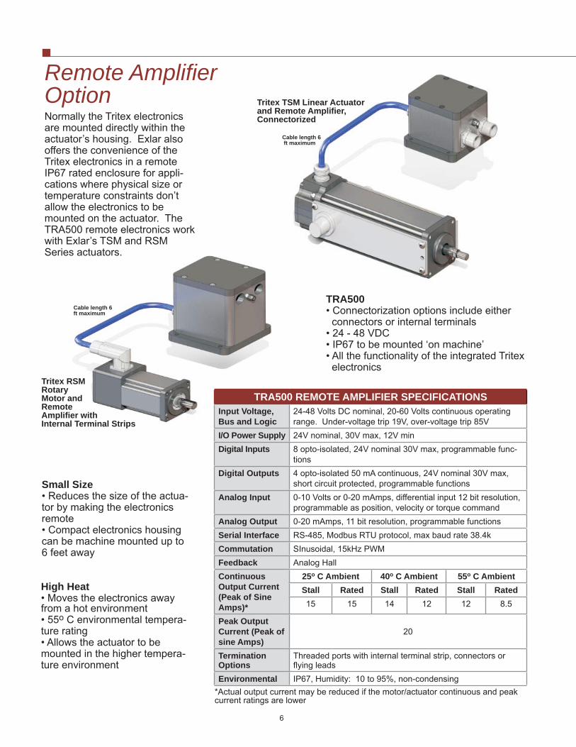
TLM30 Dimensions
25

TSM30 Dimensions (Requires TRA500 Remote Amplifi er)
26

RTM060 / RTG060 Dimensions
27

RSM060 / RSG060 Dimensions (Requries TRA500 Remote Amplifi er)
28

RTM090 / RTG090 Dimensions
29

RSM090 / RSG090 Dimensions (Requires TRA500 Remote Amplifi er)
30

31
TRA500 Remote Amplifi er and Rod End Attachment Dimensions
TRA500-I TRA500-N/G
TLM/TSM Rod Ends
Spherical Rod Eye
32
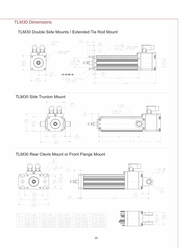
Rod End Attachment Dimensions (continued)

Model TTUSB485The TTUSB485 is a USB (Univer-sal Serial Bus) port to 2 or 4 wire isolated RS-485/422 converter. The serial port side can be set up for an RS-422 or RS-485 network. USB bus supplies power so no separate power supply is needed.
Model TT232485The Model TT232485 is a feature packed RS232 to RS-422/485 9-pin converter. The driver uses automatic SD (send data) or TS (handshake) control, or can be confi gured as always enabled for use in RS-422 systems.
Model TTPS1048Model TTPS1048 unregulated 48 VDC, 10A power supply.
Model TTSR1Shunt regulator dissipates ex-cess kinetic or potential energy to prevent amplifi er over-voltage shut down.
TRITEX TLM SERIES ORDERING GUIDEAAABB-CCDD-E-FG-HHH-HH - (XX..XX - #####)AAA = Actuator Type G = Rod EndTLM = Tritex Linear Actuator M = Male US Standard Thread A = Male MetricBB = Actuator Frame Size F = Female US Standard B = Female Metric20 = 2 inch (50 mm) X = Special (please specify)30 = 3 inch (75 mm) HHH-HH = Motor StatorCC = Stroke Length TLM2003 = 3 inch (75 mm) 1B8-50 = 1 Stack, 5000 rpm at 48 VDC, 2500 rpm at 24 VDC06 = 6 inch (150 mm) 2B8-34 = 2 Stack, 3400 rpm at 48 VDC, 1700 rpm at 24 VDC10 = 10 inch (250 mm) 3B8-25 = 3 Stack, 2500 rpm at 48 VDC, 1250 rpm at 24 VDC (1)12 = 12 inch (305 mm) TLM3018 = 18 inch (455 mm) (TLM30 only) 1B8-20 = 1 Stack, 2000 rpm at 48 VDC, 1000 rpm at 24 VDCDD = Lead (linear motion per screw revolution) 2B8-13 = 2 Stack, 1300 rpm at 48 VDC, 650 rpm at 24 VDC01 = 0.1 inch (2.54 mm) 3B8-10 = 3 Stack, 1000 rpm at 48 VDC, 500 rpm at 24 VDC (1)02 = 0.2 inch (5.08 mm) X..XX = Travel and Housing Options (Multiple Possible)04 = 0.4 inch (10.16 mm). (TLM20 only) Travel Options05 = 0.5 inch (12.7 mm) (TLM30 only) AR = External Anti-rotate L1/2/3 = External LImit SwitchesE = Connections PF = Preloaded Follower (2) RB = Rear Brake I = Exlar Std M23 style connector XT = Special Travel OptionsBxx = Embedded leads, xx = length in feet, 3 ft std Housing OptionsJxx = Emb. leads w/receptacle, std M23 style connector, xx = ft, 3 ft std
P5 = IP65 sealed housingSpecial Motor Options
X = Special (please specify) XL = Special LubricationF = Mounting XM = Special Motor OptionC = Rear Clevis D = Double Side Mount ##### = Part Number Desitnator for SpecialsE = Extended Tie Rod F = Front Flange Optional 5 digit assigned PN to designate unique model numbersS = Side Mount T = Side Trunnion M = Metric Extended Tie Rod X = Special
33
(1) Not available on 3 inch stroke(2) The dynamic load rating of zero backlash, preloaded screws is 63% of the dynamic load rating of the std non-preloaded screws. The calcu-lated travel life of a preloaded screw will be 25% of the calculated travel life of the same size and lead of a non-preloaded screw.
Options/Accessories
Model TT485SPRS485 Communications split-ter. Use to daisy-chain multiple Tritex actuators.

TRITEX TSM SERIES ORDERING GUIDE (Also See TRA500 Next Page)AAABB-CCDD-E-FG-HHH-HH - (XX..XX - #####)AAA = Actuator Type G = Rod EndTSM = Tritex Linear Actuator Used with TRA500 Remote Amplifi er
M = Male US Standard Thread A = Male Metric
BB = Actuator Frame Size F = Female US Standard B = Female Metric20 = 2 inch (50 mm) X = Special (please specify)30 = 3 inch (75 mm) HHH-HH = Motor StatorCC = Stroke Length TSM2003 = 3 inch (75 mm) 1B8-50 = 1 Stack, 5000 rpm at 48 VDC, 2500 rpm at 24 VDC06 = 6 inch (150 mm) 2B8-34 = 2 Stack, 3400 rpm at 48 VDC, 1700 rpm at 24 VDC10 = 10 inch (250 mm) 3B8-25 = 3 Stack, 2500 rpm at 48 VDC, 1250 rpm at 24 VDC (1)12 = 12 inch (305 mm) TSM3018 = 18 inch (455 mm) (TSM30 only) 1B8-20 = 1 Stack, 2000 rpm at 48 VDC, 1000 rpm at 24 VDCDD = Lead (linear motion per screw revolution) 2B8-13 = 2 Stack, 1300 rpm at 48 VDC, 650 rpm at 24 VDC01 = 0.1 inch (2.54 mm) 3B8-10 = 3 Stack, 1000 rpm at 48 VDC, 500 rpm at 24 VDC (1)02 = 0.2 inch (5.08 mm) X..XX = Travel and Housing Options (Multiple Possible)04 = 0.4 inch.(10.16 mm) (TSM20 only) Travel Options05 = 0.5 inch (12.7 mm) (TSM30 only) AR = External Anti-rotate L1/2/3 = External Limit SwitchesE = Connections PF = Preloaded Follower (2) RB = Rear BrakeI = Exlar Std M23 style connector XT = Special Travel OptionsJ3 = Emb. leads w/receptacle, std M23 style conn., 3 ft. J6 = Emb. leads w/receptacle, std M23 style conn., 6 ft.
Housing OptionsP5 = IP65 sealed housing
X = Special (please specify) Special Motor OptionsF = Mounting XL = Special LubricationC = Rear Clevis D = Double Side Mount XM = Special Motor Option E = Extended Tie Rod F = Front Flange ##### = Part Number Designator for SpecialsS = Side Mount T = Side Trunnion Optional 5 digit assigned PN to designate unique model numbersM = Metric Extended Tie Rod X = Special
TRITEX RTM/RTG SERIES ORDERING GUIDEAAABBB-CCC-D-E-FFF-FF- (XX...XX) - #####)AAA = Actuator Type E = Connector OptionsRTM = Tritex Rotary Motor I = Exlar Std M23 style connector RTG = Tritex Rotary Gearmotor Bxx = Embedded leads, xx = length in feet, 3 ft std BBB = Frame Size Jxx = Embedded leads w/recpt., M23 std, xx = length in ft, 3 ft std 060 = 60 mm X = Special (please specify)090 = 90 mm FFF-FF = Motor StatorsCCC = Gear Ratio RTM / RTG060Blank = RTM 1B8-50 = 1 Stack, 5000 rpm at 48 VDC, 2500 rpm at 24 VDCSingle Reduction Ratios Double Reduction Ratios 2B8-34 = 2 Stack, 3400 rpm at 48 VDC, 1700 rpm at 24 VDC004 = 4:1 016 = 16:1 020 = 20:1 3B8-25 = 3 Stack, 2500 rpm at 48 VDC, 1250 rpm at 24 VDC005 = 5:1 025 = 25:1 040 = 40:1 RTM / RTG090010 = 10:1 050 = 50:1 100 = 100:1 1B8-17 = 1 Stack, 1700 rpm at 48 VDC, 850 VDC at 24 VDCD = Shaft Type 2B8-10 = 2 Stack, 1000 rpm at 48 VDC, 500 VDC at 24 VDCK = Keyed 3B8-07 = 3 Stack, 700 rpm at 48 VDC, 350 VDC at 24 VDCR = Smooth/Round XX = Special OptionsX = Special Shaft XH = Special Housing Options XM = Special Motor Options
XL = Special Lubrication##### = Part Number Designator for SpecialsOptional 5 digit assigned PN to designate unique model number
(1) Not available on 3 inch stroke(2) The dynamic load rating of zero backlash, preloaded screws is 63% of the dynamic load rating of the std non-preloaded screws. The calcu-lated travel life of a preloaded screw will be 25% of the calculated travel life of the same size and lead of a non-preloaded screw.
34

TRITEX RSM/RSG SERIES ORDERING GUIDE (Also see TRA500 Below)AAABBB-CCC-D-E-FFF-FF- (XX...XX) - #####)AAA = Actuator Type E = Connector OptionsRSM = Tritex Rotary Motor Used with Remote Amplifi er I = Exlar Std M23 style connector RSG = Tritex Rotary Gearmotor Used with Remote Amp J3 or J6 = Embedded leads w/receptacle, M23, J3 = 3 ft, J6 = 6 ft BBB = Frame Size FFF-FF = Motor Stators060 = 60 mm RSM / RSG060090 = 90 mm 1B8-50 = 1 Stack, 5000 rpm at 48 VDC, 2500 rpm at 24 VDCCCC = Gear Ratio 2B8-34 = 2 Stack, 3400 rpm at 48 VDC, 1700 rpm at 24 VDCBlank = RSM 3B8-25 = 3 Stack, 2500 rpm at 48 VDC, 1250 rpm at 24 VDCSingle Reduction Ratios Double Reduction Ratios RSM / RSG090004 = 4:1 016 = 16:1 020 = 20:1 1B8-17 = 1 Stack, 1700 rpm at 48 VDC, 850 VDC at 24 VDC005 = 5:1 025 = 25:1 040 = 40:1 2B8-10 = 2 Stack, 1000 rpm at 48 VDC, 500 VDC at 24 VDC010 = 10:1 050 = 50:1 100 = 100:1 3B8-07 = 3 Stack, 700 rpm at 48 VDC, 350 VDC at 24 VDCD = Shaft Type XX = Special OptionsK = Keyed XH = Special Housing OptionsR = Smooth/Round XM = Special Motor OptionsX = Special Shaft XL = Special Lubrication
##### = Part Number Designator for Specials Optional 5 digit assigned PN to designate unique model number
TRITEX SERIES CABLES & ACCESSORIES Part NumberPower Cables, molded M23 style connector, 8 pin, xxx = Length in feet. Std lengths 15, 25, 50 feet CBL-TTIPC-SMI-xxxI/O Cables, molded M23 style connector, 19 pin, xxx = Length in feet. Std lengths 15, 25, 50 feet CBL-TTIOC-SMI-xxxCommunication Cable, PICO type connector, 4 pin, xxx = Length in feet. Std lengths 15, 25, 50 feet CBL-TTCOM-xxxCommunication Cable for use with TT485SP, xxx = Length in feet. Std lengths 15, 25, 50 feet CBL-TTDAS-xxxCable with connectors both ends from TRA to actuator, 3 or 6 feet CBL-TTUMB-00xUniversal Serial bus port to RS-485/422 converter TTUSB485RS-232 to RS-422/485 converter TT23248548 VDC, 10A power supply TTPS1048Shunt regulator TTSRIRS-485 Splitter TT485SP
TRITEX TRA500 REMOTE AMPLIFIER ORDERING GUIDEAAABBB-C-#####AAA = Amplifi er TypeAAA = TRA Remote Amplifi erBBB = Power500 = 500 WattsC = Connector OptionsN = 1/2 inch NPSM Threaded HolesG = PG Threaded HolesI = Exlar Standard M23 Style ConnectorBxx = Embedded Leads, 3 ft std,. xx = length in feetJxx = Embedded Leads w/M23 receptacle, 3 ft std., xx = length in feet##### = Part Number Designaor for SpecialsOptional 5 digit assigned PN to designate unique model number
35

The Company - Headquartered in subur-ban Minneapolis, Minnesota, Exlar serves a global customer base with an extensive standard product line and complete engi-neering support for custom actuator applica-tions.
Exlar supports a large network of sales representatives in North America. To fi nd your local dealer, visit our website at www.exlar.com or call our headquarters at 952-368-3434. For assistance outside North America, please contact Exlar direct or one of our worldwide partners listed below.
Exlar Corporation1470 Lake Drive West
Chanhassen, MN 55317
PH: 952-368-3434FAX: 952-368-4877
6/2008 10K
North AmericaExlar Corporation952-368-3434www.exlar.com
Australia/New ZealandApplied Automation, Ltd.61 7 3713 [email protected]
AustriaKML Technologie43 1 6415030 0www.kml.at
BelgiumATB Automation nv/sa.32 2 334 99 99www.atb-automation.be
BrazilQG Industrial LTDA11 4828 72 [email protected]
ChinaBeijing Reloh International Trade [email protected]
Step-Servo Co., [email protected]
JW Motion Controls (Shanghai) [email protected]
ColumbiaControl de Movimiento Ltda57 1 428 [email protected]
Czech RepublicTG Drives s.r.o.420 545 234 [email protected]
DenmarkDelta Elektronik A/S45 4371 [email protected]
Eastern EuropeTG Drives s.r.o.420 545 234 [email protected]
FinlandSKS Control Oy358 20 764 [email protected]
FranceTranstechnik SA33 3805 [email protected]
GermanyExlar GmbH49 6142 [email protected]
HollandMijnsbergen B.V.31 297 28 58 21www.mijnsbergen.nl
IndiaServo Controls91-831-2407501www.servocontrolsindia.com
IrelandPro2development, Ltd.353 65 683 [email protected] Transmission [email protected]
ItalyServotechnica, srl39 0362 492 1www.servotecnica.it
JapanJW Motion Controls [email protected]
LuxembourgATB Automation32 2 334 9999www.atb-automation.be
MexicoUrany S.A. de C.V.442-220-90 [email protected] Motion Control AS47 64 [email protected]
RussiaProautomatika, LLC7 495 739 36 [email protected]
Singapore I-Motion Pte. [email protected]
Servo Drive Technology Pte. Ltd.65 90701308servodrive@pacifi c.net.sg
South KoreaMacpion Corp., Ltd.82 32 623 [email protected]
SpainMecanica Moderna S.A.34 93 [email protected]
SwedenCabavo AB46 8 559 15 [email protected]
SwitzerlandServotronic SA41 22 794 93 26www.servotronic.ch
TaiwanMultitech Co., Ltd.886 [email protected]
United KingdomIntelligent Motion Control, Ltd44 1327 307600www.inmoco.com
VenezuelaDigimex Sistemas C.A.58 243 [email protected]