
A geometrically nonlinear finite-element model of the cat ...

Article citation info: Chajdi M, Adri A, El Bikri K, Benamar R. Linear and geometrically nonlinear free and forced vibrations of multi-cracked beams. Diagnostyka. 2019;20(1):111-125. https://doi.org/10.29354/diag/103125
111
DIAGNOSTYKA, 2019, Vol. 20, No. 1 ISSN 1641-6414
e-ISSN 2449-5220 DOI: 10.29354/diag/103125
LINEAR AND GEOMETRICALLY NONLINEAR FREE AND FORCED VIBRATIONS OF MULTI-CRACKED BEAMS
Mohcine CHAJDI 1, Ahmed ADRI 2, Khalid EL BIKRI 1, Rhali BENAMAR 3
1 Mohammed V University in Rabat, ENSET - Rabat, MSSM, B.P.6207, Rabat Instituts, Rabat, Morocco, [email protected], [email protected]
2 Hassan II University of Casablanca, EST - Casablanca, LMPGI, B.P.8012, Oasis Casablanca, Morocco, [email protected]
3 Mohammed V University in Rabat, EMI - Rabat, LERSIM, B.P.765, Agdal, Rabat, Morocco, [email protected]
Abstract
The linear and geometrically nonlinear free and forced vibrations of Euler-Bernoulli beams with multi-cracks are investigated using the crack equivalent rotational spring model and the beam transfer matrix method. The Newton Raphson solution of the transcendental frequency equation corresponding to the linear case leads to the cracked beam linear frequencies and mode shapes. Considering the nonlinear case, the beam transverse displacement is expanded as a series of the linear modes calculated before. Using the discretised
equation is obtained and solved using the so-called second formulation, developed previously for similar nonlinear structural dynamic problems, to obtain the multi-cracked beam backbone curves and the corresponding amplitude dependent nonlinear mode shapes. Considering the forced vibration case, the nonlinear frequency response functions obtained numerically near to the fundamental nonlinear mode using a single mode approach show the effects of the number of cracks, their locations and depths, and the level of the concentric harmonic force. The inverse problem is explored using the frequency contour plot method to identify crack parameters, such as the crack locations and depths. Satisfactory comparisons are made with previous analytical results.
Keywords: nonlinear vibrations; multi-crack; Euler Bernoulli beams; free and forced vibrations
1. INTRODUCTION
Understanding the linear and nonlinear dynamic
behaviour of mechanical systems or some of their structural components widely used in engineering (such as beams, plates and shells) is one of the main problems in structural design and is pervasive throughout the civil, mechanical and aerospace engineering communities. The designers who have to achieve acceptable levels of performance and economy, require efficient use of materials while ensuring the safety and durability of the structural components in order to avoid structural failures [1]. Due to various external or internal influences, such as moving vehicles in the case of steel bridges, winds for tall buildings, waves for offshore platforms and high temperatures for turbomachinery, defects may occur and sometimes dramatically reduce the resistance capacity or the structural fatigue life. Consequently, conventional analyses of the structural constraints may lead to inaccurate security conclusions if they ignore the cracks that are very often present [2]. Many studies have suggested that nearly 90% of failures in metal structures are primarily fatigue failures. Although because of its complex nature, the process of initiation and propagation of cracks is very silent
and quite difficult to understand [3], designers have no alternative but to ensure that all structural components have adequately known fatigue lives. The reader interested in more details on this subject can be returned to [4 6]. The nature of the fatigue process requires a field inspection to control the structural behaviour and detect and / or predict possible damages and ensure a correct evaluation of the residual load capacity. Also, the evolution of initiated fatigue cracks must be well controlled in order to avoid them to grow to the point of complete ruptures and catastrophic failures, inducing economical disasters and sometimes a loss of human lives, as has been reported in recent decades. It is well known that the presence of cracks, due to the induced local variations in the stiffness and damping characteristics, affect the dynamic characteristics of the whole structure to a considerable degree. They often occur in structural members during the operational life as a result of a reduced fatigue strength due to pre-existing flaws or high stress concentrations, or due to the application of repeated loads in a severe environment, or to the growth of cracks initiated inside the material during the manufacturing processes. The growth of fatigue cracks in structural components can be evaluated using data

DIAGNOSTYKA, Vol. 20, No. 1 (2019) Chajdi M, Adri A, EL Bikri K, Benamar R.: Linear and geometrically nonlinear free and forced vibrations of
112
collected during regular field inspections involving visual examination and / or use of a variety of non-destructive evaluation techniques. However, the visual inspection efficiency depends mainly on the inspector's experience and the type of damages observed, making the detection of cracks difficult by this method. As the presence of cracks must be detected at a very early stage for obvious safety reasons, recourse is often made to non-destructive detection methods based on the examination of the changes in the structural vibration characteristics. The basic idea behind such an approach is that the modal parameters, such as the natural frequencies, the mode shapes, and the modal damping are functions of the distribution through the structure of the mass, damping, and stiffness so that any change in these physical properties alter the dynamic response. These extracted physical parameter changes are used when possible to extract damage information, such as the position, the depth and the severity of the damages occurring in a structure without disengaging all of the system. Recently, long-term structural health surveillance and structural vibration analysis techniques have become among the main topics interesting researchers and engineers having in charge to maintain structural integrity. Much work is done to define efficient and simple procedures for non-destructive examination [7]. Two types of approaches related to this subject exist: the first, called (direct problem), consists on determination of the effect of a damage of a known type on the structural dynamic characteristics. Typically, the damage is modelled mathematically, and then the measured frequencies are compared to the predicted frequencies to determine the damage. This preliminary analysis is necessary to apply the second approach called (inverse problem) which consists on establishing various ways for identifying or predicting the crack locations and depths using measurements performed on the system. In the present work, the direct problem is mainly examined in order to provide workers in the field with useful data for crack analysis, in both the linear and nonlinear regimes. The inverse problem is also approached using the so-called frequency contour plot method, considered as one of the most favoured tools, used previously in [8,9], and more recently in [10] to identify crack parameters such as the crack location and depth using the lowest three natural frequencies based on linear analysis. As the vibration analysis of cracked beams is the basis of most structural health surveillance techniques, it has received a great deal of attention in the recent decades. As a result, a variety of analytical, numerical and experimental investigations now exist [11 13]. Adams et al studied the specification of the crack location in a beam structural element by modelling an axial crack by a longitudinal spring without calculating the spring stiffness [14]. However, the general practice in the application of a crack model to a structural damage detection
problem requires to establish first a relationship between the crack parameters and the structure characteristics. This relationship is often taken as a frequency equation of the cracked beam. Consequently, various crack models proposed later by many researchers attempted to describe the effect of cracks on the dynamic behaviour of beams. Three types of crack models may be mentioned: the model based on a local stiffness reduction [15,16], the spring models [17] and the finite element models [18,19]. In the analytical models based on a beam element, the crack is treated as a local change in rigidity or flexibility at the cross section of the crack site. Dimarogonas suggested in his pioneering work [20] an attractive method, called the transverse crack model, for modelling an open edge crack in the case of pure bending beam vibrations using an equivalent rotational spring connecting the two sides of a beam at the crack position. The spring stiffness was derived from the stress intensity factors using the theory of fracture mechanics. Under the most general load, the local flexibility is presented by a matrix whose coefficients depend on the crack size and geometry [21]. This crack model was validated via a comparison with different models in [22], demonstrating the adequacy of this latter simple model of the crack flexibility based on beam elements. Recently, the singularity flexural stiffness model, based on the Dirac delta method [23], has been found to be equivalent to an internal hinge with a rotating spring. This motivated dynamic analyses of cracked structures using the shifts in natural frequencies to detect the crack sizes and locations. In recent years, increased attention has been given to solve the direct problem for vibrating beams in the presence of local cracks. In general, two main types of methods are adopted for studying the dynamic behaviour of cracked beams, continuous and discrete methods. In continuous methods, such as the one used here, a beam is divided into a number of sub-beams connected by rotating springs at the crack locations and the transverse beam vibration equation is solved at each interval with appropriate continuity and end conditions. Discrete techniques involve use of the finite element method [24]. Most of the works available, using the continuous method, correspond to a structure with a single transverse surface with several approaches to determine the natural frequency changes [25 30]. The dynamic behaviour of a double-cracked beam and a rotor with two cracks has been also investigated in [31 36]. In all of the above studies, the analysis of the effect of cracks on the beam dynamic properties was performed using a common approach based on a sub-division of the beam into a number of sub-beams or sub-segments, separated at a crack location and connected by rotational springs, with different modal displacement functions used for each sub-beam. The transverse vibration of an Euler Bernoulli beam is governed by a fourth order

DIAGNOSTYKA, Vol. 20, No. 1 (2019) Chajdi M, Adri A, EL Bikri K, Benamar R.: Linear and geometrically nonlinear free and forced vibrations of
113
partial differential equation requiring, after variables separation, four coefficients for the modal transverse displacement function for each sub-beam. The four beam end conditions, in addition to four continuity conditions at each crack location lead to a homogeneous system whose determinant must vanish in order to permit non-trivial solutions to exist. Equating the determinant to zero leads to the frequency equation of the cracked beam. Theoretically, this approach can be extended to more than one crack and end conditions, leading to an increase in the order of the characteristic determinant to 4(n+1) for a beam with n cracks. Shifrin and Ruotolo proposed in [37] an algebraic technique for reducing the order of the determinant for a beam with n cracks from 4(n+1) to (n+2). Recently, Khiem and Lien proposed in [38] a more simplified method based on the transfer matrix procedure for evaluating the natural frequencies of beams with an arbitrary number of cracks and reduced the order of the determinant to 4 by relating the variables at the end of each sub-beam with those of the beam first end. Later, the methods proposed in [37,38] were extended by [39] to the evaluation of the longitudinal natural frequencies of vibrating bars with an arbitrary number of cracks. Li, proposed in [40] an approach using a properly derived basic solution, exploiting the fundamental solutions for each sub-beam, and obtained the natural frequencies by solving a second-order determinant. Binici proposed in [41] an extension of the procedure presented in [40] to the case of beams with multiple cracks in the presence of an axial force by selecting the appropriate fundamental solutions. Using recurrence formulae, the eigen-value equation was obtained by evaluating a second-order determinant in terms of initial parameters satisfying the end conditions and the corresponding mode shapes. Few researchers have studied the axial load effect on the vibration and stability of cracked beams [42,43]. A state of the art concerning this topic can be found in [44] with particular references. In the studies mentioned above, only linear vibrations of cracked beams are investigated and the studies including the non-linear effects are rather rare. In the literature, cracks are considered to be always open or supposed to be breathing in time. The nonlinear effect due to a breathing or switching crack i.e. cracks that are either fully open or fully closed, on the flexural vibration of cracked structures has been discussed in some papers [45 48]. The results obtained showed that the difference of solutions between the open and breathing crack models is quite small when the amplitude is not very large, and the difference becomes significant as the amplitude increases. Consequently, most researchers assume in their models that the cracks remain open. If the effects of large vibration amplitudes cannot be ignored, another type of nonlinearity has to be examined. Indeed, the health monitoring is more strongly required when the structures work in
severe environments and are subjected to high strains and stresses, making it necessary to include the effects of geometrical non-linearity in the vibration analysis. The treatment of this case is complicated because it combines the domains of geometrically nonlinear analysis and the fracture
very few previous works modelling the geometrically nonlinear vibrations of multi-cracked structures. There have been several attempts to mathematically describe the nonlinear structural dynamic behaviour but this topic still appears a little difficult to handle in practical situations. Benamar and co-workers have successfully described the problem of geometrically nonlinear free and forced vibrations of various types of thin straight structures [49 52] principle and spectral analysis and showing that the concept of normal linear modes of vibration remains very useful for expanding the unknown displacement series in the nonlinear case. This has been demonstrated theoretically by the relative mathematical simplicity of the nonlinear semi-analytical models developed. El Bikri et al investigated the free and forced vibrations of beams with one edge crack [53]. The objective of the present paper is to present an analytical method to analyse the linear and geometrically nonlinear free and forced vibrations of Euler Bernoulli beams with multi-cracks, located at different positions. The cracked beam is modelled as an assembly of uniform sub-segments connected by massless rotational springs presenting the reduced local flexibility due to an open non-propagating edge crack. The flexibilities of these springs are calculated using the fracture mechanics theory. Based on the Euler Bernoulli beam theory, the differential equations are solved at each segment. Four unknown coefficients appear in the solution for the deflection function at each sub-segment of the cracked beam. To determine these constants, the transfer matrix method previously used in [54] is employed to satisfy the conditions at the extremities of each sub-segments, which leads to a linear frequency equation for the damaged beam solved iteratively using the Newton Raphson method. This equation is expressed in terms of the elements of the overall transfer matrix. In addition, the linear mode shapes of the damaged beam play a crucial role because of their use as trial functions in the nonlinear analysis. The crack identification problem has been also studied and validated using the frequency contour plot method in the case of a single crack. The nonlinear case is then developed using a semi analytical method and the model developed previously in [50]. The nonlinear beam transverse displacement function is defined as a linear combination of the linear modes. The discretized expressions for the total strain and kinetic energies of the beam are then derived, and
reduced to a nonlinear algebraic system which is

DIAGNOSTYKA, Vol. 20, No. 1 (2019) Chajdi M, Adri A, EL Bikri K, Benamar R.: Linear and geometrically nonlinear free and forced vibrations of
114
solved using the so-called second formulation developed previously in [55] leading to the basic function contribution coefficients to the displacement response function of the multi-cracked beam and to the corresponding backbone curve i.e. the amplitude-frequency and mode shapes dependence. The nonlinear forced case also examined by using a single mode approach as in [56], to obtain the nonlinear frequency response curves in the neighbourhood of the predominant nonlinear mode shape, A parametric study and detailed numerical results are given to demonstrate the effectiveness of the proposed procedure. The calculated frequencies and the corresponding mode shapes are expected to be useful to evaluate the influence of parameters like the number of cracks, the crack locations and depths, the vibration amplitude, and the level of the applied harmonic force, on the beam dynamic response.
2. LINEAR VIBRATIONS OF A MULTI-
CRACKED BEAM
Before examining the nonlinear vibrations of a multi-cracked beam, we start by determination of its linear frequencies and mode shapes, in order to use them as basic functions in the nonlinear theory. The spring crack model and the transfer matrix method are used, leading to calculation of a 4×4 matrix. The steel uniform beam shown in Fig. 1, supported by linear and rotational springs at both ends, is examined in the present work. It contains N cracks of different depths located at different positions. The beam material and geometrical properties are: E=200GPa, material density =7860Kg/m3, thickness h=0.1m, width b=0.1m, and length L=10m. x is the coordinate along the neutral axis of the beam measured from the right end, xj is the coordinate of the crack position and w(x,t) is the transverse deflection of the beam measured from its equilibrium position.
2.1. Free vibrations The free vibrations of the cracked beam
described above is governed by the following differential equation:
4
44 0d w w
dx (1)
The transverse displacement function w of the beam with ( *x x L and j jx L ) is defined in piecewise by:
*1 1
* *1
1*
0,
...
,
...
,1
j j j
N N
w x
w x w x
w x
(2)
A closed form solution to this eigenvalue problem can be obtained by employing the transfer matrix method presented in [54]. The general solution for transverse vibrations in the jth span can be written as:
* *-1
* *-1 -1
*-1
cosh -
sinh - cos -
sin -
ji j i j
j i j j i j
j i j
w x A L x
B L x C L x
D L x
(3)
*1j jx for j N+1
In which:
2
4 ii
SEI
(4)
for i=1 to n, are the beam eigenvalue parameters. The constants (Aj, Bj, Cj and Dj) are determined by the beam end and continuity conditions at the crack locations as follows:
At the left end
L
1K
1tK
2K
2tK
2x
1x
1jxjx
1jx
1w2w 1jw jw 1jw 1Nw
Fig. 1. Physical model of a beam with multiple edge open cracks supported by linear and rotational
springs at both ends

DIAGNOSTYKA, Vol. 20, No. 1 (2019) Chajdi M, Adri A, EL Bikri K, Benamar R.: Linear and geometrically nonlinear free and forced vibrations of
115
*
*
* *
3 **1
1 1*3 00
2 * *1 1
1*2 *0 0
it i
xx
i i
x x
d w x K w xdx
d w x dw xK
dx dx
(5)
At the right end
*
*
* *
3 **(N 1)
2 (N 1)*3 11
2 * *(N 1) (N 1)
2*2 *1 1
it i
xx
i i
x x
d w x K w xdx
d w x dw xK
dx dx
(6)
Kt1, Kt2, K and K are the stiffness of the transverse and rotational springs at the left and right ends of the beam respectively.
2.2. Modelling of a crack in a beam under a
bending moment The continuity and compatibility equations of
the beam at the jth crack position j are:
Continuity of the displacement **1
jjj i ji xx
w w (7)
Continuity of the flexural moment
**
2 21
*2 *2
jj
j i ji
xx
d w d wdx dx
(8)
Continuity of the shear force
**
3 31
*3 *3
jj
j i ji
xx
d w d wdx dx
(9)
The compatibility condition
* **
21
* * * *2
j jj
j i ji ji
x xx
dw dw d wLdx dx K dx
(10)
Where *K is the non-dimensional local rigidity due to the crack, related to the local flexibility coefficient C of the rotational springs, expressed as [53]:
* K LLKCEI EI
(11)
K being the torsional stiffness of the open crack
21
72
bh EKC F
h
(12)
With:
2
0h f d
h h h hF (13)
Where h is the crack depth and f h is called the crack correction function given by [57]:
4
0.923 0.199 1 sin22
2 cos2
hhf h tgh
h
(14)
2.3. Transfer matrix The constants (Aj+1, Bj+1, Cj+1 and Dj+1) in the
(j+1)th span are related to those in the jth span (Aj, Bj, Cj and Dj) through the continuity and compatibility conditions. They can be expressed by:
1 11 12 13 14
1
1
1 41 44
. . . .
. . . .. .
j j j jj j j
j j jj
j j jj j
j j j
A A At t t tB B B
TC C CD D Dt t
(15)
Where Tj is a 4×4 transfer matrix which depends on i . The general terms of Tj are:
111
112
13
14
cosh
sinh
0
0
jj ji
jj ji
j
j
t L
t L
t
t
(16)
121
1*
122
1*
123 *
124 *
sinh
1 cosh2
cosh
1 sinh2
1 cos21 sin2
jj j
j jik
jj j
j jik
jj ji
k
jj ji i
k
i
i
i
i
i
t L
L L LK
t L
L L LK
Lt L LKLt L L
K
(17)
31
32
33 1
34 1
0
0
cos
sin
j
j
ji j j
ji j j
t
t
t L
t L
(18)
41 1*
42 1*
43 1
1*
44 1
1*
1 cosh21 sinh2
sin
1 cos2
cos
1 sin2
ji i j j
k
ji i j j
k
ji j j
i i j jk
ji j j
i i j jk
Lt L LKLt L L
K
t L
L L LK
t L
L L LK
(19)
Through repeated applications of Eq. (15), the four constants in the first segment (Aj, Bj, Cj and Dj) can be mapped into those of the last segment,

DIAGNOSTYKA, Vol. 20, No. 1 (2019) Chajdi M, Adri A, EL Bikri K, Benamar R.: Linear and geometrically nonlinear free and forced vibrations of
116
reducing the total number of independent constants to four.
1
12 1
1
1
1
1
1
1
...N
N
N
N
N
A AB B
T T TC CD D
(20)
These four remaining constants (A1, B1, C1 and D1) can be found through the satisfaction of the end conditions, i.e Eq (6) leading to:
3N 1 1 2 1
3N 1 1 2 1
3N 1 1 2 1
3N 1 1 2 1
( ) sinh cosh
( ) cosh sinh
( ) sin cos
( ) cos sin 0
i i j j t i j j
i i j j t i j j
i i j j t i j j
i i j j t i j j
A L L K L
B L L K L
C L L K L
D L L K L
(21)
1 2 1N 1
N 1 1 2 1
N 1 1 2 1
N 1 1 2 1
cosh sinh
sinh cosh
cos sin
sin cos 0
i i j j i j j
i i j j i j j
i i j j i j j
i i j j i j j
A L L K L
B L L K L
C L L K L
D L L K L
(22) Equations (21) and (22) can be expressed in a matrix form:
11 211 1
12 221 1
13 231 1
14 241 1
00
TN N
N N
N N
N N
A AB BB BB B
BC CB BD DB B
(23)
Such as: 3
11 1 2 1
312 1 2 1
313 1 2 1
314 1 2 1
( ) sinh cosh
( ) cosh sinh
( ) sin cos
( ) cos sin
i i j j t i j j
i i j j t i j j
i i j j t i j j
i i j j t i j j
B L L K L
B L L K L
B L L K L
B L L K L
(24)
1 2 1
1 2 1
1 2 1
1 2 1
21
22
23
24
cosh sinh
sinh cosh
cos sin
sin cos
j j j j
j j j j
j j j j
j j j j
i i i
i i i
i i i
i i i
B L L K L
B L L K L
B L L K L
B L L K L
(25) Substitution of Eq. (23) into Eq. (20) leads to:
11
112 1
11
11
0...
0N
N
N
N
N
A AB B
B B T T TC CD D
(26)
And Eq. (5) lead to:
3 3
1 1 1 1 1 1
1 1 1 1 1 1
00
t i t i
i i
K A B L K C D LA L B K C L D K
(27)
Which can be expressed in a matrix form as:
1 1 13
1 1 1
1 1 13
1 1 1
( )
( )
Tt i
i
t i
i
K L A AL K B B
RK L C C
L K D D
(28)
Such as:
3 3
1 1
1 1
( ) ( )t ti i
i i
K KL LR
L LK K (29)
Equations (28) and (26) lead to:
1 1
2 1 1 1
1 1
1 1
0... 0
00
N
A ABT T T B B
YR C C
D D
(30)
Where
2 1...NBT T TY
R (31)
For the existence of a non-zero solution of the homogeneous system (31), the determinant of matrix Y must be stated equal to zero, leading to the following parametric equation *( , , ) 0g K .
det 0Y Y (32) Equation (32) has been solved using the
Newton Raphson algorithm to find the natural frequencies. The corresponding mode shapes have been then calculated by the usual algebraic procedure.
2.4. Numerical results and discussions
In order to perform the numerical calculations, a computer program has been written using Matlab Software. Through this program, it became possible to analyse the effects of the number, the positions and the magnitudes of the cracks upon the vibration frequencies and modes shapes of beams. To test the validity and accuracy of the present analysis, the values of the vibration frequencies for the first six vibration modes have been calculated and compared with available data [58]. In Table.1, corresponding to fully clamped beams with triple cracks, having the following properties: Length L=1.4m, width b=0.01m, depth h=0.09m, mass density =7855kg/m3 E=200×109 N/m2. For three cracks positioned at
1=0.2, 2=0.45 and 3=0.7, the clamped ends are obtained by taking Kt1=Kt2=K =K = , the results show an excellent agreement of the present study with those of [58] since the relative difference does not exceed 0.01% for all of the cases considered. Additionally, the relative difference seems to increase linearly by increasing the crack magnitude. Figure 2 gives the ratios of the first three natural frequencies of a beam with a single crack to the corresponding frequencies of the uncracked beam, versus the normalized crack position and depth
, for clamped beam end conditions. It can be noticed that if a crack is located at a node of a given mode, it does not affect its corresponding frequency

DIAGNOSTYKA, Vol. 20, No. 1 (2019) Chajdi M, Adri A, EL Bikri K, Benamar R.: Linear and geometrically nonlinear free and forced vibrations of
117
but it affects predominately the modes whose venters are close to the crack location. It appears also that the natural frequencies of a cracked beam are influenced, as may be expected, by both the crack position and the crack depth.
Using the parameters i, for i = 1 to 10, the linear modes, used below in the nonlinear analysis as basic functions, are plotted in Fig. 3, showing the normalized (a) symmetrical and (b) anti-symmetrical linear mode shapes of a clamped beam containing five equally distributed cracks with a depth of =0.3.
Fig. 3. (a) Symmetrical and (b) Anti-
symmetrical mode shapes of clamped beam with five cracks corresponding to k/h=0.3
Fig. 2. Effect of the crack on the first three natural frequencies of the beam.
Table 1. Comparison of the first six modal frequencies of a clamped beam with three cracks.
Crack scenarios Method Modes
Crack depth ratio 1 2 3 4 5 6
(10-10-10) %
Present 43.1244 118.8202 232.8127 385.0869 575.1024 803.3228
(a) 43.1323 118.8541 232.9065 385.1886 575.2884 803.5648 (b) 43.1400 118.8700 232.9300 385.2000 575.3800 803.7000 (c) 43.1323 118.8522 232.9047 385.1858 575.2675 803.5540
Rel. diff. % 0.0002 0.0003 0.0004 0.0003 0.0004 0.0004
(30-30-30) %
Present 42.8548 117.6658 229.5800 381.7393 568.8926 795.1535 (a) 42.9247 117.9643 230.4249 382.5813 570.4717 797.2471 (b) 42.9200 117.9300 230.3600 382.4100 570.2200 769.9900 (c) 42.9198 117.8232 230.2858 382.3678 568.8627 796.4205
Rel. diff. % 0.0016 0.0020 0.0034 0.0019 0.0017 -0.0092
(50-50-50) %
Present 42.1218 114.5653 220.7699 378.5744 553.4903 774.1506 (a) 42.3618 115.5740 223.6569 376.2644 558.3072 780.8314 (b) 42.3000 115.2700 222.9000 374.3400 555.4700 777.8700 (c) 42.3028 113.7744 221.8603 373.7671 537.6546 770.4146
Rel. diff. % 0.0047 0.0027 0.0091 0.0101 0.0055 0.0029 (a)Solution of the characteristic equation [58]; (b)measurement [58]; (c)calculated by the Rayleigh [58]. *100 × |Average [(a), (b), (c)] Present| / |Average [(a), (b), (c)]|.
DIAGNOSTYKA, Vol. 20, No. 1 (2019) Chajdi M, Adri A, EL Bikri K, Benamar R.: Linear and geometrically nonlinear free and forced vibrations of
118
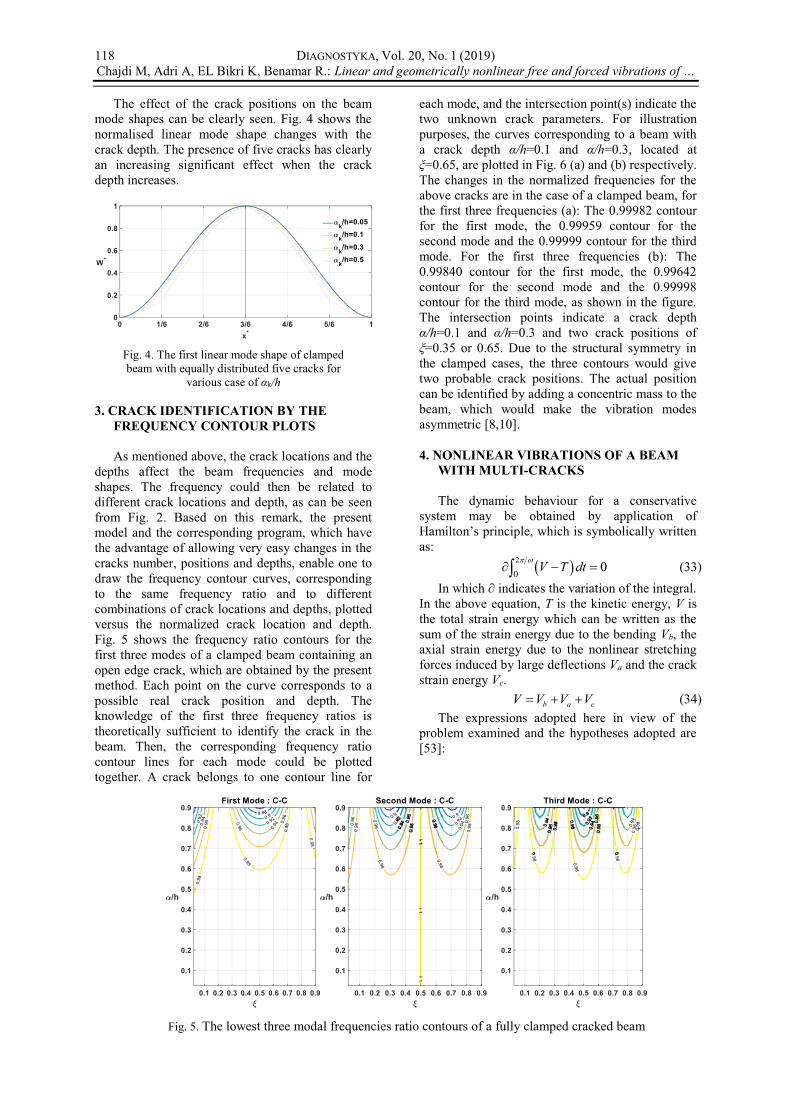
The effect of the crack positions on the beam mode shapes can be clearly seen. Fig. 4 shows the normalised linear mode shape changes with the crack depth. The presence of five cracks has clearly an increasing significant effect when the crack depth increases.
Fig. 4. The first linear mode shape of clamped beam with equally distributed five cracks for
various case of k/h 3. CRACK IDENTIFICATION BY THE
FREQUENCY CONTOUR PLOTS
As mentioned above, the crack locations and the depths affect the beam frequencies and mode shapes. The frequency could then be related to different crack locations and depth, as can be seen from Fig. 2. Based on this remark, the present model and the corresponding program, which have the advantage of allowing very easy changes in the cracks number, positions and depths, enable one to draw the frequency contour curves, corresponding to the same frequency ratio and to different combinations of crack locations and depths, plotted versus the normalized crack location and depth. Fig. 5 shows the frequency ratio contours for the first three modes of a clamped beam containing an open edge crack, which are obtained by the present method. Each point on the curve corresponds to a possible real crack position and depth. The knowledge of the first three frequency ratios is theoretically sufficient to identify the crack in the beam. Then, the corresponding frequency ratio contour lines for each mode could be plotted together. A crack belongs to one contour line for
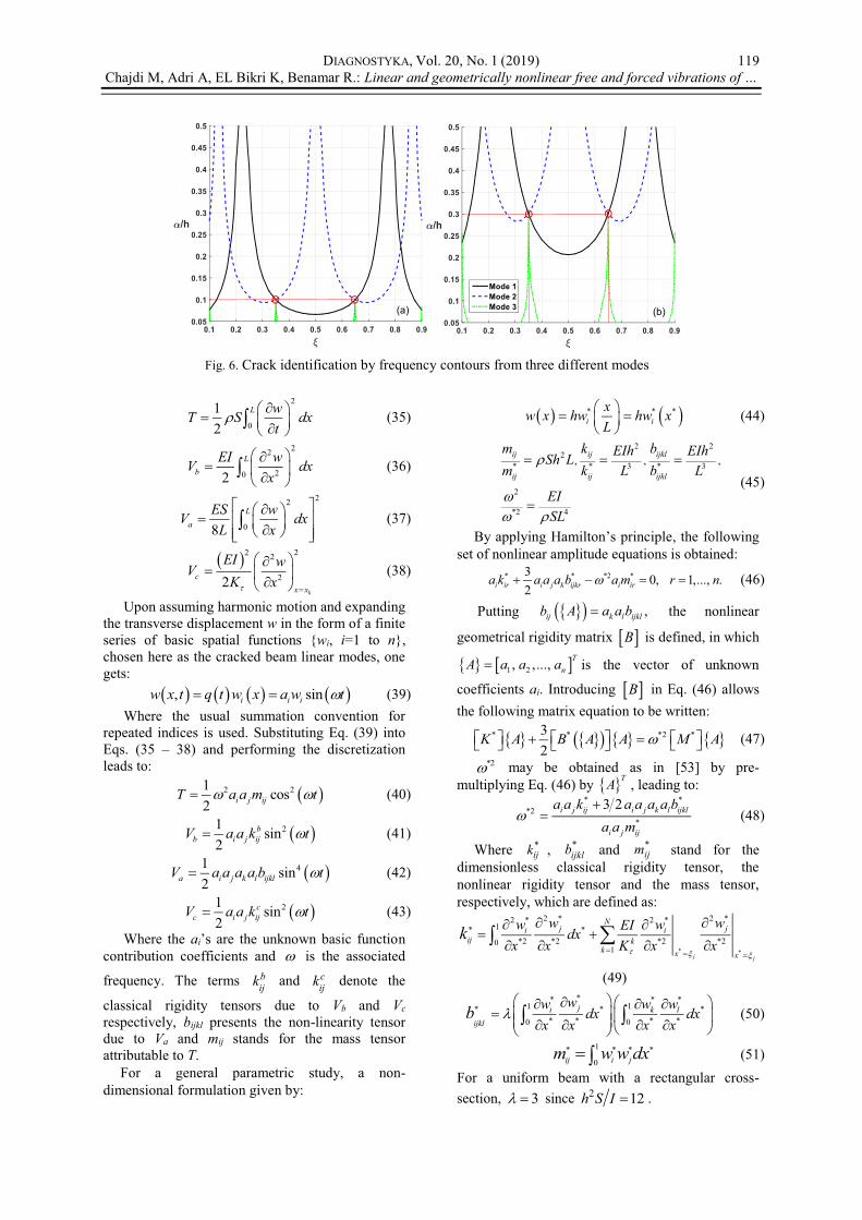
each mode, and the intersection point(s) indicate the two unknown crack parameters. For illustration purposes, the curves corresponding to a beam with a crack depth =0.1 and =0.3, located at =0.65, are plotted in Fig. 6 (a) and (b) respectively.
The changes in the normalized frequencies for the above cracks are in the case of a clamped beam, for the first three frequencies (a): The 0.99982 contour for the first mode, the 0.99959 contour for the second mode and the 0.99999 contour for the third mode. For the first three frequencies (b): The 0.99840 contour for the first mode, the 0.99642 contour for the second mode and the 0.99998 contour for the third mode, as shown in the figure. The intersection points indicate a crack depth
=0.1 and =0.3 and two crack positions of =0.35 or 0.65. Due to the structural symmetry in
the clamped cases, the three contours would give two probable crack positions. The actual position can be identified by adding a concentric mass to the beam, which would make the vibration modes asymmetric [8,10].
4. NONLINEAR VIBRATIONS OF A BEAM
WITH MULTI-CRACKS
The dynamic behaviour for a conservative system may be obtained by application of
as:
2
0 0V T dt (33) In which indicates the variation of the integral.
In the above equation, T is the kinetic energy, V is the total strain energy which can be written as the sum of the strain energy due to the bending Vb, the axial strain energy due to the nonlinear stretching forces induced by large deflections Va and the crack strain energy Vc. b a cV V V V (34)
The expressions adopted here in view of the problem examined and the hypotheses adopted are [53]:
Fig. 5. The lowest three modal frequencies ratio contours of a fully clamped cracked beam
DIAGNOSTYKA, Vol. 20, No. 1 (2019) Chajdi M, Adri A, EL Bikri K, Benamar R.: Linear and geometrically nonlinear free and forced vibrations of
119
2
0
12
L wT S dxt
(35)
22
202L
bEI wV dx
x (36)
22
08L
aES wV dx
L x (37)
22 2
22k
cx x
EI wVK x
(38)
Upon assuming harmonic motion and expanding the transverse displacement w in the form of a finite series of basic spatial functions {wi, i=1 to n}, chosen here as the cracked beam linear modes, one gets: , sini i iw x t q t w x a w t (39)
Where the usual summation convention for repeated indices is used. Substituting Eq. (39) into Eqs. (35 38) and performing the discretization leads to:
2 21 cos2 i j ijT a a m t (40)
21 sin2
bb i j ijV a a k t (41)
41 sin2a i j k l ijklV a a a a b t (42)
21 sin2
cc i j ijV a a k t (43)
Where the ai n contribution coefficients and is the associated
frequency. The terms bijk and c
ijk denote the
classical rigidity tensors due to Vb and Vc respectively, bijkl presents the non-linearity tensor due to Va and mij stands for the mass tensor attributable to T.
For a general parametric study, a non-dimensional formulation given by:
* * *i i
xw x hw hw xL
(44)
2 22
* * 3 * 3
2
*2 4
, , ,ij ij ijkl
ij ij ijkl
m k bEIh EIhSh Lm k L b L
EISL
(45)
By a , the following set of nonlinear amplitude equations is obtained:
* * *2 *3 0, 1,..., .2i ir i j k ijkr i ira k a a a b a m r n (46)
Putting ,ij k l ijklb A a a b the nonlinear
geometrical rigidity matrix B is defined, in which
1 2, ,..., TnA a a a is the vector of unknown
coefficients ai. Introducing B in Eq. (46) allows the following matrix equation to be written:
* * *2 *32
K A B A A M A (47) *2 may be obtained as in [53] by pre-
multiplying Eq. (46) by TA , leading to:
* *
*2*
3 2i j ij i j k l ijkl
i j ij
a a k a a a a ba a m
(48)
Where *ijk , *
ijklb and *ijm stand for the
dimensionless classical rigidity tensor, the nonlinear rigidity tensor and the mass tensor, respectively, which are defined as:
* *
2 * 2 *2 * 2 *1* *
*2 *2 *2 *201
j j
Nj ji i
ij kk x x
w ww wEIdxx x K x x
k
(49)
** * *
1 1* * ** * * *0 0
ji k lijkl
ww w wdx dx
x x x xb (50)
1* * * *0ij i jm w w dx (51)
For a uniform beam with a rectangular cross-section, 3 since 2 12h S I .
Fig. 6. Crack identification by frequency contours from three different modes

DIAGNOSTYKA, Vol. 20, No. 1 (2019) Chajdi M, Adri A, EL Bikri K, Benamar R.: Linear and geometrically nonlinear free and forced vibrations of
120
Finally, by Substituting Eq. (48) into Eq. (46) one can obtain the following nonlinear algebraic system
* *
* **
*
32
3 20
i ir i j k ijkr
i j ij i j k l ijkli ir
i j ij
a k a a a b
a a k a a a a ba m
a a m
(52)
Equation (52) is identical to that obtained in [53] for the nonlinear free vibrations of beams using Hamilton's principle and integrating the time functions over the range 0,2 . These equations are a set of nonlinear algebraic equations, involving the parameters *
ijm , *ijk and *
ijklb which are the range [0,1]. In order to obtain the numerical solution for the nonlinear problem in the neighbourhood of a given mode, the contribution of this mode is chosen and those of the other modes are calculated numerically using the iterative method used in [53] or explicitly with the so-called second formulation [55] presented below.
4.1. Brief review of the second formulation
To obtain the beam nonlinear mode shapes and resonance frequencies at large vibration amplitudes the set of nonlinear algebraic Eq. (52) may be solved using the second formulation presented in [55]. The basic idea behind this formulation consists on writing the contribution vector to the nonlinear mode considered as 1 3 11, ,...,A a to indicate that 1a is the predominant contribution.
Then, considering the expression *i j k ijkra a a b of Eq.
(52), third and second order terms with respect to i , i.e. terms of type i j k ijklb and of the type
1 1i j ij ra b are neglected. This leads to:
* 3 * 2 *1 111 1 11i j k ijkr r i ira a a b a b a b (53)
Substituting and rearranging permits one to write Eq. (46) in matrix form as:
* *2 * *
3 *1 111
32
32
RI RI RI I RI
i
K M A A
a b (54)
Where the matrices * *RI ijK k and
* *RI ijM m , associated with the first nonlinear
mode, are obtained by varying i and j in the set (3, *I depends on ai, with a general term
*ij equal to 2 *
1 11ija b . The reduced unknown vector
3 5 11, ,...,TRIA presents the modal
contributions that can be obtained very easily by solving the linear system (54) of five equations and five unknowns. The same procedure can be applied to get the other nonlinear cracked beam mode shapes.
4.2. Numerical results and discussions
Before considering in this section the beam shown in Fig. 1, with five evenly distributed cracks, and in order to test the accuracy of the procedure of solution used, i.e. the second formulation mentioned above, a comparison is made in Tables 2-3 between results obtained here and the results reported in [53], based on an iterative solution, corresponding to a beam with a single crack at the middle. In Table. 2, the first nonlinear mode shape of a clamped cracked beam is presented, with a1 varying from 0.05 to 0.6 and
=0.1. In Table. 3, the nonlinear frequency parameters obtained here from nonlinear analysis at very small vibration amplitudes, corresponding to the assigned contribution (b) a1=0.005 and (c) a1=0.05, are compared to those based on linear
Table 2. First nonlinear mode shape of a clamped beam with an edge crack at the center obtained with six symmetric basic functions.
1a maxw * *nl l
0.1
Present [53] Rel Diff % Present [53] Rel Diff %
0.05 0,079403 0,079576 0,22 1,00114 1,00054 0,06
0.3 0,475178 0,476171 0,21 1,040223 1,039429 0,08
0.6 0,943616 0,945722 0,22 1,152496 1,148448 0,35
Table 3. Comparison of dimensionless frequency parameters for different crack depths: (a) linear results, (b) (c)
nonlinear results
0.1 0.3 0.5
Present [53] Rel Diff % Present [53] Rel Diff % Present [53] Rel Diff %
(a) *l 22.3900 22.3080 0.366 21.8332 21.9363 0.472 20.6099 20.9936 1.86
(b) *nl 22.3904 22.3082 0.367 21.8356 21.9366 0.463 20.6304 20.9939 1.76
(c) *nl 22.4280 22.3335 0.421 21.8733 21.9628 0.409 20.6692 21.0232 1.71
Rel Diff = 100*|Present - [53]| / Present

DIAGNOSTYKA, Vol. 20, No. 1 (2019) Chajdi M, Adri A, EL Bikri K, Benamar R.: Linear and geometrically nonlinear free and forced vibrations of
121
analysis (a), for various crack depths. A reasonably good agreement is found in all cases showing that the nonlinear model tends to the linear theory at small vibration amplitudes [53].
Fig. 7. Backbone curves of a clamped beam with five cracks, in the vicinity of the first
mode, for various crack depths
The effect of the crack depth and the vibration amplitude on the nonlinear behaviour appears clearly in Fig. 7 giving the backbone curves associated to the first nonlinear mode shape of a clamped beam with equally distributed five cracks and different crack depth values. As mentioned in [53], it is seen that increasing the crack depth leads to an increasing in the frequency ratio due to the fact that the linear frequency, which is at the denominator, decreases with increasing the crack depth (Table. 2).
Fig. 8. The normalized first nonlinear mode shape of a clamped beam with five cracks,
corresponding to various vibration amplitudes and k/h=0.3
Fig. 9. The curvature distribution associated to the nonlinear deflection response function
of a clamped beam with five edge cracks, corresponding to various vibration amplitudes
and k/h=0.3.
The corresponding normalized nonlinear fundamental modes and associated curvatures
distributions obtained via the present model for various values of the maximum non-dimensional amplitude are plotted in Figures 8 and 9 respectively for a relative crack depth equal to
/h=0.3, showing the mode shape amplitude dependence of the clamped beam with five edge cracks with an increase of curvatures near to the clamped ends. This may lead one to expect that the flexural stresses will increase non-linearly near to the clamped end with the increase of the vibration amplitude. Consequently, the geometrically nonlinear theory presented here shows that is can be inaccurate to use frequency and stress data obtained by linear theory.
5. NONLINEAR FORCED VIBRATIONS
Consider forced vibrations of the multi-cracked beam, shown in Fig. 10, loaded by the concentrated harmonic force ,F x t applied at the point xf. The generalised forces Fi associated to the physical force are given by: ,i iSF t F x t w x dx (55) In which wi is the beam ith mode. The force may be expressed as: , sinc c
e fF x t F t x x (56)
Fig. 10. Details of the applied concentrated
force Where e is the excitation frequency and is
the Dirac function. The generalized force ciF t is
given in this case by: sin sinc
i e i f i eF t F t w x f t (57) In the reminder of this section, the nonlinear
forced vibration of a cracked been is examined using the single mode approach. As has been shown in [56], the so-called multidimensional Duffing equation, i.e. Eq. (46) to which a right hand side corresponding to the vector of generalised forces is added, reduces, when only one mode is assumed and the harmonic balance method is applied, to:
2* * *
21111 11 1* * *
11 11
312
e
l
b fa ak k
(58)
where *2 * *11 11l k m and * 3 *
1 1c
ff L F EIh w x . Equation (58) can be also written as:
* 2 **3 11 1
1 1* **1111 1111
2 21 03 3
e
l
k fa ab b
(59)

DIAGNOSTYKA, Vol. 20, No. 1 (2019) Chajdi M, Adri A, EL Bikri K, Benamar R.: Linear and geometrically nonlinear free and forced vibrations of
122
This equation is a third-degree algebraic equation, solved classically using the Cardan method. Specifying the parameters *
11k , *1111b and
*1f , for a clamped beam with five edge cracks,
gives the analytical frequency-amplitude relationship.
5.1. Numerical results and discussions
Before examining the nonlinear forced response of cracked beams, and in order to validate the proposed procedure, the solutions of Eq. (59), obtained by the present model in the neighbourhood of the first nonlinear mode shape, are compared in Fig. 11 with those reported in [56], for the case of clamped-clamped beam excited by a harmonic concentrated force *
1 100f at its middle. A very good agreement may be noticed.
Fig. 11. Nonlinear frequency response
functions of a clamped beam, based on the single mode approach obtained by present model
(1) and values from reference [56] (2).
Fig. 12. Nonlinear frequency response
functions, based on the single mode approach, of a clamped beam, with five edge cracks, for
various levels of the harmonic excitation forces
Figure 12 shows the nonlinear frequency
response functions in the neighbourhood of the first nonlinear mode shape for various levels of the harmonic dimensionless excitation force *
1f applied at the middle for the case of a clamped beam with five edge cracks equitably distributed and k/h=0.3. The qualitative nonlinear behaviour obtained is of the hardening type, characterizing the nonlinear frequency response functions of systems with a cubic non-linearity. It includes multivalued regions in which the jump phenomena, very well
known in nonlinear frequency response testing, may occur. As no damping is involved, the curves remain open, and the dashed curve, in the middle, correspond to the backbone curve. Figure. 13 presents the nonlinear frequency response curves of a clamped beam with five edge cracks, corresponding to *
1 50f , for various crack depths. It may be noticed that the increase in the crack depth induces an increase in the hardening effect. This remark may be useful as an indication of the crack propagation when analysing experimental data. In Fig. 14, it can be seen that the number of cracks increases the amplitude of vibration and reduces the resonant frequencies of the beam. However, the vibration amplitudes and resonant frequencies are more sensitive to the number of cracks at its lower values. This effect implies that the presence of one deep crack may have a more significant effect than more cracks with lower depths.
Fig. 13. Nonlinear frequency response
functions, based on the single mode approach, of a clamped beam, with five cracks, for
various crack depths
Fig. 14. Nonlinear frequency response
functions, based on the single mode approach, of a clamped beam, with five cracks, for
various number of cracks 6. CONCLUSIONS
The linear and geometrically nonlinear free and forced vibrations of Euler-Bernoulli multi-cracked beams are studied using an equivalent rotational spring model at each crack location. The linear free vibrations of the beam have been analysed using the matrix transfer method which reduces the size of the determinant which has to be set equal to zero to only 4×4, saving a considerable calculation time when determining the linear natural frequencies and

DIAGNOSTYKA, Vol. 20, No. 1 (2019) Chajdi M, Adri A, EL Bikri K, Benamar R.: Linear and geometrically nonlinear free and forced vibrations of
123
associated modes shapes of the multi-cracked beam examined. The modes calculated by linear analysis are used as trial functions in the nonlinear formulation. A computer program has been written and used to investigate the effects of the crack depths and locations on the linear natural frequencies and modes shapes of the beam. The results show that the presence of cracks induces, as may be expected, a decrease in the beam natural frequencies, except those whose nodes correspond to the crack locations. An important result to retrain is that the modes are also affected by the presence of cracks. This fact, related to geometric nonlinearity, is expected to be useful when considering the inverse problem of crack detection and identification. The frequency contours method has been described and validated based on the current working model following the procedure in [8,10], and an illustrative example has been given for a clamped beam with one crack. The theoretical model developed previously for nonlinear vibrations of various thin elastic structures, based
then been used here to reduce the nonlinear free vibration problem to a set of a nonlinear algebraic system involving the classical rigidity and mass tensors, and a fourth order tensor due to the geometrical non-linearity. To solve the nonlinear amplitude equation obtained, the so-called second formulation in [55], permitted easy calculation of the nonlinear free response function, involving not only the fundamental mode, but also the basic function contribution coefficients of the higher modes of the multi-cracked beam, which traduces a change in the response deflection shape with the amplitude of vibration, inducing, among other effects, a nonlinear increase of curvatures near to the beam clamps. Numerical results, corresponding to a clamped beam containing five cracks equitably distributed over the length, for various values of the crack depths, and for vibration amplitudes up to about more than once the beam thickness are given, showing a hardening geometric nonlinearity type, which is amplified by the presence of cracks. The effect of geometrical non-linearity appears in the deformation of the normalized first mode shape, accentuated when the vibration amplitude increases. The curvature increases close to the clamps at large deflection amplitudes, which means that the bending stress has a more important increase with the growth of the amplitude in such nonlinear cases. In the present work, forced vibrations of clamped multi-cracked beams, excited by a harmonic concentrated force, have been also investigated. The point force was applied in such a manner to ensure that the first mode is predominant in the beam response, justifying use of the single mode approach, which assumes that only the first mode is involved in the response. The amplitude-frequency relationships have been obtained for various levels of the excitation forces, various values of the crack depth and number of cracks. All curves exhibit a
classical behaviour of the hardening type, usually known in nonlinear systems with a cubic non-linearity. The numerical results show that the presence of a crack with a greater depth may have a more important effect on the sensitivity to the amplitude of vibration and on the frequencies of resonance than a multitude of cracks with smaller depths.
REFERENCES 1. Ne D. Mechanical Behaviour of Materials
Engineering Methods for Deformation Fracture and Fatigue. Prence-Hall Int; 1993.
2. Ye Xw, Su Yh, Han Jp. A state-of-the-art review on fatigue life assessment of steel bridges. Mathematical Problems in Engineering 2014.
3. Liu Y, Xiao X, Lu N, Deng Y. fatigue reliability assessment of orthotropic bridge decks under stochastic truck loading. Shock and Vibration 2016.
4. Mann Jy. Bibliography on the Fatigue of Materials, Components and Structures. Elsevier; 2013.
5. Schütz W. A History of fatigue. engineering fracture mechanics. 1996; 54(2): 263 300. https://doi.org/10.1016/0013-7944(95)00178-6.
6. Schijve J. Fatigue of structures and materials in the 20th Century and the State of the Art. International Journal of Fatigue 2003; 25 (8): 679 702. https://doi.org/10.1016/S0142-1123(03)00051-3.
7. Doebling Sw, Farrar Cr, Prime Mb, Shevitz Dw. Damage identification and health monitoring of structural and mechanical systems from changes in their vibration characteristics: A literature review. Los Alamos National Lab., Nm (United States); 1996.
8. Yang Xf, Swamidas Asj, Seshadri R. Crack identification in vibrating beams using the energy method. Journal of Sound and Vibration 2001; 244 (2): 339 357. https://doi.org/0.1006/Jsvi.2000.3498.
9. Yu Z, Chu F. identification of crack in functionally graded material beams using the p-version of finite element method. Journal of Sound and Vibration 2009; 325 (1):69 84. https://doi.org/10.1016/J.Jsv.2009.03.010.
10. Khnaijar A, Benamar R. A New model for beam crack detection and localization using a discrete model. Engineering Structures 2017; 150: 221 230. https://doi.org/10.1016/J.Engstruct.2017.07.034.
11. Dimarogonas Ad. Vibration of cracked structures: a state of the art review. Engineering Fracture Mechanics 1996; (5):831 857. https://doi.org/10.1016/0013-7944(94)00175-8.
12. Gasch R. A survey of the dynamic behaviour of a simple rotating shaft with a transverse crack. Journal of Sound and Vibration 1993; 160 (2):313 332. https://doi.org/10.1006/Jsvi.1993.1026.
13. Sabnavis G, Kirk R, Kasarda M, Quinn D. Cracked shaft detection and diagnostics: a literature review. The Shock and Vibration Digest 2004; 36: 287 296. https://doi.org/10.1177/0583102404045439.
14. Adams Rd, Cawley P, Pye Cj, Stone Bj. A vibration technique for non-destructively assessing the integrity of structures. Journal of Mechanical Engineering Science 1978; 20(2):93 100. https://doi.org/10.1243/Jmes_Jour_1978_020_016_02.

DIAGNOSTYKA, Vol. 20, No. 1 (2019) Chajdi M, Adri A, EL Bikri K, Benamar R.: Linear and geometrically nonlinear free and forced vibrations of
124
15. Sinha Jk, Friswell Mi, Edwards S. Simplified models for the location of cracks in beam structures using measured vibration data. Journal of Sound and Vibration 2002; 251(1): 13 38. https://doi.org/10.1006/Jsvi.2001.3978.
16. Cerri MN, Vestroni F. Identification of damage due to open cracks by change of measured frequencies. 16th Aimeta Congress of Theoretical and Applied Mechanics. September 9, 2003.
17. Rizos Pf, Aspragathos N, Dimarogonas Ad. Identification of crack location and magnitude in a cantilever beam from the vibration modes. Journal of Sound and Vibration 1990; 138 (3): 381 388.
18. B. Zastrau. Vibration of cracked structures, archives of mechanics.1985;37:731 743.
19. Chati M, Rand R, Mukherjee S. Modal Analysis of a Cracked Beam. Journal of Sound and Vibration 1997; 207 (2): 249 270. https://doi.org/10.1006/Jsvi.1997.1099.
20. Dimarogonas Ad, Paipetis Sa, Chondros Tg. Analytical Methods in Rotor Dynamics: Second Edition. Springer Science & Business Media; 2013.
21. Papadopoulos Ca, Dimarogonas Ad. Coupled longitudinal and bending vibrations of a rotating shaft with an open crack. Journal of Sound and Vibration 1987; 117 (1): 81 93.
22. Friswell Mi, Penny Jet. Crack modeling for structural health monitoring. Structural Health Monitoring 2002; 1(2): 139 148. https://doi.org/10.1177/1475921702001002002.
23. I. Exact solution of the multi-cracked euler bernoulli column. International Journal of Solids and Structures 2008; 45 (5): 1332 1351. https://doi.org/10.1016/J.Ijsolstr.2007.09.022.
24. Attar M. A Transfer matrix method for free vibration analysis and crack identification of stepped beams with multiple edge cracks and different boundary conditions. International Journal of Mechanical Sciences 2012; 57(1):19 33. https://doi.org/10.1016/J.Ijmecsci.2012.01.010.
25. nalysis of a cracked beam on an elastic foundation. International Journal of Structural Stability and Dynamics 2015; 16(05): 1550006. https://doi.org/10.1142/S0219455415500066.
26. Cunedioglu Y. Free vibration analysis of edge cracked symmetric functionally graded sandwich beams. Structural Engineering and Mechanics 2015; 56. https://doi.org/10.12989/Sem.2015.56.6.1003.
27. Dado Mh. A comprehensive crack identification algorithm for beams under different end conditions. Applied Acoustics 1997; 51 (4): 381 398.
28. Liu Y, Xiao J, Shu D. Free vibration of delaminated beams with an edge crack. Procedia Engineering 2014; 75:78 82. https://doi.org/10.1016/J.Proeng.2013.11.016.
29. Liu Y, Shu Dw. Effects of edge crack on the vibration characteristics of delaminated beams. Structural Engineering and Mechanics 2015; 53:767780. https://doi.org/10.12989/Sem.2015.53.4.767.
30. Shin Y, Yun J, Seong K, Kim J, Kang S. Natural frequencies of Euler-Bernoulli beam with open cracks on elastic foundations. Journal of Mechanical Science and Technology 2006; 20 (4): 467 472. https://doi.org/10.1007/Bf02916477.
31. Darpe Ak, Gupta K, Chawla A. dynamics of a two-crack rotor. Journal of Sound and Vibration 2003;
259 (3): 649 675. https://doi.org/10.1006/Jsvi.2002.5098.
32. Douka E, Bamnios G, Trochidis A. A method for determining the location and depth of cracks in double-cracked beams. Applied Acoustics 2004; 65 (10): 997 1008. https://doi.org/10.1016/J.Apacoust.2004.05.002.
33. Jena Sp, Parhi Dr, Mishra D. Comparative study on cracked beam with different types of cracks carrying moving mass. Structural Engineering And Mechanics 2015; 56(5): 797 811. https://doi.org/10.12989/Sem.2015.56.5.797.
34. Ostachowicz Wm, Krawczuk M. Analysis of the effect of cracks on the natural frequencies of a cantilever beam. Journal of Sound and Vibration 1991; 150 (2): 191 201.
35. Sekhar As. Vibration characteristics of a cracked rotor with two open cracks. Journal of Sound and Vibration 1999; 223(4): 497 512. https://doi.org/10.1006/Jsvi.1998.2120.
36. Yoon H-I, Son I-S, Ahn S-J. Free vibration analysis of euler-bernoulli beam with double cracks. Journal of Mechanical Science and Technology 2007; 21 (3):476 485. https://doi.org/10.1007/Bf02916309.
37. Shifrin Ei, Ruotolo R. Natural Frequencies Of A Beam With An Arbitrary Number Of Cracks. Journal of Sound and Vibration 1999; 222 (3): 409 423. https://doi.org/10.1006/Jsvi.1998.2083.
38. Khiem Nt, Lien Tv. A simplified method for natural frequency analysis of a multiple cracked beam. Journal of Sound and Vibration 2001; 245 (4): 737751. https://doi.org/10.1006/Jsvi.2001.3585.
39. Ruotolo R, Surace C. Natural frequencies of a bar with multiple cracks. Journal of Sound and Vibration 2004; 272 (1): 301 316.
40. Li Qs. Free vibration analysis of non-uniform beams with an arbitrary number of cracks and concentrated masses. Journal of Sound and Vibration 2002; 252 (3): 509 525. https://doi.org/10.1006/Jsvi.2001.4034.
41. Binici B. Vibration of beams with multiple open cracks subjected to axial force. Journal of Sound and Vibration 2005; 287 (1): 277 295. https://doi.org/10.1016/J.Jsv.2004.11.010.
42. M. Cocchi G, Volpi M. Inelastic analysis of reinforced concrete beams subjected to combined torsion, flexural and axial loads. Computers & Structures - Comput Struct 1996; 61: 479 494.
43. Zhou L, Huang Y. Crack effect on the elastic buckling behavior of axially and eccentrically loaded columns. Structural Engineering and Mechanics 2006;22(2):169 184. https://doi.org/10.12989/Sem.2006.22.2.169.
44. Kisa M. Vibration and stability of multi-cracked beams under compressive axial loading. International Journal of Physical Sciences 2011; 6(11): 2681 2696. https://doi.org/10.5897/Ijps11.493.
45. Cheng SM, Wu XJ, Wallace W, & Swamidas. Vibrational response of a beam with a breathing crack. Journal of Sound and Vibration 225.A.S.J 1999:201 208.
46. Caddemi S, Caliò I, Marletta M. The non-linear dynamic response of the euler bernoulli beam with an arbitrary number of switching cracks. International Journal of Non-Linear Mechanics 2010; 45 (7): 714726. https://doi.org/10.1016/J.Ijnonlinmec.2010.05.001.

DIAGNOSTYKA, Vol. 20, No. 1 (2019) Chajdi M, Adri A, EL Bikri K, Benamar R.: Linear and geometrically nonlinear free and forced vibrations of
125
47. Chondros Tg, Dimarogonas Ad, Yao J. Vibration of a beam with a breathing crack. Journal of Sound and Vibration 2001; 239(1): 57 67. https://doi.org/10.1006/Jsvi.2000.3156.
48. Matveev V, Bovsunovsky A. Vibration-based diagnostics of fatigue damage of beam-like structures. Journal of Sound and Vibration 2002; 249 (1): 23 40. https://doi.org/10.1006/Jsvi.2001.3816.
49. Benamar R, Bennouna MMK, White R. The effects of large vibration amplitudes on the mode shapes and natural frequencies of thin elastic structures Part I: Simply Supported and Clamped-Clamped Beams. Journal of Sound and Vibration 1991; 149 (2): 179195.
50. Benamar R. Nonlinear dynamic behaviour of fully clamped beams and rectangular isotropic and laminated plates. 1990.
51. Bennouna M, White R. The effects of large vibration amplitudes on the fundamental mode shape of a clamped-clamped uniform beam. Journal of Sound and Vibration 1984; 96 (3): 309-331.
52. Harras B, Benamar R, White R. Experimental and theoretical investigation of the linear and non-linear dynamic behaviour of a glare 3 hybrid composite panel. Journal of Sound and Vibration 2002; 252(2): 281 315. https://doi.org/10.1006/Jsvi.2001.3962.
53. El Bikri K, Benamar R, Bennouna M. Geometrically non-linear free vibrations of clamped clamped beams with an edge crack. Computers & Structures 2006; 84(7):485 502. https://doi.org/10.1016/J.Compstruc.2005.09.030.
54. Adri A, Benamar R. Linear and geometrically non-linear frequencies and mode shapes of beams carrying a point mass at various locations. an analytical approch and a parametric study. Diagnostyka, 2017; Vol. 18, No. 2.
55. El Kadiri M, Benamar R, White R. Improvement of the semi-analytical method, for determining the geometrically non-linear response of thin straight structures. Part I: Application to Clamped Clamped and Simply Supported Clamped Beams. Journal of Sound and Vibration 2002; 249(2): 263 305. https://doi.org/10.1006/Jsvi.2001.3808.
56. Azrar L, Benamar R, White R. Semi-analytical approach to the non-linear dynamic response problem of s s and c c beams at large vibration amplitudes Part I: General Theory And Application To The Single Mode Approach To Free And Forced Vibration Analysis. Journal of Sound and Vibration 1999; 224(2): 183 207. https://doi.org/10.1006/Jsvi.1998.1893.
57. Tada H, Paris Pc, Irwin Gr. The stress analysis of cracks handbook. Third Edition. Ny 10016-5990: ASME; 2000.
58. Khiem Nt, Toan Lk. A novel method for crack detection in beam-like structures by measurements of natural frequencies. Journal of Sound and Vibration 2014; 333(18): 4084 4103. https://doi.org/10.1016/J.Jsv.2014.04.031.
Received 2018-10-11 Accepted 2019-01-23 Available online 2019-02-01
Mohcine CHAJDI - PhD student in the research team "Modeling Structures and Mechanical Systems" (M2SM) and holder of a Master's degree in Mechanical Engineering in 2015 at Higher School of Technical Education (ENSET) - Mohammed V University of Rabat, Morocco. Ahmed ADRI - Professor of Mechanical Engineering at the Superior School of Technology (EST) - University Hassan II of Casablanca, Morocco. He got his engineering degree in Design and Mechanical Manufacturing from the Mohammadia School of Engineers (EMI) - Mohammed V University of
Rabat, Morocco.
Khalid EL BIKRI - Professor of Mechanical Engineering at the Higher School of Technical Education (ENSET) - Mohammed V University of Rabat, Morocco, where he simultaneously held the post of Director. He received his Ph.D. in 2004 from the Mohammadia School of Engineering (EMI) - Mohammed V
University of Rabat, Morocco. He is head of the research team "Modeling Structures and Mechanical Systems" (M2SM).
Rhali BENAMAR - Professor of Mechanical Engineering and Vibrations at the Mohammadia School of Engineering (EMI) - Mohammed V University of Rabat, Morocco. He got his engineering degree in civil engineering in 1982 from the Ecole Nationale des Ponts
of Paris, France. He received his Ph.D. in 1990 from the Institute of Sound and Vibration at the University of Southampton, United Kingdom.


