LINE-OF-SIGHT BASED 3D LOCALIZATION OF …s2is.org/Issues/v8/n2/papers/paper2.pdf · LINE-OF-SIGHT...
27
LINE-OF-SIGHT BASED 3D LOCALIZATION OF PARALLEL KINEMATIC MECHANISMS Erkai Zhou, Mengzhe Zhu, Alexander Hong, Goldie Nejat and Beno Benhabib Department of Mechanical and Industrial Engineering University of Toronto 5 King’s College Road Toronto, Ontario M5S 3G8, Canada Email: [email protected] Submitted: Mar 25, 2015 Accepted: Apr. 15, 2015 Published: June 1, 2015 Abstract- Autonomous robots (manipulators or vehicles) may accumulate significant errors during their long-range motion to a desired position and orientation (pose). These errors, however, can be compensated for by subsequent local, short-range corrective actions to within random noise levels of the system. This paper presents a generic localization method for high-precision parallel kinematic mechanisms (PKMs) in order to allow them to accurately achieve their desired poses. The proposed method employs a novel non-contact spatial sensing technique combined with an iterative pose- correction procedure. The proposed sensing technique is based on the use of multiple spatial lines-of- sights (LOSs) emanating from a single source and ‘hitting’ a planar position sensitive detector (PSD) placed on the PKM’s platform. Using the positional feedback provided by the PSD, the instantaneous actual pose of the platform is accurately estimated. A pose-correction method is subsequently invoked to iteratively guide the platform to its desired location within noise levels. Extensive simulations were carried out to illustrate the effectiveness of the proposed localization method for a spatial PKM being developed in our laboratory. Index terms: Autonomous docking, parallel kinematic mechanism, localization, line-of-sight guidance INTERNATIONAL JOURNAL ON SMART SENSING AND INTELLIGENT SYSTEMS VOL. 8, NO. 2, JUNE 2015 842
Transcript of LINE-OF-SIGHT BASED 3D LOCALIZATION OF …s2is.org/Issues/v8/n2/papers/paper2.pdf · LINE-OF-SIGHT...

LINE-OF-SIGHT BASED 3D LOCALIZATION OF PARALLEL KINEMATIC MECHANISMS
Erkai Zhou, Mengzhe Zhu, Alexander Hong, Goldie Nejat and Beno Benhabib
Department of Mechanical and Industrial Engineering University of Toronto 5 King’s College Road
Toronto, Ontario M5S 3G8, Canada Email: [email protected]
Submitted: Mar 25, 2015 Accepted: Apr. 15, 2015 Published: June 1, 2015
Abstract- Autonomous robots (manipulators or vehicles) may accumulate significant errors during
their long-range motion to a desired position and orientation (pose). These errors, however, can be
compensated for by subsequent local, short-range corrective actions to within random noise levels of
the system. This paper presents a generic localization method for high-precision parallel kinematic
mechanisms (PKMs) in order to allow them to accurately achieve their desired poses. The proposed
method employs a novel non-contact spatial sensing technique combined with an iterative pose-
correction procedure. The proposed sensing technique is based on the use of multiple spatial lines-of-
sights (LOSs) emanating from a single source and ‘hitting’ a planar position sensitive detector (PSD)
placed on the PKM’s platform. Using the positional feedback provided by the PSD, the instantaneous
actual pose of the platform is accurately estimated. A pose-correction method is subsequently invoked
to iteratively guide the platform to its desired location within noise levels. Extensive simulations were
carried out to illustrate the effectiveness of the proposed localization method for a spatial PKM being
developed in our laboratory.
Index terms: Autonomous docking, parallel kinematic mechanism, localization, line-of-sight guidance
INTERNATIONAL JOURNAL ON SMART SENSING AND INTELLIGENT SYSTEMS VOL. 8, NO. 2, JUNE 2015
842

I. INTRODUCTION
An important task in the control of high-accuracy robotic manipulators, such as parallel
kinematic mechanisms (PKMs), is task-space localization of their end-effectors. This task falls
within the research area of autonomous docking of guided-vehicles, or robots, commonly defined
as moving the vehicle / platform / end-effector from its current position and orientation (pose) to
a desired pose within random-noise limits (e.g., [1] – [8]). Namely, the objective is to minimize
the negative impact of systematic errors, which can accumulate during the robot’s motion, on
platform localization. The task at hand, thus, is two-fold: (1) task-space sensing, and (2) motion
correction. In this context, this paper proposes a line-of-sight (LOS) guided localization of
PKMs. The localization of PKM end-effectors is, especially, important due to their, already
achievable, high accuracies that should not be lost due to imperfect calibration or other sources
of systematic errors.
A. TASK-SPACE SENSING FOR LOCALIZATION
Task-space localization in a guidance system is closely coupled to the ability of the sensing
technology employed to measure the offset between the desired and actual poses of a robot’s
end-effector. To-date, laser-based tracking sensors have been commonly used for 3D localization
[9]. Interferometers are an example of laser-based sensors that can yield measurement data
within nano-scale precision. Interferometers, however, can suffer from the 2π ambiguity
problem, and therefore this problem must be corrected for [10]. Furthermore, measurements can
be both time-consuming and costly as these sensors usually measure errors along only one or two
coordinate axes with a single setup and, hence, multiple configurations may be needed.
Position sensitive detectors (PSDs), on the other hand, provide effective lower-cost
alternatives to interferometers for 3D localization, [11]. As an example, the camera-like PSD-
based sensing system proposed in [12] can sense the light radiated by an infrared LED beacon
mounted on a robotic end-effector. In this system, PSD camera measurements and measurements
from inertial sensors (also mounted on the end-effector) are fused for accurate end-effector
velocity estimation.
An electro-optical device for the measurement of six degree-of-freedom (dof) geometric
Erkai Zhou, Mengzhe Zhu, Alexander Hong, Goldie Nejat and Beno Benhabib, LINE-OF-SIGHT BASED 3D LOCALIZATION OF PARALLEL KINEMATIC MECHANISMS
843

errors was presented in [13]. The device comprises a laser module, three 2D PSDs, and a cube
beam splitter in planar configuration. The readings from the PSDs are utilized to determine the
pose of a meso-machine tool on which the laser module is placed. The system developed in [14],
on the other hand, uses three laser beams and three PSDs to measure the pose of an object of
interest (OoI). Three mirrors are mounted on the OoI, one convex, one angled and one vertical,
to increase system sensitivity. In order to estimate the target pose, a Jacobian partial derivative
matrix is used with an assumed initial target position given the PSD readings.
A novel method for the measurement of high-order vibration modes based on an edge-
detection algorithm was proposed in [15]. The high-speed and high-accuracy experimental
system utilizes a laser and a PSD. The edge-detection algorithm measures variations in reflected
laser intensity signal and, thus, it may be susceptible to common surface-reflectivity problems.
An optical position-sensing device named VODKA (Vibrating Optical Device for the Kontrol
of Autonomous robots) was proposed in [16]. The VODKA sensor consists of two photodiodes
that are driven by a piezo actuator. The photodiodes are placed behind a lens. The sensor uses
retinal micro-scanning movements and a simple algorithm to estimate the azimuthal position of a
vertical target in the environment.
CCD image sensors have also been utilized in robot motion control in two different
configurations [17]. The eye-in-hand configurations include either position-based or image-based
control systems. Position-based control systems determine the error offset in 3D Cartesian space,
while image-based control systems determine the error offset in the 2D image space [18]. The
triangulation probe system proposed in [19] consists of five laser beams and a CCD camera to
measure the pose of a freeform surface. Five light spots projected onto the OoI are used to
determine the task-space coordinates of the OoI based on the image obtained. The probe system
is mounted on a 3-axis platform and uses a simple trigonometric principle.
In [20], two CCD cameras are used to acquire stereo images of the moving platform of the
PKM. Feature points are used to calculate the rough pose of the moving platform, after which the
rough actual length of each supported leg is calculated. The accurate pose is obtained using both
these length measurements and the positional solution.
In [21], two methods are presented to determine the initial tool position and trace it for micro-
and meso-scale machining. The first is a laser-based method comprising a laser beam and a
INTERNATIONAL JOURNAL ON SMART SENSING AND INTELLIGENT SYSTEMS VOL. 8, NO. 2, JUNE 2015
844

detector, and relies on the principle of obstruction of the laser beam by the tool. The second is a
halogen lamp-based method comprising both a halogen lamp and a CCD camera. However, for
both proposed methods, the orientation of the tool cannot be accurately determined.
As an example of many non-optical sensing systems, proposed in the literature for
localization, a Hall-effect sensors-based positioning mechanism was detailed in [22]. The
proposed system can position a 3-axis platform (x-y-) with sub-micron accuracy.
B. GUIDANCE-BASED MOTION CONTROL METHODS
The aforementioned sensing techniques have been used for long-range localization of a target of
interest. Therefore, no short-range guidance algorithms were proposed. However, to be able to
achieve the desired pose of a target with high accuracies, an iterative short-range localization
method using corrective positioning actions is needed after the initial long-range movement in
order to ensure that the error is within the (random-noise) tolerance level of the overall system.
In [23], a visual relative navigation algorithm was proposed for micro/nano satellites using
motor algebra and an Extended Kalman Filter (EKF). Namely, motor algebra is used to model
the visual sensing system and the appropriate reference frames, and EKF is used to solve the
system state equations. As an effective complementary algorithm to vision servoing, for robot
end-effector localization, a multi-dimensional Kinematic Kalman Filter was proposed in [24] for
potential use with accelerometers and gyroscopes.
In [25], a laser interferometry-based guidance technique was proposed for the positioning of a
robotic end-effector. A beam-steering mechanism is used to direct a laser beam along a set
trajectory to the retro-reflector mounted on the end-effector. The laser reflected by the retro-
reflector intersects a PSD. Error offsets measured by the PSD are reduced by a guidance error-
compensation algorithm and used to position the robotic end-effector at its desired location.
In [26], the end-effector of a PKM is driven by piezoelectric actuators, whose displacement is
detected by capacitance gauges. High positioning accuracy is achieved through closed-loop
control of the end-effector, which rejects the disturbances acting on the system and attenuates
noise over the bandwidth of interest.
In [27], a dual parallel manipulator model was developed using flexure hinges for both micro
positioning and active vibration isolation. Proportional integral derivative controller was adopted
Erkai Zhou, Mengzhe Zhu, Alexander Hong, Goldie Nejat and Beno Benhabib, LINE-OF-SIGHT BASED 3D LOCALIZATION OF PARALLEL KINEMATIC MECHANISMS
845

for macro positioning control of the manipulator and the optimal controller was adopted for
micro vibration control to reduce the disturbances acting on the moving platform.
In [28], an error modelling and compensation method based on particle swarm optimization
radial basis function neural network was proposed to improve the measurement of 3D scanning
6-DOF robots. The method used iterative closest point (ICP) algorithm to build input and output
data pairs of a 1-hidden layer neural network. The neural network was then used to build an error
model and compensation scheme of a 3D scanning robot system to improve measurement
accuracy.
In [29], an error compensation method was proposed based on a robot’s parameters of
kinematic structure and the joint angle. The method mapped the structural parameters’ error to
the joint angular parameters’ error. Error compensation was achieved based on joint angle
corrections.
In [30], a high-accuracy fuzzy controller was proposed to improve the positioning precision of
servo system of CNC lathe. High accuracy was achieved using a grating-ruler as a sensor to
measure displacement of work pieces and a lookup table to design the base of fuzzy rules of
typical input instructions.
The guidance methodology first proposed in [1], and expanded in [31] and [32], is a generic
multi-LOS based guidance system used to minimize long-range motion errors of a robotic
platform in order for the platform to reach its desired pose within the required accuracy. It
accomplishes this through the use of three LOSs aimed at three corresponding PSD sensors at the
desired pose of the platform. Using positional feedback from the PSDs, short-range positioning
is implemented to minimize the offsets. Namely, the systematic errors of the robot are iteratively
minimized to within random noise limits through a robust guidance methodology. However, the
method utilizes three pairs of LOS sources and PSDs, mounted on the autonomous vehicle, to
generate the necessary positional feedback. In contrast, the method described in this paper uses
only a single LOS source and PSD sensor, which would be quite suitable for parallel-kinematic
mechanisms with limited workspaces. Due to the use of a single LOS source, which is cost-
effective and easier to calibrate as a system, multiple LOSs emanating from this source must be
used. This, however, can only be achieved through a unique pose-estimation algorithm, as
developed and verified in this paper.
INTERNATIONAL JOURNAL ON SMART SENSING AND INTELLIGENT SYSTEMS VOL. 8, NO. 2, JUNE 2015
846

C. LOCALIZATION OF PKMs
PKMs have been commonly used in machine tools, high-speed material handling robots, and
flight simulators [33]. They have high stiffness characteristics and are suitable for high-precision
applications due to their topology [19]. Such a desktop sized reconfigurable meso-milling
machine tool (RmMT) featuring an architecture consisting of three chains of two prismatic, one
revolute, and one spherical joint (3×PPRS) is being developed in our laboratory [34, 35].
As noted above, there have been numerous attempts in the past for the accurate localization of
PKMs (e.g., [20, 36, 37]. As an additional example to those, in [33], vision-based metrology was
used to estimate the pose of a PKM end-effector to simplify the calibration of the kinematic
model. A standard target platform with 16 dots was placed upon the end-effector to solve the
camera-calibration model in order to determine end-effector pose.
Similar localization methods to determine kinematic constraints have also been implemented
using coordinate measuring machines (CMM) [38]. However, CMMs are slow, expensive,
contact-based and cannot typically be implemented as sensing mechanisms. Thus, most CMM-
based localization methods have been used off-line for calibration.
This paper, thus, will present the development of a novel methodology for on-line
autonomous localization generic to spatial PKMs.
II. PROBLEM STATEMENT
Localization is defined herein as the process of moving an autonomous vehicle / platform / end-
effector to a desired position and orientation (pose) while correcting for the systematic motion
errors of the system. Localization, thus, involves two stages of motion. The first is a long-range
motion of the vehicle / platform / end-effector toward its desired pose. This long-range motion
may accumulate significant errors which, along with noise, would prevent the vehicle / platform /
end-effector from reaching its desired pose. In the second stage, the accumulated pose error is
compensated by iterative local, short-range corrective motions. These corrections are aimed at
moving the vehicle / platform / end-effector to its desired pose within the system noise limits.
The focus of this paper is, specifically, on the second-stage localization of parallel PKMs.
Namely, the movements of a PKM platform to a desired pose within the repeatability
requirement of the mechanism, i.e., within random noise levels. Two interrelated localization
Erkai Zhou, Mengzhe Zhu, Alexander Hong, Goldie Nejat and Beno Benhabib, LINE-OF-SIGHT BASED 3D LOCALIZATION OF PARALLEL KINEMATIC MECHANISMS
847

issues must be addressed in this context: (1) sensing of a PKM’s location, and (2) compensation
for motion errors through an iterative on-line motion-planning algorithm.
The sensory system for on-line PKM localization needs to estimate the instantaneous (current)
pose of the platform with respect to an external (world) coordinate frame. Naturally, the sensors
must not affect the motion of the mechanism itself, i.e., preferably be non-contact and non-
intrusive. In regards to motion planning, the PKM platform can be localized more efficiently if a
kinematic model of the PKM is available.
The proposed localization method is based on the use of one platform-mounted task-space
detector – a 2D planar PSD in our case. The PSD is ‘hit’ by multiple spatial LOSs, originating
from a single laser source, Figure 1. Using positional feedback from the single PSD sensor, the
pose of the platform needs to be estimated. However, if needed, in order for the single laser
source to maintain un-obstructed ‘contact’ with the task-space sensor for all poses of the
platform, multiple PSD sensors may need to be strategically mounted on the platform for 360º
viewing.
The 3D LOS shown in Figure 1(a) can be directed toward the PSD, at the platform’s desired
pose, by using a multi-axis galvanometer mirror. Multiple LOS ‘hits’ would be necessary for
localization using a single PSD. These hits would yield positional feedback distinct for each
LOS. The individual feedbacks along with the known directions of the LOSs can be used to
estimate the pose of the platform through a pose-estimation algorithm. Once the current platform
pose is estimated, corrective displacements can be calculated and implemented to move the PKM
platform to its desired pose.
Figure 1(b) represents the kinematic scheme of the PKM of interest. The global frame, , is
assumed to be located at the LOS source; the PSD frame, , is located at the centre of the PSD
sensor; the platform frame, , is located at the centre of the platform of the PKM; and, the robot
root frame, , is located at the root of the PKM. Joint displacements of the active joints are
defined as , ∈ 1, 2, 3 , for tangential prismatic joints, and , ∈ 1, 2, 3 , for radial
prismatic joints.
INTERNATIONAL JOURNAL ON SMART SENSING AND INTELLIGENT SYSTEMS VOL. 8, NO. 2, JUNE 2015
848

(a)
(b)
Figure 1. (a) A PKM with a PSD mounted on its platform (b) the kinematic scheme of the PKM
Erkai Zhou, Mengzhe Zhu, Alexander Hong, Goldie Nejat and Beno Benhabib, LINE-OF-SIGHT BASED 3D LOCALIZATION OF PARALLEL KINEMATIC MECHANISMS
849

III. LOCALIZATION WITH A MECHANISM KINEMATIC MODEL
Based on the availability of the kinematic model of a PKM, corrective motions can be evaluated
through the difference between the desired pose and current (actual) pose of the platform.
Localization is, thus, the process of sensing the PKM platform’s current pose and executing
subsequent pose-correction steps through short corrective motions to compensate for systematic
errors. However, due to the systematic errors incurred during the corrective motion itself, though
proportionally at a much lower scale, localization is usually an iterative process and is
considered to be successfully completed when the platform is within the random noise tolerance
level of the desired pose.
A. PKM PLATFORM POSE DEFINITION
The desired platform pose is defined herein by the vector, ,
where , , denotes the desired platform position in the world coordinate frame, ,
and , , denotes the desired platform orientation in Euler angles defined with
respect to , respectively. Similarly, the actual pose of the platform at any instant, with respect
to , is defined by .
The platform short-range corrective motions would be evaluated based on the difference
between and :
∆ ∆ ∆ ∆ ∆ ∆ ∆ , (1)
where ∆ , ∆ , ∆ are the position offsets and ∆ , ∆ , ∆ are the orientation offsets of
the platform, respectively.
B. POSE ESTIMATION
The platform-pose estimation algorithm proposed in this paper requires the knowledge of the
transformation matrix, , which relates the PKM’s platform frame, , to PSD frame, ,
Figure 1(b). This matrix is constant since the PSD is fixed on the platform (Figure 1 (a)) and can
be calculated geometrically.
INTERNATIONAL JOURNAL ON SMART SENSING AND INTELLIGENT SYSTEMS VOL. 8, NO. 2, JUNE 2015
850

Sensing the actual PSD pose, , is essential in determining the platform pose,
, (2)
where is the transformation matrix from the actual platform frame to the world frame, and
is the transformation matrix from the actual PSD frame to the world frame. is
calculated using the Euler angles from , and is calculated by converting
to Euler angles. In order to calculate , must be known. Thus, the rest
of this section is dedicated to obtaining , i.e., the actual pose of the PSD at any instance.
This vector is defined by .
The pose-estimation algorithm also requires knowledge of the Cartesian coordinates of four
LOS ‘hits’ on the single PSD, which can be achieved by a single LOS source. The common
origin of the source for the LOSs is defined herein, for simplicity, also to be the origin of the
world coordinate frame, , Figure 1(b).
On the planar PSD sensor, a local frame is defined as , Figure 2. The 2D (planar) positional
PSD reading of any LOS hit is, thus, defined as ,where , are the known
coordinates of the intersection point between the th LOS, ∈ 1, 2, 3, 4 , and the PSD sensor
with respect to . Similarly, the unknown coordinates of this point with respect to the world
frame are denoted by .
In order to estimate the platform’s pose, the relative distances between the four LOS hits,
, are necessary. The Euclidean distance between two LOS hits and is denoted
herein by :
. (3)
Each LOS is a spatial (3D) ray whose direction is defined by a unit vector with respect to
denoted by , where , , are the components of the unit vector
with respect to . The point of intersection of the th LOS with the PSD must lie on the ray
defined by . Thus, there exists a scalar value, , for which:
Erkai Zhou, Mengzhe Zhu, Alexander Hong, Goldie Nejat and Beno Benhabib, LINE-OF-SIGHT BASED 3D LOCALIZATION OF PARALLEL KINEMATIC MECHANISMS
851

, (4)
where represents the world-frame coordinates of . The variable is the
length of the ray defined by the unit vector , from the origin of the th LOS, , to its
intersection point on the PSD, Figure 2. Determining both the world-frame coordinates and the
PSD-frame coordinates of this hit point would enable the evaluation of .
Figure 2. Four LOS intersections (hits): (a) to (d), respectively.
Determining the world-frame coordinates requires solving for of each LOS. Pose
INTERNATIONAL JOURNAL ON SMART SENSING AND INTELLIGENT SYSTEMS VOL. 8, NO. 2, JUNE 2015
852

estimation requires one last variable – the angles between the LOSs. The angle between two
LOSs, and , is denoted by :
∙
, (5)
where , and are the unit vectors defining the directions of the th and th LOS,
respectively. Two simple systems of multivariate non-linear equations, based on the cosine law,
can be formulated to solve for :
2 ,
2 ,
2 ,
(6)
2 ,
2 , and
2 .
(7)
Herein, the two systems of equations are used to avoid obtaining an ambiguous solution. A
single system can have two sets of real solutions. However, the correct set of real solution would
appear in both systems only once. Each system of equations represents a triangle on the PSD
plane, Figure 2. can be solved for by Eq. 4, resulting in , when the are
solved for in Eq. 6 and Eq. 7.
can be determined by using three LOS intersections, when the coordinates of the LOS
and PSD intersections, and , respectively, are known. Solving for the transformation
matrix from to is needed to solve for the pose, . The transformation matrix, ,
takes the following form:
0 0 0 1
,
(8)
where the components form the rotation matrix , and , , represents the
translation vector from to . The components of are not independent and obey the
Erkai Zhou, Mengzhe Zhu, Alexander Hong, Goldie Nejat and Beno Benhabib, LINE-OF-SIGHT BASED 3D LOCALIZATION OF PARALLEL KINEMATIC MECHANISMS
853

following system of nine linear equations with nine unknowns ( , ∀ ∈ 1, 2, 3 , and
, , ):
, , and
. (9)
Solving Eq. 9 yields the first three components of the required
, namely, the position of the detector frame,
, , , as well as the first and third columns of .
The second column of can be evaluated using the orthogonality property of rotation
matrices:
. (10)
Using the components of the rotation matrix, , the last three components of the required
can be obtained, namely, the orientation of the platform in
Euler angles:
atan2 , ,
atan2 , , and
atan2
,
.
(11)
Once is obtained from Eq. 9 and Eq. 11, the required
pose of the platform with respect the world coordinate frame, , can be determined using
Eq. 2. This concludes solving for all the six components of and, thus, provides the
estimation of the platform pose with respect to the world frame.
C. SHORT-RANGE PKM MOTION PLANNING
The proposed short-range pose localization method is shown in Figure 3. Following the initial
long-range motion of the platform, the four LOSs directions to hit the PSD mounted on the
INTERNATIONAL JOURNAL ON SMART SENSING AND INTELLIGENT SYSTEMS VOL. 8, NO. 2, JUNE 2015
854

platform at the desired platform pose are determined. The corresponding PSD coordinates of the
individual four hit locations, along with the LOS directions are, then, used to estimate the actual
pose of the platform, .
Figure 3. Pose-correction process
Erkai Zhou, Mengzhe Zhu, Alexander Hong, Goldie Nejat and Beno Benhabib, LINE-OF-SIGHT BASED 3D LOCALIZATION OF PARALLEL KINEMATIC MECHANISMS
855

Based on Eq. 1, once each component of ∆ is determined, it is then checked against the
known random error (i.e., noise) level of the PKM. If any ∆ component is greater than the
corresponding noise level, ε, the platform is moved according to displacements defined by the
pose offset, ∆ . These are the short-range corrective motions used to relocate the platform to
within the noise level of the desired pose, . Depending on the systematic motion errors of
the system, multiple corrective movements may be required.
IV. SIMULATED EXPERIMENTS
In order to evaluate the effectiveness of the proposed localization method described above, a
generic simulation environment was developed in MATLAB®.
A. SIMULATION SET-UP
Motion simulations were conducted using the kinematic model of the 3×PPRS PKM shown in
Figure 1, subject to actuation limitations of (30 30 mm, 30 30 mm), equal link
lengths of 164 mm, platform radius of 34.89 mm, and base radius of 150 mm,
Figure 4.
For the pose-correction process shown in Figure 3, all frame locations are expressed in the
world frame coordinate, . Namely, a desired platform location is first defined with respect to
. However, as noted in the proposed localization method described in Section 3, the only way
to measure platform pose is through the LOS hits on the PSD, where the desired pose of the PSD
is related to the desired pose of the platform via the following transformation matrix:
, (12)
where is the transformation matrix from the desired PSD frame to the world frame,
is the transformation matrix from the desired platform frame to the world frame, and is the
transformation matrix from the PSD frame to platform frame. In Eq. 12, is a constant
matrix.
Similarly, the desired pose of the platform with respect to the PKM root frame, , is
defined via the following transformation matrix:
INTERNATIONAL JOURNAL ON SMART SENSING AND INTELLIGENT SYSTEMS VOL. 8, NO. 2, JUNE 2015
856

⇒ ,
(13)
where is the transformation matrix from the root frame of the robot to the world coordinate
frame.
Figure 4. 3×PPRS PKM simulation set-up
Once is defined, the proposed pose-correction process is executed using the inverse and
direct kinematic models of the PKM used in our simulations. These kinematic models are
detailed in Appendix A.
In the simulations, the motion errors of the PKM were represented by two sources with
respect to the prismatic actuators – systematic errors and random noise. The systematic errors
were modelled as a function of the actuated-joint displacements:
, (14)
Erkai Zhou, Mengzhe Zhu, Alexander Hong, Goldie Nejat and Beno Benhabib, LINE-OF-SIGHT BASED 3D LOCALIZATION OF PARALLEL KINEMATIC MECHANISMS
857

where is the systematic error associated with the joint displacement, ∈ , ,
and is the mechanism specific error rate. For example, for the actuators used in our mechanism
2.5 µm/mm. However, in order to illustrate the effectiveness of our method with potentially
much larger error rates in other applications, in this paper, an error rate of 20 µm/mm was used.
It was assumed that the source of systematic errors was solely due to the movement of the
actuators. The errors from the LOS source and the offsets measured by the PSD were assumed to
be negligible.
The random noise was modelled by a normal distribution. For example, repeatability for the
actuators used in our mechanism is defined to be ±50 nm. However, in order to illustrate the
effectiveness of our method with potentially much larger noise levels in other applications, in
this paper, random noise was defined by 0, 0.0333µm). Random noise in joint
space was transformed into task space to yield platform-pose noise limits of approximately
±0.00012 mm for translation and ±0.000035° for rotation.
Three scenarios were tested: (1) no systematic errors and no random noise, (2) systematic
errors, but no random noise, and (3) systematic errors and random noise. For the detailed
example included herein, all scenarios were simulated with the platform starting at its home
position, 0mm 300mm 0mm 0° 0° 0° ,
and moving to the desired pose,
9mm 306mm 10mm 5° 7° 2° .
B. SIMULATION RESULTS
The following are the results of the abovementioned three scenarios.
(i) Simulation without any errors: Since there were no errors incurred during the corrective
motions of the algorithm in this scenario, as expected, the desired platform pose was
achieved immediately within one iteration of the method.
(ii) Simulation with systematic errors only: Systematic errors were introduced into the
platform motion. As expected, since there was no random noise, the platform iteratively
(after 5 iterations) achieved the desired platform pose with zero offsets, Table 1.
INTERNATIONAL JOURNAL ON SMART SENSING AND INTELLIGENT SYSTEMS VOL. 8, NO. 2, JUNE 2015
858

Table 1. Simulation results with systematic errors only
Iteration x offset [mm] y offset [mm] z offset [mm] α offset [o] β offset [o] γ offset [o]
1 0.186786 0.123310 -0.227655 -0.116450 0.149631 -0.048170
2 -0.003732 -0.002465 0.004540 0.002320 -0.002989 0.000959
3 0.000075 0.000049 -0.000091 -0.000047 0.000060 -0.000019
4 -0.000001 -0.000001 0.000002 0.000001 -0.000001 0.000000
5 0.000000 0.000000 0.000000 0.000000 0.000000 0.000000
(iii) Simulation with systematic errors and random noise: In this case, the simulations
verified that several iterations of the proposed localization process were sufficient to
achieve the desired platform pose within noise levels. In our example, the platform
converged to its desired pose, within the noise tolerance level, by the third iteration and,
most importantly, remained within it, indicating no signs of divergence, Figure 5.
Appendix B provides the details of 20 additional localization examples with varying platform
starting poses and final desired poses. For all examples, the platform was able to achieve its
desired pose within the random noise limits.
V. CONCLUSIONS
The localization methodology presented in this paper, primarily, for PKMs, can be adapted to
other autonomous high-precision mechanisms for a variety of applications, ranging from
machining to space-vehicle docking. The passive sensing system is resource effective requiring
only one LOS source and one PSD sensor. The method was demonstrated successfully via
simulation in an example of a PKM incorporating both inverse and forward kinematics with
systematic errors and noise applied to the joint-space actuators. Results show that convergence in
task-space is usually reached within only a few iterations.
Erkai Zhou, Mengzhe Zhu, Alexander Hong, Goldie Nejat and Beno Benhabib, LINE-OF-SIGHT BASED 3D LOCALIZATION OF PARALLEL KINEMATIC MECHANISMS
859

Figure 5. Simulations with systematic errors and noise.
ACKNOWLEDGEMENT
The authors would like to acknowledge the NSERC Strategic Network-CANRIMT for funding
provided during this research project.
INTERNATIONAL JOURNAL ON SMART SENSING AND INTELLIGENT SYSTEMS VOL. 8, NO. 2, JUNE 2015
860

REFERENCES
[1] G. Nejat and B. Benhabib, “A Guidance-Based Motion-Planning Methodology for the Docking of Autonomous Vehicles,” Journal of Robotic Systems, vol. 22, no. 12, pp. 780-793, 2005.
[2] J. Kim and S. Rock, "Feedback Dual Controller Design and Its Application to Monocular Vision-Based Docking," Journal of Guidance, Control, and Dynamics, vol. 32, no. 4, pp. 1134-1142, 2009.
[3] F. Aghili, M. Kuryllo, G. Okouneva and C. English, "Robust Vision-Based Pose Estimation of Moving Objects for Automated Rendezvous and Docking," in International Conference on Mechatronics and Automation, Xi'an, China, 2010.
[4] M. Breivik and J.-E. Loberg, "A Virtual Target-Based Underway Docking Procedure for Unmanned Surface Vehicles," in IFAC World Congress, Milan, Italy, 2011.
[5] P. Petrov, C. Boussard, S. Ammoun and F. Nashashibi, "A Hybrid Control for Automatic Docking of Electric Vehicles for Recharging," in IEEE International Conference on Robotics and Automation, St. Paul, MN, 2012.
[6] K. Teo, E. An and P.-P. J. Beaujean, "A Robust Fuzzy Autonomous Underwater Vehicle (AUV) Docking Approach for Unknown Current Disturbances," IEEE Journal of Oceanic Engineering, vol. 37, no. 2, pp. 143-155, February 2012.
[7] B. Tamadazte, N. Le-Fort Piat and E. Marchand, "A Direct Visual Servoing Scheme for Automatic Nanopositioning," IEEE/ASME Transactions on Mechatronics, vol. 17, no. 4, pp. 728-736, August 2012.
[8] J.-Y. Park, B.-H. Jun, P.-m. Lee and J. Oh, "Experiments on Vision Guided Docking of an Autonomous Underwater Vehicle Using One Camera," Journal of Ocean Engineering, vol. 36, no. 1, pp. 48-61, January 2009.
[9] G. Brooker, Introduction to Sensors for Ranging and Imaging, Scitech, 2009.
[10] P. Hariharan, Optical Interferometry, 2nd Edition ed., Academic Press Inc, 2003.
[11] M. F. Costa, "Use of CCD Arrays Versus PSD Detectors in an Optical Triangulation-Based Microtopographer," Optical Inspection and Micromeasurements 79, vol. 2782, pp. 79-86, 1996.
[12] W. Cong, C. Wenjie and M. Tomizuka, "Robot End-Effector Sensing Position Sensitive Detector and Inertial Sensor," in Conference on Robotics and Automation, RiverCentre Saint Paul,Minnesota,USA, 2012.
[13] S. Lee, R. Mayor and J. Ni, "Development of a Six-Degree-of-Freedom Geometric Error Measurement System for a Meso-Scale Machine Tool," Journal of Manufacturing Science and Engineering, vol. 127, pp. 857-865, November 2005.
[14] S. Venna and Y. Lin, "Preliminaries of Six-Degree-of-Freedom Ultra Resolution Metrology
Erkai Zhou, Mengzhe Zhu, Alexander Hong, Goldie Nejat and Beno Benhabib, LINE-OF-SIGHT BASED 3D LOCALIZATION OF PARALLEL KINEMATIC MECHANISMS
861

with Laser Beams and Convex Mirrors," in Conference on Nano/Micro Engineered and molecular Systems, Zhuhai, 2006.
[15] O. Marinescu and B. Epureanu, "High-Precision Positioning of Laser Beams for Vibration Measurements," ASME, Journal of Vibration and Acoustics, vol. 136, no. 1, doi:10.1115/1.4025444, February 2014.
[16] L. Kerhuel, S. Viollet and N. Francheschini, "The VODKA Sensor: A Bio-Inspired Hyperacute Optical Position Sensing Device," IEEE Sensors Journal, vol. 12, no. 2, pp. 315-324, February 2012.
[17] G. Flandin, F. Chaumette and E. Marchand, "Eye-in-Hand/Eye-to-Hand Cooperation for Visual Servoing," in International Conference on Robotics & Automation, San Francisco, 2000.
[18] M. Bachiller, A. Adan, V. Feliu and C. Cerrada, "Well Structured Robot Positioning Control Strategy for Position Based Visual Serving," in International Conference on Robotics & Automation, Seoul, 2001.
[19] R.-T. Lee and F.-J. Shiou, "Multi-Beam Laser Probe for Measuring Position and Orientation of Freeform Surface," Measurement, vol. 44, no. 10, pp. 1-10, December 2011.
[20] H. Wang, H. Kuangrong and Y. Ding, "Research on High-Precision Measurement of position and Orientation of 6-DOF Parallel Robot Based on Stereo Vision and Positional Solution," Advanced Materials Research, Vols. 479-481, pp. 1931-1935, February 2012.
[21] H. W. Park, Y. B. Park and S. Y. Liang, "Non-contact measurement methods for micro- and meso-scale tool positioning," Int J Adv Manuf Technol., vol. 60, p. 251–260, 2012.
[22] Y. Kawato and W. Kim, "Multi-Degree-of-Freedom Precision Position Sensing and Motion Control Using Two-Axis Hall-Effect Sensors," ASME, Journal of Dynamic Systems, Measurement, and Control, vol. 128, no. 4, pp. 980-988, 2006.
[23] K. Li, Q. Wang, Q. Zhang and C. Zhao, "Vision Autonomous Relative Navigation Algorithm for Distributed Micro/Nano Satellite Earth Observation System Based-on Motor Algebra," in International Conference on Environmental Science and Information Application Technology, Wuhan,China, 2009.
[24] S. Jeon, M. Tomizuka and T. Katou, "Kinematic Kalman Filter (KKF) for Robot End-Effector Sensing," ASME, Journal of Dynamic Systems, Measurement, and Control, vol. 131, no. 2, doi:10.1115/1.3023124, February 2009.
[25] B. Shrinzadeh, P. Teoh, Y. Tian, M. Dalvand, Y. Zhong and H. Liaw, "Laser Interferometry Guidance Methodology for High Precision Positioning of Mechanisms and Robots," Robotics and Computer-Integrated Manufacturing, vol. 26, pp. 74-82, 2010.
[26] J. Dong, S. M. Salapaka and P. M. Ferreira, "Robust Control of a Parallel-Kinematic Nanopositioner," Journal of Dynamic Systems, Measurement, and Control, vol. 130, no. 4, pp. 041007-041007-15, 2008.
[27] Y. Yun and Y. Li, "Modeling and Control Analysis of a 3-PUPU Dual Compliant Parallel
INTERNATIONAL JOURNAL ON SMART SENSING AND INTELLIGENT SYSTEMS VOL. 8, NO. 2, JUNE 2015
862

Manipulator for Micro Positioning and Active Vibration Isolation," Journal of Dynamic Systems, Measurement, and Control, vol. 134, no. 2, pp. 021001-021001-9, 2011.
[28] J. Qi and J. Cai, "Error Modelling and Compensation of 3D Scanning Robot System based on PSO-RBFNN," International Journal on Smart Sensing and Intelligent Systems, vol. 7, no. 2, pp. 837-855, 2014.
[29] J. Zhang and J. Cai, "Error Analysis and Compensation Method Of 6-axis Industrial Robot," International Journal on Smart Sensing and Intelligent Systems, vol. 6, no. 4, pp. 1383-1399, 2013.
[30] Z. Long, Y. Yuan, Y. Xu and S. Du, "High-Accuracy Positioning of Lathe Servo System," International Journal of Smart Sensing and Intelligent Systems, vol. 7, no. 3, pp. 1114-1133, 2014.
[31] G. Nejat and B. Benhabib, "Modelless Guidance for the Docking of Autonomous Vehicles," IEEE Transactions on Robotics, vol. 23, no. 4, pp. 753-762, August 2007.
[32] E. Zhou, M. Zhu, G. Nejat and B. Benhabib, "Autonomous Positioning of Spatial Parallel Kinematic Mechanisms - A meso-Milling Machine Example," in Virtual Manufacturing Process Technology, Calgary, 2014.
[33] P. Renaud, N. Andreff, J.-M. Lavest and M. Dhome, "Simplifying the Kinematic Calibration of Parallel Mechanisms Using Vision-Based Metrology," IEEE Transactions on Robotics, vol. 22, no. 1, pp. 12-22, 2006.
[34] H. Azulay, M. Mahmoodi, R. Zhao, J. Mills and B. Benhabib, "Comparative Analysis of ANew 3xPPRS Parallel Kinematic Mechanism," Robotics and Computer-Integerated Manufacturing, vol. 30, pp. 369-378, 2014.
[35] A. Y. Le, J. K. Mills and B. Benhabib, "Dynamic Modeling and Control Design for A Parallel-Mechanism-Based meso-Milling Machine Tool," Robotica, vol. 32, no. 4, pp. 515-532, July 2014.
[36] D. Corbel, O. Company, S. Krut and F. Pierrot, "Enhancing PKM Accuracy by Separating Actuation and Measurement: A 3DOF Case Study," ASME, Journal of Mechanisms and Robotics, vol. 2, no. 3, doi:10.1115/1.4001779, July 2010.
[37] G. Wei, S. Bai, J. A. Kepler and S. Caro, "Error Modelling and Experimental Validation of a Planar 3-PPR Parallel Manipulator with Joint Clearances," Journal of Mechanisms and Robotics, vol. 4, no. 4, 2012.
[38] A. C. Majarena, J. Santolaria, D. Samper and J. J. Aguilar, "An Overview of Kinematic and Caliberation Models Using Internal/ External Sensors or Constraints to Improve the Behavior of Spatial Parallel Mechanisms," Sensors, vol. 10, pp. 256-297, 2010.
Erkai Zhou, Mengzhe Zhu, Alexander Hong, Goldie Nejat and Beno Benhabib, LINE-OF-SIGHT BASED 3D LOCALIZATION OF PARALLEL KINEMATIC MECHANISMS
863

Appendix A KINEMATIC MODEL OF 3×PPRS PKM
In this Appendix, both the forward and inverse kinematic models of the 3×PPRS PKM shown in
Figure A1 are presented.
The base of the PKM has a radius, , where it defines the distance from the origin of FR to
the centres of the tangential prismatic joints, 0∀ ∈ 1, 2, 3 . Three links of fixed length,
, connect the radial prismatic joints to the mobile platform through passive revolute and
spherical joints. The angular travels of the revolute joints are denoted by . Moreover, the
Cartesian positions of the spherical joints are denoted as , ∈ 1, 2, 3 , and the joint-space
generalized coordinates of the active joints are defined by vector :
and . (A1)
Figure A1: 3×PPRS PKM
INTERNATIONAL JOURNAL ON SMART SENSING AND INTELLIGENT SYSTEMS VOL. 8, NO. 2, JUNE 2015
864

The platform of the PKM is defined to be an equilateral triangle with edge length of , and the
length from the centroid of the platform to one of its vertices is defined to be :
2 1 cos23
. (A2)
The pose of with respect to robot root frame, , is represented by the transformation
matrix, ⊂ :
1 (A3)
≜ ∙ (A4)
≜ , (A5) where ⊂ is the rotation matrix, and ⊂ is the translation matrix.
A.1 INVERSE KINEMATIC MODEL
The goal of inverse kinematics is to determine the vector , given the pose of the platform .
Figure A2: Inverse Kinematics
The positions of the spherical joints, , resolved in robot root frame, , can be obtained
from the pose of the platform frame, :
. (A6) From Figure A1, the components of the spherical joints, , resolved in frames and , are
Erkai Zhou, Mengzhe Zhu, Alexander Hong, Goldie Nejat and Beno Benhabib, LINE-OF-SIGHT BASED 3D LOCALIZATION OF PARALLEL KINEMATIC MECHANISMS
865
obtained from geometry:
23
1cos
sin (A7)
where cos sin 0sin cos 00 0 1
(A8)
cos 1
sin 1
0
. (A9)
For i = {1, 2, 3}, there are nine equations and nine unknowns ( , , ) from Eq. A6. Solving
for the system of equations, and are obtained and the vector is solved for.
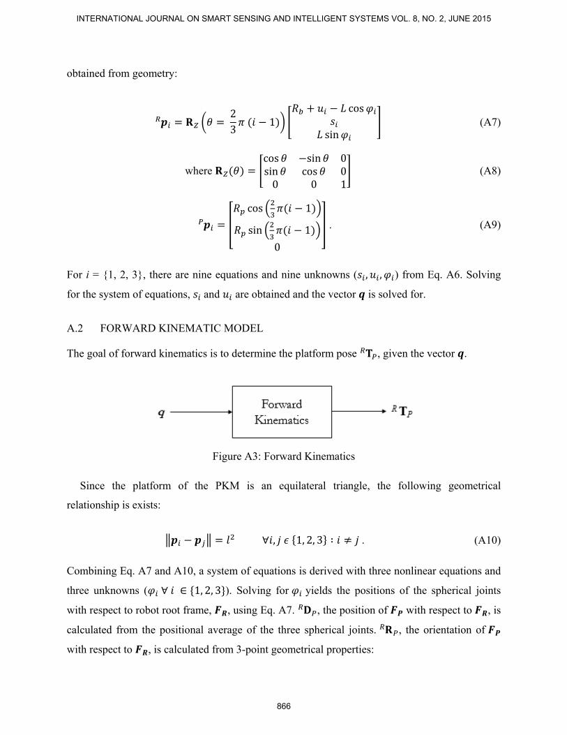
A.2 FORWARD KINEMATIC MODEL
The goal of forward kinematics is to determine the platform pose , given the vector .
Figure A3: Forward Kinematics
Since the platform of the PKM is an equilateral triangle, the following geometrical
relationship is exists:
∀ , 1, 2, 3 ∶ . (A10)
Combining Eq. A7 and A10, a system of equations is derived with three nonlinear equations and
three unknowns ( ∀ ∈ 1, 2, 3 ). Solving for yields the positions of the spherical joints
with respect to robot root frame, , using Eq. A7. , the position of with respect to , is
calculated from the positional average of the three spherical joints. , the orientation of
with respect to , is calculated from 3-point geometrical properties:
INTERNATIONAL JOURNAL ON SMART SENSING AND INTELLIGENT SYSTEMS VOL. 8, NO. 2, JUNE 2015
866

∑
3 (A11)
√3⁄ (A12)
(A13)
(A14)
. (A15) With Eq. A11 and Eq. A15, the matrix, , can be solved for.
Erkai Zhou, Mengzhe Zhu, Alexander Hong, Goldie Nejat and Beno Benhabib, LINE-OF-SIGHT BASED 3D LOCALIZATION OF PARALLEL KINEMATIC MECHANISMS
867

Appendix B EXAMPLES OF LOCALIZATION
The following table shows the results for 20 localization simulations.
Systematic Error: 20 µm/mm
Noise: 3σ = 0.1 µm
Convergence criteria = (0.00012 mm, 0.00035°)
Table B1. Summary of 20 simulation results
Simulation Starting Pose
( )[mm, mm, mm, °, °, °
Desired Pose ( )
[mm, mm, mm, °, °, °
Converged in
Iteration #
Converged with Maximum Offset
[mm, °
1 (1, 308, -5, 10, -38, -24) (-5, 293, -8, 6, -11, -5) 3 (0.000072, 0.000123)
2 (20, 305, -27, -16, -6, -17) (2, 288, 4, -15, -7, -5) 4 (0.000060, 0.000119)
3 (-1, 300, -13, 29, 31, -23) (-8, 294, -5, 2, -1, 0) 3 (0.000069, 0.000084)
4 (-22, 300, -46, 16, 8, 14) (-8, 298, -2, -11, 8, -2) 3 (0.000108, 0.000062)
5 (-1, 304, 9, 2, 12, -1) (5, 292, 5, -12, -9, -2) 3 (0.000082, 0.000099)
6 (0, 322, -37, -9, -27, 21) (12, 304, -21, 7, -8, -2) 3 (0.000092, 0.000033)
7 (-1, 312, -5, -7, 2, 4) (5, 297, -6, -5, -13, 1) 3 (0.000071, 0.000109)
8 (10, 271, 17, -4, 0, -19) (2, 290, 11, -13, -4, -3) 3 (0.000078, 0.000146)
9 (-28, 298, 2, -35, -5, -5) (-7, 299, 6, -2, -2, 0) 3 (0.000047, 0.000103)
10 (-19, 304, -22, -8, 25, -9) (-4, 302, -14, -2, 7, -12) 3 (0.000095, 0.000094)
11 (-12, 308, -8, 12, 5, -25) (-1, 308, -24, 6, -3, -1) 3 (0.000110, 0.000132)
12 (-1, 299, -20, 20, 27, -8) (16, 299, 1, -12, -1, 3) 3 (0.000068, 0.000138)
13 (-5, 296, -17, 1, -17, 24) (-4, 313, -23, 12, 1, 4) 3 (0.000111, 0.000082)
14 (5, 294, -10, -7, -8, 31) (1, 284, 5, -12, -6, -3) 3 (0.000074, 0.000145)
15 (8, 313, -21, 34, -22, 32) (8, 313, -14, 5, -2, -2) 3 (0.000077, 0.000098)
16 (-4, 307, -22, 9, -30, -6) (5, 295, -16, 2, -20, -7) 3 (0.000081, 0.000176)
17 (10, 287, -11, 4, 18, 9) (3, 286, -9, -11, 5, 5) 3 (0.000093, 0.000079)
18 (3, 294, -29, 7, 5, 10) (5, 297, 6, -1, -1, 4) 3 (0.000052, 0.000153)
19 (-8, 288, -5, 6, 5, -17) (0, 292, 11, -13, 0, 2) 3 (0.000056, 0.000091)
20 (-12, 313, -29, 9, -6, -54) (1, 298, 5, -3, -4, -4) 3 (0.000054, 0.000075)
INTERNATIONAL JOURNAL ON SMART SENSING AND INTELLIGENT SYSTEMS VOL. 8, NO. 2, JUNE 2015
868