LindabSmoke control system · PDF filelindab | we simplify construction Mounting instruction...
18
lindab | we simplify construction Mounting instruction Lindab Smoke control system – single compartment – Duct and fittings, Smoke control dampers
Transcript of LindabSmoke control system · PDF filelindab | we simplify construction Mounting instruction...

l indab | we s impl i f y construct ion
Mounting instruction
LindabSmoke control system– single compartment – Duct and fittings, Smoke control dampers
2
Duct and fittings
Content – Duct and fittings
Introduction ...................................................................3
Intended use..................................................................3
Transport and delivery ...................................................4
Storage ..........................................................................4
Operation .......................................................................4
Applied Documents ......................................................4
Declaration of performance...........................................5
Revision and Maintenance ............................................5
Before mounting ............................................................6
Mounting .......................................................................6
Horizontal suspension ...................................................7
Vertical suspension .......................................................8
Compensator .................................................................9
Grilles ..........................................................................10
Silencers .....................................................................10
Content – Smoke dampers
Introduction .................................................................11
Intended use................................................................11
Transport and delivery .................................................12
Storage ........................................................................12
Operation .....................................................................12
Applied Documents .....................................................12
Declaration of performance.........................................13
Revision and Maintenance ..........................................13
Before mounting ..........................................................13
Mounting .....................................................................14
Connection ..................................................................15
Inspection of the damper ............................................16

3
Duct and fittings
IntroductionThis mounting instruction refers to a circular smoke control system for single compartment tested in two hours at a temperature of 600°C at a positive pressure of +500 Pa and negative pressure of -1500 Pa in horizontal and vertical position (E600 120 (ve - ho) S 1500 single) according to the following standards:
Classification: EN 13501-4 Fire classification of construction products and building elements.
Classification using data from fire resistance tests on com-ponents of smoke control systems.
Test Method: EN 1366-9 Fire resistance tests for service installations Single compart-ment smoke extraction ducts.
Requirements: EN 12101-7 Smoke and heat control systems.
Smoke duct sections
Intended useThe system is a part of a smoke and fire protect system and is designed to reach the following tar-gets:
• Extract smoke for 2 hours during the fire
• Reduce temperatures during the fire
• Create an non-smoke layer
• Protect the property
This system represents a part of the smoke and fire protection project and shall be designed by a fire expert.
The products used in system should not be larger than dimension Ø1000.

4
Duct and fittings
Transport and deliveryThe delivery contains smoke control duct system marked by a CE label on the outside of the duct.
The transport is performed by common transport means. Components that are free loaded should be secured in such a way that any deformation and damage to the components will be eliminated. The transport vehicle must be covered to prevent dust, debris and humidity to damage the components.
Components are delivered without an acceptance at a supplier´s as default. If an acceptance at a supplier´s is required, it is necessary to state this requirement in the order-purchase contract.
A buyer or his/her representative is obliged in terms of good acceptance to on site check these according to the delivery documentation. Visible defects and amount shortages are to be noticed in the transporter´s transport sheet immediately.
StorageThe goods should be stored inside and protected to prevent dust, debris and humidity to damage the goods.
OperationBefore starting the system it is necessary to check the system for damages and that it is consistent to the fire expert design.
The system can be used only in compliance with determined conditions (pressure, temperature etc.).
Applied Documents This system has been certified together with hangers, flanges, sealing material, silencers, grilles and compensators. All the components shall be used in the same way they were used during the tests. No substitution of any components of the system is possible. Producers of the system:
Lindab Kft, Állomás út 1/a, 2051 Biatorbágy, Hungary
Lindab s.r.l, Via Verga 82, 10036 Settimo Torinese, Italy
Lindab s.r.o, Na Hůrce 1081/6, 161 00 Praha 6, Czech Republic
Oy Lindab Ab, Kankitie 3, 40320 Jyväskylä, Finland
Oy Lindab Ab, Juvan teollisuukatu 3, 01230 Espoo, Finland
Lindab AS, Saha-Loo tee 4, Iru küla, 74206 Jõelähtme vald, Harjumaa, Estonia

5
Duct and fittings
Declaration of performanceThe system is CE marked with the declaration of performance Circular smoke control system single compartment with CPR nr. 0370-CPR-2828.
Revision and MaintenanceFollowing features shall be checked up during a revision of the system at least once a year:
• All parts of the system are to be installed according to this mounting instruction.
• System components must not be damaged in any way; duct work cross-section must not be reduced in any way.
• All connections and fl anges are to be tightened and properly connected.
• The system weight is to be evenly distributed over the hangers and not exceeding the maxi-mum weight load for the specifi c hanger.
• If thermal expansion compensating devices are used, these compensating devices shall be prepared for utmost absorption of eventually system dilatation at their extreme positions.
• There must not be any fl ammable bodies on the duct work surface and 50 mm away from the system itself.
6
Duct and fittings
Before mountingBefore starting the mounting of the system it is necessary to inspect all components to make sure that they are correct according to the project documentation and to make sure they have not been damaged during transport or storage. When handling the products on site it is important to be careful so that they don’t get damaged and their properties change.
Mounting of the system should only be done by trained professionals equipped with the correct protective equipment and tools. The mounting of the system should always be performed according to valid documentation from the manufacturer.
The system should never be used as a supporting part of the building.
In order to achieve a good result, ensure you have:
• A well-organised and protected storage site for ducts and other parts that are to be assemb-led.
• A properly planned assembly sequence in accordance with the instructions.
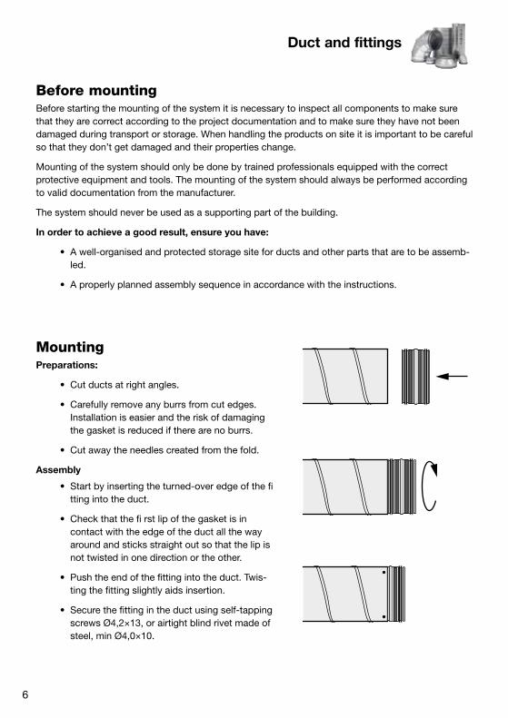
MountingPreparations:
• Cut ducts at right angles.
• Carefully remove any burrs from cut edges. Installation is easier and the risk of damaging the gasket is reduced if there are no burrs.
• Cut away the needles created from the fold.
Assembly
• Start by inserting the turned-over edge of the fi tting into the duct.
• Check that the fi rst lip of the gasket is in contact with the edge of the duct all the way around and sticks straight out so that the lip is not twisted in one direction or the other.
• Push the end of the fitting into the duct. Twis-ting the fitting slightly aids insertion.
• Secure the fitting in the duct using self-tapping screws Ø4,2×13, or airtight blind rivet made of steel, min Ø4,0×10.

7
l l
Duct and fittings
Horizontal suspension
The threaded rods shall be anchored to a massive ceiling by using expanding wall plugs with dimensions corresponding with the threaded rods.
Ønom
Threaded rod when l < 3000 mm
63-800 M8
900-1000 M10
Ønom
Distance l (mm) when using threaded rod M8
63-800 < 3000
900-1000 < 2300
Ønom
Minimum number of fasteners required
to achieve sufficient strength.
63–630 4
710–1000 6
• Fasteners should be positioned 10–15 mm from the end of the duct to prevent damage to the gasket.
• Always position fasteners at the present largest radial gap between fitting and duct. Be sure to achieve an even distribution around the circumference.
• When mounting products that requires mastic, such as saddles, to achive air tightness the mastic Soudal Firecryl must be used.

8
≤ 3000
3.
4.
2. 6.
5.
1.
4.
2.1. 3.
Duct and fittings
Vertical suspension
The system shall be suspended with recommended hinge material according to construction condi-tions and a particular system weight.
The distance between two anchoring points in the wall should not exceed 3000 mm.
• Two wall brackets (1.), CLS
• One channel (2.), RPC 41×21
• Two bolts (3.), minimum M8×35, and four washers (4.)
• Two suspension brackets (5.), WCLGM without rubber, each with four self drilling screws (6.) attached to the duct
The threaded rod can not be longer than 2 m. Two shorter threaded rods can be joined with a long nut, OSM, secured with two nuts. For suspension of the system suspension rings, UV (1.), DRSN/UVH (2.) or DRSN/UVH (3.), should be used.
9
max 10 m
min 150 mm
Duct and fittings
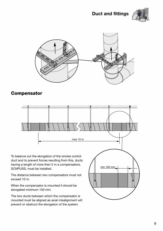
Compensator
To balance out the elongation of the smoke control duct and to prevent forces resulting from this, ducts having a length of more then 5 m a compensators, SCNPUSS, must be installed.
The distance between two compensators must not exceed 10 m.
When the compensator is mounted it should be elongated minimum 150 mm.
The two ducts between which the compensator is mounted must be aligned as axial misalignment will prevent or obstruct the elongation of the system.

10
Duct and fittings
GrillesGrilles, RGS-4 or RGS-0 , can be moun-ted into the system. It is preferred that they are mounted at the factory.
Silencers The silencers SLUSS2,SLGPUSS2 and BSLUSS2 can be used with the system.
Ød
1

11
Smoke damper
IntroductionThis mounting instruction refers to a circular smoke control dampers for single compartment tested in two hours at a temperature of 600°C at a positive pressure of +500 Pa and negative pressure of -1500 Pa in installation on a duct penetrating a vertical or horizontal wall with two relay response options: type AA (Automatic Activation) and type MA (Manual Activation). Both motorized version are suitable for a combined use in smoke control and HVAC systems (e.g. reversable system).
The damper is classifi ed as following standards:
E600 120 (ved ,hod i<->o) S 1500 C10000 AA single
E600 120 (ved ,hod i<->o) S 1500 C10000 MA single
Classification: EN 13501-4 Fire classifi cation of construction products and building elements. Classification using data from fi re resistance tests on components of smoke control systems.
Test Method: EN 1366-10 Fire resistance tests for service installations. Single compartment smoke extraction ducts.
Requirements: EN 12101-8 Smoke and heat control systems. Smoke duct sections.
Intended useThe damper is a part of a smoke and fi re protection system and is designed to reach the following targets:
• Extract smoke for 2 hours during the fire
• Reduce temperatures during the fire
• Opens the blade and remove heat and smoke from a compartment in fire
• Closes the blade to prevent the spread of heat and smoke to a safe compartment
• Create an non-smoke layer
• Protect the property
This damper represents a part of the smoke and fi re protection project and shall be designed by a fire expert.
The products used in system should not be larger than dimension Ø 630.

12
Smoke damper
Transport and deliveryThe delivery contains smoke control damper marked by a CE label on the outside of the product.
The transport is performed by common transport means. Components that are free loaded should be secured in such a way that any deformation and damage to the components will be elimina-ted. The transport vehicle must be covered to prevent dust, debris and humidity to damage the components.
Components are delivered without an acceptance at a supplier´s as default. If an acceptance at a supplier´s is required, it is necessary to state this requirement in the orderpurchase contract.
A buyer or his/her representative is obliged in terms of good acceptance to on site check these according to the delivery documentation. Visible defects and amount shortages are to be noticed in the transporter´s transport sheet immediately.
StorageThe goods should be stored inside and protected to prevent dust, debris and humidity to damage the goods.
OperationAll smoke dampers have a electrical actuator. They are designed to be installed indoor in a smoke evacuation and standard HVAC system.
Before starting the system it is necessary to check the system for damages and that it is consis-tent to the fi re expert design.
The system can be used only in compliance with determined conditions (pressure, temperature etc.).
Applied DocumentsThis smoke damper has been certifi ed together with the Lindab smoke evacuation system (see “duct and fi ttings” secion on this manual). The damper shall be used in the same way it was used during the tests. No manipolation or substitution of any components of the damper is possible.
Producers of the smoke damper:
MP3 S.r.l., via G. La Pira 9, 35012 Camposampiero (PD), Italy - belongs to the holding Lindab.
13
Smoke damper
Declaration of performanceThe damper is CE marked with the declaration of performance according to EN12101-8 as a circular smoke control damper single compartment with CPR nr. 1812-CPR-1189.
Revision and MaintenanceFollowing features shall be checked up during a revision of the damper at least once a year:
• All parts are to be installed according to this mounting instruction.
• The damper must not be damaged in any way, the cross-section of the casing, the motor and the covering box of the motor must not be damaged in any way.
• All connections with the smoke evacuation system are to be tightened and properly con-nected.
• The ducts connected to the damper must be suspended or supported in order to bear the damper’s weight too.
• There must not be any flammable bodies on the damper surface and 50 mm away from the system itself.
Before mountingBefore starting the mounting of the damper it is necessary to inspect all components to make sure that they are correct according to the project documentation and to make sure they have not been damaged during transport or storage. When handling the products on site it is important to be careful so that they don’t get damaged and their properties change.
Mounting of the damper should only be done by trained professionals equipped with the correct protective equipment and tools. The mounting of the damper should always be performed accor-ding to valid documentation from the manufacturer.
The damper should never be used as a supporting part of the building.
In order to achieve a good result, ensure you have:
• A well-organised and protected storage site for components and other parts that are to be assembled.
• A properly planned assembly sequence in accordance with the instructions.

14
Smoke damper
MountingPreparations:
• Cut ducts at right angles.
• Carefully remove any burrs from cut edges. Installation is easier and the risk of damaging the gasket is reduced if there are no burrs.
• Cut away the needles created from the fold.
Assembly
• Start by inserting the turned-over edge of the damper into the duct.
• Check that the fi rst lip of the gasket is in contact with the edge of the duct all the way around and sticks straight out so that the lip is not twisted in one direction or the other.
• Push the end of the damper into the duct. Twisting the damper slightly aids insertion.
• Secure the damper in the duct using self-tapping screws Ø4,2×13.
• Fasteners should be positioned on the duct close the damper (minimum 10-15 mm) to support itself weight and to pre-vent damage to the gasket.
• The damper must be installed on certifi ed and CE marked smoke control system. Note that the damper is a compontent of the system, please read and follow the mounting instruction of the whole smoke control system itself (page 6).
Ønom
Minimum number of fasteners
required to achievesuffi cient strength.
63-630 4

<3°
3
<87°
21 S1 S2 S3 S4 S5 S6
N L1!
<3°
3
<87°
21 S1 S2 S3 S4 S5 S6
– +
~T
!
BLE230 BLE24
15
Smoke damper
Note
• Caution: Main power supply voltage!
• Parallel connection of several actuators possible. Power consumption and switching thresholds must be observed!
Note
• Supply via safety isolation transformer!
• Parallel connection of several actuators possible. Power consumption and switching thresholds must be observed!
Connection
BLE24 BLE230
Power supply .................................... AC/DC 19.2 28,8 V, AC 198-264 V, 50/60 Hz 50/60 Hz
Power consumption ......................... 7,5 W 5 W
For wire sizing .................................. 9 VA 12 VA
Connection ....................................... Cable 1 m, 3×0,75 mm² Cable 1 m, 3×0,75 mm²
Operative angle ................................ Max. 90° Max 105°
Torque at rated voltage..................... Min. 15 Nm Min. 15 Nm
Direction of rotation .......................... Selected by mounting L/R Selected by mounting L/R
Position indication ............................ Mechanical with pointer Mechanical with pointer
Running time .................................... <30 s for 90° <30 s for 90°
Sound power level ............................ Max. 62 dB (A) Max. 62 dB (A)
Protection class ................................ III Safety extra-low voltage II totally insulated
Protection type ................................. IP 54 IP54
Ambient temperature range ............. -30 to +50°C -40 to + 80°C
Ambient moisture ............................. 95 % RH 95 % RH
Mode of operation ............................ 2-wire open-close control. The actuator is overload-proof and can thus remain energised even at the end stops.
Signalling .......................................... Two microswitches with fi xed settings are installed in the actuator for indicating the damper end positions. The position of the damper blade can be read off on a mechanism position indicator.
Manual operation ............................. The crank handle supplied with the actuator allows it to be operated manually.

16
Smoke damper
Inspection of the damperEach damper should be inspected after installation and every 12 months .
The damper is part of the SHEVS. Therefore the system must be checked as specified in its ope-rational and maintenance according to the national requirements


www.lindab.com
At Lindab, good thinking is a philosophy that guides
us in everything we do. We have made it our mission
to create a healthy indoor climate – and to simplify
the construction of sustainable buildings. We do that
by designing innovative products and solutions that
are easy to use, as well as offering efficient availability
and logistics. We are also working on ways to reduce
our impact on our environment and climate. We do
that by developing methods to produce our solutions
using a minimum of energy and natural resources,
and by reducing negative effects on the environment.
We use steel in our products. It’s one of few materi-
als that can be recycled an infinite number of times
without losing any of its properties. That means less
carbon emissions in nature and less energy wasted.
We simplify construction
EN
201
7-10
-15