lindab | dampers and measure units TECHNICAL DATA Shut-off ...
3
KLM dampers are the most applied balancing dampers to regulate the required airflow. These dampers are equipped with a turning blade, adjustable from 0 – 90° (90° is closed). A certain flow of air will always leak through even when the blade is closed. The KLM damper has a turning, circular blade. The blade is stepless adjustable 0-90°. The damper is used in cases of lower demands for shut-off capacity. The damper admits an insulation thickness of approx. 50 mm. In appropriate cases the damper can be used for regulation. Setting the angle α α = 0° = open blade, α = 90° = closed blade General features of the Air Spiralo ® KEN-LOK dampers: less leakage loss and minimal noise pollution in the system. The unique KEN-LOK rubber seal lead to quick and easy mounting of the dampers: Plug & Play. Unique features: • Short built-in lengths • A wide range of KLM models for all your needs • KLM dampers can be easily insulated even after installation • Rigid construction, easy to install through ‘Soft-Edge’-technology • Certification according to EN12237, VTT SERT R022-4 and DW144 • Air Spiralo ® products comply to the European standards KLM • Metal cup • Stepless adjustable • Blade attached by a synthetic bush at both ends • Not suitable for 100% closing Technical specifications Pressure loss graphs with noise data for dimensioning. • The solid curves show the pressure drop, Δpt, over the damper as a function of flow q and setting angle α. • The dashed curves give the A-weighted sound power data, LWA, in dB to the duct. TECHNICAL DATA Air Spiralo ® KEN-LOK Single blade damper with adjustment cup AIR SPIRALO ® KEN-LOK DAMPERS - KLM 20 d 1 45 l p l 1 l 1 l p l Example: Given: Dimension Ø100 Flow 60 l/s Pressure drop 200 Pa Obtained from graph: Setting angle 38° Sound power level 63dB(A) α VENTILATION DUCTS & FITTINGS Air Spiralo ® • Kennemer Spiralo BV • PO Box 51 • 1740 AB Schagen T +31 224 210 062 • [email protected] • www.airspiralo.com Member of Air Spiralo ® Group
Transcript of lindab | dampers and measure units TECHNICAL DATA Shut-off ...

KLM dampers are the most applied balancing dampers to regulate the required airflow. These dampers are equipped with a turning blade, adjustable from 0 – 90° (90° is closed). A certain flow of air will always leak through even when the blade is closed. The KLM damper has a turning, circular blade. The blade is stepless adjustable 0-90°. The damper is used in cases of lower demands for shut-off capacity. The damper admits an insulation thickness of approx. 50 mm. In appropriate cases the damper can be used for regulation.
Setting the angle α α = 0° = open blade, α = 90° = closed blade
General features of the Air Spiralo® KEN-LOK dampers: less leakage loss and minimal noise pollution in the system. The unique KEN-LOK rubber seal lead to quick and easy mounting of the dampers: Plug & Play.
Unique features:• Short built-in lengths• A wide range of KLM models for all your needs• KLM dampers can be easily insulated even after installation• Rigid construction, easy to install through ‘Soft-Edge’-technology• Certification according to EN12237, VTT SERT R022-4 and DW144• Air Spiralo® products comply to the European standards
KLM• Metal cup• Stepless adjustable• Blade attached by a synthetic bush at both ends• Not suitable for 100% closing
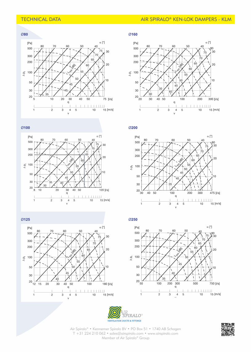
Technical specificationsPressure loss graphs with noise data for dimensioning.• The solid curves show the pressure drop, Δpt, over the damper as a function of flow q and setting angle α.• The dashed curves give the A-weighted sound power data, LWA, in dB to the duct.
TECHNICAL DATA
Air Spiralo® KEN-LOKSingle blade damper with adjustment cup
AIR SPIRALO® KEN-LOK DAMPERS - KLM
KLM0002013-03-26
20
d 145
lp l1 l1 lpl
Example:Given: Dimension Ø100 Flow 60 l/s Pressure drop 200 Pa
Obtained from graph: Setting angle 38° Sound power level 63dB(A)
254 We reserve the right to make changes without prior notice
1
2
3
4
5
6
7
8
9
10
11
12
13
14
15
16
17
18
Shut-off damper DSU
l indab | dampers and measure units
DescriptionHas a turning, circular blade. The blade is stepless adjustable 0–90°. The damper is used when you have lower demands for shut-off capacity. The damper admits an insulation thick-ness of approx. 50 mm.
The damper can on occations be used for regulation.
Setting angle α α = 0° = open blade, α = 90° = closed blade
There is a separate assembly, measuring, balancing and maintenance instruction for this product.
Ø 63–1000 fullfills pressure class A in closed position.
The cup at Ø 80–630 can be complemented with the special insulation cup IK at insulation thicker than 50 mm.
DimensionsØ 80–630
Ø 800–1000
α
Reinforced blade
Ordering exampleDSU 160
ProductDimension Ød1
Ød1nom
lmm
mkg
Sealing class past closed blade
63 100 0,30 080 100 0,35 0
100 100 0,40 0112 100 0,44 0125 100 0,49 0140 100 0,54 0150 100 0,57 0160 100 0,67 0180 100 0,73 0200 100 0,86 0224 100 1,10 0250 100 1,31 0280 100 1,51 0300 100 1,65 0315 100 1,81 0355 100 2,00 0400 100 2,91 1450 100 3,90 1500 115 4,92 1560 115 6,01 1600 115 6,40 1630 115 6,92 1800 230 19,0 1
1000 230 30,0 1
45
l
Ød 1
Ød
1
l
DSU
VENTILATION DUCTS & FITTINGS
Air Spiralo® • Kennemer Spiralo BV • PO Box 51 • 1740 AB SchagenT +31 224 210 062 • [email protected] • www.airspiralo.com
Member of Air Spiralo® Group
Ø80
TECHNICAL DATA
We reserve the right to make changes without prior notice 255
1
2
3
4
5
6
7
8
9
10
11
12
13
14
15
16
17
18
Shut-off damper DSU
l indab | dampers and measure units
Technical dataPressure drop graphs with noise data for dimensioning
The solid curves show the pressure drop, Δpt, over the damper as a function of flow q, and setting angle α.
The dashed curves give the A-weighted sound power data, LWA, in dB to the duct.
ExampleGiven Dimension Ø100
Flow 60 l/sPressure drop 200 Pa
Obtained from graphSetting angle 38°Sound power level 63 dB (A)
Property
Ø 8
0–31
5
Ø 4
00
Ø 5
00
Ø 6
30
Ø 8
00–1
000
The blade is set via a knob in a protec-tive cup.
× × × ×
The setting of the blade is read against an embossed scale at the rim of the cup.
× × × ×
The blade is locked with two screws, type Pozidriv (PZD2).
× × × ×
The blade has reinforced locking with a sturdy wing nut.
×
The blade is reinforced. × × ×The blade is additionally reinforced. ×With sturdy handle. × × ×With additionally reinforced handle. ×With reinforced stop beads. × ×The axle is reinforced. ×The damper can be delivered prepared for motor.
× × × ×
The damper can be delivered with mo-tor.
× × × × ×
Ø80
v
q
[Pa] α [°]
Δ p t
500
100
200
300
50
20
30
5 10 20 30 40 50 75
1 2 3 4 5 10 15
80 70 60 50 40
10
20
30
[l/s]
[m/s]
4035
75
45
50
55
60
65
70
L WA
[dB]
Ø100
v
q
[Pa] α [°]
Δ p t
500
100
200
300
50
20
30
8 10 20 30 40 50 120
1 2 3 4 5 10 15
80 70 60 50 40
10
20
30
[l/s]
[m/s]
4030
35
75
45
50
55
60
65
70
L WA [d
B]
Ø125
256 We reserve the right to make changes without prior notice
1
2
3
4
5
6
7
8
9
10
11
12
13
14
15
16
17
18
Shut-off damper DSU
l indab | dampers and measure units
Ø112
v
q
[Pa] α [°]
Δ p t
500
100
200
300
50
20
30
10 20 40 50 100 15030
1 2 3 4 5 10 15
70 60 50 40
20
10
809030
[l/s]
[m/s]
Ø125
v
q
[Pa] α [°]
Δ p t
500
100
200
300
50
20
30
12 15 20 30 40 50 100 180
1 2 3 4 5 10 15
80 70 60 50 40
10
20
30
[l/s]
[m/s]
40
75
45
50
55
60
65
70
L WA [d
B]
Ø140
v
q
[Pa] α [°]
Δ p t
500
100
200
300
50
20
30
15 20 40 50 150100 23030
1 2 3 4 5 10 15
70 60 50 40
20
10
8090
30
[l/s]
[m/s]
Ø150
v
q
[Pa] α [°]
Δ p t
500
100
200
300
50
20
30
17 20 40 50 200150100 27030
1 2 3 4 5 10 15
70 60 50 40
20
10
80
30
[l/s]
[m/s]
Ø160
v
q
[Pa] α [°]
Δ p t
500
100
200
300
50
20
30
20 30 40 50 100 200 300
1 2 3 4 5 10 15
80 70 60 50 40
10
20
30
[l/s]
[m/s]
4035
30
75
80
45
50
55
60
65
70
L WA [d
B]
Ø180
v
q
[Pa] α [°]
Δ p t
500
100
200
300
50
20
30
25 150 200 30040 50 100 38030
1 2 3 4 5 10 15
70 60 50 40
20
10
80 30
[l/s]
[m/s]
Ø200
256 We reserve the right to make changes without prior notice
1
2
3
4
5
6
7
8
9
10
11
12
13
14
15
16
17
18
Shut-off damper DSU
l indab | dampers and measure units
Ø112
v
q
[Pa] α [°]
Δ p t
500
100
200
300
50
20
30
10 20 40 50 100 15030
1 2 3 4 5 10 15
70 60 50 40
20
10
809030
[l/s]
[m/s]
Ø125
v
q
[Pa] α [°]
Δ p t
500
100
200
300
50
20
30
12 15 20 30 40 50 100 180
1 2 3 4 5 10 15
80 70 60 50 40
10
20
30
[l/s]
[m/s]
40
75
45
50
55
60
65
70
L WA [d
B]
Ø140
v
q
[Pa] α [°]
Δ p t
500
100
200
300
50
20
30
15 20 40 50 150100 23030
1 2 3 4 5 10 15
70 60 50 40
20
10
8090
30
[l/s]
[m/s]
Ø150
v
q
[Pa] α [°]
Δ p t
500
100
200
300
50
20
30
17 20 40 50 200150100 27030
1 2 3 4 5 10 15
70 60 50 40
20
10
80
30
[l/s]
[m/s]
Ø160
v
q
[Pa] α [°]
Δ p t
500
100
200
300
50
20
30
20 30 40 50 100 200 300
1 2 3 4 5 10 15
80 70 60 50 40
10
20
30
[l/s]
[m/s]
4035
30
75
80
45
50
55
60
65
70
L WA [d
B]
Ø180
v
q
[Pa] α [°]
Δ p t
500
100
200
300
50
20
30
25 150 200 30040 50 100 38030
1 2 3 4 5 10 15
70 60 50 40
20
10
80 30
[l/s]
[m/s]
Ø100
We reserve the right to make changes without prior notice 255
1
2
3
4
5
6
7
8
9
10
11
12
13
14
15
16
17
18
Shut-off damper DSU
l indab | dampers and measure units
Technical dataPressure drop graphs with noise data for dimensioning
The solid curves show the pressure drop, Δpt, over the damper as a function of flow q, and setting angle α.
The dashed curves give the A-weighted sound power data, LWA, in dB to the duct.
ExampleGiven Dimension Ø100
Flow 60 l/sPressure drop 200 Pa
Obtained from graphSetting angle 38°Sound power level 63 dB (A)
Property
Ø 8
0–31
5
Ø 4
00
Ø 5
00
Ø 6
30
Ø 8
00–1
000
The blade is set via a knob in a protec-tive cup.
× × × ×
The setting of the blade is read against an embossed scale at the rim of the cup.
× × × ×
The blade is locked with two screws, type Pozidriv (PZD2).
× × × ×
The blade has reinforced locking with a sturdy wing nut.
×
The blade is reinforced. × × ×The blade is additionally reinforced. ×With sturdy handle. × × ×With additionally reinforced handle. ×With reinforced stop beads. × ×The axle is reinforced. ×The damper can be delivered prepared for motor.
× × × ×
The damper can be delivered with mo-tor.
× × × × ×
Ø80
v
q
[Pa] α [°]
Δ p t
500
100
200
300
50
20
30
5 10 20 30 40 50 75
1 2 3 4 5 10 15
80 70 60 50 40
10
20
30
[l/s]
[m/s]
4035
75
45
50
55
60
65
70
L WA
[dB]
Ø100
v
q
[Pa] α [°]
Δ p t
500
100
200
300
50
20
30
8 10 20 30 40 50 120
1 2 3 4 5 10 15
80 70 60 50 40
10
20
30
[l/s]
[m/s]
4030
35
75
45
50
55
60
65
70
L WA [d
B]
Ø160
Ø250
AIR SPIRALO® KEN-LOK DAMPERS - KLM
We reserve the right to make changes without prior notice 257
1
2
3
4
5
6
7
8
9
10
11
12
13
14
15
16
17
18
Shut-off damper DSU
l indab | dampers and measure units
Ø200
v
q
[Pa] α [°]
Δ p t
500
100
200
300
50
20
30
30 100 200 30040 50 475
1 2 3 4 5 10 15
80 70 60 50 40
10
20
30
[l/s]
[m/s]
40
35
80
4550
55
60
65
75
70
L WA [d
B]
Ø224
v
q
[Pa] α [°]
Δ p t
500
100
200
300
50
20
30
40 20015050 100 600300 400
1 2 3 4 5 10 15
70 60 50 40
20
10
30
[l/s]
[m/s]
Ø250
v
q
[Pa] α [°]
Δ p t
500
100
200
300
50
20
30
50 100 200 300 500 750
1 2 3 4 5 10 15
80 70 60 50 40
10
20
30
[l/s]
[m/s]
40
35
80
45
50
5560
6570
75
L WA
[dB]
Ø280
v
q
[Pa] α [°]
Δ p t
500
100
200
300
50
20
30
60 100 300 400 500 950200
1 2 3 4 5 10 15
70 60 50 40
20
10
8030
[l/s]
[m/s]
Ø300
v
q
[Pa] α [°]
Δ p t
500
100
200
300
50
20
30
70 100 300 400 500 1000200
1 2 3 4 5 10 15
70 60 50 40
20
30
[l/s]
[m/s]
Ø315
v
q
[Pa] α [°]
Δ p t
500
100
200
300
50
20
30
80 100 200 300 500 1200
1 2 3 4 5 10 15
80 70 60 50 40
10
20
30
[l/s]
[m/s]
403530
80
45
50
55
60
65
70
L WA [d
B]
VENTILATION DUCTS & FITTINGS
Air Spiralo® • Kennemer Spiralo BV • PO Box 51 • 1740 AB SchagenT +31 224 210 062 • [email protected] • www.airspiralo.com
Member of Air Spiralo® Group

TECHNICAL DATA
Ø315
Ø630Ø400
Ø500
We reserve the right to make changes without prior notice 257
1
2
3
4
5
6
7
8
9
10
11
12
13
14
15
16
17
18
Shut-off damper DSU
l indab | dampers and measure units
Ø200
v
q
[Pa] α [°]
Δ p t
500
100
200
300
50
20
30
30 100 200 30040 50 475
1 2 3 4 5 10 15
80 70 60 50 40
10
20
30
[l/s]
[m/s]
40
35
80
4550
55
60
65
75
70
L WA [d
B]
Ø224
v
q
[Pa] α [°]
Δ p t
500
100
200
300
50
20
30
40 20015050 100 600300 400
1 2 3 4 5 10 15
70 60 50 40
20
10
30
[l/s]
[m/s]
Ø250
v
q
[Pa] α [°]
Δ p t
500
100
200
300
50
20
30
50 100 200 300 500 750
1 2 3 4 5 10 15
80 70 60 50 40
10
20
30
[l/s]
[m/s]
40
35
80
45
50
5560
6570
75
L WA
[dB]
Ø280
v
q
[Pa] α [°]
Δ p t
500
100
200
300
50
20
30
60 100 300 400 500 950200
1 2 3 4 5 10 15
70 60 50 40
20
10
8030
[l/s]
[m/s]
Ø300
v
q
[Pa] α [°]
Δ p t
500
100
200
300
50
20
30
70 100 300 400 500 1000200
1 2 3 4 5 10 15
70 60 50 40
20
30
[l/s]
[m/s]
Ø315
v
q
[Pa] α [°]
Δ p t
500
100
200
300
50
20
30
80 100 200 300 500 1200
1 2 3 4 5 10 15
80 70 60 50 40
10
20
30
[l/s]
[m/s]
403530
80
45
50
55
60
65
70
L WA [d
B]
AIR SPIRALO® KEN-LOK DAMPERS - KLM
258 We reserve the right to make changes without prior notice
1
2
3
4
5
6
7
8
9
10
11
12
13
14
15
16
17
18
Shut-off damper DSU
l indab | dampers and measure units
Ø355
v
q
[Pa] α [°]
Δ p t
500
100
200
300
50
20
30
100 200 400 500 1000 1500300
1 2 3 4 5 10 15
70 60 50 40
20
30
[l/s]
[m/s]
Ø400
v
q
[Pa] α [°]
Δ p t
500
100
200
300
50
20
30
130 200 300 1000500 1900
1 2 3 4 5 10 15
80 70 60 50 40
10
20
30
[l/s]
[m/s]
4035
80
45
50
55
60
65
75
70
L WA
[dB]
Ø450
v
q
[Pa] α [°]
Δ p t
500
100
200
300
50
20
30
160 200 400 500 20001000 2500300
1 2 3 4 5 10 15
70 60 50 40
20
10
0
80
30
[l/s]
[m/s]
Ø500
v
q
[Pa] α [°]
Δ p t
500
100
200
300
50
20
30
200 1000 2000300 500 3000
1 2 3 4 5 10 15
70 60 50 40
10
20
30
[l/s]
[m/s]
4035
80
45
50
55
60
65
70
75
85
L WA [d
B]
Ø560
v
q
[Pa] α [°]
Δ p t
500
100
200
300
50
20
30
250 300 500 1000 2000 3700400
1 2 3 4 5 10 15
70 60 50 40
20
0
10
30
[l/s]
[m/s]
Ø600
v
q
[Pa] α [°]
Δ p t
500
100
200
300
50
20
30
280 1000400 500 2000 3000 4200
1 2 3 4 5 10 15
70 60 50 40
20
10
0
30
[l/s]
[m/s]
We reserve the right to make changes without prior notice 259
1
2
3
4
5
6
7
8
9
10
11
12
13
14
15
16
17
18
Shut-off damper DSU
l indab | dampers and measure units
Ø630
v
q
[Pa] α [°]
Δ p t
500
100
200
300
50
20
30
300 1000 2000 3000500 4700
1 2 3 4 5 10 15
70 60 50 40
10
20
30
[l/s]
[m/s]
40
8580
4550
55
60
65
7075
L WA
[dB]
Ø710
v
q
[Pa] α [°]
Δ p t
500
100
200
300
50
20
30
400 500 2000 3000 4000 60001000
1 2 3 4 5 10 15
60 50 30
0
10
20
40
[l/s]
[m/s]
Ø800
v
q
[Pa] α [°]
Δ p t
500
100
200
300
50
20
30
500 1000 2000 5000 7500
1 2 3 4 5 10 15
80 70 60 50 40
10
20
30
[l/s]
[m/s]
4035
30
45
50
55
60
65
70
L WA [d
B]
Ø900
v
q
[Pa] α [°]
Δ p t
500
100
200
300
50
20
30
630 20000 3000 5000 95001000
1 2 3 4 5 10 15
70 60 50 40
20
10
30
[l/s]
[m/s]
Ø1000
v
q
[Pa] α [°]
Δ p t
500
100
200
300
50
20
30
800 2000 5000 11800
1 2 3 4 5 10 15
80 70 60 50 40
10
20
30
[l/s]
[m/s]
40
3035
45
50
55
60
65
70
L WA
[dB]
VENTILATION DUCTS & FITTINGS
Air Spiralo® • Kennemer Spiralo BV • PO Box 51 • 1740 AB SchagenT +31 224 210 062 • [email protected] • www.airspiralo.com
Member of Air Spiralo® Group