Limnological Research Center Core Facility Draft...
12
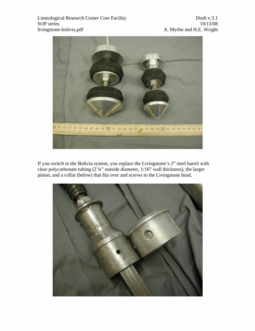
Limnological Research Center Core Facility Draft v.3.1 SOP series 10/13/08 livingstone-bolivia.pdf A. Myrbo and H.E. Wright The Livingstone-type drive rod piston corer (Wright, 1967) can be used in water up to about 30 m deep to collect successive one-meter drives of soft to consolidated lake sediment. Three people at a minimum (and preferably four or five) are required to operate the coring device, and tens of meters of core can be collected in a single day. A modification to the Livingstone, called the Bolivia corer, replaces the Livingstone’s 2” (5 cm) steel barrel with a 2 ¾” (7 cm) polycarbonate barrel, eliminating the need to extrude cores and providing superior retention of upper watery sediments. When a depth is reached at which sediments have become too tough for the polycarbonate barrel (usually at least several meters below lake floor, depending on sediment characteristics), it only takes a few minutes to switch to the steel barrel and continue in the same hole. The Bolivia can also be deployed with a square rod long enough to take 1.5-meter drives, increasing efficiency in both coring time and polycarbonate tubing utilization. The Livingstone corer consists of a head (1), square rod (2), barrel (3), and piston (4). There’s also a piston cable (not shown) and a threaded connector (5) that attaches the square rod to the drive rods (sometimes called extension rods) used to lower the corer into the water. Here it’s shown disassembled. The barrel attaches to the head with three screws. The assembled corer, with the square rod slid down inside the barrel and the piston sitting outside the barrel, is shown below.
-
Upload
truongcong -
Category
Documents
-
view
215 -
download
1
Transcript of Limnological Research Center Core Facility Draft...
Limnological Research Center Core Facility Draft v.3.1 SOP series 10/13/08 livingstone-bolivia.pdf A. Myrbo and H.E. Wright
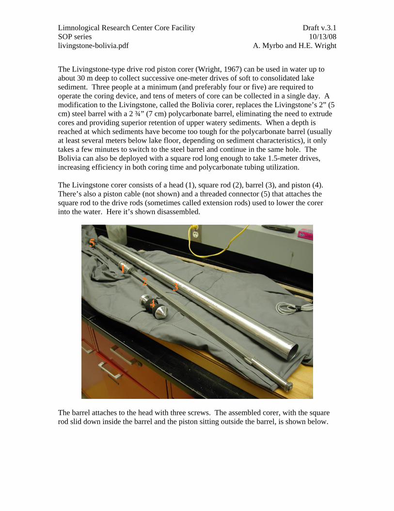
The Livingstone-type drive rod piston corer (Wright, 1967) can be used in water up to about 30 m deep to collect successive one-meter drives of soft to consolidated lake sediment. Three people at a minimum (and preferably four or five) are required to operate the coring device, and tens of meters of core can be collected in a single day. A modification to the Livingstone, called the Bolivia corer, replaces the Livingstone’s 2” (5 cm) steel barrel with a 2 ¾” (7 cm) polycarbonate barrel, eliminating the need to extrude cores and providing superior retention of upper watery sediments. When a depth is reached at which sediments have become too tough for the polycarbonate barrel (usually at least several meters below lake floor, depending on sediment characteristics), it only takes a few minutes to switch to the steel barrel and continue in the same hole. The Bolivia can also be deployed with a square rod long enough to take 1.5-meter drives, increasing efficiency in both coring time and polycarbonate tubing utilization. The Livingstone corer consists of a head (1), square rod (2), barrel (3), and piston (4). There’s also a piston cable (not shown) and a threaded connector (5) that attaches the square rod to the drive rods (sometimes called extension rods) used to lower the corer into the water. Here it’s shown disassembled.
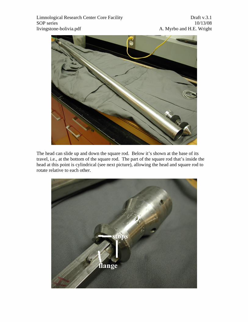
The barrel attaches to the head with three screws. The assembled corer, with the square rod slid down inside the barrel and the piston sitting outside the barrel, is shown below.
Limnological Research Center Core Facility Draft v.3.1 SOP series 10/13/08 livingstone-bolivia.pdf A. Myrbo and H.E. Wright
The head can slide up and down the square rod. Below it’s shown at the base of its travel, i.e., at the bottom of the square rod. The part of the square rod that’s inside the head at this point is cylindrical (see next picture), allowing the head and square rod to rotate relative to each other.
Limnological Research Center Core Facility Draft v.3.1 SOP series 10/13/08 livingstone-bolivia.pdf A. Myrbo and H.E. Wright
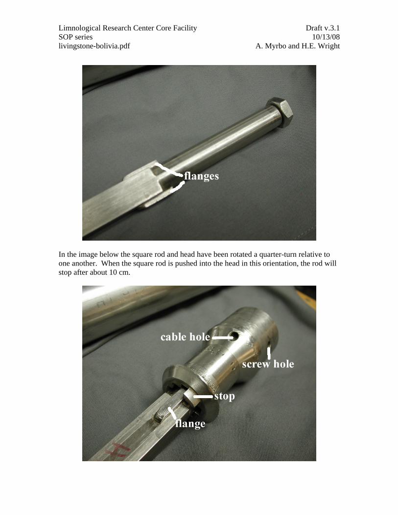
In the image below the square rod and head have been rotated a quarter-turn relative to one another. When the square rod is pushed into the head in this orientation, the rod will stop after about 10 cm.
Limnological Research Center Core Facility Draft v.3.1 SOP series 10/13/08 livingstone-bolivia.pdf A. Myrbo and H.E. Wright
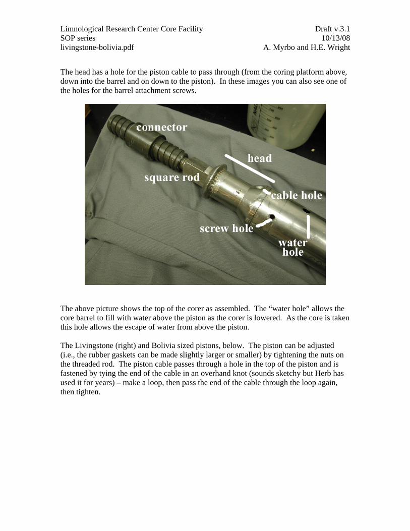
The head has a hole for the piston cable to pass through (from the coring platform above, down into the barrel and on down to the piston). In these images you can also see one of the holes for the barrel attachment screws.
The above picture shows the top of the corer as assembled. The “water hole” allows the core barrel to fill with water above the piston as the corer is lowered. As the core is taken this hole allows the escape of water from above the piston. The Livingstone (right) and Bolivia sized pistons, below. The piston can be adjusted (i.e., the rubber gaskets can be made slightly larger or smaller) by tightening the nuts on the threaded rod. The piston cable passes through a hole in the top of the piston and is fastened by tying the end of the cable in an overhand knot (sounds sketchy but Herb has used it for years) – make a loop, then pass the end of the cable through the loop again, then tighten.
Limnological Research Center Core Facility Draft v.3.1 SOP series 10/13/08 livingstone-bolivia.pdf A. Myrbo and H.E. Wright
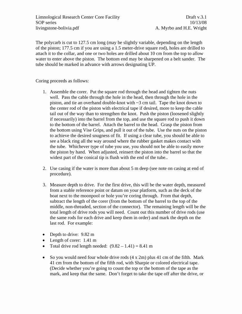
If you switch to the Bolivia system, you replace the Livingstone’s 2” steel barrel with clear polycarbonate tubing (2 ¾” outside diameter, 1/16” wall thickness), the larger piston, and a collar (below) that fits over and screws to the Livingstone head.
Limnological Research Center Core Facility Draft v.3.1 SOP series 10/13/08 livingstone-bolivia.pdf A. Myrbo and H.E. Wright
The polycarb is cut to 127.5 cm long (may be slightly variable, depending on the length of the piston; 177.5 cm if you are using a 1.5 meter-drive square rod), holes are drilled to attach it to the collar, and one or two holes are drilled about 10 cm from the top to allow water to enter above the piston. The bottom end may be sharpened on a belt sander. The tube should be marked in advance with arrows designating UP. Coring proceeds as follows:
1. Assemble the corer. Put the square rod through the head and tighten the nuts well. Pass the cable through the hole in the head, then through the hole in the piston, and tie an overhand double-knot with ~3 cm tail. Tape the knot down to the center rod of the piston with electrical tape if desired, more to keep the cable tail out of the way than to strengthen the knot. Push the piston (loosened slightly if necessarily) into the barrel from the top, and use the square rod to push it down to the bottom of the barrel. Attach the barrel to the head. Grasp the piston from the bottom using Vise Grips, and pull it out of the tube. Use the nuts on the piston to achieve the desired snugness of fit. If using a clear tube, you should be able to see a black ring all the way around where the rubber gasket makes contact with the tube. Whichever type of tube you use, you should not be able to easily move the piston by hand. When adjusted, reinsert the piston into the barrel so that the widest part of the conical tip is flush with the end of the tube..
2. Use casing if the water is more than about 5 m deep (see note on casing at end of
procedure).
3. Measure depth to drive. For the first drive, this will be the water depth, measured from a stable reference point or datum on your platform, such as the deck of the boat next to the moonpool or hole you’re coring through. From that depth, subtract the length of the corer (from the bottom of the barrel to the top of the middle, non-threaded, section of the connector). The remaining length will be the total length of drive rods you will need. Count out this number of drive rods (use the same rods for each drive and keep them in order) and mark the depth on the last rod. For example:
• Depth to drive: 9.82 m • Length of corer: 1.41 m • Total drive rod length needed: (9.82 – 1.41) = 8.41 m
• So you would need four whole drive rods (4 x 2m) plus 41 cm of the fifth. Mark
41 cm from the bottom of the fifth rod, with Sharpie or colored electrical tape. (Decide whether you’re going to count the top or the bottom of the tape as the mark, and keep that the same. Don’t forget to take the tape off after the drive, or
Limnological Research Center Core Facility Draft v.3.1 SOP series 10/13/08 livingstone-bolivia.pdf A. Myrbo and H.E. Wright
use a new symbol next to your mark if using pen so you don’t get confused on the next drive!)
• Note: It is often difficult to determine the exact water depth with a meter or
sounder as the upper sediment is very soft (a Secchi disk is a decent option, as it “floats” on soft sediment). It may thus be wise to start the first drive already 20-30 cm into the sediment, and to take a companion short surface core, using clear tubing, that begins about 30 cm above the estimated sediment-water interface. This short core can be sampled in the field while vertical, or its surface carefully fixed with floral foam.
4. One person lowers the corer, one adds drive rods, and one keeps tension on the
piston cable so that the corer doesn’t slide down the square rod. Alternately, the person lowering the corer can keep a tight grip on the cable and rod together. Lower the corer down into the water, adding drive rods (always in the same order) as necessary.
5. Stop at the desired depth (i.e., when the mark on the last drive rod reaches your
datum). The piston cable will now be fixed at this depth (this is called “setting the piston”). For the first drive, someone keeps tension on the cable (to keep the corer from sliding down the square rod) while another person fixes the cable. The best way to clamp the cable is using a climbing figure-8 attached to a carabiner, which is clipped to an eyebolt (or climbing ice screw, a wonderful thing for winter coring) on deck or another fixed object. Alternately, you can use a pair of Vise Grips or some similar tool to clamp the piston cable securely to an immobile object on the deck, but this can be damaging to the cable. Now the piston is fixed in vertical space, and is situated at the top of your first drive. • If using a figure 8: to put the cable around the figure 8, unclip the 8, put a
doubled length of cable through the larger hole and then around the outside of the smaller hole, tightening it around the waist-like part at the junction of the two loops of the 8. Clip the smaller hole back onto the carabiner. When the cable coming into and going out of the 8 are parallel, they slide, allowing you to tighten the cable after you load the cable into the 8. When the free end is pulled at a 90° angle to the fixed end, the 8 provides friction that fixes the piston. You should still hold onto the free end tightly while your companions drive.
6. The next step is to pull the square rod up and out of the core barrel, so that during
the drive the barrel can move down relative to the piston, which can no longer move down. Gently lift up the drive rod. You should be able to feel the square rod sliding out of the head. If it feels like the whole corer is coming up, and the cable gets slack, give the drive rod a shake and the corer will start to slide back down the square rod where it belongs. Continue to lift up on the drive rod until it has come up a little more than a meter and you feel the base of the square rod hit the bottom of the head. If using a figure 8, during the lifting process the person
Limnological Research Center Core Facility Draft v.3.1 SOP series 10/13/08 livingstone-bolivia.pdf A. Myrbo and H.E. Wright
handling the cable should pinch the cable and the figure 8 together to avoid slippage and keep the cable at the same length.
7. Rotate the drive rod a quarter-turn clockwise (always clockwise, or you run the
risk of unscrewing the rods from one another) until you feel the flanges on the square rod hit against the stops on the top of the head, allowing the square rod to drop into the other pair of slots. Gently lower the drive rod until you feel the flanges come to a stop inside the head (about 6 cm). You are now ready to drive. Note that the marker tape is now a meter above the datum (or 1.5 m, if using a 1.5 meter-drive square rod). • At this point the barrel and square rod are locked together, and the barrel is
free to move down over the piston. (The piston is not likely to ride up now by itself, because the barrel is full of water, and hydrostatic pressures inside and outside the barrel are equal.) As you push down for the drive, the piston stays in place and the barrel moves past it, taking the core. Your drive is a meter long (given the length of the barrel and piston), so you will push down until the tape mark is at your reference point.
8. If using a figure 8, the cable handler should now pull the free end of the cable
orthogonal to the direction of the fixed end of the cable and hold onto it tightly. Two to four people hold onto the drive rod and push down. Overcoming the initial friction of the piston in the barrel takes some force, but once the piston is moving it’s pretty easy to keep it moving. In tough sediment especially it is best to complete the full drive in a single action, in order to take advantage of momentum. You may hear the honk of the piston-barrel vibration. • Extra leverage can be applied if pipe wrenches are loosely set on the drive
rods so that they can be easily moved up or down for the best purchase. Position the pipe wrenches equally around the drive rod (opposite each other, or at equally spaced angles) so that you do not bend the rod.
9. Push down until your tape mark is at the datum. You’ll probably feel the piston
hit the square rod/head at the top of its travel. If you try to push farther, the cable will provide resistance (though it can stretch) and will prevent further penetration. • If you get stopped before the drive is complete, push again and try to complete
the drive. If you really get stopped, you can always bring up the drive and just adjust your next drive for the shortness of the present one. If this is the case, be sure to measure the leftover drive length (i.e., the distance between your tape mark and the datum) so you can adjust the next drive accordingly.
• If the sediment is really tough, you may be bending drive rods rather than penetrating further. Casing (see note at end) helps this, but casing can also bend or even break under strain. An observer (e.g., the cable handler) can watch for deflection of the drive rods and tell the pushers to stop. Everyone should let go and allow the rods to spring back up to their straight position before trying to drive further. Pushing all together, with a jerk, is the best way to overcome friction and punch through tough sediment without bending rods.
Limnological Research Center Core Facility Draft v.3.1 SOP series 10/13/08 livingstone-bolivia.pdf A. Myrbo and H.E. Wright
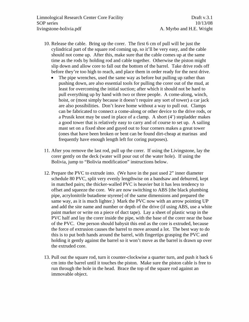
10. Release the cable. Bring up the corer. The first 6 cm of pull will be just the
cylindrical part of the square rod coming up, so it’ll be very easy, and the cable should not come up. After this, make sure that the cable comes up at the same time as the rods by holding rod and cable together. Otherwise the piston might slip down and allow core to fall out the bottom of the barrel. Take drive rods off before they’re too high to reach, and place them in order ready for the next drive. • The pipe wrenches, used the same way as before but pulling up rather than
pushing down, are also essential tools for pulling the corer out of the mud, at least for overcoming the initial suction; after which it should not be hard to pull everything up by hand with two or three people. A come-along, winch, hoist, or (most simply because it doesn’t require any sort of tower) a car jack are also possibilities. Don’t leave home without a way to pull out. Clamps can be fabricated to connect a come-along or other device to the drive rods, or a Prusik knot may be used in place of a clamp. A short (4’) stepladder makes a good tower that is relatively easy to carry and of course to set up. A sailing mast set on a fixed shoe and guyed out to four corners makes a great tower (ones that have been broken or bent can be found dirt-cheap at marinas and frequently have enough length left for coring purposes).
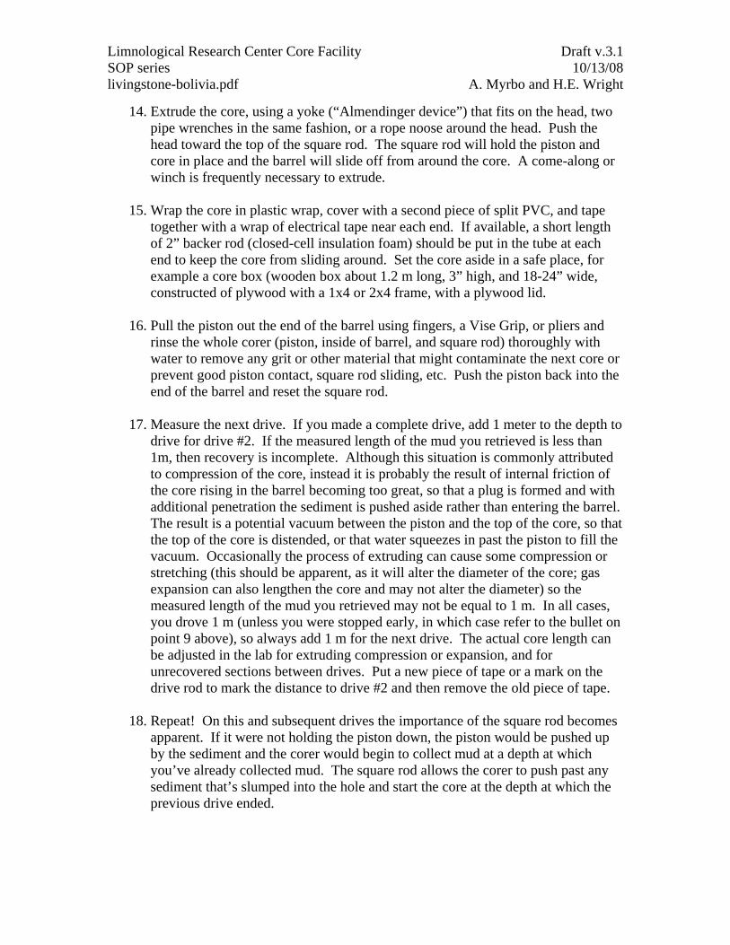
11. After you remove the last rod, pull up the corer. If using the Livingstone, lay the
corer gently on the deck (water will pour out of the water hole). If using the Bolivia, jump to “Bolivia modification” instructions below.
12. Prepare the PVC to extrude into. (We have in the past used 2” inner diameter
schedule 80 PVC, split very evenly lengthwise on a bandsaw and deburred, kept in matched pairs; the thicker-walled PVC is heavier but it has less tendency to offset and squeeze the core. We are now switching to ABS [the black plumbing pipe, acrylonitrile butadiene styrene] of the same dimensions and prepared the same way, as it is much lighter.) Mark the PVC now with an arrow pointing UP and add the site name and number or depth of the drive (if using ABS, use a white paint marker or write on a piece of duct tape). Lay a sheet of plastic wrap in the PVC half and lay the corer inside the pipe, with the base of the corer near the base of the PVC. One person should babysit this end as the core is extruded, because the force of extrusion causes the barrel to move around a lot. The best way to do this is to put both hands around the barrel, with fingertips grasping the PVC and holding it gently against the barrel so it won’t move as the barrel is drawn up over the extruded core.
13. Pull out the square rod, turn it counter-clockwise a quarter turn, and push it back 6
cm into the barrel until it touches the piston. Make sure the piston cable is free to run through the hole in the head. Brace the top of the square rod against an immovable object.
Limnological Research Center Core Facility Draft v.3.1 SOP series 10/13/08 livingstone-bolivia.pdf A. Myrbo and H.E. Wright
14. Extrude the core, using a yoke (“Almendinger device”) that fits on the head, two pipe wrenches in the same fashion, or a rope noose around the head. Push the head toward the top of the square rod. The square rod will hold the piston and core in place and the barrel will slide off from around the core. A come-along or winch is frequently necessary to extrude.
15. Wrap the core in plastic wrap, cover with a second piece of split PVC, and tape
together with a wrap of electrical tape near each end. If available, a short length of 2” backer rod (closed-cell insulation foam) should be put in the tube at each end to keep the core from sliding around. Set the core aside in a safe place, for example a core box (wooden box about 1.2 m long, 3” high, and 18-24” wide, constructed of plywood with a 1x4 or 2x4 frame, with a plywood lid.
16. Pull the piston out the end of the barrel using fingers, a Vise Grip, or pliers and
rinse the whole corer (piston, inside of barrel, and square rod) thoroughly with water to remove any grit or other material that might contaminate the next core or prevent good piston contact, square rod sliding, etc. Push the piston back into the end of the barrel and reset the square rod.
17. Measure the next drive. If you made a complete drive, add 1 meter to the depth to
drive for drive #2. If the measured length of the mud you retrieved is less than 1m, then recovery is incomplete. Although this situation is commonly attributed to compression of the core, instead it is probably the result of internal friction of the core rising in the barrel becoming too great, so that a plug is formed and with additional penetration the sediment is pushed aside rather than entering the barrel. The result is a potential vacuum between the piston and the top of the core, so that the top of the core is distended, or that water squeezes in past the piston to fill the vacuum. Occasionally the process of extruding can cause some compression or stretching (this should be apparent, as it will alter the diameter of the core; gas expansion can also lengthen the core and may not alter the diameter) so the measured length of the mud you retrieved may not be equal to 1 m. In all cases, you drove 1 m (unless you were stopped early, in which case refer to the bullet on point 9 above), so always add 1 m for the next drive. The actual core length can be adjusted in the lab for extruding compression or expansion, and for unrecovered sections between drives. Put a new piece of tape or a mark on the drive rod to mark the distance to drive #2 and then remove the old piece of tape.
18. Repeat! On this and subsequent drives the importance of the square rod becomes
apparent. If it were not holding the piston down, the piston would be pushed up by the sediment and the corer would begin to collect mud at a depth at which you’ve already collected mud. The square rod allows the corer to push past any sediment that’s slumped into the hole and start the core at the depth at which the previous drive ended.
Limnological Research Center Core Facility Draft v.3.1 SOP series 10/13/08 livingstone-bolivia.pdf A. Myrbo and H.E. Wright
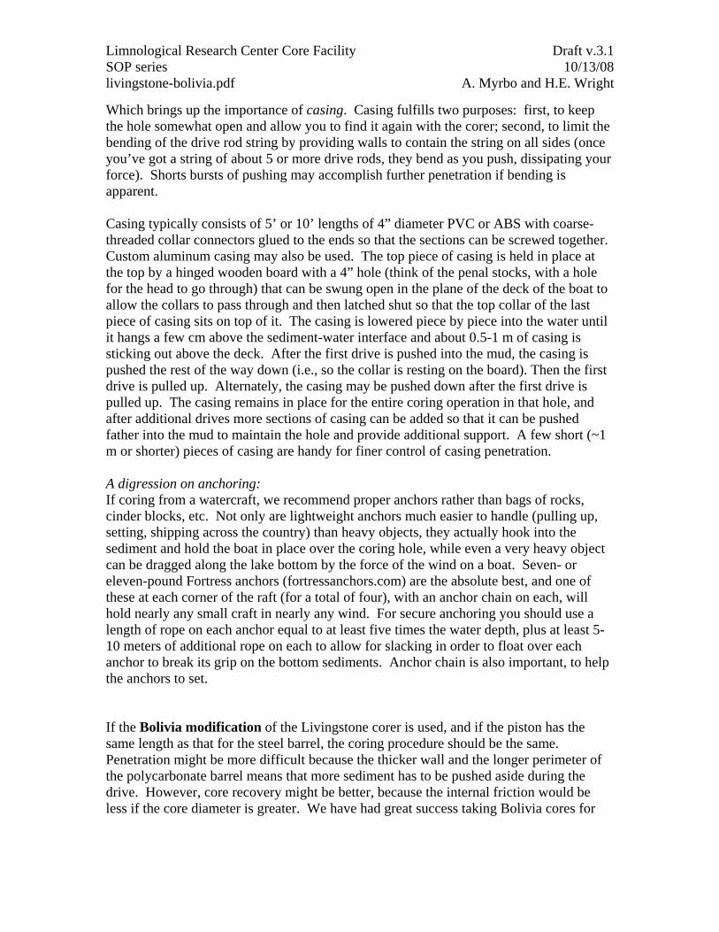
Which brings up the importance of casing. Casing fulfills two purposes: first, to keep the hole somewhat open and allow you to find it again with the corer; second, to limit the bending of the drive rod string by providing walls to contain the string on all sides (once you’ve got a string of about 5 or more drive rods, they bend as you push, dissipating your force). Shorts bursts of pushing may accomplish further penetration if bending is apparent. Casing typically consists of 5’ or 10’ lengths of 4” diameter PVC or ABS with coarse-threaded collar connectors glued to the ends so that the sections can be screwed together. Custom aluminum casing may also be used. The top piece of casing is held in place at the top by a hinged wooden board with a 4” hole (think of the penal stocks, with a hole for the head to go through) that can be swung open in the plane of the deck of the boat to allow the collars to pass through and then latched shut so that the top collar of the last piece of casing sits on top of it. The casing is lowered piece by piece into the water until it hangs a few cm above the sediment-water interface and about 0.5-1 m of casing is sticking out above the deck. After the first drive is pushed into the mud, the casing is pushed the rest of the way down (i.e., so the collar is resting on the board). Then the first drive is pulled up. Alternately, the casing may be pushed down after the first drive is pulled up. The casing remains in place for the entire coring operation in that hole, and after additional drives more sections of casing can be added so that it can be pushed father into the mud to maintain the hole and provide additional support. A few short (~1 m or shorter) pieces of casing are handy for finer control of casing penetration. A digression on anchoring: If coring from a watercraft, we recommend proper anchors rather than bags of rocks, cinder blocks, etc. Not only are lightweight anchors much easier to handle (pulling up, setting, shipping across the country) than heavy objects, they actually hook into the sediment and hold the boat in place over the coring hole, while even a very heavy object can be dragged along the lake bottom by the force of the wind on a boat. Seven- or eleven-pound Fortress anchors (fortressanchors.com) are the absolute best, and one of these at each corner of the raft (for a total of four), with an anchor chain on each, will hold nearly any small craft in nearly any wind. For secure anchoring you should use a length of rope on each anchor equal to at least five times the water depth, plus at least 5-10 meters of additional rope on each to allow for slacking in order to float over each anchor to break its grip on the bottom sediments. Anchor chain is also important, to help the anchors to set. If the Bolivia modification of the Livingstone corer is used, and if the piston has the same length as that for the steel barrel, the coring procedure should be the same. Penetration might be more difficult because the thicker wall and the longer perimeter of the polycarbonate barrel means that more sediment has to be pushed aside during the drive. However, core recovery might be better, because the internal friction would be less if the core diameter is greater. We have had great success taking Bolivia cores for
Limnological Research Center Core Facility Draft v.3.1 SOP series 10/13/08 livingstone-bolivia.pdf A. Myrbo and H.E. Wright
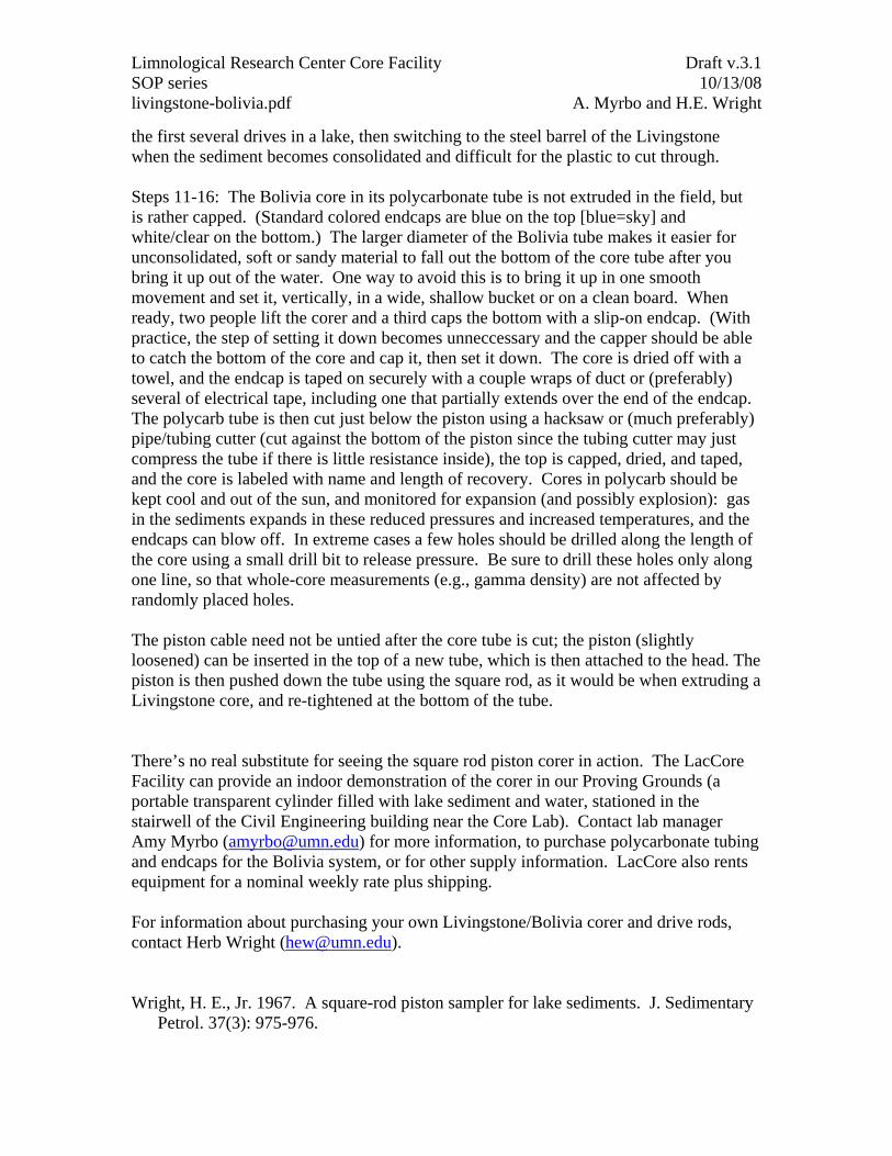
the first several drives in a lake, then switching to the steel barrel of the Livingstone when the sediment becomes consolidated and difficult for the plastic to cut through. Steps 11-16: The Bolivia core in its polycarbonate tube is not extruded in the field, but is rather capped. (Standard colored endcaps are blue on the top [blue=sky] and white/clear on the bottom.) The larger diameter of the Bolivia tube makes it easier for unconsolidated, soft or sandy material to fall out the bottom of the core tube after you bring it up out of the water. One way to avoid this is to bring it up in one smooth movement and set it, vertically, in a wide, shallow bucket or on a clean board. When ready, two people lift the corer and a third caps the bottom with a slip-on endcap. (With practice, the step of setting it down becomes unneccessary and the capper should be able to catch the bottom of the core and cap it, then set it down. The core is dried off with a towel, and the endcap is taped on securely with a couple wraps of duct or (preferably) several of electrical tape, including one that partially extends over the end of the endcap. The polycarb tube is then cut just below the piston using a hacksaw or (much preferably) pipe/tubing cutter (cut against the bottom of the piston since the tubing cutter may just compress the tube if there is little resistance inside), the top is capped, dried, and taped, and the core is labeled with name and length of recovery. Cores in polycarb should be kept cool and out of the sun, and monitored for expansion (and possibly explosion): gas in the sediments expands in these reduced pressures and increased temperatures, and the endcaps can blow off. In extreme cases a few holes should be drilled along the length of the core using a small drill bit to release pressure. Be sure to drill these holes only along one line, so that whole-core measurements (e.g., gamma density) are not affected by randomly placed holes. The piston cable need not be untied after the core tube is cut; the piston (slightly loosened) can be inserted in the top of a new tube, which is then attached to the head. The piston is then pushed down the tube using the square rod, as it would be when extruding a Livingstone core, and re-tightened at the bottom of the tube. There’s no real substitute for seeing the square rod piston corer in action. The LacCore Facility can provide an indoor demonstration of the corer in our Proving Grounds (a portable transparent cylinder filled with lake sediment and water, stationed in the stairwell of the Civil Engineering building near the Core Lab). Contact lab manager Amy Myrbo ([email protected]) for more information, to purchase polycarbonate tubing and endcaps for the Bolivia system, or for other supply information. LacCore also rents equipment for a nominal weekly rate plus shipping. For information about purchasing your own Livingstone/Bolivia corer and drive rods, contact Herb Wright ([email protected]). Wright, H. E., Jr. 1967. A square-rod piston sampler for lake sediments. J. Sedimentary
Petrol. 37(3): 975-976.