Limited Warranty - · PDF fileLimited Warranty Products manufactured by TFBP are warranted...
123
Mechanical Products Mechanical Products M06-1
Transcript of Limited Warranty - · PDF fileLimited Warranty Products manufactured by TFBP are warranted...

Mechanical Products
USA
Customer ServiceOak Creek, WIToll Free: 800 558-5236Fax: 800 877-1295
Technical ServicesTel: 866 500-4768Fax: 401 781-7317
EUROPE & MIDDLE EAST
Tyco Building Services ProductsKopersteden 1, NL-7547 TJ EnschedeP.O. Box 198, 7500 ADEnschede, The NetherlandsTel: 31-53-428-4444Fax: 31-53-428-3377
ASIA
Tyco Fire & Building Products Asia45 Tuas Avenue 9Singapore 639189Tel: +65-6861-1655Fax: +65-6861-1312
AUSTRALIA
Tyco Flow Control - Fixed Fire567 Somerville RoadSunshine, Melbourne VIC 3020Tel: 13-0072-5688Fax: 03-9933-6204
Grinnell, G FOUNDED 1850 and Design, and Tyco are either registered trademarks or trademarks of Tyco and/or its affiliates in the United States and/or other countries.© Tyco Fire Products LP. All rights reserved. / Printed in USA / GMCAT / 5M / ABP / 04-06
www.grinnell.com
GRInnELL MEchAnIcAL PRODUcTS
Mechanical P
roducts
M06-1

Limited Warranty
Products manufactured by TFBP are warranted solely to the original Buyer for ten (10) years against defects in material and workmanship when paid for and properly installed and maintained under normal use and service. This warranty will expire ten (10) years from date of shipment by TFBP. No warranty is given for products or components manufactured by companies not affiliated by ownership with Tyco Fire & Building Products or for products and components which have been subject to misuse, improper installation, corrosion, or other external sources of damage or which have not been installed, maintained, modified or repaired in accordance with TFBP’s installation instructions. Materials found by TFBP to be defective shall be either repaired or replaced, at TFBP’s sole option. TFBP neither assumes, nor authorizes any person to assume for it, any other obligation in connec-tion with the sale of products or parts of products. TFBP shall not be responsible for mechanical and/or sprinkler system design errors or inaccurate or incomplete information supplied by Buyer or Buyer’s representatives.
IN NO EVENT SHALL TFBP BE LIABLE, IN CONTRACT, TORT, STRICT LIABILITY OR UNDER ANY OTHER LEGAL THEORY, FOR INCIDENTAL, INDIRECT, SPECIAL OR CONSEQUENTIAL DAMAGES, INCLUDING BUT NOT LIMITED TO LABOR CHARGES, REGARDLESS OF WHETHER TFBP WAS INFORMED ABOUT THE POSSIBILITY OF SUCH DAMAGES, AND IN NO EVENT SHALL TFBP’S LIABILITY EXCEED AN AMOUNT EQUAL TO THE SALES PRICE.
The foregoing warranty is made in lieu of any and all other warranties express or implied, including warranties of merchantability and fitness for a particular purpose.

TABLE OF CONTENTS
Mechanical
www.grinnell.com800-558-5236
3
1. GENERAL DATA ................................................................................ 5 – 10The Engineered Coupling ............................................................................................. 6Features & Benefits ........................................................................................................ 7ISO 9001:2000 Certificate of Registration .................................................................... 8Approvals ....................................................................................................................... 9Manufacturing Process ................................................................................................. 10
2. GROOVED COUPLINGS & FITTINGS ........................................ 11 – 46Coupling Material Specifications ........................................................................... 12-13Figure 772 Rigid Coupling .......................................................................................... 14Figure 705 Flexible Coupling ...................................................................................... 15Figure 707 Heavy Duty Flexible Coupling .................................................................. 16Figure 716 Flexible Reducing Coupling ...................................................................... 17Figure 71 Flange Adapter (ANSI Class 125/150) ........................................................ 18Flange Washer Adapter ................................................................................................ 19Fittings Material Specifications .................................................................................... 20Fittings Flow Data ....................................................................................................... 21Figure 210 & 310 90° Elbow....................................................................................... 22Figure 201 & 301 45° Elbow....................................................................................... 23Figure 312 221/2° Elbow .............................................................................................. 24Figure 313 111/4° Elbow .............................................................................................. 24Long Radius Elbows 3D, 5D & 6D ...................................................................... 25-27Figure 219 & 319 Tee .................................................................................................. 28Figure 315 Groove x Male Thread 90° Elbow .............................................................. 29Figure 320 Groove x Groove x Male Thread Tee .......................................................... 29Figure 260 & 360 End Cap ......................................................................................... 30Figure 327 Cross .......................................................................................................... 31Figure 221 & 321 Reducing Tee ............................................................................ 32-33Figure 323 Groove x Groove x Male Thread Reducing Tee .................................... 34-35Figure 250, 350 & 372 Concentric Reducer ......................................................... 36-37Figure 251 & 351 Eccentric Reducer ........................................................................... 38Figure 397, 398 & 399 Swagged Nipples .................................................................... 39Figure 391, 392 & 393 Adapter Nipples ..................................................................... 40Figure 395 Hose Adapter Nipple ................................................................................ 40Figure 380 Female Thread Adapter .............................................................................. 40Figure 314 45° Lateral ................................................................................................. 41Figure 325 45° Reducing Lateral ................................................................................. 42Figure 324 90° True Y .................................................................................................. 43Figure 331 Reducing Tee Wye ..................................................................................... 43Figure 330 Tee Wye ..................................................................................................... 44Figure 341 & 342 Flange Adapter ............................................................................... 45Figure 407GT & 407T Clearflow® Dielectric Waterway ............................................. 46
3. BRANCH OUTLETS .......................................................................... 47 – 52Figure 730 Mechanical Tee Material Specifications ...................................................... 48Figure 730 Mechanical Tee - Threaded .................................................................. 49-50Figure 730 Mechanical Tee - Grooved ................................................................... 51-52
4. VALVES ............................................................................................... 53 – 62Model B302 Grooved End Butterfly Valve ............................................................ 54-56Model B308 14"-24" Butterfly Valve ..................................................................... 57-58Model B8101 Low Profile Butterfly Valve ................................................................... 59Model BV835 Ball Valve .............................................................................................. 60Model 590 Grooved End Check Valve ................................................................... 61-62
TABLE OF CONTENTS4
Mechanical
www.grinnell.com 800-558-5236
5. ACCESSORIES ................................................................................... 63 – 70Figure S853 “Y” Strainer .............................................................................................64Figure S855 Tee Strainer .............................................................................................. 65Figure S810 Suction Diffuser ................................................................................. 66-67Model CB800 Balancing Valve .............................................................................. 68-70
6. COPPER GROOVED SYSTEM ....................................................... 71 – 80Couplings - Copper System Material Specifications .................................................... 72Figure 672 Rigid Coupling - Patented ......................................................................... 73Figure 61 Flange Adapter ............................................................................................. 74Fittings - Copper System Material Specifications ......................................................... 75Figures 610, 601, 619, & 660 ..................................................................................... 76Figure 621 & 618 Reducing Tee .................................................................................. 77Figure 650 & 652 Concentric Reducer ........................................................................ 78Model B680 Grooved End Butterfly Valve .................................................................. 79Figure 407GG Dielectric Waterway Transition Fitting ................................................ 80
7. STAINLESS STEEL ............................................................................. 81 – 88Couplings Material Specifications ................................................................................ 82Figure 472 Rigid Coupling .......................................................................................... 83Figure 405 Flexible Coupling ...................................................................................... 84Figure 410 & 401 Elbow ............................................................................................. 85Figure 419 Tee ............................................................................................................. 85Figure 460 End Cap .................................................................................................... 85Figure 450 Concentric & 451 Eccentric Reducer ........................................................ 86Figure 421 Reducing Tee ............................................................................................. 87Figure 441 Flange Adapter ........................................................................................... 88
8. GASKETS ............................................................................................ 89 – 94Gasket Types ................................................................................................................ 90Gasket Styles ................................................................................................................ 91Gasket Grade & Recommendations ...................................................................... 92-93Gasket Lubricants ........................................................................................................ 94
9. PIPE PREPARATION EQUIPMENT & GROOVE DATA .......... 95 - 106Model 1112 Portable Roll Groover (1" - 12" Pipe) ...................................................... 96Model 1012 Portable Roll Groover (1" - 12" Pipe) ...................................................... 97Model 1022 Pipe Groover (11/4" - 16" Pipe) ............................................................... 97Model 1041 Roll Grooving Attachment (1" - 12" Pipe) .............................................. 98Model 1010 Portable Roll Groover (11/2" - 12" Pipe) .................................................. 98Model 1023 Portable Roll Groover (11/4" - 24" Pipe) .................................................. 99Model 4037 Nipple Bracket (8" - 24" Pipe) ................................................................ 99Model 2021 Automated Roll Groover (11/4" - 24" Pipe) ........................................... 100Model 3013 Porta-Bore (11/4" - 12" Pipe, up to 41/2" dia. holes) ............................... 101Models 4031/4000/4033 Pipe Support Stands .......................................................... 102Models 1039/1034/1066 Mini-Mites™ Roll Groovers .............................................103Roll Groove & Cut Groove Standard Specification ........................................... 104-106
10.PRESSURE & DESIGN DATA ..................................................... 107 – 118Design Data ....................................................................................................... 108-115Typical General & Guide Specifications .................................................................... 116Guide & Building Service Systems Specifications .............................................. 117-118
General Data
GE
NE
RA
L DA
TA1

THE ENGINEERED COUPLING
www.grinnell.com 800-558-5236
GENERALDATA
Mechanical6
Grinnell® Mechanical Piping Products are designed for grooved end pipe and are available in nominal sizes of11/4" (32mm) to 24" (600mm) depending on the coupling figure required. The Grinnell Coupling design providesseveral economic advantages when compared to welded or flanged systems. They also provide auniversal means for the connection of pipe, fittings and pipe system components.
Grinnell Couplings and Gaskets permit the selection of suitable combinations for specificapplications. Field modifications are easily accommodated with Grinnell Grooved Couplings asthe couplings can be easily rotated, eliminated and/or added to facilitate the necessary modification.
Flexible couplings act as an “expansion joint”, allowing linear and angular movement of the pipe. They aredesigned with the coupling keys engaging the pipe without gripping on the bottom of the grooves, while stillproviding for a restrained mechanical joint. This is particularly useful to allow for pipe expansion or contractionand piping misalignment.
Rigid couplings provide rigid gripping of the pipe. They are designed to bring the pipe ends closely together whilethe coupling clamps firmly onto the pipe OD and also onto the bottom of the grooves. Because rigid couplingsclamp around the entire pipe surface, they provide resistance to flexural loads and therefore permit longer spacingto ASME/ANSI B31.1 (Power Piping) and ASME/ANSI B39.1 (Building Services) requirements.
BOLTS & NUTSCoupling bolts and nuts are heat treated carbon steel, oval-neck track head bolts and heavy hex nuts, conforming tothe physical properties of ASTM A-183 minimum tensile strength of 110,000 psi (758,422 kPa). Bolts and nutsare Zinc electroplated.
Gold color coded metric bolts conforming to the physical properties of ASTM F568M are available upon request.Contact Tyco Fire & Building Products.
The oval neck design allows for tightening the hex nut with a single wrench.
First SealC-shaped rubber gasket seals onpipe ends.
Second SealThe housings compress the gasket toincrease the sealing capacity.
Third SealThe system pressure or vacuum willthen maximize the leak-tight seal.
GASKETSGrinnell offers a variety of gasket grades and styles for awide range of applications.
Grade “E” EPDM (green color code) recommendedfor hot water not to exceed 230ºF (110ºC) plus avariety of dilute acids, oil-free air, and many chemicalservices. Not recommended for petroleum services. Forlow temperature and vacuum systems, a tri-seal Grade“E” EPDM gasket with rigid coupling is recom-mended.
Grade “T” Nitrile (orange color code) recommendedfor petroleum products, begetable oils, mineral oils,and air with oil vapors. Not recommeneded for hotwater systems.
Grade “L” Silicone (red gasket) recommended for airwithout hydrocarbons, dry heat.
Grade “O” Fluoroelastomer (color code blue)recommended for oxidizing acids, petroleum products,hydraulic fluids, lubricants, halogenated hydrocarbons.
COATINGSAll housings are standard coated with an orange, non-lead waterbased paint. RAL Red non-lead waterbased paintand hot dipped zinc galvanized are optional. Copper system coupling housings are standard coated with a copperacrylic enamel.
MATERIAL SPECIFICATIONS
Grade “EN” (color code copper) NSF 61 approved forpotable water. Not recommended for petroleumservice.
For further information on gasket grades, styles andapplications, see Section 8.

FEATURES & BENEFITS
Mechanical
www.grinnell.com800-558-5236
GENERALDATA
7
• FLEXIBILITYGrinnell® flexible couplings areable to absorb linear movement ofthe pipework due to temperaturechanges. This eliminates or minimizes the use ofexpansion joints.
• RETROFITGrinnell Mechanical PipingProducts allow for quickeconomical changes as necessary for field retrofit,with the ability to isolate equipment and pipingsystems for tenant changes and system repair.
• NOISE & VIBRATIONThe resiliency of GrinnellGrooved Couplings with variouselastomer gaskets provide excellentnoise and vibration dampening.The engineering design of the couplings provide forpipe end gapping which helps to dissipate, isolate,and minimize noise and vibration transmissionthroughout the piping system.
• DEPENDABILITYThe coupling housings aredesigned to engage into thegrooves and provide a secure joint.The pipe ends are sealed by a pressure responsivegasket which is encapsulated by the ductile ironhousing.
• MISALIGNMENTThe Grinnell Flexible Couplingswill accommodate misalignments. The maximumdeflection information per coupling can be found inthis catalogue.
• JOINT DEFLECTIONGrinnell Flexible Couplings areable to absorb pipe deflection toa certain value. This feature is agreat advantage in tunnel, bridgeand mine applications.
• SUPERIOR QUALITYGrinnell Mechanical Piping Products are manufac-tured according to the ISO 9001:2000 QualityAssurance standard.
• QUICKGrinnell Mechanical PipingProducts will offer you time savingscompared to welding, flanging orthreading.
• EASYGrinnell Mechanical PipingProducts only require a wrench forinstallation. No special expensiveequipment or skilled labor isrequired for installation as com-pared to welded or flanged systems.
• COST-SAVINGTotal installed costs for Grinnell Mechanical PipingProducts will be far below any other methodcurrently used.
• SAFEDue to the absence of flames, from welding torches,Grinnell Mechanical Piping Products can be used inhazardous areas without special precautions.
• DEPENDABLEGrinnell Mechanical Piping Products aredesigned to last the lifetime of the pipelineand have been tested and approved by majorApproval Bodies. Since roll grooving does notremove metal from the pipe, the pipe integrity isfully maintained. The maximum working pressureof the system goes up to 1000 psi (69 Bar) depend-ing on the coupling and pipe wall thickness used.
• COMPACTGrinnell Mechanical PipingProducts require far less spacethan traditional welded orflanged systems.
• CLEANUnlike welding, Grinnell Mechanical PipingProducts do not lead to hazardous fumes or to thepossible introduction of foreign material in thepipeline.
• WARRANTYAll Grinnell Mechanical Productshave a 10 year limited warrantyagainst defects and workmanship.For details, see page 119.

ISO 9001:2000 CERTIFIED
Mechanical
www.grinnell.com 800-558-5236
GENERALDATA
8

APPROVALS
www.grinnell.com800-558-5236
Mechanical9
GOVERNMENT AGENCIESCoast Guard -Approved each vessel individually
Corps of Engineers (COE) -GEGS 15000
Federal Aviation Administration (FAA) -HVAC, Plumbing and Fire Protection
Federal Housing Administration (FHA)
General Services Administration (GSA) -15000 Series
Military Specifications (MIL)• MIL P - 10388 Fittings;• MIL - C - 10387 Couplings;• MIL - P - 11087A (CE) Steel Pipe,• Grooved MIL - I - 45208 Inspection Procedure
National Aeronautics and SpaceAdministration (NASA)
Naval Facilities Engineering Command(NAVFAC) -NFGS 15000 Series
National Institute of Health (NIH) -Dept. of Health - 15000 Series
Veterans Affairs (VA) -15000 Series
GENERAL CODE GROUPS,ASSOCIATIONS, LABORATORIES
& APPROVAL BODIESAmerican Bureau of Shipping (ABS)
American National Standards Institute /American Water Works Association(ANSI / AWWA)
American Petroleum Institute (API) -API Std. 5L, Sect. 7.5
American Society of Heating, Refrigerationand Air Conditioning Engineers(ASHRAE)
American Society of Mechanical Engineers(ASME)
• Power Piping, B-31.1;• Chemical Plant and Petroleum Refinery Piping,
B-31.3;• Refrigeration Piping, B-31.5;• Building Services Piping, B31.9
Building Officials and Code Administrators(BOCA)
Bureau Veritas (BV)
Factory Mutual Engineering Corp. (FM) -Approved for Fire Protection Services
International Association of Plumbing andMechanical Officials (IAPMO)
Loss Prevention Certification Board (LPCB) -Approved for Fire Protection Services
Material Equipment and Acceptance (MEA)
National Fire Protection Association (NFPA)
National Sanitation Foundation (NSF) -The Public Health and Safety Company
Southern Building Code Congress International(SBCCI) - Standard Plumbing
Underwriter’s Laboratories, Inc. (UL) -Listed for Fire Protection Services
Underwriters Laboratories of Canada (ULC) -Listed for Fire Protection Services
Uniform Plumbing Code (UPC)
Verband der Sachversichere e.V. (VdS) -Approved for Fire Protective Service
For Fire Protection Pressure Rating and
Listing / Approval information contact
Tyco Fire & Building Products.
LPCBVd S
Certified toNSF/ANSI 61

MANUFACTURING PROCESS
www.grinnell.com 800-558-5236
GENERALDATA
Mechanical10
Tyco Fire & Building Products produces ductile iron, ASTM A-536,Grade 65-45-12 for all of its Grinnell® Grooved Products. Once the baseiron is produced, magnesium is added in precise measurements to developthe ductile iron grade. The metal is tested chemically, physically, andmicroscopically prior to being released for production. Once cast, the ductileiron is again checked to ensure conformance with these specifications.
CASTING
Tyco Fire & Building Products understands the complexity ofproviding gaskets capable of exceeding customer demands. Withstate of the art rubber injection presses and tooling, we are able tomold several types of rubber compounds to meet the various needs
of the mechanical market. Our gaskets are manufac-tured in our facility in Alabama and each gasket isinspected to ensure it is defect free. Physical tests areperformed on the gaskets to verify compliance withspecifications such as ASTM D-2000.
RUBBER INJECTION
Grinnell Grooved Products are painted using a computer controlledsemi-automatic process. This process ensures that each product is spraywashed, dried, pre-heated, dipped and fully cured prior to beingassembled or packaged for shipment. All painted parts are qualitycontrolled to maintain consistent paint coverage and surfacecondition.
THE PAINT PROCESS
Grinnell Products are designed utilizing the finest engineering talent andinnovative practices available. Our engineering department providesproduct designs to our pattern centers as well as contracted patternmakers. The Grinnell patterns and our foundry molding machines arecapable of providing the closest tolerance parts available using the greensand method of casting. With our in-house process, we have the abilityto construct, maintain and modify patterns to meet the demands of themarket place.
TOOLING

GroovedCouplings & Fittings
GRO
OV
ED C
OU
PLING
S & FITTIN
GS
2
COUPLINGS
www.grinnell.com 800-558-5236
GROOVEDCOUPLINGS& FITTINGS
Mechanical12
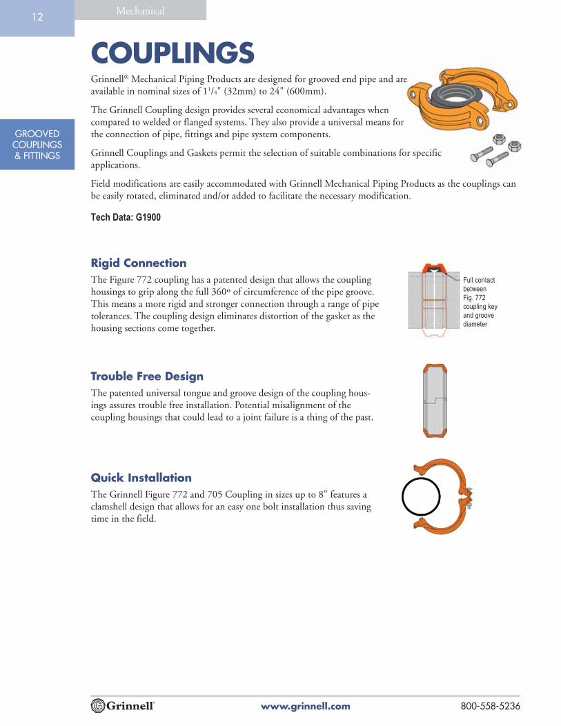
Grinnell® Mechanical Piping Products are designed for grooved end pipe and areavailable in nominal sizes of 11/4" (32mm) to 24" (600mm).
The Grinnell Coupling design provides several economical advantages whencompared to welded or flanged systems. They also provide a universal means forthe connection of pipe, fittings and pipe system components.
Grinnell Couplings and Gaskets permit the selection of suitable combinations for specificapplications.
Field modifications are easily accommodated with Grinnell Mechanical Piping Products as the couplings canbe easily rotated, eliminated and/or added to facilitate the necessary modification.
Rigid ConnectionThe Figure 772 coupling has a patented design that allows the couplinghousings to grip along the full 360º of circumference of the pipe groove.This means a more rigid and stronger connection through a range of pipetolerances. The coupling design eliminates distortion of the gasket as thehousing sections come together.
Trouble Free DesignThe patented universal tongue and groove design of the coupling hous-ings assures trouble free installation. Potential misalignment of thecoupling housings that could lead to a joint failure is a thing of the past.
Quick InstallationThe Grinnell Figure 772 and 705 Coupling in sizes up to 8" features aclamshell design that allows for an easy one bolt installation thus savingtime in the field.
Full contact
between
Fig. 772
coupling key
and groove
diameter
Tech Data: G1900

COUPLINGS
www.grinnell.com800-558-5236
GROOVEDCOUPLINGS& FITTINGS
Mechanical13
MATERIAL SPECIFICATIONSThe applicable material specifications for ductile iron, galvanizing and rubber gaskets apply:
Ductile Iron Housing Specifications• ASTM A-536 - Standard Specification for
Ductile Iron Castings Grade 65-45-12• Tensile Strength, minimum psi-65,000
(MPa-448)• Yield Strength, minimum psi-45,000
(MPa-310)• Elongation in 2" (50mm), minimum 12%• ASTM A-153 - Standard Specification for Hot
Dip Galvanizing
Bolt / Nut SpecificationsCarbon steel oval neck bolts and nuts are heattreated and conform to the physical properties ofASTM A-183 with a minimum tensile strength of110,000psi (758,422 kPa). Bolts and nuts are Zincelectroplated to ASTM B633.
Gold color coded metric bolts conforming to thephysical properties of ASTM F568M are availableupon request. Contact Tyco Fire & BuildingProducts.
Gasket SpecificationsGrade “E” EPDM gaskets have a green color codeidentification and conform to ASTMD-2000 for service temperatures from -30°F(-34°C) to 230°F (110°C). They are recommendedfor hot water not to exceed 230°F (110°C), plus avariety of dilute acids, oil free air and many chemi-cal services. They are not recommended for petro-leum services. For low temperature and vacuumsystems, a Tri-Seal Grade “E” EPDM gasket withrigid coupling is recommended.
Grade “T” Nitrile gaskets have an orange colorcode identification and conform to ASTMD-2000 for service temperatures from -20°F(-29°C) to 180°F (82°C). They are recommendedfor petroleum products, vegetable oils, mineral oils,and air with oil vapors.
Grade “L” Silicone gaskets are red and conform toASTM D-2000 for service -30ºF (-34ºC) to 350ºF(+177ºC). They are recommended for air withouthydrocarbons, dry heat.
Grade “O” Fluoroelastomer gaskets have a bluecolor code and conform to ASTM D-2000 forservice +20ºF (-7ºC) to +300ºF (+149ºC). They arerecommended for oxidizing acids, petroleumproducts, hydraulici fluids, lubricants, halogenatedhyrdrocarbons.
Grade “EN” NSF 61 approved gaskets have acopper color code and are for potable water systemsup to +180ºF (+82ºC). Not recommended forpetroleum service.
Coatings• Orange - non lead (standard)• RAL Red - non lead (optional)• Hot Dipped Zinc Galvanized (optional)• Copper acrylic enamel
COUPLINGS
www.grinnell.com 800-558-5236
GROOVEDCOUPLINGS& FITTINGS
Mechanical14
Nominal Pipe Max.† Max. End† Max. End*‡ Nominal Dimensions Coupling Bolts Approx.Size OD Pressures Load Gap A B C Size** Weight
Inches Inches psi Lbs. Inches Inches Inches Inches Qty Inches Lbs.DN mm Bar kN mm mm mm mm mm Kg
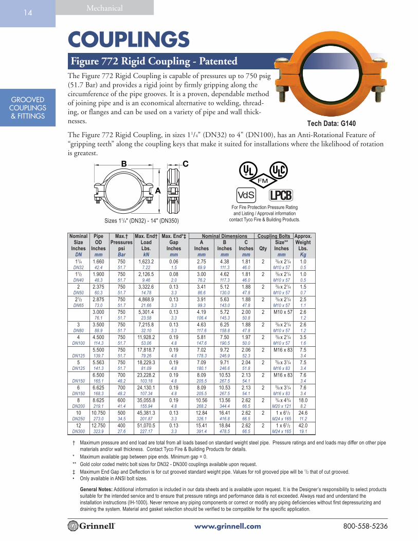
Figure 772 Rigid Coupling - Patented
† Maximum pressure and end load are total from all loads based on standard weight steel pipe. Pressure ratings and end loads may differ on other pipe
materials and/or wall thickness. Contact Tyco Fire & Building Products for details.
* Maximum available gap between pipe ends. Minimum gap = 0.
** Gold color coded metric bolt sizes for DN32 - DN300 couplings available upon request.
‡ Maximum End Gap and Deflection is for cut grooved standard weight pipe. Values for roll grooved pipe will be 1/2 that of cut grooved.
• Only available in ANSI bolt sizes.
The Figure 772 Rigid Coupling is capable of pressures up to 750 psig(51.7 Bar) and provides a rigid joint by firmly gripping along thecircumference of the pipe grooves. It is a proven, dependable methodof joining pipe and is an economical alternative to welding, thread-ing, or flanges and can be used on a variety of pipe and wall thick-nesses.
The Figure 772 Rigid Coupling, in sizes 11/4" (DN32) to 4" (DN100), has an Anti-Rotational Feature of“gripping teeth” along the coupling keys that make it suited for installations where the likelihood of rotationis greatest.
For Fire Protection Pressure Rating
and Listing / Approval information
contact Tyco Fire & Building Products.
LPCBVd S
11/4 1.660 750 1,623.2 0.06 2.75 4.38 1.81 2 3/8 x 21/4 1.0DN32 42.4 51.7 7.22 1.5 69.9 111.3 46.0 M10 x 57 0.5
11/2 1.900 750 2,126.5 0.08 3.00 4.62 1.81 2 3/8 x 21/4 1.0DN40 48.3 51.7 9.46 2.0 76.2 117.3 46.0 M10 x 57 0.5
2 2.375 750 3,322.6 0.13 3.41 5.12 1.88 2 3/8 x 21/4 1.5DN50 60.3 51.7 14.78 3.3 86.6 130.0 47.8 M10 x 57 0.7
21/2 2.875 750 4,868.9 0.13 3.91 5.63 1.88 2 3/8 x 21/4 2.5DN65 73.0 51.7 21.66 3.3 99.3 143.0 47.8 M10 x 57 1.1
3.000 750 5,301.4 0.13 4.19 5.72 2.00 2 M10 x 57 2.676.1 51.7 23.58 3.3 106.4 145.3 50.8 1.2
3 3.500 750 7,215.8 0.13 4.63 6.25 1.88 2 3/8 x 21/4 2.6DN80 88.9 51.7 32.10 3.3 117.6 158.8 47.8 M10 x 57 1.2
4 4.500 750 11,928.2 0.19 5.81 7.50 1.97 2 3/8 x 21/4 3.5DN100 114.3 51.7 53.06 4.8 147.6 190.5 50.0 M10 x 57 1.6
5.500 750 17,818.7 0.19 7.02 9.72 2.06 2 M16 x 83 7.5DN125 139.7 51.7 79.26 4.8 178.3 246.9 52.3 3.4
5 5.563 750 18,229.3 0.19 7.09 9.71 2.04 2 5/8 x 31/4 7.5DN125 141.3 51.7 81.09 4.8 180.1 246.6 51.8 M16 x 83 3.4
6.500 700 23,228.2 0.19 8.09 10.53 2.13 2 M16 x 83 7.6DN150 165.1 48.2 103.18 4.8 205.5 267.5 54.1 3.4
6 6.625 700 24,130.1 0.19 8.09 10.53 2.13 2 5/8 x 31/4 7.6DN150 168.3 48.2 107.34 4.8 205.5 267.5 54.1 M16 x 83 3.4
8 8.625 600 35,055.8 0.19 10.56 13.56 2.62 2 3/4 x 43/4 18.0DN200 219.1 41.4 155.94 4.8 268.2 344.4 66.5 M20 x 121 8.2
10 10.750 500 45,381.3 0.13 12.84 16.41 2.62 2 1 x 61/2 24.6DN250 273.0 34.5 201.87 3.3 326.1 416.8 66.5 M24 x 165 11.2
12 12.750 400 51,070.5 0.13 15.41 18.84 2.62 2 1 x 61/2 42.0DN300 323.9 27.6 227.17 3.3 391.4 478.5 66.5 M24 x 165 19.1
Tech Data: G140
A
B C
Sizes 11/4" (DN32) - 14" (DN350)
General Notes: Additional information is included in our data sheets and is available upon request. It is the Designer’s responsibility to select products
suitable for the intended service and to ensure that pressure ratings and performance data is not exceeded. Always read and understand the
installation instructions (IH-1000). Never remove any piping components or correct or modify any piping deficiencies without first depressurizing and
draining the system. Material and gasket selection should be verified to be compatible for the specific application.

COUPLINGS
www.grinnell.com800-558-5236
GROOVEDCOUPLINGS& FITTINGS
Mechanical15
Figure 772 Rigid Coupling - Patented
Nominal Pipe Max.† Max. End† Max. End*‡ Nominal Dimensions Coupling Bolts Approx.Size OD Pressures Load Gap A B C Size Weight
Inches Inches psi Lbs. Inches Inches Inches Inches Qty Inches Lbs.DN mm Bar kN mm mm mm mm mm Kg
14 14.000 300 46,181.4 0.13 16.68 20.38 2.93 2 1 x 51/2• 48.0DN350 355,6 20,7 205,43 3,3 423,7 517,6 74,4 21,7
16 16.000 300 60,318.6 0.13 18.50 22.64 2.93 3 1 x 51/2• 52.1DN400 406,4 20,7 268,31 3,3 469,9 575,1 74,4 23,6
18 18.000 300 76,340.7 0.25 21.31 25.12 3.06 3 1 x 51/2• 52.1DN450 457,2 20,7 339,58 6,4 541,3 638,0 77,7 30,8
20 20.000 300 94,247.8 0.25 23.50 27.88 3.06 4 11/8 x 53/4• 89.0DN500 508,0 20,7 419,23 6,4 596,9 708,2 77,7 40,4
24 24.000 250 113,097.3 0.25 27.63 32.00 3.19 4 11/8 x 53/4• 96.0DN600 609,6 17,2 503,08 6,4 701,8 812,8 81,0 43,5
† Maximum pressure and end load are total from all loads based on standard weight steel pipe. Pressure ratings and
end loads may differ on other pipe materials and/or wall thickness. Contact Tyco Fire & Building Products for
details.
* Maximum available gap between pipe ends. Minimum gap = 0.
** Gold color coded metric bolt sizes for DN32 - DN300 couplings available upon request.
‡ Maximum End Gap and Deflection is for cut grooved standard weight pipe. Values for roll grooved pipe will be 1/2
that of cut grooved.
• Only available in ANSI bolt sizes.
Please refer to General Notes on page 14.
Tech Data: G140
Sizes 16" (DN400) - 18" (DN450) Sizes 20" (DN500) - 24" (DN600)
A A
B BC C
14 A

COUPLINGS
www.grinnell.com800-558-5236
GROOVEDCOUPLINGS& FITTINGS
Mechanical15
Nominal Pipe Max.† Max. End† Max. End*‡ Deflection ‡ Nominal Dimensions Coupling Bolts Approx.Size OD Pressures Load Gap Degrees Inches/ A B C Size Weight
Inches Inches psi Lbs. Inches Per Foot Inches Inches Inches Qty Inches Lbs.mm mm Bar kN mm Coupling mm/m mm mm mm mm Kg
Figure 705 Flexible Coupling
11/4 1.660 500 1,082.1 0.13 4°19' 0.90 2.56 4.19 1.81 2 3/8 x 21/4 1.532 42.4 34.5 4.81 3.3 75.0 65.0 106.4 46.0 M10 x 57 0.7
11/2 1.900 500 1,417.6 0.13 3°46' 0.79 2.75 4.44 1.81 2 3/8 x 21/4 1.640 48.3 34.5 6.30 3.3 65.8 69.9 112.8 46.0 M10 x 57 0.7
2 2.375 500 2,215.1 0.13 3°1' 0.63 3.25 4.88 1.88 2 3/8 x 21/4 1.750 60.3 34.5 9.85 3.3 52.5 82.6 124.0 47.8 M10 x 57 0.8
21/2 2.875 500 3,245.9 0.13 2°29' 0.52 3.69 5.50 1.88 2 3/8 x 21/4 2.065 73.0 34.5 14.43 3.3 43.3 93.7 139.7 47.8 M10 x 57 0.9
3.000 500 3,534.3 0.13 2°23' 0.50 4.00 5.75 1.88 2 M12 x 76 3.176.1 34.5 15.72 3.3 41.7 101.6 146.1 47.8 1.4
3 3.500 500 4,810.6 0.13 2°3' 0.43 4.38 6.50 1.88 2 1/2 x 3 3.180 88.9 34.5 21.39 3.3 35.8 111.3 165.1 47.8 M12 x 76 1.4
4.250 500 7,093.1 0.25 3°22' 0.70 5.50 7.50 2.06 2 M12 x 76 4.2108.0 34.5 31.55 6.4 58.3 139.7 190.5 52.3 1.9
4 4.500 500 7,952.2 0.25 3°11' 0.67 5.69 7.75 2.06 2 1/2 x 3 4.0100 114.3 34.5 35.35 6.4 55.8 144.5 196.9 52.3 M12 x 76 1.8
5.250 450 9,741.4 0.25 2°44' 0.56 6.56 9.50 2.06 2 M16 x 83 7.2133.0 31.0 43.33 6.4 46.7 166.6 241.3 52.3 3.3
5.500 450 10,691.2 0.25 2°36' 0.55 6.81 9.75 2.06 2 M16 x 83 7.2139.7 31.0 47.56 6.4 45.5 173.0 247.7 52.3 3.3
5 5.563 450 10,937.6 0.25 2°35' 0.54 6.88 9.75 2.06 2 5/8 x 31/4 7.1125 141.3 31.0 48.63 6.4 45.0 174.8 247.7 52.3 M16 x 83 3.2
6.250 450 13,805.8 0.25 2°17' 0.48 7.56 10.31 2.06 2 M16 x 83 7.4159.0 31.0 61.41 6.4 40.0 192.0 261.9 52.3 3.4
6.500 450 14,932.4 0.25 2°12' 0.46 7.75 10.69 2.06 2 M16 x 83 7.1165.1 31.0 66.36 6.4 38.3 196.9 271.5 52.3 3.2
6 6.625 450 15,512.2 0.25 2°10' 0.45 7.94 10.69 2.06 2 5/8 x 31/4 7.1150 168.3 31.0 68.97 6.4 37.5 201.7 271.5 52.3 M16 x 83 3.2
8.500 450 25,535.3 0.25 1°40' 0.35 10.07 13.50 2.31 2 M20 x 121 12.4216.3 31.0 113.59 6.4 29.2 255.8 342.9 58.7 5.6
8 8.625 450 26,291.8 0.25 1°40' 0.35 10.19 13.56 2.50 2 3/4 x 43/4 14.5200 219.1 31.0 116.89 6.4 29.2 258.8 344.4 63.5 M20 x 121 6.6
10 10.750 350 31,766.9 0.25 1°20' 0.28 12.69 16.38 2.63 2 1 x 61/2 28.0250 273.0 24.1 141.31 6.4 23.3 322.3 416.1 66.8 M24 x 165 12.7
12 12.750 350 44,686.7 0.25 1°7' 0.23 14.94 18.88 2.63 2 1 x 61/2 36.5300 323.9 24.1 198.78 6.4 19.2 379.5 479.6 66.8 M24 x 165 16.6
† Maximum pressure and end load are total from all loads based on standard weight steel pipe. Pressure ratings and end loads may
differ on other pipe materials and/or wall thickness. Contact Tyco Fire & Building Products for details.
* Maximum available gap between pipe ends. minimum gap = 0.
‡ Maximum end gap and deflection are for cut grooved standard weight pipe. Values for roll grooved pipe will be 1/2 that of cut
grooved.
Please refer to General Notes on page 14.
B
A
C
The Figure 705 Flexible Coupling is capable of pressures up to 500psig (34.5 Bar) depending on pipe size and wall thickness. It providesa dependable method of joining pipe and is suitable for use in avariety of applications.
For Fire Protection Pressure Rating
and Listing / Approval information
contact Tyco Fire & Building Products.
LPCBVd S
Tech Data: G110

COUPLINGS
www.grinnell.com 800-558-5236
GROOVEDCOUPLINGS& FITTINGS
Mechanical16
Nominal Pipe Max.† Max. End† Max. End*‡ Deflection ‡ Nominal Dimensions Coupling Bolts Approx.Size OD Pressures Load Gap Degrees Inches/ A B C Size Weight
Inches Inches psi Lbs. Inches Per Foot Inches Inches Inches Qty Inches Lbs.mm mm Bar kN mm Coupling mm/m mm mm mm mm Kg
Figure 707 Heavy Duty Flexible Coupling
B
A
C
A
BC
A
BC
Sizes 11/2" (40mm) - 12" (300mm) Sizes 14" (350mm) - 18" (450mm) Sizes 20" (500mm) - 24" (600mm)
The Figure 707 Heavy Duty Flexible Coupling is capable of pressuresup to 1000 psig (69 Bar) depending on pipe size and wall thickness. Itprovides a dependable method of joining pipe and is suitable for use ina variety of applications. Flexible couplings can act as an “expansionjoint” allowing linear and angular movement of the pipes whenproperly installed.
For Fire Protection Pressure Rating
and Listing / Approval information
contact Tyco Fire & Building Products.
LPCBVd S
† Maximum pressure and end load are total from all loads based on standard weight steel pipe. Pressure ratings and end loads may
differ on other pipe materials and/or wall thickness. Contact Tyco Fire & Building Products for details.
* Maximum available gap between pipe ends. minimum gap = 0.
‡ Maximum end gap and deflection are for cut grooved standard weight pipe. Values for roll grooved pipe will be 1/2 that of cut grooved.
** Only available in ANSI bolt sizes.
Please refer to General Notes on page 14.
1 1.315 1000 1,360.0 0.13 5°26' 1.14 2.38 4.00 1.81 2 1/2 x 3 2.025 33.7 69.0 6.10 3.3 98.4 60.5 101.6 46.0 M12 x 76 0.9
11/2 1.900 1000 2,835.3 0.13 3°46' 0.79 2.97 4.63 1.81 2 1/2 x 3 2.540 48.3 69.0 12.61 3.3 65.8 75.4 117.6 46.0 M12 x 76 1.1
2 2.375 1000 4,430.1 0.13 3°1' 0.63 3.54 5.25 1.88 2 1/2 x 3 3.050 60.3 69.0 19.71 3.3 52.5 89.9 133.4 47.8 M12 x 76 1.4
21/2 2.875 1000 6,491.8 0.13 2°29' 0.52 4.06 5.75 1.88 2 1/2 x 3 3.565 73.0 69.0 28.88 3.3 43.3 103.1 146.1 47.8 M12 x 76 1.6
3.000 1000 7,068.6 0.13 2°23' 0.50 4.19 5.75 1.88 2 M12 x 76 3.776.1 69.0 31.44 3.3 41.7 106.4 146.1 47.8 1.7
3 3.500 1000 9,621.1 0.13 2°3' 0.43 4.69 6.38 1.88 2 1/2 x 3 4.080 88.9 69.0 42.80 3.3 35.8 119.1 162.1 47.8 M12 x 76 1.8
4 4.500 1000 15,904.3 0.25 3°11' 0.67 5.95 8.25 2.06 2 5/8 x 31/4 7.0100 114.3 69.0 70.75 6.4 55.8 151.1 209.6 52.3 M16 x 83 3.2
5 5.563 1000 24,305.7 0.25 2°35' 0.54 7.08 10.00 2.06 2 3/4 x 43/4 10.5125 141.3 69.0 108.12 6.4 45.0 179.8 254.0 52.3 M20 x 121 4.8
6.500 1000 33,183.1 0.25 2°12' 0.46 8.19 11.25 2.06 2 M20 x 121 12.5165.1 69.0 147.61 6.4 38.3 208.0 285.8 52.3 5.7
6 6.625 1000 34,471.6 0.25 2°10' 0.45 8.30 11.25 2.06 2 3/4 x 43/4 12.5150 168.3 69.0 153.34 6.4 37.5 210.8 285.8 52.3 M20 x 121 5.7
8 8.625 800 46,741.0 0.25 1°40' 0.35 10.68 14.00 2.47 2 7/8 x 61/2 23.5200 219.1 55.1 207.91 6.4 29.2 271.3 355.6 62.7 M22 x 165 10.7
10 10.750 800 72,610.1 0.25 1°20' 0.28 13.06 16.44 2.63 2 1 x 61/2 33.0250 273.0 55.1 322.99 6.4 23.3 331.7 417.6 66.8 M24 x 165 15.0
12 12.750 800 102,141.0 0.25 1°7' 0.23 15.39 18.84 2.63 2 1 x 61/2 37.0300 323.9 55.1 454.35 6.4 19.2 390.9 478.5 66.8 M24 x165 16.8
14 14.000 300 46,181.4 0.25 1°2' 0.22 16.67 20.38 2.94 2 1 x 51/2** 44.0350 355.6 20.7 205.43 6.4 18.3 423.4 517.7 74.7 20.0
16 16.000 300 60,318.6 0.25 0°54' 0.19 18.83 22.64 2.94 2 1 x 51/2** 52.1400 406.4 20.7 268.31 6.4 15.8 478.3 575.1 74.7 23.6
18 18.000 300 76,340.7 0.25 0°48' 0.17 21.31 25.12 3.06 2 1 x 51/2** 68.0450 457.2 20.7 339.58 6.4 14.2 541.3 638.0 77.7 30.8
20 20.000 300 94,247.8 0.25 0°43' 0.15 23.47 27.88 3.06 2 11/8 x 53/4** 89.0500 508.0 20.7 419.23 6.4 12.5 596.1 708.2 77.7 40.4
24 24.000 250 113,097.3 0.25 0°36' 0.13 27.58 32.00 3.19 2 11/8 x 53/4** 96.0600 609.6 17.2 503.08 6.4 10.8 700.5 812.8 81.0 43.5
Tech Data: G130

COUPLINGS
www.grinnell.com800-558-5236
GROOVEDCOUPLINGS& FITTINGS
Mechanical17
Nominal Pipe Max.† Max. End† Max. End*‡ Deflection ‡ Nominal Dimensions Coupling Bolts Approx.Size OD Pressures Load Gap Degrees Inches/ A B C Size Weight
Inches Inches psi Lbs. Inches Per Foot Inches Inches Inches Qty Inches Lbs.mm mm Bar kN mm Coupling mm/m mm mm mm mm Kg
2 x 11/2 2.375 x 1.900 500 1,417.6 0.13 1°53' 0.39 3.50 5.06 1.88 2 3/8 x 21/4 2.050 x 40 60.3 x 48.3 34.5 6.31 3.3 32.5 88.9 128.5 47.8 M10 x 57 0.9
21/2 x 2 2.875 x 2.375 500 2,215.1 0.13 1°33' 0.32 4.00 5.50 1.88 2 3/8 x 21/4 2.565 x 50 73.0 x 60.3 34.5 9.85 3.3 26.7 101.6 139.7 47.8 M10 x 57 1.1
3.000 x 2.375 500 2,215.1 0.13 1°34' 0.32 4.19 5.88 1.88 2 M12 x 76 3.176.1 x 60.3 34.5 9.85 3.3 26.7 106.4 149.4 47.8 1.4
3 x 2 3.500 x 2.375 500 2,215.1 0.13 1°17' 0.27 4.69 6.50 1.88 2 1/2 x 3 4.580 x 50 88.9 x 60.3 34.5 9.85 3.3 22.5 119.1 165.1 47.8 M12 x 76 2.0
3 x 21/2 3.500 x 2.875 500 3,245.9 0.13 1°17' 0.27 4.69 6.50 1.88 2 1/2 x 3 4.680 x 65 88.9 x 73.0 34.5 14.44 3.3 22.5 119.1 165.1 47.8 M12 x 76 2.1
3.500 x 3.000 500 3,534.3 0.13 1°17' 0.27 4.69 6.50 1.88 2 M12 x 76 4.588.9 x 76.1 34.5 15.72 3.3 22.5 119.1 165.1 47.8 2.0
4 x 2 4.500 x 2.375 500 2,215.1 0.19 2°38' 0.55 6.00 8.13 2.00 2 5/8 x 31/4 7.0100 x 60 114.3 x 60.3 34.5 9.85 4.8 45.8 152.4 206.5 50.8 M16 x 83 3.2
4 x 21/2 4.500 x 2.875 500 3,245.9 0.19 2°38' 0.55 6.00 8.13 2.00 2 5/8 x 31/4 6.1100 x 65 114.3 x 73.0 34.5 14.44 4.8 45.8 152.4 206.5 50.8 M16 x 83 2.8
4.500 x 3.000 500 3,534.3 0.19 2°38' 0.55 6.00 8.13 2.00 2 M16 x 83 6.2114.3 x 76.1 34.5 15.72 4.8 45.8 152.4 206.5 50.8 2.8
4 x 3 4.500 x 3.500 500 4,810.6 0.19 2°38' 0.55 6.00 8.13 2.00 2 5/8 x 31/4 6.2100 x 80 114.3 x 88.9 34.5 21.40 4.8 45.8 152.4 206.5 50.8 M16 x 83 2.8
5.500 x 4.500 500 7,952.2 0.25 2°38' 0.55 7.06 9.50 2.06 2 M20 x 121 11.0139.7 x 114.3 34.5 35.37 6.4 45.8 179.3 241.3 52.3 5.0
5 x 4 5.563 x 4.500 500 7,952.2 0.25 2°5' 0.44 7.13 9.56 2.06 2 3/4 x 43/4 10.1125 x 100 141.3 x 114.3 34.5 35.37 6.4 36.7 181.1 242.8 52.3 M20 x 121 4.6
6.500 x 4.500 400 6,361.7 0.25 1°50' 0.38 8.18 10.81 2.06 2 M20 x 121 12.5165.1 x 114.3 27.6 28.30 6.4 31.7 207.8 274.6 52.3 5.7
6 x 4 6.625 x 4.500 400 6,361.7 0.25 1°44' 0.36 8.38 10.88 2.06 2 3/4 x 43/4 12.5150 x 100 168.3 x 114.3 27.6 28.30 6.4 30.0 212.9 276.4 52.3 M20 x 121 5.7
6 x 5 6.625 x 5.563 400 9,722.3 0.25 1°44' 0.36 8.38 10.88 2.06 2 3/4 x 43/4 11.7150 x 125 168.3 x 141.3 27.6 43.25 6.4 30.0 212.9 276.4 52.3 M20 x 121 5.3
8 x 6 8.625 x 6.625 400 13,788.6 0.25 1°15' 0.26 10.69 13.75 2.25 2 7/8 x 61/2 23.5200 x 150 219.1 x 168.3 27.6 61.33 6.4 21.7 271.5 349.3 57.2 M22 x 165 10.7
Figure 716 Flexible Reducing Coupling
† Maximum pressure and end load are total from all loads based on standard weight steel pipe. Pressure ratings and end loads may differ
on other pipe materials and/or wall thickness. Contact Tyco Fire & Building Products for details.
* Maximum available gap between pipe ends. minimum gap = 0.
‡ Maximum end gap and deflection are for cut grooved standard weight pipe. Values for roll grooved pipe will be 1/2 that of cut grooved.
Please refer to General Notes on page 14.
B
A
C
The Figure 716 Reducing Coupling is capable of pressures up to 500psig (34.5 Bar) depending on pipe size and wall thickness. It providesa direct transition between two different pipe sizes, replacing twocouplings and a reducing fitting.
For Fire Protection Pressure Rating
and Listing / Approval information
contact Tyco Fire & Building Products.
LPCBVd S
Tech Data: G120

FLANGES
www.grinnell.com 800-558-5236
GROOVEDCOUPLINGS& FITTINGS
Mechanical18
Figure 71 Flange Adapter (ANSI Class 125/150)The Figure 71 Flange Adapter is capable of pressures up to 300 psig(20.7 Bar) depending on pipe size and wall thickness. It provides adirect transition from flanged components into a grooved piping system.I.P.S. size flange bolt patterns conform to ANSI Class 125 and 150.
The gasket seal is designed with optimum amount of rubber to providea dependable seal and also avoid the overfilling of the gasket pocketwhich may cause assembly difficulties.
B E DF
A C
† Maximum pressure and end load are total from all loads based on standard weight steel pipe. Pressure ratings and
end loads may differ on other pipe materials and/or wall thickness. Contact Tyco Fire & Building Products for
details.
* Dimensions D and E represent minimum and maximum sealing surfaces.
** Bolts are not supplied. Bolt lengths shown are standard; it is the responsibility of the purchaser to verify correct
length for the intended application.
Note: Metal flange washer adapters are required when the Figure 71 Flange Adapter is used against surfaces such as:
• Rubber surfaces
• Adapting to AWWA cast flanges
• Rubber faced wafer valves
• Serrated flange surfaces
Figure 71 Flange Adapters are not recommended for applications which incorporate tie rods for anchoring or on a
standard fitting within 90° of each other. Contact Tyco Fire & Building Products for recommendations prior to using
with plastic pipe.
Please refer to General Notes on page 14.
Nominal Pipe Max.† Max. End† Nominal Dimensions Bolts** Approx.Size OD Pressures Load A B C D* E* F Size Weight
Inches Inches psi Lbs. Inches Inches Inches Inches Inches Inches Qty Inches Lbs.mm mm Bar kN mm mm mm mm mm mm mm Kg
2 2.375 300 1,329.0 6.38 4.75 0.75 2.38 3.41 7.25 4 5/8 x 3 3.050 60.3 20.7 5.91 162.1 120.7 19.1 60.5 86.6 184.2 1.4
21/2 2.875 300 1,947.5 7.00 5.50 0.88 2.88 3.91 7.88 4 5/8 x 3 5.065 73.0 20.7 8.66 178.0 140.0 22.0 73.0 99.0 200.0 2.3
3 3.500 300 2,886.3 7.50 6.00 0.94 3.50 4.53 9.88 4 5/8 x 3 5.680 88.9 20.7 12.84 190.5 152.4 23.9 88.9 115.1 251.0 2.5
4 4.500 300 4,771.3 9.00 7.50 0.94 4.50 5.53 9.90 8 5/8 x 3 7.0100 114.3 20.7 21.22 228.6 190.5 23.9 114.3 140.5 251.5 3.2
5 5.563 300 7,291.7 10.00 8.50 1.00 5.56 6.72 11.38 8 3/4 x 31/2 9.2125 141.3 20.7 32.44 254.0 215.9 25.4 141.2 170.7 289.1 4.2
6 6.625 300 10,341.5 11.00 9.50 1.00 6.62 7.78 11.88 8 3/4 x 31/2 10.0150 168.3 20.7 46.02 279.4 241.3 25.4 168.1 197.6 301.8 4.5
8 8.625 300 17,527.9 13.50 11.75 1.13 8.62 9.94 14.36 8 3/4 x 31/2 16.6200 219.1 20.7 77.99 342.9 298.5 28.7 218.9 252.5 365.3 7.5
10 10.750 300 27,228.8 16.00 14.25 1.19 10.75 12.31 16.88 12 7/8 x 4 21.8250 273.0 20.7 121.08 406.4 362.0 30.2 273.1 312.7 428.8 9.9
12 12.750 300 38,302.9 19.00 17.00 1.25 12.75 14.31 20.00 12 7/8 x 4 24.2300 323.9 20.7 170.44 482.6 431.8 31.8 323.9 363.9 508.0 11.0
For Fire Protection Pressure Rating
and Listing / Approval information
contact Tyco Fire & Building Products.
LPCBVd S
Tech Data: G150

FLANGES
www.grinnell.com800-558-5236
GROOVEDCOUPLINGS& FITTINGS
Mechanical19
Flange Washer Adapter
* DIN
† DIN and ANSI
‡ ANSI
Note: Metal flange washer adapters are required when the Figure 71
Flange Adapter is used against surfaces such as:
• Rubber surfaces
• Adapting to AWWA cast flanges
• Rubber faced wafer valves
• Serrated flange surfaces
Please refer to General Notes on page 14.
Nominal Pipe Nominal DimensionsSize OD A B
Inches Inches Inches Inches
mm mm mm mm
†2 2.375 3.94 2.7550 60.3 100.0 57.2
‡21/2 2.875 4.69 2.7565 73.0 119.1 69.9
* 3.000 4.89 2.8876.1 124.2 73.2
‡ 3.500 5.19 3.3888.9 131.8 85.9
*3 3.500 5.48 3.3880 88.9 139.2 85.9
‡4 4.500 6.69 4.38100 114.3 169.9 111.3
*4 4.500 6.27 4.38100 114.3 159.3 111.3
‡5 5.563 7.56 5.38125 141.3 192.0 136.7
* 5.500 7.45 5.32139.7 189.2 135.1
* 6.500 8.47 6.32165.1 215.1 160.5
†6 6.625 8.56 6.44150 168.3 217.4 163.6
‡8 8.625 10.81 8.44200 219.1 274.6 214.4
*8 8.625 10.64 8.44200 219.1 270.3 214.4
‡10 10.750 13.19 10.50250 273.0 335.0 266.7
*10 10.750 12.85 10.50250 273.0 326.4 266.7
‡12 12.750 15.94 12.50300 323.9 404.9 317.5
*12 12.750 15.01 12.50300 323.9 381.3 317.5
AA
B
Material: Stainless Steel ASTM A666 Type 304-2B
COUPLINGS
www.grinnell.com 800-558-5236
GROOVEDCOUPLINGS& FITTINGS
Mechanical22
Nominal Pipe Max.† Max. End† Max. End*‡ Nominal Dimensions Coupling Bolts Approx.Size OD Pressures Load Gap A B C Size** Weight
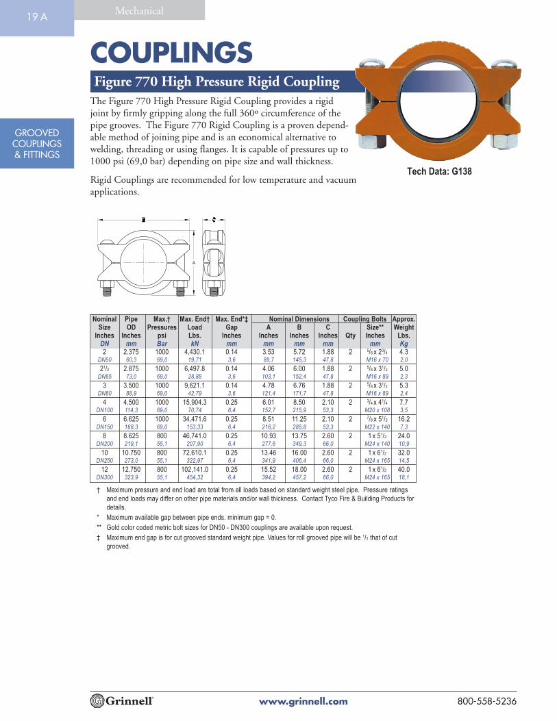
Inches Inches psi Lbs. Inches Inches Inches Inches Qty Inches Lbs.DN mm Bar kN mm mm mm mm mm Kg2 2.375 1000 4,430.1 0.14 3.53 5.72 1.88 2 5/8 x 23/4 4.3
DN50 60,3 69,0 19,71 3,6 89,7 145,3 47,8 M16 x 70 2,0
21/2 2.875 1000 6,497.8 0.14 4.06 6.00 1.88 2 5/8 x 31/2 5.0DN65 73,0 69,0 28,88 3,6 103,1 152,4 47,8 M16 x 89 2,3
3 3.500 1000 9,621.1 0.14 4.78 6.76 1.88 2 5/8 x 31/2 5.3DN80 88,9 69,0 42,79 3,6 121,4 171,7 47,8 M16 x 89 2,4
4 4.500 1000 15,904.3 0.25 6.01 8.50 2.10 2 3/4 x 41/4 7.7DN100 114,3 69,0 70,74 6,4 152,7 215,9 53,3 M20 x 108 3,5
6 6.625 1000 34,471.6 0.25 8.51 11.25 2.10 2 7/8 x 51/2 16.2DN150 168,3 69,0 153,33 6,4 216,2 285,8 53,3 M22 x 140 7,3
8 8.625 800 46,741.0 0.25 10.93 13.75 2.60 2 1 x 51/2 24.0DN200 219,1 55,1 207,90 6,4 277,6 349,3 66,0 M24 x 140 10,9
10 10.750 800 72,610.1 0.25 13.46 16.00 2.60 2 1 x 61/2 32.0DN250 273,0 55,1 322,97 6,4 341,9 406,4 66,0 M24 x 165 14,5
12 12.750 800 102,141.0 0.25 15.52 18.00 2.60 2 1 x 61/2 40.0DN300 323,9 55,1 454,32 6,4 394,2 457,2 66,0 M24 x 165 18,1
Figure 770 High Pressure Rigid Coupling
† Maximum pressure and end load are total from all loads based on standard weight steel pipe. Pressure ratings
and end loads may differ on other pipe materials and/or wall thickness. Contact Tyco Fire & Building Products for
details.
* Maximum available gap between pipe ends. minimum gap = 0.
** Gold color coded metric bolt sizes for DN50 - DN300 couplings are available upon request.
‡ Maximum end gap is for cut grooved standard weight pipe. Values for roll grooved pipe will be 1/2 that of cut
grooved.
The Figure 770 High Pressure Rigid Coupling provides a rigidjoint by firmly gripping along the full 360º circumference of thepipe grooves. The Figure 770 Rigid Coupling is a proven depend-able method of joining pipe and is an economical alternative towelding, threading or using flanges. It is capable of pressures up to1000 psi (69,0 bar) depending on pipe size and wall thickness.
Rigid Couplings are recommended for low temperature and vacuumapplications.
Tech Data: G138
19 A

FITTINGS
www.grinnell.com 800-558-5236
GROOVEDCOUPLINGS& FITTINGS
Mechanical20
Grinnell® Grooved Fittings provide an economical and efficient method of changing direction, adding anoutlet, reducing, or capping grooved piping systems.
Grinnell Grooved Fittings are rated at the pressure rating of the coupling being used.
MATERIAL SPECIFICATIONS
Ductile Iron Fitting Specifications• ASTM A-536 - Standard Specification for
Ductile Iron Castings Grade 65-45-12
• Tensile Strength, minimum psi-65,000(MPa-448)
• Yield Strength, minimum psi-45,000(MPa-310)
• Elongation in 2" (50mm), minimum 12%
• ASTM A-153 - Standard Specification for HotDip Galvanizing
Fabricated Steel Fitting Specifications• Carbon Steel: According to ASTM A-53
Grade B
• Tensile Strength, minimum psi-60,000(MPa-415)
• Yield Strength, minimum psi-35,000(MPa-240)
• Sizes 11/4" – 6" are Schedule 40
• Sizes 8" – 12" are Schedule 30
• Sizes 14" – 24" are STD (.375)
Coatings• Orange - non lead (standard)
• RAL Red - non lead (optional)
Tech Data: G180

FITTINGS
www.grinnell.com800-558-5236
GROOVEDCOUPLINGS& FITTINGS
Mechanical21
Friction Resistance(Expressed as Equivalent Straight Pipe)
Nominal Pipe Elbows Elbows Tee TeeSize OD 90° 45° Branch Run
Inches Inches Feet Feet Feet Feetmm mm Meters Meters Meters Meters11/4 1.660 1.9 1.0 4.8 1.932 42.4 0.6 0.3 1.5 0.6
11/2 1.900 2.3 1.2 5.8 2.340 48.3 0.7 0.4 1.8 0.7
2 2.375 3.2 1.6 8.0 3.250 60.3 1.0 0.5 2.5 1.0
21/2 2.875 3.9 2.0 9.8 3.965 73.0 1.2 0.6 3.0 1.2
3.000 4.1 2.1 10.3 4.176.1 1.2 0.6 3.1 1.2
3 3.500 4.9 2.4 12.2 4.980 88.9 1.5 0.7 3.7 1.5
4.250 6.5 3.3 16.3 6.5108.0 2.0 1.0 5.0 2.0
4 4.500 6.5 3.3 16.3 6.5100 114.3 2.0 1.0 5.0 2.0
5.250 8.0 4.0 20.0 8.0133.0 2.4 1.2 6.1 2.4
5.500 8.0 4.1 20.0 8.0139.7 2.4 1.3 6.1 2.4
5 5.563 8.2 4.1 20.5 8.2125 141.3 2.5 1.3 6.3 2.5
6.250 9.5 4.8 23.8 9.5159.0 2.9 1.4 7.2 2.9
6.500 9.5 4.8 23.8 9.5165.1 2.9 1.4 7.2 2.9
6 6.625 9.9 5.0 24.8 9.9150 168.3 3.0 1.5 7.6 3.0
8.500 13.1 6.6 32.8 13.1216.3 4.0 2.0 10.0 4.0
8 8.625 13.1 6.6 32.8 13.1200 219.1 4.0 2.0 10.0 4.0
10 10.750 16.5 8.3 41.3 16.5250 273.0 5.0 2.5 12.6 5.0
12 12.750 19.9 9.9 49.7 19.9300 323.9 6.1 3.0 15.1 6.1
14 14.000 23.0 18.0 67.9 23.0350 355.6 7.0 5.5 20.7 7.0
16 16.000 25.9 20.0 78.1 25.9400 406.4 7.9 6.1 23.8 7.9
18 18.000 28.9 23.0 85.0 28.9450 457.2 8.8 7.0 25.9 8.8
20 20.000 33.1 25.9 100.1 33.1500 508.0 10.1 7.9 30.5 10.1
24 24.000 40.0 29.9 115.2 40.0600 609.6 12.2 9.1 35.1 12.2
Flow Data
For the reducing tee branches, use the value that is
corresponding to the branch size. Example: For
8" x 8" x 2" (200mm x 200mm x 50mm) tee, the
branch value of 2" (50mm) is 8.0 feet (2.5 meters).
For sizes not listed, interpolate from the values shown.
Please refer to General Notes on page 14.

FITTINGS
www.grinnell.com 800-558-5236
GROOVEDCOUPLINGS& FITTINGS
Mechanical22
Figure 210 & 310 90° Elbow
FIGURE 210 CAST FIGURE 310 FABRICATED
(FULL FLOW)
Please refer to General Notes on page 14.
210 310 Fabricated
Nominal Pipe Cast Long Radius
Size OD Nominal Approx Nominal Approx
C to E Weight C to E Weight
Inches Inches Inches Lbs. Inches Lbs.
mm mm mm Kg mm Kg
11/4 1.660 2.75 1.0 3.88 1.432 42.4 69.9 0.5 98.6 0.6
11/2 1.900 2.75 1.2 4.25 1.840 48.3 69.9 0.6 108.0 0.8
2 2.375 3.25 2.0 4.38 2.550 60.3 82.6 0.9 111.3 1.1
21/2 2.875 3.75 3.0 5.75 5.065 73.0 95.3 1.4 146.1 2.3
3.000 3.75 3.0 – –76.1 95.3 1.4 – –
3 3.500 4.25 4.5 5.88 6.580 88.9 108.0 2.0 149.4 2.9
4.250 4.75 8.5 – –108.0 120.7 3.9 – –
4 4.500 5.00 8.5 7.50 11.7100 114.3 127.0 3.9 190.5 5.3
5.250 5.25 11.3 – –133.0 133.4 5.1 – –
5.500 5.50 11.3 – –139.7 139.7 5.1 – –
5 5.563 5.50 13.5 9.50 21.0125 141.3 139.7 6.1 241.3 9.5
6.250 6.00 14.6 – –159.0 152.4 6.6 – –
6.500 6.50 18.5 – –165.1 165.1 8.4 – –
6 6.625 6.50 18.5 10.75 30.0150 168.3 165.1 8.4 273.1 13.6
8.500 7.75 36.5 – –216.3 196.9 16.6 – –
8 8.625 7.75 36.5 15.00 60.0200 219.1 196.9 16.6 381.0 27.2
10 10.750 9.00 60.0 18.00 100.0250 273.0 228.6 27.2 457.2 45.4
12 12.750 10.00 67.0 21.00 140.0300 323.9 254.0 30.4 533.4 63.5
14 14.000 – – 21.00 180.0350 355.6 533.4 81.6
16 16.000 – – 24.00 220.0400 406.4 609.6 99.8
18 18.000 – – 27.00 280.0450 457.2 685.8 127.0
20 20.000 – – 32.00 350.0500 508.0 838.2 158.8
24 24.000 – – 36.00 480.0600 609.6 914.4 217.7
316 FabricatedNominal Grooved Center B Dia. Approx.
Size End OD to End H Threaded Wt. Ea.Inches Inches Inches Inches Lbsmm mm mm mm NPSC Kg6 x 4 6.625 12 21/2 11/2 38.5
150 x 100 168.3 305 64 38 17.5
6 x 5 6.625 121/2 21/2 11/2 45.4150 x 125 168.3 318 64 38 20.6
8 x 5 8.625 16 3 11/2 65.5200 x 125 219.1 406 76 38 29.7
8 x 6 8.625 16 3 11/2 73200 x 150 219.1 406 76 38 33.1
10 x 6 10.750 19 31/2 11/2 100250 x 150 273.1 483 89 38 45.4
10 x 8 10.750 19 31/2 11/2 127250 x 200 273.1 483 89 38 57.6
12 x 8 12.750 22 4 11/2 155300 x 200 323.9 559 102 38 70.3
12 x 10 12.750 22 4 11/2 186300 x 250 323.9 559 102 38 84.4
Figure 316 Reducing BaseSupport Elbow
C to E
C to E
H
B Dia.
FIGURE 316 FABRICATED
GROOVED X FLANGED

FITTINGS
www.grinnell.com800-558-5236
GROOVEDCOUPLINGS& FITTINGS
Mechanical23
Figure 201 & 301 45° Elbow
FIGURE 201 CAST
FIGURE 301 FABRICATED (FULL FLOW)
Please refer to General Notes on page 14.
201 301 FabricatedNominal Pipe Cast Long Radius
Size OD Nominal Approx Nominal ApproxC to E Weight C to E Weight
Inches Inches Inches Lbs. Inches Lbs.mm mm mm Kg mm Kg
11/4 1.660 1.75 0.9 2.50 1.132 42.4 44.5 0.4 63.5 0.5
11/2 1.900 1.75 1.1 2.50 1.340 48.3 44.5 0.5 63.5 0.6
2 2.375 2.00 1.8 2.75 1.850 60.3 50.8 0.8 69.9 0.8
21/2 2.875 2.25 2.2 3.00 2.965 73.0 57.2 1.0 76.2 1.3
3.000 2.25 2.2 – –76.1 57.2 1.0 – –
3 3.500 2.50 3.5 3.38 4.680 88.9 63.5 1.6 85.9 2.1
4.250 2.88 5.5 – –108.0 73.0 2.5 – –
4 4.500 3.00 5.2 4.00 7.5100 114.3 76.2 2.4 101.6 3.4
5.250 3.25 7.7 – –133.0 82.6 3.5 – –
5.500 3.25 7.7 – –139.7 82.6 3.5 – –
5 5.563 3.25 8.5 5.00 12.5125 141.3 82.6 3.9 127.0 5.7
6.250 3.50 12.0 – –159.0 88.9 5.4 – –
6.500 3.50 12.0 – –165.1 88.9 5.4 – –
6 6.625 3.50 12.0 5.50 12.0150 168.3 88.9 5.4 139.7 5.4
8.500 4.25 23.0 – –216.3 108.0 10.4 – –
8 8.625 4.25 23.0 7.25 34.0200 219.1 108.0 10.4 184.2 15.4
10 10.750 4.75 31.0 8.50 56.0250 273.0 120.7 14.1 215.9 25.4
12 12.750 5.25 40.0 10.00 98.0300 323.9 133.4 18.1 254.0 44.5
14 14.000 – – 8.75 105.0350 355.6 – – 228.3 47.6
16 16.000 – – 10.00 115.0400 406.4 – – 254.0 52.2
18 18.000 – – 11.25 145.0450 457.2 – – 285.8 65.8
20 20.000 – – 12.50 180.0500 508.0 – – 317.5 81.6
24 24.000 – – 15.00 250.0600 609.6 – – 381.0 113.4
FITTINGS
www.grinnell.com 800-558-5236
GROOVEDCOUPLINGS& FITTINGS
Mechanical24
FIGURE 313 FABRICATED
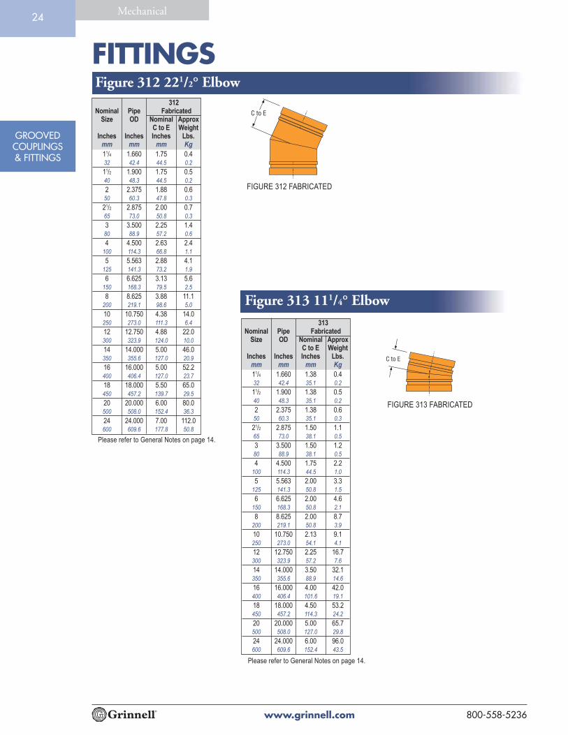
Please refer to General Notes on page 14.
313Nominal Pipe Fabricated
Size OD Nominal ApproxC to E Weight
Inches Inches Inches Lbs.mm mm mm Kg
11/4 1.660 1.38 0.432 42.4 35.1 0.2
11/2 1.900 1.38 0.540 48.3 35.1 0.2
2 2.375 1.38 0.650 60.3 35.1 0.3
21/2 2.875 1.50 1.165 73.0 38.1 0.5
3 3.500 1.50 1.280 88.9 38.1 0.5
4 4.500 1.75 2.2100 114.3 44.5 1.0
5 5.563 2.00 3.3125 141.3 50.8 1.5
6 6.625 2.00 4.6150 168.3 50.8 2.1
8 8.625 2.00 8.7200 219.1 50.8 3.9
10 10.750 2.13 9.1250 273.0 54.1 4.1
12 12.750 2.25 16.7300 323.9 57.2 7.6
14 14.000 3.50 32.1350 355.6 88.9 14.6
16 16.000 4.00 42.0400 406.4 101.6 19.1
18 18.000 4.50 53.2450 457.2 114.3 24.2
20 20.000 5.00 65.7500 508.0 127.0 29.8
24 24.000 6.00 96.0600 609.6 152.4 43.5
Figure 312 221/2° Elbow
FIGURE 312 FABRICATED
Please refer to General Notes on page 14.
312Nominal Pipe Fabricated
Size OD Nominal ApproxC to E Weight
Inches Inches Inches Lbs.mm mm mm Kg
11/4 1.660 1.75 0.432 42.4 44.5 0.2
11/2 1.900 1.75 0.540 48.3 44.5 0.2
2 2.375 1.88 0.650 60.3 47.8 0.3
21/2 2.875 2.00 0.765 73.0 50.8 0.3
3 3.500 2.25 1.480 88.9 57.2 0.6
4 4.500 2.63 2.4100 114.3 66.8 1.1
5 5.563 2.88 4.1125 141.3 73.2 1.9
6 6.625 3.13 5.6150 168.3 79.5 2.5
8 8.625 3.88 11.1200 219.1 98.6 5.0
10 10.750 4.38 14.0250 273.0 111.3 6.4
12 12.750 4.88 22.0300 323.9 124.0 10.0
14 14.000 5.00 46.0350 355.6 127.0 20.9
16 16.000 5.00 52.2400 406.4 127.0 23.7
18 18.000 5.50 65.0450 457.2 139.7 29.5
20 20.000 6.00 80.0500 508.0 152.4 36.3
24 24.000 7.00 112.0600 609.6 177.8 50.8
Figure 313 111/4° Elbow
FITTINGS
www.grinnell.com800-558-5236
GROOVEDCOUPLINGS& FITTINGS
Mechanical25
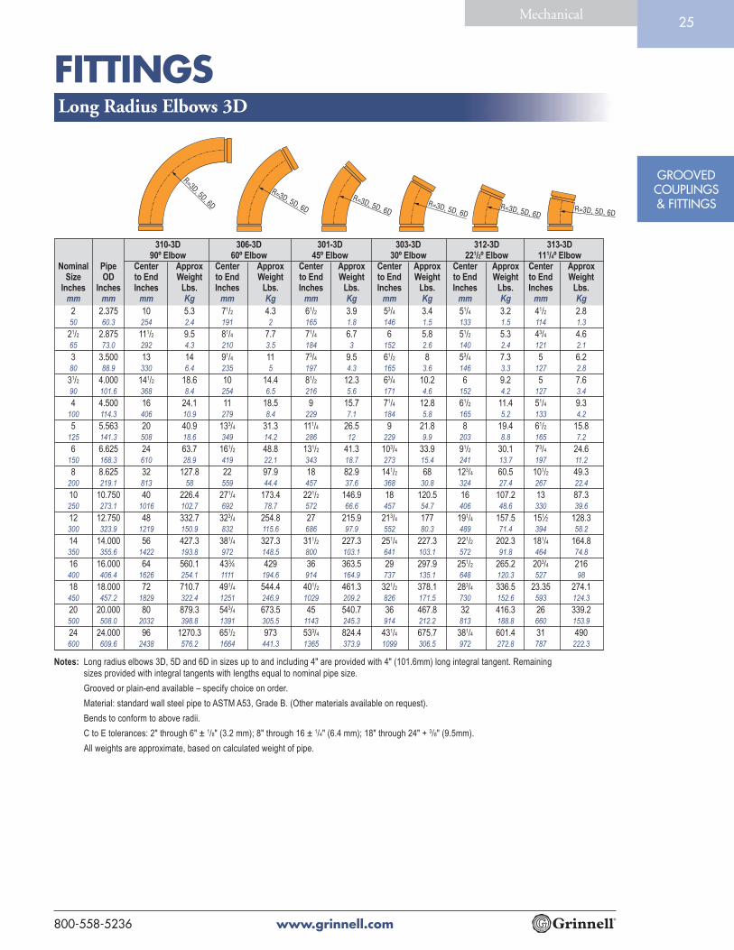
310-3D 306-3D 301-3D 303-3D 312-3D 313-3D90º Elbow 60º Elbow 45º Elbow 30º Elbow 221/2º Elbow 111/4º Elbow
Nominal Pipe Center Approx Center Approx Center Approx Center Approx Center Approx Center ApproxSize OD to End Weight to End Weight to End Weight to End Weight to End Weight to End Weight
Inches Inches Inches Lbs. Inches Lbs. Inches Lbs. Inches Lbs. Inches Lbs. Inches Lbs.mm mm mm Kg mm Kg mm Kg mm Kg mm Kg mm Kg
2 2.375 10 5.3 71/2 4.3 61/2 3.9 53/4 3.4 51/4 3.2 41/2 2.850 60.3 254 2.4 191 2 165 1.8 146 1.5 133 1.5 114 1.3
21/2 2.875 111/2 9.5 81/4 7.7 71/4 6.7 6 5.8 51/2 5.3 43/4 4.665 73.0 292 4.3 210 3.5 184 3 152 2.6 140 2.4 121 2.1
3 3.500 13 14 91/4 11 73/4 9.5 61/2 8 53/4 7.3 5 6.280 88.9 330 6.4 235 5 197 4.3 165 3.6 146 3.3 127 2.8
31/2 4.000 141/2 18.6 10 14.4 81/2 12.3 63/4 10.2 6 9.2 5 7.690 101.6 368 8.4 254 6.5 216 5.6 171 4.6 152 4.2 127 3.4
4 4.500 16 24.1 11 18.5 9 15.7 71/4 12.8 61/2 11.4 51/4 9.3100 114.3 406 10.9 279 8.4 229 7.1 184 5.8 165 5.2 133 4.2
5 5.563 20 40.9 133/4 31.3 111/4 26.5 9 21.8 8 19.4 61/2 15.8125 141.3 508 18.6 349 14.2 286 12 229 9.9 203 8.8 165 7.2
6 6.625 24 63.7 161/2 48.8 131/2 41.3 103/4 33.9 91/2 30.1 73/4 24.6150 168.3 610 28.9 419 22.1 343 18.7 273 15.4 241 13.7 197 11.2
8 8.625 32 127.8 22 97.9 18 82.9 141/2 68 123/4 60.5 101/2 49.3200 219.1 813 58 559 44.4 457 37.6 368 30.8 324 27.4 267 22.4
10 10.750 40 226.4 271/4 173.4 221/2 146.9 18 120.5 16 107.2 13 87.3250 273.1 1016 102.7 692 78.7 572 66.6 457 54.7 406 48.6 330 39.6
12 12.750 48 332.7 323/4 254.8 27 215.9 213/4 177 191/4 157.5 151⁄2 128.3300 323.9 1219 150.9 832 115.6 686 97.9 552 80.3 489 71.4 394 58.2
14 14.000 56 427.3 381/4 327.3 311/2 227.3 251/4 227.3 221/2 202.3 181/4 164.8350 355.6 1422 193.8 972 148.5 800 103.1 641 103.1 572 91.8 464 74.8
16 16.000 64 560.1 433⁄4 429 36 363.5 29 297.9 251/2 265.2 203/4 216400 406.4 1626 254.1 1111 194.6 914 164.9 737 135.1 648 120.3 527 98
18 18.000 72 710.7 491/4 544.4 401/2 461.3 321/2 378.1 283/4 336.5 23.35 274.1450 457.2 1829 322.4 1251 246.9 1029 209.2 826 171.5 730 152.6 593 124.3
20 20.000 80 879.3 543/4 673.5 45 540.7 36 467.8 32 416.3 26 339.2500 508.0 2032 398.8 1391 305.5 1143 245.3 914 212.2 813 188.8 660 153.9
24 24.000 96 1270.3 651/2 973 533/4 824.4 431/4 675.7 381/4 601.4 31 490600 609.6 2438 576.2 1664 441.3 1365 373.9 1099 306.5 972 272.8 787 222.3
Long Radius Elbows 3D
Notes: Long radius elbows 3D, 5D and 6D in sizes up to and including 4" are provided with 4" (101.6mm) long integral tangent. Remaining
sizes provided with integral tangents with lengths equal to nominal pipe size.
Grooved or plain-end available – specify choice on order.
Material: standard wall steel pipe to ASTM A53, Grade B. (Other materials available on request).
Bends to conform to above radii.
C to E tolerances: 2" through 6" ± 1/8" (3.2 mm); 8" through 16 ± 1/4" (6.4 mm); 18" through 24" + 3/8" (9.5mm).
All weights are approximate, based on calculated weight of pipe.
R=3D, 5D, 6D
R=3D, 5D, 6DR=3D, 5D, 6D
R=3D, 5D, 6DR=3D, 5D, 6D
R=3D, 5D, 6D

FITTINGS
www.grinnell.com 800-558-5236
GROOVEDCOUPLINGS& FITTINGS
Mechanical26
310-5D 306-5D 301-5D 303-5D 312-5D 313-5D90º Elbow 60º Elbow 45º Elbow 30º Elbow 221/2º Elbow 111/4º Elbow
Nominal Pipe Center Approx Center Approx Center Approx Center Approx Center Approx Center ApproxSize OD to End Weight to End Weight to End Weight to End Weight to End Weight to End Weight
Inches Inches Inches Lbs. Inches Lbs. Inches Lbs. Inches Lbs. Inches Lbs. Inches Lbs.mm mm mm Kg mm Kg mm Kg mm Kg mm Kg mm Kg
2 2.375 14 7.2 93/4 5.6 81/4 4.8 63/4 4 6 3.6 5 350 60.3 356 3.3 248 2.5 210 2.2 171 1.8 152 1.6 127 1.4
21/2 2.875 161/2 13.3 111/4 10.2 91/4 8.6 71/2 7 61/2 6.2 51/4 565 73.0 419 6 286 4.6 235 3.9 191 3.2 165 2.8 133 2.3
3 3.500 19 19.9 123/4 15 101/4 12.5 8 10 7 8.8 51/2 6.980 88.9 483 9 324 6.8 260 5.7 203 4.5 178 4 140 3.1
31/2 4.000 211/2 26.9 121/4 20 111/4 16.5 83/4 13 71/2 11.3 53/4 8.790 101.6 546 12.2 311 9.1 286 7.5 222 5.9 191 5.1 146 3.9
4 4.500 24 35.4 151/2 26 121/2 21.3 91/2 16.6 8 14.3 6 10.7100 114.3 610 16.1 394 11.8 318 9.7 241 7.5 203 6.5 152 4.9
5 5.563 30 60 191/2 44.1 151/2 36.1 113/4 28.1 10 24.1 71/2 18.2125 141.3 762 27.2 495 20 394 16.4 298 12.7 254 10.9 191 8.3
6 6.625 36 93.5 231/4 68.6 181/2 56.2 14 43.8 12 37.6 9 28.3150 168.3 914 42.4 591 31.1 470 25.5 356 19.9 305 17.1 229 12.8
8 8.625 48 187.6 31 137.7 241/2 112.8 183/4 87.9 16 75.4 12 56.8200 219.1 1219 85.1 787 62.5 622 51.2 476 39.9 406 34.2 305 25.8
10 10.750 60 332.4 39 244.1 303/4 199.9 231/2 155.8 20 133.7 15 100.6250 273.1 1524 150.8 991 110.7 781 90.7 597 70.7 508 60.6 381 45.6
12 12.750 72 488.4 463/4 358.6 37 293.7 28 228.9 24 196.4 18 147.8300 323.9 1829 221.5 1187 162.7 940 133.2 711 103.8 610 89.1 457 67
14 14.000 84 627.4 541/2 460.7 43 377.3 323/4 294 28 252.3 21 189.8350 355.6 2134 284.6 1384 209 1092 171.1 832 133.4 711 114.4 533 86.1
16 16.000 96 822.2 621/4 603.8 491/4 494.5 371/2 385.3 32 330.7 24 248.8400 406.4 2438 372.9 1581 273.9 1251 224.3 953 174.8 813 150 610 112.9
18 18.000 108 1,043.40 70 766.2 551/4 627.6 421/4 489 36 419.7 27 315.7450 457.2 2743 473.3 1778 347.5 1403 284.7 1073 221.8 914 190.4 686 143.2
20 20.000 120 1,290.90 773/4 947.90 611/2 776.4 463/4 605 40 519.2 30 390.6500 508.0 3048 585.5 1975 430 1562 352.2 1187 274.4 1016 235.5 762 177.2
24 24.0000 144 1,864.80 931/4 1,369.30 733/4 1,121.60 561/4 873.9 48 750.1 353/4 564.3600 609.6 3658 845.9 2369 621.1 1873 508.7 1429 396.4 1219 340.2 908 256
Long Radius Elbows 5D
Notes: Long radius elbows 3D, 5D and 6D in sizes up to and including 4" are provided with 4" (101.6mm) long integral tangent. Remaining
sizes provided with integral tangents with lengths equal to nominal pipe size.
Grooved or plain-end available – specify choice on order.
Material: standard wall steel pipe to ASTM A53, Grade B. (Other materials available on request).
Bends to conform to above radii.
C to E tolerances: 2" through 6" ± 1/8" (3.2 mm); 8" through 16 ± 1/4" (6.4 mm); 18" through 24" + 3/8" (9.5mm).
All weights are approximate, based on calculated weight of pipe.
R=3D, 5D, 6D
R=3D, 5D, 6DR=3D, 5D, 6D
R=3D, 5D, 6DR=3D, 5D, 6D
R=3D, 5D, 6D

FITTINGS
www.grinnell.com800-558-5236
GROOVEDCOUPLINGS& FITTINGS
Mechanical27
310-6D 306-6D 301-6D 303-6D 312-6D 313-6D90º Elbow 60º Elbow 45º Elbow 30º Elbow 221/2º Elbow 111/4º Elbow
Nominal Pipe Center Approx Center Approx Center Approx Center Approx Center Approx Center ApproxSize OD to End Weight to End Weight to End Weight to End Weight to End Weight to End Weight
Inches Inches Inches Lbs. Inches Lbs. Inches Lbs. Inches Lbs. Inches Lbs. Inches Lbs.mm mm mm Kg mm Kg mm Kg mm Kg mm Kg mm Kg
2 2.375 16 8.2 11 6.3 9 5.3 71/4 4.3 61/2 3.9 51/4 3.250 60.3 406 3.7 279 2.9 229 2.4 184 2 165 1.8 133 1.5
21⁄2 2.875 19 15.2 123/4 11.4 101/4 9.5 8 7.7 7 6.7 51/2 5.365 73.0 483 6.9 324 5.2 260 4.3 203 3.5 178 3 140 2.4
3 3.500 22 22.9 141/2 17 111/2 14 83/4 11 71/2 9.5 53/4 7.380 88.9 559 10.4 368 7.7 292 6.4 222 5 191 4.3 146 3.3
31/2 4.000 25 31.1 161/4 22.8 123/4 18.6 93/4 14.4 81/4 12.3 6 9.290 101.6 635 14.1 413 10.3 324 8.4 248 6.5 210 5.6 152 4.2
4 4.500 28 41.1 18 29.8 14 24.1 101/2 18.5 83/4 15.7 61/2 11.4100 114.3 711 18.6 457 13.5 356 10.9 267 8.4 222 7.1 165 5.2
5 5.563 35 69.6 221/4 50.5 171/2 40.9 13 31.3 11 26.5 8 19.4125 141.3 889 31.6 565 22.9 445 18.6 330 14.2 279 12 203 8.8
6 6.625 42 108.4 263/4 78.6 21 63.7 153/4 48.8 131/4 41.3 91/2 30.1150 168.3 1067 49.2 679 35.7 533 28.9 400 22.1 337 18.7 241 13.7
8 8.625 56 217.5 353/4 157.7 28 127.8 21 97.9 171/2 82.9 123/4 60.5200 219.1 1422 98.7 908 71.5 711 58 533 44.4 445 37.6 324 27.4
10 10.750 70 385.4 443/4 279.4 35 226.4 26 173.4 22 146.9 16 107.2250 273.1 1778 174.8 1137 126.7 889 102.7 660 78.7 559 66.6 406 48.6
12 12.750 84 566.2 531/2 410.5 413/4 332.7 311/4 254.8 261/4 215.9 19 157.5300 323.9 2134 256.8 1359 186.2 1060 150.9 794 115.6 667 97.9 483 71.4
14 14.000 98 727.4 621/2 527.3 483/4 427.3 361⁄2 327.3 303/4 277.3 221/4 202.3350 355.6 2489 329.9 1588 239.2 1238 193.8 927 148.5 781 125.8 565 91.8
16 16.000 112 953.3 711/2 691.1 553/4 560.1 413/4 429 351/4 363.5 251/2 265.2400 406.4 2845 432.4 1816 313.5 1416 254.1 1060 194.6 895 164.9 648 120.3
18 18.000 126 1,209.70 801/2 877.1 623/4 710.7 47 544.4 391/2 461.3 283/4 336.5450 457.2 3200 548.7 2045 397.8 1594 322.4 1194 246.9 1003 209.2 730 152.6
20 20.000 140 1,496.60 891/4 1,085.10 693/4 879.3 521/4 673.5 44 570.7 313/4 416.3500 508.0 3556 678.8 2267 492.2 1772 398.8 1327 305.5 1118 258.9 806 188.8
24 24.000 168 2,162.00 1071/4 1,567.50 833/4 1,270.30 621/2 973 52.34 824.4 381/4 601.4600 609.6 4267 980.7 2724 711 2127 576.2 1588 441.3 1329 373.9 972 272.8
Long Radius Elbows 6D
Notes: Long radius elbows 3D, 5D and 6D in sizes up to and including 4" are provided with 4" (101.6mm) long integral tangent. Remaining
sizes provided with integral tangents with lengths equal to nominal pipe size.
Grooved or plain-end available – specify choice on order.
Material: standard wall steel pipe to ASTM A53, Grade B. (Other materials available on request).
Bends to conform to above radii.
C to E tolerances: 2" through 6" ± 1/8" (3.2 mm); 8" through 16 ± 1/4" (6.4 mm); 18" through 24" + 3/8" (9.5mm).
All weights are approximate, based on calculated weight of pipe.
R=3D, 5D, 6D
R=3D, 5D, 6DR=3D, 5D, 6D
R=3D, 5D, 6DR=3D, 5D, 6D
R=3D, 5D, 6D

FITTINGS
www.grinnell.com 800-558-5236
GROOVEDCOUPLINGS& FITTINGS
Mechanical28
Figure 219 & 319 Tee
FIGURE 219 CAST
FIGURE 319 FABRICATED
Please refer to General Notes on page 14.
219 319Nominal Pipe Cast Fabricated
Size OD Nominal Approx Nominal ApproxC to E Weight C to E Weight
Inches Inches Inches Lbs. Inches Lbs.mm mm mm Kg mm Kg
11/4 1.660 2.75 1.4 – –32 42.4 69.9 0.6 – –
11/2 1.900 2.75 1.8 – –40 48.3 69.9 0.8 – –
2 2.375 3.25 2.7 – –50 60.3 82.6 1.2 – –
21/2 2.875 3.75 5.8 – –65 73.0 95.3 2.6 – –
3.000 3.75 5.8 – –76.1 95.3 2.6 – –
3 3.500 4.25 7.0 – –80 88.9 108.0 3.2 – –
4.250 4.75 11.5 – –108.0 120.7 5.2 – –
4 4.500 5.00 11.8 – –100 114.3 127.0 5.4 – –
5.250 5.25 10.6 – –133.0 133.4 4.8 – –
5.500 5.50 15.2 – –139.7 139.7 6.9 – –
5 5.563 5.50 17.0 – –125 141.3 139.7 7.7 – –
6.250 6.00 13.9 – –159.0 152.4 6.3 – –
6.500 6.50 26.0 – –165.1 165.1 11.8 – –
6 6.625 6.50 26.0 – –150 168.3 165.1 11.8 – –
8.500 7.75 45.0 – –216.3 196.9 20.4 – –
8 8.625 7.75 45.0 – –200 219.1 196.9 20.4 – –
10 10.750 9.00 72.1 – –250 273.0 228.6 32.7 – –
12 12.750 10.00 92.5 – –300 323.9 254.0 42.0 – –
14 14.000 – – 11.00 48.0350 355.6 – – 279.0 53.5
16 16.000 – – 12.00 146.0400 406.4 – – 305.0 66.2
18 18.000 – – 15.50 218.0450 457.2 – – 394.0 98.9
20 20.000 – – 17.25 275.0500 508.0 – – 438.0 125.0
24 24.000 – – 20.00 379.0600 609.6 – – 508.0 172.0
FITTINGS
www.grinnell.com800-558-5236
GROOVEDCOUPLINGS& FITTINGS
Mechanical29
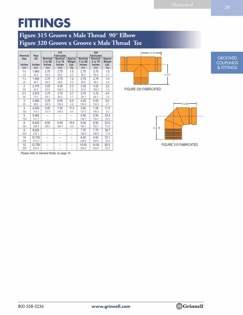
315 320Nominal Pipe Fabricated Fabricated
Size OD Nominal Nominal Approx Nominal Nominal ApproxC to GE C to TE Weight C to GE C to TE Weight
Inches Inches Inches Inches Lbs. Inches Inches Lbs.mm mm mm mm Kg mm mm Kg
11/4 1.660 2.75 2.75 1.0 2.75 2.75 1.532 42.4 69.9 69.9 0.5 69.9 69.9 0.7
11/2 1.900 2.75 2.75 1.2 2.75 2.75 1.940 48.3 69.9 69.9 0.5 69.9 69.9 0.9
2 2.375 3.25 4.25 2.3 3.25 4.25 3.250 60.3 82.6 108.0 1.0 82.6 108.0 1.5
21/2 2.875 3.75 3.75 3.7 3.75 3.75 4.065 73.0 95.3 95.3 1.7 95.3 95.3 1.8
3 3.500 4.25 6.00 6.5 4.25 6.00 6.080 88.9 108.0 152.4 2.9 108.0 152.4 2.7
4 4.500 5.00 7.25 11.0 5.00 7.25 11.0100 114.3 127.0 184.2 5.0 127.0 184.2 5.0
5 5.563 – – – 5.50 5.50 23.0125 141.3 – – – 139.7 139.7 10.5
6 6.625 6.50 6.50 19.8 6.50 6.50 23.0150 168.3 165.1 165.1 9.0 165.1 165.1 10.5
8 8.625 – – – 7.75 7.75 38.7200 219.1 – – – 196.9 196.9 17.6
10 10.750 – – – 9.00 9.00 72.1250 273.0 – – – 228.6 228.6 32.8
12 12.750 – – – 10.00 10.00 92.5300 323.9 – – – 254.0 254.0 42.0
Please refer to General Notes on page 14.
Figure 315 Groove x Male Thread 90° ElbowFigure 320 Groove x Groove x Male Thread Tee
FIGURE 315 FABRICATED
FIGURE 320 FABRICATED

FITTINGS
www.grinnell.com 800-558-5236
GROOVEDCOUPLINGS& FITTINGS
Mechanical30
260 360Nominal Pipe Cast Fabricated
Size OD Nominal Approx Nominal ApproxE to E Weight E to E Weight
Inches Inches Inches Lbs. Inches Lbs.mm mm mm Kg mm Kg
11/4 1.660 0.88 0.4 – –32 42.4 22.4 0.2 – –
11/2 1.900 0.88 0.6 – –40 48.3 22.4 0.3 – –
2 2.375 0.88 0.9 – –50 60.3 22.4 0.4 – –
21/2 2.875 0.88 0.9 – –65 73.0 22.4 0.4 – –
3.000 0.94 1.1 – –76.1 23.9 0.5 – –
3 3.500 0.88 1.1 – –80 88.9 22.4 0.5 – –
4 4.500 1.00 2.6 – –100 114.3 25.4 1.2 – –
5.500 0.92 4.7 – –139.7 23.4 2.1 – –
5 5.563 1.00 5.0 – –125 141.3 25.4 2.3 – –
6.500 1.00 7.5 – –165.1 25.4 3.4 – –
6 6.625 1.00 7.5 – –
150 168.3 25.4 3.4 – –
8 8.625 1.19 12.8 – –200 219.1 30.2 5.8 – –
10 10.750 1.25 20.0 – –250 273.0 31.8 9.1 – –
12 12.750 1.25 36.0 – –300 323.9 31.8 16.3 – –
14 14.000 – – 8.50 45.0350 355.6 – – 215.9 20.4
16 16.000 – – 9.00 50.3400 406.4 – – 228.6 22.8
18 18.000 – – 10.00 66.0450 457.2 – – 254.0 29.9
20 20.000 – – 11.00 88.00500 508.0 – – 279.4 39.9
24 24.000 – – 12.50 11.90600 609.6 – – 317.5 54.0
Figure 260 & 360 End Cap
* Sizes 11/4" through 12" are available with 1/2", 3/4" and
1" tap plug. Contact Tyco Fire & Building Products.
Please refer to General Notes on page 14.
FIGURE 260
CAST
11/4" - 12"
FIGURE 360
FABRICATED
14" - 24"
FITTINGS
www.grinnell.com800-558-5236
GROOVEDCOUPLINGS& FITTINGS
Mechanical31
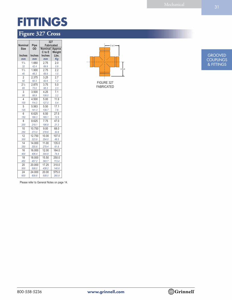
Figure 327 Cross
FIGURE 327
FABRICATED
327Nominal Pipe Fabricated
Size OD Nominal ApproxC to E Weight
Inches Inches Inches Lbs.mm mm mm Kg
11/4 1.660 2.75 2.032 42.4 69.9 0.9
11/2 1.900 2.75 2.240 48.3 69.9 1.0
2 2.375 3.25 2.750 60.3 82.6 1.2
21/2 2.875 3.75 5.065 73.0 95.3 2.3
3 3.500 4.25 7.180 88.9 108.0 3.2
4 4.500 5.00 11.9100 114.3 127.0 5.4
5 5.563 5.50 17.1125 141.3 139.7 7.8
6 6.625 6.50 27.5150 168.3 165.1 12.5
8 8.625 7.75 47.0
200 219.1 196.9 21.3
10 10.750 9.00 68.0250 273.0 278.6 30.8
12 12.750 10.00 107.0300 323.9 254.0 48.5
14 14.000 11.00 135.0350 355.6 279.4 61.8
16 16.000 12.00 164.0400 406.4 304.8 74.4
18 18.000 15.50 250.0450 457.2 393.7 113.4
20 20.000 17.25 310.0500 508.0 438.2 140.6
24 24.000 20.00 575.0600 609.6 508.0 260.8
Please refer to General Notes on page 14.

FITTINGS
www.grinnell.com 800-558-5236
GROOVEDCOUPLINGS& FITTINGS
Mechanical32
FIGURE 221 CAST
FIGURE 321 FABRICATED
Please refer to General Notes on page 14.
221 321Nominal Pipe Cast Fabricated
Size OD Nominal Approx Nominal ApproxC to E Weight C to E Weight
Inches Inches Inches Lbs. Inches Lbs.mm mm mm Kg mm Kg
11/2 x 11/2 x 11/4 1.900 x 1.900 x 1.660 – – 2.75 1.540 x 40 x 32 48.3 x 48.3 x 42.4 – – 69.9 0.7
2 x 2 x 11/2 2.375 x 2.375 x 1.900 3.25 2.7 3.25 2.750 x 50 x 40 60.3 x 60.6 x 48.3 82.6 1.2 82.6 1.2
21/2 x 21/2 x11/4 2.875 x 2.875 x 1.660 – – 3.75 4.265 x 65 x 32 73.0 x 73.0 x 42.4 – – 95.3 1.9
21/2 x 21/2 x 11/2 2.875 x 2.875 x 1.900 – – 3.75 4.265 x 65 x 40 73.0 x 73.0 x 48.3 – – 95.3 1.9
21/2 x 21/2 x 2 2.875 x 2.875 x 2.375 – – 3.75 4.365 x 65 x 50 73.0 x 73.0 x 60.3 – – 95.3 2.0
3 x 3 x 1 3.500 x 3.500 x 1.315 4.25 7.0 – –80 x 80 x 25 88.9 x 88.9 x 33.7 108.0 3.2 – –
3 x 3 x 11/2 3.500 x 3.500 x 1.900 – – 4.25 5.380 x 80 x 40 88.9 x 88.9 x 48.3 – – 108.0 2.4
3 x 3 x 2 3.500 x 3.500 x 2.375 4.25 5.5 4.25 5.580 x 80 x 50 88.9 x 88.9 x 60.3 108.0 2.5 108.0 2.5
3 x 3 x 21/2 3.500 x 3.500 x 2.875 – – 4.25 5.880 x 80 x 65 88.9 x 88.9 x 73.0 – – 108.0 2.6
4 x 4 x 11/4 4.500 x 4.500 x 1.660 – – 5.00 9.8100 x 100 x 32 114.3 x 114.3 x 42.4 – – 127.0 4.4
4 x 4 x 11/2 4.500 x 4.500 x 1.900 – – 5.00 9.9100 x 100 x 40 114.3 x 114.3 x 48.3 – – 127.0 4.5
4 x 4 x 2 4.500 x 4.500 x 2.375 5.00 10.2 5.00 10.1100 x 100 x 50 114.3 x 114.3 x 60.3 127.0 4.6 127.0 4.6
4 x 4 x 21/2 4.500 x 4.500 x 2.875 – – 5.00 10.3100 x 100 x 65 114.3 x 114.3 x 73.0 – – 127.0 4.7
4 x 4 x 3 4.500 x 4.500 x 3.500 5.00 11.4 5.00 10.5100 x 100 x 80 114.3 x 114.3 x 88.9 127.0 5.2 127.0 4.8
5 x 5 x 2 5.563 x 5.563 x 2.375 – – 5.50 14.5125 x 125 x 50 141.3 x 141.3 x 60.3 – – 139.7 6.6
5 x 5 x 21/2 5.563 x 5.563 x 2.875 – – 5.50 14.8125 x 125 x 65 141.3 x 141.3 x 73.0 – – 139.7 6.7
5 x 5 x 3 5.563 x 5.563 x 3.500 – – 5.50 15.2125 x 125 x 80 141.3 x 141.3 x 88.9 – – 139.7 6.9
5 x 5 x 4 5.563 x 5.563 x 4.500 – – 5.50 15.8125 x 125 x 100 141.3 x 141.3 x 114.3 – – 139.7 7.2
6 x 6 x 2 6.625 x 6.625 x 2.375 6.5 26.4 6.50 26.3150 x 150 x 50 168.3 x 168.3 x 60.3 165.1 12.0 165.1 11.9
6 x 6 x 21/2 6.625 x 6.625 x 2.875 – – 6.50 26.5150 x 150 x 65 168.3 x 168.3 x 73.0 – – 165.1 12.0
6 x 6 x 3 6.625 x 6.625 x 3.500 6.5 26.5 6.50 65.5150 x 150 x 80 168.3 x 168.3 x 88.9 165.1 12.0 165.1 12.0
6 x 6 x 4 6.625 x 6.625 x 4.500 6.5 26.5 6.50 26.6150 x 150 x 100 168.3 x 168.3 x 114.3 165.1 12.0 165.1 12.1
6 x 6 x 5 6.625 x 6.625 x 5.563 – – 6.50 27.0150 x 150 x 125 168.3 x 168.3 x 141.3 – – 165.1 12.2
8 x 8 x 2 8.625 x 8.625 x 2.375 – – 7.75 36.2200 x 200 x 50 219.1 x 219.1 x 60.3 – – 196.9 16.4
8 x 8 x 3 8.625 x 8.625 x 3.500 – – 7.75 36.5200 x 200 x 80 219.1 x 219.1 x 88.9 – – 196.9 16.6
8 x 8 x 4 8.625 x 8.625 x 4.500 – – 7.75 36.6200 x 200 x 100 219.1 x 219.1 x 114.3 – – 196.9 16.6
8 x 8 x 5 8.625 x 8.625 x 5.563 – – 7.75 36.8200 x 200 x 125 219.1 x 219.1 x 141.3 – – 196.9 16.7
8 x 8 x 6 8.625 x 8.625 x 6.625 – – 7.75 37.0200 x 200 x 150 219.1 x 219.1 x 168.3 – – 196.9 16.8
10 x 10 x 2 10.750 x 10.750 x 2.375 – – 9.00 57.1250 x 250 x 50 273.0 x 273.0 x 60.3 – – 228.6 25.9
Figure 221 & 321 Reducing Tee
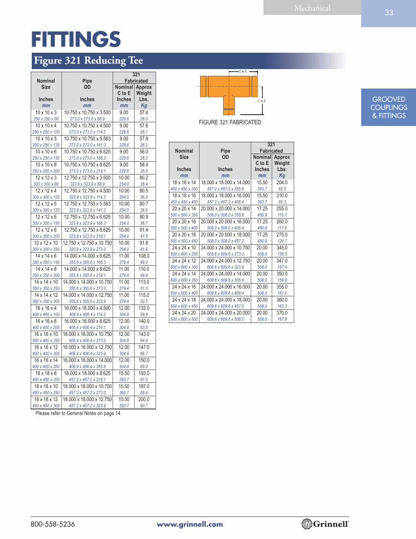
FITTINGS
www.grinnell.com800-558-5236
GROOVEDCOUPLINGS& FITTINGS
Mechanical33
321Nominal Pipe Fabricated
Size OD Nominal ApproxC to E Weight
Inches Inches Inches Lbs.mm mm mm Kg
10 x 10 x 3 10.750 x 10.750 x 3.500 9.00 57.4250 x 250 x 80 273.0 x 273.0 x 88.9 228.6 26.0
10 x 10 x 4 10.750 x 10.750 x 4.500 9.00 57.6250 x 250 x 100 273.0 x 273.0 x 114.3 228.6 26.1
10 x 10 x 5 10.750 x 10.750 x 5.563 9.00 57.8250 x 250 x 125 273.0 x 273.0 x 141.3 228.6 26.2
10 x 10 x 6 10.750 x 10.750 x 6.625 9.00 58.0250 x 250 x 150 273.0 x 273.0 x 168.3 228.6 26.3
10 x 10 x 8 10.750 x 10.750 x 8.625 9.00 58.4250 x 250 x 200 273.0 x 273.0 x 219.1 228.6 26.5
12 x 12 x 3 12.750 x 12.750 x 3.500 10.00 80.2300 x 300 x 80 323.9 x 323.9 x 88.9 254.0 36.4
12 x 12 x 4 12.750 x 12.750 x 4.500 10.00 80.5300 x 300 x 100 323.9 x 323.9 x 114.3 254.0 36.5
12 x 12 x 5 12.750 x 12.750 x 5.563 10.00 80.7300 x 300 x 125 323.9 x 323.9 x 141.3 254.0 36.6
12 x 12 x 6 12.750 x 12.750 x 6.625 10.00 80.9300 x 300 x 150 323.9 x 323.9 x 168.3 254.0 36.7
12 x 12 x 8 12.750 x 12.750 x 8.625 10.00 91.4300 x 300 x 200 323.9 x 323.9 x 219.1 254.0 41.5
12 x 12 x 10 12.750 x 12.750 x 10.750 10.00 91.8300 x 300 x 250 323.9 x 323.9 x 273.0 254.0 41.6
14 x 14 x 6 14.000 x 14.000 x 6.625 11.00 108.0350 x 350 x 150 355.6 x 355.6 x 168.3 279.4 49.0
14 x 14 x 8 14.000 x 14.000 x 8.625 11.00 110.0350 x 350 x 200 355.6 x 355.6 x 219.1 279.4 49.9
14 x 14 x 10 14.000 x 14.000 x 10.750 11.00 113.0350 x 350 x 250 355.6 x 355.6 x 273.0 279.4 51.3
14 x 14 x 12 14.000 x 14.000 x 12.750 11.00 115.0350 x 350 x 300 355.6 x 355.6 x 323.9 279.4 52.2
16 x 16 x 4 16.000 x 16.000 x 4.500 12.00 132.0400 x 400 x 100 406.4 x 406.4 x 114.3 304.8 59.9
16 x 16 x 8 16.000 x 16.000 x 8.625 12.00 140.0400 x 400 x 200 406.4 x 406.4 x 219.1 304.8 63.5
16 x 16 x 10 16.000 x 16.000 x 10.750 12.00 143.0400 x 400 x 250 406.4 x 406.4 x 273.0 304.8 64.9
16 x 16 x 12 16.000 x 16.000 x 12.750 12.00 147.0400 x 400 x 300 406.4 x 406.4 x 323.9 304.8 66.7
16 x 16 x 14 16.000 x 16.000 x 14.000 12.00 150.0400 x 400 x 350 406.4 x 406.4 x 355.6 304.8 68.0
18 x 18 x 8 18.000 x 18.000 x 8.625 15.50 193.0450 x 450 x 200 457.2 x 457.2 x 219.1 393.7 87.5
18 x 18 x 10 18.000 x 18.000 x 10.750 15.50 197.0450 x 450 x 250 457.2 x 457.2 x 273.0 393.7 89.4
18 x 18 x 12 18.000 x 18.000 x 12.750 15.50 200.0450 x 450 x 300 457.2 x 457.2 x 323.9 393.7 90.7
Please refer to General Notes on page 14.
Figure 321 Reducing Tee
FIGURE 321 FABRICATED
321Nominal Pipe Fabricated
Size OD Nominal ApproxC to E Weight
Inches Inches Inches Lbs.mm mm mm Kg
18 x 18 x 14 18.000 x 18.000 x 14.000 15.50 204.0450 x 450 x 350 457.2 x 457.2 x 355.6 393.7 92.5
18 x 18 x 16 18.000 x 18.000 x 16.000 15.50 210.0450 x 450 x 400 457.2 x 457.2 x 406.4 393.7 95.3
20 x 20 x 14 20.000 x 20.000 x 14.000 17.25 255.0500 x 500 x 350 508.0 x 508.0 x 355.6 450.9 115.7
20 x 20 x 16 20.000 x 20.000 x 16.000 17.25 260.0500 x 500 x 400 508.0 x 508.0 x 406.4 450.9 117.9
20 x 20 x 18 20.000 x 20.000 x 18.000 17.25 275.0500 x 500 x 450 508.0 x 508.0 x 457.2 450.9 124.7
24 x 24 x 10 24.000 x 24.000 x 10.750 20.00 345.0600 x 600 x 250 609.6 x 609.6 x 273.0 508.0 156.5
24 x 24 x 12 24.000 x 24.000 x 12.750 20.00 347.0600 x 600 x 300 609.6 x 609.6 x 323.9 508.0 157.4
24 x 24 x 14 24.000 x 24.000 x 14.000 20.00 350.0600 x 600 x 350 609.6 x 609.6 x 355.6 508.0 158.8
24 x 24 x 16 24.000 x 24.000 x 16.000 20.00 355.0600 x 600 x 400 609.6 x 609.6 x 406.4 508.0 161.0
24 x 24 x 18 24.000 x 24.000 x 18.000 20.00 360.0600 x 600 x 450 609.6 x 609.6 x 457.2 508.0 163.3
24 x 24 x 20 24.000 x 24.000 x 20.000 20.00 370.0600 x 600 x 500 609.6 x 609.6 x 508.0 508.0 167.8

FITTINGS
www.grinnell.com 800-558-5236
GROOVEDCOUPLINGS& FITTINGS
Mechanical34
FIGURE 323
FABRICATED
Please refer to General Notes on page 14.
323Nominal Pipe Fabricated
Size OD Nominal Nominal ApproxC to GE C to TE Weight
Inches Inches Inches Inches Lbs.mm mm mm mm Kg
11/2 x 11/2 x 11/4 1.900 x 1.900 x 1.660 3.25 3.25 2.740 x 40 x 32 48.3 x 48.3 x 42.4 82.6 82.6 1.2
2 x 2 x 11/2 2.375 x 2.375 x 1.900 3.25 3.25 2.750 x 50 x 40 60.3 x 60.6 x 48.3 82.6 82.6 1.2
21/2 x 21/2 x11/4 2.875 x 2.875 x 1.660 3.75 3.75 4.365 x 65 x 32 73.0 x 73.0 x 42.4 95.3 95.3 2.0
21/2 x 21/2 x 11/2 2.875 x 2.875 x 1.900 3.75 3.75 4.265 x 65 x 40 73.0 x 73.0 x 48.3 95.3 95.3 1.9
21/2 x 21/2 x 2 2.875 x 2.875 x 2.375 3.75 3.75 4.365 x 65 x 50 73.0 x 73.0 x 60.3 95.3 95.3 2.0
3 x 3 x 11/2 3.500 x 3.500 x 1.900 4.25 4.25 5.380 x 80 x 40 88.9 x 88.9 x 48.3 108.0 108.0 2.4
3 x 3 x 2 3.500 x 3.500 x 2.375 4.25 4.25 5.580 x 80 x 50 88.9 x 88.9 x 60.3 108.0 108.0 2.5
3 x 3 x 21/2 3.500 x 3.500 x 2.875 4.25 4.25 5.880 x 80 x 65 88.9 x 88.9 x 73.0 108.0 108.0 2.6
4 x 4 x 11/2 4.500 x 4.500 x 1.900 5.00 5.00 9.9100 x 100 x 40 114.3 x 114.3 x 48.3 127.0 127.0 4.5
4 x 4 x 2 4.500 x 4.500 x 2.375 5.00 5.00 10.1100 x 100 x 50 114.3 x 114.3 x 60.3 127.0 127.0 4.6
4 x 4 x 21/2 4.500 x 4.500 x 2.875 5.00 5.00 10.3100 x 100 x 65 114.3 x 114.3 x 73.0 127.0 127.0 4.7
4 x 4 x 3 4.500 x 4.500 x 3.500 5.00 5.00 10.5100 x 100 x 80 114.3 x 114.3 x 88.9 127.0 127.0 4.8
5 x 5 x 2 5.563 x 5.563 x 2.375 5.50 5.50 14.5125 x 125 x 50 141.3 x 141.3 x 60.3 139.7 139.7 6.6
5 x 5 x 3 5.563 x 5.563 x 3.500 5.50 5.50 15.2125 x 125 x 80 141.3 x 141.3 x 88.9 139.7 139.7 6.9
5 x 5 x 4 5.563 x 5.563 x 4.500 5.50 5.50 15.8125 x 125 x 100 141.3 x 141.3 x 114.3 139.7 139.7 7.2
6 x 6 x 2 6.625 x 6.625 x 2.375 6.50 6.50 26.3150 x 150 x 50 168.3 x 168.3 x 60.3 165.1 165.1 11.9
6 x 6 x 21/2 6.625 x 6.625 x 2.875 6.50 6.50 26.5150 x 150 x 65 168.3 x 168.3 x 73.0 165.1 165.1 12.0
6 x 6 x 3 6.625 x 6.625 x 3.500 6.50 6.50 26.5150 x 150 x 80 168.3 x 168.3 x 88.9 165.1 165.1 12.0
6 x 6 x 4 6.625 x 6.625 x 4.500 6.50 6.50 26.6150 x 150 x 100 168.3 x 168.3 x 114.3 165.1 165.1 12.1
6 x 6 x 5 6.625 x 6.625 x 5.563 6.50 6.50 27.0150 x 150 x 125 168.3 x 168.3 x 141.3 165.1 165.1 12.2
8 x 8 x 2 8.625 x 8.625 x 2.375 7.75 7.75 36.2200 x 200 x 50 219.1 x 219.1 x 60.3 196.9 196.9 16.4
8 x 8 x 3 8.625 x 8.625 x 3.500 7.75 7.75 36.5200 x 200 x 80 219.1 x 219.1 x 88.9 196.9 196.9 16.6
8 x 8 x 4 8.625 x 8.625 x 4.500 7.75 7.75 36.6200 x 200 x 100 219.1 x 219.1 x 114.1 196.9 196.9 16.6
8 x 8 x 5 8.625 x 8.625 x 5.563 7.75 7.75 36.8200 x 200 x 125 219.1 x 219.1 x 141.3 196.9 196.9 16.7
8 x 8 x 6 8.625 x 8.625 x 6.625 7.75 7.75 37.0200 x 200 x 150 219.1 x 219.1 x 168.3 196.9 196.9 16.8
Figure 323 Groove x Groove x Male Thread Reducing Tee

FITTINGS
www.grinnell.com800-558-5236
GROOVEDCOUPLINGS& FITTINGS
Mechanical35
Please refer to General Notes on page 14.
323Nominal Pipe Fabricated
Size OD Nominal Nominal ApproxC to GE C to TE Weight
Inches Inches Inches Inches Lbs.mm mm mm mm Kg
10 x 10 x 2 10.750 x 10.750 x 2.375 9.00 9.00 57.1250 x 250 x 50 273.0 x 273.0 x 60.3 228.6 228.6 25.9
10 x 10 x 3 10.750 x 10.750 x 3.500 9.00 9.00 57.4250 x 250 x 80 273.0 x 273.0 x 88.9 228.6 228.6 26.0
10 x 10 x 4 10.750 x 10.750 x 4.500 9.00 9.00 57.6250 x 250 x 100 273.0 x 273.0 x 114.3 228.6 228.6 26.1
10 x 10 x 5 10.750 x 10.750 x 5.563 9.00 9.00 57.8250 x 250 x 125 273.0 x 273.0 x 141.3 228.6 228.6 26.2
10 x 10 x 6 10.750 x 10.750 x 6.625 9.00 9.00 58.0250 x 250 x 150 273.0 x 273.0 x 168.3 228.6 228.6 26.3
10 x 10 x 8 10.750 x 10.750 x 8.625 9.00 9.00 58.4250 x 250 x 200 273.0 x 273.0 x 219.1 228.6 228.6 26.5
12 x 12 x 3 12.750 x 12.750 x 3.500 10.00 10.00 80.2300 x 300 x 80 323.9 x 323.9 x 88.9 254.0 254.0 36.4
12 x 12 x 4 12.750 x 12.750 x 4.500 10.00 10.00 80.5300 x 300 x 100 323.9 x 323.9 x 114.3 254.0 254.0 36.5
12 x 12 x 5 12.750 x 12.750 x 5.563 10.00 10.00 80.7300 x 300 x 125 323.9 x 323.9 x 141.3 254.0 254.0 36.6
12 x 12 x 6 12.750 x 12.750 x 6.625 10.00 10.00 80.9300 x 300 x 150 323.9 x 323.9 x 168.3 254.0 254.0 36.7
12 x 12 x 8 12.750 x 12.750 x 8.625 10.00 10.00 91.4300 x 300 x 200 323.9 x 323.9 x 219.1 254.0 254.0 41.5
12 x 12 x 10 12.750 x 12.750 x 10.750 10.00 10.00 91.8300 x 300 x 250 323.9 x 323.9 x 273.0 254.0 254.0 41.6
14 x 14 x 6 14.000 x 14.000 x 6.625 11.00 11.00 109.6350 x 350 x 150 355.6 x 355.6 x 168.3 279.4 279.4 49.7
14 x 14 x 8 14.000 x 14.000 x 8.625 11.00 11.00 110.0350 x 350 x 200 355.6 x 355.6 x 219.1 279.4 279.4 49.9
14 x 14 x 10 14.000 x 14.000 x 10.750 11.00 11.00 113.0350 x 350 x 250 355.6 x 355.6 x 273.0 279.4 279.4 51.3
14 x 14 x 12 14.000 x 14.000 x 12.750 11.00 11.00 115.0350 x 350 x 300 355.6 x 355.6 x 323.9 279.4 279.4 52.2
16 x 16 x 8 16.000 x 16.000 x 8.625 12.00 12.00 140.0400 x 400 x 200 406.4 x 406.4 x 219.1 304.8 304.8 63.5
16 x 16 x 10 16.000 x 16.000 x 10.750 12.00 12.00 143.0400 x 400 x 250 406.4 x 406.4 x 273.0 304.8 304.8 64.9
16 x 16 x 12 16.000 x 16.000 x 12.750 12.00 12.00 147.0400 x 400 x 300 406.4 x 406.4 x 323.9 304.8 304.8 66.7
18 x 18 x 8 18.000 x 18.000 x 8.625 15.50 15.50 193.0450 x 450 x 200 457.2 x 457.2 x 219.1 393.7 393.7 87.5
18 x 18 x 10 18.000 x 18.000 x 10.750 15.50 15.50 197.0450 x 450 x 250 457.2 x 457.2 x 273.0 393.7 393.7 98.4
18 x 18 x 12 18.000 x 18.000 x 12.750 15.50 15.50 200.0450 x 450 x 300 457.2 x 457.2 x 323.9 393.7 393.7 90.7
18 x 18 x 14 18.000 x 18.000 x 14.000 15.50 15.50 211.0450 x 450 x 350 457.2 x 457.2 x 355.6 393.7 393.7 95.7
18 x 18 x 16 18.000 x 18.000 x 16.000 15.50 15.50 216.0450 x 450 x 400 457.2 x 457.2 x 406.4 393.7 393.7 98.0
24 x 24 x 8 24.000 x 24.000 x 8.625 20.00 20.00 334.0600 x 600 x 200 609.6 x 609.6 x 219.1 508.0 508.0 151.5
24 x 24 x 10 24.000 x 24.000 x 10.750 20.00 20.00 345.0600 x 600 x 250 609.6 x 609.6 x 273.0 508.0 508.0 156.5
24 x 24 x 12 24.000 x 24.000 x 12.750 20.00 20.00 347.0600 x 600 x 300 609.6 x 609.6 x 323.9 508.0 508.0 157.4
FIGURE 323
FABRICATED
Figure 323 Groove x Groove x Male Thread Reducing Tee
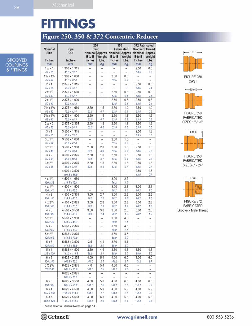
FITTINGS
www.grinnell.com 800-558-5236
GROOVEDCOUPLINGS& FITTINGS
Mechanical36
Please refer to General Notes on page 14.
250 350 372 FabricatedNominal Pipe Cast Fabricated Groove x Thread
Size OD Nominal Approx Nominal Approx Nominal ApproxE to E Weight E to E Weight E to E Weight
Inches Inches Inches Lbs. Inches Lbs. Inches Lbs.mm mm mm Kg mm Kg mm Kg
11/2 x 1 1.900 x 1.315 – – – – 2.50 0.640 x 25 48.3 x 33.7 – – – – 63.5 0.3
11/2 x 11/4 1.900 x 1.660 – – 2.50 0.6 – –40 x 32 48.3 x 42.4 – – 63.5 0.3 – –
2 x 1 2.375 x 1.315 – – – – 2.50 0.850 x 25 60.3 x 33.7 – – – – 63.5 0.4
2 x 11/4 2.375 x 1.660 – – 2.50 0.8 2.50 0.850 x 32 60.3 x 42.4 – – 63.5 0.4 63.5 0.4
2 x 11/2 2.375 x 1.900 – – 2.50 0.8 2.50 0.850 x 40 60.3 x 48.3 – – 63.5 0.4 63.5 0.4
21/2 x 11/4 2.875 x 1.660 2.50 1.5 2.50 1.0 2.50 1.065 x 32 73.0 x 42.4 63.5 0.7 63.5 0.5 63.5 0.5
21/2 x 11/2 2.875 x 1.900 2.50 1.5 2.50 1.3 2.50 1.365 x 40 73.0 x 48.3 63.5 0.7 63.5 0.6 63.5 0.6
21/2 x 2 2.875 x 2.375 2.50 1.2 2.50 1.2 2.50 1.265 x 50 73.0 x 60.3 63.5 0.5 63.5 0.5 63.5 0.5
3 x 1 3.500 x 1.315 – – – – 2.50 1.380 x 25 88.9 x 33.7 – – – – 63.5 0.6
3 x 11/4 3.500 x 1.660 – – 2.50 1.3 – –80 x 32 88.9 x 42.4 – – 63.5 0.6 – –
3 x 11/2 3.500 x 1.900 2.50 2.0 2.50 1.3 2.50 1.380 x 40 88.9 x 48.3 63.5 0.9 63.5 0.6 63.5 0.6
3 x 2 3.500 x 2.375 2.50 1.6 2.50 1.3 2.50 1.380 x 50 88.9 x 60.3 63.5 0.7 63.5 0.6 63.5 0.6
3 x 21/2 3.500 x 2.875 2.50 1.8 2.50 1.5 2.50 1.580 x 65 88.9 x 73.0 63.5 0.8 63.5 0.7 63.5 0.7
4.000 x 3.500 – – – – 2.50 1.5101.6 x 88.9 – – – – 63.5 0.7
4 x 11/4 4.500 x 1.660 – – 3.00 2.2 – –100 x 32 114.3 x 42.4 – – 76.2 1.0 – –
4 x 11/2 4.500 x 1.900 – – 3.00 2.3 3.00 2.3100 x 40 114.3 x 48.3 – – 76.2 1.0 76.2 1.0
4 x 2 4.500 x 2.375 3.00 2.7 3.00 2.3 3.00 2.3100 x 50 114.3 x 60.3 76.2 1.2 76.2 1.0 76.2 1.0
4 x 21/2 4.500 x 2.875 3.00 2.8 3.00 2.3 3.00 2.3100 x 65 114.3 x 73.0 76.2 1.3 76.2 1.0 76.2 1.0
4 x 3 4.500 x 3.500 3.00 3.0 3.00 2.6 3.00 2.6100 x 80 114.3 x 88.9 76.2 1.4 76.2 1.2 76.2 1.2
5 x 11/2 5.563 x 1.900 – – 3.50 4.6 – –125 x 40 141.3 x 48.3 – – 88.9 2.1 – –
5 x 2 5.563 x 2.375 – – 3.50 4.6 – –125 x 50 141.3 x 60.3 – – 88.9 2.1 – –
5 x 21/2 5.563 x 2.875 – – 3.50 4.5 – –125 x 65 141.3 x 73.0 – – 88.9 2.0 – –
5 x 3 5.563 x 3.500 3.5 4.4 3.50 4.4 – –125 x 80 141.3 x 88.9 88.9 2.0 88.9 2.0 – –
5 x 4 5.563 x 4.500 3.50 4.6 3.50 4.5 3.50 4.5125 x 100 141.3 x 114.3 88.9 2.1 88.9 2.0 88.9 2.0
6 x 2 6.625 x 2.375 4.00 5.4 4.00 6.0 4.00 6.0150 x 50 168.3 x 60.3 101.6 2.5 101.6 2.7 101.6 2.7
6 X 21/2 6.625 x 2.875 4.0 5.4 4.00 6.0 – –150 X 65 168.3 x 73.0 101.6 2.5 101.6 2.7 – –
6.625 x 2.875 – – – – – –168.3 x 76.1 – – – – – –
6 x 3 6.625 x 3.500 4.00 5.8 4.00 6.0 4.00 6.0150 x 80 168.3 x 88.9 101.6 2.6 101.6 2.7 101.6 2.7
6 x 4 6.625 x 4.500 4.00 5.9 4.00 5.9 4.00 5.9150 x 100 168.3 x 114.3 101.6 2.7 101.6 2.7 101.6 2.7
6 X 5 6.625 x 5.563 4.00 6.3 4.00 5.8 4.00 5.8150 X 125 168.3 x 141.3 101.6 2.9 101.6 2.6 101.6 2.6
Figure 250, 350 & 372 Concentric Reducer
FIGURE 250
CAST
FIGURE 350
FABRICATED
SIZES 11/2" - 6"
FIGURE 350
FABRICATED
SIZES 8" - 24"
FIGURE 372
FABRICATED
Groove x Male Thread

FITTINGS
www.grinnell.com800-558-5236
GROOVEDCOUPLINGS& FITTINGS
Mechanical37
FIGURE 250
CAST
FIGURE 350
FABRICATED
SIZES 11/2" - 6"
250 350 372 FabricatedNominal Pipe Cast Fabricated Groove x Thread
Size OD Nominal Approx Nominal Approx Nominal ApproxE to E Weight E to E Weight E to E Weight
Inches Inches Inches Lbs. Inches Lbs. Inches Lbs.mm mm mm Kg mm Kg mm Kg
8 x 2 8.625 x 2.375 – – 5.00 12.2 – –200 x 50 219.1 x 60.3 – – 127.0 5.5 – –
8 x 21/2 8.625 x 2.875 – – 5.00 12.1 – –200 x 65 219.1 x 73.0 – – 127.0 5.5 – –
8 x 3 8.625 x 3.500 5.0 11.7 5.00 12.0 – –200 x 80 219.1 x 88.9 127.0 5.3 127.0 5.5 – –
8 x 4 8.625 x 4.500 5.0 11.1 5.00 11.9 – –200 x 100 219.1 x 114.3 127.0 5.0 127.0 5.4 – –
8 x 5 8.625 x 5.563 5.0 11.7 5.00 11.3 – –200 x 125 219.1 x 141.3 127.0 5.3 127.0 5.1 – –
8 x 6 8.625 x 6.625 5.0 11.8 5.00 10.8 – –200 x 150 219.1 x 168.3 127.0 5.4 127.0 4.9 – –
10 x 4 10.750 x 4.500 – – 6.00 21.9 – –250 x 100 273.0 x 114.3 – – 152.4 10.0 – –
10 x 5 10.750 x 5.563 – – 6.00 21.6 – –250 x 125 273.0 x 141.3 – – 152.4 9.8 – –
10 x 6 10.750 x 6.625 – – 6.00 21.1 – –250 x 150 273.0 x 168.3 – – 152.4 9.6 – –
10 x 8 10.750 x 8.625 – – 6.00 19.5 – –250 x 200 273.0 x 219.1 – – 152.4 8.9 – –
12 x 4 12.750 x 4.500 – – 7.00 28.0 – –300 x 100 323.9 x 114.3 – – 177.8 12.7 – –
12 x 6 12.750 x 6.625 – – 7.00 30.0 – –300 x 150 323.9 x 168.3 – – 177.8 13.6 – –
12 x 8 12.750 x 8.625 – – 7.00 28.0 – –300 x 200 323.9 x 219.1 – – 177.8 12.7 – –
12 x 10 12.750 x 10.750 – – 7.00 33.0 – –300 x 250 323.9 x 273.0 – – 177.8 15.0 – –
14 x 6 14.000 x 6.625 – – 13.00 58.0 – –350 x 150 355.6 x 168.3 – – 330.2 26.4 – –
14 x 8 14.000 x 8.625 – – 13.00 58.5 – –350 x 200 355.6 x 219.1 – – 330.2 26.6 – –
14 x 10 14.000 x 10.750 – – 13.00 59.3 – –350 x 250 355.6 x 273.0 – – 330.2 27.0 – –
14 x 12 14.000 x 12.750 – – 13.00 60.0 – –350 x 300 355.6 x 323.9 – – 330.2 27.3 – –
16 x 8 16.000 x 8.625 – – 14.00 68.5 – –400 x 200 406.4 x 219.1 – – 355.6 31.1 – –
16 x 10 16.000 x 10.750 – – 14.00 69.5 – –400 x 250 406.4 x 273.0 – – 355.6 31.6 – –
16 x 12 16.000 x 12.750 – – 14.00 70.0 – –400 x 300 406.4 x 323.9 – – 355.6 31.8 – –
16 x 14 16.000 x 14.000 – – 14.00 71.0 – –400 x 350 406.4 x 355.6 – – 355.6 32.3 – –
18 x 12 18.000 x 12.750 – – 15.00 83.0 – –450 x 300 457.2 x 323.9 – – 381.0 37.7 – –
18 x 14 18.000 x 14.000 – – 15.00 84.0 – –450 x 350 457.2 x 355.6 – – 381.0 38.2 – –
18 x 16 18.000 x 16.000 – – 15.00 85.0 – –450 x 400 457.2 x 406.4 – – 381.0 38.6 – –
20 x 10 20.000 x 10.750 – – 20.00 115.0 – –500 x 250 508.0 x 273.0 – – 508.0 52.3 – –
20 x 12 20.000 x 12.750 – – 20.00 120.0 – –500 x 300 508.0 x 323.9 – – 508.0 54.5 – –
20 x 14 20.000 x 14.000 – – 20.00 122.0 – –500 x 350 508.0 x 355.6 – – 508.0 55.5 – –
20 x 16 20.000 x 16.000 – – 20.00 124.0 – –500 x 400 508.0 x 406.4 – – 508.0 56.4 – –
20 x 18 20.000 x 18.000 – – 20.00 125.0 – –500 x 450 508.0 x 457.2 – – 508.0 56.8 – –
24 x 10 24.000 x 10.750 – – 20.00 147.0 – –600 x 250 609.6 x 273.0 – – 508.0 66.8 – –
FIGURE 350
FABRICATED
SIZES 8" - 24"
FIGURE 372
FABRICATED
Groove x Male Thread
Figure 250, 350 & 372 Concentric Reducer
250 350 372 FabricatedNominal Pipe Cast Fabricated Groove xThread
Size OD Nominal Approx Nominal Approx Nominal ApproxE to E Weight E to E Weight E to E Weight
Inches Inches Inches Lbs. Inches Lbs. Inches Lbs.mm mm mm Kg mm Kg mm Kg
24 x 12 24.000 x 12.750 – – 20.00 138.0 – –600 x 300 609.6 x 323.9 – – 508.0 62.7 – –
24 x 14 24.000 x 14.000 – – 20.00 140.0 – –600 x 350 609.6 x 355.6 – – 508.0 63.6 – –
24 x 16 24.000 x 16.000 – – 20.00 145.0 – –600 x 400 609.6 x 406.4 – – 508.0 65.9 – –
24 x 18 24.000 x 18.000 – – 20.00 148.0 – –600 x 450 609.6 x 457.2 – – 508.0 67.3 – –
24 x 20 24.000 x 20.000 – – 20.00 150.0 – –600 x 500 609.6 x 508.0 – – 508.0 68.2 – –
Please refer to General Notes on page 14.

FITTINGS
www.grinnell.com 800-558-5236
GROOVEDCOUPLINGS& FITTINGS
Mechanical38
Please refer to General Notes on page 14.
251 351Nominal Pipe Cast Fabricated
Size OD Nominal Approx Nominal ApproxE to E Weight E to E Weight
Inches Inches Inches Lbs. Inches Lbs.mm mm mm Kg mm Kg
10 x 8 10.750 x 8.625 – – 13.00 34.4250 x 200 273.0 x 219.1 – – 330.2 15.6
12 x 4 12.750 x 4.500 – – 14.00 44.8300 x 100 323.9 x 114.3 – – 355.6 20.3
12 x 6 12.750 x 6.625 – – 14.00 45.2300 x 150 323.9 x 168.3 – – 355.6 20.5
12 x 8 12.750 x 8.625 – – 14.00 47.7300 x 200 323.9 x 219.1 – – 355.6 21.6
12 x 10 12.750 x 10.750 – – 14.00 52.0300 x 250 323.9 x 273.0 – – 355.6 23.6
14 x 6 14.000 x 6.625 – – 13.00 78.0350 x 150 355.6 x 168.3 – – 330.2 35.4
14 x 8 14.000 x 8.625 – – 13.00 80.0350 x 200 355.6 x 219.1 – – 330.2 36.3
14 x 10 14.000 x 10.750 – – 13.00 84.0350 x 250 355.6 x 273.0 – – 330.2 38.1
14 x 12 14.000 x 12.750 – – 13.00 88.0350 x 300 355.6 x 323.9 – – 330.2 39.9
16 x 8 16.000 x 8.625 – – 14.00 91.0400 x 200 406.4 x 219.1 – – 355.6 41.3
16 x 10 16.000 x 10.750 – – 14.00 96.0400 x 250 406.4 x 273.0 – – 355.6 43.5
16 x 12 16.000 x 12.750 – – 14.00 99.0400 x 300 406.4 x 323.9 – – 355.6 44.9
16 x 14 16.000 x 14.000 – – 14.00 104.0400 x 350 406.4 x 355.6 – – 355.6 47.2
18 x 10 18.000 x 10.750 – – 15.00 110.0450 x 250 457.2 x 273.0 – – 381.0 49.9
18 x 12 18.000 x 12.750 – – 15.00 113.0450 x 300 457.2 x 323.9 – – 381.0 51.3
18 x 14 18.000 x 14.000 – – 15.00 117.0450 x 350 457.2 x 355.6 – – 381.0 53.1
18 x 16 18.000 x 16.000 – – 15.00 121.0450 x 400 457.2 x 406.4 – – 381.0 54.9
20 x 10 20.000 x 10.750 – – 20.00 145.0500 x 250 508.0 x 273.0 – – 508.0 65.8
20 x 12 20.000 x 12.750 – – 20.00 149.0500 x 300 508.0 x 323.9 – – 508.0 67.6
20 x 14 20.000 x 14.000 – – 20.00 152.0500 x 350 508.0 x 355.6 – – 508.0 68.9
20 x 16 20.000 x 16.000 – – 20.00 156.0500 x 400 508.0 x 406.4 – – 508.0 70.8
20 x 18 20.000 x 18.000 – – 20.00 160.0500 x 450 508.0 x 457.2 – – 508.0 72.6
24 x 10 24.000 x 10.750 – – 20.00 147.0600 x 250 609.6 x 273.0 – – 508.0 78.9
24 x 12 24.000 x 12.750 – – 20.00 179.0600 x 300 609.6 x 323.9 – – 508.0 81.2
24 x 14 24.000 x 14.000 – – 20.00 184.0600 x 350 609.6 x 355.6 – – 508.0 83.5
24 x 16 24.000 x 16.000 – – 20.00 189.0600 x 400 609.6 x 406.4 – – 508.0 85.7
24 x 18 24.000 x 18.000 – – 20.00 194.0600 x 450 609.6 x 457.2 – – 508.0 88.0
24 x 20 24.000 x 20.000 – – 20.00 199.0600 x 500 609.6 x 508.0 – – 508.0 90.3
251 351Nominal Pipe Cast Fabricated
Size OD Nominal Approx Nominal ApproxE to E Weight E to E Weight
Inches Inches Inches Lbs. Inches Lbs.mm mm mm Kg mm Kg
11/2 x 11/4 1.900 x 1.660 – – 8.50 4.540 x 32 48.3 x 42.4 – – 215.9 2.0
2 x 11/4 2.375 x 1.660 – – 9.00 2.450 x 32 60.3 x 42.4 – – 228.6 1.1
2 x 11/2 2.375 x 1.900 – – 9.00 2.550 x 40 60.3 x 48.3 – – 228.6 1.1
21/2 x 11/4 2.875 x 1.660 – – 9.50 3.465 x 32 73.0 x 42.4 – – 241.3 1.5
21/2 x 11/2 2.875 x 1.900 – – 9.50 3.665 x 40 73.0 x 48.3 – – 241.3 1.6
21/2 x 2 2.875 x 2.375 – – 9.50 4.065 x 50 73.0 x 60.3 – – 241.3 1.8
3 x 11/4 3.500 x 1.660 – – 9.50 4.380 x 32 88.9 x 42.4 – – 241.3 2.0
3 x 11/2 3.500 x 1.900 – – 9.50 4.580 x 40 88.9 x 48.3 – – 241.3 2.0
3 x 2 3.500 x 2.375 3.50 1.8 9.50 4.880 x 50 88.9 x 60.3 88.9 .8 241.3 2.2
3 x 21/2 3.500 x 2.875 3.50 2.0 9.50 5.680 x 65 88.9 x 73.0 88.9 .9 241.3 2.5
4 x 11/4 4.500 x 1.660 – – 10.00 6.3100 x 32 114.3 x 42.4 – – 254.0 2.9
4 x 11/2 4.500 x 1.900 – – 10.00 6.4100 x 40 114.3 x 48.3 – – 254.0 2.9
4 x 2 4.500 x 2.375 4.0 2.8 10.00 6.7100 x 50 114.3 x 60.3 101.6 1.3 254.0 3.0
4 x 21/2 4.500 x 2.875 4.0 3.1 10.00 7.3100 x 65 114.3 x 73.0 101.6 1.4 254.0 3.3
4 x 3 4.500 x 3.500 4.0 3.3 10.00 7.9100 x 80 114.3 x 88.9 101.6 1.5 254.0 3.6
5 x 2 5.563 x 2.375 – – 11.00 9.3125 x 50 141.3 x 60.3 – – 279.4 4.2
5 x 21/2 5.563 x 2.875 – – 11.00 9.9125 x 65 141.3 x 73.0 – – 279.4 4.5
5 x 3 5.563 x 3.500 – – 11.00 10.7125 x 80 141.3 x 88.9 – – 279.4 4.9
5 x 4 5.563 x 4.500 5.0 5.7 11.00 11.9125 x 100 141.3 x 114.3 127.0 2.6 279.4 5.4
6 x 2 6.625 x 2.375 – – 11.50 12.2150 x 50 168.3 x 60.3 – – 292.1 5.5
6 x 21/2 6.625 x 2.875 – – 11.50 12.8150 x 65 168.3 x 73.0 – – 292.1 5.8
6 x 3 6.625 x 3.500 5.5 6.7 11.50 13.6150 x 80 168.3 x 88.9 139.7 3.0 292.1 6.2
6 x 4 6.625 x 4.500 5.5 7.2 11.50 14.9150 x 100 168.3 x 114.3 139.7 3.3 292.1 6.8
6 x 5 6.625 x 5.563 5.5 7.8 11.50 16.2150 x 125 168.3 x 141.3 139.7 3.5 292.1 7.3
8 x 3 8.625 x 3.500 – – 12.00 17.9200 x 80 219.1 x 88.9 – – 304.8 8.1
8 x 4 8.625 x 4.500 – – 12.00 19.7200 x 100 219.1 x 114.3 – – 304.8 8.9
8 x 5 8.625 x 5.563 – – 12.00 21.4200 x 125 219.1 x 141.3 – – 304.8 9.7
8 x 6 8.625 x 6.625 – – 12.00 23.2200 x 150 219.1 x 168.3 – – 304.8 10.5
10 x 4 10.750 x 4.500 – – 13.00 29.7250 x 100 273.0 x 114.3 – – 330.2 13.5
10 x 5 10.750 x 5.563 – – 13.00 31.7250 x 125 273.0 x 141.3 – – 330.2 14.4
10 x 6 10.750 x 6.625 – – 13.00 34.0250 x 150 273.0 x 168.3 – – 330.2 15.4
Figure 251 & 351 Eccentric Reducer
FIGURE 251 CAST
FIGURE 351 FABRICATED
Groove x Groove

FITTINGS
www.grinnell.com800-558-5236
GROOVEDCOUPLINGS& FITTINGS
Mechanical39
Please refer to General Notes on page 14.
397, 398 & 399Nominal Pipe Fabricated
Size OD Nominal ApproxE to E Weight
Inches Inches Inches Lbs.mm mm mm Kg
2 x 11/4 2.375 x 1.660 6.50 2.050 x 32 60.3 x 42.4 165.1 0.9
2 x 11/2 2.375 x 1.900 6.50 2.050 x 40 60.3 x 48.3 165.1 0.9
21/2 x 11/4 2.875 x 1.660 7.00 3.565 x 32 73.0 x 42.4 177.8 1.6
21/2 x 11/2 2.875 x 1.900 7.00 3.565 x 40 73.0 x 48.3 177.8 1.6
21/2 x 2 2.875 x 2.375 7.00 3.565 x 50 73.0 x 60.3 177.8 1.6
3 x 11/4 3.500 x 1.660 8.00 5.080 x 32 88.9 x 42.4 203.2 2.3
3 x 11/2 3.500 x 1.900 8.00 5.080 x 40 88.9 x 48.3 203.2 2.3
3 x 2 3.500 x 2.375 8.00 5.080 x 50 88.9 x 60.3 203.2 2.3
3 x 21/2 3.500 x 2.875 8.00 5.080 x 65 88.9 x 73.0 203.2 2.3
4 x 11/4 4.500 x 1.660 9.00 8.0100 x 32 114.3 x 42.4 228.6 3.6
4 x 11/2 4.500 x 1.900 9.00 8.0100 x 40 114.3 x 48.3 228.6 3.6
4 x 2 4.500 x 2.375 9.00 8.0100 x 50 114.3 x 60.3 228.6 3.6
4 x 21/2 4.500 x 2.875 9.00 8.0100 x 65 114.3 x 73.0 228.6 3.6
4 x 3 4.500 x 3.500 9.00 8.0100 x 80 114.3 x 88.9 228.6 3.6
5 x 11/2 5.563 x 1.900 11.00 12.0125 x 40 141.3 x 48.3 279.4 5.4
5 x 2 5.563 x 2.375 11.00 12.0125 x 50 141.3 x 60.3 279.4 5.4
5 x 21/2 5.563 x 2.875 11.00 12.0125 x 65 141.3 x 73.0 279.4 5.4
5 x 3 5.563 x 3.500 11.00 12.0125 x 80 141.3 x 88.9 279.4 5.4
5 x 4 5.563 x 4.500 11.00 12.0125 x 100 141.3 x 114.3 279.4 5.4
6 x 2 6.625 x 2.375 12.00 19.0150 x 50 168.3 x 60.3 304.8 8.6
6 x 21/2 6.625 x 2.875 12.00 19.0150 x 65 168.3 x 73.0 304.8 8.6
6 x 3 6.625 x 3.500 12.00 19.0150 x 80 168.3 x 88.9 304.8 8.6
6 x 4 6.625 x 4.500 12.00 19.0150 x 100 168.3 x 114.3 304.8 8.6
6 x 5 6.625 x 5.563 12.00 19.0150 x 125 168.3 x 141.3 304.8 8.6
FIGURE 397
FABRICATED
Groove x Groove
FIGURE 398
FABRICATED
Groove x Male Thread
FIGURE 399
FABRICATED
Groove x Plain End
Figure 397, 398 & 399 Swaged Nipples

FITTINGS
www.grinnell.com 800-558-5236
GROOVEDCOUPLINGS& FITTINGS
Mechanical40
Please refer to General Notes on page 14.
391, 392 & 393Nominal Pipe Fabricated
Size OD Nominal ApproxE to E Weight
Inches Inches Inches Lbs.mm mm mm Kg
11/4 1.660 4.00 0.832 42.4 101.6 0.4
11/2 1.900 4.00 0.940 48.3 101.6 0.4
2 2.375 4.00 1.250 60.3 101.6 0.5
21/2 2.875 4.00 1.965 73.0 101.6 0.9
3 3.500 4.00 2.580 88.9 101.6 1.1
4 4.500 6.00 5.5100 114.3 152.4 2.5
5 5.563 6.00 7.4125 141.3 152.4 3.4
6 6.625 6.00 9.5150 168.3 152.4 4.3
8 8.625 6.00 14.2200 219.1 152.4 6.4
10 10.750 8.00 27.0250 273.0 203.2 12.2
12 12.750 8.00 33.0300 323.9 203.2 15.0
FIGURE 391
FABRICATED
Groove x Male Thread
E to E
FIGURE 392
FABRICATED
Groove x Groove
E to E
FIGURE 393
FABRICATED
Groove x Plain End
Figure 391, 392 & 393 Adapter Nipples
395
FabricatedNominal End Approx
Size to End WeightInches Inches Lbs.mm mm Kg
1 3.25 0.425 82.6 0.2
11/4 3.63 0.732 92.1 0.3
11/2 4.00 0.840 101.6 0.4
2 4.63 1.350 117.5 0.6
21/5 5.50 2.165 139.7 1.0
3 6.00 3.380 152.4 1.5
31/2 – –
90 – –
4 7.25 5.5100 184.2 2.5
5 9.75 8.1125 247.7 3.7
6 11.00 13.2150 279.4 6.0
8 12.50 24.0200 317.5 10.9
10 14.00 29.0250 355.6 13.2
12 16.00 46.0300 406.4 20.9
FIGURE 395
FABRICATED
Groove x Hose
E to E
Figure 395 Hose Adapter Nipple Figure 380 Female Thread Adapter
380Fabricated
Nominal Grooved End ApproxSize End OD to End Weight
Inches Inches Inches Lbs.mm mm mm Kg
1 1.32 21/16 0.725 33.4 533 0.3
11/4 1.66 25/16 1.432 42.2 635 0.6
11/2 1.90 25/16 1.540 48.3 635 0.7
2 2.38 21/2 1.650 60.3 64 0.7
3 3.50 23/4 2.580 88.9 70 1.1
4 4.50 31/4 4.5100 114.3 83 2.0
FIGURE 380
FABRICATED
Groove x Female Thread
E to E
E to E

FITTINGS
www.grinnell.com800-558-5236
GROOVEDCOUPLINGS& FITTINGS
Mechanical41
FIGURE 314
FABRICATED
Please refer to General Notes on page 14.
314Nominal Pipe Fabricated
Size OD Nominal Nominal ApproxC to LE C to SE Weight
Inches Inches Inches Inches Lbs.mm mm mm mm Kg
2 2.375 7.00 2.75 4.550 60.3 177.8 69.9 2.0
21/2 2.875 7.75 3.00 10.165 73.0 196.9 76.2 4.6
3 3.500 8.50 3.25 11.080 88.9 215.9 82.6 5.0
4 4.500 10.50 3.75 18.2100 114.3 266.7 95.3 8.3
5 5.563 12.50 4.00 28.9125 141.3 317.5 101.6 13.1
6 6.625 14.00 4.50 46.0150 168.3 355.6 114.3 20.9
8 8.625 18.00 6.00 83.0200 219.1 457.2 152.4 37.6
10 10.750 20.50 6.50 127.0250 273.0 520.7 165.1 57.6
12 12.750 23.00 7.00 166.0300 323.9 584.2 177.8 75.3
14 14.000 26.50 7.50 210.0350 355.6 673.1 190.5 95.3
16 16.000 29.00 8.00 340.0400 406.4 736.6 203.2 154.2
18 18.000 32.00 8.50 415.0450 457.2 812.8 215.9 188.2
20 20.000 35.00 9.00 500.0500 508.0 889.0 238.6 226.8
24 24.000 40.00 10.00 925.0600 609.6 1016.0 254.0 419.6
Figure 314 45° Lateral
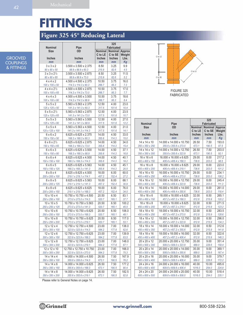
FITTINGS
www.grinnell.com 800-558-5236
GROOVEDCOUPLINGS& FITTINGS
Mechanical42
FIGURE 325
FABRICATED
Please refer to General Notes on page 14.
325Nominal Pipe Fabricated
Size OD Nominal Nominal ApproxC to LE C to SE Weight
Inches Inches Inches Inches Lbs.mm mm mm mm Kg
3 x 3 x 2 3.500 x 3.500 x 2.375 8.50 3.25 9.980 x 80 x 50 88.9 x 88.9 x 60.3 215.9 82.6 4.5
3 x 3 x 21/2 3.500 x 3.500 x 2.875 8.50 3.25 11.580 x 80 x 65 88.9 x 88.9 x 73.0 215.9 82.6 5.2
4 x 4 x 2 4.500 x 4.500 x 2.375 10.50 3.75 16.0100 x 100 x 50 114.3 x 114.3 x 60.3 266.7 95.3 7.3
4 x 4 x 21/2 4.500 x 4.500 x 2.875 10.50 3.75 17.0100 x 100 x 65 114.3 x 114.3 x 73.0 266.7 95.3 7.7
4 x 4 x 3 4.500 x 4.500 x 3.500 10.50 3.75 18.6100 x 100 x 80 114.3 x 114.3 x 88.9 266.7 95.3 8.4
5 x 5 x 2 5.563 x 5.563 x 2.375 12.50 4.00 23.0125 x 125 x 50 141.3 x 141.3 x 60.3 317.5 101.6 10.4
5 x 5 x 21/2 5.563 x 5.563 x 2.875 12.50 4.00 23.5125 x 125 x 65 141.3 x 141.3 x 73.0 317.5 101.6 10.7
5 x 5 x 3 5.563 x 5.563 x 3.500 12.50 4.00 27.0125 x 125 x 80 141.3 x 141.3 x 88.9 317.5 101.6 12.2
5 x 5 x 4 5.563 x 5.563 x 4.500 12.50 4.00 31.0125 x 125 x 100 141.3 x 141.3 x 114.3 317.5 101.6 14.1
6 x 6 x 2 6.625 x 6.625 x 2.375 14.00 4.50 33.0150 x 150 x 50 168.3 x 168.3 x 60.3 355.6 114.3 15.0
6 x 6 x 21/2 6.625 x 6.625 x 2.875 14.00 4.50 34.0150 x 150 x 65 168.3 x 168.3 x 73.0 355.6 114.3 15.4
6 x 6 x 3 6.625 x 6.625 x 3.500 14.00 4.50 37.1150 x 150 x 80 168.3 x 168.3 x 88.9 355.6 114.3 16.8
6 x 6 x 4 6.625 x 6.625 x 4.500 14.00 4.50 40.1150 x 150 x 100 168.3 x 168.3 x 114.3 355.6 114.3 18.2
6 x 6 x 5 6.625 x 6.625 x 5.563 14.00 4.50 45.1150 x 150 x 125 168.3 x 168.3 x 141.3 355.6 114.3 20.5
8 x 8 x 4 8.625 x 8.625 x 4.500 18.00 6.00 60.0200 x 200 x 100 219.1 x 219.1 x 114.1 457.2 152.4 27.2
8 x 8 x 5 8.625 x 8.625 x 5.563 18.00 6.00 68.1200 x 200 x 125 219.1 x 219.1 x 141.3 457.2 152.4 30.9
8 x 8 x 6 8.625 x 8.625 x 6.625 18.00 6.00 76.0200 x 200 x 150 219.1 x 219.1 x 168.3 457.2 152.4 34.5
10 x 10 x 4 10.750 x 10.750 x 4.500 20.50 6.50 83.1250 x 250 x 100 273.0 x 273.0 x 114.3 520.7 165.1 37.7
10 x 10 x 5 10.750 x 10.750 x 5.563 20.50 6.50 100.2250 x 250 x 125 273.0 x 273.0 x 141.3 520.7 165.1 45.5
10 x 10 x 6 10.750 x 10.750 x 6.625 20.50 6.50 106.0250 x 250 x 150 273.0 x 273.0 x 168.3 520.7 165.1 48.1
10 x 10 x 8 10.750 x 10.750 x 8.625 20.50 6.50 117.0250 x 250 x 200 273.0 x 273.0 x 219.1 520.7 165.1 53.1
12 x 12 x 4 12.750 x 12.750 x 4.500 23.00 7.00 138.0300 x 300 x 100 323.9 x 323.9 x 114.3 584.2 177.8 62.6
12 x 12 x 6 12.750 x 12.750 x 6.625 23.00 7.00 139.9300 x 300 x 150 323.9 x 323.9 x 168.3 584.2 177.8 63.5
12 x 12 x 8 12.750 x 12.750 x 8.625 23.00 7.00 148.0300 x 300 x 200 323.9 x 323.9 x 219.1 584.2 177.8 67.1
12 x 12 x 10 12.750 x 12.750 x 10.750 23.00 7.00 166.0300 x 300 x 250 323.9 x 323.9 x 273.0 584.2 177.8 75.3
14 x 14 x 4 14.000 x 14.000 x 4.500 26.50 7.50 167.9350 x 350 x 100 355.6 x 355.6 x 114.3 673.1 190.5 76.2
14 x 14 x 6 14.000 x 14.000 x 6.625 26.50 7.50 177.2350 x 350 x 150 355.6 x 355.6 x 168.3 673.1 190.5 80.4
14 x 14 x 8 14.000 x 14.000 x 8.625 26.50 7.50 182.5350 x 350 x 200 355.6 x 355.6 x 219.1 673.1 190.5 82.8
C to LE
C to LE
C to SE
325Nominal Pipe Fabricated
Size OD Nominal Nominal ApproxC to LE C to SE Weight
Inches Inches Inches Inches Lbs.mm mm mm mm Kg
14 x 14 x 10 14.000 x 14.000 x 10.750 26.50 7.50 193.0350 x 350 x 250 355.6 x 355.6 x 273.0 673.1 190.5 87.5
14 x 14 x 12 14.000 x 14.000 x 12.750 26.50 7.50 203.0350 x 350 x 300 355.6 x 355.6 x 323.9 673.1 190.5 92.1
16 x 16 x 6 16.000 x 16.000 x 6.625 29.00 8.00 217.2400 x 400 x 150 406.4 x 406.4 x 168.3 736.6 203.0 98.5
16 x 16 x 8 16.000 x 16.000 x 8.625 29.00 8.00 223.0400 x 400 x 200 406.4 x 406.4 x 219.1 736.6 203.0 101.2
16 x 16 x 10 16.000 x 16.000 x 10.750 29.00 8.00 234.1400 x 400 x 250 406.4 x 406.4 x 273.0 736.6 203.0 106.2
16 x 16 x 12 16.000 x 16.000 x 12.750 29.00 8.00 245.4400 x 400 x 300 406.4 x 406.4 x 323.9 736.6 203.0 111.3
16 x 16 x 14 16.000 x 16.000 x 14.000 29.00 8.00 261.0400 x 400 x 350 406.4 x 406.4 x 355.6 736.6 203.0 118.4
18 x 18 x 6 18.000 x 18.000 x 6.625 32.00 8.50 265.1450 x 450 x 150 457.2 x 457.2 x 168.3 812.8 215.9 120.2
18 x 18 x 8 18.000 x 18.000 x 8.625 32.00 8.50 271.5450 x 450 x 200 457.2 x 457.2 x 219.1 812.8 215.9 123.2
18 x 18 x 10 18.000 x 18.000 x 10.750 32.00 8.50 283.5450 x 450 x 250 457.2 x 457.2 x 273.0 812.8 215.9 128.6
18 x 18 x 12 18.000 x 18.000 x 12.750 32.00 8.50 296.0450 x 450 x 300 457.2 x 457.2 x 323.9 812.8 215.9 134.3
18 x 18 x 14 18.000 x 18.000 x 14.000 32.00 8.50 312.6450 x 450 x 350 457.2 x 457.2 x 355.6 812.8 215.9 141.8
18 x 18 x 16 18.000 x 18.000 x 16.000 32.00 8.50 322.6450 x 450 x 400 457.2 x 457.2 x 406.4 812.8 215.9 146.3
20 x 20 x 12 20.000 x 20.000 x 12.750 35.00 9.00 351.4500 x 500 x 300 508.0 x 508.0 x 323.9 889.0 228.6 159.4
20 x 20 x 14 20.000 x 20.000 x 14.000 35.00 9.00 369.1500 x 500 x 350 508.0 x 508.0 x 355.6 889.0 228.6 167.4
20 x 20 x 16 20.000 x 20.000 x 16.000 35.00 9.00 379.7500 x 500 x 400 508.0 x 508.0 x 406.4 889.0 228.6 172.2
24 x 24 x 16 24.000 x 24.000 x 16.000 40.00 10.00 495.6600 x 600 x 400 609.6 x 609.6 x 406.4 1016.0 254.0 224.8
24 x 24 x 20 24.000 x 24.000 x 20.000 40.00 10.00 518.4600 x 600 x 500 609.6 x 609.6 x 508.0 1016.0 254.0 235.1
Figure 325 45° Reducing Lateral

FITTINGS
www.grinnell.com800-558-5236
GROOVEDCOUPLINGS& FITTINGS
Mechanical43
FIGURE 331
FABRICATED
Please refer to General Notes on page 14.
331Nominal Pipe Fabricated
Size OD Nominal Nominal Nominal Nominal ApproxG H E1 E2 Weight
Inches Inches Inches Inches Inches Inches Lbs.mm mm mm mm mm mm Kg
4 x 3 x 3 4.500 x 3.500 x 3.500 1.63 7.38 10.75 5.63 15.9100 x 80 x 80 114.3 x 88.9 x 88.9 41.4 187.5 273.1 143.0 7.2
4 x 3 x 4 4.500 x 3.500 x 4.500 3.75 10.50 13.63 8.13 26.8100 x 80 x 100 114.3 x 88.9 x 114.3 95.3 266.7 346.2 206.5 12.2
5 x 3 x 3 5.563 x 3.500 x 3.500 1.25 9.75 11.50 6.50 24.8125 x 80 x 80 141.3 x 88.9 x 88.9 31.8 247.7 292.1 165.1 11.2
5 x 3 x 5 5.563 x 3.500 x 5.563 4.00 12.50 16.13 10.00 44.1125 x 80 x 100 141.3 x 88.9 x 141.3 101.6 317.5 409.7 254.0 20.0
5 x 4 x 3 5.563 x 4.500 x 3.500 1.88 9.13 11.88 6.88 21.1125 x 100 x 80 141.3 x 114.3 x 88.9 47.8 231.9 301.88 174.8 9.6
5 x 4 x 4 5.563 x 4.500 x 4.500 1.88 9.13 12.75 7.25 25.6125 x 100 x 100 141.3 x 114.3 x 114.3 47.8 231.9 323.9 184.2 11.6
6 x 4 x 6 6.625 x 4.500 x 6.625 4.50 14.00 18.25 11.50 62.0150 x 100 x 150 168.3 x 114.3 x 168.3 114.3 355.6 463.6 292.1 28.1
6 x 5 x 3 6.625 x 5.563 x 3.500 1.25 10.75 13.00 8.00 26.7150 x 125 x 80 168.3 x 141.3 x 88.9 31.8 273.1 330.2 203.2 12.1
6 x 5 x 4 6.625 x 5.563 x 4.500 1.25 10.75 13.88 8.38 32.0150 x 125 x 100 168.3 x 141.3 x 114.3 31.8 273.1 352.6 212.9 14.5
8 x 6 x 4 8.625 x 6.625 x 4.500 1.00 12.00 14.75 9.25 46.0200 x 150 x 100 219.1 x 168.3 x 114.1 25.4 304.8 374.7 235.0 20.9
8 x 6 x 8 8.625 x 6.625 x 8.625 6.00 18.00 23.25 15.25 93.0200 x 150 x 200 219.1 x 168.3 x 219.1 152.4 457.2 590.6 387.4 42.2
FIGURE 324
FABRICATED
Please refer to General Notes on page 14.
324Nominal Pipe Fabricated
Size OD Nominal Nominal ApproxC to LE C to SE Weight
Inches Inches Inches Inches Lbs.mm mm mm mm Kg
11/4 1.660 2.75 2.50 1.532 42.4 69.9 63.5 0.7
11/2 1.900 2.75 2.75 1.840 48.3 69.9 69.9 0.8
2 2.375 3.25 2.75 2.350 60.3 82.6 69.9 1.0
21/2 2.875 3.75 3.00 4.865 73.0 95.3 76.2 2.2
3 3.500 4.25 3.25 6.080 88.9 108.0 82.6 2.7
4 4.500 5.00 3.75 10.5100 114.3 127.0 95.3 4.8
5 5.563 5.50 4.00 15.0125 141.3 139.7 101.6 6.8
6 6.625 6.50 4.50 21.0150 168.3 165.1 114.3 9.5
8 8.625 7.75 6.00 35.0200 219.1 196.9 152.4 15.9
10 10.750 9.00 6.50 50.0250 273.0 228.6 165.1 22.7
12 12.750 10.00 7.00 87.7300 323.9 254.0 177.8 39.8
14 14.000 11.00 7.50 105.3350 355.6 279.4 190.5 47.8
Figure 324 90° True Y
Figure 331 Reducing Tee Wye
324Nominal Pipe Fabricated
Size OD Nominal Nominal ApproxC to LE C to SE Weight
Inches Inches Inches Inches Lbs.mm mm mm mm Kg
16 16.000 12.00 8.00 129.1400 406.4 304.8 203.2 58.6
18 18.000 15.50 8.50 184.4450 457.2 393.7 215.9 83.6
20 20.000 17.25 9.00 225.8500 508.0 438.2 228.6 102.4
24 24.000 20.00 10.00 308.5600 609.6 508.0 254.0 139.9

FITTINGS
www.grinnell.com 800-558-5236
GROOVEDCOUPLINGS& FITTINGS
Mechanical44
FIGURE 330
FABRICATED
H
E2
G
E1
Please refer to General Notes on page 14.
330 FabricatedNominal Pipe Nominal Nominal Nominal Nominal Approx
Size OD G H E1 E2 WeightInches Inches Inches Inches Inches Inches Lbs.mm mm mm mm mm mm Kg
2 x 2 x 2 2.375 x 2.375 x 2.375 2.75 7.00 9.00 4.63 6.550 x 50 x 50 60.3 x 60.6 x 60.6 69.9 177.8 228.6 117.6 2.9
21/2 x 21/2 x 21/2 2.875 x 2.875 x 2.875 3.00 7.75 10.50 5.75 11.665 x 65 x 65 73.0 x 73.0 x 73.0 76.2 196.9 266.7 146.1 5.3
3 x 3 x 3 3.500 x 3.500 x 3.500 3.25 8.50 11.50 6.50 16.680 x 80 x 80 88.9 x 88.9 x 88.9 82.6 215.9 292.1 165.1 7.5
4 x 4 x 3 4.500 x 4.500 x 3.500 3.75 10.50 12.88 7.88 24.0100 x 100 x 80 114.3 x 114.3 x 88.9 95.3 266.7 327.2 200.2 10.9
4 x 4 x 4 4.500 x 4.500 x 4.500 3.75 10.50 13.63 8.13 26.1100 x 100 x 100 114.3 x 114.3 x 114.3 95.3 266.7 346.2 206.5 11.8
5 x 5 x 3 5.563 x 5.563 x 3.500 4.00 12.50 14.25 9.25 32.1125 x 125 x 80 141.3 x 141.3 x 88.9 101.6 317.5 362.0 235.0 14.6
5 x 5 x 4 5.563 x 5.563 x 4.500 4.00 12.50 15.13 9.63 35.5125 x 125 x 100 141.3 x 141.3 x 114.3 101.6 317.5 384.3 244.6 16.1
5 x 5 x 5 5.563 x 5.563 x 5.563 4.00 12.50 16.13 10.00 41.0125 x 125 x 125 141.3 x 141.3 x 141.3 101.6 317.5 409.7 254.0 18.6
6 x 6 x 3 6.625 x 6.625 x 3.500 4.50 14.00 15.31 10.31 51.1150 x 150 x 80 168.3 x 168.3 x 88.9 114.3 355.6 388.9 261.9 23.2
6 x 6 x 4 6.625 x 6.625 x 4.500 4.50 14.00 16.25 10.75 55.1150 x 150 x 100 168.3 x 168.3 x 114.3 114.3 355.6 412.8 273.1 25.0
6 x 6 x 5 6.625 x 6.625 x 5.563 4.50 14.00 17.25 11.13 58.2150 x 150 x 125 168.3 x 168.3 x 141.3 114.3 355.6 438.2 282.7 26.4
6 x 6 x 6 6.625 x 6.625 x 6.625 4.50 14.00 18.25 11.50 61.0150 x 150 x 150 168.3 x 168.3 x 168.3 114.3 355.6 463.6 292.1 27.7
8 x 8 x 3 8.625 x 8.625 x 3.500 6.00 18.00 18.19 13.19 101.0200 x 200 x 80 219.1 x 219.1 x 88.9 152.4 457.2 462.0 355.0 45.8
8 x 8 x 4 8.625 x 8.625 x 4.500 6.00 18.00 19.00 13.50 111.5200 x 200 x 100 219.1 x 219.1 x 114.1 152.4 457.2 482.6 342.9 50.6
8 x 8 x 5 8.625 x 8.625 x 5.563 6.00 18.00 20.00 13.88 112.0200 x 200 x 125 219.1 x 219.1 x 141.3 152.4 457.2 508.0 352.6 50.8
8 x 8 x 6 8.625 x 8.625 x 6.625 6.00 18.00 21.13 14.38 113.0200 x 200 x 150 219.1 x 219.1 x 168.3 152.4 457.2 536.7 365.3 51.3
8 x 8 x 8 8.625 x 8.625 x 8.625 6.00 18.00 23.25 15.25 119.0200 x 200 x 200 219.1 x 219.1 x 219.1 152.4 457.2 590.6 387.4 54.0
10 x 10 x 3 10.750 x 10.750 x 3.500 6.50 20.50 19.88 14.88 131.0250 x 250 x 80 273.0 x 273.0 x 88.9 165.1 520.7 505.0 378.0 59.4
10 x 10 x 4 10.750 x 10.750 x 4.500 6.50 20.50 20.75 15.25 136.0250 x 250 x 100 273.0 x 273.0 x 114.3 165.1 520.7 527.1 387.4 61.7
10 x 10 x 5 10.750 x 10.750 x 5.563 6.50 20.50 21.88 15.75 139.0250 x 250 x 125 273.0 x 273.0 x 141.3 165.1 520.7 555.8 400.1 63.1
10 x 10 x 6 10.750 x 10.750 x 6.625 6.50 20.50 22.88 16.13 146.0250 x 250 x 150 273.0 x 273.0 x 168.3 165.1 520.7 581.2 409.7 66.2
10 x 10 x 8 10.750 x 10.750 x 8.625 6.50 20.50 27.25 19.25 155.0250 x 250 x 200 273.0 x 273.0 x 219.1 165.1 520.7 692.2 489.0 70.3
10 x 10 x 10 10.750 x 10.750 x 10.750 6.50 20.50 27.25 18.00 195.0250 x 250 x 250 273.0 x 273.0 x 273.0 165.1 520.7 692.2 457.2 88.5
12 x 12 x 3 12.750 x 12.750 x 3.500 7.00 23.00 20.75 15.75 140.0300 x 300 x 80 323.9 x 323.9 x 88.9 177.8 584.2 527.1 400.1 63.5
12 x 12 x 4 12.750 x 12.750 x 4.500 7.00 23.00 21.50 16.00 145.0300 x 300 x 100 323.9 x 323.9 x 114.3 177.8 584.2 546.1 406.4 65.8
12 x 12 x 6 12.750 x 12.750 x 6.625 7.00 23.00 23.75 17.00 165.0300 x 300 x 150 323.9 x 323.9 x 168.3 177.8 584.2 603.3 431.8 74.8
12 x 12 x 8 12.750 x 12.750 x 8.625 7.00 23.00 26.00 18.00 175.0300 x 300 x 200 323.9 x 323.9 x 219.1 177.8 584.2 660.4 457.2 79.4
12 x 12 x 10 12.750 x 12.750 x 10.750 7.00 23.00 28.00 18.75 200.0300 x 300 x 250 323.9 x 323.9 x 273.0 177.8 584.2 711.2 476.3 90.7
12 x 12 x 12 12.750 x 12.750 x 12.750 7.00 23.00 31.00 20.50 240.0300 x 300 x 300 323.9 x 323.9 x 323.9 177.8 584.2 787.4 520.7 108.9
Figure 330 Tee Wye

FITTINGS
www.grinnell.com800-558-5236
GROOVEDCOUPLINGS& FITTINGS
Mechanical45
FIGURE 341 & 342
FABRICATED
Please refer to General Notes on page 14.
341 342Nominal Pipe Nominal Fabricated Fabricated
Size OD E to E Mating Approx Mating ApproxFlange Weight Flange Weight
Inches Inches Inches Bolt Lbs. Bolt Lbs.mm mm mm Qty Kg Qty Kg
11/4 1.660 4.00 4 2.8 4 4.632 42.4 101.6 1.3 2.1
11/2 1.900 4.00 4 3.2 4 7.140 48.3 101.6 1.5 3.2
2 2.375 4.00 4 5.2 8 8.250 60.3 101.6 2.4 3.7
21/2 2.875 4.00 4 8.0 8 11.965 73.0 101.6 3.6 5.4
3 3.500 4.00 4 10.2 8 15.580 88.9 101.6 4.6 7.0
4 4.500 6.00 8 17.2 8 28.0100 114.3 152.4 7.8 12.7
5 5.563 6.00 8 21.4 8 35.0125 141.3 152.4 9.7 15.9
6 6.625 6.00 8 26.0 12 50.0150 168.3 152.4 11.8 22.7
8 8.625 6.00 8 38.4 12 73.0200 219.1 152.4 17.4 32.7
10 10.750 8.00 12 65.0 16 103.0250 273.0 203.2 29.5 46.7
12 12.750 8.00 12 91.0 16 143.0300 323.9 203.2 41.3 64.9
14 14.000 8.00 12 123.0 20 199.0350 355.6 203.2 55.8 90.3
16 16.000 8.00 12 151.0 20 255.0400 406.4 203.2 68.5 155.7
18 18.000 8.00 16 165.0 24 303.0450 457.2 203.2 74.8 137.4
20 20.000 8.00 20 205.0 24 365.0500 508.0 203.2 93.0 165.6
24 24.000 8.00 20 265.0 24 550.0600 609.6 203.2 120.2 249.5
E to E
Figure 341 Flange Adapter (ANSI Class 150 Lbs.)Figure 342 Flange Adapter (ANSI Class 300 Lbs.)

FITTINGS
www.grinnell.com 800-558-5236
GROOVEDCOUPLINGS& FITTINGS
Mechanical46
Please refer to General Notes on page 14.
407GTNominal Pipe Grooved x Threaded
Size OD Nominal ApproxEnd to End Weight
Inches Inches Inches Lbs.mm mm mm Kg
11/4 1.660 4.0 0.6
32 42.4 101.6 0.3
11/2 1.900 4.0 0.8
40 48.3 101.6 0.4
2 2.375 4.0 1.0
50 60.3 101.6 0.5
21/2 2.875 6.0 1.6
65 73.0 152.4 0.7
3 3.500 6.0 2.0
80 88.9 152.4 0.9
4 4.500 6.0 4.5
100 114.3 152.4 2.0
407TNominal Pipe Threaded x Threaded
Size OD Nominal ApproxEnd to End Weight
Inches Inches Inches Lbs.mm mm mm Kg
1/2 0.840 3.0 0.2
15 21.3 76.2 0.13/4 1.050 3.0 0.2
20 26.7 76.2 0.1
1 1.315 4.0 0.3
25 33.7 101.6 0.1
11/4 1.660 4.0 0.3
32 42.4 101.6 0.1
11/2 1.900 4.0 0.8
40 48.3 101.6 0.4
2 2.375 4.0 0.8
50 60.3 101.6 0.4
21/2 2.875 6.0 1.6
65 73.0 152.4 0.7
3 3.500 6.0 2.0
80 88.9 152.4 0.9
4 4.500 6.0 4.5
100 114.3 152.4 2.0
Clearflow® fittings protect plumbing systems through aninnovative steel-to-plastic design that establishes a dielec-tric waterway. The Clearflow line of dielectric fittingsseparates dissimilar metals in the electrolyte (waterway)eliminating the local galvanic cell.
Clearflow’s metal-to-metal joint design maintains externalelectrical continuity, thereby preventing stray currentcorrosion. This feature is critical when stray current ispresent due to intentional or non-intentional grounding ofdirect current (DC) sources, such as phone systems andappliances.
Clearflow fittings meet the requirements of ASTMstandard F-492 for continuous use at temperatures up to230°F (110°C).
Test Data/Results and Listings:
FIGURE 407GT FIGURE 407T
Figure 407GT & 407T Clearflow® Dielectric Waterway
Test data provided by Pittsburgh Testing Laboratory can be provided upon request.
®Registered Trademark of Perfection Corp.

Branch Outlets
BRAN
CH
OU
TLETS3

BRANCH OUTLETS
www.grinnell.com 800-558-5236
BRANCHOUTLETS
Mechanical48
MATERIAL SPECIFICATIONSHousing Specifications
• ASTM A-536 - Standard Specification forDuctile Iron Castings Grade 65-45-12
• Tensile Strength, minimum psi-65,000(MPa-448)
• Yield Strength, minimum psi-45,000(MPa-310)
• Elongation in 2" (50mm), minimum 12%• ASTM A-153 - Standard Specification for Hot
Dip Galvanizing
Bolt / Nut SpecificationsCarbon steel oval neck bolts and nuts are heattreated and conform to the physical properties ofASTM A-183 with a minimum tensile strength of110,000psi (758,422 kPa). Bolts and nuts are Zincelectroplated to ASTM B633.
Gold color coded metric bolts conforming to thephysical properties of ASTM F568M are availableupon request. Contact Tyco Fire & BuildingProducts.
Gasket SpecificationsGrade “E” EPDM gaskets have a green color codeidentification and conform to ASTM D-2000 forservice temperatures from -30°F (-34°C) to 230°F(110°C). They are recommended for hot water notto exceed 230°F (110°C), plus a variety of diluteacids, oil free air and many chemical services. Theyare not recommended for petroleum services.
Grade “T” Nitrile gaskets have an orange colorcode identification and conform to ASTM D-2000for service temperatures from -20°F (-29°C) to180°F (82°C). They are recommended for petro-leum products, vegetable oils, mineral oils, and airwith oil vapors.
Coatings• Orange - non lead (standard)
• RAL Red - non lead (optional)
• Hot Dipped Zinc Galvanized (optional)
The Figure 730 Mechanical Tees are rated at500 psi (34.5 Bar) on standard weight pipe and canbe used in place of a tee, a cross connection, or awelded outlet where a threaded or grooved outlet isneeded. The Mechanical Tee is ideal for use inretrofit or equipment hookup installations, as it can
Figure 730 Branch Outlet with Female
NPT/ISO 7-1 Threaded BranchFigure 730 Branch Outlet with
Grooved Branch
Various end configurations are obtainable:
Threaded x Threaded Grooved x Grooved Threaded x Grooved
be positioned along the pipe at the proper locationin the field, ensuring exact lineup of the branchoutlet connection. All Figure 730 Mechanical Teesare provided with a ductile iron lower housingsection for increased strength and dependability.This provides stability, rigidity, and inhibits damageto the pipe during tightening.
For Fire Protection Pressure Rating
and Listing / Approval information
contact Tyco Fire & Building Products.
LPCBVd S
Tech Data: G210

BRANCH OUTLETS
www.grinnell.com800-558-5236
BRANCHOUTLETS
Mechanical49
† Proper hole preparation is required for effective sealing and performance. Check the pipe seal surface
within 5/8" (15.9mm) of the hole to be certain it is free from conditions that would affect proper gasket
sealing. Remove any sharp or rough edges from the hole or upper housing contact area, that might affect
assembly, proper seating of the locating collar or flow from the outlet. For crosses, ensure double outlet
holes are aligned on opposite sides of the pipe. The use of threaded products other than steel pipe, such as
dry pendents, etc. may not be compatible with the female threaded outlet on the Mechanical Tee. Always
confirm compatibility by contacting Tyco Fire & Building Products.
‡ Maximum pressure and end load are total from all loads based on standard weight steel pipe. Pressure
ratings and end loads may differ on other pipe materials and/or wall thickness. Contact Tyco Fire & Building
Products for details.
Note: Outlet Threads conforming to ISO 7-1 are available, contact Tyco Fire & Building Products.
Please refer to General Notes on page 14.
Nominal Hole Max.‡ Nominal Tee CrossSize Dia.† End Load Dimensions Bolt Approx. Approx.
Run x Branch Hole Max. (Branch) A B C D E Size Weight WeightInches Inches Inches Lbs. Inches Inches Inches Inches Inches Inches Lbs. Lbs.
mm mm mm kN mm mm mm mm mm mm Kg Kg
2 x 1/2 1.50 1.63 277.1 2.62 4.88 3.07 2.12 1.59 3/8 x 21/4 2.2 2.650 x 15 38.1 41.3 1.2 66.5 124.0 78.0 53.8 40.4 M10 x 57 1.0 1.2
2 x 3/4 1.50 1.63 433.0 2.62 4.88 3.07 2.12 1.59 3/8 x 21/4 2.2 2.650 x 20 38.1 41.3 1.9 66.5 124.0 78.0 53.8 40.4 M10 x 57 1.0 1.2
2 x 1 1.50 1.63 679.1 2.62 4.88 3.07 2.12 1.59 3/8 x 21/4 2.2 2.650 x 25 38.1 41.3 3.0 66.5 124.0 78.0 53.8 40.4 M10 x 57 1.0 1.2
2 x 11/4 1.75 1.88 1082.1 2.78 4.88 3.32 1.93 1.59 3/8 x 21/4 2.5 3.350 x 32 44.5 47.6 4.8 70.6 124.0 84.3 49.0 40.4 M10 x 57 1.1 1.5
2 x 11/2 1.75 1.88 1417.6 2.75 4.88 3.32 1.93 1.59 3/8 x 21/4 2.5 3.750 x 40 44.5 47.6 6.3 69.9 124.0 84.3 49.0 40.4 M10 x 57 1.1 1.7
21/2 x 1/2 1.50 1.63 277.1 2.88 5.25 3.07 2.38 1.81 3/8 x 21/4 2.7 3.165 x 15 38.1 41.3 1.2 73.2 133.4 78.0 60.5 46.0 M10 x 57 1.2 1.4
21/2 x 3/4 1.50 1.63 433.0 2.88 5.25 3.07 2.38 1.81 3/8 x 21/4 2.7 3.165 x 20 38.1 41.3 1.9 73.2 133.4 78.0 60.5 46.0 M10 x 57 1.2 1.4
21/2 x 1 1.50 1.63 679.1 2.88 5.25 3.07 2.38 1.81 3/8 x 21/4 2.7 3.165 x 25 38.1 41.3 3.0 73.2 133.4 78.0 60.5 46.0 M10 x 57 1.2 1.4
21/2 x 11/4 2.00 2.13 1082.1 3.00 5.25 3.56 2.19 1.81 3/8 x 21/4 3.1 3.965 x 32 50.8 54.0 4.8 76.2 133.4 90.4 55.6 46.0 M10 x 57 1.4 1.8
21/2 x 11/2 2.00 2.13 1417.6 3.07 5.25 3.59 2.17 1.81 3/8 x 21/4 3.3 4.365 x 40 50.8 54.0 6.3 78.0 133.4 91.2 55.1 46.0 M10 x 57 1.5 1.9
21/2 x 2 2.00 2.13 2215.1 3.19 5.25 4.00 2.44 1.81 3/8 x 21/4 3.5 4.465 x 50 50.8 54.0 9.9 81.0 133.4 101.6 62.0 46.0 M10 x 57 1.6 2.0
76.1mm x 1/2 1.50 1.63 277.1 2.94 5.62 3.07 2.44 1.87 M10 x 57 2.7 3.165 x 15 38.1 41.3 1.2 74.5 142.7 78.0 62.0 47.5 1.2 1.4
76.1mm x 3/4 1.50 1.63 433.0 2.94 5.62 3.07 2.44 1.87 M10 x 57 2.7 3.165 x 20 38.1 41.3 1.9 74.5 142.7 78.0 62.0 47.5 1.2 1.4
76.1mm x 1 1.50 1.63 679.1 2.94 5.62 3.07 2.44 1.87 M10 x 57 2.7 3.165 x 25 38.1 41.3 3.0 74.5 142.7 78.0 62.0 47.5 1.2 1.4
76.1mm x 11/4 2.00 2.13 1082.1 3.06 5.62 3.56 2.25 1.87 M10 x 57 3.1 3.965 x 32 50.8 54.0 4.8 77.7 142.7 90.4 57.2 47.5 1.4 1.8
76.1mm x 11/2 2.00 2.13 1417.6 3.13 5.62 3.56 2.25 1.87 M10 x 57 3.3 5.165 x 40 50.8 54.0 6.3 79.5 142.7 90.4 57.2 47.5 1.5 2.3
76.1mm x 2 2.50 2.63 2215.1 3.25 5.62 4.00 2.50 1.87 M10 x 57 4.1 5.965 x 50 63.5 66.7 9.9 82.6 142.7 101.6 63.5 47.5 1.9 2.7
3 x 1/2 1.50 1.63 277.1 3.19 6.13 3.07 2.56 2.21 1/2 x 3 3.7 4.580 x 15 38.1 41.3 1.2 81.0 155.7 78.0 65.0 56.1 M12 x 76 1.7 2.0
3 x 3/4 1.50 1.63 433.0 3.19 6.13 3.07 2.56 2.21 1/2 x 3 3.7 4.580 x 20 38.1 41.3 1.9 81.0 155.7 78.0 65.0 56.1 M12 x 76 1.7 2.0
3 x 1 1.50 1.63 679.1 3.19 6.13 3.07 2.56 2.21 1/2 x 3 3.7 4.580 x 25 38.1 41.3 3.0 81.0 155.7 78.0 65.0 56.1 M12 x 76 1.7 2.0
3 x 11/4 1.75 1.88 1082.1 3.34 6.13 3.32 2.50 2.21 1/2 x 3 3.9 4.980 x 32 44.5 47.6 4.8 84.8 155.7 84.3 63.5 56.1 M12 x 76 1.8 2.2
3 x 11/2 2.00 2.13 1417.6 3.38 6.13 3.56 2.48 2.21 1/2 x 3 4.2 5.580 x 40 50.8 54.0 6.3 85.9 155.7 90.4 63.0 56.1 M12 x 76 1.9 2.5
3 x 2 2.50 2.63 2215.1 3.50 6.13 4.09 2.75 2.21 1/2 x 3 4.7 6.580 x 50 63.5 66.7 9.9 88.9 155.7 103.9 69.9 56.1 M12 x 76 2.1 2.9
4 x 1/2 1.50 1.63 277.1 3.69 7.13 3.07 3.06 2.78 1/2 x 3 5.5 7.1100 x 15 38.1 41.3 1.2 93.7 181.1 78.0 77.7 70.6 M12 x 76 2.5 3.2
4 x 3/4 1.50 1.63 433.0 3.69 7.13 3.07 3.06 2.78 1/2 x 3 5.5 7.1100 x 20 38.1 41.3 1.9 93.7 181.1 78.0 77.7 70.6 M12 x 76 2.5 3.2
4 x 1 1.50 1.63 679.1 3.69 7.13 3.07 3.06 2.78 1/2 x 3 5.5 7.1100 x 25 38.1 41.3 3.0 93.7 181.1 78.0 77.7 70.6 M12 x 76 2.5 3.2
4 x 11/4 1.75 1.88 1082.1 3.92 7.13 3.32 3.00 2.78 1/2 x 3 5.5 7.1100 x 32 44.5 47.6 4.8 99.6 181.1 84.3 76.2 70.6 M12 x 76 2.5 3.2
4 x 11/2 2.00 2.13 1417.6 4.00 7.13 3.56 2.98 2.78 1/2 x 3 5.5 7.1100 x 40 50.8 54.0 6.3 101.6 181.1 90.4 75.7 70.6 M12 x 76 2.5 3.2
CB
E
ADTAKEOUT
FIGURE 730 BRANCH OUTLET
WITH FEMALE NPT/ISO 7-1
THREADED BRANCH
(TEE CONFIGURATION)
CB
A
ADTAKEOUT
DTAKEOUT
FIGURE 730 BRANCH OUTLETS
WITH FEMALE NPT/ISO 7-1
THREADED BRANCH
(CROSS CONFIGURATION)
FIGURE 730 BRANCH OUTLET WITH
ONE FEMALE NPT/ISO 7-1 THREADED
BRANCH & ONE GROOVED BRANCH
(CROSS CONFIGURATION)
* see pages 51 & 52 for dimensions
*
Figure 730 Mechanical Tee - Threaded

BRANCH OUTLETS
www.grinnell.com 800-558-5236
BRANCHOUTLETS
Mechanical50
CB
E
ADTAKEOUT
FIGURE 730 BRANCH OUTLET
WITH FEMALE NPT/ISO 7-1
THREADED BRANCH
(TEE CONFIGURATION)
CB
A
ADTAKEOUT
DTAKEOUT
FIGURE 730 BRANCH OUTLETS
WITH FEMALE NPT/ISO 7-1
THREADED BRANCH
(CROSS CONFIGURATION)
FIGURE 730 BRANCH OUTLET
WITH ONE FEMALE NPT/ISO 7-1
THREADED BRANCH &
ONE GROOVED BRANCH
(CROSS CONFIGURATION)
* see pages 51 & 52
for dimensions† Proper hole preparation is required for effective sealing and performance. Check the pipe seal surface
within 5/8" (15.9mm) of the hole to be certain it is free from conditions that would affect proper gasket
sealing. Remove any sharp or rough edges from the hole or upper housing contact area, that might affect
assembly, proper seating of the locating collar or flow from the outlet. For crosses, ensure double outlet
holes are aligned on opposite sides of the pipe. The use of threaded products other than steel pipe, such
as dry pendents, etc. may not be compatible with the female threaded outlet on the Mechanical Tee. Always
confirm compatibility by contacting Tyco Fire & Building Products.
‡ Maximum pressure and end load are total from all loads based on standard weight steel pipe. Pressure
ratings and end loads may differ on other pipe materials and/or wall thickness. Contact Tyco Fire &
Building Products for details.
Note: Outlet Threads conforming to ISO 7-1 are available, contact Tyco Fire & Building Products.
Please refer to General Notes on page 14.
Nominal Hole Max.‡ Nominal Tee CrossSize Dia.† End Load Dimensions Bolt Approx. Approx.
Run x Branch Hole Max. (Branch) A B C D E Size Weight WeightInches Inches Inches Lbs. Inches Inches Inches Inches Inches Inches Lbs. Lbs.mm mm mm kN mm mm mm mm mm mm Kg Kg
4 x 2 2.50 2.63 2215.1 4.00 7.13 4.06 3.25 2.78 1/2 x 3 6.0 8.1100 x 50 63.5 66.7 9.9 101.6 181.1 103.1 82.6 70.6 M12 x 76 2.7 3.7
4 x 21/2 2.75 2.88 3245.9 4.00 7.13 4.38 3.12 2.78 1/2 x 3 6.0 8.1100 x 65 69.9 73.0 14.4 101.6 181.1 111.3 79.2 70.6 M12 x 76 2.7 3.7
4 x 76.1mm 2.75 2.88 3534.3 4.00 7.13 4.38 3.12 2.78 M12 x 76 6.0 8.1100 x 65 69.9 73.0 15.7 101.6 181.1 111.3 79.2 70.6 2.7 3.7
4 x 3 3.50 3.63 4810.6 4.13 7.13 5.13 3.31 2.78 1/2 x 3 7.0 13.5100 x 80 88.9 92.1 21.4 104.9 181.1 130.3 84.1 70.6 M12 x 76 3.2 6.1
5 x 11/2 2.00 2.13 1417.6 4.63 8.13 3.56 4.00 3.37 5/8 x 43/4 6.5 7.7125 x 40 50.8 54.0 6.3 117.6 206.5 90.4 101.6 85.6 M16 x 121 2.9 3.5
5 x 2 2.50 2.63 2215.1 4.63 8.13 4.06 3.88 3.37 5/8 x 43/4 7.1 8.1125 x 50 63.5 66.7 9.9 117.6 206.5 103.1 98.6 85.6 M16 x 121 3.2 3.7
5 x 21/2 2.75 2.88 3245.9 4.75 8.13 4.38 3.88 3.37 5/8 x 43/4 7.3 8.7125 x 65 69.9 73.0 14.4 120.7 206.5 111.3 98.6 85.6 M16 x 121 3.3 3.9
5 x 76.1mm 2.75 2.88 3534.3 4.75 8.13 4.38 3.88 3.37 M16 x 121 7.3 8.7125 x 65 69.9 73.0 15.7 120.7 206.5 111.3 98.6 85.6 3.3 3.9
5 x 3 3.50 3.63 4810.6 5.00 8.13 5.13 4.06 3.37 5/8 x 43/4 7.6 14.7125 x 80 88.9 92.1 21.4 127.0 206.5 130.3 103.1 85.6 M16 x 121 3.4 6.7
165.1mm x 11/4 2.00 2.13 1082.1 5.13 9.25 3.56 4.25 3.90 M16 x 121 6.9 7.9150 x 32 50.8 54.0 4.8 130.3 235.0 90.4 108.0 99.1 3.1 3.6
165.1mm x 11/2 2.00 2.13 1417.6 5.13 9.25 3.56 4.04 3.90 M16 x 121 7.4 8.9150 x 40 50.8 54.0 6.3 130.3 235.0 90.4 102.6 99.1 3.4 4.0
165.1mm x 2 2.50 2.63 2215.1 5.13 9.25 4.06 4.31 3.90 M16 x 121 7.5 8.9150 x 50 63.5 66.7 9.9 130.3 235.0 103.1 109.5 99.1 3.4 4.0
165.1mm x 21/2 2.75 2.88 3245.9 5.13 9.25 4.38 4.18 3.90 M16 x 121 7.5 11.1150 x 65 69.9 73.0 14.4 130.3 235.0 111.3 106.2 99.1 3.4 5.0
165.1mm x 76.1mm 2.75 2.88 3584.3 5.13 9.25 4.38 4.18 3.90 M16 x 121 7.5 11.1150 x 65 69.9 73.0 15.7 130.3 235.0 111.3 106.2 99.1 3.4 5.0
165.1mm x 3 3.50 3.63 4810.6 5.50 9.25 5.13 4.37 3.90 M16 x 121 9.5 14.1150 x 80 88.9 92.1 21.4 139.7 235.0 130.3 111.0 99.1 4.3 6.4
165.1mm x 4 4.50 4.63 7952.2 5.38 9.25 6.13 4.56 3.90 M16 x 121 10.0 20.1150 x 100 114.3 117.5 35.4 136.7 235.0 155.7 115.8 99.1 4.5 9.1
6 x 11/4 2.00 2.13 1082.1 5.13 9.25 3.56 4.25 3.90 5/8 x 43/4 6.9 7.9150 x 32 50.8 54.0 4.8 130.3 235.0 90.4 108.0 99.1 M16 x 121 3.1 3.6
6 x 11/2 2.00 2.13 1417.6 5.13 9.25 3.56 4.04 3.90 5/8 x 43/4 7.4 8.9150 x 40 50.8 54.0 6.3 130.3 235.0 90.4 102.6 99.1 M16 x 121 3.4 4.0
6 x 2 2.50 2.63 2215.1 5.13 9.25 4.06 4.31 3.90 5/8 x 43/4 7.5 8.9150 x 50 63.5 66.7 9.9 130.3 235.0 103.1 109.5 99.1 M16 x 121 3.4 4.0
6 x 21/2 2.75 2.88 3245.9 5.13 9.25 4.38 4.18 3.90 5/8 x 43/4 7.5 11.1150 x 65 69.9 73.0 14.4 130.3 235.0 111.3 106.2 99.1 M16 x 121 3.4 5.0
6 x 76.1mm 2.75 2.88 3534.3 5.13 9.25 4.38 4.18 3.90 M16 x 121 7.5 11.1150 x 65 69.9 73.0 15.7 130.3 235.0 111.3 106.2 99.1 3.4 5.0
6 x 3 3.50 3.63 4810.6 5.50 9.25 5.13 4.37 3.90 5/8 x 43/4 9.5 14.1150 x 80 88.9 92.1 21.4 139.7 235.0 130.3 111.0 99.1 M16 x 121 4.3 6.4
6 x 4 4.50 4.63 7952.2 5.38 9.25 6.13 4.56 3.90 5/8 x 43/4 10.0 20.1150 x 100 114.3 117.5 35.4 136.7 235.0 155.7 115.8 99.1 M16 x 121 4.5 9.1
8 x 21/2 2.75 2.88 3245.9 6.25 12.50 4.38 5.12 4.90 3/4 x 43/4 10.2 12.1200 x 65 69.9 73.0 14.4 158.8 317.5 111.3 130.0 124.5 M20 x 121 4.6 5.5
8 x 76.1mm 2.75 2.88 3534.3 6.25 12.50 4.38 5.12 4.90 M20 x 121 10.2 12.1200 x 65 69.9 73.0 15.7 158.8 317.5 111.3 130.0 124.5 4.6 5.5
8 x 3 3.50 3.63 4810.6 6.50 12.50 5.13 5.37 4.90 3/4 x 43/4 12.5 15.1200 x 80 88.9 92.1 21.4 165.1 317.5 130.3 136.4 124.5 M20 x 121 5.7 6.8
8 x 4 4.50 4.63 7952.2 6.38 12.50 6.13 5.56 4.90 3/4 x 43/4 12.5 21.1200 x 100 114.3 117.5 35.4 162.1 317.5 155.7 141.2 124.5 M20 x 121 5.7 9.6
*
Figure 730 Mechanical Tee - Threaded

BRANCH OUTLETS
www.grinnell.com800-558-5236
BRANCHOUTLETS
Mechanical51
Nominal Hole Max.‡ Nominal Tee CrossSize Dia.† End Load Dimensions Bolt Approx. Approx.
Run x Branch Hole Max. (Branch) A B C E Size Weight WeightInches Inches Inches Lbs. Inches Inches Inches Inches Inches Lbs. Lbs.mm mm mm kN mm mm mm mm mm Kg Kg
2 x 11/4 1.75 1.88 1082.1 2.78 4.88 3.32 1.59 3/8" x 21/4" 2.5 3.350 x 32 44.5 47.6 4.8 70.6 124.0 84.3 40.4 M10 x 57 1.1 1.5
2 x 11/2 1.75 1.88 1417.6 2.62 4.88 3.32 1.59 3/8" x 21/4" 2.5 3.750 x 40 44.5 47.6 6.3 66.5 124.0 84.3 40.4 M10 x 57 1.1 1.7
21/2 x 11/4 2.00 2.13 1082.1 3.00 5.25 3.56 1.81 3/8" x 21/4" 3.1 3.965 x 32 50.8 54.0 4.8 76.2 133.4 90.4 46.0 M10 x 57 1.4 1.8
21/2 x 11/2 2.00 2.13 1417.6 3.07 5.25 3.59 1.81 3/8" x 21/4" 3.3 4.365 x 40 50.8 54.0 6.3 78.0 133.4 91.2 46.0 M10 x 57 1.5 1.9
21/2 x 2 2.00 2.13 2215.1 3.19 5.25 4.00 1.81 3/8" x 21/4" 3.5 4.465 x 50 50.8 54.0 9.9 81.0 133.4 101.6 46.0 M10 x 57 1.6 2.0
76.1mm x 11/4 2.00 2.13 1082.1 3.06 5.62 3.56 1.87 M10 x 57 3.1 3.965 x 32 50.8 54.0 4.8 77.7 142.7 90.4 47.5 1.4 1.8
76.1mm x 11/2 2.00 2.13 1417.6 3.13 5.62 3.56 1.87 M10 x 57 3.3 5.165 x 40 50.8 54.0 6.3 79.5 142.7 90.4 47.5 1.5 2.3
76.1mm x 2 2.50 2.63 2215.1 3.25 5.62 4.00 1.87 M10 x 57 4.1 5.965 x 50 63.5 66.7 9.9 82.6 142.7 101.6 47.5 1.9 2.7
3 x 11/4 1.75 1.88 1082.1 3.34 6.13 3.32 2.21 1/2" x 3" 3.9 4.980 x 32 44.5 47.6 4.8 84.8 155.7 84.3 56.1 M12 x 76 1.8 2.2
3 x 11/2 2.00 2.13 1417.6 3.38 6.13 3.56 2.21 1/2" x 3" 4.2 5.580 x 40 50.8 54.0 6.3 85.9 155.7 90.4 56.1 M12 x 76 1.9 2.5
3 x 2 2.50 2.63 2215.1 3.50 6.13 4.09 2.21 1/2" x 3" 4.7 6.580 x 50 63.5 66.7 9.9 88.9 155.7 103.9 56.1 M12 x 76 2.1 2.9
4 x 11/4 1.75 1.88 1082.1 3.92 7.13 3.32 2.78 1/2" x 3" 5.5 7.1100 x 32 44.5 47.6 4.8 99.6 181.1 84.3 70.6 M12 x 76 2.5 3.2
4 x 11/2 2.00 2.13 1417.6 4.00 7.13 3.56 2.78 1/2" x 3" 5.5 7.1100 x 40 50.8 54.0 6.3 101.6 181.1 90.4 70.6 M12 x 76 2.5 3.2
4 x 2 2.50 2.63 2215.1 4.00 7.13 4.06 2.78 1/2" x 3" 6.0 8.1100 x 50 63.5 66.7 9.9 101.6 181.1 103.1 70.6 M12 x 76 2.7 3.7
4 x 21/2 2.75 2.88 3245.9 4.00 7.13 4.38 2.78 1/2" x 3" 6.0 8.1100 x 65 69.9 73.0 14.4 101.6 181.1 111.3 70.6 M12 x 76 2.7 3.7
4 x 76.1mm 2.75 2.88 3534.3 4.00 7.13 4.38 2.78 M12 x 76 6.0 8.1100 x 65 69.9 73.0 15.7 101.6 181.1 111.3 70.6 2.7 3.7
4 x 3 3.50 3.63 4810.6 4.13 7.13 5.13 2.78 1/2" x 3" 7.0 13.5100 x 80 88.9 92.1 21.4 104.9 181.1 130.3 70.6 M12 x 76 3.2 6.1
5 x 11/2 2.00 2.13 1417.6 4.63 8.13 3.56 3.37 5/8" x 43/4" 6.5 7.7125 x 40 50.8 54.0 6.3 117.6 206.5 90.4 85.6 M16 x 121 2.9 3.5
5 x 2 2.50 2.63 2215.1 4.63 8.13 4.06 3.37 5/8" x 43/4" 7.1 8.1125 x 50 63.5 66.7 9.9 117.6 206.5 103.1 85.6 M16 x 121 3.2 3.7
5 x 21/2 2.75 2.88 3245.9 4.75 8.13 4.38 3.37 5/8" x 43/4" 7.3 8.7125 x 65 69.9 73.0 14.4 120.7 206.5 111.3 85.6 M16 x 121 3.3 3.9
† Proper hole preparation is required for effective sealing and performance. Check the pipe seal
surface within 5/8" (15.9mm) of the hole to be certain it is free from conditions that would affect
proper gasket sealing. Remove any sharp or rough edges from the hole or upper housing contact
area, that might affect assembly, proper seating of the locating collar or flow from the outlet. For
crosses, ensure double outlet holes are aligned on opposite sides of the pipe.
‡ Maximum pressure and end load are total from all loads based on standard weight steel pipe.
Pressure ratings and end loads may differ on other pipe materials and/or wall thickness. Contact
Tyco Fire & Building Products for details.
Please refer to General Notes on page 14.
FIGURE 730 BRANCH OUTLET WITH
GROOVED BRANCH
(TEE CONFIGURATION)
FIGURE 730 BRANCH OUTLETS WITH
GROOVED BRANCH
(CROSS CONFIGURATION)
FIGURE 730 BRANCH OUTLET WITH
ONE FEMALE NPT/ISO 7-1 THREADED
BRANCH & ONE GROOVED BRANCH
(CROSS CONFIGURATION)
* see pages 49 & 50 for dimensions
*
CB
A
A
CB
A
E
*
Figure 730 Mechanical Tee - Grooved

BRANCH OUTLETS
www.grinnell.com 800-558-5236
BRANCHOUTLETS
Mechanical52
FIGURE 730 BRANCH OUTLET WITH
GROOVED BRANCH
(TEE CONFIGURATION)
FIGURE 730 BRANCH OUTLETS WITH
GROOVED BRANCH
(CROSS CONFIGURATION)
FIGURE 730 BRANCH OUTLET WITH
ONE FEMALE NPT/ISO 7-1 THREADED
BRANCH & ONE GROOVED BRANCH
(CROSS CONFIGURATION)
* see pages 49 & 50 for dimensions
CB
A
A
CB
A
E
† Proper hole preparation is required for effective sealing and performance. Check the pipe seal
surface within 5/8" (15.9mm) of the hole to be certain it is free from conditions that would affect
proper gasket sealing. Remove any sharp or rough edges from the hole or upper housing contact
area, that might affect assembly, proper seating of the locating collar or flow from the outlet. For
crosses, ensure double outlet holes are aligned on opposite sides of the pipe.
‡ Maximum pressure and end load are total from all loads based on standard weight steel pipe.
Pressure ratings and end loads may differ on other pipe materials and/or wall thickness. Contact
Tyco Fire & Building Products for details.
Please refer to General Notes on page 14.
Nominal Hole Max.‡ Nominal Tee CrossSize Dia.† End Load Dimensions Bolt Approx. Approx.
Run x Branch Hole Max. (Branch) A B C E Size Weight WeightInches Inches Inches Lbs. Inches Inches Inches Inches Inches Lbs. Lbs.
mm mm mm kN mm mm mm mm mm Kg Kg
5 x 76.1mm 2.75 2.88 3534.3 4.75 8.13 4.38 3.37 M16 x 121 7.3 8.7125 x 65 69.9 73.0 15.7 120.7 206.5 111.3 85.6 3.3 3.9
5 x 3 3.50 3.63 4810.6 5.00 8.13 5.13 3.37 5/8" x 43/4" 7.6 14.7125 x 80 88.9 92.1 21.4 127.0 206.5 130.3 85.6 M16 x 121 3.4 6.7
165.1mm x 11/4 2.00 2.13 1082.1 5.13 9.25 3.56 3.90 M16 x 121 6.9 7.9150 x 32 50.8 54.0 4.8 130.3 235.0 90.4 99.1 3.1 3.6
165.1mm x 11/2 2.00 2.13 1417.6 5.13 9.25 3.56 3.90 M16 x 121 7.4 8.9150 x 40 50.8 54.0 6.3 130.3 235.0 90.4 99.1 3.4 4.0
165.1mm x 2 2.50 2.63 2215.1 5.13 9.25 4.06 3.90 M16 x 121 7.5 8.9150 x 50 63.5 66.7 9.9 130.3 235.0 103.1 99.1 3.4 4.0
165.1mm x 21/2 2.75 2.88 3245.9 5.13 9.25 4.38 3.90 M16 x 121 7.5 11.1150 x 65 69.9 73.0 14.4 130.3 235.0 111.3 99.1 3.4 5.0
165.1mm x 76.1mm2.75 2.88 3534.3 5.13 9.25 4.38 3.90 M16 x 121 7.5 11.1150 x 65 69.9 73.0 15.7 130.3 235.0 111.3 99.1 3.4 5.0
165.1mm x 3 3.50 3.63 4810.6 5.50 9.25 5.13 3.90 M16 x 121 9.5 14.1150 x 80 88.9 92.1 21.4 139.7 235.0 130.3 99.1 4.3 6.4
165.1mm x 4 4.50 4.63 7952.2 5.38 9.25 6.13 3.90 M16 x 121 10.0 20.1150 x 100 114.3 117.5 35.4 136.7 235.0 155.7 99.1 4.5 9.1
6 x 11/4 2.00 2.13 1082.1 5.13 9.25 3.56 3.90 5/8" x 43/4" 6.9 7.9150 x 32 50.8 54.0 4.8 130.3 235.0 90.4 99.1 M16 x 121 3.1 3.6
6 x 11/2 2.00 2.13 1417.6 5.13 9.25 3.56 3.90 5/8" x 43/4" 7.4 8.9150 x 40 50.8 54.0 6.3 130.3 235.0 90.4 99.1 M16 x 121 3.4 4.0
6 x 2 2.50 2.63 2215.1 5.13 9.25 4.06 3.90 5/8" x 43/4" 7.5 8.9150 x 50 63.5 66.7 9.9 130.3 235.0 103.1 99.1 M16 x 121 3.4 4.0
6 x 21/2 2.75 2.88 3245.9 5.13 9.25 4.38 3.90 5/8" x 43/4" 7.5 11.1150 x 65 69.9 73.0 14.4 130.3 235.0 111.3 99.1 M16 x 121 3.4 5.0
6 x 76.1mm 2.75 2.88 3534.3 5.13 9.25 4.38 3.90 M16 x 121 7.5 11.1150 x 65 69.9 73.0 15.7 130.3 235.0 111.3 99.1 3.4 5.0
6 x 3 3.50 3.63 4810.6 5.50 9.25 5.13 3.90 5/8" x 43/4" 9.5 14.1150 x 80 88.9 92.1 21.4 139.7 235.0 130.3 99.1 M16 x 121 4.3 6.4
6 x 4 4.50 4.63 7952.2 5.38 9.25 6.13 3.90 5/8" x 43/4" 10.0 20.1150 x 100 114.3 117.5 35.4 136.7 235.0 155.7 99.1 M16 x 121 4.5 9.1
8 x 21/2 2.75 2.88 3245.9 6.25 12.50 4.38 4.90 3/4" x 43/4" 10.2 12.1200 x 65 69.9 73.0 14.4 158.8 317.5 111.3 124.5 M20 x 121 4.6 5.5
8 x 76.1mm 2.75 2.88 3534.3 6.25 12.50 4.38 4.90 M20 x 121 10.2 12.1200 x 65 69.9 73.0 15.7 158.8 317.5 111.3 124.5 4.6 5.5
8 x 3 3.50 3.63 4810.6 6.50 12.50 5.13 4.90 3/4" x 43/4" 12.5 15.1200 x 80 88.9 92.1 21.4 165.1 317.5 130.3 124.5 M20 x 121 5.7 6.8
8 x 4 4.50 4.63 7952.2 6.38 12.50 6.13 4.90 3/4" x 43/4" 12.5 21.1200 x 100 114.3 117.5 35.4 162.1 317.5 155.7 124.5 M20 x 121 5.7 9.6
*
Figure 730 Mechanical Tee - Grooved

Valves
VALV
ES4

BUTTERFLY VALVES
www.grinnell.com 800-558-5236
VALVES
Mechanical54
Model B302Grinnell® Model B302 Butterfly Valves are capable ofpressures of 300 psi (20.7 Bar) for sizes 2" - 8"(60.3mm - 219.1mm) and 200 psi for sizes 10" and 12"(273.0mm and 323.9mm). The valves are designed forefficient control of: on/off or throttling/balancingservice, fluid flow and “bubble tight” shut off in pipingsystems. Flow may be from either direction and the valvemay be positioned in any orientation. The valves areavailable with either a Gear Operator, for sizes 2" - 12"(60.3mm - 323.9mm) or Lever-Lock Operator, for sizes2" - 8" (60.3mm - 219.1mm). The valves are furnishedwith grooved ends for use with grooved couplings andcan be easily adapted to flanged components utilizingGrinnell Figure 71 Class 150 Flange Adapters.
The body and disc construction provides for increasedstrength and durability. The disc seal and body coatingsare compatible with a variety of chemicals and tempera-ture ranges (Contact Tyco Fire & Building Products forspecific recommendations on seal and coating selec-tions).
The Model B302 Butterfly Valve with Gear Operator isa self-locking worm gear type. It is equipped withadjustable stops at the open and shut positions.
The Model B302 Butterfly Valve with Lever-LockOperator has a throttling plate which provides throttlingnotches every 10° for manual control in balancing up to90° or shut off service. The lever may be padlocked inany one of the positions including opened or closed byvirtue of a locking hole located in the handle and lever.
Model B302 with Lever-Lock Operator
Model B302 with Gear Operator
Tech Data: G310

BUTTERFLY VALVES
www.grinnell.com800-558-5236
Mechanical
VALVES
55
Model B302 Grooved End Butterfly Valve with Gear OperatorNominal Nominal Dimensions Approx.
Size A B C D E F G Weight
Inches Inches Inches Inches Inches Inches Inches Inches Lbs.
mm mm mm mm mm mm mm mm Kg
2 8.46 3.14 7.64 2.89 3.33 N/A* 5.50 14.550 214.9 79.8 194.1 73.4 84.6 139.7 6.6
21/2 8.65 3.25 7.64 3.46 3.85 N/A* 5.69 15.565 219.7 82.6 194.1 87.9 97.8 144.5 7.0
3 8.99 3.54 7.64 3.97 3.85 N/A* 5.94 17.080 226.1 89.9 194.1 100.8 97.8 150.9 7.7
4 9.79 4.35 7.64 5.03 4.56 N/A* 8.00 20.5100 248.7 110.5 194.1 127.8 115.8 203.2 9.3
5 9.30 4.84 7.64 6.28 5.86 N/A* 7.33 25.0125 236.2 122.9 194.1 159.3 148.8 186.2 11.3
6 13.53 5.93 9.53 7.25 5.86 N/A* 8.61 33.0150 343.7 150.6 242.1 184.2 148.8 218.7 15.0
8 14.47 6.87 9.53 9.25 5.26 1.30 9.55 45.0200 367.5 174.5 242.1 235.0 133.6 33.0 242.6 20.4
10 16.53 9.17 11.54 11.25 6.29 1.65 11.61 83.0250 418.9 232.9 293.1 285.8 159.8 41.9 294.9 37.6
12 17.52 10.17 11.54 13.14 6.52 2.56 12.60 100.0300 445.0 258.3 293.1 333.8 165.6 65.0 320.0 45.4
2" 3" 6" 8"2 /2"
1000
0
5000
4000
3000
2000
100050
0
400
300
200
100
5040302010
0.1
0.2
0.3
0.5
0.4
1
2
3
4
5
4" 10"
12"
3000
0
2000
0
FLOW RATE (GPM)
PR
ES
SU
RE
DR
OP
IN P
SI
1
5"
MATERIAL SPECIFICATIONS
PERFORMANCE* End of disc does not extend beyond valve body.
Please refer to General Notes on page 14.
Note: It is good piping practice to apply a safety factor of 15% to 20%
to the values in the above table.
Ductile Iron Body andDisc Specifications
• ASTM A-395 - Standard Specification for Ductile Iron Castings• Grade 60-40-18• Tensile Strength, minimum psi-60,000 (MPa-414)• Yield Strength, minimum psi-40,000 (MPa-276)• Elongation in 2" (50mm), minimum 18%
Body Coating Black Polymid Coated
Upper and Lower StemType 416 Stainless Steel
Gear Operator Cast Iron Housing
Disc Seal SpecificationsEncapsulated Rubber
EPDM - for service temperatures from-20°F (-29°C) to 250°F (121°C), intermittentservice at 250°F (121°C) and continuous service at225°F (107°C). They are recommended for hotwater not to exceed the temperature ratings above,plus a variety of dilute acids, alkalines and manychemical services. They are not recommended forpetroleum oil, strong acid, strong alkaline orcompressed air services.
Nitrile - for service temperatures from-20°F (-29°C) to 180°F (82°C). They are recom-mended for solvents, oils, water and hydraulic fluidreisitance. They are not recommended for highlypolar solvents such as acetone and methyl ethylketone, cholrinated hydrocarbons, ozone or nitrohydrocarbons and some aviation fuels.
Front view
with valve open
Side view
with valve open
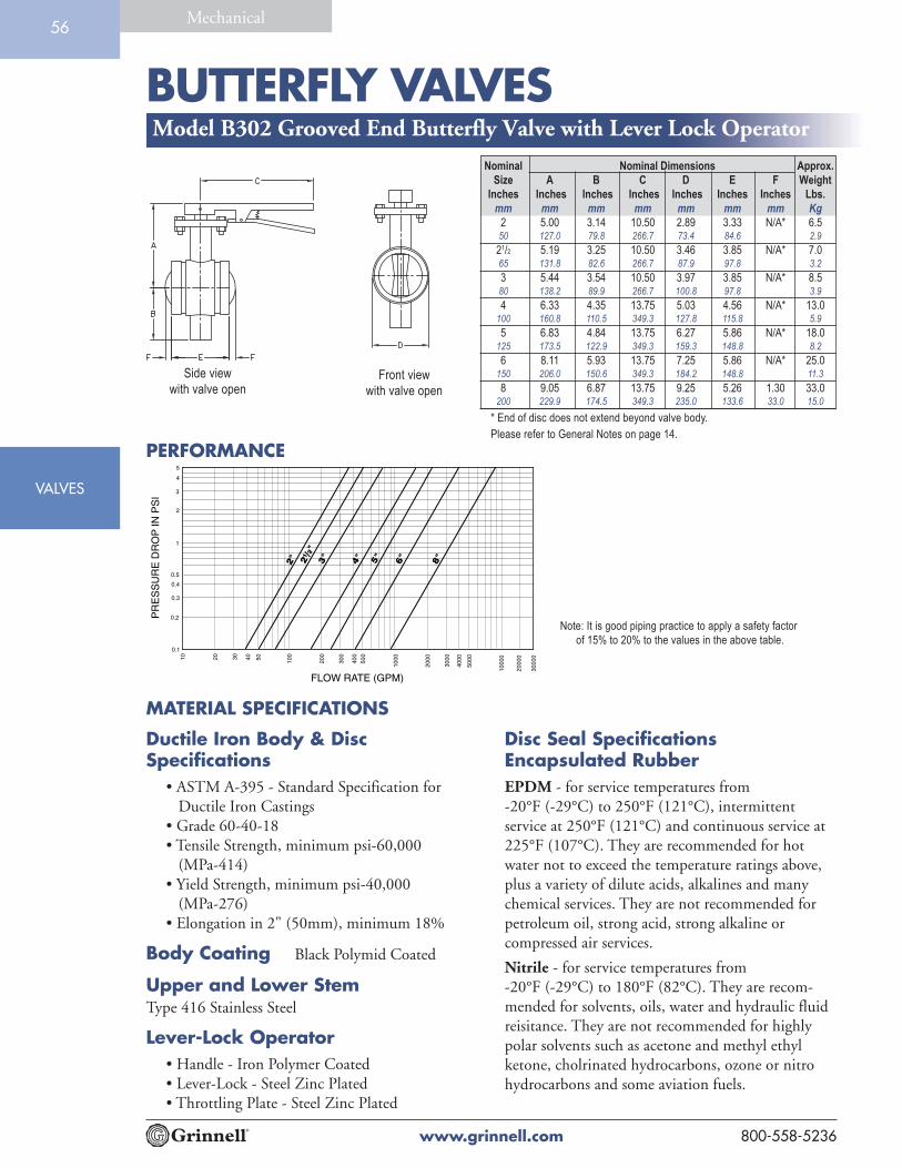
BUTTERFLY VALVES
www.grinnell.com 800-558-5236
VALVES
Mechanical56
Model B302 Grooved End Butterfly Valve with Lever Lock Operator
Nominal Nominal Dimensions Approx.
Size A B C D E F Weight
Inches Inches Inches Inches Inches Inches Inches Lbs.
mm mm mm mm mm mm mm Kg
2 5.00 3.14 10.50 2.89 3.33 N/A* 6.550 127.0 79.8 266.7 73.4 84.6 2.9
21/2 5.19 3.25 10.50 3.46 3.85 N/A* 7.065 131.8 82.6 266.7 87.9 97.8 3.2
3 5.44 3.54 10.50 3.97 3.85 N/A* 8.580 138.2 89.9 266.7 100.8 97.8 3.9
4 6.33 4.35 13.75 5.03 4.56 N/A* 13.0100 160.8 110.5 349.3 127.8 115.8 5.9
5 6.83 4.84 13.75 6.27 5.86 N/A* 18.0125 173.5 122.9 349.3 159.3 148.8 8.2
6 8.11 5.93 13.75 7.25 5.86 N/A* 25.0150 206.0 150.6 349.3 184.2 148.8 11.3
8 9.05 6.87 13.75 9.25 5.26 1.30 33.0200 229.9 174.5 349.3 235.0 133.6 33.0 15.0
* End of disc does not extend beyond valve body.
Please refer to General Notes on page 14.
Front view
with valve open
Side view
with valve open
2" 3" 6" 8"2 /2"
1000
0
5000
4000
3000
2000
100050
0
400
300
200
100
5040302010
0.1
0.2
0.3
0.5
0.4
1
2
3
4
5
4"
3000
0
2000
0
FLOW RATE (GPM)
PR
ES
SU
RE
DR
OP
IN P
SI
1
5"
MATERIAL SPECIFICATIONS
PERFORMANCE
Note: It is good piping practice to apply a safety factor
of 15% to 20% to the values in the above table.
Ductile Iron Body & DiscSpecifications
• ASTM A-395 - Standard Specification for Ductile Iron Castings• Grade 60-40-18• Tensile Strength, minimum psi-60,000 (MPa-414)• Yield Strength, minimum psi-40,000 (MPa-276)• Elongation in 2" (50mm), minimum 18%
Body Coating Black Polymid Coated
Upper and Lower StemType 416 Stainless Steel
Lever-Lock Operator• Handle - Iron Polymer Coated• Lever-Lock - Steel Zinc Plated• Throttling Plate - Steel Zinc Plated
Disc Seal SpecificationsEncapsulated RubberEPDM - for service temperatures from-20°F (-29°C) to 250°F (121°C), intermittentservice at 250°F (121°C) and continuous service at225°F (107°C). They are recommended for hotwater not to exceed the temperature ratings above,plus a variety of dilute acids, alkalines and manychemical services. They are not recommended forpetroleum oil, strong acid, strong alkaline orcompressed air services.
Nitrile - for service temperatures from-20°F (-29°C) to 180°F (82°C). They are recom-mended for solvents, oils, water and hydraulic fluidreisitance. They are not recommended for highlypolar solvents such as acetone and methyl ethylketone, cholrinated hydrocarbons, ozone or nitrohydrocarbons and some aviation fuels.

BUTTERFLY VALVES
www.grinnell.com800-558-5236
Mechanical
VALVES
57
Model 308 14" - 24" Butterfly ValveThe Model 308 Butterfly Valve provides dependable,long-term service and superior control of fluid flow inpiping systems. Flow may be from either direction and thevalve may be positioned in any orientation. The valve isfurnished with grooved ends for use with grooved cou-plings. The body and disc design provides exceptionalflow characteristics and low operating torque. The disc hasa streamline profile that optimizes flow. The body is linedwith an elastomer seat that is reinforced with a phenolicbacking ring, reducing seat distortion, and wear.
The Model 308 Butterfly Valve is provided with a gearoperator with adjustable stops at the open and shut positions. Tech Data: G320
Maximum Working Pressure is 150 psi (10.3 Bar) with 316 S.S. Stemand 200 psi (13.8 Bar) with 416 S.S. Stem. Special order is availableupon request: Vacuum Service to 29.5" (750mm) Hg.
Temperature rating for Grade E EPDM seat material is -40°F (-40°C)to +230°F (+110°C), recommended for water service, dilute acids,alkalies, oil-free air and many chemical services. NOT RECOM-MENDED FOR USE IN PETROLEUM SERVICES. The tempera-ture rating for Grade T (Nitrile) seat material is -20°F (-29°C) to+180°F (+82°C), recommended for petroleum products, air with oilvapors, vegetable oils and mineral oils. NOT RECOMMENDEDFOR USE IN HOT WATER SERVICES. (Contact Tyco Fire &Building Products for specific recommendations on seat material.)

BUTTERFLY VALVES
www.grinnell.com 800-558-5236
VALVES
Mechanical58
MATERIAL SPECIFICATIONSBody
• Cast Iron conforming to ASTM A-126,Class B
Body Seat (Liner)• Grade E EPDM, Grade T Nitrile or Viton®
Body CoatingEpoxy Coated
Disc• Stainless Steel conforming to ASTM A-351,
Grade CF8M• Aluminum Bronze conforming to
ASTM B-148, C95400• Ductile Iron conforming to ASTM A-536
Grade 65-45-12
Drive and Bottom ShaftStainless Steel conforming to ASTM A-582,Type 416 or Stainless Steel conforming toASTM A-276, Type 316
Gear OperatorCast Iron Housing
Upper and Lower BearingsReinforced Teflon
PlugCast Iron ASTM A-126
Viton® is an E.I. Dupont trademark
PERFORMANCE
16"
18"
1000
0
5000
4000
3000
2000
100050
0
400
300
200
1005040302010
0.1
0.2
0.3
0.5
0.4
1
2
3
4
5
20"
24"
3000
0
2000
0
FLOW RATE (GPM)
PR
ES
SU
RE
DR
OP
IN P
SI
1000
00
5000
0
4000
0
14"
Note: It is good piping practice to apply a safety factor of 15% to 20% to the values in the
above table for design purposes.
Nominal Nominal Dimensions Approx.
Size A B C D E F Weight
Inches Inches Inches Inches Inches Inches Inches Lbs.
mm mm mm mm mm mm mm Kg
14 23.25 10.75 10.00 21.00 13.06 15.25 378.0350 590.6 273.1 254.0 533.4 331.7 387.4 171.8
16 24.75 12.50 10.00 23.50 14.33 16.75 452.0400 628.7 317.5 254.0 596.9 364.0 425.5 205.5
18 25.75 14.00 10.00 25.00 15.40 17.75 548.0450 654.1 355.6 254.0 635.0 391.2 450.9 249.1
20 27.25 15.00 10.00 27.50 16.38 18.25 728.0500 692.2 381.0 254.0 698.5 416.1 463.6 330.9
24 30.12 16.75 10.25 32.00 18.26 21.12 1097.0600 765.0 425.5 260.4 812.8 463.8 536.4 498.6
Model 308 14" - 24" Butterfly Valve

BUTTERFLY VALVES
www.grinnell.com800-558-5236
Mechanical
VALVES
59
Model B8101 Low Profile Butterfly Valve
MATERIAL SPECIFICATIONS
Body• Ductile Iron
Body CoatingBlack Epoxy Coated
DiscDuctile Iron
Disc SealEPDM encapsulated rubber
StemTwo-piece Stainless Steel, splined
Stem SealO-rings, upper and lower stem
HandleCarbon Steel zinc plated
The Model B8101 Low Profile Butterfly Valve hasa rated working pressure of 200 PSI and providesefficient control of fluid in piping systems. Flowmay be from either direction, and the valve maybe positioned in any orientation. The ductile ironbody is epoxy coated to resist atmosphericcorrosion and the disc is EPDM encapsulatedductile iron to be compatible with a variety ofchemicals and temperature ranges.
A
B
C
D
EF
Tech Data: G330
Nominal
Size A B C D E F
Inches Inches Inches Inches Inches Inches Inches
mm mm mm mm mm mm
2 3.39 5.98 0.98 1.81 1.97 3.1550 86.0 152.0 25.0 46.0 50.0 80.0
21/2 3.78 5.98 0.98 2.05 2.40 3.5865 96.0 152.0 25.0 52.0 61.0 91.0
3 3.78 8.27 0.98 2.56 2.64 4.2180 96.0 210.0 25.0 65.0 67.0 107.0
4 4.53 8.27 0.98 3.27 3.27 4.84100 115.0 210.0 25.0 83.0 83.0 123.0
6 5.20 12.01 1.26 4.29 4.29 6.85150 132.0 305.0 32.0 109.0 109.0 174.0
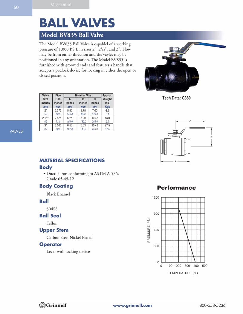
BALL VALVES
www.grinnell.com 800-558-5236
VALVES
Mechanical60
Model BV835 Ball ValveThe Model BV835 Ball Valve is capablel of a workingpressure of 1,000 P.S.I. in sizes 2", 21/2", and 3". Flowmay be from either direction and the vavles may bepositioned in any orientation. The Model BV835 isfurnished with grooved ends and features a handle thataccepts a padlock device for locking in either the open orclosed position.
MATERIAL SPECIFICATIONSBody
• Ductile iron conforming to ASTM A-536,Grade 65-45-12
Body CoatingBlack Enamel
Ball304SS
Ball SealTeflon
Upper StemCarbon Steel Nickel Plated
OperatorLever with locking device
A
B
C
Performance
0 100 200 300 400 500
TEMPERATURE (°F)
300
600
900
1200
0
)IS
P(E
RU
SS
ER
P
Tech Data: G380Valve Pipe Nominal Size Approx.
Size O.D. A B C Weight
Inches Inches Inches Inches Inches lbs.
mm mm mm mm mm Kgs
2" 2.375 5.50 3.75 7.00 6.950 60.3 140.0 95.0 178.0 3.1
2 1/2" 2.875 6.25 5.20 10.43 13.065 73.0 159.0 132.0 265.0 5.9
3" 3.500 6.56 5.63 10.43 27.580 88.9 167.0 143.0 265.0 12.5

VALVES
CHECK VALVES
www.grinnell.com800-558-5236
Mechanical61
Grinnell® Model 590 Check Valves are capable of pressures up to300 psi (20.7 Bar) and are designed as compact and rugged swing-type units that allow water flow in one direction and prevent flow inthe opposite direction. They are manufactured with a ductile ironbody, nickel seat and a stainless steel clapper assembly for sizes 2"-8"(60.3mm - 219.1 mm), and a ductile iron clapper assembly for sizes10"-12" (273.0mm - 323.9 mm). A resilient elastomer seal facing onthe spring loaded clapper ensures a leak tight seal and a non-stickingoperation. All Model 590 Check Valves are designed to minimizewater hammer caused by flow reversal.
The valves are furnished with grooved ends and can be installedusing grooved couplings. The Model 590 can be installed withANSI class 150 Flanges utilizing our Figure 71 flange adapters andalso ANSI class 300 Flange Adapters. All Model 590 Check Valveshave been designed with a removable cover for ease of field mainte-nance. They may be installed in either horizontal or vertical pipingsystems with the flow in the upward or downward direction.
MATERIAL SPECIFICATIONS
Ductile Iron Body &Cap Specifications
• ASTM A-536 - Standard Specification forDuctile Iron Castings Grade 65-45-12
• Tensile Strength, minimum psi-65,000(MPa-448)
• Yield Strength, minimum psi-45,000(MPa-310)
• Elongation in 2" (50mm), minimum 12%
SeatNickel
CoatingNon-lead paint
Model 590 Grooved End Check Valve
Tech Data: G350
Seal SpecificationsGrade “E” EPDM seals have a green color codeidentification and conform to ASTM D-2000for service temperatures from -30°F (-34°C) to230°F (110°C). They are recommended for hotwater not to exceed 230°F (110°C), plus avariety of dilute acids, oil free air and manychemical services. They are not recommendedfor petroleum services.
Grade “T” Nitrile seals have an orange colorcode identification and conform to ASTMD-2000 for service temperatures from-20°F (-29°C) to 180°F (82°C). They arerecommended for petroleum products, veg-etable oils, mineral oils, and air with oil vapors.

CHECK VALVES
www.grinnell.com 800-558-5236
VALVES
Mechanical62
Please refer to General Notes on page 14.
2.5"
/76.
1mm 4"
165.
1mm
/6" 8"3"
1000
0
5000
4000
3000
2000
100050
0
400
300
200
100
5040302010
0.1
0.2
0.3
0.5
0.4
1
2
3
4
5
139.
7mm
/5"
10"
12"
2000
0
3784
8
1892
4
1513
9.2
1135
4.4
7569
.6
3784
.8
1892
.415
13.9
1135
.5
757.
0
378.
5
189.
2
151.
4
113.
5
75.7
37.8
7570
0
2"
FLOW RATE (LPM)
FLOW RATE IN G.P.M.
PRES
SURE
DRO
P IN
PSI
PERFORMANCE
Note: It is good piping practice to apply a safety factor of 15% to 20% to the values in the above table.
Nominal Nominal Dimensions Cover Approx.
Size A B C D E Bolt Weight
Inches Inches Inches Inches Inches Inches Torque Lbs.
mm mm mm mm mm mm Lb.-ft./mm Kg
2 6.75 4.38 2.55 2.57 3.25 15 9.050 171.5 111.3 64.8 65.3 82.3 21 4.5
21/2 8.00 5.42 3.41 3.09 3.88 39 10.065 203.2 136.7 86.6 78.5 98.6 54 4.5
76.1mm 8.00 5.42 3.41 3.09 3.88 39 10.0203.2 136.7 86.6 78.5 98.6 54 4.5
3 8.38 5.76 3.60 3.31 3.88 39 11.080 212.9 146.3 91.4 84.1 98.6 54 5.0
4 9.63 6.74 4.61 3.63 4.53 39 25.0100 245.6 171.2 117.1 92.2 115.4 54 11.3
139.7mm 10.50 7.50 5.29 4.13 4.90 39 29.0266.7 190.5 134.4 104.9 124.5 54 13.2
5 10.50 7.50 5.29 4.13 4.90 39 29.0125 266.7 190.5 134.4 104.9 124.5 54 13.2
165.1mm 11.50 80.5 5.75 4.50 5.00 60 47.0292.1 204.4 146.1 114.3 127.0 82 21.3
6 11.50 8.05 5.75 4.50 5.00 60 47.0150 292.1 204.4 146.1 114.3 127.0 82 21.3
8 14.00 10.25 7.75 5.62 5.45 120 66.0200 355.6 260.4 196.9 142.7 138.4 164 30.0
10 18.00 13.00 10.21 6.38 7.50 120 109.7
250 457.2 330.2 259.3 162.1 190.5 164 49.4
12 21.0 14.28 11.31 7.26 7.62 120 151.0300 533.4 362.7 287.2 184.4 193.5 164 68.0
Model 590 Grooved End Check Valve

VALVESVALVES
TRIPLE DUTY VALVES
www.grinnell.com800-558-5236
Mechanical
VALVESVALVES
6362.A
The Model TD830 Triple Duty Valve is designed for installation in pump discharge piping where it functions as a spring loaded silent check valve, flow control valve and shut-off valve.
The Model TD830 Triple Duty Valve operates automatically and silently. Line pressure of approximately 1/4 PSI will open the disc. The spring closes the disc as the line flow approaches zero in order to prevent flow reversal and water hammer. The flow through the valve can be adjusted from bubble tight shut-off to full flow by the acme threaded rising stem.
The Model TD830 Triple Duty Valve can be installed quickly into grooved end piping systems with two Grinnell couplings. The exter-nally guided disc has a soft seat to ensure a leak-tight seal. It lifts 1/3 inch for each inch of pipe diameter. The rising stem design incorpo-rates a graduated position indicator to ensure accurate disc positioning
MATERIAL SPECIFICATIONS
Body & Yoke Specifications • Ductile iron conforming to ASTM A-536
or A-395
Seat Guide • Bronze conforming to ASTM B-62, 85/5/5/5
Disc
• Cast Iron conforming to ASTM A-126-B
Spring 302 Stainless Steel
Stem
• Bronze conforming to ASTM B-21
Seat, Disc, and Stem O-Rings EPDM
Model TD830 Triple Duty Valve
Seat Bronze
Flanged Gland • Cast Iron conforming to ASTM A-126-B
Cover Gasket and Packing Non Asbestos
Stem Guide • Ductile iron conforming to ASTM A-536 or A-395
Finish • Black Paint
Tech Data: G390
Nominal Pipe Size Nominal Dimensions Approx. Weight
Lbs.(kg)
ANSI Inches
DN
O.D.Inches(mm)
AInches(mm)
BInches(mm)
C NPT
2 DN50
2.375(60,3)
9.375(238,1)
9.625(244,5)
1/2(15)
23.0(10,0)
2 1/2DN65
2.875(73,0)
10.250(260.4)
9.625(244,5)
1/2(15)
24.0(10,9)
3DN80
3.500(88,9)
11.250(285.8)
10.125(257,2)
1/2(15)
33.0(15,0)
4DN100
4.500(114,3)
15.625(397,9)
11.125(282,6)
1/2(15)
84.0(38,0)
5DN125
5.563(141,3)
15.625(397,9)
11.125(282,6)
1/2(15)
84.0(38,0)
6DN150
6.625(168,3)
19.625(498,5)
17.500(444,5)
3/4(20)
156.0(70,0)
8DN200
8.625(219,1)
23.625(600,0)
18.000(457,2)
3/4(20)
300.0(136,0)
10DN250
10.750(273,1)
28.000(711,2)
19.875(504,8)
1(25)
392.0(178,0)
12DN300
12.750(323,9)
31.625(803,3)
25.000(635,0)
1(25)
496.0(225,0)
14DN340
14.000(355,6)
33.500(851.0)
25.000(635,0)
1(25)
790.0(358,3)
for throttling service. The yoke and valve stem are unwetted external parts so they cannot be corroded or eroded by the line fluid. All mating threaded parts are made of dissimilar, non-galling metals. An NPT drain plug is provided, as well as bosses for gauge taps at the inlet and outlet.

Accessories
AC
CESSO
RIES5

“Y” STRAINER
www.grinnell.com 800-558-5236
ACCESSORIES
Mechanical64
Figure S853 “Y” StrainerThe Figure S853 “Y” Strainer is rated for 640 psi (44.1 Bar) at100°F (38°C). The “Y” Strainer provides economical strainerprotection for piping equipment such as pumps, meters, valves,compressors, traps and similar equipment. The inlet and outlet endsare suitable for installation with Figure 705, 707 and 772 couplings.
The Figure S853 “Y” Strainer perforated screen has the followingstandard perforations:
• Sizes 2" - 4" (50mm - 100mm) = 1/16" (1.6mm)
• Sizes 5" - 12" (125mm - 300mm) = 1/8" (3.2mm)
All covers have an NPT blowoff outlet (pipe plugs not included)and recessed seat in the cover to ensure screen alignment.
Self cleaning is done by opening the valve (not supplied)connected to the blowoff outlet. Advise when ordering strainersthat are mounted in vertical pipng so that the cover will berotated to position the blowoff at the lowest point.
MATERIAL SPECIFICATIONSDuctile Iron Body & Cover Specifications
• ASTM A-536 - Standard Specification for Ductile Iron Castings• Grade 65-45-12• Tensile Strength, minimum psi-65,000 (MPa-448)• Yield Strength, minimum psi-45,000 (MPa-310)• Elongation in 2" (50mm), minimum 12%
Screen Type 304 Stainless Steel ASTM A-240.(Other alloys are available, contact Tyco Fire &Building Products).
Gasket Non-Asbestos
Coating Black Fusion Bonded Epoxy
2.5
"
4" 6" 8"3"
1000
0
5000
4000
3000
2000
100050
040
0
300
200
1005040302010
0.1
0.2
0.3
0.5
0.4
1.0
2.0
3.04.0
5.0
5"
PR
ES
SU
RE
DR
OP
IN P
SI
FLOW RATE (GPM)
2" 10"
12"
PERFORMANCE
Note: It is good piping practice to apply a safety factor of 15% to 20% to the
values in the above table.
Nominal Nominal Dimensions Approx.
Size Pipe OD A B C* D Weight
Screen Removal
Inches Inches Inches Inches Inches Inches Lbs.
mm mm mm mm mm mm Kg
2 2.375 7.88 5.25 0.50 7.00 12.050 60.3 200.2 133.4 12.7 177.8 5.4
21/2 2.875 10.00 6.50 1.00 9.75 18.065 73.0 254.0 165.1 25.4 247.7 8.2
3 3.500 10.13 7.00 1.00 10.00 23.080 88.9 257.3 177.8 25.4 254.0 10.4
4 4.500 12.13 8.25 1.50 12.00 42.0100 114.3 308.1 209.6 38.1 304.8 19.1
5 5.563 15.63 11.25 2.00 17.00 80.0125 141.3 397.0 285.8 50.8 431.8 36.3
6 6.625 18.50 13.50 2.00 20.00 112.0150 168.3 469.9 342.9 50.8 508.0 50.8
8 8.625 21.63 15.50 2.00 22.75 205.0200 219.1 549.4 393.7 50.8 577.9 93.0
10 10.750 29.13 21.00 2.00 30.50 277.0250 273.1 739.8 533.4 50.8 774.7 125.6
12 12.750 33.75 25.00 2.00 35.50 470.0300 323.9 857.3 635.0 50.8 901.7 213.2
* Blowoff outlet threads conforming to ISO 7-1 are available upon
request. Contact Tyco Fire & Building Products.
Please refer to General Notes on page 14.
Tech Data: G420

ACCESSORIES
TEE STRAINER
www.grinnell.com800-558-5236
Mechanical65
Figure S855 Tee StrainerThe Figure S855 Tee Strainer is rated for the following pressures:
• Sizes 2" - 5", 750 psi (51.7 Bar) at 100°F (38°C)• Size 6", 700 psi (48.2 Bar) at 100°F (38°C)• Size 8", 600 psi (41.4 Bar) at 100°F (38°C)• Size 10", 500 psi (34.5 Bar) at 100°F (38°C)• Size 12", 400 psi (27.6 Bar) at 100°F (38°C)
The Tee Strainer is designed to remove particles from pipelines where acompact, accessible strainer is needed for the protection of pumps, meters,valves and similar mechanical equipment. The inlet and outlet ends aresuitable for installation with Figure 705, 707 and 772 couplings that providequick and easy installation. The cover and its gasket are secured by a compres-sion coupling for easy access to the screen.
The Figure S855 Tee Strainer perforated screen has the following standardperforations:
• Sizes 2" - 6" (50mm - 150mm) = 1/8" (3.2mm)• Sizes 8" - 12" (200mm - 300mm) = 5/32" (4.0mm)
Other perforation sizes are available upon request. Particle retention sizeshould be specified when ordering nonstandard screens.
MATERIAL SPECIFICATIONSDuctile Iron Body, Cover &Coupling Disc Specifications
PERFORMANCE
2.5
"
4" 6" 8"3"
1000
0
5000
4000
3000
2000
100050
0
400
300
200
1005040302010
0.1
0.2
0.3
0.5
0.4
1.0
2.0
3.04.0
5.0
5"
PR
ES
SU
RE
DR
OP
IN P
SI
FLOW RATE (GPM)
2" 10"
12"
3000
2000
Note: It is good piping practice to apply a safety factor of 15% to 20% to the values in the above table.
Nominal Nominal Dimensions Approx.
Size Pipe OD A B C Weight
Screen Removal
Inches Inches Inches Inches Inches Lbs.
mm mm mm mm mm Kg
2 2.375 6.50 4.25 7.50 6.050 60.3 165.0 108.0 191.0 2.7
21/2 2.875 7.50 4.75 8.75 11.065 73.0 191.0 110.0 222.0 5.0
3 3.500 8.50 5.25 10.00 12.080 88.9 216.0 133.0 254.0 5.4
4 4.500 10.00 6.13 12.00 20.0100 114.3 254.0 156.0 305.0 9.0
5 5.563 11.00 6.63 13.50 30.0125 141.3 279.0 168.0 342.0 13.0
6 6.625 13.00 7.63 16.00 40.0150 168.3 330.0 194.0 406.0 18.0
8 8.625 15.50 9.13 19.44 81.0200 219.1 394.0 232.0 494.0 36.0
10 10.750 18.00 10.38 22.94 126.0250 273.0 457.0 264.0 583.0 57.0
12 12.750 20.00 11.38 25.94 174.0300 323.9 508.0 289.0 659.0 79.0
Please refer to General Notes on page 14.
• ASTM A-536 - Standard Specification for Ductile Iron Castings• Grade 65-45-12• Tensile Strength, minimum psi-65,000 (MPa-448)• Yield Strength, minimum psi-45,000 (MPa-310)• Elongation in 2" (50mm), minimum 12%
Tech Data: G430
Screen• 20 Gauge Type 304 Stainless Steel ASTM A-240 for sizes 2" - 6"• 18 Gauge Type 304 Stainless Steel ASTM A-240 for sizes 8" - 12"
Coating Black Fusion Bonded Epoxy

SUCTION DIFFUSER
www.grinnell.com 800-558-5236
ACCESSORIES
Mechanical66
The Figure S810 Suction Diffuser is compact and rugged for directmounting to the suction side of a pump in either a horizontal orvertical position. In addition to removing foreign particles, the FigureS810 also provides proper flow conditions to the pump. Where space islimited, the Figure S810 can be used to replace the straight pipenormally required to reduce turbulance. The Figure S810 SuctionDiffuser can be used for primary or additional strainer protection,especially for controls, meters and other rotating equipment. TheFigure S810 Suction Diffuser’s permanent perforated stainless steelscreen helps remove foreign particles. The inlet end is suitable forinstallation with Figure 705, 707 and 772 couplings. The outlet end isprovided with a 150# ANSI flat face flange. The large 5 to 1 open arearatio and the blow-off mean minimum servicing with easy draining andflushing.
Sizes: 3", 4", 5", 6", 8", 10", 12", 14" and 16"
Maximum working pressure is 300 psi (20.7 bar) at 100°F (38°C)
Body and CoverDuctile Iron conforming to ASTM A-536
KnobsDuctile Iron conforming to ASTM A-536Grade 65-45-12 for sizes 3" x 2" – 10" x 8"(Stud/Nuts Carbon Steel conforming to ASTMA-193/194, for sizes10" x 10" and larger)
MATERIAL SPECIFICATIONS
Figure S810 Suction Diffuser
PERFORMANCE
3 x
2, 4
x 2
3 x
3, 4
x 3
,5 x
3, 6
x 3
5 x
5, 6
x 5
, 8 x
56
x 6,
8 x
6, 1
0 x
6
3 x
2 /2,
4 x
2 /2
1000
0
5000
4000
3000
2000
100050
040
0
300
200
1005040302010
0.1
0.2
0.3
0.5
0.4
1.0
2.0
3.0
4.05.0
4 x
4, 5
x 4
, 6 x
4
PR
ES
SU
RE
DR
OP
IN P
SI
FLOW RATE (GPM)
8 x
8, 1
0 x
8, 1
2 x
8
10 x
10,
12
x 10
1
1
For sizes not shown, contact Tyco Fire & Building Products
Note: It is good piping practice to apply a safety factor of 15% to 20% to the values in the above table.
Screen5/32" perforated Stainless Steel for sizes3" x 2" – 6" x 6"; 1/8" perforated Stainless Steelfor sizes 8" x 5" and larger. Start up screen is 20mesh Stainless Steel.
CoatingBlack Fusion Bonded Epoxy
Tech Data: G410
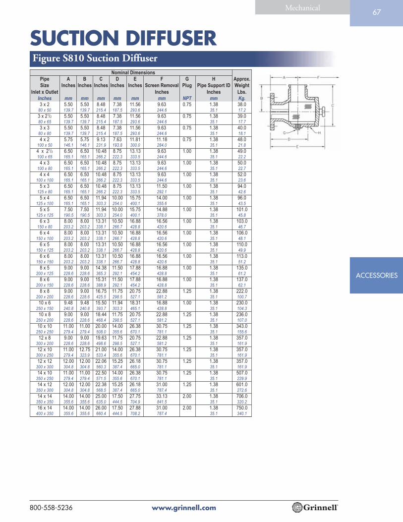
SUCTION DIFFUSER
www.grinnell.com800-558-5236
ACCESSORIES
Mechanical67
Figure S810 Suction DiffuserNominal Dimensions
Pipe A B C D E F G H Approx.
Size Inches Inches Inches Inches Inches Screen Removal Plug Pipe Support ID Weight
Inlet x Outlet Inches Inches Lbs.
Inches mm mm mm mm mm mm NPT mm Kg.3 x 2 5.50 5.50 8.48 7.38 11.56 9.63 0.75 1.38 38.0
80 x 50 139.7 139.7 215.4 187.5 293.6 244.6 35.1 17.2
3 x 21/2 5.50 5.50 8.48 7.38 11.56 9.63 0.75 1.38 39.080 x 65 139.7 139.7 215.4 187.5 293.6 244.6 35.1 17.7
3 x 3 5.50 5.50 8.48 7.38 11.56 9.63 0.75 1.38 40.080 x 80 139.7 139.7 215.4 187.5 293.6 244.6 35.1 18.1
4 x 2 5.75 5.75 9.13 7.63 11.81 11.18 0.75 1.38 48.0100 x 50 146.1 146.1 231.9 193.8 300.0 284.0 35.1 21.8
4 x 21/2 6.50 6.50 10.48 8.75 13.13 9.63 1.00 1.38 49.0100 x 65 165.1 165.1 266.2 222.3 333.5 244.6 35.1 22.2
4 x 3 6.50 6.50 10.48 8.75 13.13 9.63 1.00 1.38 50.0100 x 80 165.1 165.1 266.2 222.3 333.5 244.6 35.1 22.7
4 x 4 6.50 6.50 10.48 8.75 13.13 9.63 1.00 1.38 52.0100 x 100 165.1 165.1 266.2 222.3 333.5 244.6 35.1 23.6
5 x 3 6.50 6.50 10.48 8.75 13.13 11.50 1.00 1.38 94.0125 x 80 165.1 165.1 266.2 222.3 333.5 292.1 35.1 42.6
5 x 4 6.50 6.50 11.94 10.00 15.75 14.00 1.00 1.38 96.0125 x 100 165.1 165.1 303.3 254.0 400.1 355.6 35.1 43.5
5 x 5 7.50 7.50 11.94 10.00 15.75 14.88 1.00 1.38 101.0125 x 125 190.5 190.5 303.3 254.0 400.1 378.0 35.1 45.8
6 x 3 8.00 8.00 13.31 10.50 16.88 16.56 1.00 1.38 103.0150 x 80 203.2 203.2 338.1 266.7 428.8 420.6 35.1 46.7
6 x 4 8.00 8.00 13.31 10.50 16.88 16.56 1.00 1.38 106.0150 x 100 203.2 203.2 338.1 266.7 428.8 420.6 35.1 48.1
6 x 5 8.00 8.00 13.31 10.50 16.88 16.56 1.00 1.38 110.0150 x 125 203.2 203.2 338.1 266.7 428.8 420.6 35.1 49.9
6 x 6 8.00 8.00 13.31 10.50 16.88 16.56 1.00 1.38 113.0150 x 150 203.2 203.2 338.1 266.7 428.8 420.6 35.1 51.2
8 x 5 9.00 9.00 14.38 11.50 17.88 16.88 1.00 1.38 135.0200 x 125 228.6 228.6 365.3 292.1 454.2 428.8 35.1 61.2
8 x 6 9.00 9.00 15.31 11.50 17.88 16.88 1.00 1.38 137.0200 x 150 228.6 228.6 388.9 292.1 454.2 428.8 35.1 62.1
8 x 8 9.00 9.00 16.75 11.75 20.75 22.88 1.25 1.38 222.0200 x 200 228.6 228.6 425.5 298.5 527.1 581.2 35.1 100.7
10 x 6 9.48 9.48 15.50 11.94 18.31 16.88 1.00 1.38 230.0250 x 150 240.8 240.8 393.7 303.3 465.1 428.8 35.1 104.3
10 x 8 9.00 9.00 18.44 11.75 20.75 22.88 1.25 1.38 236.0250 x 200 228.6 228.6 468.4 298.5 527.1 581.2 35.1 107.0
10 x 10 11.00 11.00 20.00 14.00 26.38 30.75 1.25 1.38 343.0250 x 250 279.4 279.4 508.0 355.6 670.1 781.1 35.1 155.6
12 x 8 9.00 9.00 19.63 11.75 20.75 22.88 1.25 1.38 357.0300 x 200 228.6 228.6 498.6 298.5 527.1 581.2 35.1 161.9
12 x 10 11.00 12.75 21.00 14.00 26.38 30.75 1.25 1.38 357.0300 x 250 279.4 323.9 533.4 355.6 670.1 781.1 35.1 161.9
12 x 12 12.00 12.00 22.06 15.25 26.18 30.75 1.25 1.38 357.0300 x 300 304.8 304.8 560.3 387.4 665.0 781.1 35.1 161.9
14 x 10 11.00 11.00 22.50 14.00 26.38 30.75 1.25 1.38 507.0350 x 250 279.4 279.4 571.5 355.6 670.1 781.1 35.1 229.9
14 x 12 12.00 12.00 22.38 15.25 26.18 31.00 1.25 1.38 601.0350 x 300 304.8 304.8 568.5 387.4 665.0 787.4 35.1 272.6
14 x 14 14.00 14.00 25.00 17.50 27.75 33.13 2.00 1.38 706.0350 x 350 355.6 355.6 635.0 444.5 704.9 841.5 35.1 320.2
16 x 14 14.00 14.00 26.00 17.50 27.88 31.00 2.00 1.38 750.0400 x 350 355.6 355.6 660.4 444.5 708.2 787.4 35.1 340.1

BALANCING VALVES
www.grinnell.com 800-558-5236
ACCESSORIES
Mechanical68
Each Grinnell® Model CB800 Balancing Valve, as manufactured by Mepco, offers the specifier, installer andowner the features necessary to achieve accurate and efficient balancing of hydronic heating or coolingsystems.
Direct reading of valve position
Maintenance-free due to double
O-Ring seal
Thread according to DIN
and BS 21
Stem and valve disc
made of brass (DZR*)
Patented measuring
arrangement
Bronze body (Rg5)
Pressure test points
and fill-and-drain ball valve
with O-Ring seal
* DZR = de-zincification resistant brass
Direct reading of the presetting
Maintenance-free due to
double O-Ring seal
Connection suitable for
ANSI flanges
Stem made of brass (DZR*)
valve disc made of bronze (Rg 5)
Patented measuring
arrangement
Cast iron body (GG 25)
Pressure test points
with O-Ring seal
* DZR = de-zincification resistant brass
Direct reading of the presetting
Maintenance-free due to
double O-Ring seal
Standard grooved
connections
Stem made of brass (DZR*)
valve disc made of bronze (Rg 5)
Patented measuring
arrangement
Cast iron body (GG 25)
Pressure test points
with O-Ring seal
* DZR = de-zincification resistant brass
MATERIAL SPECIFICATIONS• Sizes 1/2" (DN15) through 2" (DN50), solder or
NPT threaded connection - body is bronze
• Sizes 21/2" (DN16) through 12" (DN300), groovedor flanged connection is to #125 standards - bodyis cast iron equivalent to ASME/ANSI B16.5
• All wetted brass parts are alloyed to resistdezincification.
• Dielectric fittings are not required for installation.
VALVE SIZINGAll balancing valves are sized to perform in anormal operation range between 25% and 100% ofthe full open position, at a minimum differentialpressure between 1 to 3 ft. water.
Common features include:
• Location of handwheel and test points on thesame side for easy access
• Location of test points on one end for eveneasier access
• Easy to reorient digital/vernier handwheel• Self-sealing pressure/temperature test points use
standard insertion probes to eliminate addi-tional components
• One valve for five functions– throttling – measuring (pressure & temp.)– draining – filling – positive shutoff
• Optional hose connection with ball valve foreither test point (drain the pipe you wantregardless of whether the valve is in the supplyor return piping)
• Low minimum pressure drop (Y-pattern)• Precise throttling (globe style)
• Minimum of 70 unique handwheel positions• Install valve in the supply or return line - with
flow in direction of arrow cast in body• Install horizontally or vertically• Install with handwheel up, down or on the side• Rated for 235 psi (PN16) at 300°F (150°C)• Dezincification resistant brass and bronze
components• Built-in hidden memory stop ensures return to
balanced position after shutoff• Enclosed red handwheel lock cap prevents
handwheel movement - easily defeated forauthorized valve repositioning
• Thread and sweat connections for 1/2" - 2" sizes• 125# flanges on 21/2" - 12" sizes• Groove connections for 21/2" - 12" sizes
Tech Data: G450

BALANCING VALVES
www.grinnell.com800-558-5236
ACCESSORIES
Mechanical69
Model CB800
P
H
L
D
L
D
H
Nominal Dimensions Approx. Limits Hand-
Size Connection L H D Weight PSI / °F wheel
Inches Inches Inches Inches Lbs. PN / °C Turns
mm mm mm Kg.
21/2 Groove 117/16 27/8 73/8 18.7 235 / 300 8.065 290 73.0 188 8.5 16 / 150
3 Groove 121/4 31/2 8 27.5 235 / 300 8.080 310 88.9 203 12.5 16 / 150
4 Groove 133/4 415/16 91/2 45.1 235 / 300 8.0100 350 114 240 20.5 16 / 150
5 Groove 153/4 59/16 111/4 70.4 235 / 300 8.0125 400 141 283 32 16 / 150
6 Groove 187/8 65/8 111/4 95.7 235 / 300 8.0150 480 168 285 43.5 16 / 150
8 Groove 235/8 85/8 183/8 255.2 235 / 300 12.0200 600 219 467 116 16 / 150
10 Groove 283/4 1013/16 1815/16 376.2 235 / 300 12.0250 730 273 480 171 16 / 150
12 Groove 337/16 123/4 201/4 519.2 235 / 300 12.0300 850 324 515 136 16 / 150
Nominal Dimensions Approx. Limits Hand-
Size Connection L H D Weight PSI / °F wheel
Inches Inches Inches Inches Lbs. PN / °C Turns
mm mm mm Kg.
21/2 125# 117/16 73/8 71/4 29.7 235 / 300 8.065 Flange 290 188 185 13.5 16 / 150
3 125# 121/4 8 77/8 39.6 235 / 300 8.080 Flange 310 203 200 18.0 16 / 150
4 125# 133/4 91/8 811/16 61.6 235 / 300 8.0100 Flange 350 232 220 28 16 / 150
5 125# 153/4 107/8 97/8 89.1 235 / 300 8.0125 Flange 400 275 250 40.5 16 / 150
6 125# 187/8 107/8 111/4 113.3 235 / 300 8.0150 Flange 480 277 285 51.5 16 / 150
8 125# 235/8 183/8 133/8 284.9 235 / 300 12.0200 Flange 600 467 340 129.5 16 / 150
10 125# 283/4 1815/16 1515/16 431.2 235 / 300 12.0250 Flange 730 481 405 196.0 16 / 150
12 125# 337/16 201/4 191/16 580.8 235 / 300 12.0300 Flange 850 515 485 264 16 / 150

BALANCING VALVES
www.grinnell.com 800-558-5236
ACCESSORIES
Mechanical70
H
L
H
L
3D 2D Pump 10D 2D
Valve Installation GuideAccurate flow measurement requires that thevelocity distribution near the balancing valve staysconstant, regardless of the total flow through thepipe. Fittings, such as elbows and tees, disturb thenormal flow profile which is established throughstraight pipe. Pumps create even greater distur-bances. Failure to allow water flows around fittingsand pumps to normalize can affect measuringaccuracy by as much as 20% when the valve is in theworst, fully open, position. Minimum lengths(diameters, D) of straight pipe before and after thebalancing valve prevent these errors. Follow the flowdirection arrow on the valve body for best accuracy.Valves are designed for vertical, horizontal orinclined installation.
Flow Size Connection
GPM (l/h) Inches (DN) Swt-thrd / Flng grv
0.5 - 4.1 (100 - 1000) 1/2 (15) sweat thread
4.1 - 6.0 (1.0k - 1.5k) 3/4 (20) sweat thread
6.1 - 9.2 (1.5k - 2.3k) 1 (25) sweat thread
9.2 - 20 (2.3k - 5.0k) 11/4 (32) sweat thread
20 - 29 (5.0k - 7.2k) 11/2 (40) sweat thread
29 - 40 (7.2k - 10k) 2 (50) sweat thread
40 - 102 (10k - 25k) 21/2 (65) flanged grooved
102 - 125 (25k - 31k) 3 (80) flanged grooved
125 - 210 (31k - 50k) 4 (100) flanged grooved
210 - 300 (50k - 76k) 5 (125) flanged grooved
300 - 430 (76k - 108k) 6 (150) flanged grooved
430 - 760 (108k - 190k) 8 (200) flanged grooved
760 - 1350 (190k - 340k) 10 (250) flanged grooved
1350 - 1500 (340k - 377k) 12 (300) flanged grooved
Model CB800
Valve Sizing & Selection GuideWhen maximum flow is known but a pressure dropthrough the balancing valve is unknown, select abalancing valve for a maximum pressure drop of 2ft. water (5.7 kPa) in the full open position asshown in the table below:
Minimum Pipe Diametersfrom Fittings
Nominal Dimen. Approx. Limits Hand-
Size Connection L H Weight PSI / °F wheel
Inches Inches Inches Lbs. PN / °C Turns
mm mm Kg.1/2 Female 31/8 41/4 1.37 235 / 300 7.015 NPT 80 114 0.62 16 / 1503/4 Female 35/16 49/16 1.44 235 / 300 7.020 NPT 84 115 0.65 16 / 150
1 Female 33/8 411/16 2.20 235 / 300 7.025 NPT 97.5 119 1.00 16 / 150
11/4 Female 43/8 53/8 3.00 235 / 300 10.032 NPT 110 136 1.36 16 / 150
11/2 Female 43/4 57/16 3.86 235 / 300 10.040 NPT 120 138 1.75 16 / 150
2 Female 55/16 513/16 5.64 235 / 300 10.050 NPT 150 148 2.56 16 / 1501/2 Female 31/8 41/4 1.37 235 / 300 7.015 Sweat 80 114 0.62 16 / 1503/4 Female 35/16 49/16 1.44 235 / 300 7.020 Sweat 84 115 0.65 16 / 150
1 Female 33/8 411/16 2.20 235 / 300 7.025 Sweat 97.5 119 1.00 16 / 150
11/4 Female 43/8 53/8 3.00 235 / 300 10.032 Sweat 110 136 1.36 16 / 150
11/2 Female 43/4 57/16 3.86 235 / 300 10.040 Sweat 120 138 1.75 16 / 150
2 Female 55/16 513/16 5.64 235 / 300 10.050 Sweat 150 148 2.56 16 / 150

Copper GroovedSystem
CO
PPER GRO
OV
ED SYSTEM
6

COUPLINGS
www.grinnell.com 800-558-5236
Mechanical
COPPERGROOVED
SYSTEM
72
MATERIAL SPECIFICATIONSThe applicable material specifications for ductile iron and rubber gaskets apply:
Grinnell® Copper Grooved System is designed for joining copper tube size components 2" to 8" (54,0mm to206,4mm) type K, L, M and DWV. All couplings and fittings are rated for working pressures up to 300 psidepending on copper tubing size and type (see pressure rating chart).
The Figure 672 coupling is patented and incorporates a design that allows the coupling housings to gripalong the full 360º of circumference of the copper tube. This results in a more rigid and stronger connection.
The Figure 61 flange adapter allows a direct transition from flanged components to the grooved coppercomponents.
Ductile Iron Housing Specifications• ASTM A-536 - Standard Specification for
Ductile Iron Castings Grade 65-45-12
Gasket SpecificationsTri-Seal Grade "EN" EPDM, NSF 61 approvedcompound, has a copper color code, for cold +86°F(+30°C) and hot +180°F (+82°C) potable water.Not recommended for petroleum service.
Bolt / Nut SpecificationsCarbon steel oval neck bolts and nuts are heattreated and conform to the physical properties ofASTM A-183 with a minimum tensile strength of110,000psi (758,422 kPa). Bolts and nuts are Zincelectroplated to ASTM B633.
Coatings• Copper - Acrylic Enamel
Type "K" Type "L" Type "M" DWVNominal ASTM B-88 ASTM B-88 ASTM B-88 ASTM B-306
Size Wall Max. Max. Wall Max. Max. Wall Max. Max. Wall Max. Max.Thick. Work. End Thick. Work. End Thick. Work. End Thick. Work. End
Inches Inch. Press. Load Inch. Press. Load Inch. Press. Load Inch. Press. Loadmm mm PSI/kPa Lbs./kN mm PSI/kPa Lbs./kN mm PSI/kPa Lbs./kN mm PSI/kPa Lbs./kN
2 0.083 300 1.065 0.070 300 1.065 0.058 250 890 0.042 – –54 2,1 2065 4,74 1,8 2065 4,74 1,5 1725 3,96 1,1 – –
21/2 0.095 300 1.625 0.080 300 1.625 0.065 250 1.350 – – –67 2,4 2065 7,23 2,0 2065 7,23 1,7 1725 6,01 – – –
3 0.109 300 2.300 0.090 300 2.300 0.072 250 1.415 0.045 100 76579 2,8 2065 10,23 2,3 2065 10,23 1,8 1725 6,30 1,1 690 3,40
4 0.134 300 4.005 0.110 300 4.005 0.095 250 3.340 0.058 100 1.335105 3,4 2065 17,82 2,8 2065 17,82 2,4 1725 14,86 1,5 690 5,94
5 0.160 300 6.190 0.125 300 6.19 0.109 200 4.125 0.072 100 2.060130 4,1 2065 27,55 3,2 2065 27,55 2,8 1375 18,36 1,8 690 9,17
6 0.192 300 8.840 0.140 300 8.840 0.122 200 5.890 0.083 100 2.945156 4,9 2065 39,34 3,6 2065 39,34 3,1 1375 26,21 2,1 690 13,10
8 0.271 300 15.550 0.200 300 15.550 0.170 200 10.370 0.109 100 5.180206 6,9 2065 69,2 5,1 2065 69,20 4,3 1375 46,10 2,8 690 23,0
Performance Pressure Ratings:
- COPPER SYSTEM

COUPLINGS
www.grinnell.com800-558-5236
Mechanical
COPPERGROOVED
SYSTEM
73
Figure 672 Rigid Coupling - PatentedThe Figure 672 Rigid Coupling, size range 2" to 8" (54,0 mm to206,4 mm) is capable of pressures up to 300 psig (2065 kPa) depend-ing on copper tubing size and type. It provides a rigid joint by firmlygripping along the circumference of the copper tube grooves.
Figure 672 Rigid Couplings are a proven dependable method of joiningcopper tubing and are an economical alternative to soldering (sweating)joints and can be used on type K, L, M, DWV copper tube.
Tech Data: G510
See Tyco Fire &
Building Products
Publication TFP1800
Nominal Copper Max.* Nominal Dimensions Coupling Bolts Approx.Size Tubing Gap Size Weight
OD A B CInches Inches Inches Inches Inches Inches Qty Inches Lbs.mm mm mm mm mm mm Kg
2 2.125 0.06 3.09 4.65 1.72 2 3/8 x 21/4 2.154 54,0 1,5 78,6 118,1 43,7 0,9
21/2 2.625 0.06 3.59 5.38 1.72 2 3/8 x 21/4 2.367 66,7 1,5 91,3 136,7 43,7 1,1
3 3.125 0.06 4.12 6.25 1.72 2 1/2 x 3 2.979 79,4 1,5 104,7 158,8 43,7 1,3
4 4.125 0.09 5.33 7.75 1.86 2 1/2 x 3 3.9105 104,8 2,3 135,3 196,9 47,2 1,8
5 5.125 0.09 6.48 9.25 1.86 2 5/8 x 31/4 6.0130 130,7 2,3 164,6 235,0 47,2 2,7
6 6.125 0.09 7.25 10.25 1.86 2 5/8 x 31/4 6.7156 155,6 2,3 184,1 260,4 47,2 3,0
8 8.125 0.09 9.64 12.75 1.86 2 3/4 x 43/4 10.5206 206,4 2,3 244,8 323,9 47,2 4,8
* Maximum available gap between pipe ends. Minimum gap = 0.
Certified toNSF/ANSI 61
B
A
C

FLANGES
www.grinnell.com 800-558-5236
Mechanical
COPPERGROOVED
SYSTEM
74
4 5/8 x 3
4 5/8 x 3
4 5/8 x 3
8 5/8 x 3
8 3/4 x 31/2
8 3/4 x 31/2
Nominal Copper Nominal Dimensions Bolts** Approx
Size Tubing Size WeightOD A B C D* E* F
Inches Inches Inches Inches Inches Inches Inches Inches Qty Inches Lbs.mm mm mm mm mm mm mm mm Kg
2 2.125 6.38 4.75 0.75 2.13 3.41 7.25 4.154 54,0 162,1 120,7 19,1 54,0 86,6 184,2 1,9
21/2 2.625 7.00 5.50 0.88 2.63 3.91 7.88 5.767 66,7 178,0 140,0 22,0 67,0 99,0 200,0 2,6
3 3.125 7.50 6.00 0.94 3.13 4.53 9.88 6.779 79,4 190,5 152,4 23,9 80,0 115,1 251,0 3,0
4 4.125 9.00 7.50 0.94 4.13 5.53 9.90 8.5105 104,8 228,6 190,5 23,9 105,0 140,5 251,5 3,9
5 5.125 10.00 8.50 1.00 5.13 6.72 11.38 10.3130 130,2 254,0 215,9 25,4 130,0 170,7 289,1 4,7
6 6.125 11.00 9.50 1.00 6.13 7.78 11.88 11.5156 155,6 279,4 241,3 25,4 156,0 197,6 301,8 5,2
Figure 61 Flange Adapter (ANSI Class 125/150)The Figure 61 Flange Adapter is capable of pressures up to 300 psig(20,7 Bar) depending on copper tubing size and type. It provides a directtransition from flanged components to a grooved copper tube system.I.P.S. size flange bolt patterns conform to ANSI Class 125 and 150.
B E DF
A C
Tech Data: G515
* Dimensions D and E represent minimum and maximum sealing surfaces.
** Bolts are not supplied. Bolt lengths shown are standard; it is the responsibility of the purchaser to verify correct length for the
intended application.
Note: Phenolic Type "F" flange washer adapters are required when the Figure 61 Flange Adapter is used against surfaces such as:
- Rubber surfaces
- Adapting to AWWA cast flanges
- Rubber faced wafer valves
- Serrated flange surfaces
Figure 61 Flange Adapters are not recommended for applications that incorporate tie rods for anchoring or on a standard fitting
within 90° of each other.
See Tyco Fire &
Building Products
Publication TFP1800
Certified toNSF/ANSI 61

COPPERGROOVED
SYSTEM
FITTINGS
www.grinnell.com800-558-5236
Mechanical75
- COPPER SYSTEM
MATERIAL SPECIFICATIONS
Cast fittings in 90º, 45º elbow, tees, caps, concentric reducers, and reducing tees are cast with a copper Alloyconforming to CDA C89833. Cast fittings are stronger and more durable than wrot copper fittings and areless susceptible to damage in transit or during installation. Reducing fittings are available with Groove xGroove or Groove x Cup end configurations.
Fittings are standard radius, full flow, designed for installation with Grinnell® Copper System Figure 672Couplings or Figure 61 Flange Adapters.
Fittings are rated at the pressure rating of the Figure 672 coupling or Figure 61 Flange being used.
Cast Copper Alloy Fittings• Copper Alloy conforming to CDA C89833
Tech Data: G520
Wrot Copper Fittings• ASTM B-75 C12200; Wall thickness per ASTM B-88 Type L

FITTINGS
www.grinnell.com 800-558-5236
Mechanical
COPPERGROOVED
SYSTEM
76
Figures 610, 601, 619 & 660
Figure Figure Figure Figure610 601 619 660
Nominal Copper Nominal Approx. Nominal Approx. Nominal Approx. Nominal Approx.Size Tube C to E* Weight C to E* Weight C to E* Weight E to E* Weight
ODInches Inches Inches Lbs. Inches Lbs. Inches Lbs. Inches Lbs.mm mm mm Kg. mm Kg. mm Kg. mm Kg.
2 2.125 2.91 1.95 2.19 1.6 2.69 2.5 .92 .754 54,0 73,9 0,9 55,6 0,7 68,3 1,13 23,4 ,3
21/2 2.625 3.31 2.65 2.31 2.1 3.20 3.0 .92 1.067 66,7 84,1 1,2 58,7 1,0 81,3 1,36 23,4 ,5
3 3.125 3.81 3.65 2.59 2.8 3.52 4.05 .92 1.479 79,4 96,8 1,66 65,8 1,3 89,4 2,2 23,4 ,6
4 4.125 4.75 7.0 3.19 5.7 4.25 9.15 .92 2.4105 104,8 120,7 3,18 81,0 2,6 108,0 4,15 23,4 1,1
5 5.125 5.94 11.6 3.25 8.0 5.94 17.75 .92 4.2130 130,2 150,9 5,26 82,6 3,6 150,9 8,05 23,4 1,9
6 6.125 6.94 16.62 3.5 10.5 6.94 24.4 .92 5.9156 155,6 176,7 7,54 88,9 4,8 176,3 11,07 23,4 2,7
8 8.125 7.75 23.6 4.25 16.9 7.75 36.25 .92 10.2206 206,4 196,9 10,7 108,0 7,7 196,9 16,44 23,4 4,6
C to
E
C to EE to E
FIGURE 619
TEE
FIGURE 660
END CAP
FIGURE 601
45° ELBOWC
to E
C to E
FIGURE 610
90° ELBOW
See Tyco Fire &
Building Products
Publication TFP1800
* Dimensional information in this chart is for cast fittings.

FITTINGS
www.grinnell.com800-558-5236
Mechanical
COPPERGROOVED
SYSTEM
77
Figure 621 Reducing Tee
C to
RE
C to EFIGURE 621 REDUCING TEE
CAST
GR x GR x GR
Nominal Copper Tube Nominal Nominal Approx.Size OD C to E C to RE Weight
Inches Inches Inches Inches Lbs.mm mm mm Kg.
21/2 x 21/2 x 2 2.625 x 2.625 x 2.125 3.28 3.38 3.4767 x 67 x 54 66.7 x 66.7 x 54.0 83.3 85.9 1.57
3 x 3 x 2 3.125 x 3.125 x 2.125 3.00 3.38 3.6979 x 79 x 54 79.4 x 79.4 x 54.0 76.2 85.9 1.67
3 x 3 x 21/2 3.125 x 3.125 x 2.625 3.25 3.5 4.1379 x 79 x 67 79.4 x 79.4 x 66.7 82.6 88.9 1.87
4 x 4 x 2 4.125 x 4.125 x 2.125 3.66 4.13 6.75105 x 105 x 54 104.8 x 104.8 x 54.0 93.0 104.9 3.06
4 x 4 x 21/2 4.125 x 4.125 x 2.625 3.94 4.06 7.31105 x 105 x 67 104.8 x 104.8 x 66.7 100.1 103.1 3.32
4 x 4 x 3 4.125 x 4.125 x 3.125 4.19 4.16 7.84105 x 105 x 79 104.8 x 104.8 x 79.4 106.4 105.7 3.56
5 x 5 x 3 5.125 x 5.125 x 3.125 3.75 4.63 9.35130 x 130 x 79 130.2 x 130.2 x 79.4 95.3 117.6 4.24
5 x 5 x 4 5.125 x 5.125 x 4.125 4.25 4.56 10.95130 x 130 x 105 130.2 x 130.2 x 104.8 108.0 115.8 4.97
6 x 6 x 21/2 6.125 x 6.125 x 2.625 3.63 5.13 10.78156 x 156 x 67 155.6 x 155.6 x 66.7 92.2 130.3 4.89
6 x 6 x 3 6.125 x 6.125 x 3.125 3.69 5.19 11.05156 x 156 x 79 155.6 x 155.6 x 79.4 93.7 131.8 5.01
6 x 6 x 4 6.125 x 6.125 x 4.125 4.19 5.13 12.86156 x 156 x 105 155.6 x 155.6 x 104.8 106.4 130.3 5.83
6 x 6 x 5 6.125 x 6.125 x 5.125 4.69 5.196 14.75156 x 156 x 130 155.6 x 155.6 x 130.2 119.1 131.8 6.69
Dimensional information in this chart is for cast fittings.
Figure 618 Reducing Tee618
Groove x Groove x Cup, Wrot CopperNominal Approx.
Size C to E C to RE Cup WeightInches Inches Inches Inches Lbs.mm mm mm mm Kg.
2 x 2 x 3/4 3.25 3.68 0.75 1.154 x 54 x 20 82,5 93,5 19,1 0,5
2 x 2 x 1 3.25 3.62 0.91 1.154 x 54 x 25 82,5 91,9 23,1 0,5
2 x 2 x 11/4 3.25 3.68 0.97 1.254 x 54 x 32 82,5 93,5 24,6 0,5
2 x 2 x 11/2 3.25 3.56 1.09 1.254 x 54 x 40 82,5 90,4 27,7 0,5
21/2 x 21/2 x 3/4 3.75 3.93 0.75 1.767 x 67 x 20 95,2 99,8 19,1 0,8
21/2 x 21/2 x 1 3.75 3.87 0.91 1.767 x 67 x 25 95,2 98,3 23,1 0,8
21/2 x 21/2 x 11/4 3.75 3.93 0.97 1.867 x 67 x 32 95,2 99,8 2,4 0,8
21/2 x 21/2 x 11/2 3.75 3.81 1.09 1.8 67 x 67 x 40 95,2 96,8 27,7 0,8
3 x 3 x 3/4 4.25 4.18 0.75 2.579 x 79 x 20 108,0 106,2 19,1 1,1
3 x 3 x 1 4.25 4.12 0.91 2.579 x 79 x 25 108,0 104,6 23,1 1,1
3 x 3 x 11/4 4.25 4.18 0.97 2.679 x 79 x 32 108,0 106,2 24,6 1,2
3 x 3 x 11/2 4.25 4.06 1.09 2.779 x 79 x 40 108,0 103,1 27,7 1,2
4 x 4 x 3/4 5.00 5.18 0.75 4.6105 x 105 x 20 127,0 131,6 19,1 2,1
4 x 4 x 1 5.00 5.12 0.91 4.7105 x 105 x 25 127,0 130,0 23,1 2,1
4 x 4 x 11/4 5.00 5.18 0.97 4.8105 x 105 x 32 127,0 131,6 24,6 2,2
4 x 4 x 11/2 5.00 5.06 1.09 4.9105 x 105 x 40 127,0 128,5 27,7 2,2
FIGURE 618 REDUCING TEE
WROT COPPER
GR x GR x CUP
C to E
C to
RECU
P
Dimensional information in this chart is for wrot copper fittings.

FITTINGS
www.grinnell.com 800-558-5236
Mechanical
COPPERGROOVED
SYSTEM
78
650
Groove x GrooveNominal Approx.
Size E to E WeightInches Inches Lbs.mm mm Kg.
21/2 x 2 3.29 1.467 x 54 83,6 0,6
3 x 2 2.50 1.479 x 54 63,5 0,6
3 x 21/2 2.50 1.479 x 67 63,5 0,6
4 x 2 4.75 3.2105 x 54 120,7 1,5
4 x 21/2 3.00 2.3105 x 67 76,2 1,1
4 x 3 3.00 2.4105 x 79 76,2 1,1
5 x 3 3.88 3.8130 x 79 98,6 1,7
5 x 4 3.38 3.8130 x 10⁵ 85,9 1,7
6 x 3 4.38 5.0156 x 79 111,3 2,3
6 x 4 3.88 5.1156 x 10⁵ 98,6 2,3
6 x 5 3.38 4.9156 x 130 85,9 2,2
8 x 6 5.00 9.5206 x 156 127.0 4,3
652
Groove x Groove x CupNominal Approx.
Size E to E Cup WeightInches Inches Inches Lbs.mm mm mm Kg.2 x 1 2.70 0.91 0.5
54 x 29 68,6 23,1 0,2
2 x 11/4 3.00 0.97 0.454 x 35 76,2 24,6 0,2
2 x 11/2 2.94 1.09 0.454 x 41 74,7 27,7 0,2
21/2 x 1 2.28 0.91 0.567 x 29 57,9 23,1 0,2
21/2 x 11/4 3.52 0.97 0.667 x 35 89,4 24,6 0,3
21/2 x 11/2 3.45 1.09 0.6 67 x 41 87,6 27,7 0,3
21/2 x 2 3.30 1.34 0.667 x 54 83,8 34,0 0,3
3 x 11/2 2.59 1.09 0.779 x 41 65,8 27,7 0,3
3 x 2 4.10 1.34 1.079 x 54 104,1 34,0 0,5
4 x 2 3.41 1.34 1.4105 x 54 86,6 34,0 0,6
Figures 650 & 652 Concentric Reducer
FIGURE 650 CONCENTRIC REDUCER
CAST
GR x GR
FIGURE 652 CONCENTRIC REDUCER
WROT COPPER
GR x CUP
E to E
E to E
CUP
Dimensional information in this chart is for cast fittings.
Dimensional information in this chart is for wrot copper.

COPPERGROOVED
SYSTEM
VALVES
www.grinnell.com800-558-5236
Mechanical79
B
A
D
O.D.
C Nominal Pipe DimensionsSize O.D. A B C D Weight
Inches Inches Inches Inches Inches Inches Lbs.mm mm mm mm mm mm Kg
2 2.125 3.19 5.31 2.45 10.0 4.950 54,0 81,0 135,0 57,0 254,0 2,2
21/2 2.625 3.75 5.91 2.63 10.0 5.965 66,7 96,0 150,0 67,0 254,0 2,7
3 3.125 3.75 7.68 3.13 10.0 6.680 79,4 96,0 195,0 79,0 254,0 3,0
4 4.125 4.63 8.78 4.13 10.0 11.0100 104,8 118,0 223,0 105,0 254,0 5,0
5 5.125 5.88 9.80 5.13 10.0 17.6125 130,2 149,0 249,0 130,0 254,0 8,0
6 6.125 5.88 10.86 6.13 10.0 21.6150 155,6 149,0 276,0 156,0 254,0 9,8
Model B680 Copper System Grooved End Butterfly Valvewith Lever Handle
The Model B680 is a lever handle bronze bodybutterfly valve designed for use with grooved coppertubing (CTS), fittings and couplings. The valve israted to 300 psi (20 bar) and features a 10 positionlocking lever handle and EPDM encapsulatedductile iron disc.
MATERIAL SPECIFICATIONS
Body• Cast bronze to ASTM B584-87 Copper Alloy
UNS C90500
Disc• Ductile Iron to ASTM A536 Gr. 65-45-12
encapsulated with EPDM
Upper & Lower Shafts• Stainless Steel Type 416 of ASTM A582
Note: Bronze body and EPDM disc encapsulationcompound conforms to ANSI / NSF 61 forcold +86ºF (+30ºC) and hot +180ºF (+82ºC)potable water systems.
Notes: Pressure ratings listed are CWP (cold water pressure) or
maximum working pressure within the service temperature
range of the gasket used in the coupling.
Maximum working pressures and end loads listed are total
of internal and external pressures and loads based on roll-
grooved Type K – ASTM B-88 copper tubing.
Tech Data: G530

FITTINGS
www.grinnell.com 800-558-5236
Mechanical
COPPERGROOVED
SYSTEM
80
Figure 407GG Dielectric Waterway Transition FittingThe Figure 407GG fitting protects systemsthrough an innovative steel-to-plastic designthat establishes a dielectric waterway. Thetransition fitting separates dissimilar metals inthe electrolyte (waterway) eliminating the localgalvanic cell.
The Figure 407GG transition fitting allows theconnection between steel (IPS) size pipe andcopper tube (CTS) size.
407GG
Groove x GrooveNominal Nominal Approx.
Size Outside Diameter End to End WeightInches Steel (IPS) Copper (CTS) Inches Lbs.mm mm Kg.
2 2.375 2.125 4.00 1.354 60,3 54,0 101,6 0,6
21/2 2.875 2.625 4.00 3.367 73,0 66,7 101,6 1,5
3 3.500 3.125 4.00 4.579 88,9 79,4 101,6 2,1
4 4.500 4.125 4.00 5.8105 114,3 104,8 101,6 2,6
5 5.563 5.125 4.00 7.8130 141,3 130,2 101,6 3,5
6 6.625 6.125 4.00 10.1156 168,3 155,6 101,6 4,6
8 8.625 8.125 4.00 15.1206 219,1 206,4 101,6 6,9
Copper Roll GrooverModel 1039• 11/4" - 6" SCH 40
• 2" - 8" Copper Tube
With ratchet hand crank, roll grooves 11/4" - 6", Schedule 40 or thinwall steel pipe on the scaffold or anywhere power is unavailable.
Capacity: 11/4" - 6" SCH 40 (7mm)2" - 8" Copper Tube K, L, M and DWV
Model 1039 Mini-Mite Roll Groover service tool goes from in-placegrooving and can be chucked in a Ridgid Model 300 in seconds with nogearbox removal.
Model 1039 Mini-Mite is self contained and can be entirely operated with its own multi-function crank sothere are no other tools needed! All hex drives on Model 1039 Mini-Mite are 15/16", so one wrench fitseverything.
Mini-Mites require no modifications or parts changes to groove any pipe or tubing in their size range.
Each comes with multi-step depth gauge.

Stainless Steel
STAIN
LESS STEEL7

COUPLINGSSTAINLESS STEEL SYSTEM
www.grinnell.com 800-558-5236
STAINLESSSTEEL
Mechanical82
MATERIAL SPECIFICATIONS
Stainless Steel HousingSpecifications
• Type 316L, ASTM A-743/A-743M – StandardSpecification for Castings, Iron-Chromium,Iron-Chromium-Nickel, Corrosion resistant, forGeneral Application Grade CR-8M
• Tensile Strength, minimum psi –70,000 (Mpa-485)
• Yield Strength, minimum psi –30,000 (Mpa-205)
• Elongation in 2” minimum 30%
Bolt / Nut SpecificationsStainless Steel bolts are metric track head boltsconforming to ASTM A-193M Class 2,Type 316 Grade B8M.
Class 2 Stainless Steel nuts are heavy hex nutsconforming to ASTM A-194M, Type 316,Grade 8M.
The Grinnell® Stainless Steel System is designed for joining 2" to 12" (54,0mm to 206,4mm) stainless steelpiping, schedules 5, 10, and 40.
The Figure 472 coupling patented Universal Tongue and Groove design makes for a trouble free installationand allows the coupling housing to grip along the full 360º of circumference of the pipe. This results in amore rigid and stronger connection. Coupling housings have gripping teeth in sizes 2" to 4" (54,0mm to101,6 mm) that makes the Figure 472 perfectly suited for installations where the likelihood of rotation isgreatest.
The Grinnell Stainless Steel Couplings are made of 316L and are generally compatible with grade 304stainless steel material.
Gasket SpecificationsGrade “E” EPDM gaskets have a green colorcode identification and conform to ASTMD-2000 for service temperatures from -30ºF(-34ºC) to 230ºF (110ºC). They are recom-mended for hot water not to exceed 230ºF(110ºC) plus a variety of dilute acids, oil free airand many chemical services. They are notrecommended for petroleum services.
Grade “T” Nitrile gaskets have an orange colorcode identification and conform to ASTMD-2000 for service temperatures from -20ºF(-29ºC) to 180ºF (82ºC). They are recom-mended for petroleum products, vegetable oils,mineral oils and air with oil vapors.
Grade “O” Fluoroelastomer gaskets have a bluecolor code and conform to ASTM D-2000.They are recommended for oxidizing acids,petroleum products, hydraulic fluids, lubricants,halogenated hydrocarbons.

COUPLINGS
www.grinnell.com800-558-5236
STAINLESSSTEEL
Mechanical83
Figure 472 Stainless Steel Rigid Coupling
Nominal Pipe Max. Pressures Max. End Max.End Nominal Dimension Coupling Bolts Approx.Size OD Sch 5 Sch 10 Sch 40 Load Gap A B C Size Weight
Inches Inches psi psi psi Lbs. Inches Inches Inches Inches Qty. Lbs.mm mm Bar Bar Bar kN mm mm mm mm mm Kg11/4 1.660 200 300 600 649.7 0.06 2.76 4.37 1.81 2 1.132 42.4 14 21 41 2.89 1.5 70 111 46 M10 x 57 0.5
11/2 1.900 200 300 600 852.0 0.08 2.99 4.61 1.81 2 1.140 48.3 14 21 41 3.79 2.0 76 117 46 M10 x 57 0.5
2 2.375 200 300 600 1,328.6 0.13 3.43 5.12 1.89 2 1.550 60.3 14 21 41 5.91 3.3 87 130 48 M10 x 57 0.7
21/2 2.875 200 300 600 1,949.0 0.13 3.90 5.63 1.89 2 2.465 73.0 14 21 41 8.67 3.3 99 143 48 M10 x 57 1.1
3 3.500 200 300 600 2,886.4 0.13 4.65 6.26 1.89 2 2.680 88.9 14 21 41 12.84 3.3 118 159 48 M12 x 76 1.2
4 4.500 200 300 600 4,772.5 0.19 5.83 7.52 1.97 2 3.5100 114.3 14 21 41 21.23 4.8 148 191 50 M12 x 76 1.6
5 5.563 200 300 600 7,292.5 0.19 7.09 9.72 2.05 2 7.5125 141.3 14 21 41 32.44 4.8 180 247 52 M16 x 83 3.4
6 6.625 200 300 600 10,340.8 0.19 8.11 10.55 2.13 2 7.5150 168.3 14 21 41 46.00 4.8 206 268 54 M16 x 83 3.4
8 8.625 200 300 600 17,527.7 0.19 10.55 13.54 2.64 2 18.1200 219.1 14 21 41 77.97 4.8 268 344 67 M20 x 121 8.2
10 10.750 200 300 600 27,227.8 0.13 12.83 16.42 2.64 2 24.7250 273.0 14 21 41 121.12 3.3 326 417 67 M24 x 165 11.2
12 12.750 — — — 43,696.6 0.13 15.39 18.86 2.64 2 42.1300 323.9 — — — 194.38 3.3 391 479 67 M24 x 165 19.1
The Fig. 472 Stainless Steel heavy Duty Rigid Coupling does not provide compensation for pipe system expansion and/orcontraction associated with pipe system changes.
Maximum pressure and end load are total from all loads based on standard weight steel pipe. Pressure ratings and end loadsmay differ on pipe materials and/or wall thickness. Contact Tyco Fire and Building Products for details.
Maximum end gap and deflection is for cut grooved standard weight pipe. Values for roll grooved will be 1/2 that of cut grooved.
Please refer to general Notes on page 14.
Tech Data: G560

COUPLINGS
www.grinnell.com 800-558-5236
STAINLESSSTEEL
Mechanical84
Figure 405 Stainless Steel Flexible Coupling
Nominal Pipe Max. Pressures Max. End Max.End Deflection Nominal Dimension Coupling Bolts Approx.Size OD Sch. 5 Sch. 10 Sch. 40 Load Gap Degrees Inches/ A B C Size Weight
Inches Inches psi psi psi Lbs. Inches per Foot Inches Inches Inches Qty. Lbs.mm mm Bar Bar Bar kN mm Coupling mm/m mm mm mm mm Kg11/4 1.660 325 500 750 658.7 0.13 4…19’ 0.90 2.56 4.17 1.81 2 1.532 42.4 22 34 52 2.93 3.3 75.0 65 106 46 M10 x 57 0.7
11/2 1.900 325 500 750 849.7 0.13 3…46’ 0.79 2.76 4.45 1.81 2 1.540 48.3 22 34 52 3.78 3.3 65.8 70 113 46 M10 x 57 0.7
2 2.375 225 350 500 1,328.6 0.13 3…01’ 0.63 3.27 4.88 1.89 2 1.850 60.3 16 24 34 5.91 3.3 52.5 83 124 48 M10 x 57 0.8
21/2 2.875 225 350 500 1,946.8 0.13 2…29’ 0.52 3.70 5.51 1.89 2 2.065 73.0 16.0 24 34 8.66 3.3 43.3 94 140 48 M10 x 57 0.9
3 3.500 225 350 500 2,884.2 0.13 2…03’ 0.43 4.37 6.50 1.89 2 3.180 88.9 16 24 34 12.83 3.3 35.8 111 165 48 M12 x 76 1.4
4 4.500 200 300 325 4,768.0 0.25 3…11’ 0.67 5.71 7.76 2.05 2 4.0100 114.3 14 21 22 21.21 6.4 55.8 145 197 52 M12 x 76 1.8
5 5.563 125 200 200 7,737.6 0.25 2…35’ 0.54 6.89 9.76 2.05 2 7.1125 141.3 9 14 14 34.42 6.4 45.0 175 248 52 M16 x 83 3.2
6 6.625 125 200 200 10,336.3 0.25 2…10’ 0.45 7.95 10.67 2.05 2 7.1150 168.3 9 14 14 45.98 6.4 37.5 202 271 52 M16 x 83 3.2
8 8.625 50 75 200 17,516.4 0.25 1…40’ 0.35 10.20 13.54 2.52 2 14.6200 219.1 3 5 14 77.92 6.4 29.2 259 344 64 M20 x 121 6.6
Maximum pressure and end load are total from all loads based on standard weight steel pipe. Pressure ratings and end loads maydiffer on pipe materials and/or wall thickness. Contact Tyco Fire and Building Products for details.
Maximum available gap between pipe ends, minimum gap = 0.
Maximum end gap is for cut grooved standard weight pipe. Values for roll grooved will be 1/2 that of cut grooved.
Please refer to general Notes on page 14.
Tech Data: G565

FITTINGS
www.grinnell.com800-558-5236
STAINLESSSTEEL
Mechanical85
Figure 410 & 401 Stainless Steel Elbow
Fig. 410 Fig. 40190… Elbow 45… Elbow
Nominal Pipe Approx. Approx.Size O.D. C to E Weight C to E Weight
Inches Inches Inches Lbs. Inches Lbs.mm mm mm Kg. mm Kg.
1 1.315 3.50 — 2.50 .625 33.4 88.9 — 63.5 .3
11/4 1.660 3.88 .9 2.50 .632 42.4 98.4 .4 63.5 .3
11/2 1.900 4.25 1.3 2.50 .840 48.3 108.0 .6 63.5 .4
2 2.375 4.38 2.0 2.75 .950 60.3 111.1 .9 69.9 .4
21/2 2.875 5.75 2.8 3.0 1.065 73.0 146.1 1.3 76.2 .5
3 3.500 5.88 3.8 3.38 2.180 88.9 149.2 1.7 85.7 1.0
4 4.500 7.50 5.7 4.00 3.6100 114.3 190.5 2.6 101.6 1.6
6 6.625 10.75 14.4 5.50 8.4150 168.3 273.1 6.5 139.7 3.8
8 8.625 15.00 29.3 7.25 16.5200 219.1 381.0 13.3 184.2 7.5
10 10.750 18.00 41.8 8.50 21.0250 273.0 457.2 19.0 215.9 9.5
12 12.750 21.00 46.5 10.00 23.0300 323.9 533.4 21.1 254.0 10.4
FIGURE 41090… ELBOW
FABRICATED,LONG RADIUS
FULL FLOW FITTINGS
FIGURE 40145… ELBOW
FABRICATED,LONG RADIUS
FULL FLOW FITTINGS
CE
CE
RCE
CE
R
Nominal Pipe Approx.Size O.D. C to E Weight
Inches Inches Inches Lbs.mm mm mm Kg.11/4 1.660 2.75 1.332 42.4 69.8 0.6
11/2 1.900 2.75 1.540 48.3 69.8 0.7
2 2.375 3.25 2.150 60.3 82.5 .9
21/2 2.875 3.75 2.865 73.0 95.2 1.3
3 3.500 4.25 3.980 88.9 107.9 1.8
4 4.500 5.00 7.8100 114.3 127.0 3.2
6 6.625 6.50 15.2150 168.3 165.1 6.9
8 8.625 7.75 18.1200 219.1 196.8 8.2
10 10.750 9.00 35.6250 273.0 228.6 16.2
12 12.750 10.00 51.4300 323.9 254.0 23.4
Figure 419 Tee
FIGURE 419 TEESEGMENT WELDED, FULL FLOW
CE CE
CE
Figure 460 End Cap
Nominal Pipe Approx.Size O.D. E to E Weight
Inches Inches Inches Lbs.mm mm mm Kg.
1 1.315 1.63 0.2325 33.4 41.3 0.1
11/4 1.660 1.63 0.332 42.4 41.3 0.1
11/2 1.900 1.63 0.440 48.3 41.3 0.2
2 2.375 1.63 0.550 60.3 41.3 0.2
21/2 2.875 1.75 0.765 73.0 44.5 0.3
3 3.500 1.75 1.080 88.9 44.5 0.4
4 4.500 1.75 1.6100 114.3 44.5 0.7
6 6.625 1.88 3.7150 168.3 47.6 1.7
8 8.625 4.00 8.0200 219.1 101.6 3.6
10 10.750 4.00 11.5250 273.0 101.6 5.2
12 12.750 4.00 15.1300 323.9 101.6 6.8
FIGURE 460END CAP
E E
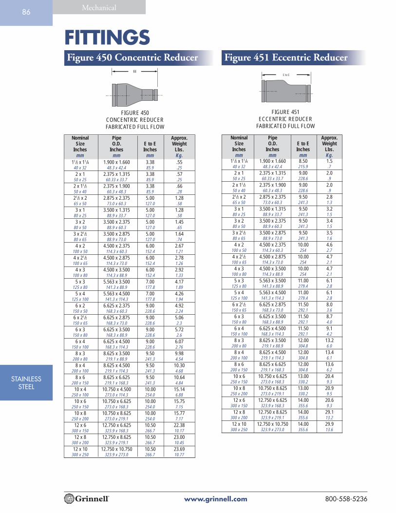
FITTINGS
www.grinnell.com 800-558-5236
STAINLESSSTEEL
Mechanical86
Figure 450 Concentric Reducer Figure 451 Eccentric Reducer
Nominal Pipe Approx.Size O.D. E to E Weight
Inches Inches Inches Lbs.mm mm mm Kg.
11/2 x 11/4 1.900 x 1.660 3.38 .5540 x 32 48.3 x 42.4 85.9 .25
2 x 1 2.375 x 1.315 3.38 .5750 x 25 60.33 x 33.7 85.9 .25
2 x 11/2 2.375 x 1.900 3.38 .6650 x 40 60.3 x 48.3 85.9 .28
21/2 x 2 2.875 x 2.375 5.00 1.2865 x 50 73.0 x 60.3 127.0 .58
3 x 1 3.500 x 1.315 5.00 1.2880 x 25 88.9 x 33.7 127.0 .58
3 x 2 3.500 x 2.375 5.00 1.4580 x 50 88.9 x 60.3 127.0 .65
3 x 21/2 3.500 x 2.875 5.00 1.6480 x 65 88.9 x 73.0 127.0 .74
4 x 2 4.500 x 2.375 6.00 2.67100 x 50 114.3 x 60.3 152.4 1.21
4 x 21/2 4.500 x 2.875 6.00 2.78100 x 65 114.3 x 73.0 152.4 1.26
4 x 3 4.500 x 3.500 6.00 2.92100 x 80 114.3 x 88.9 152.4 1.33
5 x 3 5.563 x 3.500 7.00 4.17125 x 80 141.3 x 88.9 177.8 1.89
5 x 4 5.563 x 4.500 7.00 4.26125 x 100 141.3 x 114.3 177.8 1.94
6 x 2 6.625 x 2.375 9.00 4.92150 x 50 168.3 x 60.3 228.6 2.24
6 x 21/2 6.625 x 2.875 9.00 5.06150 x 65 168.3 x 73.0 228.6 2.3
6 x 3 6.625 x 3.500 9.00 5.72150 x 80 168.3 x 88.9 228.6 2.6
6 x 4 6.625 x 4.500 9.00 6.07150 x 100 168.3 x 114.3 228.6 2.76
8 x 3 8.625 x 3.500 9.50 9.98200 x 80 219.1 x 88.9 241.3 4.54
8 x 4 8.625 x 4.500 9.50 10.30200 x 100 219.1 x 114.3 241.3 4.68
8 x 6 8.625 x 6.625 9.50 10.64200 x 150 219.1 x 168.3 241.3 4.84
10 x 4 10.750 x 4.500 10.00 15.14250 x 100 273.0 x 114.3 254.0 6.88
10 x 6 10.750 x 6.625 10.00 15.75250 x 150 273.0 x 168.3 254.0 7.15
10 x 8 10.750 x 8.625 10.00 15.77250 x 200 273.0 x 219.1 254.0 7.17
12 x 6 12.750 x 6.625 10.50 22.38300 x 150 323.9 x 168.3 266.7 10.17
12 x 8 12.750 x 8.625 10.50 23.00300 x 200 323.9 x 219.1 266.7 10.45
12 x 10 12.750 x 10.750 10.50 23.69300 x 250 323.9 x 273.0 266.7 10.77
Nominal Pipe Approx.Size O.D. E to E Weight
Inches Inches Inches Lbs.mm mm mm Kg.
11/2 x 11/4 1.900 x 1.660 8.50 1.540 x 32 48.3 x 42.4 215.9 .7
2 x 1 2.375 x 1.315 9.00 2.050 x 25 60.33 x 33.7 228.6 .9
2 x 11/2 2.375 x 1.900 9.00 2.050 x 40 60.3 x 48.3 228.6 .9
21/2 x 2 2.875 x 2.375 9.50 2.865 x 50 73.0 x 60.3 241.3 1.3
3 x 1 3.500 x 1.315 9.50 3.280 x 25 88.9 x 33.7 241.3 1.5
3 x 2 3.500 x 2.375 9.50 3.480 x 50 88.9 x 60.3 241.3 1.5
3 x 21/2 3.500 x 2.875 9.50 3.580 x 65 88.9 x 73.0 241.3 1.6
4 x 2 4.500 x 2.375 10.00 4.6100 x 50 114.3 x 60.3 254 2.7
4 x 21/2 4.500 x 2.875 10.00 4.7100 x 65 114.3 x 73.0 254 2.1
4 x 3 4.500 x 3.500 10.00 4.7100 x 80 114.3 x 88.9 254 2.1
5 x 3 5.563 x 3.500 11.00 6.1125 x 80 141.3 x 88.9 279.4 2.8
5 x 4 5.563 x 4.500 11.00 6.1125 x 100 141.3 x 114.3 279.4 2.8
6 x 21/2 6.625 x 2.875 11.50 8.0150 x 65 168.3 x 73.0 292.1 3.6
6 x 3 6.625 x 3.500 11.50 8.7150 x 80 168.3 x 88.9 292.1 4.0
6 x 4 6.625 x 4.500 11.50 9.1150 x 100 168.3 x 114.3 292.1 4.2
8 x 3 8.625 x 3.500 12.00 13.2200 x 80 219.1 x 88.9 304.8 6.0
8 x 4 8.625 x 4.500 12.00 13.4200 x 100 219.1 x 114.3 304.8 6.1
8 x 6 8.625 x 6.625 12.00 13.6200 x 150 219.1 x 168.3 304.8 6.2
10 x 6 10.750 x 6.625 13.00 20.4250 x 150 273.0 x 168.3 330.2 9.3
10 x 8 10.750 x 8.625 13.00 20.9250 x 200 273.0 x 219.1 330.2 9.5
12 x 6 12.750 x 6.625 14.00 20.6300 x 150 323.9 x 168.3 355.6 9.3
12 x 8 12.750 x 8.625 14.00 29.1300 x 200 323.9 x 219.1 355.6 13.2
12 x 10 12.750 x 10.750 14.00 29.9300 x 250 323.9 x 273.0 355.6 13.6
FIGURE 450CONCENTRIC REDUCERFABRICATED FULL FLOW
FIGURE 451ECCENTRIC REDUCER
FABRICATED FULL FLOW
E to EEE

FITTINGS
www.grinnell.com800-558-5236
STAINLESSSTEEL
Mechanical87
Figure 421 Stainless Steel Reducing TeeNominal Pipe Approx.
Size O.D. C to E WeightInches Inches Inches Lbs.
mm mm mm Kg.11/2 x 11/2 x 3/4 1.900 x 1.900 x 1.050 2.75 1.3
40 x 40 x 20 48.3 x 48.3 x 26.7 69.9 0.6
11/2 x 11/2 x 1 1.900 x 1.900 x 1.315 2.75 1.340 x 40 x 25 48.3 x 48.3 x 33.4 69.9 0.6
11/2 x 11/2 x 11/4 1.900 x 1.900 x 1.660 2.75 1.340 x 40 x 32 48.3 x 48.3 x 42.4 69.9 0.6
2 x 2 x 3/4 2.375 x 2.375 x 1.050 3.25 1.850 x 50 x 20 60.3 x 60.3 x 26.7 82.6 0.8
2 x 2 x 1 2.375 x 2.375 x 1.315 3.25 1.850 x 50 x 25 60.3 x 60.3 x 33.4 82.6 0.8
2 x 2 x 11/4 2.375 x 2.375 x 1.660 3.25 1.850 x 50 x 32 60.3 x 60.3 x 42.4 82.6 0.8
2 x 2 x 11/2 2.375 x 2.375 x 1.900 3.25 1.950 x 50 x 40 60.3 x 60.3 x 48.3 82.6 0.9
21/2 x 21/2 x 1 2.875 x 2.875 x 1.660 3.75 2.365 x 65 x 25 73.0 x 73.0 x 42.4 95.3 1.0
21/2 x 21/2 x 11/2 2.875 x 2.875 x 1.900 3.75 2.465 x 65 x 40 73.0 x 73.0 x 48.3 95.3 1.1
21/2 x 21/2 x 2 2.875 x 2.875 x 2.375 3.75 2.465 x 65 x 50 73.0 x 73.0 x 60.3 95.3 1.1
3 x 3 x 3/4 3.500 x 3.500 x 1.050 4.25 3.280 x 80 x 20 88.9 x 88.9 x 26.7 108.0 1.5
3 x 3 x 1 3.500 x 3.500 x 1.315 4.25 3.280 x 80 x 25 88.9 x 88.9 x 33.4 108.0 1.5
3 x 3 x 11/4 3.500 x 3.500 x 1.660 4.25 3.280 x 80 x 32 88.9 x 88.9 x 42.2 108.0 1.5
3 x 3 x 11/2 3.500 x 3.500 x 1.900 4.25 3.280 x 80 x 40 88.9 x 88.9 x 48.3 108.0 1.5
3 x 3 x 2 3.500 x 3.500 x 2.375 4.25 3.380 x 80 x 50 88.9 x 88.9 x 60.3 108.0 1.5
3 x 3 x 21/2 3.500 x 3.500 x 2.875 4.25 3.580 x 80 x 65 88.9 x 88.9 x 73.0 108.0 1.6
4 x 4 x 2 4.500 x 4.500 x 2.375 5.00 5.6100 x 100 x 50 114.3 x 114.3 x 60.3 127.0 2.5
4 x 4 x 21/2 4.500 x 4.500 x 2.875 5.00 6.2100 x 100 x 65 114.3 x 114.3 x 73.0 127.0 2.8
4 x 4 x 3 4.500 x 4.500 x 3.500 5.00 6.3100 x 100 x 80 114.3 x 114.3 x 88.9 127.0 2.9
6 x 6 x 3 6.625 x 6.625 x 3.500 6.50 12.7150 x 150 x 80 168.3 x 168.3 x 88.9 165.1 5.8
6 x 6 x 4 6.625 x 6.625 x 4.500 6.50 12.7150 x 150 x 100 168.3 x 168.3 x 114.3 165.1 5.8
8 x 8 x 4 8.625 x 8.625 x 4.500 7.75 15.7200 x 200 x 100 219.1 x 219.1 x 114.1 196.9 7.1
8 x 8 x 6 8.625 x 8.625 x 6.625 7.75 16.5200 x 200 x 150 219.1 x 219.1 x 168.3 196.9 7.5
10 x 10 x 6 10.750 x 10.750 x 6.625 9.00 24.8250 x 250 x 150 273.0 x 273.0 x 168.3 228.6 11.2
10 x 10 x 8 10.750 x 10.750 x 8.625 9.00 29.1250 x 250 x 200 273.0 x 273.0 x 219.1 228.6 13.2
12 x 12 x 8 12.750 x 12.750 x 8.625 10.00 52.6300 x 300 x 200 323.9 x 323.9 x 219.1 254.0 23.9
12 x 12 x 10 12.750 x 12.750 x 10.750 10.00 55.8300 x 300 x 250 323.9 x 323.9 x 273.0 254.0 25.3
C to E
C to E
FIGURE 421REDUCING TEE
SEGMENT WELDED

FITTINGS
www.grinnell.com 800-558-5236
STAINLESSSTEEL
Mechanical88
Figure 441 Flange AdapterGroove x Class 150 Flange
Nominal Pipe Approx.Size O.D. E to E Weight
Inches Inches Inches Lbs.mm mm mm Kg.
1 1.315 3.00 2.525 33.4 76.2 1.1
11/4 1.660 4.00 3.832 42.2 101.6 1.7
11/2 1.900 4.00 4.140 48.3 101.6 1.9
2 2.375 4.00 6.050 60.3 101.6 2.7
21/2 2.875 4.00 9.265 73.0 101.6 4.2
3 3.500 4.00 10.480 88.9 101.6 4.7
4 4.500 6.00 19.1100 114.3 152.4 8.7
5 5.563 6.00 23.0125 141.3 152.4 10.4
6 6.625 6.00 29.5150 168.3 152.4 13.4
8 8.625 6.00 43.5200 219.1 152.4 19.7
10 10.750 8.00 68.2250 273.1 203.2 30.9
12 12.750 8.00 96.1300 323.9 203.2 43.6
FIGURE 441FLANGE ADAPTER
E to E
Tech Data: G568

Gaskets
GA
SKETS8

GASKETS
www.grinnell.com 800-558-5236
GASKETS
Mechanical90
GRINNELL® GASKET TYPESPressure responsive gaskets are offered in a variety of types. Although they each serve a specific function theyall utilize the same sealing design.
The Grinnell Gasket is designed to provide a three-way sealing action.
(1) Installation of the gasket over the outside sealing surface of the pipe compresses the lip seal thusforming the initial seal.
(2) The installation of the housing segments around the gasket and into the pipe groove properlypositions the gasket. Tightening of the housing segments forms the gasket to the inside of thehousing and compresses it around the pipe-sealing surface thus increasing the gasket’s sealingagainst the pipe.
(3) The introduction of the system pressure energizes the pressure responsive seal of the gasket andfurther enhances the sealing action.
For Fire Protection Pressure Rating
and Listing / Approval information
contact Tyco Fire & Building Products.
LPCBVd S
Tech Data: G610

GASKETS
www.grinnell.com800-558-5236
GASKETS
Mechanical91
STYLESStandard
The standard style gasket, with a “C” shape configuration, is the most commonlyused. It is provided as the standard in the Figure 705, 707, & 772 GrinnellCouplings. The gasket is available in two types of material, Grade “E” EPDM andGrade “T” Nitrile.
Tri-SealThe Tri-Seal gasket is designed to close off the gap or gasket cavity. This is accom-plished by positioning the center “rib” of the gasket over the gap between thepipes. The Tri-Seal gasket has two tapered sealing edges in addition to the centerrib for additional strength and sealing.
The Tri-Seal gasket can be used with the Figure 705, 707, & 772 Grinnell Couplings. It isrecommended for use in low temperature and vacuum services (greater than 10" Hg) applica-tions. Note only a petroleum-free silicone based lubricant is recommended for low temperatureapplications. The gasket is available in Grade “E” EPDM.
Note: Rigid couplings are recommended for vacuum and low temperature applications.
Reducing CouplingThe gasket is provided with ribs used to position the larger pipe so that the sealinglip is located on the sealing surface of the pipe. This gasket is used only with theFigure 716 Grinnell Reducing Coupling and is available in Grade “E” EPDM.
Reducing couplings are not recommended for low temperature applications.
Flange AdapterThis gasket is specifically designed for use with the Figure 71 Flange Adapter. Thegasket has an optimum amount of rubber to provide a dependable seal between boththe pipe and mating surface, and to avoid overfilling of the gasket pocket, whichcauses assembly difficulties. The gasket is available in Grade “E” EPDM.
Mechanical Tee and StrapThe gasket provides a compression type seal, which is designed to conform tothe exterior curve (OD) of the pipe. This design is unique to both the Figure730 Mechanical Tee (threaded and grooved) and Figure 40-5 Strap. The gasket isavailable in Grade “E” EPDM.
Note: When used in low temperature applications, use a petroleum-freesilicone based lubricant otherwise no lubricant is required on MechanicalTee and Strap gaskets.

GASKETS
www.grinnell.com 800-558-5236
GASKETS
Mechanical92
Grinnell® Gasket Grade & RecommendationsThe Gasket Recommendation Table has beendeveloped to assure maximum service life. The tablewas developed from information supplied by thematerial manufacturers of the elastomer, technicalreference literature and testing conducted by TycoFire & Building Products.
In evaluating the gasket grade for intended serviceapplications the following consideration must bereviewed: system operating temperature, fluid orsolution concentration, and duration of service.
All gasket recommendations are based on a tempera-ture of 70°F (21°C) unless otherwise noted.
Technical and Engineering Services should beconsulted if combinations of service solutions arebeing considered.
Contact Tyco Fire & Building Products for recom-mendations for services not listed.
Gasket recommendations apply to Grinnell gasketsand valves only.
Grade Temp. Range Compound Color Code General Service Application
E -30ºF (-34ºC) to EPDM Green Hot water, dilute acids, alkalies, oil free air, and many chemical
+230ºF (+110ºC) services not involving petroleum products. Excellent oxidation
resistance. NOT FOR USE WITH HYDROCARBONS.
E Tri- Seal -30ºF (-34ºC) to EPDM Green Hot water, dilute acids, alkalies, and many chemical services
+230ºF (+110ºC) not involving petroleum products. Excellent oxidation
resistance. NOT FOR USE WITH HYDROCARBONS.
Recommended for low temperature and vacuum services.
T -20ºF (-29ºC) to Nitrile Orange Petroleum products, vegetable oils, mineral oils and air with
+180ºF (+82ºC) oils. Not Recommended for Hot Water Systems. Not
Recommended for Hot Dry Air Systems.
O +20ºF (-7ºC) to Fluoroelastomer Blue Oxidizing acids, petroleum products, hydraulic fluids,
+300ºF (+149ºC) lubricants, halogenated hydrocarbons.
L -30ºF (-34ºC) to Silicone Red Gasket Air without hydrocarbons, dry heat.
+350ºF (+177ºC)
EN & Cold and Hot Potable Water Copper NSF 61 Approved for potable water.Not recommended for
EN Tri-Seal up to +180ºF (+82ºC) petroleum service.

GASKETS
www.grinnell.com800-558-5236
GASKETS
Mechanical93
• Contact Tyco Fire & Building Products for an Engineering evaluation and recommendationwhere the gasket grade is shown in parenthesis.
• Specify gasket grade when ordering.
• For vacuum or low temperature systems, use Tri-Seal gasket. For low temperature applica-tions, use a petroleum-free silicone lubricant.
• Check gasket color code to be certain it is recommended for the service intended.
• Unless otherwise noted, all gasket listings are based upon a temperature of 70°F (21°C).
• For services not listed contact Tyco Fire & Building Products for recommendation.
• Where more than one gasket is shown, the preferred gasket grade is listed first.
WATER AND AIRService Gasket
Grade
Air, (no oil vapors) Temp. -30°F (-34°C) to +230°F (+110°C) E
Air, Oil Vapor Temp. -20°F (-29°C) to +150°F (+66°C) T
Water, Temp. to +230°F (+110°C) E
(NOT RECOMMENDED FOR STEAM SERVICE)
Water, Acid Mine E/T
Water, Chlorine E
Water, Deionized E
Water, Seawater E
Water, Waste (NO PETROLEUM PRODUCTS) E
Chemical Composition Gasket
Grade
Carbon Dioxide, Wet E/T
Carbon Monoxide E
Caustic Potash T
Chrome Alum T
Citric Acid E/T
Copper Chloride T
Copper Cyanide E/T
Copper Sulphate E/T
Cupric Fluoride E
Cupric Sulphate E/T
Dioctyl Phthalate E
Ethane E
Ethanolamine E
Ethyl Alcohol E
Ethyl Chloride E
Ethylene Chlorohydrin E
Ethylene Diamine T
Ethylene Glycol E/T
Ferric Sulphate T
Fluboric Acid E/T
Fly Ash E
Fomaldehyde E/T
Formamide E/T
Formic Acid E
Fructose E/T
Furfuryl Alcohol E
Glycerin E/T
Glycerol E/T
Glycol E/T
Heptane T
Hexaldehyde E
Hexane T
Chemical Composition Gasket
Grade
Hexylene Glycol T
Hydrochloric Acid to 36%, E
75°F (24°C) Max
Hydrofluosilicic Acid E
Isobutyl Alcohol E
Isopropyl Alcohol E
Lead Acetate T
Lithium Bromide T
Magnesium Chloride E/T
Magnesium Hydroxide E/T
Magnesium Sulphate E/T
Methyl Alcohol, Methanol E/T
Methyl Isobutyl Carbinol E
Mineral Oils T
Nickel Chloride E/T
Nickel Plating Solution E/T
125°F (52°C) Max
Nitric Acid, to 10%, E
75°F (24°C) Max
Nitrous Oxide E
Ozone E
Phosphate Ester E
Phosphoric Acid to 75%, E/T
70°F (21°C) Max
Potassium Bromide E/T
Potassium Carbonate E/T
Potassium Chloride E
Potassium Chromate T
Potassium Hydroxide T
Propylene Glycol E
Salicylic Acid E
Silver Nitrate E
Chemical Composition Gasket
Grade
Soda Ash, Sodium Carbonate E/T
Sodium Bicarbonate E/T
Sodium Bisulphate E/T
Sodium Bisulphite (black liquor) E/T
Sodium Bromide E/T
Sodium Chlorate E
Sodium Chloride E/T
Sodium Cyanide E/T
Sodium Hydroxide, to 50% E
Sodium Hypochlorite, to 20% E
Sodium Metaphosphate T
Sodium Nitrate E
Sodium Peroxide E
Sodium Phosphate T
Sodium Silicate T
Sodium Sulpfide T
Sodium Sulpfite Solution, to 20% T
Sodium Thiosulphate, “Hypo” T
Stannous Chloride, to 15% T
Stearic Acid T
Sulphur E
Sulphuric Acid, to 25%, E
150°F (66°C) Max
Toluene 30% T
Triethanolamine E/T
Trisdodium Phosphate - E
11lbs./50gal. (5Kg/189L)
Urea T
Vegetable Oil T
Vinyl Acetate E
Chemical Composition Gasket
Grade
Acetic Acid up to 10% E
Acetone E
Acetylene E/T
Alkalis E
Aluminum Chloride E/T
Aluminum Fluoride E/T
Aluminum Hydroxide E
Aluminum Nitrate E/T
Aluminum Salts T
Ammonia Gas, Cold E
Ammonia Liquid E
Ammonium Chloride E/T
Amyl Acetate E
Amyl Alcohol E
Aniline E
Arsenic Acid to 75% T
Barium Carbonate E
Barium Chloride E/T
Barium Hydroxide E/T
Benzoic Acid E
Benzyl Alcohol E
Borax Solutions E
Boric Acid E/T
Butyl Alcohol E/T
Butylene T
Calcium Bisulphate T
Calcium Chloride E/T
Calcium Hydroxide (Lime) E/T
Calcium Sulfate E/T
Calcium Sulfide E
Carbitol E/T
Carbon Dioxide, Dry E/T

GASKET LUBRICANTS
www.grinnell.com 800-558-5236
GASKETS
Mechanical94
Application La-Co Industries Dow Corning®
Lubri-Joint 7 Release Compound (Silicone)
Chilled Water • •
Heating • •
Compressed Air • •
Drainage • •
Sewage • •
Low Temp./Vacuum • •
Fire Protection • •
During installation of a Grinnell® Coupling, always lubricate the gasket. For couplings using the Tri-Sealgasket in a low temperature application, use a petroleum-free silicone based lubricant. For mechanical teesand straps when used in low temperature applications, use a petroleum-free silicone based lubricant, other-wise no lubricant is required.
Grinnell Mechanical Piping Products recommends two kinds of lubricant;
La-Co Industries Lubri-Joint
Dow Corning® 7 Release Compound (Silicone)
Check lubricant chart to be certain of the proper lubricantrecommended for the service intended. For information onhealth safety contact Tyco Fire & Building Products for MaterialSafety Data Sheets (MSDS).
Gasket Lubri-Joint Silicone
Size 1 qt. (946ml) container 5.3oz. (150g) tube
11/ 4" / 32mm 650 116
11/ 2" / 40mm 570 94
2" / 50mm 440 73
3" / 80mm 300 50
4" / 100mm 220 36
6" / 150mm 135 22
8" / 200mm 110 18
10" / 250mm 85 14
12" / 300mm 65 10
14" / 350mm 55 9
16" / 400mm 50 8
18" / 450mm 38 6
20" / 500mm 33 5
24" / 600mm 20 3
The table below will give and indiction on the approximate number of
gaskets which can be lubricated with one container of lubricant.
Available in:
• 1 quart
• 1 gallon
Silicone Gasket Lubricant available in:
• 8 lb. can
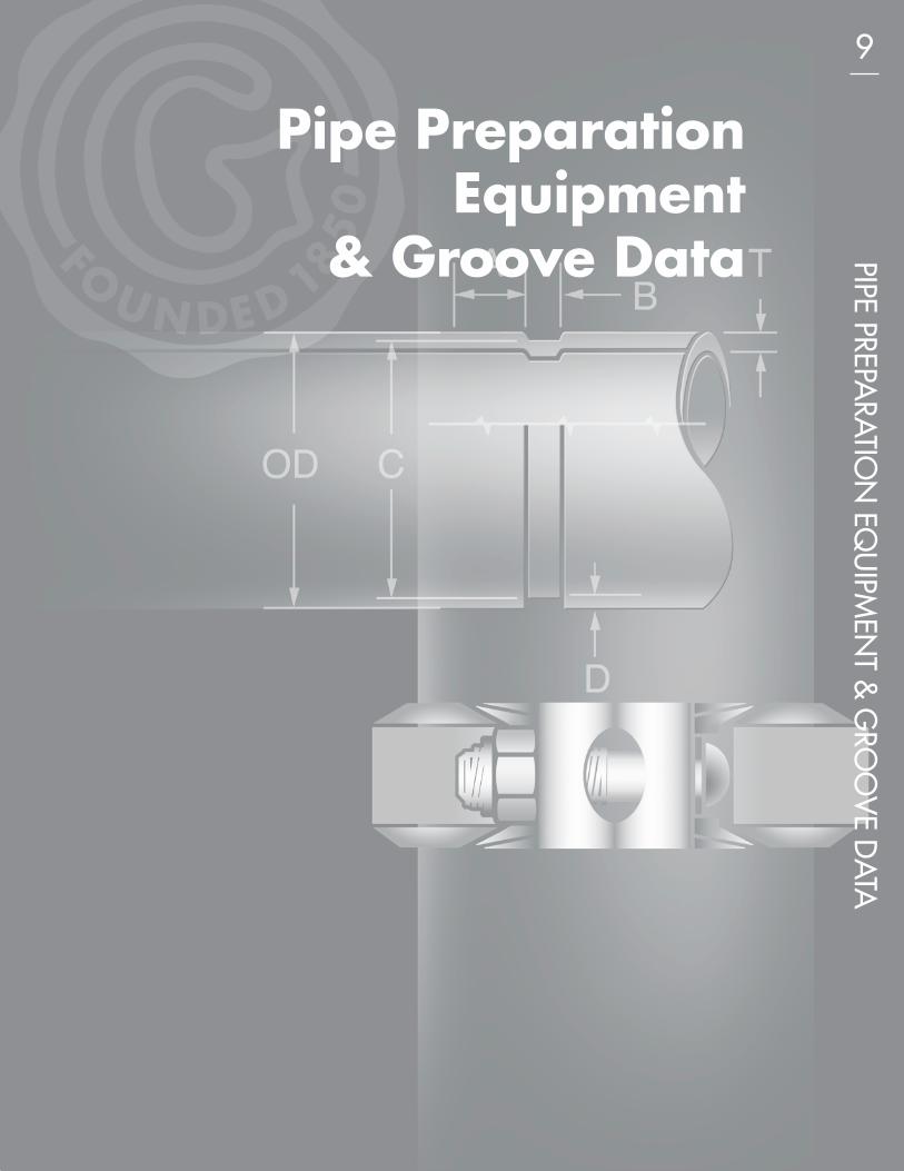
Pipe PreparationEquipment
& Groove Data PIPE PREPARATIO
N EQ
UIPM
ENT &
GRO
OV
E DA TA9

PIPE PREP. EQUIPMENT
www.grinnell.com 800-558-5236
PIPE PREP.EQUIPMENT& GROOVE
DATA
Mechanical96
Model 1112 • 1" – 12" PipePortable Roll GrooverModel 1112 requires just three Top Rollers and three Bottom Rollers toproduce specification quality grooves in pipe from 1” through 12” diameterSchedule 40. Easily portable for on-the-job work, the Model 1112’s electricmotor rotates pipe at speeds of 35 RPM. The hand hydraulic pump willdeliver up to 15,000 psi pressure at the point of roll grooving. The Model1112 is ruggedly built to deliver long, trouble-free service.
Model 1112 SpecificationsCapacity: 1" - 12" SCH 40 (10mm)
2" - 6" Copper Tubing K, L, M and DWVPipe Rotation Speed: 35 RPM
Hydraulic Pressure at Roller: 15,000 psi maxSpindle Height from Floor: 35” (889mm)Electric Motor: 11/2 HP 60Hz 110 V.1 PH.*Floor Space Required: 32” x 32” (813 x 813mm)Shipping Weight: 220 lbs. (100 kg)Interchangeable Rollers:
Top Pipe Diameter: Bottom Pipe Diameter:• 1" - 11/2" (25mm - 38mm) • 1" - 11/2" (25mm - 38mm)• 2" - 6" (51mm - 152mm) • 2" - 6" (51mm - 152mm)• 8" - 12" (203mm - 305mm) • 8" - 12" (203mm - 305mm)
*Other current characteristics available.
Standard Equipment: Electric Drive Motor • Groove Depth Gauge • HydraulicHand Pump • Top and Bottom Rollers 1 - 12” • Shipping/Storage Box • Guards •Foot Switch
Optional Equipment: Top and Bottom Copper Rollers 2 - 8”; Nipple Bracket
Portable Roll Groover

PIPE PREP. EQUIPMENT
www.grinnell.com800-558-5236
PIPE PREP.EQUIPMENT& GROOVE
DATA
Mechanical97
Model 1022 • 11/4" – 16" PipePipe Groover for Mounting on Rigid® 300 Pipe ThreaderGet double duty from the Rigid 300 Pipe Threader by converting it to a pipegroover with the Model 1022 Pipe Groover. Designed for quick, easymounting on standard Model 300, the 1022 Pipe Groover can roll groovesin pipe from 11/4" - 16" diameter. The hand hydraulic pump will deliverup to 16,000 psi pressure at the point of roll grooving. PipeThreader’s motor will rotate the pipe to produce specificationquality grooves in pipe.
Model 1022 SpecificationsCapacity: 11/4" - 12" SCH 40 (10mm)
12" - 16" Standard Wall 0.375 (9.5mm)2" - 6" Copper Tubing K, L, M and DWV
Hydraulic Pressure at Roller: 16,000 psi. max.Shipping Weight: 285 lbs. (129.3 kg)Interchangeable Rollers:
Top Pipe Diameter: Bottom Pipe Diameter:• 11/4" - 11/2" (32mm - 38mm) • 11/4" - 11/2" (32mm - 38mm)• 2" - 31/2" (51mm - 89mm) • 2" - 31/2" (51mm - 89mm)• 4" - 6" (102mm - 152mm) • 4" - 6" (102mm - 152mm)• 8" - 12" (203mm - 305mm) • 8" - 12" (203mm - 305mm)• 14" - 16" (356mm - 407mm) • 14" - 16" (356mm - 407mm)
Standard Equipment:Grooved Depth Gauge • Hydraulic Hand Pump • Rollers 11/4" - 16" • Shipping/Storage Box •Pipe Nipple and Stabilizer Bracket • Guards
Pipe Groover for Mounting on Rigid
300 Pipe Threader
Model 1012 • 1" – 12" PipePortable Roll GrooverFor Grooving 1" - 12" schedule 40, the Model 1012 is designed with a newhydraulic ratio along with an advanced spindle design which allows greaterstrength and pressure in a compact package for grooving up to 12" Schedule40, using a standard model Ridgid® 300.
A hydraulic hand pump will deliver increased pressure for groovingup to 0.406 wall pipe to specification quality grooves. Top andbottom roll change is made easy with cross taper pin in the bottomroll and socket set screw in the top roll for positive no slip design.
Model 1012 SpecificationsCapacity: 1" - 12" SCH 40 (10mm)
2" - 6" Copper Tubing K, L, M and DWVShipping Weight: 125 lbs.Interchangeable Rollers:
Top Pipe Diameter: Bottom Pipe Diameter:• 1" - 11/2" (25mm - 38mm) • 1" - 11/2" (25mm - 38mm)• 2" - 6" (51mm - 152mm) • 2" - 6" (51mm - 152mm)• 8" - 12" (203mm - 305mm) • 8" - 12" (203mm - 305mm)
Optional Equipment: Pipe Nipple and Stabilizer Bracket
Portable Roll Groover

PIPE PREP. EQUIPMENT
www.grinnell.com 800-558-5236
PIPE PREP.EQUIPMENT& GROOVE
DATA
Mechanical98
Model 1041 • 1" – 12" Pipe
Roll Grooving Attachment for use with Rigid® 300 Pipe Threader• Quickly converts your Rigid 300 Threader to a production roll groover.• Mounts/dismounts easily on standard Model 300.
Model 1041 SpecificationsCapacity: 1" - 6" SCH 40 (6mm)
1" - 12" SCH 10 (5mm)2" - 6" Copper Tubing K, L, M and DWV
Maximum Pressure at Roller: 8000 psi
Shipping Weight: 94 lbs. (42.6 kgs)
Interchangeable Rollers:Top Pipe Diameter: Bottom Pipe Diameter:
• 1" - 6" (25mm - 152mm) • 1" - 11/2" (25mm - 38mm)• 8" - 12" (203mm - 305mm) • 2" - 6" (51mm - 152mm)
• 8" - 12" (203mm - 305mm)
Roll Grooving Attachment
mounted on Rigid 300 Pipe Threader
Portable Roll Groover
Model 1010 • 11/2" - 12" PipePortable Roll GrooverProduces accurately rolled grooves in a wide range of pipe types-including newer varieties ofthin-wall pipe. Use it in the shop or at the job site. Easily operated hydraulic hand pumpdelivers up to 8000 psi of rolling force to the pipe face. Pre-set depth gauge automaticallycontrols depth of rolled groove. Pipe is rotated by means of a speed reducer drivenby the unit’s electric motor. The drive shaft and idler shaft are machined fromVacuum Melt Aircraft quality alloy steel to insure long service life. Easily inter-changeable Top and Bottom Rollers (average time: less than 3 minutes) permitsrapid change of pipe diameters with nominal set-up costs.
Shipped in a durable, reuseable hinged box.
Model 1010 SpecificationsCapacity: 11/2" - 6" SCH 40 (6mm)
11/2" - 12" SCH 10 (5mm)
Pipe Rotation Speed: 30 RPM
Hydraulic Pressure at Roller: 8,000 psi. max.
Spindle Height from Floor: 33" (838mm)
Electric Motor: 11/2 HP 60 Hz 110 V. 1 PH*
Floor Space Required: 32" x 32" (813mm x 813mm)
Shipping Weight: 300 lbs. (136 kgs)
Interchangeable Rollers:Top Pipe Diameter: Bottom Pipe Diameter:
• 11/2" - 6" (38mm - 152mm) • 11/2" (38mm) • 4" - 6" (102mm - 152mm)• 8" - 12" (203mm - 305mm) • 2" - 31/2" (51mm - 89mm) • 8" - 12" (203mm - 305mm)
*Other current characteristics available.
Standard Equipment:Electric Motor • Groove Depth Gauge • Hydraulic Pump • Shipping/Storage Box •Rolls as Specified in Price List • Guards • Foot Switch

PIPE PREP. EQUIPMENT
www.grinnell.com800-558-5236
PIPE PREP.EQUIPMENT& GROOVE
DATA
Mechanical99
Portable Roll Groover
Model 1023 • 11/4" – 24" Pipe
Portable Roll GrooverPortable Pipe Groover has been designed with a heavy-duty, high efficiency gear reducer.The helical inline gear reducer with only 5 percent energy loss, will allow grooving11/4" - 24" with a 110 volt electrical service. The hand hydraulic pump applies upto 16,000 psi at the point of roll grooving to produce accurate grooves for quickinstallation of pipe couplings. Use it at the job site or in the shop. Top and bottomrollers are easily interchanged to handle a wide range of pipe diamerters. Additionalroll sets are available for copper tube grooving and also flush seal gasket dimensions.
Model 1023 SpecificationsCapacity: 11/4" - 12" SCH 40 (10mm)
12" - 24" Standard Wall 0.375 (9.5mm)2" - 6" Copper Tubing K, L, M and DWV
Spindle Speed: 30 RPM
Hydraulic Pressure at Roller: 16,000 psi. max.
Spindle Height from Floor: 33" (838mm)
Electric Motor: 11/2 HP 60 Hz 110 V. 1 PH
Floor Space Required: 311/2" x 331/2" (800mm x 857mm)
Shipping Weight: 430 lbs.
Interchangeable Rollers:Top Pipe Diameter: Bottom Pipe Diameter:
• 11/4" - 11/2" (32mm - 38mm) • 11/4" - 11/2" (32mm - 38mm)• 2" - 31/2" (51mm - 89mm) • 2" - 31/2" (51mm - 89mm)• 4" - 6" (102mm - 152mm) • 4" - 6" (102mm - 152mm)• 8" - 12" (203mm - 305mm) • 8" - 12" (203mm - 305mm)• 14" - 16" (356mm - 407mm) • 14" - 16" (356mm - 407mm)• 18" - 24" (457mm - 610mm) • 18" - 24" (457mm - 610mm)
Standard Equipment:Electric Motor • Grooved Depth Gauge • Hydraulic Hand Pump • Shipping/StorageBox • Rolls as Specified in Price List • Guards • Foot Switch
Nipple Bracket
Model 4037 • 8" – 24" Pipe
Nipple BracketThe Model 4037 Nipple Bracket was developed to permit safer, more efficient rollgrooving of pipe too short to mount in a pipe stand. The plastic composition clamp-rollerfixes the pipe nipple in a controlled, slightly eccentric position so that the pipe is heldfirmly against the back flange of the bottom roller as it rotates. Pipe nipples as short as 6"can be grooved using this tool, permitting high production rates without the need formanual positioning by shop personnel.
Model 4037 SpecificationsCapacity: 8" - 24" PipeFits Model 1023 Roll Groovers

PIPE PREP. EQUIPMENT
www.grinnell.com 800-558-5236
PIPE PREP.EQUIPMENT& GROOVE
DATA
Mechanical100
Automated Roll Groover
Model 2021 • 11/4" – 24" Pipe
Automated Roll GrooverSix easily interchanged Top and Bottom Rollers give Model 2021 the versatility to meetvirtually any piping system requirement. The self-contained hydraulic system provides upto 16,000 psi pressure at the point of roll grooving. Hydraulic pressure is adjustable toprovide optimum grooving efficiency for all diameters and wall thicknesses within themachines’s range. Model 2021 is shipped completely assembled with Top and BottomRollers 4" - 6" installed on machine.
Model 2021 SpecificationsCapacity: 11/4" - 12" SCH 40 (10mm)
12" - 24" Standard Wall 0.375 (9.5mm)2" - 6" Copper Tubing K, L, M and DWV
Pipe Rotation Speed: 30 RPM
Hydraulic Pressure at Roller: 16,000 psi. max.
Spindle Height from Floor: 33" (838mm)
Electric Motor: 3 HP 60 Hz 220 V. 3 PH*
Hydraulic Pump Motor: 1 HP 60 Hz 220 V. 3 PH
Floor Space Required: 30" x 22" (762mm x 559mm)
Shipping Weight: 640 lbs. (290 kgs)
Interchangeable Rollers:Top Pipe Diameter: Bottom Pipe Diameter:
11/4" - 11/2" (32mm - 38mm) 11/4" - 11/2" (32mm - 38mm)2" - 31/2" (51mm - 89mm) 2" - 31/2" (51mm - 89mm)4" - 6" (102mm - 152mm) 4" - 6" (102mm - 152mm)8" - 12" (203mm - 305mm) 8" - 12" (203mm - 305mm)14" - 16" (356mm - 407mm) 14" - 16" (356mm - 407mm)18" - 24" (457mm - 610mm) 18" - 24" (457mm - 610mm)
*Other current characteristics available.
Standard Equipment:Electric Drive Motor • Limit Switch for Depth Gauging • Grooved Depth Gauge • HydraulicPump • Model 4037 Nipple Bracket • Rolls as Specified in Price List • Guards • Foot Switch

PIPE PREP. EQUIPMENT
www.grinnell.com800-558-5236
PIPE PREP.EQUIPMENT& GROOVE
DATA
Mechanical101
Porta-Bore
Model 3013 • 11/4" - 12" Pipe, up to 41/2" dia. holes
Porta-Bore• Solid alloy aluminum construction
• Slide and gibbs are heat treated aluminum that is Teflon® coated to insurelong life. Slide assembly is positioned together by gauge block machining.This assembly is located by dowelled gibbs that are precisely aligned with theV-block. There are no elongated holes which could allow missaligment.
• Motor is a 10 Amp draw industrial drill motor with internal 4-speed gearbox110, 175, 245, 385 RPM. Spindle bore is a No. 3 Morse Taper.
• Electrical panel meets the highest standard of operating safety. A cuircuitbreaker assures no safety hazard to the operator or machine.
• Arbor support design for use with Sluggger cutters, or drill chuck for usewith hole saws or drills.
• Chain clamp is standard on all units and clamps to pipediameters 11/4" - 12"*
• Optional speed toggle clamp, clamps to 11/4" - 6" pipe*.
* Both clamps ensure positive holding during hole cutting operations and can be used in any position.
• Oil Feed - the arbor is designed with an oil reservoir for automatic gravity feed during the cuttingoperation in the vertical position.
• Easy part replacement. Building block design allows easy part repair or replacement. (No need toship machine out for repair.)
Model 3013 Specifications• Heavy Duty - 42 lbs.; 110, 175, 245, 385 RPM.
• Cuts up to 41/2" diameter holes in 11/4" - 12" pipe.
• 110 volts 10 amps (220 volts available).

PIPE PREP. EQUIPMENT
www.grinnell.com 800-558-5236
PIPE PREP.EQUIPMENT& GROOVE
DATA
Mechanical102
MODEL 4000Capacity: 2" - 8" Pipe; 900 lbs. max.
The base of this stand is the same as used in Model 4031, above. A Saddle withfour roller bearings provides greater side support for the pipe and increased damp-ening of vibration without imparing the unit’s free-rolling characteristics. Saddleheight is adjustable over a 10" (254mm) range.
The four-roller-bearing saddle may be ordered alone as no. 4001. Replacementroller bearing is no. 4025
MODEL 4031Capacity: 1" - 4" Pipe; 600 lbs. max.
A 22" diameter base and 2" column give this stand plenty of strength forsupporting any pipe in its size range. The Saddle has two roller bearings forfree rotation of the pipe and absorbs vibration to ensure a smooth, uniformgroove. Saddle height is adjustable over a 10" (254mm) range.
The two-roller-bearing saddle may be ordered alone as no. 4032 . Replacementroller bearing is no. 4025
MODEL 4033Capacity: 2" - 14" Pipe; 1200 lbs. max.
This extra heavy duty pipe support stand uses two 2" columns on a 22" diameterbase to give it exceptional stability and resistance to vibration and pendulum effect.Each column incorporates a sturdy, threaded post, adjustable over a 10" (254mm)range. The saddle utilizes six roller bearings in an array that provides excellentsupport for all pipes in its size range.
Replacement roller bearing is no. 4025
Pipe Support StandsPipe support stands should always be used when rolling or cutting grooves in pipe. Forcut grooving they are essential to keep the pipe level; for roll grooving, stnds are adjustedto provide the slight downward pitch needed to keep the end of the pipe in firm contacewith the back flange of the bottom roller.

PIPE PREP. EQUIPMENT
www.grinnell.com800-558-5236
PIPE PREP.EQUIPMENT& GROOVE
DATA
Mechanical103
MODEL 103411/4" - 6" SCH 40
Same capacity as the 1039, but is used with the Rigid® Model 300 Threader forfaster easier grooving.
Capacity: 11/4" through 6" SCH 40 (7mm)
Model 103911/4" - 6" SCH 40, 2" - 8" Copper Tube
With ratchet hand crank, roll grooves 11/4" - 6", Schedule 40 or thin wall steelpipe on the scaffold or anywhere power is unavailable.
Capacity: 11/4" - 6" SCH 40 (7mm)2" - 8" Copper Tube K, L, M and DWV
Model 1039 Mini-Mite Roll Groover service tool goes from in-placegrooving and can be chucked in a Ridgid Model 300 in seconds with nogearbox removal.
Model 1039 Mini-Mite is self contained and can be entirely operated with its own multi-function crank sothere are no other tools needed! All hex drives on Model 1039 Mini-Mite are 15/16", so one wrench fitseverything.
Mini-Mites require no modifications or parts changes to groove any pipe or tubing in their size range.
Each comes with multi-step depth gauge.
MINI-MITES™
Roll Groovers for handling the unexpectedMini-Mite roll groovers allow you handle anything when you get on the job site. They’re handy, portable job-site tools that can save you hours of waiting for pipe to come back from the shop. New design has rollerbearing front and back on main shaft.
MODEL 10662" - 8" Copper Tube
Is also used with the Model 300, but is designed to groove2" - 8" copper tube.
Capacity: 2" - 8" Copper Tube K, L, M and DWV

GROOVE DATA
www.grinnell.com 800-558-5236
PIPE PREP.EQUIPMENT& GROOVE
DATA
Mechanical104
Nominal Pipe O.D. A B C D T Maximum
Pipe Inches ±0.030" ±0.030" Groove Diameter Groove Depth Minimum Allow Flare
Size mm ±0.76mm ±0.76mm Inches (ref. only) Wall Diameter
Inches O.D. Tolerance Inches Inches mm Inches Inches Inches
mm + - mm mm Actual Tol.+0.000 mm mm mm
11/4 1.660 0.016 0.016 0.625 0.281 1.535 -0.015 0.062 0.065 1.7732 42.4 0.41 0.41 15.88 7.14 38.99 -0.38 1.60 1.65 44.96
11/2 1.900 0.019 0.019 0.625 0.281 1.775 -0.015 0.062 0.065 2.0140 48.3 0.48 0.48 15.88 7.14 45.09 -0.38 1.60 1.65 51.05
2 2.375 0.024 0.024 0.625 0.344 2.250 -0.015 0.062 0.065 2.4850 60.3 0.61 0.61 15.88 8.74 57.15 -0.38 1.60 1.65 62.99
21/2 2.875 0.029 0.029 0.625 0.344 2.720 -0.018 0.078 0.083 2.9865 73.0 0.74 0.74 15.88 8.74 69.09 -0.46 1.98 2.11 75.69
76.1mm 3.000 0.030 0.030 0.625 0.344 2.845 -0.018 0.076 0.083 3.1076.1 0.76 0.76 15.88 8.74 72.26 -0.46 1.93 2.11 78.74
3 3.500 0.035 0.031 0.625 0.344 3.344 -0.018 0.078 0.083 3.6080 88.9 0.89 0.79 15.88 8.74 84.94 -0.46 1.98 2.11 91.44
108.0mm 4.250 0.043 0.031 0.625 0.344 4.084 -0.020 0.083 0.083 4.35108.0 1.09 0.79 15.88 8.74 103.73 -0.51 2.11 2.11 110.49
4 4.500 0.045 0.031 0.625 0.344 4.334 -0.020 0.083 0.083 4.60100 114.3 1.14 0.79 15.88 8.74 110.08 -0.51 2.11 2.11 116.84
133.0mm 5.250 0.053 0.031 0.625 0.344 5.084 -0.022 0.083 0.109 5.35133.4 1.35 0.79 15.88 8.74 129.13 -0.56 2.11 2.77 135.89
139.7mm 5.500 0.056 0.031 0.625 0.344 5.334 -0.022 0.083 0.109 5.60139.7 1.42 0.79 15.88 8.74 135.48 -0.56 2.11 2.77 142.24
5 5.563 0.056 0.031 0.625 0.344 5.395 -0.022 0.084 0.109 5.66125 141.3 1.42 0.79 15.88 8.74 137.03 -0.56 2.13 2.77 143.76
159.0mm 6.250 0.063 0.031 0.625 0.344 6.084 -0.030 0.083 0.109 6.35159.0 1.60 0.79 15.88 8.74 154.53 -0.76 2.11 2.77 161.29
165.1mm 6.500 0.063 0.031 0.625 0.344 6.330 -0.022 0.085 0.109 6.60165.1 1.60 0.79 15.88 8.74 160.78 -0.56 2.16 2.77 167.64
6 6.625 0.063 0.031 0.625 0.344 6.455 -0.022 0.085 0.109 6.73150 168.3 1.60 0.79 15.88 8.74 163.96 -0.56 2.16 2.77 170.94
216.3mm 8.516 0.063 0.031 0.750 0.469 8.331 -0.025 0.092 0.109 8.69216.3 1.60 0.79 19.05 11.91 211.61 -0.64 2.34 2.77 220.73
8 8.625 0.063 0.031 0.750 0.469 8.441 -0.025 0.092 0.109 8.80200 219.1 1.60 0.79 19.05 11.91 214.40 -0.64 2.34 2.77 223.52
10 10.750 0.063 0.031 0.750 0.469 10.562 -0.027 0.094 0.134 10.92250 273.0 1.60 0.79 19.05 11.91 268.27 -0.69 2.39 3.40 277.37
12 12.750 0.063 0.031 0.750 0.469 12.531 -0.030 0.109 0.156 12.92300 323.9 1.60 0.79 19.05 11.91 318.19 -0.76 2.77 3.96 328.17
14 14.000 0.063 0.031 0.938 0.469 13.781 -0.30 0.109 0.156 14.10350 355.6 1.60 0.79 23.83 11.91 350.04 -0.76 2.77 3.96 358.14
16 16.000 0.063 0.031 0.938 0.469 157.81 -0.30 0.109 0.165 16.10400 406.4 1.60 0.79 23.83 11.91 400.84 -0.76 2.77 4.19 408.94
18 18.000 0.063 0.031 1.000 0.469 17.781 -0.30 0.109 0.165 18.16450 457.2 1.60 0.79 25.40 11.91 451.64 -0.76 2.77 4.19 461.26
20 20.000 0.063 0.031 1.000 0.469 19.781 -0.30 0.109 0.188 20.16500 508.0 1.60 0.79 25.40 11.91 502.44 -0.76 2.77 4.78 512.06
24 24.000 0.063 0.031 1.000 0.500 23.656 -0.30 0.172 0.218 24.20600 609.6 1.60 0.79 25.40 12.70 600.86 -0.76 4.37 5.54 614.68
TB
D
COD
A
Please refer to General Notes on page 14.
Roll Groove Standard Specification forSteel & Other IPS Pipe
1 – The maximum allowable tolerances for IPS Pipefrom square cut ends is: 0.030" (0.76mm) forsizes 11/4" thru 3"; 0.045" (1.14mm) for sizes 4"thru 6"; and 0.060" (1.52mm) for sizes 8" andabove.
2 – Gasket Seating Surface “A” must be free fromscore marks, ridges, indentations, projections,loose paint, scale, dirt chips, grease, rust, etc.that would prevent a positive seal.
3 – Groove Diameter “C” must be uniform deptharound the circumference of the pipe.
4 – Groove Depth “D” is a reference dimensiononly. The Groove Diameter “C” must bemaintained.
5 – Minimum Wall Thickness “T” is the minimumwall thickness that should be roll grooved.
6 – Maximum allowable pipe end flare diameter ismeasured at the pipe end diameter.
Tech Data: G710

GROOVE DATA
www.grinnell.com800-558-5236
PIPE PREP.EQUIPMENT& GROOVE
DATA
Mechanical105
Nominal Pipe O.D. A B C D T
Pipe Inches ±0.030" ±0.030" Groove Diameter Groove Depth Minimum
Size mm ±0.76mm ±0.76mm Inches (ref. only) Wall
Inches O.D. Tolerance Inches Inches mm Inches Inches
mm + - mm mm Actual Tol.+0.000 mm mm
11/4 1.660 0.016 0.016 0.625 0.313 1.535 -0.015 0.062 0.06232 42.4 0.41 0.41 15.88 7.95 38.99 -0.38 1.60 1.60
11/2 1.900 0.019 0.019 0.625 0.313 1.775 -0.015 0.062 0.06240 48.3 0.48 0.48 15.88 7.95 45.09 -0.38 1.60 1.60
2 2.375 0.024 0.024 0.625 0.313 2.250 -0.015 0.062 0.06250 60.3 0.61 0.61 15.88 7.95 57.15 -0.38 1.60 1.60
21/2 2.875 0.029 0.029 0.625 0.313 2.720 -0.018 0.078 0.07865 73.0 0.74 0.74 15.88 7.95 69.09 -0.46 1.98 1.98
76.1mm 3.000 0.030 0.030 0.625 0.313 2.845 -0.018 0.076 0.07676.1 0.76 0.76 15.88 7.95 72.26 -0.46 1.93 1.93
3 3.500 0.035 0.031 0.625 0.313 3.344 -0.018 0.078 0.07880 88.9 0.89 0.79 15.88 7.95 84.94 -0.46 1.98 1.98
108.0mm 4.250 0.042 0.031 0.625 0.375 4.084 -0.020 0.083 0.083108.0 1.07 0.79 15.88 9.53 103.73 -0.51 2.11 2.11
4 4.500 0.045 0.031 0.625 0.375 4.334 -0.020 0.083 0.083100 114.3 1.14 0.79 15.88 9.53 110.08 -0.51 2.11 2.11
133.0mm 5.250 0.052 0.031 0.625 0.375 5.084 -0.020 0.083 0.083133.4 1.32 0.79 15.88 9.53 129.13 -0.51 2.11 2.11
139.7mm 5.500 0.056 0.031 0.625 0.375 5.334 -0.020 0.083 0.083139.7 1.42 0.79 15.88 9.53 135.48 -0.51 2.11 2.11
5 5.563 0.056 0.031 0.625 0.375 5.395 -0.022 0.084 0.084125 141.3 1.42 0.79 15.88 9.53 137.03 -0.56 2.13 2.13
159.0mm 6.250 0.063 0.031 0.625 0.375 6.084 -0.022 0.083 0.083159.0 1.60 0.79 15.88 9.53 154.53 -0.56 2.11 2.11
165.1mm 6.500 0.063 0.031 0.625 0.375 6.330 -0.022 0.085 0.085165.1 1.60 0.79 15.88 9.53 160.78 -0.56 2.16 2.16
6 6.625 0.063 0.031 0.625 0.375 6.455 -0.022 0.085 0.085150 168.3 1.60 0.79 15.88 9.53 163.96 -0.56 2.16 2.16
216.3mm 8.516 0.063 0.031 0.750 0.438 8.331 -0.025 0.092 0.092216.3 1.60 0.79 19.05 11.13 211.61 -0.64 2.34 2.34
8 8.625 0.063 0.031 0.750 0.438 8.441 -0.025 0.092 0.092200 219.1 1.60 0.79 19.05 11.13 214.40 -0.64 2.34 2.34
10 10.750 0.063 0.031 0.750 0.500 10.562 -0.027 0.094 0.094250 273.0 1.60 0.79 19.05 12.70 268.27 -0.69 2.39 2.39
12 12.750 0.063 0.031 0.750 0.500 12.531 -0.030 0.109 0.109300 323.9 1.60 0.79 19.05 12.70 318.19 -0.76 2.77 2.77
14 14.000 0.063 0.031 0.938 0.500 13.781 -0.30 0.109 0.281350 355.6 1.60 0.79 23.83 12.70 350.04 -0.76 2.77 7.14
16 16.000 0.063 0.031 0.938 0.500 157.81 -0.30 0.109 0.312400 406.4 1.60 0.79 23.83 12.70 400.84 -0.76 2.77 7.92
18 18.000 0.063 0.031 1.000 0.500 17.781 -0.30 0.109 0.312450 457.2 1.60 0.79 25.40 12.70 451.64 -0.76 2.77 7.92
20 20.000 0.063 0.031 1.000 0.500 19.781 -0.30 0.109 0.312500 508.0 1.60 0.79 25.40 12.70 502.44 -0.76 2.77 7.92
24 24.000 0.063 0.031 1.000 0.562 23.656 -0.30 0.172 0.375600 609.6 1.60 0.79 25.40 14.27 600.86 -0.76 4.37 9.53
Cut Groove Standard Specification forSteel & Other IPS Pipe
TB
D
COD
A
1 – The maximum allowable tolerances for IPS Pipefrom square cut ends is: 0.030" (0.76mm) forsizes 11/4" thru 3"; 0.045" (1.14mm) for sizes 4"thru 6"; and 0.060" (1.52mm) for sizes 8" andabove.
2 – Gasket Seating Surface “A” must be free fromscore marks, ridges, indentations, projections,loose paint, scale, dirt chips, grease, rust, etc.that would prevent a positive seal.
3 – Groove Diameter “C” must be uniformdepth around the circumference of thepipe.
4 – Groove Depth “D” is a reference dimen-sion only. The Groove Diameter “C”must be maintained.
5 – Minimum Wall Thickness “T” is theminimum wall thickness that should becut grooved.
Please refer to General Notes on page 14.
Tech Data: G710

GROOVE DATA
www.grinnell.com 800-558-5236
PIPE PREP.EQUIPMENT& GROOVE
DATA
Mechanical106
Roll Groove Standard Specification for Copper Tubing
1 – Nominal Tubing, ASTM B-88 drawn coppertubing size.
2 – Outside Diameter "OD", of roll grooved tubingshall not vary more than the tolerance listed.The maximum tolerance from square cut endsis: 0.030" (0.76mm) for sizes 2" – 3" (54.0 –79.4mm); 0.045" (1.14mm) for sizes 4" – 6"(104.8 – 155.6mm); measured from true squareline.
3 – Gasket Seating Surface "A", must be free fromroll marks, indentations, projections, loose scale,dirt, chips, grease, etc. that would prevent apositive seal.
4 – Groove Width Bottom, to be free of loose dirt,chips and scale that may interfere with propercoupling assembly.
5 – The Groove Diameter "C", must beuniform in depth for the entire circum-ference of the tubing. Groove must bemaintained within the tolerance listed.
6 – Groove Depth "D", is a reference dimen-sion only. The Groove Diameter "C"must be maintained.
7 – Minimum Wall Thickness "T", perASTM B-306 drain waste and vent(DWV) is minimum wall thicknesscopper tubing, which may be, rollgrooved.
8 – Maximum flare diameter is the OD at themost extreme tubing diameter.
TB
D
COD
A
See Tyco Fire & Building Products
Publicaton TFP1800
Nominal Tubing O.D. A B C D T Maximum
Tubing Inches ±0.030" ±0.030" Groove Diameter Nominal Minimum Flare
Size mm ±0.76mm ±0.76mm Inches Groove Depth Wall Diameter
Inches O.D. Tolerance Inches Inches mm Inches Inches Inches
mm + - mm mm Actual Tol.+0.000 mm mm mm
2" 2.125 0.002 0.002 0.610 0.300 2.029 -0.020 0.048 0.064 2.22054.0 0.05 0.05 15.5 7.6 51.5 -0.51 1.2 1.6 56.4
21⁄2" 2.625 0.002 0.002 0.610 0.300 2.525 -0.020 0.050 0.065 2.72066.7 0.05 0.05 15.5 7.6 64.1 -0.51 1.2 1.7 69.1
3" 3.125 0.002 0.002 0.610 0.300 3.025 -0.020 0.050 DWV 3.22079.4 0.05 0.05 15.5 7.6 76.8 -0.51 1.2 81.8
4" 4.125 0.002 0.002 0.610 0.300 4.019 -0.020 0.053 DWV 4.220104.8 0.05 0.05 15.5 7.6 102.1 -0.51 1.4 107.2
5" 5.125 0.002 0.002 0.610 0.300 4.999 -0.020 0.053 DWV 5.220130.2 0.05 0.05 15.5 7.6 127.0 -0.51 1.4 132.6
6" 6.125 0.002 0.002 0.610 0.300 5.999 -0.020 0.063 DWV 6.220155.6 0.05 0.05 15.5 7.6 152.3 -0.51 1.6 158.0
8" 8.125 0.002 0.004 0.610 0.300 7.959 -0.020 0.083 DWV 8.220206.4 0.05 0.10 15.5 7.6 202.2 -0.51 2.1 208.8
Tech Data: G720
Tolerances for 8" (206.4mm) are +0.002 (0.5mm); -0.004 (-0.10mm).

Pressure & Design Data
PRESSURE &
DESIG
N D
ATA10

DESIGN DATA
www.grinnell.com 800-558-5236
PRESSURE& DESIGN
DATA
Mechanical108
Deflection
Pipe Size Maximum PipeInches Deflectionmm Reduction
11/4 - 3 50%
42.4 - 88.9
4 - 24 25%
114.3 - 610.0
The deflection published is a maximum value. Fordesign purposes the maximum deflection should bereduced to account for field practices as shown:
ANGULAR DEFLECTIONGrinnell® Flexible Couplings are capable of accommodating angular deflection.
Expansion / ContractionGrinnell Flexible Couplings are capable of accommodating pipe thermal move-ments provided they are properly gapped and a sufficient quantity of flexiblecouplings are used. Note that flexible couplings will not accommodate both fullmaximum linear movement and the maximum available angular deflectionconcurrently at the same joint.
If it is desired to have both deflection and linear movementavailable, then the system should have sufficient flexible jointsto accommodate the requirement.
RIGID JOINTSGrinnell® Rigid Couplings provide rigid gripping of the pipe. They are designed to bringthe pipe ends closely together and the coupling clamps firmly onto the pipe OD andalso into the bottom of the grooves. Because Rigid Couplings clamp around the entirepipe surface, they provide resistance to flexural and torsional loads and therefore permit longer spacing to ASME/ANSI B31.1 (Power Piping) and ASME/ANSI B39.1 (Building Services) requirements.
Grinnell Flexible Couplings act as an “expansion joint”, allowing linear and angularmovement of the pipe. They are designed with the coupling keys engaging the pipewithout gripping on the bottom of the grooves, while still providing for a restrainedmechanical joint. This is particularly useful to allow for pipe expansion / contraction and piping misalignment.
FLEXIBLE JOINTS
For thermal expansion withflexible couplings, the pipeends at each joint should befully gapped to the maximumend gap. This can be accom-plished by pressurizing the systemand then anchoring the system.
For thermal contraction withflexible couplings, the pipeends at each joint should befully butted. The system canthen be anchored in place toprevent the pipe ends fromopening up to the maximum endgap when pressurized.
For design purposes, themaximum pipe end gapshould be reduced toaccount for field practicesas follows:
Therefore the followingvalues should be used asavailable pipe endmovements for GrinnellFigure 705, 707 and 716Flexible Couplings:
* Roll grooved joints provide 1/2 the
available movement of cut grooved
joints.
Pipe Ends Butted
for Contraction
End Gap Reduction
Pipe Size Maximum PipeInches End Gapmm Reduction
11/4 - 3 50%
42.4 - 88.9
4 - 24 25%
114.3 - 610.0
LINEAR MOVEMENT (Flexible Couplings)
Pipe End Movements
Pipe Cut RollSize Grooved Grooved*
Inches Inches Inchesmm mm mm
11/4 - 3 0 - 0.063 0 - 0.031
42.4 - 88.9 0 - 1.6 0 - 0.8
4 - 24 0 - 0.188 0 - 0.094
114.3 - 610.0 0 - 2.4 0 - 2.4
Tech Data: G820
Pipe Ends Gapped for
Expansion
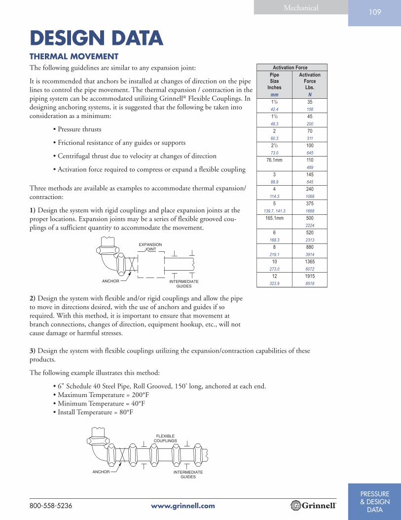
DESIGN DATA
www.grinnell.com800-558-5236
PRESSURE& DESIGN
DATA
Mechanical109
Three methods are available as examples to accommodate thermal expansion/contraction:
1) Design the system with rigid couplings and place expansion joints at theproper locations. Expansion joints may be a series of flexible grooved cou-plings of a sufficient quantity to accommodate the movement.
2) Design the system with flexible and/or rigid couplings and allow the pipeto move in directions desired, with the use of anchors and guides if sorequired. With this method, it is important to ensure that movement atbranch connections, changes of direction, equipment hookup, etc., will notcause damage or harmful stresses.
Activation Force
Pipe Activation
Size Force
Inches Lbs.
mm N
11/4 35
42.4 156
11/2 45
48.3 200
2 70
60.3 311
21/2 100
73.0 645
76.1mm 110
489
3 145
88.9 645
4 240
114.3 1068
5 375
139.7, 141.3 1668
165.1mm 500
2224
6 520
168.3 2313
8 880
219.1 3914
10 1365
273.0 6072
12 1915
323.9 8518
THERMAL MOVEMENTThe following guidelines are similar to any expansion joint:
It is recommended that anchors be installed at changes of direction on the pipelines to control the pipe movement. The thermal expansion / contraction in thepiping system can be accommodated utilizing Grinnell® Flexible Couplings. Indesigning anchoring systems, it is suggested that the following be taken intoconsideration as a minimum:
• Pressure thrusts
• Frictional resistance of any guides or supports
• Centrifugal thrust due to velocity at changes of direction
• Activation force required to compress or expand a flexible coupling
3) Design the system with flexible couplings utilizing the expansion/contraction capabilities of theseproducts.
The following example illustrates this method:
• 6" Schedule 40 Steel Pipe, Roll Grooved, 150' long, anchored at each end.• Maximum Temperature = 200°F• Minimum Temperature = 40°F• Install Temperature = 80°F

DESIGN DATA
www.grinnell.com 800-558-5236
PRESSURE& DESIGN
DATA
Mechanical110
To calculate the number of couplings required inthis example to compensate for the Thermal Expan-sion and Contraction of the pipe:
1) Thermal ContractionUtilize the Thermal Expansion Table. Allowance forinstallation temperature to the minimum tempera-ture, in this case 80°F to 40°F is calculated as:
80°F = 0.61" per 100'40°F = 0.30" per 100'Difference = 0.31" per 100'
For 150' of pipe = 0.31" x 1.5 = 0.47" per 150'
2) Thermal ExpansionUtilize the Thermal Expansion Table. Allowance forinstallation temperature to the minimum tempera-ture, in this case 80°F to 200°F is calculated as:
200°F = 1.52" per 100'80°F = 0.61" per 100'Difference = 0.91" per 100'
For 150' of pipe = 0.91" x 1.5 = 1.36" per 150'
Mean Coef. of thermal expansion = 0.00000633 in/in/°F
Source: ASME B31.9
Thermal Expansion of Carbon Steel inInches/100 Feet (Millimeters/30.5Meters)
Between 0°F (-18°C) & Indicated TemperatureTemperature Inches/100 Feet
F° (C°) (mm/30.5M)
-40 (-40) -0.30 (-7.62)
-30 (-34.4) -0.23 (-5.84)
-20 (-28.9) -0.15 (-3.81)
-10 (-23.3) -0.08 (-2.03)
0 (-17.8) 0.00 (0.00)
10 (-12.2 ) 0.08 (2.03)
20 (-6.7) 0.15 (3.81)
30 (-1.1) 0.23 (5.84)
40 (4.4) 0.30 (7.62)
50 (10.0) 0.38 (9.65)
60 (15.6) 0.46 (11.68)
70 (21.1) 0.53 (13.46)
80 (26.7) 0.61 (15.50)
90 (32.2) 0.68 (17.27)
100 (37.8) 0.76 (19.30)
110 (43.3) 0.84 (21.34)
120 (48.9) 0.91 (23.11)
130 (54.4) 0.99 (25.15)
140 (60.0) 1.06 (26.92)
150 (65.6) 1.14 (28.96)
160 (71.1) 1.22 (30.99)
170 (76.7) 1.29 (32.77)
180 (82.2) 1.37 (34.80)
190 (87.8) 1.44 (36.58)
200 (93.3) 1.52 (38.61)
210 (98.9) 1.60 (40.64)
220 (104.4) 1.67 (42.42)
230 (110.0) 1.75 (44.45)
THERMAL MOVEMENT3) Couplings RequiredAvailable linear movement for a 6" Figure 707Flexible Couplings on roll grooved pipe = 0.094"per coupling.
a) Fully Butted Together for Contraction OnlyTherefore the number of flexible Figure 707.Couplings required:
• 0.47" / 0.094" per coupling = 5.0• Use 5 Figure 707 Couplings for pipe contraction
b) Fully Gapped Apart for Expansion OnlyTherefore the number of flexible Figure 707.Couplings required:
• 1.36" / 0.094" per coupling = 14.47• Use 15 Figure 707 Couplings for pipe expansion

DESIGN DATA
www.grinnell.com800-558-5236
PRESSURE& DESIGN
DATA
Mechanical111
R =
L = (2) (R) (Sin )
N =
R = Radius of curve
L = Pipe length
= Deflection from centerline, in degrees, for each coupling (see table)
N = Number of flexible couplings needed
T = Total deflection, in degrees, required
T
MISALIGNMENT AND DEFLECTIONGrinnell® flexible couplings provide forrestrained joints and allow for deflection to aidwhere the pipe or equipments is misaligned.
Note that flexible couplings will not accom-modate both full maximum linear movementand the maximum available angular deflectionconcurrently at the same joint.
Design Deflection for Roll Grooved Pipe
Deflection O
(Roll Grooved Pipe)
Pipe Figures
Size 705
Inches &
mm 707
11/4 1.08°
42.4
11/2 0.94°
48.3
2 0.75°
60.3
21/2 0.62°
73.0
76.1mm 0.60°
3 0.51°
88.9
4 1.19°
114.3
5 0.97°
139.7, 141.3
165.1mm 0.83°
6 0.81°
168.3
8 0.63°
219.1
10 0.50°
273.0
12 0.42°
323.9
Incorporates the recommended safety factor reduction for field
practices (50% for sizes 11/4" - 3" and 25% for sizes 4" - 12").
If it is desired to have both deflection and linearmovement available, then the system should havesufficient flexible joints to accommodate therequirement.
Flexible couplings are also useful in laying outcurved piping systems.
L(2) (Sin )
2
2

DESIGN DATA
www.grinnell.com 800-558-5236
PRESSURE& DESIGN
DATA
Mechanical112
All piping systems require that the support system accommodate the weight of the pipe, joint connections,fluid and other system components. In addition, consideration may be necessary in reducing stresses, accom-modating thermal expansion or contraction, building settlement, seismic movement, etc. The followingtables provide guidelines for grooved steel piping products without concentrated loads between supports.
I - Spacing by ANSI B31.1 Power Piping Code
II - Spacing by ANSI B39.1 Building Piping Code
Pipe Suggested Maximum Span
Size Between Supports - Meters/Feet
Inches Water Service Air Service
mm I II I II
11/4 7 11 9 11
42.4 2.1 3.4 2.7 3.4
11/2 7 12 9 13
48.3 2.1 3.7 2.7 4.0
2 10 13 13 15
60.3 3.0 4.0 4.0 4.6
21/2 11 14 14 16
73.0 3.4 4.3 4.3 4.9
76.1mm 11 14 14 16
3.4 4.3 4.3 4.9
3 12 15 15 17
88.9 3.7 4.6 4.6 5.2
4 14 17 17 21
114.3 4.3 5.2 5.2 6.4
5 16 19 20 24
141.3 4.9 5.8 6.1 7.3
165.1mm 17 20 21 25
5.2 6.1 6.4 7.6
6 17 20 21 25
168.3 5.2 6.1 6.4 7.6
8 19 21 24 28
219.1 5.8 6.4 7.3 8.5
10 19 21 24 31
273.0 5.8 6.4 7.3 9.4
12 23 21 30 33
323.9 7.0 6.4 9.1 10.1
14 23 21 30 33
355.6 7.0 6.4 9.1 10.1
16 27 21 35 33
406.4 8.2 6.4 10.7 10.1
18 27 21 35 33
457.2 8.2 6.4 10.7 10.1
20 30 21 39 33
508.0 9.1 6.4 11.9 10.1
24 32 21 42 33
609.6 9.8 6.4 12.8 10.1
Number of Hangers Per Pipe Length
Pipe Pipe Length in Feet/Meters
Size 10 12 15 22 25 30 35 40
Inches 3.3 3.7 4.6 6.7 7.6 9.1 10.7 12.2
mm Avg. Hangers Per Pipe Length
1 1/4 - 2 2 2 2 3 4 4 5 6
42.4 - 60.3
2 1/2 - 4 1 2 2 2 2 3 4 4
73.0 - 114.3
5 - 24 1 1 2 2 2 3 3 3
139.7 - 609.6
For pipe runs when linear movement is accommo-dated by the flexible coupling:
For pipe runs when linear movement is not re-quired:
Note: The requirements of ANSI, ASME or other code groups may
require additional supports.
PIPE SUPPORT
Flexible Joints
Distance Between Supports
Nominal Maximum Distance
Size Between Supports
Inches Feet
mm Meters
11/4 - 11/2 12
42.4 - 48.3 3.7
2 - 8 15
60.3 - 219.1 4.6
10 - 12 16
273.0 - 323.9 4.9
14 - 16 18
355.6 - 406.4 5.5
18 - 24 20
457.2 - 609.6 6.1
For pipe runs with rigid couplings:Rigid Joints

DESIGN DATA
www.grinnell.com800-558-5236
PRESSURE& DESIGN
DATA
Mechanical113
ROTATIONAL MOVEMENTGrinnell® flexible couplings are suitable for use in seismic as well as mining applications. The inherentcapability of the flexible coupling to allow for linear movement, angular deflection, and rotational move-ment, make it an excellent choice for reducing stresses in a piping system and to increase pipe life in slurryapplications.
For mining applications where the pipe needs to be rotated, the system should be depressurized. The pipecouplings bolts/nuts can be loosened, pipe rotated and the bolts/nuts re-tightened and the system be putback in service.
Even distribution of pipe wear can be achieved with this method on the inner service of the pipe.Note: Precautions are necessary to monitor pipe wall thickness to evaluate pressure capability of the pipe withreduced wall.
LINEAR MOVEMENTFlexible couplings are designed with the couplings keys engaging the pipe without gripping on the bottom ofthe groove while still providing for a restrained mechanical joint.
The inherent flexibility of the coupling must be considered when deciding on support arrangements for thepiping system as movement can occur in more than one plane (linear movement, angular deflection androtational movement).
Upon system pressurization, each pipe end within the flexible couplings will expand to the maximumpublished value. The coupling keys make contact with the face of the groove and restrain the joint. In pipingsystems, this movement will be accumulative.

DESIGN DATA
www.grinnell.com 800-558-5236
PRESSURE& DESIGN
DATA
Mechanical114
ANGULAR MOVEMENT
System movement can be accommodated by providing for sufficient offsetlengths. Temperature increases/decreases can further increase this movement.
When systems are anchored with partially deflected joints, the systemcan move to the fully deflected condition upon pressurization resultingin the “snaking” of the piping system. Light weight hangers may not besuitable to prevent the lateral motion.
Pipe hanger positioning is important when considering pipe “sagging”due to the flexible nature of the piping system. Proper positioning ofhangers near the elbow, for example, should be considered.
The use of spring hangers or other methods can be considered toaccommodate vibrations. Base supports, pressure thrust anchors andpipe offsets can be used to direct pipe movement.
The use of rigid couplings can be considered to reduce the movementavailable with flexible couplings. Consideration to other methods ofaccommodation of pipe movements may be required.
PIPE SUPPORT
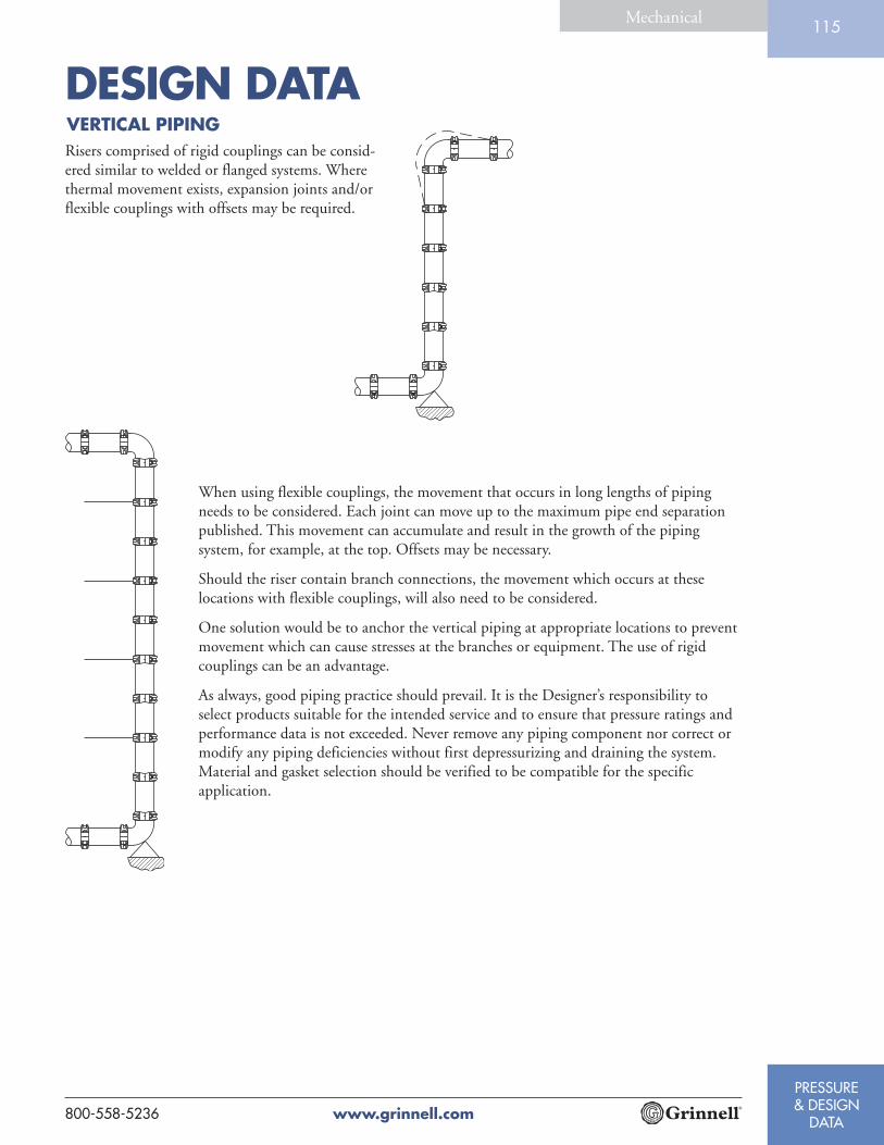
DESIGN DATA
www.grinnell.com800-558-5236
PRESSURE& DESIGN
DATA
Mechanical115
VERTICAL PIPINGRisers comprised of rigid couplings can be consid-ered similar to welded or flanged systems. Wherethermal movement exists, expansion joints and/orflexible couplings with offsets may be required.
When using flexible couplings, the movement that occurs in long lengths of pipingneeds to be considered. Each joint can move up to the maximum pipe end separationpublished. This movement can accumulate and result in the growth of the pipingsystem, for example, at the top. Offsets may be necessary.
Should the riser contain branch connections, the movement which occurs at theselocations with flexible couplings, will also need to be considered.
One solution would be to anchor the vertical piping at appropriate locations to preventmovement which can cause stresses at the branches or equipment. The use of rigidcouplings can be an advantage.
As always, good piping practice should prevail. It is the Designer’s responsibility toselect products suitable for the intended service and to ensure that pressure ratings andperformance data is not exceeded. Never remove any piping component nor correct ormodify any piping deficiencies without first depressurizing and draining the system.Material and gasket selection should be verified to be compatible for the specificapplication.

TYPICAL GENERAL & GUIDESPECIFICATIONS
www.grinnell.com 800-558-5236
PRESSURE& DESIGN
DATA
Mechanical116
TYPICAL GENERAL SPECIFICATION(CSI - Div. 15, Section A Info., Methods, & Instructions)
SECTION 1 - GROOVED PIPING METHOD
Grinnell® mechanical pipe couplings, grooved end fittings, groovedend butterfly and check valves, and other system components asmanufactured or supplied by Tyco Fire & Building Products shall beused to install piping systems and make mechanical equipmentconnections in systems within specified operating conditions; andworking pressures as shown in the coupling manufacturer’s productspecification. Grinnell mechanical pipe couplings shall be used for thefollowing systems (subject to applicable local code approval).
PLUMBINGDomestic Hot WaterDomestic Cold WaterRoof Drains/Storm Drains
HEATING / AIR CONDITIONINGChilled Water Hot WaterCondenser Water HeatingCooling Tower Dual TemperatureMachinery Room Utility Water
OTHERVacuum LubricationAir Pneumatic ConveyorElevator Hydraulic Low Temperature
TYPICAL GUIDE SPECIFICATIONBasic Materials & Methods (CSI - Div. 15 Section 15050)
SECTION 1 - MATERIALS - PIPE & PIPE FITTINGS
1.1 Pipe - Pipe shall conform to Grinnell published tolerancespecifications. Steel pipe shall be black or galvanized,conforming to ASTM A-135, A-795 or A-53.
1.2 Couplings - Couplings shall be Grinnell Figures 705, 707, 772and 716 cast in ductile iron as specified in ASTM A-536.Couplings shall have nuts and bolts. Couplings shall be coatedwith a lead free paint as standard, or hot-dipped galvanized inaccordance with ASTM A-153 as an option.
Couplings shall be Grinnell Figures 405 and 472 cast inStainless Steel as specified in ASTM A-743/A-743M. Couplingsshall have nuts and bolts.
1.2.1 Gaskets - Gaskets shall be a pressure responsive design,molded of synthetic elastomer as designated by ASTMD-2000, and shall conform to the coupling housing andpipe outside diameter. Reference shall be made to thelatest published Grinnell gasket selection guide forproper gasket selection for the intended service.
1.2.1.1 Water Service - Gasket shall be Grade“E” EPDM with green color code identifica-tion, for service temperatures from -30°F (-34°C) to 230°F (110°C). Recommended forhot water not to exceed 230°F (110°C), plusa variety of dilute acids, oil free air and manychemical services.
Not recommended for petroleum services or steam.
1.2.1.2 Oil Service - Gasket shall be grade “T” Nitrilewith orange color code identification, forservice temperatures from -20°F (-29°C) to180°F (82°C). Recommended for petroleumproducts, vegetable oils, mineral oils, and airwith oil vapors.
1.2.1.3 Other Services - Refer to the latest publishedGrinnell gasket selection guide for otherservice recommendations.
1.2.2 Bolts and Nuts - Shall be heat treated carbon steel, oval-neck track head bolts and heavy hex nuts, conforming tothe physical properties of ASTM A-183 with aminimum tensile strength of 110,000 psi. Bolts and nutsshall be zinc electroplated.
1.3 Flanges - Shall be Grinnell Figure 71 Flange, casting in ductileiron in accordance with ASTM A-536. Flange shall conform toANSI Class 125 and 150 bolt patterns and shall be coated witha lead-free paint as standard, or hot dipped galvanized inaccordance to ASTM A-153.
1.4 Fittings - Shall be ASTM A-536 ductile iron or fabricated fromsteel pipe, 11/4" (32mm) - 24" (600mm). All fittings shall becoated with a lead-free paint as standard, or hot-dippedgalvanized as an option in accordance to ASTM A-153.
1.5 Branch Outlets - Shall be Grinnell Figure 730 mechanical teesor crosses with integral gasket. Figure 730 shall be coated with alead-free paint as standard, or hot-dipped galvanized as anoption.
1.6 Butterfly Valves - Shall be with grooved ends. Valves shall haveencapsulated Grade “E” EPDM or Grade “T” Nitrile disc andrated at 300 psi bubble-tight-shut-off. Reference shall be madeto the latest published Grinnell gasket selection guide forproper disc seal selection for the intended service. Valve bodiesshall be ductile iron, and upper stems shall be stainless steel.
1.7 Check Valves - Shall be with grooved ends. Valves shall have aresilient elastomer seal Grade “E” EPDM or Grade “T” Nitrileand rated at 300 psi. Reference shall be made to the latestpublished Grinnell gasket selection guide for proper sealselection for the intended service. Valve bodies shall be ductileiron with a nickel seat. The caps shall be dutile iron with anattached stainless steel clapper assembly for 2" (60.3mm) - 8"(219.1mm) and a ductile iron clapper assembly for 10"(273.0mm) - 12" (323.9mm). All bodies and caps shall becoated with a lead-free paint as standard.
SECTION 2 - MATERIALS - PIPE PREPARATION
Pipe shall be prepared according to Grinnell® published specifications,ANSI/AWWA C-606, or other applicable standards.
2.1 Pipe Ends - Shall be clean and free from indentations,projections, burrs, rust or roll marks in the area from pipe endto groove.
2.1.1 Standard Weight Pipe - Shall be roll grooved withoutremoving metal, or cut grooved in accordance withGrinnell published standard roll groove or standard cutgroove specifications.
2.1.2 Lightwall Pipe - Shall be roll grooved without metalremoval in accordance with Grinnell published standardroll groove specifications.

PRESSURE& DESIGN
DATA
Mechanical
GUIDE & BUILDING SERVICESYSTEM SPECIFICATIONS
www.grinnell.com800-558-5236
117
TYPICAL GUIDE SPECIFICATION ASTM A-135, A-795 or A-53. All pipe shall be preparedaccording to Grinnell published specifications, or toANSI/AWWA C-606 grooved end pipe. Pipe ends shallbe prepared as detailed in Basic Materials and Methodsand to the latest Grinnell published specifications.
1.1.2 Couplings - All Grinnell grooved couplings and fittingsshall be painted or galvanized Figure 705, 707, 772 or716 with Grade “E” EPDM gaskets and zinc plated boltsand nuts.
1.1.3 Branch Connections - Shall be made with Figure 730and/or Figure 40-5.
1.1.4 Flange Connections - Flange connections shall beGrinnell Figure 71 Flanges incorporating Grade “E”EPDM gasket.
1.1.5 Fittings - Fittings shall be painted or galvanized Grinnellstandard ductile iron or segmentally welded steelfittings, with grooved ends.
1.1.6 Butterfly Valves - Shall be of grooved end design with aGrade “E” EPDM encapsulated disc. Upper stem shallbe stainless steel. Valves shall have pressure assisteddouble seal and be capable of 300 psi, bubble-tight-shut-off. Butterfly valves shall be with gear actuator or handlever. Operating conditions not to exceed -30°F (-34°C)to 230°F (110°C).
1.1.7 Check Valves - Shall be of grooved end design with aclapper seal of Grade “E” EPDM. Valves shall be capableof pressures of 300 psi. The valves shall have a spring-loaded clapper to ensure a leak tight seal and a non-sticking operation. The clapper seat in the valve bodyshall be nickel. Operating conditions not to exceed -30°F (-34°C) to 230°F (110°C).
SECTION 2 - STORM DRAINS / ROOF DRAINS
Grinnell mechanical grooved pipe couplings and fittings as manufac-tured by Tyco Fire & Building Products shall be used for all storm androof drainage systems.
2.1 Materials:
2.1.1 Pipe - Pipe shall be galvanized steel pipe, conforming toASTM A-135, A-795 or A-53. All pipe shall be preparedaccording to Grinnell published specifications, or toANSI/AWWA grooved end pipe. Pipe ends shall beprepared as detailed in Basic Materials and Methods andto the latest Grinnell published specifications.
2.1.2 Couplings - Couplings shall be galvanized Figure 705,707, 772 or 716 with Grade “E” EPDM gaskets andzinc plated bolts and nuts.
2.1.3 Flange Connections - Flange connections shall begalvanized Grinnell Figure 71 Flanges incorporatingGrade “E” EPDM gasket.
2.1.4 Fittings - Fittings shall be galvanized Grinnell standardductile iron or segmentally welded steel fittings, withgrooved ends.
2.2 Plastic Pipe Systems
2.2.1 Pipe - Pipe with material and dimensions conforming toASTM D-1785 Type 1, Grade 1 with rolled or radiuscut grooves and joint pressure ratings conforming togrooved manufacturer’s specifications or recommenda-tions; or Type 2, Grade 1 with rolled or radius cutgrooves and joint ratings conforming to groovedmanufacturer’s specifications and recommendations.
Plumbing Specifications (CSI - Div. 15 Section 15-E Plumbing)
SECTION 1 - DOMESTIC WATER SYSTEMS
(CSI - Div. 15, Section 15-E Water Supply Systems)
Grinnell Mechanical Grooved Pipe couplings, fittings and butterflyvalves as manufactured or supplied by Tyco Fire & Building Productsshall be used for all water supply systems under operating conditionsnot to exceed 230°F (110°C) temperature. The coupling gasket andencapsulated disc on butterfly valves shall be Grade “E” EPDM.
1.1 Materials:
1.1.1 Pipe - Pipe shall be galvanized steel pipe, conforming to
Continued
SECTION 3 - ASSEMBLY
3.1 Grinnell couplings, fittings, flanges and valves shall beassembled in accordance with instructions published by TycoFire & Building Products.
3.1.1 Pipe - Ends shall be clean and free from indentations,projections, burrs, roll marks, etc., in the area from pipeend to groove. Pipe ends shall be square cut andprepared in accordance with standard Grinnellspecifications.
3.1.2 Gasket - Shall be of pressure responsive design verified asproper style and grade suitable for the intended serviceas published in the latest Grinnell gasket recommenda-tion technical literature.
3.1.3 Lubrication - A thin, uniform coat of Grinnell lubricantshall be applied to the entire exterior of the gasket,including the gasket lips. Complete lubrication isessential to prevent gasket pinching and to easeinstallation and alignment. Petroleum-free silicon gasketlubricant is recommended when gaskets are subject tolow temperature conditions. Petroleum lubricants shallnot be used for EPDM gaskets.
SECTION 4 - SUPPORT
4.1 Horizontal Piping: (contact Tyco Fire & Building Products forsupport recommendations)
4.1.1 Flexible Connections - No pipe length shall be leftunsupported between any two couplings, nor shall anypipe be left unsupported whenever a change in directionof line flow takes place. Supports shall meet therequirements stated above, but in no case shall thedistance between supports exceed the following forsystems where linear movement is not required:
Pipe Size Span Pipe Size Span
Inches Feet Inches Feet
mm Meters mm Meters
11/4 - 11/2 12 14 - 16 18
42.4 - 48.3 3.7 355.6 - 406.4 5.5
2 - 8 15 18 - 24 20
60.3 - 219.1 4.6 457.2 - 609.6 6.1
10 - 12 16
273.0 - 323.9 4.9
4.1.2 Rigid Connections - Pipe connections formed with theFigure 772 shall be supported in accordance withapplicable ANSI B31.1, Power Piping Code; ANSIB31.9, Building Service Pipe Code.
TYPICAL SPECIFICATIONSBuilding Service Systems - Plumbing
BUILDING SERVICE SYSTEMSPECIFICATIONS
www.grinnell.com 800-558-5236
PRESSURE& DESIGN
DATA
Mechanical118
TYPICAL SPECIFICATIONSBuilding Service Systems - PlumbingSECTION 2 - STORM DRAINS / ROOF DRAINSContinued
2.2.2 Couplings - Flexible type couplings shall be used.
2.2.3 Flange Connections - Same as in 2.1.3
2.2.4 Fittings - Same as in 2.1.4
SECTION 3 - VENT PIPING
(Same as in Section 2 - Storm Drains / Roof Drains)
Building Service Systems - CoolingCooling System Specifications (CSI - Div. 15 Section 15-N Refrigera-tion Systems)
SECTION 1 - CHILLED WATER - SUPPLY & RETURN
Grinnell® Mechanical Grooved Pipe couplings, fittings and butterflyand check valves as manufactured or supplied by Tyco Fire & BuildingProducts shall be used for cooling system chilled water piping,including risers, mains, equipment connection, branches, supply andreturn lines under operating conditions not to exceed -30°F (-34°C) -230°F (110°C) temperature. Calculations shall be made based oncoupling manufacturers latest literature to determine expansion/contraction allowance available, enabling elimination of specialmovement compensators, swing joints, flexible connections andvibration isolators where possible.
1.1 Materials:
1.1.1 Pipe - Shall be steel pipe, conforming to ASTM A-135,A-795 or A-53. All pipe shall be prepared according toGrinnell published specifications, or to ANSI/AWWAC-606 grooved end pipe. Pipe ends shall be prepared asdetailed in Basic Materials and Methods.
1.1.2 Couplings - All flexible couplings shall be GrinnellFigure 705 and 707 with Grade “E” EPDM gaskets andzinc plated bolts and nuts. All rigid couplings shall beGrinnell Figure 772 with Grade “E” EPDM gaskets andzinc plated bolts and nuts.
1.1.3 Branch Connections - Branch stub-in connections shallbe made with Figure 730 with Grade “E” EPDM gasketsand zinc plated bolts and nuts.
1.1.4 Flange Connections - Shall be Grinnell Figure 71 Flangeincorporating Grade “E” EPDM gasket.
1.1.5 Fittings - Shall be Grinnell ductile iron or segmentallywelded steel fittings, with grooved ends.
1.1.6 Butterfly Valves - Shall be of grooved end design withEPDM encapsulated disc. Neck design shall readilyaccommodate insulation. Valves shall have pressureassisted double seal and stainless steel upper stems, andbe capable of 300 psi, bubble-tight-shut-off, with anactuator or hand lever.
1.1.7 Check Valves - Shall be of grooved end design with aclapper seal of EPDM. The valves shall have a spring-loaded clapper to ensure a leak tight seal and a non-sticking operation. The clapper seat in the valve bodyshall be nickel. Valves shall be capable of pressures of300 psi.
SECTION 2 - COOLING TOWER PIPING
Same as Section 1, except pipe, couplings and fittings shall begalvanized.
SECTION 3 - DUAL TEMPERATURE SYSTEMS PIPING
Same as Section 1.
SECTION 4 - CONDENSER WATER PIPING
Same as Section 1.
Building Service Systems - HeatingHeating System Specifications (CSI - Div. 15 Section 15-L WaterPiping)
SECTION 1 - HOT WATER HEATING SYSTEMS - SUPPLY &RETURN
Grinnell Mechanical Grooved Pipe couplings, fittings and butterflyand check valves as manufactured or supplied by Tyco Fire & BuildingProducts shall be used for hot water systems , including boilermanifolds, mains, risers, branches, supply and return lines, underoperating conditions not to exceed 230°F (110°C). Calculations shallbe based on coupling manufacturers latest literature to determineexpansion allowance available, enabling elimination of specialexpansion compensators, swing joints, flexible connections andvibration isolators where possible.
1.1 Materials:
1.1.1 Pipe - Shall be steel pipe, conforming to ASTM A-135,A-795 or A-53. All pipe shall be prepared according toGrinnell published specifications, or to ANSI/AWWAC-606 grooved end pipe. Pipe ends shall be prepared asdetailed in Basic Materials and Methods.
1.1.2 Couplings - All flexible couplings shall be GrinnellFigure 705 and 707 with Grade “E” EPDM gaskets andzinc plated bolts and nuts. All rigid couplings shall beGrinnell Figure 772 with Grade “E” EPDM gaskets andzinc plated bolts and nuts. All reducing couplings shallbe Grinnell Figure 716 with Grade “E” EPDM gasketsand zinc plated bolts and nuts.
1.1.3 Branch Connections - Branch stub-in connections shallbe made with Grinnell Figure 730 with Grade “E”EPDM gaskets and zinc plated bolts and nuts.
1.1.4 Flange Connections - Flange connections shall beGrinnell Figure 71 Flange incorporating Grade “E”EPDM gasket.
1.1.5 Fittings - Fittings shall be Grinnell ductile iron orsegmentally welded steel fittings, with grooved ends.
1.1.6 Butterfly Valves - Shall be of grooved end design withEPDM encapsulated disc. Neck design shall readilyaccommodate insulation. Valves shall have pressureassisted double seal and stainless steel upper stems, andbe capable of 300 psi, bubble-tight-shut-off, with anactuator or hand lever.
1.1.7 Check Valves - Shall be of grooved end design with aclapper seal of EPDM. The valves shall have a spring-loaded clapper to ensure a leak tight seal and a non-sticking operation. Valves shall be capable of pressures of300 psi.

Limited Warranty
Products manufactured by TFBP are warranted solely to the original Buyer for ten (10) years against defects in material and workmanship when paid for and properly installed and maintained under normal use and service. This warranty will expire ten (10) years from date of shipment by TFBP. No warranty is given for products or components manufactured by companies not affiliated by ownership with Tyco Fire & Building Products or for products and components which have been subject to misuse, improper installation, corrosion, or other external sources of damage or which have not been installed, maintained, modified or repaired in accordance with TFBP’s installation instructions. Materials found by TFBP to be defective shall be either repaired or replaced, at TFBP’s sole option. TFBP neither assumes, nor authorizes any person to assume for it, any other obligation in connec-tion with the sale of products or parts of products. TFBP shall not be responsible for mechanical and/or sprinkler system design errors or inaccurate or incomplete information supplied by Buyer or Buyer’s representatives.
IN NO EVENT SHALL TFBP BE LIABLE, IN CONTRACT, TORT, STRICT LIABILITY OR UNDER ANY OTHER LEGAL THEORY, FOR INCIDENTAL, INDIRECT, SPECIAL OR CONSEQUENTIAL DAMAGES, INCLUDING BUT NOT LIMITED TO LABOR CHARGES, REGARDLESS OF WHETHER TFBP WAS INFORMED ABOUT THE POSSIBILITY OF SUCH DAMAGES, AND IN NO EVENT SHALL TFBP’S LIABILITY EXCEED AN AMOUNT EQUAL TO THE SALES PRICE.
The foregoing warranty is made in lieu of any and all other warranties express or implied, including warranties of merchantability and fitness for a particular purpose.

Mechanical Products
USA
Customer ServiceOak Creek, WIToll Free: 800 558-5236Fax: 800 877-1295
Technical ServicesTel: 866 500-4768Fax: 401 781-7317
EUROPE & MIDDLE EAST
Tyco Building Services ProductsKopersteden 1, NL-7547 TJ EnschedeP.O. Box 198, 7500 ADEnschede, The NetherlandsTel: 31-53-428-4444Fax: 31-53-428-3377
ASIA
Tyco Fire & Building Products Asia45 Tuas Avenue 9Singapore 639189Tel: +65-6861-1655Fax: +65-6861-1312
AUSTRALIA
Tyco Flow Control - Fixed Fire567 Somerville RoadSunshine, Melbourne VIC 3020Tel: 13-0072-5688Fax: 03-9933-6204
Grinnell, G FOUNDED 1850 and Design, and Tyco are either registered trademarks or trademarks of Tyco and/or its affiliates in the United States and/or other countries.© Tyco Fire Products LP. All rights reserved. / Printed in USA / GMCAT / 5M / ABP / 04-06
www.grinnell.com
GRInnELL MEchAnIcAL PRODUcTS
M
echanical Products
M06-1