Lightweight Solar Power Constellation
37
Lightweight Solar Power Constellation Solving the Space Solar Power Puzzle Members Sam Albert , [email protected] 1 Noah Marquand 1 , [email protected] Jacob Nunez-Kearny 1 , [email protected] Michael Thompson 1 , [email protected] Mentor Denis Curtin 2 1 Purdue University, School of Aeronautics and Astronautics, Undergraduate Student 2 Society of Satellite Professionals International
Transcript of Lightweight Solar Power Constellation

Lightweight Solar Power Constellation Solving the Space Solar Power Puzzle
Members Sam Albert , [email protected] 1
Noah Marquand1, [email protected] Jacob Nunez-Kearny1, [email protected] Michael Thompson1, [email protected]
Mentor
Denis Curtin 2
1 Purdue University, School of Aeronautics and Astronautics, Undergraduate Student 2 Society of Satellite Professionals International

1
Table of Contents Abstract……………………………………………………………………………………...........2 Introduction to Space-Based Solar Power…………………………………………….………..3 Technical Requirements…………………………………………………………………............4 Array Structure………………………………………………………………………….……….5
Hub and Spoke…………………………………………………………….………............5 Constellation……………………………………………………………..………………..7 Benefits of Multi-Satellite Structure………………………………..……………………..8
Solar Energy Collection………………………………………………….….……………….....10 Lightweight Deployable Mirror………………………………….….…………………...10 Concentrated Solar Energy Cell……………………………….……..…………………..12
Orbital Design…………………………………………………………………...……………...14 Time Exposed to Sunlight……………………………………………...………………...14 Ground Track Management……………………………………………...……………....15 Design Choice…………………………………………………………………………....15 Future Technology Improvements……………………………………………………….15
Power Transmission…………………………………………………………..………………...17 Background of Wireless Power Transmission…………………………………..……….17 System Design…………………………………………………………..…………….…18 DC-to-RF Power Conversion…………………………………………..………………...18 Microwave Array Antenna Transmission………………………………..………………19 Rectenna RF-to-DC Power Collection and Conversion…………………………………21 Summary………………………………………………………………..……………..…22
Launch Vehicles………………………………………………………………..…………….....23 Cost Estimation……………………………………………………………………..…………..26
Spoke Cost Estimation…………………………………………………………..……….26 Hub Cost Estimation………………………………………………………………..........26 Overall System Cost……………………………………………………………………..26 Learning Curve……………………………………………………………………..........28
Political and Regulatory Issues……………………..………………………………………….29 Conclusions and Recommendations………………………………..………………………….31 Bibliography…………………………………………………..…………………………...……33 Appendix……………………………………………………………………………………...…36

2
Abstract The design of the Lightweight Solar Power Constellation (LSPC) uses a constellation of
satellites to collect solar energy and beam it to the ground. The constellation uses a Spoke and Hub architecture: a set of smaller “spoke” satellites with large mirrors to reflect sunlight are launched with a single, larger “hub” satellite to collect and transmit the power to Earth.
The spoke satellite design uses a lightweight, highly reflective, mylar mirror to focus
sunlight. The hub design contains highly efficient concentrated solar cells to collect the reflected light. Power is beamed to the ground via microwave transmission from the hub. LSPC is placed in a GEO orbit by a single Falcon Heavy launch. A system of 15 spoke satellites with one hub satellite that can produce a range of seven to eleven MW depending on the time of day. The cost of a single system on a Falcon Heavy launch is $240 million. The LSPC will have political considerations with the amount of power moving through the low earth orbit band and the atmosphere. The total efficiency of the LSPC from collecting solar power to electrical energy in the grid is 21.98% with a collection rate of 300W/m2.

3
Introduction to Space-Based Solar Power
Currently, one of the most important issues facing the global community is the ongoing energy crisis, or the growing shortage of non-renewable energy sources. A related problem is the continuing buildup of CO2 and other greenhouse gases in the atmosphere. Thus, sources of clean, renewable energy remain a pressing requirement for the current and future generations. One common solution is solar power, but even if photovoltaic cells improve dramatically in efficiency, the inconsistency of sunlight due to weather, seasonal variation, and nighttime inherently limit solar power based on Earth. However, one can circumvent these limitations by collecting the solar power in space, where it is not only constant but significantly more intense, then beaming that power to Earth where it is collected and converted back into a usable form of energy. This concept, known as Space-Based Solar Power (SBSP) (sometimes also referred to as Solar-Power Satellite, or SPS), was first introduced in 1968 by Dr. Peter Glaser of the Arthur D. Little Company [1]. In its original form, sunlight would be captured by solar panels on a satellite in geosynchronous orbit then beamed back to Earth as microwave power. There have been many elaborations and variations on this design, but most models still more or less follow Dr. Glaser’s original patent.
Not long after Dr. Glaser’s patent was filed, a committee was formed by the Energy Research and Development Agency to study SBSP. By 1977, this committee had grown into a three-year program known as the DOE/NASA Satellite Power System Concept Development and Evaluation Program, which produced many studies and a 670-page document summarizing their findings [2]. While the study did not kill the concept, no follow-up program was created, and for a time the SBSP architecture stalled. Fortunately, by the 1990s, interest had picked up in Japan, Europe, and Canada, spurring NASA to conduct a “fresh look” report on the subject [3]. With the now-constant presence of clean energy in the sphere of discussion, along with technical advancements which have been made in space transportation, space structures, and solar power generation, the concept has again been receiving significant attention in the form of research and proposals. However, no proof-of-concept of the entire mission architecture has been conducted.

4
Technical Requirements
To create a successful design, technical requirements are needed to ensure the design meets all goals set out for by SEDS-SSPI. Set at the onset of the project, the technical requirements are the benchmarks believed to produce a design that is cost effective, feasible, and efficient.
Cost is the most important requirement in any space design, installations are considered
to be unrepairable and costs to launch require significant investment. The figure used to compare all power production systems is $/kW to adjust for larger systems producing more power. The next most important requirement is mass as a larger system is more expensive to put into orbit. A smaller system with the same power output could be launched with additional components. Similarly the number of launches required affects cost. Launching a complete system in two launches maximum establishes a functioning system during the time it would take to build a ground station, taking no additional time for installation over a single launch. 10 MW was chosen as the target output power as it is comparable to other power sources, but still small enough to be a proof of concept. A lower total system efficiency was chosen as the target value for the technical requirement of total system efficiency because of the known low efficiency of photovoltaic cells and the relatively unknown efficiency of wireless power transfer. The design has the technical requirement of being scalable in order to be a useful solution to the growing power needs. In this way, the project can prove its capabilities as a smaller project and then be scaled up to meet demand.
Technical Specifications
Technical Need Technical Requirement Target Value
Cost per System $/kW 20000
System Mass kg 3000
Number of Launches per System # 2
Total Output Power MW 10
Total System Efficiency % 20
Scalability Range 10kW-1GW

5
Array Structure Hub and Spoke
The LSPC utilizes a collection of satellites working in tandem to generate electrical power from solar energy. This collection is composed of two types of satellites, referred to as “spoke” and “hub” types. Spoke satellites serve as light collectors, directing light with large deployable mirrors. Hub satellites serve as energy transceivers, absorbing reflected light, converting it into electrical power, and then transmitting it to the ground via microwave power. Each orbital system would include a single hub satellite and a requisite number of spokes to direct a target amount of solar energy.
Spoke satellites would be outfitted with a large deployable mirror,
onboard solar cells and batteries, three axis torque wheels, three axis RCS thrusters, a simple CPU, and a radio transceiver. These systems would allow the spokes to communicate, perform maneuvers, collect power for on-board functions, and reflect light.
Spoke Satellite Hardware
Specification Component Notes
Reflective Surface Stowable Mirror Mylar, 92% reflectance [4], 25m radius
Correct Orientation Attitude Control System Low power torque wheel
Communications Radio 5.8Ghz Band [3]
Correct Position in Constellation CPOD Software
On-board Power Solar cells and Batteries Attached to mirror armature
Propulsion Thrust mass Three axis RCS
Radio and CPU systems would run in conjunction with other spokes to produce an active
data transfer network similar to NASA’s NODES project [5]. This network enables swarm communication, and therefore swarm maneuvering, by autonomously sending satellite signals as efficiently as possible. Accomplishing this requires a suite of sensors to construct a precise map of satellite positions and interference patterns, which the satellites then use to designate the best paths for signals to be sent between spokes. The final result is a branching network of communications which can be updated as spokes perform maneuvers or solar radio interference patterns shift.

6
Combined control systems of torque wheels and RCS thrusters yield a high degree of control over spokes for low amounts of power and fuel consumption. Torque wheels allow for continual adjustment of orientation without use of any propellant, meaning that spokes are not constrained to any given orientation throughout their orbit. As such, spokes adjust their attitude to best catch and direct the sunlight towards the hub. For more major corrections, the RCS thrusters could provide thrust for the craft, as minute drifting may occur over the mission, causing the spoke to shift out of position. Small adjustments from RCS thrusters could compensate for this drifting with assistance from software developed in NASA’s CPOD [6]. Once the craft is retired, the spoke’s thrusters would be capable of moving itself into a graveyard orbit away from the swarm.
Both maneuvers and communications rely on onboard electrical power generated from
small arrays of solar cells. Given that much of the satellite body will be blocked from the sun by the deployable mirror, these arrays will be distributed along the curved deployable mirror armature, meaning that when in operation, each spoke will be in a nearly continual supply of power as it orients itself to face the sun. More information on the deployable mirror is discussed later in the Solar Energy Collection section.
Hub satellites will be outfitted with a folding solar panel, a
panel cooling system, heat dissipation radiators, three axis torque wheels, three axis RCS thrusters with a universal fueling port, a CPU, a radio transceiver, and a microwave power transmitter. These systems will allow the hub satellite to operate with similar ease as the spokes, serving as the primary “captain” satellite in the constellation and handling communications with ground. Concentrated solar cells will fold outward to form the collection array. Thermal radiators will extend around the outer radius of the hub. The microwave transmitter will unfurl on the opposite side of the collection array. More information on these components can be found in the Power Transmission and Solar Energy Collection sections respectively.

7
Hub Satellite Hardware
Specification Component Notes
Power Collection Multi-junction concentrated solar cell
35% to 50% Efficiency [7]
Collection Cooling System Radiators with coolant Ammonia Cooling [8] / Liquid Droplet Radiator
Power Transmission Microwave transmitter 92.5% Efficiency [3]
Ground Station Tracking Gimbaling transmitter
Correct Orientation Attitude control system
Communications Radio 5.8Ghz Band [3]
On-board Power Solar cells and batteries
Propulsion Thrust mass Three axis RCS
Constellation Distribution
Satellites will be distributed throughout the constellation to collect as much solar irradiance as possible. Spoke satellites, shown below in green, will form a large reflector ring below the hub satellite, shown in yellow. Spokes will then be angled in a semi-parabolic shape as shown to reflect light towards another spoke acting as a secondary mirror, shown in blue, which reflects light to the hub solar panel.
However, as the LSPC orbits the earth, different parts of the constellation receive
different amounts of sunlight from different directions. In order to compensate, each spoke satellite continually reorients itself using the onboard maneuvering and sensory systems. By measuring differences in the voltages produced by the solar cells, light intensity can be calculated on each cell. These intensities may then be used to derive the sun’s position relative to the spoke. If this data is insufficient for any given spoke, it may then consult other spokes using the active data transfer network, sourcing as much solar cell data as possible to determine the

8
sun’s position. Once acquired, the spoke may use its orientation and position relative to the sun and hub to correct orientation and direct sunlight accordingly.
However, this process does not prevent the case of one spoke obstructing another’s sunlight, and spokes which reflect light at shallow angles present smaller area of capture to the sun, capturing less sunlight. Some of this may be avoided by distancing the spokes apart from one another, allowing light to shine between spokes and strike spokes inside the constellation with better alignment. Without continual thruster burn, shallow angles of
deflection cannot be corrected for. Analysis of three sun, constellation, and earth alignments indicated differing energy capture rates throughout a single orbit. These alignments are henceforth deemed normal, transverse, and reverse as pictured below. The normal alignment captures sunlight at the highest efficiency, featuring the steepest angles of deflection and no inter-spoke obstruction. The transverse alignment captures sunlight less efficiently; sunlight is deflected at nearly right angles and some inter-spoke obstruction is observed. Lastly, the reverse alignment captures sunlight the least efficiently, as most spokes demonstrate extremely shallow deflections, drastically reducing capture area. However, no inter-spoke obstruction is observed. During spring and fall, the earth’s shadow will obstruct the reverse alignment briefly, but will not affect power collection for other alignments with higher efficiencies, thus the majority of power collection is unaffected.
System Alignment Percentage of Effective Collector Area
Normal 95%
Transverse 75%
Reverse 60%
Benefits of Multi-Satellite Structure
Multi-satellite structure offers the unique benefits of having no single point of failure, updatable components, and scalability. The LSPC may be used in a variety of power outputs to cater to a wide range of demand, as new technologies are developed and old satellites are retired, new ones can take their place to prevent obsolescence, and in the event of satellite damage, the system can continue to operate.
9
In the event of a micrometeorite strike rendering a spoke satellite unusable, each spoke carries enough fuel to provide thrust corrections throughout its lifetime and adjust its orbit, meaning that an inoperable craft would be able to remove itself from the swarm and notify the ground station of a strike. Completely inoperable craft would not disrupt future power collection beyond minor obstruction and could potentially be removed by automated debris removal techniques currently in development. With every component being replaceable and largely non-essential, no single loss would be catastrophic to the constellation. Even in the event of hub loss, it being replaced would be a matter of launching another rather than constructing a new station.
As satellites are removed from the constellation, new ones may be added that better meet the needs of the system. Hardware compatibility need not be an issue without any physical connections between satellites, and software updates could be achieved through links to ground to accommodate new advancements. These new additions may not need dedicated launches and could potentially share a launch vehicle with other products, reducing overall expenditure.
The alternative solution to the issue lies in space-based assembly as seen in other
proposed designs [9]. While resulting in a more compact structure, this method requires a much larger investment, many times more craft types, and therefore complexity, and a much greater degree of precision in craft control, in addition to lacking the benefits listed above.

10
Solar Energy Collection As previously described, the LSPC utilizes a large swarm of “spoke” satellites, shown in
green, to reflect light towards another single spoke, shown in blue, which concentrates the swarm power onto the “hub” solar panel, shown in yellow. Spokes carry large deployable mirrors, redirecting sunlight based on orientation. The hub carries a folding solar panel, absorbing the reflected energy from the spokes and converting it to electrical power for microwave transmission to the ground.
Sunlight being received, focused, and transmitted
Lightweight Deployable Mirror
Upon reaching their target constellation position, spoke satellites will deploy onboard mirrors to begin collecting light and power. This mirror will be a large, curved surface bent to focus sunlight into a point on a target satellite. In order to expand and cover an effectively large surface, the mirror will be made of radiation-proofed mylar fabric attached to an extending boom armature. Under the current model, power collection increases as the collection area increases. Two solutions exist to this: large mirrors, or many mirrors. Each solution presents its own benefits and issues.
Large mirrors provide a high degree of control over light direction, solid surfaces can
reflect light against themselves to focus incoming light to a point as modern telescopes do. However, these mirrors are often extremely heavy and difficult to launch into space, needing to be multipart structures folded into place after achieving orbit. Small and numerous mirrors on the other hand are easier to pack within existing fairings, potentially even being able to be carried alongside other crafts as a secondary payload. Cubesats offer a powerful platform for this type of system, with long-term mission capability increasing via new thruster technologies developed for the 6U, 9kg system [10], but small mirrors present a much smaller target area for inter-satellite reflection, meaning that slight errors in attitude are much more problematic. Additionally, as the mirror component for satellites is typically the least dense component of the satellite, a cubesat would not provide as much collection area per unit mass. Compared to a commercial satellite of

11
200kg, the cubesat model would require twice as much mass to provide the same area. As such, large mirrors provide the better solution to the issue than small and numerous ones.
Mirrors used in current space technologies are generally used for space telescopes, most notably the Hubble and James Webb telescopes. The James Webb utilizes 18 separate beryllium segments to construct a 6.5m radius primary mirror [11]. This allows the mirror to be launched in a stowed state, and then unfurled upon being released from the fairing, demonstrating how mirrors can both be multipart and not be constrained by fairing circumference. In addition, beryllium is exceedingly strong and non-responsive to temperature fluctuation, making it ideal for a space mirror. However, large scale manufacturing for beryllium mirrors is exceedingly expensive; a circular mirror with a radius of 2.5m would cost up to 2.8 million dollars [12] using mass production techniques and supplementing beryllium with cheaper aluminum. Large scale mirrors are not feasible at such cost.
The Hubble telescope uses an aluminum coated silica-glass mirror , spanning 2.4m and having a mass of 826kg [13]. This large mass would significantly impact the usability of spoke satellites, large area satellites with the same material density as a Hubble mirror would require dedicated launch vehicles. Ignoring production costs, this expense in itself would be impractical.
A promising alternative to traditional metal space mirrors comes from solar sail design
[14]. Solar sails function as large, light solar mirrors, reflecting sunlight to impart momentum. These designs must expand to massive sizes, using compressed air to inflate extending booms and unroll large, flexible mirrors. These mirrors, typically made of materials like mylar, are extremely cheap, light, and reflective. Mylar itself is $3.95/m2 [15], making the cost of producing the mirrors nearly negligible, while the material density would be approximately 50g/m2 of mirror. In addition to these factors, mylar is relatively strong, its reinforced mesh making it unlikely to tear in the event of micrometeorite strike. Instead, any damage caused would be largely localized without worry for debris damaging the rest of the spoke or endangering other parts of the constellation. While being only 92% reflective [4] and requiring some radiation-proofing to prevent high energy degradation, these advantages make large area collector mylar mirrors the most practical option.
Large mirrors require some method of expansion and packing in order to be launched. As such, the circular spoke mirror will be deployed via compressed air booms and articulated armature to achieve a full radius of 25m. Once deployed, the spoke reflector will then be focused

12
upon the hub throughout slight curvature in the mirror, directing all incoming sunlight towards a single point. In doing so, the spoke ensures that no light is wasted and misses the hub; without curvature, sunlight would be reflected in a plane rather than directed beams, requiring a solar panel at least as large as the mirror to absorb all the light.
Concentrated Solar Energy Cell
The folding solar panel on the hub satellite is a highly efficient concentrated solar panel. To accommodate a 7-11 MW system, the folding panel would be a circle with a radius of 3.5m when extended. A circular panel is prefered for more efficient concentration of sunlight. Folded down this panel would easily fit inside the launch vehicle. For efficient packing the panel would fold in half on top of the center of the panel.
The type of solar panel used on the hub satellite is a III-V multi-junction solar cells concentrated photovoltaic (CPV) cell. This type of cell was chosen for its high efficiency at high intensities. Recent experiments have shown III-V multi-junction cells to have efficiencies in the range of 40-46% at concentrations of 200-1000 suns [16]. CPV’s have the potential to reach 50% efficiency within the coming decade, making a system similar to the LSPC even more promising [7].
Projected solar panel efficiencies by year [7]
For the LSPC, the hub satellite will use a 45% efficient system at concentrations of 400 suns. CPV’s function at lower sun concentrations, but have lower efficiencies. Since the hub’s solar panels require a large area of incident sunlight, a ratio of ~765m2:1m2 of mirror reflection area to panel collection area is required to reach the 400 sun concentration accounting for the inefficiencies of the absorbance and angles of the mirrors. A large cooling system will need to be in place as solar panel efficiency is directly related to temperature, losing efficiency with increases in temperature. The cooling system will utilize an ammonia-based heat transfer system

13
similar to the ISS [8], transported heat into a series of liquid droplet radiators [17]. While these radiators have yet to be sufficiently tested, they provide a lightweight, extremely efficient system for heat dissipation that would necessary for the intense thermal issues that would arise from uncooled units. In future, liquid droplets could be used in conjunction with thermo-electric power systems to capture more wasted energy and improve system output.
The advantage of CPV is that mirrors can be used as the effective collection area rather than solar panels. This leads to a lower total cost because mirrors are less expensive than solar panels. Accounting for the inefficiencies of a mirror and incident sunlight, the system would still be more efficient than solar panels covering the same area. Efficiency of the mirror-concentrated system is 92% for the reflectivity, 60% for the incident angles, and 45% for the efficient panel, totals 25%, versus 15% for low cost solar panels. The cost of the experimental CPV is unknown, but the reasoning for the design is that 63 m2 of expensive highly efficient solar panels is cheaper than 20000 m2 of less efficient, lower cost panels.

14
Orbital Design Space-based solar power systems have two key considerations in the area of orbital design: the time exposed to sunlight, and the resultant ground track of the orbit. Time Exposed to Sunlight
Given that the primary function of these systems is to collect solar power, an orbit should be designed to maximize the time spent in direct sunlight. For a circular orbit, this relationship is simple: as altitude increases, the fraction of time spent in sunlight approaches 100%. This fraction varies from 61% at the average altitude of the ISS in low Earth orbit to over 95% at the GEO band.
Type of Orbit Altitude (m) Fraction of orbit in sunlight
Low Earth Orbit 160,000 - 2,000,000 0.5706 - 0.7246
Medium Earth Orbit 2,000,000 - 35,786,000 0.7246 - 0.9517
High Earth Orbit 35,786,000 + 0.9517 +

15
Ground Track Management
Designing an appropriate ground track is important in the design of any satellite, but particularly so in the case of a space-based solar power satellite. The beaming of power to the ground requires either a ground track that stays relatively stationary for long periods of its orbit, multiple ground receiving stations to compensate for a changing ground track, or large battery systems to store energy until it can be transmitted. Design Choice
Given these constraints, our system is designed to operate in geostationary orbit (GEO). This orbit at 35,786 kilometers above the Earth’s equator provides sunlight for over 95% of each orbit and a stationary ground track over a point on the equator. Concepts involving sun-synchronous [18], or highly elliptical/Molniya [19] orbits seem promising and due to their lower altitudes could allow for large systems to be constructed and launched, but still require either multiple ground stations or large batteries to store the collected solar power until it can be transmitted. The primary drawbacks of the selection of GEO are the large delta-v costs required to place a satellite there, and the relative lack of serviceability if refueling or maintenance is required. However, in recent years, both of these barriers have become less crippling for satellite systems. Future Technology Improvements
Companies such as SpaceX have brought launch costs down in recent years, allowing for satellite systems to be launched to GEO at a lower cost. Cost aside, the physical constraints of sending limited payloads to GEO are also being loosened through advances and improvements in launch vehicles. A very promising development in the field of GEO satellites is the possibility of on-orbit refueling and maintenance. Orbital ATK has currently designed a Mission Extension Vehicle (MEV) to prolong the lifetime of satellites in the geostationary belt. The MEV physically attaches itself to a target satellite and has the ability to perform orbital upkeep maneuvers for the newly combined system for up to 15 years. In future iterations, the planned functions of the MEV include on-orbit refueling, part replacement and repair, and the capture and removal of satellites [20].

16
Orbital ATK’s Mission Extension Vehicle[19]
Orbital ATK’s MEV is one of multiple programs dedicated to providing services to previously unserviceable satellites. NASA’s Robotic Refueling Mission is currently undergoing technology demonstrations on the International Space Station [21], and DARPA’s 2007 Orbital Express program demonstrated hydrozine refueling between satellites [22]. These on-orbit servicing programs and similar ones currently being developed mark a major turning point in the longevity and reliability of satellites. Having the ability to refuel, repair, or even safely remove satellite systems from GEO gives us great confidence in placing our system in the geosynchronous band.

17
Power Transmission One of the key elements of Space Based Solar Power (SBSP) is the method used to
transmit the power collected by the orbiting power station through space and the Earth’s atmosphere to a ground collection station. The two main technologies which have been proposed to meet this requirement are Microwave Power Transmission (MPT) and laser beaming. For both transmitting and receiving, MPT is close to 20% more efficient, and attenuation through the atmosphere is also significantly lower for MPT compared to laser energy [23]. Thus, our design, like most space based solar power models, implements MPT technology. Background of Wireless Power Transmission
At its most basic level, Wireless Power Transmission (WPT) is defined as the process by which DC electrical power is converted into RF power, that RF power is transmitted through space across some distance, and the power is collected and transmitted back to DC power [1]. The primary consideration for all three of these steps is high efficiency, but low cost, high reliability, and low mass are also all important - particularly in applications such as SBSP.
The ability to transmit power via radio waves began with the work of Heinrich Hertz in
1886, who generated high frequency power and detected it across a distance. Better known are the experiments of Nikola Tesla, who created several large-scale apparatuses to test the wireless transfer of high power, though these experiments employed larger wavelengths and were only partially successful.
Then, in the 1930s, technological advancements during World War II, namely the klystron tube and cavity magnetron, opened a new era of WPT which was to be led by William C. Brown of Raytheon Company [24]. Brown performed demonstrations including a wirelessly powered helicopter which could align itself with the power beam, and a demonstration at the Goldstone facility at NASA’s Jet Propulsion Laboratory (JPL) in which 30 kW of power was transferred over a mile, still the highest-power MPT demonstration to-date [1] [24]. Equally as important, Brown developed the rectenna, a combination of a receiving antenna and rectifying circuit, in order to receive power wirelessly [1], which is a standard component today in any WPT scheme.
Finally, experiments were conducted by a Japanese group from Kyoto University to study the nonlinear effects of microwave power transmission through the ionosphere [25] and to test using a phased array antenna to transmit power through space [26].

18
System Design From a System perspective, the chart below shows the steps involved in power collection
and transmission for SBSP, all the way from solar cell collection to the electrical grid.
Functional Block Diagram of SBSP [3]
The components relevant to power transmission are the DC-to-RF power conversion, microwave array antenna transmission, and rectenna RF-to-DC power collection and conversion. Below, each step in the process is examined from a design perspective. DC-to-RF Power Conversion
Once the solar radiation has been absorbed by the photovoltaic cells and converted to DC power, that power must be converted again to electromagnetic waves. The two primary design considerations to this end are which frequency to use, and which conversion method to select,

19
the latter being a function of the former. For space based solar power applications, a frequency in the range of 1-6 GHz is generally selected as a good compromise between the high atmospheric attenuation (particularly in rainy conditions) of higher frequencies and plasma interaction in the ionosphere and large transmitter size required at lower frequencies [23]. Considering the radio bands reserved for industry, scientific, and medical (ISM) leaves 2.45GHz and 5.8GHz as the two best options. Since required array size is smaller for higher frequencies [3], the proposed model operates using a 5.8GHz transmission frequency. For the second design consideration, three technologies are available for power conversion: klystron oscillators, magnetron oscillators, and solid-state oscillators [3]. Operating at 5.8GHz, magnetron has a conversion efficiency of 85% [3], and is the cheapest and lightest choice, so multi-cavity magnetrons were chosen to be used for power conversion.
Diagram of Multi-Cavity Magnetron Courtesy Encyclopedia Britannica
At 5.8GHz, a magnetron as a typical constant wave (CW) available power of 5kW; thus, in order to convert the optimal target power of 11MW, 2,200 magnetrons will be necessary as part of the transmitter array. These magnetrons will be distributed across the transmitter such that each feeds an equal proportion of the antenna array. At about 1kg each, this will constitute a large portion of the mass of the transmitter at 2,200kg. Microwave Array Antenna Transmission Once the DC power has been transmitted to electromagnetic waves by the magnetrons, it must be transmitted to Earth safely and accurately onto a specific area where it will be received. In designing the transmitting array, the primary concern is the size of the array, which can be effectively determined prior to selecting the particular type of array. Much of the literature which exists on this subject is designed to provide at least 2GW to the ground, which is orders of magnitude more than this more preliminary design, so detailed information on the required size

20
of the antenna array is difficult to obtain. Thus, an estimate for the size of antenna was found by adopting a design based on the chapter on solar power satellites in Alan J. Sangster’s book Electromagnetic Foundations of Solar Radiation Collection: A Technology for Sustainability [3] and assuming a linear relationship between area of the transmitting antenna array and desired power transmitted. The Sangster design is meant to deliver 2GW of power to the ground, and the antenna array is given to have an effective diameter of 720m, or an area of ~407000m2. Since this model is designed for a maximum power transmission of 11MW, the scaled-down area would be . Furthermore, since that design is calculated for 5.1GHz,07000m 240m4 2 × 11
2000 ≈ 2 2 and this model uses 5.8GHz, the required area is rounded down to 2000m2. More specifically, waveguide slot array technology will be used as a cost-effective, relatively light way to cover the required area with microwave antennas. The efficiency for transmission, from the transmitter to the receiving array, should then be roughly 90% on average - but will be notably lower with dense rain and weather systems over the collection area.
Waveguide Slot Array [3]

21
In order to ensure that the microwave beam is always correctly oriented to the correct point on the ground, a signal from the ground will be directed at the satellite, which will then process that signal. Using a device called the “magic-T,” the system will be able to effectively determine the incoming direction of the signal and then accurately calibrate its attitude.
Use of magic-T to enable signal tracking by antenna array [3]
Rectenna RF-to-DC Power Collection and Conversion
Once the power has been transmitted via microwave to the ground, the remaining step is to collect the microwave and convert them back to DC power, at which point the energy enter the electrical grid the same way it would from any other power station - thus this is the final step unique to space based solar power architecture. To do this, a relatively simple device invented by William C. Brown in 1964 called the rectenna (for rectifying antenna) can be used [1]. These devices combine an antenna with a low-pass filter and a rectifying circuit.
Diagram of Rectenna Circuit [27]

22
For a frequency of 5.8GHz, a printed dipole type rectenna works best at an efficiency greater than 80% [3]. Receiving arrays consisting of many of these rectennas will be assembled together to form a large span across the entire footprint of the microwave beam. Based on a scaled version of the analysis performed by A.J. Sangster [4], the footprint is expected to be roughly 4km in diameter based on the antenna array size [3]. Thus, a huge number of these rectennas will be needed. A combination of wasted energy due to gaps between the rectennas (which would be minimized but are inevitable) and the losses from integrating all of these elements brings the receiving efficiency down to about 70% [24]. This will also incur significant cost, roughly estimated to be $2.3M for this system [28]. Summary
In summary, the primary efficiency losses over the course of power transmission come from power conversion from DC to RF (85%) using magnetrons, transmission by waveguide slot arrays to the ground (90%) where the power is collected and converted from RF to DC again (70%). This gives a general efficiency for the power transmission portion of a little better than 50%. In terms of power, since the solar radiance in space is around 10-times greater than that on earth, meaning the space based solar power architecture can still exceed the overall power generation than ground-based solar power. However, the high costs associated with a large, precise antenna array as well as a very large receiving array hurt the economic case for the space-based design.

23
Launch Vehicles
Choosing a launch vehicle for a satellite system requires multiple important considerations, including but not limited to: cost, payload mass, payload volume, and reliability. Listed below are a selection of the current and near-term options for launches to GEO from the United States.
Rocket Max Payload to GTO Cost
SpaceX Falcon 9 [29] 8,300 kg $62M for 5,500 kg to GTO (reusable configuration)
SpaceX Falcon Heavy* [29]
22,200 kg $90M for 8,000 kg to GTO (reusable configuration)
ULA Delta IV Heavy 13,810 kg [30] ~$350M [31]
ULA Atlas V 401 4,750 kg [32] $164M [31]
ULA Atlas V 431 7,700 kg Unknown (>$164M)
ULA Atlas V 551 8,900 kg Unknown (>$164M)
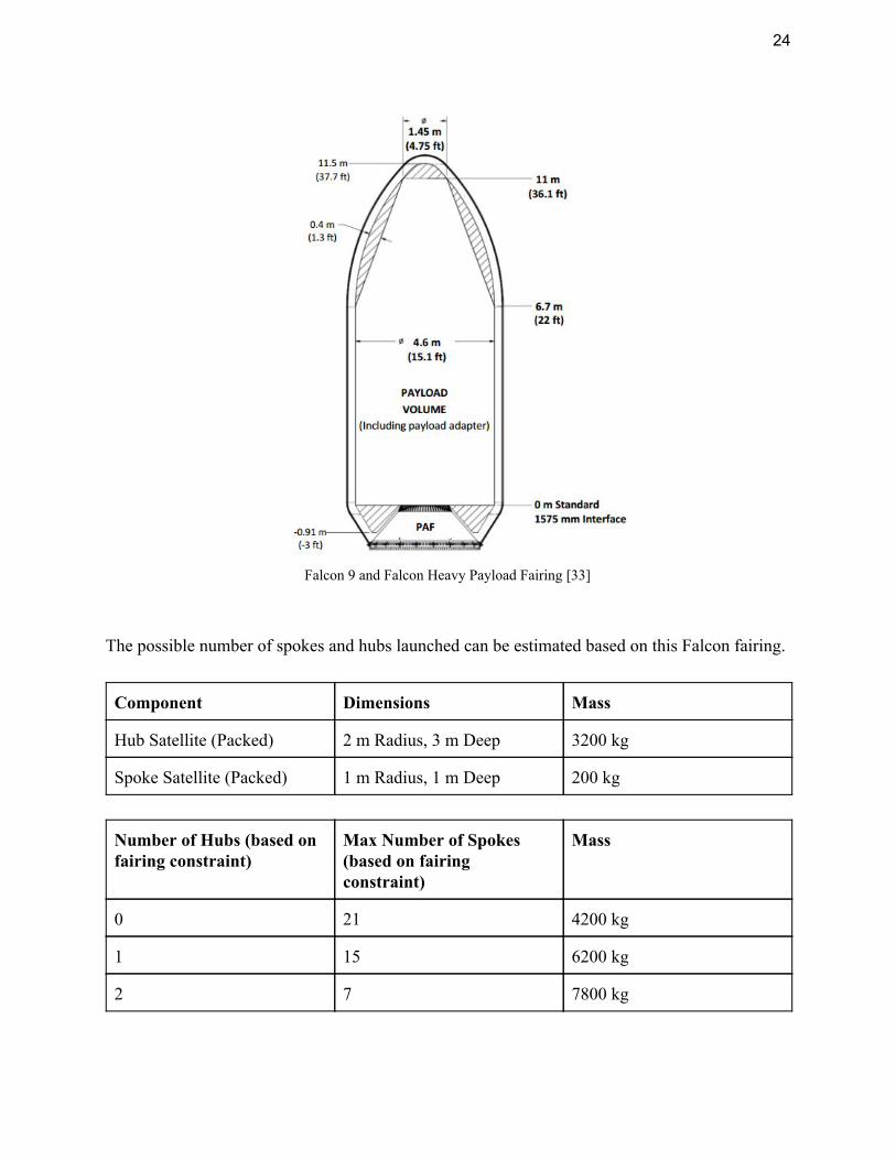
*First launch scheduled for early 2017, using projected performance numbers Our system will be launched using the SpaceX Falcon family of launch vehicles. This decision was based on their low cost, and our relatively straightforward launch requirements. There is no performance advantage of an Atlas V over a Falcon 9 or a Delta IV Heavy over the proposed Falcon Heavy that justifies the higher prices charged by ULA. Instead, these price differences are usually defended as a measure of the historical reliability of ULA launches. Based on the choice of launch vehicle and configuration, constraints are placed on both the mass and volume of our payload. Both the Falcon 9 and Falcon Heavy use the same payload fairing.
24
Falcon 9 and Falcon Heavy Payload Fairing [33]
The possible number of spokes and hubs launched can be estimated based on this Falcon fairing.
Component Dimensions Mass
Hub Satellite (Packed) 2 m Radius, 3 m Deep 3200 kg
Spoke Satellite (Packed) 1 m Radius, 1 m Deep 200 kg
Number of Hubs (based on fairing constraint)
Max Number of Spokes (based on fairing constraint)
Mass
0 21 4200 kg
1 15 6200 kg
2 7 7800 kg

25
As shown by these charts, the Falcon 9 cannot launch the base set of 1 hub and 15 spoke satellites in its reusable configuration. It has the overall capacity to do so, but would require the first stage to be disposed of rather than returned, and would come at an unpublished higher price. To avoid this higher price, the Falcon Heavy in its reusable configuration is the most logical choice for launching the base set of satellites. The maximum number of spokes that can be launched at once is 21, and this is a limitation of the fairing volume, not the mass. The mass of 21 spoke satellites is light enough to be launched on a reusable Falcon 9, and as such, this is the better choice for launching missions solely focused on adding spoke satellites to an existing hub. This plot analyzes six current or near-term launch vehicles and compares their peak performance in regards to LSPC with their cost. Note that this assumes each vehicle is launched with its maximum payload by mass, and that there are no limits in regards to fairing volume.

26
Cost Estimation To create a rough order of magnitude (ROM) estimate, in this analysis, unknown production costs will be replaced by a value that scales based on weight. This practice is consistent with the work of Apgar et al. [34]. Spoke Cost Estimation (Per Spacecraft)
Cost Factor (FY00$)
Mass Total Cost (FY00$)
Total Cost (FY16$)*
Mylar $3.95 per m2 50 kg - $7,750
Additional Components
$25,000 per kg 150 kg $3,750,000 $5,200,000
Sum - 200 kg - $5,207,750
*Assumes an inflation rate of ~2.1% per year Hub Cost Estimation
Cost Factor (FY00$)
Mass Total Cost (FY00$)
Total Cost (FY16$)*
Transmitter $10,000 per kg 2700 kg $27,000,000 $37,400,000
Additional Components
$50,000 per kg 500 kg $25,000,000 $34,700,000
Sum - 3200 kg $52,000,000 $72,100,000
*Assumes an inflation rate of ~2.1% per year
Overall System Cost
There will be two default missions as a part of our system: “Base Set” and “Spoke Satellite Addition”. Base Set places a new hub satellite into GEO along with 15 accompanying spokes. Due to the high mass of the hub satellite, a Falcon Heavy is required for launch. Spoke Satellite Addition however does not launch a hub, and instead launches 21 spoke satellites to the location of a hub already in GEO. This increases the area that can be reflected onto the hub.

27
Base Set (1 Hub, 15 Spoke) Cost Breakdown
Item Cost
1 Hub Satellite $72,100,000
15 Spoke Satellites $78,116,250
1 Reusable Falcon Heavy Launch $90,000,000
Sum $240,216,250
Spoke Satellite Addition Cost Breakdown
Item Cost
21 Spoke Satellites $109,362,750
1 Reusable Falcon 9 Launch $62,000,000
Sum $171,362,750
System Progression
Event Number of Hubs
Number of Spokes
Sum Cost Average Power Production
$/kW
Ground Infrastructure Install
0 0 $2,300,000 0 -
Base Set Launch
1 15 $242,516,250 9 MW $26,946.25
Spoke Satellite Addition Launch
1 36 $413,879,000 21.6 MW $19,161.06
This chart shows the team’s vision for how our system could progress through three sequential stages, and the savings that come with scalability. Note that this is a longer term vision, as the hub satellite is currently designed only to transmit 7-11 MW of power.

28
Learning Curve
One of the key features of our system is that it involves many relatively inexpensive spoke satellites as the reflection mechanism. While this was originally designed for scalability and ease of maintenance, it also comes with the added benefit of developing a learning curve as more of our spoke satellites are manufactured. All costs shown above are calculated for “theoretical first units,” (TFU) or the first unit to be produced. As more are manufactured however, factory performance will improve, and the cost of each individual unit will drop. In engineering economics, this is known as the learning curve.
ost of N units L FUC = * T
N L = (1− )ln(2)ln( )S
1
FU Theoretical first unit costT =
Number of units producedN = Learning curve slopeS =
Historically in aerospace design, the learning curve slope has been set at 0.95 if less than 10 units are produced, 0.9 if 10-50 units are produced, and 0.85 if more than 50 units are produced [34]. Given that there are 15 spoke satellites in each launch, our system will immediately reach a lift curve slope of 0.9, and will further lower it to 0.85 after 5 launches.

29
Political and Regulatory Issues There are many important regulatory and legal considerations to consider regarding large space-based solar power satellites. These systems are unprecedented in both their scale, and their intended function. The recent expansion of the commercial space industry has pushed the boundaries of our current space law frameworks, and such a system will only add to these stresses. The primary relevant regulatory body for satellites in geostationary orbit is the International Telecommunications Union (ITU). The ITU is a United Nations body that manages frequency spectrum usage and publishes locations of satellites in GEO. Signal interference between adjacent satellite systems could lead to a loss of data, or worse, a potential collision. Space-based solar power systems would bring challenges related to both their physical location and radio interference. Proposed designs for these systems have been very large compared to most modern satellites. Our system is designed to be scalable, but even at its base configuration would be much larger than typical GEO satellites. Orbital “slots” in GEO are already becoming somewhat crowded, and as more companies and countries have the ability to access space, this issue will continue to grow [35]. By the time solar satellites are ready for deployment, it is not a given that there will be large orbital slots available. Another unique regulatory challenge for space-based solar power comes from the fact that these systems must transmit power to Earth (using microwaves in our system). In the United States, the Federal Communications Commission (FCC) licenses all transmitters and many receivers, and must seek oversight from the ITU when transmissions are made across national borders. Our power transmission system would be subject to licensing and could encounter resistance due to the possibility of interfering with communication systems in lower orbits and within the atmosphere [36]. As microwaves are transmitted to the ground, they must pass through the National Airspace System (NAS), the layer between the ground and 60,000 feet. Currently, the Federal Aviation Administration (FAA) has the authority to regulate this airspace, including launch and reentry of spacecraft, but not on-orbit activities. However, given the potential for interference with aircraft avionics, it is possible that the FAA could push for their own oversight of the power transmission.

30
In addition to international and national regulations, space-based solar power systems could see challenges from some of the core tenets of space law. The Outer Space Treaty is the fundamental treaty of space law. Signed in 1967 and ratified by all major space powers, this treaty developed the framework for the peaceful and scientific use of space [37]. Of particular relevance to solar power systems is Article IV:
“States Parties to the Treaty undertake not to place in orbit around the Earth any objects carrying nuclear weapons or any other kinds of weapons of mass destruction, install such weapons on celestial bodies, or station such weapons in outer space in any other manner. …”
While the term “weapons of mass destruction” typically refers to nuclear, chemical, or biological weapons, no definition is provided here, and there is no accepted international definition elsewhere. Most power transmission subsystem designs, including our own, call for microwaves with a low enough intensity that they would be harmless to humans, but others have called for the use of high-intensity lasers to transmit power. It would be reasonable to believe that many would object to the use of high-intensity lasers directed towards Earth and could make the argument that they constituted “weapons of mass destruction”. This could be especially true if the satellite is developed by a government rather than as a commercial venture. Others have argued that these systems could potentially violate Article IX of the Outer Space Treaty:
“States Parties to the Treaty shall pursue studies of outer space, including the moon and other celestial bodies, and conduct exploration of them so as to avoid their harmful contamination and also adverse changes in the environment of the earth resulting from the introduction of extraterrestrial matter and, where necessary, shall adopt appropriate measures for this purpose.”
An argument could be made that potential communications interference due to microwave transmission through the atmosphere and medium and low earth orbit range could be classified as harmful contamination [36]. Political, regulatory, and legal issues are important to consider during the design of any system, even more so when you consider the unprecedented nature of space-based solar power systems. Our designed system could face significant pushback, particularly from those worried about bandwidth interference either in LEO, the NAS, or on the ground.

31
Conclusions and Recommendations The Lightweight Solar Power Constellation met some of the technical requirements and
reveals some of the problems with space based solar power. The cost per system requirement was not met because of the very high costs of manufacturing and launch. The mass per system requirement was not met because of the mass of the unexpectedly high mass of the microwave transmitter array on the hub satellite. The design was successful in the requirement of the number of launches per system as a single system can fit on one Falcon Heavy launch. The total output power requirement was not met as the efficiency ranges due to the constellation’s orientation changes through a given day. This is the same reason for the LSPC not meeting the requirement of total system efficiency. The design did not met the target of scalability as a 1GW version of this system is not economically feasible.
Technical Need Technical Requirement
Target Value Actual Values
Cost per System $/kW 20000 26,946.25
System Mass kg 3000 6200
Number of Launches per System
# 4 1
Total Output Power MW 10 7-11
Total System Efficiency
% 20 13.88-21.98
Scalability Range 10kW-1GW 500kW-135MW
The team took a realistic approach to the design of the LSPC. The design was created
based off the decision to see if a small scale version of space based solar power could be feasible with current technology. What the team has learned from the analysis of the space based solar power problem is that the costs associated with manufacturing and launching satellites as well as the loss of efficiency in solar cells and transmitting microwave power make a small scale system is not economically feasible today. The analysis also showed that the larger the system is the lower the $/kW ratio is. A GW system would have to be implemented to make space based solar power possible.
This method of space based solar power can only be recommended if solar panel and microwave transmission technology is improved. The largest drop in efficiency of the LSPC was

32
from the solar panels, even with the panels being at a relatively high efficiency. Although concentrated solar cell efficiency is approaching the physical limit of efficiency, improvements can be made in the cost of manufacturing and the overall mass of solar panels can be reduced. Microwave transmission was the other main issue with the LSPC. The microwave transmitter added 2700kg to the hub satellite alone. Massive improvements need to be made to the size and mass of microwave systems.
The team agrees with the conclusions of others who have analyzed space based solar power in that with current and near term technology a system such as the LSPC is not economically feasible. Massive improvements in technology need to occur. Large investments will be required to create space based solar power on any sort of scale relevant to meeting the world’s energy needs.

33
Bibliography
1. Brown, W.C., “The History of Power Transmission by Radio Waves,” IEEE Transactions on Microwave Theory and Techniques , published September 1984; Vol. MTT-32, NO. 9, 1984, pp. 1230-1242
2. Final Proc. Solar power Satellite Program Rev. DOE?NASA Satellite Power System Concept Develop. Evaluation Program , Conf.-800491, July 1980
3. Sangster, A.J., “Solar Power Satellites (SPS),” Electromagnetic Foundations of Solar Radiation Collection: A Technology for Sustainability , electronic, Springer International Publishing, Switzerland, 2014, pp. 207-240
4. “Mylar Product Information,” DuPont Teijin Films, 2003. 5. NASA, “Nodes - Network & Operations Demonstration Satellite,”, NASA [website], 2015
http://www.nasa.gov/centers/ames/engineering/projects/nodes.html [retrieved August 2016]
6. NASA, “Cubesat Proximity Operations Demonstration,” NASA [website], 2013, http://www.nasa.gov/directorates/spacetech/small_spacecraft/cpod_project.html [retrieved August 2016]
7. Philipps, S., Bett, A., Horowitz, K., Kurtz, S., “Current Status of Concentrator Photovoltaic (CPV) Technology,” Fraunhofer Institute for Solar Systems, National Renewable Energy Laboratory, February 2016.
8. Boeing, “Active Thermal Control System (ATCS) Overview,” The Boeing Company. 9. Mankins, J. C., “SPS-ALPHA: The First Practical Solar Power Satellite via Arbitrarily
Large Phased Array,” Artemis Innovation Management Solutions LLC, September 2012 10. Puig-Suari, J., “6U CubeSat Design Specification,” The CubeSat Program. 11. NASA, “James Webb Space Telescope Vital Statistics,” NASA [website], 2016,
http://jwst.nasa.gov/facts.html [retrieved August 2016] 12. Say, C., Duich, J., Huskamp, C., White, R., “Cost Effective Aluminum Beryllium Mirrors
for Critical Applications,” Material Technologies and Applications to Optics, Structures, Components, and Sub-Systems , SPIE, Vol. 8837, 2013.
13. California Institute of Technology, “The Primary Mirror,” Jet Propulsion Laboratory [website], 2005 https://pds.jpl.nasa.gov/planets/captions/hubble/hst01.htm [retrieved August 2016].
14. Lichodziejewski, D., Derbès, B., West, J., Reinert, R., Belvin, K., Pappa, R., “Bringing an Effective Solar Sail Design Toward TRL 6,” 39th Joint Propulsion Conference and Exhibit, AIAA/ASME/SAE/ASEE, Huntsville, Alabama, 2003.
15. “Mylar Polyester PET Film”. CSHyde [website], 2016 http://catalog.cshyde.com/viewitems/films/mylar-polyester-pet-film [retrieved August 2016].

34
16. Kurtz, S., “Opportunities and Challenges for Development of a Mature Concentrating Photovoltaic Power Industry,” National Renewable Energy Laboratory, November 2012.
17. White, A. K., “Liquid Droplet Radiator Development Status,” NASA TM-89852, July 1987.
18. Jones, D. R., “Space Solar Power Technical Plan, Concentrated Solar in Sun-synchronous Orbit,” Online Journal of Space Communication [online], Vol. 18, 2014, http://spacejournal.ohio.edu/issue18/powersat.html [retrieved August 2016]
19. Jones, R., “Alternative Orbits, A New Space Solar Power Reference Design,” Online Journal of Space Communication [online], Vol. 16, 2010, http://spacejournal.ohio.edu/issue16/jones.html [retrieved August 2016]
20. Orbital ATK, “Satellite Mission Extension Services,” Orbital ATK [website], 2016, http://www.orbitalatk.com/space-systems/human-space-advanced-systems/mission-extension-services/default.aspx [retrieved August 2016]
21. NASA Satellite Servicing Capabilities Office, “Robotic Refueling Mission,” Goddard Space Flight Center [website], 2016, https://ssco.gsfc.nasa.gov/robotic_refueling_mission.html [retrieved August 2016]
22. Kennedy, F., “Orbital Express Space Operations Architecture,” Defense Advanced Research Projects Agency [website], 2007, http://archive.darpa.mil/orbitalexpress/index.html [retrieved August 2016]
23. Sasaki, S., Tanaka, K., and Maki, K.I., “Microwave Power Transmission Technologies for Solar Power Satellites,” Proceedings of the IEEE , Vol. 101, No. 6, June 2013, pp. 1438-1447
24. Bergsrud, C., Noghanian, S., Straub, J., and Fevig, R., “Orbit-to-Ground Wireless Power Transfer Test Mission,” IEEE Aerospace Conference Proceedings , IEEE, March 2013, doi: 10.1109/AERO.2013.6497314
25. Kaya, N., Matsumoto, H., Miyatake, S., and Obayashi, T., “Nonlinear Interaction of Strong Microwave Beam With the Ionosphere MINIX Rocket Experiment,” Space Power , Vol. 6:3, January 1986
26. Kaya, N., Kojima, H., Matsumoto, H., and Akiba, R., “ISY-METS Rocket Experiment for Microwave Energy Transmission,” Acta Astronautica , Vol. 34, October 1994, pp. 43-46, doi: 10.1016/0094-5765(94)90241-0
27. Mescia, L. and Massaro, A., “New Trends in Energy Harvesting from Earth Long-Wave Infrared Emission,” Advances in Materials Science and Engineering 2014 , published August 2014. doi: 10.1155/2014/252879
28. “Updated Capital Cost Estimates for Utility Scale Electricity Plants”, US Department of Energy [website], April 2013, http://www.eia.gov/forecasts/capitalcost/pdf/updated_capcost.pdf [retrieved August 2016]

35
29. SpaceX, “Capabilities and Services,” SpaceX [website], 2016, http://www.spacex.com/about/capabilities [retrieved August 2016]
30. United Launch Alliance, “Delta IV,” United Launch Alliance [website], 2016, http://www.ulalaunch.com/products_deltaiv.aspx [retrieved August 2016]
31. United Launch Alliance, “Frequently Asked Questions- Launch Costs,” United Launch Alliance [website], 2016, http://www.ulalaunch.com/faqs-launch-costs.aspx [retrieved August 2016]
32. United Launch Alliance, “Atlas V,” United Launch Alliance [website], 2016, http://www.ulalaunch.com/products_atlasv.aspx [retrieved August 2016]
33. SpaceX, “Falcon 9 Launch Vehicle Payload User’s Guide,” SpaceX, October 2015. 34. Apgar, H., Bearden, D., Wong, R., “Cost Modeling,” Space Mission Analysis and
Design , 3rd ed., Microcosm Press, El Segundo, CA, 1999, pp. 783-820. 35. Wallach, M. I., “Legal Issues for Space Based Solar Power,” Online Journal of Space
Communication [online], Vol. 16, 2010, http://spacejournal.ohio.edu/issue16/wallach.html [retrieved August 2016]
36. Bergsrud, C., Noghanian, S., Straub, J., Whalen, D., Fevig, R., “Orbit-to-Ground Wireless Power Transfer Test Mission,” 2013 Aerospace Conference , IEEE, Big Sky, MT, March 2013
37. Betancourt, K., “Legal Challenges Facing Solar Power Satellites,” Online Journal of Space Communication [online], Vol. 16, 2010, http://spacejournal.ohio.edu/issue16/betancourt.html [retrieved August 2016]
38. NOAA, “Daily Solar Irradiance”, National Oceanic and Atmospheric Administration [website], 1994, https://www.ngdc.noaa.gov/stp/solar/irrad.html [retrieved August 2016].

36
Appendix Efficiency Table
Segment Efficiency Power (W/m^2) Notes
Sunlight 100% 1367 [38] Flat panel power in Space
Amount of Sunlight 95% 1298.65 Amount of sunlight per day in GEO
Mirror Absorbance 84.64% 1099.18
Constellation Configuration
60%-95% 659.51-1044.22 Time of day at location changes amount of incident sunlight
Concentrated Photovoltaic to DC
35%-50% 230.83-522.11 Record is currently 46% at 500 suns. Projected efficiency is 50%
Power management and Distribution
99% 228.51-516.89
DC to Microwave 85% 194.24-439.35
Atmospheric Beaming 90% 174.81-395.42
Microwave to DC 70% - 80% 122.37-316.34
DC to AC 95% 116.25-300.52 Electricity on power grid
Total Efficiency 8.50% - 21.98% 176.25-300.52
LSPC Scaling
Power Effective Area Required (m^2) # of 25m Spoke Satellites
1kW 3.750 1
1MW 3750 2
1GW 3750000 2000
Effective area = Power/(Total Efficiency of best system at worst configuration*Irradiance) Radius = ((effective area/worst configuration efficiency(60%))/pi)^(1/2)