LIGHTLY REINFORCED AND PRECAST CONCRETE WALLS: …the seismic design of RC walls (CERC 2012). As...
10
LIGHTLY REINFORCED AND PRECAST CONCRETE WALLS: RECENT RESEARCH AND DESIGN RECOMMENDATIONS RICHARD HENRY, YIQIU LU, POUYA SEIFI, TONGYUE ZHANG, LUCAS HOGAN, JASON INGHAM, KEN ELWOOD Department of Civil and Environmental Engineering, University of Auckland ABSTRACT The Canterbury Earthquake Royal Commission made a number of recommendations that led to research related to the seismic behaviour and design of lightly reinforced and precast concrete walls. The key objectives of this research project include verification of minimum vertical reinforcement requirements for new reinforced concrete (RC) walls, development of assessment guidelines for existing lightly reinforced walls, and development of appropriate detailing for precast concrete panel connections. Large-scale wall tests highlighted that RC walls designed according to current vertical reinforcement limits in NZS 3101:2006 were susceptible to a concentration of inelastic deformation at a small number of flexural cracks. Additional tests confirmed that a small amount of additional vertical reinforcement at the ends of the walls could significantly improve the crack distribution and ductility. These experimental tests and additional numerical models were used to verify the changes to the minimum vertical reinforcement requirements for RC walls proposed in NZS 3101:2006 (Amendment 3). A separate series of wall tests has investigated the seismic behaviour of precast panel connections. The results of tests with grouted metal duct connections confirmed that walls with existing detailing performed adequately when carrying low axial loads, but performance was found to reduce as the axial load and wall length increased. The use of transverse confinement reinforcement around the grouted metal ducts was observed to prevent a brittle connection response and improved the robustness of the reinforcement splice when subjected to large lateral drifts. INTRODUCTION The 2010/2011 Canterbury earthquake series in New Zealand tested the built infrastructure to beyond the design level seismic loading and caused significant damage to both older and modern reinforced concrete buildings (Kam et al. 2011). In particular, severe damage was observed to reinforced concrete (RC) walls in several modern multi-storey buildings (Sritharan et al. 2014). Undesirable failure modes that were observed included a lack of distributed flexural cracks, premature fracture of vertical reinforcement, global and local wall buckling, bar buckling, and shear failure, in addition to evidence of poor detailing. The Canterbury Earthquakes Royal Commission (CERC) highlighted the need for further research to improve the seismic design of RC walls (CERC 2012). As part of a wider programme to address the CERC recommendations for RC buildings, research is being conducted into lightly reinforced walls in multi-storey buildings and connections in lightly reinforced precast concrete wall panels. The key objectives of this research project include verification of minimum vertical
Transcript of LIGHTLY REINFORCED AND PRECAST CONCRETE WALLS: …the seismic design of RC walls (CERC 2012). As...

LIGHTLY REINFORCED AND PRECAST CONCRETE WALLS: RECENT RESEARCH AND DESIGN RECOMMENDATIONS
RICHARD HENRY, YIQIU LU, POUYA SEIFI, TONGYUE ZHANG, LUCAS HOGAN, JASON INGHAM, KEN ELWOOD
Department of Civil and Environmental Engineering, University of Auckland ABSTRACT The Canterbury Earthquake Royal Commission made a number of recommendations that led to research related to the seismic behaviour and design of lightly reinforced and precast concrete walls. The key objectives of this research project include verification of minimum vertical reinforcement requirements for new reinforced concrete (RC) walls, development of assessment guidelines for existing lightly reinforced walls, and development of appropriate detailing for precast concrete panel connections. Large-scale wall tests highlighted that RC walls designed according to current vertical reinforcement limits in NZS 3101:2006 were susceptible to a concentration of inelastic deformation at a small number of flexural cracks. Additional tests confirmed that a small amount of additional vertical reinforcement at the ends of the walls could significantly improve the crack distribution and ductility. These experimental tests and additional numerical models were used to verify the changes to the minimum vertical reinforcement requirements for RC walls proposed in NZS 3101:2006 (Amendment 3). A separate series of wall tests has investigated the seismic behaviour of precast panel connections. The results of tests with grouted metal duct connections confirmed that walls with existing detailing performed adequately when carrying low axial loads, but performance was found to reduce as the axial load and wall length increased. The use of transverse confinement reinforcement around the grouted metal ducts was observed to prevent a brittle connection response and improved the robustness of the reinforcement splice when subjected to large lateral drifts. INTRODUCTION The 2010/2011 Canterbury earthquake series in New Zealand tested the built infrastructure to beyond the design level seismic loading and caused significant damage to both older and modern reinforced concrete buildings (Kam et al. 2011). In particular, severe damage was observed to reinforced concrete (RC) walls in several modern multi-storey buildings (Sritharan et al. 2014). Undesirable failure modes that were observed included a lack of distributed flexural cracks, premature fracture of vertical reinforcement, global and local wall buckling, bar buckling, and shear failure, in addition to evidence of poor detailing. The Canterbury Earthquakes Royal Commission (CERC) highlighted the need for further research to improve the seismic design of RC walls (CERC 2012). As part of a wider programme to address the CERC recommendations for RC buildings, research is being conducted into lightly reinforced walls in multi-storey buildings and connections in lightly reinforced precast concrete wall panels. The key objectives of this research project include verification of minimum vertical

reinforcement requirements for new RC walls, development of assessment guidelines for existing lightly reinforced walls, and development of appropriate detailing for precast concrete panel connections. A combination of experimental testing and numerical modelling has been used to investigate the seismic behaviour of these types of walls and is summarised here with reference to the key output and recommendations to date. MINIMUM VERTICAL REINFORCEMENT Assessments of buildings following the Canterbury earthquakes highlighted several examples of RC walls in multi-storey buildings that had formed a limited number of cracks in the plastic hinge region as opposed to the expected larger number of distributed cracks (Kam et al. 2011, Sritharan et al. 2014). After breaking out the surrounding concrete in one wall it was found that the vertical reinforcing steel was fractured due to the inelastic strain demand at the crack location. If too little vertical reinforcement is used in walls, there is insufficient tension generated to replace the tensile resistance provided by the surrounding concrete after a crack forms, resulting in a reduced number of cracks in the critical moment region, large crack widths, and possible fracture of the reinforcing steel during earthquakes. The Canterbury Earthquake Royal Commission recommended that research be conducted to refine design requirements for crack control in RC walls (CERC 2012). Historically, minimum requirements for vertical reinforcement in RC walls were governed by shrinkage and temperature effects. More recently, minimum vertical reinforcement limits for RC walls have been increased in design standards worldwide to ensure that ductile behaviour is achieved when yielding of reinforcement is expected. In the 2006 revision of the New Zealand Concrete Structures Standard, NZS 3101:2006, the minimum required vertical reinforcement in RC walls was increased by over 80% with the adoption of a similar equation to that previously used for RC beams. Because of these recent changes, some of the RC walls in Christchurch that were observed to have only a few flexural cracks and fractured vertical reinforcement had vertical reinforcement contents below the current limit in NZS 3101:2006. Additionally, higher than expected concrete strengths may have contributed to the lack of flexural cracks in some lightly reinforced RC walls in Christchurch (CERC 2012). Moment-curvature analysis was used to provide an initial assessment of the current vertical reinforcement limits for RC walls (Henry 2013). From this analysis it was found that even when the concrete strengths are known, the current minimum vertical reinforcement limits for RC walls in NZS 3101:2006 (A2) may not be appropriate as the margin of separation between cracking and nominal strength would be less than for an equivalent beam unless a significant axial load is applied. Finite Element Modelling A series of numerical analyses were conducted to investigate the lateral load response of RC walls with minimum reinforcement using nonlinear finite element program VecTor2 (Wong & Vecchio 2003). The development of the VecTor2 wall models is described in more detail by Lu et al. (2015a, 2015b). The grid-F wall from the Gallery Apartments building in Christchurch was used as the baseline for the analyses. The grid-F wall had a length of 4300 mm, a thickness of 325 mm with a vertical reinforcement ratio of 0.16%, less than the 0.27% currently required by NZS 3101:2006 (A2). The behaviour of the modelled as-built grid-F wall was similar to the failure mode observed during the 22 Feb 2011 Christchurch earthquake, as shown in Figure 1a and b. A single flexural crack was observed at the wall base with the strain in the vertical reinforcement concentrated at the crack and not distributed along a large length of the bar. Because of the reduced spread of the plasticity, the wall demonstrated only limited ductility with fracture of vertical reinforcement occurring at only 0.75% lateral drift.

(a) Crack in grid-F wall (b) As-built grid-F (c) NZS 3101 (A2) (d) Additional reo at ends
Figure 1. Grid-F wall damage compared with crack patterns from different wall models
Additional analyses were conducted using the dimensions of the grid-F wall with modified reinforcement detailing in accordance with the current minimum requirements from different concrete standards worldwide (Lu et al. 2015b). The behaviour of the grid-F wall with a distributed vertical reinforcement ratio of 0.274% in accordance with minimum requirements of the amendment 2 version of NZS 3101:2006 (A2) is shown in Figure 1c. A total of four primary flexural cracks were observed, but still insufficient reinforcement to generate well distributed secondary cracks. A third analysis was conducted with increased vertical reinforcement at the ends of the wall (0.5% reinforcement ratio), as shown in Figure 1d. A significant improvement over the as-built and NZS 3101 wall was observed with the concentrated reinforcement in the end regions of the wall sufficient to generate a large number of secondary cracks in the plastic hinge region. Based on the preliminary numerical modelling results, it was suggested that RC walls designed prior to the introduction of stricter minimum reinforcement limits in NZS 3101:2006 (A2) are highly susceptible to a non-ductile failure characterised by a single crack. Walls with distributed vertical reinforcement in accordance with NZS 3101:2006 (A2) may exhibit some ductility, but that adding additional reinforcement at the wall ends can significantly improve the crack distribution and ductility in the plastic hinge region. Experimental tests A series of experimental tests was conducted to further investigate the existing minimum vertical reinforcement limits in NZS 3101:2006 (A2) and to verify the amendments proposed in NZS 3101:2006 (A3-draft) (Lu et al. 2015a, 2015b). A total of 10 1.4 m long, 2.8 m high and 150 mm thick RC walls were subjected to pseudo-static cyclic loading. The first 6 test walls (C1-6) were designed with distributed vertical reinforcement in accordance with minimum requirements in NZS 3101:2006 (A2) and the later 4 test walls (M1-4) were designed with additional vertical reinforcement at the ends of the wall in accordance with the proposed amendments to minimum reinforcement for ductile walls in NZS 3101:2006 (A3-draft), as described by Russell et al. (2015). The test variables are summarised in Table 1 and the drawings of the 10 test walls are shown in Figure 2. The walls were subjected to different loading configurations including three shear span ratios (2, 4, and 6) and axial load ranging from 0-6.6% of the wall axial capacity. Because of height limitations in the structural test hall, a test setup was designed to simulate the expected seismic loading on the bottom two storeys of a 40-50% scaled wall from a multi-storey building. An actuator was attached between the steel loading beam and the strong wall to apply horizontal loads to the wall, and two additional actuators were attached vertically at each end of the wall to achieve the required moment and axial load at the top of the wall.
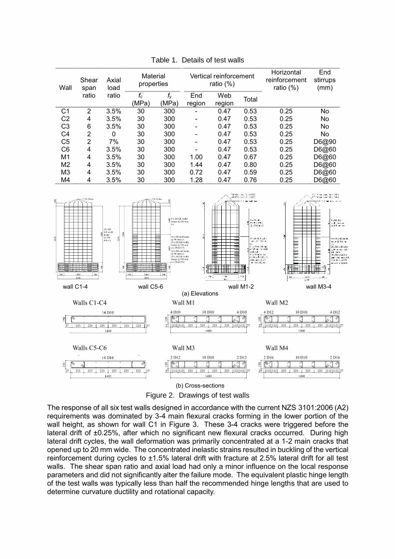
Table 1. Details of test walls
Wall Shear span ratio
Axial load ratio
Material properties
Vertical reinforcement ratio (%)
Horizontal reinforcement
ratio (%)
End stirrups (mm)
fc’ (MPa)
fy (MPa)
End region
Web region
Total
C1 2 3.5% 30 300 - 0.47 0.53 0.25 No C2 4 3.5% 30 300 - 0.47 0.53 0.25 No C3 6 3.5% 30 300 - 0.47 0.53 0.25 No C4 2 0 30 300 - 0.47 0.53 0.25 No C5 2 7% 30 300 - 0.47 0.53 0.25 D6@90 C6 4 3.5% 30 300 - 0.47 0.53 0.25 D6@60 M1 4 3.5% 30 300 1.00 0.47 0.67 0.25 D6@60 M2 4 3.5% 30 300 1.44 0.47 0.80 0.25 D6@60 M3 4 3.5% 30 300 0.72 0.47 0.59 0.25 D6@60 M4 4 3.5% 30 300 1.28 0.47 0.76 0.25 D6@60
wall C1-4 wall C5-6 wall M1-2 wall M3-4
(a) Elevations
Walls C1-C4
Walls C5-C6
(b) Cross-sections
Figure 2. Drawings of test walls
The response of all six test walls designed in accordance with the current NZS 3101:2006 (A2) requirements was dominated by 3-4 main flexural cracks forming in the lower portion of the wall height, as shown for wall C1 in Figure 3. These 3-4 cracks were triggered before the lateral drift of ±0.25%, after which no significant new flexural cracks occurred. During high lateral drift cycles, the wall deformation was primarily concentrated at a 1-2 main cracks that opened up to 20 mm wide. The concentrated inelastic strains resulted in buckling of the vertical reinforcement during cycles to ±1.5% lateral drift with fracture at 2.5% lateral drift for all test walls. The shear span ratio and axial load had only a minor influence on the local response parameters and did not significantly alter the failure mode. The equivalent plastic hinge length of the test walls was typically less than half the recommended hinge lengths that are used to determine curvature ductility and rotational capacity.

(b) Extent of flexural cracking
(a) Overall condition at 2.5% drift (c) Concrete crushing and bar buckling at east end
Figure 3. Photos of wall C1 at the end of testing
The test walls designed with additional vertical reinforcement in the ends of the wall, in accordance with the proposed amendments in NZS 3101:2006 (A3-draft), had significantly more distributed cracking than compared to the earlier test walls, as shown for wall M1 in Figure 4. The additional vertical reinforcement ensured that secondary cracks formed, and as a result the reinforcement strains and curvatures were more evenly distributed over the plastic hinge length. Vertical reinforcement contents higher than that proposed in the amendment did not significantly improve the cracking behaviour, but the use of larger diameter bars helped to delay the onset of reinforcement buckling. All of the walls satisfied the transverse reinforcement requirements in NZS 3101:2006 for a ductile hinge region, with spacing of 6db for wall M1 and reduced to 5db and 3.75db for walls M2 and M4 respectively.
(a) Overall condition at end of test
(b) crack pattern at 2.5% drift
Figure 4. Photo and crack pattern for test wall M1
Based on these experimental results, and supporting numerical analyses, the following recommendations were made:
The current minimum vertical reinforcement requirements for RC walls in NZS 3101:2006 (A2) are sufficient to prevent a sudden loss in strength after first

cracking, however, they are insufficient to ensure that a large number of secondary cracks form in plastic hinge regions. Additionally, the concentration of inelastic strains in lightly RC walls makes the vertical reinforcement highly vulnerable to buckling at modest lateral drifts.
The proposed increase in vertical reinforcement to √f′c/2fy in the end region of walls with limited ductile or ductile plastic hinge regions is sufficient to ensure that well distributed secondary cracks would form when considering expected concrete tensile strengths.
PRECAST WALL CONNECTIONS Precast concrete construction is common in New Zealand and walls in both low-rise and multi-storey buildings are typically constructed from precast panels. A review of manufactured precast concrete panels was undertaken in order to develop a comprehensive understanding of the common typologies for connections between precast concrete panels and foundations (Seifi et al. 2016). The database confirmed that buildings in regions of low or moderate seismicity are commonly constructed from thin precast concrete panels (150 mm) with only a single layer of minimum required horizontal and vertical reinforcement. In addition to the the aforementioned issues with lightly reinforced walls, the seismic behaviour of such wall precast panels is highly dependent on the connections. Examples of three commonly used wall-to-foundation connection details are shown in Figure 5.
(a) Threaded inserts (b) Metal duct (c) Grout sleeve
Figure 5. Cross sections of typical wall-to-foundation connections
Dowel connections The out-of-plane response of wall-to-foundation connections that used threaded inserts to connect the starter reinforcement (Figure 5a) was questioned following the Canterbury earthquakes due to the shallow embedment of the inserts and lack of robustness to cyclic loading. A series of 12 panel tests were completed to investigate both the monotonic and cyclic response of typically constructed threaded insert connection designs (Burley et al. 2014). As shown in Figure 6, the test panels did not perform well with the flexural cracks in the panel propagating vertically into the joint region behind the back of the inserts and the connection started acting like a pin. In many cases the panel did not reach its full flexural capacity prior to the onset of this failure mode. The tests highlighted the vulnerability of the connection with the inserts not embedded deep enough in the panel to intersect the compression region, as shown by the strut-and-tie model in Figure 6c. Additional tests were conducted to investigate alternative connection details that would allow the panel to develop its full flexural capacity without joint failure (Burridge et al. 2015). While some of these connection details proved successful, additional tests are ongoing to verify the behaviour when subjected to a combination of in-plane and out-of-plane loading, as would occur during an earthquake.

(a) Panels setup for testing
(b) Connection failure
(c) Strut and tie model
Figure 6. Out-of-plane tests of threaded insert connections
Grouted connections In multi-storey panels it is common to use grouted connections to splice vertical reinforcement. As shown in Figure 5b and 5c, grouted connections can use either a metal duct cast into the panel or a proprietary grout sleeve reinforcement coupler. An experimental programme was developed to assess the seismic behaviour of precast concrete panels connected to the foundation using grouted connections. The test program is currently in progress and initial results were reported by Seifi et al. (2015). The summary of the key parameters of 5 of the test walls is provided in Table 2 and examples of the wall details are shown in Figure 7. The test walls were either 1000 × 3000 × 150 mm or 2000 × 4000 × 150 mm, with HD12 vertical reinforcement at 225 mm c/c, and HD16 connection reinforcement at either 400 mm or 450 mm spacing. The connection bars protruded from the foundation and were embedded inside the wall in 600 mm long corrugated metal ducts that were filled with grout. The walls were tested in-plane using a horizontal actuator providing lateral loading to the top of the wall.
Table 2. Grouted connection test walls
Test wall
Length (mm)
Height (mm)
Aspect ratio
Thickness (mm)
Connection reinforcement
Vertical reinforcement
Stirrups Axial Load
(%Agf’c)
1 1000 3000 3 150 HD16@400 Single layer HD12@225
- 0
2 1000 3000 3 200 HD16@400 Double layer HD12@225
- 0
3 1000 3000 3 150 HD16@400 Single layer HD12@225
- 5%
4 2000 4000 2 150 HD16@450 Single layer HD12@225
- 5%
5 2000 4000 2 150 HD16@450 Single layer HD12@225
Yes 5%
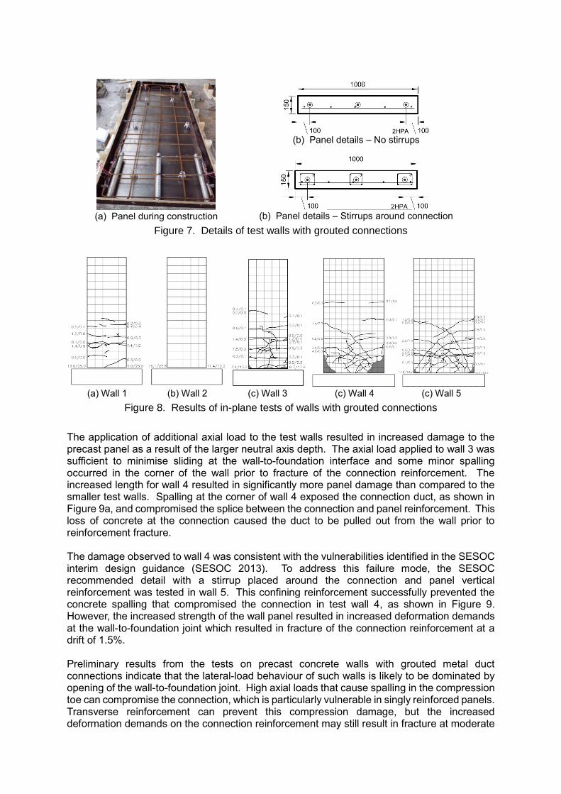
The crack patterns from the 5 tested walls with grouted metal duct connections are shown in Figure 8. The behaviour of the test walls was characterised by the opening of the joint at the wall-to-foundation interface, with the connection flexural capacity slightly less than that of the panel. The widest crack in the panel occurred at a height of 600 mm where the connection reinforcement was terminated. For the walls with no axial load applied (1 & 2), no significant damage occurred to the panel and elongation of connection bars resulted in sliding at the wall-to-foundation joint during large drift cycles. The tests were continued until the rupture of the connection reinforcement. The increase strength of the doubly reinforced wall 2 resulted in no flexural cracks in the wall panel, with deformation concentrated at the wall-to-panel joint.
(a) Panel during construction
(b) Panel details – No stirrups
(b) Panel details – Stirrups around connection
Figure 7. Details of test walls with grouted connections
(a) Wall 1 (b) Wall 2 (c) Wall 3 (c) Wall 4 (c) Wall 5
Figure 8. Results of in-plane tests of walls with grouted connections
The application of additional axial load to the test walls resulted in increased damage to the precast panel as a result of the larger neutral axis depth. The axial load applied to wall 3 was sufficient to minimise sliding at the wall-to-foundation interface and some minor spalling occurred in the corner of the wall prior to fracture of the connection reinforcement. The increased length for wall 4 resulted in significantly more panel damage than compared to the smaller test walls. Spalling at the corner of wall 4 exposed the connection duct, as shown in Figure 9a, and compromised the splice between the connection and panel reinforcement. This loss of concrete at the connection caused the duct to be pulled out from the wall prior to reinforcement fracture. The damage observed to wall 4 was consistent with the vulnerabilities identified in the SESOC interim design guidance (SESOC 2013). To address this failure mode, the SESOC recommended detail with a stirrup placed around the connection and panel vertical reinforcement was tested in wall 5. This confining reinforcement successfully prevented the concrete spalling that compromised the connection in test wall 4, as shown in Figure 9. However, the increased strength of the wall panel resulted in increased deformation demands at the wall-to-foundation joint which resulted in fracture of the connection reinforcement at a drift of 1.5%. Preliminary results from the tests on precast concrete walls with grouted metal duct connections indicate that the lateral-load behaviour of such walls is likely to be dominated by opening of the wall-to-foundation joint. High axial loads that cause spalling in the compression toe can compromise the connection, which is particularly vulnerable in singly reinforced panels. Transverse reinforcement can prevent this compression damage, but the increased deformation demands on the connection reinforcement may still result in fracture at moderate

drifts unless the reinforcement is debonded over the connection region. Additional tests are in progress to understand the connection behaviour in more detail and to verify the wall behaviour when subjected to both in-plane and out-of-plane lateral deformations.
(a) Panel 4 (b) Panel 5
Figure 9. Condition of the ends of panels 4 and 5 at the conclusion of testing
SUMMARY A combination of numerical modelling and laboratory tests were conducted to investigate the seismic behaviour of lightly reinforced concrete walls. The numerical modelling confirmed the observed behaviour of an RC wall building in Christchurch that exhibited a single flexural crack. The results of large-scale walls indicated that the current minimum distributed vertical reinforcement limits in NZS 3101:2006 are not sufficient to prevent the concentration of inelastic deformation at a small number of flexural cracks and are only suitable for walls with low ductility demands. The proposed increased vertical reinforcement at the ends of walls with limited ductile of ductile plastic hinges are sufficient to ensure that well distributed secondary crack form with a good spread of plasticity. Additional wall tests have been conducted to investigate the seismic behaviour of panel-to-foundation connections in singly reinforced precast concrete panels. Out-of-plane tests of panels with dowel connections that use threaded inserts highlighted the lack of robustness of these shallow embedded insets. Furthermore, in-plane tests of walls with grouted connections confirmed that the panel response is dominated by the connection. Spalling of the compression toe can compromise the connection and transverse reinforcement can be used to prevent such failures. Research into these topics is ongoing and additional recommendations and design guidance is expected following the completion of the current projects in 2017. ACKNOWLEDGMENTS The authors would like to acknowledge the funding provided by the Building Performance Branch of the Ministry of Business, Employment and Innovation (MBIE), the Natural Hazards Research Platform, and China Scholarship Council (CSC), in addition to project support and management provided by the UC Quake Center. Advice and donated products and services

provided by Precast New Zealand (PCNZ), Wilco Precast, Concretec, and Reid-ITW Construction Systems ANZ is greatly appreciated. REFERENCES
Burley, J., Faitotoa, T., Seifi, P., Henry, R. S., Ingham, J. M. (2014). Out-of-plane behaviour of connections between precast concrete panels and their foundations. Proceedings of the New Zealand Concrete Industry Conference, Wairakei, New Zealand, October 9-11.
Burridge, S., Casey, M., Raby, M., Wright, H., Hogan, L., Henry, R. S., Ingham, J. M. (2015) Improved detailing of precast concrete panel to foundation connections to withstand out-of-plane earthquake loads. Proceedings of the 2015 New Zealand Concrete Industry Conference, Rotorua, New Zealand, October 8-10.
Canterbury Earthquakes Royal Commission (CERC). (2012). Final report: Volume 2: The performance of Christchurch CBD buildings. http://canterbury.royalcommission.govt.nz/Commission-Reports, Wellington, New Zealand.
Henry, R. S. (2013). Assessment of minimum vertical reinforcement limits for RC walls. Bulletin of the New Zealand Society for Earthquake Engineering, 46(2), 88-96.
Kam, W. Y., Pampanin, S., Elwood, K. J. (2011). Seismic performance of reinforced concrete buildings in the 22 February Christchurch (Lyttelton) earthquake. Bulletin of the New Zealand Society for Earthquake Engineering, 44(4), 239-278.
Lu, Y., Henry, R. S., Gultom, R., Ma, Q. T. (2015a). Experimental testing and modelling of reinforced concrete walls with minimum vertical reinforcement. Proceedings of the 2015 NZSEE Annual Conference, Rotorua, April 10-12.
Lu, Y., Henry, R. S. (2015b). Seismic behaviour of reinforced concrete walls with minimum vertical reinforcement. Proceedings of the fib Symposium, Copenhagen, Denmark, May 18-20.
NZS 3101:2006. Concrete Structures Standard. Wellington, New Zealand, Standards New Zealand.
Russell, A., Henry, R. S., Fenwick, R. C. (2015). Design of RC walls post the Canterbury earthquakes. Proceedings of the Concrete Industries Conference, Rotorua, Oct 8-10.
SESOC (2013). Interim Design Guidance: Design of conventional structural systems following the Canterbury earthquakes. Version No.9, Structural Engineering Society of New Zealand, New Zealand.
Seifi, P., Henry, R. S., Ingham, J. M. (2015). Panel connection details in existing New Zealand precast concrete buildings. Bulletin of the New Zealand Society for Earthquake Engineering, 49(2), 190-199.
Smith, P. and England, V. (2012). Independent assessment on earthquake performance of Gallery Apartments - 62 Gloucester Street. http://canterbury.royalcommission.govt.nz/documents-by-key/20120217.3188, Report prepared for the Canterbury Earthquakes Royal Commission.
Sritharan, S., Beyer, K., Henry, R. S., Chai, Y. H. Kowalsky, M., Bull, D. (2014). Understanding poor seismic performance of concrete walls and design implications. Earthquake Spectra, 30(1), 307-334.
Wong, S. M. and Vecchio, F. J. (2003). VecTor2 and formworks user's manual. Toronto (Canada), University of Toronto.