LightCycler Probe Design Software 2...4 LightCycler Probe Design Software 2.0 General Comments Thank...
96
Built on Experience… …Designed for the Future Roche Applied Science LightCycler Probe Design Software 2.0 Version 1.0 February 2004 Cat.No. 04 342 054 001
Transcript of LightCycler Probe Design Software 2...4 LightCycler Probe Design Software 2.0 General Comments Thank...

Built on Experience… …Designed for the Future
Roche Applied Science
LightCyclerProbe Design Software 2.0
Version 1.0February 2004Cat.No. 04 342 054 001

1General Comments
Roche Applied Science
LightCycler Probe DesignSoftware 2.0
Version 1.0February 2004
Cat.-No. 04 342 054 001

LightCycler Probe Design Software 2.02
I. Features of the LightCycler Probe Design Software 2.0 .............................................................. 4
II. About this manual ............................................................................................................................................. 5
III. Symbols used in this manual ...................................................................................................................... 5
1. Installing and starting the software ........................................................................................................ 91.1 Hardware and software requirements ........................................................................................................... 91.2 Installing the new software version ............................................................................................................. 10
2. Overview of windows and menus .......................................................................................................... 132.1 Design tab ............................................................................................................................................................. 142.2 Sequence tab ....................................................................................................................................................... 14
2.2.1 Edit buttons .................................................................................................................................................... 142.2.2 Design parameters ...................................................................................................................................... 15
2.3 Analysis tab .......................................................................................................................................................... 172.4 Primer Probe Sets tab ....................................................................................................................................... 182.5 Menus ..................................................................................................................................................................... 19
2.5.1 File menu ....................................................................................................................................................... 192.5.2 Sequence menu .......................................................................................................................................... 202.5.3 Settings menu .............................................................................................................................................. 212.5.4 Tools menu .................................................................................................................................................... 222.5.5 Help menu ..................................................................................................................................................... 22
1. How primers and probes work in quantification reactions ..................................................... 251.1 HybProbe Probes for quantification ............................................................................................................ 26
1.1.1 HybProbe Probes ........................................................................................................................................ 261.2 The role of primers used with SYBR Green I dye ................................................................................... 28
2. How primers and probes work in mutation detection reactions ......................................... 282.1 Mutation detection formats ............................................................................................................................ 29
2.1.1 SimpleProbe .................................................................................................................................................. 292.1.2 HybProbe ........................................................................................................................................................ 292.1.3 HybProbe Plus .............................................................................................................................................. 31
3. General requirements of good primer and probe design ......................................................... 323.1 Avoid inter- or intra-molecular homologies ............................................................................................. 323.2 Avoid negative sequence motifs ................................................................................................................... 333.3 Appropriate melting temperature ................................................................................................................ 343.4 Single annealing site ......................................................................................................................................... 343.5 Other restrictions ................................................................................................................................................ 35
4. Additional requirements for designing mutation-detection probes .................................. 35
General Comments Page
A Software Setup Page
B Principles of Primers and Probe Design Page
Table of Content

3General Comments
1 Providing a DNA sequence ....................................................................................................................... 39
2. Specifying reaction conditions ............................................................................................................... 43
3. Specifying design parameters ................................................................................................................ 443.1 Choosing the experiment and probe type ................................................................................................ 443.2 Specifying sequence information for quantification probes or primers only .............................. 453.3 Specifying sequence information for mutation detection probes .................................................... 473.4 Specifying experiment settings ..................................................................................................................... 50
4. Analyzing and selecting the design region ...................................................................................... 52
5. Viewing and saving results ....................................................................................................................... 545.1 How scores are displayed on the Primer Probe Sets tab .................................................................... 565.2 Viewing primers and probes within the sequence fragment ............................................................. 57
6. Exporting a design as an XML file ......................................................................................................... 57
7. Using existing oligos in a design ........................................................................................................... 58
8. Printing windows and reports ................................................................................................................. 60
9. Performing a BLAST search ..................................................................................................................... 62
1. Analyzing a design for cross-complementarities ........................................................................ 651.1 Opening the Cross Comp Tool and setting parameters ...................................................................... 65
1.1.1 Overview of the Cross Comp Tool main window ............................................................................ 661.2 Viewing and understanding analysis scores ........................................................................................... 681.3 Viewing details of cross-complementarities ............................................................................................. 70
1.3.1 Viewing all cross-complementarities in one alignment ............................................................... 721.4 Saving, printing, closing, and reopening a cross-complementarity analysis .............................. 731.5 Adding, deleting, and changing oligos in an analysis .......................................................................... 74
2. Designing primers and probes for a multiplex reaction ............................................................ 762.1 Overview of design steps ................................................................................................................................. 762.2 Importing sequences ......................................................................................................................................... 772.3 Specifying design parameters ........................................................................................................................ 772.4 Performing the initial multiplex search ....................................................................................................... 782.5 Adding new sequences to an existing multiplex search ...................................................................... 782.6 Refining the search ............................................................................................................................................ 79
3. Specifying experiment and reaction settings .................................................................................. 79
1. Uninstalling LC PDS 2.0 under Windows XP professional ...................................................... 83
2. Optimizing Primer Probe Sets designed with the LightCycler 2.0 ...................................... 84
3. Recommendation for applying asymmetric PCR ......................................................................... 86
4. Troubleshooting ................................................................................................................................................ 87
5. Overview of file formats .............................................................................................................................. 89
6. Literature ............................................................................................................................................................. 90
7. Copyright notice and disclaimers ......................................................................................................... 91
8. Trademarks ......................................................................................................................................................... 94
C Designing Primers and Probes Page
D Performing Advanced Tasks Page
Appendix Page
Table of Content

LightCycler Probe Design Software 2.04
General Comments
Thank you for choosing the Primer Probe Design Software 2.0 (LC PDS 2.0) from RocheApplied Science. This Software is for general Laboratory use only.
The LightCycler Probe Design Software 2.0, the LightCycler Multiplex DNA Master Hyb-Probe and the LightCycler 2.0 Instrument represent an optimized system for the designand the realization of multiplex applications.
I. Features of the LightCycler Probe Design Software 2.0
The LC PDS 2.0 is designed to find optimized combination of PCR primers and probesfor a given DNA sequence and a given type of experiment. Using LC PDS 2.0 you candesign the following:
� Primer-probe sets optimized for quantitative PCR
� Primer-probe sets optimized for mutation-detection
� Primer-only sets optimized for quantitative PCR using SYBR Green I
� Primer-only sets optimized for amplicon multiplexing using melting curve analysis
� Primer-probe sets for multiplex amplification reactions
� Primers and/or Probes to use with existing oligonucleotides.
After selecting a design you can use the software to:
� Analyze the Primer Probe Sets in detail for cross-complementarities
� Perform a BLAST search on primers designed
� Print a design report
Features of the LightCycler Probe Design Software 2.0

5General Comments
II. About this manual
This manual explains how to use the LightCycler Probe Design Software 2.0 to designoptimized primers and probes for a gene sequence of interest. The manual contains thefollowing chapters:
Chapter A Software Setup ➔ Follow the instructions in this chapter to install the soft-ware and to learn about the software windows and menus.
Chapter B Principles of Primer and Probe Design ➔ Read this chapter for a summary offactors affecting primer probe design.
Chapter C Designing Primers and Probes ➔ Follow the step-by-step instructions in thischapter to design primers and probes for quantification and mutation detection reac-tions. The chapter also explains how to perform additional tasks, such as printing adesign report and executing a BLAST search.
Chapter D Performing Advanced Tasks ➔ This chapter contains step-by-step instruc-tions for analyzing cross-complementarities in a potential design. Furthermore, featuresfor designing primers and probes for multiplex reactions, and for specifying default soft-ware settings are described in this chapter.
III. Symbols used in this manual
Symbol Heading Description
IMPORTANT NOTE This symbol is used to bring your attention to an important annotation.
INFORMATION NOTE Designates a note that provides additional information concerning the current topic or procedure
About this manual

LightCycler Probe Design Software 2.06

ASoftware Setup

A
LightCycler Probe Design Software 2.08
A1. Installing and starting the software ........................................................................................................ 9
1.1 Hardware and software requirements ........................................................................................................... 91.2 Installing the new software version ............................................................................................................. 10
2. Overview of windows and menus .......................................................................................................... 132.1 Design tab ............................................................................................................................................................. 142.2 Sequence tab ....................................................................................................................................................... 14
2.2.1 Edit buttons .................................................................................................................................................... 142.2.2 Design parameters ...................................................................................................................................... 15
2.3 Analysis tab .......................................................................................................................................................... 172.4 Primer Probe Sets tab ....................................................................................................................................... 182.5 Menus ..................................................................................................................................................................... 19
2.5.1 File menu ....................................................................................................................................................... 192.5.2 Sequence menu .......................................................................................................................................... 202.5.3 Settings menu .............................................................................................................................................. 212.5.4 Tools menu .................................................................................................................................................... 222.5.5 Help menu ..................................................................................................................................................... 22
A Software Setup Page
Software Setup

AA
9Software Setup
Software Setup
This chapter discusses the following topics:
� Instructions for installing the software
� Software windows and menus
1. Installing and starting the software
Before you install the LC PDS 2.0, make sure your computer meets the hardware andsoftware requirements described below and then uninstall any previous versions.
1.1 Hardware and software requirements
LC PDS 2.0 requires a computer that meets the following minimum requirements:
A local area network with internet access is required if you want to do BLAST searchesdirectly from the software.
OS Windows 2000 Win XP professional
CPU Pentium 4 / 750 Pentium 4 / 900 and higher
RAM 256 MB and higher(Recommended: 512 MB)
256 MB and higher(Recommended: 512 MB)
Display Minimum: 1024 x 768(Recommended: 1280 x 1024)
Printer Compatible with standard Windows print module
Installing and starting the software
Hardware and software requirements

A
LightCycler Probe Design Software 2.010
A1.2 Installing the new software
� Insert the new LightCycler Probe Design Software 2.0 CD into the CD-ROM drive.The installation process extracts files then displays a Welcome window.
� Click Next.Please confirm the license agreement.
The Choose Destination Location window opens.
Installing and starting the software
Installing the new software
AA
11Software Setup
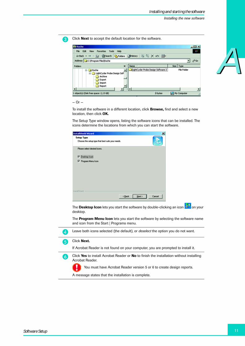
� Click Next to accept the default location for the software.
— Or —
To install the software in a different location, click Browse, find and select a new location, then click OK.
The Setup Type window opens, listing the software icons that can be installed. The icons determine the locations from which you can start the software.
The Desktop Icon lets you start the software by double-clicking an icon on your desktop.
The Program Menu Icon lets you start the software by selecting the software name and icon from the Start | Programs menu.
� Leave both icons selected (the default), or deselect the option you do not want.
� Click Next.
If Acrobat Reader is not found on your computer, you are prompted to install it.
� Click Yes to install Acrobat Reader or No to finish the installation without installing Acrobat Reader.
You must have Acrobat Reader version 5 or 6 to create design reports.
A message states that the installation is complete.
Installing and starting the software
Installing the new software

A
LightCycler Probe Design Software 2.012
A
You are now ready to use the LightCycler Probe Design Software 2.0.
� Click Finish.
� Before using the software, make sure your monitor resolution is set to a minimum of 1024 x 768.
� To start the LC PDS 2.0, double-click the LC PDS 2.0 desktop icon, or click Start | Programs | Roche | LightCycler Probe Design Software 2.0 | LightCycler Probe Design Software 2.0.
If this is the first time you have installed LC PDS 2.0, a Default Settings dialog box opens in front of the main LC PDS 2.0 window. The dialog box lets you modify the default experiment type, primer and probe melting temperatures, and other values.
If you want to modify default settings now, see “Specifying experiment and reaction settings,” in Chapter D.
You can reopen the Default Settings dialog box at any time from the Settings menu.
� To close the dialog box, click OK, or the X in the upper right corner.
Installing and starting the software
Installing the new software

AA
13Software Setup
For an overview of the software and its features see the section “Overview of windowsand menus” below.
To begin using the software see Chapter C “Designing Primers and Probes”.
2. Overview of windows and menus
This section describes the LC PDS 2.0 windows and menus. Understanding the windowsand menus will help you to follow the detailed procedures required to design primers andprobes described in Chapter C “Designing Primers and Probes”.
The main LC PDS 2.0 window is shown below, as it looks before a sequence is entered.
The LC PDS 2.0 window consists of a tab labeled Design 1, containing three subtabslabeled Sequence, Analysis, and Primer Probe Sets. The large white area in the Sequencetab will display the sequence you enter or import. At the top of the window is a menu bar.
Each portion of the window is described in more detail in the following sections.
Overview of windows and menus
Design tab

A
LightCycler Probe Design Software 2.014
A2.1 Design tab
The Design 1 tab is used to design one set of primers and probes for a single sequence.You can add additional Design tabs (Design 2, Design 3, and so on) to design additionalsets of primers and probes for the same or for a different sequence. For example, you usemultiple Design tabs if you want to design multiple sets of primers and probes for a mul-tiplex reaction.
2.2 Sequence tab
When you first open the software, the Sequence tab includes a large white area into whichyou can enter or import a DNA sequence. When you import a sequence, the name of theDesign tab is changed to the sequence file name. In the following example, Sequence 1has been imported.
2.2.1 Edit buttons
Three options at the top of the Sequence tab let you control sequence editing:
� Insert ➔ lets you enter a new base at the cursor location.
� Replace ➔ lets you select and replace a base.
� Sequence Locked ➔ locks the sequence so that it cannot be changed. If selected thebuttons Insert and Replace get inactive.
Select Sequence Locked to prevent accidental changes to the sequence.
Overview of windows and menus
Sequence tab

AA
15Software Setup
2.2.2 Design parameters
The areas on the right side of the Sequence tab let you specify design parameters. Thereare three areas:
� Experiment Type ➔ Specifies the type of primer or probe you want to design.
� Sequence Information ➔ Defines the portion of the sequence you want to analyze.The options available here depend on the type of primer or probe you specified in theExperiment Type section.
� Experiment Settings ➔ Specifies design constraints, such as the desired amplicon sizerange or melting temperature of a primer or probe. Experiment settings can also bespecified in a Settings dialog box, displayed when you click the Details button. Formore information about the Settings dialog box, see “Specifying experiment and reac-tion default settings,” in Chapter D.
The default design settings are suitable for the majority of applications. But the parame-ters of the Experimental Setting may be adapted for optimization purposes or for specialapplications:
Parameter Default Value Allowed Range
Quantification/Primers Mutation
Primer Tm 60°C 60°C
40 – 95°CProbe 1 Tm 65°C 65°C
Probe 2 Tm 68°C 68°C
Min Amplicon Size 150 bp 60 – 2,000 bp
Max Amplicon Size 300 bp
Overview of windows and menus
Sequence tab
A
LightCycler Probe Design Software 2.016
A
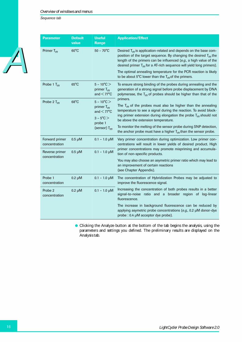
� Clicking the Analyze button at the bottom of the tab begins the analysis, using theparameters and settings you defined. The preliminary results are displayed on theAnalysis tab.
Parameter Default value
Useful Range
Application/Effect
Primer Tm 60°C 50 – 70°C Desired Tm is application-related and depends on the base com-position of the target sequence. By changing the desired Tm thelength of the primers can be influenced (e.g., a high value of thedesired primer Tm for a AT-rich sequence will yield long primers).
The optimal annealing temperature for the PCR reaction is likelyto be about 5°C lower than the Tm of the primers.
Probe 1 Tm 65°C 5 – 10°C > primer Tm and < 77°C
To ensure strong binding of the probes during annealing and thegeneration of a strong signal before probe displacement by DNApolymerase, the Tm of probes should be higher than that of theprimers.
The Tm of the probes must also be higher than the annealingtemperature to see a signal during the reaction. To avoid block-ing primer extension during elongation the probe Tm should notbe above the extension temperature.
To monitor the melting of the sensor probe during SNP detection,the anchor probe must have a higher Tm than the sensor probe.
Probe 2 Tm 68°C 5 – 10°C > primer Tm and < 77°C
3 – 5°C > probe 1 (sensor) Tm
Forward primer concentration
0.5 µM 0.1 – 1.0 µM Vary primer concentration during optimization. Low primer con-centrations will result in lower yields of desired product. Highprimer concentrations may promote mispriming and accumula-tion of non-specific products.
You may also choose an asymetric primer ratio which may lead toan improvement of certain reactions (see Chapter Appendix).
Reverse primer concentration
0.5 µM 0.1 – 1.0 µM
Probe 1 concentration
0.2 µM 0.1 – 1.0 µM The concentration of Hybridization Probes may be adjusted toimprove the fluorescence signal.
Increasing the concentration of both probes results in a bettersignal-to-noise ratio and a broader region of log-linearfluorescence.
The increase in background fluorescence can be reduced byapplying asymetric probe concentrations (e.g., 0.2 µM donor-dyeprobe : 0.4 µM acceptor dye probe).
Probe 2 concentration
0.2 µM 0.1 – 1.0 µM
Overview of windows and menus
Sequence tab

AA
17Software Setup
2.3 Analysis tab
The software analyzes each base in the sequence fragment according to various criteriaand displays the results on the Analysis tab. Use this tab to further limit the search areafor primers and probes by defining a search region for the set or for primers and probesindividually.
Higher numbers on the Y axis indicate more promising sites, lower scores indicate lessdesirable sites.
The shaded area is the search area. When you proceed witch the search, primers andprobes will be designed for this region.
The light horizontal line across the length of the graph represents the median value of allthe scores. The darker horizontal line across the shaded area represents the median scoreof that area. Note that the line moves up or down as you drag the shaded area to differentlocations in the chart.
The three options below the graph allow you to specify the search area in different ways:
� Extended ➔ Uses the entire fragment shown on the graph; the shaded area isremoved.
� Set ➔ (the default) Lets you define the search area for both primers and probes. Todefine the search region, you can move the shaded area or drag its borders to resize it.You can define the search region by entering values in the Start and End fields.
� Individual ➔ Lets you specify separate areas for the primers and probes. The shadedarea is replaced by three shaded areas, one for each primer and one for the probes. Youmove or resize each of the shaded areas individually or define the regions by enteringvalues in the Start and End fields.
The other boxes below the graph indicate the score, the fragment length, and other infor-mation for the search region.
Clicking the Single Set Search button causes the software to search the designated areaand display the results on the Primer Probe Sets tab.
Overview of windows and menus
Analysis tab
A
LightCycler Probe Design Software 2.018
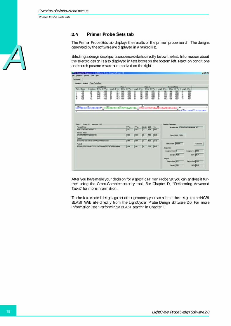
A2.4 Primer Probe Sets tab
The Primer Probe Sets tab displays the results of the primer probe search. The designsgenerated by the software are displayed in a ranked list.
Selecting a design displays its sequence details directly below the list. Information aboutthe selected design is also displayed in text boxes on the bottom left. Reaction conditionsand search parameters are summarized on the right.
After you have made your decision for a specific Primer Probe Set you can analyze it fur-ther using the Cross-Complementarity tool. See Chapter D, “Performing AdvancedTasks,” for more information.
To check a selected design against other genomes, you can submit the design to the NCBIBLAST Web site directly from the LightCycler Probe Design Software 2.0. For moreinformation, see “Performing a BLAST search” in Chapter C.
Overview of windows and menus
Primer Probe Sets tab

AA
19Software Setup
2.5 Menus
At the top of the LightCycler Probe Design Software 2.0 window are menus used to per-form standard Windows functions, as well as specialized LC PDS 2.0 functions.
The options on each menu are described below.
2.5.1 File menu
The File menu contains the following options:
� New, Open, Save, Save As, Page Setup ➔ These commands function as they do inother Windows programs.
� Print Window ➔ Prints an image of the current window.
� Print Report ➔ Creates a PDF version of a selected primer probe design and displaysit in a preview window. From the preview window you can print the report
� Open Report ➔ Opens a previously saved report.
� Numbered list of previously saved designs ➔ Select a design file to reopen it.
� Exit ➔ Closes the LightCycler Probe Design Software 2.0.
Overview of windows and menus
Menus

A
LightCycler Probe Design Software 2.020
A2.5.2 Sequence menu
The Sequence menu contains the following options:
� Add Empty ➔ Adds a new Design tab containing three subtabs. Use Add Emptywhenever you want to start a new primer probe design search, in addition to thedesigns you already have open in the window.
� Clear ➔ Deletes the sequence from the currently displayed Design tab, but leaves thetab open.
� Delete ➔ Closes the currently displayed Design tab.
� Import ➔ Allows to import a sequence in common formats, such as GenBank, EMBLand Fasta or from previously saved LC PDS files (*.lpd files created with LCPDS1 or*.spd files created with LCPDS2). After you select a format, the software displays adialog box you can use to find and import a sequence.
� Export ➔ Displays two options: Fasta and To Order. Selecting Fasta exports thesequence in Fasta Format. Selecting To Order lets you save the results as an XML file.
Overview of windows and menus
Menus

AA
21Software Setup
2.5.3 Settings menu
The Settings menu contains the following options:
� Comments ➔ Displays any comments associated with the sequence (such as headerinformation of GenBank or EMBL) or displays an empty comments box so you canadd comments.
� Current Settings ➔ Displays the Settings dialog box. Use the dialog box to specifysettings for the current sequence, such as amplicon size and melting temperatures andto specify reaction conditions for the current sequence, such as used buffer, concentra-tions of oligonucleotides and dNTPs. Some of the options in this dialog box can alsobe set on the Sequence tab. The options specified in the Current Settings dialog boxapply to the current experiment only.
� Default Settings ➔ Displays a dialog box similar to the Settings dialog box, but thesettings specified here are the defaults for all new designs. Default settings are overrid-den by settings in the Current Settings dialog box.
For more information about default settings, see “Specifying experiment and reactiondefault settings” in Chapter D.
� Top 50, Limit Sets, Show All Sets ➔ These options let you specify how many resultsets to display. For more information, see “Viewing and saving result sets,” inChapter C.
Overview of windows and menus
Menus

A
LightCycler Probe Design Software 2.022
A2.5.4 Tools menu
The Tools menu contains the following options:
� Fixed Oligos options ➔ These two options open the Fixed Oligos tool, used to specifyan existing oligo you want to use in the primer probe design. For more information,see “Using existing oligos in a design,” in Chapter C.
� Cross Comp Tool options ➔ These three options open the Cross-Complementaritiestool, used to analyze a potential design for cross-complementarities between primersand probes. For more information, see “Analyzing a design for cross-complementari-ties,” in Chapter D.
� Show Alignment of Current Selection ➔ This option opens a dialog box containingthe DNA sequence being analyzed, with the primer and probe sites displayed in color.
� BLAST options ➔ These two options open a dialog box you can use for submittingprimers of a selected design to the NCBI BLAST Web site.
� Multiplex options ➔ These options are used to perform a multiplex analysis, in whichthe software searches for primers and probes that are compatible across multiple DNAsequences. For more information, see “Designing primers and probes for a multiplexreaction,” in Chapter D.
2.5.5 Help menu
The Help menu provides access to the software user manual and other information.
Overview of windows and menus
Menus

BPrinciples of Primer and Probe Design

BB
LightCycler Probe Design Software 2.024
1. How primers and probes work in quantification reactions ..................................................... 251.1 HybProbe Probes for quantification ............................................................................................................ 26
1.1.1 HybProbe Probes ........................................................................................................................................ 261.2 The role of primers used with SYBR Green I dye ................................................................................... 28
2. How primers and probes work in mutation detection reactions ......................................... 282.1 Mutation detection formats ............................................................................................................................ 29
2.1.1 SimpleProbe .................................................................................................................................................. 292.1.2 HybProbe ........................................................................................................................................................ 292.1.3 HybProbe Plus .............................................................................................................................................. 31
3. General requirements of good primer and probe design ......................................................... 323.1 Avoid inter- or intra-molecular homologies ............................................................................................. 323.2 Avoid negative sequence motifs ................................................................................................................... 333.3 Appropriate melting temperature ................................................................................................................ 343.4 Single annealing site ......................................................................................................................................... 343.5 Other restrictions ................................................................................................................................................ 35
4. Additional requirements for designing mutation-detection probes .................................. 35
B Principles of Primers and Probe Design Page
Principles of Primer and Probe Design

BB
25Principles of Primer and Probe Design
Principles of Primer and Probe Design
Many factors affect the design of primers and probes for a quantification or a mutationdetection reaction. This chapter discusses the following topics:
� How primers and probes work in quantification reactions
� How probes work in mutation detection reactions
� Types of probes you can design for quantification or mutation detection reactions
� Key factors affecting the quality of primer and probe designs
Read this chapter if you are new to primer probe design or want to review design basicprinciples. Understanding the principles of good primer and probe design will help youto make design choices and to evaluate the LC PDS 2.0 design results.
1. How primers and probes work in quantification reactions
In a typical quantification reaction, the reaction mix is first heated in order to separate(denature) the double-stranded target DNA. The temperature is then lowered during theannealing step of PCR. As the temperature is lowered, pairs of dye-labeled probes bindclose together on complementary sequences of one of the single DNA strands. This bind-ing, or hybridization, of a probe pair results in an energy transfer between the fluorescentdyes of the two probes. The PCR instrument measures the increase in fluorescence ineach reaction during this process. For more information about the energy transfer pro-cess, see “HybProbe Probes for quantification,” below.
As the reaction is cooled, primers in the mix bind to the forward and reverse strands ofDNA. Taq polymerase incorporates deoxynucleoside triphosphates (dNTPs) into thereaction, causing the dNTPs to bind to the single DNA strands, beginning at the 3’ end ofthe primers. The polymerase and dNTPs continue to extend until the polymerase falls offor the temperature in the reaction is increased, causing the newly synthesized strands ofDNA to denature again.
The heating and cooling cycle is repeated multiple times, producing more DNA productwith each cycle. As the amount of DNA increases, the amount of fluorescence measuredby the PCR instrument increases. The increase in fluorescence, along with a standardcurve, can be used to determine the amount of DNA in the samples.
For a quantification reaction, you typically design a primer probe set that includes thefollowing:
� Forward and reverse primers to elongate each of the DNA strands
� A pair of hybridization probes to provide fluorescence
You can also use SYBR Green I dye in place of probes. For more information aboutprobes and about SYBR Green I dye, see the following sections.
How primers and probes work in quantification reactions

BB
LightCycler Probe Design Software 2.026
1.1 HybProbe Probes for quantification
You can design the following type of probes for a quantification reaction
1.1.1 HybProbe Probes
HybProbe Probes are two sequence-specific hybridization probes labeled with fluores-cent dyes that are designed to bind close together on a single DNA strand.
The detection principle of dual hybridization probes is called fluorescence resonanceenergy transfer (FRET). FRET involves the transfer of energy from a donor fluorophoreon one probe to an acceptor fluorophore on the other. If the donor and the acceptor flu-orophore are very close together, excitation of the donor by the blue light (LED) of themachine results in energy transfer to the acceptor, which emits light of a longer wave-length that can be measured. Increasing amounts of fluorescence during a quantificationreaction indicate increasing amounts of DNA.
HybProbe Probes must be designed as a pair with each probe labeled with either thedonor dye (Fluorescein) or the acceptor dye (either LightCycler Red 610, LightCycler Red640, LightCycler Red 670 or LightCycler Red 705). Because the FRET process decreaseswith the sixth power of distance, hybridization probes must be separated by no morethan 1 – 5 nucleotides.
How primers and probes work in quantification reactions
HybProbe Probes for quantification

BB
27Principles of Primer and Probe Design
The following table illustrates a quantification reaction using HybProbe Probes.
Role of primers and HybProbe Probes in a quantification reaction
A Denaturation During Denaturation, the reaction mix is heated, causing the template DNA to separate. The PCR template, primers and HybProbe Probes are now all single-stranded. One HybProbe Probe is labeled with the fluorescent donor dye Fluores-cein, the other one is labeled with an acceptor dye (such as LightCycler Red 610, LightCycler Red 640, LightCycler Red 670 or LightCycler Red 705). The donor dye is excited by blue light of 470 nm and emits green light of 530 nm.
B Annealing After cooling to the annealing tempera-ture PCR primers and HybProbe Probes hybridize to their complementary regions. The donor dye now comes into close proximity to the acceptor dye. Energy emitted from the donor dye excites the acceptor dye, which now emits red light of 610, 640, 670 or 705 nm. The red light is measured by the PCR instrument.
C Elongation After annealing to their target sites, the primers are elongated by thermostable DNA polymerase.
D Completion The amount of template DNA has dou-bled and, as the elongation step nears its end, the DNA is double-stranded. The HybProbe Probes have been displaced from their target sites. The next cycle of PCR is ready to start again at step A.
Principles of Primer and How primers and probes work in quantification reactions
HybProbe Probes for quantification

BB
LightCycler Probe Design Software 2.028
1.2 The role of primers used with SYBR Green I dye
You can use SYBR Green I dye instead of a probe to provide the fluorescence measured bythe PCR instrument. Unlike a probe, SYBR Green I dye binds only to double-strandedDNA and therefore binds after the annealing step in the PCR quantification cycle. SYBRGreen I dye is not sequence-specific, but instead binds to any double-stranded DNAproduct.
If you use SYBR Green I dye, you need to design only the primers needed to amplify theDNA of interest. SYBR Green I requires very specific primers, so that the increase in fluo-rescence indicates the increase in the target DNA and not any DNA products that mightbe present in the reaction, such as primer dimers or other non-specific products.
The LightCycler Probe Design Software 2.0 includes a primers-only module you can useto design primers for use with SYBR Green I dye.
2. How primers and probes work in mutation detection reactions
If a reaction mix is heated after fluorescent probes have bound to the single DNA strands,the probes separate from the strands, causing a decrease in the measured fluorescence.The result is a downward curve in fluorescence visible on the PCR instrument’s fluores-cence chart. The curve is referred to as a “melt curve.” The shape of the curve and thetemperature at which half the probes have melted off the DNA strands (called the meltingtemperature or Tm) are different for different DNA products.
To detect the presence of a mutation in the target DNA, you can heat the reaction mixafter the probes have bound to the DNA and then observe the Tm and the characteristicsof the resulting melt curve.
When a labeled probe for the wild type hybridizes to a mutant DNA sequence, the mis-match in base pairing causes a destabilizing effect on the probe, lowering the temperatureat which the probe melts off the target sequence. The melting temperature shift (�Tm)between a normal allele-probe match and a mutated allele-probe mismatch results in dif-ferent fluorescence profiles, which indicate the presence of a mutation. The difference inmelting temperature depends on the type of mismatch, the mismatch position within theprobe sequence, and the base pairs immediately adjacent to the mismatch.
To detect mutations, you must design sequence-specific probes that provide differentmelting temperatures (approx. 5°C) between the normal probe-allele combination andthe mismatched probe-allele combination.
How primers and probes work in mutation detection reactions
The role of primers used with SYBR Green I dye

BB
29Principles of Primer and Probe Design
2.1 Mutation detection formats
You can use three probe formats for mutation analysis:
� SimpleProbe
� HybProbe
� HybProbe Plus
2.1.1
A SimpleProbe Probe is a sequence-specific hybridization probe that fluoresces when itbinds to a single DNA strand. In a mutation detection reaction, if there is a mismatchunder the SimpleProbe Probe, the probe melts off at a lower temperature than if theprobe is perfectly matched to the sequence. The difference in melting temperature canindicate the presence of the mutation. The SimpleProbe Probe must be designed to fitcentric over the mutation site (or sites) and should provide the largest difference in melt-ing temperature between a perfect match and a mismatch. SimpleProbe Probes can bedesigned either at the 5’ or 3’ end. For fragments too short for HybProbe Probes, usingSimpleProbe Probes might be advantageous.
A guanine at or near the dye end is not recommended and is penalized duringdesign scoring.
2.1.2
HybProbe Probes are two sequence-specific oligos labeled with fluorescent dyes that aredesigned to bind close together on a single DNA strand. The detection principle of dualhybridization probes is called fluorescence resonance energy transfer (FRET). For adescription of the FRET process, see “HybProbe Probes for quantification” above.
Like SimpleProbe Probes, HybProbe Probes can be used to detect mutations by meltingcurve analysis. One probe, called the sensor probe, is designed to bind over one or moremutation sites. The other probe, called the anchor probe, must be separated by no morethan one to five nucleotides from the sensor probe. HybProbe Probes must be designedas a pair with each probe labeled with either the donor or the acceptor dye.
How primers and probes work in mutation detection reactions
Mutation detection formats

BB
LightCycler Probe Design Software 2.030
When the reaction mix is heated, the probes separate from the target strands, causing anincrease in the distance between the two dyes and a consequent decrease in measured flu-orescence. If there is a mismatch under the sensor probe, the probe melts off at a lowertemperature than if the probe is perfectly matched. The difference in melting tempera-ture between mismatched probe-target combinations and perfectly matched probe-tar-get combinations can indicate the presence of the mutation. For mutation detection,probes should be designed to provide a large difference in melting temperature betweenperfectly matched probe-target combinations and the mismatched probe-target combi-nation.
The following table illustrates a mutation detection reaction using HybProbe Probes.
How primers and probes work in mutation detection reactions
Mutation detection formats
BB
31Principles of Primer and Probe Design
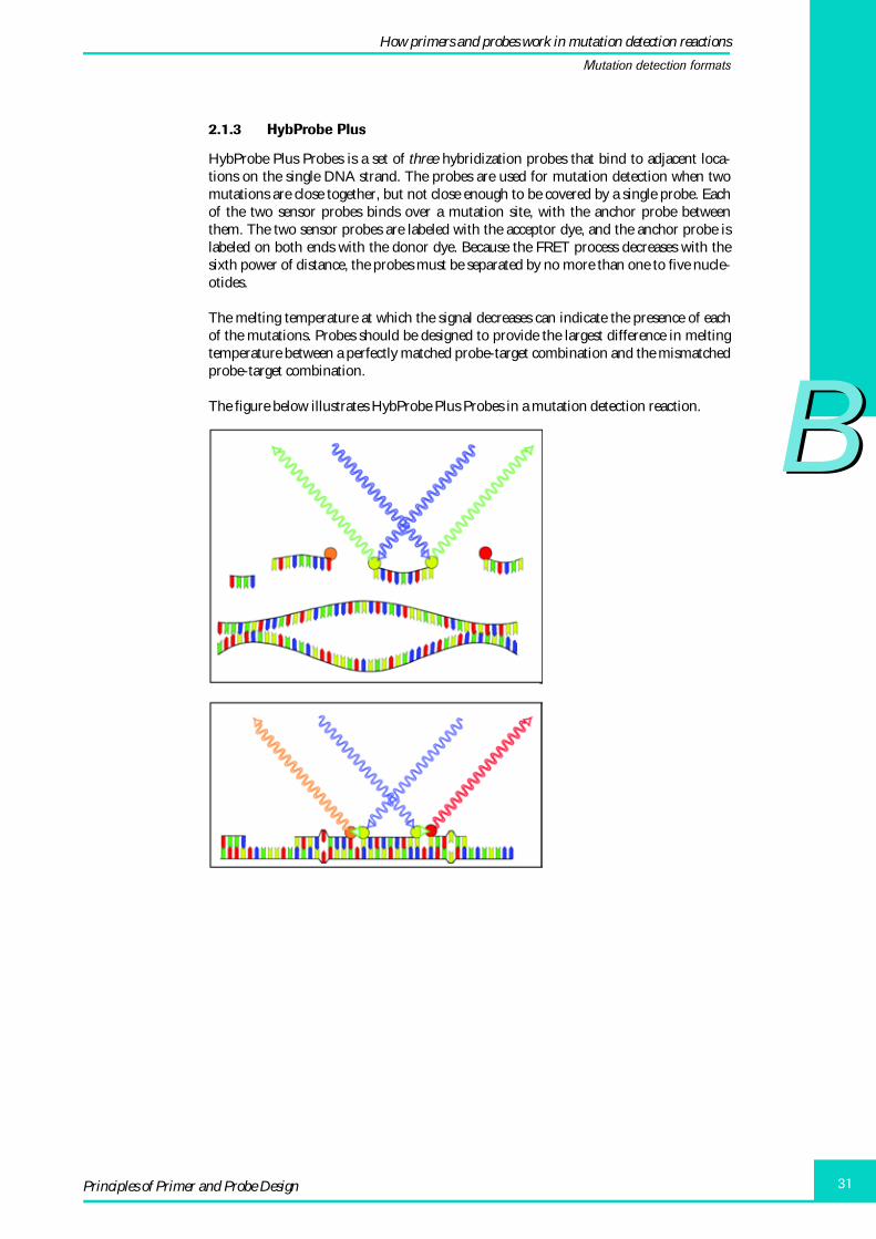
2.1.3 HybProbe Plus
HybProbe Plus Probes is a set of three hybridization probes that bind to adjacent loca-tions on the single DNA strand. The probes are used for mutation detection when twomutations are close together, but not close enough to be covered by a single probe. Eachof the two sensor probes binds over a mutation site, with the anchor probe betweenthem. The two sensor probes are labeled with the acceptor dye, and the anchor probe islabeled on both ends with the donor dye. Because the FRET process decreases with thesixth power of distance, the probes must be separated by no more than one to five nucle-otides.
The melting temperature at which the signal decreases can indicate the presence of eachof the mutations. Probes should be designed to provide the largest difference in meltingtemperature between a perfectly matched probe-target combination and the mismatchedprobe-target combination.
The figure below illustrates HybProbe Plus Probes in a mutation detection reaction.
How primers and probes work in mutation detection reactions
Mutation detection formats

BB
LightCycler Probe Design Software 2.032
3. General requirements of good primer and probe design
Optimal primer and probe designs for any reaction must meet the following generalrequirements:
� Primers contain few or no intra-molecular sequence homologies (self-complementarysequences). Primer-probe sets contain few or no inter-molecular sequence homolo-gies (cross-complementary sequences that cause binding between a probe and aprimer).
� The sequences of both the PCR template and the primers and probes contain as fewsuboptimal motifs as possible.
� The primers and probes have the desired melting temperatures.
� The primers (and to a lesser extent the probes) have a single annealing site on the PCRtemplate and do not have annealing sites elsewhere on the target genome or ongenomes of other contaminating organisms.
� The designs meet various other criteria, such as the specified amplicon size, thespacing between FRET partners, and the required gap between primers and probes.
No primer or probe design is likely to meet all of the criteria completely. The softwareassesses how closely a design meets the criteria, assigns a score to each design, and pre-sents the results in a ranked list.
Each of the general criteria is discussed in more detail in the following sections.
3.1 Avoid inter- or intra-molecular homologies
Primers or probes with intra-molecular homologies (self-complementary sequences) canform secondary structures, such as hairpins, or can cause the primers themselves toextend (and be amplified), instead of amplifying the target DNA.
Primer-probe sets with inter-molecular homologies (complementarities betweensequences) can bind to each other, causing unwanted product.
Other undesired homologies include complements between either a primer or probe andthe wrong location in the target DNA, genomic DNA or DNA from another organismthat might be included in an environmental sample.
After the software presents a list of possible primer and probe designs, you can use theLightCycler Probe Design Software 2.0 Cross-Comp Tool to review each design for crosscomplementarities, including self-complementarities. For more information about usingthe tool, see “Analyzing a design for cross-complementarities,” in Chapter D.
To look for binding sites on other genomes you can also submit a design to the NCBIBLAST Web site directly from the Probe Design Software 2.0. For more informationabout performing a BLAST search, see “Performing a BLAST search” in Chapter C.
General requirements of good primer and probe design
Avoid inter- or intra-molecular homologies
BB
33Principles of Primer and Probe Design
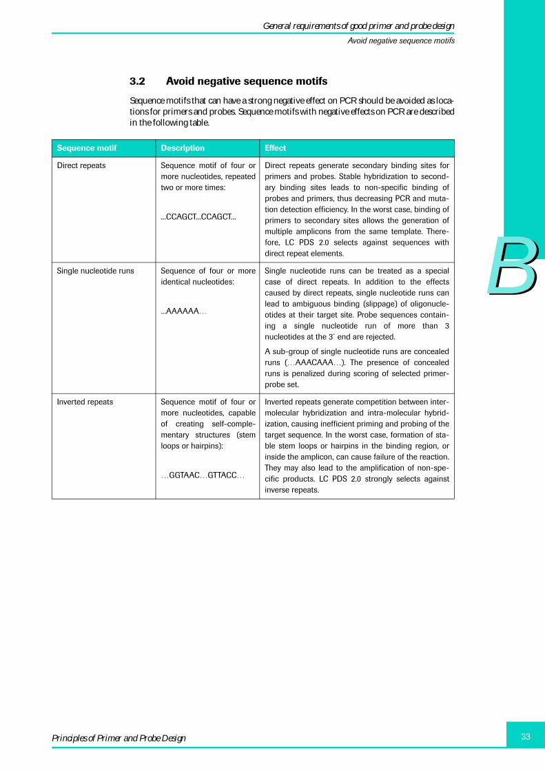
3.2 Avoid negative sequence motifs
Sequence motifs that can have a strong negative effect on PCR should be avoided as loca-tions for primers and probes. Sequence motifs with negative effects on PCR are describedin the following table.
Sequence motif Description Effect
Direct repeats Sequence motif of four ormore nucleotides, repeatedtwo or more times:
...CCAGCT...CCAGCT...
Direct repeats generate secondary binding sites forprimers and probes. Stable hybridization to second-ary binding sites leads to non-specific binding ofprobes and primers, thus decreasing PCR and muta-tion detection efficiency. In the worst case, binding ofprimers to secondary sites allows the generation ofmultiple amplicons from the same template. There-fore, LC PDS 2.0 selects against sequences withdirect repeat elements.
Single nucleotide runs Sequence of four or moreidentical nucleotides:
...AAAAAA…
Single nucleotide runs can be treated as a specialcase of direct repeats. In addition to the effectscaused by direct repeats, single nucleotide runs canlead to ambiguous binding (slippage) of oligonucle-otides at their target site. Probe sequences contain-ing a single nucleotide run of more than 3nucleotides at the 3´ end are rejected.
A sub-group of single nucleotide runs are concealedruns (…AAACAAA…). The presence of concealedruns is penalized during scoring of selected primer-probe set.
Inverted repeats Sequence motif of four ormore nucleotides, capableof creating self-comple-mentary structures (stemloops or hairpins):
…GGTAAC…GTTACC…
Inverted repeats generate competition between inter-molecular hybridization and intra-molecular hybrid-ization, causing inefficient priming and probing of thetarget sequence. In the worst case, formation of sta-ble stem loops or hairpins in the binding region, orinside the amplicon, can cause failure of the reaction.They may also lead to the amplification of non-spe-cific products. LC PDS 2.0 strongly selects againstinverse repeats.
General requirements of good primer and probe design
Avoid negative sequence motifs

BB
LightCycler Probe Design Software 2.034
3.3 Appropriate melting temperature
For HybProbe Probes, it is important that primers and probes do not melt at the sametemperature. Follow the guidelines in the table below when specifying melting tempera-tures for HybProbe Probes.
The software calculates the Tm for the primer and probe designs based on the experimen-tal conditions (concentrations of primers and probes, concentrations of dNTPs, salt com-position of the reaction buffer) and matches them as closely as possible to the Tm valuesyou designate in the software.
Thermodynamic analysis is used to match the Tm values of the primers and to pair theprimers with the appropriate probes. Selection of the primers and probes is performed bycalculating the Tm of the oligonucleotides using the unified nearest neighbor thermo-dynamics approach (J. SantaLucia, 1998).
Calculating the Tm by thermodynamic analysis is also used to predict the Tm shiftbetween matched and mismatched probes in single-nucleotide polymorphism detectionexperiments.
3.4 Single annealing site
Optimal primers and probes should have only one annealing site in the sequence tem-plate, no annealing sites in the rest of the target genome, and no annealing sites ingenomes of other organisms, if the DNA of the other organisms could be included in thereaction (for example, if other organisms could be present in an environmental sample).
Searching for non-target primer binding is especially important when working withmutations in the human genome. If the primers are complementary to other sections ofthe DNA, amplification of this non-target sequence is possible. Probes containing repeti-tive sequences may also be a problem, since the probes will produce a fluorescent signalwhen they hybridize to these repetitive regions. In the human genome, pseudogenes tothe gene of interest may bind both primers and probes. Pseudogenes may be quite similarto the target region, however they usually contain mutations not present in the gene. The
Guideline for HybProbe Tm
Comment
Probe Tm should be5 – 10°C higher thanthat of the primers
For successful generation of a fluorescence signal, both HybProbeoligonucleotides have to bind simultaneously to the single-stranded target DNA during the annealing phase of PCR.
Because primers are elongated by Taq DNA Polymerase immedi-ately after annealing, even at temperatures below 72°C, this couldlead to early displacement of the probes by the polymerase or evento prevention of probe binding due to covering of the probe bind-ing site by the newly synthesized DNA strand.
Thus, the Tm of probes should be higher than that of the primers toensure strong binding of probes during annealing and generationof a signal before probe displacement by DNA polymerase.
Probe binding shouldnot be too stable(avoid a Tm 10 – 20°Chigher than primerTm)
Extremely stable probes may interfere with the amplification pro-cess by hindering the Taq DNA Polymerase and lowering the sensi-tivity of the assay.
General requirements of good primer and probe design
Appropriate melting temperature

BB
35Principles of Primer and Probe Design
result of amplifying and detecting pseudogenes can be the addition of ‘new’ melt peaks orconstant detection of the mutant.
Sequence homology searches provide a quick method of scanning DNA sequences storedin databases against a query sequence. By searching non-target sequences for homologyto the primer sequences, all potential targets for the primer set can be discovered. Of par-ticular importance are those sequences that stably bind both the forward and reverseprimer in the correct orientation and within amplification range. Probe sequences withhomology to non-target regions are important only if the primers can amplify thesequence or the probe has homology to many non-target sites. Primer-probe sets withsignificant homology to non-target regions should be redesigned to new areas of the tar-get.
The LC PDS 2.0 includes a tool you can use to start a basic BLAST search from within thesoftware.
3.5 Other restrictions
You can specify various additional requirements that constrain the primer probe design,including:
� Fragment length
� Choice of forward or reverse strand for the annealing site
� Amplicon size range
� Dye type and dye end
� Reaction conditions
� Size ranges for primers and probes
4. Additional requirements for designing mutation-detection probes
As the software scores mutation detection probe designs, it considers the followingrequirements:
� The sensor probe must be located over the mutation site.
� When using HybProbe Probes, the difference in melting temperature between the sen-sor probe over a mismatch and the sensor probe over a match must be sufficient todetect the mutation.
� The anchor probe must have a Tm that is approx. 5°C higher than the sensor probe toensure that the sensor probe always melts off first.
� Sensor probes must have mismatch positions at least three base pairs away from theprobe end.
Primer probe sets that do not meet these requirements are penalized during the designprocess.
Additional requirements for designing mutation-detection probes
Other restrictions

BB
LightCycler Probe Design Software 2.036

CDesigning Primers and Probes

CC
LightCycler Probe Design Software 2.038
1 Providing a DNA sequence ....................................................................................................................... 39
2. Specifying reaction conditions ............................................................................................................... 43
3. Specifying design parameters ................................................................................................................. 443.1 Choosing the experiment and probe type ................................................................................................ 443.2 Specifying sequence information for quantification probes or primers only .............................. 453.3 Specifying sequence information for mutation detection probes ................................................... 473.4 Specifying experiment settings ..................................................................................................................... 50
4. Analyzing and selecting the design region ...................................................................................... 52
5. Viewing and saving results ....................................................................................................................... 545.1 How scores are displayed on the Primer Probe Sets tab .................................................................... 565.2 Viewing primers and probes within the sequence fragment ............................................................. 57
6. Exporting a design as an XML file ........................................................................................................ 57
7. Using existing oligos in a design ........................................................................................................... 58
8. Printing windows and reports .................................................................................................................. 60
9. Performing a BLAST search ...................................................................................................................... 62
C Designing Primers and Probes Page
Designing Primers and Probes

CC
39Designing Primers and Probes
Designing Primers and Probes
To design a primer or probe, follow the general steps below; each step is described inmore detail in the following sections:
For information about advanced procedures, including performing a cross-complemen-tarity analysis or designing primers and probes for multiplex reactions, see Chapter D“Advanced Tasks.”
1. Providing a DNA sequence
To provide the target DNA sequence, you can import a sequence, copy and paste thesequence from another source, or enter the sequence manually. If necessary, you can editthe sequence after it has been entered.
The sequence must contain at least 160 bases.
To enter a sequence manually
� Provide the DNA sequence to be analyzed.
� Specify reaction conditions.
� Specify design parameters.
� Click Analyze to begin the preliminary analysis.
� After the software performs the preliminary scoring analysis, define the search region for the primer and probe sites.
� After the software searches the region, review the ranked results.
� (Optional) Submit selected designs to the NCBI BLAST Web site.
� (Optional) Print the analysis windows or generate a design report.
Save or export the analysis.
� If an empty Design tab is not available, from the Settings menu, select Add Empty.
� Click in the window of the Sequence tab, then type the sequence. Valid characters are A, C, G, T, U (mRNA), and N (unknown).
Providing a DNA sequence

CC
LightCycler Probe Design Software 2.040
To copy and paste a sequence
To import Sequence Database Files
The two major nucleic acid sequence databases are GenBank and the EMBL NucleotideSequence Database. GenBank is an annotated collection of all publicly available DNAsequences and the genetic sequence database of the US National Institute of Health. TheEMBL database is used as a similar database, operated by the European BioinfomaticsInstitute.
Both databases are accessible via the Internet:
� GenBank: http://www.ncbi.nlm.nih.gov/Entrez/index.html (February 2004)
� EMBL: http://www.ebi.ac.uk/embl/ (February 2004)
Both databases use their own sequence file format, which are similar in consisting aheader, which contains general information, such as keywords, author names, source,organism and the actual nucleic acid sequence. The GenBank sequence format can easilybe identified by the entry ‘ORIGIN’ at the beginning of the nucleic acid sequence.
Save the search file under a *.txt extension in your ‘Import’ Folder of LC PDS 2.0.
� If an empty Design tab is not available, from the Settings menu, select Add Empty.
� Copy the sequence from another source.
� Click in the white area of the Sequence tab, then press Ctrl-V to paste the sequence.
Providing a DNA sequence

CC
41Designing Primers and Probes
The FASTA Format:
The GenBank Format:LOCUS 4292 bp DNA linear BCT 12-SEP-1993DEFINITION My gene of interestACCESSION X12345VERSION X12345.1KEYWORDS My gene of interestSOURCE XXXXXX ORGANISM XXXXXX
XXXXXXREFERENCE 1 (bases 1 to 4292)AUTHORS Names of Authors
·····
ORIGIN 1 tcaaagtatt tgtatttatg gtcatttaaa taattaataa tttaattaat tttaaatatt61 ataagaggtg ttaaatatgc aatttgttaa taaacaattt aattataaag atcctgtaaa121 tggtgttgat attgcttata taaaaattcc aaatgtagga caaatgcaac cagtaaaagc181 ttttaaaatt cataataaaa tatgggttat tccagaaaga gatacattta caaatcctga241 agaaggagat ttaaatccac caccagaagc aaaacaagtt ccagtttcat attatgattc301 aacatattta agtacagata atgaaaaaga taattattta aagggagtta caaaattatt361 tgagagaatt tattcaactg atcttggaag aatgttgtta acatcaatag taaggggaat421 accattttgg ggtggaagta caatagatac agaattaaaa gttattgata ctaattgtat481 taatgtgata caaccagatg gtagttatag atcagaagaa cttaatctag taataatagg541 accctcagct gatattatac agtttgaatg taaaagcttt ggacatgaag ttttgaatct601 tacgcgaaat ggttatggct ctactcaata cattagattt agcccagatt ttacatttgg661 ttttgaggag tcacttgaag ttgatacaaa tcctctttta ggtgcaggca aatttgctac721 agatccagca gtaacattag cacatgaact tatacatgct ggacatagat tatatggaat781 agcaattaat ccaaataggg tttttaaagt aaatactaat gcctattatg aaatgagtgg841 gttagaagta agctttgagg aacttagaac atttggggga catgatgcaa agtttataga901 tagtttacag gaaaacgaat ttcgtctata ttattataat aagtttaaag atatagcaag961 tacacttaat aaagctaaat caatagtagg tactactgct tcattacagt atatgaaaaa1021 tgtttttaaa gagaaatatc tcctatctga agatacatct ggaaaatttt cggtagataa1081 attaaaattt gataagttat acaaaatgtt aacagagatt tacacagagg ataattttgt1141 taagtttttt aaagtactta acagaaaaac atatttgaat tttgataaag ccgtatttaa1201 gataaatata gtacctaagg taaattacac aatatatgat ggatttaatt taagaaatac1261 aaatttagca gcaaacttta atggtcaaaa tacagaaatt aataatatga attttactaa1321 actaaaaaat tttactggat tgtttgaatt ttataagttg ctatgtgtaa gagggataat1381 aacttctaaa actaaatcat tagataaagg atacaataag gcattaaatg atttatgtat1441 caaagttaat aattgggact tgttttttag tccttcagaa gataatttta ctaatgatct1501 aaataaagga gaagaaatta catctgatac taatatagaa gcagcagaag aaaatattag1561 tttagattta atacaacaat attatttaac ctttaatttt gataatgaac ctgaaaatat1621 ttcaatagaa aatctttcaa gtgacattat aggccaatta gaacttatgc ctaatataga1681 aagatttcct aatggaaaaa agtatgagtt agataaatat actatgttcc attatcttcg1741 tgctcaagaa tttgaacatg gtaaatctag gattgcttta acaaattctg ttaacgaagc1801 attattaaat cctagtcgtg tttatacatt tttttcttca gactatgtaa agaaagttaa1861 taaagctacg gaggcagcta tgtttttagg ctgggtagaa caattagtat atgattttac1921 cgatgaaact agcgaagtaa gtactacgga taaaattgcg gatataacta taattattcc1981 atatatagga cctgctttaa atataggtaa tatgttatat aaagatgatt ttgtaggtgc2041 tttaatattt tcaggagctg ttattctgtt agaatttata ccagagattg caatacctgt2101 attaggtact tttgcacttg tatcatatat tgcgaataag gttctaaccg ttcaaacaat2161 agataatgct ttaagtaaaa gaaatgaaaa atgggatgag gtctataaat atatagtaac2221 aaattggtta gcaaaggtta atacacagat tgatctaata agaaaaaaaa tgaaagaagc2281 tttagaaaat caagcagaag caacaaaggc tataataaac tatcagtata atcaatatac2341 tgaggaagag aaaaataata ttaattttaa tattgatgat ttaagttcga aacttaatga2401 gtctataaat aaagctatga ttaatataaa taaatttttg aatcaatgct ctgtttcata2461 tttaatgaat tctatgatcc cttatggtgt taaacggtta gaagattttg atgctagtct2521 taaagatgca ttattaaagt atatatatga taatagagga actttaattg gtcaagtaga2581 tagattaaaa gataaagtta ataatacact tagtacagat ataccttttc agctttccaa2641 atacgtagat aatcaaagat tattatctac atttactgaa tatattaaga atattattaa2701 tacttctata ttgaatttaa gatatgaaag taatcattta atagacttat ctaggtatgc2761 atcaaaaata aatattggta gtaaagtaaa ttttgatcca atagataaaa atcaaattca2821 attatttaat ttagaaagta gtaaaattga ggtaatttta aaaaatgcta ttgtatataa2881 tagtatgtat gaaaatttta gtactagctt ttggataaga attcctaagt attttaacag2941 tataagtcta aataatgaat atacaataat aaattgtatg gaaaataatt caggatggaa3001 agtatcactt aattatggtg aaataatctg gactttacag gatactcagg aaataaaaca3061 aagagtagtt tttaaataca gtcaaatgat taatatatca gattatataa acagatggat3121 ttttgtaact atcactaata atagattaaa taactctaaa atttatataa atggaagatt3181 aatagatcaa aaaccaattt caaatttagg taatattcat gctagtaata atataatgtt3241 taaattagat ggttgtagag atacacatag atatatttgg ataaaatatt ttaatctttt3301 tgataaggaa ttaaatgaaa aagaaatcaa agatttatat gataatcaat caaattcagg3361 tattttaaaa gacttttggg gtgattattt acaatatgat aaaccatact atatgttaaa3421 tttatatgat ccaaataaat atgtcgatgt aaataatgta ggtattagag gttatatgta3481 tcttaaaggg cctagaggta gcgtaatgac tacaaacatt tatttaaatt caagtttgta3541 tagggggaca aaatttatta taaaaaaata tgcttctgga aataaagata atattgttag3601 aaataatgat cgtgtatata ttaatgtagt agttaaaaat aaagaatata ggttagctac3661 taatgcatca caggcaggcg tagaaaaaat actaagtgca ttagaaatac ctgatgtagg3721 aaatctaagt caagtagtag taatgaagtc aaaaaatgat caaggaataa caaataaatg3781 caaaatgaat ttacaagata ataatgggaa tgatataggc tttataggat ttcatcagtt
The EMBL Format:ID standard; genomic DNA; PRO; 4292 BP.XXAC X12345XXSV X12345.1XXDT 07-MAY-1990 (Rel. 24, Created)DT 12-SEP-1993 (Rel. 36, Last updated, Version 3)XXDE XXXXXXXX
····
SQ Sequence 4292 BP; 1738 A; 423 C; 668 G; 1463 T; 0 other;tcaaagtatt tgtatttatg gtcatttaaa taattaataa tttaattaat tttaaatatt 60ataagaggtg ttaaatatgc aatttgttaa taaacaattt aattataaag atcctgtaaa 20tggtgttgat attgcttata taaaaattcc aaatgtagga caaatgcaac cagtaaaagc 180ttttaaaatt cataataaaa tatgggttat tccagaaaga gatacattta caaatcctga 240agaaggagat ttaaatccac caccagaagc aaaacaagtt ccagtttcat attatgattc 300aacatattta agtacagata atgaaaaaga taattattta aagggagtta caaaattatt 360tgagagaatt tattcaactg atcttggaag aatgttgtta acatcaatag taaggggaat 420accattttgg ggtggaagta caatagatac agaattaaaa gttattgata ctaattgtat 480taatgtgata caaccagatg gtagttatag atcagaagaa cttaatctag taataatagg 540accctcagct gatattatac agtttgaatg taaaagcttt ggacatgaag ttttgaatct 600tacgcgaaat ggttatggct ctactcaata cattagattt agcccagatt ttacatttgg 660ttttgaggag tcacttgaag ttgatacaaa tcctctttta ggtgcaggca aatttgctac 720agatccagca gtaacattag cacatgaact tatacatgct ggacatagat tatatggaat 780agcaattaat ccaaataggg tttttaaagt aaatactaat gcctattatg aaatgagtgg 840gttagaagta agctttgagg aacttagaac atttggggga catgatgcaa agtttataga 900tagtttacag gaaaacgaat ttcgtctata ttattataat aagtttaaag atatagcaag 960tacacttaat aaagctaaat caatagtagg tactactgct tcattacagt atatgaaaaa 1020tgtttttaaa gagaaatatc tcctatctga agatacatct ggaaaatttt cggtagataa 1080attaaaattt gataagttat acaaaatgtt aacagagatt tacacagagg ataattttgt 1140taagtttttt aaagtactta acagaaaaac atatttgaat tttgataaag ccgtatttaa 1200gataaatata gtacctaagg taaattacac aatatatgat ggatttaatt taagaaatac 1260aaatttagca gcaaacttta atggtcaaaa tacagaaatt aataatatga attttactaa 1320actaaaaaat tttactggat tgtttgaatt ttataagttg ctatgtgtaa gagggataat 1380aacttctaaa actaaatcat tagataaagg atacaataag gcattaaatg atttatgtat 1440caaagttaat aattgggact tgttttttag tccttcagaa gataatttta ctaatgatct 1500aaataaagga gaagaaatta catctgatac taatatagaa gcagcagaag aaaatattag 1560tttagattta atacaacaat attatttaac ctttaatttt gataatgaac ctgaaaatat 1620ttcaatagaa aatctttcaa gtgacattat aggccaatta gaacttatgc ctaatataga 1680aagatttcct aatggaaaaa agtatgagtt agataaatat actatgttcc attatcttcg 1740tgctcaagaa tttgaacatg gtaaatctag gattgcttta acaaattctg ttaacgaagc 1800attattaaat cctagtcgtg tttatacatt tttttcttca gactatgtaa agaaagttaa 1860taaagctacg gaggcagcta tgtttttagg ctgggtagaa caattagtat atgattttac 1920cgatgaaact agcgaagtaa gtactacgga taaaattgcg gatataacta taattattcc 1980atatatagga cctgctttaa atataggtaa tatgttatat aaagatgatt ttgtaggtgc 2040tttaatattt tcaggagctg ttattctgtt agaatttata ccagagattg caatacctgt 2100attaggtact tttgcacttg tatcatatat tgcgaataag gttctaaccg ttcaaacaat 2160agataatgct ttaagtaaaa gaaatgaaaa atgggatgag gtctataaat atatagtaac 2220aaattggtta gcaaaggtta atacacagat tgatctaata agaaaaaaaa tgaaagaagc 2280tttagaaaat caagcagaag caacaaaggc tataataaac tatcagtata atcaatatac 2340tgaggaagag aaaaataata ttaattttaa tattgatgat ttaagttcga aacttaatga 2400gtctataaat aaagctatga ttaatataaa taaatttttg aatcaatgct ctgtttcata 2460tttaatgaat tctatgatcc cttatggtgt taaacggtta gaagattttg atgctagtct 2520taaagatgca ttattaaagt atatatatga taatagagga actttaattg gtcaagtaga 2580tagattaaaa gataaagtta ataatacact tagtacagat ataccttttc agctttccaa 2640atacgtagat aatcaaagat tattatctac atttactgaa tatattaaga atattattaa 2700tacttctata ttgaatttaa gatatgaaag taatcattta atagacttat ctaggtatgc 2760atcaaaaata aatattggta gtaaagtaaa ttttgatcca atagataaaa atcaaattca 2820attatttaat ttagaaagta gtaaaattga ggtaatttta aaaaatgcta ttgtatataa 2880tagtatgtat gaaaatttta gtactagctt ttggataaga attcctaagt attttaacag 2940tataagtcta aataatgaat atacaataat aaattgtatg gaaaataatt caggatggaa 3000agtatcactt aattatggtg aaataatctg gactttacag gatactcagg aaataaaaca 3060aagagtagtt tttaaataca gtcaaatgat taatatatca gattatataa acagatggat 3120ttttgtaact atcactaata atagattaaa taactctaaa atttatataa atggaagatt 3180aatagatcaa aaaccaattt caaatttagg taatattcat gctagtaata atataatgtt 3240taaattagat ggttgtagag atacacatag atatatttgg ataaaatatt ttaatctttt 3300tgataaggaa ttaaatgaaa aagaaatcaa agatttatat gataatcaat caaattcagg 3360tattttaaaa gacttttggg gtgattattt acaatatgat aaaccatact atatgttaaa 3420tttatatgat ccaaataaat atgtcgatgt aaataatgta ggtattagag gttatatgta 3480tcttaaaggg cctagaggta gcgtaatgac tacaaacatt tatttaaatt caagtttgta 3540tagggggaca aaatttatta taaaaaaata tgcttctgga aataaagata atattgttag 3600aaataatgat cgtgtatata ttaatgtagt agttaaaaat aaagaatata ggttagctac 3660taatgcatca caggcaggcg tagaaaaaat actaagtgca ttagaaatac ctgatgtagg 3720aaatctaagt caagtagtag taatgaagtc aaaaaatgat caaggaataa caaataaatg 3780caaaatgaat ttacaagata ataatgggaa tgatataggc tttataggat ttcatcagtt 3840
>gi|44711|emb|X12345.1| My gene of interestAGATACATCTGGAAAATTTTCGGTAGATAAATTAAAATTTGATAAGTTATACAAAATGTTAACAGAGATTTCAAAGTATTTGTATTTATGGTCATTTAAATAATTAATAATTTAATTAATTTTAAATATTATAAGAGGTGTTAAATATGCAATTTGTTAATAAACAATTTAATTATAAAGATCCTGTAAATGGTGTTGATATTGCTTATATAAAAATTCCAAATGTAGGACAAATGCAACCAGTAAAAGCTTTTAAAATTCATAATAAAATATGGGTTATTCCAGAAAGAGATACATTTACAAATCCTGAAGAAGGAGATTTAAATCCACCACCAGAAGCAAAACAAGTTCCAGTTTCATATTATGATTCAACATATTTAAGTACAGATAATGAAAAAGATAATTATTTAAAGGGAGTTACAAAATTATTTGAGAGAATTTATTCAACTGATCTTGGAAGAATGTTGTTAACATCAATAGTAAGGGGAATACCATTTTGGGGTGGAAGTACAATAGATACAGAATTAAAAGTTATTGATACTAATTGTATTAATGTGATACAACCAGATGGTAGTTATAGATCAGAAGAACTTAATCTAGTAATAATAGGACCCTCAGCTGATATTATACAGTTTGAATGTAAAAGCTTTGGACATGAAGTTTTGAATCTTACGCGAAATGGTTATGGCTCTACTCAATA
Providing a DNA sequence

CC
LightCycler Probe Design Software 2.042
To import a sequence
The sequence is displayed in the Sequence tab. The sequence name, accession number,and Login Name are displayed in the corresponding boxes in the Sequence Informationarea of the window.
To modify a sequence after it has been entered
� From the Sequence menu, select Import, then select the sequence source (for example, GenBank).
� Find and select the sequence file, then click Open.
� Deselect the Sequence Locked option.
� Click either Insert or Replace.
If Insert is selected, a new character is inserted at the cursor position. If Replace is selected, a new character replaces a selected character.
� Click the location to insert the new character, or select the character to be replaced.
� Type the new character.
Valid characters are A, C, G, T, U (mRNA), and N (unknown).
Providing a DNA sequence

CC
43Designing Primers and Probes
2. Specifying reaction conditions
Before designing primers and probes, you must specify the reaction conditions.
To specify reaction conditions
� From the Settings menu, select Current Settings, then select the Reaction Conditions tab.
The Reaction Conditions tab contains a list of Roche Standard Buffers.
� To select a Roche Standard buffer for your experiment, select the buffer name from the list, then click OK.
� To add a new buffer to the list:
� Click Add, enter information to define the new type, then click OK.
� To adapt the Mg2+ concentration for Roche Buffer, select the existing buffer, click Edit, modify the Mg2+ concentration, then click OK. The modified buffer is added to the list, with the same name as the parent type, but with the concentration added to the name.
� To delete a buffer that you have added, select the buffer name, then click Delete.
You cannot delete Roche Standard buffers.
Specifying reaction conditions

CC
LightCycler Probe Design Software 2.044
3. Specifying design parameters
To design primers and probes you must provide the following information:
� The experiment and probe type
� The beginning and ending points for the sequence fragment you want to analyze andthe location of mutations
� General experiment settings, such as desired amplicon size and primer and probemelting temperatures
3.1 Choosing the experiment and probe type
You can select one of four experiment types:
� Quantification ➔ To design primers and probes for amplification reactions.
� Mutation ➔ To design primers and probes for melting curve analysis used to detectmutations.
� Primers Only ➔ To design primers for amplification reactions that use SYBR Green I dye.
� Amplicon Multiplexing ➔ To design primers for melt reactions that use SYBR Green I dye and that use melting temperatures to distinguish different DNA products.
For information about probe and experiment types, see Chapter B, “Principles of Primerand Probe Design.”
You can select the following detection formats:
� HybProbe ➔ Two probes that bind close together on the DNA results in a FRET pro-cess between the fluorescent dyes of the two probes.
� SimpleProbe ➔ A single probe that fluoresces as it binds to the DNA.
� HybProbe Plus ➔ (mutation detection only) Two sensor probes that bind over twomutation sites, with an anchor probe between them. Use HybProbe Plus Probes whenyou want to use the FRET process and the amplicon size is too small for two HybProbeProbe sets.
Specifying design parameters
Choosing the experiment and probe type

CC
45Designing Primers and Probes
To choose the experiment and probe type
3.2 Specifying sequence information for quantification probes or primers only
Follow the steps below if you selected Quantification, Primers Only, or Amplicon Multiplexing in the Experiment Type field.
To specify sequence information
� In the Experiment Type area, select Quantification, Mutation, Primers Only, or Amplicon Multiplexing.
� If you selected Quantification or Mutation, select SimpleProbe, HybProbe or HybProbe Plus (mutation detection only).
� You can specify the first nucleotide of your sequence in the First Position field. This might be necessary to keep track of same numbering as in published sequences.
� To specify the sequence fragment to be analyzed, enter the beginning position in the From box and the ending position in the Analyze To box. You can analyze up to 10,000 base pairs.
Specifying design parameters
Specifying sequence information for quantification probes or primers only
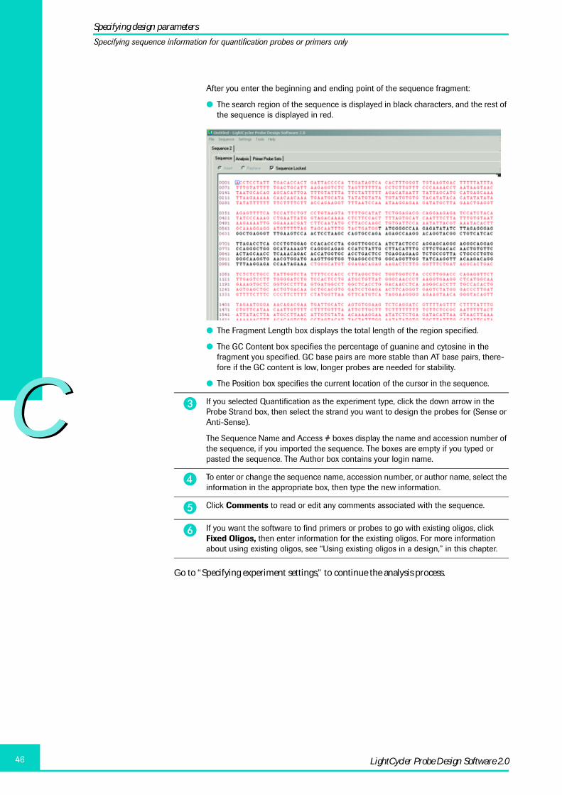
CC
LightCycler Probe Design Software 2.046
Go to “Specifying experiment settings,” to continue the analysis process.
After you enter the beginning and ending point of the sequence fragment:
� The search region of the sequence is displayed in black characters, and the rest of the sequence is displayed in red.
� The Fragment Length box displays the total length of the region specified.
� The GC Content box specifies the percentage of guanine and cytosine in the fragment you specified. GC base pairs are more stable than AT base pairs, there-fore if the GC content is low, longer probes are needed for stability.
� The Position box specifies the current location of the cursor in the sequence.
� If you selected Quantification as the experiment type, click the down arrow in the Probe Strand box, then select the strand you want to design the probes for (Sense or Anti-Sense).
The Sequence Name and Access # boxes display the name and accession number of the sequence, if you imported the sequence. The boxes are empty if you typed or pasted the sequence. The Author box contains your login name.
� To enter or change the sequence name, accession number, or author name, select the information in the appropriate box, then type the new information.
� Click Comments to read or edit any comments associated with the sequence.
� If you want the software to find primers or probes to go with existing oligos, click Fixed Oligos, then enter information for the existing oligos. For more information about using existing oligos, see “Using existing oligos in a design,” in this chapter.
Specifying design parameters
Specifying sequence information for quantification probes or primers only

CC
47Designing Primers and Probes
3.3 Specifying sequence information for mutation detection probes
For mutation detection, a probe must be designed to bind over the mutation site, whichconstrains the software search areas and probe design. The goal of good probe design formutation detection is to have difference in melting temperature between the probe/nor-mal-allele match and the probe/mutated-allele mismatch.
You can design SimpleProbe and HybProbe Probes for up to three mutation sites. Whenyou design the probes for multiple mutations, the software follows these rules:
� There must be at least one base between the mutation sites.
� If there are fewer than five bases between two mutation sites, one probe is designed tocover both sites. Each base over a mutation site can be designed to match either thewild type or the mutation.
� If there are between five and nine bases between two mutation sites, you can choosewhether to design one probe to cover both mutation sites or to design separate probesfor the sites.
� If there are more than nine bases between two mutation sites, two probes are auto-matically designed, one for each mutation site.
� The mutations must be located at least 50 bases from the beginning or end of thesequence fragment
� HybProbe Plus is always designed for two mutation sites, with a sensor probe overeach site and an anchor probe between.
You can specify whether you want the probe to match the wild type or the mutation andbe placed on the sense or the anti-sense strand. Or you can let the software automaticallyselect the combinations.
Specifying design parameters
Specifying sequence information for mutation detection probes

CC
LightCycler Probe Design Software 2.048
This section includes two procedures: one to specify sequence information for a singlemutation and the other to specify sequence information for multiple mutations.
To specify sequence information for a single mutation
Go to “Specifying experiment settings,” to continue the analysis process.
� (Optional) To renumber the sequence, enter a new number in the First Position field in the Sequence Information area.
� To specify the general region to be searched, enter the beginning position in the From box and the ending position in the Analyze To box.
After you enter the beginning and ending point of the region:
� The search region of the sequence is displayed in black characters, and the rest of the sequence is displayed in red (see “To specify sequence information” in Chapter C).
� The Fragment Length box displays the total length of the region specified.
� The GC Content box specifies the percentage of guanine and cytosine in the frag-ment you specified.
� The Position box specifies the current location of the cursor in the sequence.
� Type the position number of the mutation in the first Mutation Position box.
— Or —
Click in the first Mutation Position box, then double-click the base in the sequence display.
For mutation detection, the mutations must be located at least 50 bases from the beginning or end of the sequence fragment. Therefore, be sure to specify a fragment that begins at least 50 bases before the first mutation and ends at least 50 bases after the last mutation.
� In the Mutation Type box, click the down arrow, then select the type of mutation at this site, such as A to C.
� In the Mutation Match box, select one of the following methods to design the probe:
Selection Description
auto The software automatically determines whether the probe is designed to complement the wild type or the mutation and whether the probe covers the sense or anti-sense strand. The probe is designed to use the most destabilizing mismatch.
wt The probe is designed to complement the wild type. The software determines whether the probe covers the sense or anti-sense strand.
mut The probe is designed to complement the mutation. The software determines whether the probe covers the sense or anti-sense strand.
� To enter or change the sequence name, accession number, or author name, select the information in the appropriate box, then type the new information.
� Click Comments to read or edit any comments associated with the sequence.
� If you want the software to find primers or probes to go with existing oligos, click Fixed Oligos, then enter information for the existing oligos. For more information about using existing Oligos, see “Using existing oligos in a design,” in this chapter.
Specifying design parameters
Specifying sequence information for mutation detection probes

CC
49Designing Primers and Probes
To specify sequence information for multiple mutations
� (Optional) To renumber the sequence, enter a new number in the First Position field in the Sequence Information area.
� To specify the general region to be searched, enter the beginning position in the From box and the ending position in the Analyze To box.
After you enter the beginning and ending point of the region:
� The search region of the sequence is displayed in black characters, and the rest of the sequence is displayed in red.
� The Fragment Length box displays the total length of the region specified.
� The GC Content box specifies the percentage of guanine and cytosine in the fragment you specified.
� The Position box specifies the current location of the cursor in the sequence.
� Type the position number of each mutation in a Mutation Position box.
— Or —
Click in a Mutation Position box, then double-click the base in the sequence display.
Enter the mutations in the Mutation Position boxes in sequential order, from left to right. For example, if there are three mutations located on positions 501 and 520 and 545, the first box should display 501, the second 520 and the third 545.
� Respond to the messages as follows:
� If there are fewer than five bases between two mutation sites, a message states that one sensor probe will cover both sites. Click OK to clear the message.
� If there are between five and nine bases between two mutation sites, a message asks whether you want one sensor probe to cover both mutation sites. Click Yes or No.
If you click No, two probes will be designed, one for each site.
� If there are more than nine bases between two mutation sites, two sensor probes will automatically be designed, one for each mutation site. No message is displayed.
� In each Mutation Type box, click the down arrow, then select the type of mutation at this site, such as A to C.
� If multiple mutations are covered by separate probes, in the Mutation Match box for each mutation select one of the following methods:
Selection Description
auto The software automatically determines whether the probe isdesigned to complement the wild type or the mutation and whetherthe probe covers the sense or anti-sense strand. The probe isdesigned to use the most destabilizing mismatch to allow to distin-guish between a probe-allele match and a probe-allele mismatch.
wt The probe is designed to complement the wild type.
mut The probe is designed to complement the mutation.
The software automatically determines whether the sense or anti-sense strand is used.
Specifying design parameters
Specifying experiment settings

CC
LightCycler Probe Design Software 2.050
Go to “Specifying experiment settings,” below, to continue the analysis process.
3.4 Specifying experiment settings
The Experiment Settings area contains boxes used to specify experiment options, such asamplicon size and desired melting temperatures. The available options vary dependingon the type of primers and probes you are designing.
The following illustration shows the Experiment Settings area for a Quantification Hyb-Probe design.
� If multiple mutations are covered by the same probe, for the first mutation select one of the following methods in the Mutation Match box:
Selection Description
auto The probe is designed to maximize the difference in melting tem-perature (Tm) between a probe-allele match and a probe-allelemismatch, for all the mutations it covers. The software automati-cally determines whether the probe is designed to complement thewild type or the mutation and whether the probe covers the senseor anti-sense strand.
wt sense The probe is designed to bind to the sense strand and complementthe wild type.
wt anti-sense
The probe is designed to bind to the anti-sense strand and comple-ment the wild type.
mut sense The probe is designed to bind to the sense strand and complementthe mutation.
mut anti-sense
The probe is designed to bind to the anti-sense strand and comple-ment the mutation.
� If you did not select “auto” in the previous step, then for each additional mutation covered by the same probe, choose wt (wild type) or mut (mutation). (Auto applies to all mutation sites.)
To enter or change the sequence name, accession number, or author name, select the information in the appropriate box, then type the new information.
Click Comments to read or edit any comments associated with the sequence.
� If you want the software to find primers or probes to go with existing oligos, click Fixed Oligos, then enter information for the existing oligos. For more information about using existing oligos, see “Using existing oligos in a design” in this chapter.
� Select Sequence Locked to prevent accidental changes to the sequence.
Specifying design parameters
Specifying sequence information for mutation detection probes

CC
51Designing Primers and Probes
To specify experiment settings
� Enter the minimum size required for the amplicon in the Min Amplicon Size box and the maximum size in the Max Amplicon Size box.
� In the Primer Tm box, enter the desired melting temperature for the primers.
� In the Probe Tm boxes, enter the desired melting temperature for each probe.
The number of Probe Tm boxes depends on the type of probe and whether the probes are being designed for mutation detection or for quantification reactions.
� In the Dye Type field, click the down arrow, then select the dye type for the probe acceptor dye.
� (SimpleProbe only) In the Dye End box, click the down arrow, then select either 5’ or 3’.
Because guanine quenches dye, the software needs to know which end of the probe to assess for the presence of guanine. Probe designs with guanine at or near the dye end are penalized during scoring.
� To set additional experiment options, click Details.
The Settings dialog box opens with the Experiment Settings tab active. The tab lets you set additional options, including:
� The minimum and maximum size of all primers and probes
� The size of the gap between hybridization probes
� Primer and probe concentrations
� Individual melting temperatures for probes used with multiple mutations
The example below illustrates the Experiment Settings tab for a HybProbe design.
� Enter values as needed. When finished, click OK to close the Settings dialog box.
� Click Analyze to perform the preliminary analysis of the sequence.
The Analysis tab opens. For information about using the Analysis tab, see the next section.
Specifying design parameters
Specifying experiment settings

CC
LightCycler Probe Design Software 2.052
4. Analyzing and selecting the design region
After you click Analyze on the Sequence tab, the software displays the results of a prelim-inary analysis as a chart on the Analysis tab, as illustrated below. You can specify a region,indicated by a shaded area, that you want to use for the Primer Probe search.
When the Analysis tab is opened, the width of the shaded area is a multiple of the ampli-con size designated on the Sequence tab. You can drag the shaded area to any location onthe chart or resize it.
For mutation detection probes, a vertical line represents the location of each mutation.
Analyzing and selecting the design region

CC
53Designing Primers and Probes
To specify the region to analyze
� Select one of the following:
Extended ➔ Uses the entire fragment shown on the chart to encompass both the primer and the probe sites. Selecting Extended removes the shaded area.
Set ➔ Lets you specify one area, indicated by the shaded portion, to encompass both the primer and the probe sites.
Individual ➔ Lets you specify areas for the primers and probes separately. Selecting Individual replaces the shaded area with three shaded areas: blue (forward primer), green (probe), and pink (reverse primer).
� To redisplay the default analysis region and settings, click Reset.
� It is possible to specify one or more predefined oligos, called fixed oligos,and then let the software search for other oligos to go with the fixeddesigns. If you specify fixed oligos, the search regions on the Analysis tabare constrained by the location of the fixed oligos. For more informationabout using fixed primer and probes, see “Using existing oligos in a design,”in this chapter.
� If you specify Set or Individual, move the shaded area or areas to the locations you want to analyze. Move a shaded area in any of these ways:
� Click the shaded area then drag it to a new location.
� Click the border of an area, then drag the border to resize the area.
� Enter starting and ending positions for an area in the coordinate boxes below the graph.
You can specify only valid positions. For example, if using “Individual,” you must place the primer regions on either side of the probe region. If designing probes for muta-tion detection, you cannot change the probe region.
Analyzing and selecting the design region

CC
LightCycler Probe Design Software 2.054
This warning is also printed on the Report.
5. Viewing and saving results
The Primer Probe Sets tab displays the results of the final analysis. The designs aredisplayed in a ranked list.
You can limit the number of result sets displayed. You can also save the analysis to a file soit can be reopened later.
To view and save results
� Click Single Set Search.
The software searches for the optimal primer and probe locations in the designated area(s), then displays the ranked results on the Primer Probe Sets tab.
If you want to abort the search process before it is finished click Cancel during the search process. The LC PDS 2.0 will switch to the Primer Probe Sets screen displaying best primer probe sets (Limit Sets or Top 50 Sets) found up to the moment the search was stopped. A Warning message is displayed under the Result table.
� (Optional) To limit the number of result sets displayed, select one of the following options from the Settings menu:
� Top 50 sets ➔ Displays the top 50 results sets. Many of these sets have similar oligos.
� Limit sets ➔ Displays five result sets that provide the greatest diversity of oligos among the best-scoring result sets.
� To view design details, select a design from the result list.
The design is displayed below the list and is color-coded as follows:
� Blue = Primers
� Green = Probe1
� Red = Probe2
For more information, see the next section “How scores are displayed on the Primer Probe Sets tab.”
� To save the analysis, select Save from the File menu.
Viewing and saving results

CC
55Designing Primers and Probes
To reopen a previously saved analysis
See also the “Overview of File Formats” Table in the Appendix.
� Accept the default file name and location, or enter a new name and choose a new location, then click Save.
The file is saved with an .spd extension. The default file name is the name of the sequence. After you click Save, the software appends the date and time to the file name.
� To save the sequence itself:
� From the Sequence menu, select Export.
� Enter a new file name or keep the existing name.
� Navigate to a location to save the file, then click Save.
The sequence is saved as a text file (.txt extension).
� From the File menu, select Open.
� In the dialog box find and select the .spd file for the saved analysis, then click Open.
Saving the three steps serialized and separately in *.spd files (Sequence, pre-liminary Analysis and the final Primer Probe Sets analysis) gives you the most flexibility for later changes to individual steps.
Only the last created design will be stored as an *.spd file while the previous designs will be renamed in the archive folder as *.old files. To reopen those files select the file menu and choose Open and select file types *.old.
Viewing and saving results

CC
LightCycler Probe Design Software 2.056
5.1 How scores are displayed on the Primer Probe Sets tab
Various criteria are used to score the designs, including the complements within theprimer probe set and how close the primers and probes are to the specified melting tem-peratures. Some combinations are eliminated by default, for example, sets with primer/primer complements on a 3’ end.
An example of a Primer Probe Sets tab is shown below.
When you select a design from the result list, the design sequence is displayed below thelist and also in the text boxes in the lower left portion of the window.
The reaction conditions and sequence information you specified for the analysis aresummarized on the right.
For mutation detection probes, the position of the mutation limits the location of thesensor probe and by default the location of any associated anchor probe. Therefore,mutation detection primer probe sets usually have lower scores than quantificationprimer probe sets for the same amplicon.
Viewing and saving results
How scores are displayed on the Primer Probe Sets tab

CC
57Designing Primers and Probes
5.2 Viewing primers and probes within the sequence fragment
After you complete an analysis, you can view the primers and probes from a selecteddesign in their proper locations within the DNA sequence fragment.
To view a design within the DNA sequence fragment
6. Exporting a design as an XML file
You can export an oligo design to an XML “order” file that may be used for direct order-ing in the future. Meanwhile please refer to the Custom Probe Ordering section of theRoche Applied Science Web site to use the file to order the sequence.
To export a primer probe design to an order file
� On the Primer Probe Sets tab, select the design you want to view.
� From the Tools menu, select Show Alignment of Current Selection.
The sequence fragment from the Sequence tab is displayed in a dialog box.
� Scroll as necessary until you find the primers and probes in the sequence. Primer sequences are displayed in blue, Probes 1 are displayed in red, and Probes 2 are displayed in green.
� If necessary, adjust the display as follows:
� To make the window smaller or larger, click and drag the edge of the window.
� To see or hide line numbers, select or deselect Show Positions
� To make the lines longer or shorter, increase or decrease the value in Bases per Line.
� To display a different result set without closing the window, click the forward and backward arrows (<<, <, >, >>). The arrows display the first, previous, next, and last result sets from the Primer Probe Sets tab.
� To close the window, click the X in the upper right corner.
� From the Primer Probe Sets tab, select the design you want to order.
� From the Sequence menu, select Export, then select To Order.
� Choose a location to save the exported file.
� Enter a file name, then click Save.
The file is saved with an .xml extension.
Exporting a design as an XML file
Viewing primers and probes within the sequence fragment

CC
LightCycler Probe Design Software 2.058
7. Using existing oligos in a design
The LightCycler Probe Design Software 2.0 provides a “fixed oligos” feature that lets youdesign primers or probes to go with an existing oligo. The existing or fixed oligos can beeither from the LightCycler Probe Design Software 2.0 or from another source. The fol-lowing procedures explain how to use both types of fixed oligos.
To use a fixed oligo from the LightCycler Probe Design Software 2.0
� Open the .spd file (or .old file) containing the fixed oligo you want to use (File | Open), or perform the analysis to design a particular oligo you want to use.
� On the Primer Probe Sets tab, select the fixed oligo design.
� From the Tools menu, select Fixed Oligos – Import Current Selection.
The Fixed Oligos dialog box opens. Each oligo in the selected design is displayed in the dialog box, with information about the oligo in the boxes on the right.
� Click Clear under each oligo you do not want to use as a fixed oligo, leaving only those you do want to use.
� To use the complement of the probes, select Probes on Complement Strand.
� If needed, adjust the oligos as follows:
� To shift an oligo to the left or right on the strand, click the < and > buttons under the oligo.
� To add or delete a base on the left or right end of the oligo, use the + and – buttons under the oligo.
Note that the values in the 5’ Position, 3’ Position, and Length boxes change as you adjust the oligos.
Using existing oligos in a design

CC
59Designing Primers and Probes
� To delete or edit oligos:
� To delete all oligos, click Clear All.
� To edit an oligo, click in the oligo, then type or edit bases as needed.
If the edited oligo does not match the strand from which you imported the oligo, a warning message states that the strand does not exist in the sequence.
� To allow mismatched bases, select Allow Mismatched Oligos in the lower left of the dialog box. Mismatched oligos are displayed in red.
� If there are two mismatches in a row, or if the second base from the end is a mis-match, the software cannot calculate a melting temperature. You must enter a melting temperature manually in the Tm field.
� To use a sequence on the complement strand that is written from 3’ to 5’, select Complement Strand Oligos 3’ to 5’, then enter or paste the 3’ to 5’ sequence.
The software will find the 3’ to 5’ sequence in the order it is written. To reverse the sequence so it reads 5’ to 3’, paste in the 3’ to 5’ sequence, then deselect the option.
To see the fixed oligos in color on the Sequence tab after you close the dialog box, select Show Fixed Oligos on Sequence.
When finished, click OK.
� On the Sequence tab, analyze the sequence again to generate the oligos that corre-spond to the fixed oligos you specified.
The software uses the fixed oligo(s) to find optimal matching primers or probes. Note that the Fixed Oligos button on the Sequence tab lists the number of fixed oligos cur-rently being used. In the example below, one fixed oligo is being used.
On the Analysis tab, you cannot change the region that applies to a fixed oligo.
Using existing oligos in a design

CC
LightCycler Probe Design Software 2.060
To design primers or probes using a fixed oligo from another source
8. Printing windows and reports
You can print any of the windows in the LightCycler Probe Design Software 2.0 if youwant to keep a record of design parameters and sequence details.
After you complete an analysis and select a design, you can also generate a report con-taining the design details, including sequence information, experiment settings, andcomments (if any). To display or print a report, you must have Adobe Acrobat Readerversion 5 or 6 installed.
To print a LightCycler Probe Design Software 2.0 window
To print a report of a design
� In the LightCycler Probe Design Software 2.0, import or enter the sequence you want to analyze using the fixed oligos.
� From the Tools menu select Fixed Oligos, or click Fixed Oligos on the Sequence tab.
The Fixed Oligos dialog box opens, containing no data.
� Type or paste in the oligo sequences you want to use.
� Follow the previous procedure beginning at Step 5 to specify the fixed oligos.
� Display the window you want to print.
� Press Ctrl-P.
� Complete the primer probe analysis.
� On the Primer Probe Sets or Multiplex Sets tab, select the design.
Printing windows and reports

CC
61Designing Primers and Probes
� From the File menu, select Print Report.
A report settings dialog box opens.
� Select the following report options as needed, then click OK:
� Print Set Report ➔ Places an image of the result sequence at the top of the report, followed by a section containing statistics for each oligo in the set (such as position, length, and GC content).
� Print Comments ➔ Includes the comments associated with the DNA sequence (this option is inactive if there are no comments for the sequence).
� Remove Report After Printing ➔ The report will not be saved after printing.
� Ask for File Name ➔ You will be prompted to provide a name and location to save the report.
� Save Report to… ➔ The report will be saved to the specified default location. (If a report of the same name already exists at this location, this option says “Over-write report in….” Selecting the option will overwrite the existing report.)
� If you selected “Ask for File Name” in Step 4, browse to a location to save the report, enter a report file name (*.pdf), then click Save.
A “Printing progress” dialog box displays the progress of the report generation. (During this process, the report is being printed to an Adobe Acrobat PDF file, not to a printer.)
The PDF file containing the report opens. The following illustrations show the first and second pages of a typical report.
� Use the standard PDF controls to display each page of the report.
� Click Print to print the report.
� (Optional) To save a copy of the report to a different location from the one already specified, from the File menu, select Save As.
Click the X in the upper right corner of the PDF window to close the report.
Printing windows and reports

CC
LightCycler Probe Design Software 2.062
9. Performing a BLAST search
After you have performed an analysis and selected a candidate design, you can check theprimers against other genome sequences by performing a BLAST search. You must haveInternet access from your computer to perform a BLAST search.
Other search options are available on the NCBI BLAST Web site.
� Perform an analysis to design the primers and probes.
� On the Primer Probe Sets or Multiplex Sets tab, select the set you want to use for the BLAST search.
� From the Tools menu, select BLAST – Import Current Selection.
The BLAST dialog box opens. The Forward Primer and Reverse Primer boxes contain the primer sequences from the selected design.
The Delimiter box contains characters used to separate the forward and reverse primer sequences. Delimiters are needed because when the sequences are sub-mitted to the NCBI BLAST Web site, the forward and reverse primers are concate-nated and the combined string is used in the search. Without delimiters, the search could return a match for the “middle” portion of the combined string, which includes parts of both the forward and reverse primer. The presence of the delimiter charac-ters prevents such a match.
� In the Delimiters box, leave NN or enter some other delimiter character that is not in either the forward or reverse primer.
� In the Database box, select a BLAST database.
� In the Select From box, select organism.
� Click OK.
The request is sent to the NCBI BLAST Web site. When the request has been received, your Internet browser opens to the NCBI BLAST home page. The page displays results when the search is complete.
� Note the Request ID so you can retrieve the search results again, or use your browser’s commands to save the results.
Performing a BLAST search

DPerforming Advanced Tasks

DD
LightCycler Probe Design Software 2.064
1. Analyzing a design for cross-complementarities ......................................................................... 651.1 Opening the Cross Comp Tool and setting parameters ....................................................................... 65
1.1.1 Overview of the Cross Comp Tool main window ............................................................................ 661.2 Viewing and understanding analysis scores ........................................................................................... 681.3 Viewing details of cross-complementarities ............................................................................................ 70
1.3.1 Viewing all cross-complementarities in one alignment ............................................................... 721.4 Saving, printing, closing, and reopening a cross-complementarity analysis ............................... 731.5 Adding, deleting, and changing oligos in an analysis .......................................................................... 74
2. Designing primers and probes for a multiplex reaction ........................................................... 762.1 Overview of design steps ................................................................................................................................ 762.2 Importing sequences ........................................................................................................................................ 772.3 Specifying design parameters ....................................................................................................................... 772.4 Performing the initial multiplex search ...................................................................................................... 782.5 Adding new sequences to an existing multiplex search ..................................................................... 782.6 Refining the search ........................................................................................................................................... 79
3. Specifying experiment and reaction settings ................................................................................. 79
D Performing Advanced Tasks Page
Performing Advanced Tasks

DD
65Performing Advanced Tasks
Performing Advanced Tasks
This chapter explains how to perform advanced tasks using the LC PDS 2.0, includinghow to analyze a selected primer probe design for cross-complementarities and how todesign primers and probes for multiplex reactions.
1. Analyzing a design for cross-complementarities
You can use the LC PDS 2.0 Cross Comp Tool to view the cross-complementarities(including self-complementarities) between any two oligonucleotides (oligos) in aselected design. The tool displays all the cross-complementarities graphically, so you cansee the number, length, and location of the cross-complementarities at a glance. The toolalso scores the cross-complementarities according to either the number of cross-comple-mentarities or the stability of the cross-complementarities.
To use the tool, perform the following general steps:
After you set analysis parameters, you can:
� View the scores in the main window.
� View details of the cross-complementarities in the Complementarities window.
� Add, delete, or edit sequences if desired.
� Save the analysis and print windows and reports.
Each procedure is described in detail in this chapter.
1.1 Opening the Cross Comp Tool and setting parameters
This section describes how to open the tool, import a primer probe design from theLC PDS 2.0 Primer Probe Sets tab, and set analysis parameters.
You can add oligos manually to the Cross Comp Tool. For more information, see“Adding, deleting, and changing sequences in an analysis,” below.
� Open the tool and import or enter the oligos to analyze.
� Set analysis parameters and options.
Analyzing a design for cross-complementarities
Opening the Cross Comp Tool and setting parameters
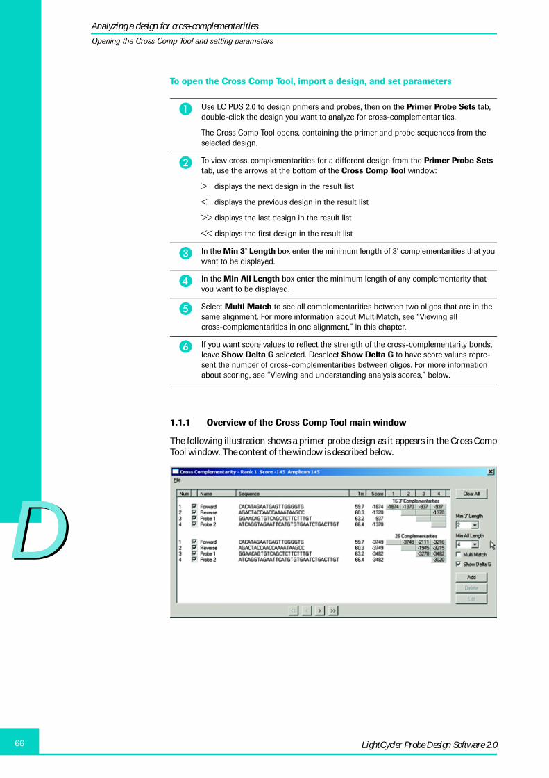
DD
LightCycler Probe Design Software 2.066
To open the Cross Comp Tool, import a design, and set parameters
1.1.1 Overview of the Cross Comp Tool main window
The following illustration shows a primer probe design as it appears in the Cross CompTool window. The content of the window is described below.
� Use LC PDS 2.0 to design primers and probes, then on the Primer Probe Sets tab, double-click the design you want to analyze for cross-complementarities.
The Cross Comp Tool opens, containing the primer and probe sequences from the selected design.
� To view cross-complementarities for a different design from the Primer Probe Sets tab, use the arrows at the bottom of the Cross Comp Tool window:
> displays the next design in the result list
< displays the previous design in the result list
>> displays the last design in the result list
<< displays the first design in the result list
� In the Min 3’ Length box enter the minimum length of 3’ complementarities that you want to be displayed.
� In the Min All Length box enter the minimum length of any complementarity that you want to be displayed.
� Select Multi Match to see all complementarities between two oligos that are in the same alignment. For more information about MultiMatch, see “Viewing all cross-complementarities in one alignment,” in this chapter.
� If you want score values to reflect the strength of the cross-complementarity bonds, leave Show Delta G selected. Deselect Show Delta G to have score values repre-sent the number of cross-complementarities between oligos. For more information about scoring, see “Viewing and understanding analysis scores,” below.
Analyzing a design for cross-complementarities
Opening the Cross Comp Tool and setting parameters

DD
67Performing Advanced Tasks
Oligo sequences
The main portion of the window displays the oligos for a particular design twice. The firstset of oligos is used to analyze the cross-complementarities with the 3’ ends of the prim-ers. The second set is used to analyze all cross-complementarities within the design. Eachset of oligos is numbered 1 – 4.
Information in each oligo row
Each row in each set of oligos also includes the following:
� A row number
� A check box used to include or exclude the oligo from the cross-complementarityanalysis
� The name of the primer or probe
� The bases in the oligo
� The melting temperature for the oligo as calculated by the software
� The score assigned to the oligo by the software
� Gray “detail” buttons used to view cross-complementarities in a separate Comple-mentarities window. Detail buttons are explained below.
Text above the buttons states the total number of complementarities between the primersand probes in each set.
Detail buttons
The detail buttons to the right of the oligos act as a matrix that links each oligo on thecurrent row with the oligo indicated by the column number above the button. For exam-ple, the button on row 1, column 4 links the Forward primer with Probe 2.
Notice that each row has one fewer detail button than the preceding row. This is becausethere is only one button for each possible combination of oligos. For example, there is nobutton under column 1 on row 4 because the same cross-complementarities can beviewed by clicking the button under column 4 on row 1.
Clicking a button displays a Complementarities window that displays the cross-comple-mentarities between the oligo on the current row and the oligo indicated by the columnnumber. For more information, see “Viewing details of cross-complementarities,” later inthis chapter.
Analyzing a design for cross-complementarities
Opening the Cross Comp Tool and setting parameters

DD
LightCycler Probe Design Software 2.068
Menu, buttons, and options
The Cross Comp Tool window includes a File menu you can use to open a previouslysaved cross-complementarity analysis, to save the current analysis, to print the windowor a report, and to reposition the window. For more information about using the Filemenu, see “Saving, printing, closing, and reopening a cross-complementarity analysis,”later in this chapter.
The window includes buttons used to clear all sequences from the window, and to add,delete, or edit individual sequences. For more information about the buttons, see “Add-ing, deleting, and changing sequences in an analysis,” later in this chapter.
Other options in the Cross Comp Tool window let you specify analysis parameters.
1.2 Viewing and understanding analysis scores
Oligos are assigned a cross-complementarity score. The total score for an oligo is dis-played in the Score column. Scores for each oligo pair are also displayed as numbers onthe gray detail buttons.
Scores are only calculated for cross –complementarities of at least the minimum size, asspecified in the “Min 3’ Length” box and the “Min All Length” box.
Two scoring methods are available:
� The Delta G method reflects the strength of the cross-complementarity bonds,expressed as a Delta G value. To use this method, select Show Delta G.
� The non-Delta G method reflects the number of cross-complementarities between oli-gos. To use this method, deselect Show Delta G.
How scores are calculated using Delta G
The Show Delta G option calculates the energy in the bond between cross-complementa-rities and expresses the bond as a negative number, the Delta G value. A larger negativenumber means a more stable bond.
When Show Delta G is selected, scores are displayed as follows:
� The Score column for each oligo displays the Delta G value of the strongest cross-com-plementarity (of at least the minimum size) between this oligo and any other oligo inthe analysis. For the first set of oligos in the window, this is the strongest 3’ cross-com-plementarity. For the second set, this is the strongest cross-complementarity of anykind.
� The gray detail buttons display the Delta G value of the strongest cross-complementa-rity (of at least the minimum size) between this oligo and the oligo represented by theheading number above the button. For the first set of oligos, this is the strongest 3’cross-complementarity. For the second set of oligos, this is the strongest cross-com-plementarity of any kind.
Analyzing a design for cross-complementarities
Viewing and understanding analysis scores

DD
69Performing Advanced Tasks
In the example above, there are no 3’ cross-complementarities of the minimum length(4 bases). Therefore, the values in the Score column are 0 for the first set of sequences,and there are no score labels on the detail buttons.
There are 23 total cross-complementarities of all kinds (having a minimum length of4 bases). The second set of oligos displays the Delta G values for the strongest cross-com-plementarity in the Score column and also on the detail buttons.
For example, the strongest cross-complementarity between the Forward primer and anyother oligo is –3279, as indicated in the value in the Score column on row 1. The stron-gest bond between the Forward primer and itself is –3278, as indicated by the value onthe first detail button on row 1.
How scores are calculated using number of cross-complementarities
If Show Delta G is not selected, the scores reflect the number of cross-complementarities(of the minimum length or greater).
The scores are displayed as follows:
� The Score column for each sequence indicates the total number of cross-complemen-tarities of at least the minimum size between this oligo and all other oligos in theanalysis.
� The detail buttons display scores as follows:
� A single number on a detail button without parentheses indicates the length of thelargest cross-complementarity (of at least the minimum size) between this oligoand the oligo referenced by the heading number above the button. It also indicatesthat there is only one cross-complementarity of this size.
� A number in parenthesis indicates how many of the largest cross-complementari-ties there are.
� No number on a button means there are no cross-complementarities (of at least theminimum size) between this oligo and the other oligo.
The example below shows scores when Show Delta G is not selected.
Analyzing a design for cross-complementarities
Viewing and understanding analysis scores

DD
LightCycler Probe Design Software 2.070
In the example above, there are no 3’ cross-complementarities of the minimum length(4 bases). Therefore, the values in the Score column are 0 for the first set of sequences,and there are no score labels on the detail buttons.
There are 23 cross-complementarities of all kinds (having a minimum length of 4 bases).The second set of oligos displays scores representing the number of largest cross-comple-mentarities. Looking at Row 1 in the second set of bases in the example above, the scoresindicate the following:
� The label on the first button, 4(3), indicates that the largest cross-complementaritybetween the Forward primer and itself is 4 bases long and there are 3 of them.
� The label on the second button, 4(2), indicates that the largest cross-complementaritybetween the Forward primer and the Reverse primer is 4 bases long and there are twoof them.
� The label on the third button, 4, indicates that the largest cross-complementaritybetween the Forward primer and Probe 1 is 4 bases long and there is one of them.
� The label on the fourth button, 4(2), indicates that the largest cross-complementaritybetween the Forward primer and Probe 2 is 4 bases long and there are two of them.
� The value in the Score column is 8, indicating that there are a total of 8 cross-complementarities (of at least 4 bases) between the Forward primer and all the otheroligos.
The labels on the detail buttons refer only to the largest cross-complementaritybetween two oligos. A large cross-complementarity includes multiple smallercross-complementarities. For example, a 5-base cross-complementarity includestwo 4-base complementarities. The large and small cross-complementarities areall included in the total score displayed in the Score column.
1.3 Viewing details of cross-complementarities
Clicking a detail button opens a Complementarities window that graphically displays thecross-complementarities between the two oligos represented by the button. You canselect more than one detail button at a time.
Analyzing a design for cross-complementarities
Viewing details of cross-complementarities

DD
71Performing Advanced Tasks
To display the Complementarities window, use any of the following procedures:
� To view complementarities for two oligos, click the detail button that represents thepair of oligos you want to analyze.
� To compare more than two oligos, hold down the Control key, then click the detailbuttons for all the oligo pairs you want to see. All combinations of the selected oligosare displayed in the Complementarities window.
� To see all primer-primer combinations, press Shift + Control and click any primer-primer button (for example, Row 1, Column 1).
� To see all primer probe combinations, press Shift + Control and click any primer probebutton (for example, Row 1, Column 3);
� To see all probe-probe combinations, press Shift + Control and click any probe-probebutton (for example, Row 3, Column 3).
The following illustration shows the Cross Comp Tool window and the Complementari-ties window. Complementarities are indicated by vertical lines. The bold lines indicatecross-complementarities of the minimum size or larger. In the example below, the win-dow displays cross-complementarities between the Forward primer and Probe 2 (the but-ton on row 1, column 4 is depressed).
You can move or resize the window, copy information from the window, or print thewindow.
Analyzing a design for cross-complementarities
Viewing details of cross-complementarities

DD
LightCycler Probe Design Software 2.072
To adjust the Complementarities window
� To resize the Complementarities window, click a side or corner of the window anddrag it to the desired size.
� To move the Complementarities window, click in the window’s title bar, then drag thewindow to the desired location.
� To return the Complementarities window to its default size and location, click the icon in the upper left corner of the Complementarities window, then select Reposition
Below Parent.
To copy and paste or to print the Complementarities window
� To copy and paste information from the window into another program:
� Highlight the information in the Complementarities window you want to copy,then press Ctrl-C to copy the information to the Clipboard.
� Open the destination file in the other program, then paste the information usingthe paste command appropriate for that program.
� To print the Complementarities window, resize the window so it displays the informa-tion you want to include, then press Ctrl-P or click the icon in the upper left cor-ner of the Complementarities window, then select Print Window.
1.3.1 Viewing all cross-complementarities in one alignment
The MultiMatch feature of the Cross Comp Tool collapses the sequence pairs in theComplementarities window so that all the cross-complementarities in a particular align-ment are shown together. This features makes it easy to see when a particular alignmentgenerates many cross-complementarities.
To use MultiMatch
� In the Cross Comp Tool window, select the MultiMatch option.
The following illustration shows two oligos as they appear in the Complementarities win-dow when MultiMatch is not selected. Notice that the pair of strands is repeated for eachof the bold cross-complementarities, even though the strands are in the same alignment.
Analyzing a design for cross-complementarities
Viewing details of cross-complementarities
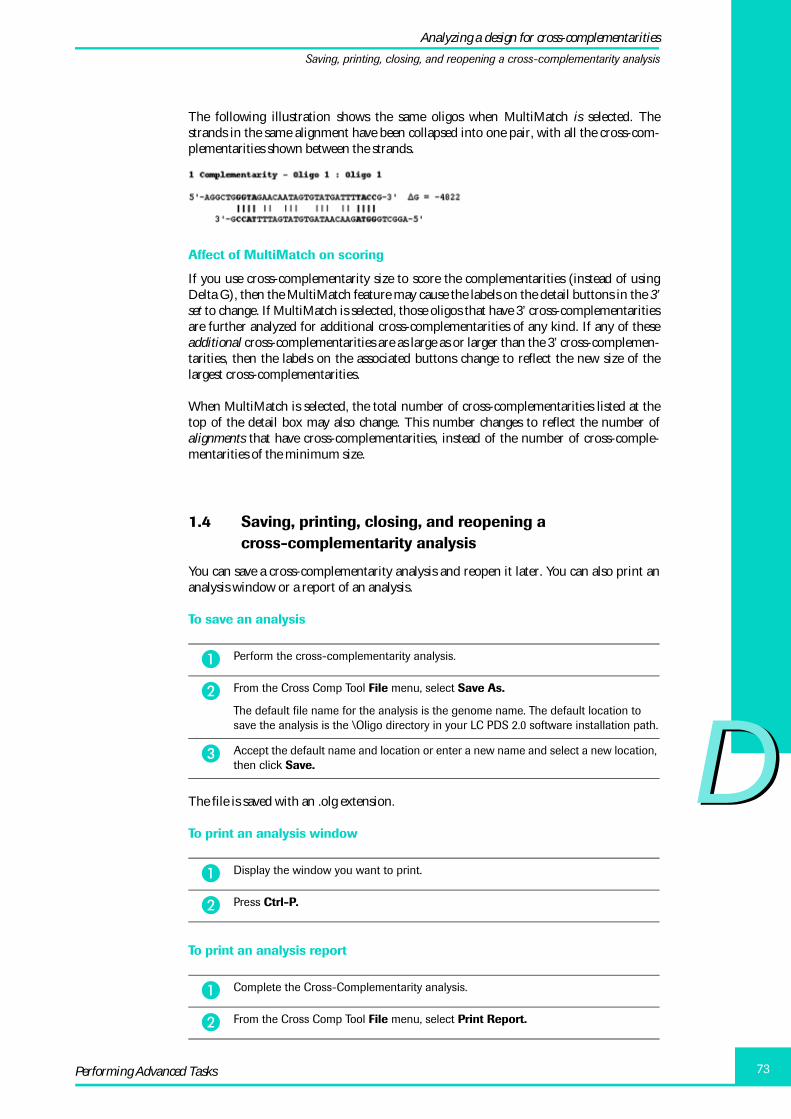
DD
73Performing Advanced Tasks
The following illustration shows the same oligos when MultiMatch is selected. Thestrands in the same alignment have been collapsed into one pair, with all the cross-com-plementarities shown between the strands.
Affect of MultiMatch on scoring
If you use cross-complementarity size to score the complementarities (instead of usingDelta G), then the MultiMatch feature may cause the labels on the detail buttons in the 3’set to change. If MultiMatch is selected, those oligos that have 3’ cross-complementaritiesare further analyzed for additional cross-complementarities of any kind. If any of theseadditional cross-complementarities are as large as or larger than the 3’ cross-complemen-tarities, then the labels on the associated buttons change to reflect the new size of thelargest cross-complementarities.
When MultiMatch is selected, the total number of cross-complementarities listed at thetop of the detail box may also change. This number changes to reflect the number ofalignments that have cross-complementarities, instead of the number of cross-comple-mentarities of the minimum size.
1.4 Saving, printing, closing, and reopening a cross-complementarity analysis
You can save a cross-complementarity analysis and reopen it later. You can also print ananalysis window or a report of an analysis.
To save an analysis
The file is saved with an .olg extension.
To print an analysis window
To print an analysis report
� Perform the cross-complementarity analysis.
� From the Cross Comp Tool File menu, select Save As.
The default file name for the analysis is the genome name. The default location to save the analysis is the \Oligo directory in your LC PDS 2.0 software installation path.
� Accept the default name and location or enter a new name and select a new location, then click Save.
� Display the window you want to print.
� Press Ctrl-P.
� Complete the Cross-Complementarity analysis.
� From the Cross Comp Tool File menu, select Print Report.
Analyzing a design for cross-complementarities
Saving, printing, closing, and reopening a cross-complementarity analysis

DD
LightCycler Probe Design Software 2.074
To close the Cross Comp Tool
To reopen a saved cross-complementarity analysis
1.5 Adding, deleting, and changing oligos in an analysis
You can add, delete, or edit individual oligos displayed in the Cross Comp Tool.
To add a new oligo to the analysis
The new oligo is added to the Cross Comp Tool window.
� From the File menu, select Exit, or click the X in the upper right corner of the window.
� From the LC PDS 2.0 Tools menu, select Cross Comp Tool.
If you have previously used the Cross Comp Tool during this software session, when you open the Tool, the previous cross-complementarity analysis is displayed.
� From the Tool’s File menu, select Open.
� Find and select the .olg file for the analysis you want to view, then click Open.
� View or edit the analysis as needed.
� From the File menu, select Save.
� In the Cross Comp Tool, click Add.
An Edit Sequence dialog box opens.
� In the Name box, enter the name of the oligo (Forward, Reverse, Probe 1, or Probe 2 or any name you choose).
� In the Sequence box, type or paste the sequence.
� If this is a primer, select Is Primer.
� If the oligo is a probe, but you want to place the probe on the opposite strand, select Complement Strand.
� Click OK.
Analyzing a design for cross-complementarities
Adding, deleting, and changing oligos in an analysis

DD
75Performing Advanced Tasks
To add a design to a previously saved analysis
After you design one set of primers and probes, you can add the selected design to a pre-viously saved cross-complementarity analysis to view cross-complementarities betweenthe two designs. For example, you might want to do this if you are planning to use thetwo sets of primers and probes in a multiplex reaction.
To delete a primer or probe
To edit a sequence
The changes are applied to the oligo in the Cross Comp Tool window, so you can analyzethe modified sequence for cross-complementarities.
After you edit an oligo sequence, a tilde (~) is displayed in front of the calculated Tm toindicate that the melting temperature is now an estimate. The software cannot determinethe exact melting temperature of an edited oligo sequence.
� Design the first primer probe set, then perform a cross-complementarity analysis on the set and save the results.
� Design the next primer probe set (the set you want to analyze for cross-complemen-tarities with the first set); leave the LC PDS 2.0 Primer Probe Sets tab selected.
� Open the Cross Comp Tool.
� From the File menu, select Open.
� Find and select the previously saved cross-complementarity analysis, then click Open.
The saved analysis is displayed in the Cross Comp Tool.
� Close the Cross Comp Tool.
Even though the tool is closed, it “remembers” the analysis that was just displayed.
� On the Primer Probe Sets tab, select the primer probe design you want to analyze with the previously saved cross-comp analysis.
� From the Tools menu, select Cross Comp Tool – Add Current Selection.
The Cross Comp Tool opens, displaying the previously saved analysis (because it was the last analysis displayed) and also the primer and probe design currently selected on the Primer Probe Sets tab.
View the cross-complementarities among the oligos, as described in the previous sections.
� In the Cross Comp Tool, deselect the check box next to an oligo to remove it from the current analysis of cross-complementarities.
— Or —
To remove the oligo from the Cross-Comp Tool completely, click Delete. The oligo is deleted from the tool window.
� In the Cross Comp Tool, select the oligo you want to change, then click Edit.
The Edit Sequence dialog box opens, containing the oligo sequence.
� Change values as necessary.
If the sequence was imported from the Primer Probe Sets tab of the Probe Design window, you can edit only the sequence name.
� Click OK.
Analyzing a design for cross-complementarities
Adding, deleting, and changing oligos in an analysis

DD
LightCycler Probe Design Software 2.076
2. Designing primers and probes for a multiplex reaction
A multiplex reaction is one in which multiple DNA sequences are analyzed in the samecapillary tube. You can design oligos for two kinds of multiplex reactions:
� A standard multiplex reaction. In this case, you must design primers and probes foreach DNA target and then label each probe with a different dye, which will be mea-sured in different fluorimeter channel in the PCR instrument. After amplification, thepresence of a DNA product is indicated by the presence of an amplification curve inthat product’s fluorescence channel. With LC PDS 2.0 you can design primer andprobes for up to 4 different DNA targets with 4 different color dyes (610, 640, 670 and705 nm) in only one reaction.
� An amplicon multiplexing reaction. In this case, you design only the primers neededto amplify each DNA target. Sybr Green I is used to indicate the presence of DNA. TheDNA targets must have distinctly different melting temperatures. The amplificationreaction is followed by a melt; the presence of DNA product is indicated by the pres-ence of different melting temperatures in the fluorescence data.
2.1 Overview of design steps
To design primers and probes for a multiplex reaction, you must perform the followinggeneral steps. The steps are described in detail in the rest of this section.
� Import each target DNA sequence to be used in the multiplex reaction.
� Specify design parameters for each DNA target.
It is recommended to use the LightCycler Multiplex DNA Master HybProbe for best performance.
� Perform the initial search.
� Refine the search.
Designing primers and probes for a multiplex reaction
Overview of design steps

DD
77Performing Advanced Tasks
2.2 Importing sequences
Only the sequences to be used in the multiplex reaction must be loaded into thesoftware window. Delete any sequences that are not to be included in the multi-plex reaction.
To import multiple sequences
2.3 Specifying design parameters
You must specify the same design parameters for a multiplex reaction as you do for anon-multiplex reaction.
To specify design parameters
� To delete a sequence that is not used in the multiplex reaction:
� Select the Design tab containing the sequence name, then from the Sequence menu, select Delete.
You are prompted to confirm the deletion.
� Click OK.
� Enter or import a sequence for the multiplex reaction. For instructions, see the section “Entering a DNA sequence,” in Chapter C, above.
� If a sequence is already open in the software, you are asked whether you want to replace the existing sequence. Click No.
� Repeat Steps 2 and 3 to add additional sequences.
Be sure each Design tab contains a sequence. Do not leave any empty tabs in the window, because the software includes the empty tabs when it searches the sequences, causing an error.
� Select the Sequence tab for the first sequence included in the multiplex reaction.
� Specify values in the Experiment Type, Sequence Information, and Experiment Settings areas of the tab as you would for any non-multiplex reaction.
For more information about all the settings, see “Specifying design parameters,” in Chapter B.
� Repeat Steps 1 and 2 for each remaining sequence in the reaction.
� For a standard multiplex reaction, you must either specify different dye typesfor each sequence, or you must specify probe melting temperatures that areat least 5°C apart. The melting temperatures of probes with dyes of adjacentwavelength should differ at least 2°C. Otherwise the software displays anerror.
� For an amplicon multiplexing design, you must specify Amplicon Multiplexingfor each sequence.
Designing primers and probes for a multiplex reaction
Specifying design parameters

DD
LightCycler Probe Design Software 2.078
2.4 Performing the initial multiplex search
To perform the initial search and view results
2.5 Adding new sequences to an existing multiplex search
You cannot import additional sequences to an existing multiplex search (forexample to increase from 2-x to 3-x multiplexing). To do this, start with a newdesign, import the previously saved *.spd file first (two sequences) and thenimport the sequence you want to be included for the 3x-plexing.
� On the Sequence tab for the first sequence included in the reaction, click Analyze.
The Analysis tab opens
� On the Analysis tab, define the search region for primer and probe sites. Do not click Single Set Search.
� Repeat Steps 1 and 2 for each remaining sequence in the reaction.
� After all search regions are defined, from the Tools menu, select Multiplex Initial Search.
Status messages report the progress of the search.
If you clicked Single Set Search on the Analysis tab for any of the sequences, a message asks whether you want to delete the single set searches. Click Yes to continue the multiplex search.
� View results on the Multiplex Sets tab.
Results are ordered from highest (best) to lowest.
� To view details of a set, select the set from the result list.
Details are displayed in the pane below the list. The type of information displayed on the window is identical to that displayed for a non-multiplex reaction. For more infor-mation, see “Viewing and saving results” in Chapter C.
Designing primers and probes for a multiplex reaction
Performing the initial multiplex search

DD
79Performing Advanced Tasks
2.6 Refining the search
After you complete an initial search for multiplex oligos, you can perform a refinedsearch that searches the bases on either side of the primers in a selected design.
To perform a refined search
3. Specifying experiment and reaction settings
You can change the experiment settings and reaction conditions for the current analysis,or you can change the default settings that are applied automatically when you import orenter a new sequence. When you specify default settings, you can specify defaults for eachtype of experiment (Quantification, Mutation Detection, and so on).
To change settings for the current analysis
To change default settings
� On the Multiplex Sets tab, select the primer probe set you want to use as the basis for the refined search.
You may want to perform a cross-complementarity analysis to help you choose a set. For more information, see “Analyzing a design for cross-complementarities” in Chapter D.
� From the Tools menu, select Multiplex Refined Search.
� View results on the Multiplex Sets tab.
� From the Settings menu, select Current Settings.
The Settings dialog box opens. The values reflect the settings from the main Probe Design window and apply only to the current analysis.
� Modify the values on each tab as needed.
� When finished, click OK.
� From the Settings menu, select Default Settings.
The Default Settings dialog box opens. The options you set here become defaults that are applied whenever you enter or import a new sequence.
� Select an experiment type (Quantification, Mutation Detection, Primers Only, or Amplicon Multiplexing).
Additional fields are displayed, depending on your selection.
� Set the values you want for the currently selected experiment type.
� Repeat Steps 2 and 3 to specify default values for the other experiment types.
Specifying experiment and reaction settings
Refining the search

DD
LightCycler Probe Design Software 2.080
� To set default reaction conditions for all experiment types, select the Reaction Con-ditions tab, then select, add, or edit reaction conditions, as follows:
To edit a magnesium concentration of an existing buffer, select the buffer name, click Edit, modify the magnesium concentration, then click OK. The modified buffer is added to the list as an additional buffer.
To create a new buffer, click Add, enter information to define the new type, then click OK.
To delete a buffer you have added, select the desired buffer, then click Delete.
You cannot delete Roche Standard buffer.
� When you are satisfied with all the default experiment settings and reaction conditions, click OK.
Specifying experiment and reaction settings

Appendix

DD
LightCycler Probe Design Software 2.082
1. Uninstalling LC PDS 2.0 under Windows XP professional ...................................................... 83
2. Optimizing Primer Probe Sets designed with the LightCycler 2.0 ...................................... 84
3. Recommendation for applying asymmetric PCR .......................................................................... 86
4. Troubleshooting ............................................................................................................................................... 87
5. Overview of file formats .............................................................................................................................. 89
6. Literature ............................................................................................................................................................. 90
7. Copyright notice and disclaimers ......................................................................................................... 91
8. Trademarks ......................................................................................................................................................... 94
Appendix Page

83Appendix
Appendix
1. Uninstalling LC PDS 2.0 under Windows XP professional
It is recommended to remove existing versions of LC PDS before installing future ver-sions. Removing the previous version of the software does not delete any existing primerprobe designs such as *.spd and *.old files.
To uninstall a previous version of the software
� Insert the new LightCycler Probe Design Software 2.0 CD in the CD-ROM drive.
If a previous version of the software is installed, the following window opens.
If the window above is not displayed, then a previous version of the software is not installed on your computer. To install the new software, follow the proce-dure, “Installing the new software version” in Chapter A.
� Select Remove, then click Next.
A message asks you to confirm removing the application and all its components.
� Click OK.
The software is removed, then a Maintenance Complete window opens.
� Click Finish.
Uninstalling LC PDS 2.0 under Windows XP professional

LightCycler Probe Design Software 2.084
2. Optimizing Primer Probe Sets designed with the LC PDS 2.0
LC-PDS 2.0 greatly simplifies the design of LightCycler Probe reactions. For multiplexingassays it has been evaluated that it is possible just to start with the multiplex reaction.Pre-testings with monoplex assays is not longer a need. But PCR is a complex process andfor any given experiment only some of the important factors can be known. In practicethis means that once primer probe sets have been designed with the software, it isstrongly advised that a simple protocol be run to find the most robust conditions for thereaction.
Traditionally, a single bright band on an agarose gel is a good indicator of an optimizedPCR reaction. On the LightCycler, cycle threshold (crossing point) values as well as end-point fluorescence levels define an optimized reaction. A more efficient reaction will havea lower cycle threshold value and higher end-point fluorescence.
Optimization of LightCycler reactions requires only a few steps that are described below.There are four critical variables to optimize:
➔ The Annealing Temperature
In every PCR reaction there is a competition for hybridization between the primers andthe complementary target strand. Early in the reactions the primers are helped by massaction, as they are far more concentrated than the target strands. But as the reaction con-tinues this advantage is diminished.
The maximum rate of primer annealing occurs at about 5°C below the Tm of the primer.This is the temperature where the primer should compete most successfully with theproduct and is the best place to start when optimizing the reaction.
The Tm can be found on the LCPD report. The best guess annealing temperature is deter-mined by subtracting 5 degrees from the melting temperature of the lowest meltingprimer. Begin with a 10 second annealing time.
Example: For a primer set with Tm´s of 61°C and 60oC, the best guess annealing tempera-ture is 55°C.
➔ The Product Extension Time
The extension temperature should almost always be 72°C; this is the optimal temperaturefor Taq DNA polymerase. At this temperature Taq polymerase will add about 100 nucle-otides per second. A safe extension time (in seconds) can be determined by dividing theproduct length by 25. The length of your product can also be found on the primer/probereport sheet.
Example: For a 377 base pair product Extension Time = 400/25 = 16 seconds.
➔ The Denaturation time
When using the LightCycler FastStart DNA Master HybProbe and the LightCycler Multi-plex DNA Master HybProbe, a 10-minute hold should precede the cycling protocol witha 10 second hold at the denaturation step of each cycle. This is required to activate thepolymerase.
Optimizing Primer Probe Sets designed with the LC PDS 2.0

85Appendix
➔ Mg 2+ Concentration
Magnesium concentration is important in the PCR reaction for two reasons: First, mag-nesium stabilizes DNA duplexes, and second the magnesium aids the enzymatic activityof Taq polymerase.
The magnesium concentration used in probe design by LC PDS 2.0 will often be the opti-mal concentration. However, since magnesium is so important to the reaction, it is rec-ommended to run the best guess conditions discussed above with 2, 3, 4 and 5 mM(final) magnesium to determine the optimum concentration.
If the magnesium concentration is too high the reaction will not be stringent enough.Primer dimers and other non-specific products will form. If magnesium is too low, thereaction will not perform as well because the primers will not bind efficiently to the tem-plate strands. At extremely low magnesium the deoxynucleotides will bind up all themagnesium and the enzyme will not be able to perform at its best. By the same token ifthe annealing temperature is too low, it creates an environment suitable for primerdimers. If the annealing temperature is too high it is too stringent, even for perfectlymatched primers to anneal.
The figure (see above) gives an overview of the input of magnesium concentration andannealing temperature on stringency.
Optimizing Primer Probe Sets designed with the LC PDS 2.0

LightCycler Probe Design Software 2.086
3. Recommendation for applying asymmetric PCR
An additional method that may lead to the improvement of certain reactions is asymmet-ric amplification. Using an asymmetric primer ratio results in preferential amplificationof one strand. If the favoured strand is the one that binds to the probes, asymmetricamplification can lead to an improvement of the fluorescence signal, especially for longamplicons.
Quantification
Asymmetric amplification may help reduce the decline in the fluorescent plateau (hookeffect) that is sometimes seen with HybProbe Probes. Depending on base compositionand length of an amplicon its strands may tend to anneal faster than the HybProbeProbes have the opportunity to bind to their target sites. This is also avoided by favouringthe production of one strand. The drawback of asymmetric amplification is a reducedPCR efficiency because the reaction shifts from exponential to linear amplification as oneof the primers becomes limiting.
If no fluorescent signal is obtained in the PCR reaction containing HybProbe Probes, andone is confident that the primers are successfully amplifying DNA, the problem might becaused by competition between probe-target hybridization and target-target hybridiza-tion that results in out-competition of the probes by the complementary strand of thetarget DNA. This can be overcome by skewing the primer concentration in the reactionto favor the formation of the DNA strand that the probes bind to.
In this case, the concentration of the primer that produces the strand com-plementary to the probes is raised 2 to 5 fold (up to 50 fold for SimpleProbeProbes) over the other primer. No other reaction conditions should bechanged.
This simple change can sometimes transform what appears to be a failure of the reactioninto a well-defined amplification.
Melting Curve Analysis
Using asymmetric PCR, fluorescence signals and melting peaks can be improved.
Forward Primer (µM) Reversed Primer (µM)100% 0.5 0.580% 0.4 0.560% 0.3 0.540% 0.2 0.5H2O 0.1 0.5
Recommendation for applying asymmetric PCR

87Appendix
4. Troubleshooting
Overlapping oligos
For very small amplicons sizes and for mutation positions at the very ends of sequences itmay occur that sequences for primers and probes overlap. If so, a notification field indi-cating a warning, will be displayed in the results TAB and Print Report.
If possible you should avoid those sets. If inescapable try to enlarge the search area of thesequence. A different approach could be: Select only the sets with minimal overlap for thesame strand and avoid primer probe overlappings on different strands that may lead toprimer extension.
Fixed Oligos
Differences in Tm
If you use tested existing oligos (fixed Oligos) and get a bad score during the analysis,check whether the Tm’s you defined in the settings and the Tm’s of the fixed oligos matchclosely. If not, the chance is high that this is the cause for the bad score.
This applies also for comparison studies with previous Software versions such as LC PDSversion 1.0 and LC PDS 2.0.
Delta G
The delta G value allows better interpretation of cross-complementarities. Besides count-ing the numbers of complementary bases, it discriminates between weak and strongbinding of TA or GC.
The following example compares four bp overlaps of primers with high stability (GC),medium and lower stability (AT)
3' Complementarity - strong binding:
5'-AAAGGCC-3' �G = -4411 ||||
3'-CCGGAAA-5'
3' Complementarity - medium binding:
5'-AAAGATC-3' �G = -2011 ||||
3'-CTAGAAA-5'
3' Complementarity - weak binding:
5'-AAATTAA-3' �G = -1112 ||||
3'-AATTAAA-5'
Delta G’s less than -3000 should be avoided.
Troubleshooting
LightCycler Probe Design Software 2.088
Optimizing designs
If you get high yield of amplicon by gel analysis but suboptimal signal / Tm peak youmight improve the performance by starting a new design for the same primers and switchthe probe binding site to the complementary strand.
Adding new sequences to an existing multiplex search
You cannot import additional sequences to an existing multiplex search (for example toincrease from 2-x to 3-x multiplexing). To do this, start with a new design, import thepreviously saved *.spd file first (two sequences) and then import the sequence you wantto be included for the 3x-plexing.
Scores
The principle of scoring is to add penalties (negative points).As every suboptimal motif in the sequence gets penalized the scores get more negative.The best oligo score that can be reached is “zero”.
Sequence names / Print Report
Please avoid potential errors during creation of Print Reports by using letters only forsequence names.
Not allowed are „ / \ > : < * ? | “
Troubleshooting

89Appendix
5. Overview of file formats
This table explains file extensions used in the LC PDS versions 1.0 and 2.0.
Explanation of File Formats in LC PDS 2.0
*.spd Result of a design with LC PDS 2.0.
*.lpd Result of a design with LC PDS 1.0.
If you import a *.lpd file under LC PDS 2.0 only the sequence information ispresent.
*.old Designs saved as *.spd files (LC PDS 2.0) such as Sequence, Analysis orPrimer Probe Sets (created during the design process with identical designfile names) are being saved as *.old files in the ‘Archive’ Folder (renamed*.spd files). The second part of the *.old file name indicates the time of cre-ation. This information is helpful to follow up on the history of designs. Onlythe last created design will be stored as an *.spd file.
*.txt Text file formats of Sequences.
Please use the command ‘Import’ in the Sequence menu for sequencesgenerated in GenBank, EMBL and FASTA formats.
*.olg Result of a cross-complementarity analysis.
*.XML Flexible format to exchange information of primer probes sequences forfuture order options via Internet.
*.pdf File format of the Design Print Report.
Overview of file formats

LightCycler Probe Design Software 2.090
6. Literature
� J Wittwer, C.T., Herrmann, M.G., Moss, A.A., Rasmussen,R.P. (1997): Continous Fluorescence Monitoringof Rapid Cycle DNA Amplification. BioTechniques 22: 130 – 138.
� J Wittwer, C.T., Ririe, K.M., Andrew, R.V., David, D.A., Gundry, R.A., Balis, U.J. (1997): The LightCycler™: A Microvolume Multisample Fluorimeter with Rapid Temperature Control. BioTechniques 22: 176 – 181.
� J SantaLucia, J., Jr. (1998): A Unified View of Polymer, Dumbbell, and Oligonucle-otide DNA Nearest-Neighbor Thermodynamics. Proc. Natl. Acad. Sci. USA 95: 1460 – 1465.
� J Peyret, N., Seneviratne, P. A., Allawi, H. T., SantaLucia, J., Jr. (1999): Nearest-Neighbor Thermodynamics and NMR of DNA Sequences with Internal A-A, C-C, G-G, and T-T Mismatches. Biochemistry 38, 3468 – 3477.
� J Bernard P.S., Wittwer C.T. (2000): Homogeneous Amplification and Variant Detection by Fluorescent Hybridization Probes. Clinical Chemistry 46,147 – 148
� J de Silva, D., Wittwer, C.T. (2000): Monitoring Hybridization during Polymerase Chain Reaction. Journal of Chromatography B, 741 3 – 13
� J Wittwer, C.T. (2001): Rapid Real-Time PCR: Methods and Applications from: Rapid Cycle Real-Time PCR: Methods and Applications, Springer Verlag, 1
� J Bernard, S.B., Reiser, A., Pritham, G.H. (2001): Mutation Detection by Fluorescent Hybridization Probe Melting Curves from: Rapid Cycle Real-Time PCR: Methods and Applications, Springer Verlag, 11
Literature
91Appendix
7. Copyright notice and disclaimers
LightCycler Probe Design Software 2.0
NOTICE TO USER: THIS IS A BINDING CONTRACT. PLEASE READ IT CAREFULLY.BY INSTALLING, READING INTO MEMORY OR EXECUTING THIS SOFTWARE,YOU ACCEPT AND AGREE TO BE BOUND BY THESE TERMS AND CONDITIONS.
For purposes of these Terms and Conditions, the term “You” refers, individually and col-lectively, to (1) the individual user who installs, reads into memory and/or executes thisSoftware and (2) if such individual user is employed by or a representative or agent of alegal entity, such legal entity. You hereby covenant and agree with, and for the benefit of,Roche Diagnostic GmbH, Mannheim (“RDG”), as follows:
§ 1 Ownership of the Software
1.1 This SOFTWARE and the accompanying written materials are owned by IdahoTechnology, Inc., an Idaho corporation (“IT”), and exclusively licensed by IT to RDG.The Software is protected by copyright laws and international copyright treaties, as wellas other intellectual property laws and treaties. Except for the rights expressly provided bythese Terms and Conditions, You stipulate and agree that neither RDG nor IT grants byimplication, estoppel, or otherwise, any rights or licenses in, to or under the Software orany related proprietary rights under applicable patent, trade secret, copyright or otherlaws, rules or regulations.
§ 2 Grant Of License
2.1 RDG grants You the non-exclusive, royalty-free, worldwide right and license to (a)install and use one copy of the SOFTWARE on a single computer system or (b) in thecase of a multi-user or networked system which permits access to the SOFTWARE bymore than person at the same time, install and use the SOFTWARE on a single networkfile server or other storage device, provided that You have obtained a License for NetworkStation from RDG for the number of stations or computer terminals which may access orexecute the SOFTWARE from such file server or other storage device (the “LICENSE”).
2.2 The LICENSE does not permit You to copy the SOFTWARE, except that You maymake one copy of the SOFTWARE in machine readable form solely for backup purposes,provided you reproduce the copyright notice(s) and any proprietary legends. You maynot copy the written materials which accompany the SOFTWARE.
§ 3 Restrictions on Use and Transfer
3.1 You may not distribute the reports generated by the SOFTWARE in exchange forany compensation, revenue or any other material exchange without express written per-mission from RDG, which shall be granted at the sole discretion of RDG, subject to amutually amicable business arrangement between RDG and you.
3.2 You shall maintain the SOFTWARE and all proprietary rights as confidential andproprietary with at least the same degree of care that You use to protect your own confi-dential and proprietary information, but no less than a reasonable degree of care underthe circumstances. You shall take all steps necessary to ensure that all persons havingaccess through it to the SOFTWARE agree to, and observe and perform, the provisions ofthese Terms and Conditions.
Copyright notice and disclaimers

LightCycler Probe Design Software 2.092
3.3 You may permanently transfer your original copy of the SOFTWARE and accompa-nying written materials (including the most recent update and all prior versions) pro-vided (1) You retain no copies and (2) the transferee receives these Terms and ConditionsAND agrees in writing to be bound by its terms. Such a transfer terminates the LICENSEas to You and substitutes the transferee in your place.
3.4. You may not sell, transfer, assign, lease, loan, rent, sublicense, reproduce, duplicateor distribute the SOFTWARE in whole or in part; except as stated in the preceding para-graph. The SOFTWARE contains trade secrets and in order to protect them, You may notdecompile, reverse engineer, disassemble, or otherwise reduce the SOFTWARE to itssource code or other preferred human-perceivable form. YOU MAY NOT MODIFY,ADAPT, TRANSLATE, RESELL FOR PROFIT, DISTRIBUTE, NETWORK OR CREATEDERIVATIVE WORKS BASED UPON THE SOFTWARE OR ANY PART THEREOF.
§ 4 Limited Warranty
4.1. THIS SOFTWARE IS PROVIDED "AS IS" AND WITHOUT ANY WARRANTIESOF ANY KIND OR NATURE. THE ENTIRE RISK AS TO THE QUALITY AND PER-FORMANCE OF THE SOFTWARE IS BORNE BY YOU. ANY AND ALL EXPRESS ORIMPLIED WARRANTIES, INCLUDING, BUT NOT LIMITED TO, THE IMPLIEDWARRANTIES OF MERCHANTABILITY, NON-INFRINGEMENT, INTEROPERABIL-ITY, AND FITNESS FOR A PARTICULAR PURPOSE ARE DISCLAIMED. NO ORALOR WRITTEN OR ADVICE GIVEN BY THE COMPANY, ITS AGENTS OR EMPLOY-EES SHALL CREATE Any WARRANTY.
4.2 IN NO EVENT SHALL RDG OR IT BE LIABLE FOR ANY DIRECT, INDIRECT,INCIDENTAL, SPECIAL, EXEMPLARY, OR CONSEQUENTIAL DAMAGES (INCLUD-ING, BUT NOT LIMITED TO, PROCUREMENT OF SUBSTITUTE GOODS OR SER-VICES; LOSS OF USE, DATA, OR PROFITS; OR BUSINESS INTERRUPTION),HOWEVER CAUSED AND REGARDLESS OF THEORY OF LIABILITY, WHETHER INCONTRACT, STRICT LIABILITY, TORT (INCLUDING NEGLIGENCE) OR OTHER-WISE ARISING IN ANY WAY OUT OF THE USE OF THIS SOFTWARE, EVEN IFADVISED OF THE POSSIBILITY OF SUCH DAMAGE.
4.3 ANY LIABILITY OF RDG OR IT ARISING FROM OR RELATED TO THE USE,POSSESSION OR OPERATION OF THE SOFTWARE IS EXPRESSLY LIMITED TOTHE GREATER OF (a) THE MONETARY FEES PAID BY YOU TO RDG FOR THESOFTWARE OR (b) U.S. $100.00. YOUR SOLE REMEDY IN ANY DISPUTE REGARD-ING THE SOFTWARE UNDER THESE TERMS AND CONDITIONS SHALL BE TOSEEK RECOVERY OF SUCH AMOUNTS, UPON THE PAYMENT OF WHICH RDGAND IT SHALL BE AUTOMATICALLY RELEASED FROM AND DISCHARGED OFALL FURTHER OBLIGATIONS AND LIABILITY TO YOU.
4.5 The remedies provided in this Section 4 shall be your sole and exclusive availableremedy(ies) and You stipulate and agree that the exclusive remedy(ies) herein providedfully satisfy their essential and intended purposes (more particularly, You stipulate andagree that the exclusive remedy(ies) provided herein will, despite the difficulties inherentin determining actual damages which You might incur or suffer in the future, providelegally adequate monetary and other compensation to You).
§5 Miscellaneous Provisions
5.1 The failure of either party to take any action under these Terms and Conditions, orthe waiver of a breach of these Terms and Conditions, shall not affect that party's rights torequire performance hereunder or constitute a waiver of any subsequent breach. Awaiver to be valid shall be in writing, but need not be supported by consideration.
Copyright notice and disclaimers

93Appendix
5.2 These Terms and Conditions may not be altered, modified, amended or changed, inwhole or in part, except by a writing executed by the parties.
5.3 These Terms and Conditions shall be governed by the laws of the State of Califor-nia, without regard to its conflicts of laws principles, and by the U.S. Copyright Act of1976, as amended. These Terms and Conditions will not be governed by the UnitedNations Convention on Contracts for the International Sale of Goods, the application ofwhich is expressly excluded.
5.4 These Terms and Conditions shall be fairly interpreted in accordance with its termswithout any strict construction in favor of or against either party, and ambiguities shallnot be interpreted against the drafting party. In interpreting these Terms and Conditions,the word "or" shall not be construed as exclusive, and the word "including" shall not beconstrued as limiting. The headings herein are for reference only and shall not define orlimit the provisions hereof.
5.5 You acknowledge and agree that these Terms and Conditions constitutes the entireagreement between You and the Company with respect to the Software and proprietaryinformation, and all prior or contemporaneous agreements, whether written or oral, asmay relate to the Software or its related proprietary information, are hereby supersededby these Terms and Conditions.
5.6 If any provision of these Terms and Conditions is found to be invalid or unenforce-able by a court or tribunal, whether due to particular time limits, unreasonableness orotherwise, it is agreed that the provision in question shall be reduced or otherwise modi-fied by such court or tribunal, but only to the extent necessary to permit its enforcementand only in such court's jurisdiction. If the particular provision cannot be reduced ormodified to make it enforceable, that provision shall then be severed from these Termsand Conditions and the remaining provisions of these Terms and Conditions shallremain in full force and effect giving maximum validity and enforceability to these Termsand Conditions.
5.7 These Terms and Conditions shall be binding upon the parties and their successors,assigns, transferees, grantees, executors and administrators. Although IT has licensed theSoftware to RDG for further distribution, neither IT nor RDG is a partner, joint ventureror agent of the other. However, You and RDG specifically intende that IT is, and shall be,a third party beneficiary of these Terms and Conditions.
5.8 If You are located outside the U.S., You are responsible for complying with any locallaws in its jurisdiction which might impact its right to import, export or use the Software,and You represent that You has complied with any regulations or registration proceduresrequired by applicable law to make this license enforceable.
USER ACCEPTS AND AGREES TO BE BOUND BY THESE TERMS ANDCONDITIONS.
Copyright notice and disclaimers

LightCycler Probe Design Software 2.094
8. Trademarks
LightCycler, SimpleProbe, HybProbe are trademarks owned by a member of the Roche Group.
SYBR is a registered trademark of Molecular Probes Inc.
Windwos XP and Windows 2000 are registered trademarks of Microsoft Corporation.
Trademarks

04
443
365
001
Diagnostics
Roche Diagnostics GmbHRoche Applied ScienceD-68298 MannheimGermany