
Light System Manager Gen5 - docs.colorkinetics.com · Light System Manager (LSM) is a versatile...
107
ActiveSite Light System Manager Gen5 User Guide
Transcript of Light System Manager Gen5 - docs.colorkinetics.com · Light System Manager (LSM) is a versatile...

ActiveSite
Light System Manager Gen5
User Guide
Table of Contents i
Contents1 Introduction 1
Welcome to Light System Manager 1
About this Guide 2
Related Documents 4
Technical Support Contacts 4
2 System Overview 5
Introduction 5
Hardware Overview 5
Light System Composer Software Modules 6
QuickPlay Pro 7
Planning the Installation 7
Installation Example 10
3 Installation 13
Introduction 13
Network Installation Checklist 14
Set Up Light System Engine 14
Configuring a PC or Mac on the Network 15
Connect to the LSE Web Interface 15
Light System Composer Installation 15
Update Light System Composer 17
Upgrade Light System Engine 17
4 Device Discovery and Map Creation 21
Introduction 21
Automatic Mapping Process 21
Manual Map Creation 24
5 Map Layout and Groups 29
Groups 30
Animation Template 32
6 Creating Shows 35
Introduction to Show Designer 35
Launch Show Designer 36
Create Shows 36
Save Your Show 40
List of Effects and Their Parameters 40
The Color Picker 49
Project Swatches 52
7 Light System Engine Configuration 55
Zones 55
Group Maps 55
Palettes 57
Keypads 59
Trigger an ActiveSite Diagnostic Scan 63
Light System Engine Logs 63
System Settings 63
User Accounts 67
8 Working with Scenes and Shows 69
Scenes 69
Shows 72
Additional Actions 74
9 Working with Schedules 77
Schedule a Light Show 77
Appendix A: The Light System Composer Interface 81
Management Tool Module 81
Show Designer Module 82
Appendix B: DMX Tables 85
Appendix C: Basic Network Troubleshooting 89
During Mapping and System Setup 89
Post-Mapping 90
Technical Support Contacts 91
ii Table of Contents
Appendix D: Serial Keypad Protocol 93
Electrical 93
Protocol 93
Serial Commands 93
Serial Responses 94
Appendix E: IP Address Configuration 95
Appendix F: Additional Configuration Software 99
Introduction 99
QuickPlay Pro 99
Appendix G: Tutorials 101
Create a Placeholder Map 101
Light System Manager User Guide 1
1 Introduction
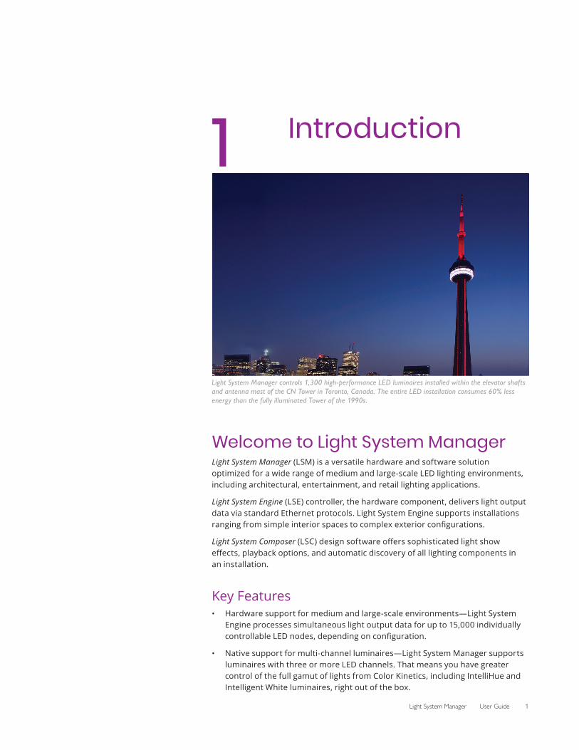
Light System Manager controls 1,300 high-performance LED luminaires installed within the elevator shafts and antenna mast of the CN Tower in Toronto, Canada. The entire LED installation consumes 60% less energy than the fully illuminated Tower of the 1990s.
Welcome to Light System ManagerLight System Manager (LSM) is a versatile hardware and software solution optimized for a wide range of medium and large-scale LED lighting environments, including architectural, entertainment, and retail lighting applications.
Light System Engine (LSE) controller, the hardware component, delivers light output data via standard Ethernet protocols. Light System Engine supports installations ranging from simple interior spaces to complex exterior configurations.
Light System Composer (LSC) design software offers sophisticated light show effects, playback options, and automatic discovery of all lighting components in an installation.
Key Features• Hardware support for medium and large-scale environments—Light System
Engine processes simultaneous light output data for up to 15,000 individually controllable LED nodes, depending on configuration.
• Native support for multi-channel luminaires—Light System Manager supports luminaires with three or more LED channels. That means you have greater control of the full gamut of lights from Color Kinetics, including IntelliHue and Intelligent White luminaires, right out of the box.
2 Chapter 1
• Improved reliability—Solid-state drives reduce the number of moving parts to enhance the reliability of the Light System Engine.
• Slimmer profile—Slimmer form factor offers convenient surface mounting, as well as the ability to install in server racks and rackmount cases.
• Flexible mounting options—Integrated mounting tabs allow installation overhead, on vertical surfaces, or on moving architectural or entertainment features.
• Easy to use—Featuring Ethernet-based control and automatic lighting system discovery, Light System Manager dramatically simplifies installation.
• Create shows with Light System Composer—Light System Composer software allows you to create dynamic light shows with fully customizable effects, multi-layer editing, and unique color palettes. You can design shows with single or multiple color-changing effects, animated images, geometric patterns, and more.
• Web interface access—Set event triggering, create show schedules, and easily select point-and-click static color scenes using an online web interface. The web interface supports multiple online users with activity logging for each user account.
• Dual configurable network ports—The Light System Engine contains two network ports that support integration into existing network environments, while maintaining connectivity to a separate dedicated lighting network.
• ActiveSite integration—ActiveSite is the first ever cloud-hosted connected lighting system for architectural LED lighting installations. ActiveSite allows you to remotely monitor, manage, and maintain an installation site from anywhere in the world, using a secure web connection.
• Versatile zone usage—Configure and control multiple playback zones, each with unique light show assignments. Light System Manager allows zone control of both indoor and outdoor fixtures within a single installation.
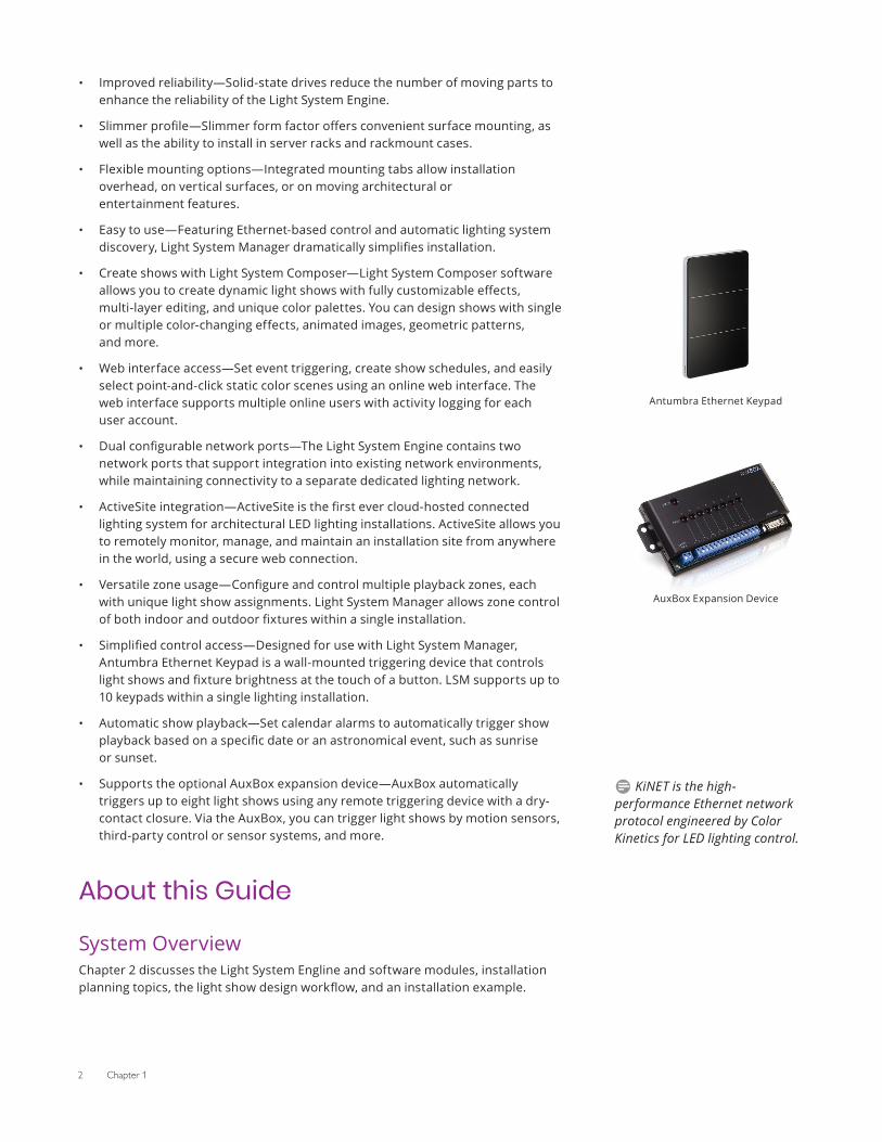
• Simplified control access—Designed for use with Light System Manager, Antumbra Ethernet Keypad is a wall-mounted triggering device that controls light shows and fixture brightness at the touch of a button. LSM supports up to 10 keypads within a single lighting installation.
• Automatic show playback—Set calendar alarms to automatically trigger show playback based on a specific date or an astronomical event, such as sunrise or sunset.
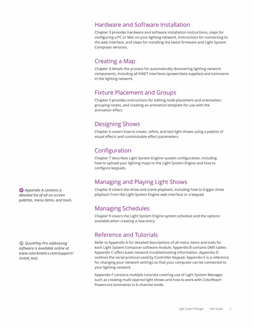
• Supports the optional AuxBox expansion device—AuxBox automatically triggers up to eight light shows using any remote triggering device with a dry-contact closure. Via the AuxBox, you can trigger light shows by motion sensors, third-party control or sensor systems, and more.
About this Guide
System OverviewChapter 2 discusses the Light System Engline and software modules, installation planning topics, the light show design workflow, and an installation example.
AuxBox Expansion Device
Antumbra Ethernet Keypad
D KiNET is the high-performance Ethernet network protocol engineered by Color Kinetics for LED lighting control.
Light System Manager User Guide 3
Hardware and Software InstallationChapter 3 provides hardware and software installation instructions, steps for configuring a PC or Mac on your lighting network, instructions for connecting to the web interface, and steps for installing the latest firmware and Light System Composer versions.
Creating a MapChapter 4 details the process for automatically discovering lighting network components, including all KiNET interfaces (power/data supplies) and luminaires in the lighting network.
Fixture Placement and GroupsChapter 5 provides instructions for editing node placement and orientation, grouping nodes, and creating an animation template for use with the animation effect.
Designing ShowsChapter 6 covers how to create, refine, and test light shows using a palette of visual effects and customizable effect parameters.
ConfigurationChapter 7 describes Light System Engline system configuration, including how to upload your lighting maps to the Light System Engine and how to configure keypads.
Managing and Playing Light ShowsChapter 8 covers the show and scene playback, including how to trigger show playback from the Light System Engine web interface or a keypad.
Managing SchedulesChapter 9 covers the Light System Engine system schedule and the options available when creating a new entry.
Reference and TutorialsRefer to Appendix A for detailed descriptions of all menu items and tools for each Light System Composer software module. Appendix B contains DMX tables. Appendix C offers basic network troubleshooting information. Appendix D outlines the serial protocol used by Controller Keypad. Appendix E is a reference for changing your network settings so that your computer can be connected to your lighting network.
Appendix F contains multiple tutorials covering use of Light System Manager, such as creating multi-layered light shows and how to work with ColorReach Powercore luminaires in 6-channel mode.
E Appendix A contains a detailed list of all on-screen palettes, menu items, and tools.
D QuickPlay Pro addressing software is available online at www.colorkinetics.com/support/install_tool.

4 Chapter 1
Related DocumentsThe following PDF documents are available for download via the web at www.colorkinetics.com/ls/controllers/lsm/
• Light System Manager Installation Instructions
• Light System Manager Quick Start Guide
• Light System Manager Specification Sheet
• Light System Manager Product Guide
Documentation for the optional Antumbra Ethernet Keypad is available online from www.colorkinetics.com/ls/controllers/.
Documentation for the optional serial Controller Keypad is available online from www.colorkinetics.com/ls/controllers/controllerkeypad/.
Documentation for the optional AuxBox is available online from www.colorkinetics.com/ls/controllers/auxbox/.
Technical Support ContactsContact Color Kinetics technical support for assistance with hardware or software questions:
Phone888.385.5742, press option number 3 (toll free US, Canada and Mexico)
+1 617.423.9999, press option number 3 (toll worldwide)
Webwww.colorkinetics.com/support
Light System Manager User Guide 5
2 System Overview
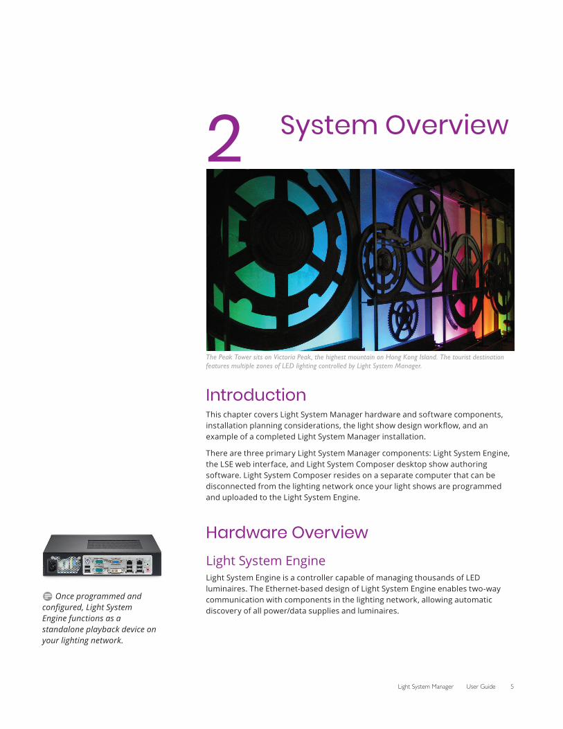
The Peak Tower sits on Victoria Peak, the highest mountain on Hong Kong Island. The tourist destination features multiple zones of LED lighting controlled by Light System Manager.
IntroductionThis chapter covers Light System Manager hardware and software components, installation planning considerations, the light show design workflow, and an example of a completed Light System Manager installation.
There are three primary Light System Manager components: Light System Engine, the LSE web interface, and Light System Composer desktop show authoring software. Light System Composer resides on a separate computer that can be disconnected from the lighting network once your light shows are programmed and uploaded to the Light System Engine.
Hardware OverviewLight System EngineLight System Engine is a controller capable of managing thousands of LED luminaires. The Ethernet-based design of Light System Engine enables two-way communication with components in the lighting network, allowing automatic discovery of all power/data supplies and luminaires.
D Once programmed and configured, Light System Engine functions as a standalone playback device on your lighting network.
6 Chapter 2
Supporting HardwareOne or more Ethernet switches, Cat. 5e or better cabling, and a personal computer (PC or Mac, for initial programming and setup) are required for the Light System Manager installation. Light System Engine stores all light show, configuration, and playback scheduling data on an internal solid-state drive.
Optional HardwareController Keypads (RS-232 serial connection) and Antumbra Ethernet Keypads are optional wall-mounted devices used to manage Light System Manager installations. All keypads feature touchbutton show playback, brightness, and fixture on/off controls.
The AuxBox expansion device is also compatible with Light System Engine, over a serial connection. AuxBox triggers show playback via up to eight contact closure-type switches.
Light System Composer Software ModulesLight System Composer is a light show design software package. There are two modules in Light System Composer, which you use in the following order:
1. Management Tool
2. Show Designer
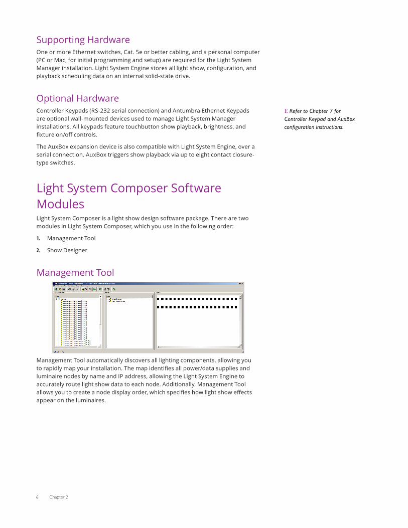
Management Tool
Management Tool automatically discovers all lighting components, allowing you to rapidly map your installation. The map identifies all power/data supplies and luminaire nodes by name and IP address, allowing the Light System Engine to accurately route light show data to each node. Additionally, Management Tool allows you to create a node display order, which specifies how light show effects appear on the luminaires.
E Refer to Chapter 7 for Controller Keypad and AuxBox configuration instructions.
Light System Manager User Guide 7
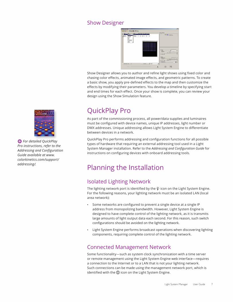
Show Designer
Show Designer allows you to author and refine light shows using fixed color and chasing color effects, animated image effects, and geometric patterns. To create a basic show, you apply pre-defined effects to the map and then customize the effects by modifying their parameters. You develop a timeline by specifying start and end times for each effect. Once your show is complete, you can review your design using the Show Simulation feature.
QuickPlay ProAs part of the commissioning process, all power/data supplies and luminaires must be configured with device names, unique IP addresses, light number or DMX addresses. Unique addressing allows Light System Engine to differentiate between devices in a network.
QuickPlay Pro performs addressing and configuration functions for all possible types of hardware that requiring an external addressing tool used in a Light System Manager installation. Refer to the Addressing and Configuration Guide for instructions on configuring devices with onboard addressing tools.
Planning the Installation
Isolated Lighting NetworkThe lighting network port is identified by the icon on the Light System Engine. For the following reasons, your lighting network must be an isolated LAN (local area network):
• Some networks are configured to prevent a single device at a single IP address from monopolizing bandwidth. However, Light System Engine is designed to have complete control of the lighting network, as it is transmits large amounts of light output data each second. For this reason, such switch configurations should be avoided on the lighting network.
• Light System Engine performs broadcast operations when discovering lighting components, requiring complete control of the lighting network.
Connected Management NetworkSome functionality—such as system clock synchronization with a time server or remote management using the Light System Engine web interface—requires a connection to the Internet or to a LAN that is not your lighting network. Such connections can be made using the management network port, which is identified with the icon on the Light System Engine.
E For detailed QuickPlay Pro instructions, refer to the Addressing and Configuration Guide available at www.colorkinetics.com/support/addressing/.
8 Chapter 2
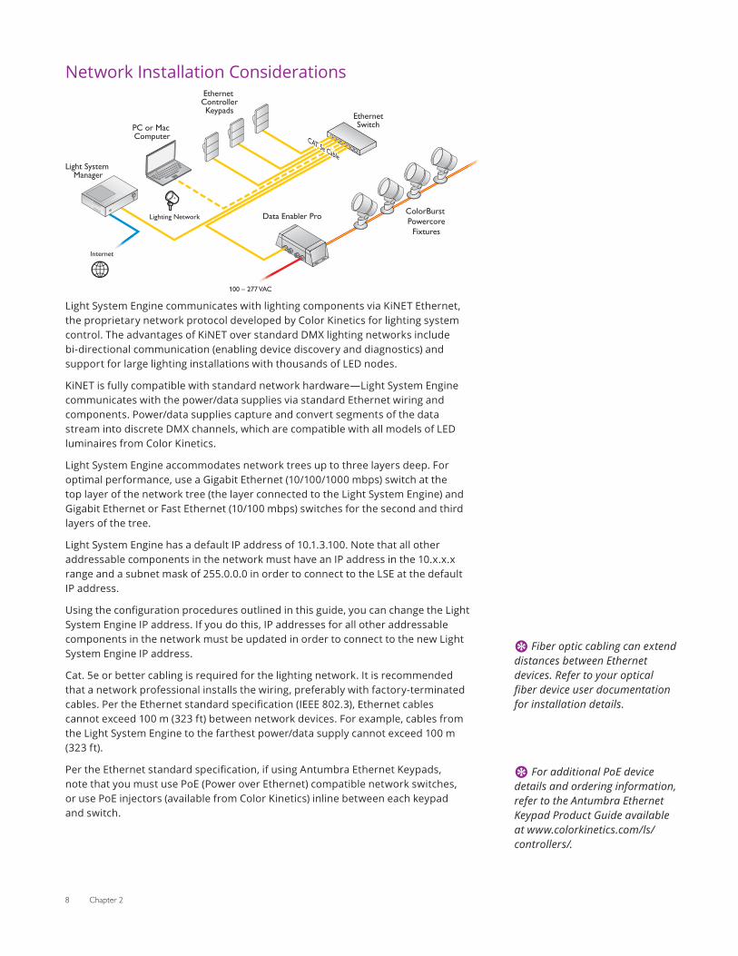
Network Installation Considerations
Light System Manager
Ethernet ControllerKeypads Ethernet
Switch
ColorBurst Powercore
Fixtures
Data Enabler Pro
100 – 277 VAC
CAT 5e Cable
CAT 5e Cable
PC or Mac Computer
Internet
Lighting Network
Light System Engine communicates with lighting components via KiNET Ethernet, the proprietary network protocol developed by Color Kinetics for lighting system control. The advantages of KiNET over standard DMX lighting networks include bi-directional communication (enabling device discovery and diagnostics) and support for large lighting installations with thousands of LED nodes.
KiNET is fully compatible with standard network hardware—Light System Engine communicates with the power/data supplies via standard Ethernet wiring and components. Power/data supplies capture and convert segments of the data stream into discrete DMX channels, which are compatible with all models of LED luminaires from Color Kinetics.
Light System Engine accommodates network trees up to three layers deep. For optimal performance, use a Gigabit Ethernet (10/100/1000 mbps) switch at the top layer of the network tree (the layer connected to the Light System Engine) and Gigabit Ethernet or Fast Ethernet (10/100 mbps) switches for the second and third layers of the tree.
Light System Engine has a default IP address of 10.1.3.100. Note that all other addressable components in the network must have an IP address in the 10.x.x.x range and a subnet mask of 255.0.0.0 in order to connect to the LSE at the default IP address.
Using the configuration procedures outlined in this guide, you can change the Light System Engine IP address. If you do this, IP addresses for all other addressable components in the network must be updated in order to connect to the new Light System Engine IP address.
Cat. 5e or better cabling is required for the lighting network. It is recommended that a network professional installs the wiring, preferably with factory-terminated cables. Per the Ethernet standard specification (IEEE 802.3), Ethernet cables cannot exceed 100 m (323 ft) between network devices. For example, cables from the Light System Engine to the farthest power/data supply cannot exceed 100 m (323 ft).
Per the Ethernet standard specification, if using Antumbra Ethernet Keypads, note that you must use PoE (Power over Ethernet) compatible network switches, or use PoE injectors (available from Color Kinetics) inline between each keypad and switch.
E Fiber optic cabling can extend distances between Ethernet devices. Refer to your optical fiber device user documentation for installation details.
E For additional PoE device details and ordering information, refer to the Antumbra Ethernet Keypad Product Guide available at www.colorkinetics.com/ls/controllers/.
Light System Manager User Guide 9
Lighting System Installation ConsiderationsColor Kinetics offers lighting systems suitable for environments ranging from the simplest to the most complex. A simple installation might use 25 ColorGraze® MX4 Powercore luminaires installed in a single zone, whereas a larger installation might use 150 strands of iColor® Flex LMX gen2 and 50 iColor Accent Compact luminaires displaying light shows in multiple zones. Regardless of the complexity of your installation, keep these suggestions in mind:
• Create a lighting design (CAD layout, architectural plan, or other diagram) that specifies the locations of all luminaires, power/data supplies, Ethernet switches, Ethernet cables, the Light System Engine, and keypads.
• Use the Configuration Calculator from Color Kinetics, and the appropriate Product Guides and wiring diagrams, to determine the number of luminaires each circuit in your installation can support.
• As part of the lighting design plan, where possible, make use of a repeated layout that specifies the preferred orientation of each luminaire.
• To streamline physical installation and future maintenance, affix a weatherproof label identifying installation placement, IP address, and device name to an inconspicuous location on each power/data supply and luminaire.
• If installing in hard-to-reach areas, test, address, and configure the luminaires before physically installing them.
Addressing and ConfigurationPrior to mapping your lighting components with Light System Composer, use QuickPlay Pro or built-in device addressing tools to assign unique IP addresses and device names to the power/data supplies and luminaires in your lighting network. When addressing and naming components, use a logical IP addressing scheme or convention that identifies where each device is located.
Addressing Methods• Serial addressing applies to most Chromacore luminaires (Chromacore
luminaires receive light numbers based on serial numbers).
• Base light number configuration applies to all Chromasic and Accent family luminaires.
• Onboard addressing applies to power/data supplies that have onboard hardware addressing controls. QuickPlay Pro is not used to address power/data supplies that have onboard addressing features.
Workflow: Creating and Displaying Shows
1. Create a MapMapping the installation is the first step in creating a light show. The map links all luminaires and power/data supplies to the Light System Engine, and acts as a virtual representation of the installation. The Management Tool module in Light System Composer enables you to automatically discover all lighting system components on the map. When new luminaires are added to an existing installation, or when working off site, the Management Tool module also allows
D The Configuration Calculator is available online at www.colorkinetics.com/support/install_tool/.
10 Chapter 2
you to manually add power/data supplies and luminaires to the map. Once all lighting components are mapped, you can organize them into groups. Groups create a sequential order by which luminaires display light output.
2. Create a Light ShowWhen a map is completed, the next step is to create a light show with one or more effects. The Show Designer module lets you add effects to each group of luminaires in the installation and then modify the effect parameters to create unique results. Effects can be stacked for added depth and sophistication. Once effects are assigned, you can use the simulation feature to test and refine your show.
3. Create Playback Schedules, Zones, and TriggersThe next steps are to upload your map and light shows to the Light System Engine and to configure playback schedules, playback zones, and remote device triggering in the LSE web interface.
After uploading the files created in steps 1 and 2 and creating a playback schedule, the Light System Engine automatically plays designated light shows according to a schedule or when triggered by an external triggering device (a keypad or AuxBox, for example). No external computer is necessary for playback—Light System Engine functions as a standalone controller (you can remove your PC or Mac from the isolated lighting network).
Optionally, you can use the LSE web interface to override automatic scheduling and triggers.
Installation ExampleThe Color Kinetics headquarters comprises 4,645 m2 (50,000 ft2) of office, laboratory, and showroom space that utilizes LED lighting technology throughout. Light System Manager is the control solution managing multiple lighting zones in the building, including the lobby, conference rooms, work spaces, exterior signage, and product demonstration areas.
Light System Manager User Guide 11
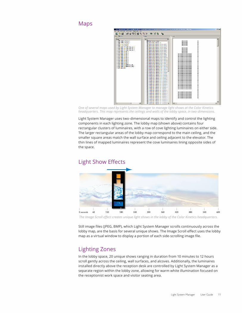
Maps
One of several maps used by Light System Manager to manage light shows at the Color Kinetics headquarters. This map represents the ceilings and walls of the lobby space, in two-dimensions.
Light System Manager uses two-dimensional maps to identify and control the lighting components in each lighting zone. The lobby map (shown above) contains four rectangular clusters of luminaires, with a row of cove lighting luminaires on either side. The larger rectangular areas of the lobby map correspond to the main ceiling, and the smaller square areas match the wall surface and ceiling adjacent to the elevator. The thin lines of mapped luminaires represent the cove luminaires lining opposite sides of the space.
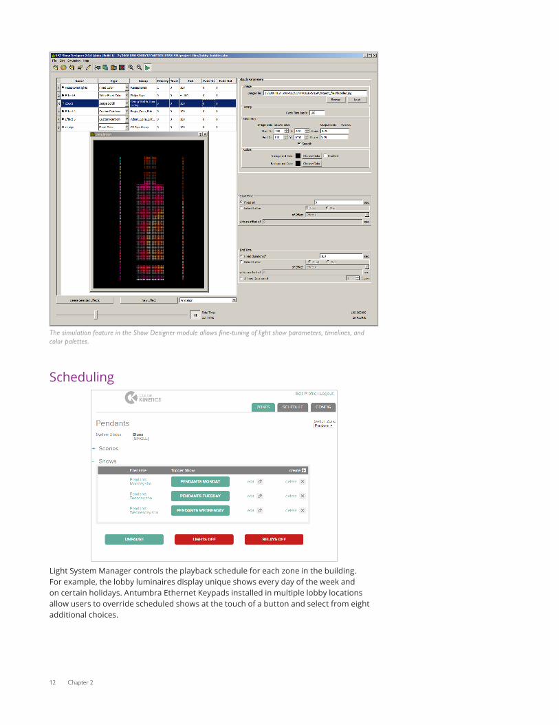
Light Show Effects
0 seconds 60 120 180 240 300 360 420 480 540 600
The Image Scroll effect creates unique light shows in the lobby of the Color Kinetics headquarters.
Still image files ( JPEG, BMP), which Light System Manager scrolls continuously across the lobby map, are the basis for several unique shows. The Image Scroll effect uses the lobby map as a virtual window to display a portion of each side-scrolling image file.
Lighting ZonesIn the lobby space, 20 unique shows ranging in duration from 10 minutes to 12 hours scroll gently across the ceiling, wall surfaces, and alcoves. Additionally, the luminaires installed directly above the reception desk are controlled by Light System Manager as a separate region within the lobby zone, allowing for warm white illumination focused on the receptionist work space and visitor seating area.
12 Chapter 2
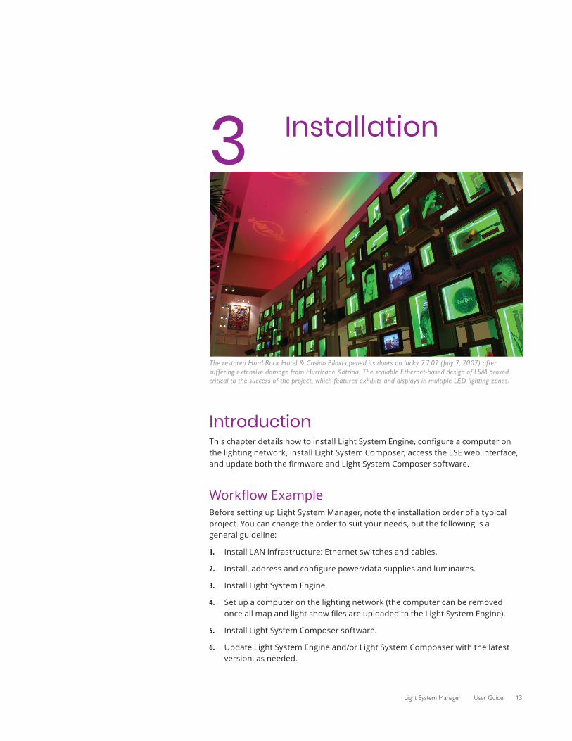
The simulation feature in the Show Designer module allows fine-tuning of light show parameters, timelines, and color palettes.
Scheduling
Light System Manager controls the playback schedule for each zone in the building. For example, the lobby luminaires display unique shows every day of the week and on certain holidays. Antumbra Ethernet Keypads installed in multiple lobby locations allow users to override scheduled shows at the touch of a button and select from eight additional choices.
Light System Manager User Guide 13
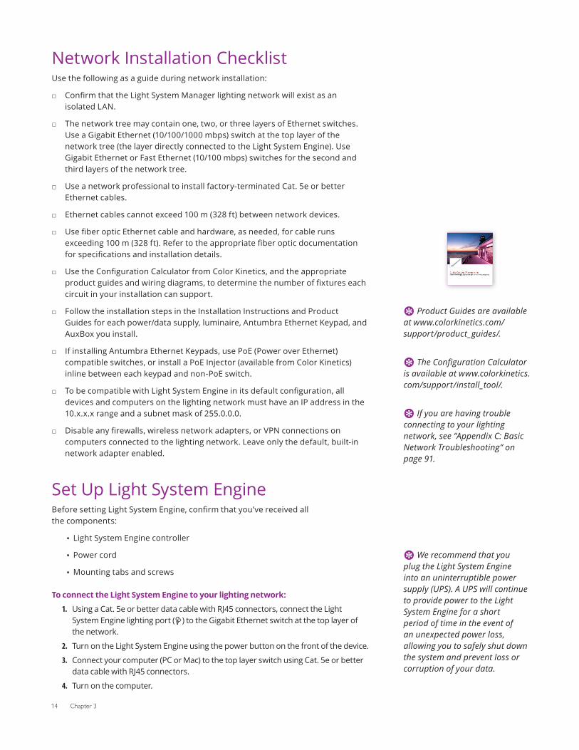
3 Installation
The restored Hard Rock Hotel & Casino Biloxi opened its doors on lucky 7.7.07 (July 7, 2007) after suffering extensive damage from Hurricane Katrina. The scalable Ethernet-based design of LSM proved critical to the success of the project, which features exhibits and displays in multiple LED lighting zones.
IntroductionThis chapter details how to install Light System Engine, configure a computer on the lighting network, install Light System Composer, access the LSE web interface, and update both the firmware and Light System Composer software.
Workflow ExampleBefore setting up Light System Manager, note the installation order of a typical project. You can change the order to suit your needs, but the following is a general guideline:
1. Install LAN infrastructure: Ethernet switches and cables.
2. Install, address and configure power/data supplies and luminaires.
3. Install Light System Engine.
4. Set up a computer on the lighting network (the computer can be removed once all map and light show files are uploaded to the Light System Engine).
5. Install Light System Composer software.
6. Update Light System Engine and/or Light System Compoaser with the latest version, as needed.
14 Chapter 3
Network Installation ChecklistUse the following as a guide during network installation:
□ Confirm that the Light System Manager lighting network will exist as an isolated LAN.
□ The network tree may contain one, two, or three layers of Ethernet switches. Use a Gigabit Ethernet (10/100/1000 mbps) switch at the top layer of the network tree (the layer directly connected to the Light System Engine). Use Gigabit Ethernet or Fast Ethernet (10/100 mbps) switches for the second and third layers of the network tree.
□ Use a network professional to install factory-terminated Cat. 5e or better Ethernet cables.
□ Ethernet cables cannot exceed 100 m (328 ft) between network devices.
□ Use fiber optic Ethernet cable and hardware, as needed, for cable runs exceeding 100 m (328 ft). Refer to the appropriate fiber optic documentation for specifications and installation details.
□ Use the Configuration Calculator from Color Kinetics, and the appropriate product guides and wiring diagrams, to determine the number of fixtures each circuit in your installation can support.
□ Follow the installation steps in the Installation Instructions and Product Guides for each power/data supply, luminaire, Antumbra Ethernet Keypad, and AuxBox you install.
□ If installing Antumbra Ethernet Keypads, use PoE (Power over Ethernet) compatible switches, or install a PoE Injector (available from Color Kinetics) inline between each keypad and non-PoE switch.
□ To be compatible with Light System Engine in its default configuration, all devices and computers on the lighting network must have an IP address in the 10.x.x.x range and a subnet mask of 255.0.0.0.
□ Disable any firewalls, wireless network adapters, or VPN connections on computers connected to the lighting network. Leave only the default, built-in network adapter enabled.
Set Up Light System EngineBefore setting Light System Engine, confirm that you’ve received all the components:
▪ Light System Engine controller
▪ Power cord
▪ Mounting tabs and screws
To connect the Light System Engine to your lighting network:
1. Using a Cat. 5e or better data cable with RJ45 connectors, connect the Light System Engine lighting port ( ) to the Gigabit Ethernet switch at the top layer of the network.
2. Turn on the Light System Engine using the power button on the front of the device.
3. Connect your computer (PC or Mac) to the top layer switch using Cat. 5e or better data cable with RJ45 connectors.
4. Turn on the computer.
E Product Guides are available at www.colorkinetics.com/support/product_guides/.
E The Configuration Calculator is available at www.colorkinetics.com/support/install_tool/.
E If you are having trouble connecting to your lighting network, see “Appendix C: Basic Network Troubleshooting” on page 91.
E We recommend that you plug the Light System Engine into an uninterruptible power supply (UPS). A UPS will continue to provide power to the Light System Engine for a short period of time in the event of an unexpected power loss, allowing you to safely shut down the system and prevent loss or corruption of your data.
Light System Manager User Guide 15
Configuring a PC or Mac on the NetworkA computer connected to the lighting network allows you to perform light show programming and configuration tasks using Light System Composer software. The computer can be disconnected once all setup functions are complete, or the computer can reside permanently on the network.
Light System Engine is assigned the IP address of 10.1.3.100 by factory default. In order access the LSE web interface from your web browser, you must configure your computer with a static IP address in the 10.x.x.x range and the Subnet Mask of 255.0.0.0. Refer to “Appendix E: IP Address Configuration” on page 97 for instructions on how to configure a static IP address on your PC or Mac.
To verify that IP address configuration on the computer has succeeded, connect to the LSE web interface from your computer.
Connect to the LSE Web InterfaceWith your Light System Engine (LSE) and computer connected to the lighting network and powered on, test your network connection by accessing the LSE web interface:
To connect to the LSE web interface:
1. Configure your computer with a static IP address in the 10.x.x.x range and the subnet mask of 255.0.0.0.
2. Open a web browser, and type 10.1.3.100 (the default IP address) in the Address bar. Light System Engine uses a self-signed SSL certificate, so you should bypass any SSL certificate warnings.
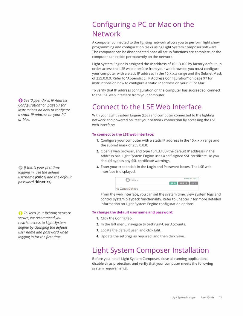
3. Enter your credentials in the Login and Password boxes. The LSE web interface is displayed.
From the web interface, you can set the system time, view system logs and control system playback functionality. Refer to Chapter 7 for more detailed information on Light System Engine configuration options.
To change the default username and password:
1. Click the Config tab.
2. In the left menu, navigate to Settings>User Accounts.
3. Locate the default user, and click Edit.
4. Update the settings as required, and then click Save.
Light System Composer InstallationBefore you install Light System Composer, close all running applications, disable virus protection, and verify that your computer meets the following system requirements.
E See “Appendix E: IP Address Configuration” on page 97 for instructions on how to configure a static IP address on your PC or Mac.
D If this is your first time logging in, use the default username (color) and the default password (kinetics).
C To keep your lighting network secure, we recommend you restrict access to Light System Engine by changing the default user name and password when logging in for the first time.
16 Chapter 3
System RequirementsLight System Composer requires 64-bit Windows 7 or newer, or macOS 10.10 or newer, and at least 100 MB free storage space.
Install Light System Composer
To install Light System Composer on Windows:
1. Download Light System Composer from www.colorkinetics.com/support/lsm/ to your computer.
2. Unzip the file you downloaded, and open the Light System Composer folder.
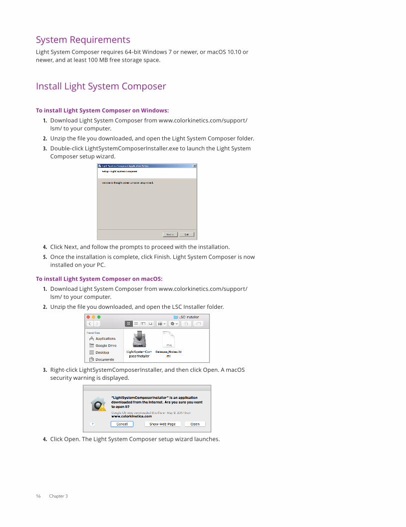
3. Double-click LightSystemComposerInstaller.exe to launch the Light System Composer setup wizard.
4. Click Next, and follow the prompts to proceed with the installation.
5. Once the installation is complete, click Finish. Light System Composer is now installed on your PC.
To install Light System Composer on macOS:
1. Download Light System Composer from www.colorkinetics.com/support/lsm/ to your computer.
2. Unzip the file you downloaded, and open the LSC Installer folder.
3. Right-click LightSystemComposerInstaller, and then click Open. A macOS security warning is displayed.
4. Click Open. The Light System Composer setup wizard launches.
Light System Manager User Guide 17
5. Click Next, and follow the prompts to proceed with the installation.
6. Once the installation is complete, click Finish. Light System Composer is now installed on your Mac.
Update Light System ComposerOccasionally, Light System Composer is updated to provide feature improvements and enhancements. The latest version of Light System Composer is always available at www.colorkinetics.com/support/lsm/.
To find the Light System Composer software version:
1. Open Show Designer.
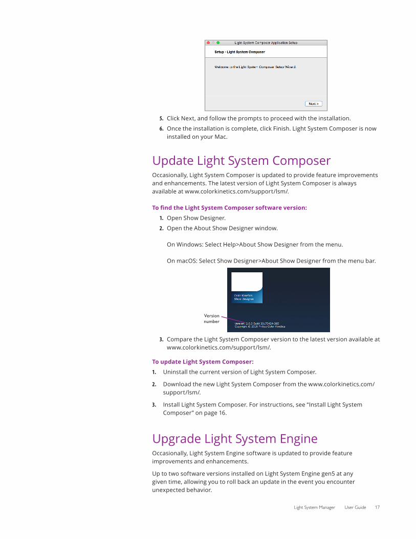
2. Open the About Show Designer window. On Windows: Select Help>About Show Designer from the menu. On macOS: Select Show Designer>About Show Designer from the menu bar.
3.
Version number
Compare the Light System Composer version to the latest version available at www.colorkinetics.com/support/lsm/.
To update Light System Composer:
1. Uninstall the current version of Light System Composer.
2. Download the new Light System Composer from the www.colorkinetics.com/support/lsm/.
3. Install Light System Composer. For instructions, see “Install Light System Composer” on page 16.
Upgrade Light System EngineOccasionally, Light System Engine software is updated to provide feature improvements and enhancements.
Up to two software versions installed on Light System Engine gen5 at any given time, allowing you to roll back an update in the event you encounter unexpected behavior.
18 Chapter 3
Software updates are available at www.colorkinetics.com/support/lsm/. You can update your software through the LSE web interface.
To find your Light System Engine software version:
1. Click the Config tab.
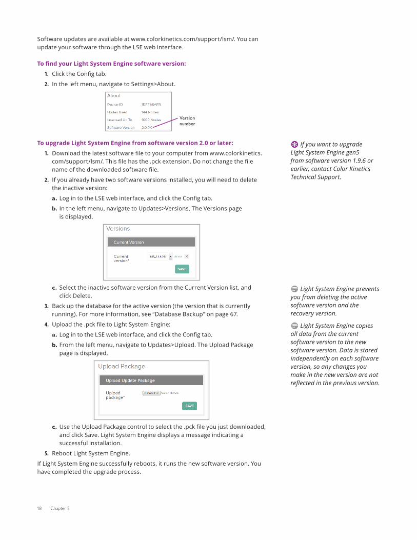
2. In the left menu, navigate to Settings>About.
Version number
To upgrade Light System Engine from software version 2.0 or later:
1. Download the latest software file to your computer from www.colorkinetics.com/support/lsm/. This file has the .pck extension. Do not change the file name of the downloaded software file.
2. If you already have two software versions installed, you will need to delete the inactive version:
a. Log in to the LSE web interface, and click the Config tab.
b. In the left menu, navigate to Updates>Versions. The Versions page is displayed.
c. Select the inactive software version from the Current Version list, and click Delete.
3. Back up the database for the active version (the version that is currently running). For more information, see “Database Backup” on page 67.
4. Upload the .pck file to Light System Engine:
a. Log in to the LSE web interface, and click the Config tab.
b. From the left menu, navigate to Updates>Upload. The Upload Package page is displayed.
c. Use the Upload Package control to select the .pck file you just downloaded, and click Save. Light System Engine displays a message indicating a successful installation.
5. Reboot Light System Engine.
If Light System Engine successfully reboots, it runs the new software version. You have completed the upgrade process.
E If you want to upgrade Light System Engine gen5 from software version 1.9.6 or earlier, contact Color Kinetics Technical Support.
D Light System Engine prevents you from deleting the active software version and the recovery version.
D Light System Engine copies all data from the current software version to the new software version. Data is stored independently on each software version, so any changes you make in the new version are not reflected in the previous version.
Light System Manager User Guide 19
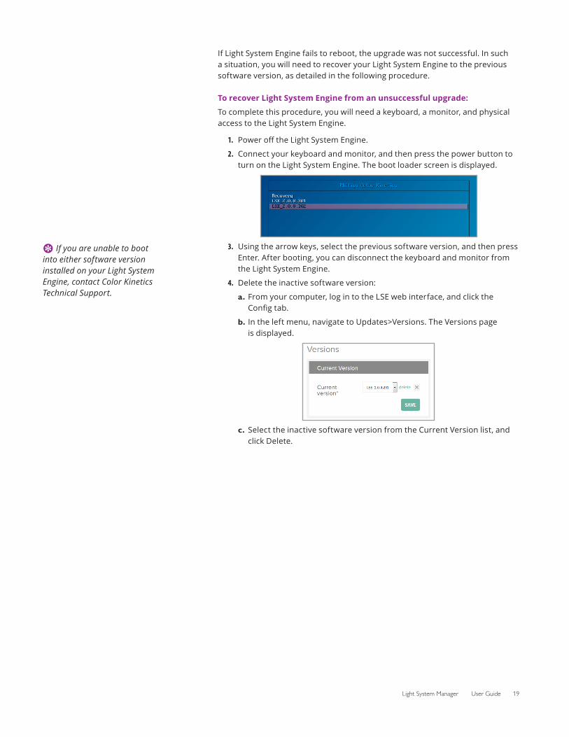
If Light System Engine fails to reboot, the upgrade was not successful. In such a situation, you will need to recover your Light System Engine to the previous software version, as detailed in the following procedure.
To recover Light System Engine from an unsuccessful upgrade:
To complete this procedure, you will need a keyboard, a monitor, and physical access to the Light System Engine.
1. Power off the Light System Engine.
2. Connect your keyboard and monitor, and then press the power button to turn on the Light System Engine. The boot loader screen is displayed.
3. Using the arrow keys, select the previous software version, and then press Enter. After booting, you can disconnect the keyboard and monitor from the Light System Engine.
4. Delete the inactive software version:
a. From your computer, log in to the LSE web interface, and click the Config tab.
b. In the left menu, navigate to Updates>Versions. The Versions page is displayed.
c. Select the inactive software version from the Current Version list, and click Delete.
E If you are unable to boot into either software version installed on your Light System Engine, contact Color Kinetics Technical Support.
Light System Manager User Guide 20
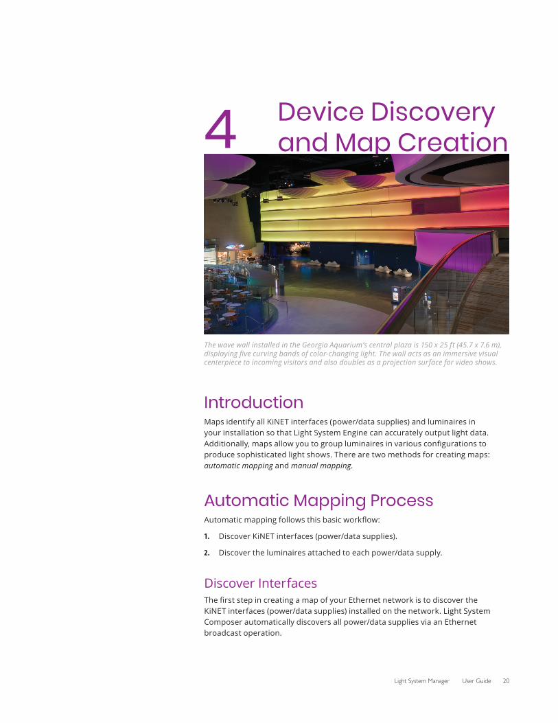
4 Device Discovery and Map Creation
The wave wall installed in the Georgia Aquarium’s central plaza is 150 x 25 ft (45.7 x 7.6 m), displaying five curving bands of color-changing light. The wall acts as an immersive visual centerpiece to incoming visitors and also doubles as a projection surface for video shows.
IntroductionMaps identify all KiNET interfaces (power/data supplies) and luminaires in your installation so that Light System Engine can accurately output light data. Additionally, maps allow you to group luminaires in various configurations to produce sophisticated light shows. There are two methods for creating maps: automatic mapping and manual mapping.
Automatic Mapping ProcessAutomatic mapping follows this basic workflow:
1. Discover KiNET interfaces (power/data supplies).
2. Discover the luminaires attached to each power/data supply.
Discover InterfacesThe first step in creating a map of your Ethernet network is to discover the KiNET interfaces (power/data supplies) installed on the network. Light System Composer automatically discovers all power/data supplies via an Ethernet broadcast operation.
21 Chapter 4
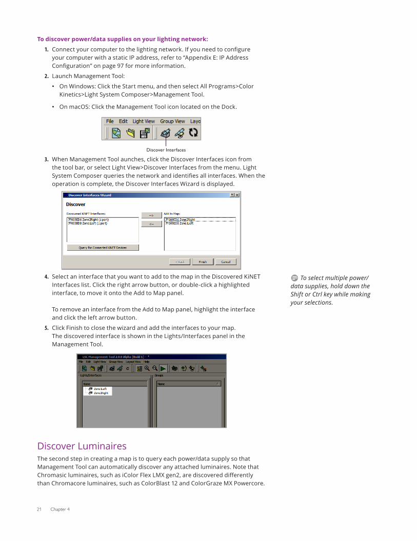
To discover power/data supplies on your lighting network:
1. Connect your computer to the lighting network. If you need to configure your computer with a static IP address, refer to “Appendix E: IP Address Configuration” on page 97 for more information.
2. Launch Management Tool:
• On Windows: Click the Start menu, and then select All Programs>Color Kinetics>Light System Composer>Management Tool.
• On macOS: Click the Management Tool icon located on the Dock.
3.
Discover Interfaces
When Management Tool aunches, click the Discover Interfaces icon from the tool bar, or select Light View>Discover Interfaces from the menu. Light System Composer queries the network and identifies all interfaces. When the operation is complete, the Discover Interfaces Wizard is displayed.
4. Select an interface that you want to add to the map in the Discovered KiNET Interfaces list. Click the right arrow button, or double-click a highlighted interface, to move it onto the Add to Map panel. To remove an interface from the Add to Map panel, highlight the interface and click the left arrow button.
5. Click Finish to close the wizard and add the interfaces to your map. The discovered interface is shown in the Lights/Interfaces panel in the Management Tool.
Discover LuminairesThe second step in creating a map is to query each power/data supply so that Management Tool can automatically discover any attached luminaires. Note that Chromasic luminaires, such as iColor Flex LMX gen2, are discovered differently than Chromacore luminaires, such as ColorBlast 12 and ColorGraze MX Powercore.
D To select multiple power/data supplies, hold down the Shift or Ctrl key while making your selections.
Light System Manager User Guide 22
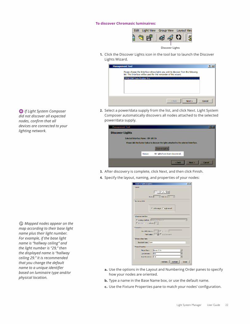
To discover Chromasic luminaires:
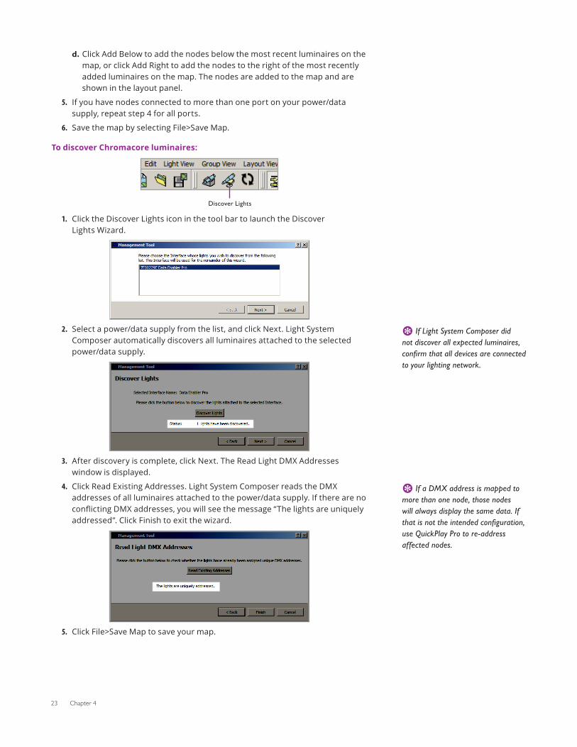
1.
Discover Lights
Click the Discover Lights icon in the tool bar to launch the Discover Lights Wizard.
2. Select a power/data supply from the list, and click Next. Light System Composer automatically discovers all nodes attached to the selected power/data supply.
3. After discovery is complete, click Next, and then click Finish.
4. Specify the layout, naming, and properties of your nodes:
a. Use the options in the Layout and Numbering Order panes to specify how your nodes are oriented.
b. Type a name in the Base Name box, or use the default name.
c. Use the Fixture Properties pane to match your nodes’ configuration.
E If Light System Composer did not discover all expected nodes, confirm that all devices are connected to your lighting network.
D Mapped nodes appear on the map according to their base light name plus their light number. For example, if the base light name is “hallway ceiling” and the light number is “29,” then the displayed name is “hallway ceiling 29.” It is recommended that you change the default name to a unique identifier based on luminaire type and/or physical location.
23 Chapter 4
d. Click Add Below to add the nodes below the most recent luminaires on the map, or click Add Right to add the nodes to the right of the most recently added luminaires on the map. The nodes are added to the map and are shown in the layout panel.
5. If you have nodes connected to more than one port on your power/data supply, repeat step 4 for all ports.
6. Save the map by selecting File>Save Map.
To discover Chromacore luminaires:
1.
Discover Lights
Click the Discover Lights icon in the tool bar to launch the Discover Lights Wizard.
2. Select a power/data supply from the list, and click Next. Light System Composer automatically discovers all luminaires attached to the selected power/data supply.
3. After discovery is complete, click Next. The Read Light DMX Addresses window is displayed.
4. Click Read Existing Addresses. Light System Composer reads the DMX addresses of all luminaires attached to the power/data supply. If there are no conflicting DMX addresses, you will see the message “The lights are uniquely addressed”. Click Finish to exit the wizard.
5. Click File>Save Map to save your map.
E If Light System Composer did not discover all expected luminaires, confirm that all devices are connected to your lighting network.
E If a DMX address is mapped to more than one node, those nodes will always display the same data. If that is not the intended configuration, use QuickPlay Pro to re-address affected nodes.
Light System Manager User Guide 24
Manual Map CreationThe Add tools, located on the tool bar, offer offline mapping functionality. With the Add tools, you can add power/data supplies and luminaires to an existing map when an installation expands, eliminating the need to create a new map from scratch. You can also create placeholder maps that can be associated with installations at a later time, allowing you to create maps and light shows prior to the completion of an actual lighting project.
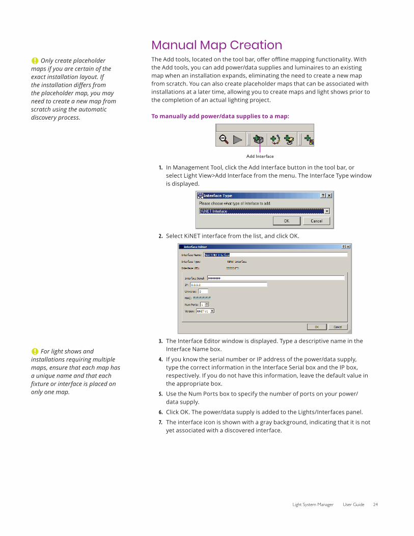
To manually add power/data supplies to a map:
1.
Add Interface
In Management Tool, click the Add Interface button in the tool bar, or select Light View>Add Interface from the menu. The Interface Type window is displayed.
2. Select KiNET interface from the list, and click OK.
3. The Interface Editor window is displayed. Type a descriptive name in the Interface Name box.
4. If you know the serial number or IP address of the power/data supply, type the correct information in the Interface Serial box and the IP box, respectively. If you do not have this information, leave the default value in the appropriate box.
5. Use the Num Ports box to specify the number of ports on your power/data supply.
6. Click OK. The power/data supply is added to the Lights/Interfaces panel.
7. The interface icon is shown with a gray background, indicating that it is not yet associated with a discovered interface.
C Only create placeholder maps if you are certain of the exact installation layout. If the installation differs from the placeholder map, you may need to create a new map from scratch using the automatic discovery process.
C For light shows and installations requiring multiple maps, ensure that each map has a unique name and that each fixture or interface is placed on only one map.
25 Chapter 4
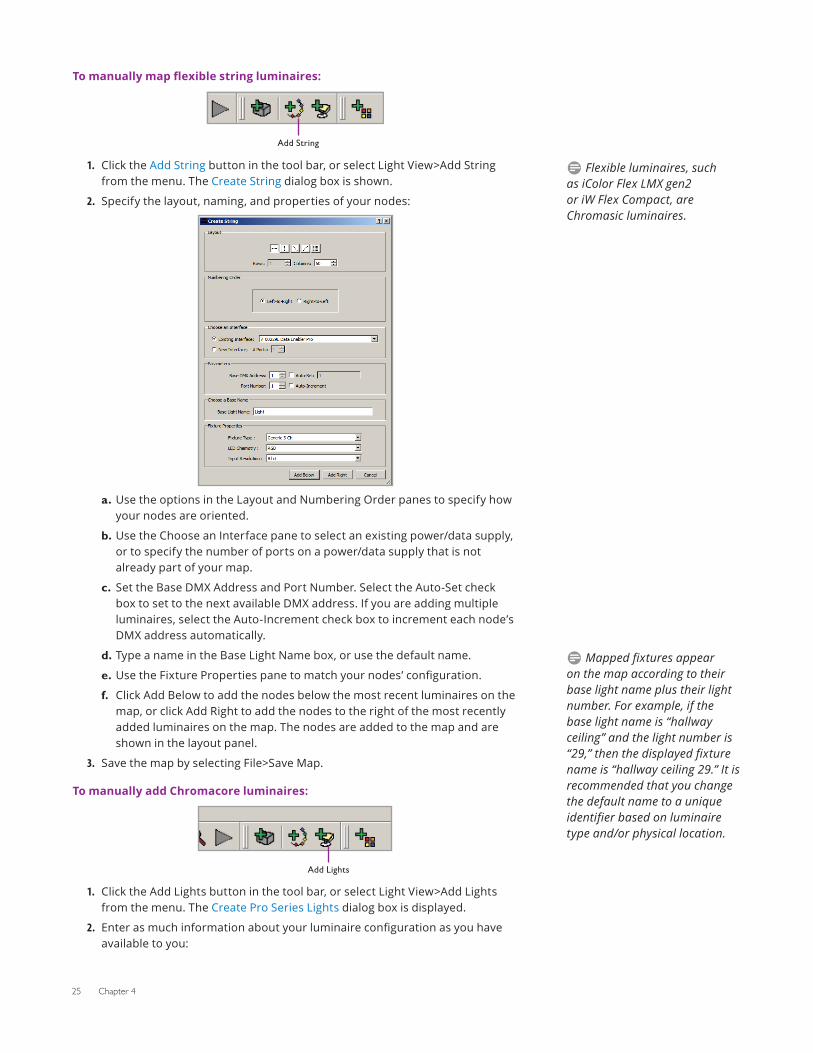
To manually map flexible string luminaires:
1.
Add String
Click the Add String button in the tool bar, or select Light View>Add String from the menu. The Create String dialog box is shown.
2. Specify the layout, naming, and properties of your nodes:
a. Use the options in the Layout and Numbering Order panes to specify how your nodes are oriented.
b. Use the Choose an Interface pane to select an existing power/data supply, or to specify the number of ports on a power/data supply that is not already part of your map.
c. Set the Base DMX Address and Port Number. Select the Auto-Set check box to set to the next available DMX address. If you are adding multiple luminaires, select the Auto-Increment check box to increment each node’s DMX address automatically.
d. Type a name in the Base Light Name box, or use the default name.
e. Use the Fixture Properties pane to match your nodes’ configuration.
f. Click Add Below to add the nodes below the most recent luminaires on the map, or click Add Right to add the nodes to the right of the most recently added luminaires on the map. The nodes are added to the map and are shown in the layout panel.
3. Save the map by selecting File>Save Map.
To manually add Chromacore luminaires:
1.
Add Lights
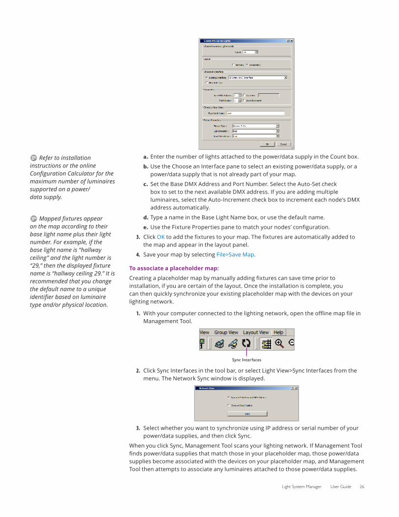
Click the Add Lights button in the tool bar, or select Light View>Add Lights from the menu. The Create Pro Series Lights dialog box is displayed.
2. Enter as much information about your luminaire configuration as you have available to you:
D Flexible luminaires, such as iColor Flex LMX gen2 or iW Flex Compact, are Chromasic luminaires.
D Mapped fixtures appear on the map according to their base light name plus their light number. For example, if the base light name is “hallway ceiling” and the light number is “29,” then the displayed fixture name is “hallway ceiling 29.” It is recommended that you change the default name to a unique identifier based on luminaire type and/or physical location.
Light System Manager User Guide 26
a. Enter the number of lights attached to the power/data supply in the Count box.
b. Use the Choose an Interface pane to select an existing power/data supply, or a power/data supply that is not already part of your map.
c. Set the Base DMX Address and Port Number. Select the Auto-Set check box to set to the next available DMX address. If you are adding multiple luminaires, select the Auto-Increment check box to increment each node’s DMX address automatically.
d. Type a name in the Base Light Name box, or use the default name.
e. Use the Fixture Properties pane to match your nodes’ configuration.
3. Click OK to add the fixtures to your map. The fixtures are automatically added to the map and appear in the layout panel.
4. Save your map by selecting File>Save Map.
To associate a placeholder map:
Creating a placeholder map by manually adding fixtures can save time prior to installation, if you are certain of the layout. Once the installation is complete, you can then quickly synchronize your existing placeholder map with the devices on your lighting network.
1. With your computer connected to the lighting network, open the offline map file in Management Tool.
2.
Sync Interfaces
Click Sync Interfaces in the tool bar, or select Light View>Sync Interfaces from the menu. The Network Sync window is displayed.
3. Select whether you want to synchronize using IP address or serial number of your power/data supplies, and then click Sync.
When you click Sync, Management Tool scans your lighting network. If Management Tool finds power/data supplies that match those in your placeholder map, those power/data supplies become associated with the devices on your placeholder map, and Management Tool then attempts to associate any luminaires attached to those power/data supplies.
D Refer to installation instructions or the online Configuration Calculator for the maximum number of luminaires supported on a power/data supply.
D Mapped fixtures appear on the map according to their base light name plus their light number. For example, if the base light name is “hallway ceiling” and the light number is “29,” then the displayed fixture name is “hallway ceiling 29.” It is recommended that you change the default name to a unique identifier based on luminaire type and/or physical location.
27 Chapter 4
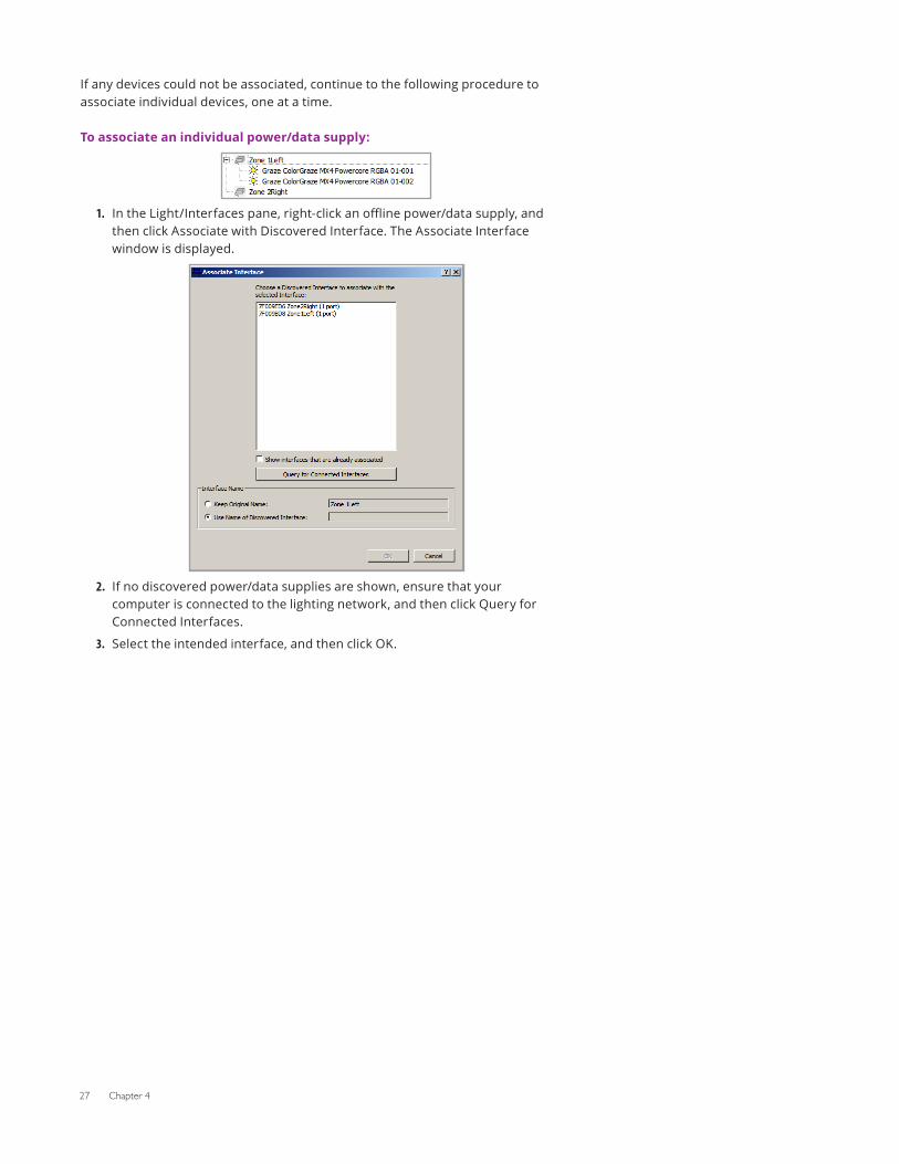
If any devices could not be associated, continue to the following procedure to associate individual devices, one at a time.
To associate an individual power/data supply:
1. In the Light/Interfaces pane, right-click an offline power/data supply, and then click Associate with Discovered Interface. The Associate Interface window is displayed.
2. If no discovered power/data supplies are shown, ensure that your computer is connected to the lighting network, and then click Query for Connected Interfaces.
3. Select the intended interface, and then click OK.
Light System Manager User Guide 28
5 Map Layout and Groups
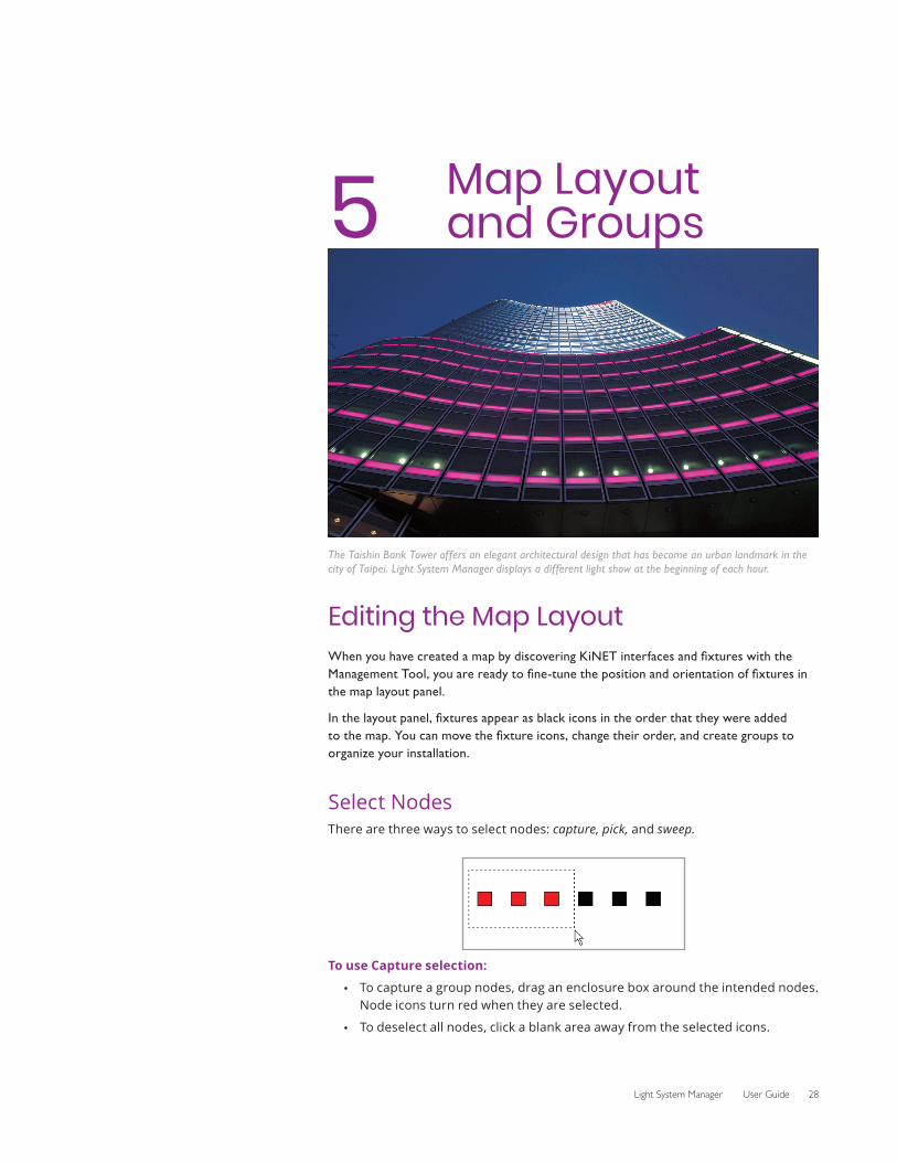
The Taishin Bank Tower offers an elegant architectural design that has become an urban landmark in the city of Taipei. Light System Manager displays a different light show at the beginning of each hour.
Editing the Map LayoutWhen you have created a map by discovering KiNET interfaces and fixtures with the Management Tool, you are ready to fine-tune the position and orientation of fixtures in the map layout panel.
In the layout panel, fixtures appear as black icons in the order that they were added to the map. You can move the fixture icons, change their order, and create groups to organize your installation.
Select NodesThere are three ways to select nodes: capture, pick, and sweep.
To use Capture selection:
• To capture a group nodes, drag an enclosure box around the intended nodes. Node icons turn red when they are selected.
• To deselect all nodes, click a blank area away from the selected icons.
29 Chapter 5
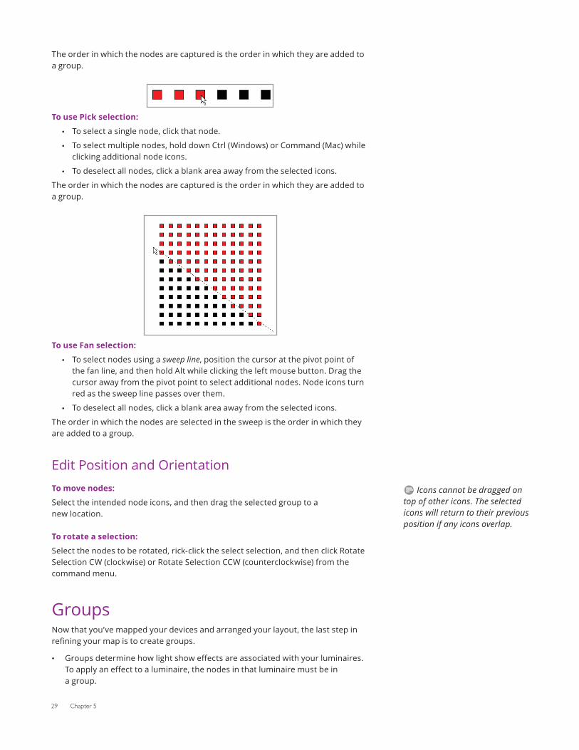
The order in which the nodes are captured is the order in which they are added to a group.
To use Pick selection:
• To select a single node, click that node.
• To select multiple nodes, hold down Ctrl (Windows) or Command (Mac) while clicking additional node icons.
• To deselect all nodes, click a blank area away from the selected icons.
The order in which the nodes are captured is the order in which they are added to a group.
To use Fan selection:
• To select nodes using a sweep line, position the cursor at the pivot point of the fan line, and then hold Alt while clicking the left mouse button. Drag the cursor away from the pivot point to select additional nodes. Node icons turn red as the sweep line passes over them.
• To deselect all nodes, click a blank area away from the selected icons.
The order in which the nodes are selected in the sweep is the order in which they are added to a group.
Edit Position and OrientationTo move nodes:
Select the intended node icons, and then drag the selected group to a new location.
To rotate a selection:
Select the nodes to be rotated, rick-click the select selection, and then click Rotate Selection CW (clockwise) or Rotate Selection CCW (counterclockwise) from the command menu.
GroupsNow that you’ve mapped your devices and arranged your layout, the last step in refining your map is to create groups.
• Groups determine how light show effects are associated with your luminaires. To apply an effect to a luminaire, the nodes in that luminaire must be in a group.
D Icons cannot be dragged on top of other icons. The selected icons will return to their previous position if any icons overlap.
Light System Manager User Guide 30
• There are two types of groups: synchronized groups and chasing groups. The order in which effects move across your nodes is determined by their group type.
Group type Description
Synchronized group
The nodes work in unison to display the same output.
Chasing group
Nodes in a chasing group work in series, in the order of their position within the group. For example, the first node in the group acts as fixture 1, the second node as fixture 2, and so on. Chasing groups enable animated effects to appear to chase from one node to another, then to another, and so on.
Create GroupsGroups are collections of nodes to which you can apply lighting effects. The group map editor and static scene creator in the LSE web interface apply effects to the groups you define in your map file. You must create a group for each collection of lights you want to control in Light System Composer Show Designer or in the LSE web interface.
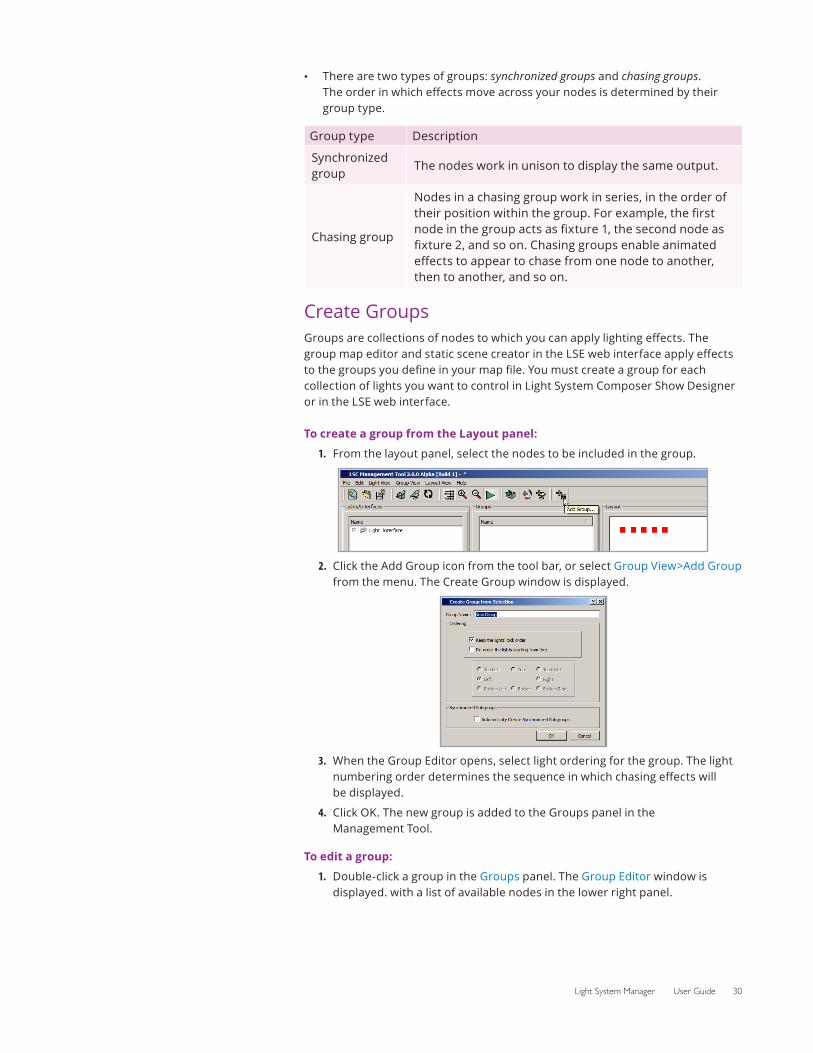
To create a group from the Layout panel:
1. From the layout panel, select the nodes to be included in the group.
2. Click the Add Group icon from the tool bar, or select Group View>Add Group from the menu. The Create Group window is displayed.
3. When the Group Editor opens, select light ordering for the group. The light numbering order determines the sequence in which chasing effects will be displayed.
4. Click OK. The new group is added to the Groups panel in the Management Tool.
To edit a group:
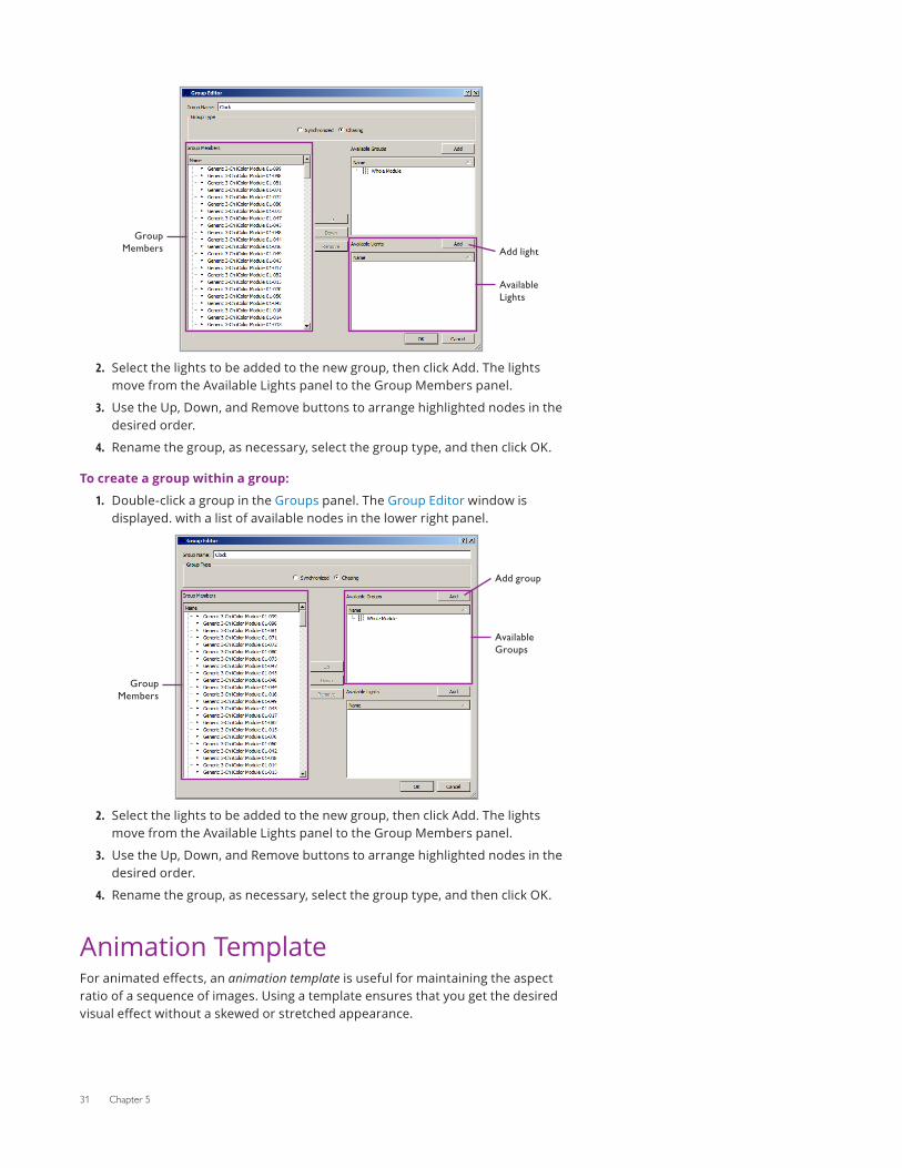
1. Double-click a group in the Groups panel. The Group Editor window is displayed. with a list of available nodes in the lower right panel.
31 Chapter 5
2.
Group Members Add light
Available Lights
Select the lights to be added to the new group, then click Add. The lights move from the Available Lights panel to the Group Members panel.
3. Use the Up, Down, and Remove buttons to arrange highlighted nodes in the desired order.
4. Rename the group, as necessary, select the group type, and then click OK.
To create a group within a group:
1. Double-click a group in the Groups panel. The Group Editor window is displayed. with a list of available nodes in the lower right panel.
2.
Group Members
Available Groups
Add group
Select the lights to be added to the new group, then click Add. The lights move from the Available Lights panel to the Group Members panel.
3. Use the Up, Down, and Remove buttons to arrange highlighted nodes in the desired order.
4. Rename the group, as necessary, select the group type, and then click OK.
Animation TemplateFor animated effects, an animation template is useful for maintaining the aspect ratio of a sequence of images. Using a template ensures that you get the desired visual effect without a skewed or stretched appearance.
Light System Manager User Guide 32
Grouping Nodes for an Animated EffectWhen grouping nodes for an animated effect, consider the desired visual effect. For example, if you want the animated effect to play on individual nodes, create separate groups for each node. If you are using a rectangular array of iColor Flex LMX gen2 and iColor Flex MX gen2 nodes configured as a single viewing surface, create a group that includes all of those nodes.
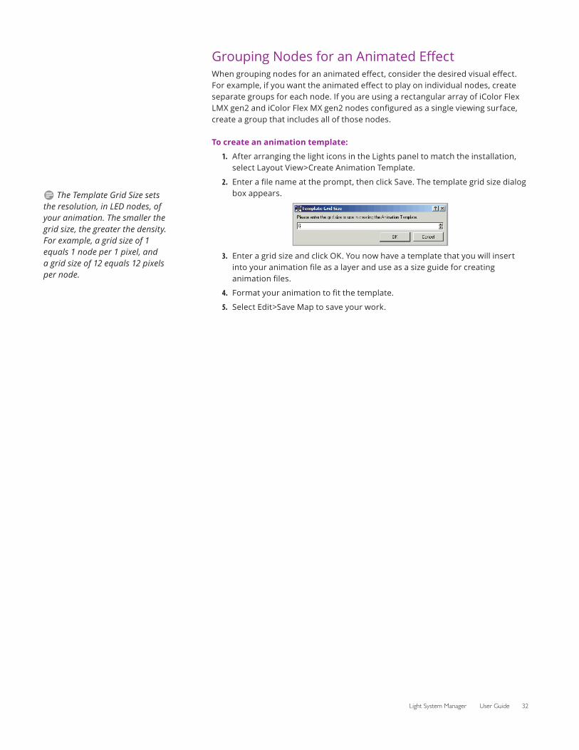
To create an animation template:
1. After arranging the light icons in the Lights panel to match the installation, select Layout View>Create Animation Template.
2. Enter a file name at the prompt, then click Save. The template grid size dialog box appears.
3. Enter a grid size and click OK. You now have a template that you will insert into your animation file as a layer and use as a size guide for creating animation files.
4. Format your animation to fit the template.
5. Select Edit>Save Map to save your work.
D The Template Grid Size sets the resolution, in LED nodes, of your animation. The smaller the grid size, the greater the density. For example, a grid size of 1 equals 1 node per 1 pixel, and a grid size of 12 equals 12 pixels per node.
Light System Manager User Guide 33
6 Creating Shows
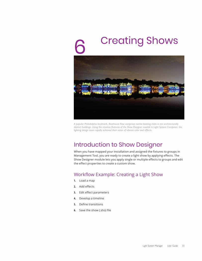
A popular Philadelphia landmark, Boathouse Row comprises twelve boating clubs in ten architecturally distinct buildings. Using the intuitive features of the Show Designer module in Light System Composer, the lighting design team rapidly achieved their vision of vibrant color and effects.
Introduction to Show DesignerWhen you have mapped your installation and assigned the fixtures to groups in Management Tool, you are ready to create a light show by applying effects. The Show Designer module lets you apply single or multiple effects to groups and edit the effect properties to create a custom show.
Workflow Example: Creating a Light Show1. Load a map
2. Add effects
3. Edit effect parameters
4. Develop a timeline
5. Define transitions
6. Save the show (.sho) file
34 Chapter 6
Launch Show DesignerTo launch Show Designer on Windows:
Select Start>All Programs>Color Kinetics>Light System Composer>Show Designer, or double-click Show Designer from the Color Kinetics Light System Composer folder installed on your desktop.
To launch Show Designer on macOS:
In Finder, navigate to /Applications/Color Kinetics/Light System Composer/ShowDesigner, and double-click ShowDesigner.app.
Create Shows
Load a Map
Before you can create a light show, you must create a map of the installation and arrange the fixtures into groups. If you have not created a map, use the Light System Composer Management Tool to either automatically map your installation or manually create a placeholder map. Placeholder maps are good tools for authoring practice shows and getting familiar with Light System Composer.
To load a map in Show Designer:
1. Launch Show Designer.
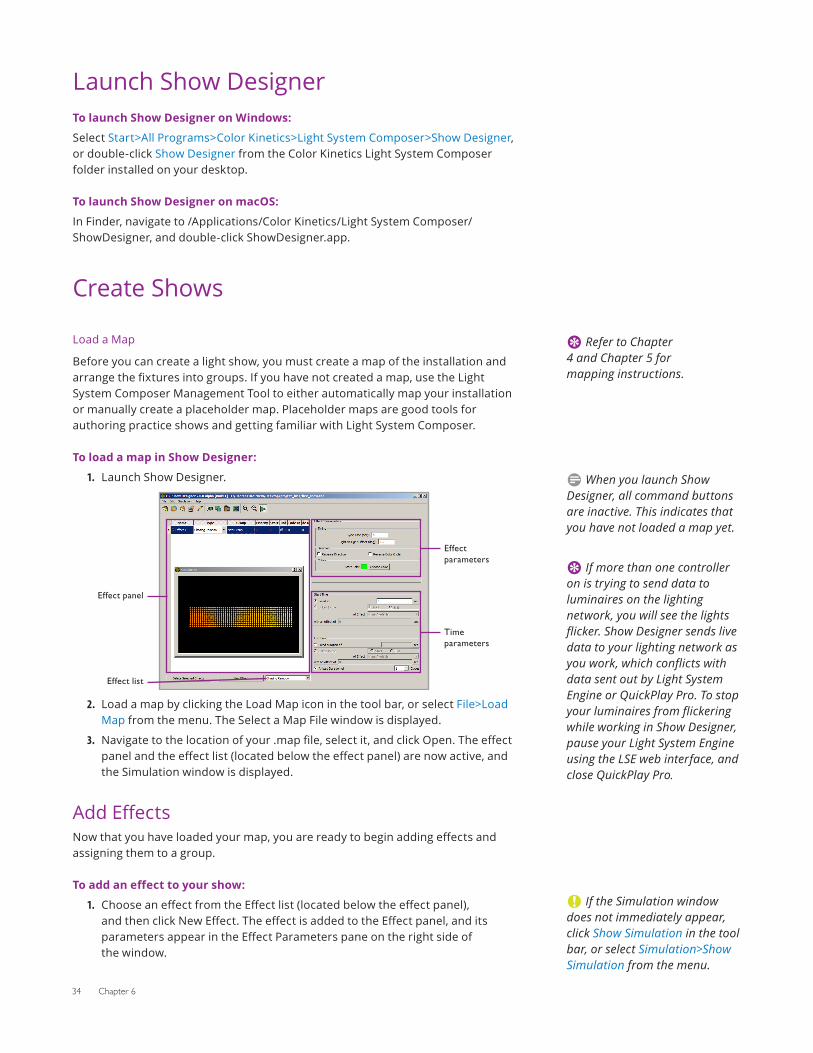
2.
Effect panel
Effect parameters
Time parameters
Effect list
Load a map by clicking the Load Map icon in the tool bar, or select File>Load Map from the menu. The Select a Map File window is displayed.
3. Navigate to the location of your .map file, select it, and click Open. The effect panel and the effect list (located below the effect panel) are now active, and the Simulation window is displayed.
Add EffectsNow that you have loaded your map, you are ready to begin adding effects and assigning them to a group.
To add an effect to your show:
1. Choose an effect from the Effect list (located below the effect panel), and then click New Effect. The effect is added to the Effect panel, and its parameters appear in the Effect Parameters pane on the right side of the window.
E Refer to Chapter 4 and Chapter 5 for mapping instructions.
D When you launch Show Designer, all command buttons are inactive. This indicates that you have not loaded a map yet.
E If more than one controller on is trying to send data to luminaires on the lighting network, you will see the lights flicker. Show Designer sends live data to your lighting network as you work, which conflicts with data sent out by Light System Engine or QuickPlay Pro. To stop your luminaires from flickering while working in Show Designer, pause your Light System Engine using the LSE web interface, and close QuickPlay Pro.
C If the Simulation window does not immediately appear, click Show Simulation in the tool bar, or select Simulation>Show Simulation from the menu.
Light System Manager User Guide 35
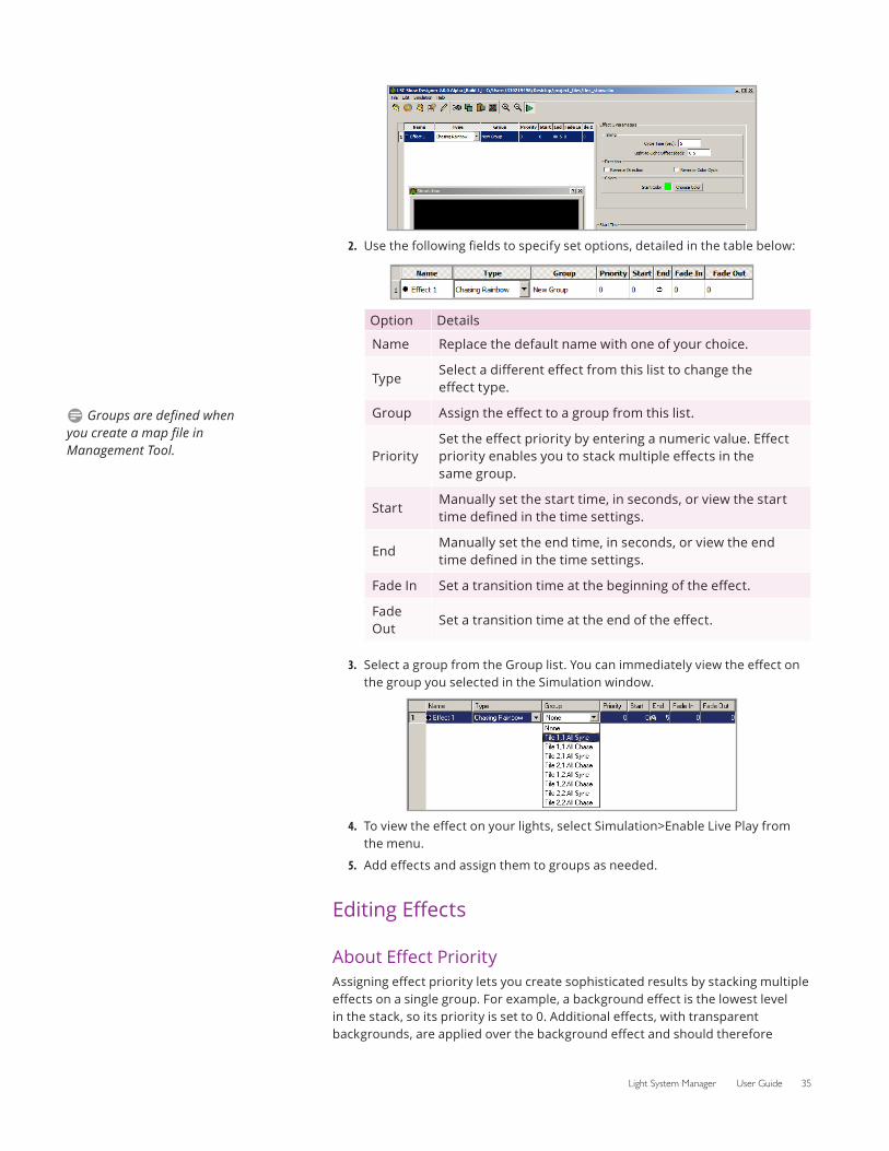
2. Use the following fields to specify set options, detailed in the table below:
Option Details
Name Replace the default name with one of your choice.
TypeSelect a different effect from this list to change the effect type.
Group Assign the effect to a group from this list.
PrioritySet the effect priority by entering a numeric value. Effect priority enables you to stack multiple effects in the same group.
StartManually set the start time, in seconds, or view the start time defined in the time settings.
EndManually set the end time, in seconds, or view the end time defined in the time settings.
Fade In Set a transition time at the beginning of the effect.
Fade Out
Set a transition time at the end of the effect.
3. Select a group from the Group list. You can immediately view the effect on the group you selected in the Simulation window.
4. To view the effect on your lights, select Simulation>Enable Live Play from the menu.
5. Add effects and assign them to groups as needed.
Editing Effects
About Effect PriorityAssigning effect priority lets you create sophisticated results by stacking multiple effects on a single group. For example, a background effect is the lowest level in the stack, so its priority is set to 0. Additional effects, with transparent backgrounds, are applied over the background effect and should therefore
D Groups are defined when you create a map file in Management Tool.
36 Chapter 6
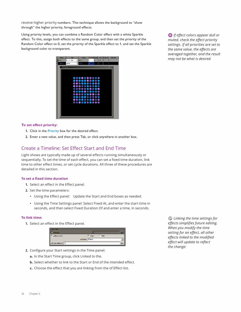
receive higher priority numbers. This technique allows the background to “show through” the higher priority, foreground effects.
Using priority levels, you can combine a Random Color effect with a white Sparkle effect. To this, assign both effects to the same group, and then set the priority of the Random Color effect to 0, set the priority of the Sparkle effect to 1, and set the Sparkle background color to transparent.
To set effect priority:1. Click in the Priority box for the desired effect.2. Enter a new value, and then press Tab, or click anywhere in another box.
Create a Timeline: Set Effect Start and End TimeLight shows are typically made up of several effects running simultaneously or sequentially. To set the time of each effect, you can set a fixed time duration, link time to other effect times, or set cycle durations. All three of these procedures are detailed in this section.
To set a fixed time duration
1. Select an effect in the Effect panel.
2. Set the time parameters:
• Using the Effect panel: Update the Start and End boxes as needed.
• Using the Time Settings panel: Select Fixed At, and enter the start time in seconds, and then select Fixed Duration Of and enter a time, in seconds.
To link time:
1. Select an effect in the Effect panel.
2. Configure your Start settings in the Time panel:
a. In the Start Time group, click Linked to the.
b. Select whether to link to the Start or End of the intended effect.
c. Choose the effect that you are linking from the of Effect list.
E If effect colors appear dull or muted, check the effect priority settings. If all priorities are set to the same value, the effects are averaged together, and the result may not be what is desired.
D Linking the time settings for effects simplifies future editing. When you modify the time setting for an effect, all other effects linked to the modified effect will update to reflect the change:
Light System Manager User Guide 37
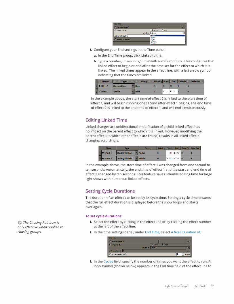
3. Configure your End settings in the Time panel:
a. In the End Time group, click Linked to the.
b. Type a number, in seconds, in the with an offset of box. This configures the linked effect to begin or end after the time set for the effect to which it is linked. The linked times appear in the effect line, with a left arrow symbol indicating that the times are linked.
In the example above, the start time of effect 2 is linked to the start time of effect 1, and will begin running one second after effect 1 begins. The end time of effect 2 is linked to the end time of effect 1, and will end simultaneously.
Editing Linked TimeLinked changes are unidirectional: modification of a child linked effect has no impact on the parent effect to which it is linked. However, modifying the parent effect (to which other effects are linked) results in all linked effects changing accordingly.
In the example above, the start time of effect 1 was changed from one second to ten seconds. Automatically, the end time of effect 1 and the start and end time of effect 2 changed by ten seconds. This feature saves valuable editing time for large light shows with numerous linked effects.
Setting Cycle DurationsThe duration of an effect can be set by its cycle time. Setting a cycle time ensures that the full effect duration is displayed before the show loops and starts over again.
To set cycle durations:
1. Select the effect by clicking in the effect line or by clicking the effect number at the left of the effect line.
2. In the time settings panel, under End Time, select A fixed Duration of.
3. In the Cycles field, specify the number of times you want the effect to run. A loop symbol (shown below) appears in the End time field of the effect line to
D The Chasing Rainbow is only effective when applied to chasing groups.
38 Chapter 6
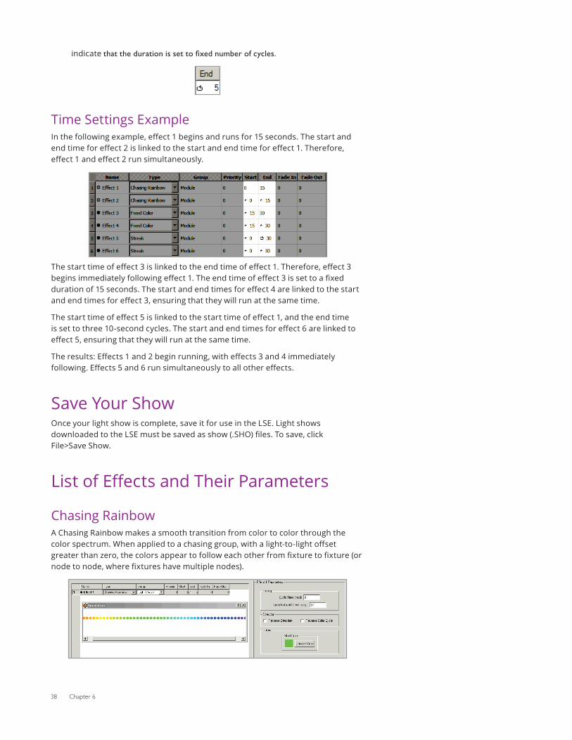
indicate that the duration is set to fixed number of cycles.
Time Settings ExampleIn the following example, effect 1 begins and runs for 15 seconds. The start and end time for effect 2 is linked to the start and end time for effect 1. Therefore, effect 1 and effect 2 run simultaneously.
The start time of effect 3 is linked to the end time of effect 1. Therefore, effect 3 begins immediately following effect 1. The end time of effect 3 is set to a fixed duration of 15 seconds. The start and end times for effect 4 are linked to the start and end times for effect 3, ensuring that they will run at the same time.
The start time of effect 5 is linked to the start time of effect 1, and the end time is set to three 10-second cycles. The start and end times for effect 6 are linked to effect 5, ensuring that they will run at the same time.
The results: Effects 1 and 2 begin running, with effects 3 and 4 immediately following. Effects 5 and 6 run simultaneously to all other effects.
Save Your ShowOnce your light show is complete, save it for use in the LSE. Light shows downloaded to the LSE must be saved as show (.SHO) files. To save, click File>Save Show.
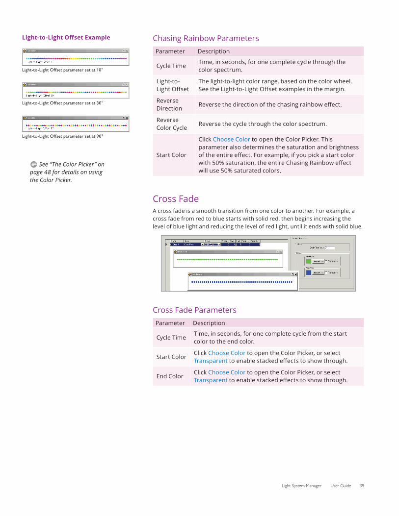
List of Effects and Their Parameters
Chasing RainbowA Chasing Rainbow makes a smooth transition from color to color through the color spectrum. When applied to a chasing group, with a light-to-light offset greater than zero, the colors appear to follow each other from fixture to fixture (or node to node, where fixtures have multiple nodes).
Light System Manager User Guide 39
Chasing Rainbow ParametersParameter Description
Cycle TimeTime, in seconds, for one complete cycle through the color spectrum.
Light-to-Light Offset
The light-to-light color range, based on the color wheel. See the Light-to-Light Offset examples in the margin.
Reverse Direction
Reverse the direction of the chasing rainbow effect.
Reverse Color Cycle
Reverse the cycle through the color spectrum.
Start Color
Click Choose Color to open the Color Picker. This parameter also determines the saturation and brightness of the entire effect. For example, if you pick a start color with 50% saturation, the entire Chasing Rainbow effect will use 50% saturated colors.
Cross FadeA cross fade is a smooth transition from one color to another. For example, a cross fade from red to blue starts with solid red, then begins increasing the level of blue light and reducing the level of red light, until it ends with solid blue.
Cross Fade ParametersParameter Description
Cycle TimeTime, in seconds, for one complete cycle from the start color to the end color.
Start ColorClick Choose Color to open the Color Picker, or select Transparent to enable stacked effects to show through.
End ColorClick Choose Color to open the Color Picker, or select Transparent to enable stacked effects to show through.
Light-to-Light Offset Example
Light-to-Light Offset parameter set at 10°
Light-to-Light Offset parameter set at 30°
Light-to-Light Offset parameter set at 90°
D See “The Color Picker” on page 48 for details on using the Color Picker.
40 Chapter 6
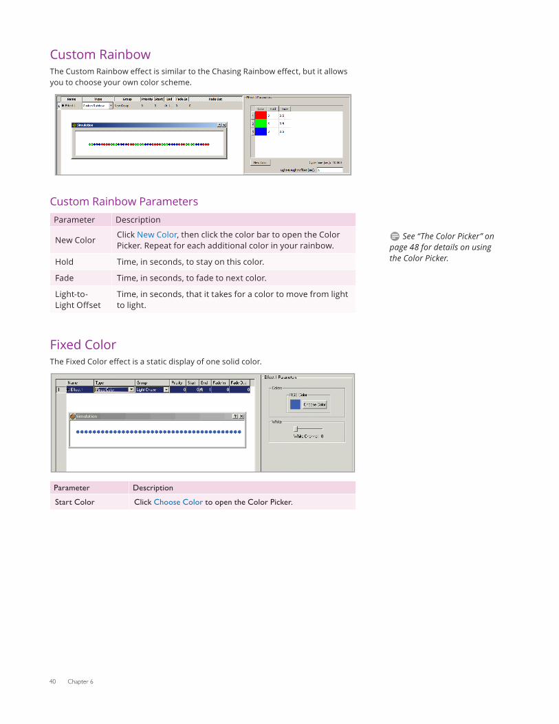
Custom RainbowThe Custom Rainbow effect is similar to the Chasing Rainbow effect, but it allows you to choose your own color scheme.
Custom Rainbow ParametersParameter Description
New ColorClick New Color, then click the color bar to open the Color Picker. Repeat for each additional color in your rainbow.
Hold Time, in seconds, to stay on this color.
Fade Time, in seconds, to fade to next color.
Light-to-Light Offset
Time, in seconds, that it takes for a color to move from light to light.
Fixed ColorThe Fixed Color effect is a static display of one solid color.
Parameter Description
Start Color Click Choose Color to open the Color Picker.
D See “The Color Picker” on page 48 for details on using the Color Picker.
Light System Manager User Guide 41
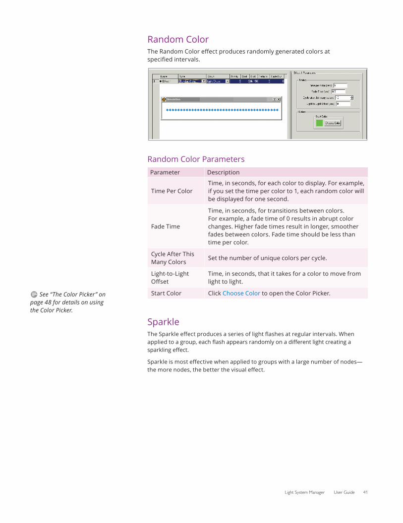
Random ColorThe Random Color effect produces randomly generated colors at specified intervals.
Random Color ParametersParameter Description
Time Per ColorTime, in seconds, for each color to display. For example, if you set the time per color to 1, each random color will be displayed for one second.
Fade Time
Time, in seconds, for transitions between colors. For example, a fade time of 0 results in abrupt color changes. Higher fade times result in longer, smoother fades between colors. Fade time should be less than time per color.
Cycle After This Many Colors
Set the number of unique colors per cycle.
Light-to-Light Offset
Time, in seconds, that it takes for a color to move from light to light.
Start Color Click Choose Color to open the Color Picker.
SparkleThe Sparkle effect produces a series of light flashes at regular intervals. When applied to a group, each flash appears randomly on a different light creating a sparkling effect.
Sparkle is most effective when applied to groups with a large number of nodes—the more nodes, the better the visual effect.
D See “The Color Picker” on page 48 for details on using the Color Picker.
42 Chapter 6
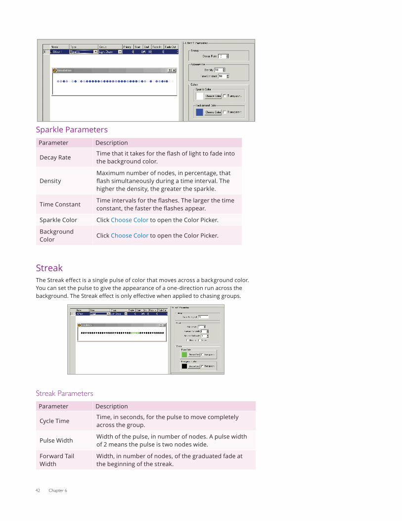
Sparkle ParametersParameter Description
Decay RateTime that it takes for the flash of light to fade into the background color.
DensityMaximum number of nodes, in percentage, that flash simultaneously during a time interval. The higher the density, the greater the sparkle.
Time ConstantTime intervals for the flashes. The larger the time constant, the faster the flashes appear.
Sparkle Color Click Choose Color to open the Color Picker.
Background Color
Click Choose Color to open the Color Picker.
StreakThe Streak effect is a single pulse of color that moves across a background color. You can set the pulse to give the appearance of a one-direction run across the background. The Streak effect is only effective when applied to chasing groups.
Streak ParametersParameter Description
Cycle TimeTime, in seconds, for the pulse to move completely across the group.
Pulse WidthWidth of the pulse, in number of nodes. A pulse width of 2 means the pulse is two nodes wide.
Forward Tail Width
Width, in number of nodes, of the graduated fade at the beginning of the streak.
Light System Manager User Guide 43
Parameter Description
Reverse Tail Width
Width, in number of nodes, of the graduated fade at the end of the streak.
Reverse Reverse the direction of the Pulse effect.
WrapSelect this option to have a pulse begin in the same graduated increments as the previous pulse is ending, creating a wrapping effect.
Pulse ColorClick Choose Color to open the Color Picker, or select Transparent.
Background Color
Click Choose Color to open the Color Picker, or select Transparent.
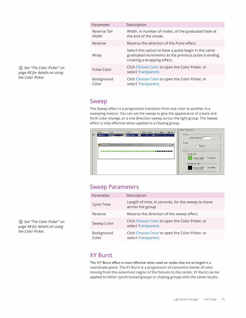
SweepThe Sweep effect is a progressive transition from one color to another in a sweeping motion. You can set the sweep to give the appearance of a back and forth color change, or a one direction sweep across the light group. The Sweep effect is only effective when applied to a chasing group.
Sweep ParametersParameter Description
Cycle TimeLength of time, in seconds, for the sweep to move across the group.
Reverse Reverse the direction of the sweep effect.
Sweep ColorClick Choose Color to open the Color Picker, or select Transparent.
Background Color
Click Choose Color to open the Color Picker, or select Transparent.
XY BurstThe XY Burst effect is most effective when used on nodes that are arranged in a coordinate plane. The XY Burst is a progression of concentric bands of color moving from the outermost region of the fixtures to the center. XY Burst can be applied to either synchronized groups or chasing groups with the same results.
D See “The Color Picker” on page 48 for details on using the Color Picker.
D See “The Color Picker” on page 48 for details on using the Color Picker.
44 Chapter 6
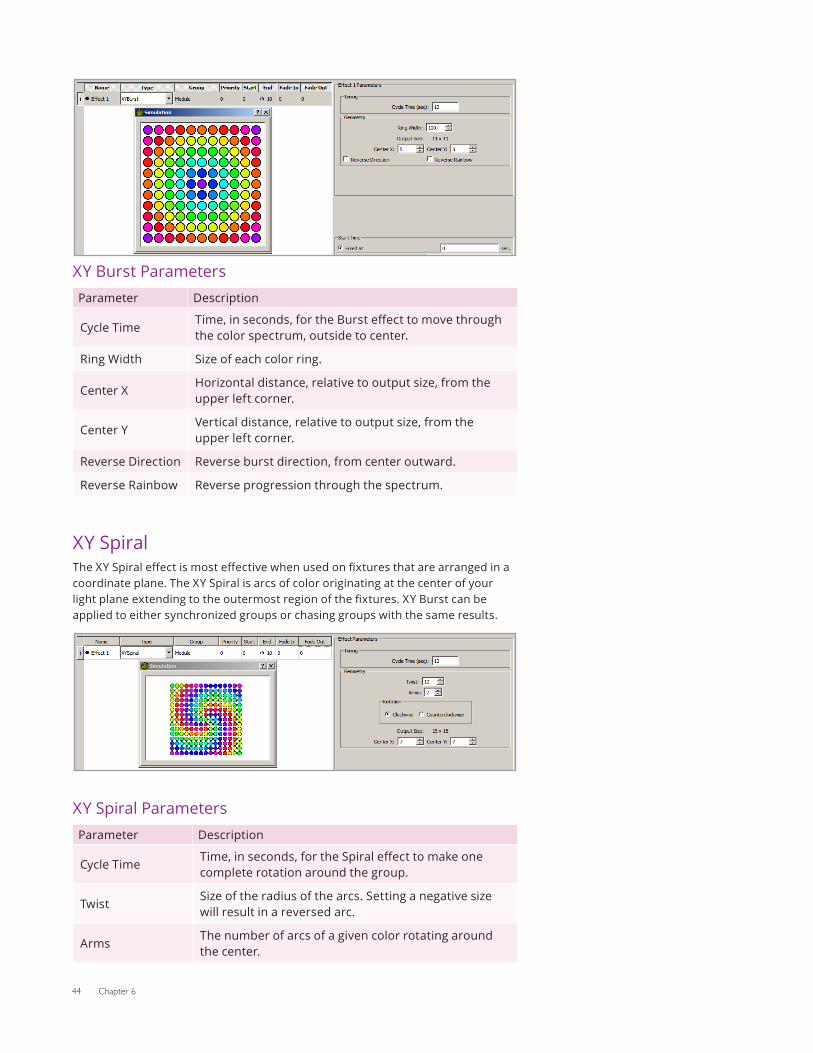
XY Burst ParametersParameter Description
Cycle TimeTime, in seconds, for the Burst effect to move through the color spectrum, outside to center.
Ring Width Size of each color ring.
Center XHorizontal distance, relative to output size, from the upper left corner.
Center YVertical distance, relative to output size, from the upper left corner.
Reverse Direction Reverse burst direction, from center outward.
Reverse Rainbow Reverse progression through the spectrum.
XY SpiralThe XY Spiral effect is most effective when used on fixtures that are arranged in a coordinate plane. The XY Spiral is arcs of color originating at the center of your light plane extending to the outermost region of the fixtures. XY Burst can be applied to either synchronized groups or chasing groups with the same results.
XY Spiral ParametersParameter Description
Cycle TimeTime, in seconds, for the Spiral effect to make one complete rotation around the group.
TwistSize of the radius of the arcs. Setting a negative size will result in a reversed arc.
ArmsThe number of arcs of a given color rotating around the center.
Light System Manager User Guide 45
Parameter Description
Clockwise/Counterclockwise
Rotational direction of the spiral.
Center XHorizontal distance, relative to output size, from the upper left corner.
Center YVertical distance, relative to output size, from the upper left corner.
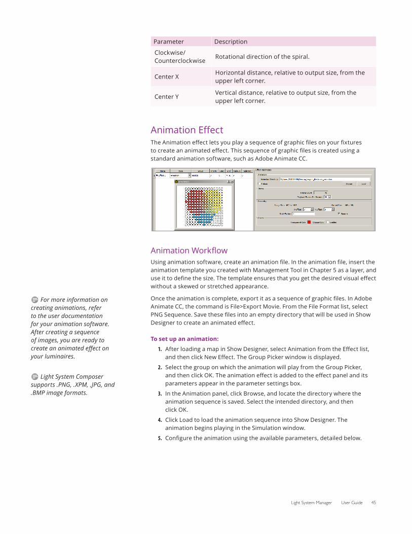
Animation EffectThe Animation effect lets you play a sequence of graphic files on your fixtures to create an animated effect. This sequence of graphic files is created using a standard animation software, such as Adobe Animate CC.
Animation WorkflowUsing animation software, create an animation file. In the animation file, insert the animation template you created with Management Tool in Chapter 5 as a layer, and use it to define the size. The template ensures that you get the desired visual effect without a skewed or stretched appearance.
Once the animation is complete, export it as a sequence of graphic files. In Adobe Animate CC, the command is File>Export Movie. From the File Format list, select PNG Sequence. Save these files into an empty directory that will be used in Show Designer to create an animated effect.
To set up an animation:
1. After loading a map in Show Designer, select Animation from the Effect list, and then click New Effect. The Group Picker window is displayed.
2. Select the group on which the animation will play from the Group Picker, and then click OK. The animation effect is added to the effect panel and its parameters appear in the parameter settings box.
3. In the Animation panel, click Browse, and locate the directory where the animation sequence is saved. Select the intended directory, and then click OK.
4. Click Load to load the animation sequence into Show Designer. The animation begins playing in the Simulation window.
5. Configure the animation using the available parameters, detailed below.
D For more information on creating animations, refer to the user documentation for your animation software. After creating a sequence of images, you are ready to create an animated effect on your luminaires.
D Light System Composer supports .PNG, .XPM, .JPG, and .BMP image formats.
46 Chapter 6
Animation ParametersParameter Description
Preload
Playback Frames Per Second
Playback speed of the animation.
X OffsetDistance from the left side that the image appears. A positive X Offset will shift the image to the right, while a negative X Offset will shift the image to the left.
Y OffsetDistance from the top side that the image appears. A positive Y Offset will shift the image up, while a negative Y Offset will shift the image down.
Scale FactorSize of the animation on the group. The larger this number, the smaller the image.
Smooth Soften the hard edges in the animation.
Transparent Color
Transparent color background. To set, click Choose Color to open the Color Picker, and select the Enabled check box.
Image ScrollImage Scroll allows you to move a still image across a grid of fixtures. The Image Scroll effect is ideal for iColor Flex LMX gen2 or eW Flex Compact nodes installed in a grid pattern.
To create an Image Scroll effect:
1. After loading a map in Show Designer, select Image Scroll from the Effect list, and then click New Effect. The Group Picker window is displayed.
2. Select the group on which the image scroll will play from the Group Picker, and then click OK. The image scroll effect is added to the effect panel, and its parameters appear in the parameter settings box.
3. In the Image panel, click Browse, and locate the directory where the animation sequence is saved. Select the intended directory, and then click OK.
4. Click Load to load the image sequence into Show Designer. The scroll begins playing in the Simulation window.
5. Configure the image scroll using the available parameters, detailed below.
D See “The Color Picker” on page 48 for details on using the Color Picker.
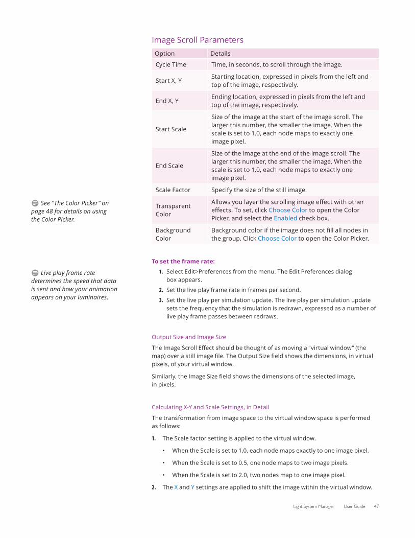
Light System Manager User Guide 47
Image Scroll ParametersOption Details
Cycle Time Time, in seconds, to scroll through the image.
Start X, YStarting location, expressed in pixels from the left and top of the image, respectively.
End X, YEnding location, expressed in pixels from the left and top of the image, respectively.
Start Scale
Size of the image at the start of the image scroll. The larger this number, the smaller the image. When the scale is set to 1.0, each node maps to exactly one image pixel.
End Scale
Size of the image at the end of the image scroll. The larger this number, the smaller the image. When the scale is set to 1.0, each node maps to exactly one image pixel.
Scale Factor Specify the size of the still image.
Transparent Color
Allows you layer the scrolling image effect with other effects. To set, click Choose Color to open the Color Picker, and select the Enabled check box.
Background Color
Background color if the image does not fill all nodes in the group. Click Choose Color to open the Color Picker.
To set the frame rate:
1. Select Edit>Preferences from the menu. The Edit Preferences dialog box appears.
2. Set the live play frame rate in frames per second.
3. Set the live play per simulation update. The live play per simulation update sets the frequency that the simulation is redrawn, expressed as a number of live play frame passes between redraws.
Output Size and Image Size
The Image Scroll Effect should be thought of as moving a “virtual window” (the map) over a still image file. The Output Size field shows the dimensions, in virtual pixels, of your virtual window.
Similarly, the Image Size field shows the dimensions of the selected image, in pixels.
Calculating X-Y and Scale Settings, in Detail
The transformation from image space to the virtual window space is performed as follows:
1. The Scale factor setting is applied to the virtual window.
• When the Scale is set to 1.0, each node maps exactly to one image pixel.
• When the Scale is set to 0.5, one node maps to two image pixels.
• When the Scale is set to 2.0, two nodes map to one image pixel.
2. The X and Y settings are applied to shift the image within the virtual window.
D See “The Color Picker” on page 48 for details on using the Color Picker.
D Live play frame rate determines the speed that data is sent and how your animation appears on your luminaires.
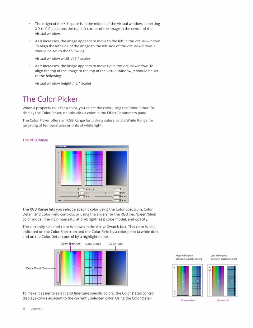
48 Chapter 6
• The origin of the X-Y space is in the middle of the virtual window, so setting X-Y to 0,0 positions the top left corner of the image in the center of the virtual window.
• As X increases, the image appears to move to the left in the virtual window. To align the left side of the image to the left side of the virtual window, X should be set to the following:
virtual window width / (2 * scale)
• As Y increases, the image appears to move up in the virtual window. To align the top of the image to the top of the virtual window, Y should be set to the following:
virtual window height / (2 * scale)
The Color PickerWhen a property calls for a color, you select the color using the Color Picker. To display the Color Picker, double-click a color in the Effect Parameters pane.
The Color Picker offers an RGB Range for picking colors, and a White Range for targeting of temperatures or tints of white light.
The RGB Range
The RGB Range lets you select a specific color using the Color Spectrum, Color Detail, and Color Field controls, or using the sliders for the RGB (red/green/blue) color model, the HSV (hue/saturation/brightness) color model, and opacity.
The currently selected color is shown in the Active Swatch box. This color is also indicated on the Color Spectrum and the Color Field by a color point (a white dot), and on the Color Detail control by a highlighted box.
Color Spectrum Color Detail Color Field
Color Detail Zoom
To make it easier to select and fine-tune specific colors, the Color Detail control displays colors adjacent to the currently selected color. Using the Color Detail Zoomed in
Less difference between adjacent colors
Zoomed out
More difference between adjacent colors
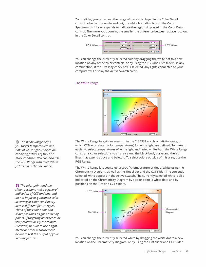
Light System Manager User Guide 49
Zoom slider, you can adjust the range of colors displayed in the Color Detail control. When you zoom in and out, the white bounding box on the Color Spectrum shrinks or expands to indicate the region displayed in the Color Detail control. The more you zoom in, the smaller the difference between adjacent colors in the Color Detail control.
RGB Sliders HSV Sliders
You can change the currently selected color by dragging the white dot to a new location on any of the color controls, or by using the RGB and HSV sliders, in any combination. If the Live Play check box is selected, any lights connected to your computer will display the Active Swatch color.
The White Range
The White Range targets an area within the CIE 1931 x-y chromaticity space, on which CCTs (correlated color temperatures) for white light are defined. To make it easier to select temperatures of white light and tinted white light, the White Range constrains color selections to an area along the black-body curve and the iso lines that extend above and below it. To select colors outside of this area, use the RGB Range.
The White Range lets you select a specific temperature or tint of white using the Chromaticity Diagram, as well as the Tint slider and the CCT slider. The currently selected white appears in the Active Swatch. The currently selected white is also indicated on the Chromaticity Diagram by a color point (a white dot), and by positions on the Tint and CCT sliders.
CCT Slider
Tint SliderChromaticity Diagram
You can change the currently selected white by dragging the white dot to a new location on the Chromaticity Diagram, or by using the Tint slider and CCT slider,
D The White Range helps you target temperatures and tints of white light using color-changing fixtures of three or more channels. You can also use the RGB Range with IntelliWhite fixtures in 3-channel mode.
E The color point and the slider positions make a general indication of CCT and tint, and do not imply or guarantee color accuracy or color consistency across different fixture types. Think of the color point and slider positions as good starting points. If targeting an exact color temperature or x-y coordinate is critical, be sure to use a light meter or other measurement device to test the output of your lighting fixtures.
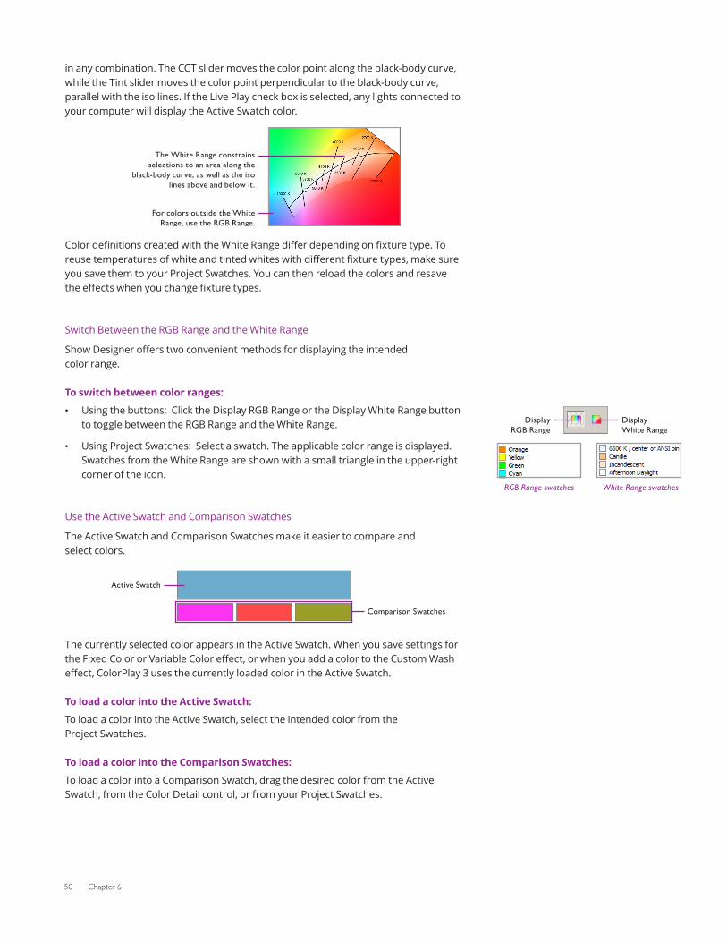
50 Chapter 6
in any combination. The CCT slider moves the color point along the black-body curve, while the Tint slider moves the color point perpendicular to the black-body curve, parallel with the iso lines. If the Live Play check box is selected, any lights connected to your computer will display the Active Swatch color.
Color
The White Range constrains selections to an area along the
black-body curve, as well as the iso lines above and below it.
For colors outside the White Range, use the RGB Range.
definitions created with the White Range differ depending on fixture type. To reuse temperatures of white and tinted whites with different fixture types, make sure you save them to your Project Swatches. You can then reload the colors and resave the effects when you change fixture types.
Switch Between the RGB Range and the White Range
Show Designer offers two convenient methods for displaying the intended color range.
To switch between color ranges:
• Using the buttons: Click the Display RGB Range or the Display White Range button to toggle between the RGB Range and the White Range.
• Using Project Swatches: Select a swatch. The applicable color range is displayed. Swatches from the White Range are shown with a small triangle in the upper-right corner of the icon.
Use the Active Swatch and Comparison Swatches
The Active Swatch and Comparison Swatches make it easier to compare and select colors.
Active Swatch
Comparison Swatches
The currently selected color appears in the Active Swatch. When you save settings for the Fixed Color or Variable Color effect, or when you add a color to the Custom Wash effect, ColorPlay 3 uses the currently loaded color in the Active Swatch.
To load a color into the Active Swatch:
To load a color into the Active Swatch, select the intended color from the Project Swatches.
To load a color into the Comparison Swatches:
To load a color into a Comparison Swatch, drag the desired color from the Active Swatch, from the Color Detail control, or from your Project Swatches.
Display RGB Range
Display White Range
RGB Range swatches White Range swatches
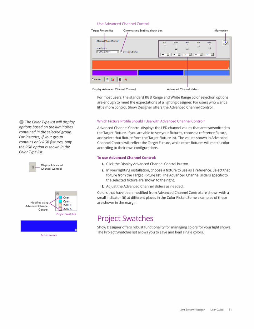
Light System Manager User Guide 51
Use Advanced Channel Control
Chromasync Enabled check box Information
Advanced Channel slidersDisplay Advanced Channel Control
Target Fixture list
For most users, the standard RGB Range and White Range color selection options are enough to meet the expectations of a lighting designer. For users who want a little more control, Show Designer offers the Advanced Channel Control.
Which Fixture Profile Should I Use with Advanced Channel Control?
Advanced Channel Control displays the LED channel values that are transmitted to the Target Fixture. If you are able to see your fixtures, choose a reference fixture, and select that fixture from the Target Fixture list. The values shown in Advanced Channel Control will reflect the Target Fixture, while other fixtures will match color according to their own configurations.
To use Advanced Channel Control:
1. Click the Display Advanced Channel Control button.
2. In your lighting installation, choose a fixture to use as a reference. Select that fixture from the Target Fixture list. The Advanced Channel sliders specific to the selected fixture are shown to the right.
3. Adjust the Advanced Channel sliders as needed.
Colors that have been modified from Advanced Channel Control are shown with a small indicator ( ) at different places in the Color Picker. Some examples of these are shown in the margin.
Project SwatchesShow Designer offers robust functionality for managing colors for your light shows. The Project Swatches list allows you to save and load single colors.
D The Color Type list will display options based on the luminaires contained in the selected group. For instance, if your group contains only RGB fixtures, only the RGB option is shown in the Color Type list.
Display Advanced Channel Control
Active Swatch
Project Swatches
Modified using Advanced Channel
Control
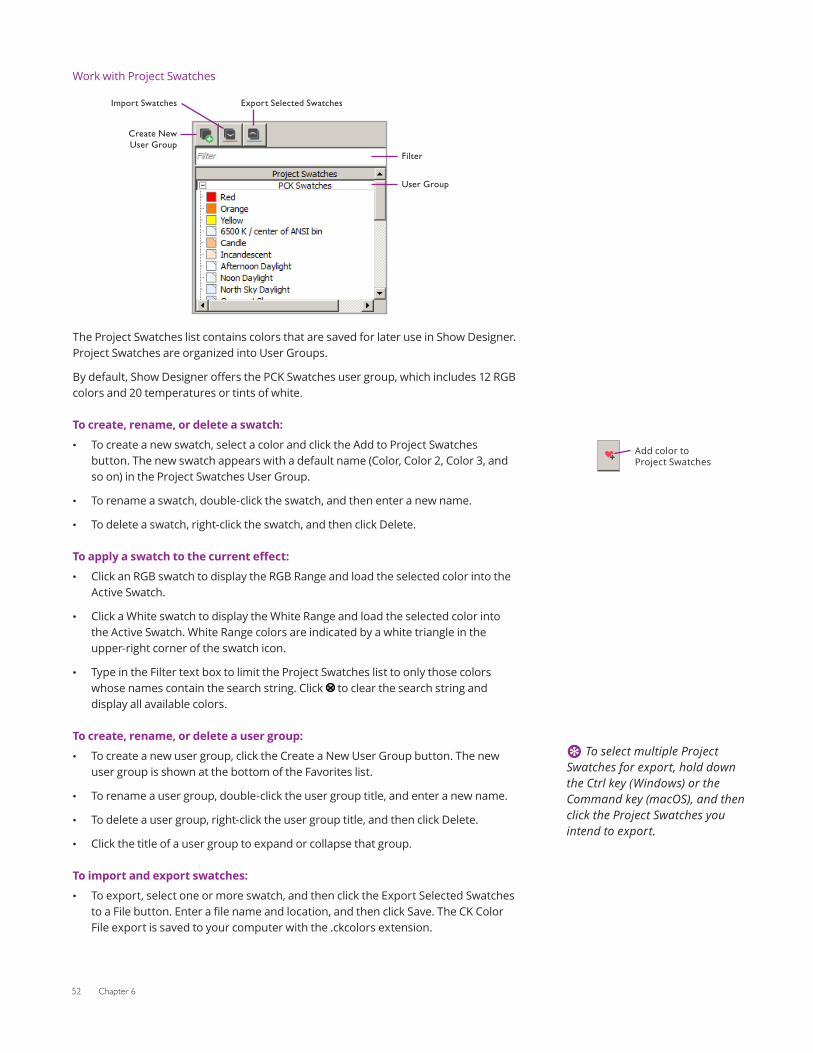
52 Chapter 6
Work with Project Swatches
Export Selected SwatchesImport Swatches
User Group
Create New User Group
Filter
The Project Swatches list contains colors that are saved for later use in Show Designer. Project Swatches are organized into User Groups.
By default, Show Designer offers the PCK Swatches user group, which includes 12 RGB colors and 20 temperatures or tints of white.
To create, rename, or delete a swatch:
• To create a new swatch, select a color and click the Add to Project Swatches button. The new swatch appears with a default name (Color, Color 2, Color 3, and so on) in the Project Swatches User Group.
• To rename a swatch, double-click the swatch, and then enter a new name.
• To delete a swatch, right-click the swatch, and then click Delete.
To apply a swatch to the current effect:
• Click an RGB swatch to display the RGB Range and load the selected color into the Active Swatch.
• Click a White swatch to display the White Range and load the selected color into the Active Swatch. White Range colors are indicated by a white triangle in the upper-right corner of the swatch icon.
• Type in the Filter text box to limit the Project Swatches list to only those colors whose names contain the search string. Click to clear the search string and display all available colors.
To create, rename, or delete a user group:
• To create a new user group, click the Create a New User Group button. The new user group is shown at the bottom of the Favorites list.
• To rename a user group, double-click the user group title, and enter a new name.
• To delete a user group, right-click the user group title, and then click Delete.
• Click the title of a user group to expand or collapse that group.
To import and export swatches:
• To export, select one or more swatch, and then click the Export Selected Swatches to a File button. Enter a file name and location, and then click Save. The CK Color File export is saved to your computer with the .ckcolors extension.
Add color to Project Swatches
E To select multiple Project Swatches for export, hold down the Ctrl key (Windows) or the Command key (macOS), and then click the Project Swatches you intend to export.
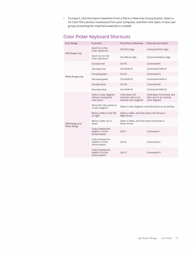
Light System Manager User Guide 53
• To import, click the Import Swatches From a File to a New User Group button. Select a CK Color File (.ckcolors extension) from your computer, and then click Open. A new user group containing the imported swatches is created.
Color Picker Keyboard ShortcutsColor Range To do this Press this on Windows Press this on macOS
RGB Range only
Zoom in on the Color Spectrum Ctrl+Plus Sign Command+Plus Sign
Zoom out on the Color Spectrum Ctrl+Minus Sign Command+Minus Sign
White Range only
Increase red Ctrl+R Command+R
Decrease red Ctrl+Shift+R Command+Shift+R
Increase green Ctrl+G Command+G
Decrease green Ctrl+Shift+G Command+Shift+G
Increase blue Ctrl+B Command+B
Decrease blue Ctrl+Shift+B Command+Shift+B
RGB Range and White Range
Select a color diagram without moving the color point
Hold down Ctrl, and then click in an inactive color diagram
Hold down Command, and then click in an inactive color diagram
Move the color point on a color diagram Select a color diagram, and then press an arrow key
Move a slider to the left or right
Select a slider, and then press Left Arrow or Right Arrow
Move a slider up or down
Select a slider, and then press Up Arrow or Down Arrow
Copy Comparison Swatch 1 to the Active Swatch
Ctrl+1 Command+1
Copy Comparison Swatch 2 to the Active Swatch
Ctrl+2 Command+2
Copy Comparison Swatch 3 to the Active Swatch
Ctrl+3 Command+3

54 Chapter 6
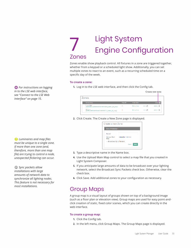
Light System Manager User Guide 55
7 Light System Engine Configuration
ZonesZones enable show playback control. All fixtures in a zone are triggered together, whether from a keypad or a scheduled light show. Additionally, you can set multiple zones to react to an event, such as a recurring scheduled time on a specific day of the week.
To create a zone:
1. Log in to the LSE web interface, and then click the Config tab.
2.
Create new zone
Click Create. The Create a New Zone page is displayed.
3. Type a descriptive name in the Name box.
4. Use the Upload Main Map control to select a map file that you created in Light System Composer.
5. If you anticipate large amounts of data to be broadcast over your lighting network, select the Broadcast Sync Packets check box. Otherwise, clear the check box.
6. Click Save. Add additional zones to your configuration as necessary.
Group MapsA group map is a visual layout of groups shown on top of a background image (such as a floor plan or elevation view). Group maps are used for easy point-and-click creation of static, fixed color scenes, which you can create directly in the web interface.
To create a group map:
1. Click the Config tab.
2. In the left menu, click Group Maps. The Group Maps page is displayed.
E For instructions on logging in to the LSE web interface, see “Connect to the LSE Web Interface” on page 15.
C Luminaires and map files must be unique to a single zone. If more than one zone (and, therefore, more than one map file) are trying to control a node, unexpected flickering can occur.
D Sync packets allow installations with large amounts of network data to synchronize all lighting nodes. This feature is not necessary for most installations.
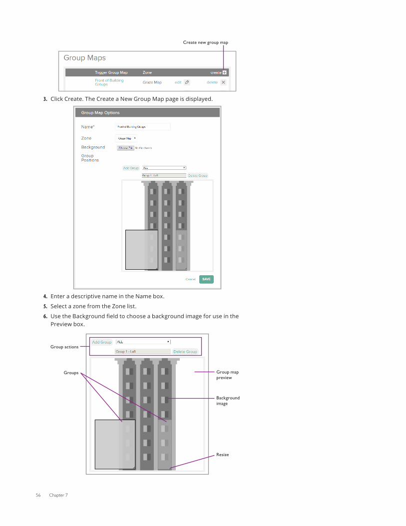
56 Chapter 7
3.
Create new group map
Click Create. The Create a New Group Map page is displayed.
4. Enter a descriptive name in the Name box.
5. Select a zone from the Zone list.
6. Use the Background field to choose a background image for use in the Preview box.
Group actions
Groups Group map preview
Background image
Resize
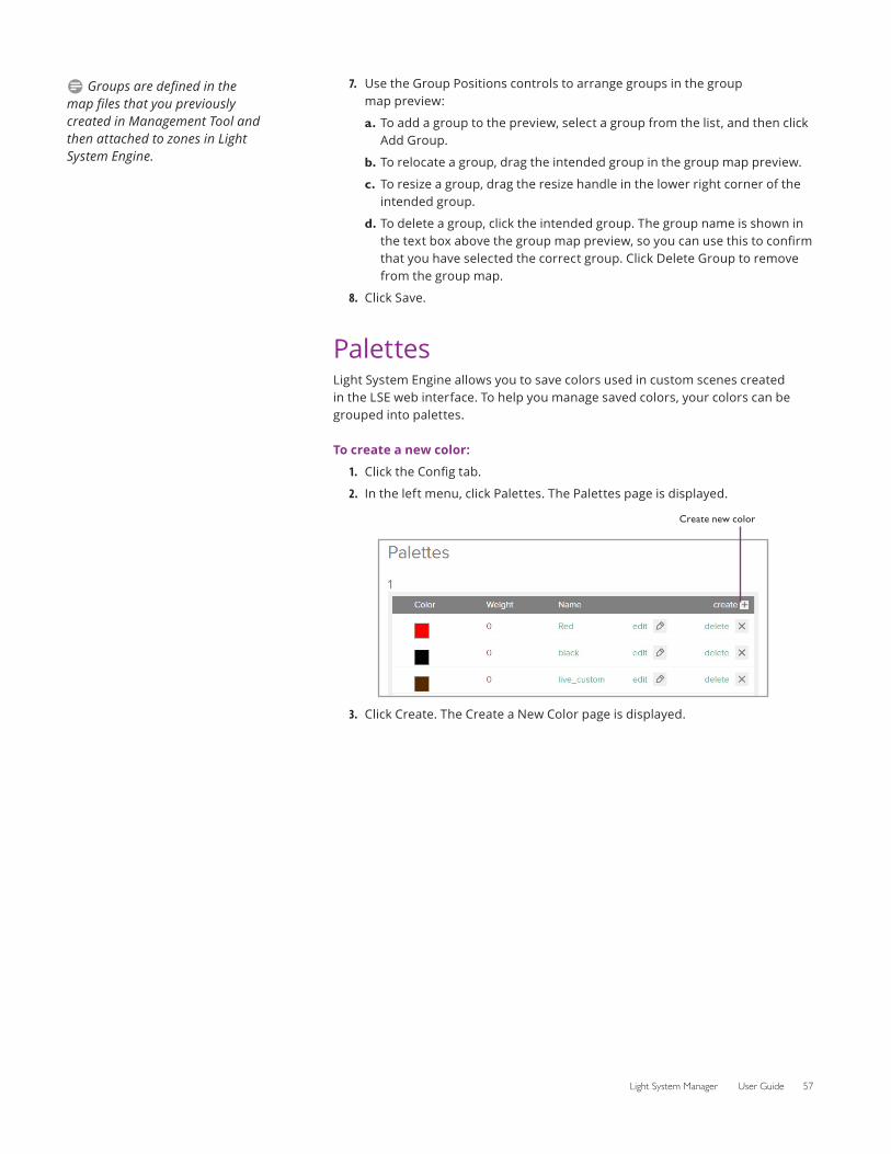
Light System Manager User Guide 57
7. Use the Group Positions controls to arrange groups in the group map preview:
a. To add a group to the preview, select a group from the list, and then click Add Group.
b. To relocate a group, drag the intended group in the group map preview.
c. To resize a group, drag the resize handle in the lower right corner of the intended group.
d. To delete a group, click the intended group. The group name is shown in the text box above the group map preview, so you can use this to confirm that you have selected the correct group. Click Delete Group to remove from the group map.
8. Click Save.
PalettesLight System Engine allows you to save colors used in custom scenes created in the LSE web interface. To help you manage saved colors, your colors can be grouped into palettes.
To create a new color:
1. Click the Config tab.
2. In the left menu, click Palettes. The Palettes page is displayed.
Create new color
3. Click Create. The Create a New Color page is displayed.
D Groups are defined in the map files that you previously created in Management Tool and then attached to zones in Light System Engine.
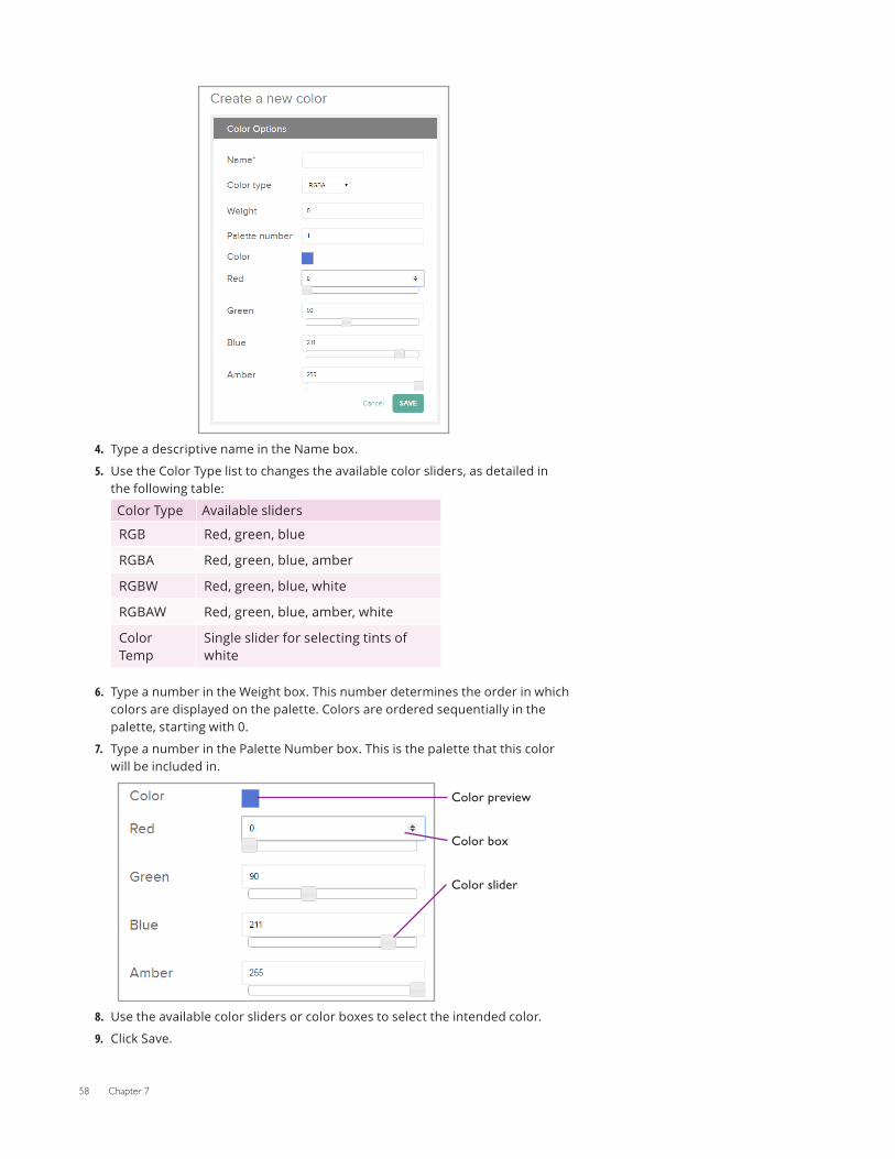
58 Chapter 7
4. Type a descriptive name in the Name box.
5. Use the Color Type list to changes the available color sliders, as detailed in the following table:
Color Type Available sliders
RGB Red, green, blue
RGBA Red, green, blue, amber
RGBW Red, green, blue, white
RGBAW Red, green, blue, amber, white
Color Temp
Single slider for selecting tints of white
6. Type a number in the Weight box. This number determines the order in which colors are displayed on the palette. Colors are ordered sequentially in the palette, starting with 0.
7. Type a number in the Palette Number box. This is the palette that this color will be included in.
8.
Color slider
Color preview
Color box
Use the available color sliders or color boxes to select the intended color.
9. Click Save.
Light System Manager User Guide 59
Manage ColorsTo modify a color:
1. Locate the color in the Palettes configuration page, and click Edit.
2. Change the settings as needed, and then click Save.
To delete a color:
Locate the color in the Palettes configuration page, and click Delete.
Manage Palettes
Palettes are created based on the settings of each saved color. The Palette Number setting controls which palette a color belongs to, while the Weight setting controls the sort order of colors in each palette.
To move a color to a different palette:
1. Locate the intended color in the Palettes configuration page, and click Edit.
2. Type a number in the Palette Number box. To move the color to a new Palette, type a palette number that does not exist yet.
3. Click Save.
To change the sort order of colors in a palette:
1. Locate the intended color in the Palettes configuration page, and click Edit.
2. Type a number in the Weight box. Type 0 to place a color at the top of the palette. Palettes are sorted by weight, in ascending order.
3. Click Save.
To delete a palette:
To delete a palette, move or delete all colors in that palette.
KeypadsLight System Engine can trigger events using three types of keypads: a serial keypad, a broadcast keypad (Remote Keypad app), or Ethernet keypads. You can configure one serial keypad, one broadcast keypad, and up to 10 Ethernet keypads. The serial keypad supports up to 225 buttons. Serial button events can be triggered using an AuxBox, a Color Kinetics Controller Keypad, or a compatible third party system.
Add KeypadsTo add a serial keypad or remoate app keypad:
1. Click the Config tab.
2. In the left menu, click Keypads. The Keypad Configuration page is displayed.
3. Click Create in the keypad type that you want to create (Serial Keypad or Remote App Keypad).
4. Enter a descriptive Name for this keypad.
5. Click Save. To configure your keypad, see the “Configure Keypads” section below.
D To configure a third party serial controller, refer to Appendix D for the serial keypad protocol.
E Using an AuxBox in your installation lets you trigger shows via contact closure switches such as motion detectors and electronic eyes.
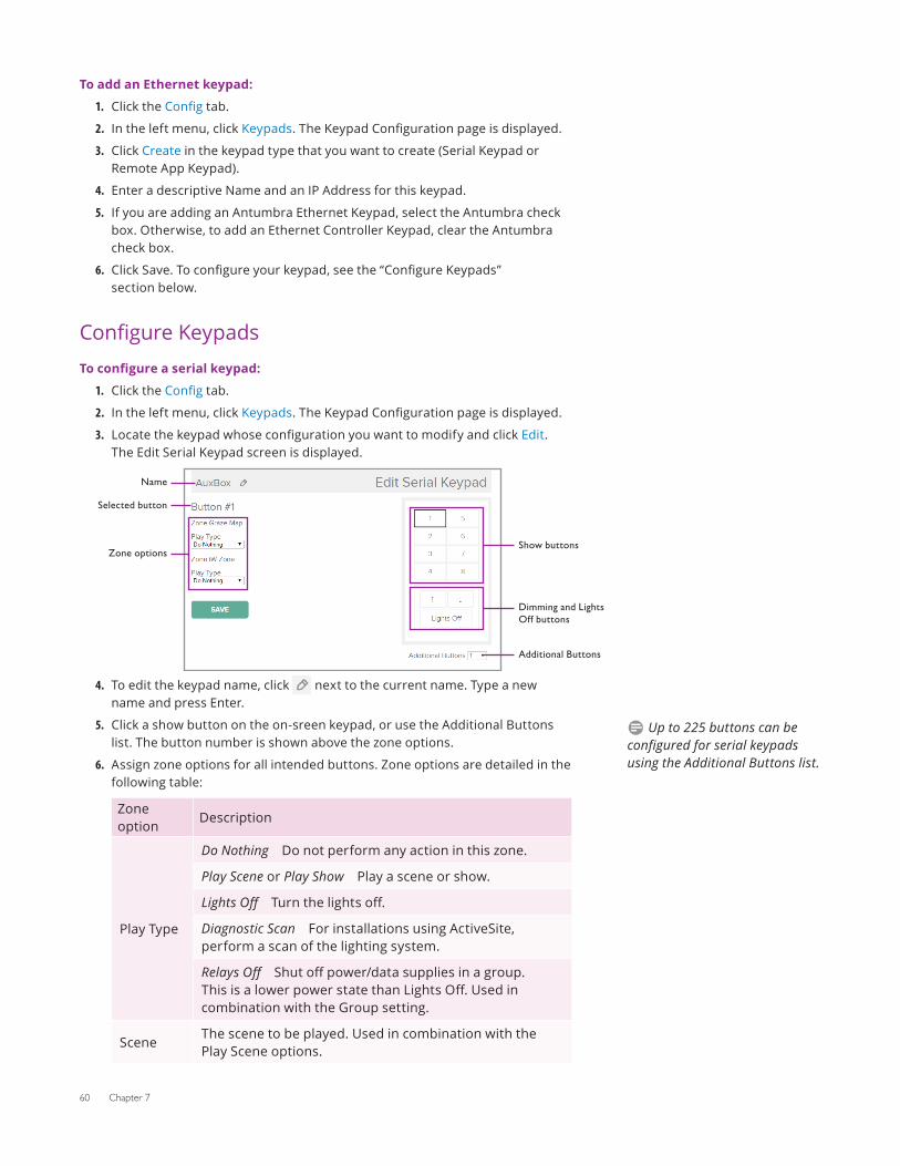
60 Chapter 7
To add an Ethernet keypad:
1. Click the Config tab.
2. In the left menu, click Keypads. The Keypad Configuration page is displayed.
3. Click Create in the keypad type that you want to create (Serial Keypad or Remote App Keypad).
4. Enter a descriptive Name and an IP Address for this keypad.
5. If you are adding an Antumbra Ethernet Keypad, select the Antumbra check box. Otherwise, to add an Ethernet Controller Keypad, clear the Antumbra check box.
6. Click Save. To configure your keypad, see the “Configure Keypads” section below.
Configure KeypadsTo configure a serial keypad:
1. Click the Config tab.
2. In the left menu, click Keypads. The Keypad Configuration page is displayed.
3. Locate the keypad whose configuration you want to modify and click Edit. The Edit Serial Keypad screen is displayed.
4.
Additional Buttons
Show buttons
Dimming and Lights Off buttons
Name
Selected button
Zone options
To edit the keypad name, click next to the current name. Type a new name and press Enter.
5. Click a show button on the on-sreen keypad, or use the Additional Buttons list. The button number is shown above the zone options.
6. Assign zone options for all intended buttons. Zone options are detailed in the following table:
Zone option
Description
Play Type
Do Nothing Do not perform any action in this zone.
Play Scene or Play Show Play a scene or show.
Lights Off Turn the lights off.
Diagnostic Scan For installations using ActiveSite, perform a scan of the lighting system.
Relays Off Shut off power/data supplies in a group. This is a lower power state than Lights Off. Used in combination with the Group setting.
SceneThe scene to be played. Used in combination with the Play Scene options.
D Up to 225 buttons can be configured for serial keypads using the Additional Buttons list.
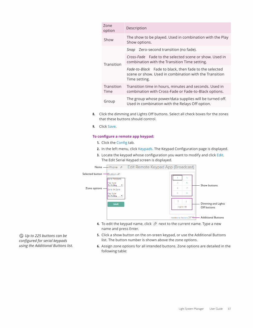
Light System Manager User Guide 61
Zone option
Description
ShowThe show to be played. Used in combination with the Play Show options.
Transition
Snap Zero-second transition (no fade).
Cross-Fade Fade to the selected scene or show. Used in combination with the Transition Time setting.
Fade-to-Black Fade to black, then fade to the selected scene or show. Used in combination with the Transition Time setting.
Transition Time
Transition time in hours, minutes and seconds. Used in combination with Cross-Fade or Fade-to-Black options.
GroupThe group whose power/data supplies will be turned off. Used in combination with the Relays Off option.
8. Click the dimming and Lights Off buttons. Select all check boxes for the zones that these buttons should control.
9. Click Save.
To configure a remote app keypad:
1. Click the Config tab.
2. In the left menu, click Keypads. The Keypad Configuration page is displayed.
3. Locate the keypad whose configuration you want to modify and click Edit. The Edit Serial Keypad screen is displayed.
4.
Name
Selected button
Zone optionsShow buttons
Dimming and Lights Off buttons
Additional Buttons
To edit the keypad name, click next to the current name. Type a new name and press Enter.
5. Click a show button on the on-sreen keypad, or use the Additional Buttons list. The button number is shown above the zone options.
6. Assign zone options for all intended buttons. Zone options are detailed in the following table:
D Up to 225 buttons can be configured for serial keypads using the Additional Buttons list.
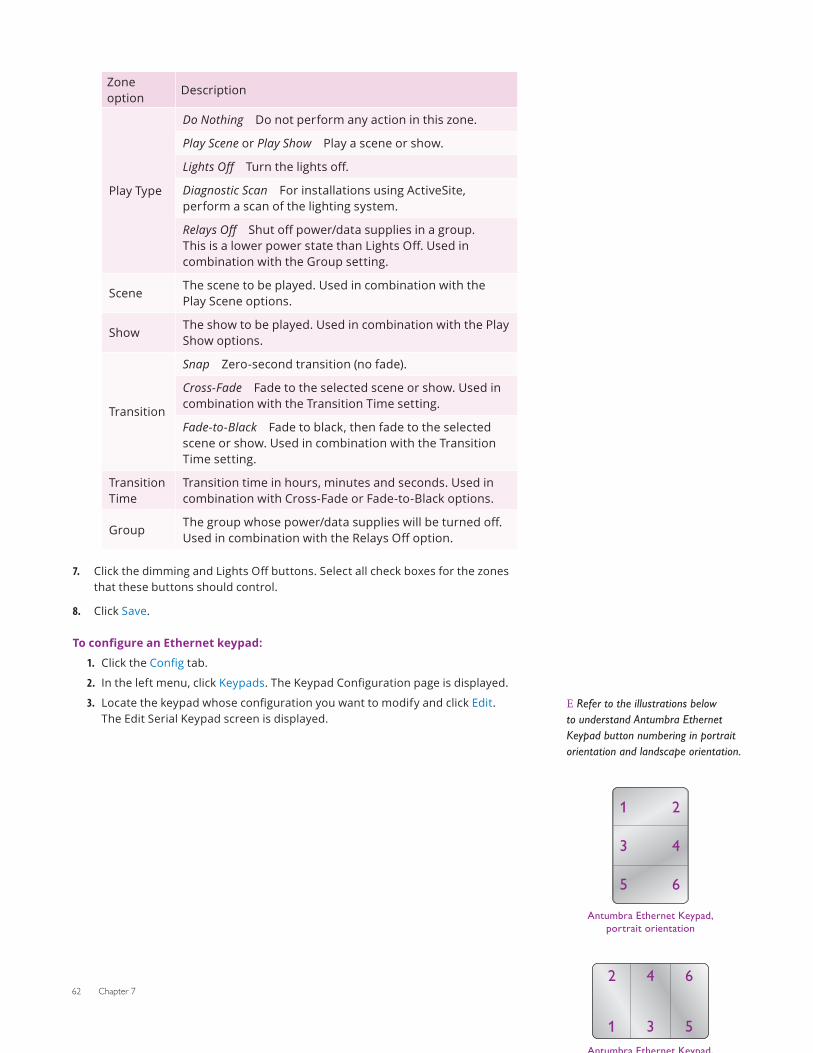
62 Chapter 7
Zone option
Description
Play Type
Do Nothing Do not perform any action in this zone.
Play Scene or Play Show Play a scene or show.
Lights Off Turn the lights off.
Diagnostic Scan For installations using ActiveSite, perform a scan of the lighting system.
Relays Off Shut off power/data supplies in a group. This is a lower power state than Lights Off. Used in combination with the Group setting.
SceneThe scene to be played. Used in combination with the Play Scene options.
ShowThe show to be played. Used in combination with the Play Show options.
Transition
Snap Zero-second transition (no fade).
Cross-Fade Fade to the selected scene or show. Used in combination with the Transition Time setting.
Fade-to-Black Fade to black, then fade to the selected scene or show. Used in combination with the Transition Time setting.
Transition Time
Transition time in hours, minutes and seconds. Used in combination with Cross-Fade or Fade-to-Black options.
GroupThe group whose power/data supplies will be turned off. Used in combination with the Relays Off option.
7. Click the dimming and Lights Off buttons. Select all check boxes for the zones that these buttons should control.
8. Click Save.
To configure an Ethernet keypad:
1. Click the Config tab.
2. In the left menu, click Keypads. The Keypad Configuration page is displayed.
3. Locate the keypad whose configuration you want to modify and click Edit. The Edit Serial Keypad screen is displayed.
E Refer to the illustrations below to understand Antumbra Ethernet Keypad button numbering in portrait orientation and landscape orientation.
Antumbra Ethernet Keypad, portrait orientation
2
4
6
1
3
5
Antumbra Ethernet Keypad, landscape orientation
2 4 6
1 3 5
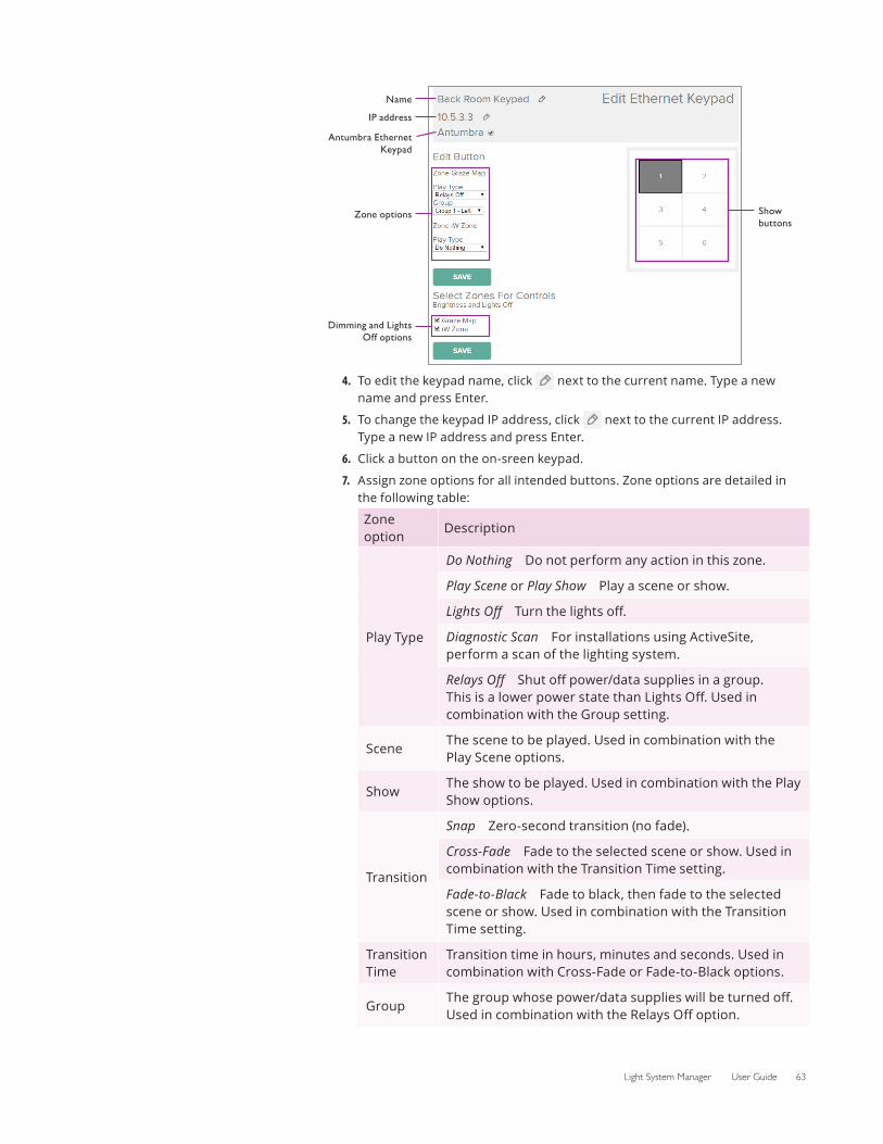
Light System Manager User Guide 63
4.
Show buttons
Name
IP address
Zone options
Dimming and Lights Off options
Antumbra Ethernet Keypad
To edit the keypad name, click next to the current name. Type a new name and press Enter.
5. To change the keypad IP address, click next to the current IP address. Type a new IP address and press Enter.
6. Click a button on the on-sreen keypad.
7. Assign zone options for all intended buttons. Zone options are detailed in the following table:
Zone option
Description
Play Type
Do Nothing Do not perform any action in this zone.
Play Scene or Play Show Play a scene or show.
Lights Off Turn the lights off.
Diagnostic Scan For installations using ActiveSite, perform a scan of the lighting system.
Relays Off Shut off power/data supplies in a group. This is a lower power state than Lights Off. Used in combination with the Group setting.
SceneThe scene to be played. Used in combination with the Play Scene options.
ShowThe show to be played. Used in combination with the Play Show options.
Transition
Snap Zero-second transition (no fade).
Cross-Fade Fade to the selected scene or show. Used in combination with the Transition Time setting.
Fade-to-Black Fade to black, then fade to the selected scene or show. Used in combination with the Transition Time setting.
Transition Time
Transition time in hours, minutes and seconds. Used in combination with Cross-Fade or Fade-to-Black options.
GroupThe group whose power/data supplies will be turned off. Used in combination with the Relays Off option.
64 Chapter 7
8. If you are configuring Ethernet Controller Keypad: Click the dimming and Lights Off buttons. Select all check boxes for the zones that these buttons should control. If you are configuring Antumbra Ethernet Keypad: Select the check boxes for the zones that should be controlled by Lights Off and dimming functions. In order to use dimming controls, enable this functionality on your Antumbra Ethernet Keypad using QuickPlay Pro. QuickPlay Pro is available from Color Kinetics at www.colorkinetics.com/support/addressing/.
9. Click Save.
Trigger an ActiveSite Diagnostic ScanUsers can manually trigger a diagnostic scan of lighting installations that use ActiveSite to detect and identify of all the devices on the lighting network.
To trigger a diagnostic scan:
1. Click the Config tab. The configuration page is displayed.
2. In the left menu, click ActiveSite, and then click Scan Now.
Light System Engine LogsLight System Engine logs allow admin users to view detailed system information and recent history. There are three types of logs: Frontend, Shows, and Backend.
Log type Details
Frontend All actions taken by users.
Shows History of all triggered events, separated by zone.
BackendDiagnostic information useful for advanced troubleshooting by Color Kinetics Support Representatives.
System SettingsLight System Engine offers additional options, detailed below, that will allow you to further customize default behaviors.
Global TransitionsThis setting affects how shows will play when you trigger them from the Zones tab.
To change your default Global Transition:
1. Click the Config tab.
2. In the left menu, select Settings>Global Transitions.
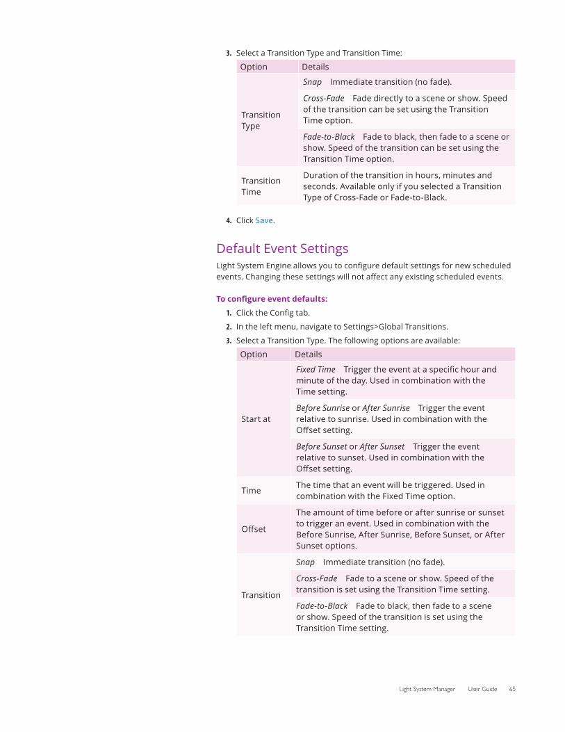
Light System Manager User Guide 65
3. Select a Transition Type and Transition Time:
Option Details
Transition Type
Snap Immediate transition (no fade).
Cross-Fade Fade directly to a scene or show. Speed of the transition can be set using the Transition Time option.
Fade-to-Black Fade to black, then fade to a scene or show. Speed of the transition can be set using the Transition Time option.
Transition Time
Duration of the transition in hours, minutes and seconds. Available only if you selected a Transition Type of Cross-Fade or Fade-to-Black.
4. Click Save.
Default Event SettingsLight System Engine allows you to configure default settings for new scheduled events. Changing these settings will not affect any existing scheduled events.
To configure event defaults:
1. Click the Config tab.
2. In the left menu, navigate to Settings>Global Transitions.
3. Select a Transition Type. The following options are available:
Option Details
Start at
Fixed Time Trigger the event at a specific hour and minute of the day. Used in combination with the Time setting.
Before Sunrise or After Sunrise Trigger the event relative to sunrise. Used in combination with the Offset setting.
Before Sunset or After Sunset Trigger the event relative to sunset. Used in combination with the Offset setting.
TimeThe time that an event will be triggered. Used in combination with the Fixed Time option.
Offset
The amount of time before or after sunrise or sunset to trigger an event. Used in combination with the Before Sunrise, After Sunrise, Before Sunset, or After Sunset options.
Transition
Snap Immediate transition (no fade).
Cross-Fade Fade to a scene or show. Speed of the transition is set using the Transition Time setting.
Fade-to-Black Fade to black, then fade to a scene or show. Speed of the transition is set using the Transition Time setting.
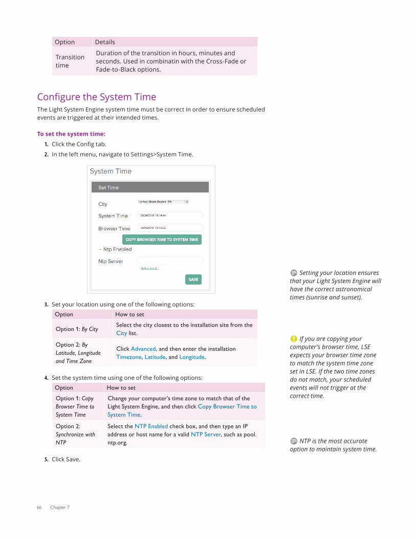
66 Chapter 7
Option Details
Transition time
Duration of the transition in hours, minutes and seconds. Used in combinatin with the Cross-Fade or Fade-to-Black options.
Configure the System TimeThe Light System Engine system time must be correct in order to ensure scheduled events are triggered at their intended times.
To set the system time:
1. Click the Config tab.
2. In the left menu, navigate to Settings>System Time.
3. Set your location using one of the following options:
Option How to set
Option 1: By City Select the city closest to the installation site from the City list.
Option 2: By Latitude, Longitude and Time Zone
Click Advanced, and then enter the installation Timezone, Latitude, and Longitude.
4. Set the system time using one of the following options:
Option How to set
Option 1: Copy Browser Time to System Time
Change your computer’s time zone to match that of the Light System Engine, and then click Copy Browser Time to System Time.
Option 2: Synchronize with NTP
Select the NTP Enabled check box, and then type an IP address or host name for a valid NTP Server, such as pool.ntp.org.
5. Click Save.
D Setting your location ensures that your Light System Engine will have the correct astronomical times (sunrise and sunset).
C If you are copying your computer’s browser time, LSE expects your browser time zone to match the system time zone set in LSE. If the two time zones do not match, your scheduled events will not trigger at the correct time.
D NTP is the most accurate option to maintain system time.
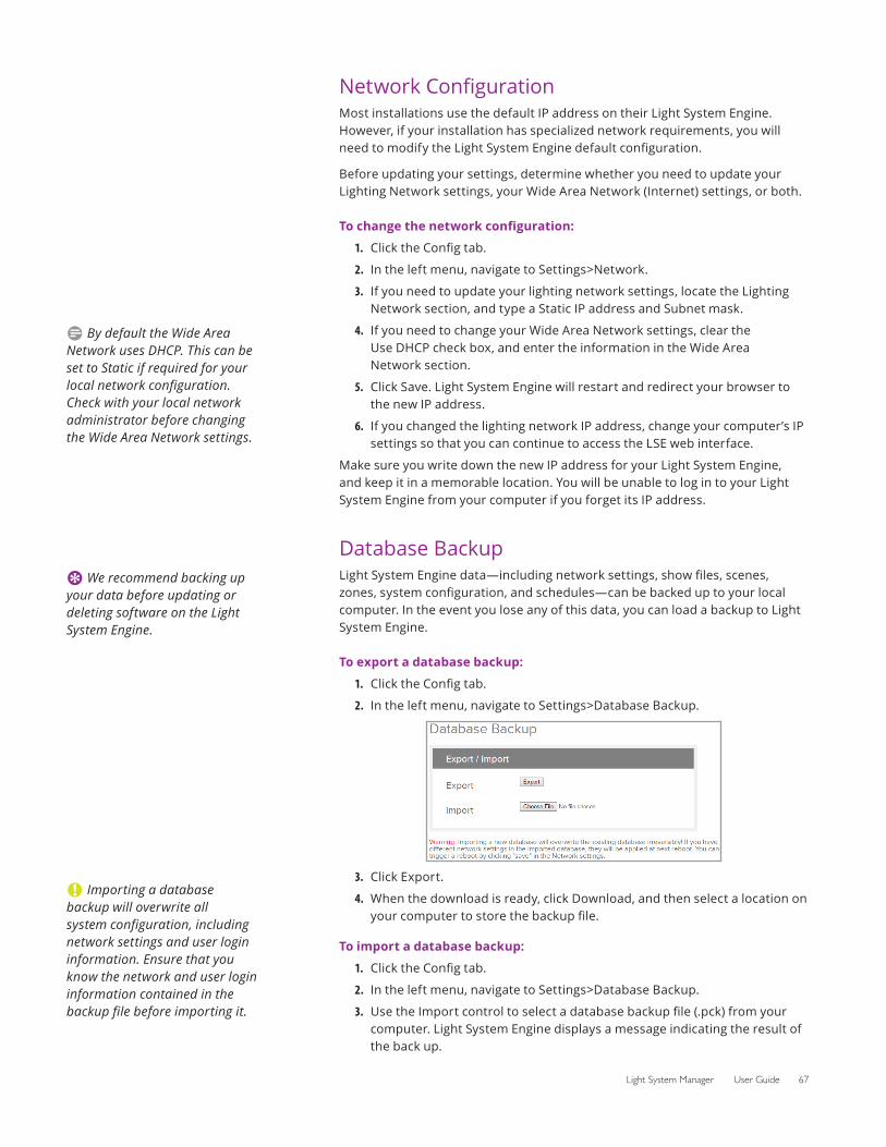
Light System Manager User Guide 67
Network ConfigurationMost installations use the default IP address on their Light System Engine. However, if your installation has specialized network requirements, you will need to modify the Light System Engine default configuration.
Before updating your settings, determine whether you need to update your Lighting Network settings, your Wide Area Network (Internet) settings, or both.
To change the network configuration:
1. Click the Config tab.
2. In the left menu, navigate to Settings>Network.
3. If you need to update your lighting network settings, locate the Lighting Network section, and type a Static IP address and Subnet mask.
4. If you need to change your Wide Area Network settings, clear the Use DHCP check box, and enter the information in the Wide Area Network section.
5. Click Save. Light System Engine will restart and redirect your browser to the new IP address.
6. If you changed the lighting network IP address, change your computer’s IP settings so that you can continue to access the LSE web interface.
Make sure you write down the new IP address for your Light System Engine, and keep it in a memorable location. You will be unable to log in to your Light System Engine from your computer if you forget its IP address.
Database BackupLight System Engine data—including network settings, show files, scenes, zones, system configuration, and schedules—can be backed up to your local computer. In the event you lose any of this data, you can load a backup to Light System Engine.
To export a database backup:
1. Click the Config tab.
2. In the left menu, navigate to Settings>Database Backup.
3. Click Export.
4. When the download is ready, click Download, and then select a location on your computer to store the backup file.
To import a database backup:
1. Click the Config tab.
2. In the left menu, navigate to Settings>Database Backup.
3. Use the Import control to select a database backup file (.pck) from your computer. Light System Engine displays a message indicating the result of the back up.
D By default the Wide Area Network uses DHCP. This can be set to Static if required for your local network configuration. Check with your local network administrator before changing the Wide Area Network settings.
E We recommend backing up your data before updating or deleting software on the Light System Engine.
C Importing a database backup will overwrite all system configuration, including network settings and user login information. Ensure that you know the network and user login information contained in the backup file before importing it.
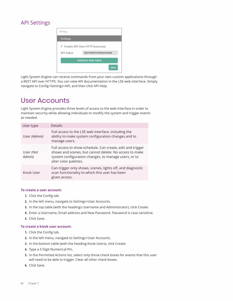
68 Chapter 7
API Settings
Light System Engine can receive commands from your own custom applications through a REST API over HTTPS. You can view API documentation in the LSE web interface. Simply navigate to Config>Settings>API, and then click API Help.
User AccountsLight System Engine provides three levels of access to the web interface in order to maintain security while allowing individuals to modify the system and trigger events as needed.
User type Details
User (Admin)Full access to the LSE web interface, including the ability to make system configuration changes and to manage users.
User (Not Admin)
Full access to show schedule. Can create, edit and trigger shows and scenes, but cannot delete. No access to make system configuration changes, to manage users, or to alter color palettes.
Kiosk UserCan trigger only shows, scenes, lights off, and diagnostic scan functionality to which this user has been given access.
To create a user account:
1. Click the Config tab.
2. In the left menu, navigate to Settings>User Accounts.
3. In the top table (with the headings Username and Administrator), click Create.
4. Enter a Username, Email address and New Password. Password is case-sensitive.
5. Click Save.
To create a kiosk user account:
1. Click the Config tab.
2. In the left menu, navigate to Settings>User Accounts.
3. In the bottom table (with the heading Kiosk Users), click Create.
4. Type a 5 Digit Numerical Pin.
5. In the Permitted Actions list, select only those check boxes for events that this user will need to be able to trigger. Clear all other check boxes.
6. Click Save.

Light System Manager User Guide 69
To modify an existing user:
1. Click the Config tab.
2. In the left menu, navigate to Settings>User Accounts.
3. Locate the user or kiosk user, and click Edit.
4. Update the settings as required, and then click Save.
To delete a user:
1. Click the Config tab.
2. In the left menu, navigate to Settings>User Accounts.
3. Locate the user or kiosk user, and click Delete.
E To restrict access to Light System Engine, change the default user name and password.

70 Chapter 7
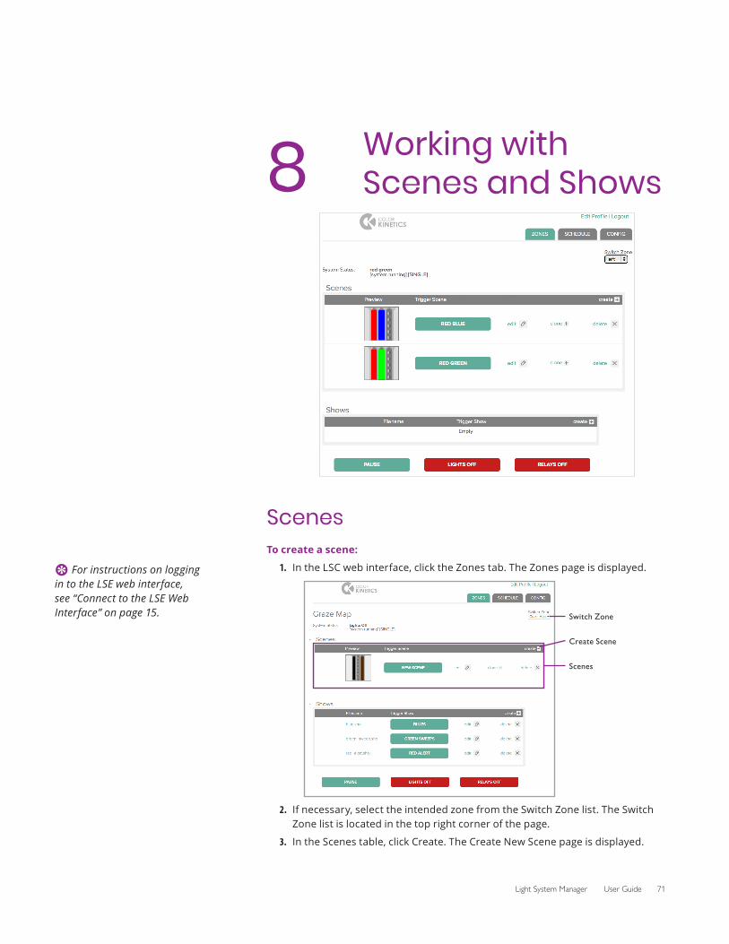
Light System Manager User Guide 71
8 Working with Scenes and Shows
ScenesTo create a scene:
1. In the LSC web interface, click the Zones tab. The Zones page is displayed.
2.
Switch Zone
Scenes
Create Scene
If necessary, select the intended zone from the Switch Zone list. The Switch Zone list is located in the top right corner of the page.
3. In the Scenes table, click Create. The Create New Scene page is displayed.
E For instructions on logging in to the LSE web interface, see “Connect to the LSE Web Interface” on page 15.
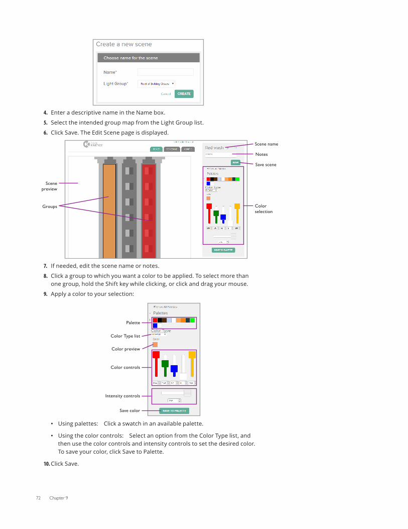
72 Chapter 9
4. Enter a descriptive name in the Name box.
5. Select the intended group map from the Light Group list.
6. Click Save. The Edit Scene page is displayed.
7.
Scene preview
Groups
Notes
Save scene
Scene name
Color selection
If needed, edit the scene name or notes.
8. Click a group to which you want a color to be applied. To select more than one group, hold the Shift key while clicking, or click and drag your mouse.
9. Apply a color to your selection:
Color Type list
Palette
Color preview
Color controls
Intensity controls
Save color
• Using palettes: Click a swatch in an available palette.
• Using the color controls: Select an option from the Color Type list, and then use the color controls and intensity controls to set the desired color. To save your color, click Save to Palette.
10. Click Save.
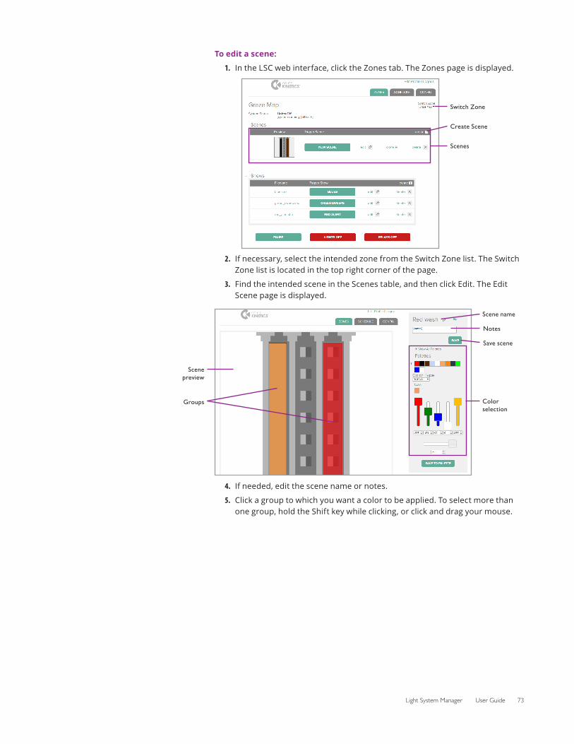
Light System Manager User Guide 73
To edit a scene:
1. In the LSC web interface, click the Zones tab. The Zones page is displayed.
2.
Switch Zone
Scenes
Create Scene
If necessary, select the intended zone from the Switch Zone list. The Switch Zone list is located in the top right corner of the page.
3. Find the intended scene in the Scenes table, and then click Edit. The Edit Scene page is displayed.
Scene preview
Groups
Notes
Save scene
Scene name
Color selection
4. If needed, edit the scene name or notes.
5. Click a group to which you want a color to be applied. To select more than one group, hold the Shift key while clicking, or click and drag your mouse.
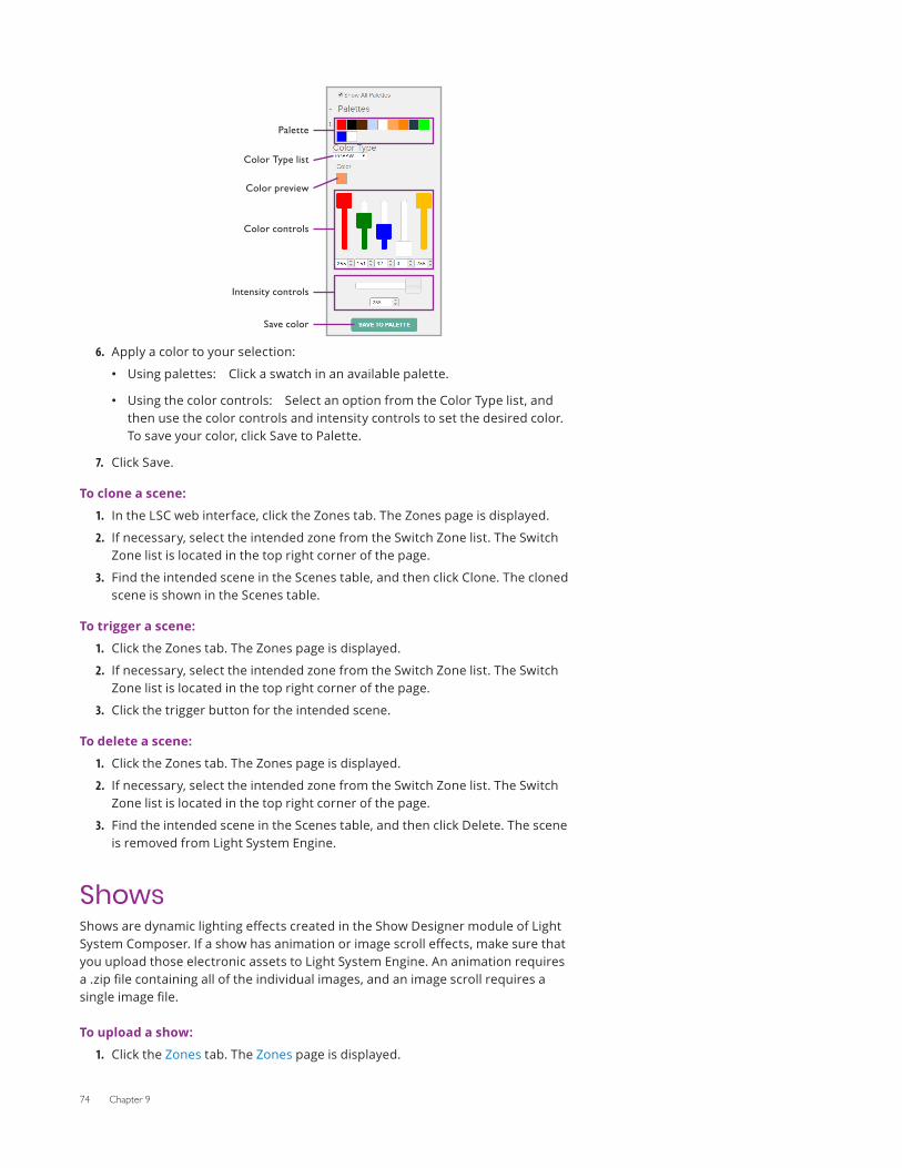
74 Chapter 9
6.
Color Type list
Palette
Color preview
Color controls
Intensity controls
Save color
Apply a color to your selection:
• Using palettes: Click a swatch in an available palette.
• Using the color controls: Select an option from the Color Type list, and then use the color controls and intensity controls to set the desired color. To save your color, click Save to Palette.
7. Click Save.
To clone a scene:
1. In the LSC web interface, click the Zones tab. The Zones page is displayed.
2. If necessary, select the intended zone from the Switch Zone list. The Switch Zone list is located in the top right corner of the page.
3. Find the intended scene in the Scenes table, and then click Clone. The cloned scene is shown in the Scenes table.
To trigger a scene:
1. Click the Zones tab. The Zones page is displayed.
2. If necessary, select the intended zone from the Switch Zone list. The Switch Zone list is located in the top right corner of the page.
3. Click the trigger button for the intended scene.
To delete a scene:
1. Click the Zones tab. The Zones page is displayed.
2. If necessary, select the intended zone from the Switch Zone list. The Switch Zone list is located in the top right corner of the page.
3. Find the intended scene in the Scenes table, and then click Delete. The scene is removed from Light System Engine.
ShowsShows are dynamic lighting effects created in the Show Designer module of Light System Composer. If a show has animation or image scroll effects, make sure that you upload those electronic assets to Light System Engine. An animation requires a .zip file containing all of the individual images, and an image scroll requires a single image file.
To upload a show:
1. Click the Zones tab. The Zones page is displayed.
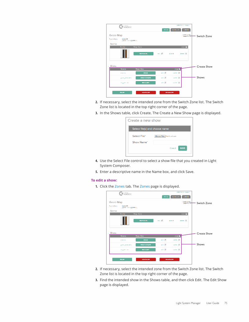
Light System Manager User Guide 75
2.
Switch Zone
Shows
Create Show
If necessary, select the intended zone from the Switch Zone list. The Switch Zone list is located in the top right corner of the page.
3. In the Shows table, click Create. The Create a New Show page is displayed.
4. Use the Select File control to select a show file that you created in Light System Composer.
5. Enter a descriptive name in the Name box, and click Save.
To edit a show:
1. Click the Zones tab. The Zones page is displayed.
2.
Switch Zone
Shows
Create Show
If necessary, select the intended zone from the Switch Zone list. The Switch Zone list is located in the top right corner of the page.
3. Find the intended show in the Shows table, and then click Edit. The Edit Show page is displayed.
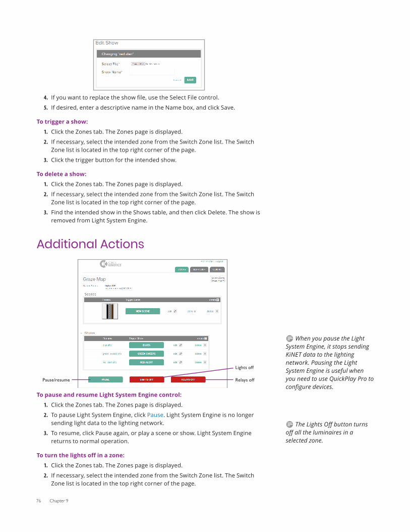
76 Chapter 9
4. If you want to replace the show file, use the Select File control.
5. If desired, enter a descriptive name in the Name box, and click Save.
To trigger a show:
1. Click the Zones tab. The Zones page is displayed.
2. If necessary, select the intended zone from the Switch Zone list. The Switch Zone list is located in the top right corner of the page.
3. Click the trigger button for the intended show.
To delete a show:
1. Click the Zones tab. The Zones page is displayed.
2. If necessary, select the intended zone from the Switch Zone list. The Switch Zone list is located in the top right corner of the page.
3. Find the intended show in the Shows table, and then click Delete. The show is removed from Light System Engine.
Additional Actions
To
Pause/resume
Lights off
Relays off
pause and resume Light System Engine control:
1. Click the Zones tab. The Zones page is displayed.
2. To pause Light System Engine, click Pause. Light System Engine is no longer sending light data to the lighting network.
3. To resume, click Pause again, or play a scene or show. Light System Engine returns to normal operation.
To turn the lights off in a zone:
1. Click the Zones tab. The Zones page is displayed.
2. If necessary, select the intended zone from the Switch Zone list. The Switch Zone list is located in the top right corner of the page.
D When you pause the Light System Engine, it stops sending KiNET data to the lighting network. Pausing the Light System Engine is useful when you need to use QuickPlay Pro to configure devices.
D The Lights Off button turns off all the luminaires in a selected zone.
Light System Manager User Guide 77
3. Click Lights Off.
4. Play a scene or show to resume normal operation.
To turn off the power/data supply relays in a zone:
1. Click the Zones tab. The Zones page is displayed.
2. If necessary, select the intended zone from the Switch Zone list. The Switch Zone list is located in the top right corner of the page.
3. Click Relays Off.
4. Play a scene or show to close relays and resume normal operation.
D Opening the relays on a power/data supply removes power from any attached luminaires, reducing energy consumption.

78 Chapter 9
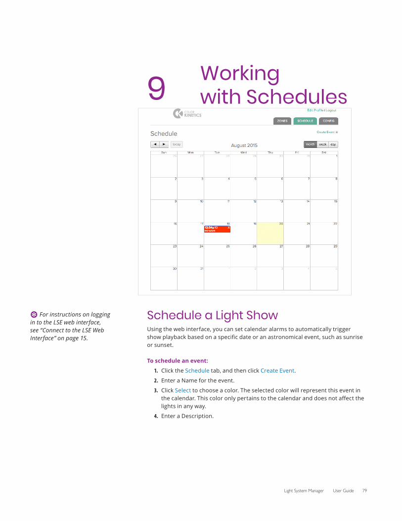
Light System Manager User Guide 79
9 Working with Schedules
Schedule a Light ShowUsing the web interface, you can set calendar alarms to automatically trigger show playback based on a specific date or an astronomical event, such as sunrise or sunset.
To schedule an event:
1. Click the Schedule tab, and then click Create Event.
2. Enter a Name for the event.
3. Click Select to choose a color. The selected color will represent this event in the calendar. This color only pertains to the calendar and does not affect the lights in any way.
4. Enter a Description.
E For instructions on logging in to the LSE web interface, see “Connect to the LSE Web Interface” on page 15.
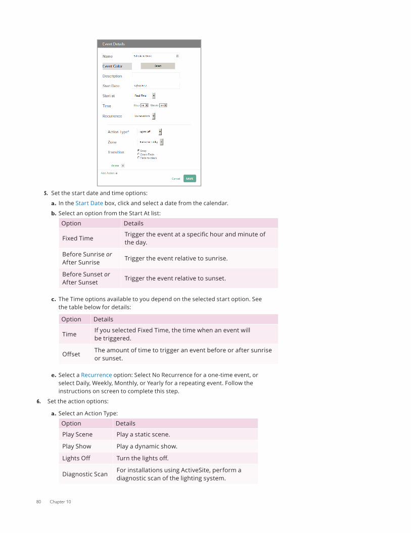
80 Chapter 10
5. Set the start date and time options:
a. In the Start Date box, click and select a date from the calendar.
b. Select an option from the Start At list:
Option Details
Fixed TimeTrigger the event at a specific hour and minute of the day.
Before Sunrise or After Sunrise
Trigger the event relative to sunrise.
Before Sunset or After Sunset
Trigger the event relative to sunset.
c. The Time options available to you depend on the selected start option. See the table below for details:
Option Details
TimeIf you selected Fixed Time, the time when an event will be triggered.
OffsetThe amount of time to trigger an event before or after sunrise or sunset.
e. Select a Recurrence option: Select No Recurrence for a one-time event, or select Daily, Weekly, Monthly, or Yearly for a repeating event. Follow the instructions on screen to complete this step.
6. Set the action options:
a. Select an Action Type:
Option Details
Play Scene Play a static scene.
Play Show Play a dynamic show.
Lights Off Turn the lights off.
Diagnostic ScanFor installations using ActiveSite, perform a diagnostic scan of the lighting system.
Light System Manager User Guide 81
Option Details
Relays OffOpen relays to a specific group so that the LED nodes in that group are not receiving power. This is a lower power state than Lights Off.
b. The action options available to you will change depending on the selected Action Type. See the table below for details:
Option Details
Zone Zone to which the event applies.
Scene Scenes available for playback in the selected zone.
ShowLight show available for playback in the selected zone.
GroupGroup whose relays will be opened. Available only if the Action Type option is set to Relays Off.
Transition
Snap Zero-second transition (no fade).
Cross-Fade Fade to a scene or show. Speed of the transition can be set using the Transition Time option.
Fade-to-Black Fade to black, then fade to a scene or show. Speed of the transition can be set using the Transition Time option.
Transition Time
Duration of the transition in hours, minutes and seconds.
7. If desired, add another action.
8. Click Save.

82 Chapter 10
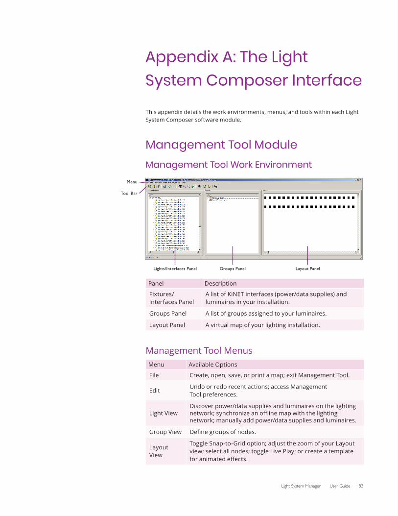
Light System Manager User Guide 83
Appendix A: The Light System Composer Interface
This appendix details the work environments, menus, and tools within each Light System Composer software module.
Management Tool ModuleManagement Tool Work Environment
Menu
Tool Bar
Lights/Interfaces Panel Groups Panel Layout Panel
Panel Description
Fixtures/Interfaces Panel
A list of KiNET interfaces (power/data supplies) and luminaires in your installation.
Groups Panel A list of groups assigned to your luminaires.
Layout Panel A virtual map of your lighting installation.
Management Tool MenusMenu Available Options
File Create, open, save, or print a map; exit Management Tool.
EditUndo or redo recent actions; access Management Tool preferences.
Light ViewDiscover power/data supplies and luminaires on the lighting network; synchronize an offline map with the lighting network; manually add power/data supplies and luminaires.
Group View Define groups of nodes.
Layout View
Toggle Snap-to-Grid option; adjust the zoom of your Layout view; select all nodes; toggle Live Play; or create a template for animated effects.
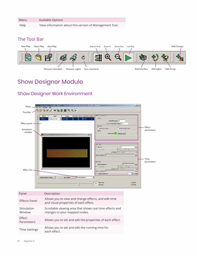
84 Appendix A
Menu Available Options
Help View information about this version of Management Tool.
The Tool BarAdd Groups
Discover Interfaces
New Map Open Map Save Map Snap to Grid Zoom In Zoom Out Live Play
Add Interface Add Lights Add StringDiscover Lights Sync Interfaces
Show Designer Module
Show Designer Work Environment
Effect parameters
Time parameters
Menu
Tool Bar
Effect panel
Simulation window
Effect list
Panel Description
Effects PanelAllows you to view and change effects, and edit time and visual properties of each effect.
Simulation Window
Scrollable viewing area that shows real time effects and changes to your mapped nodes.
Effect Parameters
Allows you to set and edit the properties of each effect.
Time SettingsAllows you to set and edit the running time for each effect.
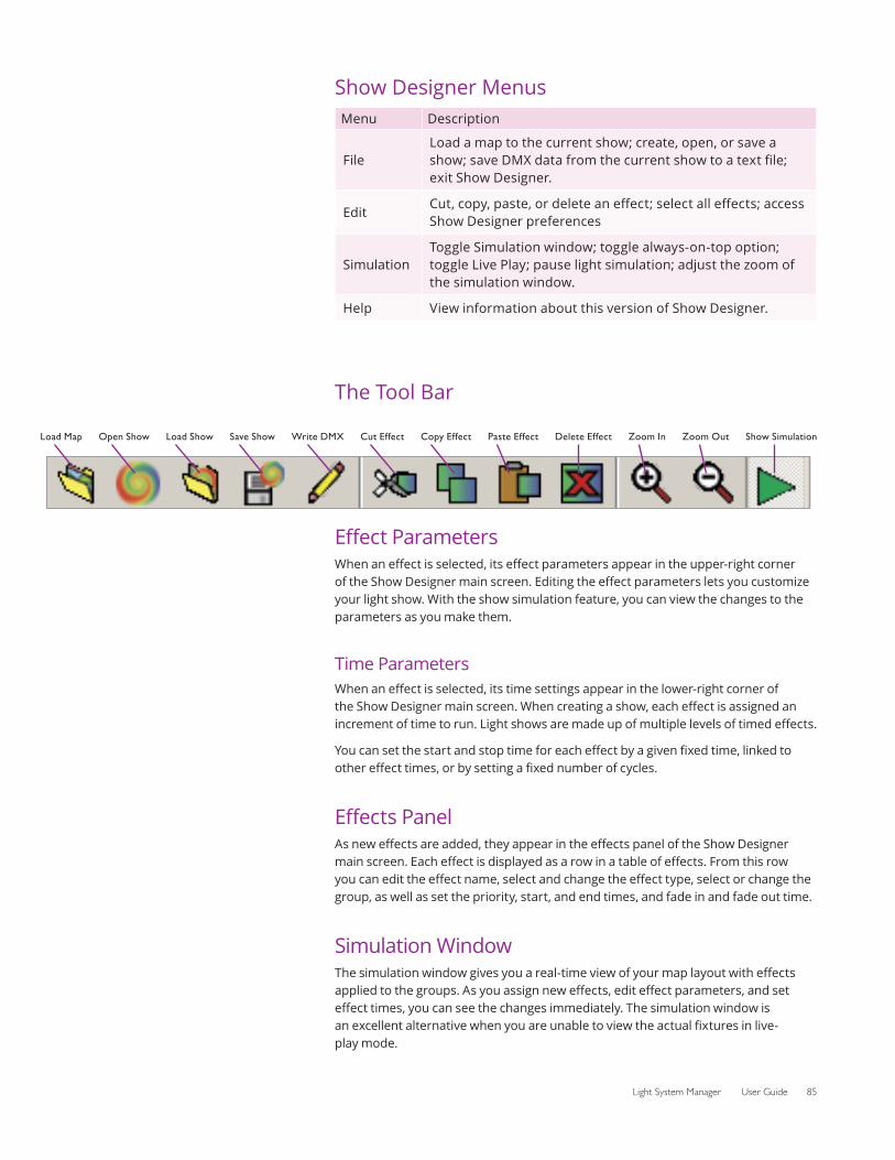
Light System Manager User Guide 85
Show Designer MenusMenu Description
FileLoad a map to the current show; create, open, or save a show; save DMX data from the current show to a text file; exit Show Designer.
EditCut, copy, paste, or delete an effect; select all effects; access Show Designer preferences
SimulationToggle Simulation window; toggle always-on-top option; toggle Live Play; pause light simulation; adjust the zoom of the simulation window.
Help View information about this version of Show Designer.
The Tool Bar
Load Map Open Show Load Show Save Show Write DMX Cut Effect Copy Effect Paste Effect Delete Effect Zoom In Zoom Out Show Simulation
Effect ParametersWhen an effect is selected, its effect parameters appear in the upper-right corner of the Show Designer main screen. Editing the effect parameters lets you customize your light show. With the show simulation feature, you can view the changes to the parameters as you make them.
Time ParametersWhen an effect is selected, its time settings appear in the lower-right corner of the Show Designer main screen. When creating a show, each effect is assigned an increment of time to run. Light shows are made up of multiple levels of timed effects.
You can set the start and stop time for each effect by a given fixed time, linked to other effect times, or by setting a fixed number of cycles.
Effects PanelAs new effects are added, they appear in the effects panel of the Show Designer main screen. Each effect is displayed as a row in a table of effects. From this row you can edit the effect name, select and change the effect type, select or change the group, as well as set the priority, start, and end times, and fade in and fade out time.
Simulation WindowThe simulation window gives you a real-time view of your map layout with effects applied to the groups. As you assign new effects, edit effect parameters, and set effect times, you can see the changes immediately. The simulation window is an excellent alternative when you are unable to view the actual fixtures in live-play mode.

86 Appendix A
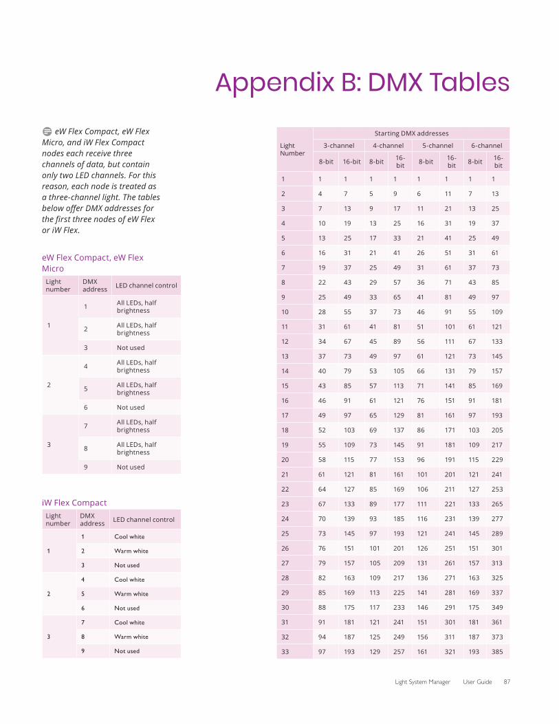
Light System Manager User Guide 87
Appendix B: DMX Tables
Light Number
Starting DMX addresses
3-channel 4-channel 5-channel 6-channel
8-bit 16-bit 8-bit 16-bit 8-bit 16-
bit 8-bit 16-bit
1 1 1 1 1 1 1 1 1
2 4 7 5 9 6 11 7 13
3 7 13 9 17 11 21 13 25
4 10 19 13 25 16 31 19 37
5 13 25 17 33 21 41 25 49
6 16 31 21 41 26 51 31 61
7 19 37 25 49 31 61 37 73
8 22 43 29 57 36 71 43 85
9 25 49 33 65 41 81 49 97
10 28 55 37 73 46 91 55 109
11 31 61 41 81 51 101 61 121
12 34 67 45 89 56 111 67 133
13 37 73 49 97 61 121 73 145
14 40 79 53 105 66 131 79 157
15 43 85 57 113 71 141 85 169
16 46 91 61 121 76 151 91 181
17 49 97 65 129 81 161 97 193
18 52 103 69 137 86 171 103 205
19 55 109 73 145 91 181 109 217
20 58 115 77 153 96 191 115 229
21 61 121 81 161 101 201 121 241
22 64 127 85 169 106 211 127 253
23 67 133 89 177 111 221 133 265
24 70 139 93 185 116 231 139 277
25 73 145 97 193 121 241 145 289
26 76 151 101 201 126 251 151 301
27 79 157 105 209 131 261 157 313
28 82 163 109 217 136 271 163 325
29 85 169 113 225 141 281 169 337
30 88 175 117 233 146 291 175 349
31 91 181 121 241 151 301 181 361
32 94 187 125 249 156 311 187 373
33 97 193 129 257 161 321 193 385
D eW Flex Compact, eW Flex Micro, and iW Flex Compact nodes each receive three channels of data, but contain only two LED channels. For this reason, each node is treated as a three-channel light. The tables below offer DMX addresses for the first three nodes of eW Flex or iW Flex.
eW Flex Compact, eW Flex Micro
Light number
DMX address LED channel control
1
1 All LEDs, half brightness
2 All LEDs, half brightness
3 Not used
2
4 All LEDs, half brightness
5 All LEDs, half brightness
6 Not used
3
7 All LEDs, half brightness
8 All LEDs, half brightness
9 Not used
iW Flex Compact Light number
DMX address LED channel control
1
1 Cool white
2 Warm white
3 Not used
2
4 Cool white
5 Warm white
6 Not used
3
7 Cool white
8 Warm white
9 Not used
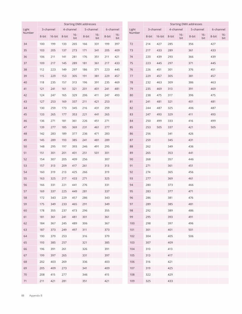
88 Appendix B
Light Number
Starting DMX addresses
3-channel 4-channel 5-channel 6-channel
8-bit 16-bit 8-bit 16-bit 8-bit 16-
bit 8-bit 16-bit
34 100 199 133 265 166 331 199 397
35 103 205 137 273 171 341 205 409
36 106 211 141 281 176 351 211 421
37 109 217 145 289 181 361 217 433
38 112 223 149 297 186 371 223 445
39 115 229 153 305 191 381 229 457
40 118 235 157 313 196 391 235 469
41 121 241 161 321 201 401 241 481
42 124 247 165 329 206 411 247 493
43 127 253 169 337 211 421 253
44 130 259 173 345 216 431 259
45 133 265 177 353 221 441 265
46 136 271 181 361 226 451 271
47 139 277 185 369 231 461 277
48 142 283 189 377 236 471 283
49 145 289 193 385 241 481 289
50 148 295 197 393 246 491 295
51 151 301 201 401 251 501 301
52 154 307 205 409 256 307
53 157 313 209 417 261 313
54 160 319 213 425 266 319
55 163 325 217 433 271 325
56 166 331 221 441 276 331
57 169 337 225 449 281 337
58 172 343 229 457 286 343
59 175 349 233 465 291 349
60 178 355 237 473 296 355
61 181 361 241 481 301 361
62 184 367 245 489 306 367
63 187 373 249 497 311 373
64 190 379 253 316 379
65 193 385 257 321 385
66 196 391 261 326 391
67 199 397 265 331 397
68 202 403 269 336 403
69 205 409 273 341 409
70 208 415 277 346 415
71 211 421 281 351 421
Light Number
Starting DMX addresses
3-channel 4-channel 5-channel 6-channel
8-bit 16-bit 8-bit 16-bit 8-bit 16-
bit 8-bit 16-bit
72 214 427 285 356 427
73 217 433 289 361 433
74 220 439 293 366 439
75 223 445 297 371 445
76 226 451 301 376 451
77 229 457 305 381 457
78 232 463 309 386 463
79 235 469 313 391 469
80 238 475 317 396 475
81 241 481 321 401 481
82 244 487 325 406 487
83 247 493 329 411 493
84 250 499 333 416 499
85 253 505 337 421 505
86 256 341 426
87 259 345 431
88 262 349 436
89 265 353 441
90 268 357 446
91 271 361 451
92 274 365 456
93 277 369 461
94 280 373 466
95 283 377 471
96 286 381 476
97 289 385 481
98 292 389 486
99 295 393 491
100 298 397 496
101 301 401 501
102 304 405 506
103 307 409
104 310 413
105 313 417
106 316 421
107 319 425
108 322 429
109 325 433
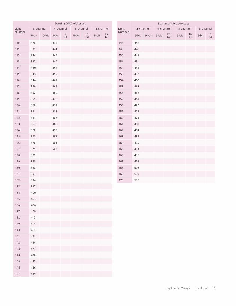
Light System Manager User Guide 89
Light Number
Starting DMX addresses
3-channel 4-channel 5-channel 6-channel
8-bit 16-bit 8-bit 16-bit 8-bit 16-
bit 8-bit 16-bit
110 328 437
111 331 441
112 334 445
113 337 449
114 340 453
115 343 457
116 346 461
117 349 465
118 352 469
119 355 473
120 358 477
121 361 481
122 364 485
123 367 489
124 370 493
125 373 497
126 376 501
127 379 505
128 382
129 385
130 388
131 391
132 394
133 397
134 400
135 403
136 406
137 409
138 412
139 415
140 418
141 421
142 424
143 427
144 430
145 433
146 436
147 439
Light Number
Starting DMX addresses
3-channel 4-channel 5-channel 6-channel
8-bit 16-bit 8-bit 16-bit 8-bit 16-
bit 8-bit 16-bit
148 442
149 445
150 448
151 451
152 454
153 457
154 460
155 463
156 466
157 469
158 472
159 475
160 478
161 481
162 484
163 487
164 490
165 493
166 496
167 499
168 502
169 505
170 508

90 Appendix B
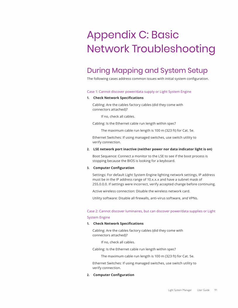
Light System Manager User Guide 91
Appendix C: Basic Network Troubleshooting
During Mapping and System SetupThe following cases address common issues with initial system configuration.
Case 1: Cannot discover power/data supply or Light System Engine
1. Check Network Specifications
Cabling: Are the cables factory cables (did they come with connectors attached)?
If no, check all cables.
Cabling: Is the Ethernet cable run length within spec?
The maximum cable run length is 100 m (323 ft) for Cat. 5e.
Ethernet Switches: If using managed switches, use switch utility to verify connection.
2. LSE network port inactive (neither power nor data indicator light is on)
Boot Sequence: Connect a monitor to the LSE to see if the boot process is stopping because the BIOS is looking for a keyboard.
3. Computer Configuration
Settings: For default Light System Engine lighting network settings, IP address must be in the IP address range of 10.x.x.x and have a subnet mask of 255.0.0.0. If settings were incorrect, verify accepted change before continuing.
Active wireless connection: Disable the wireless network card.
Utility software: Disable all firewalls, anti-virus software, and VPNs.
Case 2: Cannot discover luminaires, but can discover power/data supplies or Light
System Engine
1. Check Network Specifications
Cabling: Are the cables factory cables (did they come with connectors attached)?
If no, check all cables.
Cabling: Is the Ethernet cable run length within spec?
The maximum cable run length is 100 m (323 ft) for Cat. 5e.
Ethernet Switches: If using managed switches, use switch utility to verify connection.
2. Computer Configuration

92 Appendix C
Settings: For default Light System Engine lighting network settings, IP address must be in the IP address range of 10.x.x.x and have a subnet mask of 255.0.0.0. If settings were incorrect, verify accepted change before continuing.
Active wireless connection: Disable the wireless network card.
Utility software: Disable all firewalls, anti-virus software, and VPNs.
Case 3: Cannot connect to Light System Engine, but all other network components
are accessible
1. Test Network Cables/Switches
Cables: If cables/switches are suspected, use a crossover cable to directly connect the computer to Light System Engine and verify connectivity.
2. Ping Light System Engine
For default Light System Engine lighting network settings, ping 10.1.3.100. If “request timed out”, check the Light System Engine network activity light.
3. Reboot
Make sure Light System Engine boots completely.
If an incomplete boot is suspected, attach a monitor; if a keyboard or mouse is requested, connect a keyboard or mouse, accordingly.
Post-MappingThe following cases address issues where the the lighting installation has been functional for a period of time.
Case 1: Cannot discover power/data supplies or Light System Engine
1. Computer Configuration
Settings: For default Light System Engine lighting network settings, IP address must be in the IP address range of 10.x.x.x and have a subnet mask of 255.0.0.0.
Active wireless connection: Disable the wireless network card.
Utility software: Turn off all firewalls, anti-virus software, and VPNs.
2. Network
Cabling: Were the cables factory cables (did they come with connectors attached)?
If no, check all cables.
Ethernet Switches: Switches can fail; use a switch tester to verify that the switches are functional
Case 2: Cannot discover luminaires, but can discover power/data supplies or Light
System Engine
1. Computer Configuration

Light System Manager User Guide 93
Settings: For default Light System Engine lighting network settings, IP address must be in the IP address range of 10.x.x.x and have a subnet mask of 255.0.0.0.
Active wireless connection: Disable the wireless network card.
Utility software: Turn off all firewalls, anti-virus software, and VPNs
2. Network
Cabling: Were the cables factory cables (did they come with connectors attached)?
If no, check all cables.
Ethernet Switches: Switches can fail; use a switch tester to verify that the switches are functional
Case 3: Cannot connect to Light System Engine, but all other network
components are accessible
1. Test Network Cables/Switches
Cables: If cables/switches are suspected, use a crossover cable to directly connect the computer to Light System Engine and verify connectivity.
2. Ping LSE
Ping 10.1.3.100. If “request timed out”, check the Light System Engine network activity indicator light.
3. Reboot
Make sure Light System Engine boots completely.
If an incomplete boot is suspected, attach a monitor; if a keyboard or mouse is requested, connect a keyboard or mouse, accordingly.
Case 4: Some luminaires do not work
1. Network
Check connections to all power/data supplies
Rediscover all lighting components using Management Tool. If some components don’t register, begin the Network troubleshooting processes listed in the previous cases.
Technical Support ContactsContact Color Kinetics technical support for assistance with hardware or software questions:
Phone
888.Full.RGB (888.385.5742), press option number 3 (toll free US, Canada and Mexico)
617.423.9999, press option number 3 (toll worldwide)
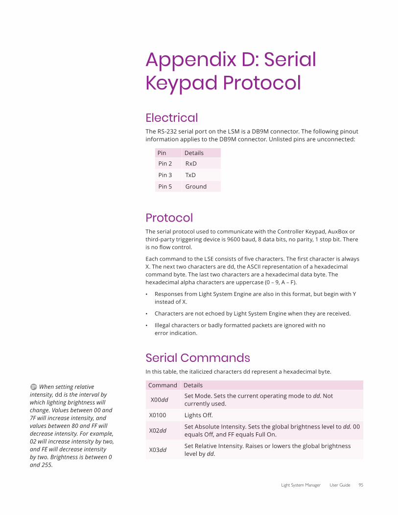
Light System Manager User Guide 95
Appendix D: Serial Keypad ProtocolElectricalThe RS-232 serial port on the LSM is a DB9M connector. The following pinout information applies to the DB9M connector. Unlisted pins are unconnected:
Pin Details
Pin 2 RxD
Pin 3 TxD
Pin 5 Ground
ProtocolThe serial protocol used to communicate with the Controller Keypad, AuxBox or third-party triggering device is 9600 baud, 8 data bits, no parity, 1 stop bit. There is no flow control.
Each command to the LSE consists of five characters. The first character is always X. The next two characters are dd, the ASCII representation of a hexadecimal command byte. The last two characters are a hexadecimal data byte. The hexadecimal alpha characters are uppercase (0 – 9, A – F).
• Responses from Light System Engine are also in this format, but begin with Y instead of X.
• Characters are not echoed by Light System Engine when they are received.
• Illegal characters or badly formatted packets are ignored with no error indication.
Serial CommandsIn this table, the italicized characters dd represent a hexadecimal byte.
Command Details
X00ddSet Mode. Sets the current operating mode to dd. Not currently used.
X0100 Lights Off.
X02ddSet Absolute Intensity. Sets the global brightness level to dd. 00 equals Off, and FF equals Full On.
X03ddSet Relative Intensity. Raises or lowers the global brightness level by dd.
D When setting relative intensity, dd is the interval by which lighting brightness will change. Values between 00 and 7F will increase intensity, and values between 80 and FF will decrease intensity. For example, 02 will increase intensity by two, and FE will decrease intensity by two. Brightness is between 0 and 255.
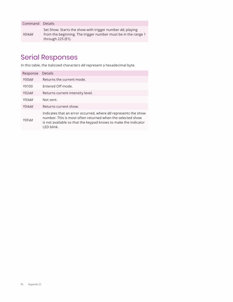
96 Appendix D
Command Details
X04ddSet Show. Starts the show with trigger number dd, playing from the beginning. The trigger number must be in the range 1 through 225 (E1).
Serial ResponsesIn this table, the italicized characters dd represent a hexadecimal byte.
Response Details
Y00dd Returns the current mode.
Y0100 Entered Off mode.
Y02dd Returns current intensity level.
Y03dd Not sent.
Y04dd Returns current show.
Y0Fdd
Indicates that an error occurred, where dd represents the show number. This is most often returned when the selected show is not available so that the keypad knows to make the indicator LED blink.
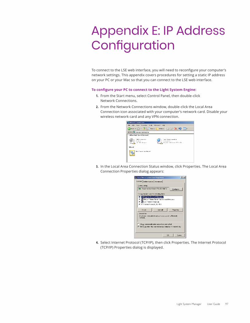
Light System Manager User Guide 97
To connect to the LSE web interface, you will need to reconfigure your computer’s network settings. This appendix covers procedures for setting a static IP address on your PC or your Mac so that you can connect to the LSE web interface.
To configure your PC to connect to the Light System Engine:
1. From the Start menu, select Control Panel, then double-click Network Connections.
2. From the Network Connections window, double-click the Local Area Connection icon associated with your computer’s network card. Disable your wireless network card and any VPN connection.
3. In the Local Area Connection Status window, click Properties. The Local Area Connection Properties dialog appears:
4. Select Internet Protocol (TCP/IP), then click Properties. The Internet Protocol (TCP/IP) Properties dialog is displayed.
Appendix E: IP Address Configuration
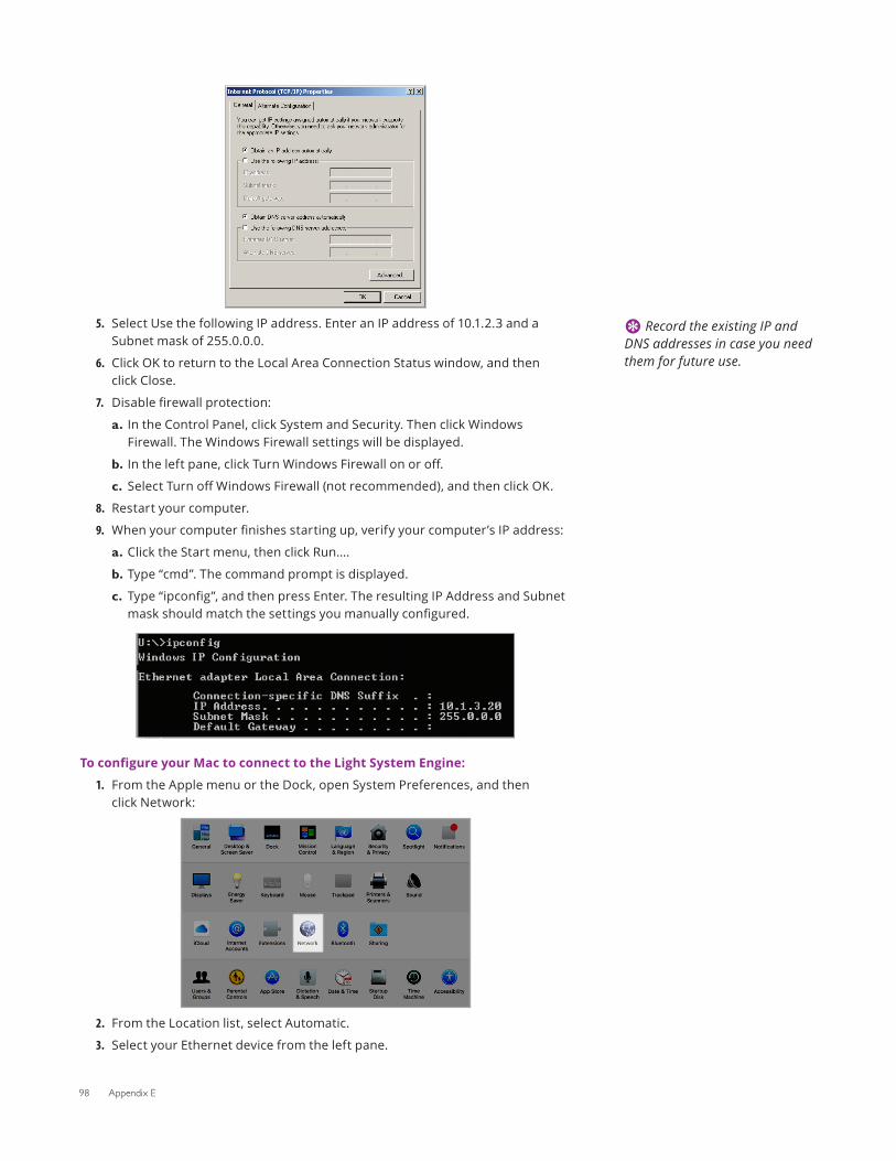
98 Appendix E
5. Select Use the following IP address. Enter an IP address of 10.1.2.3 and a Subnet mask of 255.0.0.0.
6. Click OK to return to the Local Area Connection Status window, and then click Close.
7. Disable firewall protection:
a. In the Control Panel, click System and Security. Then click Windows Firewall. The Windows Firewall settings will be displayed.
b. In the left pane, click Turn Windows Firewall on or off.
c. Select Turn off Windows Firewall (not recommended), and then click OK.
8. Restart your computer.
9. When your computer finishes starting up, verify your computer’s IP address:
a. Click the Start menu, then click Run….
b. Type “cmd”. The command prompt is displayed.
c. Type “ipconfig”, and then press Enter. The resulting IP Address and Subnet mask should match the settings you manually configured.
To configure your Mac to connect to the Light System Engine:
1. From the Apple menu or the Dock, open System Preferences, and then click Network:
2. From the Location list, select Automatic.
3. Select your Ethernet device from the left pane.
E Record the existing IP and DNS addresses in case you need them for future use.
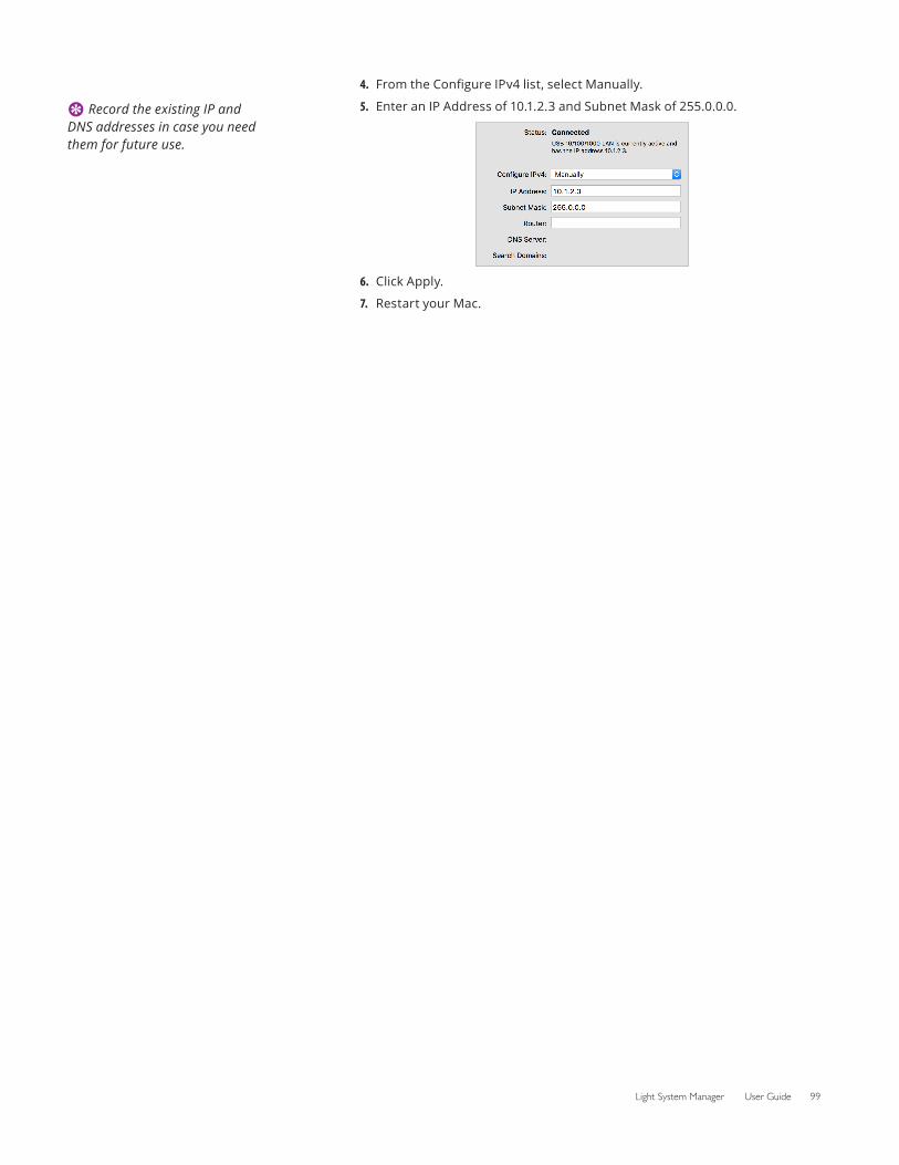
Light System Manager User Guide 99
4. From the Configure IPv4 list, select Manually.
5. Enter an IP Address of 10.1.2.3 and Subnet Mask of 255.0.0.0.
6. Click Apply.
7. Restart your Mac.
E Record the existing IP and DNS addresses in case you need them for future use.

100 Appendix E
Light System Manager User Guide 101
Appendix F: Additional Configuration
Software
IntroductionConfiguration tools help you rename and address luminaires, power/data supplies, and Antumbra Ethernet Keypads from Color Kinetics.
QuickPlay Pro addressing and configuration software is available for download online at www.colorkinetics.com/support/userguides/.
QuickPlay Pro
OverviewAs part of the configuration process, all power/data supplies and luminaires must be configured with unique device names, IP addresses, and/or light numbers or DMX addresses. Unique naming and addressing allows Light System Engine to differentiate between devices in a network. QuickPlay Pro performs addressing and naming functions for all possible types of hardware used in an Light System Manager installation requiring an external addressing tool (some fixtures and interfaces have built-in addressing tools).
There are three methods for addressing fixtures from Color Kinetics, two of which require QuickPlay Pro:
• Serial addressing applies to most Chromacore fixtures (Chromacore fixtures receive light numbers based on serial numbers) and all ColorReach Powercore fixtures.
• Base light number configuration applies to all Chromasic fixtures and Accent family fixtures.
• Onboard addressing applies to fixtures and power/data supplies that have onboard hardware addressing controls. QuickPlay Pro is not used to address fixtures or power/data supplies that have onboard addressing features.
Chromacore luminaires are programmed with light numbers via the Fixture Configuration tool in QuickPlay Pro. To configure a Chromacore luminaire or node, you enter the serial number, specify a light number, and then click Program. The unique serial numbers for Chromacore luminaires can be found on barcode labels typically located on the back of each unit.

102 Appendix F
If your installation uses Chromasic luminaires, the power/data supplies controlling those luminaires must be configured. You configure power/data supplies using the PDS Configuration Tool in QuickPlay Pro.
Launch QuickPlay ProOn Windows: Select Start>All Programs>Color Kinetics>QuickPlay Pro
On macOS: Click the QuickPlay Pro icon in the Dock
Light System Manager User Guide 103
Appendix G: TutorialsCreate a Placeholder Map
OverviewWhen connected to a lighting network, Management Tool automatically discovers all Ethernet lighting components. There are two stages of the automatic discovery process:
1. Discover KiNET interfaces (power/data supplies and Ethernet Data Enablers)
2. Discover fixtures
However, in this tutorial, we are going to create a placeholder map. Placeholder maps are useful when you are offline, not connected to the lighting network, but know the location of each KiNET interface and fixture. You can create a placeholder map and then associate the map with an actual installation at a later time.
Steps1. Open the Management Tool module.
2. Click Add Interface and leave the default interface type (KiNET) selected.
3. Click OK.
4. Enter a name for the interface, for example “PDS-60ca 01 West Hallway”
5. Enter an IP address in the 10.1.x.x range.
6. Select Add RGB Lights.
7. Enter a fixture quantity of 10.
8. Select the Horizontally radio button to specify layout orientation.
9. Select the existing interface created in steps four and five.
10. Enter a base DMX address as the starting DMX address for the first fixture.
11. Select a port number on the interface, for example 1 or 2.
12. Choose a base light name. For example West Hallway Cove. Management Tool displays each fixture on-screen according to its light name plus its light number, for example “West Hallway Cove 27”.
13. Click OK.
14. Select all of the fixtures, then select Add Group.
15. Enter a group name, then click OK.
16. Select File>Save Map to save your work.
Later, when you are onsite at an installation for example, you can associate the map with the actual interfaces fixtures in your installation. See page 38 for details on associating placeholder maps.

Color Kineticswww.colorkinetics.com
© 2019 Signify Holding. All rights reserved. Specifications are subject to change without notice. No representation or warranty as to the accuracy or completeness of the information included herein is given and any liability for any action in reliance thereon is disclaimed. All other trademarks are owned by Signify Holding or their respective owners. Throughout this brochure, installation photos of Color Kinetics lighting products are featured—and in minor instances, products from other companies may be included in those photos.
PUB-000232-01 R17 11-18
© 2018 Signify Holding. All rights reserved. Specifications are subject to change without notice. No representation or warranty as to the accuracy or completeness of the information included herein is given and any liability for any action in reliance thereon is disclaimed. All trademarks are owned by Signify Holding or their respective owners. www.colorkinetics.com
PUB-000232-01 (R07) November 2018