LIGHT COMMERCIAL PACKAGED GAS UNIT - · PDF fileLIGHT COMMERCIAL PACKAGED GAS UNIT ......
52
© 2013 - 2017 5151 San Felipe St., Suite 500, Houston, TX 77056 www.daikinac.com ATTENTION INSTALLING PERSONNEL: Prior to installation, thoroughly familiarize yourself with this Installation Manual. Observe all safety warnings. Dur- ing installation or repair, caution is to be observed. It is your responsibility to install the product safely and to educate the customer on its safe use. RECOGNIZE THIS SYMBOL AS A SAFETY PRECAUTION. These installation instructions cover the outdoor installation of single package heating and cooling units. See the Specification Sheet applicable to your model for information regarding accessories. *NOTE: Please contact your distributor or our website for the applicable Specification Sheet referred to in this manual. This Forced Air Central Unit Design Complies With Requirements Embodied in the American National Standard / National Standard of Canada shown below. ANSI Z21.47•CSA-2.3 CENTRAL FURNACES INSTALLATION INSTRUCTIONS DCG SERIES LIGHT COMMERCIAL PACKAGED GAS UNIT 15 to 25 TON Our continuing commitment to quality products may mean a change in specifications without notice. IOD-1006K 6/2017 Index Replacement Parts ................................................................ 2 Safety Instructions ................................................................. 2 General Information .............................................................. 3 Unit Location ......................................................................... 4 Clearances ............................................................................. 6 Roof Curb Post-Installation Checks ......................................... 6 Roof Top Duct Connections .................................................... 6 Rigging Details ....................................................................... 6 Electrical Wiring .................................................................... 8 Gas Supply Piping ................................................................. 10 Propane Gas Installations ..................................................... 11 Circulating Air and Filters ..................................................... 13 Venting ............................................................................... 13 Condensate Drain Connection ............................................. 13 Startup, Adjustments, and Checks ....................................... 13 Air flow Adjustments .......................................................... 14 Motor Sheave Adjustments ................................................. 15 Gas System Check ................................................................ 16 Normal Sequence Of Operation - Heating ............................ 18 Normal Sequence Of Operation - Cooling ............................ 20 Maintenance ....................................................................... 21 Troubleshooting .................................................................. 23 Appendix A Blower Performance Data ................................. 25 Belt Drive - Standard ...................................................... 25 Belt Drive - High Static .................................................... 26 Appendix A Economizer Pressure Drop........................................27 Appendix B Electrical Data ................................................... 28 Appendix C Unit Dimensions ................................................ 29 Appendix D Wiring Diagrams ............................................... 30 Wiring Diagrams for Models with DDC Controls.........................43 Start-Up Checklist............................................................................. 50 NOTE: 15 & 20 ton model shown in picture. 25 ton model has 2 fans.
Transcript of LIGHT COMMERCIAL PACKAGED GAS UNIT - · PDF fileLIGHT COMMERCIAL PACKAGED GAS UNIT ......

© 2013 - 2017 5151 San Felipe St., Suite 500, Houston, TX 77056
www.daikinac.com
ATTENTION INSTALLING PERSONNEL:Prior to installation, thoroughly familiarize yourself withthis Installation Manual. Observe all safety warnings. Dur-ing installation or repair, caution is to be observed.
It is your responsibility to install the product safely and toeducate the customer on its safe use.
RECOGNIZE THIS SYMBOL AS A SAFETY PRECAUTION.
These installation instructions cover the outdoor installation ofsingle package heating and cooling units. See the SpecificationSheet applicable to your model for information regardingaccessories.
*NOTE: Please contact your distributor or our website for theapplicable Specification Sheet referred to in this manual.
This Forced Air Central Unit Design Complies With RequirementsEmbodied in the American National Standard / National Standardof Canada shown below.
ANSI Z21.47•CSA-2.3 CENTRAL FURNACES
INSTALLATION INSTRUCTIONS
DCG SERIESLIGHT COMMERCIAL PACKAGED GAS UNIT15 to 25 TON
Our continuing commitment to quality products may mean a change in specifications without notice.IOD-1006K
6/2017
IndexReplacement Parts ................................................................ 2
Safety Instructions ................................................................. 2
General Information .............................................................. 3Unit Location ......................................................................... 4Clearances ............................................................................. 6
Roof Curb Post-Installation Checks ......................................... 6Roof Top Duct Connections .................................................... 6Rigging Details ....................................................................... 6
Electrical Wiring .................................................................... 8Gas Supply Piping................................................................. 10Propane Gas Installations ..................................................... 11
Circulating Air and Filters ..................................................... 13Venting ............................................................................... 13Condensate Drain Connection ............................................. 13
Startup, Adjustments, and Checks ....................................... 13Air flow Adjustments .......................................................... 14Motor Sheave Adjustments ................................................. 15
Gas System Check ................................................................ 16Normal Sequence Of Operation - Heating ............................ 18Normal Sequence Of Operation - Cooling ............................ 20
Maintenance ....................................................................... 21Troubleshooting .................................................................. 23Appendix A Blower Performance Data................................. 25
Belt Drive - Standard ...................................................... 25Belt Drive - High Static .................................................... 26
Appendix A Economizer Pressure Drop........................................27
Appendix B Electrical Data ................................................... 28Appendix C Unit Dimensions ................................................ 29Appendix D Wiring Diagrams ............................................... 30
Wiring Diagrams for Models with DDC Controls.........................43Start-Up Checklist.............................................................................50
NOTE: 15 & 20 ton model shown in picture.25 ton model has 2 fans.

2
REPLACEMENT PARTS
ORDERING PARTS
When reporting shortages or damages, or ordering repairparts, give the complete unit model and serial numbers asstamped on the unit’s nameplate.
Replacement parts for this appliance are available throughyour contractor or local distributor. For the location of yournearest distributor, consult the white business pages, theyellow page section of the local telephone book or contact:
EQUIPMENT SUPPORTDAIKIN NORTH AMERICA LLC
19001 KERMIER ROADWALLER, TEXAS 77484
855-770-5678
SAFETY INSTRUCTIONS
TO THE INSTALLER
Before installing this unit, please read this manual tofamiliarize yourself on the specific items which must beadhered to, including maximum external static pressure tounit, air temperature rise and minimum or maximum CFM.
Keep this literature in a safe place for future reference.
IF THE INFORMATION IN THESE INSTRUCTIONS IS NOT FOLLOWED EXACTLY, A FIRE OR EXPLOSION MAY RESULT CAUSING PROPERTYDAMAGE, PERSONAL INJURY OR LOSS OF LIFE.
DO NOT STORE OR USE GASOLINE OR OTHER FLAMMABLE VAPORS AND LIQUIDS IN THE VICINITY OF THIS OR ANY OTHER APPLIANCE.
DO NOT TRY TO LIGHT ANY APPLIANCE.DO NOT TOUCH ANY ELECTRICAL SWITCH; DO NOT USE ANY PHONE IN YOUR BUILDING.IMMEDIATELY CALL YOUR GAS SUPPLIER FROM A NEIGHBOR’S PHONE. FOLLOW THE GAS SUPPLIER’S INSTRUCTIONS.IF YOU CANNOT REACH YOUR GAS SUPPLIER, CALL THE FIRE DEPARTMENT.
INSTALLATION AND SERVICE MUST BE PERFORMED BY A QUALIFIED INSTALLER, SERVICE AGENCY OR THE GAS SUPPLIER.
WHAT TO DO IF YOU SMELL GAS:
WARNING
SHOULD OVERHEATING OCCUR OR THE GAS SUPPLY FAIL TO SHUT OFF, TURN OFF THE MANUAL GAS SHUTOFF VALVE EXTERNAL TO THE FURNACE BEFORE TURNING OFF THE ELECTRICAL SUPPLY.
WARNING
SHEET METAL PARTS, SCREWS, CLIPS AND SIMILAR ITEMS INHERENTLY HAVE SHARP EDGES, AND IT IS NECESSARY THAT THE INSTALLER AND SERVICE PERSONNEL EXERCISE CAUTION.
CAUTION
DO NOT CONNECT TO OR USE ANY DEVICE THAT IS NOT DESIGN CERTIFIED BY THE MANUFACTURER FOR USE WITH THIS UNIT. SERIOUS PROPERTY DAMAGE, PERSONAL INJURY, REDUCED UNIT PERFORMANCE AND/OR HAZARDOUS CONDITIONS MAY RESULT FROM THE USE OF SUCH NON-APPROVED DEVICES.
WARNING
THIS UNIT MUST NOT BE USED AS A “CONSTRUCTION HEATER” DURING THE FINISHING PHASES OF CONSTRUCTION ON A NEW STRUCTURE. THIS TYPE OF USE MAY RESULT IN PREMATURE FAILURE OF THE UNIT DUE TO EXTREMELY LOW RETURN AIR TEMPERATURES AND EXPOSURE TO CORROSIVE OR VERY DIRTY ATMOSPHERES.
WARNING
HIGH VOLTAGE !DISCONNECT ALL POWER BEFORE SERVICING OR INSTALLING THIS UNIT. MULTIPLE POWER SOURCES MAY BE PRESENT. FAILURE TO DO SO MAY CAUSE PROPERTY DAMAGE, PERSONAL INJURY OR DEATH.
WARNING
TO PREVENT THE RISK OF PROPERTY DAMAGE, PERSONAL INJURY OR DEATH, DO NOT STORE COMBUSTIBLE MATERIALS OR USE GASOLINE OR OTHER FLAMMABLE LIQUIDS OR VAPORS IN THE VICINITY OF THIS APPLIANCE.
WARNING
ONLY PERSONNEL THAT HAVE BEEN TRAINED TO INSTALL, ADJUST, SERVICE OR REPAIR (HEREINAFTER, “SERVICE”) THE EQUIPMENT SPECIFIED IN THIS MANUAL SHOULD SERVICE THE EQUIPMENT. THE MANUFACTURER WILL NOT BE RESPONSIBLE FOR ANY INJURY OR PROPERTY DAMAGE ARISING FROM IMPROPER SERVICE OR SERVICE PROCEDURES. IF YOU SERVICE THIS UNIT, YOU ASSUME RESPONSIBILITY FOR ANY INJURY OR PROPERTY DAMAGE WHICH MAY RESULT. IN ADDITION, IN JURISDICTIONS THAT REQUIRE ONE OR MORE LICENSES TO SERVICE THE EQUIPMENT SPECIFIED IN THIS MANUAL, ONLY LICENSED PERSONNEL SHOULD SERVICE THE EQUIPMENT. IMPROPER INSTALLATION, ADJUSTMENT, SERVICING OR REPAIR OF THE EQUIPMENT SPECIFIED IN THIS MANUAL, OR ATTEMPTING TO INSTALL, ADJUST, SERVICE OR REPAIR THE EQUIPMENT SPECIFIED IN THIS MANUAL WITHOUT PROPER TRAINING MAY RESULT IN PRODUCT DAMAGE, PROPERTY DAMAGE, PERSONAL INJURY OR DEATH.

3
GENERAL INFORMATION
For complete information and installation instructions formodels with DDC controls, see manual DK-DDC-TGD-XXX.
TO PREVENT PROPERTY DAMAGE, PERSONAL INJURY OR DEATH DUE TO FIRE, EXPLOSIONS, SMOKE, SOOT, CONDENSATION, ELECTRIC SHOCK OR CARBON MONOXIDE, THIS UNIT MUST BE PROPERLY INSTALLED, REPAIRED, OPERATED AND MAINTAINED.
WARNING
This unit is approved for outdoor installation ONLY. Rated perfor-mance is achieved after 72 hours of operation. Rated performanceis delivered at the specified airflow. See outdoor unit specifica-tion sheet for split system models or product specification sheetfor packaged and light commercial models. Specification sheetscan be found at www.daikinac.com for Daikin brand products.Within the website, please select the residential or commercialproducts menu and then select the submenu for the type of prod-uct to be installed, such as air conditioners or heat pumps, toaccess a list of product pages that each contain links to thatmodel’s specification sheet.
To assure that your unit operates safely and efficiently, it must beinstalled, operated, and maintained in accordance with these in-stallation and operating instructions, all local building codes andordinances, or in their absence, with the latest edition of the Na-tional Fuel Gas Code NFPA54/ANSI Z223.1 and National Standardof Canada CAN/CSA B149 Installation Codes.
EPA REGULATIONS
IMPORTANT: THE UNITED STATES ENVIRONMENTAL PROTECTION AGENCY (EPA) HAS
ISSUED VARIOUS REGULATIONS REGARDING THE INTRODUCTION AND DISPOSAL OF
REFRIGERANTS IN THIS UNIT. FAILURE TO FOLLOW THESE REGULATIONS MAY HARM THE
ENVIRONMENT AND CAN LEAD TO THE IMPOSITION OF SUBSTANTIAL FINES. BECAUSE
REGULATIONS MAY VARY DUE TO PASSAGE OF NEW LAWS, WE SUGGEST A CERTIFIED
TECHNICIAN PERFORM ANY WORK DONE ON THIS UNIT. SHOULD YOU HAVE ANY
QUESTIONS PLEASE CONTACT THE LOCAL OFFICE OF THE EPA.
NATIONAL CODES
This product is designed and manufactured to permit installa-tion in accordance with National Codes. It is the installer’s re-sponsibility to install the product in accordance with NationalCodes and/or prevailing local codes and regulations.
The heating and cooling capacities of the unit should be greaterthan or equal to the design heating and cooling loads of the areato be conditioned. The loads should be calculated by an approvedmethod or in accordance with ASHRAE Guide or Manual J - LoadCalculations published by the Air Conditioning Contractors ofAmerica.
Obtain from:
American National Standards Institute25 West 43rd Street, 4th Floor
New York, NY 10036
System design and installation should also, where applicable, fol-low information presented in accepted industry guides such as theASHRAE Handbooks. The manufacturer assumes no responsibilityfor equipment installed in violation of any code or regulation. Themechanical installation of the packaged roof top units consists ofmaking final connections between the unit and building services;supply and return duct connections; and drain connections (if re-quired). The internal systems of the unit are completely factory-installed and tested prior to shipment.
Units are generally installed on a steel roof mounting curb assem-bly which has been shipped to the job site for installation on theroof structure prior to the arrival of the unit. The model numbershown on the unit’s identification plate identifies the various com-ponents of the unit such as refrigeration tonnage, heating inputand voltage.
Carefully inspect the unit for damage including damage to thecabinetry. Any bolts or screws which may have loosened in transitmust be re-tightened. In the event of damage, the receiver should:
1. Make notation on delivery receipt of any visible damageto shipment or container.
2. Notify carrier promptly and request an inspection.3. In case of concealed damage, carrier should be notified as
soon as possible-preferably within 5 days.4. File the claim with the following supporting documents:a. Original Bill of Lading, certified copy, or indemnity bond.b. Original paid freight bill or indemnity in lieu thereof.c. Original invoice or certified copy thereof, showing trade
and other discounts or reductions.

4
d. Copy of the inspection report issued by carrierrepresentative at the time damage is reported to thecarrier. The carrier is responsible for making promptinspection of damage and for a thorough investigationof each claim. The distributor or manufacturer will notaccept claims from dealers for transportation damage.
NOTE: When inspecting the unit for transportation damage, re-move all packaging materials. Recycle or dispose of the packagingmaterial according to local codes.
PRE-INSTALLATION CHECKS
Carefully read all instructions for the installation prior to installingunit. Ensure each step or procedure is understood and any specialconsiderations are taken into account before starting installation.Assemble all tools, hardware and supplies needed to complete theinstallation. Some items may need to be purchased locally.
UNIT LOCATION
TO PREVENT POSSIBLE EQUIPMENT DAMAGE, PROPERTY DAMAGE, PERSONAL INJURY OR DEATH, THE FOLLOWING BULLET POINTS MUST BE OBSERVED WHEN INSTALLING THE UNIT.
WARNING
IMPORTANT NOTE: Remove wood shipping rails prior to installa-tion of the unit. See important note under Roof Curb InstallationOnly.
ALL INSTALLATIONS:
IMPORTANT NOTE: Unit should be energized 24 hours prior tocompressor start up to ensure crankcase heater has suffi-ciently warmed the compressors. Compressor damage mayoccur if this step is not followed.
NOTE: This appliance is a dedicated downflow design.Proper installation of the unit ensures trouble-free operation. Im-proper installation can result in problems ranging from noisy op-eration to property or equipment damages, dangerous conditionsthat could result in injury or personal property damage. Damageor repairs due to improper installation are not covered under thewarranty. Give this booklet to the user and explain it’s provisions.The user should retain these instructions for future reference.
• For proper flame pattern within the heat exchanger andproper condensate drainage, the unit must be mountedlevel.
• The flue outlet must be at least 12 inches from any openingthrough which flue gases could enter a building, and atleast three feet above any forced air inlet located withinten feet. The economizer/manual fresh air intake/motorized fresh air intake and combustion air inletmounted on the unit are not affected by this restriction.
• To avoid possible corrosion of the heat exchanger, do notlocate the unit in an area where the outdoor air (i.e.combustion air for the unit) will be frequentlycontaminated by compounds containing chlorine orfluorine. Common sources of such compounds include
swimming pool chemicals and chlorine bleaches, paintstripper, adhesives, paints, varnishes, sealers, waxes (whichare not yet dried) and solvents used during constructionand remodeling. Various commercial and industrialprocesses may also be sources of chlorine/fluorinecompounds.
• To avoid possible illness or death of the building occupants,do NOT locate outside air intake device (economizer,manual fresh air intake, motorized fresh air intake) tooclose to an exhaust outlet, gas vent termination, orplumbing vent outlet. For specific distances required,consult local codes.
• Allow minimum clearances from the enclosure for fireprotection, proper operation, and service access (see unitclearances). These clearances must be permanentlymaintained.
• The combustion air inlet and flue outlet on the unit mustnever be obstructed. If used, do not allow the economizer/manual fresh air damper/ motorized fresh air damper tobecome blocked by snow or debris. In some climates orlocations, it may be necessary to elevate the unit to avoidthese problems.
• When the unit is heating, the temperature of the returnair entering the unit must be between 50° F and 100° F.
GROUND LEVEL INSTALLATIONS ONLY:
• When the unit is installed on the ground adjacent to thebuilding, a level concrete (or equal) base is recommended.Prepare a base that is 3” larger than the package unitfootprint and a minimum of 3” thick.
• The base should also be located where no runoff of waterfrom higher ground can collect in the unit.
ROOF TOP INSTALLATIONS ONLY:
• To avoid possible property damage or personal injury, theroof must have sufficient structural strength to carry theweight of the unit(s) and snow or water loads as requiredby local codes. Consult a structural engineer to determinethe weight capabilities of the roof.
• The unit may be installed directly on wood floors or onClass A, Class B, or Class C roof covering material.
• To avoid possible personal injury, a safe, flat surface forservice personnel should be provided.
• As indicated on the unit data plate, a minimum clearanceof 36” to any combustible material is required on thefurnace access side of the unit. All combustible materialsmust be kept out of this area.
• This 36” clearance must also be maintained to insureproper combustion air and flue gas flow. The combustionair intake and furnace flue discharge must not be blockedfor any reason, including blockage by snow.
• Adequate clearances from the furnace flue discharge toany adjacent public walkways, adjacent buildings, buildingopenings or openable windows must be maintained inaccordance with the latest edition of the National Fuel GasCode (ANSI Z223.1)

5
• Minimum horizontal clearance of 48” from the furnaceflue discharge to any electric meters, gas meters, regulatorsand relief equipment is required.
UNIT PRECAUTIONS
• Do not stand or walk on the unit.• Except for holes in the wiring entrances (see Figure
below), do not drill holes anywhere in panels or in thebase frame of the unit. Unit access panels providestructural support.
• Do not remove any access panels until unit has beeninstalled on roof curb or field supplied structure.
• Do not roll unit across finished roof without prior approvalof owner or architect.
• Do not skid or slide on any surface as this may damageunit base. The unit must be stored on a flat, level surface.Protect the condenser coil because it is easily damaged.
ROOF CURB INSTALLATIONS ONLY:
Before installing this unit...
IMPORTANT NOTE: This unit has been equipped with a shippingbrace under the compressor section that MUST BE REMOVED be-fore installing the unit on a roof curb.
Please follow the instructions below to remove brace.
WHEN UNIT IS SUSPENDED, BOARDS AND SHIPPING BRACE WILL DROP WHEN SCREWS ARE REMOVED. TO PREVENT PERSONAL INJURY, STAND CLEAR.REMOVE FORK HOLE BRACKETS, BOARDS AND SHIPPING BRACE FROM BOTTOMOF UNIT BEFORE PLACING UNIT ONTO CURB.
CAUTION
1. Remove wooden struts and shipping brace per installationinstructions. The struts are located in the fork holes andare used to protect the unit from damage while lifting withforks. The shipping brace is located under the unit (undercompressor). Also remove the fork hole brackets as shownin the following figure.
2. Locate and remove the end brackets as shown in thefollowing figure.
LIFT OVER APPROXIMATECENTER OF UNIT
SPREADER BARSMUST BE USED WITHLIFTING STRAPS THATARE LESS THAN 16FEET LONG
REMOVE 2 BRACKETSON EACH END TOREMOVEWOODEN STRUTS
REMOVE 2 BRACKETSON EACH END TO
REMOVESHIPPING BRACE
3. Lift unit per the “Rigging Details” section of this manual,observing all warnings and cautions. When unit is lifted,boards and shipping brace will drop if screws have beenremoved. To avoid injury, STAND CLEAR.
4. Dispose of the boards and brace appropriately.
Curb installations must comply with local codes and should be donein accordance with the established guidelines of the National Roof-ing Contractors Association.
Proper unit installation requires that the roof curb be firmly andpermanently attached to the roof structure. Check for adequatefastening method prior to setting the unit on the curb.
Full perimeter roof curbs are available from the factory and areshipped unassembled. Field assembly, squaring, leveling andmounting on the roof structure are the responsibility of the in-stalling contractor. All required hardware necessary for the as-sembly of the sheet metal curb is included in the curb accessory.
TO PREVENT POSSIBLE EQUIPMENT DAMAGE, PROPERTY DAMAGE, PERSONAL INJURY OR DEATH, THE FOLLOWING BULLET POINTS MUST BE OBSERVED WHEN INSTALLING THE UNIT.
WARNING

6
• Sufficient structural support must be determined prior tolocating and mounting the curb and package unit.
• Ductwork must be constructed using industry guidelines.The duct work must be placed into the roof curb beforemounting the package unit. Our full perimeter curbsinclude duct connection frames to be assembled with thecurb. Cantilevered type curbs are not available from thefactory.
• Curb insulation, cant strips, flashing and general roofingmaterial are furnished by the contractor.
The curbs must be supported on parallel sides by roof members.The roof members must not penetrate supply and return ductopening areas as damage to the unit might occur.
NOTE: The unit and curb accessories are designed to allow verticalduct installation before unit placement. Duct installation after unitplacement is not recommended.
ALL CURBS LOOK SIMILAR. TO AVOID INCORRECT CURB POSITIONING, CHECK JOB PLANS CAREFULLY AND VERIFY MARKINGS ON CURB ASSEMBLY. INSTRUCTIONS MAY VARY IN CURB STYLES AND SUPERCEDE INFORMATION SHOWN.
CAUTION
See the manual shipped with the roof curb for assembly and in-stallation instructions.
CLEARANCES
48”Min.
48”Min.
36”; minimumroof overhang
48”
UNIT CLEARANCES
Adequate clearance around the unit should be kept for safety, ser-vice, maintenance, and proper unit operation. A total clearanceof 75” around this unit is recommended to facilitate possible blowerassembly, shaft, wheel replacement, coil, heat exchanger, electricheat and gas furnace removal. This unit must not be installed be-neath any obstruction. This unit should be installed remote fromall building exhausts to inhibit ingestion of exhaust air into theunit’s fresh air intake.
NOTE: If the 48” minimum is used on the control panel side of aDCG unit, a flue extension (MF# 220-GX-03) needs be to installedto prevent flue gas recirculation.
.
NOTE: 15 & 20 ton models have 3 fans.25 ton models have 2 fans.
INSULATEDPANELS
ROOF CURB INSTALLATION
ROOF CURB POST-INSTALLATION CHECKS
After installation, check the top of the curb, duct connection frameand duct flanges to make sure gasket has been applied properly.Gasket should be firmly applied to the top of the curb perimeter,duct flanges and any exposed duct connection frame. If gasket isloose, re-apply using strong weather resistant adhesive.
PROTRUSION
Inspect curb to ensure that none of the utility services (electric)routed through the curb protrude above the curb.
IF PROTRUSIONS EXIST, DO NOT ATTEMPT TO SET UNIT ON CURB. INFORMATION SHOWN.
CAUTION
ROOF TOP DUCT CONNECTIONS
Install all duct connections on the unit before placing the unit onrooftop.
RIGGING DETAILS
TO PREVENT PROPERTY DAMAGE, THE UNIT SHOULD REMAIN IN AN UPRIGHT POSITION DURING ALL RIGGING AND MOVING OPERATIONS. TO FACILITATE LIFTING AND MOVING WHEN A CRANE IS USED, PLACE THE UNIT IN AN ADEQUATE CABLE SLING.
WARNING
7
DO NOT LIFT UNITS TWO AT A TIME. PROVISIONS FOR FORKS HAVE BEEN INCLUDED IN THE UNIT BASE FRAME. MINIMUM FORK LENGTH IS 72” TO PREVENT DAMAGE TO THE UNIT.
CAUTION
Provisions for forks have been included in the unit base frame.No other fork locations are approved.
TO PREVENT POSSIBLE EQUIPMENT DAMAGE, PROPERTY DAMAGE, PERSONAL INJURY OR DEATH, THE FOLLOWING BULLET POINTS MUST BE OBSERVED WHEN INSTALLING THE UNIT.
WARNING
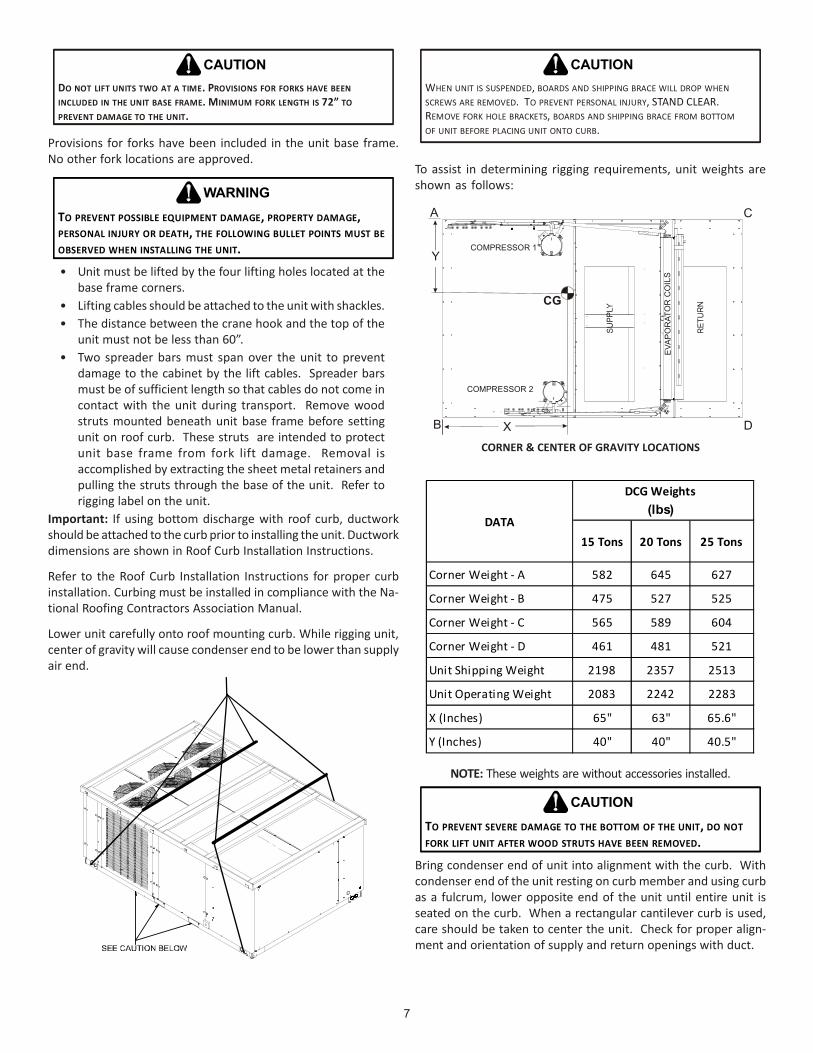
• Unit must be lifted by the four lifting holes located at thebase frame corners.
• Lifting cables should be attached to the unit with shackles.• The distance between the crane hook and the top of the
unit must not be less than 60”.• Two spreader bars must span over the unit to prevent
damage to the cabinet by the lift cables. Spreader barsmust be of sufficient length so that cables do not come incontact with the unit during transport. Remove woodstruts mounted beneath unit base frame before settingunit on roof curb. These struts are intended to protectunit base frame from fork lift damage. Removal isaccomplished by extracting the sheet metal retainers andpulling the struts through the base of the unit. Refer torigging label on the unit.
Important: If using bottom discharge with roof curb, ductworkshould be attached to the curb prior to installing the unit. Ductworkdimensions are shown in Roof Curb Installation Instructions.
Refer to the Roof Curb Installation Instructions for proper curbinstallation. Curbing must be installed in compliance with the Na-tional Roofing Contractors Association Manual.
Lower unit carefully onto roof mounting curb. While rigging unit,center of gravity will cause condenser end to be lower than supplyair end.
WHEN UNIT IS SUSPENDED, BOARDS AND SHIPPING BRACE WILL DROP WHEN SCREWS ARE REMOVED. TO PREVENT PERSONAL INJURY, STAND CLEAR.REMOVE FORK HOLE BRACKETS, BOARDS AND SHIPPING BRACE FROM BOTTOMOF UNIT BEFORE PLACING UNIT ONTO CURB.
CAUTION
To assist in determining rigging requirements, unit weights areshown as follows:
COMPRESSOR 1
COMPRESSOR 2
CG
EVAP
OR
ATO
R C
OIL
S
A
B
C
X D
Y
CORNER & CENTER OF GRAVITY LOCATIONS
(lbs)
Corner Weight - A 582 645 627
Corner Weight - B 475 527 525
Corner Weight - C 565 589 604
Corner Weight - D 461 481 521
Unit Shipping Weight 2198 2357 2513
Unit Operating Weight 2083 2242 2283
X (Inches) 65" 63" 65.6"
Y (Inches) 40" 40" 40.5"
DATA15 Tons 20 Tons 25 Tons
DCG Weights
NOTE: These weights are without accessories installed.
TO PREVENT SEVERE DAMAGE TO THE BOTTOM OF THE UNIT, DO NOT FORK LIFT UNIT AFTER WOOD STRUTS HAVE BEEN REMOVED.
CAUTION
Bring condenser end of unit into alignment with the curb. Withcondenser end of the unit resting on curb member and using curbas a fulcrum, lower opposite end of the unit until entire unit isseated on the curb. When a rectangular cantilever curb is used,care should be taken to center the unit. Check for proper align-ment and orientation of supply and return openings with duct.

8
RIGGING REMOVAL
TO PREVENT DAMAGE TO THE UNIT, DO NOT ALLOW CRANE HOOKS AND SPREADER BARS TO REST ON THE ROOF OF THE UNIT.
CAUTION
Remove spreader bars, lifting cables and other rigging equipment.
ELECTRICAL WIRING
HIGH VOLTAGE !DISCONNECT ALL POWER BEFORE SERVICING OR INSTALLING THIS UNIT. MULTIPLE POWER SOURCES MAY BE PRESENT. FAILURE TO DO SO MAY CAUSE PROPERTY DAMAGE, PERSONAL INJURY OR DEATH.
WARNING
HIGH VOLTAGE !TO AVOID PERSONAL INJURY OR DEATH DUE TO ELECTRICAL SHOCK, DO NOT TAMPER WITH FACTORY WIRING. THE INTERNAL POWER AND CONTROL WIRING OF THESE UNITS ARE FACTORY-INSTALLED AND HAVE BEEN THOROUGHLY TESTED PRIOR TO SHIPMENT. CONTACT YOUR LOCAL REPRESENTATIVE IF ASSISTANCE IS REQUIRED.
WARNING
TO PREVENT DAMAGE TO THE WIRING, PROTECT WIRING FROM SHARP EDGES. FOLLOW NATIONAL ELECTRICAL CODE AND ALL LOCAL CODES AND ORDINANCES. DO NOT ROUTE WIRES THROUGH REMOVABLE ACCESS PANELS.
CAUTION
CONDUIT AND FITTINGS MUST BE WEATHER-TIGHT TO PREVENT WATER ENTRY INTO THE BUILDING.
CAUTION
For unit protection, use a fuse or HACR circuit breaker that is inexcess of the circuit ampacity, but less than or equal to the maxi-mum overcurrent protection device. DO NOT EXCEED THE MAXI-MUM OVERCURRENT DEVICE SIZE SHOWN ON UNIT DATA PLATE.
All line voltage connections must be made through weatherprooffittings. All exterior power supply and ground wiring must be inapproved weatherproof conduit.
The main power supply wiring to the unit and low voltage wiringto accessory controls must be done in accordance with these in-structions, the latest edition of the National Electrical Code (ANSI/NFPA 70), and all local codes and ordinances.
The main power supply shall be three-phase, three wire. The unitis factory wired for the voltage shown on the unit’s data plate.
NOTE: If supply voltage is 208V, all leads on primary oftransformer(s) must be moved from the 230V to the 208V tap.
Main power wiring should be sized for the minimum circuitampacity shown on the unit’s database. Size wires in accordance
with the ampacity tables in Article 310 of the National ElectricalCode. If long wires are required, it may be necessary to increasethe wire size to prevent excessive voltage drop. Wires should besized for a maximum of 3% voltage drop.
TO AVOID PROPERTY DAMAGE OR PERSONAL INJURY DUE TO FIRE, USE ONLY COPPER CONDUCTORS.
CAUTION
TO PREVENT IMPROPER AND DANGEROUS OPERATION DUE TO WIRING ERRORS, LABEL ALL WIRES PRIOR TO DISCONNECTION WHEN SERVICING CONTROLS. VERIFY PROPER OPERATION AFTER SERVICING.
CAUTION
NOTE: A weather-tight disconnect switch, properly sized for theunit total load, must be field or factory installed. An external fieldsupplied disconnect may be mounted on the exterior panel.
Ensure the data plate is not covered by the field-supplieddisconnect switch.
• Some disconnect switches are not fused. Protect thepower leads at the point of distribution in accordance withthe unit data plate.
• The unit must be electrically grounded in accordance withlocal codes or, in the absence of local codes, with the latestedition of the National Electrical Code (ANSI-NFPA 70). Aground lug is provided for this purpose. Size groundingconductor in accordance with Table 250-95 of the NationalElectrical Code. Do not use the ground lug for connectinga neutral conductor.
• Connect power wiring to the electrical middle contactorwithin the main control box of power block, if equipped.
Low VoltageTerminal Strip
Thermostat wiringfor all unitsconnect to lowvoltage strip
GroundLug
Line voltage connectsto power block onCoolers, 230V Gas Packs, and 2 SpeedModels.
Line voltage connectsto middle contactoron 460v and 575vGas Packs(or power blockif equipped)
Power Block -(Coolers, 230V Gas Packs, and 2 SpeedModels)
Field wiring entersfrom this direction
POWER AND LOW VOLTAGE BLOCK LOCATIONS

9
Route fieldcontrol wiringthroughgrommet
Field connection forcontrol wiringat terminal block
Fieldconnectionforline voltage
Ground Lug
Field wiringenters fromthis direction
LOW
HIGH
25 TONS MODEL POWER AND LOW VOLTAGE BLOCK LOCATIONS
NOTE: Depending on the options installed, the location of thecomponents may vary in some models.
FAILURE OF UNIT DUE TO OPERATION ON IMPROPER LINE VOLTAGE OR WITH EXCESSIVE PHASE UNBALANCE CONSTITUTES PRODUCT ABUSE AND IS NOT COVERED BY THE WARRANTY. IT MAY CAUSE SEVERE DAMAGE TO THE UNIT ELECTRICAL COMPONENTS.
WARNING
AREAS WITHOUT CONVENIENCE OUTLET
It is recommended that an independent 115V power source bebrought to the vicinity of the roof top unit for portable lights andtools used by the service mechanic.
NOTE: Refer to local codes for requirements. These outlets canalso be factory installed.
UNITS INSTALLED ON ROOF TOPS
Main power and low voltage wiring may enter the unit throughthe side or through the roof curb. Install conduit connectors atthe desired entrance locations. External connectors must beweatherproof. All holes in the unit base must be sealed (includingthose around conduit nuts) to prevent water leakage into build-ing. All required conduit and fittings are to be field supplied.
Supply voltage to roof top unit must not vary by more than 10% ofthe value indicated on the unit data plate. Phase voltage unbal-ance must not exceed 2%. Contact your local power company forcorrection of improper voltage or phase unbalance.
ELECTRICAL ENTRANCE LOCATIONS
Unit is equipped with a Low Voltage Terminal Block and has SinglePoint wiring to the contactor.
LOW VOLTAGE CONTROL WIRING
1. A 24V thermostat must be installed for unit operation. Itmay be purchased with the unit or field -supplied.Thermostats may be programmable or electromechanicalas required.
2. Locate thermostat or remote sensor in the conditionedspace where it will sense average temperature. Do notlocate the device where it may be directly exposed tosupply air, sunlight or other sources of heat. Followinstallation instructions packaged with the thermostat.
3. Use #18 AWG wire for 24V control wiring runs notexceeding 75 feet. Use #16 AWG wire for 24V control wiringruns not exceeding 125 feet. Use #14 AWG wire for 24Vcontrol wiring runs not exceeding 200 feet. Low voltagewiring may be National Electrical Code (NEC) Class 2 wherepermitted by local codes.
4. Route thermostat wires from sub-base terminals to theunit. Control wiring should enter through the duct panel(dimple marks entrance location). Connect thermostat andany accessory wiring to low voltage terminal block TB1 inthe main control box.
NOTE: Field-supplied conduit may need to be installeddepending on unit/curb configuration. Use #18 AWG solidconductor wire whenever connecting thermostat wires toterminals on sub-base. DO NOT use larger than #18 AWG wire. Atransition to #18 AWG wire may be required before enteringthermostat sub-base.
NOTE: Refer to unit wiring diagrams for thermostat hookups.

10
GAS SUPPLY PIPING
TO PREVENT PERSONAL INJURY OR DEATH DUE TO IMPROPER INSTALLATION, ADJUSTMENT, ALTERATION, SERVICE OR MAINTENANCE, REFER TO THIS MANUAL. FOR ADDITIONAL ASSISTANCE OR INFORMATION, CONSULT A QUALIFIED INSTALLER, SERVICE AGENCY OR THE GAS SUPPLIER.
WARNING
IMPORTANT NOTE: This unit is factory set to operate on naturalgas at the altitudes shown on the rating plate.
TO PREVENT PROPERTY DAMAGE, PERSONAL INJURY OR DEATH WHEN EITHER USING PROPANE GAS ALONE OR AT HIGHER ALTITUDES, OBTAIN AND INSTALL THE PROPER CONVERSION KIT(S). FAILURE TO DO SO CAN RESULT IN UNSATISFACTORY OPERATION AND/OR EQUIPMENT DAMAGE. HIGH ALTITUDE KITS ARE FOR U.S. INSTALLATIONS ONLY AND ARE NOT APPROVED FOR USE IN CANADA.
WARNING
The rating plate is stamped with the model number, type of gasand gas input rating. Make sure the unit is equipped to operate onthe type of gas available. Conversion to propane (LP) gas is permit-ted with the use of the factory authorized conversion kit (see theunit Technical Manual for the appropriate kit). For High Altitudederates, refer to the latest edition of the National Fuel Gas CodeNFPA 54/ANSI Z223.1.
NATURAL Min. 5.0" W.C., Max. 10.0" W.C.
PROPANE Min. 11.0" W.C., Max. 14.0" W.C.
INLET GAS PRESSURE
Inlet Gas Pressure Must Not Exceed the Maximum Value Shown in Table Above.
The minimum supply pressure should not vary from that shown inthe table above because this could prevent the unit from havingdependable ignition. In addition, gas input to the burners mustnot exceed the rated input shown on the rating plate. Overfiringof the unit could result in premature heat exchanger failure.
PIPING
IMPORTANT NOTE: To avoid possible unsatisfactory operation orequipment damage due to under firing of equipment, do not un-dersize the natural/propane gas piping from the meter/tank to theunit. When sizing a trunk line, include all appliances on that linethat could be operated simultaneously.
The rating plate is stamped with the model number, type of gasand gas input rating. Make sure the unit is equipped to operate onthe type of gas available. The gas line installation must complywith local codes, or in the absence of local codes, with the latestedition of the National Fuel Gas Code NFPA 54/ANSI Z223.1.
Natural Gas Connection
1/2 3/4 1 1 1/4 1 1 /210 132 278 520 1050 160020 92 190 350 730 110030 73 152 285 590 98040 63 130 245 500 76050 56 115 215 440 67060 50 105 195 400 61070 46 96 180 370 56080 43 90 170 350 53090 40 84 160 320 490
100 38 79 150 305 460Pressure= .50 PSIG or less and Pressure Drop of 0.3" W.C.(Based on 0.60 Specific Gravity Gas)
Natural Gas Capacity of Pipein Cubic Feet of Gas Per Hour (CFH)
Nominal Black Pipe Size (inches)Length ofPipe in Feet
Heating Value of Gas (BTU/Cubic FootCFH =
BTUH Furnace Input
Refer to the Proper Piping Practice drawing for the general layoutat the unit. The following rules apply:
1. Use black iron pipe and fittings for the supply piping. Theuse of a flex connector and/or copper piping is permittedas long as it is in agreement with local codes.
2. Use pipe joint compound on male threads only. Pipe jointcompound must be resistant to the action of the fuel used.
3. Use ground joint unions.4. Install a drip leg to trap dirt and moisture before it can
enter the gas valve. The drip leg must be a minimum ofthree inches long.
5. Use two pipe wrenches when making connection to thegas valve to keep it from turning.
6. Install a manual shut-off valve in a convenient location(within six feet of unit) between the meter and the unit.
7. Tighten all joints securely.8. The unit must be connected to the building piping by one
of the following methods:• Rigid metallic pipe and fittings• Semirigid metallic tubing and metallic fittings
(Aluminum alloy tubing must not be used in exteriorlocations)
• Listed gas appliance connectors used in accordance withthe terms of their listing that are completely in the sameroom as the equipment
• In the prior two methods above the connector or tubingmust be protected from physical and thermal damage.Aluminum alloy tubing and connectors must be coatedto protect against external corrosion when in contact withmasonry, plaster or insulation or are subject to repeatedwettings by liquids (water - not rain water, detergents orsewage).
11
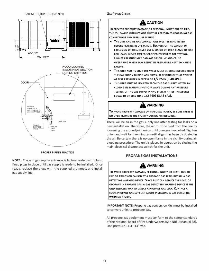
46-1/10”
GAS INLET LOCATION (3/4” NPT)
46-1/10”46-1/10”74-11/12”
HOOD LOCATEDINSIDE HEAT SECTIONDURING SHIPPING
DOOR
PROVIDECLEARANCEFOR REMOVAL OFACCESS PANELS
DRIP LEG
GROUNDJOINTUNION
MANUALSHUT OFFVALVE
PROPER PIPING PRACTICE
NOTE: The unit gas supply entrance is factory sealed with plugs.Keep plugs in place until gas supply is ready to be installed. Onceready, replace the plugs with the supplied grommets and installgas supply line.
GAS PIPING CHECKS
TO PREVENT PROPERTY DAMAGE OR PERSONAL INJURY DUE TO FIRE, THE FOLLOWING INSTRUCTIONS MUST BE PERFORMED REGARDING GAS CONNECTIONS AND PRESSURE TESTING: • THE UNIT AND ITS GAS CONNECTIONS MUST BE LEAK TESTED
BEFORE PLACING IN OPERATION. BECAUSE OF THE DANGER OF EXPLOSION OR FIRE, NEVER USE A MATCH OR OPEN FLAME TO TEST FOR LEAKS. NEVER EXCEED SPECIFIED PRESSURES FOR TESTING. HIGHER PRESSURE MAY DAMAGE GAS VALVE AND CAUSE OVERFIRING WHICH MAY RESULT IN PREMATURE HEAT EXCHANGE FAILURE.
• THIS UNIT AND ITS SHUT-OFF VALVE MUST BE DISCONNECTED FROM THE GAS SUPPLY DURING ANY PRESSURE TESTING OF THAT SYSTEM AT TEST PRESSURES IN EXCESS OF 1/2 PSIG (3.48 KPA).
• THIS UNIT MUST BE ISOLATED FROM THE GAS SUPPLY SYSTEM BY CLOSING ITS MANUAL SHUT-OFF VALVE DURING ANY PRESSURE TESTING OF THE GAS SUPPLY PIPING SYSTEM AT TEST PRESSURES EQUAL TO OR LESS THAN 1/2 PSIG (3.48 KPA).
CAUTION
TO AVOID PROPERTY DAMAGE OR PERSONAL INJURY, BE SURE THERE IS IN THE VICINITY DURING AIR BLEEDING.NO OPEN FLAME
WARNING
There will be air in the gas supply line after testing for leaks on anew installation. Therefore, the air must be bled from the line byloosening the ground joint union until pure gas is expelled. Tightenunion and wait for five minutes until all gas has been dissipated inthe air. Be certain there is no open flame in the vicinity during airbleeding procedure. The unit is placed in operation by closing themain electrical disconnect switch for the unit.
PROPANE GAS INSTALLATIONS
TO AVOID PROPERTY DAMAGE, PERSONAL INJURY OR DEATH DUE TO FIRE OR EXPLOSION CAUSED BY A PROPANE GAS LEAK, INSTALL A GAS DETECTING WARNING DEVICE. SINCE RUST CAN REDUCE THE LEVEL OF ODORANT IN PROPANE GAS, A GAS DETECTING WARNING DEVICE IS THE ONLY RELIABLE WAY TO DETECT A PROPANE GAS LEAK. CONTACT A LOCAL PROPANE GAS SUPPLIER ABOUT INSTALLING A GAS DETECTING WARNING DEVICE.
WARNING
IMPORTANT NOTE: Propane gas conversion kits must be installedto convert units to propane gas.
All propane gas equipment must conform to the safety standardsof the National Board of Fire Underwriters (See NBFU Manual 58).Line pressure 11.3 - 14” w.c.

12
For satisfactory operation, propane gas manifold pressure mustbe within 9.7 - 10.3 inches w.c. for high fire and within 6.7 - 7.3inches w.c. low fire at the manifold with all gas appliances in op-eration. Maintaining proper gas pressure depends on three mainfactors:
1. Vaporization rate, which depends on (a) temperature ofthe liquid, and (b) wetted surface area of the container orcontainers.
2. Proper pressure regulation.3. Pressure drop in lines between regulators, and between
second stage regulator and the appliance. Pipe sizerequired will depend on length of pipe run and total loadof all appliances.
TANKS AND PIPING
Complete information regarding tank sizing for vaporization,recommended regulator settings and pipe sizing is availablefrom most regulator manufacturers and propane gas suppliers.Since propane gas will quickly dissolve white lead or moststandard commercial compounds, special pipe dope must beused. Shellac base compounds resistant to the actions ofliquefied petroleum gases such as Gasolac®, Stalactic®, Clyde’s®
or John Crane® are satisfactory.See following figure for typical propane gas piping.
200 PSIGMaximum
5 to 15 PSIG(20 PSIG Max.)
Continuous11" W.C.
Second StageRegulator
First StageRegulator
TYPICAL PROPANE GAS PIPING
ROOF TOP LOCATION AND INSTALLATION
The gas supply piping location and installation for roof top unitsmust be in accordance with local codes or, in the absence of localscodes, with ordinances of the latest edition of the National FuelGas Code (ANSI Z223.1).
A manual gas shut off valve must be field installed external to theroof top unit. In addition, a drip leg must be installed near theinlet connection. A ground joint union connection is required be-tween the external shut off valve and the unit connection to thegas valve to permit removal of the burner assembly for servicing.
1. Route gas piping to unit so that it does not interfere withthe removal of access panels. Support and align piping toprevent strains or misalignment of the manifold assembly.
2. All units are furnished with standard female NPT pipeconnections. Connection pipe size is 3/4" NPT. The size ofthe gas supply piping to the unit must be based on lengthof run, number of units on the system, gas characteristics,
BTU requirement and available supply pressure. All pipingmust be done in accordance with local codes or, in theabsence of local codes, with the latest edition of theNational Fuel Gas Code (ANSI Z223.1).NOTE: The gas connection size at the unit does NOTestablish the size of the supply line.
3. These units are designed for either natural or propane(LP) gas and are specifically constructed at the factory foronly one of these fuels. The fuels are NOT interchangeable.However, the furnace can be converted in the field fromnatural gas to LP gas with the appropriate factory kit (seeunit Technical Manual for the appropriate kit). Only aqualified contractor, experienced with natural and propanegas systems, should attempt conversion. Kit instructionsmust be followed closely to assure safe and reliable unitoperation.
4. With all units on a common line operating under full fire,natural gas main supply pressure should be adjusted toapproximately 7.0" w.c., measured at the unit gas valve. Ifthe gas pressure at the unit is greater than 10.5" w.c., thecontractor must furnish and install an external typepositive shut off service pressure regulator. The unit willnot function satisfactorily if supply gas pressure is less than5.5" w.c. or greater than 10.5" w.c..NOTE: A minimum horizontal distance of 48" betweenthe regulator and the furnace flue discharge is required.
5. With all units on a common line operating under full LPgas main supply pressure should be at least 11.0" w.c. andmust be no greater than 14.0" w.c., measured at the unitgas valve. Unit will not function satisfactorily if supply gaspressure is less than 11.0" w.c. or greater than 14.0" w.c..
6. All pipe connections should be sealed with a pipe threadcompound, which is resistant to the fuel used with thefurnace. A soapy water solution should be used to checkall joints for leaks. A 1/8" NPT plugged tap is located onthe entering side of the gas valve for test gauge connectionto measure supply (main) gas pressure. Another 1/8" tapis provided on the side of the manifold for checkingmanifold pressure.
THIS UNIT AND ITS INDIVIDUAL SHUTOFF VALVE MUST BE DISCONNECTED FROM THE GAS SUPPLY SYSTEM DURING ANY PRESSURE TESTING OF THAT SYSTEM AT TEST PRESSURES IN EXCESS OF 1/2 PSIG (13.8” W.C.).
WARNING
THIS UNIT MUST BE ISOLATED FROM THE GAS SUPPLY PIPING SYSTEM BY CLOSING ITS INDIVIDUAL MANUAL SHUTOFF VALVE DURING ANY PRESSURE TESTING EQUAL TO OR LESS THAN 1/2 PSIG.
CAUTION
7. There must be no obstruction to prevent the flow ofcombustion and ventilating air. A vent stack is not requiredand must never be used. The power ventor will supply anadequate amount of combustion air as long as the airpassageways are kept free of any obstructions and therecommended external unit clearances are maintained.

13
CIRCULATING AIR AND FILTERSDUCTWORK
The supply duct should be provided with an access panel largeenough to inspect the air chamber downstream of the heat ex-changer. A cover should be tightly attached to prevent air leaks.
Ductwork dimensions are shown in the roof curb installationmanual.
If desired, supply and return duct connections to the unit may bemade with flexible connections to reduce possible unit operatingsound transmission.
VENTING
NOTE: Venting is self-contained.
CONDENSATE DRAIN CONNECTION
CONDENSATE DRAIN CONNECTION
A 1” female NPT drain connection is supplied on the end of thecondensate pan, with an alternative connection on the bottom ofthe pan. An extrnal trap must be installed for proper condensatedrainage.
Drain Pan (Side View)
NOTE: Trap should be deep enough to offset maximumunit static difference. A minimum 4” trap is recommended.
Drain Plug Roof Curb
See NOTE
Base Rail
Open Vent 2” Min
DRAIN CONNECTION
Install condensate drain trap as shown. Use 1" drain line andfittings or larger. Do not operate without trap.
HORIZONTAL DRAIN
Drainage of condensate directly onto the roof may be acceptable;(refer to local code). It is recommended that a small drip pad ofeither stone, mortar, wood or metal be provided to prevent anypossible damage to the roof. When using the horizontal drainconnection, check the drain plug in bottom connection to ensureit is tight.
CLEANING
Due to the fact that drain pans in any air conditioning unit willhave some moisture in them, algae and fungus will grow due toairborne bacteria and spores. Periodic cleaning is necessary toprevent this build-up from plugging the drain.
STARTUP, ADJUSTMENTS, AND CHECKS
HIGH VOLTAGE!TO AVOID PERSONAL INJURY OR DEATH DUE TO ELECTRICAL SHOCK, BOND THE FRAME OF THIS UNIT TO THE BUILDING ELECTRICAL GROUND BY USE OF THE GROUNDING TERMINAL PROVIDED OR OTHER ACCEPTABLE MEANS. DISCONNECT ALL POWER BEFORE SERVICING OR INSTALLING THIS UNIT.
WARNING
PRE-STARTUP INSTRUCTIONS - GENERAL
TO PREVENT PROPERTY DAMAGE OR PERSONAL INJURY, DO NOT START THE UNIT UNTIL ALL NECESSARY PRE-CHECKS AND TEST HAVE BEEN PERFORMED.
CAUTION
Prior to the beginning of Startup, Adjustments, and Checks proce-dures, the following steps should be completed in the building.
MOVING MACHINERY HAZARD!TO PREVENT POSSIBLE PERSONAL INJURY OR DEATH, DISCONNECT POWER TO THE UNIT AND PADLOCK IN THE “OFF” POSITION BEFORE SERVICING FANS.
WARNING
This unit is equipped with an electronic ignition device to auto-matically light the main burners. It also has a power vent blowerto exhaust combustion products.
On new installations, or if a major component has been replaced,the operation of the unit must be checked.
Check unit operation as outlined in the following instructions. Ifany sparking, odors, or unusual sounds are encountered, shut offelectrical power and recheck for wiring errors, or obstructions inor near the blower motors. Duct covers must be removed beforeoperating unit.
The Startup, Adjustments, and Checks procedure provides a step-by-step sequence which, if followed, will assure the proper startupof the equipment in the minimum amount of time. Air balancingof duct system is not considered part of this procedure. However,it is an important phase of any air conditioning system startupand should be performed upon completion of the Startup, Adjust-ments, and Checks procedure. The Startup, Adjustments, and Checksprocedure at outside ambients below 55°F should be limited to areadiness check of the refrigeration system with the required fi-nal check and calibration left to be completed when the outsideambient rises above 55°F.

14
TEMPORARY HEATING OR COOLING
If the unit is to be used for temporary heating or cooling, a “Startup,Adjustments, and Checks” must first be performed in accordancewith this manual. Damage or repairs due to failure to comply withthese requirements are not covered under the warranty. After themachines are used for temporary heating or cooling, inspect thecoils, fans, and motors for unacceptable levels of constructiondust and dirt and install new filters.
CONTRACTOR RESPONSIBILITY
The installing contractor must be certain that:
• All supply and return air ductwork is in place, properlysealed, and corresponds with installation instructions.
• All thermostats are mounted and wired in accordancewith installation instructions.
• All electric power, all gas, hot water or steam lineconnections, and the condensate drain installation havebeen made to each unit on the job. These main supplylines must be functional and capable of operating all unitssimultaneously.
• Requirements are met for venting and combution air.• Air filters are in place.• Input rate and temperature rise are adjusted per rating
plate.
ROOF CURB INSTALLATION CHECK
Inspect the roof curb for correct installation. The unit and curbassembly should be level. Inspect the flashing of the roof mount-ing curb to the roof, especially at the corners, for good workman-ship. Also check for leaks around gaskets. Note any deficiencies ina separate report and forward to the contractor.
OBSTRUCTIONS, FAN CLEARANCE AND WIRING
Remove any extraneous construction and shipping materials thatmay be found during this procedure. Rotate all fans manually tocheck for proper clearances and that they rotate freely. Check forbolts and screws that may have jarred loose during shipment tothe job site. Retighten if necessary. Re-tighten all electrical con-nections.
FIELD DUCT CONNECTIONS
Verify that all duct connections are tight and that there is no airbypass between supply and return.
FILTER SECTION CHECK
Remove filter section access panels and check that filters are prop-erly installed. Note airflow arrows on filter frames.
PRE-STARTUP PRECAUTIONS
It is important to your safety that the unit has been properlygrounded during installation. Check ground lug connection in maincontrol box for tightness prior to closing circuit breaker or discon-nect switch. Verify that supply voltage on line side of disconnectagrees with voltage on unit identification plate and is within theutilization voltage range as indicated in Appendix C Electrical Data.
System Voltage - That nominal voltage value assigned to a circuitor system for the purpose of designating its voltage class.
Nameplate Voltage - That voltage assigned to a piece of equip-ment for the purpose of designating its voltage class and for thepurpose of defining the minimum and maximum voltage at whichthe equipment will operate.
Utilization Voltage - The voltage of the line terminals of the equip-ment at which the equipment must give fully satisfactory perfor-mance. Once it is established that supply voltage will be main-tained within the utilization range under all system conditions,check and calculate if an unbalanced condition exists betweenphases. Calculate percent voltage unbalance as follows:
Three Phase Models
3) PERCENT VOLTAGE UNBALANCE
2) MAXIMUM VOLTAGE DEVIATIONSFROM AVERAGE VOLTAGE
1) AVERAGE VOLTAGE
HOW TO USE THE FORMULA:EXAMPLE: With voltage of 220, 216, and 2131) Average Voltage = 220+216+213=649 / 3 = 2162) Maximum Voltage Deviations from Average Voltage = 220 - 216 = 4
3) Percent Voltage Unbalance = 100 x = = 1.8%
Percent voltage unbalance MUST NOT exceed 2%.
4216
400216
= 100 X
CONTROL VOLTAGE CHECK
Close the disconnect switch to energize control transformer. Checkprimary and secondary (24V) of control transformer.
AIR FLOW ADJUSTMENTS
Refer to the following “Motor Sheave Adjustments” section.
When the final adjustments are complete, the current draw of themotor should be checked and compared to the full load currentrating of the motor. The amperage must not exceed the servicefactor stamped on the motor nameplate. The total airflow mustnot be less than that required for operation of the electric heatersor the furnace.
If an economizer is installed, check the unit operating balance withthe economizer at full outside air and at minimum outside air.
NOTE: Airflow setting below 300 CFM/Ton is not recommended, asevaporator freezing or poor unit performance is possible.
For 2-speed models, airflow adjustments must be made with theevaporator motor operating at high speed (in 2nd stage cooling orin heat mode). 2-speed models have a “V” in 11th digit of themodel number (e.g. DCC300XXX3V).

15
EVAPORATOR FAN ROTATION CHECK
Check that fan rotates clockwise when viewed from the drive sideof unit and in accordance with rotation arrow shown on blowerhousing. If it does not, reverse any two incoming power cables atSingle Point Power Block. In this case, repeat bearing check.
Do not attempt to change load side wiring. Internal wiring assuresall motors and compressors will rotate in correct direction onceevaporator fan motor rotation check has been made.
ELECTRICAL INPUT CHECK
Make preliminary check of evaporator fan ampere draw and verifythat motor nameplate amps are not exceeded. A final check ofamp draw should be made upon completion of air balancing ofthe duct system (see Appendix C).
SET EVAPORATOR FAN RPM
Actual RPM’s must be set and verified with a tachometer or strobelight. Refer to Appendices A and B for basic unit fan RPM. Referalso to “Airflow” section of this manual. With disconnect switchopen, disconnect thermostat wires from terminals Y and W. Thiswill prevent heating and mechanical cooling from coming on. Placea jumper wire across terminals R and G at TB1 terminal block. Closedisconnect switch; evaporator fan motor will operate so RPM canbe checked.
For gas heat units, the airflow must be adjusted so that the airtemperature rise falls within the ranges given stated on Data Plate(see Appendix A - Blower Performance).
BELT DRIVE MODELS ONLYThe drive on the supply fan is typically set in the middle of theRPM range. The drive motor sheave pitch diameter is field adjust-able for the required airflow. Refer to “Motor Sheave Adjustments”section.
Upon completion of the air flow balancing, we recommend re-placing the variable pitched motor sheave with a properly-sizedfixed sheave. A matching fixed sheave will provide longer belt andbearing life and vibration free operation. Initially, it is best to havea variable pitched motor sheave for the purpose of airflow balanc-ing, but once the balance has been achieved, fixed sheaves main-tain alignment and minimize vibration more effectively. For directdrive units, move fan speed wire.
BEARING CHECK
Prior to energizing any fans, check and make sure that all setscrewsare tight so that bearings are properly secured to shafts.
TENSION AND ALIGNMENT ADJUSTMENT
Correct belt tension is very important to the life of your belt. Tooloose a belt will shorten its life; too tight, premature motor andbearing failure will occur. Check you belt drive for adequate “run-in” belt tension by measuring the force required to deflect thebelt at the midpoint of the span length. Belt tension force can bemeasured using a belt tension gauge, available through most beltdrive manufacturers.
SPAN LENGTH t*DEFLECTION
FORCE
h
C
dH
D
*Apply force to the center of the span.
t = Span length, inchesC = Center distance, inchesD = Larger sheave diameter, inchesd = Smaller sheave diameter, inchesh = Deflection height, inches
DRIVE BELT TENSION ADJUSTMENT
MODELSHEAVE
DIAMETER (in)
DEFLECTION(in)
BELT DRIVE Used New
15 Ton B, BA Standard 4.3 to 5.5 5.5 + .5 8.2 + .5 1/4 ± 1/16
20 Ton B, BA Standard 4.3 to 5.5 5.5 + .5 8.2 + .5 1/4 ± 1/16
25 Ton B, BA Standard 5.1 to 6.1 5.5 + .5 8.2 + .5 1/4 ± 1/16
DEFLECTIONFORCE (lbs)TYPE
RECOMMENDED POUNDS OF FORCE PER BELT
When new V-belts are installed on a drive the initial tension willdrop rapidly during the first few hours. Check tension frequentlyduring the first 24 hours of operation. Subsequent retensioningshould fall between the minimum and maximum force. To deter-mine the deflection distance from the normal position, use astraightedge or stretch a cord from sheave to sheave to use as areference line. On multiple belt drives, an adjacent undeflectedbelt can be used as a reference.
MOTOR SHEAVE ADJUSTMENTS
VL, VM & 2VP VARIABLE PITCH KEY TYPE MOTOR SHEAVES
The driving and driven motor sheaves should be in alignment witheach other and the shafts parallel.
VL & VM SHEAVES ADJUSTMENT
1. Loosen set screw “B” using a 5/32" Allen key.2. Making half or full turns from closed position, adjust
sheave pitch diameter for desired speed. DO NOT OPENMORE THAN SIX FULL TURNS.
3. Tighten set screw “B” securely over flat.4. Carefully put on belts and adjust belt tension. DO NOT
FORCE BELTS OVER GROOVES.

16
5. Ensure all keys are in place and the set screws tight beforestarting drive. Recheck set screws and belt tension after24 hours service.
NOTE: Future adjustments should be made by loosening the belttension and increasing or decreasing the pitch diameter of thesheave by half or full turns as required. Readjust belt tension beforestarting drive.
C
B
VL & VM
NOTE: Do not operate sheave with flange projecting beyond thehub end.
GAS SYSTEM CHECK
Pre-Operation Checks
1. Close the manual gas valve external to the unit.2. Turn off the electrical power supply to the unit.3. Set the room thermostat to its lowest possible setting.4. Remove the heat exchanger door on the side of the unit
by removing screws.5. This unit is equipped with an ignition device which
automatically lights the main burner. DO NOT try to lightburner by any other method.
6. Move the gas control valve switch to the OFF position. Donot force.
7. Wait five minutes to clear out any gas.8. Smell for gas, including near the ground. This is important
because some types of gas are heavier than air. If you havewaited five minutes and you do smell gas, immediatelyfollow the warnings on page 3 of this manual. If havingwaited for five minutes and no gas smell is noted, movethe gas control valve switch to the ON position.
9. Replace the heat exchanger door on the side of the unit.10. Open the manual gas valve external to the unit.11. Turn on the electrical power supply to the unit.12. Set the thermostat to desired setting.
GAS SUPPLY PRESSURES & REGULATOR ADJUSTMENTS
SHOULD OVERHEATING OCCUR OR THE GAS SUPPLY FAIL TO SHUT OFF, TURN OFF THE MANUAL GAS SHUTOFF VALVE EXTERNAL TO THE UNIT BEFORE TURNING OFF THE ELECTRICAL SUPPLY.
WARNING
TO AVOID PROPERTY DAMAGE, PERSONAL INJURY OR DEATH, DO NOT FIRE GAS UNIT WITH FLUE BOX COVER REMOVED.
WARNING
NOTE: Except during brief periods when gas pressures are beingmeasured by qualified service personnel, the furnace access panelmust always be secured in place when the furnace is in operation.An inspection port in the access panel is provided to monitor theflame.The first step in checking out the gas-fired furnace is to test thegas supply piping to the unit for tightness and purge the system ofair using methods outlined in the latest edition of the NationalFuel Gas Code ANSI Z223.1. Verify that the disconnect switch is inthe “OFF” position. A soapy water solution should be used to checkfor gas leaks. Since the unit is subject to considerable jarring dur-ing shipment, it is extremely important that all gas connectionsand joints be tested for tightness. Gas piping downstream fromthe unit inlet should be checked for leaks during the subsequentsequence check.
The supply gas pressure should be adjusted to 7.0" w.c. on naturalgas and 11.0" on LP gas with the gas burners operating. If there ismore than one unit on a common gas line, the pressures shouldbe checked with all units under full fire. A supply pressure tap isprovided on the upstream side of the gas valve. A manifold pres-sure tap is provided on the manifold. The normal manifold pres-sure for full input is 3.5" w.c. on natural gas and 10.0" w.c. forpropane gas. Minimum gas supply pressure is 5.5" w.c. for naturalgas and 11.0" for propane gas. In order to obtain rating, gas supplypressure must be 11.0" w.c. for propane gas.
The pressure regulator on LP gas models is adjusted for 10.0" w.c.manifold pressure and is intended to prevent over-firing only. Donot attempt adjustment of the built-in pressure regulator unlessthe supply pressure is at least 7.0" w.c. on natural gas or 14.0" w.c.on propane gas. Check the location of the ignition electrode andthe flame sensor for correct gap setting.

17
FlameSensor
Ignitor
NATURAL PROPANE (LP)
350,000 7 50,000 #30 #48
400,000 8 50,000 #30 #48
GAS ORIFICESMAXIMUM INPUT (BTUH)
NUMBERof
BURNERS
MAXIMUMBTUH/BURNER
HEAT EXCHANGER AND BURNER ORIFICE SPECIFICATIONS
NOTE: Gas appliances located more than 2000 feet above sealevel must be derated 4% per 1000 feet of total elevation and thatvariance in gas heating value and specific gravity require changein manifold pressure to obtain rating, it is mandatory that the inputbe adjusted at the installation site. All installations should be madeas outlined in the latest edition of the National Fuel Gas Code ANSIZ223.1, section “Procedures To Be Followed To Place An Appliancein Operation”. Refer also to the “User’s Information Manual”supplied with the unit for additional information on the gas furnace.
Gas Supply And Manifold Check
Gas supply pressure and manifold pressure with the burners oper-ating must be as specified on the rating plate.
Gas Inlet Pressure Check
Gas inlet pressure must be checked and adjusted in accordance tothe type of fuel being consumed.
With Power And Gas Off:
1. Connect a water manometer or adequate gauge to theinlet pressure tap of the gas valve.Inlet gas pressure can also be measured by removing thecap from the dripleg and installing a predrilled cap with ahose fitting.
With Power And Gas On:
2. Put unit into heating cycle and turn on all other gasconsuming appliances.
NATURAL Min. 5.0" W.C., Max. 10.0" W.C.
PROPANE Min. 11.0" W.C., Max. 14.0" W.C.
INLET GAS PRESSURE
NOTE: Inlet Gas Pressure Must Not Exceed the Maximum ValueShown.If operating pressures differ from above, make necessary pressureregulator adjustments, check piping size, etc., and/or consult withlocal utility.
Manifold Pressure Check
The gas valve has a tapped opening to facilitate measurement ofthe manifold pressure. A “U” Tube manometer having a scale rangefrom 0 to 12 inches of water should be used for this measure-ment. The manifold pressure must be measured with the burnersoperating.
To adjust the pressure regulator, remove the adjustment screw orcover on the gas valve. Turn out (counterclockwise) to decreasepressure, turn in (clockwise) to increase pressure. Only small varia-tions in gas flow should be made by means of the pressure regula-tor adjustment. In no case should the final manifold pressure varymore than plus or minus 0.3 inches water column from the speci-fied nominal pressure. Any major changes in flow should be madeby changing the size of the burner orifices. The measured inputrate to the furnace must not exceed the rating specified on theunit rating plate.
For natural gas, the manifold pressure must be between 3.2 and3.8 inches w.c. (3.5 nominal) for high fire and between 1.7 and 2.3inches w.c. (2.0 nominal) for low fire.
For propane gas, the manifold pressure must be between 9.7 and10.3 inches w.c. (10.0 nominal) for high fire and between 6.7 and7.3 inches w.c. (7.0 nominal) for low fire.
Gas Input (Natural Gas Only) Check
It is the responsibility of the contractor to adjust the gas input tothe unit.
To measure the gas input use a gas meter and proceed asfollows:1. Turn off gas supply to all other appliances except the unit.2. With the unit operating, time the smallest dial on the
meter for one complete revolution. If this is a 2 cubic footdial, divide the seconds by 2; if it is a 1 cubic foot dial, usethe seconds as is. This gives the seconds per cubic foot ofgas being delivered to the unit.
3. INPUT=GAS HTG VALUE x 3600 / SEC. PER CUBIC FOOTExample: Natural gas with a heating value of 1000 BTU per cubicfoot and 34 seconds per cubic foot as determined by Step 2, then:
Input = 1000 x 3600 / 34 = 106,000 BTU per Hour. NOTE:BTU content of the gas should be obtained from the gassupplier. This measured input must not be greater thanshown on the unit rating plate.

18
Adjust input rate by varying the adjustment of the gas pressureregulator on the gas valve. All adjustments must be made withfurnace operating at high fire and at normal operating tempera-ture. A manometer should be connected to the gas valve to verifypressure is within the specified range (see following figures formanometer connections). Clockwise rotation of the pressure regu-lator screw increases pressure and gas flow rate. Turn screw coun-terclockwise to decrease pressure and gas flow rate. After adjust-ment the furnace temperature rise must be within the range speci-fied on the unit data plate. NOTE: Thermal efficiency of the fur-nace is a product efficiency rating determined under continuousoperating conditions independent of any installed system.
Pressure RegulatorAdjustment
(Under Cap Screw)
Gas ValveOn/Off
SelectorSwitch
INLET OUTLET
Inlet PressureTap
Outlet PressureTap
WHITE-RODGERS 36G22 - SINGLE STAGE
InletPressure Boss
Low FireRegulator Adjust
Manometer
ManometerHose
High Fire RegulatorAdjust Regulator
VentOutlet
Pressure Boss
Open toAtmosphere
WHITE-RODGERS 36G54 (2-STAGE) CONNECTED TO MANOMETER
PRESSURE ADJUSTMENTS
TO CONNECT MANOMETER TO GAS VALVE:1. Back outlet pressure test screw (inlet/outlet pressure boss)
out one turn (counterclockwise, not more than one turn).2. Attach a hose and manometer to the outlet pressure boss
of the valve.
TO REMOVE MANOMETER FROM GAS VALVE:1. Remove manometer hose from outlet pressure boss.2. Turn outlet pressure test screw in to seal pressure port
(clockwise, 7 in-lb. minimum).3. Turn on electrical power and gas supply to the system.4. Turn on system power and energize valve.
5. Using a leak detection solution or soap suds, check forleaks at pressure boss screw. Bubbles forming indicate aleak. SHUT OFF GAS AND FIX ALL LEAKS IMMEDIATELY.
TO PREVENT UNRELIABLE OPERATION OR EQUIPMENT DAMAGE, THE GAS MANIFOLD PRESSURE MUST BE AS SPECIFIED ON THE UNIT RATING PLATE. ONLY MINOR ADJUSTMENTS SHOULD BE MADE BY ADJUSTING THE GAS VALVE PRESSURE REGULATOR.
CAUTION
6. Relight all other appliances turned off in step 1. Be sure allpilot burners are operating.
Main Burner Flame Check
Flames should be stable, soft and blue (dust may cause orangetips but they must not be yellow) and extending directly outwardfrom the burner without curling, floating or lifting off.
Temperature Rise Check
Check the temperature rise through the unit by placing thermom-eters in supply and return air registers as close to the unit as pos-sible. Thermometers must not be able to sample temperature di-rectly from the unit heat exchangers, or false readings could beobtained.
1. All registers must be open; all duct dampers must be intheir final (fully or partially open) position and the unitoperated for 15 minutes on HIGH FIRE before takingreadings.
2. The temperature rise must be within the range specifiedon the rating plate.
NOTE: Air temperature rise is the temperature difference betweensupply and return air.With a properly designed system, the proper amount of tempera-ture rise will normally be obtained when the unit is operated atrated input with the recommended blower speed.
If the correct amount of temperature rise is not obtained, it maybe necessary to change the blower speed. A higher blower speedwill lower the temperature rise. A slower blower speed will in-crease the temperature rise.
NOTE: Blower speed MUST be set to give the correct airtemperature rise through the unit as marked on the rating plate.
NORMAL SEQUENCE OF OPERATION - HEATING
This unit has one (RS) Manual Reset Limit Control Switch. Checkthe limit to make sure it has not tripped. The limit may arrive atthe job site tripped as a result of shipping shock.
If the vent motor comes on, but the unit does not attempt igni-tion, check if the ALS (Automatic Reset High Limit Control Switch)requires resetting.

19
1. With electricity and gas turned on, the system switch inthe “HEAT” or “AUTO” position and the fan switch in the“AUTO” position, the thermostat will close the circuitbetween unit terminals R and W (R-W) when thetemperature falls below the thermostat setting.
2. D1 on IIC energizes relay VMR.3. Relay VMR energizes the vent motor.4. Operation of the vent motor closes the pressure switch PS
located in the burner compartment. the control theninitiates a 15-second pre-purge time delay. During thisperiod, the vent motor will clear the combustion chamberof any residual gas.
5. After the pre-purge period, the ignition control energizesthe Wl-C gas valve and simultaneously initiates a “three(3)-try” spark ignition sequence.
6. When the burners are ignited, a minimum four (4) micro-amp DC current will flow through the flame between thesensor electrode and the grounded burner.
7. When the controller proves that the flame has beenestablished, it will keep the gas valve energized anddiscontinue the ignition spark. First stage manifoldpressure will be approximately 2.0" w.c. for natural gasand 7.0" w.c. for propane (LP).
8. If the control is unable to ignite the burners after its initialattempt, it will initiate another purge and spark sequence.A third purge and spark sequence will be initiated if thesecond attempt is unsuccessful. If the third attempt isunsuccessful, the controller will close the gas valve andlock itself out. It may be reset by momentarily interruptingpower. This may be accomplished by briefly lowering theroom thermostat set-point below room temperature, orby shutting off the main power to the unit. (See TP-105for more details.)
9. Integrated ignition control will close its normally opencontacts after a delay of approximately 30 seconds. Thisaction energizes contactor BC and starts the supply fanmotor. Operation of the supply fan circulates air acrossthe heat exchanger and delivers heated air to theconditioned space.
10. When the space temperature rises, the thermostat willopen R-W. Opening R-W will cause the gas valve to close,and the furnace to shut down.
11. The furnace has three high temperature limit controls,which can shut down the burner. They do not shut downthe vent motor.
Unit Shutdown
1. Set the thermostat to lowest setting.2. Turn off the electrical power supply to the unit.3. Remove the heat exchanger door on the side of the unit
by removing screws.4. Move the gas control valve switch to the OFF position. Do
not force.5. Close manual gas shut off valve external to the unit.6. Replace the heat exchanger door on the unit.7. If cooling and/or air circulation will be desired, turn ON
the electrical power.
AUTOMATIC RESET HIGH LIMIT CONTROL (LS)Located in the burner compartment on the heat exchanger, itssensing element projects through the blower section bulkheadand senses the temperature at the rear of the furnace. It will cyclethe furnace off if the temperature exceeds 100°F plus maximumrise.
AUXILIARY RESET HIGH LIMIT CONTROL (ALS)Located in the blower compartment on the blower housing, itsenses air temperature within the blower compartment and pro-tects the filters from excessive temperature. It will shut down thefurnace if it senses excessive temperatures.
Elevated temperatures at the control are normally caused byblower failure. The reason for the opening should be determinedand repaired prior to resetting.
MANUAL RESET FLAME ROLLOUT CONTROL (RS)Located in the burner compartment at the top of the burner as-sembly, it senses high temperature that could occur if the heatexchanger tubes were plugged and the flame was rolling out in-stead of entering the tubes. It has a manual push-button resetthat cannot be actuated until the limit control has cooled.
The reason for elevated temperatures at the control should bedetermined and repaired prior to resetting this manual reset con-trol.
TO AVOID PROPERTY DAMAGE, PERSONAL INJURY OR DEATH DUE TO FIRE OR EXPLOSION, A QUALIFIED SERVICER MUST INVESTIGATE THE REASON FOR THE ROLLOUT PROTECTION DEVICE TO OPEN BEFORE MANUALLY RESETTING THE ROLLOUT PROTECTION DEVICE.
WARNING
REFRIGERATION SYSTEM
The unit is equipped with a thermal espansion valve as ametering device.
Ensure the hold-down bolts on the compressor are secure andhave not vibrated loose during shipment. Check that vibrationgrommets have been installed. Visually check all piping for dam-age and leaks; repair if necessary. The entire system has beenfactory charged and tested, making it unnecessary to field charge.Factory charges are shown on the unit’s namelate. To confirmcharge levels or, if a leak occurs and charge needs to be added tothe system, it is recommended to evacuate the system and re-charge refrigerant to unit nameplate specifications. This unit hasbeen rated in the cooling mode at the AHRI rated conditions of:Indoor (80°db / 67°wb) and outdoor (95°db). While operating atthis condition, the subcooling should range from 12° to 15° F foreach refrigeration circuit, for 15 and 20 ton models. Subcoolingfor 25 ton models should be from 16° to 19° F for circuit 1, andfrom 12° to 15° F for circuit 2.

20
START-UP PROCEDURE AND CHECKLIST
Begin with power turned off at all disconnects.
1. Turn thermostat system switch to “Cool,” and fan switchto “Auto” and turn temperature setting as high as it willgo.
2. Inspect all registers and set them to the normal openposition.
3. Turn on the electrical supply at the disconnect.
4. Turn the fan switch to the “ON” position. The blowershould operate after a 7-second delay.
5. Turn the fan switch to “Auto” position. The blower shouldstop after a 65 second delay.
6. Slowly lower the cooling temperature until first stage COOL(LOW COOL) starts. The blower, both fans, and first stagecompressor should now be operating. Allow the unit torun 10 minutes, make sure cool air is being supplied bythe unit.
7. Lower the cooling temperature further until second stageCOOL (HIGH COOL) starts. The blower, both fans, and bothcompressors should now be operating. Allow the unit torun 10 minutes, make sure cool air is being supplied bythe unit.
8. Turn the temperature setting to the highest position,stopping the unit. The indoor blower will continue to runfor 65 seconds.
9. Turn the thermostat system switch to “OFF” anddisconnect all power when servicing the unit.
START-UP PROCEDURE AND CHECKLIST FOR 2 SPEED MODELS:
Models with a V in the 11th position of the model number.
For 2 speed models, the indoor blower will operate on low speedwhen in “Fan Only” mode or while in first stage “Cooling” mode.Unit will operate on high speed in “Heating” mode and while insecond stage “Cooling” mode.
The start-up procedure is the same as for “Air Conditioning Start-up Procedure” with the understanding that in Step 6, the indoorblower will run at low speed (~1175 motor rpm) and in Step 7, theindoor blower will operate at high speed (~1775 motor rpm).
LOW AMBIENT COOLING NOTES:
FOR 15 AND 20 TON MODELS: While in the Cooling Mode, toprevent frost from forming on the evaporator while the unit isoperating in outdoor temperatures of 65°F or lower, it isrecommended that a low ambient kit (LAKT03) is used. This isstrongly recommended for 2 Speed models due to the lowerairflow while in the first stage of cooling. To further protect thecompressor from damage during low ambient conditions, aFreezestat Kit (FSK01) can be added that turns the compressor offwhen the evaporator temperature drops too low.
FOR 25 TON MODELS: The 25 ton units are equipped with a controlthat shuts off one condenser fan when the outdoor temperature is44° F or below. This is to assist low ambient cooling down to 24°.An optional Low Ambient kit, LAKT05, is required below 24° whichwill enable reliable cooling to occur to a minimum ambienttemperature of zero °F.It is recommended that all single speed models be equipped witha Freezestat Kit, FSK02A, to provide extra protection for the com-pressor from damage that may occur during periods of low ambi-ent operation. For 2 Speed 25 Ton models only, the Freezestatcomes as standard equipment.
HIGH VOLTAGE! DISCONNECT ALL POWER BEFORE SERVICING OR INSTALLING THIS UNIT. MULTIPLE POWER SOURCES MAY BE PRESENT. FAILURE TO DO SO MAY CAUSE PROPERTY DAMAGE, PERSONAL INJURY OR DEATH.
WARNING
NORMAL SEQUENCE OF OPERATION - COOLING
REFRIGERATION SEQUENCE CHECK
With the disconnect switch open, remove the field connected ther-mostat wire from terminal R on TB1 terminal block. Place a jumperacross terminals R and G, and across R and Y on TB1 terminal block.Close the disconnect switch. The following operational sequenceshould be observed.
1. Current through primary winding of transformer TRANS1energizes the 24-volt control circuit.
2. To simulate a mechanical call for cooling from the wallthermostat, place a jumper across terminals R and Y1 ofterminal block TB1.
3. UNIT WITH ECONOMIZER OPTION: The compressor circuitis interlocked through terminals 3 and 4 of the economizermodule. If the outdoor air enthalpy (temperature andhumidity) is not suitable for cooling, the economizerterminals will be closed permitting compressor to beenergized.
4. The belt drive blower contactor closes its contacts L1, L2and L3 to T1, T2 and T3 to provide power to the supply fanmotor.
5. Check supply fan rotation. If the supply fan is rotating inthe wrong direction, disconnect and lock off Single PointPower Block. Do not attempt to change load side wiring.Internal wiring is set at the factory to assure that the supplyfan and compressors all rotate in the proper direction.Verification of correct supply fan rotation at initial startupwill also indicate correct compressor rotation. Reconnectpower and check for proper operation.
6. Compressor contactor closes its contacts L1, L2 and L3 toT1, T2 and T3 to provide power to the compressor motorCOMP 1; COMP 2, if conditions are correct. In addition,contactor C1 closes its contact L3 to T3 , energizing thecondenser fan motor.

21
BURN HAZARD! DO NOT TOUCH! DISCHARGE LINE MAY BE HOT!
WARNING
7. Check that each compressor is operating correctly. Thescroll compressors in these units MUST operate in theproper rotation. To ensure the compressors are operatingin the correct direction, check the compressor dischargeline pressure or temperature after each compressor isstarted.The discharge pressure and discharge line temperatureshould increase. If this does not occur and the compressoris producing an exceptional amount of noise, perform thefollowing checks.• Ensure all compressors and the supply fan motor are
operating in the proper direction. If a single motor isoperating backwards, check the power wiring for thatmotor and correct any leads that have beeninterchanged at the contactor or at the motor.
• If all of the motors are operating backward, disconnectthe unit power supply and lock it in the “OFF” position.Switch two leads of the power supply at the unit SinglePoint Power Block. Reconnect power and check forcompressor and supply fan motor operation.
8. With all safety devices closed, the system will continuecooling operation until the thermostat is satisfied.
9. Disconnecting the jumper wire between R and Y1 and Y2and between R and G on TB1 terminal block will simulatea satisfied thermostat. The compressors will cycle off andIIC (pin 12) will initiate its time delay cycle. The compressorand the supply fan will cycle off.
10. After a time delay of approximately 3 minutes, thecompressor control circuits will be ready to respond to asubsequent call for cooling from the wall thermostat.
11. Open disconnect switch. Reconnect the field thermostatwire at terminal R on terminal block TB1.
FINAL SYSTEM CHECKS
1. Check to see if all supply and return air grilles are adjustedand the air distribution system is balanced for the bestcompromise between heating and cooling.
2. Check for air leaks in the ductwork. See Sections on AirFlow Adjustments.
3. Make sure the unit is free of “rattles”, and the tubing inthe unit is free from excessive vibration. Also make suretubes or lines are not rubbing against each other or sheetmetal surfaces or edges. If so, correct the trouble.
4. Set the thermostat at the appropriate setting for coolingand heating or automatic change over for normal use.
5. Be sure the Owner is instructed on the unit operation,filter, servicing, correct thermostat operation, etc.
MAINTENANCE
HIGH VOLTAGE !DISCONNECT ALL POWER BEFORE SERVICING OR INSTALLING THIS UNIT. MULTIPLE POWER SOURCES MAY BE PRESENT. FAILURE TO DO SO MAY CAUSE PROPERTY DAMAGE, PERSONAL INJURY OR DEATH.
WARNING
TO PREVENT PERSONAL INJURY OR DEATH DUE TO IMPROPER INSTALLATION, ADJUSTMENT, ALTERATION, SERVICE OR MAINTENANCE, REFER TO THIS MANUAL. FOR ADDITIONAL ASSISTANCE OR INFORMATION, CONSULT A QUALIFIED INSTALLER, SERVICE AGENCY OR THE GAS SUPPLIER.
WARNING
SHEET METAL PARTS, SCREWS, CLIPS AND SIMILAR ITEMS INHERENTLY HAVE SHARP EDGES, AND IT IS NECESSARY THAT THE INSTALLER AND SERVICE PERSONNEL EXERCISE CAUTION.
CAUTION
Preventive maintenance is the best way to avoid unnecessary ex-pense and inconvenience. Have this system inspected at regularintervals by qualified service personnel, at least twice a year.Routine maintenance should cover the following items:
1. Tighten all belts, set screws, and wire connections.2. Clean evaporator and condenser coils mechanically or
with cold water, if necessary. Usually any fouling is onlymatted on the entering air face of the coil and can beremoved by brushing.
3. Lubricate motor bearings.4. Align or replace belts as needed.5. Replace filters as needed (see below).6. Check for blockage of condensate drain.7. Check power and control voltages.8. Check running amperage.9. Check operating temperatures and pressures.
10. Check and adjust temperature and pressure controls.11. Check and adjust damper linkages.12. Check operation of all safety controls.13. Examine gas furnaces (see below and the User ’s
Information Manual).14. Check condenser fans and tighten set screws.
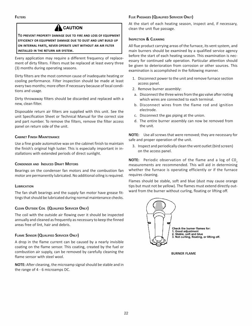
22
FILTERS
TO PREVENT PROPERTY DAMAGE DUE TO FIRE AND LOSS OF EQUIPMENT EFFICIENCY OR EQUIPMENT DAMAGE DUE TO DUST AND LINT BUILD UP ON INTERNAL PARTS, NEVER OPERATE UNIT WITHOUT AN AIR FILTER INSTALLED IN THE RETURN AIR SYSTEM.
CAUTION
Every application may require a different frequency of replace-ment of dirty filters. Filters must be replaced at least every three(3) months during operating seasons.
Dirty filters are the most common cause of inadequate heating orcooling performance. Filter inspection should be made at leastevery two months; more often if necessary because of local condi-tions and usage.
Dirty throwaway filters should be discarded and replaced with anew, clean filter.
Disposable return air filters are supplied with this unit. See theunit Specification Sheet or Technical Manual for the correct sizeand part number. To remove the filters, remove the filter accesspanel on return side of the unit.
CABINET FINISH MAINTENANCE
Use a fine grade automotive wax on the cabinet finish to maintainthe finish’s original high luster. This is especially important in in-stallations with extended periods of direct sunlight.
CONDENSER AND INDUCED DRAFT MOTORS
Bearings on the condenser fan motors and the combustion fanmotor are permanently lubricated. No additional oiling is required.
LUBRICATION
The fan shaft bearings and the supply fan motor have grease fit-tings that should be lubricated during normal maintenance checks.
CLEAN OUTSIDE COIL (QUALIFIED SERVICER ONLY)The coil with the outside air flowing over it should be inspectedannually and cleaned as frequently as necessary to keep the finnedareas free of lint, hair and debris.
FLAME SENSOR (QUALIFIED SERVICER ONLY)A drop in the flame current can be caused by a nearly invisiblecoating on the flame sensor. This coating, created by the fuel orcombustion air supply, can be removed by carefully cleaning theflame sensor with steel wool.
NOTE: After cleaning, the microamp signal should be stable and inthe range of 4 - 6 microamps DC.
FLUE PASSAGES (QUALIFIED SERVICER ONLY)At the start of each heating season, inspect and, if necessary,clean the unit flue passage.
INSPECTION & CLEANING
All flue product carrying areas of the furnace, its vent system, andmain burners should be examined by a qualified service agencybefore the start of each heating season. This examination is nec-essary for continued safe operation. Particular attention shouldbe given to deterioration from corrosion or other sources. Thisexamination is accomplished in the following manner.
1. Disconnect power to the unit and remove furnace sectionaccess panel.
2. Remove burner assembly:a. Disconnect the three wires from the gas valve after noting
which wires are connected to each terminal.b. Disconnect wires from the flame rod and ignition
electrode.c. Disconnect the gas piping at the union.d. The entire burner assembly can now be removed from
the unit.
NOTE: Use all screws that were removed; they are necessary forsafe and proper operation of the unit.
3. Inspect and periodically clean the vent outlet (bird screen)on the access panel.
NOTE: Periodic observation of the flame and a log of C02measurements are recommended. This will aid in determiningwhether the furnace is operating efficiently or if the furnacerequires cleaning.Flames should be stable, soft and blue (dust may cause orangetips but must not be yellow). The flames must extend directly out-ward from the burner without curling, floating or lifting off.
BURNER FLAME

23
TO AVOID PERSONAL INJURY OR DEATH DUE TO ELECTRIC SHOCK, DO NOT REMOVE ANY INTERNAL COMPARTMENT COVERS OR ATTEMPT ANY ADJUSTMENT. CONTACT A QUALIFIED SERVICER AT ONCE IF AN ABNORMAL FLAME SHOULD DEVELOP.
WARNING
At least once a year, prior to or during the heating season, make avisual check of the burner flames.
NOTE: This will involve removing and reinstalling the heatexchanger door on the unit, which is held by two screws. If you areuncertain about your ability to do this, contact a qualified servicer.If a strong wind is blowing, it may alter the airflow pattern withinthe unit enough that an inspection of the burner flames is notpossible.
FUNCTIONAL PARTS
Refer to the unit Parts Catalog for a list of functional parts. Partsare available from your distributor.
TROUBLESHOOTING
IGNITION CONTROL ERROR CODES
The following presents probable causes of questionable unit op-eration. Refer to Diagnostic Indicator Chart for an interpretationof the signal and to this section for an explanation.
Remove the control box access panel and note the number of di-agnostic LED flashes. Refer to Diagnostic Indicator Chart for aninterpretation of the signal and to this section for an explanation.
Internal Control Failure
If the integrated ignition control in this unit encounters an inter-nal fault, it will go into a “hard” lockout and turn off the diagnosticLED. If diagnostic LED indicates an internal fault, check power sup-ply to unit for proper voltage, check all fuses, circuit breakers andwiring. Disconnect electric power for five seconds. If LED remainsoff after restoring power, replace control.
ABNORMAL OPERATION - HEATING CODES
External Lockout (1 FLASH CODE)
An external lockout occurs if the integrated ignition control deter-mines that a measurable combustion cannot be established withinthree (3) consecutive ignition attempts. If flame is not establishedwithin the seven (7) second trial for ignition, the gas valve isdeenergized, 15 second inter-purge cycle is completed, and igni-tion is reattempted. The control will repeat this routine three timesif a measurable combustion is not established. The control willthen shut off the induced draft blower and go into a lockout state.
If flame is established but lost, the control will energize the circu-lator blower at the heat speed and then begin a new ignition se-quence. If flame is established then lost on subsequent attempts,the control will recycle for four (4) consecutive ignition attempts(five attempts total) before locking out.
The diagnostic fault code is 1 flash for a lockout due to failedignition attempts or flame dropouts. The integrated control willautomatically reset after one hour, or it can be reset by removingthe thermostat signal or disconnecting the electrical power sup-ply for over five seconds. If the diagnostic LED indicates an exter-nal lockout, perform the following checks:
• Check the supply and manifold pressures• Check the gas orifices for debris• Check gas valve for proper operation• Check secondary limit
A dirty filter, excessive duct static, insufficient air flow,a faulty limit, or a failed circulator blower can causethis limit to open. Check filters, total external ductstatic, circulator blower motor, blower motor speed tap(see wiring diagram), and limit. An interruption inelectrical power during a heating cycle may also causethe auxiliary limit to open. The automatic resetsecondary limit is located on top of the circulatorblower assembly.
• Check rollout limitIf the burner flames are not properly drawn into theheat exchanger, the flame rollout protection device willopen. Possible causes are restricted or blocked fluepassages, blocked or cracked heat exchanger, a failedinduced draft blower, or insufficient combustion air.The rollout protection device is a manual reset limitlocated on the burner bracket. The cause of the flamerollout must be determined and corrected beforeresetting the limit.
• Check flame sensorA drop in flame signal can be caused by nearly invisiblecoating on the sensor. Remove the sensor and carefullyclean with steel wool.
• Check wiringCheck wiring for opens/shorts and miswiring.
IMPORTANT: If you have to frequently reset your gas/electricpackage unit, it means that a problem exists that should becorrected. Contact a qualified servicer for further information.
Pressure Switch Stuck Open (2 FLASH CODE)
A pressure switch stuck open can be caused by a faulty pressureswitch, faulty wiring, a disconnected or damaged hose, a blockedor restricted flue, or a faulty induced draft blower.
If the control senses an open pressure switch during the pre-purgecycle, the induced draft blower only will be energized. If the pres-sure switch opens after ignition has begun the gas valve isdeenergized, the circulator blower heat off cycle begins, and theinduced draft blower remains on. The diagnostic fault code is twoflashes.
24
Pressure Switch Stuck Closed (3 FLASH CODE)
A stuck closed pressure switch can be caused by a faulty pres-sure switch or faulty wiring. If the control encounters a pressureswitch stuck closed, the induced draft blower remains off. Thediagnostic LED code for this fault is three (3) flashes.
Open Thermal Protection Device (4 FLASH CODE)
If the primary limit switch opens, the gas valve is immediatelydeenergized, the induced draft and air circulating blowers are en-ergized. The induced draft and air circulator blowers remain en-ergized until the limit switch recloses. The diagnostic fault codefor an open limit is four (4) flashes.
A primary limit will open due to excessive supply air tempera-tures. This can be caused by a dirty filter, excessive duct static,insufficient air flow, or a faulty limit. Check filters, total externalduct static, blower motor, blower motor speed tap (see wiringdiagram), and limit. This limit will automatically reset once thetemperature falls below a preset level.
Flame Detected with Gas Valve Closed (5 FLASH CODE)
If flame is detected with the gas valve deenergized, the combus-tion and air circulator blowers are energized. The diagnostic faultcode is five (5) flashes for this condition. The control can be resetby removing the power supply to the unit or it will automaticallyreset after one hour. Miswiring is the probable cause for this fault.
ABNORMAL OPERATION - COOLING CODES
Short Cycle Compressor Delay (6 FLASH CODE)
The automatic ignition control has a built-in feature that pre-vents damage to the compressor in short cycling situations. Inthe event of intermittent power losses or intermittent thermostatoperation, the ignition control will delay output to the compres-sor contactor for three minutes from the time power is restored.(Compressor is off a total of three minutes). The diagnostic LEDwill flash six (6) times to indicate the compressor contactor out-put is being delayed.
NOTE: Some electronic thermostats also have a built-incompressor short cycle timer that may be longer than the threeminute delay given above. If you are using an electronicthermostat and the compressor has not started after three minutes,wait an additional five minutes to allow the thermostat tocomplete its short cycle delay time.
TO PREVENT UNRELIABLE OPERATION OR EQUIPMENT DAMAGE, THE GAS MANIFOLD PRESSURE MUST BE AS SPECIFIED ON THE UNIT RATING PLATE. ONLY MINOR ADJUSTMENTS SHOULD BE MADE BY ADJUSTING THE GAS VALVE PRESSURE REGULATOR.
CAUTION

25
APPENDIX A BLOWER PERFORMANCE DATABELT DRIVE - STANDARD
NOTES:
High static airflow requires installation of high static kit.
Unit factory shipped with sheave set at 2.5 turns open.
Air flow tables represent dry coil with filters installed; SCFM correction factor for wet coil is 4%.
CFM BHP CFM BHP CFM BHP CFM BHP CFM BHP CFM BHP CFM BHP
0.2 --- --- --- --- --- --- --- 0.00 6827 2.67 6394 2.28 5982 1.94
0.4 --- --- --- --- 7079 3.20 6623 2.76 6161 2.34 5706 1.98 5271 1.66
0.6 --- --- 6903 3.32 6405 2.83 5923 2.41 5434 2.02 4949 1.68 --- ---
0.8 6717 3.42 6198 2.92 5668 2.45 5152 2.05 --- --- --- --- --- ---
1.0 5975 2.99 5418 2.51 --- --- --- --- --- --- --- --- --- ---
1.2 5147 2.55 --- --- --- --- --- --- --- --- --- --- --- ---
CFM BHP CFM BHP CFM BHP CFM BHP CFM BHP CFM BHP CFM BHP
0.2 --- --- --- --- 9359 4.92 8991 3.79 8621 3.54 8188 3.27 7826 3.040.4 --- --- 9018 3.18 8632 4.39 8251 3.39 7867 3.15 7363 2.85 6992 2.63
0.6 --- --- 8279 2.96 7879 3.86 7484 2.99 7085 2.75 --- --- --- ---
0.8 7957 4.82 7513 2.73 7097 3.35 --- --- --- --- --- --- --- ---
1.0 7179 4.23 6716 2.49 --- --- --- --- --- --- --- --- --- ---
1.2 6368 3.66 --- --- --- --- --- --- --- --- --- --- --- ---
DCG180 STANDARD BELT DRIVE (includes 2 speed models at high speed)
ESP, In H2OTURNS OPEN
0 1 2 3 4 5 6
DCG240 STANDARD BELT DRIVE (includes 2 speed models at high speed)
ESP, In H2O
TURNS OPEN
0 1 2 3 4 5 6
CFM BHP CFM BHP CFM BHP CFM BHP CFM BHP CFM BHP CFM BHP
0.2 9960 6.43 9464 5.80 8996 5.22 8553 4.67 8138 4.16 8005 4.00 7371 3.24
0.4 9324 6.07 8846 5.47 8396 4.91 7970 4.39 7570 3.90 7442 3.75 6831 3.02
0.6 8688 5.70 8229 5.13 7796 4.60 7386 4.10 7002 3.64 6879 3.49 --- ---
0.8 8052 5.34 7612 4.80 7196 4.29 6803 3.81 --- --- --- --- --- ---
1.0 7417 4.98 6994 4.46 6596 3.98 --- --- --- --- --- --- --- ---
1.2 6781 4.62 --- --- --- --- --- --- --- --- --- --- --- ---
DCG300 STANDARD BELT DRIVE (includes 2 speed models at high speed)
ESP, In H2O
TURNS OPEN
0 1 2 3 4 5 6

26
APPENDIX A BLOWER PERFORMANCE DATABELT DRIVE - HIGH STATIC
NOTES:
High static airflow requires installation of high static kit.
Unit factory shipped with sheave set at 2.5 turns open.
Air flow tables represent dry coil with filters installed; SCFM correction factor for wet coil is 4%.
CFM BHP CFM BHP CFM BHP CFM BHP CFM BHP CFM BHP CFM BHP1.0 --- --- --- --- --- --- --- --- 6690 3.69 6008 3.02 5321 2.431.2 --- --- --- --- --- --- 6653 3.95 5922 3.22 5182 2.58 --- ---1.4 --- --- --- --- 6634 2.80 5857 3.44 5056 2.74 --- --- --- ---1.6 --- --- 6638 4.55 5808 2.43 4948 2.91 --- --- --- --- --- ---1.8 6683 4.93 5784 3.95 4855 2.05 --- --- --- --- --- --- --- ---2.0 5803 4.27 4788 3.32 --- --- --- --- --- --- --- --- --- ---
CFM BHP CFM BHP CFM BHP CFM BHP CFM BHP CFM BHP CFM BHP1.0 --- --- --- --- --- --- 9001 6.83 8394 6.01 7797 4.78 7227 4.281.2 --- --- --- --- 8891 6.83 8262 6.15 7632 5.35 7012 4.20 --- ---1.4 --- --- 8811 6.86 8148 6.15 7495 5.48 6841 4.71 --- --- --- ---1.6 --- --- 8065 6.19 7377 5.18 --- --- --- --- --- --- --- ---1.8 7998 6.89 7290 5.52 --- --- --- --- --- --- --- --- --- ---2.0 7221 6.10 --- --- --- --- --- --- --- --- --- --- --- ---
CFM BHP CFM BHP CFM BHP CFM BHP CFM BHP CFM BHP CFM BHP0.4 --- --- --- --- --- --- --- --- --- --- 9854 6.74 9259 5.990.6 --- --- --- --- --- --- --- --- 9812 7.13 9197 6.35 8626 5.630.8 --- --- --- --- --- --- 9771 7.52 9131 6.70 8541 5.95 7993 5.271.0 --- --- --- --- --- --- 9063 7.05 8450 6.27 7885 5.56 7359 4.911.2 --- --- --- --- 8990 7.39 8355 6.58 7769 5.84 7228 5.17 6726 4.551.4 --- --- 8968 7.80 8253 6.88 7647 6.11 7088 5.41 6572 4.77 --- ---1.6 --- --- 8197 7.23 7516 6.37 6939 5.64 --- --- --- --- --- ---1.8 8136 7.58 7426 6.67 6779 5.85 --- --- --- --- --- --- --- ---2.0 7327 6.97 6654 6.11 --- --- --- --- --- --- --- --- --- ---2.2 6518 6.35 --- --- --- --- --- ---
DCG180 HIGH STATIC BELT DRIVE
ESP, In H2OTURNS OPEN
0 1 2 3 4 5 6
DCG240 HIGH STATIC BELT DRIVE
ESP, In H2OTURNS OPEN
0 1 2 3 4 5 6
DCG300 HIGH STATIC BELT DRIVE
ESP, In H2OTURNS OPEN
0 1 2 3 4 5 6

27
APPENDIX A ECONOMIZER PRESSURE DROP
SCFM 4500 5000 5500 6000 6500 7000 7500 8000 8500 9000 9500 10000
(In WG) 0.15 0.18 0.22 0.27 0.32 0.37 0.42 0.48 0.55 0.61 0.69 0.76
Airflow Pressure Drop of Downflow Economizer for 15 to 25 Ton Rooftop Units (100% Return Air)
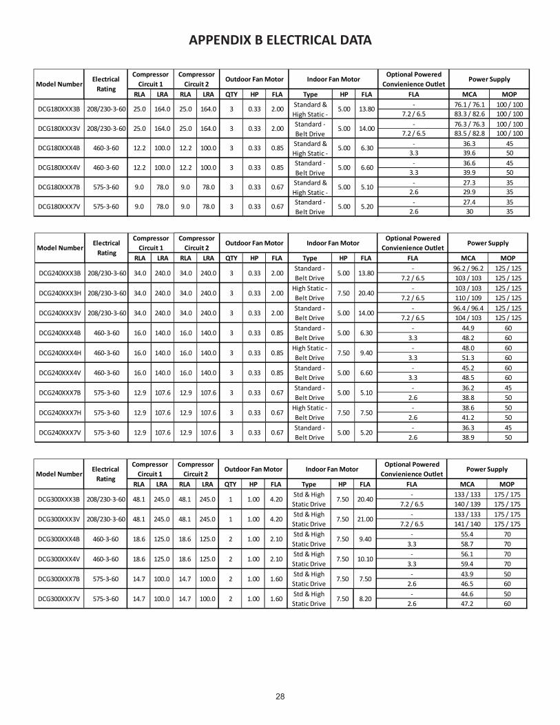
28
APPENDIX B ELECTRICAL DATA
RLA LRA RLA LRA QTY HP FLA Type HP FLA FLA MCA MOP- 76.1 / 76.1 100 / 100
7.2 / 6.5 83.3 / 82.6 100 / 100- 76.3 / 76.3 100 / 100
7.2 / 6.5 83.5 / 82.8 100 / 100- 36.3 45
3.3 39.6 50- 36.6 45
3.3 39.9 50- 27.3 35
2.6 29.9 35- 27.4 35
2.6 30 3578.0DCG180XXX7V 575-3-60 9.0 78.0 9.0
5.00 5.100.33
0.333 0.67 Standard - Belt Drive
5.00
DCG180XXX4B 460-3-60 12.2 100.0 12.2
5.20
DCG180XXX4V 3 0.85 Standard - Belt Drive
DCG180XXX7B 575-3-60 9.0 78.0 9.0
460-3-60 12.2
78.0 3 0.67 Standard & High Static -
100.0 12.2 100.0
3 0.85 Standard & High Static -
5.00 6.60
6.30100.0 0.33 5.00
0.33
2.00 Standard - Belt Drive
5.00DCG180XXX3V 208/230-3-60 25.0 164.0 25.0 14.000.33164.0 3
Power SupplyIndoor Fan MotorOptional Powered
Convienience OutletOutdoor Fan Motor
5.00 13.80DCG180XXX3B 208/230-3-60 25.0 164.0 25.0 164.0
Electrical Rating
0.33
Compressor Circuit 1
Compressor Circuit 2
3 2.00 Standard & High Static -
Model Number
RLA LRA RLA LRA QTY HP FLA Type HP FLA FLA MCA MOP- 96.2 / 96.2 125 / 125
7.2 / 6.5 103 / 103 125 / 125- 103 / 103 125 / 125
7.2 / 6.5 110 / 109 125 / 125- 96.4 / 96.4 125 / 125
7.2 / 6.5 104 / 103 125 / 125- 44.9 60
3.3 48.2 60- 48.0 60
3.3 51.3 60- 45.2 60
3.3 48.5 60- 36.2 45
2.6 38.8 50- 38.6 50
2.6 41.2 50- 36.3 45
2.6 38.9 50575-3-60 12.9 107.6 12.9 107.6
DCG240XXX7H 575-3-60 12.9 107.6 12.9
DCG240XXX4H
3 0.67Standard - Belt Drive
5.00 5.200.33
High Static - Belt Drive
7.50 7.500.333 0.67
Standard - Belt Drive
5.00 5.1012.9 107.6 12.9 107.6 3 0.670.33
DCG240XXX7V
DCG240XXX7B 575-3-60
107.6
6.60140.0
7.50 9.40
0.333 0.85Standard - Belt Drive
3 0.85High Static - Belt Drive
0.33460-3-60 16.0 140.0 16.0 140.0
DCG240XXX4V 460-3-60 16.0 140.0
240.0
5.00
34.0
High Static - Belt Drive
DCG240XXX3H 208/230-3-60 34.0 240.0 34.0 240.0 3
DCG240XXX3V 208/230-3-60 34.0 240.0
DCG240XXX4B 460-3-60 16.0 140.0 16.0 140.0 3 0.85
16.0
Compressor Circuit 1
Compressor Circuit 2
Electrical Rating
DCG240XXX3B 208/230-3-60 34.0 240.0 34.0 240.0
Model NumberOutdoor Fan Motor
Standard - Belt DriveStandard - Belt Drive
0.33
0.33
0.33
0.33
Optional Powered Convienience Outlet
Standard - Belt Drive
5.00 13.802.003
2.00
3 2.00
6.305.00
7.50 20.40
5.00 14.00
Power SupplyIndoor Fan Motor
RLA LRA RLA LRA QTY HP FLA Type HP FLA FLA MCA MOP- 133 / 133 175 / 175
7.2 / 6.5 140 / 139 175 / 175- 133 / 133 175 / 175
7.2 / 6.5 141 / 140 175 / 175- 55.4 70
3.3 58.7 70- 56.1 70
3.3 59.4 70- 43.9 50
2.6 46.5 60- 44.6 50
2.6 47.2 60DCG300XXX7V 575-3-60 14.7 100.0 14.7
Power SupplyOutdoor Fan Motor Indoor Fan Motor
2 2.10Std & High Static Drive
7.50
7.50
9.40
21.00
Optional Powered Convienience Outlet
1.00
Std & High Static Drive
1
10.10
1.60Std & High Static Drive
7.50
7.50
7.50Std & High Static Drive
8.20
2.10Std & High Static Drive
7.50
1.60DCG300XXX7B 575-3-60 14.7 100.0 14.7
DCG300XXX4V 460-3-60 18.6 125.0 18.6
Electrical Rating
Model Number
Std & High Static Drive
7.50 20.4048.1 245.0DCG300XXX3B 208/230-3-60 48.1 245.0 4.20
245.0 1 4.20DCG300XXX3V 208/230-3-60 245.0 48.148.1
DCG300XXX4B 460-3-60 125.0
1.00
1.00
1.00
Compressor Circuit 1
Compressor Circuit 2
100.0
100.0
125.0 2
2
2
1.00
1.00
18.6 125.018.6

29
APPENDIX C UNIT DIMENSIONS
VERTICAL DISCHARGE (TOP VIEW)
21” 60”
7”
48”
22”
B
C
D
A
Model A B C D
15 Ton20 Ton
133-1/2" 88-7/32" 50-9/32" 5-5/32"
25 Ton 133-1/2" 88-7/32" 53-9/32" 5-5/32"
NOTE: 15 & 20 ton models have 3 fans.25 ton models have 2 fans.

30
APPENDIX D WIRING DIAGRAMS

31
HIG
H V
OLT
AG
E!
DIS
CO
NN
ECT
ALL
PO
WE
R B
EFO
RE
SER
VIC
ING
OR
INS
TALL
ING
TH
ISU
NIT
. M
ULT
IPLE
PO
WER
SO
UR
CES
MAY
BE
PR
ESEN
T. F
AIL
UR
E TO
DO
SO
MAY
CA
US
E PR
OP
ERTY
DA
MA
GE,
PER
SON
AL
INJU
RY
OR
DE
ATH
.
Wiring is subject to change. Always refer to the wiring diagram on the unit for the most up-to-date wiring.
DCG180* / DCG240* 208-230 / 3 / 60 1 SPEED
2
CC
T2BC
EM
COMP
2
CM3
CM1
CM2
FC2
FC3
TB2
F
C
F
C
F
VM
123
24V
L2
UNUSED
COOL HEAT
L1
456
23
8 97
LS
3
2
1
9 6
8
7 4
5
GV
ALS
PS
RS
GRND
LPS1
RD
YL
RD
RD
BK
PU
YL
PU
PU
BL
BL
3
1
VMR
4
6
42
1 6
YL
BL
CCH1
CCHR2
PU
BK
RD
OR
CC
2
T2T1
1
L2L1
T3
L3
T2T1
L2L1
T3
L3
T1BC
L2L1
T3
L3
T1
T2
T3
T1
T2
T3
EM
COMP
2
COMP
1
CM3
CM1
CM2
FC1
FC2
FC3
TB2
F
F
C
F
C
VM
123
24V
L2
UNUSED
COOL HEAT
DI
FS
L1
456
23 1
11
8
12
9
10
IIC
LS
3
2
1
9 6
8
7 4
5
GV
ALS
PS
RS
GRND
FS
IGN
LPS1
LPS2
HPS1
HPS2
RD WH
BK
BK
RD
RD
BK
BK OR
RD YLBK RDBK
RD
YL
BK
RD
YL
BK
RDRD
BK
BK
BK
BK
PU
PU
PU
PU
PU PU
PU
PU
BR BR
BR
BR
BR
BR
BR
BR
RD
RD
WH
WHWH
OR
BK
RD
OR
BL
BL
BL
BL
BL
BL
BL
BL
BL
BL
YL
YL
YL
YL
GR
GR
GR
GR
GR
GR
YL
YL
YL
BL
BL YL
PU
WH
WH
YL
YL
YL
YL
YL
YL
GR
GR
BK
PU
PU
PU
BL
BL
BL
BL
BL
BL
BL
BL
YL
YL
YL
WH
WH
WH
GR
GR
GR
RD
RD
RD
BR
BR
BLBL
BL
PU
PU
PU PU PU PU
PU
GRBL
BL
BL
PK
BR
BR
BR
YL
YL
YL
YL
YL
YL RD
RD
RD
BL
BL
BL
WH
WH
WH
WH
OR
OR
3
1
VMR
4
6 BK
BK
RD
OR
RD
BK
PB
BKRD
OR
42
CCHR1
BK
CCH2
PU
BK
BK
BL
BL
OR
BK42
1 6
42
SEEN
OTE 2
PLF
OR
PU
YL
0140L02579-A
BL
322222224
1
23
22 2222241
2
YL
BL
RD
YL
YL
PU
BL
YL
CCR2
CCR1
RD
GR
R
REP
LACE JU
MPE
RW
ITHS
MO
KE/FIR
ED
ETEC
TOR
C Y1 Y2S2 G
WH
SE
E N
OTE
5
S1
RD
W1 W2 O
YL
POWER SUPPLYSEE NOTE 4
208V / 240V - 3 ph - 60Hz
BK
BK
230 208 C
BR
PK
PK
PK
PK
PK
SEE NOTE 7
TO THERMOSTAT
R
R
WIRING DIAGRAMS

32
HIG
H V
OLT
AG
E!
DIS
CO
NN
ECT
ALL
PO
WE
R B
EFO
RE
SER
VIC
ING
OR
INS
TALL
ING
TH
ISU
NIT
. M
ULT
IPLE
PO
WER
SO
UR
CES
MAY
BE
PR
ESEN
T. F
AIL
UR
E TO
DO
SO
MAY
CA
US
E PR
OP
ERTY
DA
MA
GE,
PER
SON
AL
INJU
RY
OR
DE
ATH
.
Wiring is subject to change. Always refer to the wiring diagram on the unit for the most up-to-date wiring.
DCG180* / DCG240* 208-230/ 3 / 60 1 SPEED
2
1
W1 TO W2 WIRE JUMPER.
5. FOR TWO STAGE OPERATION REMOVE
FALSE FLAME SENSED
OPEN LIMIT SWITCH
WITHOUT INDUCER ON
PRESSURE SWITCH CLOSED
OPEN
PRESSURE SWITCH
NORMAL OPERATION
3 BLINKS
6 BLINKS
4 BLINKS
5 BLINKS
OUTPUT DELAY
COMPRESSOR
OFF
ON
1 BLINK
2 BLINKS
STATUS LIGHT
SWITCH
OPEN AUX. LIMIT
IGNITION FAILURE
SWITCH
OPEN ROLLOUT
INTERNAL CONTROL
NO POWER OR
EQUIPMENT STATUS
PRESSURE SWITCH
CHECK
BAD SWITCH
MAIN LIMIT OPEN
STICKING GAS VALVE
ANTI-CYCLE TIMER
3 MIN. COMP.
PRESSURE SWITCH
CHECK
GAS PRESSURE
FLAME ROLLOUT
AUX. LIMIT OPEN
FLAME SENSOR
BAD SWITCH
GAS VALVE
GAS FLOW
REPLAC E CONTROL
CHECK FUSE ON CONTROL
CHECK INPUT POWER
------
CHECK
HPS2LPS2
IIC
9
11
12
8
6
3
ECON
10
PS
ALS
L1
4
5
F
RS
L2NOTE 3
IIC
5
47
8
69
1
2
3
TR
24V
PLFSEENOTE 2
SUPPLY VOLTAGE208-240/3/60
L2
13
1 3
CC1
T3
COMP1
T2
F
CM1
EM
T1
C
T2
VM
VENT MOTOR RELAY
VENT MOTOR
TRANSFORMER
TERMINAL BLOCK (24V SIGNAL)
ROLLOUT SWITCH
PRESSURE SWITCH
FEMALE PLUG/CONNECTOR
LIMIT SWITCH
LOW PRESSURE SWITCH
IGNITOR
INTEGRATED IGNITION CONTROL
INDOOR BLOWER RELAY
HIGH PRESSURE SWITCH
GAS VALVE
EQUIPMENT GROUND
FLAME SENSOR
FAN CAPACITOR
FUSE
EVAPORATOR MOTOR
COMPRESSOR CONTACTOR
CONDENSER MOTOR
COMPRESSOR
BLOWER CONTACTOR
AUXILLARY LIMIT SWITCH
VM
TR
TB1
RS
PS
PLF
LS
LPS
IGN
IIC
IBR
HPS
GV
GND
FS
FC
F
EM
CC
CM
COMP
BC
ALS
NOTES
2
(USE COPPER CONDUCTOR ONLY).
SIZE AND TYPE OF INSULATION AS ORIGINAL.
1. REPLACEMENT WIRE MUST BE THE SAME
3
ACCESSORY.
ATTACH FEMALE PLUG TO THE ECONOMIZER
COMPARTMENT. REMOVE MALE PLUG AND
TO BLOWER HOUSING IN RETURN AIR
2. ACCESSORY ECONOMIZER PLUG ADJACENT
4. USE COPPER CONDUCTORS ONLY.
USE NEC CLASS 2 WIRE.
4
3. L1 AND L2 ON IIC CONTROL IS 24V INPUT.
0140L02580-A
COMPONENT LEGEND
T1
TERMINAL BLOCK (L1)TB2
2
FROM TERMINAL 3 TO TERMINAL 2 ON THE TRANSFORMER.
6. FOR 208V OPERATION MOVE BLACK WIRE
OF OVER CURRENT PROTECTION
SEE UNIT RATING PLATE FOR TYPE AND SIZE
PB POWER DISTRUBTION BLOCK
CRANK CASE HEATERCCH
CRANK CASE HEATER RELAYCCHR
2 1
1
CCH1
CCH2
CCHR1
C
CM2
FFC2
7. IF DDC CONTROL OPTON IS INSTALLED,THERMOSTAT FIELD WIRING IS NOT REQUIRED.SEE DDC CONTROL WIRING DIAGRAM ANDINSTRUCTIONS.
CCR COMPRESSOR CONTACTOR RELAY
BC
T2CC2
T1CC2
T2COMP2
T3
CC2
T2 BC
T1
T3
FACTORY WIRING
THERMOSTAT
FIELD WIRING
HIGH VOLTAGE
LOW VOLTAGE
FIELD WIRING
LINE VOLTAGE
LOW VOLTAGE
HIGH VOLTAGE
WIRE CODE
BK BLACK
BL BLUE
BR BROWN
GR GREEN
OR ORANGE
PK PINK
PU PURPLE
RD RED
WH WHITE
YL YELLOW
YL/PK YELLOW WITH
PINK STRIP
BL/PK BLUE WITH
PINK STRIP
Y1
TB1
W
G
W
PK
RD
Y1
R
OR
BL
GR
C
2 STAGE COOLING
WH
O
STAT
O
Y2
C
G
R
YL
W1 TO W2 WIRE JUMPER.
5. FOR TWO STAGE OPERATION REMOVE
INSTALLER/SERVICEMAN
TROUBLESHOOTING THIS APPLIANCE. STATUS LIGHT CODES ARE AS FOLLOWS:THE STATUS LIGHT ON THE FURNACE CONTROL MAY BE USED AS A GUIDE TO
CCR2
7
NOTE 3
FS
GV
CCR1
IGN
FS
TB1
L1 L3
FC1
F
CC1
C
CC1
NOTES
2
(USE COPPER CONDUCTOR ONLY).
SIZE AND TYPE OF INSULATION AS ORIGINAL.
1. REPLACEMENT WIRE MUST BE THE SAME
3
ACCESSORY.
ATTACH FEMALE PLUG TO THE ECONOMIZER
COMPARTMENT. REMOVE MALE PLUG AND
TO BLOWER HOUSING IN RETURN AIR
2. ACCESSORY ECONOMIZER PLUG ADJACENT
4. USE COPPER CONDUCTORS ONLY.
USE NEC CLASS 2 WIRE.
4
3. L1 AND L2 ON IIC CONTROL IS 24V INPUT.
T3
208-240v
FROM TERMINAL 3 TO TERMINAL 2 ON THE TRANSFORMER.
6. FOR 208V OPERATION MOVE BLACK WIRE
2
CCHR2
6 6 44
7. IF DDC CONTROL OPTON IS INSTALLED,THERMOSTAT FIELD WIRING IS NOT REQUIRED.SEE DDC CONTROL WIRING DIAGRAM ANDINSTRUCTIONS.
SEE NOTE 7
T3
T1
Y1
TB1
W
G
PK
RD
OR
BL
GR
WH
O
STAT
Y2
C
R
YL
CH BC
24
24
HPS1LPS1
D1
VMR
46
CC1
CC2CCR2
CCR1
FC3
F
CM3
C
R C
WH
G OW1 Y2S1
RD
S2 W2 Y1
NOTE 5
BC
LS
Y2TO THERMOSTATOPTIONAL
VMR
WIRING DIAGRAMS

33
DCG180*/ DCG240* 460, 575/ 3 / 60 1 SPEEDH
IGH
VO
LTA
GE
!D
ISC
ON
NEC
T A
LL P
OW
ER
BEF
OR
E S
ERVI
CIN
G O
R IN
STA
LLIN
G T
HIS
UN
IT.
MU
LTIP
LE P
OW
ER S
OU
RC
ES M
AY B
E P
RES
ENT.
FA
ILU
RE
TOD
O S
O M
AY C
AU
SE
PRO
PER
TY D
AM
AG
E, P
ERSO
NA
L IN
JUR
Y O
R D
EAT
H.
Wiring is subject to change. Always refer to the wiring diagram on the unit for the most up-to-date wiring.
T2 T1
CC2
L2 L1
T3T2 T1
CC1
L2 L1
T3
L3 L3
T2 T1
BC
L2 L1
T3
L3
T1
T2
T3
T1
T2
T3
EM
COMP2
COMP1
VM
3 2 1
24V
3
1
L2
UNUSED
COOLHEAT
DIL1
4 5 6
2 31
ECON
11
8
12
97
10
3
2
1
96
8
74
5
GV
ALS
PS
RS
GND
LPS1
LPS2
HPS1
HPS2
VMR
++
RDWH
BK BK
RD
RD
BK
BKOR
RDYL BKRDYL BK
RD
YL
BK
RD
YL
BK
RD
RDBK
RD
BK
WH
WH WH
BK
OR
RDRD
BK
BL
BL
BL
BL
BL
BL
BL
YL
YL
YL
PU
PU
GR
GR
GR
GR
GR
GR
YL
BL
BLYL
PU
WH
WH
YL
YL
YL
YL
YL
GR
GR
BK
PU
PU
BL
BL
BLBL
BL
BL
BL
BL
BL
YL
YL
WH
WH
GR
RD
RD
BR
BR
BL BL
BL
PU
PUPUPUPU
PU
GR BL
BL
BL
PK
BRBR
BR
YL
YL
YL
YL
YL
YL
RD
BL
BL
BL
BL
WH
WH
WH
WH
4
6
2
1
4
6
2
1
4
6
CCHR1
BL
YL
BK
CCH1
CCH2
PU
BK
BK
OR
CCHR2
BL
BK
BL
OR
RD
PU
BK
BK
BK
0140
L025
83-A
TOTHERMOSTAT
ORAPPROPRIATE
460C
INPUTVOLTAGE
240
IIC
RD
SEE
NO
TE6
BK
BL
BL
GR
RD
RD
RD
LS
FS
POWERSUPPLY
SEENOTE4
460V/575-3ph-60
Hz
BL
OROR
RD
BK
WH
GR
OR
RD
IGN
FS
NOTE2PLF
SEE
460
BK
BK
BK
RD
RD
BR
BR
BR
PU
PU
PU
BK
BKBK
RD
C
F
C
F
TB2
FC3
FC2
CM2
CM1
CM3
BK
C
F
FC1
BR
BR
BR BR
BR
PU
PU
PU
PU PU
YL
YL
YL
YL
YL
YL
PU
BL
NOTE6
3
1
2
4
3
1
2
4
PU
R
REP
LAC
E JU
MPE
RW
ITH
SMO
KE/
FIR
E D
ETEC
TOR
CY1Y2 S2G
WH
SEE
NO
TE5
S1
RD
W1W2O TB1
PU YL
YL
BR
PK
PK
PK
PK
WH RDGR R
R
WIRING DIAGRAMS

34
HIG
H V
OLT
AG
E!
DIS
CO
NN
ECT
ALL
PO
WE
R B
EFO
RE
SER
VIC
ING
OR
INS
TALL
ING
TH
ISU
NIT
. M
ULT
IPLE
PO
WER
SO
UR
CES
MAY
BE
PR
ESEN
T. F
AIL
UR
E TO
DO
SO
MAY
CA
US
E PR
OP
ERTY
DA
MA
GE,
PER
SON
AL
INJU
RY
OR
DE
ATH
.
Wiring is subject to change. Always refer to the wiring diagram on the unit for the most up-to-date wiring.
DCG180* / DCG240* 460, 575/ 3 / 60 1 SPEEDWIRING DIAGRAMS

35
CM3
CM1
CM2
FC2
FC3
TB2
F
C
F
C
F
L2
UNUSED
COOL HEAT
L1
456
23
8 97
LS
PS
GRND
PU
BL
CM3
CM1
CM2
FC1
FC2
FC3
TB2
F
F
C
F
C
L2
UNUSED
COOL HEAT
DI
FS
L1
456
23 1
11
8
12
9
10
IIC
LS
PS
GRND
FS
IGN
RD
BK
BK
BK
PU
PU
PU
PU
PU
PU
PU
PU
BR BR
BR
BR
BR
BR
BR
BR
RD
RD
RD
OR
GR
YL
YL
YL
PU
BL
BL
BL YL
WH
WH
WH
GR
GR
GR
RD
RD
RD
BR
BL
GR
BR
BR
BR
YL
YL
RD
RD
RD
BK
BK
PB
0140L03766-A
32
22
22
224
1
23
22
22
22
241
2
BL
BL
YL
CCR2
CCR1
RD
R C Y1 Y2S2 G
WH
SE
E N
OT
E 5
S1
RD
W1 W2 O
YL
POWER SUPPLY
SEE NOTE 4
208V / 240V - 3 ph - 60Hz
SEE NOTE 7
TO THERMOSTAT
LOW
SPEED
CB2
L2
T3
L1
T2
L3
T1
HIGH
SPEED
CB1
L2
T3
L1
T2
L3
T1
OR
RD
BK
GY
BL
YL YL
BL
GY
BK
RD
OR
L3T3
L2
CC1
L1T1
T2
L3T3
L2
CC2
L1T1
T2
L3T3
L2
BC1
L1T1
T2
L3T3
L2
BC2
L1T1
T2
T3
T2
T1
COMP
1
RD
YL
BK
CCH1
T3
T2
T1
COMP
2
RD
YL
BK
CCH2
C
TR
24V
240
4 2
16
CCHR2
4 2
CCHR1
4 2
16
4 2
YL
YL
HP
S2
LP
S2
BL
YL
YL
HP
S1
LP
S1
BL
GR
PU
BL
YL
YL
NO
NC
4
12
35
NO
NC
4
12
35
BR
2
BR
1G
R
GR
GR
YL
BL
WH
GR
GR
GR
GR
WH
YL
WH
GR
BL
BL
BL
BL
RE
PL
AC
E J
UM
PE
RW
ITH
SM
OK
E/F
IRE
DE
TE
CT
OR
PK
PK
GV
ALS
RS
BRBL
PU
PU
PU
OR
RD
RD
BK
WH
WH
BK
BK
RD
RD
BK
RD
OR
OR
OR
OR
OR
OR
RD
BK
RD
RD
RD
BK
BK
BK
BK
BK
BK
BK
BK
PU
RD
RD
YL
YL
YL
BL
BL
YL
YL
YL
PU
PU
PU
PU
YL
96
3
85
2
74
1WH
YL
YL
PU
BL
BL
BK
OR
BK BK
MVMV
WH
6
4
VMR
1
3
6
4
VMR
1
3
WH
PK
BL
BL
OR
WH
HIGH
EM
LOW
YL
YL
YL
BK
BK
BK
12
13
11
2
3
1
PU
PU
YL
RD
OR
BK
RD
OR
BK
OR
OR
SE
E N
OT
E 6
1 32
208
PLF2
PL
F 1
RD
RD
BL
BL
WH
BL
PU
BL
OR
RDBK
SEE NO
TE 2
BRRD
WH
WH
PK
WH
GR
GR
HIG
H V
OLT
AG
E!
DIS
CO
NN
ECT
ALL
PO
WE
R B
EFO
RE
SER
VIC
ING
OR
INS
TALL
ING
TH
ISU
NIT
. M
ULT
IPLE
PO
WER
SO
UR
CES
MAY
BE
PR
ESEN
T. F
AIL
UR
E TO
DO
SO
MAY
CA
US
E PR
OP
ERTY
DA
MA
GE,
PER
SON
AL
INJU
RY
OR
DE
ATH
.
Wiring is subject to change. Always refer to the wiring diagram on the unit for the most up-to-date wiring.
DCG180*/ DCG240* 208-230/ 3 / 60 2 SPEEDWIRING DIAGRAMS

36
HIG
H V
OLT
AG
E!
DIS
CO
NN
ECT
ALL
PO
WE
R B
EFO
RE
SER
VIC
ING
OR
INS
TALL
ING
TH
ISU
NIT
. M
ULT
IPLE
PO
WER
SO
UR
CES
MAY
BE
PR
ESEN
T. F
AIL
UR
E TO
DO
SO
MAY
CA
US
E PR
OP
ERTY
DA
MA
GE,
PER
SON
AL
INJU
RY
OR
DE
ATH
.
Wiring is subject to change. Always refer to the wiring diagram on the unit for the most up-to-date wiring.
DCG180*/ DCG240* 208-230/ 3 / 60 2 SPEED
2
1
W1 TO W2 WIRE JUMPER.
5. FOR TWO STAGE OPERATION REMOVE
FALSE FLAME SENSED
OPEN LIMIT SWITCH
WITHOUT INDUCER ON
PRESSURE SWITCH CLOSED
OPEN
PRESSURE SWITCH
NORMAL OPERATION
3 BLINKS
6 BLINKS
4 BLINKS
5 BLINKS
OUTPUT DELAY
COMPRESSOR
OFF
ON
1 BLINK
2 BLINKS
STATUS LIGHT
SWITCH
OPEN AUX. LIMIT
IGNITION FAILURE
SWITCH
OPEN ROLLOUT
INTERNAL CONTROL
NO POWER OR
EQUIPMENT STATUS
PRESSURE SWITCH
CHECK
BAD SWITCH
MAIN LIMIT OPEN
STICKING GAS VALVE
ANTI-CYCLE TIMER
3 MIN. COMP.
PRESSURE SWITCH
CHECK
GAS PRESSURE
FLAME ROLLOUT
AUX. LIMIT OPEN
FLAME SENSOR
BAD SWITCH
GAS VALVE
GAS FLOW
REPLACE CONTROL
CHECK FUSE ON CONTROL
CHECK INPUT POWER
------
CHECK
HPS2 LPS2
IIC
9
11
12
8
6
3
ECON
10
PS
ALS
L1
4
5
F
RS
L2
5
47
8
69
1
2
3
TR
24V
SUPPLY VOLTAGE
208-240/3/60L2
13
1 3
CC1
T3
COMP1
T2
F
CM1
T1
C
T2
VM
VENT MOTOR RELAY
VENT MOTOR
TRANSFORMER
TERMINAL BLOCK (24V SIGNAL)
ROLLOUT SWITCH
PRESSURE SWITCH
FEMALE PLUG/CONNECTOR
LIMIT SWITCH
LOW PRESSURE SWITCH
IGNITOR
INTEGRATED IGNITION CONTROL
INDOOR BLOWER RELAY
HIGH PRESSURE SWITCH
GAS VALVE
EQUIPMENT GROUND
FLAME SENSOR
FAN CAPACITOR
FUSE
EVAPORATOR MOTOR
COMPRESSOR CONTACTOR
CONDENSER MOTOR
COMPRESSOR
BLOWER CONTACTOR
AUXILLARY LIMIT SWITCH
VM
TR
TB1
RS
PS
PLF
LS
LPS
IGN
IIC
IBR
HPS
GV
GND
FS
FC
F
EM
CC
CM
COMP
BC
ALS
NOTES
2
(USE COPPER CONDUCTOR ONLY).
SIZE AND TYPE OF INSULATION AS ORIGINAL.
1. REPLACEMENT WIRE MUST BE THE SAME
3
ACCESSORY.
ATTACH FEMALE PLUG TO THE ECONOMIZER
COMPARTMENT. REMOVE MALE PLUG AND
TO BLOWER HOUSING IN RETURN AIR
2. ACCESSORY ECONOMIZER PLUG ADJACENT
4. USE COPPER CONDUCTORS ONLY.
USE NEC CLASS 2 WIRE.
4
3. L1 AND L2 ON IIC CONTROL IS 24V INPUT.
0140L03767-A
COMPONENT LEGEND
T1
TERMINAL BLOCK (L1)TB2
2
FROM TERMINAL 3 TO TERMINAL 2 ON THE TRANSFORMER.
6. FOR 208V OPERATION MOVE BLACK WIRE
OF OVER CURRENT PROTECTION
SEE UNIT RATING PLATE FOR TYPE AND SIZE
PB POWER DISTRUBTION BLOCK
CRANK CASE HEATERCCH
CRANK CASE HEATER RELAYCCHR
2 1
1
CCH1
CCH2
C
CM2
FFC2
CCR COMPRESSOR CONTACTOR RELAY
T2
CC2
T1
CC2
T2COMP2
T3
CC2
FACTORY WIRING
THERMOSTAT
FIELD WIRING
HIGH VOLTAGE
LOW VOLTAGE
FIELD WIRING
LINE VOLTAGE
LOW VOLTAGE
HIGH VOLTAGE
WIRE CODE
BK BLACK
BL BLUE
BR BROWN
GR GREEN
OR ORANGE
PK PINK
PU PURPLE
RD RED
WH WHITE
YL YELLOW
YL/PK YELLOW WITH
PINK STRIP
BL/PK BLUE WITH
PINK STRIP
Y1
TB1
W
G
W
PK
RD
Y1
R
OR
BL
GR
C
2 STAGE COOLING
WH
O
STAT
O
Y2
C
G
R
YL
W1 TO W2 WIRE JUMPER.
5. FOR TWO STAGE OPERATION REMOVE
INSTALLER/SERVICEMAN
TROUBLESHOOTING THIS APPLIANCE. STATUS LIGHT CODES ARE AS FOLLOWS:
THE STATUS LIGHT ON THE FURNACE CONTROL MAY BE USED AS A GUIDE TO
CCR2
7
NOTE 3
FS
GV
CCR1
IGN
FS
TB1
L1 L3
FC1
F
CC1
C
CC1
NOTES
2
(USE COPPER CONDUCTOR ONLY).
SIZE AND TYPE OF INSULATION AS ORIGINAL.
1. REPLACEMENT WIRE MUST BE THE SAME
3
ACCESSORY.
ATTACH FEMALE PLUG TO THE ECONOMIZER
COMPARTMENT. REMOVE MALE PLUG AND
TO BLOWER HOUSING IN RETURN AIR
2. ACCESSORY ECONOMIZER PLUG ADJACENT
4. USE COPPER CONDUCTORS ONLY.
USE NEC CLASS 2 WIRE.
4
3. L1 AND L2 ON IIC CONTROL IS 24V INPUT.
T3
208-240v
FROM TERMINAL 3 TO TERMINAL 2 ON THE TRANSFORMER.
6. FOR 208V OPERATION MOVE BLACK WIRE
2
CCHR2
6 4
SEE NOTE 7
T3
T1
Y1
TB1
W
G
PK
RD
OR
BL
GR
WH
O
STAT
Y2
C
R
YL
CH
24
24
HPS1 LPS1
D1
VMR
46
CC1
CC2CCR2
CCR1
FC3
F
CM3
C
R C
WH
G OW1 Y2S1
RD
S2 W2 Y1
NOTE 5
LS
Y2
TO THERMOSTAT
OPTIONAL
VMR
BLOWER RELAYBR
CCHR1
CCHR2
CIRCUIT BREAKERCB
EM
HIGH SPEED
LOW SPEED BC2CB2
CB1BC1
CB2BC2
BC2CB2
BC1CB1
BC1CB1
BC1
BC2
2
5
4
BR1
BR1
BR2
2
5
4
BR2
VMR
1 3
1 3
1 3
1 3
SEE
NOTE 2
CCHR16 4
WIRING DIAGRAMS

37
HIG
H V
OLT
AG
E!
DIS
CO
NN
ECT
ALL
PO
WE
R B
EFO
RE
SER
VIC
ING
OR
INS
TALL
ING
TH
ISU
NIT
. M
ULT
IPLE
PO
WER
SO
UR
CES
MAY
BE
PR
ESEN
T. F
AIL
UR
E TO
DO
SO
MAY
CA
US
E PR
OP
ERTY
DA
MA
GE,
PER
SON
AL
INJU
RY
OR
DE
ATH
.
Wiring is subject to change. Always refer to the wiring diagram on the unit for the most up-to-date wiring.
DCG180*/ DCG240* 460, 575/ 3 / 60 2 SPEED
CM3
CM1
CM2
FC2
FC3
TB2
F
C
F
C
F
L2
UNUSED
COOL HEAT
L1
456
23
8 97
LS
PS
GRND
PU
BL
CM3
CM1
CM2
FC1
FC2
FC3
TB2
F
F
C
F
C
L2
UNUSED
COOL HEAT
DI
FS
L1
456
23 1
11
8
12
9
10
IIC
LS
PS
GRND
FS
IGN
RD
BK
BK
BK
PU
PU
PU
PU
PU
PU
PU
PU
BR BR
BR
BR
BR
BR
BR
BR
RD
RD
RD
OR
GR
YL
YL
YL
PU
BL
BL
BL
BL YL
WH
WH
WH
GR
GR
GR
RD
RD
RD
BR
BL
GR
BR
BR
BR
YL
YL
RD
RD
RD
BK
BK
PB
0140L03768-A
32
22
22
224
1
23
22
22
22
241
2
BL
BL
YL
CCR2
CCR1
RD
R C Y1 Y2S2 G
WH
SE
E N
OT
E 5
S1
RD
W1 W2 O
YL
POWER SUPPLY
SEE NOTE 4
460V / 575V - 3 ph - 60Hz
SEE NOTE 7
TO THERMOSTAT
LOW
SPEED
CB2
L2
T3
L1
T2
L3
T1
HIGHSPEED
CB1
L2
T3
L1
T2
L3
T1
OR
RD
BK
GY
BL
YL YL
BL
GY
BK
RD
OR
L3T3
L2
CC1
L1T1
T2
L3T3
L2
CC2
L1T1
T2
L3T3
L2
BC1
L1T1
T2
L3T3
L2
BC2
L1T1
T2
T3
T2
T1
COMP
1
RD
YL
BK
CCH1
T3
T2
T1
COMP
2
RD
YL
BK
CCH2
C
TR
24V
4 2
16
4 2
4 2
16
4 2
YL
BL
YL
BL
PU
BL
YL
YL
NO
NC
4
12
35
NO
NC
4
12
35
BR
2
BR
1G
R
GR
GR
YL
BL
WH
GR
GR
GR
GR
WH
YL
WH
GR
BL
BL
BL
BL
RE
PLA
CE
JU
MP
ER
WIT
H S
MO
KE
/FIR
ED
ET
EC
TO
RP
K
PK
GV
ALS
RS
BRBL
PU
PU
PU
OR
RD
RD
BK
WH
WH
BK
BK
RD
RD
BK
RD
OR
OR
OR
OR
OR
OR
RD
BK
RD
RD
RD
BK
BK
BK
BK
BK
BK
BK
BK
PU
RD
RD
YL
YL
YL
YL
PU
PU
YL
96
3
85
2
74
1WH
YL
YL
PU
BL
BL RD
BK
OR
BK BK
MVMV
WH
6
4
VMR
1
3
6
4
VMR
1
3
WH
PK
OR APPROPRIATE
INPUT VOLTAGE
240
460
RD
RD
WH
HIGH
EMLOW
YL
YL
YL
BK
BK
BK
12
13
11
2
3
1
PU
PU
YL
RD
OR
BK
RD
OR
BK
460
575 SE
E N
OT
E 6
1 2
PLF2
YL
HP
S2
LP
S2
YL
HP
S1
LP
S1
BK
OR
BL
BL
BL
PL
F 1
WH
BL
PU
BL
OR
RDBK
SEE NO
TE 2
CCHR2
CCHR1
YL
YL
PU
PU
BL
BL
BL
BRRD
RD
GR
WH
WH
WH
PK
GR
GR
WIRING DIAGRAMS

38
HIG
H V
OLT
AG
E!
DIS
CO
NN
ECT
ALL
PO
WE
R B
EFO
RE
SER
VIC
ING
OR
INS
TALL
ING
TH
ISU
NIT
. M
ULT
IPLE
PO
WER
SO
UR
CES
MAY
BE
PR
ESEN
T. F
AIL
UR
E TO
DO
SO
MAY
CA
US
E PR
OP
ERTY
DA
MA
GE,
PER
SON
AL
INJU
RY
OR
DE
ATH
.
Wiring is subject to change. Always refer to the wiring diagram on the unit for the most up-to-date wiring.
DCG180* / DCG240* 460, 575/ 3 / 60 2 SPEEDWIRING DIAGRAMS

39
HIG
H V
OLT
AG
E!
DIS
CO
NN
ECT
ALL
PO
WE
R B
EFO
RE
SER
VIC
ING
OR
INS
TALL
ING
TH
ISU
NIT
. M
ULT
IPLE
PO
WER
SO
UR
CES
MAY
BE
PR
ESEN
T. F
AIL
UR
E TO
DO
SO
MAY
CA
US
E PR
OP
ERTY
DA
MA
GE,
PER
SON
AL
INJU
RY
OR
DE
ATH
.
Wiring is subject to change. Always refer to the wiring diagram on the unit for the most up-to-date wiring.
WIRING DIAGRAMS DCG300* 208-230/ 3 / 60 1&2 SPEED
0140L04897 -A
RD
NOTES:
1. REPLACEMENT WIRE MUST BE SAME SIZE AND TYPE OF INSULATION AS ORIGINAL (USE COPPER CONDUCTORS ONLY).2. THE CONTROL TRANSFORMER HAS MULTIPLE HIGH VOLTAGE TAPS.
ENSURE WIRE CONNECTIONS ARE CORRECT FOR UNIT SUPPLY VOLTAGE RATING
L1
L2
L3
T1
T2
T3
L1
L2
L3
T1
T2
T3
F1
F2
F3
L1
L2
L3
T1
T2
T3
COMP 1
COMP 2
EM
L1
L2
L3
T1
T2
T3
L1
L2
L3
T1
T2
T3
RD
GY
BK
BK
BR
GY
RD
BL
YL
BK
RD
BL
PU
BK
OR
BR
RD
YL
BK
OR
GY
BK
PU
BK
BR
YLBK
BK
BR
RD
PU
PU
BKRD
YL
PU
RD
PU
BR
RD
YL
PU
PU
BK
BK
BK
BK
BK
F4
F5
F6
BKBK
BK
BK
RD
BK
OR
RD
BK
OR
3. 208/230V SUPPLY POWER UNITS ARE FACTORY CONNECTED TO THE CONTROL TRANSFORMER 240V TAP.MOVE WIRE CONNECTION FROM 240V TAP TO 208V TAP WHEN 208V POWER SUPPLY IS USED.
BR
PU
BK
CCAS1
CMC 1
CCAS2
CMC 2
BC1
BC 2
FB 2
FB 1
CC2
CC1
PB
CCH1
CCH2
YL
BK
BR
PU
BK
BR
GY
BK
BK
BR
YL (11)
BK (1)
BK (2)
BK (3)
YL (13)
YL (12)
GR
L1 L2 L3
GR
GR
5
4. SEE CONTROL DIAGRAM FOR CONTROL TRANSFORMER LOW VOLTAGE CONNECTIONS5. OPTIONAL; CB1,CB2,BC2 AND ASSOCIATED WIRING IS PRESENT ONLY WITH 2-SPEED EVAPORATOR MOTOR.
GND
6. USE COPPER CONDUCTORS ONLY. UNIT TERMINALS ARE NOT DESIGNED FOR OTHER CONDUCTORS.THE USE OF OTHER TYPE CONDUCTORS MAY CAUSE DAMAGE TO THE UNIT.
CM1
CM2
GR
GR1
2
3
1
2
3
1
2
3
1
2
3 PU
BK
BR
PU
BK
BRL1
L2
L3
L1
L2
L3
STATUS LIGHT EQUIPMENT STATUS CHECK
ON
OFF
1 BLINK
2 BLINKS
3 BLINKS
4 BLINKS
5 BLINKS
6 BLINKS
NORMAL OPERATION
NO POWER ORINTERNAL CONTROL
IGNITION FAILUREOPEN ROLLOU T SWITCHOPEN AUX LIMIT SWITCH
PRESSURE SWITCH OPEN
PRESSURE SWITCH CLOSEDWITHOUT INDUCER ON
OPEN LIMIT SWITCH
FALSE FLAME SENSED
COMPRESSOR OUTPUTDELAY
CHECK INPUT POWERCHECK FUSE ON CONTROL
REPLACE CONTROLGAS FLOW
GAS PRESSUREGAS VALVE
FLAME SENSERFLAME ROLLOUT
BAD SWITCHAUX.LIMIT OPEN
CHECK PRESSURESWITCH
CHECK PRESSURESWITCH
MAIN LIMIT OPENBAD SWITCH
STICKING GAS VALVE
3 MIN. COMP.ANTI-CYCLE TIMER
-------
L2
L3
L1
L2
L3
L1
IIC DIAGNOSTIC BLINK CODES
L1 L2 L3
LINE VOLTAGE
YLRDBKPUOR
7
7. SEE ACCESSORY KIT LITERATURE FOR OPTIONAL CONVENIENCE OUTLET WIRING DIAGRAM.
POWER DIAGRAMDCG300***3
PLMPLF
FLP MLP
PU
L1
L2
L3
T1
T2
T3
LAC MC8
YL
BK
BR
BK
BR
YL
L1
L2
L3
T1
T2
T3
CB2LOW
SPEED
L1
L2
L3
T1
T2
T3
CB1HIGH
SPEED
L1
L2
L3
T1
T2
T3
RD
BK
OR
RD
BK
OR
T3 T2 T1
8. IF LOW AMBIENT KIT INSTALLED, DISCONNECT CONDENSER MOTOR WIRES (BK,BR,YL) FROM CMC1 (T1,T2,T3)AND CONNECT TO CORRESPONDING BK,BR,YL WIRES ON LOW AMBIENT HARNESS (INSULATED MALE QUICK CONNECT).ALSO CONNECT LOW AMBIENT HARNESS WIRES (BK,BR,YL) (INSULATED FEMALE QUICK CONNECT) TO T1,T2,T3 ON CMC1.
BLOWER CONTACTORBC
PLM
OPTIONAL HIGH VOLTAGE
BLOWER RELAY
COMPRESSOR CONTACTOR RELAYCCR
COMPRESSOR CONTACTOR
CONDENSER MOTORCOMPRESSOR
ECONOMIZEREVAPORATOR MOTOR
HIGH PRESSURE SWITCH
LOW PRESSURE SWITCH
POWER DISTRIBUTIONBLOCKFEMALE PLUG / CONNECTOR
LOW VOLTAGETERMINAL BLOCK 1
CONTROL TRANSFORMER(LINE VOLTAGE/24VAC)
CC
CMCOMP
ECONEM
HPS
LPS
PBPLF
TB1
TR1
COMPONENT LEGEND
LOW VOLTAGE
LINE VOLTAGE
FIELD WIRING
LOW VOLTAGE
FACTORY WIRING
HIGHVOLTAGE
GR GREEN
WIRE CODE
BL BLUE
PU PURPLEPK PINK
WH WHITE
BK BLACK
RD RED
BR BROWN
OR ORANGE
YL YELLOW
GY GRAY
CIRCUIT BREAKER
CRANK CASE HEATER
BRCB
CCH
MALE PLUG / CONNECTOR
LOW VOLTAGETERMINAL BLOCK 3TB3
CONDENSER MOTOR CONTACTORCMC
CC AUX SWITCHCCAS
CM/CCH/TR1 FUSE BLOCKFB1EM FUSE BLOCKFB2
CM/CCH/TR1 FUSESF1, F2, F3EM FUSESF4, F5, F6
CONDENSER MOTOR RELAYCMR
FM EVAPORATOR FREEZE STATMODULE
LACMC LOW AMBIENT CONDENSER MOTORCONTACTOR
LAM LOW AMBIENT MODULELAR LOW AMBIENT RELAY
LOW AMBIENT TIMERLAT
BK
GY
BK
RD
BR
BR
PU
PU
PU
BK
YL
PU
BR
BR
RD
IGN
OR
LINEVOLTAGE
24V CNTLVOLTAGE
TR1
4
2,3
BK
IIC
IGN
IGN
OR
VMWH
BK
WH
BKGR
VMR
RD
BK
BK
1 3
RD
INTEGRATED IGNITION CONTROLIGNITOR
GAS VALVE
IICIGN
GV
AUXILLARY LIMIT SWITCH
LIMIT SWITCH
EQUPIMENT GROUND
ALS
LS
GND
ROLLOUT SWITCHRS
VENT MOTOR TRANSFORMER(LINE VOLTAGE/230VAC)
TR2
VENT MOTOR
IIC 24V POWER FUSEF7
VENT MOTOR RELAYVMR
FLAME SENSORFS
VM

40Wiring is subject to change. Always refer to the wiring diagram on the unit for the most up-to-date wiring.
HIG
H V
OLT
AG
E!
DIS
CO
NN
ECT
ALL
PO
WE
R B
EFO
RE
SER
VIC
ING
OR
INS
TALL
ING
TH
ISU
NIT
. M
ULT
IPLE
PO
WER
SO
UR
CES
MAY
BE
PR
ESEN
T. F
AIL
UR
E TO
DO
SO
MAY
CA
US
E PR
OP
ERTY
DA
MA
GE,
PER
SON
AL
INJU
RY
OR
DE
ATH
.
WIRING DIAGRAMS DCG300* 460, 575/ 3 / 60 1&2 SPEED
0140L04898-A
RD
NOTES:
1. REPLACEMENT WIRE MUST BE SAME SIZE AND TYPE OF INSULATION AS ORIGINAL (USE COPPER CONDUCTORS ONLY).2. THE CONTROL TRANSFORMER HAS MULTIPLE HIGH VOLTAGE TAPS.
ENSURE WIRE CONNECTIONS ARE CORRECT FOR UNIT SUPPLY VOLTAGE RATING
L1
L2
L3
T1
T2
T3
F1
F2
F3
L1
L2
L3
T1
T2
T3
CM1
CM2
COMP 1
COMP 2
L1
L2
L3
T1
T2
T3
L1
L2
L3
T1
T2
T3
RD
GY
BK
BK
BR
RD
BK
PU
BR
PU
BK
PU
BK
BR
YL
BK
BK
BK
BR
RD
PU
PU
BK
RD
YL
PU
RD
PU
BR
RD
YL
PU
BR
PU
BK
BK
BK
BK
BK
BKBK
BK
BK
BK
BR
PU
BK
CCAS1
CMC 1
CCAS2
CMC 2
FB 1
CC2
CC1
PB
CCH1
CCH2
YL
BK
BR
PU
BK
BR
GY
BK
BK
BR
GR
GR
L1 L2 L3
GR
GR
3. SEE CONTROL DIAGRAM FOR CONTROL TRANSFORMER LOW VOLTAGE CONNECTIONS4. OPTIONAL; CB1,CB2,BC2 AND ASSOCIATED WIRING IS PRESENT ONLY WITH 2-SPEED EVAPORATOR MOTOR.
1
2
3
1
2
3
1
2
3
1
2
3 PU
BK
BR
PU
BK
BRL1
L2
L3
L1
L2
L3
GND
5. USE COPPER CONDUCTORS ONLY. UNIT TERMINALS ARE NOT DESIGNED FOR OTHER CONDUCTORS.THE USE OF OTHER TYPE CONDUCTORS MAY CAUSE DAMAGE TO THE UNIT.
F4
F5
F6
RD
BK
OR
FB 2
L1 L2 L3
L2
L3
L1
L2
L3
L1
STATUS LIGHT EQUIPMENT STATUS CHECK
ON
OFF
1 BLINK
2 BLINKS
3 BLINKS
4 BLINKS
5 BLINKS
6 BLINKS
NORMAL OPERATION
NO POWER ORINTERNAL CONTROL
IGNITION FAILUREOPEN ROLLOU T SWITCHOPEN AUX LIMIT SWITCH
PRESSURE SWITCH OPEN
PRESSURE SWITCH CLOSEDWITHOUT INDUCER ON
OPEN LIMIT SWITCH
FALSE FLAME SENSED
COMPRESSOR OUTPUTDELAY
CHECK INPUT POWERCHECK FUSE ON CONTROL
REPLACE CONTROLGAS FLOW
GAS PRESSUREGAS VALVE
FLAME SENSERFLAME ROLLOUT
BAD SWITCHAUX.LIMIT OPEN
CHECK PRESSURESWITCH
CHECK PRESSURESWITCH
MAIN LIMIT OPENBAD SWITCH
STICKING GAS VALVE
3 MIN. COMP.ANTI-CYCLE TIMER
-------
IIC DIAGNOSTIC BLINK CODES
LINE VOLTAGE
YLRDBKPUOR
6
6. SEE ACCESSORY KIT LITERATURE FOR OPTIONAL CONVENIENCE OUTLET WIRING DIAGRAM.
POWER DIAGRAMDCG300***(4,7)
FLP MLP
PLMPLF
BKRD
PU
L1
L2
L3
T1
T2
T3
LAC MC
YL
BK
BR
BK
BR
YL
T3 T2 T1
BR
L1
L2
L3
T1
T2
T3
EM
GY
BL
YL
RD
BL
BK
OR
RD
YL
BK
OR
GY
RD
BK
OR
BC1
BC 2
YL (11)
BK (1)
BK (2)
BK (3)
YL (13)
YL (12)
GR
4
L1
L2
L3
T1
T2
T3
CB2LOW
SPEED
L1
L2
L3
T1
T2
T3
CB1HIGH
SPEED
L1
L2
L3
T1
T2
T3
RD
BK
OR
RD
BK
OR
7
7. IF LOW AMBIENT KIT INSTALLED, DISCONNECT CONDENSER MOTOR WIRES (BK,BR,YL) FROM CMC1 (T1,T2,T3)AND CONNECT TO CORRESPO NDING BK,BR,YL WIRES ON LOW AMBIENT HARNESS (INSULATED MALE QUICK CONNECT).ALSO CONNECT LOW AMBIENT HARNESS WIRES (BK,BR,YL) (INSULATED FEMALE QUICK CONNECT) TO T1,T2,T3 ON CMC1.
BK
GY
BK
PU
RDPU
YL
BLOWER CONTACTORBC
PLM
OPTIONAL HIGHVOLTAGE
BLOWER RELAY
COMPRESSOR CONTACTOR RELAYCCR
COMPRESSOR CONTACTOR
CONDENSER MOTORCOMPRESSOR
ECONOMIZEREVAPORATOR MOTOR
HIGH PRESSURE SWITCH
LOW PRESSURE SWITCH
POWER DISTRIBUTION BLOCKFEMALE PLUG / CONNECTOR
LOW VOLTAGETERMINAL BLOCK 1
CONTROL TRANSFORMER(LINE VOLTAGE/24VAC)
CC
CMCOMP
ECONEM
HPS
LPS
PBPLF
TB1
TR1
COMPONENT LEGEND
LOW VOLTAGE
LINEVOLTAGE
FIELD WIRING
LOW VOLTAGE
FACTORY WIRING
HIGHVOLTAGE
GR GREEN
WIRE CODE
BL BLUE
PU PURPLEPK PINK
WH WHITE
BK BLACK
RD RED
BR BROWN
OR ORANGE
YL YELLOW
GY GRAY
CIRCUIT BREAKER
CRANK CASEHEATER
BRCB
CCH
MALE PLUG / CONNECTOR
LOW VOLTAGETERMINAL BLOCK 3TB3
CONDENSER MOTOR CONTACTORCMC
CC AUX SWITCHCCAS
CM/CCH/TR1 FUSE BLOCKFB1EM FUSE BLOCKFB2
CM/CCH/TR1 FUSESF1, F2, F3EM FUSESF4, F5, F6
CONDENSER MOTOR RELAYCMR
FM EVAPORATOR FREEZE STATMODULE
LACMC LOW AMBIENT CONDENSER MOTORCONTACTOR
LAM LOW AMBIENT MODULELAR LOW AMBIENT RELAY
LOW AMBIENT TIMERLAT
INTEGRATED IGNITION CONTROLIGNITOR
GAS VALVE
IICIGN
GV
AUXILLARY LIMIT SWITCH
LIMIT SWITCH
EQUPIMENT GROUND
ALS
LS
GND
ROLLOUT SWITCHRS
VENT MOTOR TRANSFORMER(LINE VOLTAGE/230VAC)
TR2
VENT MOTOR
IIC 24V POWER FUSEF7
VENT MOTOR RELAYVMR
FLAME SENSORFS
VM
BR
IIC
VMWH
BK
RD
BK
IGN
IGN
OR
LINEVOLTAGE
24V CNTLVOLTAGE
TR1
WH
BKGR
3
2
TR2 COM230V
460VOR
575V
ORBK RD
ORBK
VMR
RD
BK
1 3

41
HIG
H V
OLT
AG
E!
DIS
CO
NN
ECT
ALL
PO
WE
R B
EFO
RE
SER
VIC
ING
OR
INS
TALL
ING
TH
ISU
NIT
. M
ULT
IPLE
PO
WER
SO
UR
CES
MAY
BE
PR
ESEN
T. F
AIL
UR
E TO
DO
SO
MAY
CA
US
E PR
OP
ERTY
DA
MA
GE,
PER
SON
AL
INJU
RY
OR
DE
ATH
.
Wiring is subject to change. Always refer to the wiring diagram on the unit for the most up-to-date wiring.
WIRING DIAGRAMS DCG300* 208-230, 460, 575/ 3 / 60 1 SPEED
BLBL
BLRD
GR
RD
RD
0140L04896- A
1234
12
1234
12
AUX2-IOCCE-GND
EXH1AUX1-O
Y2-IY2-OY1-I
CR
Y1-O
12
MATMAT
12
OATOAT
12
S-BUSS-BUS
123
1234
IAQ 2-10IAQ COMIAQ 24V
ACT COMACT 24V
GRDLUG
MAS
OD ENTH
ECONACT
ECON PLMECON MODULE
ECON PLF
ECON SHRTPLM
PLM 3
PLF 3
TB3
PU
YL
BL
TB3
SUPPLY (LINE)VOLTAGE
24 VAC
TR1
2 2
CONTROLS DIAGRAMDCG300***(3,4,7) B
1SPD EM
3
3
1
2
3
1
2
1
2-t°
1 3
4 2
LAR
5 6
LAM2
T1
T2
LAT
T6
LA CMC
OR
BK
YL
BK
RD BL
BL
WH
WH
BL
12 3
123
THERMOSTAT WIRING
Y1
TB1
W
G
W
PK
RD
Y1
R
OR
BL
GR
C
2 STAGE COOLING
WH
OO
Y2
C
G
R
YL
PK
RD
OR
BR
STAT
Y2
R CS1S2YIY2GW1 W2
TB1
FIELDCONTROL
WIRINGCLASS 2
SEN2
SEN1
7
18
8
17
6
16 B
R
Y
Y
AUX B
AUX A
10
9
B
R
Y
Y
SENSOR 1
SENSOR 2
B
R
Y
Y
B
R
Y
Y
SMOKE DETECTOR
4
BRWH GR RD PU
PU
YL
YL
BK
5
BLRD
RD BL
RD
YLPU
BL
GY
YL
YL
PU
YL
PU
PU
GR
1. REPLACEMENT WIRE MUST BE SAME SIZE AND TYPE OFINSULATION AS ORIGINAL (USE COPPER CONDUCTORS ONLY).
2. IF OPTIONAL ECONOMIZER IS INSTALLED, REMOVE ECON SHRTPLM AND CONNECT ECON PLM TO ECON PLF.
3. TB3 LOW VOLTAGE TERMINAL BLOCK.4 TERMINALS FOR 24VACPWR (RD,BK,BR WIRE) AND 6 TERMINALS FOR 24VAC COM (BL WIRE).
4. CONNECTIONS SHOWN ARE FOR 1-STAGE HEAT OPERATION.WHEN 2-STAGE OPERATION IS REQUIRED REMOVE WH JUMPER WIRE
CONNECTING W2 TO W1 ON TB1.
5. IF OPTIONAL SMOKE DETECTOR IS INSTALLED, REMOVE RD JUMPERWIRE CONNECTING S1 TO S2 ON TB1 AND MAKE THE FOLLOWING WIRE
CONNECTIONS: RD WIRE TO S1,BR WIRE TO TB3 (24V/PWR),BL WIRETO TB3 (24V/COM).
NOTES:
BL
1
2
3
4
5
6
7
8
9
1
2
3
4
5
6
7
8
9
YL
WH RD
1
2
3
4
5
6
7
8
9
RD
PU RD
6. IF LOW AMBIENT KIT IS INSTALLED, CONNECT GY WIRE FROM LAM2-3TO CMR-4. ALSO CONNECT BL COM WIRES FROM LAT-T6 AND LAM2 -2TO TB3 (24V COM).
RD
OR6BL
GY
BL
BL
ECON OPTION
LOW AMBOPTION
SMK DET OPTION
BK
RD RD
OR
BR GR RD RD
YLPUBRWH GR RD RD RD
BK
BL
YL
WH
WHWH
YL
1
HEAT
24V
24V COM
GV
LIMIT SW
PRESSURESW
G IN
PRESSURESW
3A
IIC
R
W IN
Y IN
COMP OUT
L2
D1FS
PS
ALS
LS
RS
1ST STG COM
2ND STG
GV
RD
RD
GR
WH
RD
BL
L1
L2BL
FS VMRGY BL
BLGY
RD
RD
YL
YL
YL
YL
PU PU
GR
GR
RD
BL
BL
YL
WH
GR
BR
BR
YLYL
RD
PU
2
3
4
5
6
7
8
9
10
11
12
1
2
3
4
5
6
7
8
9
10
11
12
BL BL
COOL
RD
RD
24VA
C/D
C
PK
GR
BL
BL
BL
BL
RD
RD
PU
BL
PU
WH
WH
WH
WH
BR
BR
WH RDGR RD GR YL
YL
BL
GY
WHWH
WH
YLPUWHWH BR GR RD PU YL RD RD
5
6
YL YLBKBK
ORBRGR
BR
YL
1 3
4 2
CC1
CMC1
CC2
CMC2
CCR1
PU
BL
BL
BL
BL
BC1BL
BL
HPS1 LPS1
HPS2 LPS2
YL
PU
YL
PU
YL
PU
YL
PU
YL
PU
5 6
1 3
4 2
CCR2
5 6
1
2
3
1
2
1
2-t°
LAM1
1 3
4 2
CMR
5 6 BK
BK
BK
BKGY
BL
BL
GY
WH
WH
BL
PU
YL
ORBL
BL
YL
YL
PU
PU
BL
OR
BK
PU
PU
BL
YL
BL
GY
BL
BL
BK
PU
PU
RD
GY
GYYL
RD
RD
BL
BL
RD
YLPU
GR
PLF PLM
PLF PLM
7. LAT ON/OFF TIME SETTINGS : ON - TIME (LEFT COLUMN): 2,8 = ON OFF - TIME (RIGHT COLUMN): 8 = ON
ALL OTHER DIP SWITCHES = OFF
7

42
HIG
H V
OLT
AG
E!
DIS
CO
NN
ECT
ALL
PO
WE
R B
EFO
RE
SER
VIC
ING
OR
INS
TALL
ING
TH
ISU
NIT
. M
ULT
IPLE
PO
WER
SO
UR
CES
MAY
BE
PR
ESEN
T. F
AIL
UR
E TO
DO
SO
MAY
CA
US
E PR
OP
ERTY
DA
MA
GE,
PER
SON
AL
INJU
RY
OR
DE
ATH
.
Wiring is subject to change. Always refer to the wiring diagram on the unit for the most up-to-date wiring.
WIRING DIAGRAMS DCG300* 208-230, 460, 575/ 3 / 60 2 SPEED
YL
BL
BL
BL
RD
GR
RD
RD
0140L04765 -A
1 3
42 CC1
CMC1
CC2
CMC2
1234
12
1234
12
AUX2-IOCCE-GND
EXH1AUX1-O
Y2-IY2-OY1-I
CR
Y1-O
12
MATMAT
12
OATOAT
12
S-BUSS-BUS
123
1234
IAQ 2-10IAQ COMIAQ 24V
ACT COMACT 24V
GRDLUG
MAS
OD ENTH
ECONACT
ECON PLM ECON MODULEECONPLF
ECON SHRTPLM
PLM 3
PLF 3
CCR1
TB3
PU
BL
BL
PU
YL
BL
TB3
BL
SUPPLY (LINE)VOLTAGE
24 VAC
TR1
2 2
CONTROLS DIAGRAMDCG300***(3,4,7) V
2SPD EM
3
3
HPS1 LPS1
HPS2 LPS2
PU
YL
PU
YL
PU
YL
PU
5 6
1 3
4 2
CCR2
5 6
1
2
3
FM1
1
2
1
2
1
2
3
FM2
1
2
1
2
-t°
-t°
1
2
3
1
2
1
2-t°
1 3
4 2
LAR
5 6
LAM2
T1
T2
LATT6
LA CMC
1
2
3
1
2
1
2
-t°
LAM1
1 3
4 2
CMR
5 6 BK
BK
BK
BKBL
BL
OR
BK
YL
BK
RD BL
BLWH
WH
BL
GY
WH
WH
OR
OR
WH
WHBL
BR
OR
OR
WH
WH
RD
RD
RD
RDBL
BK
BL
BR
12 3
123
THERMOSTAT WIRING
Y1
TB1
W
G
W
PK
RD
Y1
R
OR
BL
GR
C
2 STAGE COOLING
WH
OO
Y2
C
G
R
YL
PK
RD
OR
BR
STAT
Y2
R CS1S2YIY2GW1 W2
TB1
FIELDCONTROL
WIRINGCLASS 2
SEN2
SEN1
7
18
8
17
6
16 B
R
Y
Y
AUX B
AUX A
10
9
B
R
Y
Y
SENSOR 1
SENSOR 2
B
R
Y
Y
B
R
Y
Y
SMOKE DETECTOR
4
BRWH GR RD PU
PU
YL
YL
BK
5
BLRD
RD
YL
BL
RD
YL
BL
BL
YL
YL
PU
PU
BLOR
PU
BL
GY
YL
YL
PU
YL
PU
PU
GR
PU
PU
1. REPLACEMENT WIRE MUST BE SAME SIZE AND TYPE OFINSULATION AS ORIGINAL (USE COPPER CONDUCTORS ONLY).
2. IF OPTIONAL ECONOMIZER IS INSTALLED, REMOVE ECON SHRTPLM AND CONNECT ECON PLM TO ECON PLF.
3. TB3 LOW VOLTAGE TERMINAL BLOCK.4 TERMINALS FOR 24VACPWR (RD,BK,BR WIRE) AND 6 TERMINALS FOR 24VAC COM (BL WIRE).
4. CONNECTIONS SHOWN ARE FOR 1-STAGE HEAT OPERATION.WHEN 2-STAGE OPERATION IS REQUIRED REMOVE WH JUMPER WIRE
CONNECTING W2 TO W1 ON TB1.
5. IF OPTIONAL SMOKE DETECTOR IS INSTALLED, REMOVE RD JUMPERWIRE CONNECTING S1 TO S2 ON TB1 AND MAKE THE FOLLOWING WIRE
CONNECTIONS: RD WIRE TO S1,BR WIRE TO TB3 (24V/PWR),BL WIRETO TB3 (24V/COM).
NOTES:
BL
1
2
3
4
5
6
7
8
9
1
2
3
4
5
6
7
8
9
YL
WH RD
1
2
3
4
5
6
7
8
9
RD
GY
BL
YLPU RD
6. IF LOW AMBIENT KIT IS INSTALLED, CONNECT GY WIRE FROM LAM2-3TO CMR-4. ALSO CONNECT BL COM WIRES FROM LAT-T6 AND LAM2 -2 TO TB3 (24V COM).
RD
OR6BL
GY
BL
BL
ECON OPTION
LOW AMBOPTION
BL
PU
PU
SMK DETOPTION
BK
RD RD
RD
GY
GYYL
RD
RD
BL
OR
BR GR RD RD PU
YLPUBRWH GR RD RD RD
BC2LOW SPEED
BC1HIGH SPEED
BL
BL
BR2
BL
YLPU
WH
YL
GR
PU
BL
BL
1 3
4 2
5 6
BR1
1 3
4 2
5 6
BK
BK
BKGR
BL
BR
BR
BL BL
YL
BR BR
BKGR
GR
BL
YL
YL
YL
BL
GY
OR
WH
WHWH YL
YL
BL
YLOR
BK
PU
BL
BL
BL
YL
BK
BL
BL
BL
BL
BL
BL
1
HEAT
24V
24V COM
GV
LIMIT SW
PRESSURESW
G IN
PRESSURE SW
3A
IIC
R
W IN
Y IN
COMP OUT
L2
D1FS
PS
ALS
LS
RS
1ST STG COM
2ND STG
GV
RD
RD
GR
WH
RD
BL
L1
L2BL
FS VMRGY BL
BLGY
RD
RD
YL
YL
YL
YL
PU PU
GR
GR
RD
BL
BL
YL
WH
GR
BR
BR
YLYL
RD
PU
2
3
4
5
6
7
8
9
10
11
12
1
2
3
4
5
6
7
8
9
10
11
12
BL BL
COOL
RD
RD
24VA
C/D
C
PK
GR
BL
BL
BL
BL
RD
RD
PU
BL
PU
WH
WH
WH
WH
BR
BR
WH RDGR RD GR YL
YL
BL
GY
WHWH
WH
WH
WH
RD
YLPUWHWHWH
BR GR RD PU YLYL RD RD
5
PU
6
YL YLBKBK
ORBRGR
BR
YL
WH
YL GR YL
RD
BLGR
PLF PLM
PLF PLM
PLF PLM
PLF PLM
7
7. LAT ON/OFF TIME SETTINGS :ON - TIME (LEFT COLUMN) : 2,8 = ONOFF - TIME (RIGHT COLUMN) : 8 = ONALL - OTHER DIP SWITCHES = OFF

43
WIRING DIAGRAMS FOR MODELS WITH DDC CONTROLSFor complete information and installation instructions for models with DDC controls,
see manual DK-DDC-TGD-XXX
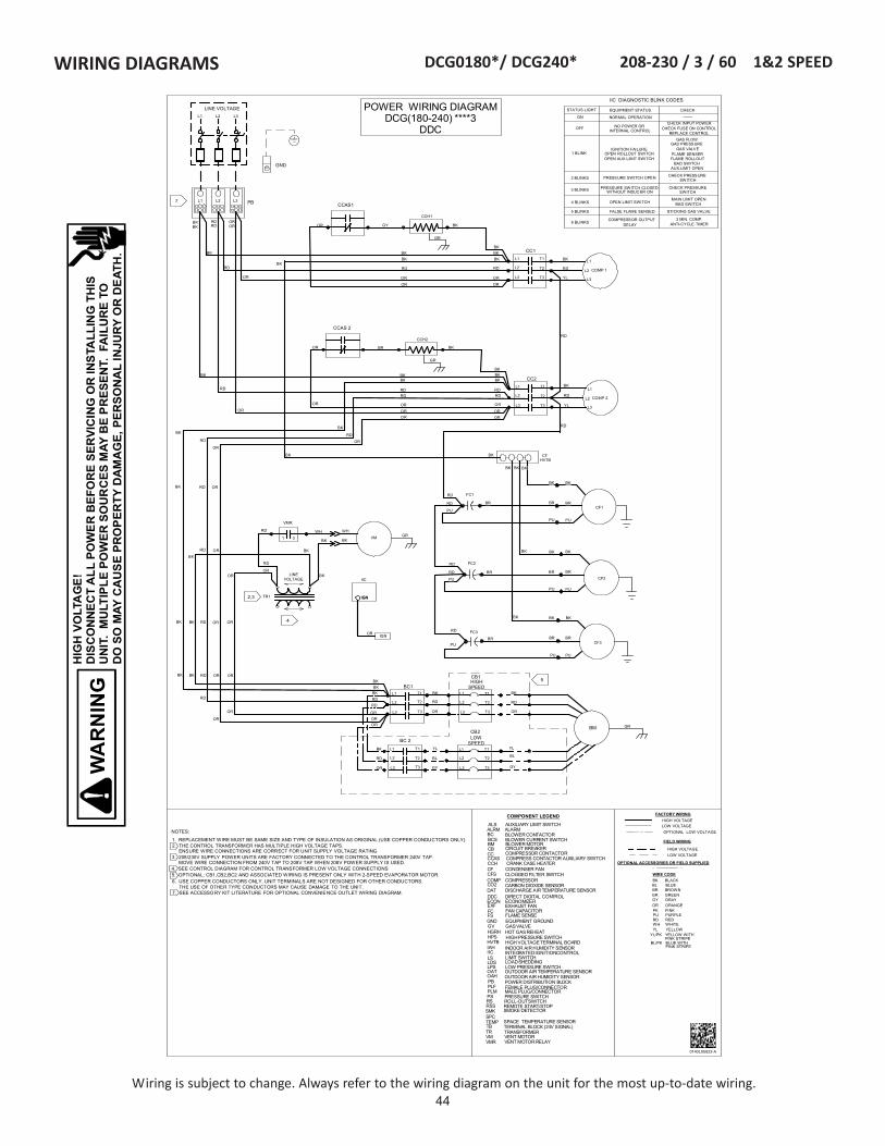
44
HIG
H V
OLT
AG
E!
DIS
CO
NN
ECT
ALL
PO
WE
R B
EFO
RE
SER
VIC
ING
OR
INS
TALL
ING
TH
ISU
NIT
. M
ULT
IPLE
PO
WER
SO
UR
CES
MAY
BE
PR
ESEN
T. F
AIL
UR
E TO
DO
SO
MAY
CA
US
E PR
OP
ERTY
DA
MA
GE,
PER
SON
AL
INJU
RY
OR
DE
ATH
.
Wiring is subject to change. Always refer to the wiring diagram on the unit for the most up-to-date wiring.
WIRING DIAGRAMS
BKBK
RD
RD
OR
T1
0140L05822-A
POWER WIRING DIAGRAMDCG(180-240) ****3
DDC
LOW VOLTAGE
HIGH VOLTAGE
FIELD WIRING
LOW VOLTAGE
FACTORY WIRING
HIGH VOLTAGE
GR GREEN
WIRE CODE
BL BLUE
PU PURPLEPK PINK
WH WHITE
BK BLACK
RD RED
BR BROWN
OR ORANGE
YL YELLOW
GY GRAY
YL/PK YELLOW WITH PINK STRIPE
BL/PK BLUE WITH PINK STRIPE
OPTIONAL LOW VOLTAGE
OPTIONAL ACCESSORIES OR FIELD SUPPLIED
BLOWER CONTACTORBC
COMPRESSOR CONTACTOR
COMPRESSOR
ECONOMIZER
HIGHPRESSURE SWITCH
POWER DISTRIBUTION BLOCKFEMALE PLUG/CONNECTOR
TERMINAL BLOCK (24V SIGNAL)
CC
COMP
ECON
HPS
PBPLF
TB
COMPONENT LEGEND
CIRCUIT BREAKERCB
TR
GND
BCS BLOWER CURRENT SWITCHBM BLOWER MOTOR
CFS CLOGGED FILTER SWITCHCF CONDENSER FAN
DAT DISCHARGE AIR TEMPERATURE SENSORDDC DIRECT DIGITAL CONTROL
CO2 CARBON DIOXIDE SENSOR
FC FAN CAPACITOR
EQUIPMENT GROUNDGV GASVALVE
EXF EXHAUST FAN
IAH INDOOR AIR HUMIDITY SENSOR
LOW PRESSURE SWITCHLPS
RSS REMOTE START/STOP
OAT OUTDOOR AIR TEMPERATURE SENSOROAH OUTDOOR AIR HUMIDITY SENSOR
LDS LOADSHEDDING
SPCTEMP SPACE TEMPERATURE SENSOR
TRANSFORMER
ALRM ALARM
HGRH HOT GASREHEAT
SMK SMOKE DETECTOR
ALS AUXILIARY LIMIT SWITCH
IIC INTEGRATEDIGNITIONCONTROLLS LIMIT SWITCH
PS PRESSURE SWITCHRS ROLL-OUTSWITCH
FS FLAME SENSE
VM VENT MOTORVMR VENT MOTOR RELAY
PLM MALE PLUG/CONNECTOR
L1
L2
L3
T1
T2
T3
COMP 1
BM
L1
L2
L3
T1
T2
T3
RD
GY
BL
YL
RD
BL
BK
OR
RD
YL
BK
OR
GY
OR
RD
OR
RD
YL
BK
CCAS1
BC1
BC 2
CC1
PB
CCH1
GR
L1 L2 L3
GR
5
GND
STATUS LIGHT EQUIPMENT STATUS CHECK
ON
OFF
1 BLINK
2 BLINKS
3 BLINKS
4 BLINKS
5 BLINKS
6 BLINKS
NORMAL OPERATION
NO POWER ORINTERNAL CONTROL
IGNITION FAILUREOPEN ROLLOUT SWITCHOPEN AUX LIMIT SWITCH
PRESSURE SWITCH OPEN
PRESSURE SWITCH CLOSEDWITHOUT INDUCER ON
OPEN LIMIT SWITCH
FALSE FLAME SENSED
COMPRESSOR OUTPUTDELAY
CHECK INPUT POWERCHECK FUSE ON CONTROL
REPLACE CONTROLGAS FLOW
GAS PRESSUREGAS VALVE
FLAME SENSERFLAME ROLLOUT
BAD SWITCHAUX.LIMIT OPEN
CHECK PRESSURESWITCH
CHECK PRESSURESWITCH
MAIN LIMIT OPENBAD SWITCH
STICKING GAS VALVE
3 MIN. COMP.ANTI-CYCLE TIMER
-------
L2
L3
L1
IIC DIAGNOSTIC BLINK CODES
L1 L2 L3
LINE VOLTAGE
RD
7
L1
L2
L3
T2
T3
CB2LOW
SPEED
L1
L2
L3
T1
T2
T3
CB1HIGH
SPEED
L1
L2
L3
T1
T2
T3
RDBK
RD
BK
OR
IGN
LINEVOLTAGE
TR1
4
2,3
IIC
IGN
IGN
OR
VMWH
BK
WH
BKGR
VMR
RD
1 3
BK
OR
RD
ORBKBK RD OR OR
OR
KBYG
BKBK
CF1
CF3BR
PUPU
BR
BK
CF2
NOTES:
1. REPLACEMENT WIRE MUST BE SAME SIZE AND TYPE OF INSULATION AS ORIGINAL (USE COPPER CONDUCTORS ONLY).2. THE CONTROL TRANSFORM ER HAS MULTIPLE HIGH VOLTAGE TAPS.
ENSURE WIRE CONNECTIONS ARE CORRECT FOR UNIT SUPPLY VOLTAGE RATING3. 208/230V SUPPLY POWER UNITS ARE FACTORY CONNECTED TO THE CONTROL TRANSFORMER 240V TAP.
MOVE WIRE CONNECTION FROM 240V TAP TO 208V TAP WHEN 208V POWER SUPPLY IS USED.4. SEE CONTROL DIAGRAM FOR CONTROL TRANSFORMER LOW VOLTAGE CONNECTIONS5. OPTIONAL; CB1,CB2,BC2 AND ASSOCIATED WIRING IS PRESENT ONLY WITH 2-SPEED EVAPORATOR MOTOR.6. USE COPPER CONDUCTORS ONLY. UNIT TERMINALS ARE NOT DESIGNED FOR OTHER CONDUCTORS.
THE USE OF OTHER TYPE CONDUCTORS MAY CAUSE DAMAGE TO THE UNIT.7. SEE ACCESSORY KIT LITERATURE FOR OPTIONAL CONVENIENCE OUTLET WIRING DIAGRAM.
BK
HVTB HIGH VOLTAGETERMINAL BOARD
BK
BK
BK
BR
PUPU
BR
BK BKBK
BR
PUPU
FC1
BR
BK BK
PU
BR
BK BK
RD
RD
BK CFHVTB
BK
RD
OROR
COMP 2
L1
L2
L3
T1
T2
T3OR
RD
YL
BK
CCAS 2
CC2
CCH2
GR
L2
L3
L1
RD
OR
OR
BR BK
BKBK
RD
OROROR
RD
BK
BKBK
OROR
OR
RD
BK
RD
FC2
PU
BRRD
RD
FC3
PUBR
RD
BK
BK
RD
OR
RD
BKBK
BK
OR
OR
OR
BK
ORRD
BK
RD
OR
BK
BK
OR
RD OR OR
BK BK RD OR OR
BK RD OR
RD OR
BK
CCAS COMPRESS CONTACTOR AUXILIARY SWITCHCCH CRANK CASE HEATER
DCG0180*/ DCG240* 208-230 / 3 / 60 1&2 SPEED

45
HIG
H V
OLT
AG
E!
DIS
CO
NN
ECT
ALL
PO
WE
R B
EFO
RE
SER
VIC
ING
OR
INS
TALL
ING
TH
ISU
NIT
. M
ULT
IPLE
PO
WER
SO
UR
CES
MAY
BE
PR
ESEN
T. F
AIL
UR
E TO
DO
SO
MAY
CA
US
E PR
OP
ERTY
DA
MA
GE,
PER
SON
AL
INJU
RY
OR
DE
ATH
.
Wiring is subject to change. Always refer to the wiring diagram on the unit for the most up-to-date wiring.
WIRING DIAGRAMS DCG0180*/ DCG240* 460, 575 / 3 / 60 1&2 SPEED
0140L05684-A
BKBK
RD
RD
OR
T1
POWER WIRING DIAGRAMDCG(180-240) ****4,7
DDC
LOW VOLTAGE
HIGH VOLTAGE
FIELD WIRING
LOW VOLTAGE
FACTORY WIRING
HIGH VOLTAGE
GR GREEN
WIRE CODE
BL BLUE
PU PURPLEPK PINK
WH WHITE
BK BLACK
RD RED
BR BROWN
OR ORANGE
YL YELLOW
GY GRAY
YL/PK YELLOW WITHPINK STRIPE
BL/PK BLUE WITHPINK STRIPE
OPTIONAL LOW VOLTAGE
OPTIONAL ACCESSORIES OR FIELD SUPPLIED
BLOWERCONTACTORBC
COMPRESSORCONTACTOR
COMPRESSOR
ECONOMIZER
HIGH PRESSURE SWITCH
POWERDISTRIBUTION BLOCKFEMALEPLUG/CONNECTOR
TERMINAL BLOCK(24V SIGNAL)
CC
COMP
ECON
HPS
PBPLF
TB
COMPONENT LEGEND
CIRCUIT BREAKERCB
TR
GND
BCS BLOWER CURRENT SWITCHBM BLOWER MOTOR
CFS CLOGGED FILTER SWITCHCF CONDENSER FAN
DAT DISCHARGEAIR TEMPERATURE SENSORDDC DIRECT DIGITALCONTROL
CO2 CARBON DIOXIDE SENSOR
FC FAN CAPACITOR
EQUIPMENTGROUNDGV GASVALVE
EXF EXHAUST FAN
IAH INDOOR AIR HUMIDITY SENSOR
LOW PRESSURE SWITCHLPS
RSS REMOTE START/STOP
OAT OUTDOOR AIR TEMPERATURE SENSOROAH OUTDOOR AIR HUMIDITY SENSOR
LDS LOAD SHEDDING
SPCTEMP SPACE TEMPERATURE SENSOR
TRANSFORMER
ALRM ALARM
HGRH HOTGASREHEAT
SMK SMOKEDETECTOR
ALS AUXILIARY LIMIT SWITCH
IIC INTEGRATEDIGNITION CONTROLLS LIMIT SWITCH
PS PRESSURE SWITCHRS ROLL-OUT SWITCH
FS FLAME SENSE
VM VENTMOTORVMR VENTMOTOR RELAY
PLM MALE PLUG/CONNECTOR
L1
L2
L3
T1
T2
T3
COMP 1
BM
L1
L2
L3
T1
T2
T3
RD
GY
BL
YL
RD
BL
BK
OR
RD
YL
BK
OR
GY
OR
RD
OR
RD
YL
BK
CCAS1
BC1
BC 2
CC1
PB
CCH1
GR
L1 L2 L3
GR
5
GND
STATUS LIGHT EQUIPMENT STATUS CHECK
ON
OFF
1 BLINK
2 BLINKS
3 BLINKS
4 BLINKS
5 BLINKS
6 BLINKS
NORMAL OPERATION
NO POWER ORINTERNAL CONTROL
IGNITION FAILUREOPEN ROLLOUT SWITCHOPEN AUX LIMIT SWITCH
PRESSURE SWITCH OPEN
PRESSURE SWITCH CLOSEDWITHOUT INDUCER ON
OPEN LIMIT SWITCH
FALSE FLAME SENSED
COMPRESSOR OUTPUTDELAY
CHECK INPUT POWERCHECK FUSE ON CONTROL
REPLACE CONTROLGAS FLOW
GAS PRESSUREGAS VALVE
FLAME SENSERFLAME ROLLOUT
BAD SWITCHAUX.LIMIT OPEN
CHECK PRESSURESWITCH
CHECK PRESSURESWITCH
MAIN LIMIT OPENBAD SWITCH
STICKING GAS VALVE
3 MIN. COMP.ANTI-CYCLE TIMER
-------
L2
L3
L1
IIC DIAGNOSTIC BLINK CODES
L1 L2 L3
LINE VOLTAGE
RD
7
L1
L2
L3
T2
T3
CB2LOW
SPEED
L1
L2
L3
T1
T2
T3
CB1HIGH
SPEED
L1
L2
L3
T1
T2
T3
RDBK
RD
BK
OR
IGN
LINEVOLTAGE
TR1
4
2,3 IIC
IGN
IGN
OR
WH
VMR
RD1 3
BK
OR
RD
ORBKBK RD OR OR
OR
KBYG
BKBK
CF1
CF3BR
PUPU
BR
BK
CF2
NOTES:1. REPLACEMENT WIRE MUST BE SAME SIZE AND TYPE OF INSULATION AS ORIGINAL (USE COPPER CONDUCTORS ONLY).2. THE CONTROL TRANSFORMER HAS MULTIPLE HIGH VOLTAGE TAPS.
ENSURE WIRE CONNECTIONS ARE CORRECT FOR UNIT SUPPLY VOLTAGE RATING3. 208/230V SUPPLY POWER UNITS ARE FACTORY CONNECTED TO THE CONTROL TRANSFORMER 240V TAP.
MOVE WIRE CONNECTION FROM 240V TAP TO 208V TAP WHEN 208V POWER SUPPLY IS USED.4. SEE CONTROL DIAGRAM FOR CONTROL TRANSFORMER LOW VOLTAGE CONNECTIONS5. OPTIONAL; CB1,CB2,BC2 AND ASSOCIATED WIRING IS PRESENT ONLY WITH 2-SPEED EVAPORATOR MOTOR.6. USE COPPER CONDUCTORS ONLY. UNIT TERMINALS ARE NOT DESIGNED FOR OTHER CONDUCTORS.
THE USE OF OTHER TYPE CONDUCTORS MAY CAUSE DAMAGE TO THE UNIT.7. SEE ACCESSORY KIT LITERATURE FOR OPTIONAL CONVENIENCE OUTLET WIRING DIAGRAM.
BK
HVTB HIGH VOLTAGETERMINAL BOARD
BK
BK
BK
BR
PUPU
BR
BK BKBK
BR
PUPU
FC1
BR
BK BK
PU
BR
BK BK
RD
RD
BK CFHVTB
BK
RD
OROR
COMP 2
L1
L2
L3
T1
T2
T3OR
RD
YL
BK
CCAS 2
CC2
CCH2
GR
L2
L3
L1
RD
OR
OR
BR BK
BKBK
RD
OROROR
RD
BK
BKBK
OROR
OR
RD
BK
RD
FC2
PU
BRRD
RD
FC3
PUBR
RD
BK
BK
RD
OR
BK
BK
BK
OR
OR
OR
BK
OR
RD
BK
RD
OR
BK
BK
OR
RD OR OR
BK BK RD OR OR
BK RD OR
RD OR
BK
CCAS COMPRESS CONTACTORAUXILIARY SWITCHCCH CRANK CASE HEATER
VM GR
WH
BK
BK
TR3 COM230V
460VOR575V
ORBK RD
OR
OR
BK
RD
OR
BK
BK
OR

46
HIG
H V
OLT
AG
E!
DIS
CO
NN
ECT
ALL
PO
WE
R B
EFO
RE
SER
VIC
ING
OR
INS
TALL
ING
TH
ISU
NIT
. M
ULT
IPLE
PO
WER
SO
UR
CES
MAY
BE
PR
ESEN
T. F
AIL
UR
E TO
DO
SO
MAY
CA
US
E PR
OP
ERTY
DA
MA
GE,
PER
SON
AL
INJU
RY
OR
DE
ATH
.
Wiring is subject to change. Always refer to the wiring diagram on the unit for the most up-to-date wiring.
WIRING DIAGRAMS DCG0180*/ DCG240* 208-230, 460, 575 / 3 / 60 1 SPEED
0140L05683-A
NOTES:
1. REPLACEMENT WIRE MUST BE SAME SIZE AND TYPE OF INSULATION AS ORIGINAL (AT LEAST 105° C).USE COPPER CONDUCTORS ONLY.USE N.E.C. CLASS 2 WIRE FOR ALL LOW VOLTAGE FIELD CONNECTIONS.
IF OPTIONAL SMOKE DETECTOR IS INSTALLED, REMOVE RED JUMPER WIRE CONNECTIONS TB1-XS TO TB1-ES.
DISCHARGE AIR TEMPERATURE SENSOR SHIPPED WITH UNIT IN CONTROL BOX. INSTALL AND CONNECTPER THE ATTACHED INSTRUCTIONS/WIRING DIAGRAM.
IF OPTIONAL ECONOMIZER IS INSTALLED, CONNECT ECON PLF TO ECONOMIZER. ECONOMIZER PLUG LOCATEDIN THE RETURN AIR COMPARTMENT.
SEE POWER DIAGRAM FOR CONTROL TRANSFORMER (TR1) HIGH VOLTAGE CONNECTIONS.
2
3
4
CONTROL WIRING DIAGRAMDCG(180-240) ****B
DDC
BC
CC1
CC2
ECON
XS(CLASS2)
BK
DA
BCS
OAT
ESPSCS
TB1 T124VAC
CFS
RSS
LDS
CO2
T2
T3
T4
T5
LPS1
HPS2
HPS1
LPS2
BL/PK
BL/PK
YL/PK
YL/PK
PK
BK
BK
GND24 VAC(PWR)
OAHVOUT (DC)
GND24VAC(COM)
24 VAC(PWR)
VOUT (DC)
VOUT (DC)24 VAC(PWR)
IAH
GND
BI8
BI5
121110
1
COM3-8RLY8
BI1BI2BI3BI4
BI7
BR
RDCOM3-8
RLY7RLY6RLY5RLY4RLY3
COM1
PU
(OAT)
(CFS)
(EMER)(FAN PROV)
(HEAT 2)(HEAT 1)
BI6 (SHED)
RLY1RLY2COM2
(24V IN)(ECON PWR)
(EXF)(ALRM)
(ECON DMPR)
(OAH)
(ISOL GND)
(CO2)
2345678
123456789
DDC (CLASS2)
(ECON FB)
C(CLASS2)TB2
DAT
(COMP2 OUT)(COMP1 OUT)(COMP1 IN)
(COMP2 IN)
YL
YL
WHBR
654321AO1
AO2AO3AO4GNDGND
AG
SPCTEMPTEMP
GNDSTPT OFFSET
BK
PU
RD
BK
PUBK BK
WH WH
PK
WHBR
GR
GR
BR WH
87654321
9AI3
AI8AI7AI6AI5AI4
AI1AI2
AGNDAGND
10
WH WH
PLF
WH
WH
4
-t°
3
BAC NET3T-21(BAC
NET)R+SH
RD
BL
BL
(SPC TMP)
(SUPPLY AIR TMP)
(SPC HUM)
(COMP PRESS 1)
(BLOWER STAGE 1)
(COMP PRESS 2)
(SPC SLIDE ADJ)
(RMT STRT/STP)
-t°
PU
BR
RD
GR
SMK/EMG TR1
PUYL
PU
BL/PK
BL/PK
YL
PK
YL/PKPK
YL/PK YLPK
YL
PU
BLRD
GR
24V
RD
LINE VOLTAGE
PK
PKPKPKPK
YL BK
YL PKPU
PK
PK
RD
BK
GR
BLYL
PUBLBL
BL
BL
YL
BLBLBK
PK
BL
4
21
65
3
EXF CNTL RLYTWISTEDPAIR
GRD10VDC
ALRM CNTL RLY
GRD10VDC
BR
RD
WH
RD
RD
BR
GRGR
GR
GR BK
BK
PU
PUPU
PU
PU
PUPU
BK
BK
YL
YL
PU
PU
PU PUYL
PK
PKPKPK PKPK BL
BLBLBL
BL
2
2
RDRD RD
GRRD
RD
PURD
BKRD
BK
BR
BR
BR
GR
BL
5
PK
10
IIC
PS
ALS
LS
RS 1ST STG COM
GV
FS
VMR
RDRD
RD
3A
24 VAC PWR 1234568
24 VAC COMGV OUT
TMP LMT OUTTMP LMT IN
PRESS SW INPRESS SW OUT
HEAT INFLAME SENSE
IGNITOR
PU PU
24 VACPWR
L1L1
RDRDRD
YL
L2L2L2L2
BLPK
YL
BL
BR
GYBL
D1
BL
PK
PU
BL
2ND STG
24 VACCOM
VENT MTR
F1
F1
HEAT BK
PK
WHYL
BR
WH
BL
BL
YL
BR
BK
BR
BR
BK
WH
BK
BR
WH
WHBR
PK
PK
BK
BK
21
21
BRWH
BR WH
PK
BL
BL
BK
BK
HTRPLF1
HTRPLM1
BL
BL
BL
BK
BK
5
PK
WH
BL
PK
PK
PK
PK
PK
PK
PK
PK BL
WH
BK
BRWH
BL GY
BLGY
GY
PU PU
YLYL
RD
YL
YL YL
BL
GND
24VAC
1
2

47
HIG
H V
OLT
AG
E!
DIS
CO
NN
ECT
ALL
PO
WE
R B
EFO
RE
SER
VIC
ING
OR
INS
TALL
ING
TH
ISU
NIT
. M
ULT
IPLE
PO
WER
SO
UR
CES
MAY
BE
PR
ESEN
T. F
AIL
UR
E TO
DO
SO
MAY
CA
US
E PR
OP
ERTY
DA
MA
GE,
PER
SON
AL
INJU
RY
OR
DE
ATH
.
Wiring is subject to change. Always refer to the wiring diagram on the unit for the most up-to-date wiring.
WIRING DIAGRAMS DCG0180*/ DCG240* 208-230, 460, 575 / 3 / 60 2 SPEED
0140L05821-A
NOTES:
1. REPLACEMENT WIRE MUST BE SAME SIZE AND TYPE OF INSULATION AS ORIGINAL (AT LEAST 105° C).USE COPPER CONDUCTORS ONLY.USE N.E.C. CLASS 2 WIRE FOR ALL LOW VOLTAGE FIELD CONNEC TIONS.
IF OPTIONAL SMOKE DETECTOR IS INSTALLED, REMOVE RED JUMPER WIRE CONNECTIONS TB1-XS TO TB1-ES.
DISCHARGE AIR TEMPERATURE SENSOR SHIPPED WITH UNIT IN CONTROL BOX. INSTALL AND CONNECTPER THE ATTACHED INSTRUCTIONS/WIRING DIAGRAM.
IF OPTIONAL ECONOMIZER IS INSTALLED, CONNECT ECON PLF TO ECONOMIZER. ECONOMIZER PLUG LOCATEDIN THE RETURN AIR COMPARTMENT.
SEE POWER DIAGRAM FOR CONTROL TRANSFORMER (TR1) HIGH VOLTAGE CONNEC TIONS.
2
3
4
CONTROL WIRING DIAGRAMDCG(180-240) ****V
DDC
CC1
CC2
ECON
XS(CLASS2)
BK
DA
BCS
OAT
ESPSCS
TB1 T124VAC
CFS
RSS
LDS
CO2
T2
T3
T4
T5
LPS1
HPS2
HPS1
LPS2
BL/PK
BL/PK
YL/PK
YL/PK
PK
BK
BK
GND24 VAC(PWR)
OAHVOUT (DC)
GND24VAC(COM)
24 VAC(PWR)
VOUT (DC)
VOUT (DC)24 VAC(PWR)
IAH
GND
BI8
BI5
121110
1
COM3-8RLY8
BI1BI2BI3BI4
BI7
BR
RDCOM3-8
RLY7RLY6RLY5RLY4RLY3
COM1
PU
(OAT)
(CFS)
(EMER)(FAN PROV)
(HEAT 2)(HEAT 1)
BI6 (SHED)
RLY1RLY2COM2
(24V IN)(ECON PWR)
(EXF)(ALRM)
(ECON DMPR)
(OAH)
(ISOL GND)
(CO2)
2345678
123456789
DDC (CLASS2)
(ECON FB)
C(CLASS2)TB2
DAT
(COMP2 OUT)(COMP1 OUT)(COMP1 IN)
(COMP2 IN)
YL
YL
WHBR
654321AO1
AO2AO3AO4GNDGND
AG
SPCTEMPTEMP
GNDSTPT OFFSET
BK
PU
RD
BK
PUBR
WH WH
PK
WHBR
GR
GR
BR WH
87654321
9AI3
AI8AI7AI6AI5AI4
AI1AI2
AGNDAGND
10
WH WH
PLF
WH
WH
4
-t°
3
BAC NET3T-21(BAC
NET)R+SH
RD
BL
BL
(SPC TMP)
(SUPPLY AIR TMP)
(SPC HUM)
(COMP PRESS 1)
(BLOWER STAGE 1)
(COMP PRESS 2)
(SPC SLIDE ADJ)
(RMT STRT/STP)
-t°
PU
BR
RD
GR
SMK/EMG TR1
PUYL
PU
BL/PK
BL/PK
YL
PK
YL/PKPK
YL/PK YLPK
YL
PU
BL
RD
GR
24V
RD
LINE VOLTAGE
PK
PKPKPKPK
YL BK
YL PKPU
PK
PKRD
BK
GR
BLYL
PUBLBL
BL
YL
BLBR
PK
BL
4
21
65
3
EXF CNTL RLYTWISTEDPAIR
GRD10VDC
ALRM CNTL RLY
GRD10VDC
BR
RD
WH
RD
RD
BR
GRGR
GR
GR BK
BK
PU
PUPU
PU
PU
PUPU
BK
BK
YL
YL
PU
PU
PU PUYL
PK
PKPKPK BL
BLBLBL
2
2
RDRD RD
GRRD
RD
PURD
BKRD
BK
BR
BR
BR
GR
BL
5
PK
10
IIC
PS
ALS
LS
RS 1ST STG COM
GV
FS
VMR
RDRD
RD
3A
24 VAC PWR 1234568
24 VAC COMGV OUT
TMP LMT OUTTMP LMT IN
PRESS SW INPRESS SW OUT
HEAT INFLAME SENSE
IGNITOR
PU PU
24 VACPWR
L1L1
RDRDRD
YL
L2L2L2L2
BL
PK
YL
BL
BR
GYBL
D1
BL
PK
PU
BL
2ND STG
24 VACCOM
VENT MTR
F1
F1
HEAT BK
PK
WHYL
BR
WH
BL
BL
YL
BR
BK
BR
BR
BK
WH
BK
BR
WH
WHBR
PK
PK
BK
21
21
BRWH
BR WH
PK
BL
BL
BK
BK
HTRPLF1
HTRPLM1
BL
BL BL
BK
BK
5
PK
WH
BL
PK
PK
PK
PK
PK
PK
PK
PK BL
WH
BRWH
BL GY
BLGY
GY
PU PU
YLYL
RD
YL
YL YL
BL
BC2(LO SPD)
BC1(HI SPD)
BK BK
BKBL
BL
BL
BK
BK
BR
(BLOWER STAGE 2)
BL
GND
24VAC
1
2
PKPK

48
WIRING DIAGRAMS DCG300* 208 / 230 / 3 / 60 1&2 SPEED
Wiring is subject to change. Always refer to the wiring diagram on the unit for the most up-to-date wiring.
HIG
H V
OLT
AG
E!
DIS
CO
NN
ECT
ALL
PO
WE
R B
EFO
RE
SER
VIC
ING
OR
INS
TALL
ING
TH
ISU
NIT
. M
ULT
IPLE
PO
WER
SO
UR
CES
MAY
BE
PR
ESEN
T. F
AIL
UR
E TO
DO
SO
MAY
CA
US
E PR
OP
ERTY
DA
MA
GE,
PER
SON
AL
INJU
RY
OR
DE
ATH
.
014
0L06
605-
A
T1 T2LAT T6
136
5
42
LAR
1 2
1 2
1 2 3LAM
2P
LMP
LF
-t W
LA C
MC
LOW
AM
BO
PTI
ONL3
L2L1
1 2
1 2
1 2 3LAM
1P
LMP
LF
CM
R
24
56 3
1
VM
6
HIG
HS
PE
ED
CB
1
T3T2T1
L3L2L1
BC
1
EM
T3T2T1
L3L2L1
T1T2
T3LA
C M
C T3T2T1
L3L2L1
PLF
PLM
FB 2
F6F5F4
321
321
FB 1
CM
C2
CM
C1 T3T2T1
L3L2L1
CM
1
F3F2F1
T3T2T1
L3L2L1
RD
BR
BR
PU
BK
BR
BK
BK
BR
BK
BR PU
GR
BK
BR
YL
BK YLBR
BK
PU
PU
PU
BK
BK
RD
OR
BK RD
OR
BK
RD
OR
YL (1
1)
YL (1
3)
YL (1
2)
GR
BL
BL
PU
PU
PU
GY
GY
GY
BK BK
BK BK
10
PU
(CLA
SS
2)
BK
BC
S
OA
T
SC
SP
TB1
CFS
RS
S
LDS
CO
2
S MK /
E MG
2
BK
LPS1
HPS
2
YL
HP
S1
LPS
2
PU
BL/
PK
BL/
PK
YL/P
K
YL/P
K
YL/P
K
YL/P
K
PK
BK
BK
YL
PU
YL
GN
D24
VA
COA
HV
OU
T (D
C)
GN
D24
VA
C (C
OM
)24
VA
C
VO
UT
(DC
)
VO
UT
(DC
)
24 V
ACIAH G
ND
BI8
BI5
CO
M3-
8R
LY8
BI1
BI2
BI3
BI4
BI7
GN
D
24VA
C
BR
RD
CO
M3-
8
RLY
7R
LY6
RLY
5R
LY4
RLY
3
CO
M1
BL
PU
PU
OA
T
CFS
EM
ER
GE
NC
Y S
HU
TDO
WN
FAN
PR
OV
SW
HE
AT/S
TG2
HEA
T/S
TG1
YL
BI6
LOA
D S
HE
D
RLY
1R
LY2
CO
M2
24V
RLY
EX
F (S
SR
)/VFD
ALR
M (S
SR
)
EC
ON
DM
PR
OA
H
SP
C T
MP
CO
2 S
EN
SO
R
DD
C (
CLA
SS
2)
EC
ON
FE
ED
BA
CK
C
GR
(CLA
SS
2)TB
2
DA
T
CO
MP/
STG
2C
OM
P/S
TG1
24V
RLY
1
24V
RLY
2
YL
2121
HTR
PLF
1H
TR P
LM1
EC
ON
AO
1 A
O2
AO
3 A
O4
GN
DG
ND
WH
AG
SP
CTE
MP TE
MP
GN
DS
TPT
OFF
SET
GR
BR
BR
BK
BK
PU
PU
GR
GRB
RB
R
BR
GR
BR
BR
GR
RD
RD
RD
BL
BL
BL
BL
PU
PKPK
PU
YL
BK
RD
BK
BK
BK
PU
PU YL
PU
PU
YL
PU
WH
PK
WH
WH
PK
WH
BR
ALR
M-
+
EX
F-
+
GR
GR
AI3
AI8
AI7
AI6
AI5
AI4
AI1
AI2
AG
ND
AG
ND
GR
WH
WH
PU
BK
PU
PLF
WH
BL
TR1
5
RD
BL
4
-t�
3
BA
C N
ET
T-B
AC
NE
TR
+S
H
+-
HG
RH
BR
BL
BL
PU
PU
GR
GR
GR
BL
BL
BL
BL
BL
BL
RD
II C
PS
ALS
LS
RS
1ST
STG
CO
M
GV
FS
VMR
RD
RD
RD
3A
24 V
AC P
WR
1 2 3 4 5 6 8
24 V
AC C
OM
GV
OU
TTM
P L
MT
OU
TTM
P LM
T IN
PR
ES
S S
W IN
PR
ES
S S
W O
UT
HE
AT IN
FLAM
E S
EN
SE
IGN
ITO
R
PU
PU
24 V
ACP
WR
L1 L1
RD
RD
RD
YL
L2 L2 L2 L2
BL
PK
YL
PU
BL
BR GY
GY
BL
D1
BL
PK
PK
PK
BL
PU
BL
2ND
STG
24 V
ACC
OM
VE
NT
MTR
F1 F1
HE
AT
PK
WH
YL
65
43
21
BR
WH
WH
BL
BL
BL
GY
YL
BL
BL
WH
BR
WH
BR
BR
BR
BR
BR
BR
BR
WH
BR
BR
WH
BR
WH
WH
WH
WH
BL
PK
PK
RDRD
PK
PK
BL
RD
BR
BR
BR
WH
BL
BL
24V
CN
TLVO
LTAG
E
LIN
EVO
LTAG
E
RD
BL
RD
WH
BR
BL
BL
SU
PP
LY A
IR T
MP
MO
D H
GR
H
SP
C H
UM
CO
MP
PR
ES
S S
W1
BLO
WE
R/S
TG1
CO
MP
PR
ES
S S
W2
SP
C S
LID
E A
DJ
RM
T S
TRT/
STP
BK
-t�
31
VM
R
UN
US
ED
FSW
24V
AC
RD
RD
T1T2
T3T4
1 2
1 2
1 2 3
FM2
PLM
PLF
-tW
1 2
1 2
1 2 3
FM1
PLM
PLF
-t W
YL
BLO
WE
R/S
TG2/
EXF
CO
ND
FA
N(S
)R
EV V
ALV
E/L
AT
DE
FRO
ST
SW
(ES
)
BK
YL BL
RD
RD
RD
RD
OR
OR
OR
OR
WH
WH
WH
WH
BLPU B
K
YL
BK
PU
PU
PU
BL
BL
BL
BK
BK
RD
RD
YLB
L
BL
BK
1 0
1 1
RD
RD
PK
PK
PK
RD
RD
RD
RD
PK
RD
RD
RD
RD
RD
RD
RD
RD
RD
RD
BR
BR
BK
BR
BK
BR B
K
BR
YL
RD
RD
RD
RD
BK
BK
BK
BK
BL
BL
BLBL
8
T3T2T1
L3L2L1
LOW
SP
EE
D
CB
2
T3T2T1
L3L2L1
BC
2B
R BK
RD
OR
YL BL
GY
YL BL
GY
BK
(1)
BK
(3)
BK
(2)
WH
WH
BK
PU
PU
BL
BL
BL
BL
BL
BL
BL
BL
7
12
7
L3L2
L1
L1 L3
L2
GN
D
L1C
CH
2
CC
H1
PB
CC
1
CC
2
CC
AS
2
CC
AS
1
PU
T3T2T1
L3L2L1
CO
MP
1
RD
LIN
E V
OLT
AGE
L3L2
L1
PH
AS
E M
ON
ITO
R9
YL
BK RD
YL
BK
RD
PU
BK
BK
GY
GY
GY
BK
BK
GR
BK
PU
BK
BK
BL
PU
BL
BK
BR
PU
BL B
L
91 1
1 0
GR
GR
EE
N
WIR
E C
OD
E
BL
B
LUE
PU
PU
RPL
EP
K
P
INK
WH
WH
ITE
BK
BLA
CK
RD
RE
D
BR
BR
OW
N
OR
OR
AN
GE
YL
Y
ELLO
W
GY
GR
AY
BLO
WE
R C
ON
TAC
TOR
BC
CO
MP
RE
SSO
R C
ON
TAC
TOR
CO
MP
RE
SSO
R
EC
ON
OM
IZE
R
HIG
H P
RE
SS
UR
E S
WIT
CH
POW
ER
DIS
TRIB
UTI
ON
BLO
CK
FEM
ALE
PLU
G/C
ON
NEC
TOR
TER
MIN
AL
BLO
CK
(24V
SIG
NA
L)
CC
CO
MP
EC
ON
HP
S
PB PLF TB
CO
MPO
NEN
T LE
GEN
D
CIR
CU
IT B
REA
KE
RC
B
TRG
ND
BC
SBL
OW
ER
CU
RR
ENT
SW
ITC
H
CFS
CLO
GG
ED
FIL
TER
SW
ITC
H
DA
TD
ISC
HA
RG
E A
IR T
EMP
ER
ATU
RE
SE
NSO
RD
DC
DIR
EC
T D
IGIT
AL
CO
NTR
OL
CO
2C
AR
BON
DIO
XID
E S
EN
SOR
FCFA
N C
AP
AC
ITO
R
EQU
IPM
EN
T G
RO
UN
D
GV
GA
S V
ALV
E
EXF
EXH
AU
ST F
AN
IAH
IND
OO
R A
IR H
UM
IDIT
Y S
EN
SOR
LOW
PR
ES
SU
RE
SW
ITC
HLP
S
RS
SR
EMO
TE S
TAR
T/S
TOP
OAT
OU
TDO
OR
AIR
TE
MP
ER
ATU
RE
SE
NS
OR
OA
HO
UTD
OO
R A
IR H
UM
IDIT
Y S
EN
SOR
LDS
LOA
D S
HE
DD
ING
SP
CTE
MP
SP
AC
E T
EM
PE
RA
TUR
E S
EN
SOR
TRA
NSF
OR
ME
R
YL/P
K
YELL
OW
WIT
H
P
INK
STR
IPE
BL/P
K
BLU
E W
ITH
PIN
K S
TRIP
E
ALR
MA
LAR
M
HG
RH
HO
T G
AS
RE
HE
AT
SM
KS
MO
KE
DET
EC
TOR
H
IGH
VO
LTA
GE
FIEL
D W
IRIN
G
L
OW
VO
LTAG
E
FAC
TOR
Y W
IRIN
G
OPT
ION
AL
AC
CES
SOR
IES
OR
FIE
LD S
UPP
LIED
CO
MPO
NEN
TS
OP
TIO
NAL
LO
W V
OLT
AGE
NO
TES
:1.
RE
PLA
CEM
EN
T W
IRE
MU
ST
BE
SA
ME
SIZ
E A
ND
TYP
E
OF
INS
ULA
TIO
N A
S O
RIG
INA
L (A
T LE
AST
105�
C).
U
SE
CO
PP
ER
CO
ND
UC
TOR
S O
NLY
.
US
E N
.E.C
. CLA
SS
2 W
IRE
FOR
ALL
LO
W V
OLT
AG
E
FIE
LD C
ON
NEC
TIO
NS.
I
F O
PTIO
NA
L S
MO
KE
DE
TEC
TOR
IS IN
STA
LLE
D,
R
EM
OV
E R
ED
JU
MP
ER
WIR
E C
ON
NEC
TIO
NS
T
B1-X
S T
O T
B1-E
S.
D
ISC
HA
RG
E A
IR T
EMP
ER
ATU
RE
SE
NS
OR
SH
IPP
ED
W
ITH
UN
IT IN
CO
NTR
OL
BO
X. I
NST
ALL
AN
D C
ON
NEC
T
PE
R T
HE
ATT
AC
HE
D IN
STR
UC
TIO
NS
/WIR
ING
DIA
GR
AM
.
I
F O
PTIO
NA
L E
CO
NO
MIZ
ER
IS IN
STA
LLE
D, C
ON
NEC
T
EC
ON
PLF
TO
EC
ON
OM
IZE
R.
EC
ON
OM
IZE
R P
LUG
LO
CAT
ED
I
N T
HE
RE
TUR
N A
IR C
OM
PA
RTM
EN
T.
2 3 4
5A
LSA
UXI
LIA
RY
LIM
IT S
WIT
CH
IICIN
TIG
RAT
ED
IGN
ITIO
N C
ON
TRO
L
LSLI
MIT
SW
ITC
H
PS
PR
ES
SU
RE
SW
ITC
HR
SR
OLL
-OU
T S
WIT
CH
FMFR
EEZE
STA
T M
OD
ULE
VMV
EN
T M
OTO
RVM
RV
EN
T M
OTO
R R
ELA
Y
H
IGH
VO
LTA
GE
L
OW
VO
LTA
GE
PLM
MA
LE P
LUG
/CO
NN
ECTO
R
6 7 8 9 10 11 12FS
FLAM
E S
EN
SE
FSW
FLO
AT
SW
ITC
H
PM
PH
AS
E M
ON
ITO
R
CO
ND
ENS
ER
MO
TOR
CM
CR
ANK
CA
SE
HE
ATE
RC
CH
CO
ND
ENS
ER
MO
TOR
CO
NTA
CTO
RC
MC
CC
AU
X S
WIT
CH
CC
AS
FU
SE B
LOC
KFB
CO
ND
ENS
ER
MO
TOR
REL
AY
CM
R
LAC
MC
LOW
AM
BIE
NT
CO
ND
ENSE
R M
OTO
RC
ON
TAC
TOR
LAM
LOW
AM
BIE
NT
MO
DU
LELA
RLO
W A
MBI
EN
T R
ELA
YLO
W A
MB
IEN
T TI
ME
RLA
T
EV
AP
OR
ATO
R M
OTO
RE
M
R
ED/B
LAC
K W
IRE
S C
ON
NEC
TED
TO
AP
PRO
PRIA
TE H
IGH
V
OLT
AGE
(460
V O
R 5
75 V
) IN
PUT
TER
MIN
AL O
N P
RIM
AR
Y
SID
E O
F TR
1.
I
F LO
W A
MB
IEN
T K
IT IS
INST
ALLE
D, D
ISC
ON
NEC
T C
ON
DEN
SER
M
OTO
R W
IRE
S F
RO
M C
MC
1 (T
1, T
2, T
3) A
ND
CO
NN
ECT
TO
CO
RR
ES
PON
DIN
G (B
K, B
R, Y
L) W
IRE
S W
ITH
QU
ICK
CO
NN
ECT
T
ERM
INAL
S F
RO
M L
AC M
C (T
1, T
2, T
3). C
ON
NEC
T (B
K, B
R, Y
L)
FR
OM
LAC
MC
(L1,
L2,
L3)
TO
CM
C1
(T1,
T2,
T3)
.
I
F LO
W A
MB
IEN
T K
IT IS
INST
ALLE
D, C
ON
NEC
T G
Y W
IRE
FR
OM
L
AM2
- 3 T
O C
MR
-4. A
LSO
CO
NN
ECT
BL
CO
M W
IRE
S F
RO
M L
AT-
T
6 AN
D L
AM2
-2 T
O T
B 2
(24V
CO
M).
O
PTIO
NA
L; C
B1,
CB
2, B
C2
AND
AS
SOC
IATE
D W
IRIN
G IS
PR
ES
ENT
O
NLY
WIT
H 2
-SP
EED
EV
APO
RAT
OR
MO
TOR
. WH
EN P
RE
SEN
T, B
K
WIR
E F
RO
M D
DC
CO
NTR
OLL
ER
"RLY
4" IN
STAL
LED
ON
BC
2 AN
D B
R
WIR
E F
RO
M D
DC
"RLY
3" IN
STAL
LED
ON
BC
1.
I
F 3
PHA
SE
LIN
E V
OLT
AGE
MO
NIT
OR
IS IN
STAL
LED
,CO
NN
ECT
P
HA
SE
MO
NIT
OR
L1,
L2,
L3
TO T
HE
UN
IT P
OW
ER
BLO
CK
R
ES
PEC
TIV
ELY
. ALS
O, R
EMO
VE
JU
MP
ER
WIR
E C
ON
NEC
TIO
NS
T
B1 -
ES
TO
TB1
- PM
.
I
F FL
OAT
SW
ITC
H IS
INST
ALLE
D, R
EMO
VE
JU
MP
ER
WIR
E
CO
NN
ECTI
ON
S T
B1- P
M T
O T
B1 -
FSW
.
I
F FR
EEZ
E P
RO
TEC
TIO
N M
OD
ULE
IS IN
STAL
LED
, REM
OV
E J
UM
PE
R
CO
NN
ECTI
ON
S T
B1- P
S T
O T
B1 -
FM1
AND
TB1
- FM
1 TO
TB1
- FM
2.
L
AT O
N/O
FF T
IME
SE
TTIN
GS
:
ON
- TI
ME
(LEF
T C
OLU
MN
) : 2
,8 =
ON
O
FF -
TIM
E (
RIG
HT
CO
LUM
N) :
8 =
ON
A
LL O
THER
DIP
SW
ITC
HE
S O
FF
PK P
KP
K
PU
BK
BK
24V
RLY
BR
BL
BL
BK
RD
PU
PU
YL
YL
YL RD
RD
RD
YL BK OR
GY
BL
WH
OR
BK
YLR
D
OR
BK YL
RD
BL
BL
BLBL
GY
BL
WH
WH
WH
WH
WH
-tW
WH
WH
RD
BL
BL
GY
BK
RD
L2L3
YL
PU
BK
RD
BL
BL
GY
BL
BR
WH
PU
YLR
DR
DR
D
YLYLR
D
RD
RD
BK
RD
T5XS
DA
ES
TB1-
T1
FM
1 (F
RE
EZE
MO
NIT
OR
1)
TB1-
T2
FM
2 (F
REE
ZE M
ON
ITO
R2)
TB1-
T3
PM
(PH
AS
E M
ON
ITO
R)
TB1-
T4
FSW
(FLO
AT S
WIT
CH
)TB
1-T5
U
NU
SED
BL
BL
PK
RD
BK
BK
RD
RD
BK
BL
PU
YL
GR
L1 L3
L2T3T2T1
L3L2L1
CO
MP
2
PU
RD
BK
PU
PU
GY
GY
L3L2
L1
PLF
PLM321
321C
M2
GR
BK
BR
PU
BK
BR
PU
BR
BK
BL
GY
BK
RD
BR
BL
OR
BK
RD
OR
BK
RD
BK
BK
RD
RD
RD
OR
PU
YLRD
BK
BR
BK B
R PUB
R
PO
WE
R &
CO
NTR
OL
WIR
ING
DIA
GR
AMD
CG
(300
) ***
(3) (
B, V
) BD
DC
BK
BK
YL
BK
RD
BK RD
RD
BK
RD
BK
BK
BK
RD
BK
RD
RD
PU
BL/
PK
BL/
PK
YL

49
WIRING DIAGRAMS DCG300* 460 / 575 / 3 / 60 1&2 SPEED
Wiring is subject to change. Always refer to the wiring diagram on the unit for the most up-to-date wiring.
HIG
H V
OLT
AG
E!
DIS
CO
NN
ECT
ALL
PO
WE
R B
EFO
RE
SER
VIC
ING
OR
INS
TALL
ING
TH
ISU
NIT
. M
ULT
IPLE
PO
WER
SO
UR
CES
MAY
BE
PR
ESEN
T. F
AIL
UR
E TO
DO
SO
MAY
CA
US
E PR
OP
ERTY
DA
MA
GE,
PER
SON
AL
INJU
RY
OR
DE
ATH
.
014
0L06
604-
A
PO
WE
R &
CO
NTR
OL
WIR
ING
DIA
GR
AMD
CG
(300
) ***
(4,7
) (B,
V) B
DD
C
T1 T2LAT T6
136
5
42
LAR
1 2
1 2
1 2 3LAM
2P
LMP
LF
-t W
LA C
MC
LOW
AM
BO
PTI
ONL3
L2L1
1 2
1 2
1 2 3LAM
1P
LMP
LF
CM
R
24
56 3
1
VM
6
HIG
HS
PE
ED
CB
1
T3T2T1
L3L2L1
BC
1
EM
T3T2T1
L3L2L1
T1T2
T3LA
C M
C T3T2T1
L3L2L1
PLF
PLM
FB 2
F6F5F4
321
321
FB 1
CM
C2
CM
C1 T3T2T1
L3L2L1
CM
1
F3F2F1
T3T2T1
L3L2L1
RD
BR
BR
PU
BK
BR
BK
BK
BR
BK
BR PU
GR
BK
BR
YL
BK YLBR
BK
PU
PU
PU
BK
BK
RD
OR
BK RD
OR
BK
RD
OR
YL (1
1)
YL (1
3)
YL (1
2)
GR
BL
BL
PU
PU
PU
GY
GY
GY
BK BK
BK BK
10
PU
(CLA
SS
2)
BK
BC
S
OA
T
SC
SP
TB1
CFS
RS
S
LDS
CO
2
S MK /
EM
G
2
BK
LPS
1
HPS
2
YL
HP
S1
LPS
2
PU
BL/
PK
BL/
PK
YL/P
K
YL/P
K
YL/P
K
YL/P
K
PK
BK
BK
YL
PU
YL
GN
D24
VA
COA
HV
OU
T (D
C)
GN
D24
VA
C (C
OM
)24
VA
C
VO
UT
(DC
)
VO
UT
(DC
)
24 V
ACIAH G
ND
BI8
BI5
CO
M3-
8R
LY8
BI1
BI2
BI3
BI4
BI7
GN
D
24VA
C
BR
RD
CO
M3-
8
RLY
7R
LY6
RLY
5R
LY4
RLY
3
CO
M1
BL
PU
PU
OA
T
CFS
EM
ER
GE
NC
Y S
HU
TDO
WN
FAN
PR
OV
SW
HE
AT/S
TG2
HE
AT/
STG
1
YL
BI6
LOA
D S
HE
D
RLY
1R
LY2
CO
M2
24V
RLY
EX
F (S
SR
)/VFD
ALR
M (S
SR
)
EC
ON
DM
PR
OAH
SP
C T
MP
CO
2 S
EN
SO
R
DD
C (
CLA
SS
2)
EC
ON
FE
ED
BA
CK
C
GR
(CLA
SS
2)TB
2
DA
T
CO
MP
/STG
2C
OM
P/S
TG1
24V
RLY
1
24V
RLY
2
YL
2121
HTR
PLF
1H
TR P
LM1
EC
ON
AO
1 A
O2
AO
3 A
O4
GN
DG
ND
WH
AG
SP
CTE
MP TE
MP
GN
DS
TPT
OFF
SET
GR
BR
BR
BK
BK
PU
PU
GR
GRB
RB
R
BR
GR
BR
BR
GR
RD
RD
RD
BL
BL
BL
BL
PU
PKPK
PU
YL
BK
RD
BK
BK
BK
PU
PU YL
PU
PU
YL
PU
WH
PK
WH
WH
PK
WH
BR
ALR
M-
+
EX
F-
+
GR
GR
AI3
AI8
AI7
AI6
AI5
AI4
AI1
AI2
AG
ND
AG
ND
GR
WH
WH
PU
BK
PU
PLF
WH
BL
TR1
5
RD
BL
4
-t�
3
BA
C N
ET
T-B
AC
NE
TR
+S
H
+-
HG
RH
BR
BL
BL
PU
PU
GR
GR
GR
BL
BL
BL
BL
BL
BL
RD
II C
PS
ALS
LS
RS
1ST
STG
CO
M
GV
FS
VMR
RD
RD
RD
3A
24 V
AC P
WR
1 2 3 4 5 6 8
24 V
AC C
OM
GV
OU
TTM
P L
MT
OU
TTM
P LM
T IN
PR
ES
S S
W IN
PR
ES
S S
W O
UT
HE
AT IN
FLAM
E S
EN
SE
IGN
ITO
R
PU
PU
24 V
ACP
WR
L1 L1
RD
RD
RD
YL
L2 L2 L2 L2
BL
PK
YL
PU
BL
BR GY
GY
BL
D1
BL
PK
PK
PK
BL
PU
BL
2ND
STG
24 V
ACC
OM
VE
NT
MTR
F1 F1
HE
AT
PK
WH
YL
65
43
21
BR
WH
WH
BL
BL
BL
GY
YL
BL
BL
WH
BR
WH
BR
BR
BR
BR
BR
BR
BR
WH
BR
BR
WH
BR
WH
WH
WH
WH
BL
PK
PK
RDRD
PK
PK
BL
RD
BR
BR
BR
WH
BL
BL
24V
CN
TLVO
LTAG
E
LIN
EVO
LTAG
E
RD
BL
RD
WH
BR
BL
BL
SU
PP
LY A
IR T
MP
MO
D H
GR
H
SP
C H
UM
CO
MP
PR
ES
S S
W1
BLO
WE
R/S
TG1
CO
MP
PR
ES
S S
W2
SP
C S
LID
E A
DJ
RM
T S
TRT/
STP
BK
-t�
31
VM
R
UN
US
ED
TR2
CO
M
230V
460V
OR
575V
OR
RD
RD
RD
FSW
24V
AC
RD
RD
T1T2
T3T4
1 2
1 2
1 2 3
FM2
PLM
PLF
-t W
1 2
1 2
1 2 3
FM1
PLM
PLF
-t W
BK
BK
YL
BLO
WE
R/S
TG2/
EXF
CO
ND
FA
N(S
)R
EV V
ALV
E/L
AT
DE
FRO
ST
SW
(ES
)
BK
YL BL BK
RD
RD
RD
RD
OR
OR
OR
OR
WH
WH
WH
WH
BLPU BK
YL
PU
PU
PU
BL
BL
BL
BK
BK
RD
RD
YLB
L
BL
BK
1 0
1 1
RD
RD
PK
PK
PK
RD
RD
RD
RD
PK
RD
RD
RD
RD
RD
RD
RD
RD
RD
RD
BR
BR
BK
BR
BK
BR B
K
BR
YL
OR
BK
RD
RD
RD
BK
BK
BK
BK
BK
BK
BL
BL
BLBL
8
T3T2T1
L3L2L1
LOW
SP
EE
D
CB
2
T3T2T1
L3L2L1
BC
2B
R BK
RD
OR
YL BL
GY
YL BL
GY
BK
(1)
BK
(3)
BK
(2)
WH
WH
BK
PU
PU
BL
BL
BL
BL
BL
BL
BL
BL
7
12
7
L3L2
L1
L1 L3
L2
GN
D
L1C
CH
2
CC
H1
PB
CC
1
CC
2
CC
AS
2
CC
AS
1
PU
T3T2T1
L3L2L1
CO
MP
1
RD
LIN
E V
OLT
AGE
L3L2
L1
PH
AS
E M
ON
ITO
R9
YL
BK RD
YL
BK
RD
PU
BK
BK
GY
GY
GY
BK
BK
GR
BK
PU
BK
BK
BL
PU
BL
BK
BR
PU
BL B
L
91 1
1 0
GR
GR
EE
N
WIR
E C
OD
E
BL
B
LUE
PU
PU
RPL
EP
K
P
INK
WH
WH
ITE
BK
BLA
CK
RD
RE
D
BR
BR
OW
N
OR
OR
AN
GE
YL
Y
ELLO
W
GY
GR
AY
BLO
WE
R C
ON
TAC
TOR
BC
CO
MP
RE
SSO
R C
ON
TAC
TOR
CO
MP
RE
SSO
R
EC
ON
OM
IZE
R
HIG
H P
RE
SSU
RE
SW
ITC
H
POW
ER
DIS
TRIB
UTI
ON
BLO
CK
FEM
ALE
PLU
G/C
ON
NEC
TOR
TER
MIN
AL
BLO
CK
(24V
SIG
NA
L)
CC
CO
MP
EC
ON
HPS
PB PLF TB
CO
MPO
NEN
T LEG
END
CIR
CU
IT B
REA
KE
RC
B
TRG
ND
BC
SBL
OW
ER
CU
RR
ENT
SW
ITC
H
CFS
CLO
GG
ED
FIL
TER
SW
ITC
H
DA
TD
ISC
HA
RG
E A
IR T
EMP
ER
ATU
RE
SE
NSO
RD
DC
DIR
EC
T D
IGIT
AL
CO
NTR
OL
CO
2C
AR
BON
DIO
XID
E S
EN
SOR
FCFA
N C
AP
AC
ITO
R
EQU
IPM
EN
T G
RO
UN
D
GV
GA
S V
ALV
E
EXF
EX
HA
US
T FA
N
IAH
IND
OO
R A
IR H
UM
IDIT
Y S
EN
SOR
LOW
PR
ES
SU
RE
SW
ITC
HLP
S
RS
SR
EMO
TE S
TAR
T/S
TOP
OAT
OU
TDO
OR
AIR
TE
MP
ER
ATU
RE
SE
NS
OR
OA
HO
UTD
OO
R A
IR H
UM
IDIT
Y S
EN
SOR
LDS
LOA
D S
HE
DD
ING
SP
CTE
MP
SP
AC
E T
EM
PE
RA
TUR
E S
EN
SO
R
TRA
NS
FOR
ME
R
YL/P
K
YELL
OW
WIT
H
P
INK
STR
IPE
BL/P
K
BLU
E W
ITH
PIN
K S
TRIP
E
ALR
MA
LAR
M
HG
RH
HO
T G
AS
RE
HE
AT
SMK
SM
OK
E D
ETE
CTO
R
H
IGH
VO
LTA
GE
FIEL
D W
IRIN
G
L
OW
VO
LTAG
E
FAC
TOR
Y W
IRIN
G
OPT
ION
AL
AC
CES
SOR
IES
OR
FIE
LD S
UPP
LIED
CO
MPO
NEN
TS
OP
TIO
NA
L L
OW
VO
LTAG
E
NO
TES
:1.
RE
PLA
CEM
EN
T W
IRE
MU
ST
BE
SA
ME
SIZ
E A
ND
TYP
E
OF
INS
ULA
TIO
N A
S O
RIG
INA
L (A
T LE
AST
105
� C
).
US
E C
OP
PE
R C
ON
DU
CTO
RS
ON
LY.
U
SE
N.E
.C. C
LAS
S 2
WIR
E FO
R A
LL L
OW
VO
LTA
GE
F
IELD
CO
NN
ECTI
ON
S.
I
F O
PTIO
NA
L S
MO
KE
DE
TEC
TOR
IS IN
STA
LLE
D,
R
EM
OV
E R
ED
JU
MP
ER
WIR
E C
ON
NEC
TIO
NS
T
B1-X
S T
O T
B1-E
S.
D
ISC
HA
RG
E A
IR T
EMP
ER
ATU
RE
SE
NSO
R S
HIP
PE
D
WIT
H U
NIT
IN C
ON
TRO
L B
OX.
IN
STA
LL A
ND
CO
NN
ECT
P
ER
TH
E A
TTA
CH
ED
INS
TRU
CTI
ON
S/W
IRIN
G D
IAG
RAM
.
I
F O
PTIO
NA
L E
CO
NO
MIZ
ER
IS IN
STA
LLE
D, C
ON
NEC
T
EC
ON
PLF
TO
EC
ON
OM
IZE
R.
EC
ON
OM
IZE
R P
LUG
LO
CA
TED
I
N T
HE
RE
TUR
N A
IR C
OM
PA
RTM
EN
T.
2 3 4
5AL
SA
UXI
LIA
RY
LIM
IT S
WIT
CH
IICIN
TIG
RA
TED
IGN
ITIO
N C
ON
TRO
L
LSLI
MIT
SW
ITC
H
PS
PR
ES
SU
RE
SW
ITC
HR
SR
OLL
-OU
T S
WIT
CH
FMFR
EEZE
STA
T M
OD
ULE
VMV
EN
T M
OTO
RV
MR
VE
NT
MO
TOR
RE
LAY
H
IGH
VO
LTA
GE
L
OW
VO
LTAG
E
PLM
MA
LE P
LUG
/CO
NN
ECTO
R
6 7 8 9 10 11 12FS
FLAM
E S
EN
SE
FSW
FLO
AT
SW
ITC
H
PM
PH
AS
E M
ON
ITO
R
CO
ND
ENS
ER
MO
TOR
CM
CR
ANK
CA
SE
HE
ATE
RC
CH
CO
ND
ENS
ER
MO
TOR
CO
NTA
CTO
RC
MC
CC
AU
X SW
ITC
HC
CAS
FU
SE
BLO
CK
FB
CO
ND
ENS
ER
MO
TOR
REL
AY
CM
R
LAC
MC
LOW
AM
BIE
NT
CO
ND
ENSE
R M
OTO
RC
ON
TAC
TOR
LAM
LOW
AM
BIE
NT
MO
DU
LELA
RLO
W A
MBI
EN
T R
ELA
YLO
W A
MB
IEN
T TI
ME
RLA
T
EV
AP
OR
ATO
R M
OTO
REM
R
ED/B
LAC
K W
IRE
S C
ON
NEC
TED
TO
AP
PRO
PRIA
TE H
IGH
V
OLT
AGE
(460
V O
R 5
75 V
) IN
PUT
TER
MIN
AL O
N P
RIM
AR
Y
SID
E O
F TR
1.
I
F LO
W A
MB
IEN
T K
IT IS
INST
ALLE
D, D
ISC
ON
NEC
T C
ON
DEN
SER
M
OTO
R W
IRE
S F
RO
M C
MC
1 (T
1, T
2, T
3) A
ND
CO
NN
ECT
TO
CO
RR
ES
PON
DIN
G (B
K, B
R, Y
L) W
IRE
S W
ITH
QU
ICK
CO
NN
ECT
T
ER
MIN
ALS
FR
OM
LAC
MC
(T1,
T2,
T3)
. CO
NN
ECT
(BK
, BR
, YL)
FRO
M L
AC M
C (L
1, L
2, L
3) T
O C
MC
1 (T
1, T
2, T
3).
I
F LO
W A
MB
IEN
T K
IT IS
INST
ALLE
D, C
ON
NEC
T G
Y W
IRE
FR
OM
L
AM2
- 3 T
O C
MR
-4. A
LSO
CO
NN
ECT
BL
CO
M W
IRE
S F
RO
M L
AT-
T
6 AN
D L
AM2
-2 T
O T
B 2
(24V
CO
M).
O
PTIO
NA
L; C
B1,
CB
2, B
C2
AND
AS
SOC
IATE
D W
IRIN
G IS
PR
ES
ENT
O
NLY
WIT
H 2
-SP
EED
EV
APO
RAT
OR
MO
TOR
. WH
EN P
RE
SEN
T, B
K
WIR
E F
RO
M D
DC
CO
NTR
OLL
ER
"RLY
4" IN
STAL
LED
ON
BC
2 AN
D B
R
WIR
E F
RO
M D
DC
"RLY
3" IN
STA
LLED
ON
BC
1.
I
F 3
PHA
SE
LIN
E V
OLT
AGE
MO
NIT
OR
IS IN
STAL
LED
,CO
NN
ECT
P
HA
SE
MO
NIT
OR
L1,
L2,
L3
TO T
HE
UN
IT P
OW
ER
BLO
CK
R
ES
PEC
TIV
ELY
. ALS
O, R
EMO
VE
JU
MP
ER
WIR
E C
ON
NEC
TIO
NS
T
B1
- ES
TO
TB1
- PM
.
I
F FL
OAT
SW
ITC
H IS
INST
ALLE
D, R
EMO
VE
JU
MP
ER
WIR
E
CO
NN
ECTI
ON
S T
B1-
PM
TO
TB1
- FS
W.
I
F FR
EEZ
E P
RO
TEC
TIO
N M
OD
ULE
IS IN
STAL
LED
, REM
OV
E J
UM
PE
R
CO
NN
ECTI
ON
S T
B1-
PS
TO
TB1
- FM
1 AN
D T
B1 -
FM1
TO T
B1 -
FM2.
L
AT O
N/O
FF T
IME
SE
TTIN
GS
:
ON
- TI
ME
(LEF
T C
OLU
MN
) : 2
,8 =
ON
O
FF -
TIM
E (
RIG
HT
CO
LUM
N) :
8 =
ON
A
LL O
THER
DIP
SW
ITC
HE
S O
FF
PK P
KP
K
YL
BK
BK
24V
RLY
BR
BL
BL
BK
RD
PU
PU
YL
YL
YL RD
RD
RD
YL BK OR
GY
BL
WH
OR
BK
YLR
D
OR
BK YL
RD
BL
BL
BLBL
GY
BL
WH
WH
WH
WH
WH
-tW
WH
WH
RD
BL
BL
GY
BK
RD
L2L3
YL
PU
BK
RD
BL
BL
GY
BL
BR
WH
PU
YLR
DR
D
BK
RD
YLYLR
D
RD
RD
BK
RD
T5XS
DA
ES
TB1-
T1
FM
1 (F
RE
EZE
MO
NIT
OR
1)
TB1-
T2
FM
2 (F
REE
ZE M
ON
ITO
R2)
TB1-
T3
PM
(PH
AS
E M
ON
ITO
R)
TB1-
T4
FSW
(FLO
AT S
WIT
CH
)TB
1-T5
U
NU
SE
D
BL
BL
PK
RD
BK
BK
RD
RD
BK
BL
PU
YL
GR
L1 L3
L2T3T2T1
L3L2L1
CO
MP
2
PU
RD
BK
PU
PU
GY
GY
L3L2
L1
PLF
PLM321
321C
M2
GR
BK
BR
PU
BK
BR
PU
BR
BK
BL
GY
BK
RD
BR
BL
OR
BK
RD
OR
BK
RD
BK
BK
RD
RD
RD
OR
PU
YLRD
BK
BR
BK B
R PUB
R
BK
PU
BK B
K
BK
BK OR
BK
OR
BK
OR
BK
OR
PUYL
BL/
PK
BL/
PK

50
Start-up Checklist*Store in job file
Pre Start-Up(Check each item as completed)
Verify all packaging material has been removed.
Remove all shipping brackets per installation instructions.
Verify the job site voltage agrees with the unit serial plate.
Verify condensate connection is installed per installation instructions.
Verify proper clearance around the unit for safety, service, maintenance and proper unit operation.
Verify proper weatherproofing of all ductwork, roof curbs and electrical connections.
Check that the flue screen is in place.
Check gas piping for leaks.
Verify gas pressure to the unit is within the range specified on the serial plate.
Check to ensure that all fans, pulleys and wheels are secure.
Check for proper belt tension and alignment per installation instructions.
Check refrigerant piping for rubbing and leaks. Repair if necessary.
Check unit wiring to ensure it is not in contact with refrigerant piping or sharp metal edges.
Check all electrical connections and terminals. Tighten as needed.
Verify that the crankcase heaters have been energized for 24 hours.
Verify the scroll compressor(s) are rotating in the right direction.
Verify all accessories are installed and operating correctly.
Check filters and replace if necessary.
Verify the installation of the thermostat.
9/2014
Date: ___________________________________
Model Number: ___________________________________
Serial Number: ___________________________________
Technician: ___________________________________
Location: __________________________________________
__________________________________________
__________________________________________
Unit #: __________________________________________
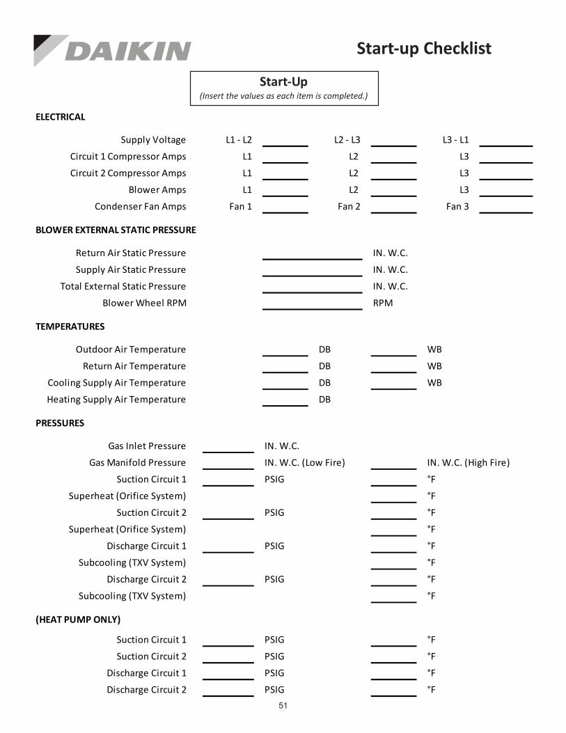
51
Start-up Checklist
L1 - L2 L2 - L3 L3 - L1
L1 L2 L3
L1 L2 L3
L1 L2 L3
Fan 1 Fan 2 Fan 3
IN. W.C.
IN. W.C.
IN. W.C.
RPM
DB WB
DB WB
DB WB
DB
IN. W.C.
IN. W.C. (Low Fire) IN. W.C. (High Fire)
PSIG °F
°F
PSIG °F
°F
PSIG °F
°F
PSIG °F
°F
PSIG °F
PSIG °F
PSIG °F
PSIG °F
BLOWER EXTERNAL STATIC PRESSURE
Return Air Static Pressure
Supply Air Static Pressure
Supply Voltage
Circuit 1 Compressor Amps
Circuit 2 Compressor Amps
Blower Amps
Condenser Fan Amps
ELECTRICAL
Total External Static Pressure
Blower Wheel RPM
TEMPERATURES
Outdoor Air Temperature
Return Air Temperature
Cooling Supply Air Temperature
Discharge Circuit 1
Heating Supply Air Temperature
PRESSURES
Gas Inlet Pressure
Gas Manifold Pressure
Suction Circuit 1
Suction Circuit 2
Discharge Circuit 2
Superheat (Orifice System)
Superheat (Orifice System)
Subcooling (TXV System)
Subcooling (TXV System)
Discharge Circuit 1
Discharge Circuit 2
(HEAT PUMP ONLY)
Suction Circuit 1
Suction Circuit 2
Start-Up(Insert the values as each item is completed.)

52
© 2013 - 2017 5151 San Felipe St., Suite 500, Houston, TX 77056
www.daikinac.com
Our continuing commitment to quality products may mean a change in specifications without notice.