
LIGHT BOX & OPTICAL SET - ‘Hodson’ · PDF fileChapter 1: Reflection (red) Chapter...
47
INSTRUCTION SHEET INDUSTRIAL EQUIPMENT & CONTROL PTY.LTD. 61-65 McClure St. Thornbury. 3071 Melbourne. Australia Tel: 61 (0)3 9497 2555 Fax: 61 (0)3 9497 2166 h l 2 0 6 0 - 0 0 1 b o o k . D O C 2 7 - J u n - 0 6 1 LIGHT BOX & OPTICAL SET - ‘Hodson’ Cat: HL2060-001 Light Box book KIT COMPONENTS: Light Box & Collimating Lens Rectangular Block Three Slit Former Plates Half Round Block Set of 8 Colour Filters & Plates 45 o 45 o 90 o Prism Colours: 60 o 30 o 90 o Prism Red Orange 60 o 60 o 60 o Prism Yellow Green Bi-Concave Lens Blue Violet Bi-Convex Lens Cyan Magenta Bi-Convex Lens (thick) Spare Lamp: Axial, 12V.30W Plane Mirror Foam Housing of 3 parts Half Round Mirror Experiment Book Parabolic Mirror IMPORTANT NOTE The ‘Hodson’ Light Box is virtually unbreakable and is not affected by heating during prolonged operation. However care should be taken to ensure that the colour filters do not remain in position for long periods otherwise radiant heat from the lamp may affect them. To ensure correct ventilation whilst using three colour filters simultaneously, the ‘ray end’ of the box should be left uncovered and the under side of the box should permit the free passage of air. For use with 12V.AC/DC power source at 2 to 3 amps. CAUTION: WHEN UNIT IS OPERATING, THE LAMP IS VERY HOT. DO NOT TOUCH. REPLACEMENT LAMP: Axial Filament, Halogen, type ‘G4’, 2 pin, 12V. 30W. When replacing the lamp, do not remove the lamp socket. Allow the globe to cool, reach through the openings and pull lamp firmly from the small socket. Hold the new lamp in a plastic covering so that fingers do not touch the glass, align the two small pins with the holes in the socket and press firmly into place. TO CONVERT OLD LAMP SYSTEM TO NEW LAMP SYSTEM: Twist old model lamp socket to release it from the Light Box and remove the lamp from the socket. Fit the new style 2 pin globe into the new lamp socket and position the socket in the hole. Rotate it until the two lugs engage and lock the socket from turning. Invert the box while holding the socket in place and, on the inside of the box and through the end opening, slide the “keeper plate” into the groove provided in the socket. The small “pips” on the “keeper plate” should be pressing against the Light Box body. When the “keeper plate” is fully engaged into the groove of the lamp socket, the socket is fully secure. REMOVAL OF LAMP SOCKET: The lamp socket can be removed from the box by sliding the “keeper plate” away from the groove in the socket and extracting it through the open end of the box. UPGRADES: Low cost upgrade kits are available to change your old style Light Box into the new style lamp socket, lamp and sliding collimating lens. Ask you equipment supplier for more details.
Transcript of LIGHT BOX & OPTICAL SET - ‘Hodson’ · PDF fileChapter 1: Reflection (red) Chapter...

INSTRUCTION SHEET
I N D U S T R I A L E Q U I P M E N T & C O N T R O L P T Y . L T D .6 1 - 6 5 M c C l u r e S t . T h o r n b u r y . 3 0 7 1 M e l b o u r n e . A u s t r a l i a
T e l : 6 1 ( 0 ) 3 9 4 9 7 2 5 5 5 F a x : 6 1 ( 0 ) 3 9 4 9 7 2 1 6 6h l 2 0 6 0 - 0 0 1 b o o k . D O C 2 7 - J u n - 0 6
1
LIGHT BOX & OPTICAL SET - ‘Hodson’ Cat: HL2060-001 Light Box book
KIT COMPONENTS:Light Box & Collimating Lens Rectangular BlockThree Slit Former Plates Half Round BlockSet of 8 Colour Filters & Plates 45o 45o 90o PrismColours: 60o 30o 90o PrismRed Orange 60o 60o 60o PrismYellow Green Bi-Concave LensBlue Violet Bi-Convex LensCyan Magenta Bi-Convex Lens (thick)Spare Lamp: Axial, 12V.30W Plane MirrorFoam Housing of 3 parts Half Round MirrorExperiment Book Parabolic Mirror
IMPORTANT NOTE The ‘Hodson’ Light Box is virtually unbreakable and is not affected by heatingduring prolonged operation. However care should be taken to ensure that the colour filters do not remainin position for long periods otherwise radiant heat from the lamp may affect them.To ensure correct ventilation whilst using three colour filters simultaneously, the ‘ray end’ of the boxshould be left uncovered and the under side of the box should permit the free passage of air.For use with 12V.AC/DC power source at 2 to 3 amps.
CAUTION: WHEN UNIT IS OPERATING, THE LAMP IS VERY HOT. DO NOT TOUCH.REPLACEMENT LAMP: Axial Filament, Halogen, type ‘G4’, 2 pin, 12V. 30W.When replacing the lamp, do not remove the lamp socket. Allow the globe to cool, reach through theopenings and pull lamp firmly from the small socket. Hold the new lamp in a plastic covering so thatfingers do not touch the glass, align the two small pins with the holes in the socket and press firmly intoplace.
TO CONVERT OLD LAMP SYSTEM TO NEW LAMP SYSTEM: Twist old model lamp socket to releaseit from the Light Box and remove the lamp from the socket. Fit the new style 2 pin globe into the newlamp socket and position the socket in the hole. Rotate it until the two lugs engage and lock the socketfrom turning. Invert the box while holding the socket in place and, on the inside of the box and through theend opening, slide the “keeper plate” into the groove provided in the socket. The small “pips” on the“keeper plate” should be pressing against the Light Box body. When the “keeper plate” is fully engagedinto the groove of the lamp socket, the socket is fully secure.
REMOVAL OF LAMP SOCKET: The lamp socket can be removed from the box by sliding the “keeperplate” away from the groove in the socket and extracting it through the open end of the box.
UPGRADES: Low cost upgrade kits are available to change your old style Light Box into the new stylelamp socket, lamp and sliding collimating lens. Ask you equipment supplier for more details.

INSTRUCTION SHEET
I N D U S T R I A L E Q U I P M E N T & C O N T R O L P T Y . L T D .6 1 - 6 5 M c C l u r e S t . T h o r n b u r y . 3 0 7 1 M e l b o u r n e . A u s t r a l i a
T e l : 6 1 ( 0 ) 3 9 4 9 7 2 5 5 5 F a x : 6 1 ( 0 ) 3 9 4 9 7 2 1 6 6h l 2 0 6 0 - 0 0 1 b o o k . D O C 2 7 - J u n - 0 6
2
CONTENTS
Printwize:: Follow the chapters and colours as listed below.Always start a new page for a new chapter.Front / rear covers: not sure yet about this. Might go fo full colour for the covers showing a lightbox emanating coloured light. The possible jpg pic for the front cover is emailed with this wordfile.Introduction pages: (mid brown or fawn)Chapter 1: Reflection (red)Chapter 2: Refraction (blue)Chapter 3: Colour Observations (green)Chapter 4: Optical Bench (mid brown or fawn)Colours to be used in a band across top of page, for names of experiments and for italicsquestions asked throughout the book. Use you imagination - whatever looks nice.
Printwize: Follow the Light Box book in the way it lists the index of experiments.Page numbers for experiments to go in at the end.

INSTRUCTION SHEET
I N D U S T R I A L E Q U I P M E N T & C O N T R O L P T Y . L T D .6 1 - 6 5 M c C l u r e S t . T h o r n b u r y . 3 0 7 1 M e l b o u r n e . A u s t r a l i a
T e l : 6 1 ( 0 ) 3 9 4 9 7 2 5 5 5 F a x : 6 1 ( 0 ) 3 9 4 9 7 2 1 6 6h l 2 0 6 0 - 0 0 1 b o o k . D O C 2 7 - J u n - 0 6
3
The Light Box and Optical SetIntroduction and general description
Power requirements - 12V.AC/DC. at 2 to 3 Amp.The optical set consists of a source of light rays and a set of devices which reflect, refract and colourblend light so that measurements and observations may be easily obtained.The light source is housed in a specially designed Light Box complete with an adjustable collimating lens.The opposite end of the box is fitted with two hinged mirrors which are used to reflect the light emergingfrom the side apertures. With various colour filters in place, the two side beams may be swung back andforth to overlap and blend with the fixed centre beam. The effect is evident on a screen placed about 200mm from the box.The collimated light beam that emerges from the front of the box may be broken into one narrow beam(for the production of spectra) or alternatively one, two, three or four narrow slit rays, by fitting theappropriate slit former into the groove provided. These rays or beams may be coloured by placing a colourfilter into the wider groove provided at the front of the box.The beam may be made slightly converging or diverging by sliding the collimating lens with the adjustmentbutton provided. This change can be clearly observed when using a multiple slit former. If greaterconvergence or divergence is required for a particular experiment use the lenses as shown below.

INSTRUCTION SHEET
I N D U S T R I A L E Q U I P M E N T & C O N T R O L P T Y . L T D .6 1 - 6 5 M c C l u r e S t . T h o r n b u r y . 3 0 7 1 M e l b o u r n e . A u s t r a l i a
T e l : 6 1 ( 0 ) 3 9 4 9 7 2 5 5 5 F a x : 6 1 ( 0 ) 3 9 4 9 7 2 1 6 6h l 2 0 6 0 - 0 0 1 b o o k . D O C 2 7 - J u n - 0 6
4
SETTING UP FOR AN EXPERIMENT.Place the Light Box on a table top with the light socket on top. The three point base contact ensuresstability during operation. Connect the lamp cable to a 12V 3A supply. The lamp (see spares) will run athigher voltages (up to 14 volts) but this is not recommended because lamp life will be reduced.Insert one of the multiple slit former into the front groove. Slide the collimating lens to obtain a set ofparallel rays.Place the block lenses, prisms and mirrors on a plain sheet of paper in the various positions as indicatedin the experiments. Always handle them by their finger grips to protect their optical faces from smears andscratches. The base of each lens and prism is specially finished to cause the light rays to reflect so thatthe path of each ray through the device is visible. Of course the best visual results are obtained in semi orfull darkness.As devices are placed very close to the Light Box, bright internally reflected rays may become evidentinside the blocks. These are due to rays entering the block through the top face and internally reflecting offthe vertical faces. In addition, rays passing over the blocks may be evident some distance beyond theblock. These can be eliminated by:-
• moving the prisms and blocks further from the Light Box;• by raising the sheet of paper from the table by placing it on a thin book, or• by blanking off the upper ends of the slits to shorten the ray height.
RECORDING RAY PATHSTo record ray paths, mark the position of the lens, prism or mirror being used by running a sharp pencilaround the perimeter. Then mark the centre of the ray being observed in two positions, one dot close tothe lens surface and one as far away as possible. If the ray pattern is complicated with rays crossing eachother, number the dots representing each ray so that they can be easily followed.Remove the lens or prism and carefully rule lines through the numbered points to show the ray paths toand from the device and also the path taken through the device. Mark arrow heads on the lines to indicatetheir direction of propagation.If in doubt as to the continuity of any line, replace the device in exactly the same position and retrace theray.

INSTRUCTION SHEET
I N D U S T R I A L E Q U I P M E N T & C O N T R O L P T Y . L T D .6 1 - 6 5 M c C l u r e S t . T h o r n b u r y . 3 0 7 1 M e l b o u r n e . A u s t r a l i a
T e l : 6 1 ( 0 ) 3 9 4 9 7 2 5 5 5 F a x : 6 1 ( 0 ) 3 9 4 9 7 2 1 6 6h l 2 0 6 0 - 0 0 1 b o o k . D O C 2 7 - J u n - 0 6
5
Chapter 1 REFLECTIONExperiment 1REFLECTION- Single RayProject a single ray along the paper and mark its two ends. Place the plane mirror halfway along this path,crossing it at an angle.
Mark the position of:-
• The glass front face of the mirror.• The reflecting rear face of the mirror.• The reflected ray (or rays). Explain the second fainter reflected ray.
Draw a line perpendicular to the mirror at the point where the incident and reflected rays meet the mirrorface. Such a perpendicular is called the NORMAL to the mirror at this point.Measure the angle between the INCIDENT RAY and the NORMAL. This angle is called the ANGLE OFINCIDENCE.Measure the angle between the REFLECTED RAY and the NORMAL. This angle is called the ANGLE OFREFLECTION.These angles are measured from the NORMAL because in later experiments you will be reflecting raysfrom curved mirrors. Since you cannot measure the angle between the ray and the curved surface of themirror, you must draw a normal to the curved surface and from this straight line measure the angles ofincidence and reflection.Experiment 2REFLECTION- Divergent RaysPlace a triple slit former in the narrow front groove of the Light Box. Project a set of diverging rays along asheet of paper and mark the ray paths. Place a plane mirror so that the rays meet it at angles that are not90o. Mark the reflecting surface of the mirror and the paths of the reflected rays.

INSTRUCTION SHEET
I N D U S T R I A L E Q U I P M E N T & C O N T R O L P T Y . L T D .6 1 - 6 5 M c C l u r e S t . T h o r n b u r y . 3 0 7 1 M e l b o u r n e . A u s t r a l i a
T e l : 6 1 ( 0 ) 3 9 4 9 7 2 5 5 5 F a x : 6 1 ( 0 ) 3 9 4 9 7 2 1 6 6h l 2 0 6 0 - 0 0 1 b o o k . D O C 2 7 - J u n - 0 6
6
Draw normals to the mirror surface at each point of the reflection.Measure the angle of incidence and angle of reflection at each point of reflection.Tabulate your results as follows:
RAY ANGLE OFINCIDENCE
ANGLE OFREFLECTION
A
B
C
• Is the angle of incidence greater than, less than, or equal to the angle of reflection?• You have discovered one of the laws of reflection – what is it?• Did the diverging rays remain diverging after reflection?• Do parallel rays remain parallel after reflection? Try it and see.• Do converging rays remain converging after reflection? Try it and see.
Experiment 3REFLECTION- Lateral and Vertical InversionSet the ray box to project two parallel rays. Place a colour filter (blue) over the left hand beam (as viewedfrom the front or slit end of the box) and colour the right hand beam red. Reflect the two beams from theplane mirror as previously.
Printwize:: this pic will be changed
Face the mirror and look at the reflection of the rays
• Is the left beam red or blue?
Record the rays in coloured pencil showing the red and blue beams.
• What happens to an image on reflection in a plane mirror?• Is the image you see of yourself in a mirror the same as the image your friends see of you?• If your face is reversed from left to right in reflection why is it not reversed from top to bottom?
If you turn your head sideways, so that it is horizontal, your reflection will be reversed vertically. Try it andsee.
• What is meant by ”LATERAL INVERSION ON REFLECTION?”If you hold a card labelled L → R so that it is reflected in a mirror, which one of the following examplesshould be the reflection?

INSTRUCTION SHEET
I N D U S T R I A L E Q U I P M E N T & C O N T R O L P T Y . L T D .6 1 - 6 5 M c C l u r e S t . T h o r n b u r y . 3 0 7 1 M e l b o u r n e . A u s t r a l i a
T e l : 6 1 ( 0 ) 3 9 4 9 7 2 5 5 5 F a x : 6 1 ( 0 ) 3 9 4 9 7 2 1 6 6h l 2 0 6 0 - 0 0 1 b o o k . D O C 2 7 - J u n - 0 6
7
Do not try it until you have predicted the result. When scientists believe they know the rules of how thingsbehave, they say that they have a theory and they predict what should happen under certaincircumstances. Then they experiment to test their prediction. Depending on the result of their experimentsthey either accept, reject or modify their theory.
• Did your experiment lead you to accept, reject or modify your theory?Try another prediction.
• What should the reflection of the following capital letter word look like if a plane mirror is placedvertically along the dotted line and the reflection is observed in the mirror from a position at thebottom of the page?
……………………………………….CARBON-DI-OXIDE
Write down the expected image before you actually try the experiment.
• Was your prediction correct?• Was this LATERAL INVERSION?• If you were told to hold the word, CARBON-Dl- OXIDE and observe its reflection in a mirror, how
would you hold it?• Is this the way it was presented to the mirror in the previous experiment?• If the word is written on transparent paper and presented to the mirror in the two manners
described, how would it look to you if you viewed the mirror through the paper? Try it and see.• Is this last inversion due to the mirror, or due to the way the word is presented to the mirror?• Why do some of the letters show reversal while others do not?
If both halves of an object or image are mirror images of each other about a central line, they are calledSYMMETRICAL.
• Is your face symmetrical?Place a large plane mirror so that it stands out vertically from your face, straight down the centre of yournose, then look at yourself in another mirror
• Do you look normal with a perfectly symmetrical mirror image type of face?• Which half reflected do you like best?
Move the mirror to the other side of your nose.
• Is having two noses an improvement?Move the mirror to the other side of your nose.
• Do you like yourself with no nose and two eyes close together?

INSTRUCTION SHEET
I N D U S T R I A L E Q U I P M E N T & C O N T R O L P T Y . L T D .6 1 - 6 5 M c C l u r e S t . T h o r n b u r y . 3 0 7 1 M e l b o u r n e . A u s t r a l i a
T e l : 6 1 ( 0 ) 3 9 4 9 7 2 5 5 5 F a x : 6 1 ( 0 ) 3 9 4 9 7 2 1 6 6h l 2 0 6 0 - 0 0 1 b o o k . D O C 2 7 - J u n - 0 6
8
Experiment 4
REFLECTION- Position in a Plane MirrorWhen looking into a mirror, your reflected image appears to be somewhere behind the mirror. If you movebackwards half a metre, the reflection also moves away from you. The following experiment will help youto locate the image position.Project a set of converging rays across your sheet of paper and record their positions and focal point. Usethe lens combination shown and move them relative to one another to adjust your focal length.
Place a plane mirror across the rays at an angle and record the paths of the reflected rays.While looking in the mirror at the reflection of the converging rays, lift the mirror and observe the realconverging rays. Remove and replace the mirror several times vertically, noting the similarity of the realand reflected rays.
• Would you say the point where the real rays meet is the reflection of the point where the reflectedrays meet?
Record these two points of convergence and the position of the reflecting surface of the mirror.Draw a line joining the two points of convergence.
• What angle does the line make with the mirror?• What is the distance of the real convergence point and of the reflection convergence point from
the mirror?Repeat the experiment with another piece of paper, another set of converging rays and the mirror closerto or further from the point of convergence.Locate the convergence points and the mirror position, then draw lines and measure angles as before.Stand a pin vertically in the paper (using cardboard beneath it) exactly at the two convergence points.You now have a pin in front of the mirror and another pin hidden behind the mirror.Lift the mirror vertically until you can see the hidden pin, then replace it and lift it several times.
• Is the hidden pin located at the position of the reflected image of the front pin?• Does any shift in your (the observer’s) position affect the location of the image position?
Leave the front pin and the mirror unaltered. Try it and see.

INSTRUCTION SHEET
I N D U S T R I A L E Q U I P M E N T & C O N T R O L P T Y . L T D .6 1 - 6 5 M c C l u r e S t . T h o r n b u r y . 3 0 7 1 M e l b o u r n e . A u s t r a l i a
T e l : 6 1 ( 0 ) 3 9 4 9 7 2 5 5 5 F a x : 6 1 ( 0 ) 3 9 4 9 7 2 1 6 6h l 2 0 6 0 - 0 0 1 b o o k . D O C 2 7 - J u n - 0 6
9
Experiment 5aREFLECTION- Multiple ReflectionsReflect a single ray from the plane mirror at an angle of incidence of 45o to 50o.Examine the reflections closely.
• How many reflections are there?• Which is the brightest?
Look carefully down on the mirror from above and then make an enlarged drawing to show how the threereflected rays occur.
• Is there something special in the angle of incidence being 90o?Experiment to discover if all three reflections occur at other angles of incidence, e.g. 10o, 20o and so on to90o.
• Which reflected ray disappears and at which angle does this occur?• Why is this reflection the faintest of the three?
Place the rectangular block in front of the mirror and repeat the experiment and observations.
Experiment 5bREFLECTION- Multiple ReflectionsPlace two mirrors at an angle of 90o to each other.Aim a single ray to strike one mirror at an angle, at a point about 25 mm from the corner where the twomirrors meet.
Observe the principal reflected ray (not the fainter secondary reflections), as it is reflected from bothmirrors. Record this position.
• What do you notice about the directions of the original ray and the emergent ray?• Does this result occur at whatever angle you send the ray into the right angled mirror?
Look into the corner of the mirrors.
• What do you see?• If you shift your position does the same thing occur?

INSTRUCTION SHEET
I N D U S T R I A L E Q U I P M E N T & C O N T R O L P T Y . L T D .6 1 - 6 5 M c C l u r e S t . T h o r n b u r y . 3 0 7 1 M e l b o u r n e . A u s t r a l i a
T e l : 6 1 ( 0 ) 3 9 4 9 7 2 5 5 5 F a x : 6 1 ( 0 ) 3 9 4 9 7 2 1 6 6h l 2 0 6 0 - 0 0 1 b o o k . D O C 2 7 - J u n - 0 6
1 0
If there is a larger plane mirror available, place it horizontally on the desk and stand the other two planemirrors on it at right angles to each other, so that the three mirrors are mutually perpendicular.A set of reflectors like this was placed on the moon by the astronauts.Move aside and up and down, looking into the triple corner from all directions.
• What do you see in the corner?Aim a beam of light into the corner.
• What do you notice about the reflection?• Suggest why the reflector placed on the moon was a triple right angled reflector.• What type of light beam was aimed at it and with what result?• Since scientists know this type of reflection occurs on Earth, what have they gained by placing the
reflector on the moon?• Examine the reflectors on the back of a car or bicycle. What is the shape of the dimples in the
glass or plastic?

INSTRUCTION SHEET
I N D U S T R I A L E Q U I P M E N T & C O N T R O L P T Y . L T D .6 1 - 6 5 M c C l u r e S t . T h o r n b u r y . 3 0 7 1 M e l b o u r n e . A u s t r a l i a
T e l : 6 1 ( 0 ) 3 9 4 9 7 2 5 5 5 F a x : 6 1 ( 0 ) 3 9 4 9 7 2 1 6 6h l 2 0 6 0 - 0 0 1 b o o k . D O C 2 7 - J u n - 0 6
1 1
Experiment 6REFLECTION- Rotation of a Plane MirrorAim a single ray of light at a plane mirror. Record the incident ray, the mirror reflecting surface position(label it M1) and the reflected ray (label it R1).
Now rotate the mirror about 5o around the incident point, so that the incident ray strikes the mirror in thesame position, but at a slightly different angle.Record the new mirror position as M2 and the new reflected ray as R2.Using a protractor, measure the angle through which the mirror was rotated (the angle between lines M1and M2).Similarly measure the angle through which the reflected ray was rotated (the angle between lines R1 andR2).Compare the two angles.
• Predict what will happen to R2 if the mirror is rotated from M2 by a further 10o.Check if your prediction is correct.This technique is often used by scientists to exaggerate or amplify slight movements within measuringequipment such as electrical meters. Place the mirror in such a position that the reflected beam falls on awall or a sheet of card about two metres from the mirror.Move the mirror fractionally by about 0.5o.
• What is observed at the distant image?Ask your teacher to show you a spot galvanometer and discover how it uses a mirror and a light ray as along pointer.

INSTRUCTION SHEET
I N D U S T R I A L E Q U I P M E N T & C O N T R O L P T Y . L T D .6 1 - 6 5 M c C l u r e S t . T h o r n b u r y . 3 0 7 1 M e l b o u r n e . A u s t r a l i a
T e l : 6 1 ( 0 ) 3 9 4 9 7 2 5 5 5 F a x : 6 1 ( 0 ) 3 9 4 9 7 2 1 6 6h l 2 0 6 0 - 0 0 1 b o o k . D O C 2 7 - J u n - 0 6
1 2
Experiment 7REFLECTION- Images in a Plane Mirror- ParallaxStand a pin vertically in a sheet of paper using cardboard beneath it.Place the plane mirror about 40 mm behind the pin and observe the reflection of the pin in the mirror. Thereflection appears to be behind the mirror.To locate the image position, aim a single ray of light to hit the mirror and reflect back to the pin.
• Does the reflection of the ray seen in the mirror go to the reflection of the pin?• If you look above the pin and along the ray towards the mirror, is the ray bent or is it straight?
Mark the mirror position and incident ray only.Move the Light Box to a different position, aiming the reflected ray at the pin as before. Record theincident ray.Repeat the procedure, moving the ray source to several other positions on both sides of the pin. Recordthe incident rays only.Remove the mirror and draw the incident rays, continuing them until they meet.
• Do they all meet at one point?Replace the mirror.
• Do the lines you have drawn in front of and behind the mirror lead to where you see the reflectionof the pin?
If you are in doubt, stand a tall pin or knitting needle vertically at the point where the lines meet behind themirror so that you can see the top of the needle and the reflection of the pin at the same time.
• Do they appear to be in line?Move your head to one side and then the other. Do the needle and pin reflections remain in line? This isa phenomenon known as PARALLAX.PARALLAX is the apparent sideways motion of a distant object, relative to a near object, in the samedirection as the movement of the observer.Astronomers use parallax to show which are near and which are distant stars. As the Earth moves alongits orbit path, distant stars appear to move, relative to the nearest stars, in the same direction as the Earth.Join the pin position to its image position.
• Does this line cut the mirror line at right angles?• Is the image position as far behind the mirror as the object is in front of it?
Move the pin to another position and predict where its image will be. Repeat the earlier part of thisexperiment to check if your prediction is correct.
INSTRUCTION SHEET
I N D U S T R I A L E Q U I P M E N T & C O N T R O L P T Y . L T D .6 1 - 6 5 M c C l u r e S t . T h o r n b u r y . 3 0 7 1 M e l b o u r n e . A u s t r a l i a
T e l : 6 1 ( 0 ) 3 9 4 9 7 2 5 5 5 F a x : 6 1 ( 0 ) 3 9 4 9 7 2 1 6 6h l 2 0 6 0 - 0 0 1 b o o k . D O C 2 7 - J u n - 0 6
1 3
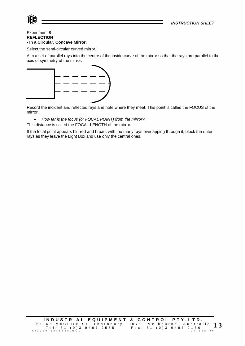
Experiment 8REFLECTION- In a Circular, Concave Mirror.Select the semi-circular curved mirror.Aim a set of parallel rays into the centre of the inside curve of the mirror so that the rays are parallel to theaxis of symmetry of the mirror.
Record the incident and reflected rays and note where they meet. This point is called the FOCUS of themirror.
• How far is the focus (or FOCAL POINT) from the mirror?This distance is called the FOCAL LENGTH of the mirror.If the focal point appears blurred and broad, with too many rays overlapping through it, block the outerrays as they leave the Light Box and use only the central ones.

INSTRUCTION SHEET
I N D U S T R I A L E Q U I P M E N T & C O N T R O L P T Y . L T D .6 1 - 6 5 M c C l u r e S t . T h o r n b u r y . 3 0 7 1 M e l b o u r n e . A u s t r a l i a
T e l : 6 1 ( 0 ) 3 9 4 9 7 2 5 5 5 F a x : 6 1 ( 0 ) 3 9 4 9 7 2 1 6 6h l 2 0 6 0 - 0 0 1 b o o k . D O C 2 7 - J u n - 0 6
1 4
Experiment 9REFLECTION- Centre of Curvature- Radius of Curvature- Focal Length of a Circular MirrorSet up as in the last experiment and, on paper, trace the inside reflecting surface of the concave mirror.Move the mirror around the curve and continue tracing until you have a complete circle.Measure the diameter of this circle in several directions and calculate an average diameter.
• What is the radius of the circle?Find the centre of curvature, i.e. the centre of the circle.
• How does the radius compare with the focal length you found in the last experiment? Another method of finding the centre of curvature is to aim a single ray at the inside curve of the mirror sothat it reflects straight back on itself. To do this, the ray must be meeting the surface along its ”normal” ormust be perpendicular to the surface at that point and must be reflected back along this radius positionthrough the centre of curvature. Record this ray position and without moving the mirror, move the ray boxto another position where the ray again reflects back on itself and record the new ray position. Repeat thisprocedure a third time.The point where the rays meet is the CENTRE OF CURVATURE and the distance from this point to thecurve of the mirror is the RADIUS OF CURVATURE.

INSTRUCTION SHEET
I N D U S T R I A L E Q U I P M E N T & C O N T R O L P T Y . L T D .6 1 - 6 5 M c C l u r e S t . T h o r n b u r y . 3 0 7 1 M e l b o u r n e . A u s t r a l i a
T e l : 6 1 ( 0 ) 3 9 4 9 7 2 5 5 5 F a x : 6 1 ( 0 ) 3 9 4 9 7 2 1 6 6h l 2 0 6 0 - 0 0 1 b o o k . D O C 2 7 - J u n - 0 6
1 5
Experiment 10.REFLECTION- Circular Aberration.
• What happens when parallel rays are directed at a circular mirror PARALLEL to the axis ofsymmetry but displaced sideways?
Use only two rays from the Light Box.Record six positions of the focal point as you move the ray box to different positions, keeping the raysparallel to the axis of symmetry.
• Do the various focal points lie on a curve or on a straight line?• When four rays which are parallel to the axis of symmetry of the mirror are focused do they really
focus at one point?Using a four slit former, block the inner two rays and record the position of the outer two rays and theirfocal point. Mark the mirror position.Block the outer two rays and record the inner two rays and their focal point.
• Which rays focus nearer to the mirror - the inner rays or the outer rays?Using another sheet of paper, repeat the outer and inner ray tracing, with four rays PARALLEL to the axisof symmetry but displaced sideways.
• Is the circular aberration (i.e. failure for all rays to focus at one point) increased or decreased byshifting the rays to one side of the axis of symmetry?
Remove the slit-former from the Light Box and adjust the collimating lens to project a diverging beam.Hold the Light Box above the table and move it about one metre away. Project this wide beam into themirror at a slight downward angle and observe the brightly illuminated area. Outline this area.This shape is called a CAUSTIC CURVE. Caustic means burning.
• Why is a magnifying glass often called a burning glass?• What causes the shape of this caustic curve?
Slide the single slit-former sideways across the face of the Light Box so that the wide beam is graduallycut offDetermine to where each part of the beam is reflected.A shape like the caustic curve, which is the outline of the limiting positions of a movable or flexible line, issometimes called an ”envelope”. You will meet more envelopes in higher mathematics and find theequations that generate them.On one of your records of reflections, draw lines from the centre of curvature to the points of reflection.Each of these new lines is a radius and is normal to the mirror curve.For each reflection, mark the angle of incidence (between the incident ray and the normal) and the angleof reflection (between the reflected ray and the normal).Does each angle of incidence equal the accompanying angle of reflection?

INSTRUCTION SHEET
I N D U S T R I A L E Q U I P M E N T & C O N T R O L P T Y . L T D .6 1 - 6 5 M c C l u r e S t . T h o r n b u r y . 3 0 7 1 M e l b o u r n e . A u s t r a l i a
T e l : 6 1 ( 0 ) 3 9 4 9 7 2 5 5 5 F a x : 6 1 ( 0 ) 3 9 4 9 7 2 1 6 6h l 2 0 6 0 - 0 0 1 b o o k . D O C 2 7 - J u n - 0 6
1 6
Experiment 11REFLECTION- Convex MirrorProject a number of parallel rays to strike the OUTSIDE surface of the semi circular mirror, parallel to itsaxis.Record the mirror position and ray paths and indicate the ray directions with arrow heads.
• Where do the diverging rays appear to come from?Locate this point by drawing the diverging rays backwards through the mirror position. The point theycome from is called the VIRTUAL FOCUS and the distance of this point from the mirror is called theVIRTUAL FOCAL LENGTH.
• How does this focal length compare with the focal length of the concave side of the mirror?• How does it compare with the radius of curvature of the mirror found previously?• By how much do the results differ?• Can this amount be related to the mirror construction?• Suggest why slightly convex mirrors are used as rear vision mirrors in cars.
If a line is drawn from the centre of curvature through the point where a ray strikes the mirror, this line isnormal to the surface. Draw several of these normals.For each reflection, measure the angle of incidence (between the incident ray and the normal) and theangle of reflection (between the reflected ray and the normal)
• For each reflection, does the angle of incidence equal the accompanying angle of reflection?
Experiment 12REFLECTION- Parabolic ReflectorA parabola is an unusually shaped curve which is found by one of the following methods -
• Plot a graph of y = x2 or some other quadratic algebraic function.• Record the flight of a projectile through the air.• Move a point P so that it is always a relative distance from a fixed point F (called the FOCUS) and
a straight line AB. This line is called the DIRECTRIX because it directs which way the parabolawill face.
Printwize..... this is the wrong pic. See book for correct pic.

INSTRUCTION SHEET
I N D U S T R I A L E Q U I P M E N T & C O N T R O L P T Y . L T D .6 1 - 6 5 M c C l u r e S t . T h o r n b u r y . 3 0 7 1 M e l b o u r n e . A u s t r a l i a
T e l : 6 1 ( 0 ) 3 9 4 9 7 2 5 5 5 F a x : 6 1 ( 0 ) 3 9 4 9 7 2 1 6 6h l 2 0 6 0 - 0 0 1 b o o k . D O C 2 7 - J u n - 0 6
1 7
• Cut a cone in a plane parallel to the sloping side. This is called making a CONIC SECTION. Otherconic sections are circles, ellipses, or hyperbolas.
• How are these made?
Aim a set of parallel rays into a parabolic reflector along paths parallel to the axis of symmetry of themirror.Record the mirror position and ray paths.Record the focal length.
Move the Light Box sideways keeping the rays parallel to the axis of symmetry. Graph paper is useful toalign the mirror and ray paths to ensure the rays are parallel to the axis.
• What do you notice about the position of the focal point?

INSTRUCTION SHEET
I N D U S T R I A L E Q U I P M E N T & C O N T R O L P T Y . L T D .6 1 - 6 5 M c C l u r e S t . T h o r n b u r y . 3 0 7 1 M e l b o u r n e . A u s t r a l i a
T e l : 6 1 ( 0 ) 3 9 4 9 7 2 5 5 5 F a x : 6 1 ( 0 ) 3 9 4 9 7 2 1 6 6h l 2 0 6 0 - 0 0 1 b o o k . D O C 2 7 - J u n - 0 6
1 8
Aim a broad parallel sided beam of light into the parabolic mirror and observe the effect.
• What shaped mirror would be used to produce sharp images of stars scattered in all directionsover the field of view?
• What would happen if a point source of light (a torch globe) is placed at the focal point of aparabolic mirror? Try it and see.
• Why do radar antennae, radio-telescopes, car head lamp reflectors and radiator reflectors, have aparabolic shape rather than a spherical or circular shape?
• In the examples given, where in relation to the reflector, would the receiving, transmitting orradiating device be placed?
Suggest why this is so.

INSTRUCTION SHEET
I N D U S T R I A L E Q U I P M E N T & C O N T R O L P T Y . L T D .6 1 - 6 5 M c C l u r e S t . T h o r n b u r y . 3 0 7 1 M e l b o u r n e . A u s t r a l i a
T e l : 6 1 ( 0 ) 3 9 4 9 7 2 5 5 5 F a x : 6 1 ( 0 ) 3 9 4 9 7 2 1 6 6h l 2 0 6 0 - 0 0 1 b o o k . D O C 2 7 - J u n - 0 6
1 9
Chapter 2 REFRACTIONExperiment 13REFRACTION- Semi Circular BlockAim a single beam at an angle of 90o at the centre point of the flat side of the semi circular block.
Record the block position and the ray path.
• Is there any deflection in the beam?If there is, the angle is not 90o.Move the Light Box so that the ray strikes the same central point on the flat side of the block, but at anangle of 10o to the normal.
Record the ray path into and out of the block, so that when the block is removed the ray path through itcan be clearly seen.Move the Light Box several times and using coloured pencils record with different colours the new raypaths (all entering the same place on the block).What happens when a light ray:-
• Passes from one medium (air) to another medium (acrylic plastic) at an angle of 90o?• Passes as before, but at an angle of not 90o? (i.e. the angle of incidence is not zero).• Passes from the acrylic plastic back into the air?• Why does no bending (refraction) occur as the ray passes through the semi circular face while it
does bend (refract) passing through the flat face?Remove the block after making about six rays and mark the position of the flat side of the block. (Rayscan be used on both sides of the normal to the flat surface.)Carefully draw all the rays meeting at the mid point of the flat side and their subsequent paths.Draw a 100 mm diameter circle where the centre is the point of incidence. Carefully extend the incidentand refracted rays to intersect the circle. Draw the normal N to the incident surface, through the point ofincidence.Draw perpendiculars to the normal line from where the rays and circle intercept.

INSTRUCTION SHEET
I N D U S T R I A L E Q U I P M E N T & C O N T R O L P T Y . L T D .6 1 - 6 5 M c C l u r e S t . T h o r n b u r y . 3 0 7 1 M e l b o u r n e . A u s t r a l i a
T e l : 6 1 ( 0 ) 3 9 4 9 7 2 5 5 5 F a x : 6 1 ( 0 ) 3 9 4 9 7 2 1 6 6h l 2 0 6 0 - 0 0 1 b o o k . D O C 2 7 - J u n - 0 6
2 0
Your diagram should look like this:-
These last perpendiculars are called HALF CHORDS.Compile a table of observations as follows:
RAY # ANGLE OFINCIDENCE
i
ANGLE OFREFRACTION
r
DIFFERENCEBETWEENANGLES
i-r
RATIO OF ir
LENGTHOF HALFCHORD
i
LENGTH OFHALF CORD
r
1.
2.
3.
4.
5.
6.
RAY #RATIO OF: HALF CHORD i
HALF CHORD r SIN i SIN rRATIO OF: SIN i
SIN r
1.
2.
3.
4.
5.
6.

INSTRUCTION SHEET
I N D U S T R I A L E Q U I P M E N T & C O N T R O L P T Y . L T D .6 1 - 6 5 M c C l u r e S t . T h o r n b u r y . 3 0 7 1 M e l b o u r n e . A u s t r a l i a
T e l : 6 1 ( 0 ) 3 9 4 9 7 2 5 5 5 F a x : 6 1 ( 0 ) 3 9 4 9 7 2 1 6 6h l 2 0 6 0 - 0 0 1 b o o k . D O C 2 7 - J u n - 0 6
2 1
If you have not studied TRIGONOMETRY or LOGARITHMS, you may not know how to fill in the last threecolumns, but this does not matter. They are simply a more accurate way of checking the answersobtained in the fourth last column.
• Is the difference between angle i and angle r always the same?• Is the ratio of: angle i always the same?
angle r
• Is the ratio of: half chord i always approximately the same? half chord r
• Is the ratio of: sin i always the same? sin r

INSTRUCTION SHEET
I N D U S T R I A L E Q U I P M E N T & C O N T R O L P T Y . L T D .6 1 - 6 5 M c C l u r e S t . T h o r n b u r y . 3 0 7 1 M e l b o u r n e . A u s t r a l i a
T e l : 6 1 ( 0 ) 3 9 4 9 7 2 5 5 5 F a x : 6 1 ( 0 ) 3 9 4 9 7 2 1 6 6h l 2 0 6 0 - 0 0 1 b o o k . D O C 2 7 - J u n - 0 6
2 2
The man who discovered this phenomenon was named Snell. Snell’s Law states:-* When a light ray passes from one medium (material) to another medium at an angle (not perpendicularto their interface), it undergoes bending (REFRACTION)and the ratio of: sin i (or the ratio of the half chords) is a constant for these two particular media. sin r
* The incident ray, the normal to the interface and the refracted ray, lie on one plane (i.e. they are calledCO-PLANAR).The ratio of: sin i (or the ratio of the half chords) is a called sin r
the REFRACTIVE INDEX for the two materials.
• What is the refractive index for an AIR-ACRYLIC Plastic interface?To observe and record the different bending properties (different REFRACTIVE INDICES) of materialsother than acrylic, use either a glass block in place of the acrylic block, or use a shallow semi circularplastic tray partly filled with water, kerosene, paraffin, or other clear liquid.Disregard what eventually happens to the rays but record only the first interface bending.

INSTRUCTION SHEET
I N D U S T R I A L E Q U I P M E N T & C O N T R O L P T Y . L T D .6 1 - 6 5 M c C l u r e S t . T h o r n b u r y . 3 0 7 1 M e l b o u r n e . A u s t r a l i a
T e l : 6 1 ( 0 ) 3 9 4 9 7 2 5 5 5 F a x : 6 1 ( 0 ) 3 9 4 9 7 2 1 6 6h l 2 0 6 0 - 0 0 1 b o o k . D O C 2 7 - J u n - 0 6
2 3
Experiment 14REFRACTION- Parallel Sided BlockPlace the rectangular block with the long side perpendicular to a single beam.
• Is there any refraction at either incident or emergent faces? If not, why not?• The ray passes from one medium (air) into a second medium (acrylic plastic) at the first interface
and vice versa at the second interface. Therefore what other condition, besides a ray passingfrom one medium to another, must be present for refraction to occur?
Move the Light Box until the ray hits the centre of the long side of the block at an angle of incidence of 10o.
This is at 80o to the surface. Record the incident and emergent paths. Remove the block and draw:(a) The ray path through the block.(b) The theoretical ray path which would have been followed if no block had been in position.
• Is the emergent ray parallel to the incident ray and its extension?Now draw the normals to the interface where the rays entered and emerged from the block.Measure the angles of incidence and refraction (from the normals) at both interfaces. Draw arrows on theray if you have doubt as to which is the incident ray at the second interface.Using a protractor, measure and label the angles of incidence and the angles of refraction of the tworefractions.
• Is the amount of refraction at the first interface reversed at the second face?Draw circles, as in EXPERIMENT 13, around each point of refraction and draw and measure half chordsto the normals at these points.

INSTRUCTION SHEET
I N D U S T R I A L E Q U I P M E N T & C O N T R O L P T Y . L T D .6 1 - 6 5 M c C l u r e S t . T h o r n b u r y . 3 0 7 1 M e l b o u r n e . A u s t r a l i a
T e l : 6 1 ( 0 ) 3 9 4 9 7 2 5 5 5 F a x : 6 1 ( 0 ) 3 9 4 9 7 2 1 6 6h l 2 0 6 0 - 0 0 1 b o o k . D O C 2 7 - J u n - 0 6
2 4
Using the formula: Refractive index = sin i or half chord i find the sin r half chord r
refractive index from air to acrylic and the refractive index from acrylic to air.• Which is greater than 1? Which is less than 1?• Is one the inverse of the other?• If the refractive index from air to glass is 1.5, (i.e. 3/2), what is the refractive index from glass to
air?• If the refractive index from air to water is 1.33, (i.e. 4/3), what is the refractive index from water to
air?Only one angle of incidence (about 10o) has been used to find the refractive index.
• Is there any need to use any other angle of incidence? If not, why not?

INSTRUCTION SHEET
I N D U S T R I A L E Q U I P M E N T & C O N T R O L P T Y . L T D .6 1 - 6 5 M c C l u r e S t . T h o r n b u r y . 3 0 7 1 M e l b o u r n e . A u s t r a l i a
T e l : 6 1 ( 0 ) 3 9 4 9 7 2 5 5 5 F a x : 6 1 ( 0 ) 3 9 4 9 7 2 1 6 6h l 2 0 6 0 - 0 0 1 b o o k . D O C 2 7 - J u n - 0 6
2 5
Experiment 15REFRACTION- Total Internal ReflectionUsing the Semi-Circular BlockArrange the semi circular block so that a single light ray strikes the curved surface at its normal mid-pointand passes through the Centre of the flat side.
• Is there any refraction at either interface? If not, why not?Mark the position of the centre of the straight side of block and rotate the block slightly about this pointuntil the ray inside the block meets the flat side at an angle.
• Is the ray at this flat face refracted towards or away from the normal at the point of incidence?Again rotate the block about the centre point of the flat side and observe and record the emergent ray atthe new position.Continue this rotation of the block until no refracted ray emerges from the flat face.
• What is the angle of incidence at the flat face when this occurs?Rotate the block a little further.
• What happens to the ray that was previously refracted? Rotate it back again until the ray ceasesto be internally reflected and is again refracted.
Once again find the angle of incidence at which refraction ceases and INTERNAL REFLECTIONcommences.Measure this angle of incidence which is called the CRITICAL ANGLE for this material.The definition is: The critical angle for a material is the angle of incidence beyond which a light ray,passing from a dense to a light medium is no longer refracted out of the medium but is totally internallyreflected.Draw a circle of approximately 100 mm radius about the incident point and record the half chords of thecritical angle (called ic).
Calculate the ratio of: half chord of ic or find sin ic from a book of mathematical tables. radius
Using your previous experimental results,
calculate: 1 .
refractive index for acrylic to air

INSTRUCTION SHEET
I N D U S T R I A L E Q U I P M E N T & C O N T R O L P T Y . L T D .6 1 - 6 5 M c C l u r e S t . T h o r n b u r y . 3 0 7 1 M e l b o u r n e . A u s t r a l i a
T e l : 6 1 ( 0 ) 3 9 4 9 7 2 5 5 5 F a x : 6 1 ( 0 ) 3 9 4 9 7 2 1 6 6h l 2 0 6 0 - 0 0 1 b o o k . D O C 2 7 - J u n - 0 6
2 6
What do you notice about:
half chord of ic : sin ic : : 1 .
radius refractive index for acrylic to air
• If the refractive index from air to glass is 1.5, (i.e. 3/2), what is its inverse?• What then does sin ic equal from glass to air?• What then is the critical angle from glass to air?• If the refractive index from air to water is 1.33, (i.e. 4/3), what is its inverse?• What then is the critical angle from water to air?
If possible, take a block of glass and a shallow tray of water and project a single ray through them in turn.Find and check the critical angles for glass to air and water to air.
• If a glass block is placed in water and the glass to water interface observed, should the criticalangle occur when the ray passes from water to glass, or glass to water?
Check your answer experimentally.
• How is the critical angle of a piece of acrylic plastic used to find its refractive index?

INSTRUCTION SHEET
I N D U S T R I A L E Q U I P M E N T & C O N T R O L P T Y . L T D .6 1 - 6 5 M c C l u r e S t . T h o r n b u r y . 3 0 7 1 M e l b o u r n e . A u s t r a l i a
T e l : 6 1 ( 0 ) 3 9 4 9 7 2 5 5 5 F a x : 6 1 ( 0 ) 3 9 4 9 7 2 1 6 6h l 2 0 6 0 - 0 0 1 b o o k . D O C 2 7 - J u n - 0 6
2 7
Experiment 1 6REFRACTION- Total Internal ReflectionUsing Triangular Prisms(a) Aim a single beam of light at the shortest side of the 30o-60o-90o acrylic prism, so that the refractedbeam inside the prism strikes the hypotenuse.Adjust the Light Box and prism positions until total internal reflection occurs and the ray emerges throughthe third side.
Record the first position at which this occurs and measure the angle of incidence from the normal to thehypotenuse.
• Is it the same as the critical angle in the last experiment?(b) Aim the single beam perpendicularly into the shorter side of the 45o-45o-90o acrylic prism so that theray strikes the hypotenuse internally.
• Is it reflected?Record the entrant and emergent rays and the prism position.Aim a single ray perpendicular to the hypotenuse of the 45o prism at about a quarter the distance from oneend.
This time the ray is totally reflected internally in the prism twice and returns on a path that is parallel to itsoriginal one but reversed in direction.Trace the prism position and the ray path through it.(c) Aim four parallel rays into the 45o prism hypotenuse near one end, colour the rays in turn (by placinga colour filter over them) and trace the path of each ray in different colours.
• Are the ray positions reversed by the double reflections?(d) Aim two parallel beams into two 45o prisms, placed as in the diagram.

INSTRUCTION SHEET
I N D U S T R I A L E Q U I P M E N T & C O N T R O L P T Y . L T D .6 1 - 6 5 M c C l u r e S t . T h o r n b u r y . 3 0 7 1 M e l b o u r n e . A u s t r a l i a
T e l : 6 1 ( 0 ) 3 9 4 9 7 2 5 5 5 F a x : 6 1 ( 0 ) 3 9 4 9 7 2 1 6 6h l 2 0 6 0 - 0 0 1 b o o k . D O C 2 7 - J u n - 0 6
2 8
Colour each beam in turn and trace its path.
• Does the quadruple reflection (twice in each prism) restore the beams to their original relationship,or are they still reversed?
Pairs of prisms arranged in such a manner are used in prismatic binoculars, to shorten the overall lengthof what would otherwise be a 0.5 metre to 0.75 metre long telescope.

INSTRUCTION SHEET
I N D U S T R I A L E Q U I P M E N T & C O N T R O L P T Y . L T D .6 1 - 6 5 M c C l u r e S t . T h o r n b u r y . 3 0 7 1 M e l b o u r n e . A u s t r a l i a
T e l : 6 1 ( 0 ) 3 9 4 9 7 2 5 5 5 F a x : 6 1 ( 0 ) 3 9 4 9 7 2 1 6 6h l 2 0 6 0 - 0 0 1 b o o k . D O C 2 7 - J u n - 0 6
2 9
Experiment 17REFRACTION- Double Refraction Angle of Minimum DeviationAim a single ray of light into one face of the equilateral triangular prism (60o-60o-60o) so that the beam isapproximately parallel to an adjacent side and the ray emerges from the third side after being refractedtwice.
Record the prism position and the light ray paths.Aim the ray at the same spot on the prism face and alter the angle of incidence. Observe the alteration inthe direction of the emergent ray.Find the position of the prism and light ray which produces the minimum deviation of the beam from itsoriginal to its final direction.Repeat this experiment using the 45o angle at position A and find the angle of minimum deviation.Repeat this experiment using the 90o angle at position A and find the angle of minimum deviationRepeat this experiment using a 30o angle at position A and find the angle of minimum deviation.Tabulate your observations as follows:
RAY ANGLE OFINCIDENCE
ANGLE OF MINIMUMDEVIATION
A
B
C
• How does the angle of the prism affect the angle of minimum deviation?• What happens when the 90’ angle is used in position A?
INSTRUCTION SHEET
I N D U S T R I A L E Q U I P M E N T & C O N T R O L P T Y . L T D .6 1 - 6 5 M c C l u r e S t . T h o r n b u r y . 3 0 7 1 M e l b o u r n e . A u s t r a l i a
T e l : 6 1 ( 0 ) 3 9 4 9 7 2 5 5 5 F a x : 6 1 ( 0 ) 3 9 4 9 7 2 1 6 6h l 2 0 6 0 - 0 0 1 b o o k . D O C 2 7 - J u n - 0 6
3 0
Experiment 18REFRACTION- Double Refraction Using Parallel Rays(a) As in the previous experiment, aim a single ray through a triangular prism. Regard the apex angle ofthe prism as angle A and the side opposite A as its base.
• Does the doubly refracted ray bend towards or away from the base?Repeat this experiment, using each angle of each prism at angle A in turn.
• Is the direction of bending towards the base the same for any angle at position A?(b) Aim a pair of parallel beams through each of the triangular prisms in turn and observe the emergentrays.
• Do the parallel rays emerge parallel to each other for each of the three prism angles of 30o, 45o
and 60o?
Experiment 19REFRACTION- Double RefractionUsing Colour DispersionFit the slit former that gives the wide beam. Aim single wide beam through the equilateral prism and adjustthe prism so that the maximum deflection of the ray is obtained. Place a white card in the path of the ray.
• Is the original beam from the Light Box white or coloured?• Does the emergent beam have any indication of colour?• Which edge of the beam is red and which is blue?
If more colours than red and blue are present, make a list of the order in which they appear.Such a spread of colours, caused by the dispersion of white light is called a SPECTRUM. It is causedbecause each colour bends a slightly different amount during diffraction. All colours together make whitelight and a prism can separate them again because of this amazing phenomenon.

INSTRUCTION SHEET
I N D U S T R I A L E Q U I P M E N T & C O N T R O L P T Y . L T D .6 1 - 6 5 M c C l u r e S t . T h o r n b u r y . 3 0 7 1 M e l b o u r n e . A u s t r a l i a
T e l : 6 1 ( 0 ) 3 9 4 9 7 2 5 5 5 F a x : 6 1 ( 0 ) 3 9 4 9 7 2 1 6 6h l 2 0 6 0 - 0 0 1 b o o k . D O C 2 7 - J u n - 0 6
3 1
Experiment 20REFRACTION- Colour Absorption by FiltersWith the apparatus set up as in the previous experiment, place a red filter in the wide groove of the LightBox in front of the wide beam slit former plate.
• What effect has this on the emergent spectrum?Remove the filter from between the light source and the dispersing prism. Now place the filter so that thecolour dispersed beam emerging from the prism passes through the filter.
• What happens to the colours which are NOT red?Repeat this procedure, using the other filters in the kit. Firstly do this one by one then try various pairs.Copy and complete the following table by placing ticks and crosses in the appropriate boxes.
WHITE LIGHT CONTAINS THESE COLOURS
RED VIOLET
TRANSMITSRED FILTER ABSORBS
TRANSMITSBLUE FILTER ABSORBS
TRANSMITSYELLOW FILTER ABSORBS
TRANSMITS? FILTER ABSORBS
ETC.Experiment 21REFRACTION- Newton’s Experiment with SpectraProduce a clear spectrum using the colour dispersion caused by double refraction through a single prismof 60’ included angle set at the position of minimum deviation. Use a narrow ray.
Perform Sir Isaac Newton’s experiment by placing a second 60o prism in the path of the colour dispersedbeam. Be sure that the faces of the two prisms are parallel and very close together.This refracts the beam again in the opposite direction and recombines the colours of the spectrum tomake white light.When a disc on which a set of all the spectrum colours is painted is spun rapidly, the eye sees only a blurof all the colours and the disc appears to be white.Ask your teacher to demonstrate a ”Newton’s Colour Disc”.

INSTRUCTION SHEET
I N D U S T R I A L E Q U I P M E N T & C O N T R O L P T Y . L T D .6 1 - 6 5 M c C l u r e S t . T h o r n b u r y . 3 0 7 1 M e l b o u r n e . A u s t r a l i a
T e l : 6 1 ( 0 ) 3 9 4 9 7 2 5 5 5 F a x : 6 1 ( 0 ) 3 9 4 9 7 2 1 6 6h l 2 0 6 0 - 0 0 1 b o o k . D O C 2 7 - J u n - 0 6
3 2
Experiment 22REFRACTION- Double Refraction Using Bi-Convex LensEXPERIMENT 18 demonstrated that a single prism will not bring parallel rays to a focus - they remainparallel after refraction, although showing a little colour dispersion.Sets of prisms, however, can be used to focus what were parallel rays, to meet at a point.Set the Light Box to produce two parallel rays as widely spaced as possible.
Place prisms with 60o and 30o angles as shown in the diagram, and trace the path of the emergent rays.Rearrange the prisms as shown in the diagram below, this time using two identical prisms. (Borrow onefrom another set.)This method of placement focuses two parallel beams A and B to the one point.
• If another beam parallel to beam A and one parallel to beam B are added, do they also focus atthe same spot? Try it and see.
• To bring ALL rays to a focus at one point, another prism with a different angle for ray C and yet anotherwith different angle for ray D is required. This means that a prism is needed where the angle iscontinuously changing from a small angle to a large angle. Such an object is called a LENS.

INSTRUCTION SHEET
I N D U S T R I A L E Q U I P M E N T & C O N T R O L P T Y . L T D .6 1 - 6 5 M c C l u r e S t . T h o r n b u r y . 3 0 7 1 M e l b o u r n e . A u s t r a l i a
T e l : 6 1 ( 0 ) 3 9 4 9 7 2 5 5 5 F a x : 6 1 ( 0 ) 3 9 4 9 7 2 1 6 6h l 2 0 6 0 - 0 0 1 b o o k . D O C 2 7 - J u n - 0 6
3 3
Aim four parallel rays into one face of the thinner of the two lenses of the kit as shown in the diagrambelow. Record the lens position, the ray paths and the focal point.
• If the FOCAL LENGTH of a lens is the distance from the LENS-CENTRE to the FOCAL POINT,what is the focal length of this lens?
On a separate piece of paper, find the focal length of the thicker lens of similar shape in the kit.
Lenses of this shape are called BI-CONVEX because both sides bulge outwards.
Experiment 23REFRACTION- Radius of CurvatureTrace the curve of one side of the thinner lens surface on your sheet of paper.Move the curved surface along this tracing and extend the tracing a number of times until it forms a circle.Measure the diameter of the circle and calculate the radius.Repeat the experiment, using the thicker bi-convex lens.
• What is the radius of the second circle?Each of the radius of the circles is called the RADIUS OF CURVATURE of the particular lens used todraw the circle.Using the results obtained in EXPERIMENT 22, compare the radius of curvature of each lens with its focallength.
• How does radius of curvature affect focal length?• If a lens with a focal length of 20 mm is required, what radius of curvature should be used.
The curvature of a lens does not necessarily need to be the same for both sides.

INSTRUCTION SHEET
I N D U S T R I A L E Q U I P M E N T & C O N T R O L P T Y . L T D .6 1 - 6 5 M c C l u r e S t . T h o r n b u r y . 3 0 7 1 M e l b o u r n e . A u s t r a l i a
T e l : 6 1 ( 0 ) 3 9 4 9 7 2 5 5 5 F a x : 6 1 ( 0 ) 3 9 4 9 7 2 1 6 6h l 2 0 6 0 - 0 0 1 b o o k . D O C 2 7 - J u n - 0 6
3 4
A lens may be the same shape as those in the kit, although many are shaped in a similar manner to thoseshown in the diagram above. The curvature on one side may not be the same on the other side and oneside can be convex (bulging out) while the other side is concave (bulging inwards).The following formula shows the relationship between refractive index, focal length and radius ofcurvature:
Where:-t - focal length of lensn - refractive index of the materialR1 - radius of curvature of one faceR2 - radius of curvature of the other face
• What are the Values of R1 and R2 for the two bi-convex lenses in the kit? Use one of these sets of values in the above formula and calculate the value of ‘n’ for the plastic
material in the lenses.
• Use the second set of values to verify the value of ‘n’ for this material. (Both lenses are made ofthe same material).
How does the value of ‘n’ you have calculated compare with the value you obtained inEXPERIMENT 13?

INSTRUCTION SHEET
I N D U S T R I A L E Q U I P M E N T & C O N T R O L P T Y . L T D .6 1 - 6 5 M c C l u r e S t . T h o r n b u r y . 3 0 7 1 M e l b o u r n e . A u s t r a l i a
T e l : 6 1 ( 0 ) 3 9 4 9 7 2 5 5 5 F a x : 6 1 ( 0 ) 3 9 4 9 7 2 1 6 6h l 2 0 6 0 - 0 0 1 b o o k . D O C 2 7 - J u n - 0 6
3 5
Experiment 24REFRACTION- Focal Line or Focal Plane of a Bi-Convex LensPlace one of the bi-convex lenses on a sheet of paper and trace its outline.Without altering the lens position, arrange the Light Box to project two parallel rays and move it so that it –(a) Projects the rays parallel to the axis of symmetry of the lens.(b) Projects the rays at a small angle to the axis but aimed at the centre of the lens; first from the left hand side and then from the right hand side.(c) Projects the rays at larger angles from the axis, but still aimed at the lens centre.Draw a line through this series of focal points (FOCI).
• Do the points form a straight or curved line?• If we assume that the pairs of parallel rays are coming from distant stars and passing through the
lens, where should a photographic film be placed so that the star images are in focus?The position at which parallel rays from any angle come to a focus is called the FOCAL PLANE of thelens.Some cameras have a shutter which opens and closes near the lens. Others (which have removable orinterchangeable lenses) have a shutter like a roller-blind which covers the film, except for the instant whenthe blind rolls up to make the exposure. Such a shutter is called a FOCAL PLANE shutter.
Experiment 25REFRACTION- Chromatic Aberration by Bi-Convex LensPass rays through the outer edges of a bi-convex lens.Observe that they have coloured edges after refraction.
• Which edge is red and which blue?Pass two parallel rays through the outer edges of the lens so that they come to a focus.Place a vertical white card near the point of focus and move it to and from the lens.
• In what position from the lens is the card placed when the image on the card has a reddish centreand blue edges?
Suggest why cheap toy telescopes and binoculars have colour fringes around the images they produce.Makers of lenses for cameras, telescopes, etc. go to great trouble using combinations of lenses ofdifferent curvatures and made from glasses of different refractive indices, to ensure that all colours cometo a focus at the same point. A lens combination which has elements designed to do this is called anACHROMATIC LENS.

INSTRUCTION SHEET
I N D U S T R I A L E Q U I P M E N T & C O N T R O L P T Y . L T D .6 1 - 6 5 M c C l u r e S t . T h o r n b u r y . 3 0 7 1 M e l b o u r n e . A u s t r a l i a
T e l : 6 1 ( 0 ) 3 9 4 9 7 2 5 5 5 F a x : 6 1 ( 0 ) 3 9 4 9 7 2 1 6 6h l 2 0 6 0 - 0 0 1 b o o k . D O C 2 7 - J u n - 0 6
3 6
Experiment 26REFRACTION- Bi-Concave LensSelect the lens which has two hollow sides curving in towards each other, making it thinner at the centrethan at the sides. This is called a BI-CONCAVE lens.Aim four parallel rays of light at the lens, parallel to its axis of symmetry.Trace the lens position and both the entrant and emergent rays.Remove the lens and extend the emergent rays back through the lens position towards the Light Box.
• Do they appear to radiate from one point, or from several?A bi-concave lens is a DIVERGING LENS and is said to have a NEGATIVE FOCAL LENGTH because thepoint from which the rays appear to emerge is not beyond the lens but between the light source and thelens.
• What is the focal length of the lens used?Such lenses are useful in correcting short-sightedness. This is a condition in which the image formed bythe lens of the eye falls short of the light sensitive retina.
They are also used to increase the focal length of converging lenses.Try to remember the method that was suggested at the beginning of this manual to give a long convergingbeam from the Light Box?

INSTRUCTION SHEET
I N D U S T R I A L E Q U I P M E N T & C O N T R O L P T Y . L T D .6 1 - 6 5 M c C l u r e S t . T h o r n b u r y . 3 0 7 1 M e l b o u r n e . A u s t r a l i a
T e l : 6 1 ( 0 ) 3 9 4 9 7 2 5 5 5 F a x : 6 1 ( 0 ) 3 9 4 9 7 2 1 6 6h l 2 0 6 0 - 0 0 1 b o o k . D O C 2 7 - J u n - 0 6
3 7
Chapter 3 COLOUR OBSERVATIONSExperiment 27COLOUR OBSERVATION- Colours of ObjectsIn CHAPTER 2, EXPERIMENT 20, white light was dispersed into a rainbow coloured spectrum bypassing it through a prism. Various filters are placed in the beam to see which of the rainbow colours aretransmitted by the filters and which are absorbed.The rear end of the Light Box has swinging mirrors and is designed to carry colour filters in 3 positions.Using the rear end of the Light Box (not the mirrors) direct a beam of white light on to each of the eightcoloured plates in the kit. Colour the incident beam by sliding filters into the grooves provided and recordthe observed colours of the plated when illuminated by different coloured beams. Copy and complete thetable shown below.The colour of an object is explained by stating that white light is composed of many colours and that awhite object reflects all these colours.A red object absorbs all the colours except red, which it reflects, making the object appear red.If however, the red is completely filtered from the incident light by using a blue-green (or cyan) filter, thenthe red object should absorb the incident cyan colour and should reflect nothing. Check your tabulatedobservations against this theory.Familiarise yourself with the coloured filters and plates and predict how the following colours shouldappear –A blue object, illuminated by red and seen with the naked eye.A red object, illuminated by orange and seen through a yellow filter.A blue object, illuminated by red and seen through a yellow filter.A red object, illuminated by orange and seen with the naked eye.A red object, illuminated by orange and seen through a blue filter, etc., etc.
COLOUR OFOBJECT IN
COLOUR OF OBJECT WHEN INCIDENT LIGHT ON OBJECT IS:
WHITE LIGHT RED ORANGE YELLOW GREEN BLUE VIOLETRED
ORANGEYELLOWGREENBLUE
VIOLETllluminate the various plates with white light, and holding the filter close to your eye, observe the plates.Copy and complete the following table.
COLOUR OFOBJECT IN
COLOUR OF OBJECT WHEN VIEWED THROUGH A FILTER OF COLOUR
WHITE LIGHT RED ORANGE YELLOW GREEN BLUE VIOLETRED
ORANGEYELLOWGREENBLUE
VIOLET

INSTRUCTION SHEET
I N D U S T R I A L E Q U I P M E N T & C O N T R O L P T Y . L T D .6 1 - 6 5 M c C l u r e S t . T h o r n b u r y . 3 0 7 1 M e l b o u r n e . A u s t r a l i a
T e l : 6 1 ( 0 ) 3 9 4 9 7 2 5 5 5 F a x : 6 1 ( 0 ) 3 9 4 9 7 2 1 6 6h l 2 0 6 0 - 0 0 1 b o o k . D O C 2 7 - J u n - 0 6
3 8
Experiment 28COLOUR OBSERVATIONS- Addition of ColoursUsing the 2 side positions with mirrors and also the end position of the Light Box, project three colouredbeams on to a white card. Make the first set of colours red, blue and yellow.NOTE: Place the weakest colour in the end position of the Light Box and the stronger colours at the sides.This compensates for the small loss of intensity during reflection from the side mirrors. To blank off oneof the openings, use the blank slit former (the end without slits).Move the mirrors to use the beams to overlap and record your observations in tabulated form as follows:RED + BLUE gives....RED + YELLOW gives....YELLOW + BLUE gives....RED + BLUE + YELLOW gives....Use the other filters from the set and work out all the other possible combinations.Find a combination that gives white light, or close to it, when mixed. Combinations that do this are calledCOMPLEMENTARY COLOURS.Complementary colours are two colours that add together to make WHITE LIGHT.Add three colours to make white, then remove any one of them by moving its mirror. The colour left on thescreen is the COMPLEMENT to that removed.List the three colours, then list each colour and its complement.The three colours used are: 1 .......2.......and 3..........The complementary colour for 1 is: ...................The complementary colour for 2 is: ...................The complementary colour for 3 is: ...................NOTE: Remove the colour filters from the Light Box after use, as prolonged exposure to heat from thelamp may damage the filter.

INSTRUCTION SHEET
I N D U S T R I A L E Q U I P M E N T & C O N T R O L P T Y . L T D .6 1 - 6 5 M c C l u r e S t . T h o r n b u r y . 3 0 7 1 M e l b o u r n e . A u s t r a l i a
T e l : 6 1 ( 0 ) 3 9 4 9 7 2 5 5 5 F a x : 6 1 ( 0 ) 3 9 4 9 7 2 1 6 6h l 2 0 6 0 - 0 0 1 b o o k . D O C 2 7 - J u n - 0 6
3 9
Experiment 29COLOUR OBSERVATIONS- Colour ShadowsBlend three colours to make white.Place a pencil about 80 mm in front of the screen so that it is illuminated by all three beams.Observe and record the colours of the shadows and the colours of their background. Explain thesecoloured shadows.To assist your explanation, draw a sketch of the experimental arrangement, including the direction andcolours of the three light beams.
Experiment 30COLOUR OBSERVATIONS- ShadowsRemove the colour filters and close the side mirrors. Aim the light emerging from the rear aperture at awhite screen about 300-450 mm from the box. Hold a pencil about 50 mm in front of the screen andobserve the sharp shadow.This sharp shadow is called the ”UMBRA”.Repeat the experiment this time diffusing the light through tracing paper. Observe the two intensities ofshadow.The diffuse shadow is called the PENUMBRA and the UMBRA is seen within it.

INSTRUCTION SHEET
I N D U S T R I A L E Q U I P M E N T & C O N T R O L P T Y . L T D .6 1 - 6 5 M c C l u r e S t . T h o r n b u r y . 3 0 7 1 M e l b o u r n e . A u s t r a l i a
T e l : 6 1 ( 0 ) 3 9 4 9 7 2 5 5 5 F a x : 6 1 ( 0 ) 3 9 4 9 7 2 1 6 6h l 2 0 6 0 - 0 0 1 b o o k . D O C 2 7 - J u n - 0 6
4 0
Chapter 4 OPTICAL BENCHOPTICAL BENCHINTRODUCTIONIEC manufactures a low cost Optical Bench suitable for using the Light Box as the light source. It iscomplete with many lenses and components for many experiments. Ask for Cat.No: HL2240-001(including Light Box) or Cat.No: HL2241-001 (not including a Light Box)The Light Box may be used as a light source for many experiments with lenses and mirrors. To do this,cover the rear aperture with a piece of tracing paper held in place by rubber bands or adhesive tape. Usea fine black marker to draw a grid or cross pattern on the tracing paper. Make the end of the Light Boxappear as in the diagrams.
It is best if the pattern is NOT symmetrical, for then it is obvious if the resultant image is reversed orinverted.If you do not have an IEC Optical Bench, using plasticene, carefully mount a bi-convex glass lens on asmall cardboard or coin mount. Ensure that it is quite vertical and that its centre is the same height abovethe bench top, as the centre of the illuminated screen on the Light Box.To make a screen on which to focus the pictures, tape a piece of white card vertically to a wood block. Abetter device is a 100 mm square of tracing paper pasted to a 100 mm square of cardboard. Cut thecentre from the cardboard, leaving a 12 mm wide picture frame to support the tracing paper. Pin or tackthis vertically to a block of wood.

INSTRUCTION SHEET
I N D U S T R I A L E Q U I P M E N T & C O N T R O L P T Y . L T D .6 1 - 6 5 M c C l u r e S t . T h o r n b u r y . 3 0 7 1 M e l b o u r n e . A u s t r a l i a
T e l : 6 1 ( 0 ) 3 9 4 9 7 2 5 5 5 F a x : 6 1 ( 0 ) 3 9 4 9 7 2 1 6 6h l 2 0 6 0 - 0 0 1 b o o k . D O C 2 7 - J u n - 0 6
4 1
Experiment 31OPTICAL BENCH- Bi-Convex LensRun a piece of streamer or paper tape along the centre of the bench and tape it in position. Using sunlight,or the light from a distant window, focus a sharp image through the lens to the screen and carefullymeasure the distance from lens to screen. This dimension is its FOCAL LENGTH. The focal length of alens is the distance from the lens at which parallel rays come to a focus. The sun’s rays may beconsidered to be parallel.Stand the lens vertically in the middle of the tape and mark the tape on either side of it at the distance ofits focal length. Mark these points with the letter F, then double the distance F on both sides of the lensand mark these two points as 2F.Place the Light Box (with the marked image attached to the front) on the tape somewhere beyond 2F. Onthe other side of the lens, place the focusing screen. Move the screen to and from the lens until a sharpimage of the light source image is obtained. Mark the positions of the light source and its image on thetape.
• If the source is outside 2F on one side of the lens, where in relation to 2F on the other side, doesthe image lie?
Step by step move the source in towards the lens whilst recording at each step, the position of the sourceand its image (AA, BB, CC, etc.).
• As the source moves closer to the point 2F what happens to its image on the other side?NOTE: It may prove necessary to slightly tilt the lens vertically or twist it horizontally to align the source.lens and image, along the tape.
• When the source is outside 2F, does the image appear to be longer or shorter than the source?Move the source into a position between 2F and F.
• What happens to the image position?Record several of these positions between 2F and F and label them with matching letters as before.
• What happens to the image when the source is at F?• Where was the ”sun source” when its image was at F?
When scientists observe regular behaviour, they look for mathematical connections to account for theobserved behaviour.From the tape, use a metre ruler to measure each of the distances from the marks A, B, C, etc., to thefocal point F, on that side of the lens. Si is distance from image to F and So is distance from source to F.Tabulate your observations as shown on the next page. Now square the focal length and compare theproduct Si x So with F2. If the experiment is carefully performed and if the focal length is correctly found,then Si x So should equal F2.
POS.
DISTANCE SoSOURCE TO F
DISTANCE SiIMAGE TO F
PRODUCTSo x Si
A
B
C
D
E
F
G
H

INSTRUCTION SHEET
I N D U S T R I A L E Q U I P M E N T & C O N T R O L P T Y . L T D .6 1 - 6 5 M c C l u r e S t . T h o r n b u r y . 3 0 7 1 M e l b o u r n e . A u s t r a l i a
T e l : 6 1 ( 0 ) 3 9 4 9 7 2 5 5 5 F a x : 6 1 ( 0 ) 3 9 4 9 7 2 1 6 6h l 2 0 6 0 - 0 0 1 b o o k . D O C 2 7 - J u n - 0 6
4 2
If instead of measuring distances from the focal point, source and image distances are measured from thelens (i.e. u and v respectively), another formula may be checked. The formula is:1 = 1 + 1 where f is the focal lengthf u v
Move the source to a position between F and the lens.The image no longer focuses on the screen, but by moving the light source a little to one side and puttingyour head down fairly close to the lens on the opposite side, you should observe an ERECT ENLARGEDIMAGE which appears to be somewhere behind the light source, just as when a magnifying glass is used.
• When the source is outside F, are the images: (a) ERECT (b) INVERTED (c) REDUCED or(d) ENLARGED?

INSTRUCTION SHEET
I N D U S T R I A L E Q U I P M E N T & C O N T R O L P T Y . L T D .6 1 - 6 5 M c C l u r e S t . T h o r n b u r y . 3 0 7 1 M e l b o u r n e . A u s t r a l i a
T e l : 6 1 ( 0 ) 3 9 4 9 7 2 5 5 5 F a x : 6 1 ( 0 ) 3 9 4 9 7 2 1 6 6h l 2 0 6 0 - 0 0 1 b o o k . D O C 2 7 - J u n - 0 6
4 3
Experiment 32OPTICAL BENCH- Ray Tracing with Bi-Convex LensRay tracing is one method of finding the location of image positions. To do this, three principal rays areused. They are:-(a) The ray from the source, parallel to the axis of symmetry.(b) The ray from the source through the focal point.(c) The ray from the source through the centre of the lens.Set the Light Box to make a single narrow ray.Place the bi-convex block lens on a sheet of paper, with a line ruled to mark the axis of symmetry.Mark a spot to indicate the focal point F. (If in doubt, aim parallel rays parallel to the axis of symmetry,from the other side of the lens to find point F.)Mark the point 2F at twice the focal length on both sides of the lens.Draw a bold arrow, about 40 mm high, perpendicular to the axis of symmetry, somewhere beyond 2F.The set up should appear as follows:
Aim the first principal ray through the point of the arrow, parallel to the axis of symmetry. Trace itssubsequent path after refraction which should be through F on the other side.Direct the second principal ray through the point of the arrow and through the nearest focal point F. Traceits subsequent path through the lens. If it misses the lens, the arrow is too long. If necessary, shorten thearrow and re-trace the first ray.This second ray should emerge parallel to the axis after passing through the focal point F and the lens.Aim the third principal ray through both the arrow point and the lens centre and trace its subsequent path.This ray should pass through the point on the other side of the lens where rays one and two meet.This is the image position for an object placed at the arrow point. Aim rays in various directions throughthe arrow point, ensuring that they meet the lens.
• Do they all pass through the image point where rays one, two and three met?Draw a line from this point, perpendicular to the axis of symmetry and mark an arrow head on it at the endwhere the rays met.
• If this new arrow is the projected image of the original arrow, is it REDUCED or ENLARGED?• Is it ERECT or INVERTED?

INSTRUCTION SHEET
I N D U S T R I A L E Q U I P M E N T & C O N T R O L P T Y . L T D .6 1 - 6 5 M c C l u r e S t . T h o r n b u r y . 3 0 7 1 M e l b o u r n e . A u s t r a l i a
T e l : 6 1 ( 0 ) 3 9 4 9 7 2 5 5 5 F a x : 6 1 ( 0 ) 3 9 4 9 7 2 1 6 6h l 2 0 6 0 - 0 0 1 b o o k . D O C 2 7 - J u n - 0 6
4 4
Copy and complete the following table:-
NATURE OF IMAGEPOS
.DISTANCE So
OF LIGHTSOURCE FROM F
DISTANCE SiOF IMAGEPOSITIONFROM F
ERECT ORINVERTED
ENLARGEDOR
REDUCED
PRODUCTSo x Si
A
B
C
D
Repeat this procedure several times for different positions of the original arrow beyond 2F, at 2F andbetween 2F and F.Check the formula:
Si x So = F2 for any of these positions where
So is the distance of the original arrow from F on that side of the lens.
Si is the distance of the image position from F on that side of the lens.
F is the focal length.
• What happens if the arrow is placed at F or between F and the lens?• Does the product, So x Si bear any relationship to F2 where F is the focal length?
Experiment 33OPTICAL BENCH- Ray Tracing with a Parabolic MirrorUsing the parabolic mirror and a single light ray, find the convergence point for the three principal rayspassing through the point of an arrow drawn perpendicular to the axis of symmetry.Repeat all the steps of EXPERIMENT 32 and copy and complete the following:-
• The first principal ray from an object, parallel to the axis of a parabolic mirror, reflects backthrough ........…….
• The second principal ray from an object, passing through the focal point of a parabolic mirror,reflects back from the mirror .......….. to the axis.
• The third principal ray from an object to the centre of a parabolic mirror, reflects back from themirror so that the angle of incidence .......….. the angle of reflection

INSTRUCTION SHEET
I N D U S T R I A L E Q U I P M E N T & C O N T R O L P T Y . L T D .6 1 - 6 5 M c C l u r e S t . T h o r n b u r y . 3 0 7 1 M e l b o u r n e . A u s t r a l i a
T e l : 6 1 ( 0 ) 3 9 4 9 7 2 5 5 5 F a x : 6 1 ( 0 ) 3 9 4 9 7 2 1 6 6h l 2 0 6 0 - 0 0 1 b o o k . D O C 2 7 - J u n - 0 6
4 5
Experiment 34OPTICAL BENCH- Concaved Spherical Parabolic MirrorMagnification by a lens is defined as the ratio of the
HEIGHT of its IMAGE . HEIGHT of the OBJECT
Sometimes the ratio is greater than 1 and sometimes less than 1.Using a concave parabolic mirror, state for which positions of the original arrow (that is, beyond 2F, at 2Fand between 2F and F) the magnification ratio is greater than 1, equal to 1, or less than 1Two other ratios may be used to obtain the magnificationFor several recorded observations check if -MAGNIFICATION =
HEIGHT OF IMAGE . = F = Si HEIGHT OF OBJECT So F
Experiment 35OPTICAL BENCH- Magnification - Spherical Parabolic MirrorArrange the Light Box as a light source with a non-symmetrical pattern on it. (See the method asdescribed in the introduction to CHAPTER 4).Place the edge of a parabolic reflector at the end of a long piece of paper tape which is fixed to the benchas the axis of symmetry.Mark the mirror position and its focal point F. If in doubt, aim four parallel beams parallel to the axis ofsymmetry and record on the tape the point at which they meet. This point can be seen on a focusingscreen.Mark the position 2F at twice the focal length from the mirror.Place the light source beyond 2F and a little to one side of the centre line, at exactly the same height asthe mirror centre from the bench.Use the focusing screen to locate a sharp reflected image somewhere between F and 2F, on the oppositeside of the centre line.On the tape, record the position of the light source and its image. (Use letters AA.)Move the light source to several different positions closer to 2F, at 2F and to positions between 2F and F.At each position, record the position of the light source and thus the obtained image (Use letters BB-CCetc.)Copy the table in EXPERIMENT 32 and complete it from the marked paper tape.

INSTRUCTION SHEET
I N D U S T R I A L E Q U I P M E N T & C O N T R O L P T Y . L T D .6 1 - 6 5 M c C l u r e S t . T h o r n b u r y . 3 0 7 1 M e l b o u r n e . A u s t r a l i a
T e l : 6 1 ( 0 ) 3 9 4 9 7 2 5 5 5 F a x : 6 1 ( 0 ) 3 9 4 9 7 2 1 6 6h l 2 0 6 0 - 0 0 1 b o o k . D O C 2 7 - J u n - 0 6
4 6
Experiment 36OPTICAL BENCH- Magnification Factor of a Spherical Parabolic MirrorThe same mathematical ratios used in EXPERIMENT 34 for a convex lens apply also to a sphericalparabolic mirror.From the results on the paper tape used in EXPERIMENT 35, check the following relationships:-MAGNIFICATION =
HEIGHT OF IMAGE . = F = Si HEIGHT OF OBJECT So F

INSTRUCTION SHEET
I N D U S T R I A L E Q U I P M E N T & C O N T R O L P T Y . L T D .6 1 - 6 5 M c C l u r e S t . T h o r n b u r y . 3 0 7 1 M e l b o u r n e . A u s t r a l i a
T e l : 6 1 ( 0 ) 3 9 4 9 7 2 5 5 5 F a x : 6 1 ( 0 ) 3 9 4 9 7 2 1 6 6h l 2 0 6 0 - 0 0 1 b o o k . D O C 2 7 - J u n - 0 6
4 7
Spare Globe: Use only Axial Filament, Halogen, 2 pin, 12V.30W. globe.All spare components and parts for the “Hodson” Light Box and Optical Set are
available from your equipment supplier.This Light Box and Optical Set was
proudly designed and manufactured by:Industrial Equipment and Control Pty. Ltd.
Melbourne. [email protected]
All Rights Reserved.
No part of this publication may be reproduced either in part or in whole, without the priorpermission of the copyright owner.


