Ligament - Lawrence Berkeley National Laboratoryjmbussat/Physics290E/Fall-2006/TCAD... ·...
128
Ligament Version Y-2006.06, June 2006
Transcript of Ligament - Lawrence Berkeley National Laboratoryjmbussat/Physics290E/Fall-2006/TCAD... ·...

LigamentVersion Y-2006.06, June 2006

ii
Copyright Notice and Proprietary InformationCopyright © 2006 Synopsys, Inc. All rights reserved. This software and documentation contain confidential and proprietary information that is the property of Synopsys, Inc. The software and documentation are furnished under a license agreement and may be used or copied only in accordance with the terms of the license agreement. No part of the software and documentation may be reproduced, transmitted, or translated, in any form or by any means, electronic, mechanical, manual, optical, or otherwise, without prior written permission of Synopsys, Inc., or as expressly provided by the license agreement.
Right to Copy DocumentationThe license agreement with Synopsys permits licensee to make copies of the documentation for its internal use only. Each copy shall include all copyrights, trademarks, service marks, and proprietary rights notices, if any. Licensee must assign sequential numbers to all copies. These copies shall contain the following legend on the cover page:
“This document is duplicated with the permission of Synopsys, Inc., for the exclusive use of __________________________________________ and its employees. This is copy number __________.”
Destination Control StatementAll technical data contained in this publication is subject to the export control laws of the United States of America. Disclosure to nationals of other countries contrary to United States law is prohibited. It is the reader’s responsibility to determine the applicable regulations and to comply with them.
DisclaimerSYNOPSYS, INC., AND ITS LICENSORS MAKE NO WARRANTY OF ANY KIND, EXPRESS OR IMPLIED, WITH REGARD TO THIS MATERIAL, INCLUDING, BUT NOT LIMITED TO, THE IMPLIED WARRANTIES OF MERCHANTABILITY AND FITNESS FOR A PARTICULAR PURPOSE.
Registered Trademarks (®)Synopsys, AMPS, Arcadia, C Level Design, C2HDL, C2V, C2VHDL, Cadabra, Calaveras Algorithm, CATS, CRITIC, CSim, Design Compiler, DesignPower, DesignWare, EPIC, Formality, HSIM, HSPICE, Hypermodel, iN-Phase, in-Sync, Leda, MAST, Meta, Meta-Software, ModelTools, NanoSim, OpenVera, PathMill, Photolynx, Physical Compiler, PowerMill, PrimeTime, RailMill, RapidScript, Saber, SiVL, SNUG, SolvNet, Superlog, System Compiler, TetraMAX, TimeMill, TMA, VCS, Vera, and Virtual Stepper are registered trademarks of Synopsys, Inc.
Trademarks (™)Active Parasitics, AFGen, Apollo, Apollo II, Apollo-DPII, Apollo-GA, ApolloGAII, Astro, Astro-Rail, Astro-Xtalk, Aurora, AvanTestchip, AvanWaves, BCView, Behavioral Compiler, BOA, BRT, Cedar, ChipPlanner, Circuit Analysis, Columbia, Columbia-CE, Comet 3D, Cosmos, CosmosEnterprise, CosmosLE, CosmosScope, CosmosSE, Cyclelink, Davinci, DC Expert, DC Professional, DC Ultra, DC Ultra Plus, Design Advisor, Design Analyzer, Design Vision, DesignerHDL, DesignTime, DFM-Workbench, Direct RTL, Direct Silicon Access, Discovery, DW8051, DWPCI, Dynamic-Macromodeling, Dynamic Model Switcher, ECL Compiler, ECO Compiler, EDAnavigator, Encore, Encore PQ, Evaccess, ExpressModel, Floorplan Manager, Formal Model Checker, FoundryModel, FPGA Compiler II, FPGA Express, Frame Compiler, Galaxy, Gatran, HANEX, HDL Advisor, HDL Compiler, Hercules, Hercules-Explorer, Hercules-II, Hierarchical Optimization Technology, High Performance Option, HotPlace, HSIMplus, HSPICE-Link, iN-Tandem, Integrator, Interactive Waveform Viewer, i-Virtual Stepper, Jupiter, Jupiter-DP, JupiterXT, JupiterXT-ASIC, JVXtreme, Liberty, Libra-Passport, Library Compiler, Libra-Visa, Magellan, Mars, Mars-Rail, Mars-Xtalk, Medici, Metacapture, Metacircuit, Metamanager, Metamixsim, Milkyway, ModelSource, Module Compiler, MS-3200, MS-3400, Nova Product Family, Nova-ExploreRTL, Nova-Trans, Nova-VeriLint, Nova-VHDLlint, Optimum Silicon, Orion_ec, Parasitic View, Passport, Planet, Planet-PL, Planet-RTL, Polaris, Polaris-CBS, Polaris-MT, Power Compiler, PowerCODE, PowerGate, ProFPGA, ProGen, Prospector, Protocol Compiler, PSMGen, Raphael, Raphael-NES, RoadRunner, RTL Analyzer, Saturn, ScanBand, Schematic Compiler, Scirocco, Scirocco-i, Shadow Debugger, Silicon Blueprint, Silicon Early Access, SinglePass-SoC, Smart Extraction, SmartLicense, SmartModel Library, Softwire, Source-Level Design, Star, Star-DC, Star-MS, Star-MTB, Star-Power, Star-Rail, Star-RC, Star-RCXT, Star-Sim, Star-SimXT, Star-Time, Star-XP, SWIFT, Taurus, TimeSlice, TimeTracker, Timing Annotator, TopoPlace, TopoRoute, Trace-On-Demand, True-Hspice, TSUPREM-4, TymeWare, VCS Express, VCSi, Venus, Verification Portal, VFormal, VHDL Compiler, VHDL System Simulator, VirSim, and VMC are trademarks of Synopsys, Inc.
Service Marks (SM)MAP-in, SVP Café, and TAP-in are service marks of Synopsys, Inc.
SystemC is a trademark of the Open SystemC Initiative and is used under license.ARM and AMBA are registered trademarks of ARM Limited.All other product or company names may be trademarks of their respective owners.
Ligament, Y-2006.06
LIGAMENT CONTENTS
LigamentAbout this manual ...............................................................................................................................vii
Audience ............................................................................................................................................................ viiRelated publications........................................................................................................................................... viiTypographic conventions .................................................................................................................................. viiiCustomer support.............................................................................................................................................. viii
Chapter 1 Using Ligament....................................................................................................................1Introduction .........................................................................................................................................................1Ligament Flow Editor ..........................................................................................................................................1
Toolbar buttons ..............................................................................................................................................2Flow window...................................................................................................................................................3Arguments window .........................................................................................................................................3Library view ....................................................................................................................................................3Translated Flow window.................................................................................................................................4
Ligament Layout Editor .......................................................................................................................................4Toolbar buttons ..............................................................................................................................................5Mode selection ...............................................................................................................................................6Layers list .......................................................................................................................................................6Drawing area ..................................................................................................................................................6
Ligament Translator ............................................................................................................................................7
Chapter 2 Ligament Flow Editor ..........................................................................................................9Starting Ligament Flow Editor .............................................................................................................................9Configuring the Ligament Flow Editor ...............................................................................................................10
Creating a new Ligament file........................................................................................................................12Opening a Ligament command file...............................................................................................................12Saving a process flow ..................................................................................................................................13Reloading a process flow .............................................................................................................................13Viewing a process flow.................................................................................................................................13Editing a process flow ..................................................................................................................................15Setting a value and unit for a macro argument ............................................................................................16Creating a new macro ..................................................................................................................................18Modifying a macro name ..............................................................................................................................20Modifying arguments of a macro definition...................................................................................................20Deleting a macro ..........................................................................................................................................21Finding a macro............................................................................................................................................21Locating a macro of an unfolded flow step: Go To.......................................................................................22Creating a new variable................................................................................................................................23Using variables.............................................................................................................................................24Modifying a variable .....................................................................................................................................24Checking a process flow for completeness ..................................................................................................25Translating a process flow............................................................................................................................25Checking simulator syntax ...........................................................................................................................27
Using flow libraries with Ligament Flow Editor ..................................................................................................28Flow library files and repositories .................................................................................................................28Using flow libraries .......................................................................................................................................28Using library macros.....................................................................................................................................29Using library variables ..................................................................................................................................29Libraries and resolution of macros or variables............................................................................................30Editing a library.............................................................................................................................................31Reloading a library .......................................................................................................................................32Promoting a library .......................................................................................................................................32
iii
LIGAMENTCONTENTS
Closing a library............................................................................................................................................32Converting Dios process flow to Ligament flow ................................................................................................33
Chapter 3 Ligament Layout Editor.....................................................................................................35Starting Ligament Layout Editor ........................................................................................................................35Layout file formats .............................................................................................................................................36Configuring the Ligament Layout Editor ............................................................................................................37Navigating the Ligament Layout Editor .............................................................................................................37
Creating a new layout...................................................................................................................................37Opening a layout ..........................................................................................................................................37Importing layouts and layout libraries...........................................................................................................38
Option A: Merging layouts.....................................................................................................................38Option B: Referencing layouts or layout libraries ..................................................................................38
Drawing objects............................................................................................................................................38Selecting objects ..........................................................................................................................................39Positioning objects .......................................................................................................................................39Aligning objects ............................................................................................................................................41Modifying and adding layers.........................................................................................................................41Layer operations...........................................................................................................................................43
Example 1 .............................................................................................................................................43Example 2 .............................................................................................................................................43
Saving a layout.............................................................................................................................................44TCAD functionality ............................................................................................................................................44
Simulation regions........................................................................................................................................45Contacts for device simulation and simulation of half-structures .................................................................47
Global contacts .....................................................................................................................................48Local contacts .......................................................................................................................................48Reflection of half-structures ..................................................................................................................49
Layout parameterization and retained layer commands ..............................................................................49Creating input for 3D structures ...................................................................................................................52
Ligament Layout Editor in batch mode ..............................................................................................................55
Chapter 4 Ligament Translator ..........................................................................................................57Starting Ligament Translator .............................................................................................................................57Layouts and layout libraries ..............................................................................................................................58Layout parameterization and retained layer operations ....................................................................................58Contacts for device simulation and simulation of half-structures ......................................................................59Converting Dios process flow to Sentaurus Process process flow ...................................................................59Using flow libraries with Ligament Translator ....................................................................................................59Flow filtering capabilities ...................................................................................................................................60
Chapter 5 Ligament workspaces .......................................................................................................61Introduction .......................................................................................................................................................61Creating workspaces .........................................................................................................................................62Opening a workspace .......................................................................................................................................62Editing a workspace ..........................................................................................................................................62Updating workspaces ........................................................................................................................................64
Chapter 6 Ligament and Sentaurus Workbench ..............................................................................65Ligament and Sentaurus Workbench preprocessing ........................................................................................65Sentaurus Workbench parameters and expressions ........................................................................................66Sentaurus Workbench preprocessor commands ..............................................................................................67
Standard preprocessor commands in Ligament...........................................................................................68
iv
LIGAMENT CONTENTS
Conditional preprocessor commands in Ligament .......................................................................................69Using Ligament options in Sentaurus Workbench ............................................................................................69
Layout parameterization...............................................................................................................................69Contact files..................................................................................................................................................69Ligament libraries .........................................................................................................................................69Ligament workspaces...................................................................................................................................70
Chapter 7 Reference guide.................................................................................................................71Ligament Flow Editor ........................................................................................................................................71
Menu options................................................................................................................................................71Keyboard navigation.....................................................................................................................................73
Ligament Layout Editor .....................................................................................................................................75Menu options................................................................................................................................................75
Workspace Editor ..............................................................................................................................................78Ligament language reference ...........................................................................................................................78
Type definitions ............................................................................................................................................78Boolean values.............................................................................................................................................80Global variable definitions ............................................................................................................................80Macro definitions ..........................................................................................................................................82Programming a macro flow ..........................................................................................................................83
Macro calls ............................................................................................................................................83Referencing arrays and structures ........................................................................................................83Substitutions..........................................................................................................................................84Strings as ‘any’ arguments....................................................................................................................86Tcl scripts in String arguments..............................................................................................................86Conditional statements..........................................................................................................................87
EBNF syntax of Ligament language ..................................................................................................................88Layer operations language ................................................................................................................................91
EBNF syntax ................................................................................................................................................92Examples......................................................................................................................................................94
Workspace file format .......................................................................................................................................94Simple process representation package ...........................................................................................................95
Types and units ............................................................................................................................................96Predefined SPR commands .........................................................................................................................97
environment ..........................................................................................................................................97substrate ...............................................................................................................................................99comment ...............................................................................................................................................99remark .................................................................................................................................................100insert ...................................................................................................................................................100load .....................................................................................................................................................100save.....................................................................................................................................................100anneal .................................................................................................................................................101deposit.................................................................................................................................................102epitaxy.................................................................................................................................................102etch .....................................................................................................................................................102implant.................................................................................................................................................103pattern .................................................................................................................................................104pattern2d .............................................................................................................................................104
‘type’ argument for simulator attributes ......................................................................................................104‘side’ argument for backplane processing ..................................................................................................105Translator-specific SPR command implementation ...................................................................................106
v
LIGAMENTCONTENTS
Simple process representation package for Sentaurus Topography ..............................................................106Types and units ..........................................................................................................................................106Predefined SPRtopo commands ................................................................................................................107
initialize ...............................................................................................................................................107deposit.................................................................................................................................................108etch .....................................................................................................................................................108machdepo ...........................................................................................................................................109machetch.............................................................................................................................................109mask....................................................................................................................................................110plasma.................................................................................................................................................110extract .................................................................................................................................................110merge ..................................................................................................................................................111save.....................................................................................................................................................111stop .....................................................................................................................................................111comment .............................................................................................................................................111remark .................................................................................................................................................111insert ...................................................................................................................................................111
‘material’ argument for Sentaurus Topography commands .......................................................................112‘mask’ argument for Sentaurus Topography commands............................................................................112Machine names for Sentaurus Topography commands.............................................................................113
Glossary .............................................................................................................................................115
vi
LIGAMENT ABOUT THIS MANUAL
Ligament
About this manual
This manual describes Ligament, a high-level, simulator-independent front end for process simulation,with graphical editors for process flows and mask layouts. The manual describes the functionality ofLigament and outlines how to use the application.
The main chapters are:
Chapter 1 describes the components and program modules of Ligament.
Chapter 2 provides operational details for using the graphical user interface of Ligament FlowEditor.
Chapter 3 provides operational details for using the graphical user interface of Ligament LayoutEditor.
Chapter 4 provides operational details for Ligament Translator.
Chapter 5 describes the use of workspaces in Ligament.
Chapter 6 describes the use of Ligament in the work environment of Sentaurus Workbench.
Chapter 7 describes all commands and file formats.
AudienceThis manual is intended for users of the Ligament software package.
Related publicationsFor additional information about Ligament, see:
The Ligament release notes, available on SolvNet (see Accessing SolvNet on page viii).
Documentation on the Web, which is available through SolvNet athttps://solvnet.synopsys.com/DocsOnWeb.
Synopsys Online Documentation (SOLD), which is included with the software for CD users or isavailable to download through the Synopsys Electronic Software Transfer (EST) system.
vii
LIGAMENTABOUT THIS MANUAL
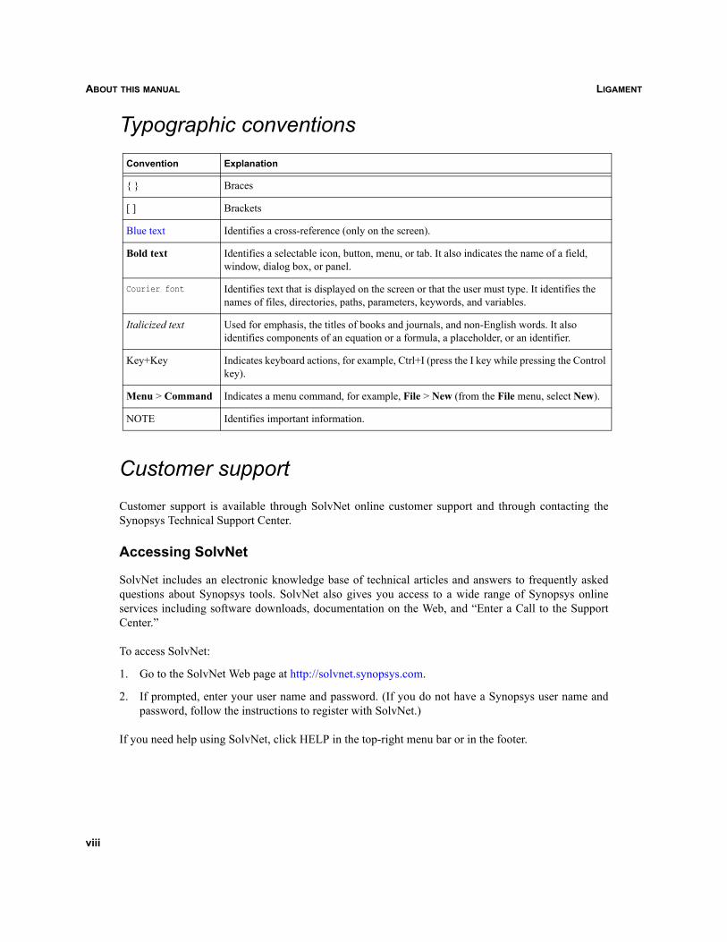
Typographic conventions
Customer supportCustomer support is available through SolvNet online customer support and through contacting theSynopsys Technical Support Center.
Accessing SolvNet
SolvNet includes an electronic knowledge base of technical articles and answers to frequently askedquestions about Synopsys tools. SolvNet also gives you access to a wide range of Synopsys onlineservices including software downloads, documentation on the Web, and “Enter a Call to the SupportCenter.”
To access SolvNet:
1. Go to the SolvNet Web page at http://solvnet.synopsys.com.
2. If prompted, enter your user name and password. (If you do not have a Synopsys user name andpassword, follow the instructions to register with SolvNet.)
If you need help using SolvNet, click HELP in the top-right menu bar or in the footer.
Convention Explanation
{ } Braces
[ ] Brackets
Blue text Identifies a cross-reference (only on the screen).
Bold text Identifies a selectable icon, button, menu, or tab. It also indicates the name of a field, window, dialog box, or panel.
Courier font Identifies text that is displayed on the screen or that the user must type. It identifies the names of files, directories, paths, parameters, keywords, and variables.
Italicized text Used for emphasis, the titles of books and journals, and non-English words. It also identifies components of an equation or a formula, a placeholder, or an identifier.
Key+Key Indicates keyboard actions, for example, Ctrl+I (press the I key while pressing the Control key).
Menu > Command Indicates a menu command, for example, File > New (from the File menu, select New).
NOTE Identifies important information.
viii
LIGAMENT ABOUT THIS MANUAL
Contacting the Synopsys Technical Support Center
If you have problems, questions, or suggestions, you can contact the Synopsys Technical Support Centerin the following ways:
Open a call to your local support center from the Web by going to http://solvnet.synopsys.com(Synopsys user name and password required), then clicking “Enter a Call to the Support Center.”
Send an e-mail message to your local support center:
• E-mail [email protected] from within North America.
• Find other local support center e-mail addresses at http://www.synopsys.com/support/support_ctr.
Telephone your local support center:
• Call (800) 245-8005 from within the continental United States.
• Call (650) 584-4200 from Canada.
• Find other local support center telephone numbers at http://www.synopsys.com/support/support_ctr.
Contacting your local TCAD Support Team directly
Send an e-mail message to:
[email protected] from within North America and South America.
[email protected] from within Europe.
[email protected] from within Asia Pacific (China, Taiwan, Singapore, Malaysia,India, Australia).
[email protected] from Korea.
[email protected] from Japan.
ix

LIGAMENTABOUT THIS MANUAL
x
LIGAMENT CHAPTER 1 USING LIGAMENT
Ligament
CHAPTER 1 Using Ligament
This chapter describes the components and program modules of Ligament.
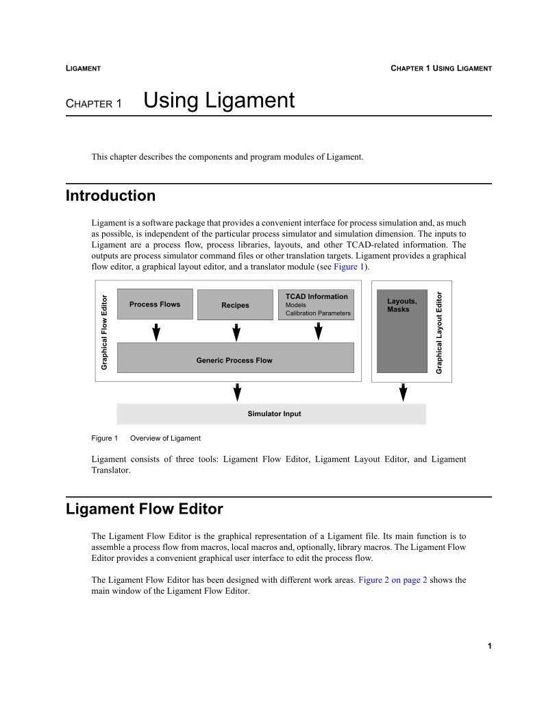
IntroductionLigament is a software package that provides a convenient interface for process simulation and, as muchas possible, is independent of the particular process simulator and simulation dimension. The inputs toLigament are a process flow, process libraries, layouts, and other TCAD-related information. Theoutputs are process simulator command files or other translation targets. Ligament provides a graphicalflow editor, a graphical layout editor, and a translator module (see Figure 1).
Figure 1 Overview of Ligament
Ligament consists of three tools: Ligament Flow Editor, Ligament Layout Editor, and LigamentTranslator.
Ligament Flow EditorThe Ligament Flow Editor is the graphical representation of a Ligament file. Its main function is toassemble a process flow from macros, local macros and, optionally, library macros. The Ligament FlowEditor provides a convenient graphical user interface to edit the process flow.
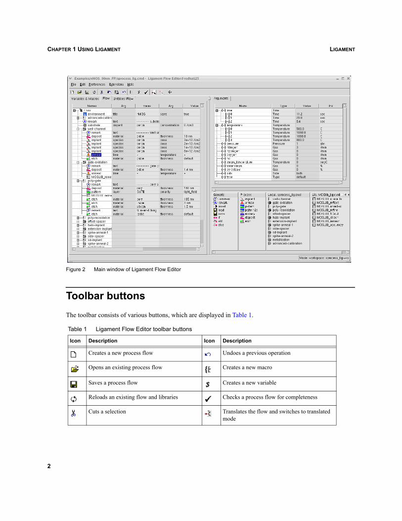
The Ligament Flow Editor has been designed with different work areas. Figure 2 on page 2 shows themain window of the Ligament Flow Editor.
Gra
phic
al F
low
Edi
tor
Generic Process Flow
Gra
phic
al L
ayou
t Edi
tor
Process Flows RecipesTCAD InformationModelsCalibration Parameters
Simulator Input
Layouts,Masks
1
LIGAMENTCHAPTER 1 USING LIGAMENT
Figure 2 Main window of Ligament Flow Editor
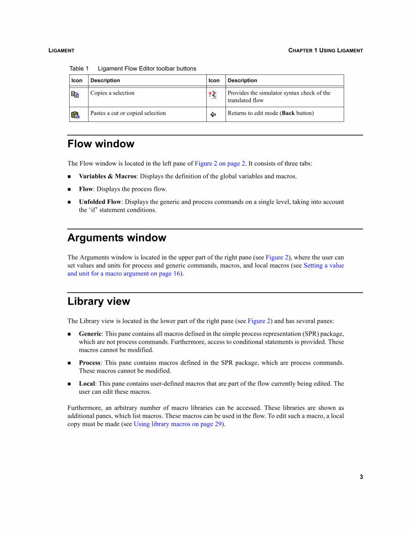
Toolbar buttonsThe toolbar consists of various buttons, which are displayed in Table 1.
Table 1 Ligament Flow Editor toolbar buttons
Icon Description Icon Description
Creates a new process flow Undoes a previous operation
Opens an existing process flow Creates a new macro
Saves a process flow Creates a new variable
Reloads an existing flow and libraries Checks a process flow for completeness
Cuts a selection Translates the flow and switches to translated mode
2
LIGAMENT CHAPTER 1 USING LIGAMENT
Flow windowThe Flow window is located in the left pane of Figure 2 on page 2. It consists of three tabs:
Variables & Macros: Displays the definition of the global variables and macros.
Flow: Displays the process flow.
Unfolded Flow: Displays the generic and process commands on a single level, taking into accountthe ‘if’ statement conditions.
Arguments windowThe Arguments window is located in the upper part of the right pane (see Figure 2), where the user canset values and units for process and generic commands, macros, and local macros (see Setting a valueand unit for a macro argument on page 16).
Library viewThe Library view is located in the lower part of the right pane (see Figure 2) and has several panes:
Generic: This pane contains all macros defined in the simple process representation (SPR) package,which are not process commands. Furthermore, access to conditional statements is provided. Thesemacros cannot be modified.
Process: This pane contains macros defined in the SPR package, which are process commands.These macros cannot be modified.
Local: This pane contains user-defined macros that are part of the flow currently being edited. Theuser can edit these macros.
Furthermore, an arbitrary number of macro libraries can be accessed. These libraries are shown asadditional panes, which list macros. These macros can be used in the flow. To edit such a macro, a localcopy must be made (see Using library macros on page 29).
Copies a selection Provides the simulator syntax check of the translated flow
Pastes a cut or copied selection Returns to edit mode (Back button)
Table 1 Ligament Flow Editor toolbar buttons
Icon Description Icon Description
3
LIGAMENTCHAPTER 1 USING LIGAMENT
Translated Flow windowThe Translated Flow window is only visible when the flow has been translated into the simulatorlanguage (see Translating a process flow on page 25 and Figure 11 on page 26).
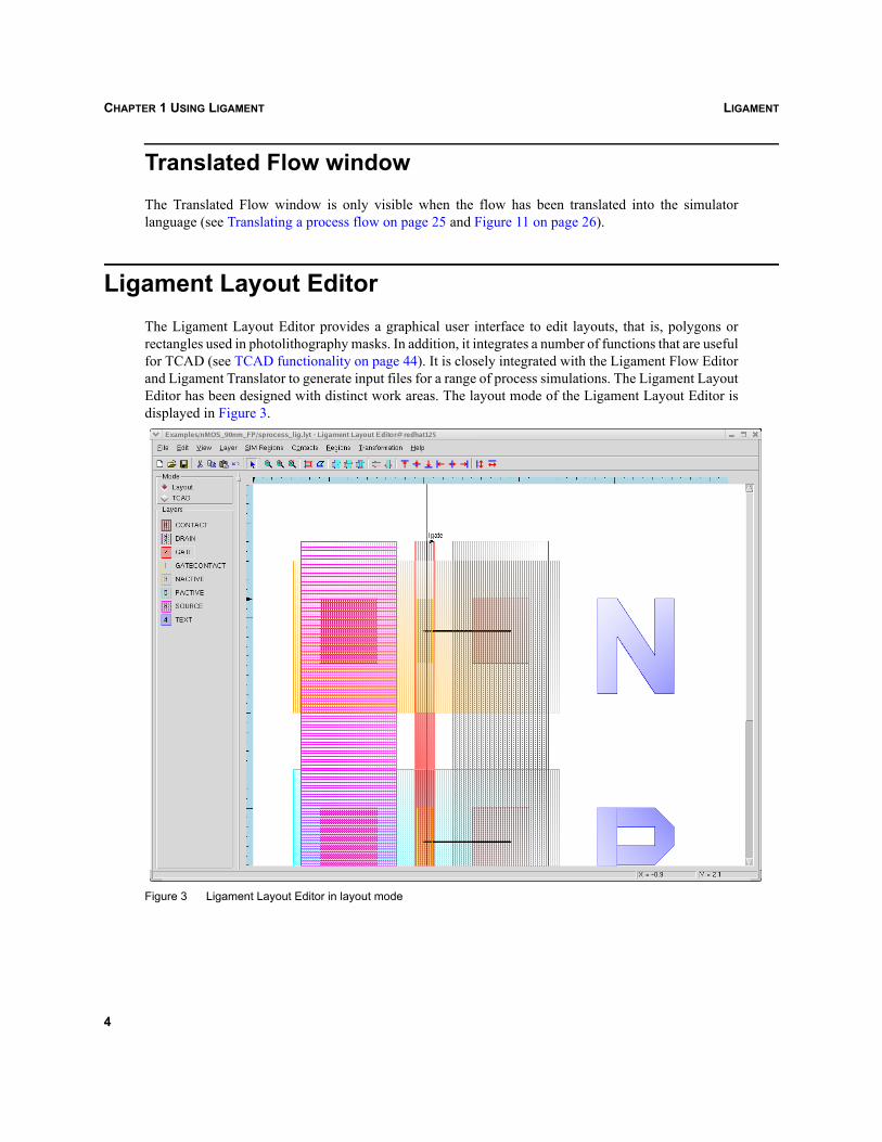
Ligament Layout EditorThe Ligament Layout Editor provides a graphical user interface to edit layouts, that is, polygons orrectangles used in photolithography masks. In addition, it integrates a number of functions that are usefulfor TCAD (see TCAD functionality on page 44). It is closely integrated with the Ligament Flow Editorand Ligament Translator to generate input files for a range of process simulations. The Ligament LayoutEditor has been designed with distinct work areas. The layout mode of the Ligament Layout Editor isdisplayed in Figure 3.
Figure 3 Ligament Layout Editor in layout mode
4
LIGAMENT CHAPTER 1 USING LIGAMENT
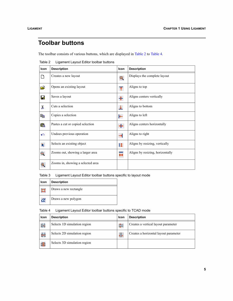
Toolbar buttonsThe toolbar consists of various buttons, which are displayed in Table 2 to Table 4.
Table 2 Ligament Layout Editor toolbar buttons
Icon Description Icon Description
Creates a new layout Displays the complete layout
Opens an existing layout Aligns to top
Saves a layout Aligns centers vertically
Cuts a selection Aligns to bottom
Copies a selection Aligns to left
Pastes a cut or copied selection Aligns centers horizontally
Undoes previous operation Aligns to right
Selects an existing object Aligns by resizing, vertically
Zooms out, showing a larger area Aligns by resizing, horizontally
Zooms in, showing a selected area
Table 3 Ligament Layout Editor toolbar buttons specific to layout mode
Icon Description
Draws a new rectangle
Draws a new polygon
Table 4 Ligament Layout Editor toolbar buttons specific to TCAD mode
Icon Description Icon Description
Selects 1D simulation region Creates a vertical layout parameter
Selects 2D simulation region Creates a horizontal layout parameter
Selects 3D simulation region
5
LIGAMENTCHAPTER 1 USING LIGAMENT
Mode selectionThe Mode group box contains two option buttons. These allow users to select one of the two operationalmodes of the Ligament Layout Editor. The Layout button is used to gain access to typical layout editingfunctionality and the TCAD button is used to gain access to the added functionality of Synopsys TCAD.
Layers listThis displays a list of layers in the layout. It allows users to select a particular layer for editing and tochange the way in which a particular layer is represented in a layout drawing.
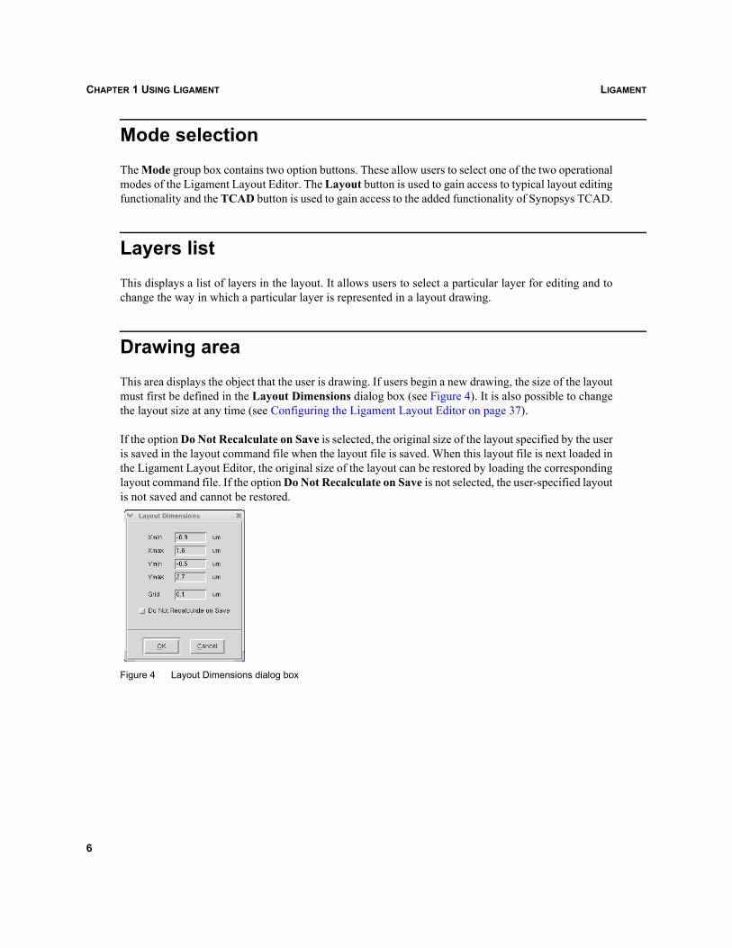
Drawing areaThis area displays the object that the user is drawing. If users begin a new drawing, the size of the layoutmust first be defined in the Layout Dimensions dialog box (see Figure 4). It is also possible to changethe layout size at any time (see Configuring the Ligament Layout Editor on page 37).
If the option Do Not Recalculate on Save is selected, the original size of the layout specified by the useris saved in the layout command file when the layout file is saved. When this layout file is next loaded inthe Ligament Layout Editor, the original size of the layout can be restored by loading the correspondinglayout command file. If the option Do Not Recalculate on Save is not selected, the user-specified layoutis not saved and cannot be restored.
Figure 4 Layout Dimensions dialog box
6
LIGAMENT CHAPTER 1 USING LIGAMENT
Ligament TranslatorLigament Translator translates the information from the Ligament language, the layout, and other datainto other formats, notably simulator-specific language. Ligament Translator supports the SynopsysTCAD simulators Dios, Sentaurus Process, Sentaurus Structure Editor, TSUPREM-4, and SentaurusTopography. The simulation language and the translator modules can be customized, and new translatormodules can be added. For more information on these possibilities, contact the Synopsys TechnicalSupport Center.
7

LIGAMENTCHAPTER 1 USING LIGAMENT
8
LIGAMENT CHAPTER 2 LIGAMENT FLOW EDITOR
Ligament
CHAPTER 2 Ligament Flow Editor
This chapter provides operational information about Ligament Flow Editor.
Starting Ligament Flow EditorTo start the Ligament Flow Editor from Sentaurus Workbench:
1. In the tool flow, double-click the icon of any process simulator that supports Ligament: SentaurusProcess, Sentaurus Structure Editor, Dios, TSUPREM-4, or Sentaurus Topography.
2. Select the Use Ligament option in the Tool Properties dialog box (Tool > Properties).
3. Tool > Edit Input > Ligament Flow.
The Ligament source flow <toolname>_lig.cmd is loaded, where <toolname> is the name of thecorresponding simulator tool.
Alternatively, the Ligament Flow Editor can be started from the command line, by typing ligedit,optionally followed by command-line options and the Ligament file, the directory containing theLigament files, or a Ligament workspace. The usage can be obtained by typing ligedit -h:
ligedit -h
Usage: ligedit [options] (FLOW | WORKSPACE)
Description: The Ligament Flow Editor is a graphical tool for editing SPR (Simple Process Representation) flows.
Options: -h[elp] : displays this help message -v[ersion] : displays the version number -verbose : prints processing info -simulator NAME : sets a target simulator for translation -default : sets default settings and preferences -lib FILE : appends flow library file to search libraries -lib REPOSITORY: appends hierarchical macro library directory to search libraries -layout FILE : adds layout file -layoutcmd FILE : layout command file -contact FILE : adds contact file -input NAME : the language of input flow, SPR by default -lws FILE : workspace file -simopt STRING : simulator-specific options -log FILE : puts the information about resolution of macro calls to the log file -mode MODE : activates the specified mode -noanneal : skips all diffusion steps of the current flow -noimplant : skips all implantation steps of the current flow-oxidationonly : leaves only oxidation annealing steps (at least one gas)
9
LIGAMENTCHAPTER 2 LIGAMENT FLOW EDITOR
"VARNAME=VALUE" : expands @VARNAME@ to VALUE
Arguments: FLOW : a process flow file, or WORKSPACE : a process workspace file
MODE: standard : the standard mode (default setting) advanced : loads all available extensions path : loads the extension specified by the path
REPOSITORY: Definition: DIRECTORY [RepositoryOptions] RepositoryOptions: -prefer {DIRECTORY .. DIRECTORY} : the list of preferable subdirectories -exclude {DIRECTORY .. DIRECTORY} : the list of prohibited subdirectories -resolvetoflow : supported by Ligament Translator only -resolvetolib FILE : supported by Ligament Translator only
For internal use: -libdir DIRECTORY : Ligament Translator library location -tpl DIRECTORY : workspace template location
Non-used options supported for compatibility: -region, -layers, -flow, -dip, -gip, -check, -print, -unfold, -spr, -autosplit, -strip, -patch, -shell, -syntcheck
Configuring the Ligament Flow EditorThe Ligament Flow Editor contains several work areas, the Flow window, Arguments window, andLibrary view. The relative size of the areas can be changed using the pane splitters. Furthermore, twoarrangements of the areas are possible.
To select a layout:
1. Preferences > Layout.
2. Select the preferred layout.
In addition, the number and type of columns of macro arguments shown in the tree can be configured.
To obtain a view with a fixed number of arguments of any type, columns alternately indicating type andvalue:
1. Preferences > Columns > Argument Mode.
2. In the Argument Mode dialog box, select the number of arguments to be shown.
For a view with specific arguments, one argument name per column, with the column headed by theargument name:
1. Preferences > Columns > Type Mode.
2. In the Tree Column Selection dialog box, select the arguments to be shown.
10
LIGAMENT CHAPTER 2 LIGAMENT FLOW EDITOR
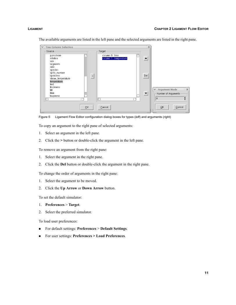
The available arguments are listed in the left pane and the selected arguments are listed in the right pane.
Figure 5 Ligament Flow Editor configuration dialog boxes for types (left) and arguments (right)
To copy an argument to the right pane of selected arguments:
1. Select an argument in the left pane.
2. Click the > button or double-click the argument in the left pane.
To remove an argument from the right pane:
1. Select the argument in the right pane.
2. Click the Del button or double-click the argument in the right pane.
To change the order of arguments in the right pane:
1. Select the argument to be moved.
2. Click the Up Arrow or Down Arrow button.
To set the default simulator:
1. Preferences > Target.
2. Select the preferred simulator.
To load user preferences:
For default settings: Preferences > Default Settings.
For user settings: Preferences > Load Preferences.
11
LIGAMENTCHAPTER 2 LIGAMENT FLOW EDITOR
NOTE The user settings are loaded automatically when Ligament is started, unless the option-default is indicated. Accordingly, the current settings are saved when the user exits theeditor.
To hide the default values of macro arguments, so that they are not visible in the columns of the Flowwindow:
1. Preferences > Default Values.
2. Select Hide or Show.
To change the order in which macro definitions are listed in the Flow window and Library view:
1. Preferences > Order Macros.
2. Select Ascend, Descend, or Definition.
To switch between different translation modes (see Translating a process flow on page 25):
1. Preferences > Translation Mode.
2. Select the preferred translation mode.
Ligament requires the functionality of the Ligament Flow Editor in order to perform various tasks withinthe work flow process.
Creating a new Ligament fileTo create a new Ligament file:
File > New, or click the corresponding toolbar icon, or Ctrl+N.
To add the initial environment and substrate command for process simulation:
Edit > Add Process Header or Ctrl+H.
Opening a Ligament command fileTo open a Ligament command file:
1. File > Open, or click the corresponding toolbar icon, or Ctrl+O.The Open dialog box is displayed.
2. Select the required Ligament file.
3. Click Open.
12
LIGAMENT CHAPTER 2 LIGAMENT FLOW EDITOR
Alternatively, a Ligament workspace comprising command file, library, and other options can be loaded(see Opening a workspace on page 62).
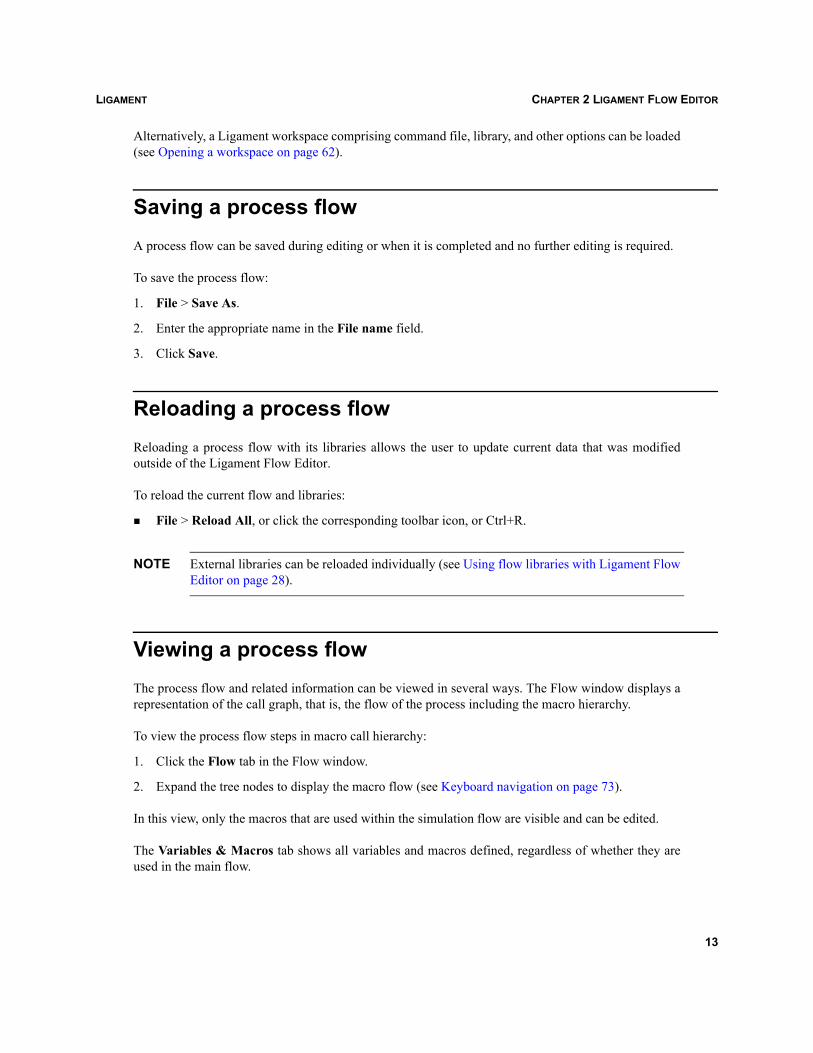
Saving a process flowA process flow can be saved during editing or when it is completed and no further editing is required.
To save the process flow:
1. File > Save As.
2. Enter the appropriate name in the File name field.
3. Click Save.
Reloading a process flowReloading a process flow with its libraries allows the user to update current data that was modifiedoutside of the Ligament Flow Editor.
To reload the current flow and libraries:
File > Reload All, or click the corresponding toolbar icon, or Ctrl+R.
NOTE External libraries can be reloaded individually (see Using flow libraries with Ligament FlowEditor on page 28).
Viewing a process flowThe process flow and related information can be viewed in several ways. The Flow window displays arepresentation of the call graph, that is, the flow of the process including the macro hierarchy.
To view the process flow steps in macro call hierarchy:
1. Click the Flow tab in the Flow window.
2. Expand the tree nodes to display the macro flow (see Keyboard navigation on page 73).
In this view, only the macros that are used within the simulation flow are visible and can be edited.
The Variables & Macros tab shows all variables and macros defined, regardless of whether they areused in the main flow.
13
LIGAMENTCHAPTER 2 LIGAMENT FLOW EDITOR
To view all user-defined variables and macros:
1. Click the Variables & Macros tab in the Flow window.
2. Expand the Macros tree node to view the list of defined macros.
3. Expand the Variables tree node to view the list of defined variables.
The Unfolded Flow tab displays the flat flow from the hierarchical view comprising predefined macros.Therefore, user-defined or library-defined macros are not visible. To unfold, all macro calls must beresolved using the libraries that are currently loaded in the editor. They may differ from the libraries usedduring the translation.
To view the unfolded flow:
1. Click the Unfolded Flow tab in the Flow window.
2. Expand the Unfolded Flow tree node.
In the Unfolded Flow tab, all possible macros are expanded and all possible arguments substituted.Macro arguments that are used in strings are also substituted. During unfolding, only basic checks onthe flow are made. For a more complete check, use the check function described in Checking a processflow for completeness on page 25.
NOTE The unfolded flow cannot be edited.
In addition, it is possible to find the location of the specific macro call in the original flow by double-clicking a macro. This highlights the corresponding call in the Variables & Macros tab.
If the flow has been unfolded, double-click a macro on the Variables & Macros tab or Flow tab toposition the selection in the corresponding location on the Unfolded Flow tab. If the macro call is in aconditional statement, it may not have an equivalent in the unfolded flow. Then, there will be an audiblewarning.
In all views, arguments of macros and values of variables can be seen in the Arguments window whena macro or variable is highlighted.
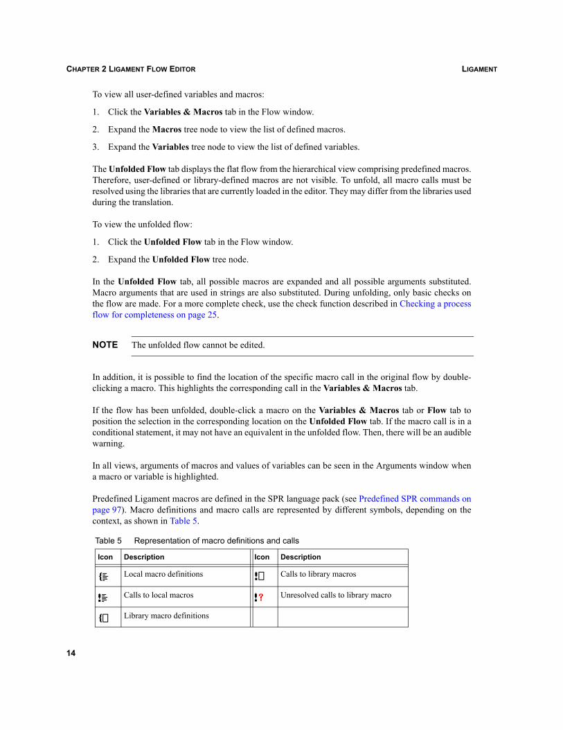
Predefined Ligament macros are defined in the SPR language pack (see Predefined SPR commands onpage 97). Macro definitions and macro calls are represented by different symbols, depending on thecontext, as shown in Table 5.
Table 5 Representation of macro definitions and calls
Icon Description Icon Description
Local macro definitions Calls to library macros
Calls to local macros Unresolved calls to library macro
Library macro definitions
14
LIGAMENT CHAPTER 2 LIGAMENT FLOW EDITOR
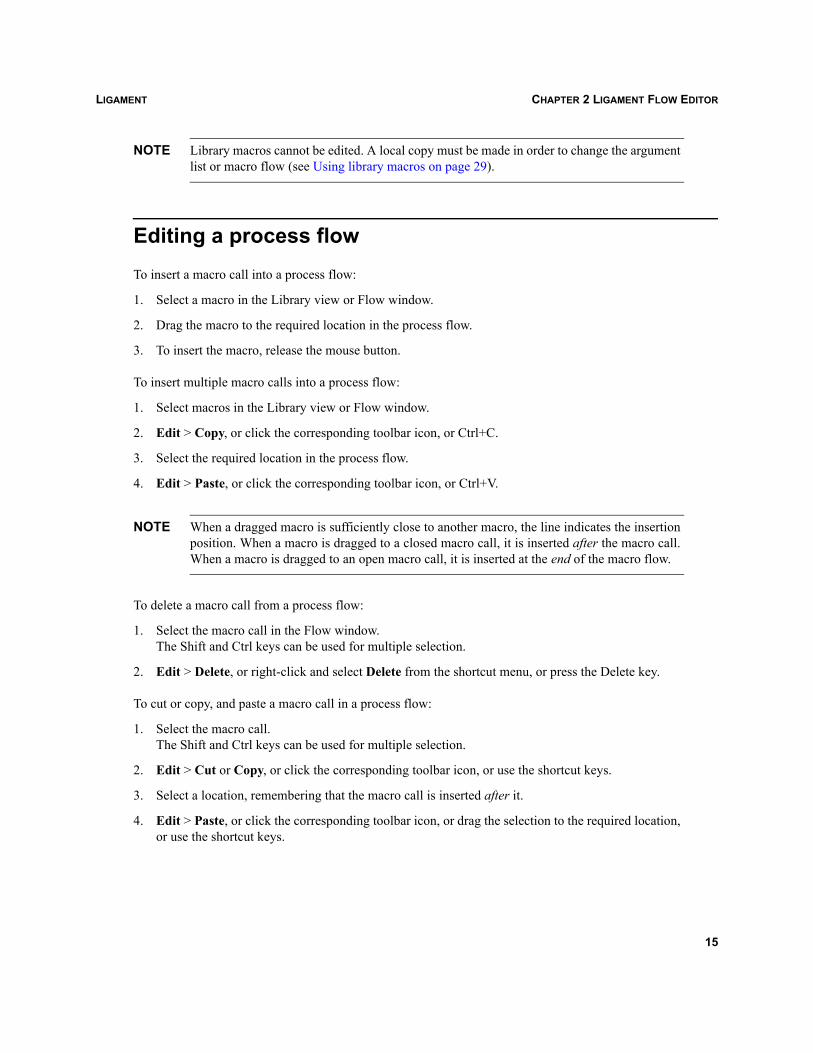
NOTE Library macros cannot be edited. A local copy must be made in order to change the argumentlist or macro flow (see Using library macros on page 29).
Editing a process flowTo insert a macro call into a process flow:
1. Select a macro in the Library view or Flow window.
2. Drag the macro to the required location in the process flow.
3. To insert the macro, release the mouse button.
To insert multiple macro calls into a process flow:
1. Select macros in the Library view or Flow window.
2. Edit > Copy, or click the corresponding toolbar icon, or Ctrl+C.
3. Select the required location in the process flow.
4. Edit > Paste, or click the corresponding toolbar icon, or Ctrl+V.
NOTE When a dragged macro is sufficiently close to another macro, the line indicates the insertionposition. When a macro is dragged to a closed macro call, it is inserted after the macro call.When a macro is dragged to an open macro call, it is inserted at the end of the macro flow.
To delete a macro call from a process flow:
1. Select the macro call in the Flow window. The Shift and Ctrl keys can be used for multiple selection.
2. Edit > Delete, or right-click and select Delete from the shortcut menu, or press the Delete key.
To cut or copy, and paste a macro call in a process flow:
1. Select the macro call.The Shift and Ctrl keys can be used for multiple selection.
2. Edit > Cut or Copy, or click the corresponding toolbar icon, or use the shortcut keys.
3. Select a location, remembering that the macro call is inserted after it.
4. Edit > Paste, or click the corresponding toolbar icon, or drag the selection to the required location,or use the shortcut keys.
15
LIGAMENTCHAPTER 2 LIGAMENT FLOW EDITOR
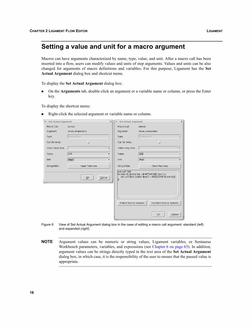
Setting a value and unit for a macro argumentMacros can have arguments characterized by name, type, value, and unit. After a macro call has beeninserted into a flow, users can modify values and units of step arguments. Values and units can be alsochanged for arguments of macro definitions and variables. For this purpose, Ligament has the SetActual Argument dialog box and shortcut menu.
To display the Set Actual Argument dialog box:
On the Arguments tab, double-click an argument or a variable name or column, or press the Enterkey.
To display the shortcut menu:
Right-click the selected argument or variable name or column.
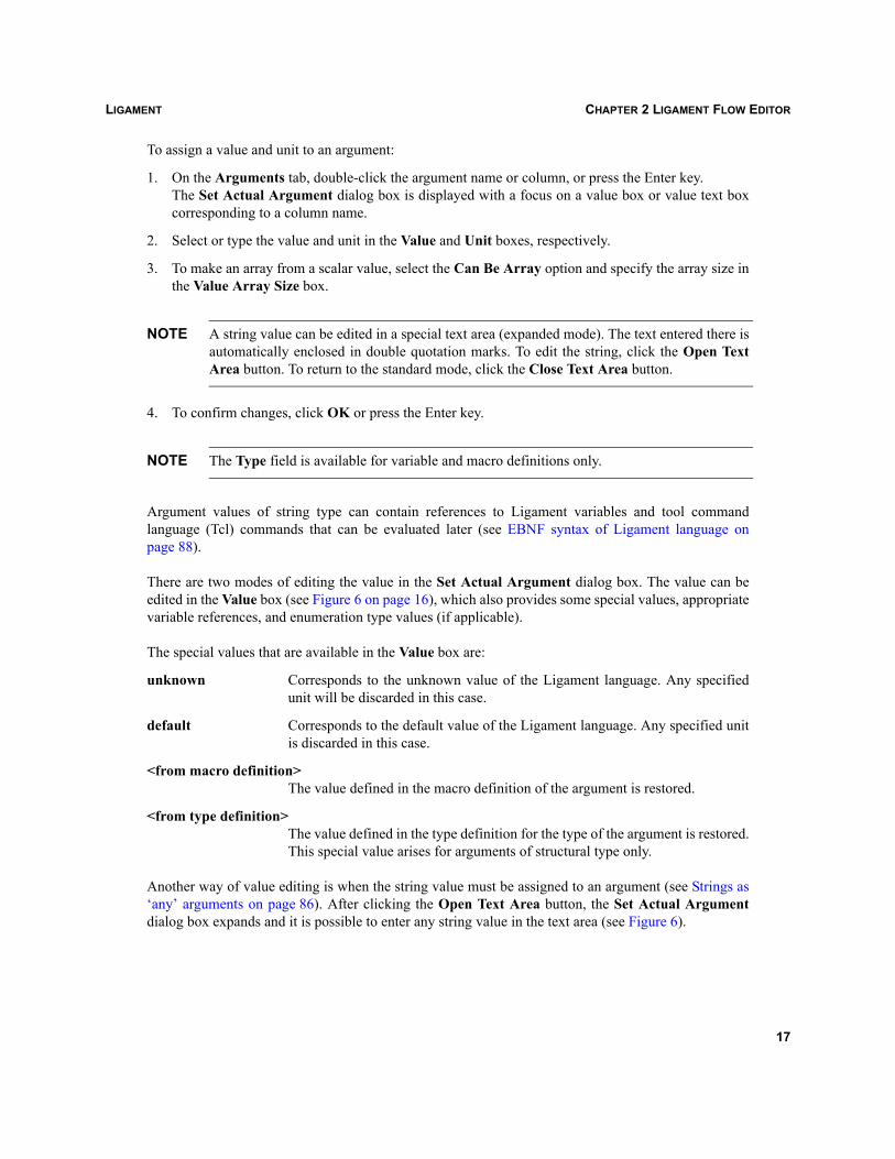
Figure 6 View of Set Actual Argument dialog box in the case of editing a macro call argument: standard (left) and expanded (right)
NOTE Argument values can be numeric or string values, Ligament variables, or SentaurusWorkbench parameters, variables, and expressions (see Chapter 6 on page 65). In addition,argument values can be strings directly typed in the text area of the Set Actual Argumentdialog box, in which case, it is the responsibility of the user to ensure that the passed value isappropriate.
16
LIGAMENT CHAPTER 2 LIGAMENT FLOW EDITOR
To assign a value and unit to an argument:
1. On the Arguments tab, double-click the argument name or column, or press the Enter key.The Set Actual Argument dialog box is displayed with a focus on a value box or value text boxcorresponding to a column name.
2. Select or type the value and unit in the Value and Unit boxes, respectively.
3. To make an array from a scalar value, select the Can Be Array option and specify the array size inthe Value Array Size box.
NOTE A string value can be edited in a special text area (expanded mode). The text entered there isautomatically enclosed in double quotation marks. To edit the string, click the Open TextArea button. To return to the standard mode, click the Close Text Area button.
4. To confirm changes, click OK or press the Enter key.
NOTE The Type field is available for variable and macro definitions only.
Argument values of string type can contain references to Ligament variables and tool commandlanguage (Tcl) commands that can be evaluated later (see EBNF syntax of Ligament language onpage 88).
There are two modes of editing the value in the Set Actual Argument dialog box. The value can beedited in the Value box (see Figure 6 on page 16), which also provides some special values, appropriatevariable references, and enumeration type values (if applicable).
The special values that are available in the Value box are:
unknown Corresponds to the unknown value of the Ligament language. Any specifiedunit will be discarded in this case.
default Corresponds to the default value of the Ligament language. Any specified unitis discarded in this case.
<from macro definition>The value defined in the macro definition of the argument is restored.
<from type definition>The value defined in the type definition for the type of the argument is restored.This special value arises for arguments of structural type only.
Another way of value editing is when the string value must be assigned to an argument (see Strings as‘any’ arguments on page 86). After clicking the Open Text Area button, the Set Actual Argumentdialog box expands and it is possible to enter any string value in the text area (see Figure 6).
17
LIGAMENTCHAPTER 2 LIGAMENT FLOW EDITOR
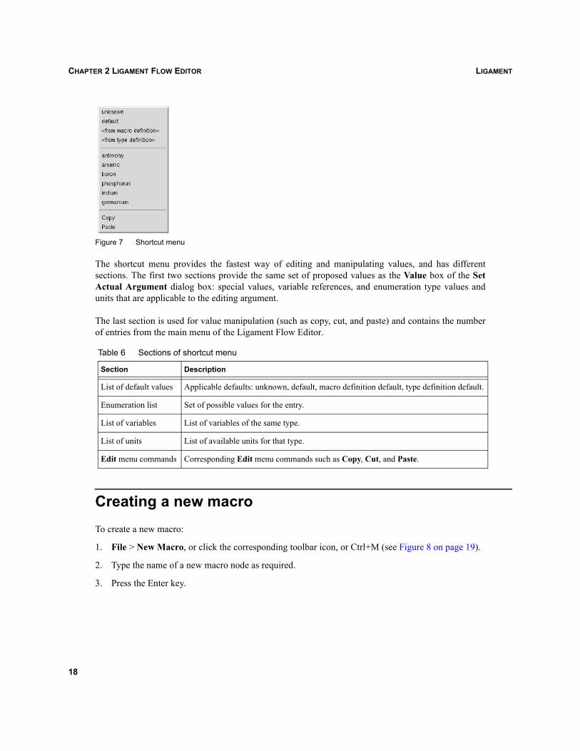
Figure 7 Shortcut menu
The shortcut menu provides the fastest way of editing and manipulating values, and has differentsections. The first two sections provide the same set of proposed values as the Value box of the SetActual Argument dialog box: special values, variable references, and enumeration type values andunits that are applicable to the editing argument.
The last section is used for value manipulation (such as copy, cut, and paste) and contains the numberof entries from the main menu of the Ligament Flow Editor.
Creating a new macroTo create a new macro:
1. File > New Macro, or click the corresponding toolbar icon, or Ctrl+M (see Figure 8 on page 19).
2. Type the name of a new macro node as required.
3. Press the Enter key.
Table 6 Sections of shortcut menu
Section Description
List of default values Applicable defaults: unknown, default, macro definition default, type definition default.
Enumeration list Set of possible values for the entry.
List of variables List of variables of the same type.
List of units List of available units for that type.
Edit menu commands Corresponding Edit menu commands such as Copy, Cut, and Paste.
18
LIGAMENT CHAPTER 2 LIGAMENT FLOW EDITOR
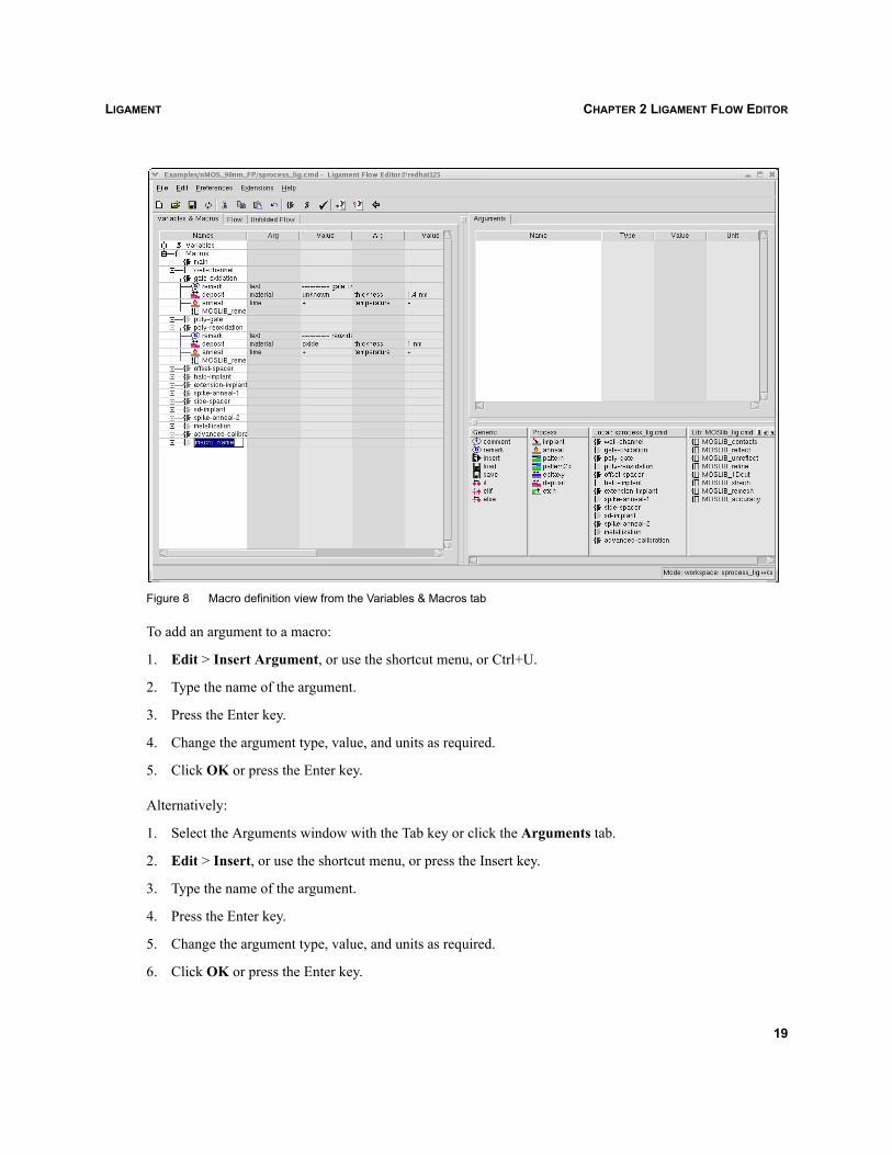
Figure 8 Macro definition view from the Variables & Macros tab
To add an argument to a macro:
1. Edit > Insert Argument, or use the shortcut menu, or Ctrl+U.
2. Type the name of the argument.
3. Press the Enter key.
4. Change the argument type, value, and units as required.
5. Click OK or press the Enter key.
Alternatively:
1. Select the Arguments window with the Tab key or click the Arguments tab.
2. Edit > Insert, or use the shortcut menu, or press the Insert key.
3. Type the name of the argument.
4. Press the Enter key.
5. Change the argument type, value, and units as required.
6. Click OK or press the Enter key.
19
LIGAMENTCHAPTER 2 LIGAMENT FLOW EDITOR
To change the order of the arguments:
1. Select an argument.
2. Edit > Move Up or Move Down, or use the shortcut menu.
To delete an argument:
1. Select an argument from the tree.
2. Edit > Delete, or use the shortcut menu, or press the Delete key.
Modifying a macro nameTo modify the name of a macro:
1. Select the required macro in the Local macros window, or under the Macros tree in the Flowwindow.
2. Edit > Rename or Ctrl+E.
3. Change the name as required.
4. Press the Enter key.A confirmation dialog box is displayed, which asks whether all corresponding macro calls are to berenamed.
5. Click Yes to rename all macro calls, click No to rename only the macro definition, or click Cancelto cancel changes.
Modifying arguments of a macro definitionTo modify an argument of a macro definition:
Select a macro in the Local library window, or under the Macros tree in the Flow window.
To rename an argument:
1. Select an argument in the Arguments window.
1. Edit > Rename, or use the shortcut menu, or Ctrl+E.
2. Type the new name.
3. Press the Enter key.
20
LIGAMENT CHAPTER 2 LIGAMENT FLOW EDITOR
To modify an argument:
1. Select an argument or an array item.
2. Press the Enter key, or double-click a node or any column.
3. Modify the argument as required in the Set Actual Argument dialog box.
4. Click OK.
NOTE To quickly change the value or unit, right-click and use the shortcut menu (see Figure 7 onpage 18).
To change the order of array items or macro arguments:
1. Select an argument or an array item.
2. Edit > Move Up or Move Down, or use the shortcut menu, or Ctrl+Up Arrow, or Ctrl+DownArrow.
Deleting a macroTo delete a macro call from the main flow:
1. Select the required macro in the main flow.
2. Edit > Delete, or use the shortcut menu, or press the Delete key.
To delete a macro definition:
1. Select a macro in the Local library window, or under the Macros tree in the Flow window.
2. Edit > Delete, or use the shortcut menu, or press the Delete key.A dialog box is displayed.
3. Click Yes to delete all macro calls in the flow, click No to delete the macro definition only, or clickCancel to cancel the deletion.
Finding a macroTo find a macro:
1. Edit > Find, or use the shortcut menu, or Ctrl+F.
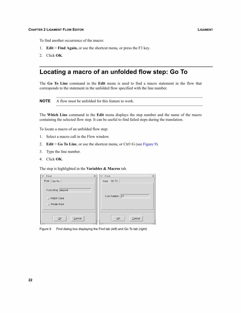
2. In the Find dialog box (see Figure 9 on page 22, left), enter the macro name in the Find What field.
3. Select the Match Case or Whole Word option as required.
4. Click OK.
21
LIGAMENTCHAPTER 2 LIGAMENT FLOW EDITOR
To find another occurrence of the macro:
1. Edit > Find Again, or use the shortcut menu, or press the F3 key.
2. Click OK.
Locating a macro of an unfolded flow step: Go ToThe Go To Line command in the Edit menu is used to find a macro statement in the flow thatcorresponds to the statement in the unfolded flow specified with the line number.
NOTE A flow must be unfolded for this feature to work.
The Which Line command in the Edit menu displays the step number and the name of the macrocontaining the selected flow step. It can be useful to find failed steps during the translation.
To locate a macro of an unfolded flow step:
1. Select a macro call in the Flow window.
2. Edit > Go To Line, or use the shortcut menu, or Ctrl+G (see Figure 9).
3. Type the line number.
4. Click OK.
The step is highlighted in the Variables & Macros tab.
Figure 9 Find dialog box displaying the Find tab (left) and Go To tab (right)
22
LIGAMENT CHAPTER 2 LIGAMENT FLOW EDITOR
Creating a new variableTo create a new variable:
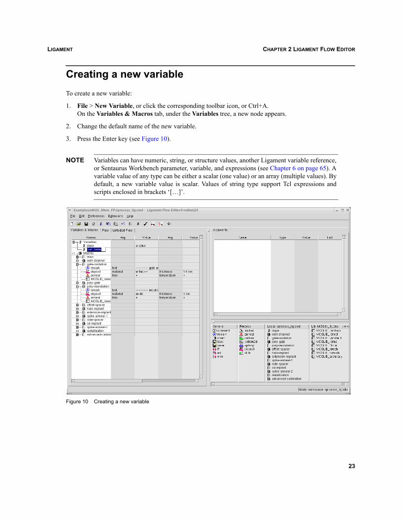
1. File > New Variable, or click the corresponding toolbar icon, or Ctrl+A.On the Variables & Macros tab, under the Variables tree, a new node appears.
2. Change the default name of the new variable.
3. Press the Enter key (see Figure 10).
NOTE Variables can have numeric, string, or structure values, another Ligament variable reference,or Sentaurus Workbench parameter, variable, and expressions (see Chapter 6 on page 65). Avariable value of any type can be either a scalar (one value) or an array (multiple values). Bydefault, a new variable value is scalar. Values of string type support Tcl expressions andscripts enclosed in brackets ‘[…]’.
Figure 10 Creating a new variable
23
LIGAMENTCHAPTER 2 LIGAMENT FLOW EDITOR
Using variablesVariables can be used in all arguments with the $variable name notation and within all string arguments.The edited process must be self-consistent in order to start a process simulation. This means that allLigament variables are replaced, so the resulting unfolded flow does not contain variables.
When used within string arguments, variables can be substituted within a string in several ways:
$variable is replaced by the variable value, followed, if there is a unit, by a space and the unit.
${variable} is replaced by the variable value.
${variable,new_unit} is replaced by the variable value converted to the new unit. The new unit mustbe compatible with the unit of the variable.
The substituted variable values can be seen in the unfolded flow.
NOTE If the variable is a structure, an array, or an array of structures, it is possible to use substitutionfor part of the variable (array item, structure field).Reference notation $variable(identifier,...,identifier) should be used (see Referencingarrays and structures on page 83). This type of substitution is also supported within strings.
Modifying a variableTo modify a variable:
1. Select a variable in the Local library window or under the Variables tree in the Flow window.
2. Double-click the Value column corresponding to variable node in the Flow window, or double-clickthe value node or any column on the Arguments tab.
3. Modify the variable as required (see Figure 6 on page 16).
4. Click OK or press the Enter key.
To rename a variable:
1. Select a variable in the Local Library window or Flow window.
2. Edit > Rename, or use the shortcut menu, or Ctrl+E.
3. Change the name as required.
4. Press the Enter key.
24
LIGAMENT CHAPTER 2 LIGAMENT FLOW EDITOR
Checking a process flow for completenessA process flow can be checked for completeness of entries. This ensures that the Ligament translationphase works when the editing is finished. The process flow can be checked by two methods:
File > Check or click the corresponding toolbar icon.
Open an unfolded flow node in the Unfolded Flow tab.
The Ligament Flow Editor checks the flow for:
Completeness of macros.
Correctness of macros used in the flow and other macros.
Type and correctness of arguments, and occurrence of unknown argument values.
Recursive macro calls.
Correctness of variable definitions used in the flow.
This check option can help to locate unknown entries before unfolding.
Translating a process flowWhen the flow is completed and all references are resolved, it can be translated into the simulator targettext:
File > Translate Flow or click the corresponding toolbar icon.
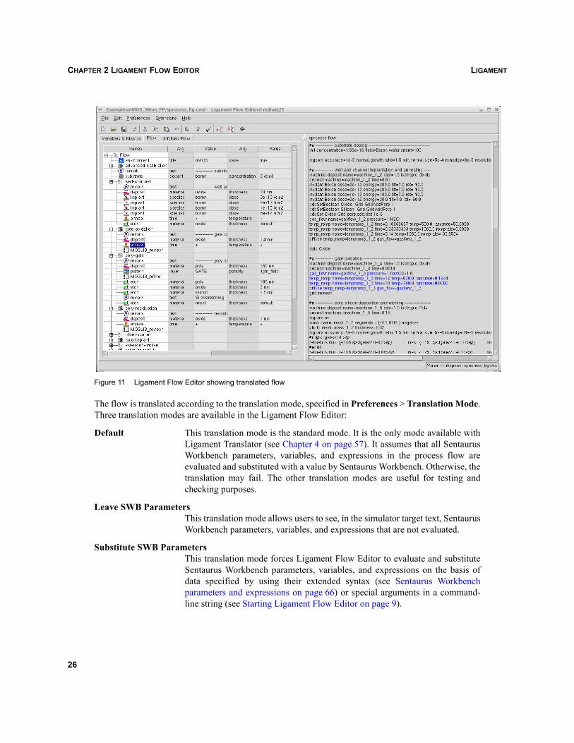
The Ligament Flow Editor switches to non-editable mode with two distinct areas. The flow is in the leftpane and the simulator target text is in the right pane (see Figure 11 on page 26).
Clicking a macro definition or a macro call node of the flow tree highlights the corresponding lines oftext in the simulator target text.
Neither the flow nor the simulator target text can be modified in this mode. To return to editable mode,click the Back button on the toolbar or change the layout (Preferences > Layout).
To save the translator target text:
1. File > Save Translated Flow As.
2. Enter the appropriate name in the File Name dialog box.
3. Click Save.
25
LIGAMENTCHAPTER 2 LIGAMENT FLOW EDITOR
Figure 11 Ligament Flow Editor showing translated flow
The flow is translated according to the translation mode, specified in Preferences > Translation Mode.Three translation modes are available in the Ligament Flow Editor:
Default This translation mode is the standard mode. It is the only mode available withLigament Translator (see Chapter 4 on page 57). It assumes that all SentaurusWorkbench parameters, variables, and expressions in the process flow areevaluated and substituted with a value by Sentaurus Workbench. Otherwise, thetranslation may fail. The other translation modes are useful for testing andchecking purposes.
Leave SWB ParametersThis translation mode allows users to see, in the simulator target text, SentaurusWorkbench parameters, variables, and expressions that are not evaluated.
Substitute SWB ParametersThis translation mode forces Ligament Flow Editor to evaluate and substituteSentaurus Workbench parameters, variables, and expressions on the basis ofdata specified by using their extended syntax (see Sentaurus Workbenchparameters and expressions on page 66) or special arguments in a command-line string (see Starting Ligament Flow Editor on page 9).
26
LIGAMENT CHAPTER 2 LIGAMENT FLOW EDITOR
Unless otherwise specified, Ligament Flow Editor will use the Default translation mode to translate theflow.
NOTE The Leave SWB Parameters translation mode should be used with caution, since it does notprovide a translation of the same quality as the other two translation modes. To provide themost accurate translation, the Ligament Flow Editor needs all Sentaurus Workbenchparameters, variables, and expressions to be evaluated and substituted with values before atranslation. To keep the Sentaurus Workbench structures that are not substituted in a simulatortarget text, some assumptions and simplifications must be made during a translation.
Checking simulator syntaxWhen the flow has been successfully translated, Ligament Flow Editor can check the syntax correctnessof the translated flow.
To check the syntax:
File > Check Translated Flow or click the corresponding toolbar icon.
The Ligament Flow Editor runs the corresponding simulator in a special syntax-checking mode. Theuser will be notified of the result of the syntax check in a standard information dialog box. If there aresyntax problems, the error and the problematic line of the translated file is printed.
Checking the syntax of a translated flow is available only in the translation mode, after the successfultranslation of the Ligament source flow. Syntax checking is also available in the command-line modewhen running the Ligament Translator: The command-line option -syntcheck must be used.
Syntax checking can save time and can prevent the user from running an incorrect simulation.
NOTE The following simulators support the syntax-checking mode: Sentaurus Process, Dios, andTSUPREM-4. All necessary settings for the syntax-checking feature are simulator specificand are stored in the Sentaurus Workbench tool database.
27
LIGAMENTCHAPTER 2 LIGAMENT FLOW EDITOR
Using flow libraries with Ligament Flow Editor
Flow library files and repositoriesLigament flow libraries are a convenient way to gain access to frequently used macros and variables,such as macros for process flow parts and process recipes, macros for useful simulator operations, andvariables that contain calibration information. The macros and variables can be referenced but notmodified. The macros and variables are resolved at translation time.
Flow libraries can have two formats: flow library files and repositories.
A flow library file is a single file that contains a collection of macros. In addition, other Ligamentcommand files can be used as libraries; the main flow of the library is completely ignored.
A repository is a directory in a file system, with an arbitrary hierarchical structure. The parent directoryof a repository can contain a number of macro library files and a number of subdirectories, which canalso contain macro library files. Each macro library file can contain only one macro. The name of themacro must match the name of the macro library file. Macro library files must have the extension .spr.
A repository is defined by its parent directory and a set of options, which affect the way a macro isresolved. Repository options specify:
The list of preferable subdirectories.
The list of excluded subdirectories.
The source of repository resolution (source flow file or flow library file).
Using flow librariesA library can be loaded in three ways:
A library file or repository can be opened from the Ligament Flow Editor:
• File > Open Library File or Ctrl+L.
• File > Open Repository or Ctrl+P.
Libraries can be indicated in a Ligament workspace (see Chapter 5 on page 61).
Libraries can be specified on the command line with the -lib option, for example:
-lib <library_file>
-lib "repository_parent_directory [<OPTIONS>]"
Several libraries can be open at the same time, but the same library cannot be opened twice.
28
LIGAMENT CHAPTER 2 LIGAMENT FLOW EDITOR
Using library macrosTo use a library macro in a simulation flow, drag the macro from the Library view to the simulation flow,or use the Copy and Paste menus, or shortcut keys.
This creates a macro call in the simulation flow. The macro definition remains in the library; however,changes in the library may affect the unfolded flow.
To make a local copy of a macro, drag the macro from the Library view to the Local macros window.Alternatively, use the Copy and Paste menus, or shortcut keys, along with the keyboard navigation (seeKeyboard navigation on page 73).
A local copy of the macro is made, which is saved with the simulation flow. The library version appearsdimmed to emphasize that this version is no longer used. Conversely, the macro can be modified in theflow.
When a repository is opened, only macro files from the repository parent directory are shown in theLibrary view. To change the parent directory of a repository, click the Edit a library button (seeTable 7), which will display the Repository Properties dialog box.
NOTE Making local copies of macros is not possible for macros from repositories.
Using library variablesLibrary variables can be used in the same way as local variables; they appear in the shortcut menus forargument editing (see Setting a value and unit for a macro argument on page 16).
To make a local copy of a variable, drag it from the Library to the Local library window or Flow window.Alternatively, use the Copy and Paste commands, or shortcut keys, along with the keyboard navigation(see Keyboard navigation on page 73).
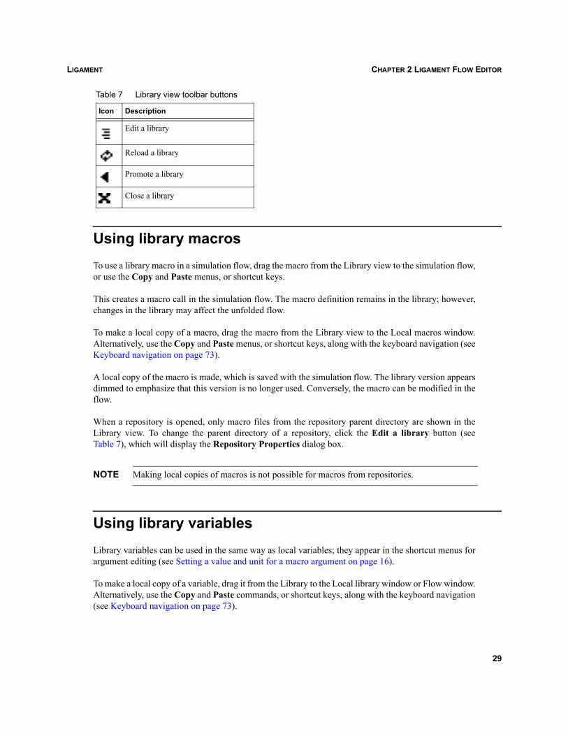
Table 7 Library view toolbar buttons
Icon Description
Edit a library
Reload a library
Promote a library
Close a library
29
LIGAMENTCHAPTER 2 LIGAMENT FLOW EDITOR
A local copy of the variable is made, which is saved with the simulation flow. The library versionappears dimmed to emphasize that this version is no longer used. Conversely, the variable can bemodified in the flow.
NOTE Only library files can contain variable definitions. Variables defined in repository macro filesare not supported.
Libraries and resolution of macros or variablesIf a macro or variable is present in several places, for example, in the currently edited flow or in one orseveral libraries, the first encountered version in the Library view (from left to right) is the relevant one.The others are ignored. The sequence of libraries can be influenced by using the Promote a librarybutton (see Table 7 on page 29). Clicking this button promotes the library, that is, it moves ahead of thelibrary to the left.
NOTE The libraries loaded in the Ligament Flow Editor are only relevant during editing, unfolding,or checking of the flow. The actual translation of the flow into simulator commands isperformed by the Ligament Translator, for which different libraries can be specified (seeUsing flow libraries with Ligament Translator on page 59).
In the case of a repository, the macro is resolved in the following way. Ligament traverses the entiredirectory hierarchy of the repository to find macro files whose names match the name of the macro. Ifthe number of matched files is more than one, the first file found will be used by Ligament to resolvemacro calls. The first file is the one found first using a breadth-first traversal algorithm, that is, the macrofiles in the top repository level take precedence over macro files in lower levels. On each individuallevel, the subdirectories are searched in alphabetic order. The search algorithm also takes into account alist of preferred subdirectories and a list of excluded subdirectories if they are specified in theRepository Properties dialog box or Ligament Flow Editor command-line string:
-prefer "<dir_name> <dir_name> ... <dir_name>"-exclude "<dir_name> <dir_name> ... <dir_name>"
If the list of preferred subdirectories is specified, these subdirectories will be searched first on each levelof the hierarchy, according to the order of the provided list. Then, the algorithm will continue thealphabetic search. Directories specified in the exclusion list will be ignored on each hierarchy level.Some examples of a Ligament Flow Editor command-line string are:
ligedit -lib /recipes/work lig.cmd
ligedit -lib "/recipes/work lig.cmd -prefer {Sim Calib}" lig.cmd
ligament -lib "/recipes/work -prefer {Sim Calib} -exclude Tool" lig.cmd
In the case of the last example, Ligament will search the macro definition on each level of the repositoryhierarchy, first in the Sim subdirectory, then in the Calib subdirectory. After that, Ligament will searchsubdirectories in alphabetic order. The Tool subdirectory will not be searched.
30
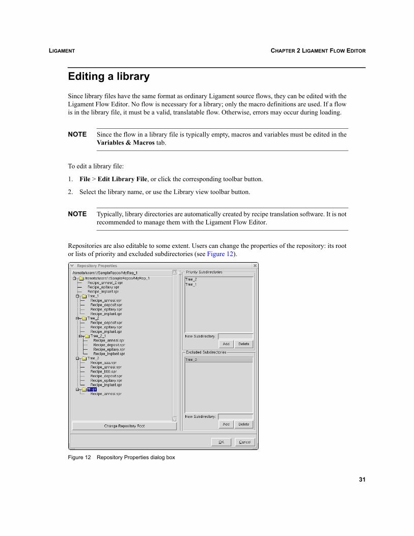
LIGAMENT CHAPTER 2 LIGAMENT FLOW EDITOR
Editing a librarySince library files have the same format as ordinary Ligament source flows, they can be edited with theLigament Flow Editor. No flow is necessary for a library; only the macro definitions are used. If a flowis in the library file, it must be a valid, translatable flow. Otherwise, errors may occur during loading.
NOTE Since the flow in a library file is typically empty, macros and variables must be edited in theVariables & Macros tab.
To edit a library file:
1. File > Edit Library File, or click the corresponding toolbar button.
2. Select the library name, or use the Library view toolbar button.
NOTE Typically, library directories are automatically created by recipe translation software. It is notrecommended to manage them with the Ligament Flow Editor.
Repositories are also editable to some extent. Users can change the properties of the repository: its rootor lists of priority and excluded subdirectories (see Figure 12).
Figure 12 Repository Properties dialog box
31
LIGAMENTCHAPTER 2 LIGAMENT FLOW EDITOR
To change properties of a repository:
1. File > Repository Properties or click the corresponding toolbar icon.
2. Select the repository name, or use the Library view toolbar button.
NOTE When loading a large repository, it takes significant time for Ligament Flow Editor to displayrecipe names in the Library view. To save time when loading, it is recommended to switch offthe display of recipe names (Preferences > Repository Content to Hide).
Reloading a libraryAfter editing a library, it is advisable to reload a library:
1. File > Reload Library or click the corresponding toolbar icon.
2. Select the library name, or use the Library view toolbar button.
NOTE The reloaded library appears at the end of the library list (the most right). It can be promotedback.
Promoting a libraryTo rearrange the libraries:
1. Select the required library.
2. Click the corresponding toolbar icon of the Local library pane.
This is useful for macros or variables that are defined in several libraries, when the order in which thelibrary is loaded determines which definition is used.
Closing a libraryTo close a library:
Click the corresponding Library view toolbar button.
32
LIGAMENT CHAPTER 2 LIGAMENT FLOW EDITOR
Converting Dios process flow to Ligament flowThe Ligament Flow Editor allows users to convert a Dios process flow to a Ligament flow. The -inputdios command-line option must be specified as follows:
ligedit -input dios dios_file
In this case, Ligament converts dios_file to the Ligament flow.
33

LIGAMENTCHAPTER 2 LIGAMENT FLOW EDITOR
34
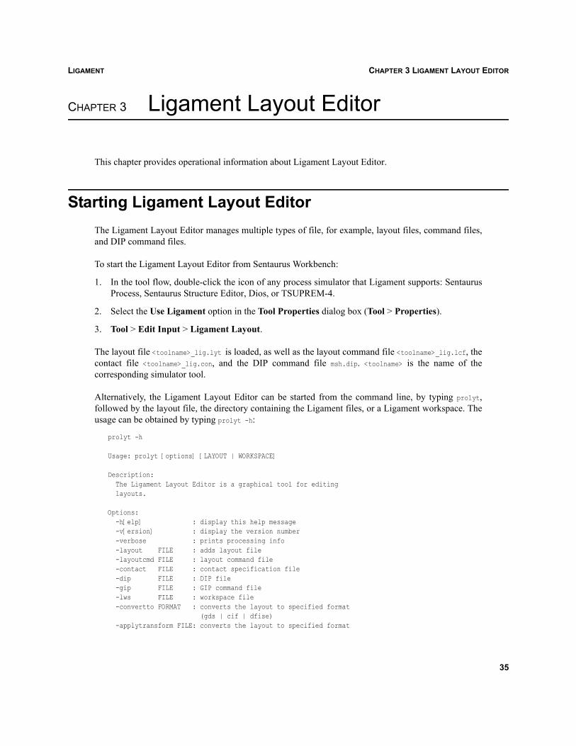
LIGAMENT CHAPTER 3 LIGAMENT LAYOUT EDITOR
Ligament
CHAPTER 3 Ligament Layout Editor
This chapter provides operational information about Ligament Layout Editor.
Starting Ligament Layout EditorThe Ligament Layout Editor manages multiple types of file, for example, layout files, command files,and DIP command files.
To start the Ligament Layout Editor from Sentaurus Workbench:
1. In the tool flow, double-click the icon of any process simulator that Ligament supports: SentaurusProcess, Sentaurus Structure Editor, Dios, or TSUPREM-4.
2. Select the Use Ligament option in the Tool Properties dialog box (Tool > Properties).
3. Tool > Edit Input > Ligament Layout.
The layout file <toolname>_lig.lyt is loaded, as well as the layout command file <toolname>_lig.lcf, thecontact file <toolname>_lig.con, and the DIP command file msh.dip. <toolname> is the name of thecorresponding simulator tool.
Alternatively, the Ligament Layout Editor can be started from the command line, by typing prolyt,followed by the layout file, the directory containing the Ligament files, or a Ligament workspace. Theusage can be obtained by typing prolyt -h:
prolyt -h
Usage: prolyt [options] [LAYOUT | WORKSPACE]
Description: The Ligament Layout Editor is a graphical tool for editing layouts.
Options: -h[elp] : display this help message -v[ersion] : display the version number -verbose : prints processing info -layout FILE : adds layout file -layoutcmd FILE : layout command file -contact FILE : contact specification file -dip FILE : DIP file -gip FILE : GIP command file -lws FILE : workspace file -convertto FORMAT : converts the layout to specified format (gds | cif | dfise) -applytransform FILE: converts the layout to specified format
35
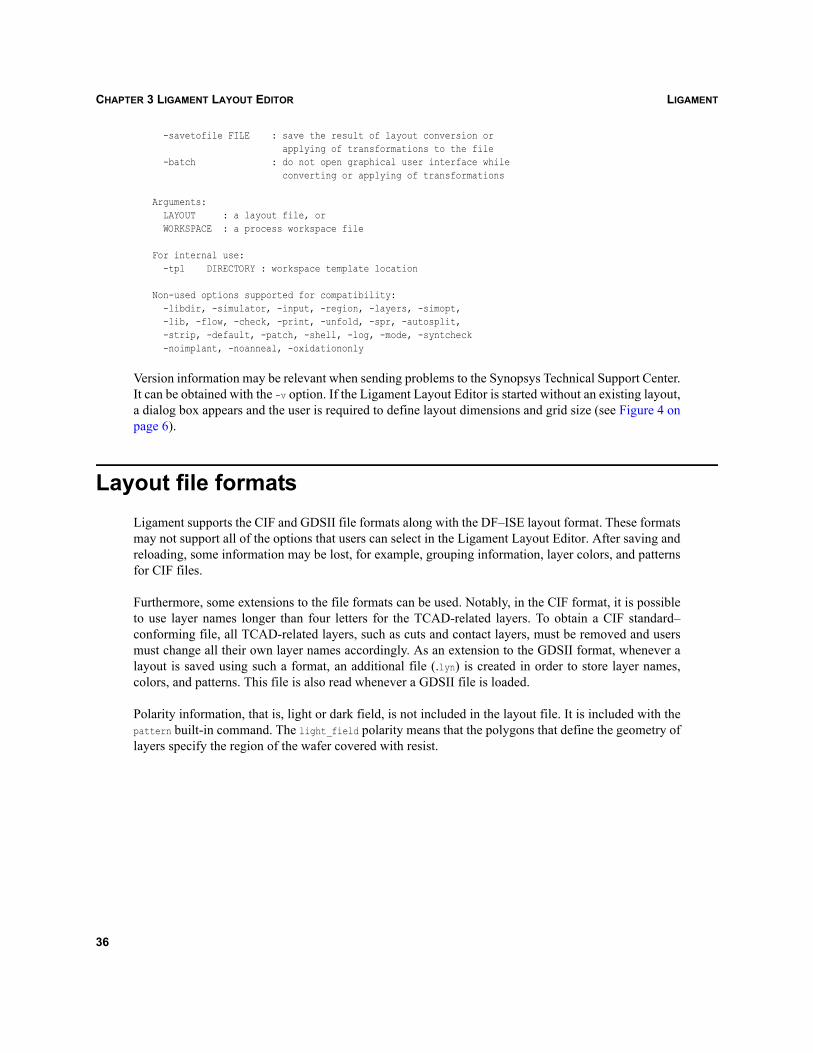
LIGAMENTCHAPTER 3 LIGAMENT LAYOUT EDITOR
-savetofile FILE : save the result of layout conversion or applying of transformations to the file -batch : do not open graphical user interface while converting or applying of transformations
Arguments: LAYOUT : a layout file, or WORKSPACE : a process workspace file
For internal use: -tpl DIRECTORY : workspace template location
Non-used options supported for compatibility: -libdir, -simulator, -input, -region, -layers, -simopt, -lib, -flow, -check, -print, -unfold, -spr, -autosplit, -strip, -default, -patch, -shell, -log, -mode, -syntcheck -noimplant, -noanneal, -oxidationonly
Version information may be relevant when sending problems to the Synopsys Technical Support Center.It can be obtained with the -v option. If the Ligament Layout Editor is started without an existing layout,a dialog box appears and the user is required to define layout dimensions and grid size (see Figure 4 onpage 6).
Layout file formatsLigament supports the CIF and GDSII file formats along with the DF–ISE layout format. These formatsmay not support all of the options that users can select in the Ligament Layout Editor. After saving andreloading, some information may be lost, for example, grouping information, layer colors, and patternsfor CIF files.
Furthermore, some extensions to the file formats can be used. Notably, in the CIF format, it is possibleto use layer names longer than four letters for the TCAD-related layers. To obtain a CIF standard–conforming file, all TCAD-related layers, such as cuts and contact layers, must be removed and usersmust change all their own layer names accordingly. As an extension to the GDSII format, whenever alayout is saved using such a format, an additional file (.lyn) is created in order to store layer names,colors, and patterns. This file is also read whenever a GDSII file is loaded.
Polarity information, that is, light or dark field, is not included in the layout file. It is included with thepattern built-in command. The light_field polarity means that the polygons that define the geometry oflayers specify the region of the wafer covered with resist.
36
LIGAMENT CHAPTER 3 LIGAMENT LAYOUT EDITOR
Configuring the Ligament Layout EditorIf starting a new layout, users must first define the layout dimensions in the Layout Dimensions dialogbox (see Figure 4 on page 6). Users can also change the layout size at any time. To change the layoutsize:
1. Select the Layout option in the Mode group box.
2. View > Layout Dimensions.
3. From the Layout Dimensions dialog box, change dimensions as required.
The user must also set the grid size when starting a new layout. This size can also be specified in theLayout Dimensions dialog box. Drawing and moving operations snap to that grid (see Drawing objectson page 38 and Positioning objects on page 39).
NOTE The minimal grid size supported by Ligament Layout Editor is 0.1 nm.
Users can also set the background color of the layout:
1. View > Background Color.
2. Select the color as required.
Navigating the Ligament Layout EditorUsers of Ligament require the functionality of the Ligament Layout Editor to perform various taskswithin the layout.
Creating a new layoutTo create a new layout:
File > New Layout, or click the corresponding toolbar icon, or Ctrl+L.
Opening a layoutTo open an existing layout:
File > Open Layout, or click the corresponding toolbar icon, or Ctrl+Y.
The file format is automatically detected.
37
LIGAMENTCHAPTER 3 LIGAMENT LAYOUT EDITOR
Importing layouts and layout librariesMultiple layouts can be imported into the current layout. The file format is automatically detected andcan vary between the files. Two options exist to import layouts depending on how the new layout isstored. In the following explanation, it is assumed that Layout A is displayed and Layout B is imported.
To import a layout:
1. File > Import Layout or Ctrl+M.
2. Select the layout file to be imported and click Open.
3. From the Import Option dialog box, click Yes to merge layouts or click No to reference layouts.
Option A: Merging layouts
Layout B merges into Layout A. When Layout A is saved, Layout B data is also saved in the Layout Afile. Layout B is not modified.
Option B: Referencing layouts or layout libraries
Layout B is not merged into Layout A. Layout libraries allow the user to keep layout-related and TCAD-related layers in separate files.
Any new drawing that is created after Layout B has been imported by reference is stored in the LayoutA file, even if it belongs to layers defined in Layout B. A layout library is loaded as a single object, thatis, single polygons within Layout B cannot be modified, edited, or removed.
Since referenced layouts are not saved in the main layout file, they have to be indicated again toLigament Translator, either through command-line options (see Starting Ligament Translator onpage 57) or workspaces (see Chapter 5 on page 61).
Drawing objectsTo draw an object in the drawing area:
1. Select the Layout option in the Mode group box.
2. Select the required layer from the Layers list.
3. Click the type of object required, rectangles or polygons, using the toolbar buttons (see Table 3 onpage 5).
38
LIGAMENT CHAPTER 3 LIGAMENT LAYOUT EDITOR
To draw a rectangle:
1. Press and hold the mouse button for a corner.
2. Drag the pointer diagonally and release the button.
To draw a polygon:
1. Press and hold the mouse button for a corner.
2. Drag the pointer for a short distance and release the button.
3. Click the mouse button once for each required corner.
4. Double-click for the final corner.
Selecting objectsTo select a single object:
1. Select the required layer from the Layers list.
2. Click in the toolbar.
3. Click an object.
To select a group of objects:
1. Click in the toolbar.
2. Drag the mouse to draw a selection frame around the objects to be grouped.
To deselect an object:
Click outside of the object selection.
Positioning objectsThe positioning operations apply to both the layout mode and TCAD mode.
To alter the position of a single object:
1. Select the object (see Selecting objects on page 39).
2. Drag the object to the required location or use the arrow keys.
To alter the position of a group of objects:
1. Select the objects (see Selecting objects on page 39).
2. Drag the objects to the required location or use the arrow keys.
39
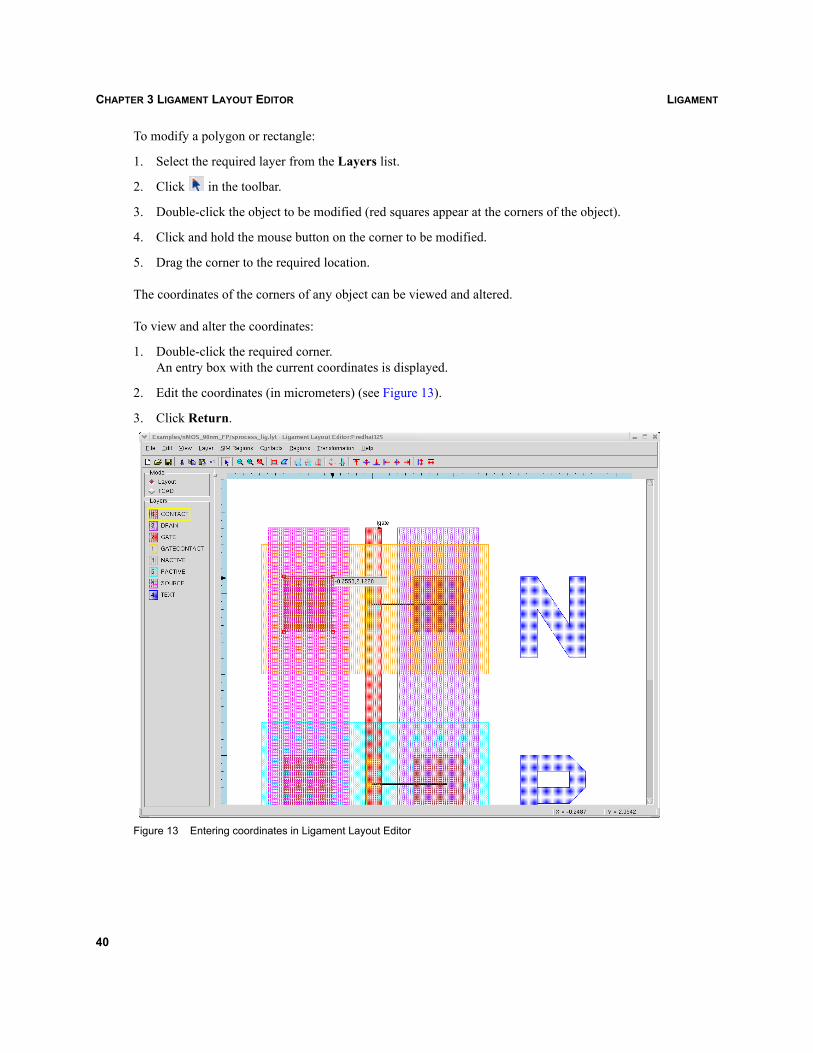
LIGAMENTCHAPTER 3 LIGAMENT LAYOUT EDITOR
To modify a polygon or rectangle:
1. Select the required layer from the Layers list.
2. Click in the toolbar.
3. Double-click the object to be modified (red squares appear at the corners of the object).
4. Click and hold the mouse button on the corner to be modified.
5. Drag the corner to the required location.
The coordinates of the corners of any object can be viewed and altered.
To view and alter the coordinates:
1. Double-click the required corner.An entry box with the current coordinates is displayed.
2. Edit the coordinates (in micrometers) (see Figure 13).
3. Click Return.
Figure 13 Entering coordinates in Ligament Layout Editor
40
LIGAMENT CHAPTER 3 LIGAMENT LAYOUT EDITOR
To remove polygon corners:
Hold the Ctrl key and click the corner to be removed.
To add polygon corners:
1. Hold the Shift key and click the corner to be duplicated.
2. Holding the mouse button, release the Shift key.
3. Move the new corner to the required location.
Aligning objectsThe positioning operations apply to both the layout mode and TCAD mode. Objects can be aligned invarious ways: to their top, bottom, left or right edges, or centers. Furthermore, they can be aligned andresized.
To align objects:
1. Click the reference object to select it.
2. Hold the Shift key and click the other objects to be added to the selection.
3. Click the appropriate alignment button.
Modifying and adding layersTo modify layers of an existing drawing:
Right-click the required layer from the Layers list.
Right-clicking progressively changes the default display style from a fill pattern to a solid style to ahidden style, and back to a fill pattern. The currently active layer (with a yellow border) cannot behidden.
To add layers:
1. Double-click a layer in the Layers list.The Edit Layers dialog box is displayed (see Figure 14 on page 42).
2. Click in the Name field to display the name options.
3. Select the required name.
4. Click in the Color field to display the color options.
5. Select the required color.
6. Click in the Pattern field to display the pattern options.
41
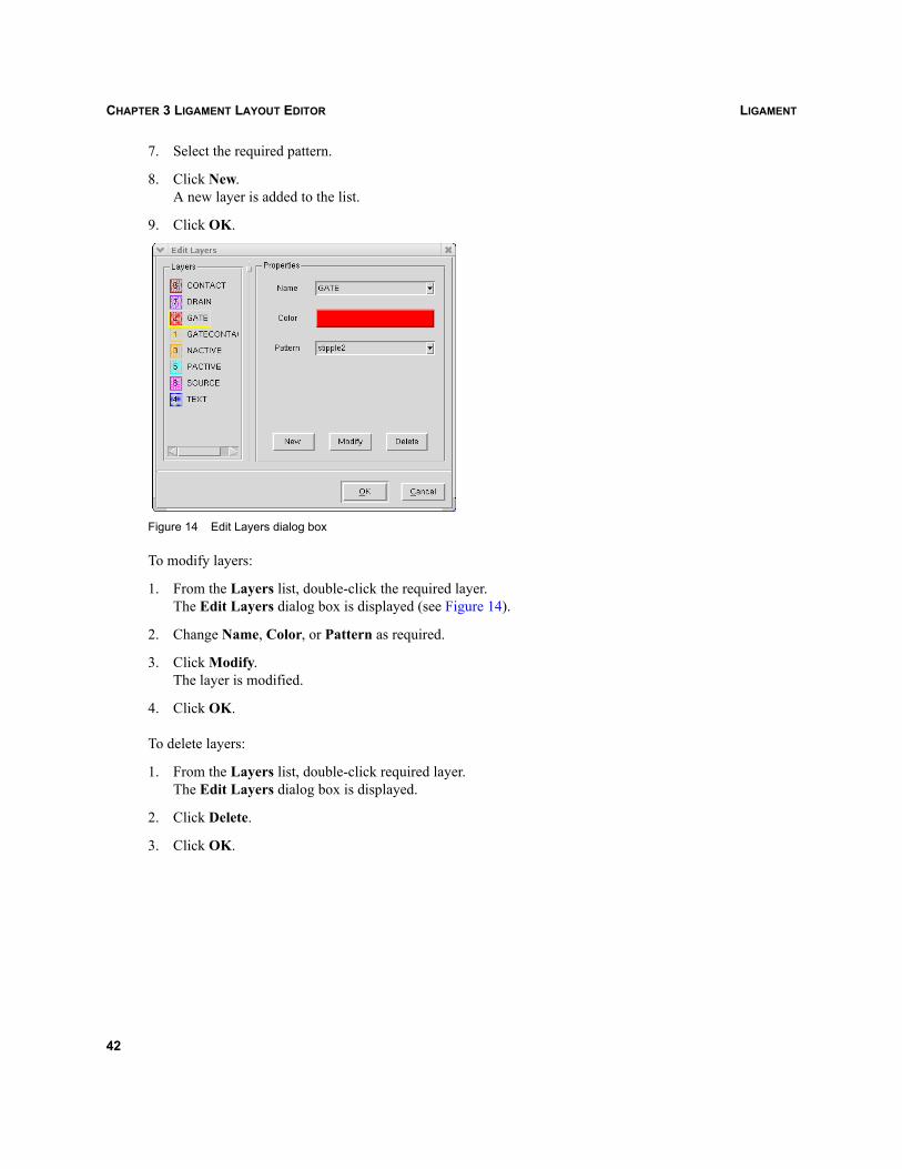
LIGAMENTCHAPTER 3 LIGAMENT LAYOUT EDITOR
7. Select the required pattern.
8. Click New.A new layer is added to the list.
9. Click OK.
Figure 14 Edit Layers dialog box
To modify layers:
1. From the Layers list, double-click the required layer.The Edit Layers dialog box is displayed (see Figure 14).
2. Change Name, Color, or Pattern as required.
3. Click Modify.The layer is modified.
4. Click OK.
To delete layers:
1. From the Layers list, double-click required layer.The Edit Layers dialog box is displayed.
2. Click Delete.
3. Click OK.
42
LIGAMENT CHAPTER 3 LIGAMENT LAYOUT EDITOR
Layer operationsLigament Layout Editor allows users to perform a number of operations on an entire layer of the layout,such as resizing the objects of a layer, rounding a layer, as well as Boolean operations. Immediatetransformations can be specified in the Immediate Transformation dialog box (see Figure 15 onpage 44). Ligament Layout Editor has its own language for describing these operations (see Layeroperations language on page 91). A help text with a short description of the language can be viewed fromthe Immediate Transformation dialog box.
To display the Immediate Transformation dialog box:
1. Select the Layout option in the Mode group box.
2. Transformation > Immediate.
Example 1
To create a new layer called NACTIVE1 from the layer NACTIVE, which is resized by 0.2 μm:
1. Enter the command NACTIVE1=resize(NACTIVE,0.2) in the Immediate Transformation dialog box.
2. Click Apply or Apply/Dismiss.
Example 2
To create a new layer called NACTIVE2 from the layer NACTIVE, which is shifted by 0.1 μm in the horizontaldirection and 0.2 μm in the vertical direction:
1. Enter the command NACTIVE2=shift(NACTIVE,0.1,0.2) in the Immediate Transformation dialog box.
2. Click Apply or Apply/Dismiss.
43
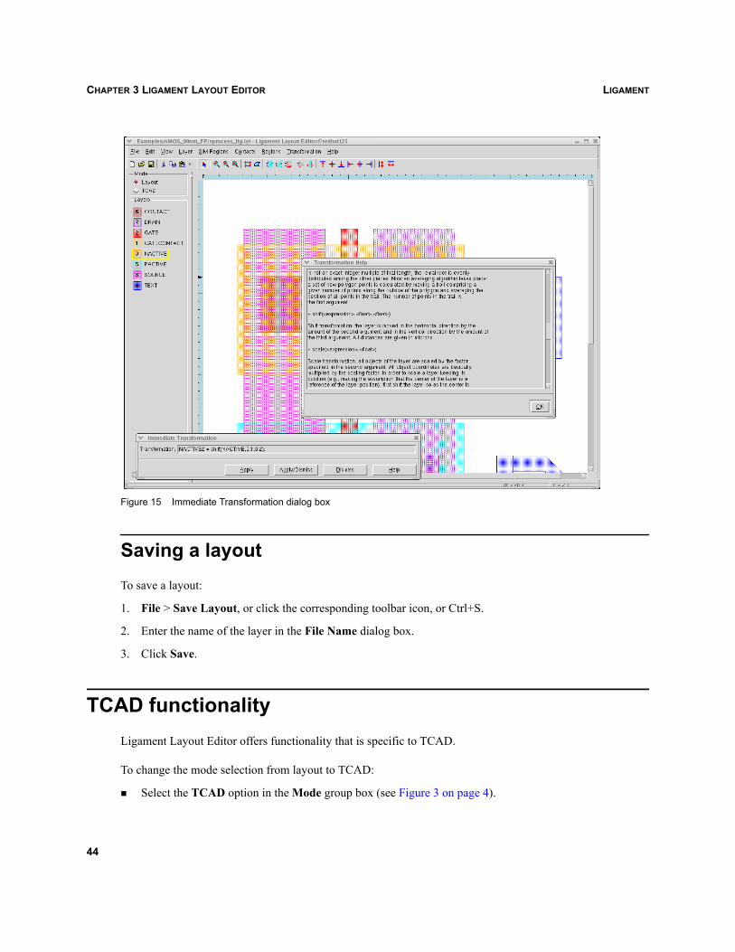
LIGAMENTCHAPTER 3 LIGAMENT LAYOUT EDITOR
Figure 15 Immediate Transformation dialog box
Saving a layoutTo save a layout:
1. File > Save Layout, or click the corresponding toolbar icon, or Ctrl+S.
2. Enter the name of the layer in the File Name dialog box.
3. Click Save.
TCAD functionalityLigament Layout Editor offers functionality that is specific to TCAD.
To change the mode selection from layout to TCAD:
Select the TCAD option in the Mode group box (see Figure 3 on page 4).
44
LIGAMENT CHAPTER 3 LIGAMENT LAYOUT EDITOR
The TCAD mode allows access to the TCAD-specific functionality of Ligament Layout Editor.Additional information that is needed is saved either in the layout file (such as for cuts and contactspecifications) or in separate files (such as for retained operations, 3D simulation–specific information,and contact information).
Some TCAD-specific information in the layout files require an extension of the limited layout fileformats. These augmented files cannot, under all circumstances, be imported back into other standard-conforming layout editors.
NOTE Ligament allows for and uses CIF files with layer names that are longer than the fourcharacters specified in the CIF standard.
The main differences between the layout and TCAD modes are:
The Layers list is replaced by the SIM Regions list.
Extra features are added to the toolbar (see Table 4 on page 5).
NOTE For TCAD operations, the user must ensure that the TCAD mode is selected.
Simulation regionsSimulation regions, or cuts, are single objects in specially named layers of the layout (see Figure 16 onpage 47).
To specify simulation regions from an existing layout and process flow:
1. Select the TCAD option in the Mode group box.
2. Click the appropriate toolbar button (see Table 4).
3. Click to indicate the point for a 1D simulation region.
4. Drag a point to indicate the line for a 2D simulation region.
5. Drag a point to obtain a rectangle for a 3D simulation region.
NOTE Simulation regions can only be points, horizontal or vertical lines, or axis-aligned rectangles.
Several cuts of each type can be specified. These layers can be referenced in Sentaurus Workbench,specifically in the Ligament Flow Editor.
45
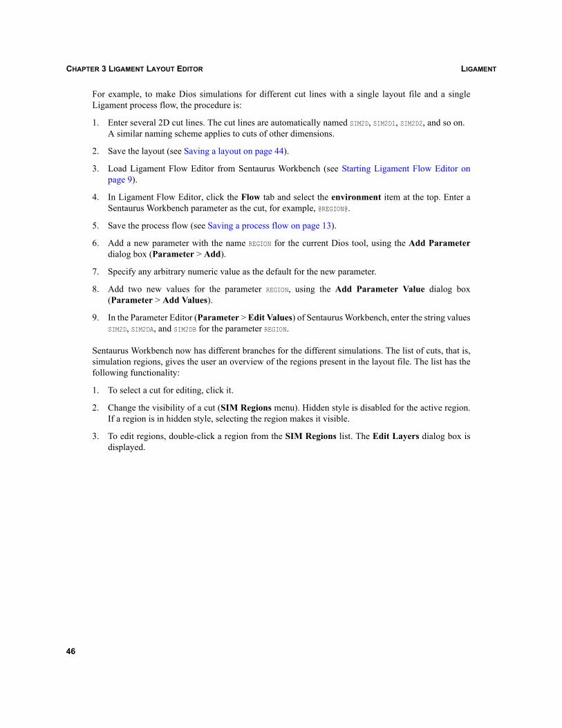
LIGAMENTCHAPTER 3 LIGAMENT LAYOUT EDITOR
For example, to make Dios simulations for different cut lines with a single layout file and a singleLigament process flow, the procedure is:
1. Enter several 2D cut lines. The cut lines are automatically named SIM2D, SIM2D1, SIM2D2, and so on. A similar naming scheme applies to cuts of other dimensions.
2. Save the layout (see Saving a layout on page 44).
3. Load Ligament Flow Editor from Sentaurus Workbench (see Starting Ligament Flow Editor onpage 9).
4. In Ligament Flow Editor, click the Flow tab and select the environment item at the top. Enter aSentaurus Workbench parameter as the cut, for example, @REGION@.
5. Save the process flow (see Saving a process flow on page 13).
6. Add a new parameter with the name REGION for the current Dios tool, using the Add Parameterdialog box (Parameter > Add).
7. Specify any arbitrary numeric value as the default for the new parameter.
8. Add two new values for the parameter REGION, using the Add Parameter Value dialog box(Parameter > Add Values).
9. In the Parameter Editor (Parameter > Edit Values) of Sentaurus Workbench, enter the string valuesSIM2D, SIM2DA, and SIM2DB for the parameter REGION.
Sentaurus Workbench now has different branches for the different simulations. The list of cuts, that is,simulation regions, gives the user an overview of the regions present in the layout file. The list has thefollowing functionality:
1. To select a cut for editing, click it.
2. Change the visibility of a cut (SIM Regions menu). Hidden style is disabled for the active region.If a region is in hidden style, selecting the region makes it visible.
3. To edit regions, double-click a region from the SIM Regions list. The Edit Layers dialog box isdisplayed.
46
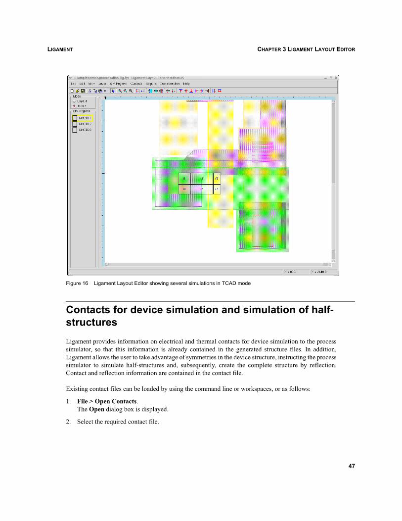
LIGAMENT CHAPTER 3 LIGAMENT LAYOUT EDITOR
Figure 16 Ligament Layout Editor showing several simulations in TCAD mode
Contacts for device simulation and simulation of half-structuresLigament provides information on electrical and thermal contacts for device simulation to the processsimulator, so that this information is already contained in the generated structure files. In addition,Ligament allows the user to take advantage of symmetries in the device structure, instructing the processsimulator to simulate half-structures and, subsequently, create the complete structure by reflection.Contact and reflection information are contained in the contact file.
Existing contact files can be loaded by using the command line or workspaces, or as follows:
1. File > Open Contacts.The Open dialog box is displayed.
2. Select the required contact file.
47

LIGAMENTCHAPTER 3 LIGAMENT LAYOUT EDITOR
To save contact and reflection information:
1. File > Save Contacts As.
2. Enter the appropriate name in the File Name dialog box.
3. Click Save.
If a contact file has been loaded, the Save Contacts and Save All commands of the File menu also savethe information. The two types of contact definition are global and local.
Global contacts
Global contacts are contacts that are automatically matched to the processed structure by the processsimulator. The user is not required to indicate the position of the contact. Possible global contacts arebulk, anode, wellleft, and wellright.
To create a global contact:
1. Contacts > Global Contacts.
2. Select the required global contact from the list.
Local contacts
Local contacts are defined in the layout as rectangles or polygons in specially named layers of the layout.When the layer is created in TCAD mode, the contact objects, rectangles, and polygons must be drawnin the layout mode.
To create a local contact:
1. Contacts > Create Contact Layer.
2. Select the required contact layer from the list.
Complete or partial simulation of the back-end part of the process must occur, and the contact materialmust be deposited on the structure to enable correct positioning of the contact from the mask.
NOTE In Ligament, users can assign multiple locations for the same contact. However, the actualaddition of the contacts to the structure is performed by the targeted process simulator, whichmay have limitations with respect to handling contacts with multiple locations.
48
LIGAMENT CHAPTER 3 LIGAMENT LAYOUT EDITOR
Reflection of half-structures
It is possible to perform the process simulation for half a structure, with a subsequent reflection todisplay the entire structure. To indicate the direction of the reflection:
1. Contacts > Reflection.
2. Select the required reflection from the list.
Information for the local contacts is created in the half-structure and, subsequently, reflected to the fullstructure. The contact layers outside the simulation region are not examined. ‘Source’ and ‘drain’contacts are handled specially during reflection: ‘source’ contacts in the original half-structure changeto ‘drain’ contacts in the reflected part, and ‘drain’ contacts change to ‘source’ contacts.
Layout parameterization and retained layer commandsInformation for layout parameterization and retained layer operations is saved in the layout commandfile. Existing layout command files can be loaded by using the command line or workspaces, or asfollows:
1. File > Open Layout Command.The Open dialog box is displayed.
2. Select the required layout command file.
To save layout parameterization:
1. File > Save Layout Command As.
2. Enter the appropriate name in the File Name dialog box.
3. Click Save.
If a layout command file has been loaded, the Save Layout Command and Save All commands of theFile menu also save the information.
According to the naming convention specified in the Sentaurus Workbench tool databases (seeSentaurus Workbench, Tool databases on page 88), the correct name for a layout command file shouldbe <toolname>_lig.lcf. If Ligament Layout Editor is run from Sentaurus Workbench and another layoutcommand file must be included in the Sentaurus Workbench project, it is necessary to open this layoutcommand file first and then save it as the <toolname>_lig.lcf file using File > Save As in Ligament.
A layout parameterization allows users to change the layout for a simulation by specifying a line throughthe layout, and stretching, shrinking, and shifting all layers across that line by the value of a givenparameter (see Figure 17 on page 50). All layers that belong to the parameterized layout change duringSentaurus Workbench preprocessing. The two types of layout parameterization are vertical andhorizontal.
49
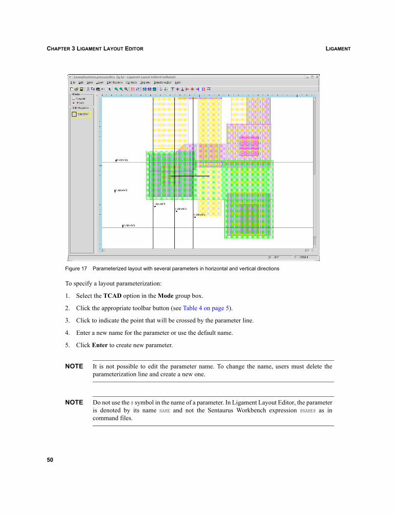
LIGAMENTCHAPTER 3 LIGAMENT LAYOUT EDITOR
Figure 17 Parameterized layout with several parameters in horizontal and vertical directions
To specify a layout parameterization:
1. Select the TCAD option in the Mode group box.
2. Click the appropriate toolbar button (see Table 4 on page 5).
3. Click to indicate the point that will be crossed by the parameter line.
4. Enter a new name for the parameter or use the default name.
5. Click Enter to create new parameter.
NOTE It is not possible to edit the parameter name. To change the name, users must delete theparameterization line and create a new one.
NOTE Do not use the @ symbol in the name of a parameter. In Ligament Layout Editor, the parameteris denoted by its name NAME and not the Sentaurus Workbench expression @NAME@ as incommand files.
50
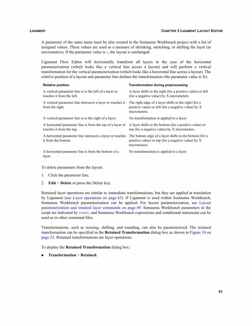
LIGAMENT CHAPTER 3 LIGAMENT LAYOUT EDITOR
A parameter of the same name must be also created in the Sentaurus Workbench project with a list ofassigned values. These values are used as a measure of shrinking, stretching, or shifting the layer (inmicrometers). If the parameter value is 0, the layout is unchanged.
Ligament Flow Editor will horizontally transform all layers in the case of the horizontalparameterization (which looks like a vertical line across a layout) and will perform a verticaltransformation for the vertical parameterization (which looks like a horizontal line across a layout). Therelative position of a layout and parameter line defines the transformation (the parameter value is X):
To delete parameters from the layout:
1. Click the parameter line.
2. Edit > Delete or press the Delete key.
Retained layer operations are similar to immediate transformations, but they are applied at translationby Ligament (see Layer operations on page 43). If Ligament is used within Sentaurus Workbench,Sentaurus Workbench parameterization can be applied. For layout parameterization, see Layoutparameterization and retained layer commands on page 49. Sentaurus Workbench parameters in thescript are indicated by @NAME@, and Sentaurus Workbench expressions and conditional statements can beused as in other command files.
Transformations, such as resizing, shifting, and rounding, can also be parameterized. The retainedtransformation can be specified in the Retained Transformation dialog box as shown in Figure 18 onpage 52. Retained transformations are layer operations.
To display the Retained Transformation dialog box:
Transformation > Retained.
Relative position Transformation during preprocessing
A vertical parameter line is to the left of a layer or touches it from the left.
A layer shifts to the right (for a positive value) or left (for a negative value) by X micrometers.
A vertical parameter line intersects a layer or touches it from the right.
The right edge of a layer shifts to the right (for a positive value) or left (for a negative value) by X micrometers.
A vertical parameter line is to the right of a layer. No transformation is applied to a layer.
A horizontal parameter line is from the top of a layer or touches it from the top.
A layer shifts to the bottom (for a positive value) or top (for a negative value) by X micrometers.
A horizontal parameter line intersects a layer or touches it from the bottom.
The bottom edge of a layer shifts to the bottom (for a positive value) or top (for a negative value) by X micrometers.
A horizontal parameter line is from the bottom of a layer.
No transformation is applied to a layer.
51
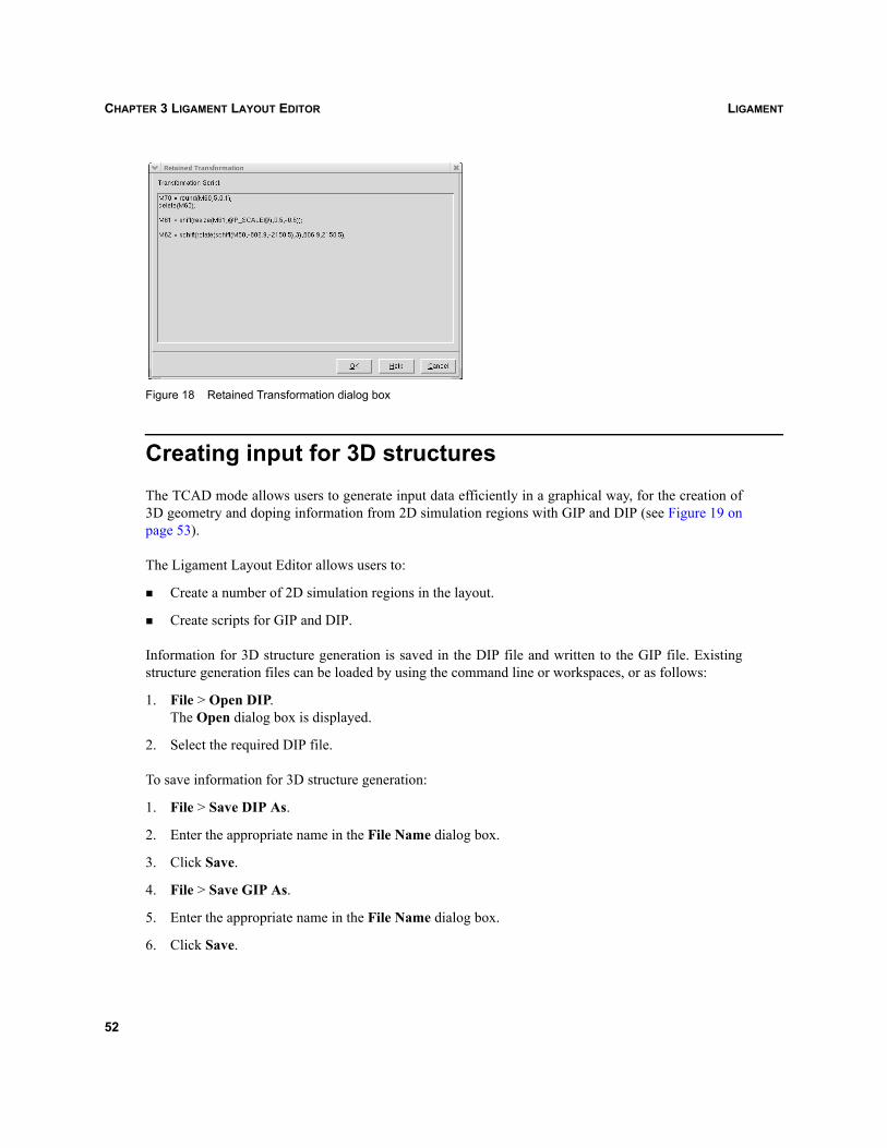
LIGAMENTCHAPTER 3 LIGAMENT LAYOUT EDITOR
Figure 18 Retained Transformation dialog box
Creating input for 3D structuresThe TCAD mode allows users to generate input data efficiently in a graphical way, for the creation of3D geometry and doping information from 2D simulation regions with GIP and DIP (see Figure 19 onpage 53).
The Ligament Layout Editor allows users to:
Create a number of 2D simulation regions in the layout.
Create scripts for GIP and DIP.
Information for 3D structure generation is saved in the DIP file and written to the GIP file. Existingstructure generation files can be loaded by using the command line or workspaces, or as follows:
1. File > Open DIP.The Open dialog box is displayed.
2. Select the required DIP file.
To save information for 3D structure generation:
1. File > Save DIP As.
2. Enter the appropriate name in the File Name dialog box.
3. Click Save.
4. File > Save GIP As.
5. Enter the appropriate name in the File Name dialog box.
6. Click Save.
52
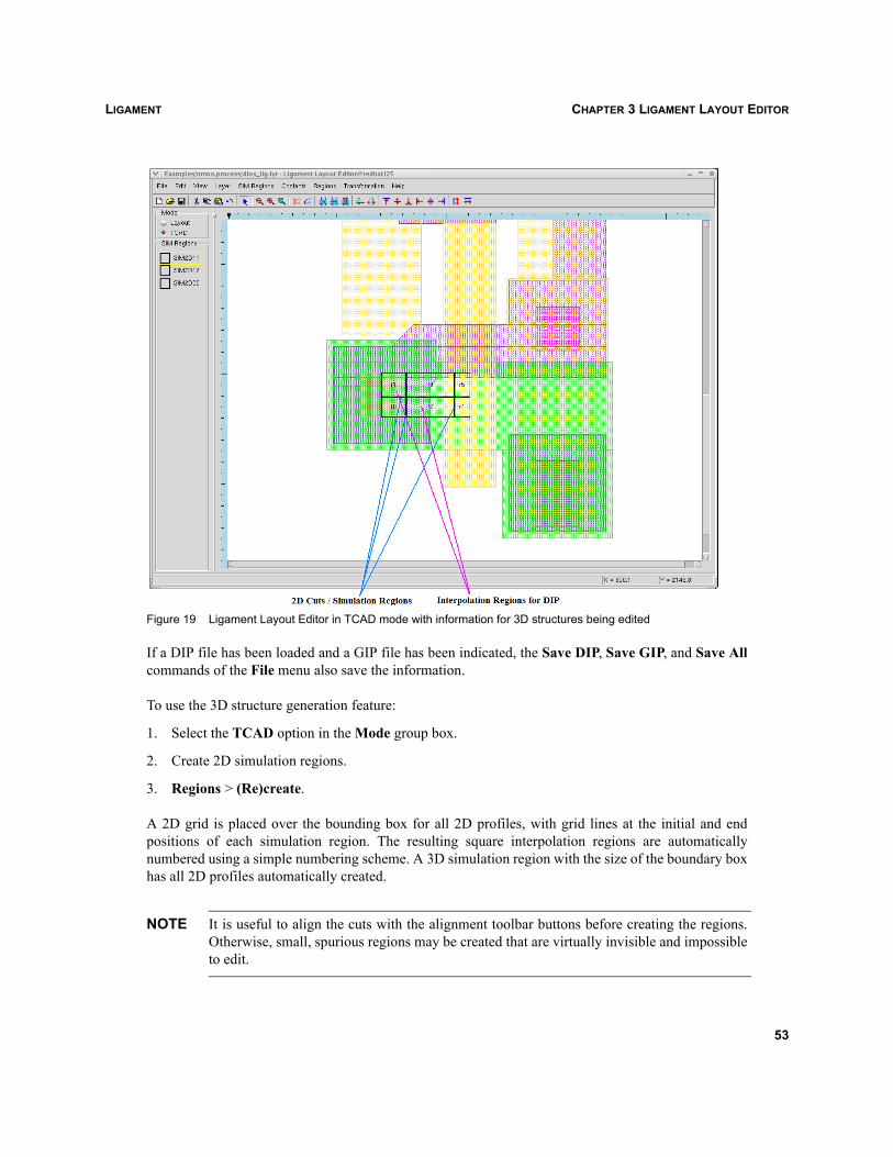
LIGAMENT CHAPTER 3 LIGAMENT LAYOUT EDITOR
Figure 19 Ligament Layout Editor in TCAD mode with information for 3D structures being edited
If a DIP file has been loaded and a GIP file has been indicated, the Save DIP, Save GIP, and Save Allcommands of the File menu also save the information.
To use the 3D structure generation feature:
1. Select the TCAD option in the Mode group box.
2. Create 2D simulation regions.
3. Regions > (Re)create.
A 2D grid is placed over the bounding box for all 2D profiles, with grid lines at the initial and endpositions of each simulation region. The resulting square interpolation regions are automaticallynumbered using a simple numbering scheme. A 3D simulation region with the size of the boundary boxhas all 2D profiles automatically created.
NOTE It is useful to align the cuts with the alignment toolbar buttons before creating the regions.Otherwise, small, spurious regions may be created that are virtually invisible and impossibleto edit.
53
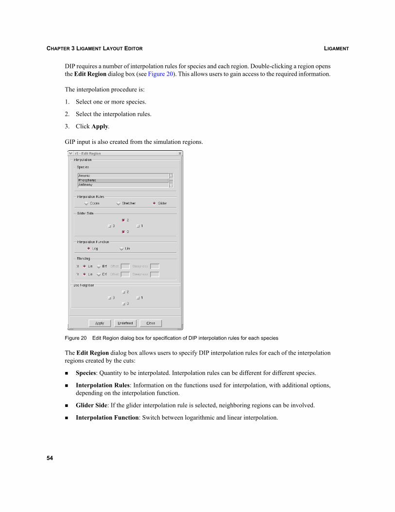
LIGAMENTCHAPTER 3 LIGAMENT LAYOUT EDITOR
DIP requires a number of interpolation rules for species and each region. Double-clicking a region opensthe Edit Region dialog box (see Figure 20). This allows users to gain access to the required information.
The interpolation procedure is:
1. Select one or more species.
2. Select the interpolation rules.
3. Click Apply.
GIP input is also created from the simulation regions.
Figure 20 Edit Region dialog box for specification of DIP interpolation rules for each species
The Edit Region dialog box allows users to specify DIP interpolation rules for each of the interpolationregions created by the cuts:
Species: Quantity to be interpolated. Interpolation rules can be different for different species.
Interpolation Rules: Information on the functions used for interpolation, with additional options,depending on the interpolation function.
Glider Side: If the glider interpolation rule is selected, neighboring regions can be involved.
Interpolation Function: Switch between logarithmic and linear interpolation.
54
LIGAMENT CHAPTER 3 LIGAMENT LAYOUT EDITOR
Blending: Another option to interpolation functions.
Use Neighbor: If a region has no simulation profile on a particular side, the values can be taken froma neighboring region.
One or more species can be selected at the same time in the Species list.
To switch on interpolation for one or more species:
1. Select the required species in the Species list.
2. Select the interpolation rules.
3. Click Apply.
To switch off interpolation for one or more species:
1. Select the required species in the Species list.
2. Click Undefined.
If more than one species is selected, a user cannot see the current individual settings. The default settingsare shown.
Ligament Layout Editor in batch modeThe Ligament Layout Editor can be started in either interactive (GUI) mode or batch mode. The batchmode is used when Ligament Layout Editor is run from the command line.
The -batch command-line option must be specified to run the Ligament Layout Editor in batch mode,which is mostly used to:
Convert the input layout file to another layout format.
Apply the layout transformations from the layout command file to the input layout file.
The conversion of layout files is provided for three supported layout formats: CIF, DF–ISE, and GDSII.For example, the following command converts the input layout file sprocess_lig.lyt to the GDSIIformat:
prolyt -batch -convertto gds sprocess_lig.lyt
Using the -savetofile command-line option, Ligament Layout Editor will save the result of theconversion to a different file called converted.gds, while the original layout file sprocess_lig.lyt isunchanged:
prolyt -batch -convertto gds -savetofile converted.gds sprocess_lig.lyt
55

LIGAMENTCHAPTER 3 LIGAMENT LAYOUT EDITOR
A layout transformation executes commands for layout transformation from the layout command file(see Layout parameterization and retained layer operations on page 58) to the input layout file. Forexample, the following command applies the transformations from the layout command filesprocess_lig.lcf to the input layout file sprocess_lig.lyt:
prolyt -batch -applytransform sprocess_lig.lcf sprocess_lig.lyt
Using the -savetofile command-line option, Ligament Layout Editor will save the resulting layout withthe applied transformations in a different file called res.lyt, while the original layout filesprocess_lig.lyt is unchanged:
prolyt -batch -applytransform sprocess_lig.lcf -savetofile res.lyt sprocess_lig.lyt
56
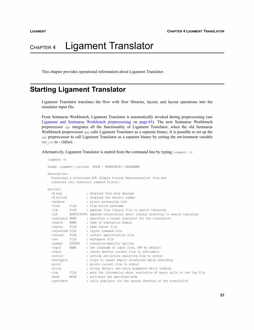
LIGAMENT CHAPTER 4 LIGAMENT TRANSLATOR
Ligament
CHAPTER 4 Ligament Translator
This chapter provides operational information about Ligament Translator.
Starting Ligament TranslatorLigament Translator translates the flow with flow libraries, layout, and layout operations into thesimulator input file.
From Sentaurus Workbench, Ligament Translator is automatically invoked during preprocessing (seeLigament and Sentaurus Workbench preprocessing on page 65). The new Sentaurus Workbenchpreprocessor spp integrates all the functionality of Ligament Translator, when the old SentaurusWorkbench preprocessor gpp calls Ligament Translator as a separate binary. It is possible to set up thespp preprocessor to call Ligament Translator as a separate binary by setting the environment variableNEW_LIG to 0 (false).
Alternatively, Ligament Translator is started from the command line by typing ligament -h.
ligament -h
Usage: ligament [options] (FLOW | WORKSPACE) [BASENAME]
Description: Translates a structured SPR (Simple Process Representation) flow and libraries into simulator command file(s).
Options: -h[elp] : displays this help message -v[ersion] : displays the version number -verbose : prints processing info -flow FILE : flow source pathname -lib FILE : appends flow library file to search libraries -lib REPOSITORY: appends hierarchical macro library directory to search libraries -simulator NAME : specifies a target simulator for the translation -region NAME : name of simulation domain -layout FILE : adds layout file -layoutcmd FILE : layout command file -contact FILE : contact specification file -lws FILE : workspace file -simopt STRING : simulator-specific options -input NAME : the language of input flow, SPR by default -check : checks whether current flow is unfoldable -unfold : unfolds and prints resulting flow to stdout -autosplit : tries to insert #split directives while unfolding -print : prints current flow to stdout -strip : strips default and extra arguments while loading -log FILE : puts the information about resolution of macro calls to the log file -mode MODE : activates the specified mode -syntcheck : calls simulator for the syntax checking of the translation
57
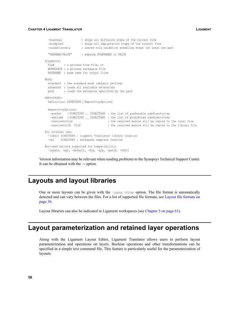
LIGAMENTCHAPTER 4 LIGAMENT TRANSLATOR
-noanneal : skips all diffusion steps of the current flow -noimplant : skips all implantation steps of the current flow -oxidationonly : leaves only oxidation annealing steps (at least one gas)
"VARNAME=VALUE" : expands @VARNAME@ to VALUE
Arguments: FLOW : a process flow file, or WORKSPACE : a process workspace file BASENAME : base name for output files
MODE: standard : the standard mode (default setting) advanced : loads all available extensions path : loads the extension specified by the path
REPOSITORY: Definition: DIRECTORY [RepositoryOptions]
RepositoryOptions:-prefer {DIRECTORY .. DIRECTORY} : the list of preferable subdirectories-exclude {DIRECTORY .. DIRECTORY} : the list of prohibited subdirectories-resolvetoflow : the resolved macros will be copied to the local flow-resolvetolib FILE : the resolved macros will be copied to the library file
For internal use: -libdir DIRECTORY : Ligament Translator library location -tpl DIRECTORY : workspace template location
Non-used options supported for compatibility: -layers, -spr, -default, -dip, -gip, -patch, -shell
Version information may be relevant when sending problems to the Synopsys Technical Support Center.It can be obtained with the –v option.
Layouts and layout librariesOne or more layouts can be given with the –layout <file> option. The file format is automaticallydetected and can vary between the files. For a list of supported file formats, see Layout file formats onpage 36.
Layout libraries can also be indicated in Ligament workspaces (see Chapter 5 on page 61).
Layout parameterization and retained layer operationsAlong with the Ligament Layout Editor, Ligament Translator allows users to perform layoutparameterization and operations on layers. Boolean operations and other transformations can bespecified in a simple text command file. This feature is particularly useful for the parameterization oflayouts.
58
LIGAMENT CHAPTER 4 LIGAMENT TRANSLATOR
In order to direct Ligament Translator to apply layer operations, the corresponding command file mustbe specified as a command-line option:
ligament -layoutcmd command_file spr_file layout_file [basename]
Ligament saves the processed commands and layout data for further reference to files<basename>_<tool_acronym>.cmd and <basename>_prl.par, respectively, where <tool_acronym> refers to thetool acronym specified in the Sentaurus Workbench tool database ("dio" for Dios, "fps" for SentaurusProcess, and so on). The file <basename>_prl.par has the same format as the original layout file. In thecase of the GDSII format, Ligament also saves a corresponding layer information file<basename>_prl.lyn.
Contacts for device simulation and simulation of half-structures
The Ligament Layout Editor supports contacts and definitions of reflection for the simulation of half-structures during layout editing (see Contacts for device simulation and simulation of half-structures onpage 47). Ligament Translator uses this information to generate input automatically for the processsimulator.
To use the contact and reflection information, which are provided by Ligament Layout Editor and storedin a separate file, the contact command-line option must be specified as follows:
ligament –contact contact_file spr_file layout_file [output]
Converting Dios process flow to Sentaurus Process process flow
Ligament Translator allows users to convert a Dios process flow to a process flow of Sentaurus Process.The -input dios command-line option must be specified as follows:
ligament -input dios -simulator sprocess dios_file
For more information, see Utilities, Chapter 6 on page 53.
Using flow libraries with Ligament TranslatorThe Ligament Translator allows for the use of libraries for variables and macros. Libraries can be in theform of library files or repositories. For a detailed description of libraries and their use in the LigamentFlow Editor, see Using flow libraries with Ligament Flow Editor on page 28.
Ligament Translator supports all the command-line options of Ligament Flow Editor. LigamentTranslator also provides additional options for repositories, which control where repository macro
59
LIGAMENTCHAPTER 4 LIGAMENT TRANSLATOR
definitions are stored after their resolution against the source flow. Resolved macro definitions can besaved in the source flow or in any specified library file.
These options are specified in the Ligament Flow Editor command-line string:
-resolvetoflow-resolvetolib <library_file>
The option -resolvetoflow specifies that resolved recipes will be copied to the local flow. The-resolvetolib option specifies that resolved recipes will be copied to the local library file library_file.With the resolve feature, users can resolve required macro definitions once and then use the local flowor the library file containing the resolved macros for subsequent use with Ligament. In this case, therepository is no longer required unless the process flow is changed. If the option -resolvetoflow or-resolvetolib is not specified, Ligament will not store the resolved macro definitions.
To obtain the resolution map, use the following Ligament command-line option:
-log <log file>
With this option, Ligament saves the information about all source flow macro calls and their resolvedmacro definitions. This option is very useful if many library files and repositories are used to resolve thesource flow.
Flow filtering capabilitiesThe Ligament Translator allows filtering of the process flow. There are three command-line options forfiltering:
-noanneal
-noimplant
-oxidationonly
The options -noanneal and -noimplant instruct the Ligament Translator to omit translation of all annealand implant statements of the source flow, respectively. The option -oxidationonly instructs the LigamentTranslator to translate only those anneal statements that correspond to an oxidation step; they have atleast one non-empty gas flow specified.
The same set of command-line options can be used when running Ligament Flow Editor.
NOTE The source flow is not changed when these command-line options are used. They influenceonly the translated flow. For each omitted step, a remark is printed in the translation flow.
60
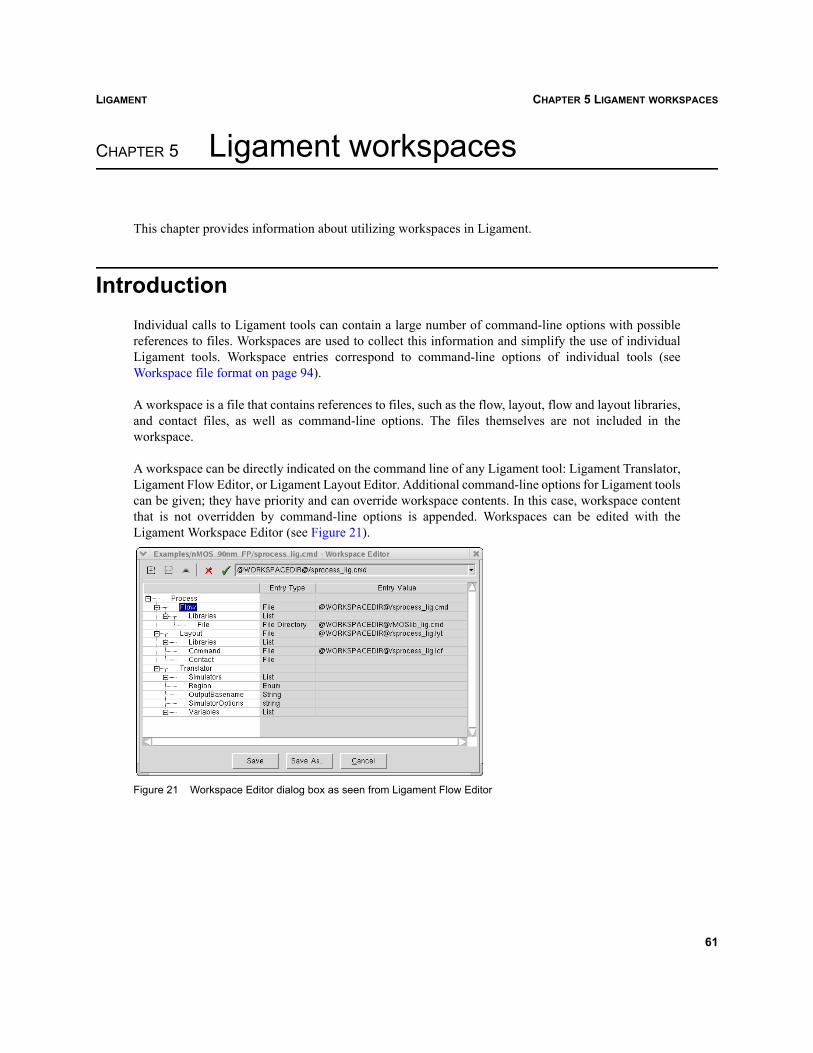
LIGAMENT CHAPTER 5 LIGAMENT WORKSPACES
Ligament
CHAPTER 5 Ligament workspaces
This chapter provides information about utilizing workspaces in Ligament.
IntroductionIndividual calls to Ligament tools can contain a large number of command-line options with possiblereferences to files. Workspaces are used to collect this information and simplify the use of individualLigament tools. Workspace entries correspond to command-line options of individual tools (seeWorkspace file format on page 94).
A workspace is a file that contains references to files, such as the flow, layout, flow and layout libraries,and contact files, as well as command-line options. The files themselves are not included in theworkspace.
A workspace can be directly indicated on the command line of any Ligament tool: Ligament Translator,Ligament Flow Editor, or Ligament Layout Editor. Additional command-line options for Ligament toolscan be given; they have priority and can override workspace contents. In this case, workspace contentthat is not overridden by command-line options is appended. Workspaces can be edited with theLigament Workspace Editor (see Figure 21).
Figure 21 Workspace Editor dialog box as seen from Ligament Flow Editor
61
LIGAMENTCHAPTER 5 LIGAMENT WORKSPACES
Creating workspacesIf no workspace file is loaded, the current state of the editor, for example, with loaded libraries andlayouts, can be written to a new workspace file as follows:
1. File > Workspace > New.The Workspace Editor is opened, with the entries initialized from the current configuration of theeditor. The workspace can now be edited (see Editing a workspace).
2. Click Save As to save the workspace file.The Save dialog box is displayed.
3. Enter the file name and location for the workspace file.
4. Click Save.
Opening a workspaceA workspace is opened either from the Ligament Flow Editor or Ligament Layout Editor by indicatingit on the command line, or as follows:
1. File > Workspace > Open.The Open dialog box is displayed.
2. Select the workspace file.
All files in the workspace that are relevant to the current editor are loaded. The workspace cansubsequently be edited.
Editing a workspaceThe Workspace Editor is opened either from the Ligament Flow Editor or Ligament Layout Editor:
File > Workspace > Edit.
Only the entries that are relevant to the respective editor are accessible. More information about whichentries are available in which tools, as well as the command-line options they refer to, can be found inWorkspace file format on page 94.
62
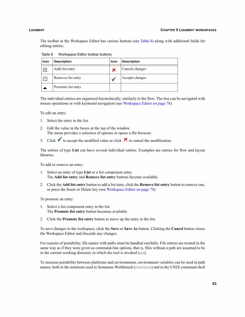
LIGAMENT CHAPTER 5 LIGAMENT WORKSPACES
The toolbar in the Workspace Editor has various buttons (see Table 8) along with additional fields forediting entries.
The individual entries are organized hierarchically, similarly to the flow. The tree can be navigated withmouse operations or with keyboard navigation (see Workspace Editor on page 78).
To edit an entry:
1. Select the entry in the list.
2. Edit the value in the boxes at the top of the window.The menu provides a selection of options or opens a file browser.
3. Click to accept the modified value or click to cancel the modification.
The entries of type List can have several individual entries. Examples are entries for flow and layoutlibraries.
To add or remove an entry:
1. Select an entry of type List or a list component entry.The Add list entry and Remove list entry buttons become available.
2. Click the Add list entry button to add a list item, click the Remove list entry button to remove one,or press the Insert or Delete key (see Workspace Editor on page 78).
To promote an entry:
1. Select a list component entry in the list.The Promote list entry button becomes available.
2. Click the Promote list entry button to move up the entry in the list.
To save changes to the workspace, click the Save or Save As button. Clicking the Cancel button closesthe Workspace Editor and discards any changes.
For reasons of portability, file names with paths must be handled carefully. File entries are treated in thesame way as if they were given as command-line options, that is, files without a path are assumed to bein the current working directory in which the tool is invoked (pwd).
To increase portability between platforms and environments, environment variables can be used in pathnames, both in the notations used in Sentaurus Workbench (@VARIABLE@) and in the UNIX command shell
Table 8 Workspace Editor toolbar buttons
Icon Description Icon Description
Adds list entry Cancels changes
Removes list entry Accepts changes
Promotes list entry
63
LIGAMENTCHAPTER 5 LIGAMENT WORKSPACES
($VARIABLE). The variable WORKSPACEDIR, which Ligament predefines, is resolved to the directory in whichthe workspace file resides.
NOTE Editing the workspace does not affect the status of the editor, that is, adding a flow or layoutlibrary to the workspace does not load the corresponding library into the editor. However, theworkspace can be reloaded.
Updating workspacesTo update a loaded workspace with the current state of the editor, for example, with loaded libraries andlayouts:
1. File > Workspace > Update.A Question dialog box is displayed.
2. Click Save to save the updated workspace or click Save As to save it under a new name.
The workspace can subsequently be edited (see Editing a workspace on page 62).
NOTE If no workspace file has been loaded, the current state of the editor, for example, with loadedlibraries and layouts, can be written to a new workspace file using the same procedure.
64
LIGAMENT CHAPTER 6 LIGAMENT AND SENTAURUS WORKBENCH
Ligament
CHAPTER 6 Ligament and Sentaurus Workbench
Sentaurus Workbench is a tool that allows users to assemble simulation flows consisting of several toolsand to parameterize the flows for design of experiments.
Ligament and Sentaurus Workbench preprocessingSentaurus Workbench provides several tool databases that encapsulate different naming conventions forSentaurus Workbench integration with other tools, including Ligament (see Sentaurus Workbench, Tooldatabases on page 88). There are three types of tool databases that can be defined on global, user, andproject levels. These databases define some values that are necessary for Ligament such as <toolname>,<tool>, and <tool_acronym>. The naming conventions described here are based on the standard SentaurusWorkbench global tool database provided with Synopsys TCAD.
Ligament Translator is used in Sentaurus Workbench preprocessing. Two stages are involved.
In the first stage, Ligament Translator is invoked to unfold the flow and potentially split the flow intoLigament input files for individual splits of the simulation, usually files pp<node>_lig.cmd. For unfolding,Ligament Translator is called as:
ligament -unfold <toolname>_lig.cmd
This call is hard-coded in Sentaurus Workbench, however, it is possible to add other options to theSentaurus Workbench preferences. For example, if the -autosplit option has been added to the commandline in the Sentaurus Workbench preferences, Ligament Translator is called as:
ligament -autosplit -unfold <toolname>_lig.cmd
If unfolding fails, the unfolded step is omitted and the input file <toolname>_lig.cmd is copied topp<node>_lig.cmd. This means that there are no true Sentaurus Workbench splits, and the simulation foreach simulation variant is a complete process simulation, that is, no common parts of the simulation areshared.
In the second stage, Ligament Translator is invoked for each of the Ligament input files for each split,that is, each pp<node>_lig.cmd, and the simulator input files n<node>_<tool_acronym>.cmd are generated. Atthis point, all Ligament libraries must be resolved.
If a layout command file is present, the resulting preprocessed layout is written to a file pp<node>_lig.lytfor visualization. These files are for reference or troubleshooting by the user only; Sentaurus Workbenchdoes not use them further. The call to Ligament Translator at the second stage is indicated in theSentaurus Workbench tool database. Additional command-line options to Ligament Translator for this
65
LIGAMENTCHAPTER 6 LIGAMENT AND SENTAURUS WORKBENCH
phase can be given on the Ligament command line, which is accessible from the Sentaurus WorkbenchTool Properties dialog box.
NOTE The abovementioned calls of Ligament Translator are implemented differently in the twoSentaurus Workbench preprocessors spp and gpp. The new preprocessor spp, introduced inVersion Y-2006.06, calls the corresponding Ligament Translator functionality internally,since Ligament Translator is integrated into spp. This is the most effective and robust solution.The alternative preprocessor gpp implements the Ligament Translator functionality by directcalls of the Ligament binary (ligament). This is much slower and less effective than the firstsolution. It is possible to use spp in gpp mode by setting the environment variable NEW_LIG to 0(false). This mode can be used for backward compatibility purposes.
Sentaurus Workbench parameters and expressionsSentaurus Workbench parameterization features are useful for creating parameterized simulationprojects or utilizing file-naming schemes that are compatible with the naming conventions of SentaurusWorkbench. For a description of the Sentaurus Workbench parameterization features, see SentaurusWorkbench, Chapter 6 on page 59.
Sentaurus Workbench parameters and variables are constants such as @parameter@. Sentaurus Workbenchexpressions are constants such as @<expression>@ or @[tcl command]@.
Sentaurus Workbench parameters are substituted with real values during preprocessing, before theLigament translation is invoked. The parameters can be used in all arguments and conditionalstatements.
In addition, all Sentaurus Workbench expressions will be evaluated and substituted with the resultingvalue, for example:
save (basename : "n@node@_pre_implant");implant (species : @SPECIES@,dose : @<4.4e+11 * FACTOR>@ /cm2,energy : @BOR_IMPL_ENRGY@ keV);if ( @<IMPL_ENERGY > 1.0>@ ) {save ();
}
In addition, Ligament provides a useful feature of the automatic creation of Sentaurus Workbenchparameters and variables in a Sentaurus Workbench project. Users can specify new SentaurusWorkbench parameters and variables only once, when a Ligament process flow is created. Each timeLigament is called for unfolding, Ligament provides Sentaurus Workbench with a full list of constantsthat are specified in the process flow with @parameter@ notation.
Then, Sentaurus Workbench automatically creates new variables and parameters in the SentaurusWorkbench project, but only for those names that still do not exist. Ligament also provides Sentaurus
66
LIGAMENT CHAPTER 6 LIGAMENT AND SENTAURUS WORKBENCH
Workbench with a list of values for each name in @parameter@ notation by introducing the extendedsyntax:
@parameter:value_1:value_2:...value_N@
With this syntax extension, users can specify a set of values to be created for the Sentaurus Workbenchparameter or variable. If no extended syntax is used, Ligament assumes that only the value of 0 is to beassigned to the parameter or variable. All new names with one value are created as Sentaurus Workbenchvariables; otherwise, as Sentaurus Workbench parameters. This extended syntax is used only byLigament. There will be no Sentaurus Workbench parameters with extended syntax in the unfolded flow;Ligament removes the colon list of values.
There is another way to specify a value for Sentaurus Workbench parameters or variables. The value canbe indicated on the Ligament Translator command line or in Ligament workspaces in the form"NAME=VALUE". Only one value can be specified for each parameter or variable. If both ways of specifyingvalues are used for the same parameter or variable (command-line argument and extended notation inthe process flow), the value from the command-line argument has priority.
When Ligament translation is invoked from Sentaurus Workbench, all Sentaurus Workbench parametersand variables are substituted with real values during preprocessing before this call. Ligament Translatorcan also be called in a stand-alone mode from the command shell. In this case, the only way to forceLigament to replace Sentaurus Workbench variables and parameters with values is by using command-line argument "NAME=VALUE".
NOTE Sentaurus Workbench parameterization is a powerful feature that should be used withcaution, since during editing, it is not possible to ensure that after preprocessing a validLigament input file is present. Errors can be difficult to detect.
Sentaurus Workbench preprocessor commandsSentaurus Workbench has several preprocessor commands, which are used during preprocessing. Theycan be divided into two groups:
Standard commands #split, #header, #endheader, #postheader, #endpostheader, #set, #define, #undef,#setdep, #remdep, #include, #includeext
Conditional commands #if, #endif, #elif, #else
For a detailed description of preprocessor commands, see Sentaurus Workbench, Preprocessor andreference syntax on page 119.
Ligament does not support direct use of Sentaurus Workbench preprocessor commands in the Ligamentsource flow file. Even if these commands appear in the Ligament source flow, Ligament will recognizethem as SPR internal comments and ignore them. To use such commands in the Ligament source flow,a special technique is required.
67
LIGAMENTCHAPTER 6 LIGAMENT AND SENTAURUS WORKBENCH
Standard preprocessor commands in LigamentThese commands can be used in Ligament by putting them in an SPR ‘comment’ statement, where #must be the first character of the comment, for example:
comment (text : "#split @BOR_IMPL_ENRGY@");
Comments containing Sentaurus Workbench preprocessor commands are analyzed by SentaurusWorkbench during the unfolding phase and are removed from the input files.
Notably, Sentaurus Workbench allows the user to ‘split’ simulations on parameter values for reasons ofsimulation efficiency. A sequential simulation, such as a process simulation, is run until the point wherea parameter is present in the input file, a simulation result is saved, and subsequent simulations withvarying parameter values can continue from this common intermediate result. This can save substantialcomputation time. A split can only be performed for the first occurrence of a parameter; later splits ofthe parameter are ignored.
It is recommended to enable splitting explicitly with the Sentaurus Workbench #split command. For useof the other preprocessor commands related to splitting, see Sentaurus Workbench, Split commands onpage 123.
An alternative is the –autosplit option of Ligament Translator, to be inserted into the SentaurusWorkbench preferences for Ligament. This provides the possibility of obtaining split points withoutexplicitly introducing #split parameters. A #split is automatically inserted in front of every parameteroccurrence during the unfolding of the flow.
NOTE Using the –autosplit option is not recommended, since this option is not robust under certaincircumstances. The feature is available for backward compatibility. Use explicit split pointsinstead.
NOTE Sentaurus Workbench parameterization is a powerful feature that should be used withcaution, since at editing time, it is not possible to ensure that after preprocessing a validLigament input file is present. Errors can be difficult to detect.
There is also the possibility to prevent a Sentaurus Workbench preprocessor command from processingduring the unfolding phase. In this case, users must protect the hash (#) symbol of the command with abackslash:
comment (text : "\#split @BOR_IMPL_ENRGY@");
The protected preprocessor command is not preprocessed during the unfolding stage and appears in theresult of the Ligament translation without a backslash, like a regular Sentaurus Workbench preprocessorcommand. Then, the Sentaurus Workbench preprocessor will process this command immediately beforestarting a simulation.
68
LIGAMENT CHAPTER 6 LIGAMENT AND SENTAURUS WORKBENCH
Conditional preprocessor commands in LigamentLigament supports its own conditional statements (see Conditional statements on page 87), which canbe used instead of Sentaurus Workbench conditional preprocessor commands in the Ligament sourceflow.
NOTE Conditional preprocessor commands can be used in Ligament in the same way as standardSentaurus Workbench preprocessor commands. However, using native Ligament conditionalstatements is more convenient, transparent, and recommended.
Using Ligament options in Sentaurus Workbench
Layout parameterizationTo use layout parameterization as defined in the Ligament Layout Editor and described in Layoutparameterization and retained layer commands on page 49, the option -layoutcmd <toolname>_lig.lcfmust be added to the command line in the Sentaurus Workbench Tool Properties dialog box.Alternatively, workspaces can be used (see Ligament workspaces on page 70).
Contact filesTo enable the use of contacts as defined in the Ligament Layout Editor along with the reflection ofsimulated 2D half-structures, as described in Contacts for device simulation and simulation of half-structures on page 47 and Contacts for device simulation and simulation of half-structures on page 59,the option -contact <toolname>_lig.con must be added to the command line in the Sentaurus WorkbenchTool Properties dialog box. Alternatively, workspaces can be used (see Ligament workspaces onpage 70).
Ligament librariesLigament allows for the use of flow libraries and layout libraries as described in Using flow librarieswith Ligament Flow Editor on page 28 and Using flow libraries with Ligament Translator on page 59.
For example, assume the use of the flow library lib3.spr, flow repository /home/user/Rep_21, and layoutlibrary c.gds. These libraries can be indicated in Sentaurus Workbench by adding them to the Ligamentcommand line in the Sentaurus Workbench Tool Properties dialog box as:
-lib lib3.spr -lib /home/user/Rep_21 -layout c.gds
69
LIGAMENTCHAPTER 6 LIGAMENT AND SENTAURUS WORKBENCH
Extended repository syntax can also be used here, but all double quotation marks and braces in therepository specification must be protected by a backslash; otherwise, the Sentaurus Workbenchpreprocessor will display an error. For example, if Ligament is to be executed with the followingrepository command-line option:
-lib "/home/user/Rep_21 -prefer {Dir_1 Dir_2 Dir_3} -exclude {BDir1 BDir2} -resolvetolib tmplib.lib"
this option should be specified using the Tool Properties dialog box (see Sentaurus Workbench,Changing tool properties on page 30) in the following way:
-lib \"/home/user/Rep_21 -prefer \{Dir_1 Dir_2 Dir_3\} -exclude \{BDir1 BDir2\} -resolvetolib tmplib.lib\"
Alternatively, workspaces can be used (see Ligament workspaces).
The following restrictions apply to libraries if they are used from Sentaurus Workbench:
Flow libraries cannot contain Sentaurus Workbench variables and splits.
Layout libraries are dynamically loaded into Ligament. Layout operations and parameterizations areperformed on the full layout.
Ligament workspacesLigament workspaces (see Chapter 5 on page 61) are a convenient means to keep collected informationtogether. For editing, the workspace mode can be used from the Sentaurus Workbench Tool Propertiesdialog box for both the Ligament Flow Editor and Ligament Layout Editor.
Ligament workspaces can be used in Sentaurus Workbench by adding the command-line option:
-lws <workspace_file>
to the command line in the Sentaurus Workbench Tool Properties dialog box. This command-lineoption applies to Ligament Flow Editor, Ligament Layout Editor, and Ligament Translator.
To work with Sentaurus Workbench and its preprocessing, some Ligament files must be named as in theSentaurus Workbench tool database even when used in workspaces.
Therefore, the following naming restrictions apply to workspaces:
The command file must be named <toolname>_lig.cmd.
The layout file must be named <toolname>_lig.lyt.
The layout command file must be named <toolname>_lig.lcf.
Furthermore, Ligament workspace files themselves are not preprocessed and neither are the filesindicated therein, with the exception of the Sentaurus Workbench files previously mentioned.
70
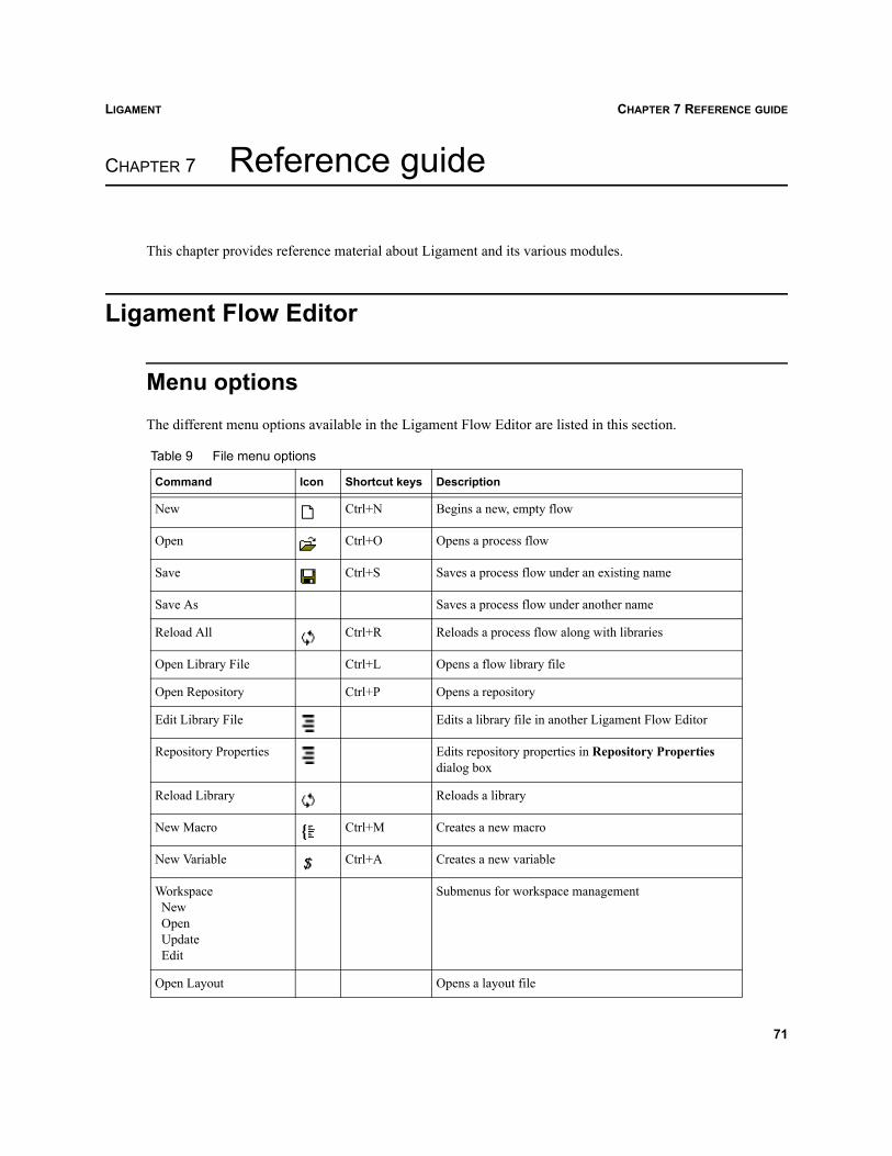
LIGAMENT CHAPTER 7 REFERENCE GUIDE
Ligament
CHAPTER 7 Reference guide
This chapter provides reference material about Ligament and its various modules.
Ligament Flow Editor
Menu optionsThe different menu options available in the Ligament Flow Editor are listed in this section.
Table 9 File menu options
Command Icon Shortcut keys Description
New Ctrl+N Begins a new, empty flow
Open Ctrl+O Opens a process flow
Save Ctrl+S Saves a process flow under an existing name
Save As Saves a process flow under another name
Reload All Ctrl+R Reloads a process flow along with libraries
Open Library File Ctrl+L Opens a flow library file
Open Repository Ctrl+P Opens a repository
Edit Library File Edits a library file in another Ligament Flow Editor
Repository Properties Edits repository properties in Repository Properties dialog box
Reload Library Reloads a library
New Macro Ctrl+M Creates a new macro
New Variable Ctrl+A Creates a new variable
WorkspaceNewOpenUpdateEdit
Submenus for workspace management
Open Layout Opens a layout file
71
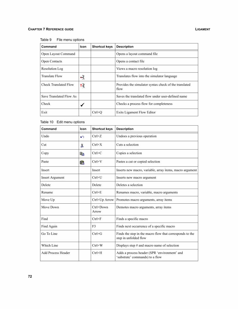
LIGAMENTCHAPTER 7 REFERENCE GUIDE
Command Icon Shortcut keys Description
Open Layout Command Opens a layout command file
Open Contacts Opens a contact file
Resolution Log Views a macro resolution log
Translate Flow Translates flow into the simulator language
Check Translated Flow Provides the simulator syntax check of the translated flow
Save Translated Flow As Saves the translated flow under user-defined name
Check Checks a process flow for completeness
Exit Ctrl+Q Exits Ligament Flow Editor
Table 10 Edit menu options
Command Icon Shortcut keys Description
Undo Ctrl+Z Undoes a previous operation
Cut Ctrl+X Cuts a selection
Copy Ctrl+C Copies a selection
Paste Ctrl+V Pastes a cut or copied selection
Insert Insert Inserts new macro, variable, array items, macro argument
Insert Argument Ctrl+U Inserts new macro argument
Delete Delete Deletes a selection
Rename Ctrl+E Renames macro, variable, macro arguments
Move Up Ctrl+Up Arrow Promotes macro arguments, array items
Move Down Ctrl+Down Arrow
Demotes macro arguments, array items
Find Ctrl+F Finds a specific macro
Find Again F3 Finds next occurrence of a specific macro
Go To Line Ctrl+G Finds the step in the macro flow that corresponds to the step in unfolded flow
Which Line Ctrl+W Displays step # and macro name of selection
Add Process Header Ctrl+H Adds a process header (SPR ‘environment’ and ‘substrate’ commands) to a flow
Table 9 File menu options
72
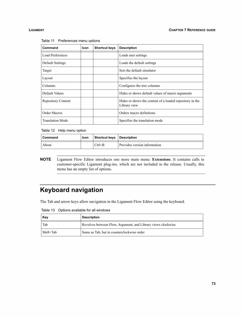
LIGAMENT CHAPTER 7 REFERENCE GUIDE
NOTE Ligament Flow Editor introduces one more main menu: Extensions. It contains calls tocustomer-specific Ligament plug-ins, which are not included in the release. Usually, thismenu has an empty list of options.
Keyboard navigationThe Tab and arrow keys allow navigation in the Ligament Flow Editor using the keyboard.
Table 11 Preferences menu options
Command Icon Shortcut keys Description
Load Preferences Loads user settings
Default Settings Loads the default settings
Target Sets the default simulator
Layout Specifies the layout
Columns Configures the tree columns
Default Values Hides or shows default values of macro arguments
Repository Content Hides or shows the content of a loaded repository in the Library view
Order Macros Orders macro definitions
Translation Mode Specifies the translation mode
Table 12 Help menu option
Command Icon Shortcut keys Description
About Ctrl+B Provides version information
Table 13 Options available for all windows
Key Description
Tab Revolves between Flow, Argument, and Library views clockwise
Shift+Tab Same as Tab, but in counterclockwise order
73
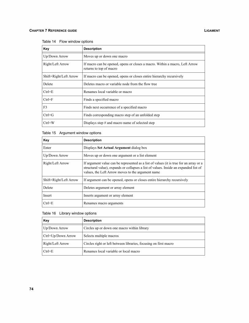
LIGAMENTCHAPTER 7 REFERENCE GUIDE
Table 14 Flow window options
Key Description
Up/Down Arrow Moves up or down one macro
Right/Left Arrow If macro can be opened, opens or closes a macro. Within a macro, Left Arrow returns to top of macro
Shift+Right/Left Arrow If macro can be opened, opens or closes entire hierarchy recursively
Delete Deletes macro or variable node from the flow tree
Ctrl+E Renames local variable or macro
Ctrl+F Finds a specified macro
F3 Finds next occurrence of a specified macro
Ctrl+G Finds corresponding macro step of an unfolded step
Ctrl+W Displays step # and macro name of selected step
Table 15 Argument window options
Key Description
Enter Displays Set Actual Argument dialog box
Up/Down Arrow Moves up or down one argument or a list element
Right/Left Arrow If argument value can be represented as a list of values (it is true for an array or a structural value), expands or collapses a list of values. Inside an expanded list of values, the Left Arrow moves to the argument name
Shift+Right/Left Arrow If argument can be opened, opens or closes entire hierarchy recursively
Delete Deletes argument or array element
Insert Inserts argument or array element
Ctrl+E Renames macro arguments
Table 16 Library window options
Key Description
Up/Down Arrow Circles up or down one macro within library
Ctrl+Up/Down Arrow Selects multiple macros
Right/Left Arrow Circles right or left between libraries, focusing on first macro
Ctrl+E Renames local variable or local macro
74
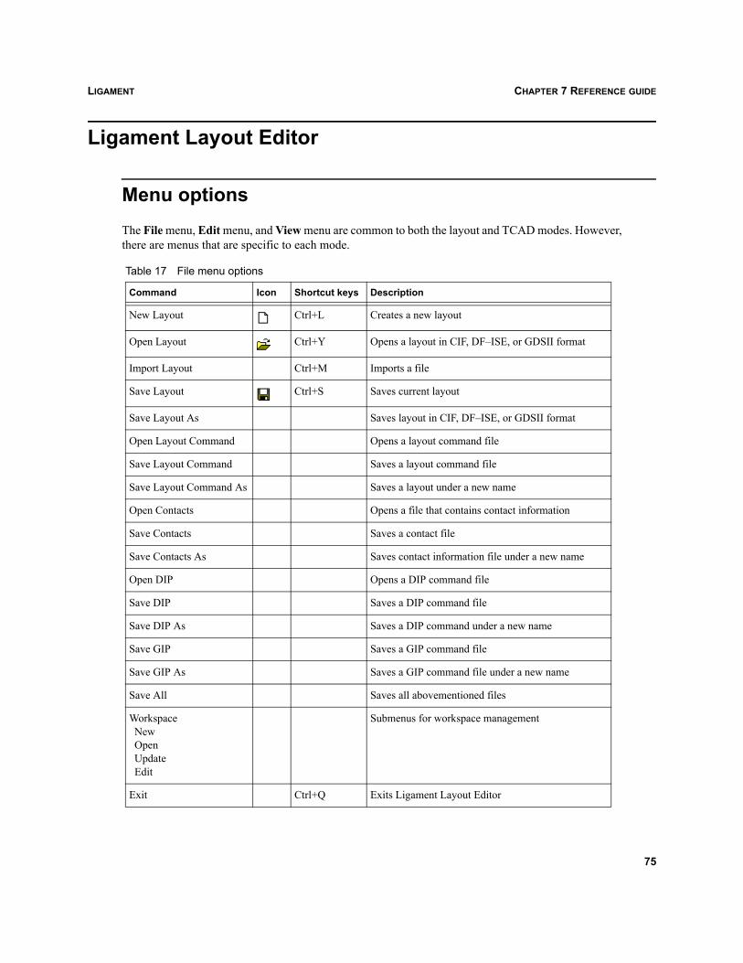
LIGAMENT CHAPTER 7 REFERENCE GUIDE
Ligament Layout Editor
Menu optionsThe File menu, Edit menu, and View menu are common to both the layout and TCAD modes. However,there are menus that are specific to each mode.
Table 17 File menu options
Command Icon Shortcut keys Description
New Layout Ctrl+L Creates a new layout
Open Layout Ctrl+Y Opens a layout in CIF, DF–ISE, or GDSII format
Import Layout Ctrl+M Imports a file
Save Layout Ctrl+S Saves current layout
Save Layout As Saves layout in CIF, DF–ISE, or GDSII format
Open Layout Command Opens a layout command file
Save Layout Command Saves a layout command file
Save Layout Command As Saves a layout under a new name
Open Contacts Opens a file that contains contact information
Save Contacts Saves a contact file
Save Contacts As Saves contact information file under a new name
Open DIP Opens a DIP command file
Save DIP Saves a DIP command file
Save DIP As Saves a DIP command under a new name
Save GIP Saves a GIP command file
Save GIP As Saves a GIP command file under a new name
Save All Saves all abovementioned files
WorkspaceNewOpenUpdateEdit
Submenus for workspace management
Exit Ctrl+Q Exits Ligament Layout Editor
75
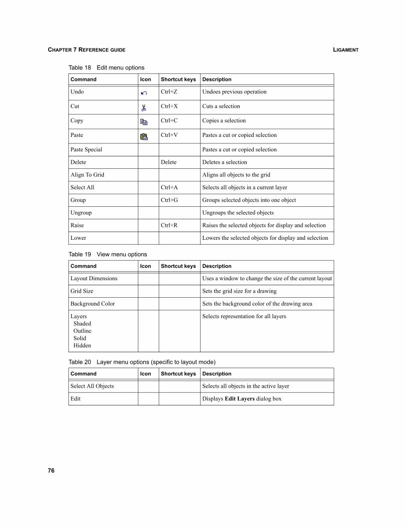
LIGAMENTCHAPTER 7 REFERENCE GUIDE
Table 18 Edit menu options
Command Icon Shortcut keys Description
Undo Ctrl+Z Undoes previous operation
Cut Ctrl+X Cuts a selection
Copy Ctrl+C Copies a selection
Paste Ctrl+V Pastes a cut or copied selection
Paste Special Pastes a cut or copied selection
Delete Delete Deletes a selection
Align To Grid Aligns all objects to the grid
Select All Ctrl+A Selects all objects in a current layer
Group Ctrl+G Groups selected objects into one object
Ungroup Ungroups the selected objects
Raise Ctrl+R Raises the selected objects for display and selection
Lower Lowers the selected objects for display and selection
Table 19 View menu options
Command Icon Shortcut keys Description
Layout Dimensions Uses a window to change the size of the current layout
Grid Size Sets the grid size for a drawing
Background Color Sets the background color of the drawing area
LayersShadedOutlineSolidHidden
Selects representation for all layers
Table 20 Layer menu options (specific to layout mode)
Command Icon Shortcut keys Description
Select All Objects Selects all objects in the active layer
Edit Displays Edit Layers dialog box
76
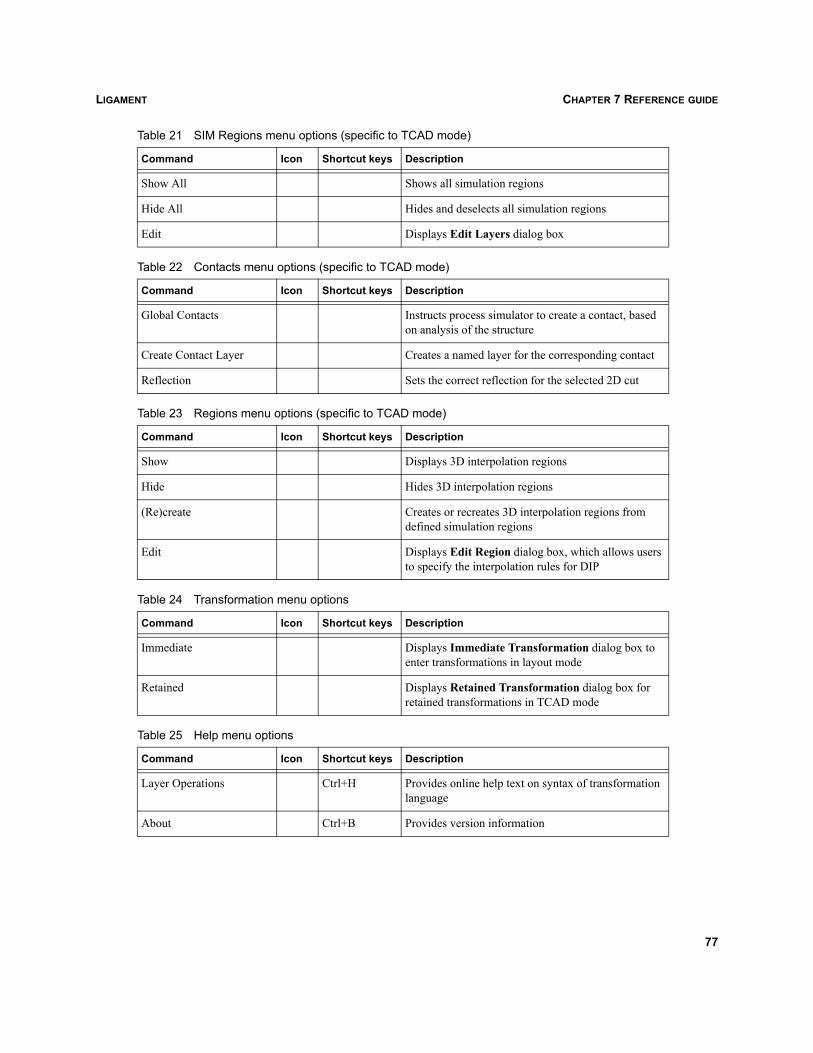
LIGAMENT CHAPTER 7 REFERENCE GUIDE
Table 21 SIM Regions menu options (specific to TCAD mode)
Command Icon Shortcut keys Description
Show All Shows all simulation regions
Hide All Hides and deselects all simulation regions
Edit Displays Edit Layers dialog box
Table 22 Contacts menu options (specific to TCAD mode)
Command Icon Shortcut keys Description
Global Contacts Instructs process simulator to create a contact, based on analysis of the structure
Create Contact Layer Creates a named layer for the corresponding contact
Reflection Sets the correct reflection for the selected 2D cut
Table 23 Regions menu options (specific to TCAD mode)
Command Icon Shortcut keys Description
Show Displays 3D interpolation regions
Hide Hides 3D interpolation regions
(Re)create Creates or recreates 3D interpolation regions from defined simulation regions
Edit Displays Edit Region dialog box, which allows users to specify the interpolation rules for DIP
Table 24 Transformation menu options
Command Icon Shortcut keys Description
Immediate Displays Immediate Transformation dialog box to enter transformations in layout mode
Retained Displays Retained Transformation dialog box for retained transformations in TCAD mode
Table 25 Help menu options
Command Icon Shortcut keys Description
Layer Operations Ctrl+H Provides online help text on syntax of transformation language
About Ctrl+B Provides version information
77
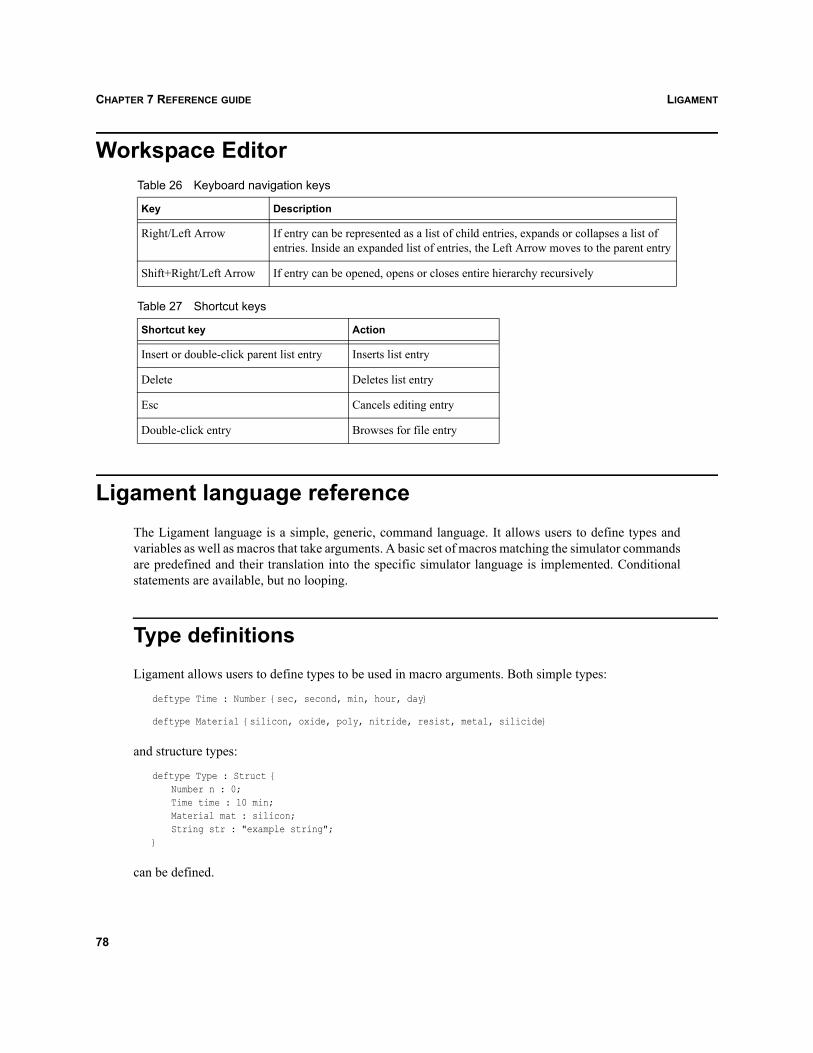
LIGAMENTCHAPTER 7 REFERENCE GUIDE
Workspace Editor
Ligament language referenceThe Ligament language is a simple, generic, command language. It allows users to define types andvariables as well as macros that take arguments. A basic set of macros matching the simulator commandsare predefined and their translation into the specific simulator language is implemented. Conditionalstatements are available, but no looping.
Type definitionsLigament allows users to define types to be used in macro arguments. Both simple types:
deftype Time : Number {sec, second, min, hour, day}
deftype Material {silicon, oxide, poly, nitride, resist, metal, silicide}
and structure types:
deftype Type : Struct {Number n : 0;Time time : 10 min;Material mat : silicon;String str : "example string";
}
can be defined.
Table 26 Keyboard navigation keys
Key Description
Right/Left Arrow If entry can be represented as a list of child entries, expands or collapses a list of entries. Inside an expanded list of entries, the Left Arrow moves to the parent entry
Shift+Right/Left Arrow If entry can be opened, opens or closes entire hierarchy recursively
Table 27 Shortcut keys
Shortcut key Action
Insert or double-click parent list entry Inserts list entry
Delete Deletes list entry
Esc Cancels editing entry
Double-click entry Browses for file entry
78
LIGAMENT CHAPTER 7 REFERENCE GUIDE
Two kinds of simple type are available: numeric (for example, type Time) and enumeration (for example,type Material). A set of possible units is included in the definition of a numeric type. Any variable of thistype must contain a unit.
Any variable of enumeration type can have one of the values defined in the corresponding typedefinition. No units are provided for enumeration types. The types String and Number are predefined asbasic types, which can be used to create new types.
A structure type consists of a number of fields of any predefined (for example, Number, String) or user-defined types (for example, Type). Structure types can be nested (one structure type can be included inother structure types).
In the following example, the structure type ANewType contains field type of type Type, that is, structuretype. The only restriction is that the structure type cannot contain a field of the same type, that is,structure types cannot be recursively nested:
deftype ANewType : Struct {String comment : "nested struct";Material mat : unknown;Number n : default;Type type : Struct {
n : 1;time : 20 sec;Material mat: poly;str : "example string 2";
};}
Fields of structure type can hold either a scalar value or an array of values. An array field can be of anypredefined or user-defined types such as numeric, enumeration, and structure. An array field can containan arbitrary number of items. Arrays are fully dynamic; no length restriction is predefined for arrays. Toindicate that the field will contain an array of values, use the indicator ‘{ }’ in the field definition. In thefollowing example, all fields of new structure type AnArrayType are array fields:
deftype AnArrayType : Struct {Number n{} : {};String str{} : { "string 1", "string 2", "string 3"};Time time{} : {11 sec, 20, 35 second, 40} min;Material mat{} : { silicon, oxide, silicon, oxide, silicon };Type type{} : {
Struct {n : 1;time : 10 sec;mat : metal;str : "example string 1";
},Struct {
n : 2;time : 20 min;mat : oxide;str : "example string 2";
},Struct {
n : 3;time : 30 hour;
79
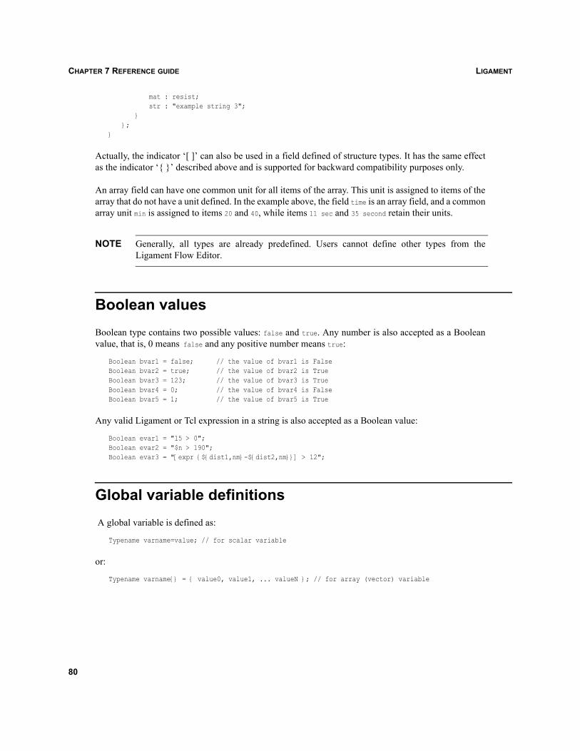
LIGAMENTCHAPTER 7 REFERENCE GUIDE
mat : resist;str : "example string 3";
}};
}
Actually, the indicator ‘[ ]’ can also be used in a field defined of structure types. It has the same effectas the indicator ‘{ }’ described above and is supported for backward compatibility purposes only.
An array field can have one common unit for all items of the array. This unit is assigned to items of thearray that do not have a unit defined. In the example above, the field time is an array field, and a commonarray unit min is assigned to items 20 and 40, while items 11 sec and 35 second retain their units.
NOTE Generally, all types are already predefined. Users cannot define other types from theLigament Flow Editor.
Boolean valuesBoolean type contains two possible values: false and true. Any number is also accepted as a Booleanvalue, that is, 0 means false and any positive number means true:
Boolean bvar1 = false; // the value of bvar1 is FalseBoolean bvar2 = true; // the value of bvar2 is TrueBoolean bvar3 = 123; // the value of bvar3 is TrueBoolean bvar4 = 0; // the value of bvar4 is FalseBoolean bvar5 = 1; // the value of bvar5 is True
Any valid Ligament or Tcl expression in a string is also accepted as a Boolean value:
Boolean evar1 = "15 > 0";Boolean evar2 = "$n > 190";Boolean evar3 = "[expr {${dist1,nm}-${dist2,nm}}] > 12";
Global variable definitions A global variable is defined as:
Typename varname=value; // for scalar variable
or:
Typename varname{} = { value0, value1, ... valueN }; // for array (vector) variable
80
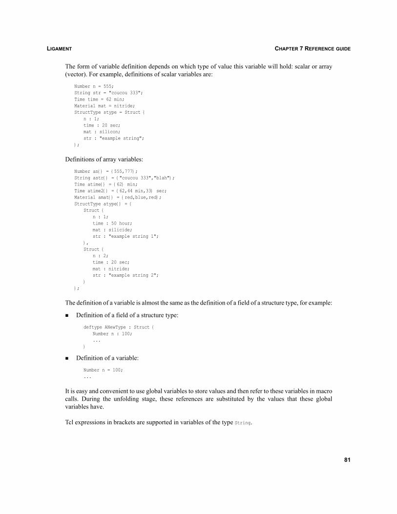
LIGAMENT CHAPTER 7 REFERENCE GUIDE
The form of variable definition depends on which type of value this variable will hold: scalar or array(vector). For example, definitions of scalar variables are:
Number n = 555;String str = "coucou 333";Time time = 62 min;Material mat = nitride;StructType stype = Struct {
n : 1;time : 20 sec;mat : silicon;str : "example string";
};
Definitions of array variables:
Number an{} = {555,777};String astr{} = {"coucou 333","blah"};Time atime{} = {62} min;Time atime2{} = {62,44 min,33} sec;Material amat{} = {red,blue,red};StructType atype{} = {
Struct {n : 1;time : 50 hour;mat : silicide;str : "example string 1";
},Struct {
n : 2;time : 20 sec;mat : nitride;str : "example string 2";
}};
The definition of a variable is almost the same as the definition of a field of a structure type, for example:
Definition of a field of a structure type:
deftype ANewType : Struct {Number n : 100;...
}
Definition of a variable:
Number n = 100;...
It is easy and convenient to use global variables to store values and then refer to these variables in macrocalls. During the unfolding stage, these references are substituted by the values that these globalvariables have.
Tcl expressions in brackets are supported in variables of the type String.
81
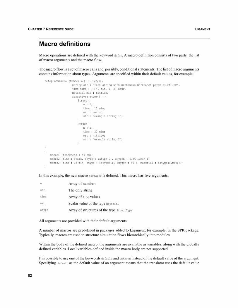
LIGAMENTCHAPTER 7 REFERENCE GUIDE
Macro definitionsMacro operations are defined with the keyword defop. A macro definition consists of two parts: the listof macro arguments and the macro flow.
The macro flow is a set of macro calls and, possibly, conditional statements. The list of macro argumentscontains information about types. Arguments are specified within their default values, for example:
defop newmacro (Number n{} : {1,2,3},String str : "test string with Sentaurus Workbench param @<GEN 1>@",Time time{} : {40 min, 1, 2} hour,Material mat : nitride,StructType atype{} : {
Struct {n : 1;time : 10 min;mat : resist;str : "example string 1";
},Struct {
n : 2;time : 20 min;mat : nitride;str : "example string 2";
}){
macro1 (thickness : 50 nm);macro2 (time : $time, stype : $atype(0), oxygen : 0.36 l/min);macro2 (time : 12 min, stype : $atype(1), oxygen : 99 %, material : $atype(0,mat));
}
In this example, the new macro newmacro is defined. This macro has five arguments:
All arguments are provided with their default arguments.
A number of macros are predefined in packages added to Ligament, for example, in the SPR package.Typically, macros are used to structure simulation flows hierarchically into modules.
Within the body of the defined macro, the arguments are available as variables, along with the globallydefined variables. Local variables defined inside the macro body are not supported.
It is possible to use one of the keywords default and unknown instead of the default value of the argument.Specifying default as the default value of an argument means that the translator uses the default value
n Array of numbersstr The only stringtime Array of Time valuesmat Scalar value of the type Materialatype Array of structures of the type StructType
82
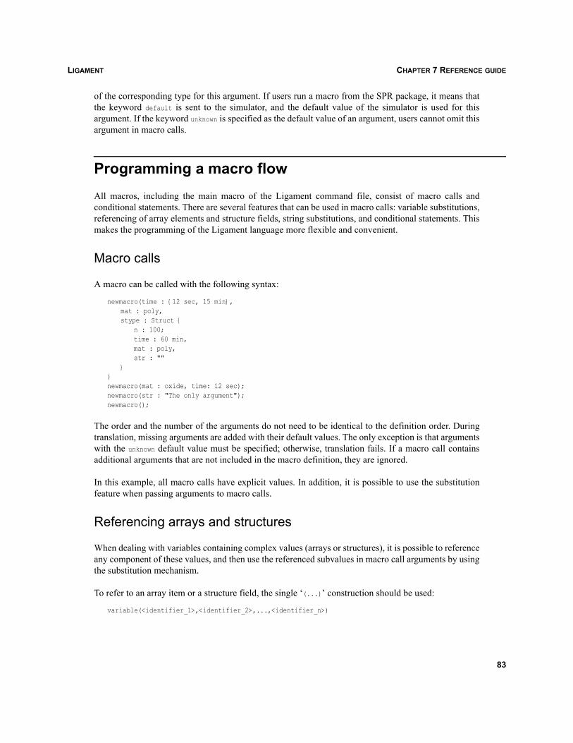
LIGAMENT CHAPTER 7 REFERENCE GUIDE
of the corresponding type for this argument. If users run a macro from the SPR package, it means thatthe keyword default is sent to the simulator, and the default value of the simulator is used for thisargument. If the keyword unknown is specified as the default value of an argument, users cannot omit thisargument in macro calls.
Programming a macro flowAll macros, including the main macro of the Ligament command file, consist of macro calls andconditional statements. There are several features that can be used in macro calls: variable substitutions,referencing of array elements and structure fields, string substitutions, and conditional statements. Thismakes the programming of the Ligament language more flexible and convenient.
Macro calls
A macro can be called with the following syntax:
newmacro(time : {12 sec, 15 min},mat : poly,stype : Struct {
n : 100;time : 60 min,mat : poly,str : ""
})newmacro(mat : oxide, time: 12 sec);newmacro(str : "The only argument");newmacro();
The order and the number of the arguments do not need to be identical to the definition order. Duringtranslation, missing arguments are added with their default values. The only exception is that argumentswith the unknown default value must be specified; otherwise, translation fails. If a macro call containsadditional arguments that are not included in the macro definition, they are ignored.
In this example, all macro calls have explicit values. In addition, it is possible to use the substitutionfeature when passing arguments to macro calls.
Referencing arrays and structures
When dealing with variables containing complex values (arrays or structures), it is possible to referenceany component of these values, and then use the referenced subvalues in macro call arguments by usingthe substitution mechanism.
To refer to an array item or a structure field, the single ‘(...)’ construction should be used:
variable(<identifier_1>,<identifier_2>,...,<identifier_n>)
83
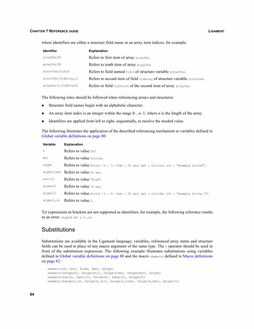
LIGAMENTCHAPTER 7 REFERENCE GUIDE
where identifiers are either a structure field name or an array item indices, for example:
The following rules should be followed when referencing arrays and structures:
Structure field names begin with an alphabetic character.
An array item index is an integer within the range 0…n–1, where n is the length of the array.
Identifiers are applied from left to right, sequentially, to resolve the needed value.
The following illustrates the application of the described referencing mechanism to variables defined inGlobal variable definitions on page 80:
Tcl expressions in brackets are not supported as identifiers, for example, the following reference resultsin an error: atype([set a 1],n).
Substitutions
Substitutions are available in the Ligament language; variables, referenced array items and structurefields can be used in place of any macro argument of the same type. The $ operator should be used infront of the substitution expression. The following example illustrates substitutions using variablesdefined in Global variable definitions on page 80 and the macro newmacro defined in Macro definitionson page 82:
newmacro($n, $str, $time, $mat, $stype)newmacro($stype(n), $stype(str), $stype(time), $stype(mat), $stype)newmacro($an(0), $astr(1), $atime(0), $amat(2), $atype(0))newmacro($atype(1,n), $atype(0,str), $atype(1,time), $atype(0,mat), $atype(1))
Identifier Explanation
arrayVar(0) Refers to first item of array arrayVar.arrayVar(9) Refers to tenth item of array arrayVar.structVar(fld14) Refers to field named fld14 of structure variable structVar.structVar(fldArray,1) Refers to second item of field fldArray of structure variable structVar.arrayVar(1,fldStruct) Refers to field fldStruct of the second item of array arrayVar.
Variable Explanation
n Refers to value 555.mat Refers to value nitride.stype Refers to value Struct {n : 1; time : 20 sec; mat : silicon; str : "example string"}.stype(time) Refers to value 20 sec.astr(1) Refers to value "blah".atime(2) Refers to value 33 sec.atype(1) Refers to value Struct {n : 2; time : 20 sec; mat : nitride; str : "example string 2"}.atype(1,n) Refers to value 2.
84
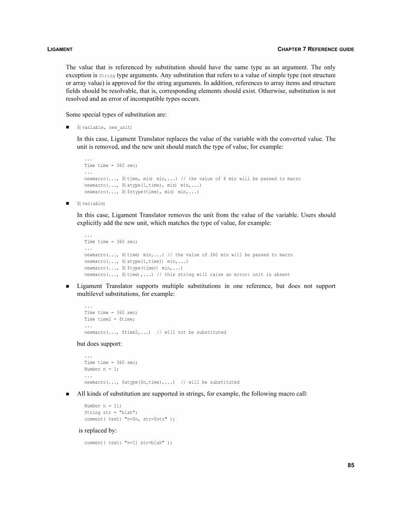
LIGAMENT CHAPTER 7 REFERENCE GUIDE
The value that is referenced by substitution should have the same type as an argument. The onlyexception is String type arguments. Any substitution that refers to a value of simple type (not structureor array value) is approved for the string arguments. In addition, references to array items and structurefields should be resolvable, that is, corresponding elements should exist. Otherwise, substitution is notresolved and an error of incompatible types occurs.
Some special types of substitution are:
${variable, new_unit}
In this case, Ligament Translator replaces the value of the variable with the converted value. Theunit is removed, and the new unit should match the type of value, for example:
...Time time = 360 sec;...newmacro(..., ${time, min} min,...) // the value of 6 min will be passed to macronewmacro(..., ${atype(1,time), min} min,...)newmacro(..., ${$stype(time), min} min,...)
${variable}
In this case, Ligament Translator removes the unit from the value of the variable. Users shouldexplicitly add the new unit, which matches the type of value, for example:
...Time time = 360 sec;...newmacro(..., ${time} min,...) // the value of 360 min will be passed to macronewmacro(..., ${atype(1,time)} min,...) newmacro(..., ${$type(time)} min,...) newmacro(..., ${time},...) // this string will raise an error: unit is absent
Ligament Translator supports multiple substitutions in one reference, but does not supportmultilevel substitutions, for example:
...Time time = 360 sec;Time time2 = $time;...newmacro(..., $time2,...) // will not be substituted
but does support:
...Time time = 360 sec;Number n = 1;...newmacro(..., $atype($n,time),...) // will be substituted
All kinds of substitution are supported in strings, for example, the following macro call:
Number n = 11;String str = "blah";comment( text: "n=$n, str=$str" );
is replaced by:
comment( text: "n=11 str=blah" );
85
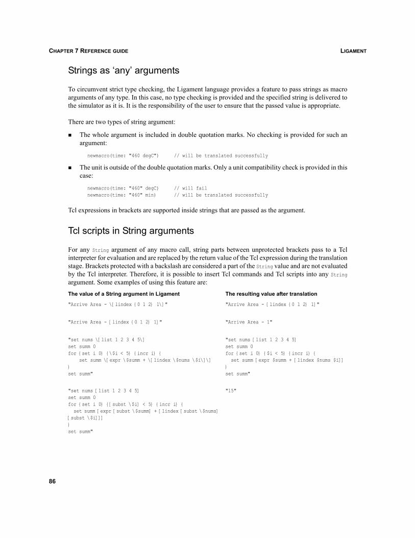
LIGAMENTCHAPTER 7 REFERENCE GUIDE
Strings as ‘any’ arguments
To circumvent strict type checking, the Ligament language provides a feature to pass strings as macroarguments of any type. In this case, no type checking is provided and the specified string is delivered tothe simulator as it is. It is the responsibility of the user to ensure that the passed value is appropriate.
There are two types of string argument:
The whole argument is included in double quotation marks. No checking is provided for such anargument:
newmacro(time: "460 degC") // will be translated successfully
The unit is outside of the double quotation marks. Only a unit compatibility check is provided in thiscase:
newmacro(time: "460" degC) // will failnewmacro(time: "460" min) // will be translated successfully
Tcl expressions in brackets are supported inside strings that are passed as the argument.
Tcl scripts in String arguments
For any String argument of any macro call, string parts between unprotected brackets pass to a Tclinterpreter for evaluation and are replaced by the return value of the Tcl expression during the translationstage. Brackets protected with a backslash are considered a part of the String value and are not evaluatedby the Tcl interpreter. Therefore, it is possible to insert Tcl commands and Tcl scripts into any Stringargument. Some examples of using this feature are:
The value of a String argument in Ligament The resulting value after translation
"Arrive Area - \[lindex {0 1 2} 1\]" "Arrive Area - [lindex {0 1 2} 1]"
"Arrive Area - [lindex {0 1 2} 1]" "Arrive Area - 1"
"set nums \[list 1 2 3 4 5\]set summ 0for {set i 0} {\$i < 5} {incr i} { set summ \[expr \$summ + \[lindex \$nums \$i\]\]}set summ"
"set nums [list 1 2 3 4 5]set summ 0for {set i 0} {$i < 5} {incr i} {
set summ [expr $summ + [lindex $nums $i]]}set summ"
"set nums [list 1 2 3 4 5]set summ 0for {set i 0} {[subst \$i] < 5} {incr i} {
set summ [expr [subst \$summ] + [lindex [subst \$nums] [subst \$i]]]}set summ"
"15"
86
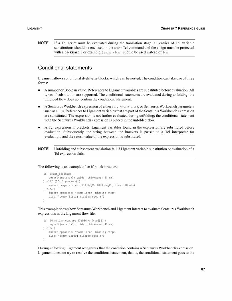
LIGAMENT CHAPTER 7 REFERENCE GUIDE
NOTE If a Tcl script must be evaluated during the translation stage, all entries of Tcl variablesubstitutions should be enclosed in the subst Tcl command and the $-sign must be protectedwith a backslash. For example, [subst \$var] should be used instead of $var.
Conditional statements
Ligament allows conditional if-elif-else blocks, which can be nested. The condition can take one of threeforms:
A number or Boolean value. References to Ligament variables are substituted before evaluation. Alltypes of substitution are supported. The conditional statements are evaluated during unfolding; theunfolded flow does not contain the conditional statement.
A Sentaurus Workbench expression of either @<...>@ or @[...]@, or Sentaurus Workbench parameterssuch as @...@. References to Ligament variables that are part of the Sentaurus Workbench expressionare substituted. The expression is not further evaluated during unfolding; the conditional statementwith the Sentaurus Workbench expression is placed in the unfolded flow.
A Tcl expression in brackets. Ligament variables found in the expression are substituted beforeevaluation. Subsequently, the string between the brackets is passed to a Tcl interpreter forevaluation, and the return value of the expression is substituted.
NOTE Unfolding and subsequent translation fail if Ligament variable substitution or evaluation of aTcl expression fails.
The following is an example of an if-block structure:
if ($fast_process) {deposit(material: oxide, thickness: 40 nm)
} elif ($full_process) {anneal(temperature: {900 degC, 1000 degC}, time: 10 min)
} else {insert(sprocess: "comm Error: missing step",dios: "comm('Error: missing step')")
}
This example shows how Sentaurus Workbench and Ligament interact to evaluate Sentaurus Workbenchexpressions in the Ligament flow file:
if (!@[string compare @TYPE@ c_Type2]@) {deposit(material: oxide, thickness: 40 nm)
} else {insert(sprocess: "comm Error: missing step",dios: "comm('Error: missing step')")
}
During unfolding, Ligament recognizes that the condition contains a Sentaurus Workbench expression.Ligament does not try to resolve the conditional statement, that is, the conditional statement goes to the
87
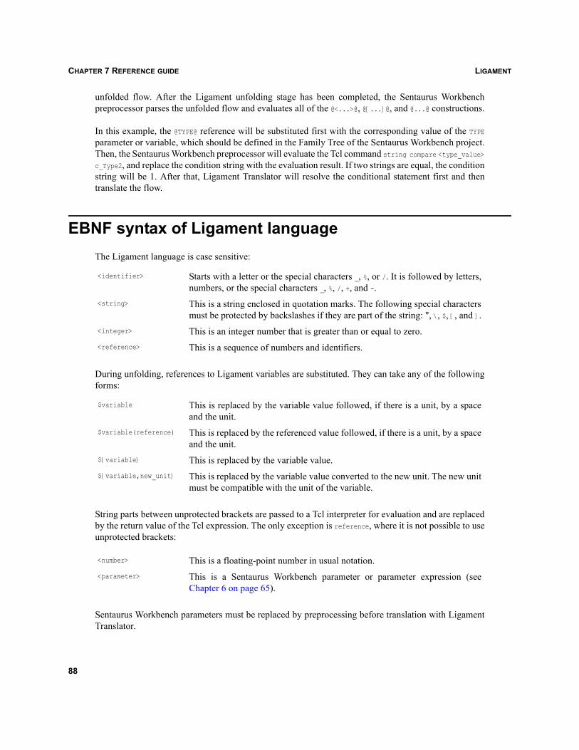
LIGAMENTCHAPTER 7 REFERENCE GUIDE
unfolded flow. After the Ligament unfolding stage has been completed, the Sentaurus Workbenchpreprocessor parses the unfolded flow and evaluates all of the @<...>@, @[...]@, and @...@ constructions.
In this example, the @TYPE@ reference will be substituted first with the corresponding value of the TYPEparameter or variable, which should be defined in the Family Tree of the Sentaurus Workbench project.Then, the Sentaurus Workbench preprocessor will evaluate the Tcl command string compare <type_value>c_Type2, and replace the condition string with the evaluation result. If two strings are equal, the conditionstring will be 1. After that, Ligament Translator will resolve the conditional statement first and thentranslate the flow.
EBNF syntax of Ligament languageThe Ligament language is case sensitive:
During unfolding, references to Ligament variables are substituted. They can take any of the followingforms:
String parts between unprotected brackets are passed to a Tcl interpreter for evaluation and are replacedby the return value of the Tcl expression. The only exception is reference, where it is not possible to useunprotected brackets:
Sentaurus Workbench parameters must be replaced by preprocessing before translation with LigamentTranslator.
<identifier> Starts with a letter or the special characters _, %, or /. It is followed by letters,numbers, or the special characters _, %, /, +, and -.
<string> This is a string enclosed in quotation marks. The following special charactersmust be protected by backslashes if they are part of the string: ", \, $, [, and ].
<integer> This is an integer number that is greater than or equal to zero.<reference> This is a sequence of numbers and identifiers.
$variable This is replaced by the variable value followed, if there is a unit, by a spaceand the unit.
$variable(reference) This is replaced by the referenced value followed, if there is a unit, by a spaceand the unit.
${variable} This is replaced by the variable value.${variable,new_unit} This is replaced by the variable value converted to the new unit. The new unit
must be compatible with the unit of the variable.
<number> This is a floating-point number in usual notation.<parameter> This is a Sentaurus Workbench parameter or parameter expression (see
Chapter 6 on page 65).
88
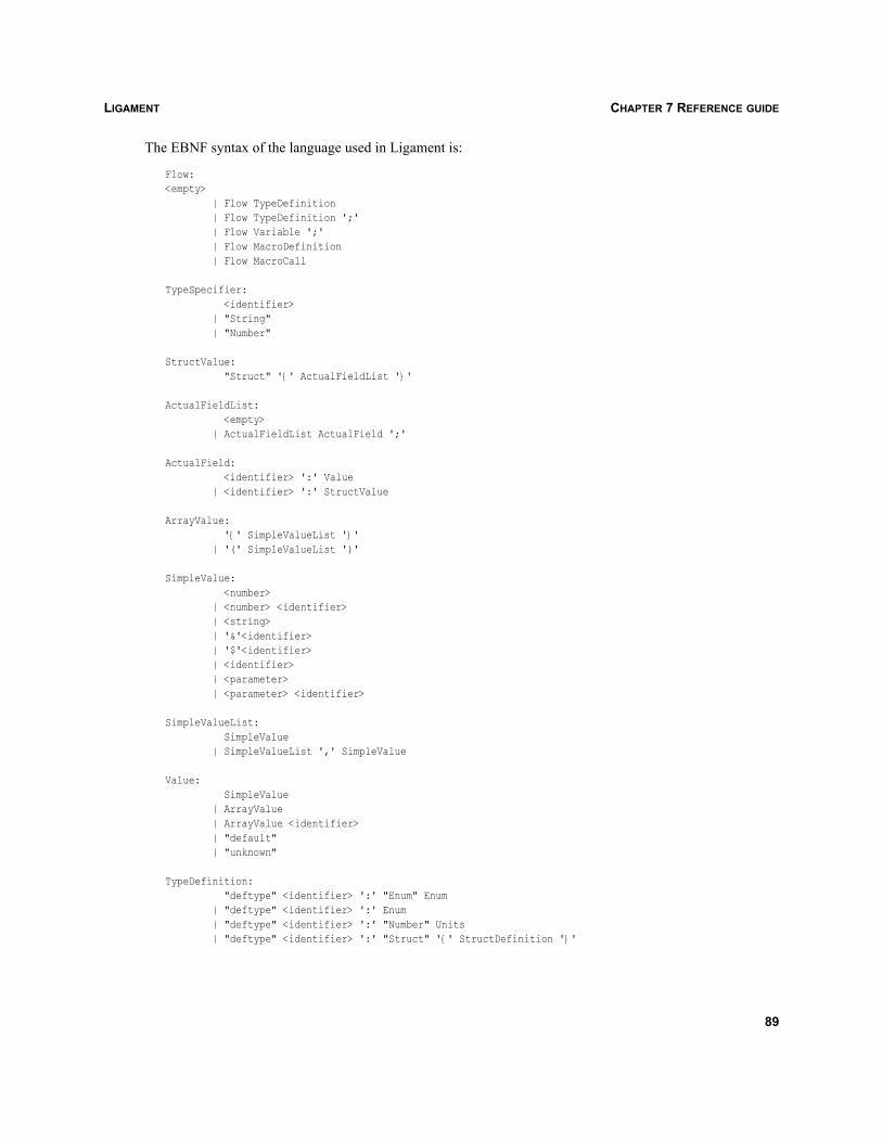
LIGAMENT CHAPTER 7 REFERENCE GUIDE
The EBNF syntax of the language used in Ligament is:
Flow:<empty> | Flow TypeDefinition | Flow TypeDefinition ';' | Flow Variable ';' | Flow MacroDefinition | Flow MacroCall
TypeSpecifier: <identifier> | "String" | "Number"
StructValue: "Struct" '{' ActualFieldList '}'
ActualFieldList: <empty> | ActualFieldList ActualField ';'
ActualField: <identifier> ':' Value | <identifier> ':' StructValue
ArrayValue: '{' SimpleValueList '}' | '(' SimpleValueList ')'
SimpleValue: <number> | <number> <identifier> | <string> | '&'<identifier> | '$'<identifier> | <identifier> | <parameter> | <parameter> <identifier>
SimpleValueList: SimpleValue | SimpleValueList ',' SimpleValue
Value: SimpleValue | ArrayValue | ArrayValue <identifier> | "default" | "unknown"
TypeDefinition: "deftype" <identifier> ':' "Enum" Enum | "deftype" <identifier> ':' Enum | "deftype" <identifier> ':' "Number" Units | "deftype" <identifier> ':' "Struct" '{' StructDefinition '}'
89
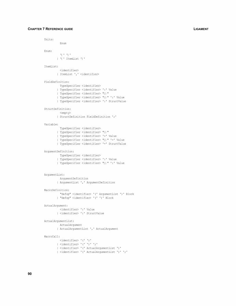
LIGAMENTCHAPTER 7 REFERENCE GUIDE
Units: Enum
Enum: '{' '}' | '{' ItemList '}'
ItemList: <identifier> | ItemList ',' <identifier>
FieldDefinition: TypeSpecifier <identifier> | TypeSpecifier <identifier> ':' Value | TypeSpecifier <identifier> "{}" | TypeSpecifier <identifier> "{}" ':' Value | TypeSpecifier <identifier> ':' StructValue
StructDefinition: <empty> | StructDefinition FieldDefinition ';'
Variable: TypeSpecifier <identifier> | TypeSpecifier <identifier> "{}" | TypeSpecifier <identifier> '=' Value | TypeSpecifier <identifier> "{}" '=' Value | TypeSpecifier <identifier> '=' StructValue
ArgumentDefinition: TypeSpecifier <identifier> | TypeSpecifier <identifier> ':' Value | TypeSpecifier <identifier> "{}" ':' Value
ArgumentList: ArgumentDefinition | ArgumentList ',' ArgumentDefinition
MacroDefinition: "defop" <identifier> '(' ArgumentList ')' Block | "defop" <identifier> '(' ')' Block
ActualArgument: <identifier> ':' Value | <identifier> ':' StructValue
ActualArgumentList: ActualArgument | ActualArgumentList ',' ActualArgument
MacroCall: <identifier> '(' ')' | <identifier> '(' ')' ';' | <identifier> '(' ActualArgumentList ')' | <identifier> '(' ActualArgumentList ')' ';'
90
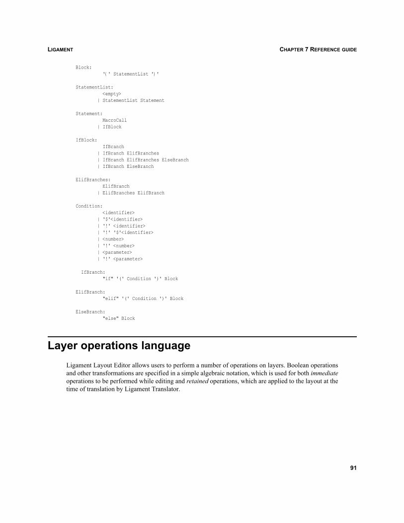
LIGAMENT CHAPTER 7 REFERENCE GUIDE
Block: '{' StatementList '}'
StatementList: <empty> | StatementList Statement
Statement: MacroCall | IfBlock
IfBlock: IfBranch | IfBranch ElifBranches | IfBranch ElifBranches ElseBranch | IfBranch ElseBranch
ElifBranches: ElifBranch | ElifBranches ElifBranch
Condition: <identifier> | '$'<identifier> | '!' <identifier> | '!' '$'<identifier> | <number> | '!' <number> | <parameter> | '!' <parameter>
IfBranch: "if" '(' Condition ')' Block
ElifBranch: "elif" '(' Condition ')' Block
ElseBranch: "else" Block
Layer operations languageLigament Layout Editor allows users to perform a number of operations on layers. Boolean operationsand other transformations are specified in a simple algebraic notation, which is used for both immediateoperations to be performed while editing and retained operations, which are applied to the layout at thetime of translation by Ligament Translator.
91
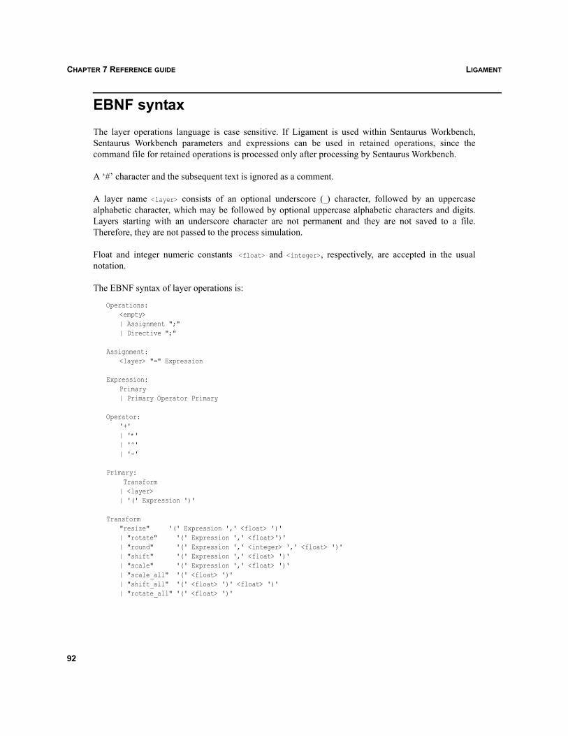
LIGAMENTCHAPTER 7 REFERENCE GUIDE
EBNF syntaxThe layer operations language is case sensitive. If Ligament is used within Sentaurus Workbench,Sentaurus Workbench parameters and expressions can be used in retained operations, since thecommand file for retained operations is processed only after processing by Sentaurus Workbench.
A ‘#’ character and the subsequent text is ignored as a comment.
A layer name <layer> consists of an optional underscore (_) character, followed by an uppercasealphabetic character, which may be followed by optional uppercase alphabetic characters and digits.Layers starting with an underscore character are not permanent and they are not saved to a file.Therefore, they are not passed to the process simulation.
Float and integer numeric constants <float> and <integer>, respectively, are accepted in the usualnotation.
The EBNF syntax of layer operations is:
Operations:<empty>| Assignment ";"| Directive ";"
Assignment:<layer> "=" Expression
Expression:Primary| Primary Operator Primary
Operator:'+'| '*'| '^'| '-'
Primary: Transform| <layer>| '(' Expression ')'
Transform "resize" '(' Expression ',' <float> ')'| "rotate" '(' Expression ',' <float>')'| "round" '(' Expression ',' <integer> ',' <float> ')'| "shift" '(' Expression ',' <float> ')'| "scale" '(' Expression ',' <float> ')'| "scale_all" '(' <float> ')'| "shift_all" '(' <float> ')' <float> ')'| "rotate_all" '(' <float> ')'
92
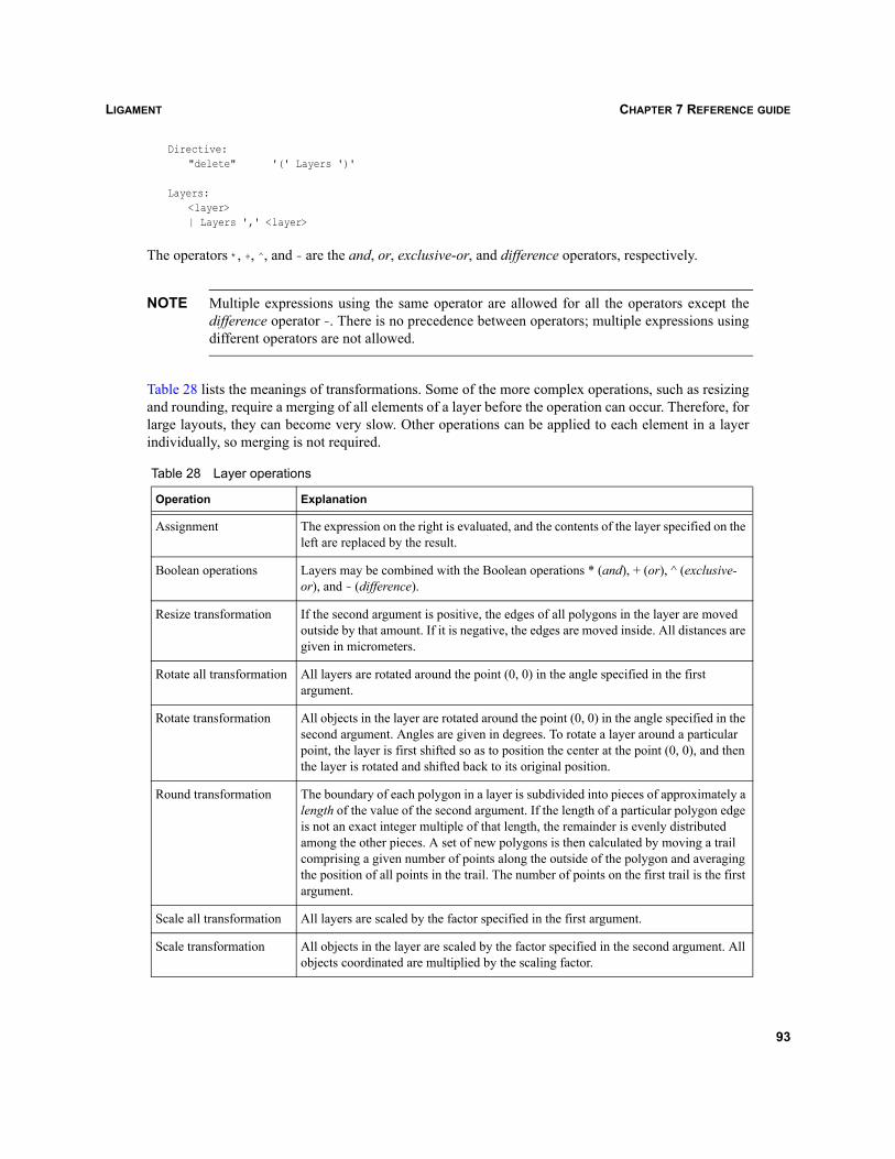
LIGAMENT CHAPTER 7 REFERENCE GUIDE
Directive:"delete" '(' Layers ')'
Layers:<layer>| Layers ',' <layer>
The operators *, +, ^, and - are the and, or, exclusive-or, and difference operators, respectively.
NOTE Multiple expressions using the same operator are allowed for all the operators except thedifference operator -. There is no precedence between operators; multiple expressions usingdifferent operators are not allowed.
Table 28 lists the meanings of transformations. Some of the more complex operations, such as resizingand rounding, require a merging of all elements of a layer before the operation can occur. Therefore, forlarge layouts, they can become very slow. Other operations can be applied to each element in a layerindividually, so merging is not required.
Table 28 Layer operations
Operation Explanation
Assignment The expression on the right is evaluated, and the contents of the layer specified on the left are replaced by the result.
Boolean operations Layers may be combined with the Boolean operations * (and), + (or), ^ (exclusive-or), and - (difference).
Resize transformation If the second argument is positive, the edges of all polygons in the layer are moved outside by that amount. If it is negative, the edges are moved inside. All distances are given in micrometers.
Rotate all transformation All layers are rotated around the point (0, 0) in the angle specified in the first argument.
Rotate transformation All objects in the layer are rotated around the point (0, 0) in the angle specified in the second argument. Angles are given in degrees. To rotate a layer around a particular point, the layer is first shifted so as to position the center at the point (0, 0), and then the layer is rotated and shifted back to its original position.
Round transformation The boundary of each polygon in a layer is subdivided into pieces of approximately a length of the value of the second argument. If the length of a particular polygon edge is not an exact integer multiple of that length, the remainder is evenly distributed among the other pieces. A set of new polygons is then calculated by moving a trail comprising a given number of points along the outside of the polygon and averaging the position of all points in the trail. The number of points on the first trail is the first argument.
Scale all transformation All layers are scaled by the factor specified in the first argument.
Scale transformation All objects in the layer are scaled by the factor specified in the second argument. All objects coordinated are multiplied by the scaling factor.
93
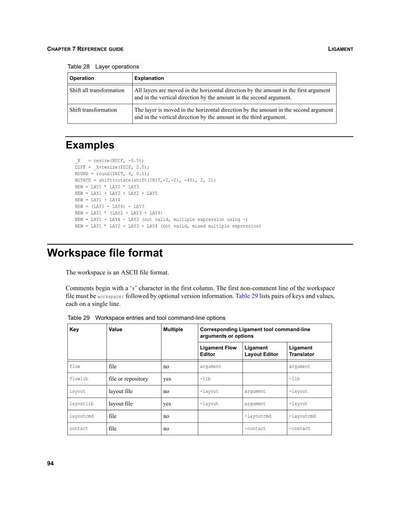
LIGAMENTCHAPTER 7 REFERENCE GUIDE
Examples_X = resize(NDIF, -0.5);DIFF = _X+resize(PDIF, 2.0);ROUND = round(INIT, 4, 0.1);ROTATE = shift(rotate(shift(INIT,-2,-2), -45), 2, 2);NEW = LAY1 * LAY2 * LAY3NEW = LAY1 + LAY3 + LAY2 + LAY5NEW = LAY1 - LAY4NEW = (LAY1 - LAY4) - LAY3NEW = LAY1 * (LAY2 + LAY3 + LAY4)NEW = LAY1 - LAY4 - LAY3 (not valid, multiple expression using -)NEW = LAY1 * LAY2 + LAY3 + LAY4 (not valid, mixed multiple expression)
Workspace file formatThe workspace is an ASCII file format.
Comments begin with a ‘#’ character in the first column. The first non-comment line of the workspacefile must be workspace: followed by optional version information. Table 29 lists pairs of keys and values,each on a single line.
Shift all transformation All layers are moved in the horizontal direction by the amount in the first argument and in the vertical direction by the amount in the second argument.
Shift transformation The layer is moved in the horizontal direction by the amount in the second argument and in the vertical direction by the amount in the third argument.
Table 29 Workspace entries and tool command-line options
Key Value Multiple Corresponding Ligament tool command-line arguments or options
Ligament Flow Editor
Ligament Layout Editor
Ligament Translator
flow file no argument argument
flowlib file or repository yes -lib -lib
layout layout file no -layout argument -layout
layoutlib layout file yes -layout argument -layout
layoutcmd file no -layoutcmd -layoutcmd
contact file no -contact -contact
Table 28 Layer operations
Operation Explanation
94
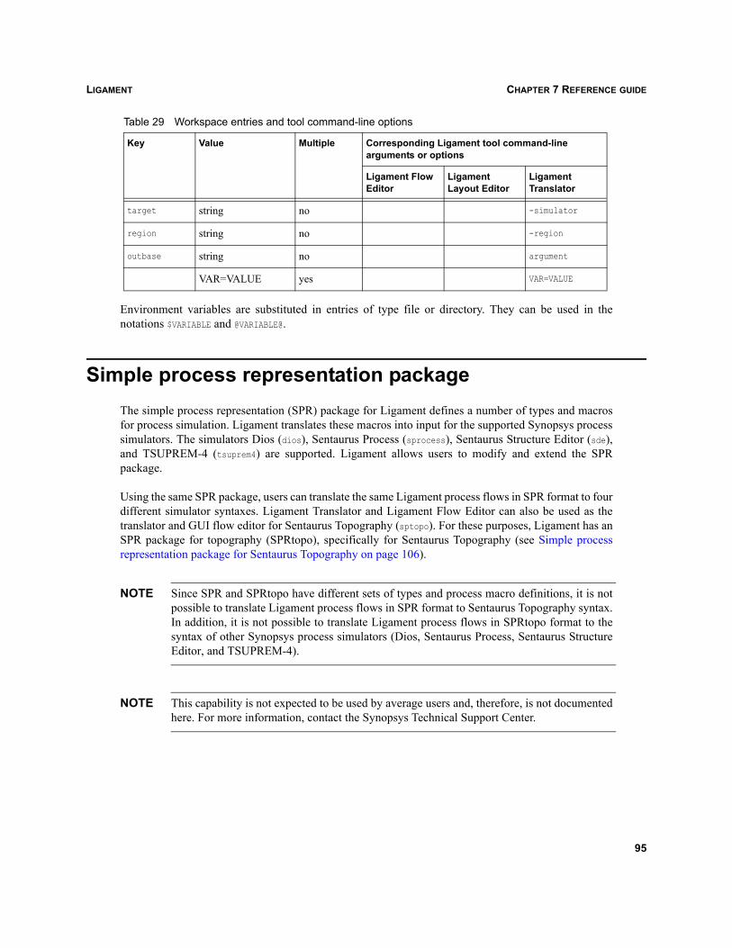
LIGAMENT CHAPTER 7 REFERENCE GUIDE
Environment variables are substituted in entries of type file or directory. They can be used in thenotations $VARIABLE and @VARIABLE@.
Simple process representation packageThe simple process representation (SPR) package for Ligament defines a number of types and macrosfor process simulation. Ligament translates these macros into input for the supported Synopsys processsimulators. The simulators Dios (dios), Sentaurus Process (sprocess), Sentaurus Structure Editor (sde),and TSUPREM-4 (tsuprem4) are supported. Ligament allows users to modify and extend the SPRpackage.
Using the same SPR package, users can translate the same Ligament process flows in SPR format to fourdifferent simulator syntaxes. Ligament Translator and Ligament Flow Editor can also be used as thetranslator and GUI flow editor for Sentaurus Topography (sptopo). For these purposes, Ligament has anSPR package for topography (SPRtopo), specifically for Sentaurus Topography (see Simple processrepresentation package for Sentaurus Topography on page 106).
NOTE Since SPR and SPRtopo have different sets of types and process macro definitions, it is notpossible to translate Ligament process flows in SPR format to Sentaurus Topography syntax.In addition, it is not possible to translate Ligament process flows in SPRtopo format to thesyntax of other Synopsys process simulators (Dios, Sentaurus Process, Sentaurus StructureEditor, and TSUPREM-4).
NOTE This capability is not expected to be used by average users and, therefore, is not documentedhere. For more information, contact the Synopsys Technical Support Center.
target string no -simulator
region string no -region
outbase string no argument
VAR=VALUE yes VAR=VALUE
Table 29 Workspace entries and tool command-line options
Key Value Multiple Corresponding Ligament tool command-line arguments or options
Ligament Flow Editor
Ligament Layout Editor
Ligament Translator
95
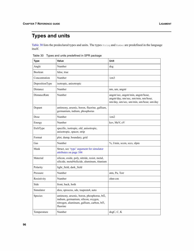
LIGAMENTCHAPTER 7 REFERENCE GUIDE
Types and unitsTable 30 lists the predeclared types and units. The types String and Number are predefined in the languageitself.
Table 30 Types and units predefined in SPR package
Type Value Unit
Angle Number deg
Boolean false, true
Concentration Number /cm3
DepositionType isotropic, anisotropic
Distance Number nm, um, angstr
DistanceRate Number angstr/sec, angstr/min, angstr/hour,angstr/day, nm/sec, nm/min, nm/hour,nm/day, um/sec, um/min, um/hour, um/day
Dopant antimony, arsenic, boron, fluorine, gallium, germanium, indium, phosphorus
Dose Number /cm2
Energy Number kev, MeV, eV
EtchType specific, isotropic, old_anisotropic, anisotropic, spacer, strip
Format plot, dump, boundary, grid
Gas Number %, l/min, sccm, sccs, slpm
Mask Struct, see ‘type’ argument for simulator attributes on page 104
Material silicon, oxide, poly, nitride, resist, metal, silicide, metal4silicide, aluminum, titanium
Polarity light_field, dark_field
Pressure Number atm, Pa, Torr
Resistivity Number ohm-cm
Side front, back, both
Simulator dios, sprocess, sde, tsuprem4, auto
Species antimony, arsenic, boron, phosphorus, bf2, indium, germanium, silicon, oxygen, nitrogen, aluminum, gallium, carbon, bf3, fluorine
Temperature Number degC, C, K
96
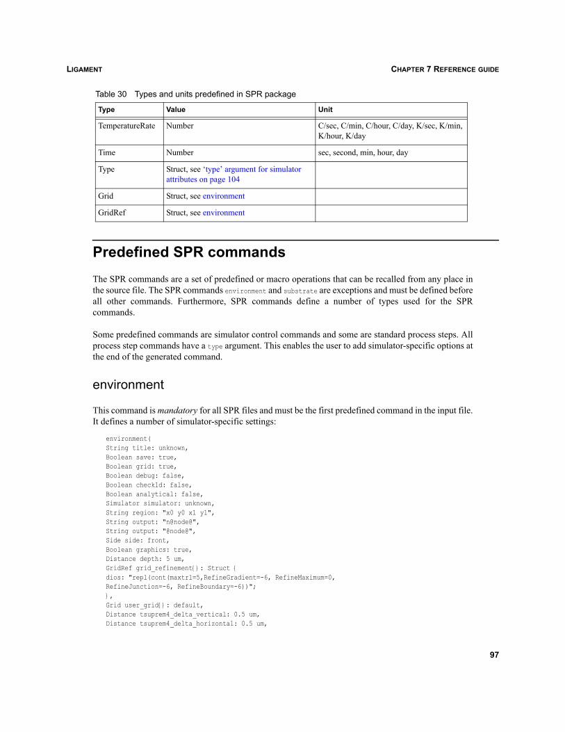
LIGAMENT CHAPTER 7 REFERENCE GUIDE
Predefined SPR commandsThe SPR commands are a set of predefined or macro operations that can be recalled from any place inthe source file. The SPR commands environment and substrate are exceptions and must be defined beforeall other commands. Furthermore, SPR commands define a number of types used for the SPRcommands.
Some predefined commands are simulator control commands and some are standard process steps. Allprocess step commands have a type argument. This enables the user to add simulator-specific options atthe end of the generated command.
environment
This command is mandatory for all SPR files and must be the first predefined command in the input file.It defines a number of simulator-specific settings:
environment(String title: unknown,Boolean save: true,Boolean grid: true,Boolean debug: false,Boolean check1d: false,Boolean analytical: false,Simulator simulator: unknown,String region: "x0 y0 x1 y1",String output: "n@node@",String output: "@node@",Side side: front,Boolean graphics: true,Distance depth: 5 um,GridRef grid_refinement{}: Struct {dios: "repl(cont(maxtrl=5,RefineGradient=-6, RefineMaximum=0,RefineJunction=-6, RefineBoundary=-6))";},Grid user_grid{}: default,Distance tsuprem4_delta_vertical: 0.5 um,Distance tsuprem4_delta_horizontal: 0.5 um,
Type Value Unit
TemperatureRate Number C/sec, C/min, C/hour, C/day, K/sec, K/min, K/hour, K/day
Time Number sec, second, min, hour, day
Type Struct, see ‘type’ argument for simulator attributes on page 104
Grid Struct, see environment
GridRef Struct, see environment
Table 30 Types and units predefined in SPR package
97
LIGAMENTCHAPTER 7 REFERENCE GUIDE
Distance tsuprem4_min_vertical: 0.1 um,Distance tsuprem4_min_horizontal: 0.1 um)
NOTE The output argument or output file command-line argument should not exceed six characterswhen using this option.
title Used as information for command file titles.save If set to true, a save command is automatically added at the end of the simulator
input file.grid (Dios, Sentaurus Process only) If set to true, a grid generation command for
Mdraw or Mesh is added at the end of the simulator input file.check1d (Dios, Sentaurus Process only) If set to true, two 1D cuts at the ends of the 2D
simulation regions are automatically stored.
analytical Not used; for backward compatibility only.simulator A simulator can be specified. By default, the Synopsys simulators Dios, Sentaurus
Process, Sentaurus Structure Editor, and TSUPREM-4 are supported. It is possibleto add further simulators. For more information, contact the Synopsys TechnicalSupport Center.
region Either a layer name of a simulation region from the Ligament Layout Editor (SIM1D,SIM2D, SIM3D …), or coordinates. When a layer name is specified, Ligament toolsautomatically recognize the type of the simulation (1D, 2D, or 3D). If coordinatesare given explicitly, the recognition is based on the number of points specified:– 1D simulation: The coordinates of the simulation point (two numbers), forexample: "0.0 0.0".– 2D simulation: The coordinates of two points (four numbers). These pointsrepresent the ends of the simulation region, for example: "0.0 0.0 2.0 5.0".– 3D simulation (Sentaurus Process only): The coordinates of two points (fournumbers) and the special flag "3D". The points represent the coordinates of twodiagonally opposite corners, for example: "0.0 0.0 2.0 5.0 3D".
output Base or root name for the generated simulator input files.node Node number. The default value @node@ is replaced with the real node number
during preprocessing in Sentaurus Workbench. This node number is used in thetranslation to Sentaurus Process to keep unique enumeration for machines,temperature ramps, and so on.
graphics (Dios, Sentaurus Process only) If set to true, the Dios graphics window is switchedon during simulation. In the case of a Sentaurus Process translation, the graphics on
command is generated.depth Depth of the simulation region.
98
LIGAMENT CHAPTER 7 REFERENCE GUIDE
A number of additional commands support the grid generation for TSUPREM-4.
substrate
The substrate command specifies the substrate material. It is mandatory and must be called once,immediately after environment. Only calls to the insert and comment commands are permitted betweenenvironment and substrate.
substrate( Dopant dopant : unknown,Concentration concentration : 0/cm3,Resistivity resistivity : 0 ohm-cm,Number orientation : 100,Type type{} : default)
For example, to initialize the simulation domain with a silicon layer, either concentration or resistivitymust be specified:
substrate(dopant: boron, resistivity: 20 ohm-cm)
comment
This operation is used to insert comments into the target simulator input file:
comment ( String text: "")
grid_refinement (Dios, Sentaurus Process only) Contains standard settings for a grid refinement,independent of simulator. Users can overwrite it with their own grid refinementstring. The type GridRef is defined in SPR:
deftype GridRef : Struct {String dios : "";String sprocess : "";String sde : "";String tsuprem4 : "";
}
user_grid (Dios, Sentaurus Process only) If empty, Ligament generates the default gridcommand for the simulation region. Users can define their own grid string, whichwill replace the default grid command. In this case, users are responsible for thecompleteness of the grid. A user-defined grid can be specified for each simulatorindependently. The type Grid is defined in SPR:
deftype Grid : Struct {String dios : "";String sprocess : "";String sde : "";String tsuprem4 : "";
}
99
LIGAMENTCHAPTER 7 REFERENCE GUIDE
remark
This operation is used to insert remarks into the target simulator input file:
remark ( String text: "")
The remark operation is very close to the comment operation, but these operations can have differentrepresentation in the flow translated to the target simulator language. For example, for the Dioslanguage, the remark operation is translated to a Dios comment string, but the comment operation istranslated to a Dios comment string and a Dios comment statement.
insert
This operation is used to insert simulator-specific commands in the simulator language directly into thesimulator input file. In addition, preprocessor commands for Sentaurus Workbench can be given:
insert( String dios : "",String sprocess : "",String sde : "",String tsuprem4 : "")
load
This operation loads a complete device from a previously saved simulation. The substrate command isignored:
load( String basename : "",String dios : "",String sprocess : "",String sde : "",String tsuprem4 : "")
save
This operation saves current simulation results to a plot or dump file, or generates a grid or boundaryfile in TDR or DF–ISE format. If the environmental variable TDRMODE exists and is set to "false", the DF–ISE format is used for the generation of a grid or boundary file. Otherwise, the TDR format is used:
save( String basename : "",Format format : dump,String dios : "",String sprocess : "",String sde : "",String tsuprem4 : "")
100
LIGAMENT CHAPTER 7 REFERENCE GUIDE
anneal
This operation is used to simulate standard annealing and oxidation operations:
anneal( Time time{} : unknown,Temperature temperature{} : 900 deg C,Pressure pressure : 1 atm,Gas nitrogen : 3 l/min,Gas hydrogen : 0 l/min,Gas oxygen : 0 l/min,Gas hcl : 0 l/min,Temperature steam_temperature : 0 degC,Gas watersteam : 0 %,Gas pyrosteam : 0 %,Side side : both,Type type{} : default)
Time and temperature must be supplied and the default atmosphere (ambient temperature) is inert. Bothtime and temperature can be a fixed value or intervals. A fixed temperature is indicated with one timevalue and one temperature value. A linear ramp is given with one time value and two temperature values.Arbitrary, linearly interpolated, ramp shapes can be indicated with arrays for both time and temperature,where the time values are the intervals for each linear part, and temperature values are at the beginningand end of each linear part, respectively. Therefore, the number of time values must be one less than thenumber of temperature values.
The concentration of gases can be specified either as a percentage, for example, a partial concentration(in percent), as a gas flow in l/minute (liters per minute), or as a pressure corrected gas flow in sccm(standard cubic centimeters per minute) or slm (standard liters per minute). Partial concentrations andflows cannot be mixed; either notation must be used for all gases, except if the corresponding gas flowor partial concentration is zero. An inert annealing step is assumed as a default.
NOTE The watersteam, steam_temperature, and pyrosteam arguments are obsolete and are present forbackward compatibility only. Use gas flows instead.
If gases are specified as flows, the values are directly passed to the simulator. This is recommended.
Partial gas concentrations are supported for Dios only. The concentrations are translated to atmosphere[atm]. Refer to the Dios manual for handling of the corresponding atmospheres. The atmospheres areobtained as follows:
Pyrogenic steam This is achieved when hydrogen and oxygen fluxes or concentrations are greaterthan 0.
Wet oxidation This is performed when the water steam temperature is greater than 0oC.
Dry oxidation with HClThis is performed when the HCl flux or concentration is greater than 0.
101
LIGAMENTCHAPTER 7 REFERENCE GUIDE
Dry oxidation This is performed when the HCl flux or concentration is greater than 0. The gaspressure must be specified when nitrogen is not added.
Inert gas This is used as the default.
An example is:
anneal( temperature: $temperature, time: 15 min,oxygen: 0.2 l/min, nitrogen: 5 l/min)
anneal(time: 30 min, temperature: {1000,900} degC)
deposit
This operation is used to simulate material deposition operations. If the thickness is not given, simulator-dependent options must be added to define the deposition rate and time:
deposit(Material material : unknown,Distance thickness : unknown,Dopant dopant : default,Concentration concentration : default,Side side : both,DepositionType deposition_type: isotropic,Type type{} : default)
An example is:
deposit(material: nitride, thickness: 1600 angstr)
epitaxy
This operation simulates the growth of epitaxial layers:
epitaxy(Time time : unknown,Temperature temperature : unknown,Distance thickness : unknown,Dopant dopant : unknown,Concentration concentration : unknownSide side : frontType type{} : default)
Only a single temperature and time value are accepted, for example:
epitaxy(time: 25 min, thickness: 7 um,temperature: 1000 degC, dopant: phosphorus,concentration: 1e15 /cm3)
etch
This operation simulates the etching of materials:
etch( Material material{} : unknown,Distance thickness{} : default,EtchType etch_type : specific,
102
LIGAMENT CHAPTER 7 REFERENCE GUIDE
Number overetch : 0,Material etchstop{} : default,String mat_coeffs{} : default,String beam_direction{} : "1 0 0",Number beam_factor{} : 1,Time time : 1.0 min, Side side : both,Type type{} : default)
The arguments etch_type and overetch are considered for Dios and Sentaurus Process only. The argumentetch_type selects settings appropriate to obtain the effect of isotropic, anisotropic, spacer, strip, andFourier etching. The value old_anisotropic is obsolete and should not be used. The value specific isprovided to give users flexibility. In this case, the user must specify the etching type and other necessarysettings by using the type argument.
The argument overetch is an additional amount of etching, given in percent, of the resulting etchingdepth. In most simulators, etching is an empirical, geometrically modeled operation. To obtainphysically correct behavior, a number of simulator-specific etching parameters must be set. In this case,it is recommended to specify the specific or default etch type. This uses the arguments material andoveretch. Simulator-specific parameters for etching and angle dependency, and other parameters can beadded in the Type statement. The complete material layer is removed when default etching, withoutadditional Type statements, is used.
If thickness is not given, simulator-dependent options must be added to define the etching rate and time,for example:
etch(material: nitride, thickness: 800 angstr, side: front)
The argument etchstop is considered for Sentaurus Process only. It specifies the materials that areconsidered to be etch stoppers.
The arguments mat_coeffs, beam_direction, beam_factor, and time are considered for Sentaurus Processand Dios only. These arguments specify the Fourier etching mode (Fourier coefficients are set for eachof the specified etching materials in the material argument), the beam settings (directions and factors),and etching time, respectively. Multiple beam specifications are supported.
implant
This operation simulates the implantation of a species:
implant( Species species : unknown,Dose dose : unknownEnergy energy : unknownSide side : frontAngle tilt : 7 deg,Angle rotation : -90 deg,Number splits_number: 1,Type type{} : default)
103
LIGAMENTCHAPTER 7 REFERENCE GUIDE
An example is:
implant(species: arsenic, dose: 5e15 /cm2, energy: 180 keV)
pattern
This operation simulates the process of photolithography, comprising resist deposition, soft backing,exposure, development, and hard backing.
pattern(String layer : "",Polarity polarity : unknown,Distance thickness : 2 um,Side side : front,Type type{} : default)
The layer argument must be a valid mask name, for example:
pattern(layer:active, polarity: light_field, thickness: 2 um)
The polarity light_field corresponds to positive resist, that is, the part of the resist protected from thelight by the mask that remains on the wafer. The polarity dark_field corresponds to negative resist, thatis, the part of the resist exposed to light remains on the wafer; beneath the mask, there is no resist.
References to layers that are not present in the layout files are possible. These layers are assumed to beempty.
pattern2d
This command is used to add mask information for 2D simulations directly if no layout file is available:
pattern2d (Distance segments{} : unknown,Distance thickness : 2 um,Side side : front,Type type{} : default)
Instead of giving a mask layer, users specify a list of 2D mask segments. The first two entries are the leftand right border of a resist segment. The next two values define the next resist segment and so on. Thisprocess step is only valid when 1D and 2D process simulations are performed, for example:
pattern2d(segments: {0.5, 0.8, 1.5, 2.0} um)
‘type’ argument for simulator attributesEvery SPR built-in command, related to process modeling, has an argument type, which is defined inSPR as the following:
deftype Type : Struct {String dios : "";String sprocess : "";String sde : "";
104
LIGAMENT CHAPTER 7 REFERENCE GUIDE
String tsuprem4 : "";}
This feature is used to append simulator-specific attributes to the main command. These attributescontain additional information for the simulator that is, in general, too simulator-specific to be madeavailable as an argument to the SPR commands. Examples are attributes to optimize the execution speedor simulation accuracy, or to select specific physical models and model parameters. This mechanismallows users to separate specific attributes from the process flow.
These attributes can be either defined as global variables that are subsequently in the macro call, or theycan be directly defined in the macro call. An example is:
Type plasma_poly = Struct { dios: "rate(mat=po, a0=400, mat=ox, aniso=5)";
};...etch( material: poly,thickness: 30 nm,etch_type: strip,
overetch: 50, type: &plasma_poly)
The alternative notation is:
etch( material: poly, thickness: 30 nm, etch_type: strip,overetch: 50, type: Struct {dios: "rate(mat=po, a0=400, mat=ox, aniso=5)";})
The attributes are specific to the simulator Dios; they are not to be passed to other simulators. Theparameter a0 means that a thickness of 400 nm is removed perpendicular to the mask edges. The etchingprocess stops when the next layer is reached, but only after a distinct overetch has been performed. Forexample, if the next layer is silicon dioxide, 5 nm are removed anisotropically.
‘side’ argument for backplane processingThe following standard process operations have side arguments: anneal, deposit, epitaxy, etch, implant,and pattern. The side argument can have the values front, back, or both, which specify the side of thewafer where the simulation is performed. For example, the command deposit(..., side: front) isexecuted only for the front side of the wafer.
The masks for a patterning operation on the rear side of the wafer must be defined with the samecoordinate system used for the front side (default side). This means that the user, who edits layers, isalways looking at the front side of the wafer.
The support for backplane processing depends on the simulator module.
105
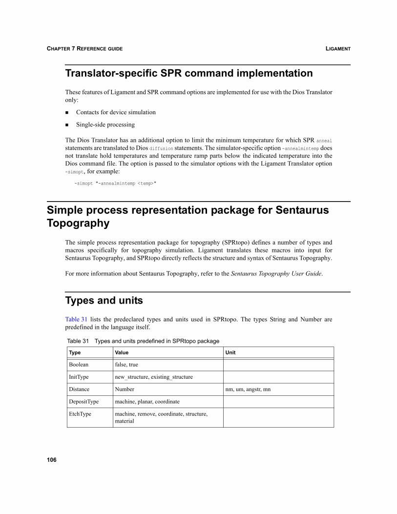
LIGAMENTCHAPTER 7 REFERENCE GUIDE
Translator-specific SPR command implementationThese features of Ligament and SPR command options are implemented for use with the Dios Translatoronly:
Contacts for device simulation
Single-side processing
The Dios Translator has an additional option to limit the minimum temperature for which SPR annealstatements are translated to Dios diffusion statements. The simulator-specific option -annealmintemp doesnot translate hold temperatures and temperature ramp parts below the indicated temperature into theDios command file. The option is passed to the simulator options with the Ligament Translator option-simopt, for example:
-simopt "-annealmintemp <temp>"
Simple process representation package for Sentaurus Topography
The simple process representation package for topography (SPRtopo) defines a number of types andmacros specifically for topography simulation. Ligament translates these macros into input forSentaurus Topography, and SPRtopo directly reflects the structure and syntax of Sentaurus Topography.
For more information about Sentaurus Topography, refer to the Sentaurus Topography User Guide.
Types and unitsTable 31 lists the predeclared types and units used in SPRtopo. The types String and Number arepredefined in the language itself.
Table 31 Types and units predefined in SPRtopo package
Type Value Unit
Boolean false, true
InitType new_structure, existing_structure
Distance Number nm, um, angstr, mn
DepositType machine, planar, coordinate
EtchType machine, remove, coordinate, structure, material
106
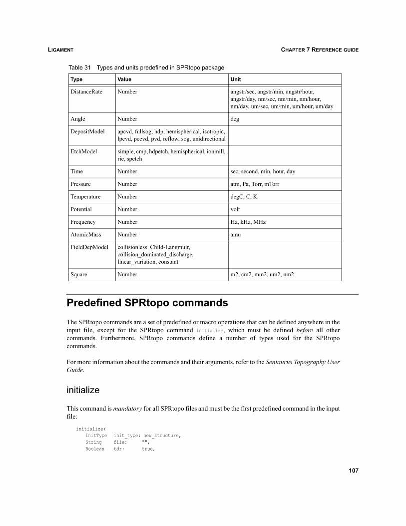
LIGAMENT CHAPTER 7 REFERENCE GUIDE
Predefined SPRtopo commandsThe SPRtopo commands are a set of predefined or macro operations that can be defined anywhere in theinput file, except for the SPRtopo command initialize, which must be defined before all othercommands. Furthermore, SPRtopo commands define a number of types used for the SPRtopocommands.
For more information about the commands and their arguments, refer to the Sentaurus Topography UserGuide.
initialize
This command is mandatory for all SPRtopo files and must be the first predefined command in the inputfile:
initialize(InitType init_type: new_structure,String file: "",Boolean tdr: true,
DistanceRate Number angstr/sec, angstr/min, angstr/hour,angstr/day, nm/sec, nm/min, nm/hour, nm/day, um/sec, um/min, um/hour, um/day
Angle Number deg
DepositModel apcvd, fullsog, hdp, hemispherical, isotropic, lpcvd, pecvd, pvd, reflow, sog, unidirectional
EtchModel simple, cmp, hdpetch, hemispherical, ionmill, rie, spetch
Time Number sec, second, min, hour, day
Pressure Number atm, Pa, Torr, mTorr
Temperature Number degC, C, K
Potential Number volt
Frequency Number Hz, kHz, MHz
AtomicMass Number amu
FieldDepModel collisionless_Child-Langmuir, collision_dominated_discharge, linear_variation, constant
Square Number m2, cm2, mm2, um2, nm2
Table 31 Types and units predefined in SPRtopo package
Type Value Unit
107
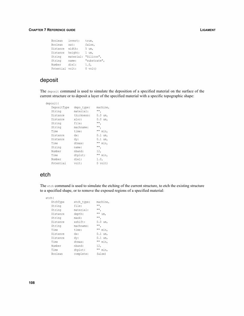
LIGAMENTCHAPTER 7 REFERENCE GUIDE
Boolean invert: true,Boolean sat: false,Distance width: 5 um,Distance height: 1 um,String material: "Silicon",String name: "substrate",Number diel: 1.0,Potential volt: 0 volt)
deposit
The deposit command is used to simulate the deposition of a specified material on the surface of thecurrent structure or to deposit a layer of the specified material with a specific topographic shape:
deposit(DepositType depo_type: machine,String material: "",Distance thickness: 0.0 um,Distance xloc: 0.0 um,String file: "",String machname: "",Time time: "" min,Distance dx: 0.1 um,Distance dy: 0.1 um,Time dtmax: "" min,String name: "",Number nband: 12,Time dtplot: "" min,Number diel: 1.0,Potential volt: 0 volt)
etch
The etch command is used to simulate the etching of the current structure, to etch the existing structureto a specified shape, or to remove the exposed regions of a specified material:
etch(EtchType etch_type: machine,String file: "",String material: "",Distance depth: "" um,String mask: "",Distance xshift: 0.0 um,String machname: "",Time time: "" min,Distance dx: 0.1 um,Distance dy: 0.1 um,Time dtmax: "" min,Number nband: 12,Time dtplot: "" min,Boolean complete: false)
108
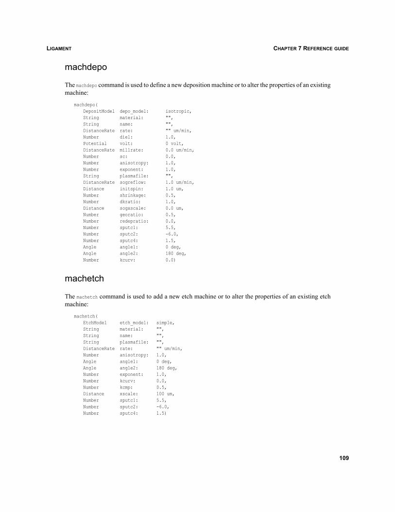
LIGAMENT CHAPTER 7 REFERENCE GUIDE
machdepo
The machdepo command is used to define a new deposition machine or to alter the properties of an existingmachine:
machdepo(DepositModel depo_model: isotropic,String material: "",String name: "",DistanceRate rate: "" um/min,Number diel: 1.0,Potential volt: 0 volt,DistanceRate millrate: 0.0 um/min,Number sc: 0.0,Number anisotropy: 1.0,Number exponent: 1.0,String plasmafile: "",DistanceRate sogreflow: 1.0 um/min,Distance initspin: 1.0 um,Number shrinkage: 0.5,Number dkratio: 1.0,Distance sogxscale: 0.0 um,Number georatio: 0.5,Number redepratio: 0.0,Number sputc1: 5.5,Number sputc2: -6.0,Number sputc4: 1.5,Angle angle1: 0 deg,Angle angle2: 180 deg,Number kcurv: 0.0)
machetch
The machetch command is used to add a new etch machine or to alter the properties of an existing etchmachine:
machetch(EtchModel etch_model: simple,String material: "",String name: "",String plasmafile: "",DistanceRate rate: "" um/min,Number anisotropy: 1.0,Angle angle1: 0 deg,Angle angle2: 180 deg,Number exponent: 1.0,Number kcurv: 0.0,Number kcmp: 0.5,Distance xscale: 100 um,Number sputc1: 5.5,Number sputc2: -6.0,Number sputc4: 1.5)
109
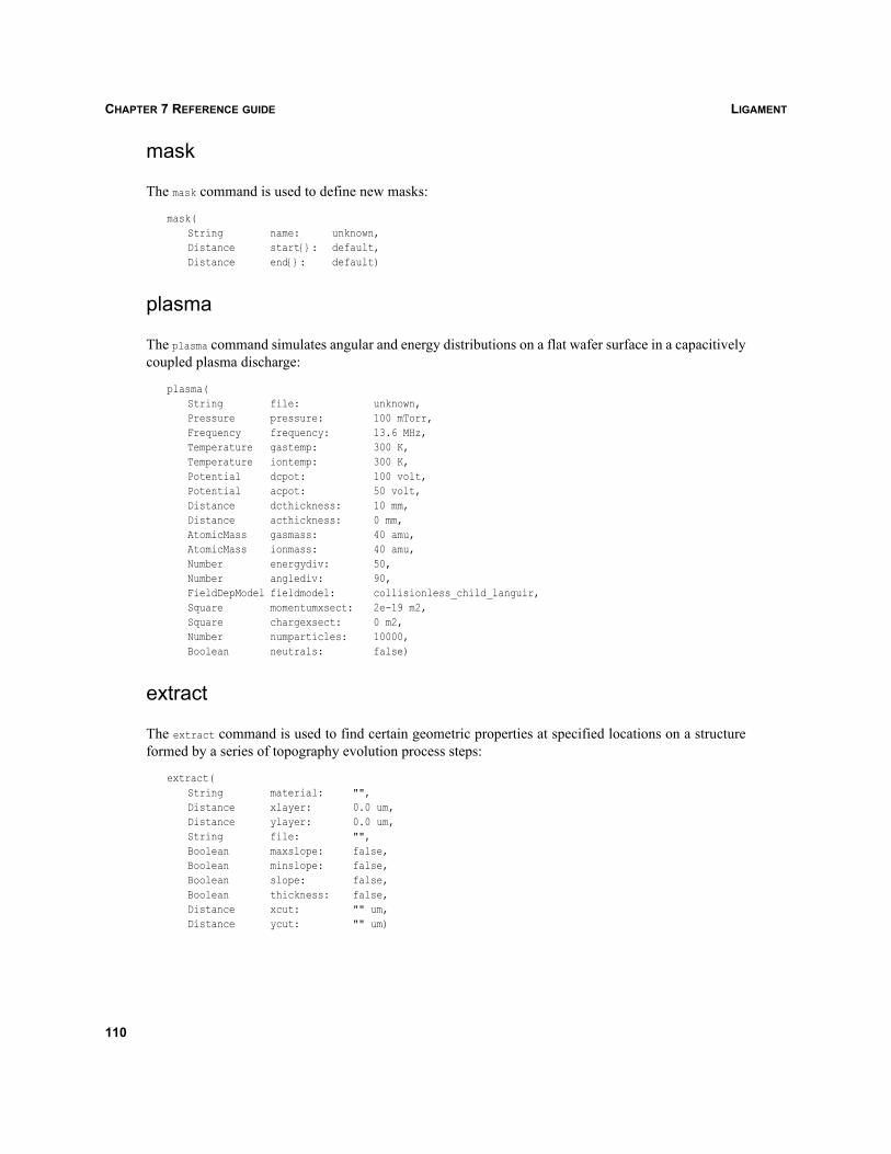
LIGAMENTCHAPTER 7 REFERENCE GUIDE
mask
The mask command is used to define new masks:
mask(String name: unknown,Distance start{}: default,Distance end{}: default)
plasma
The plasma command simulates angular and energy distributions on a flat wafer surface in a capacitivelycoupled plasma discharge:
plasma(String file: unknown,Pressure pressure: 100 mTorr,Frequency frequency: 13.6 MHz,Temperature gastemp: 300 K,Temperature iontemp: 300 K,Potential dcpot: 100 volt,Potential acpot: 50 volt,Distance dcthickness: 10 mm,Distance acthickness: 0 mm,AtomicMass gasmass: 40 amu,AtomicMass ionmass: 40 amu,Number energydiv: 50,Number anglediv: 90,FieldDepModel fieldmodel: collisionless_child_languir,Square momentumxsect: 2e-19 m2,Square chargexsect: 0 m2,Number numparticles: 10000,Boolean neutrals: false)
extract
The extract command is used to find certain geometric properties at specified locations on a structureformed by a series of topography evolution process steps:
extract(String material: "",Distance xlayer: 0.0 um,Distance ylayer: 0.0 um,String file: "",Boolean maxslope: false,Boolean minslope: false,Boolean slope: false,Boolean thickness: false,Distance xcut: "" um,Distance ycut: "" um)
110
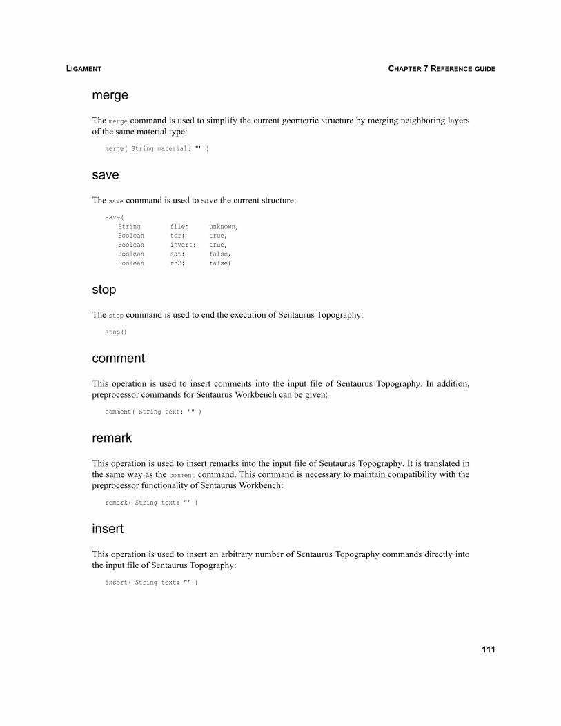
LIGAMENT CHAPTER 7 REFERENCE GUIDE
merge
The merge command is used to simplify the current geometric structure by merging neighboring layersof the same material type:
merge( String material: "" )
save
The save command is used to save the current structure:
save(String file: unknown,Boolean tdr: true,Boolean invert: true,Boolean sat: false,Boolean rc2: false)
stop
The stop command is used to end the execution of Sentaurus Topography:
stop()
comment
This operation is used to insert comments into the input file of Sentaurus Topography. In addition,preprocessor commands for Sentaurus Workbench can be given:
comment( String text: "" )
remark
This operation is used to insert remarks into the input file of Sentaurus Topography. It is translated inthe same way as the comment command. This command is necessary to maintain compatibility with thepreprocessor functionality of Sentaurus Workbench:
remark( String text: "" )
insert
This operation is used to insert an arbitrary number of Sentaurus Topography commands directly intothe input file of Sentaurus Topography:
insert( String text: "" )
111
LIGAMENTCHAPTER 7 REFERENCE GUIDE
‘material’ argument for Sentaurus Topography commandsThe following SPRtopo commands have a material argument:
initialize
deposit
etch
machdepo
machetch
extract
merge
When creating an SPRtopo process flow in Ligament Flow Editor, a list of DATEX materials is providedfrom which users can select the material.
‘mask’ argument for Sentaurus Topography commandsThe following SPRtopo command has a mask argument:
etch
When creating an SPRtopo process flow in Ligament Flow Editor, a list of predefined mask names isprovided from which users can select the mask. This list combines sets of mask names specified indifferent locations:
Mask names defined by the mask commands of Sentaurus Topography in the file mask.lib, which islocated in directories specified by the environment variable SPTOPO_LIBRARY_PATH.
Mask names defined by the mask commands of Sentaurus Topography in the local project filemask.lib.
Mask names defined in the corresponding layout file, created by Ligament Layout Editor. Thesenames have the format SIM2D_<name>.
Mask names specified by SPRtopo mask commands in the same Ligament process flow.
112
LIGAMENT CHAPTER 7 REFERENCE GUIDE
Machine names for Sentaurus Topography commandsThe following SPRtopo commands have a machname argument:
deposit
etch
When creating an SPRtopo process flow in Ligament Flow Editor, two lists of predefined machinenames are provided for the deposit and etch commands separately. These lists combine correspondingsets of machine names specified in different locations:
Machine names defined by the machdepo and machetch commands of Sentaurus Topography in thefiles machdepo.lib and machetch.lib, which are located in directories specified by the environmentvariable SPTOPO_LIBRARY_PATH.
Machine names defined by the machdepo and machetch commands of Sentaurus Topography in thelocal project files machdepo.lib and machetch.lib.
Machine names specified by the SPRtopo machdepo and machetch commands in the same Ligamentprocess flow.
113

LIGAMENTCHAPTER 7 REFERENCE GUIDE
114
LIGAMENT GLOSSARY
Ligament
Glossary
argumentConsists of an argument value and, in some cases, an argument unit.
argument unitPhysical unit of a macro argument.
argument valueValue of a macro argument.
conditional statementAllows the selection of different cases in a simulation flow, based on the value of a logical expression.
drawing areaDrawing area within the layout.
flowHierarchical representation of the process in which all macro calls and the contents of macros arevisible.
generic commandBuilt-in Ligament commands that are not directly related to process simulation.
global contactsContacts for device simulation that are automatically matched to the processed structure by the processsimulator.
graphical editingEditing the process flow and layout-related simulation options with interactive graphical userinterfaces.
grid sizeInterval of the coordinate grid, in the Ligament Layout Editor, to which drawing operations areconstrained.
import layoutImports layouts into the Ligament Layout Editor. See layout library.
layer listList of layers used in a particular layout. It is located on the left pane of the Ligament Layout Editor. Itallows users to select layers for drawing or modifying operations.
layout dimensionCoordinate range of the layout.
115
LIGAMENTGLOSSARY
layout libraryImported layout, not subject to editing by Ligament Layout Editor.
layout parameterizationAllows users to stretch a layout across lines in the layout with a Sentaurus Workbench parameter.
library macroA Ligament language macro whose definition is not contained in the currently edited flow, but in alibrary. The content of the macro is, therefore, determined at the time of translation of the flow usingLigament Translator.
library variableA Ligament language variable whose definition is not contained in the currently edited flow, but in alibrary. The content of the macro is, therefore, determined at the time of translation of the flow usingLigament Translator.
Ligament Flow EditorThis is a graphical input for Ligament. It is used to specify a process flow in a simulator-independentinput language.
Ligament Layout EditorIt allows users to draw or modify layouts, set simulation regions, and parameterize layouts with layoutparameters and layer operations, such as scaling, rotating, shifting, and rounding.
Ligament TranslatorTranslates process flow information and layout information into specific simulator input languages orother formats.
local contactsContacts for device simulation, the position of which is defined in the layout by rectangles or polygons.
local macroA Ligament language macro, the definition of which is contained in the currently edited flow.
macroA Ligament language macro can be defined by users and allows users to group a number of basicLigament commands or other macros for further use. Macros can take arguments.
merging layoutThe importing of an additional layout and adding it to an existing layout.
mode selectionThe selection between layout and TCAD modes in Ligament Layout Editor.
process commandLigament commands relating to a semiconductor manufacturing process step.
process flowA Ligament flow.
116
LIGAMENT GLOSSARY
reference layoutImporting an additional layout without merging it to the current layout. See layout library.
repositorySpecifies the place where a collection of macro files is stored in hierarchical directory structure. Itconsists of the path and a number of options for resolving macros.
Sentaurus TopographyA two-dimensional topography simulation tool, which performs analyses of IC fabrication, etch,deposition, and other geometric operations.
simple process representation (SPR)A set of commands of the Ligament language, which are useful for describing semiconductormanufacturing processing steps.
simulationModeling reality with computer assistance.
unfolded flowRepresentation of the simulation flow as a flat flow where all macros have been resolved and onlycommands predefined in the Ligament language remain.
variableGlobally defined variables can be used as macro arguments.
variable substitutionReplacement of an argument, whose value is or contains a variable, with its actual value.
workspaceIn Ligament, a collection of information that can be given in the command lines of Ligament tools.
117

LIGAMENTGLOSSARY
118