Life Safety Dampers - Greenheck · 1 Life Safety Dampers • Fire • Combination Fire Smoke •...
36
Life Safety Dampers • Fire • Combination Fire Smoke • Smoke • Ceiling Radiation April 2017
Transcript of Life Safety Dampers - Greenheck · 1 Life Safety Dampers • Fire • Combination Fire Smoke •...

1
Life Safety Dampers• Fire • Combination Fire Smoke• Smoke • Ceiling Radiation
April 2017

2
Life Safety Dampers
The Greenheck DifferenceWhat makes Greenheck different from other damper manufacturers? Perhaps it’s having the most UL Certified dampers or industry-leading testing capabilities. Most Greenheck dampers meet California State Fire Marshal and NY MEA requirements. Aggressive research and development also keeps Greenheck at the front of the damper industry.
Unparalleled In-House Testing CapabilitiesInternal testing capabilities are directly related to product quality and the ability to meet stringent code requirements. With industry-leading testing abilities, Greenheck can introduce new products faster, and can quickly develop qualified products for your unique applications. Our dampers qualify to UL 555, UL 555C, UL 555S and AMCA 500-D test standards.
Quick Build and Quick DeliveryGreenheck’s Quick Build (QB) program, along with strategic manufacturing locations, ensures rapid response time. Products are manufactured on a 1-, 3, 5-, 10- or 25-day program, then efficiently shipped to your jobsite.
Leading Edge Technical SupportAll Greenheck products are supported by the industry’s best product literature, electronic media, and Computer Aided Product Selection program (CAPS). You’ll also find extensive information on our website, www.greenheck.com.
You can always count on the personal service and expertise of our national and international representative organizations. To locate your nearest Greenheck representative, call 715-359-6171, or visit our website at www.greenheck.com
456935
COMBINATION FIRE/SMOKE DAMPERS
DFD, FSD, SSDFD, SSFSD,ODFD, OFSD, OSSDFD, OSSFSD
Greenheck Fan Corporation
#3230-0981:110NYC MEA #260-91-MComplies with UBC
CSFM Listing #3225-0981:103
#3225-0981:109#3230-0981:104
SERIES COMBINATIONFIRE/SMOKE DAMPERS
GREENHECK FANP/N 456935
JOB# 86767H:/WIP/LINDAWIP/420-6767
7/24/97
FIRE/SMOKE DAMPERSSERIES COMBINATION
#3230-0981:104#3225-0981:109
CSFM Listing #3225-0981:103
Complies with UBC NYC MEA #260-91-M
#3230-0981:110
Greenheck Fan Corporation
ODFD, OFSD, OSSDFD, OSSFSDDFD, FSD, SSDFD, SSFSD,
COMBINATION FIRE/SMOKE DAMPERS
456935
200%
Table of Contents Page(s)
Introduction to Life Safety Dampers . . . . . . . . . . . . . . . . . . . . . . . . . . 3Fire Dampers . . . . . . . . . . . . . . . . . . . . . . . . . . . . . . . . . . . . .4-11Combination Fire Smoke & Smoke Dampers . . . . . . . . . . . . . . . . . . . 12-18Round UL Dampers . . . . . . . . . . . . . . . . . . . . . . . . . . . . . . . . . 19-20Ceiling Radiation Dampers . . . . . . . . . . . . . . . . . . . . . . . . . . . . . 21-22Installation & Convenience Features . . . . . . . . . . . . . . . . . . . . . . . . 23-24Options & Accessories . . . . . . . . . . . . . . . . . . . . . . . . . . . . . . . 24-26Factory-Mounted Accessories . . . . . . . . . . . . . . . . . . . . . . . . . . . . . 27Pressure Drop Data . . . . . . . . . . . . . . . . . . . . . . . . . . . . . . . . . 28-31Model Definition . . . . . . . . . . . . . . . . . . . . . . . . . . . . . . . . . . . . . 32Drive Arrangement Definition . . . . . . . . . . . . . . . . . . . . . . . . . . . . . . 33Listings/Approvals . . . . . . . . . . . . . . . . . . . . . . . . . . . . . . . . . . . 33Test Standards & Certifications . . . . . . . . . . . . . . . . . . . . . . . . . . . . . 34Specification Checklist . . . . . . . . . . . . . . . . . . . . . . . . . . . . . . . . . 35Horizontal Non-Concrete Openings . . . . . . . . . . . . . . . . . . . . . Backcover
3
Life Safety Dampers
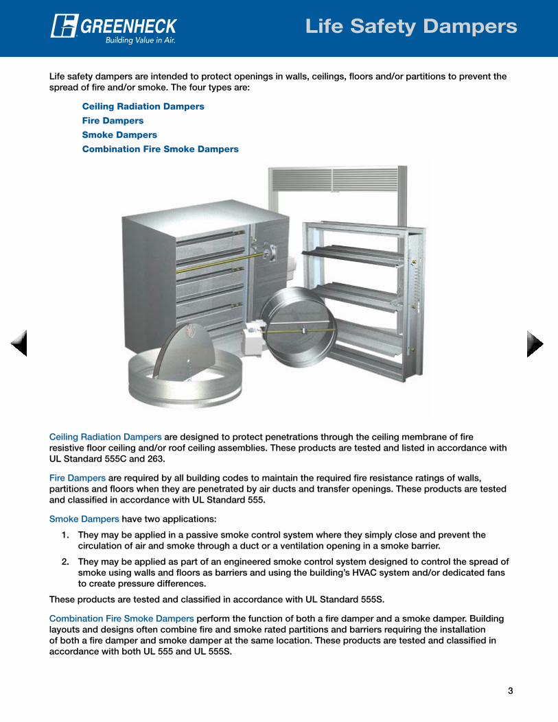
Life safety dampers are intended to protect openings in walls, ceilings, floors and/or partitions to prevent the spread of fire and/or smoke. The four types are:
Ceiling Radiation Dampers
Fire Dampers
Smoke Dampers
Combination Fire Smoke Dampers
Ceiling Radiation Dampers are designed to protect penetrations through the ceiling membrane of fire resistive floor ceiling and/or roof ceiling assemblies. These products are tested and listed in accordance with UL Standard 555C and 263.
Fire Dampers are required by all building codes to maintain the required fire resistance ratings of walls, partitions and floors when they are penetrated by air ducts and transfer openings. These products are tested and classified in accordance with UL Standard 555.
Smoke Dampers have two applications:
1. They may be applied in a passive smoke control system where they simply close and prevent the circulation of air and smoke through a duct or a ventilation opening in a smoke barrier.
2. They may be applied as part of an engineered smoke control system designed to control the spread of smoke using walls and floors as barriers and using the building’s HVAC system and/or dedicated fans to create pressure differences.
These products are tested and classified in accordance with UL Standard 555S.
Combination Fire Smoke Dampers perform the function of both a fire damper and a smoke damper. Building layouts and designs often combine fire and smoke rated partitions and barriers requiring the installation of both a fire damper and smoke damper at the same location. These products are tested and classified in accordance with both UL 555 and UL 555S.
4
Fire Dampers
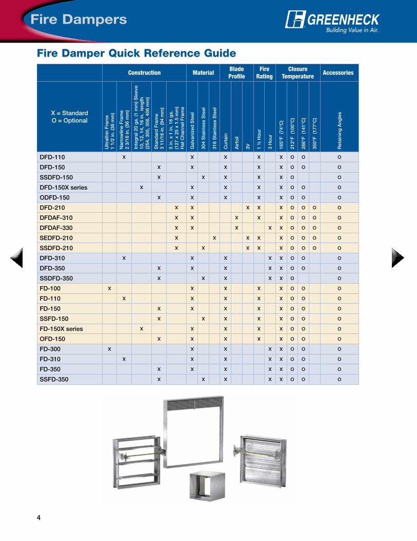
Fire Damper Quick Reference Guide
Accessories
Ret
aini
ng A
ngle
s
O
O
O
O
O
O
O
O
O
O
O
O
O
O
O
O
O
O
O
O
O
O
O
Closure Temperature
350°
F (
177°
C)
O
O
O
O
O
286°
F (
141°
C)
O
O
O
O
O
O
O
O
O
O
O
O
O
O
O
O
O
O
O
O
O
212°
F (
100°
C)
O
O
O
O
O
O
O
O
O
O
O
O
O
O
O
O
O
O
O
O
O
O
O
165°
F (
74°C
)
X
X
X
X
X
X
X
X
X
X
X
X
X
X
X
X
X
X
X
X
X
X
X
Fire Rating
3 H
our
X
X
X
X
X
X
X
X
1 ½
Ho
ur
X
X
X
X
X
X
X
X
X
X
X
X
X
X
X
Blade Profile
3V
X
X
X
Air
foil
X
X
Cur
tain
X
X
X
X
X
X
X
X
X
X
X
X
X
X
X
X
X
X
Material
316
Sta
inle
ss S
teel
X
304
Sta
inle
ss S
teel
X
X
X
X
X
Gal
vani
zed
Ste
el
X
X
X
X
X
X
X
X
X
X
X
X
X
X
X
X
X
Construction
5 in
. x 1
in. 1
6 g
a.(1
27 x
25
x 1.
5 m
m)
Hat
Cha
nnel
Fra
me
X
X
X
X
X
Sta
ndar
d F
ram
e 3
11/1
6 in
. (94
mm
)
X
X
X
X
X
X
X
X
X
X
Inte
gra
l 20
ga.
(1 m
m) S
leev
e
10, 1
2, 1
4, 1
6 in
. le
ngth
(254
, 305
, 356
, 406
mm
)
X
X
Nar
row
line
Fra
me
2 3/
16 in
. (56
mm
)
X
X
X
X
Ultr
athi
n F
ram
e1
1/2
in. (
38 m
m)
X
X
X = StandardO = Optional
DFD-110
DFD-150
SSDFD-150
DFD-150X series
ODFD-150
DFD-210
DFDAF-310
DFDAF-330
SEDFD-210
SSDFD-210
DFD-310
DFD-350
SSDFD-350
FD-100
FD-110
FD-150
SSFD-150
FD-150X series
OFD-150
FD-300
FD-310
FD-350
SSFD-350

5
Fire Dampers
Fire Rated Partition
Factory Supplied Thermal Blanket
Fire Damper
Grille(supplied by others)
7-1/2 inch
maximum
Stainless SteelClosure Spring
‘K’ Side
Fusible Link (replaceable)165°F. standard (212°F. available)
HORIZONTAL MOUNT
VERTICAL MOUNT3-11/16 inch
H*
W*
MountingFire dampers are available for mounting either vertically or horizontally (below left and center). Greenheck also offers fire dampers for out-of-the-wall installation (right).
Close Indicator SwitchThe close indicator switch sends a signal when the damper blades are closed.
Factory Sleeve OptionFire dampers are available in factory-furnished sleeves. Sleeves are galvanized steel or stainless steel, depending on the model, and are available in 10 through 20 ga. (3 through 1 mm) thicknesses and lengths up to 48 in. (1219 mm).
The “K” dimension specifies the location of the damper within the sleeve. Horizontal dampers must be installed with the “K” dimension on the top (K-side facing up).
Integral Sleeve (X series)X series dampers in the FD and DFD model lines have the sleeve formed with the fire damper frame as one piece providing the most economical solution for sleeved fire dampers. The frame with integral sleeve is constructed of galvanized steel.
TransitionsWhen a rectangular fire damper is being used in conjunction with round, square or oval ductwork, they can be supplied in a factory sleeve with round, square or oval transitions on one or both ends of the sleeve. Dampers should be ordered to the duct dimensions. For medium pressure ductwork, Greenheck can seal the transition and sleeve seams to prevent air leakage.
Type A Type B/B2 Type C
Type CO Type CR Type R
Type A Type B/B2 Type C
Type CO Type CR Type R
H*
KDamper Location W*
CL Damper Fram
Sleeve
CL Damper Frame
Damper
Overall Sleeve Length
12 in. = DFD-150X1210 in. = DFD-150X10
14 in. = DFD-150X1416 in. = DFD-150X16
Fusible Link (replaceable)165°F. standard (212°F. available)
OFD/ODFD Series
Design and Construction Features
* These dimensions are furnished approximately 1/4 in. (6 mm) undersize. (Add sleeve thickness for overall sleeved damper dimension)
6
Fire Dampers
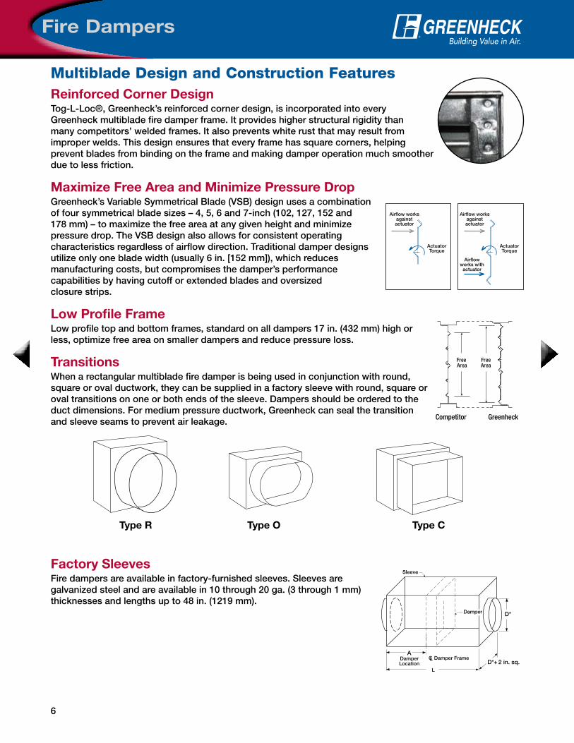
Reinforced Corner DesignTog-L-Loc®, Greenheck’s reinforced corner design, is incorporated into every Greenheck multiblade fire damper frame. It provides higher structural rigidity than many competitors’ welded frames. It also prevents white rust that may result from improper welds. This design ensures that every frame has square corners, helping prevent blades from binding on the frame and making damper operation much smoother due to less friction.
Maximize Free Area and Minimize Pressure DropGreenheck’s Variable Symmetrical Blade (VSB) design uses a combination of four symmetrical blade sizes – 4, 5, 6 and 7-inch (102, 127, 152 and 178 mm) – to maximize the free area at any given height and minimize pressure drop. The VSB design also allows for consistent operating characteristics regardless of airflow direction. Traditional damper designs utilize only one blade width (usually 6 in. [152 mm]), which reduces manufacturing costs, but compromises the damper’s performance capabilities by having cutoff or extended blades and oversized closure strips.
Low Profile FrameLow profile top and bottom frames, standard on all dampers 17 in. (432 mm) high or less, optimize free area on smaller dampers and reduce pressure loss.
TransitionsWhen a rectangular multiblade fire damper is being used in conjunction with round, square or oval ductwork, they can be supplied in a factory sleeve with round, square or oval transitions on one or both ends of the sleeve. Dampers should be ordered to the duct dimensions. For medium pressure ductwork, Greenheck can seal the transition and sleeve seams to prevent air leakage.
Factory SleevesFire dampers are available in factory-furnished sleeves. Sleeves are galvanized steel and are available in 10 through 20 ga. (3 through 1 mm) thicknesses and lengths up to 48 in. (1219 mm).
ActuatorTorque
ActuatorTorque
Airflow worksagainstactuator
Airflow worksagainstactuator
Airflowworks with
actuator
Unbalanced BladeRequires Higher Torque
Balanced Blade Requires Less Torque
Free AreaMaximum Reduced
Greenheckwith VSB with 6 in. blades
with 7 in. blades
unbalancedblade
FreeArea
FreeArea
Competitor Greenheck
Type R Type O Type C
ADamperLocation
L
CL Damper Frame
Sleeve
Damper D*
D* + 2 in. sq.
Multiblade Design and Construction Features
7
Fire Dampers
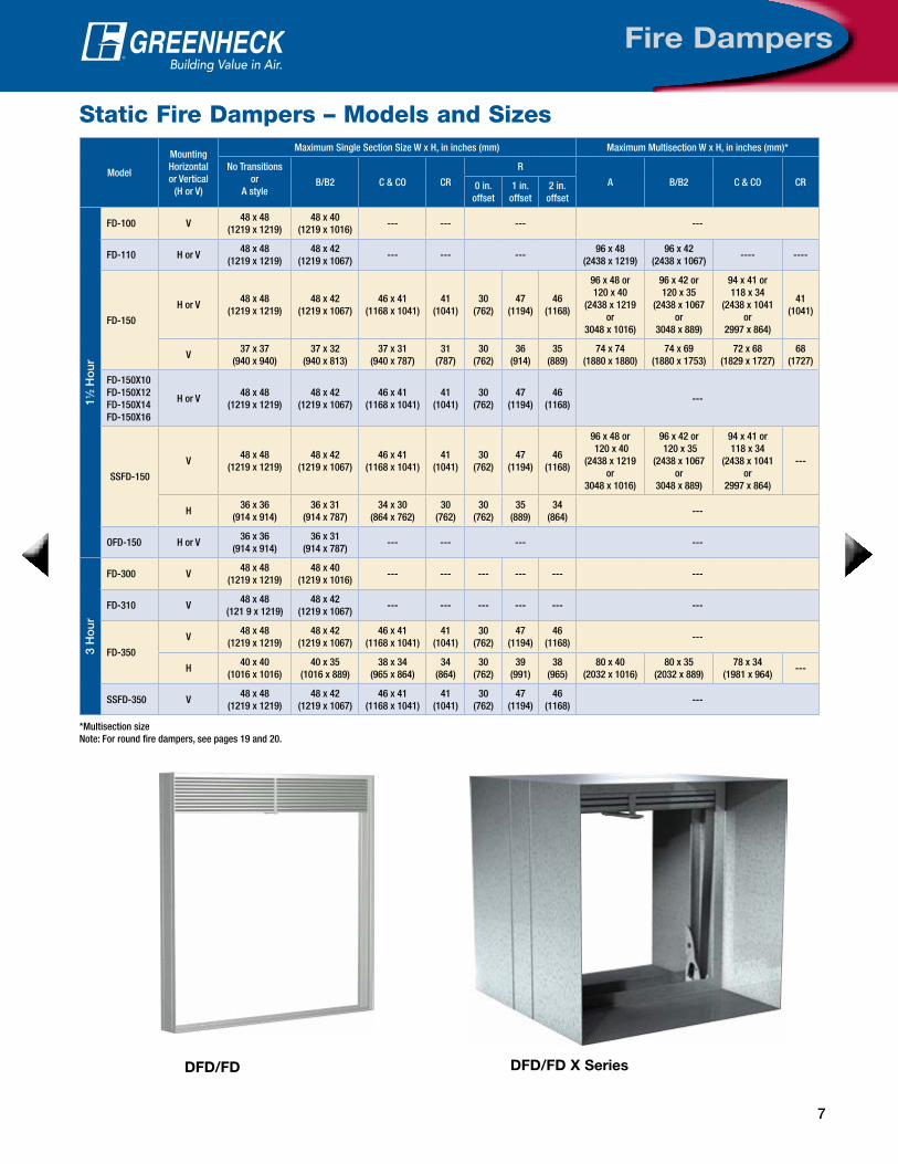
Static Fire Dampers – Models and Sizes
Model
Mounting Horizontal or Vertical
(H or V)
Maximum Single Section Size W x H, in inches (mm) Maximum Multisection W x H, in inches (mm)*
No Transitionsor
A styleB/B2 C & CO CR
R
A B/B2 C & CO CR0 in. offset
1 in. offset
2 in. offset
11 ⁄2 H
our
FD-100 V48 x 48
(1219 x 1219)48 x 40
(1219 x 1016)--- --- --- ---
FD-110 H or V48 x 48
(1219 x 1219)48 x 42
(1219 x 1067)--- --- ---
96 x 48(2438 x 1219)
96 x 42(2438 x 1067)
---- ----
FD-150
H or V48 x 48
(1219 x 1219)48 x 42
(1219 x 1067)46 x 41
(1168 x 1041)41
(1041)30
(762)47
(1194)46
(1168)
96 x 48 or 120 x 40
(2438 x 1219 or
3048 x 1016)
96 x 42 or120 x 35
(2438 x 1067 or
3048 x 889)
94 x 41 or 118 x 34
(2438 x 1041 or
2997 x 864)
41(1041)
V37 x 37
(940 x 940)37 x 32
(940 x 813)37 x 31
(940 x 787)31
(787)30
(762)36
(914)35
(889)74 x 74
(1880 x 1880)74 x 69
(1880 x 1753)72 x 68
(1829 x 1727)68
(1727)
FD-150X10FD-150X12FD-150X14FD-150X16
H or V48 x 48
(1219 x 1219)48 x 42
(1219 x 1067)46 x 41
(1168 x 1041)41
(1041)30
(762)47
(1194)46
(1168)---
SSFD-150
V48 x 48
(1219 x 1219)48 x 42
(1219 x 1067)46 x 41
(1168 x 1041)41
(1041)30
(762)47
(1194)46
(1168)
96 x 48 or 120 x 40
(2438 x 1219 or
3048 x 1016)
96 x 42 or 120 x 35
(2438 x 1067or
3048 x 889)
94 x 41 or 118 x 34
(2438 x 1041 or
2997 x 864)
---
H36 x 36
(914 x 914)36 x 31
(914 x 787)34 x 30
(864 x 762)30
(762)30
(762)35
(889)34
(864)---
OFD-150 H or V36 x 36
(914 x 914)36 x 31
(914 x 787)--- --- --- ---
3 H
our
FD-300 V48 x 48
(1219 x 1219)48 x 40
(1219 x 1016)--- --- --- --- --- ---
FD-310 V48 x 48
(121 9 x 1219)48 x 42
(1219 x 1067)--- --- --- --- --- ---
FD-350
V48 x 48
(1219 x 1219)48 x 42
(1219 x 1067)46 x 41
(1168 x 1041)41
(1041)30
(762)47
(1194)46
(1168)---
H40 x 40
(1016 x 1016)40 x 35
(1016 x 889)38 x 34
(965 x 864)34
(864)30
(762)39
(991)38
(965)80 x 40
(2032 x 1016)80 x 35
(2032 x 889)78 x 34
(1981 x 964)---
SSFD-350 V48 x 48
(1219 x 1219)48 x 42
(1219 x 1067)46 x 41
(1168 x 1041)41
(1041)30
(762)47
(1194)46
(1168)---
*Multisection sizeNote: For round fire dampers, see pages 19 and 20.
DFD/FD DFD/FD X Series

8
Fire Dampers
Model
MountingHorizontal or Vertical
(H or V)
Maximum Maximum Size W x H, in inches (mm)
Temperature°F/°C
Velocityft/min. (m/s)
Pressurein. wg (kPa)
No Transitions or A style
B/B2 C & CO CR
R
SingleSection
Multisection0 in.
offset1 in.
offset2 in.
offset
DFD-110
V
165°/74°
2000(10)
4(1)
36 x 36(914 x 914)
72 x 48 (1829 x 1219)
72 x 45(1829 x 1143)
--- --- ---
3000(15.2)
30 x 30(762 x 762)
---30 x 26
(762 x 660)
4000(20)
24 x 24 or18 x 30
(610 x 610 or457 x 762)
---
24 x 21 or18 x 26
(610 x 533 or 457 x 660)
H2000(10)
30 x 30(762 x 762)
48 x 36 (1219 x 914)
48 x 33(1219 x 838)
V
212°/100°
2000(10)
24 x 24(610 x 610)
48 x 36 or18 x 48
(1219 x 914 or 457 x 1219)
48 x 31 or18 x 45
(1219 x 787 or 457 x 1143)
3000 or 4000(15.2 or 20)
18 x 30(457 x 762)
---18 x 26
(457 x 660)
H2000(10)
24 x 24(610 x 610)
48 x 36 (1219 x 914)
48 x 33(1219 x 838)
V
286°/141°
2000(10)
24 x 24(610 x 610)
18 x 48 (457 x 1219)
18 x 45(457 x 1143)
3000 or 4000(15.2 or 20)
18 x 30(457 x 762)
---18 x 26
(457 x 660)
H2000(10)
24 x 24(610 x 610)
---24 x 21
(610 x 533)
DFD-150
V
165°/74°
2000(10)
4(1)
36 x 36(914 x 914)
72 x 48, 60 x 60 or 120 x 30
(1829 x 1219, 1524 x 1524 or
3048 x 762)
72 x 45, 60 x 58 or 120 x 26
(1829 x 1143, 1524 x 1422 or
3048 x 660)
70 x 44, 58 x 55or 118 x 25
(1778 x 1118, 1473 x 1397 or
2997 x 635)
55(1397)
30(762)
59(1499)
58(1473)
3000(15.2)
30 x 30(762 x 762)
---30 x 26
(762 x 660)28 x 25
(711 x 635)25
(635)30
(762)29
(737)28
(711)
4000(20)
24 x 24 or18 x 30
(610 x 610 or457 x 762)
---
24 x 21 or18 x 26
(610 x 533 or457 x 660)
22 x 20 or16 x 25
(559 x 508 or 406 x 635)
20(508)
24(610)
23(584)
22(559)
H2000(10)
30 x 30(762 x 762)
48 x 36(1219 x 914)
48 x 33(1219 x 838)
46 x 32(1168 x 813)
32(813)
30(762)
35(889)
34(864)
V
212°/100°
2000(10)
24 x 24 or18 x 30
(610 x 610 or457 x 762)
48 x 36 or18 x 60
(1219 x 914457 x 1524)
48 x 31 or 18 x 56
(1219 x 787 or457 x 1422)
46 x 30 or16 x 55
(1168 x 762 or 406 x 1397)
30(762)
30(762)
35(889)
34(864)
3000 or 4000(15.2 or 20)
18 x 30(457 x 762)
---18 x 26
(457 x 660)16 x 25
(406 x 635)16
(406)18
(457)17
(432)16
(406)
H2000(10)
24 x 24(610 x 610)
48 x 36(1219 x 914)
48 x 33(1219 x 838)
46 x 32(1168 x 813)
32(813)
30(762)
35(889)
34(864)
V
286°/141°
2000(10)
24 x 24 or18 x 30
(610 x 610 or457 x 762)
18 x 60(457 x 1524)
24 x 21 or 18 x 56
(610 x 533 or 457 x 1422)
22 x 20 or 16 x 55
(559 x 508 or406 x 1397)
20(508)
24(610)
23(584)
22(559)
3000 or 4000(15.2 or 20)
18 x 30(457 x 762)
---18 x 26
(457 x 660)16 x 25
(406 x 635)16
(406)18
(457)17
(432)16
(406)
H2000(10)
24 x 24(610 x 610)
---24 x 21
(610 x 533)22 x 20
(559 x 508)20
(508)24
(610)23
(584)22
(559)
Dynamic Fire Dampers (11/2 Hour) – Models and Sizes
Note: For round fire dampers, see pages 19 and 20.

9
Fire Dampers
Model
MountingHorizontal or Vertical
(H or V)
Maximum Maximum Size W x H, in inches (mm)
Temperature°F/°C
Velocityft/min. (m/s)
Pressurein. wg (kPa)
No Transitions or A style
B/B2 C & CO CR
R
SingleSection
Multisection0 in.
offset1 in.
offset2 in.
offset
DFD-150X10DFD-150X12DFD-150X14DFD-150X16
V
165°/74°
2000(10)
4(1)
36 x 36(914 x 914)
---36 x 31
(914 x 787)34 x 30
(864 x 762)30
(762)30
(762)35
(889)34
(864)
3000(15.2)
30 x 30(762 x 762)
---30 x 26
(762 x 660)28 x 25
(762 x 635)25
(635)30
(762)29
(737)28
(711)
4000(20)
24 x 24(610 x 610)
---
24 x 21 or18 x 26
(610 x 533 or 457 x 660)
22 x 20 or16 x 25
(559 x 508 or406 x 635)
22(559)
24(610)
23(584)
22(559)
H2000(10)
30 x 30(762 x 762)
---30 x 26
(762 x 660)28 x 25
(711 x 635)25
(635)30
(762)29
(737)28
(711)
V
212°/100°
2000(10)
24 x 24(610 x 610)
---
24 x 21 or18 x 26
(610 x 533 or 457 x 660)
22 x 20 or16 x 25
(559 x 508 or406 x 635)
22(559)
24(610)
23(584)
22(559)
3000 or 4000(15.2 or 20)
18 x 30(457 x 762)
---18 x 26
(457 x 660)16 x 25
(406 x 635)16
(406)18
(457)17
(432)16
(406)
H2000(10)
24 x 24(610 x 610)
---24 x 21
(610 x 533)22 x 20
(559 x 508)22
(559)24
(610)23
(584)22
(559)
V
286°/141°
2000(10)
24 x 24(610 x 610)
---
24 x 21 or18 x 26
(610 x 533 or 457 x 660)
22 x 20 or16 x 25
(559 x 508 or406 x 635)
22(559)
24 (610)
23(584)
22(559)
3000 or 4000(15.2 or 20)
18 x 30(457 x 762)
---18 x 26
(457 x 660)16 x 25
(406 x 635)16
(406)18
(457)17
(432)16
(406)
H2000(10)
24 x 24(610 x 610)
---24 x 21
(610 x 533)22 x 20
(559 x 508)22
(559)24
(610)23
(584)22
(559)
ODFD-150
V
165°/74°
2000(10)
4(1)
36 x 36(914 x 914)
---36 x 31
(914 x 787)---
3000(15.2)
30 x 30(762 x 762)
---30 x 26
(762 x 660)---
4000(20)
24 x 24 or18 x 30
(610 x 610 or457 x 762)
---
24 x 21 or18 x 26
(610 x 533 or(457 x 660)
---
H2000(10)
30 x 30(762 x 762)
36 x 36(914 x 914)
36 x 31(914 x 787)
---
V
212°/100°
2000(10)
24 x 24 or18 x 30
(610 x 610 or457 x 762)
36 x 36(914 x 914)
36 x 31(914 x 787)
---
3000 or 4000(15.2 or 20)
18 x 30(457 x 762)
---18 x 26
(457 x 660)---
H2000(10)
24 x 24(610 x 610)
36 x 36(914 x 914)
36 x 31(914 x 787)
---
V
286°/141°
2000(10)
24 x 24 or18 x 30
(610 x 610 or457 x 762)
36 x 36(914 x 914)
36 x 31(914 x 787)
---
3000 or 4000(15.2 or 20)
18 x 30(457 x 762)
---18 x 26
(457 x 660)---
H2000(10)
24 x 24(610 x 610)
---24 x 21
(610 x 533)---
SSDFD-150 V
Up to 212°/100° 2000
(10)4
(1)
30 x 30 (762 x 762)
---30 x 26
(762 x 660)28 x 25
(711 x 635)25
(635)30
(762)29
(737)28
(711)
286°/141°24 x 24
(610 x 610)---
24 x 21(610 x 533)
22 x 20(559 x 508)
20(508)
24(610)
23(584)
22(559)
Dynamic Fire Dampers (11/2 Hour) – Models and Sizes
Note: For round fire dampers, see pages 19 and 20.

10
Fire Dampers
Model
MountingHorizontalor Vertical
(H or V)
Maximum Maximum Size W x H, in inches (mm)
Temperature°F/°C
Velocityft/min. (m/s)
Pressurein. wg(kPa)
No Transitions or A style
B/B2 C & CO CR
R
Single Section
Multisection0 in.
offset1 in.
offset2 in.
offset
DFD-310
V
165°/74°
2000(10)
4(1)
36 x 36(914 x 914)
48 x 48(1219 x 1219)
48 x 45(1219 x 1143)
--- --- ---
3000(15.2)
4(1)
30 x 30(762 x 762)
---30 x 26
(762 x 660)
4000(20)
4(1)
24 x 24 or 18 x 30
(610 x 610 or457 x 762)
---
24 x 21 or18 x 26
(610 x 533 or457 x 660)
H2000(10)
4(1)
30 x 30(762 x 762)
40 x 36(1016 x 914)
40 x 33(1016 x 838)
V
212°/100°
2000(10)
4(1)
24 x 24(610 x 610)
48 x 36 or18 x 48
(1219 x 914 or 457 x 1219)
48 x 31 or18 x 45
(1219 x 787 or457 x 1143)
3000 or 4000 (15.2 or 20)
4(1)
18 x 30(457 x 762)
---18 x 26
(457 x 660)
H2000(10)
4(1)
24 x 24 or 18 x 30
(610 x 610 or457 x 762)
40 x 36(1016 x 914)
40 x 33(1016 x 838)
V
286°/141°
2000(10)
4(1)
24 x 24(610 x 610)
18 x 48(457 x 12190
18 x 45(457 x 1143)
3000 or 4000 (15.2 or 20)
4(1)
18 x 30(457 x 762)
---18 x 26
(457 x 660)
H2000(10)
4(1)
24 x 24(610 x 610)
---
24 x 21 or18 x 26
(610 x 533 or457 x 660)
DFD-350
V
165°/74°
2000(10)
4(1)
36 x 36(914 x 914)
48 x 48(1219 x 1219)
48 x 45(1219 x 1143)
46 x 44(1168 x 1118)
44(1118)
30(762)
47(1194)
46(1168)
3000(15.2)
4(1)
30 x 30(762 x 762)
---30 x 26
(762 x 660)28 x 25
(711 x 635)25
(635)30
(762)29
(737)28
(711)
4000(20)
4(1)
24 x 24 or 18 x 30
(610 x 610 or 457 x 762)
---
24 x 21 or18 x 26
(610 x 533 or 457 x 660)
22 x 20 or 16 x 25
(559 x 508 or 406 x 635)
20 (508)
24(610)
23(584)
22(559)
H2000(10)
4(1)
30 x 30(762 x 762)
40 x 36(1016 x 914)
40 x 33(1016 x 914)
38 x 32(965 x 813)
32(813)
30(762)
35(889)
34(864)
V
212°/100°
2000(10)
4(1)
24 x 24(610 x 610)
48 x 36 or 18 x 48
(1219 x 914 or457 x 1219)
48 x 31 or18 x 45
(1219 x 787 or 457 x 1143)
46 x 30 or16 x 44
(1168 x 762 or406 x 1118)
30(762)
30(762)
35(889)
34(864)
3000 or 4000(15.2 or 20)
4(1)
18 x 30(457 x 762)
---18 x 26
(457 x 660)16 x 25
(406 x 635)16
(406)18
(457)17
(432)16
(406)
H2000(10)
4(1)
30 x 30(762 x 762)
40 x 36(1016 x 914)
40 x 33(1016 x 914)
38 x 32(965 x 813)
32(813)
30(762)
35(889)
34(864)
V
286°/141°
2000(10)
4(1)
24 x 24(610 x 610)
18 x 48(457 x 1219)
24 x 21 or18 x 45
(610 x 533 or457 x 1143)
22 x 20 or16 x 44
(559 x 508 or406 x 1118)
20(508)
24(610)
23(584)
22(559)
3000 or 4000(15.2 or 20)
4(1)
18 x 30(457 x 762)
---18 x 26
(457 x 660)16 x 25
(406 x 635)16
(406)18
(457)17
(432)16
(406)
H2000(10)
4(1)
24 x 24(610 x 610)
---24 x 21
(610 x 533)22 x 20
(559 x 508)20
(508)24
(610)23
(584)22
(559)
SSDFD-350 V
up to 212°/100° 2000
(10)4
(1)
30 x 30(762 x 762)
---30 x 26
(762 x 660)28 x 25
(711 x 635)25
(635)30
(762)29
(737)28
(711)
286°/141°24 x 24
(610 x 610)---
24 x 21(610 x 533)
22 x 20(559 x 508)
20(508)
24(610)
23(584)
22(559)
Dynamic Fire Dampers (3 Hour) – Models and Sizes
Note: For round fire dampers, see pages 19 and 20.

11
Fire Dampers
Multiblade Dynamic Fire Dampers – Models and Sizes
Model
Mounting Horizontalor Vertical
(H or V)
Maximum Maximum Sizes H or V Installation, in inches (mm)
Temperature°F/°C
Velocityft/min. (m/s)
Pressurein. wg (kPa)
No Transitions
C & O
R
Single Section Size Multisection0 in.
offset1 in.
offset2 in.
offset
1½ H
our
DFD-210
H
Up to286°/141°
2000(10)
4(1)
32 x 50 (813 x 1270)
128 x 96(3251 x 2438)
C: 92 x 82(2337 x 2083)
O: 92 x 80(2337 x 2032)
30(762)
83(2108)
82(2083)
Up to 350°/177°
36 x 36(914 x 914)
---34 x 34
(864 x 864)30
(762)35
(889)34
(864)
V
Up to286°/141°
32 x 50 (813 x 1270)
128 x 100(3251 x 2540)
C: 92 x 82(2337 x 2083)
O: 92 x 80(2337 x 2032)
30(762)
83(2108)
82(2083)
Up to 350°/177°
36 x 36(914 x 914)
---34 x 34
(864 x 864)30
(762)35
(889)34
(864)
H or V
Up to 212°/100° 10
(2.5)
32 x 50(813 x 1270)
64 x 50 (1626 x 1270)
62 x 48 (1575 x 1219)
30(762)
49(1245)
48(1219)
Up to 350°/177°
36 x 36(914 x 914)
---34 x 34
(864 x 864)30
(762)35
(889)34
(864)
Up to 212°/100°
4000(20)
10(2.5)
32 x 50(813 x 1270)
---30 x 48
(762 x 1219)30
(762)31
(787)30
(762)
SEDFD-210 H or VUp to
350°/177°2000(10)
4(1)
24 x 30(610 x 762)
48 x 30(1219 x 762)
46 x 28(1168 x 711)
30 (762)
29(737)
28(711)
DFDAF-310
HUp to
350°/177°
2000(10)
4(1)
32 x 50(813 x 1219)
144 x 96(3658 x 2438)
C: 92 x 82(2337 x 2083)
O: 92 x 80(2337 x 2032)
30 (762)
83 (2108)
82(2083)
V
Up to286°/141°
32 x 50(813 x 1219)
128 x 100(3251 x 2540)
C: 92 x 82(2337 x 2083)
O: 92 x 80(2337 x 2032)
30 (762)
83(2108)
82(2083)
Up to 350°/177°
32 x 50(813 x 1219)
96 x 50(2438 x 1219)
92 x 48(2337 x 1219)
30 (762)
49(1245)
48(1219)
H or VUp to
350°/177°4000(20)
8(2)
32 x 50(813 x 1219)
---30 x 48
(762 x 1219)30
(762)31
(787)30
(762)
3 H
our
DFDAF-330
V
Up to286°/141°
2000(10)
4(1)
32 x 36 or 30 x 48(813 x 914 or 762 x 1219)
120 x 96(3048 x 2438)
C: 92 x 82(2337 x 2083)
O: 92 x 80(2337 x 2032)
30 (762)
83 (2108)
82(2083)
Up to 350°/177°
32 x 36 or 30 x 48(813 x 914 or 762 x 1219)
32 x 48(813 x 1219)
30 x 46(762 x 1219)
30(762)
31(787)
30(762)
H
Up to286°/141°
30 x 48(762 x 1219)
144 x 96(3658 x 2438)
C: 92 x 82(2337 x 2083)
O: 92 x 80(2337 x 2032)
30 (762)
83(2108)
82(2083)
Up to 350°/177°
30 x 48(762 x 1219)
32 x 48 (813 x 1219)
30 x 46 (762 x 1168)
30 (762)
31 (787)
30 (762)
H or VUp to
350°/177°4000 (20)
8 (2)
30 x 48 (762 x 1219)
--28 x 46
(711 x 1168)30
(762)29
(737)28
(711)
Note: For round fire dampers, see pages 19 and 20.

12
Combination Fire Smoke& Smoke Dampers
Quick Reference Guide
X = StandardO = Optional
FrameBlade Profile
Leakage Class
FireRating
ClosureTemperature
Closure Device
Accessories
5 x
1 in
. x 1
6 g
a. G
alva
nize
d S
teel
Hat
Cha
nnel
304
Sta
inle
ss S
teel
316
Sta
inle
ss S
teel
Alu
min
um
8 x
2 in
. x 1
2 g
a. G
alva
nize
d S
teel
Hat
Cha
nnel
3V Ste
el A
irfo
il
Alu
min
um A
irfo
il
Cla
ss I
Cla
ss II
Cla
ss II
I
1 H
our
1½ H
our
3 H
our
165°
F (
74°C
)
212°
F (
100°
C)
250°
F (
121°
C)
286°
F (
141°
C)
350°
F (
177°
C)
Fus
ible
Lin
k
1 Reu
sab
le R
eset
tab
le L
ink
(RR
L)
2 Tem
per
atur
e Li
mite
d O
verr
ide
(TO
R)
3 Pne
umat
ic R
elie
f Va
lve
(PR
V)
Ret
aini
ng A
ngle
s
Sm
oke
Det
ecto
r
Mo
men
tary
Sw
itche
s
Op
en o
r C
lose
Ind
icat
or
(OC
I)
Tran
sfo
rmer
Gre
enhe
ck T
est
Sw
itch
(GT
S)
CFSD-211 X X X X X O O O O O X O O O O O O O O
CFSD-212 X X X X X O O O O O X O O O O O O O O
FSD-211 X X X X X O O O O O X O O O O O O O O
FSD-212 X X X X X O O O O O X O O O O O O O O
FSD-213 X X X X X O O O O O X O O O O O O O O
SEFSD-211 X X X X X O O O O O X O O O O O O O O
SSFSD-211 X X X X X O O O O O X O O O O O O O O
FSD-311 X X X X X O O O O O X O O O O O O O O
FSD-312 X X X X X O O O O O X O O O O O O O O
FSD-311M X X X X X O O X O O O O O O O
FSD-312M X X X X X O O X O O O O O O O
FSD-311V X X X X X O O O X O O O O O O O O
FSD-331 X X X X X O O O O O X O O O O O O O O
GFSD-211 X X X X X O O O O X O O O O O O O O O
GFSD-212 X X X X X O O O O X O O O O O O O O O
OFSD-211 X X X X X O O O O O X O O O O O O O O
OFSD-212 X X X X X O O O O O X O O O O O O O O
OFSD-311 X X X X X O O O O O X O O O O O O O O
OFSD-312 X X X X X O O O O O X O O O O O O O O
SMD-201 X X X O O O O O O
SMD-201M X X X O O O O O O
SMD-202 X X X O O O O O O
SMD-203 X X X O O O O O O
SSSMD-201 X X X O O O O O O
SESMD-201 X X X O O O O O O
SMD-301 X X X O O O O O O
SMD-301M X X X O O O O O O
SMD-301V X X X O O O O O O
SMD-302 X X X O O O O O O
SMD-302M X X X O O O O O O
SMD-401 X X X O O O O O O
SMD-401EF X X X O O O O O O
SMD-401M X X X O O O O O O
HSD-401 X X X O O O O O
1 Available with or without Open or Closed Indicator; EP switch required if pneumatic actuator is used.2 Includes Open or Closed Indicator; EP switch required if pneumatic actuator used.3 For use with pneumatic actuators.
13
Combination Fire Smoke & Smoke Dampers
Design and Construction Features
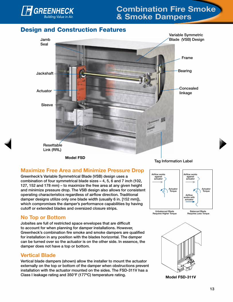
Model FSD
Bearing
Variable Symmetric Blade (VSB) Design
Sleeve
Concealed linkage
Jamb Seal
Actuator
Jackshaft
Resettable Link (RRL)
Frame
Maximize Free Area and Minimize Pressure DropGreenheck’s Variable Symmetrical Blade (VSB) design uses a combination of four symmetrical blade sizes – 4, 5, 6 and 7 inch (102, 127, 152 and 178 mm) – to maximize the free area at any given height and minimize pressure drop. The VSB design also allows for consistent operating characteristics regardless of airflow direction. Traditional damper designs utilize only one blade width (usually 6 in. [152 mm]), which compromises the damper’s performance capabilities by having cutoff or extended blades and oversized closure strips.
No Top or BottomJobsites are full of restricted space envelopes that are difficult to account for when planning for damper installations. However, Greenheck’s combination fire smoke and smoke dampers are qualified for installation in any position with the blades horizontal. The damper can be turned over so the actuator is on the other side. In essence, the damper does not have a top or bottom.
Vertical BladeVertical blade dampers (shown) allow the installer to mount the actuator externally on the top or bottom of the damper when obstructions prevent installation with the actuator mounted on the sides. The FSD-311V has a Class I leakage rating and 350°F (177ºC) temperature rating.
ActuatorTorque
ActuatorTorque
Airflow worksagainstactuator
Airflow worksagainstactuator
Airflowworks with
actuator
Unbalanced BladeRequires Higher Torque
Balanced Blade Requires Less Torque
Free AreaMaximum Reduced
Greenheckwith VSB with 6 in. blades
with 7 in. blades
unbalancedblade
Tag Information Label
Model FSD-311V
14
Combination Fire Smoke& Smoke Dampers
Design and Construction Features
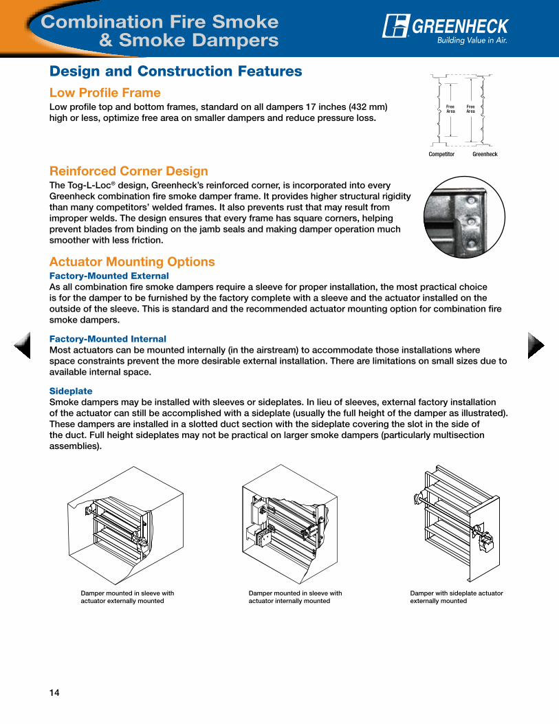
Reinforced Corner DesignThe Tog-L-Loc® design, Greenheck’s reinforced corner, is incorporated into every Greenheck combination fire smoke damper frame. It provides higher structural rigidity than many competitors’ welded frames. It also prevents rust that may result from improper welds. The design ensures that every frame has square corners, helping prevent blades from binding on the jamb seals and making damper operation much smoother with less friction.
Actuator Mounting OptionsFactory-Mounted ExternalAs all combination fire smoke dampers require a sleeve for proper installation, the most practical choice is for the damper to be furnished by the factory complete with a sleeve and the actuator installed on the outside of the sleeve. This is standard and the recommended actuator mounting option for combination fire smoke dampers.
Factory-Mounted Internal Most actuators can be mounted internally (in the airstream) to accommodate those installations where space constraints prevent the more desirable external installation. There are limitations on small sizes due to available internal space.
Sideplate Smoke dampers may be installed with sleeves or sideplates. In lieu of sleeves, external factory installation of the actuator can still be accomplished with a sideplate (usually the full height of the damper as illustrated). These dampers are installed in a slotted duct section with the sideplate covering the slot in the side of the duct. Full height sideplates may not be practical on larger smoke dampers (particularly multisection assemblies).
Low Profile FrameLow profile top and bottom frames, standard on all dampers 17 inches (432 mm) high or less, optimize free area on smaller dampers and reduce pressure loss.
Damper mounted in sleeve with actuator externally mounted
Damper mounted in sleeve with actuator internally mounted
Damper with sideplate actuator externally mounted
FreeArea
FreeArea
Competitor Greenheck
15
Combination Fire Smoke & Smoke Dampers
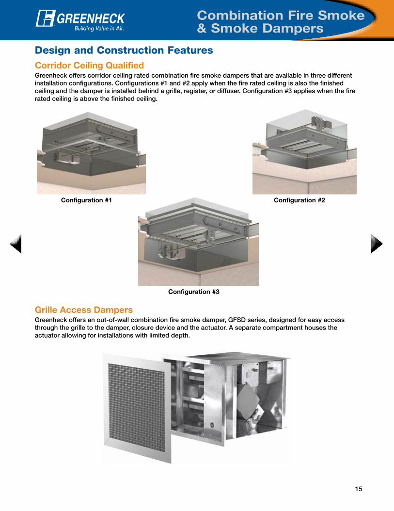
Corridor Ceiling QualifiedGreenheck offers corridor ceiling rated combination fire smoke dampers that are available in three different installation configurations. Configurations #1 and #2 apply when the fire rated ceiling is also the finished ceiling and the damper is installed behind a grille, register, or diffuser. Configuration #3 applies when the fire rated ceiling is above the finished ceiling.
Configuration #3
Configuration #1 Configuration #2
Grille Access DampersGreenheck offers an out-of-wall combination fire smoke damper, GFSD series, designed for easy access through the grille to the damper, closure device and the actuator. A separate compartment houses the actuator allowing for installations with limited depth.
Design and Construction Features
16
Combination Fire Smoke& Smoke Dampers
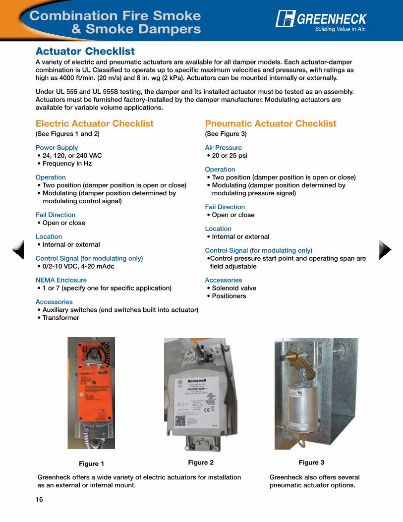
Actuator Checklist
Greenheck also offers several pneumatic actuator options.
Figure 3Figure 2
Greenheck offers a wide variety of electric actuators for installation as an external or internal mount.
Figure 1
A variety of electric and pneumatic actuators are available for all damper models. Each actuator-damper combination is UL Classified to operate up to specific maximum velocities and pressures, with ratings as high as 4000 ft/min. (20 m/s) and 8 in. wg (2 kPa). Actuators can be mounted internally or externally.
Under UL 555 and UL 555S testing, the damper and its installed actuator must be tested as an assembly. Actuators must be furnished factory-installed by the damper manufacturer. Modulating actuators are available for variable volume applications.
Electric Actuator Checklist(See Figures 1 and 2)
Power Supply • 24, 120, or 240 VAC • Frequency in Hz
Operation • Two position (damper position is open or close) • Modulating (damper position determined by modulating control signal)
Fail Direction • Open or close
Location • Internal or external
Control Signal (for modulating only) • 0/2-10 VDC, 4-20 mAdc
NEMA Enclosure • 1 or 7 (specify one for specific application)
Accessories • Auxiliary switches (end switches built into actuator) • Transformer
Pneumatic Actuator Checklist(See Figure 3)
Air Pressure • 20 or 25 psi
Operation • Two position (damper position is open or close) • Modulating (damper position determined by
modulating pressure signal)
Fail Direction • Open or close
Location • Internal or external
Control Signal (for modulating only) • Control pressure start point and operating span are
field adjustable
Accessories • Solenoid valve • Positioners
17
Combination Fire Smoke & Smoke Dampers
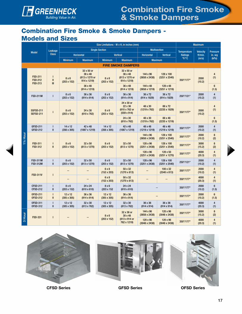
Combination Fire Smoke & Smoke Dampers -Models and Sizes
ModelLeakage
Class
Size Limitations - W x H, in inches (mm) Maximum
Single Section MultisectionTemperature
Ratings °F/°C
Velocityft/min. (m/s)
Pressurein. wg(kPa)
Horizontal Vertical Horizontal Vertical
Minimum Maximum Minimum Maximum Maximum
FIRE SMOKE DAMPERS
1½ H
our
FSD-211FSD-212FSD-213
IIIIII
8 x 6(203 x 152)
32 x 50 or 36 x 48
(813 x 1270 or914 x 1219)
8 x 6(203 x 152)
32 x 50 or36 x 48
(813 x 1270 or914 x 1219)
144 x 96(3658 x 2438)
128 x 100(3251 x 2540)
350°/177°2000(10.2)
4(1)
36 x 48(914 x 1219)
36 x 48(914 x 1219)
144 x 48(3658 x 1219)
128 x 48(3251 x 1219)
6(1.5)
FSD-211M I8 x 6
(203 x 152)36 x 36
(914 x 914)8 x 6
(203 x 152)36 x 36
(914 x 914)36 x 72
(914 x 1829)36 x 72
(914 x 1829)250°/121°
2000(10.2)
4(1)
SSFSD-211SEFSD-211
I8 x 6
(203 x 152)24 x 30
(610 x 762)8 x 6
(203 x 152)
24 x 30 or22 x 36
(610 x 762 or(559 x 914)
48 x 30(1219 x 762)
88 x 72(2235 x 1829)
350°/177°2000(10.2)
4(1)
24 x 30(610 x 762)
48 x 30(1219 x 762)
88 x 48(2235 x 1219)
6(1.5)
GFSD-211GFSD-212
III
14 x 12(356 x 305)
42 x 48(1067 x 1219)
14 x 12(356 x 305)
42 x 48(1067 x 1219)
48 x 48(1219 x 1219)
48 x 48(1219 x 1219)
350°/177°2000 (10.2)
4(1)
FSD-311FSD-312
III
8 x 6(203 x 152)
32 x 50(813 x 1270)
8 x 6(203 x 152)
32 x 50(813 x 1270)
144 x 96 (3658 x 2438)
128 x 100(3251 x 2540)
350°/177°2000 (10.2)
8 (2)
128 x 96 (3251 x 2438)
128 x 100 (3251 x 2540)
350°/177°3000 (15.2)
8 (2)
128 x 96 (3251 x 2438)
128 x 50(3251 x 1270)
350°/177°4000 (20.3)
4(1)
FSD-311MFSD-312M
III
8 x 6(203 x 152)
32 x 50(813 x 1270)
8 x 6(203 x 152)
32 x 50(813 x 1270)
128 x 96 (3251 x 2438)
128 x 100(3251 x 2540)
250°/121°2000 (10.2)
4(1)
FSD-311V I
-- --6 x 8
(152 x 203)50 x 32
(1270 x 813)--
100 x 32(2540 x 813)
350°/177°2000 (10.2)
4(1)
-- --6 x 8
(152 x 203)50 x 32
(1270 x 813)-- -- 350°/177°
4000 (20.3)
4(1)
CFSD-211CFSD-212
III
8 x 6(203 x 152)
24 x 24(610 x 610)
8 x 6(203 x 152
24 x 24(610 x 610)
-- 350°/177°2000 (10.2)
6(1.5)
OFSD-211OFSD-212
III
12 x 12(305 x 305)
36 x 36(914 x 914)
12 x 12(305 x 305)
36 x 36(914 x 914)
-- 350°/177°2000 (10.2)
6(1.5)
OFSD-311OFSD-312
III
12 x 12(305 x 305)
32 x 30(813 x 762)
12 x 12(305 x 305)
32 x 30(813 x 762)
36 x 36(914 x 914)
36 x 36(914 x 914)
350°/177°4000 (20.3)
4(1)
3 H
our
FSD-331 I -- --8 x 6
(203 x 152)
32 x 36 or 30 x 48
(813 x 914 or 762 x 1219)
144 x 96 (3658 x 2438)
120 x 96(3048 x 2438)
350°/177°3000 (15.2)
8 (2)
120 x 96 (3048 x 2438)
120 x 96 (3048 x 2438)
350°/177°4000 (20.3)
4(1)
OFSD SeriesCFSD Series GFSD Series

18
Combination Fire Smoke & Smoke Dampers
Smoke Dampers - Models and Sizes
ModelLeakage
Class
Size Limitations - W x H, in inches (mm) Maximum
Single Section MultisectionTemperature
Ratings °F /°C
Velocityft/min. (m/s)
Pressurein. wg (kPa)
Horizontal Vertical Horizontal Vertical
Minimum Maximum Minimum Maximum Maximum
SMOKE DAMPERS
SMD-201SMD-202SMD-203
IIIIII
8 x 6(203 x 152)
32 x 50 or 36 x 48
(813 x 1270 or914 x 1219)
8 x 6(203 x 152)
32 x 50 or36 x 48
(813 x 1270 or 914 x 1219)
144 x 100 or288 x 50
(3658 x 2540 or 7315 x 1270)
144 x 100 or288 x 50
(3658 x 2540 or7315 x 1270) 350°/177°
2000(10.2)
4(1)
36 x 48(914 x 1219)
36 x 48(914 x 1219)
144 x 48(3658 x 1219)
144 x 48(3658 x 1219)
6(1.5)
SMD-201M I8 x 6
(203 x 152)36 x 36
(914 x 914)8 x 6
(203 x 152)36 x 36
(914 x 914)36 x 72
(914 x 1829)36 x 72
(914 x 1829)250°/121°
2000 (10.2)
4 (1)
SESMD-201SSSMD-201
I8 x 6
(203 x 152)24 X 30
(610 x 762)8 x 6
(203 x 152)24 x 30
(610 x 762)
88 x 72 (2235 x 1829)
88 x 72 (2235 x 1829)
350°/177°2000(10.2)
4(1)
88 x 48(2235 x 1219)
88 x 48(2235 x 1219)
6(1.5)
SMD-301SMD-302
III
8 x 6(203 X 152)
32 x 50(813 x 1270)
8 x 6(203 x 152)
32 x 50(813 x 1270)
192 x 100(4877 x 2540)
192 x 100(3251 x 2540)
350°/177°
2000(10.2)
4(1)
192 x 72 or 128 x 100
(4877 x 1270 or 3251 x 2540)
192 x 72 or 128 x 100
(4877 x 1270 or 3251 x 2540)
8 (2)
192 x 72 or 128 x 100
(4877 x 1270 or 3251 x 2540)
192 x 72 or 128 x 100
(4877 x 1270 or 3251 x 2540)
3000(15.2)
8(2)
192 x 50(4877 x 1270)
192 x 50(4877 x 1270)
4000(20.3)
4(1)
SMD-301MSMD-302M
III
8 x 6(203 x 152)
32 x 50(813 x 1270)
8 x 6(203 x 152)
32 x 50(813 x 1270)
128 x 100 (3251 x 2540)
128 x 100 (3251 x 2540)
250°/121°2000 (10.2)
4(1)
SMD-301V I -- --6 x 8
(152 x 203)50 x 32
(1270 x 813)
--100 x 32
(2540 x 813)350°/177°
2000(10.2)
4(1)
-- --4000(20.3)
4(1)
SMD-401 I8 x 8
(203 x 203)
48 x 60(1219 x 1524) 8 x 8
(203 x 203)
48 x 60(1219 x 1524)
192 x 120(4877 x 3048)
192 x 120(4877 x 3048)
250°/121°
2000(10.2)
4(1)
48 x 36(1219 x 914)
48 x 36(1219 x 914)
192 x 72(4877 x 1829)
192 x 72(4877 x 1829)
3000(15.2)
6(1.5)
SMD-401EF I8 x 6
(203 x 152)
48 x 48 (1219 x 1219) 8 x 6
(203 x 152)
48 x 48 (1219 x 1219)
192 x 120 (4877 x 3048)
192 x 120 (4877 x 3048)
250°/121°
2000 (10.2)
4 (1)
36 x 48 (914 x 1219)
36 x 48 (914 x 1219)
144 x 96 (3658 x 2438)
144 x 96 (3658 x 2438)
3000 (15.2)
6 (1.5)
SMD-401M I8 x 8
(203 x 203)36 x 36
(914 x 914)8 x 8
(203 x 203)36 x 36
(914 x 914)36 x 72
(914 x 1829)36 x 72
(914 x 1829)250°/121°
2000(10.2)
4 (1)
HSD-401 I6 x 61/4
(152 x 159)60 x 60
(1524 x 1524)6 x 61/4
(152 x 159)60 x 60
(1524 x 1524)240 x 120
(6096 x 3048)240 x 120
(6096 x 3048)250°/121°
3000(15.2)
6(1.5)
SMD-201 SMD-301V HSD-401

19
Round UL Dampers
Quick Reference Guide
MountingRound fire, smoke and combination fire smoke dampers are available for mounting either vertically or horizontally. Only one retainer plate is required for mounting of damper. Dampers are supplied with sleeves from the factory and can be installed without the need for additional field installed sleeves.
Retainer Plate
Duct ConnectionArea
2 in .
AIRFLOW
6 in. max.TW
Sleeve Length
6 in. max.
Do not place retainerplate in this groove
2 in .
Duct connectionArea
Clearance for expansion
Retainer plate
Blade latch
Access door to be onsame side as blade latch
X = StandardO = Optional
Type MaterialUL 555
FireRating
UL 555S Leakage
ClassClosure Device Closure Temperature Accessories
Fire
Sm
oke
Co
mb
inat
ion
Fire
Sm
oke
Gal
vani
zed
Ste
el
304
Sta
inle
ss S
teel
316
Sta
inle
ss S
teel
1½ H
our
Cla
ss I
Cla
ss II
Fus
ible
Lin
k
RR
L
RR
L/O
CI
TO
R
PR
V
165°
F (
74°C
)
212°
F (
100°
C)
286°
F (
141°
C)
350°
F (
177°
C)
Ret
aini
ng P
late
s
Mo
men
tary
Tes
t S
witc
h
Tran
sfo
rmer
Gre
enhe
ck T
est
Sw
itch
(GT
S)
Sm
oke
Det
ecto
r
Op
en C
lose
Ind
icat
or
(OC
I)
DFDR-510 X X X X X O O O O
FDR-510 X X X X X O O O O
FSDR-511 X X X X X O O O O X O O O O O O O O
FSDR-512 X X X X X O O O O X O O O O O O O O
SEFSDR-511 X X X X X O O O O X O O O O O O O O
SESMDR-501 X X X O O O O
SMDR-501 X X X O O O O
SMDR-502 X X X O O O O
SSDFDR-510 X X X X X O O O O
SSFDR-510 X X X X X O O O O
SSFSDR-511 X X X X X O O O O X O O O O O O O O
SSFSDR-512 X X X X X O O O O X O O O O O O O O
SSSMDR-501 X X X O O O O

20
Round UL Dampers
Model TypeMounting
Horizontal or Vertical(H or V)
Maximum
Temperature°F/°C
Diameterin. (mm)
Velocityft/min. (m/s)
Pressurein. wg (kPa)
FDR-510 Static Fire H or V - 24 (610) - -
SSFDR-510 Static Fire H or V - 24 (610) - -
DFDR-510 Dynamic Fire H or V 286°/141° 24 (610) 2000 (10.2) 4 (1)
SSDFDR-510 Dynamic Fire H or V 286°/141° 24 (610) 2000 (10.2) 4 (1)
FSDR-511, 512 Fire Smoke H or V 350°/177° 24 (610) 3000 (15.2) 4 (1)
SSFSDR-511, 512 Fire Smoke H or V 350°/177° 24 (610) 3000 (15.2) 4 (1)
SEFSDR-511 Fire Smoke H or V 350°/177° 24 (610) 3000 (15.2) 4 (1)
SMDR-501, 502 Smoke H or V 350°/177° 24 (610) 3000 (15.2) 4 (1)
SESMDR-501 Smoke H or V 350°/177° 24 (610) 3000 (15.2) 4 (1)
SSSMDR-501 Smoke H or V 350°/177° 24 (610) 3000 (15.2) 4 (1)
Round UL Dampers - Models and Sizes
Square one-piece retaining plates easily wrap around the sleeve of the damper and tighten with the clamping screw for simplified installation. They are designed to mount flush to the wall/floor and hold the damper in the opening. One retaining plate is provided standard with the damper. A second optional plate is available for two-sided plate installations.
Retaining Plates
Blade Orientation
Normal
Axle
30° Off Horizontal(Maximum)
Axle
30°
30° Off Horizontal(Maximum)
Axle
30°
Design and Construction Features
OPENING + 2.00 MIN.
FASTENERS
WALL/FLOOR
1.00 TYP.
= Nominal size + 7/8 Min.
OPENING
Clamping Screw
Retaining PlateAssembly
Nut
SCREWCLAMPING
21
Ceiling Radiation Dampers
Design and Construction Features
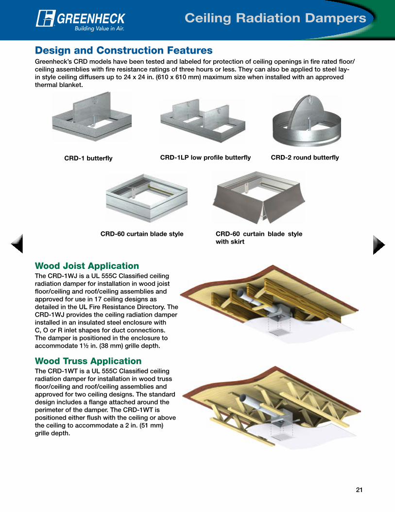
CRD-1 butterfly CRD-2 round butterfly
CRD-60 curtain blade style CRD-60 curtain blade style with skirt
Greenheck’s CRD models have been tested and labeled for protection of ceiling openings in fire rated floor/ceiling assemblies with fire resistance ratings of three hours or less. They can also be applied to steel lay-in style ceiling diffusers up to 24 x 24 in. (610 x 610 mm) maximum size when installed with an approved thermal blanket.
CRD-1LP low profile butterfly
Wood Joist ApplicationThe CRD-1WJ is a UL 555C Classified ceiling radiation damper for installation in wood joist floor/ceiling and roof/ceiling assemblies and approved for use in 17 ceiling designs as detailed in the UL Fire Resistance Directory. The CRD-1WJ provides the ceiling radiation damper installed in an insulated steel enclosure with C, O or R inlet shapes for duct connections. The damper is positioned in the enclosure to accommodate 1½ in. (38 mm) grille depth.
Wood Truss ApplicationThe CRD-1WT is a UL 555C Classified ceiling radiation damper for installation in wood truss floor/ceiling and roof/ceiling assemblies and approved for two ceiling designs. The standard design includes a flange attached around the perimeter of the damper. The CRD-1WT is positioned either flush with the ceiling or above the ceiling to accommodate a 2 in. (51 mm) grille depth.

22
Ceiling Radiation Dampers
Design & Construction Features
Ceiling Radiation Dampers - Models and Sizes
OptionsVolume Controller - A volume controller gives you the ability to regulate airflow thru the damper by manually setting the blades to a given angle. Adjusting the screw will open or close the blades.
Frame Extensions - Top, bottom or top/bottom frame extensions are available on CRD-1, CRD-1LP and CRD-2.
Thermal Blankets - Greenheck offers two different types of thermal blankets with ceiling radiation dampers to be used as batt and blanket material. QB-24 is a refractory thermal blanket consisting of a non-asbestos high temperature ceramic fiber blanket quilted between two layers of fiberglass cloth. TB-24 is a non-asbestos mineral wool thermal blanket.
Type Butterfly Style Curtain Style Round
Model CRD-1CRD-1LP
Low ProfileCRD-1WJ CRD-1WT CRD-60 CRD-60X CRD-2 CRD-501
Minimum Sizein. (mm)
4 x 6(102 x 152)
4 x 12(102 x 305)
4 x 6(102 x 152)
4 x 6(102 x 152)
6 x 4(152 x 102)
6 x 4(152 x 102)
5(127)
6(152)
Maximum Sizein. (mm)
24 x 24(610 x 610)
24 x 24(610 x 610)
16 x 12(406 x 305)
21 x 18(533 x 457)
24 x 24(610 x 610)
24 x 24(610 x 610)
24(610)
12(305)
Volume Controller
Low Leakage Ceiling Radiation DamperThe CRD-501 is a round ceiling radiation damper with a Class I Smoke Leakage Rating. It is UL Classified as a ceiling radiation (UL 555C) and as a smoke damper (UL 555S). As a UL 555C ceiling radiation, it is used in floor/ceiling and roof/ceiling assemblies to maintain the fire resistance integrity of the assembly during fire exposure. As a UL 555S smoke damper, Model CRD-501 is a Class I smoke leakage rated damper designed to control the spread of smoke.
CRD-501

23
Life Safety Dampers
Tag LabelGreenheck labels—on all dampers—include the tag information for your order. This label provides the damper model, size, actuator model, and purchase order number. This label will help save time in the field when you have multiple locations for dampers on the jobsite. On combination fire smoke, smoke and fire dampers, you will see a QR code on the label too. When you scan the QR code with your smartphone, you will be directed to www.greenheck.com for model specific information.
Helpful Installation DecalsGreenheck dampers feature decals highlighting damper areas that are important to an accurate installation. Our decals point out critical damper areas and include messages to make installation hassle-free. We are the only damper manufacturer to offer these simple, yet very helpful tips, right on the damper.
Installation & Convenience Features
Installation BookletsGreenheck includes installation booklets in every shipment of dampers. These booklets include installation guidelines such as field-supplied sleeves, single side retaining angles, and much more to help with your installation needs.
One Piece Retaining AnglesGreenheck’s one piece retaining angle, the POC (literally named for being a “Piece of Cake”) makes combination fire smoke damper installation a breeze. The POC simply wraps around the sleeve of the damper, connections are made as described in our installation instructions, and that’s it! Simple! Like their rectangular counterparts, round one-piece retaining plates easily wrap around the sleeve of the damper and tighten with the clamping screw for simplified installation.
Maximum Qualified Damper Size for Single Side and 3-side* Retaining Angle
(Width x Height)
Mounting Inches Millimeters
Vertical*80 x 50 2032 x 1270
50 x 80 1270 x 2032
40 x 100 1016 x 2540
Horizontal 144 x 96 3658 x 2438
Round Fire and Fire Smoke
24 diameter 610 diameter
Single Side Retaining Angles and PlatesRectangular dampers and sleeve assemblies are qualified for installations with retaining angles on one side of the partition only. Round dampers and sleeve assemblies may be installed with retaining plates on one side only. Damper assemblies exceeding these maximum sizes must be secured with retaining angles or plates on both sides of the partition.
A 3-side retaining angle is qualified in applications where the damper rests directly on the base of the wall opening (example: underfloor application). A retaining angle is not required on the bottom side of the damper.
Retaining Plate
24
Life Safety Dampers
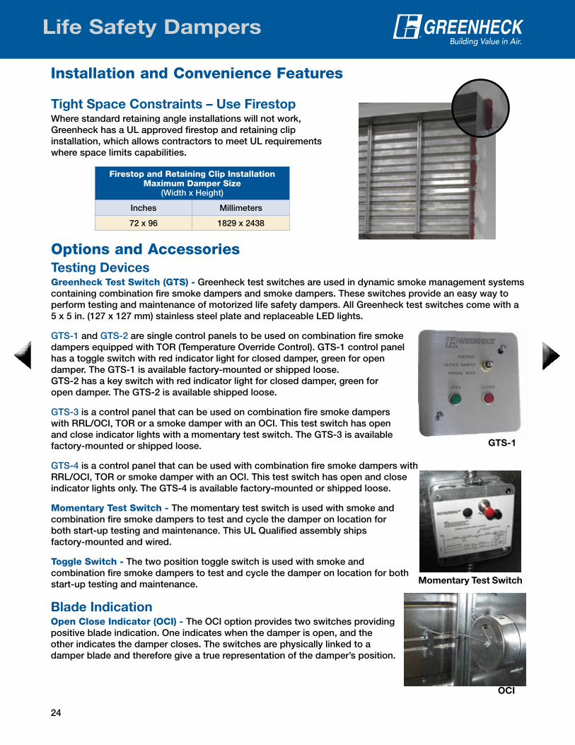
Blade IndicationOpen Close Indicator (OCI) - The OCI option provides two switches providing positive blade indication. One indicates when the damper is open, and the other indicates the damper closes. The switches are physically linked to a damper blade and therefore give a true representation of the damper’s position.
Installation and Convenience Features
Options and Accessories
Tight Space Constraints – Use FirestopWhere standard retaining angle installations will not work, Greenheck has a UL approved firestop and retaining clip installation, which allows contractors to meet UL requirements where space limits capabilities.
Firestop and Retaining Clip InstallationMaximum Damper Size
(Width x Height)
Inches Millimeters
72 x 96 1829 x 2438
Testing DevicesGreenheck Test Switch (GTS) - Greenheck test switches are used in dynamic smoke management systems containing combination fire smoke dampers and smoke dampers. These switches provide an easy way to perform testing and maintenance of motorized life safety dampers. All Greenheck test switches come with a 5 x 5 in. (127 x 127 mm) stainless steel plate and replaceable LED lights.
GTS-1 and GTS-2 are single control panels to be used on combination fire smoke dampers equipped with TOR (Temperature Override Control). GTS-1 control panel has a toggle switch with red indicator light for closed damper, green for open damper. The GTS-1 is available factory-mounted or shipped loose. GTS-2 has a key switch with red indicator light for closed damper, green for open damper. The GTS-2 is available shipped loose.
GTS-3 is a control panel that can be used on combination fire smoke dampers with RRL/OCI, TOR or a smoke damper with an OCI. This test switch has open and close indicator lights with a momentary test switch. The GTS-3 is available factory-mounted or shipped loose.
GTS-4 is a control panel that can be used with combination fire smoke dampers with RRL/OCI, TOR or smoke damper with an OCI. This test switch has open and close indicator lights only. The GTS-4 is available factory-mounted or shipped loose.
Momentary Test Switch - The momentary test switch is used with smoke and combination fire smoke dampers to test and cycle the damper on location for both start-up testing and maintenance. This UL Qualified assembly ships factory-mounted and wired.
Toggle Switch - The two position toggle switch is used with smoke and combination fire smoke dampers to test and cycle the damper on location for both start-up testing and maintenance.
GTS-1
Momentary Test Switch
OCI

25
Life Safety Dampers
Options and AccessoriesClosure DevicesResettable Link (RRL) - The RRL replaces the fusible link with a bimetal heat responsive device that is easily reset from outside the duct. This allows routine testing of a damper without the need to replace a fusible link. It also ensures controlled closure of the damper, eliminating the possibility of duct damage resulting from sudden instantaneous type closures. RRL options are available with temperature ratings of 165ºF (74ºC), 212ºF (100ºC), 250ºF (121ºC) and 350ºF (177ºC).
Resettable Link with Open Closed Indicator (RRL/OCI) - The RRL/OCI combines the resettable link (RRL) and the open close indicator (OCI) into one device. RRL/OCI option is available with temperature ratings of 165ºF (74ºC), 212ºF (100ºC), 250ºF (121ºC) and 350ºF (177ºC).
Pneumatic Relief Valve (PRV) - The PRV is a heat responsive device that activates when temperatures in excess of 165°F (74°C) or 212°F (100°C) are detected. When the fusible link melts, air from the actuator is exhausted to close the damper. No electrical connection is required. The PRV must be installed at the factory and cannot be added in the field. An alternative to the PRV is a RRL with EP switch, which requires an electrical connection.
Temperature Override Control (TOR) - The TOR option provides damper closure, usually at 165°F (74°C), with the ability to override this closure (reopen damper) so the duct system can accomplish its intended smoke control system functions as long as the temperature at the damper does not exceed the secondary heat responsive device setting, usually 350°F (177°C).
Electro-Pneumatic Switch (EP) - This is also known as a three-way solenoid valve, and is used to electronically open and close a pneumatic actuated damper. It is wired in series with a normally closed thermostat when used with a fire smoke damper to initiate closure at elevated temperatures. It can also be used on a smoke damper to initiate closure when required in a smoke control system.
Security BarsWhen a specification requires security bars to be installed with the damper, they can be shipped assembled. Installation of security bars into dampers reduces security risks and reinforces the equipment. Security bars maintain the UL Classification for all products and are welded into the sleeve. Two types of security bars are available:
• Cross bar - round steel bars placed horizontal and vertical on center, based on customer selection or
• Punched mid bar - round steel bars placed vertical on center, based on customer selection, with flat mid bars placed horizontal on dampers higher than 24 inches (610 mm).
RRL
RRL/OCI
PRV
TOR
EP Switch

26
Life Safety Dampers
Smoke DetectorsA smoke detector’s purpose is to sample air currents passing through a duct and upon alarm, provide management of fans, blowers, combination fire smoke dampers and smoke dampers.
Smoke Detector - These photoelectric smoke detectors sample air currents passing through a duct and give dependable performance for management of smoke and combination fire smoke dampers. There are two smoke detectors available:
1. The DH-98-P is rated for air velocities from 300 - 4000 ft/min. (1.5 - 20.3 m/s).
2. The D4120 is rated for air velocities from 100 - 4000 ft/min. (0.5 - 20.3 m/s)
These smoke detectors can either be factory-mounted and wired or shipped loose.
Options and Accessories
TransitionsWhen a rectangular combination fire smoke or smoke damper is being used in conjunction with round or oval ductwork, it must be supplied with round or oval transitions on one or both ends of the sleeve. A Type C transition may be used to increase free area and minimize pressure drop. Dampers should be ordered to the duct dimensions.
Clean WrapIn the Indoor Air Quality section of the Green Building and LEED Core Concepts Guide, you need to protect air quality during construction and prevent dust and particulate buildup. Greenheck offers Clean Wrap to help meet this requirement. Clean Wrap is a thin film that adheres to the ends of the damper sleeve to prevent dust, dirt and debris from entering the damper at the construction site.
No Flow Smoke Detector - The no flow smoke detector is rated for systems without a minimum operating velocity. This smoke detector is rated for air velocities from 0 to 3000 ft/min. (0 to 15.2 m/s) and is mounted internally to the damper sleeve. It can be used on dampers with a maximum of two actuators. The no flow smoke detector has a built-in test switch.
Type R Type O Type C
No flow
Low flow
Low flow

27
Life Safety Dampers
Access DoorsAccording to NFPA 80 and NFPA 90A, an access door needs to be provided in air ducts adjacent to each fire damper, smoke damper,or combination fire smoke damper for maintenance and inspection.
Save time and money by letting Greenheck install the access door in the sleeve to save on labor costs in the field.
Factory-Mounted Accessories
Retaining AngleSave time by letting Greenheck install retaining angles for you. You can order your retaining angles four different ways:
• Single Fastened - one retaining angle mounted in the location you want
• Single Wrapped - one retaining angle wrapped around the damper sleeve and wire tied
• Double Wrapped - the same feature as single wrapped, but with 2 sets of retaining angles
• Fastened and Wrapped - one retaining angle fastened and one angle wrapped around the damper
Quick Connect Breakaway ConnectionsGreenheck was the first manufacturer to successfully UL Qualify a universal breakaway duct connection that is compatible with TDC, TDF, Ductmate, Nexus or Ward flange systems. You now have the option to choose the universal breakaway connection on fire dampers, smoke, and combination fire smoke dampers. You can order your dampers with breakaway connection three different ways:
• Universal flange attached to one end of the sleeve • Universal flange attached to both ends of the sleeve • One end attached and one shipped loose
S and Drive connection uses drive slip connection on the side of the hemmed sleeve and S-slip joints are used on top and bottom.
To see the UL 555 Duct Impact Test (Quick Connect Breakaway Test) video, go to www.greenheck.com/library/videos.

28
Life Safety Dampers
Damper Performance Testing CriteriaPressure drop testing was conducted in accordance with AMCA Standard 500-D using the three configurations shown. All data has been corrected to represent standard air at a density of .075 lb/ft3 (1.201 kg/m3 ).
Actual pressure drop found in any HVAC system is a combination of many factors. This pressure drop information along with an analysis of other system influences should be used to estimate actual pressure losses for a damper installed in a given HVAC system.
5D 6D
Figure 5.3
Figure 5.2
5D
Figure 5.5
4 (W) (H)D=3.14
D = Duct lengthW = Damper widthH = Damper height
Figure 5.3 Illustrates a fully ducted damper. This configuration has the lowest pressure drop of the three test configurations because entrance and exit losses are minimized by straight duct runs upstream and downstream of the damper.
Figure 5.2 Illustrates a ducted damper exhausting air into an open area. This configuration has a lower pressure drop than Figure 5.5 because entrance losses are minimized by a straight duct run upstream of the damper.
Figure 5.5 Illustrates a plenum mounted damper. This configuration has the highest pressure drop because of extremely high entrance and exit losses due to the sudden changes of area in the system.
Greenheck Fan Corporation certifies that the models CFSD-211, 212; DFD-210; DFDAF-310, 330; SEDFD-210; FSD-211, 211M, 212, 213, 311, 311M, 312, 312M, 331; SSFSD-211; SEFSD-211; OFSD-211, 212, 311, 312; SMD-201, 201M, 202, 203, 301, 302, 301M, 302M; SESMD-201 and SSSMD-201 shown herein are licensed to bear the AMCA Seal. The ratings shown are based on tests and procedures performed in accordance with AMCA Publication 511 and comply with the requirements of the AMCA Certified Ratings Programs. The AMCA Certified Ratings Seal applies to air performance only.
29
Life Safety Dampers
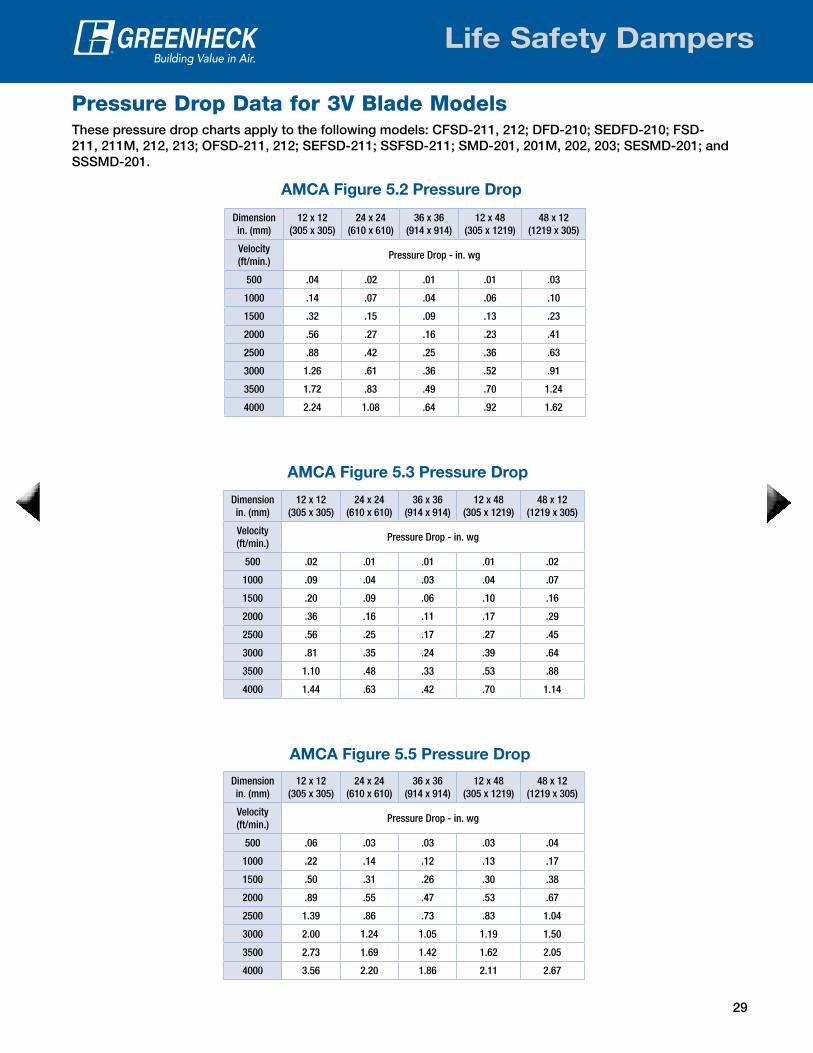
Pressure Drop Data for 3V Blade ModelsThese pressure drop charts apply to the following models: CFSD-211, 212; DFD-210; SEDFD-210; FSD-211, 211M, 212, 213; OFSD-211, 212; SEFSD-211; SSFSD-211; SMD-201, 201M, 202, 203; SESMD-201; and SSSMD-201.
Dimension in. (mm)
12 x 12(305 x 305)
24 x 24(610 x 610)
36 x 36(914 x 914)
12 x 48(305 x 1219)
48 x 12(1219 x 305)
Velocity (ft/min.)
Pressure Drop - in. wg
500 .04 .02 .01 .01 .03
1000 .14 .07 .04 .06 .10
1500 .32 .15 .09 .13 .23
2000 .56 .27 .16 .23 .41
2500 .88 .42 .25 .36 .63
3000 1.26 .61 .36 .52 .91
3500 1.72 .83 .49 .70 1.24
4000 2.24 1.08 .64 .92 1.62
AMCA Figure 5.2 Pressure Drop
Dimension in. (mm)
12 x 12(305 x 305)
24 x 24(610 x 610)
36 x 36(914 x 914)
12 x 48(305 x 1219)
48 x 12(1219 x 305)
Velocity (ft/min.)
Pressure Drop - in. wg
500 .02 .01 .01 .01 .02
1000 .09 .04 .03 .04 .07
1500 .20 .09 .06 .10 .16
2000 .36 .16 .11 .17 .29
2500 .56 .25 .17 .27 .45
3000 .81 .35 .24 .39 .64
3500 1.10 .48 .33 .53 .88
4000 1.44 .63 .42 .70 1.14
AMCA Figure 5.3 Pressure Drop
Dimension in. (mm)
12 x 12(305 x 305)
24 x 24(610 x 610)
36 x 36(914 x 914)
12 x 48(305 x 1219)
48 x 12(1219 x 305)
Velocity (ft/min.)
Pressure Drop - in. wg
500 .06 .03 .03 .03 .04
1000 .22 .14 .12 .13 .17
1500 .50 .31 .26 .30 .38
2000 .89 .55 .47 .53 .67
2500 1.39 .86 .73 .83 1.04
3000 2.00 1.24 1.05 1.19 1.50
3500 2.73 1.69 1.42 1.62 2.05
4000 3.56 2.20 1.86 2.11 2.67
AMCA Figure 5.5 Pressure Drop

30
Life Safety Dampers
Pressure Drop Data for Airfoil Blade Models
Dimension in. (mm)
12 x 12(305 x 305)
24 x 24(610 x 610)
36 x 36(914 x 914)
12 x 48(305 x 1219)
48 x 12(1219 x 305)
Velocity (ft/min.)
Pressure Drop - in. wg
500 .03 .01 .01 .01 .02
1000 .12 .06 .06 .05 .08
1500 .26 .12 .12 .12 .18
2000 .46 .22 .22 .21 .32
2500 .72 .34 .34 .33 .51
3000 1.04 .49 .49 .48 .74
3500 1.41 .67 .67 .65 1.00
4000 1.84 .87 .88 .85 1.31
AMCA Figure 5.2 Pressure Drop
Dimension in. (mm)
12 x 12(305 x 305)
24 x 24(610 x 610)
36 x 36(914 x 914)
12 x 48(305 x 1219)
48 x 12(1219 x 305)
Velocity (ft/min.)
Pressure Drop - in. wg
500 .05 .03 .03 .03 .04
1000 .18 .13 .12 .13 .15
1500 .41 .30 .27 .29 .33
2000 .73 .53 .47 .51 .58
2500 1.14 .83 .74 .80 .91
3000 1.65 1.20 1.06 1.15 1.31
3500 2.24 1.64 1.44 1.57 1.79
4000 2.93 2.14 1.88 2.05 2.33
AMCA Figure 5.5 Pressure Drop
Dimension in. (mm)
12 x 12(305 x 305)
24 x 24(610 x 610)
36 x 36(914 x 914)
12 x 48(305 x 1219)
48 x 12(1219 x 305)
Velocity (ft/min.)
Pressure Drop - in. wg
500 .01 .01 .01 .01 .01
1000 .06 .03 .02 .03 .05
1500 .13 .06 .05 .07 .10
2000 .23 .11 .10 .12 .18
2500 .36 .17 .15 .18 .29
3000 .52 .24 .22 .26 .41
3500 .71 .33 .29 .36 .56
4000 .92 .43 .38 .47 .74
AMCA Figure 5.3 Pressure Drop
These pressure drop charts apply to the following models: DFDAF-310, 330; FSD-311, 311M; FSD-312, 312M; FSD-331; OFSD-311, 312; SMD-301, 302; SMD-301M and 302M.

31
Life Safety Dampers
Dimension in. (mm)
12 x 12(305 x 305)
24 x 24(610 x 610)
36 x 36(914 x 914)
12 x 48(305 x 1219)
48 x 12(1219 x 305)
Velocity (ft/min.)
Pressure Drop - in. wg
500 .03 .02 .016 .025 .025
1000 .11 .08 .06 .10 .09
1500 .26 .17 .15 .21 .20
2000 .48 .31 .26 .38 .37
2500 .72 .49 .41 .58 .58
3000 1.02 .70 .59 .83 .85
3500 1.40 .94 .80 1.18 1.17
4000 1.84 1.27 1.04 1.55 1.58
AMCA Figure 5.2 Pressure Drop
Dimension in. (mm)
12 x 12(305 x 305)
24 x 24(610 x 610)
36 x 36(914 x 914)
12 x 48(305 x 1219)
48 x 12(1219 x 305)
Velocity (ft/min.)
Pressure Drop - in. wg
500 .047 .04 .036 .046 .038
1000 .19 .16 .14 .18 .15
1500 .43 .36 .34 .41 .35
2000 .72 .65 .60 .72 .63
2500 1.18 .98 .92 1.14 .97
3000 1.66 1.45 1.31 1.61 1.40
3500 2.3 1.97 1.85 2.25 1.92
4000 3.3 2.64 2.37 2.95 2.54
AMCA Figure 5.5 Pressure Drop
Dimension in. (mm)
12 x 12(305 x 305)
24 x 24(610 x 610)
36 x 36(914 x 914)
12 x 48(305 x 1219)
48 x 12(1219 x 305)
Velocity (ft/min.)
Pressure Drop - in. wg
500 .01 .006 .004 .001 .001
1000 .04 .03 .02 .04 .04
1500 .09 .05 .04 .09 .09
2000 .17 .10 .07 .16 .15
2500 .27 .15 .11 .24 .23
3000 .38 .23 .16 .36 .33
3500 .52 .29 .21 .49 .45
4000 .69 .40 .28 .63 .60
AMCA Figure 5.3 Pressure Drop
Pressure Drop Data for Dynamic Curtain Fire DampersThese pressure drop charts apply to the following models: DFD-110, 150, 310, 350; DFD-150X series; ODFD-150; SSDFD-150 and 350.
32
Life Safety Dampers
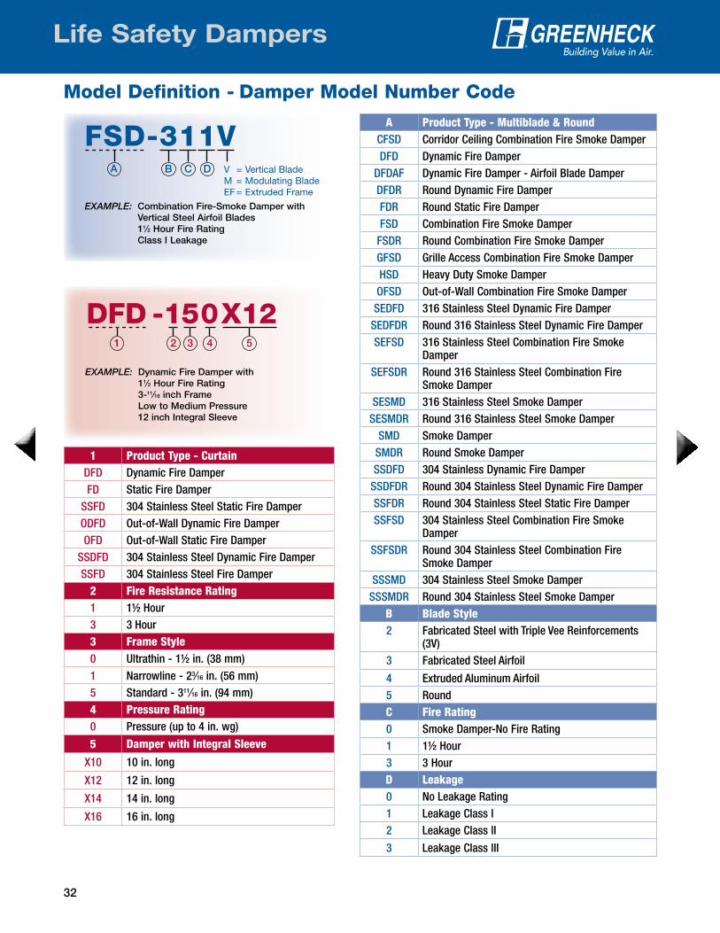
Model Definition - Damper Model Number Code
EXAMPLE: Dynamic Fire Damper with 11⁄2 Hour Fire Rating 3-11⁄16 inch Frame Low to Medium Pressure 12 inch Integral Sleeve
A Product Type - Multiblade & RoundCFSD Corridor Ceiling Combination Fire Smoke DamperDFD Dynamic Fire Damper
DFDAF Dynamic Fire Damper - Airfoil Blade DamperDFDR Round Dynamic Fire DamperFDR Round Static Fire DamperFSD Combination Fire Smoke Damper
FSDR Round Combination Fire Smoke DamperGFSD Grille Access Combination Fire Smoke DamperHSD Heavy Duty Smoke DamperOFSD Out-of-Wall Combination Fire Smoke DamperSEDFD 316 Stainless Steel Dynamic Fire Damper
SEDFDR Round 316 Stainless Steel Dynamic Fire DamperSEFSD 316 Stainless Steel Combination Fire Smoke
DamperSEFSDR Round 316 Stainless Steel Combination Fire
Smoke DamperSESMD 316 Stainless Steel Smoke Damper
SESMDR Round 316 Stainless Steel Smoke DamperSMD Smoke Damper
SMDR Round Smoke DamperSSDFD 304 Stainless Dynamic Fire Damper
SSDFDR Round 304 Stainless Steel Dynamic Fire DamperSSFDR Round 304 Stainless Steel Static Fire DamperSSFSD 304 Stainless Steel Combination Fire Smoke
DamperSSFSDR Round 304 Stainless Steel Combination Fire
Smoke DamperSSSMD 304 Stainless Steel Smoke Damper
SSSMDR Round 304 Stainless Steel Smoke DamperB Blade Style2 Fabricated Steel with Triple Vee Reinforcements
(3V)3 Fabricated Steel Airfoil
4 Extruded Aluminum Airfoil5 Round C Fire Rating0 Smoke Damper-No Fire Rating1 11/2 Hour3 3 HourD Leakage0 No Leakage Rating1 Leakage Class l2 Leakage Class lI
3 Leakage Class lII
1 Product Type - CurtainDFD Dynamic Fire DamperFD Static Fire Damper
SSFD 304 Stainless Steel Static Fire DamperODFD Out-of-Wall Dynamic Fire DamperOFD Out-of-Wall Static Fire Damper
SSDFD 304 Stainless Steel Dynamic Fire DamperSSFD 304 Stainless Steel Fire Damper
2 Fire Resistance Rating1 11/2 Hour3 3 Hour3 Frame Style0 Ultrathin - 11/2 in. (38 mm)1 Narrowline - 23⁄16 in. (56 mm)5 Standard - 311⁄16 in. (94 mm)4 Pressure Rating0 Pressure (up to 4 in. wg)
5 Damper with Integral Sleeve
X10 10 in. long
X12 12 in. long
X14 14 in. long
X16 16 in. long
DFD -150X121 2 3 4 5
EXAMPLE: Combination Fire-Smoke Damper with Vertical Steel Airfoil Blades 11⁄2 Hour Fire Rating Class I Leakage
FSD-311VV = Vertical BladeM = Modulating BladeEF = Extruded Frame
A B C D
33
Life Safety Dampers
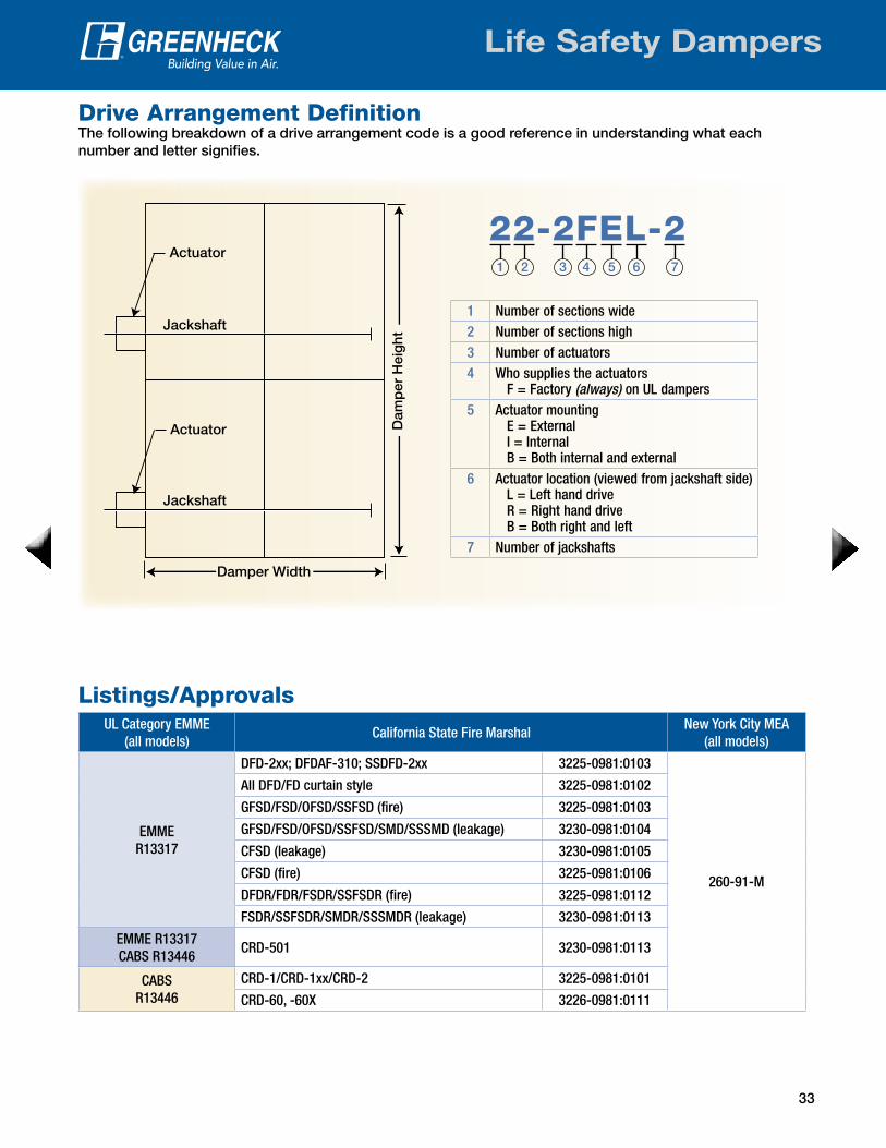
Drive Arrangement DefinitionThe following breakdown of a drive arrangement code is a good reference in understanding what each number and letter signifies.
Listings/Approvals
1 Number of sections wide2 Number of sections high3 Number of actuators4 Who supplies the actuators
F = Factory (always) on UL dampers5 Actuator mounting
E = External I = Internal B = Both internal and external
6 Actuator location (viewed from jackshaft side) L = Left hand drive R = Right hand drive B = Both right and left
7 Number of jackshafts
Damper Width
Dam
per
Hei
ght
Actuator
Jackshaft
Jackshaft
Actuator22-2FEL-2
1 2 3 4 5 6 7
UL Category EMME (all models)
California State Fire MarshalNew York City MEA
(all models)
EMME R13317
DFD-2xx; DFDAF-310; SSDFD-2xx 3225-0981:0103
260-91-M
All DFD/FD curtain style 3225-0981:0102
GFSD/FSD/OFSD/SSFSD (fire) 3225-0981:0103
GFSD/FSD/OFSD/SSFSD/SMD/SSSMD (leakage) 3230-0981:0104
CFSD (leakage) 3230-0981:0105
CFSD (fire) 3225-0981:0106
DFDR/FDR/FSDR/SSFSDR (fire) 3225-0981:0112
FSDR/SSFSDR/SMDR/SSSMDR (leakage) 3230-0981:0113
EMME R13317CABS R13446
CRD-501 3230-0981:0113
CABS R13446
CRD-1/CRD-1xx/CRD-2 3225-0981:0101
CRD-60, -60X 3226-0981:0111

34
Life Safety Dampers
Test Standards & CertificationsUnderwriters Laboratories®
UL 555 - This standard governs fire and combination fire smoke dampers which are intended for use where air ducts penetrate or terminate at openings in walls or partitions, in air transfer openings in partitions, and where air ducts extend through floors as specified in the Standard for Installation of Air-Conditioning and Ventilating Systems, NFPA 90A. In a fire emergency the fire damper is designed to close and prevent the spread of fire from one side of the wall or partition to the other. Testing includes cycling, salt spray, dust loading, dynamic closure, fire endurance, and hose stream.
UL 555C - This standard governs ceiling dampers which are intended for use in air handling duct outlets which penetrate membrane ceilings of hourly fire rated resistive assemblies, or for installation in the ceiling membrane of such assemblies which utilize the plenum space for return air.
UL 555S - This standard governs smoke and combination fire smoke dampers which are intended to prevent the spread of smoke when HVAC systems shut down during a fire emergency and those which control the movement of smoke within a building when the HVAC system functions in a smoke control mode. Leakage rated dampers are intended for installation in accordance with NFPA 90A. Testing includes salt spray, dust loading, cycling, temperature degradation, operation while under heated airflow, and elevated temperature leakage.
AMCAThe AMCA Certified Rating Program seal assures you that a product line has been tested to the appropriate AMCA standards in accordance with a legal license agreement and that the manufacturer’s catalogued certified ratings have been submitted to AMCA for approval.
Warnock Hersey®
The Warnock Hersey mark is among the most well-recognized and respected North American marks of compliance for building codes, association criteria, and product safety and performance standards. Warnock Hersey, like UL, is an independent agency that evaluates and tests products to recognized standards including those dictated by UL, NFPA, and ASTM.
CodesGreenheck smoke and combination fire smoke dampers meet the requirements established by: • ICC (International Building Code) • ICBO (International Conference of Building Officials) • IMC (International Mechanical Code) • NFPA (National Fire Protection Association) 80, 90A,
92A, 92B, 101 and 105
456935
COMBINATION FIRE/SMOKE DAMPERS
DFD, FSD, SSDFD, SSFSD,ODFD, OFSD, OSSDFD, OSSFSD
Greenheck Fan Corporation
#3230-0981:110NYC MEA #260-91-MComplies with UBC
CSFM Listing #3225-0981:103
#3225-0981:109#3230-0981:104
SERIES COMBINATIONFIRE/SMOKE DAMPERS
GREENHECK FANP/N 456935
JOB# 86767H:/WIP/LINDAWIP/420-6767
7/24/97
FIRE/SMOKE DAMPERSSERIES COMBINATION
#3230-0981:104#3225-0981:109
CSFM Listing #3225-0981:103
Complies with UBC NYC MEA #260-91-M
#3230-0981:110
Greenheck Fan Corporation
ODFD, OFSD, OSSDFD, OSSFSDDFD, FSD, SSDFD, SSFSD,
COMBINATION FIRE/SMOKE DAMPERS
456935
200%

35
Life Safety Dampers
Specification ChecklistCeiling Radiation
DampersCombination Fire Smoke Dampers
Fire Dampers Smoke Dampers
UL StandardUL 555 UL 555C UL 555S
NFPA80 90A 92A 92B 101 105
Fire Resistance1½ Hour 3 Hour
Fire Closure Temperature165°F (74°C) 212°F (100°C) 250°F (121°C) 286°F (141°C) 350°F (177°C)
Elevated Operational Temperature250°F (121°C) 350°F (177°C)
Differential Pressure (applies to dynamic rated fire dampers, combination fire smoke dampers, smoke dampers)
4 in. wg (1 kPa) 6 in. wg (1.5 kPa) 8 in. wg (2 kPa) 10 in. wg (2.5 kPa)
Velocity2000 ft/min. (10 m/s) 3000 ft/min. (15 m/s) 4000 ft/min. (20 m/s)
LeakageClass I Class II Class III
MountingHorizontal Vertical Factory-Mounted Actuators
Please visit our website at www.greenheck.com/products/dampers for complete specifications.

36 36
Horizontal Non-Concrete Openings
P.O. Box 410 • Schofield, WI 54476-0410 • Phone (715) 359-6171 • greenheck.com
Prepared to SupportGreen Building Efforts
As a result of our commitment to continuous improvement, Greenheck reserves the right to change
specifications without notice.
Specific Greenheck product warranties are located on greenheck.com within the product
area tabs and in the Library under Warranties.
Our Commitment
00.DMP.1000 R4 4-2017 IW Copyright © 2017 Greenheck Fan Corp.
Mechanical Room
Drywall
Greenheck Combination Fire Smoke Damper
Metal Stud
Fire Rated Shaft
Greenheck has fire and combination fire smoke dampers UL qualified to UL fire resistance design number I503 for use in horizontal non-concrete fire rated openings.
Protecting the tops and bottoms of mechanical shafts has historically been a challenge for engineers and code officials because a standardized UL approved method for maintaining the shaft’s fire rating simply did not exist. As explained in our Non-Concrete Barrier Damper Installation video, of the three methods presented, the third one featuring Greenheck’s two-hour fire rated floor/ceiling design provides several advantages which can significantly reduce design time, code compliance coordination and liability for design engineers. Its straight forward and simple construction allows an engineer to easily demonstrate to their customer the value it adds to the construction and occupancy phases of the building process. This innovative installation method results in more usable space relative to traditional methods, affords reduced material and labor costs through the use of conventional building products and construction practices, and provides easy and convenient means for a building inspector to validate its code compliance. In short, it saves time, effort and confusion throughout the entire project from design to occupancy.
Check out the video on www.greenheck.com!