Life-of-mine ventilation and refrigeration planning for ... · Life-of-mine ventilation and...
7
Introduction The Resolution Copper project is located 110 km southeast of Phoenix, Arizona and is run by Resolution Copper Mining (RCM), which is owned by Rio Tinto and BHP Billiton. The orebody is a large, deep, high-grade porphyry copper deposit located close to the historic Magma Vein (Pascoe, Oddie, and Edgar, 2008). The mine is planned to be a large block cave operation and is currently at the prefeasi- bility stage. Assessment for the life-of-mine and ventilation studies has been done to establish ventilation distribution layouts, and ventilation and refrigeration needs and strategies. Although the mine development phases are hugely important to the project feasibility, this paper concentrates more on the ventilation designs for the fully established life-of-mine scenarios. Furthermore, while refrigeration will be important to the project, this paper discusses the ventilation issues in more detail than those of refrigeration. The run-of-mine production rate will be 120 kt/day and the mining method will be an advance undercut panel cave operation using single panels. The mine will employ three hoisting and service shafts and three upcast shafts. Electrical loaders will be used for production, but diesel equipment will be used for development and undercutting. There will be an electrical rail haulage system reporting to the crushers, from which a belt conveyor will report to the hoisting shaft(s) loading facilities. There will be midshaft skip discharge, and from there another conveyor system will transport ore to the surface plant. The orebody has a high silica content that will create serious challenges for dust control. Furthermore, the mine will be deep, with high virgin rock temperatures. Thus dust and thermal issues dominate the design evaluations and, obviously, diesel particulate matter (DPM) management will also play an important role. Design criteria Silica/quartzite levels The main mining activity will be in rock with an average quartz content of 37 per cent and – depending on how crystal boundaries break – it is possible that the respirable dust fraction will have a free crystalline silica content up to 45 per cent. This high silica content will create serious challenges for dust control; however, with the highly mechanized operation most workers will not be in dusty areas for significant periods. Thus the maximum free crystalline silica limit was taken as 0.1 mg/m³ (40-hour time-weighted average) with a short- term exposure limit of 0.3 mg/m³. The control of respirable dust will be a very significant issue and the best practice in terms of dust control measures will be applied. Life-of-mine ventilation and refrigeration planning for Resolution Copper Mine by S. Bluhm*, R. Moreby † , F. von Glehn*, and C. Pascoe ‡ Synopsis Resolution Copper Mine is planned to be a 2000 m deep panel cave mine with virgin rock temperatures above 80°C in rock with a high crystalline silica content. The planned run-of-mine production rate is 120 kt/day. The project is in prefeasibility evaluation. This paper discusses features of the ventilation system design, which include multiple ventilation shafts with total flow of about 3000 m ³ m ³ /s and both surface and underground refrigeration systems with more than 140 MW total capacity. This will be a very challenging mine to ventilate, but this work has demonstrated that it will be technically achievable with the application of existing technology. Keywords mine ventilation, mine refrigeration, dust management, heat load, modelling. * BBE Consulting. † Morevent Mining. ‡ Mine Consulting, Rio Tinto. © The Southern African Institute of Mining and Metallurgy, 2014. ISSN 2225-6253. This is an abridged version of the 2014 Best Paper Prize, originally presented at The Australian Mine Ventilation Conference 2013. A full version of the paper is available via the AusIMM website at www.ausimm.com.au/shop. 497 The Journal of The Southern African Institute of Mining and Metallurgy VOLUME 114 JUNE 2014 ▲
Transcript of Life-of-mine ventilation and refrigeration planning for ... · Life-of-mine ventilation and...

Introduction
The Resolution Copper project is located 110km southeast of Phoenix, Arizona and is runby Resolution Copper Mining (RCM), which isowned by Rio Tinto and BHP Billiton. Theorebody is a large, deep, high-grade porphyrycopper deposit located close to the historicMagma Vein (Pascoe, Oddie, and Edgar,2008). The mine is planned to be a large blockcave operation and is currently at the prefeasi-bility stage. Assessment for the life-of-mineand ventilation studies has been done toestablish ventilation distribution layouts, andvventilation and refrigeration needs andstrategies.
Although the mine development phases arehugely important to the project feasibility, thispaper concentrates more on the ventilationdesigns for the fully established life-of-minescenarios. Furthermore, while refrigeration willbe important to the project, this paperdiscusses the ventilation issues in more detailthan those of refrigeration.
The run-of-mine production rate will be120 kt/day and the mining method will be anadvance undercut panel cave operation usingsingle panels. The mine will employ threehoisting and service shafts and three upcastshafts. Electrical loaders will be used forproduction, but diesel equipment will be usedfor development and undercutting. There will
be an electrical rail haulage system reportingto the crushers, from which a belt conveyorwill report to the hoisting shaft(s) loadingfacilities. There will be midshaft skipdischarge, and from there another conveyorsystem will transport ore to the surface plant.
The orebody has a high silica content thatwill create serious challenges for dust control.Furthermore, the mine will be deep, with highvirgin rock temperatures. Thus dust andthermal issues dominate the designevaluations and, obviously, diesel particulatematter (DPM) management will also play animportant role.
Design criteria
Silica/quartzite levels
The main mining activity will be in rock withan average quartz content of 37 per cent and –depending on how crystal boundaries break –it is possible that the respirable dust fractionwill have a free crystalline silica content up to45 per cent. This high silica content will createserious challenges for dust control; however,with the highly mechanized operation mostworkers will not be in dusty areas forsignificant periods. Thus the maximum freecrystalline silica limit was taken as 0.1 mg/m³(40-hour time-weighted average) with a short-term exposure limit of 0.3 mg/m³. The controlof respirable dust will be a very significantissue and the best practice in terms of dustcontrol measures will be applied.
Life-of-mine ventilation and refrigerationplanning for Resolution Copper Mineby S. Bluhm*, R. Moreby†, F. von Glehn*, and C. Pascoe‡
SynopsisResolution Copper Mine is planned to be a 2000 m deep panel cave minewith virgin rock temperatures above 80°C in rock with a high crystallinesilica content. The planned run-of-mine production rate is 120 kt/day.
The project is in prefeasibility evaluation. This paper discusses featuresof the ventilation system design, which include multiple ventilation shaftswith total flow of about 3000 m³m³/s and both surface and undergroundrefrigeration systems with more than 140 MW total capacity. This will be avery challenging mine to ventilate, but this work has demonstrated that itwill be technically achievable with the application of existing technology.
Keywordsmine ventilation, mine refrigeration, dust management, heat load,modelling.
* BBE Consulting.† Morevent Mining.‡ Mine Consulting, Rio Tinto.© The Southern African Institute of Mining and
Metallurgy, 2014. ISSN 2225-6253. This is anabridged version of the 2014 Best Paper Prize,originally presented at The Australian MineVentilation Conference 2013. A full version of thepaper is available via the AusIMM website atwww.ausimm.com.au/shop.
497The Journal of The Southern African Institute of Mining and Metallurgy VOLUME 114 JUNE 2014 ▲

Life-of-mine ventilation and refrigeration planning for Resolution Copper Mine
Temperature issues
The general geothermal gradient is 2.7°C per 100 m and thevvirgin rock temperatures on the crusher-to-conveyor level at2180 m depth will be 83°C. The thermal conductivity will alsobe relatively high-particularly in quartz rich areas (4.8-6.6WW/m² °C).
Figure 1 presents surface design ambient temperaturedata. After detailed statistical evaluation, the designconditions were taken as 21/37°Cwb/db (wet bulb/dry bulb)at 88 kPa barometric pressure.
The refrigeration required depends on the design temper-atures and balancing of the heat stress management needswwith the cost of refrigeration. The design reject temperatureshave been taken as 27.5/37.5°Cwb/db in development faceswwhere personnel could be outside air-conditioned cabins, and30/40°Cwb/db in production crosscuts where equipment isoperated remotely. Heat stress management systems will beset up to determine different levels of operational control forrapid decision-making with various heat-relatedinterventions.
Diesel particulate matter exposure management
In addition to the dust and heat, DPM management will be animportant design issue (NIOSH, 2011). Controlling employeeDPM exposure to less than the current tolerance level valuesand potential future values will be addressed by managementplans, including:
➤ Underground diesel vehicles with tier-3 or tier-4engines using high-quality, low-sulphur fuel
➤ Exhaust conditioning over and above that providednormally on engines will be applied
➤ Operators to be in air-conditioned cabins with filteredintake where possible
➤ Series ventilation will be minimized or avoidedaltogether due to heat considerations
➤ Diesel vehicles will be operated according to a site-specific, risk-assessed DPM control plan.
Features of the fully established mine
The critical design year snapshot in the life-of-mine(Figure 2) was selected for sizing the ultimate ventilation and
f frefrigeration needs, and this is the basis of the detailedVUMA modelling.
At this phase, the basic underground vehicle complementand equipment will be:
➤ Diesel auxiliary and service vehicles 8.0 MW➤ Diesel loaders and diesel rockbreakers 4.2 MW➤ Electrical loaders on the extraction level 4.6 MW➤ Drill rigs (blind borers, raise borers) 4.1 MW
The following general ‘infrastructure’ zones wereaccounted for in the modelling: workshops, warehouses,batch plant, pump stations, refrigeration plant chamber,conveyor belt system to hoisting shaft facilities, crusherstation, electrical substations, etc. In these zones theventilation requirements will relate to theequipment/activities such as diesel vehicles, welding, pumps,compressors, vibratory feeders, belt conveyors, dustcollection, fans, transformers, belts, fans, lights, etc.
Heat from broken rock
The broken rock flow rate will be large and the rock will behot, thus creating a significant heat load. Hypothetically, the‘worst case’ would be if all rock enters the draw points at thevirgin rock temperature and leaves the mine at the ambientunderground temperature.
▲
498 JUNE 2014 VOLUME 114 The Journal of The Southern African Institute of Mining and Metallurgy
Figure 1—Surface ambient temperature data
Figure 2—Snapshot at critical design condition
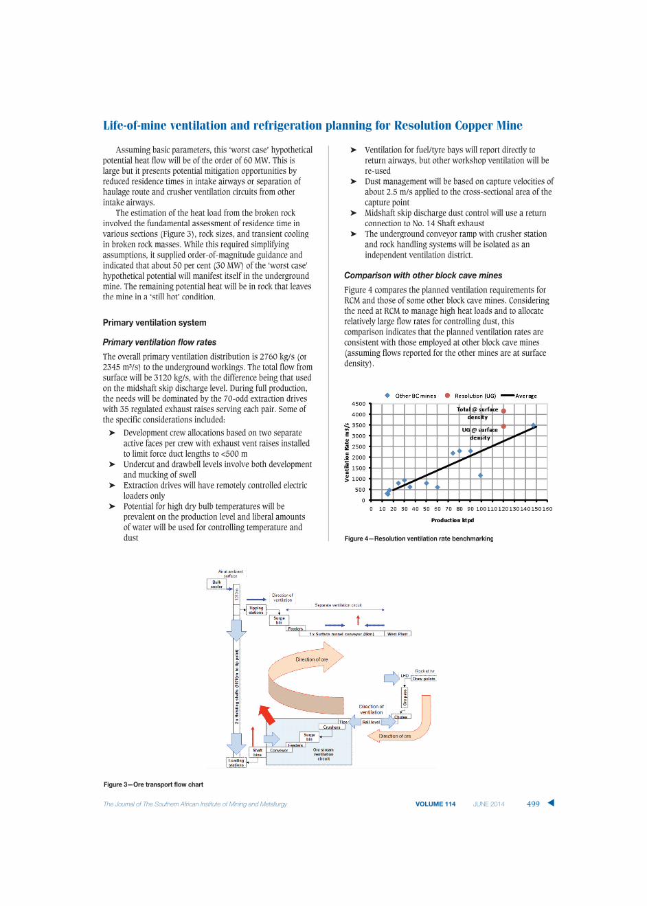
Assuming basic parameters, this ‘worst case’ hypotheticalpotential heat flow will be of the order of 60 MW. This islarge but it presents potential mitigation opportunities byreduced residence times in intake airways or separation ofhaulage route and crusher ventilation circuits from otherintake airways.
The estimation of the heat load from the broken rockinvolved the fundamental assessment of residence time invvarious sections (Figure 3), rock sizes, and transient coolingin broken rock masses. While this required simplifyingassumptions, it supplied order-of-magnitude guidance andindicated that about 50 per cent (30 MW) of the ‘worst case’hypothetical potential will manifest itself in the undergroundmine. The remaining potential heat will be in rock that leavesthe mine in a ‘still hot’ condition.
Primary ventilation system
PPrimary ventilation flow rates
The overall primary ventilation distribution is 2760 kg/s (or2345 m³/s) to the underground workings. The total flow fromsurface will be 3120 kg/s, with the difference being that usedon the midshaft skip discharge level. During full production,the needs will be dominated by the 70-odd extraction driveswwith 35 regulated exhaust raises serving each pair. Some ofthe specific considerations included:
➤ Development crew allocations based on two separateactive faces per crew with exhaust vent raises installedto limit force duct lengths to <500 m
➤ Undercut and drawbell levels involve both developmentand mucking of swell
➤ Extraction drives will have remotely controlled electricloaders only
➤ Potential for high dry bulb temperatures will beprevalent on the production level and liberal amountsof water will be used for controlling temperature anddust
➤ f fVentilation for fuel/tyre bays will report directly toreturn airways, but other workshop ventilation will bere-used
➤ Dust management will be based on capture velocities ofabout 2.5 m/s applied to the cross-sectional area of thecapture point
➤ Midshaft skip discharge dust control will use a returnconnection to No. 14 Shaft exhaust
➤ The underground conveyor ramp with crusher stationand rock handling systems will be isolated as anindependent ventilation district.
Comparison with other block cave mines
Figure 4 compares the planned ventilation requirements forRCM and those of some other block cave mines. Consideringthe need at RCM to manage high heat loads and to allocaterelatively large flow rates for controlling dust, thiscomparison indicates that the planned ventilation rates areconsistent with those employed at other block cave mines(assuming flows reported for the other mines are at surfacedensity).
Life-of-mine ventilation and refrigeration planning for Resolution Copper Mine
499The Journal of The Southern African Institute of Mining and Metallurgy VOLUME 114 JUNE 2014 ▲
Figure 3—Ore transport flow chart
Figure 4—Resolution ventilation rate benchmarking

Life-of-mine ventilation and refrigeration planning for Resolution Copper Mine
Shafts and primary ventilation infrastructure
Figure 5 shows the life-of-mine primary ventilation circuit.No. 11, No. 12, and No. 13 Shafts will downcast and No. 9,No, 10, and No. 14 Shafts will upcast together with exhaustvvia the conveyor drift.
Provision is made for a return connection between theskip discharge zone and midshaft pump station to theexhaust shafts and conveyor tunnel to surface. Thevventilation distribution in each airway, with the exception ofthe conveyor and regulated returns, is based on free splittingout of the shafts and through the workings. The returnvventilation from the mining block will join the return air fromthe ore handling system and flow in the main return systemto the upcast shafts. The underground return airways willoperate at near-limiting air velocities for occasional vehicle orpedestrian access. The main fan stations will be installed onsurface and will operate in exhaust mode. To allow forphased increase in ventilation capacity, available surfacespace during sinking, and long-term security of production, itis planned to connect all exhaust shafts together in amanifold configuration (all fans connected to all shafts).
HHigh-speed intake airways with booster fans
The primary intake infrastructure will include two largeairways (each >60 m²) that will be used as high-speeddedicated intakes. These airways will be no-go zones and willbe operated at air speeds >11 m/s, and they will carry morethan 60 per cent of all underground ventilation (below skipdischarge level). Booster fans will be installed in each of theairways with the objective of optimizing the carrying capacityof these large airways as well as controlling air velocity inother trafficable airways. Each of these fan stations will havefour fan motor sets (each 250 kW) installed in parallel.
Undercut levels
There will be two undercut levels (spaced at 20 m) in order toachieve the required wide inclined undercut for caveinitiation. The undercut levels are generally challenging fromthe ventilation perspective, and they were examined inparticular detail with stand-alone VUMA models. In the
fmodels, provision was made for dead-end swell mucking, rimtunnel and crosscut development, and cubbies for swell muckdump every 200 m.
Production level
Once steady production has been achieved, there will be up to70 open, 150 m long production crosscuts. Of these, 35production crosscuts will be active (35 electric loaders will bemucking) and 35 production crosscuts will be available foroperation. The production crosscut allocation alone is 840kg/s. The air will be distributed to open production crosscutsby regulators or secondary fans in the return raises,controlled from a central control station. This is a relativelylow air allocation and the ventilation distribution control willbe challenging. This specific VUMA model was scrutinized indetail (Figure 6).
Dust management
The management of respirable dust will be very importantbecause of the high levels of silica. The dust will have to besuppressed, captured, or report to return airways. The mainstrategy will be to direct contaminated air to return airwaysand for this, significant ventilation capacity has beenallocated. With respect to control of respirable dust, provisionwill be made for industry best-practice dust controls such as:
➤ Dedicated exhaust ventilation systems with large flows.In total, there will be 755 kg/s (25 per cent of the entireprimary ventilation) allocated to dust control direct toreturn
➤ Remote loading of extraction level with operatorlocation on the intake side
➤ Extensive use of water sprays (which will also helpcontrol high dry bulb temperature) at draw points andloading/transfer points, thus wetting broken rock to atleast 2 per cent moisture
➤ Road base maintenance and dust suppression withwater suppression sprays in all roadways for routineand controlled wetting
➤ Limited access to return airways➤ Overall layout design will minimize the need for
filtration and re-use of contaminated air. However,
▲
500 JUNE 2014 VOLUME 114 The Journal of The Southern African Institute of Mining and Metallurgy
Figure 5—Distribution of ventilation

f fsome filtration may be needed in areas remote fromreturn airways such as main conveyor transfer pointsand secondary belts
➤ Extensive use to be made of PPE and personnel will betrained in the control of exposure to respirable dust
➤ Respirable dust sampling regime will be set-up tomonitor employee exposure and samples will beanalysed for composition, including respirable freesilica in its various forms.
The following dust generation and ore transfer pointshave been accounted for: extraction level loader transport andtipping; rail loading level; rail tip to belt feeders (rail tip level,crusher level, transfer conveyor feeders); skip loading; skipdischarge, shaft-to-surface conveyor drift.
VVUMA heat load and energy balance modelling
The design snapshot scenario (Figure 2) was selected as thecritical design year for sizing the ultimate ventilation andrefrigeration needs. VUMA software was used to model thefull mine layout and to simulate the different ventilation
f fstrategies. This includes the full interactive simulation of theheat flow, ventilation, and cooling systems to determine theair temperatures, flow rates, heat loads, and coolingrequirements (Figure 7). The simulations take full account ofthe block cave mining details, and this software is unique inthat it deals with the important effects of broken rock andadvancing rock faces.
This design snapshot relates to the period when the firstpanel is approaching completion and the second panel isstarting production. Other scenarios towards the end of life-of-mine as well as the development phases were modelledseparately (but are not discussed here).
The heat load due to all the mobile equipment and staticequipment facilities was input at the relevant nodes andbranches, as was the heat flow from the broken rockdiscussed above. The models indicated that the mine heatloads will be satisfied with the following ventilationresources:
➤ Chilled ventilation downcast ex from surface3120 kg/s at 10.5°Cwb
Life-of-mine ventilation and refrigeration planning for Resolution Copper Mine
The Journal of The Southern African Institute of Mining and Metallurgy VOLUME 114 JUNE 2014 501 ▲
Figure 6—Production level temperatures (blue = 20°Cwb; red = 30°Cwb)
Figure 7—Ultimate VUMA model (blue = 20°Cwb; red = 30°Cwb)

Life-of-mine ventilation and refrigeration planning for Resolution Copper Mine
➤ fSurface bulk air cooler duty 105 MW➤ Chilled service water 50 L/s at 4°C➤ Underground secondary air coolers 35 MW
The global energy balance can be satisfied by differentcombinations of higher air flow rates with cool air or lowerair flows with colder air. The optimum is dictated by issuessuch as available downcast capacities, overall costs of thevventilation and cooling systems, standard equipmentcapacities, and phase-in needs.
Following a number of iterations that included theshaft(s) sizing, sensitivity studies (more/less undergroundrefrigeration, use of ice, etc.), the above mix of flow rate andrefrigeration capacity is considered to be close to optimum.Trade-off studies were conducted with different splitsbetween surface and underground refrigeration and themanner in which the cooling is distributed.
In summary, a significant refrigeration capacity will be onsurface. However, the underground refrigeration will beextremely important during the development phases and willprovide the essential high positional efficiency air coolersdirectly in the workings during production phases.
Description of refrigeration system
Surface refrigeration system
The surface refrigeration system will comprise:
➤ Central surface refrigeration plant room and refrig-eration machines (and thermal store)
➤ Surface bulk air coolers at each downcast shaft➤ Service water refrigeration system to provide chilled
surface water to underground.From the central plant room, chilled water will be served
to surface bulk air coolers at each of the downcast shafts. Inaddition, there will be a supplementary surface refrigerationsystem that will provide general chilled service water tounderground.
The primary refrigeration system will comprise main baseload machines prechilling water flow from the bulk aircoolers. From these plants, chilled water will then flow to thethermal storage dam containing tube banks through whichsubzero glycol is circulated. Ice will be formed on the outsideof the tubes during the colder part of the day and then meltedby the circulating water during the warm part of the day. Thechilled water will leave the thermal storage dam at temper-atures close to 0°C. The thermal storage will allow peak loaddamping and optimal energy management.
The combined plant and ice store system will provide 109MW nominal refrigeration capacity.
There will be a number of large refrigeration machinemodules chilling water and glycol. All the machines will besimilar, with interchangeable components. The refrigerationmachine modules will be factory-assembled and packagedplants with R134a centrifugal compressors and shell-and-tube evaporators/condensers. Each plant will have differingprocess conditions that will depend on final equipmentselection. However, for example, the lead water chillingplants will have a refrigeration duty of 22 MW.
Each of the downcast shafts will be served by bulk aircoolers in the form of horizontal spray heat exchangers inwwhich the air is forced through an intense spray of chilled
water in a horizontal concrete tunnel (Bluhm et al., 2001).Within the sprays, heat exchange will occur directly acrossthe large surface area of the spray drops. Where the cool airemerges from the chamber, mist eliminators will be installedto ensure that no water is carried out. For example, the No.13 Shaft bulk air cooler will have a cooling duty of 40 MW.
Chilled service water will be a very important part of theunderground cooling. The chilled service water will be usedfor dust control, localized cooling sprays, and mine serviceneeds and will provide effective localized cooling wherever itis applied. Thus, on surface, in addition to the main refrig-eration system, there will be a separate independent surfacerefrigeration system that will provide general chilled servicewater to all the underground workings.
Underground refrigeration system
The underground refrigeration system will comprise two maincomponents:
➤ Centralized underground refrigeration plant chamberand refrigeration machines
➤ Suite of underground air coolers and cold water distri-bution system.
There will be a single central underground refrigerationplant chamber located near the mining block off the exhaustvent level. The return ventilation system will be used for heatrejection from the refrigeration plant. The refrigerationmachines will provide cold water, in an insulated closedcircuit network, to air coolers situated strategicallythroughout the workings.
The required secondary air cooler overall duty will be35 MW and the underground refrigeration plant will provide40 MW capacity to overcome losses.
The refrigeration installation will ultimately have five8 MW machines operating (plus one standby). The machineswill operate in parallel and this arrangement will allow thesystem to adjust to changes in demand. The machines willuse refrigerant R134a and will include high-speed,multistage, centrifugal compressors. The refrigerationmachines will be identical packaged units with compressormotor sets and shell and tube evaporators/condensers.
The plant room layout includes two machine rooms withthe chilled water pumps and condenser water pumps groupedin common pump chambers adjacent to their respective dams.Rejected heat will be in cooling towers in the form of sprayfilled vertical excavations rejecting heat into the returnventilation. The refrigeration plant will be adjacent to twolarge main return airways and a large part of the return flowwill be directed to the cooling towers.
For the ultimate life-of-mine scenarios, there will benumerous underground secondary air coolers with dutiesranging from 0.5-3 MW, with a total duty of 35 MW. Thesesecondary air coolers will be in the form of closed-circuitcooling coils. The main chilled water piping will comprise a500 mm insulated system near the plants, reducing as thenetwork splits up to ultimately 150 mm insulated pipesections.
Conclusion
Resolution will be a deep, hot, block cave operation with120 kt/day production. The rock will have a high silica
▲
502 JUNE 2014 VOLUME 114 The Journal of The Southern African Institute of Mining and Metallurgy
content and the mine will be deep in hot virgin rocktemperature. Thus dust issues and thermal issues dominatethe design evaluations.
The mine will employ three hoisting and service shaftsand three upcast shafts, and the total primary ventilationcapacity will be about 3000 m³/s. The general approach todust management will be to direct contaminated air to return,and some 25 per cent of the total primary air flow will beallocated in this manner. The primary intake system willinclude two large airways which will be used as high-speeddedicated intakes with booster fans. These airways will beno-go zones operating at high air speeds and will carry morethan 60 per cent of all underground ventilation.
VUMA software was used to model the full mine layoutand simulated different ventilation and refrigerationstrategies. The simulation uses an iterative process todetermine heat loads and cooling needs as well as the sizingand positioning of refrigeration system components. Thelarge heat load components were the broken rock flow,surrounding rock conduction and mobile and staticequipment facilities. The refrigeration systems will include105 MW surface bulk air cooler duty and 35 MWunderground secondary air cooler duty.
This will be a very challenging mine to ventilate and cool,but this work has demonstrated that it will be technicallyachievable with the application of existing technology.
AAcknowledgement
Permission from Rio Tinto RCM to present this paper isgratefully acknowledged.
RefserencesBLUHM, S., FUNNELL, R., and SMIT, H. 2001. Horizontal spray chambers for
surface bulk air cooling. Proceedings of the Seventh International MineVentilation Congress, Cracow, Poland.
fISO. 2004. Standard 7933, Ergonomics of the thermal environment – analyticaldetermination and interpretation of heat stress using calculation of thepredicted heat strain. 2nd edn. Geneva.
NATIONAL INSTITUTE OF OCCUPATIONAL SAFETY AND HEALTH (NIOSH). 2002. NIOSHHazard Review, Health effects of Occupational Exposure to RespirableCrystalline Silica. Atlanta, GA.
NATIONAL INSTITUTE OF OCCUPATIONAL SAFETY AND HEALTH (NIOSH), 2011. DieselAerosols and Gases in Underground Mines: Guideto Exposure Assessmentand Control. (eds.) Bugarski, A.D., Janisko, S.J., Cauda, E.G., Noll, J.D.,and, Mischler, S.E. Report of Investigations 9687. Atlanta, GA.
NATIONAL TOXICOLOGY PROGRAM (NTP). 2003. Silica Crystaline (Respirable Size),US National Toxicology Program. US Department of Health and HumanServices, Research Triangle Park, NC.
PASCOE, C., ODDIE, M., and EDGAR, I. 2008. Panel caving at the Resolutioncopperproject. Proceedings of the Fifth International Conference and Exhibitionon Mass Mining, Lulea, Sweden.gg ◆
Life-of-mine ventilation and refrigeration planning for Resolution Copper Mine
The Journal of The Southern African Institute of Mining and Metallurgy VOLUME 114 JUNE 2014 503 ▲
AusIMM President Geoff Sharrock FAusIMM(CP) presenting the 2014AusIMM Best Paper prize to Steven Bluhm in Cape Town