Short Notes on Carbon Cycle, Nitrogen Cycle and Sulphur Cycle
Advanced Steel Construction Vol. 11, No. 3, pp. 395-410 (2015) 395
LIFE-CYCLE COST BASED MAINTENANCE AND REHABILITATION STRATEGIES FOR CABLE SUPPORTED
BRIDGES
Chun-sheng Wang 1,*, Mu-sai Zhai1, Hai-ting Li 1, Yi-qing Ni 2 and Tong Guo 3
1 Engineering Research Center for Large Highway Structure Safety of Ministry of Education, College of Highways,
Chang'an University, Xi'an, Shaanxi Province, China 2 Department of Civil and Environmental Engineering, The Hong Kong Polytechnic University,
Hong Kong, China 3 Key Laboratory of Concrete and Prestressed Concrete Structures of the Ministry of Education, Southeast University,
Nanjing, China *(Corresponding author: E-mail: [email protected])
ABSTRACT: Initial cost was mainly considered in constructing a bridge in the past, whereas future payments such as the cost of strengthening or rehabilitation were neglected. This situation has brought numerous economic as well as social problems due to the lack of rational maintenance and rehabilitation strategies. Thus, it is necessary and urgent to develop appropriate bridge maintenance and rehabilitation strategies that not only meet serviceability criteria but also consider the life-cycle cost (LCC) optimization. This paper discusses major hazards of in-service cable supported bridges, including fatigue cracking of orthotropic steel decks, deterioration of cables, damage of main cables, hangers and expansion joints et al. Advanced maintenance and rehabilitation tools are introduced to save the life-cycle cost, acoustic emission monitoring technique and cold retrofit technique are detailed studied. A framework is provided for the strategies of maintenance and rehabilitation based on life-cycle cost. The framework takes into account of the safety, serviceability and sustainability during the lifetime of cable supported bridges. Keywords: Cable supported bridge, Fatigue and fracture, Durability, Life-cycle cost, Maintenance and rehabilitation, Cold retrofit technique, Sustainability DOI:10.18057/IJASC.2015.11.3.12
1. INTRODUCTION Cable supported bridges, namely suspension bridges and cable-stayed bridges are important structures to the highway and railway infrastructures as they usually cross major rivers and act as critical links between highly habited zones [1]. In recent years, bridge engineering in China has progressed significantly and achieved marvellous success [2-3]. The design and construction of cable supported bridges has progressed considerably in China since 1980s. Main span lengths of the cable supported bridges were less than 300m in the 1980s and reached over 1000m in the 21st century. For example, Sutong cable-stayed bridge has a main span length of 1088m, and the Xihoumen suspension bridge has a main span length of 1650m. Tables 1 and 2 show the major suspension bridges and cable-stayed bridges constructed in China in the late 20th century, respectively. Cable supported bridges in China are relatively new and are still in an early stage of their expected service life. Some major hazards have been observed especially in those constructed in the 20th century. The maintenance and rehabilitation of these bridges are of great importance. During a period of about 15 years, thirteen suspension bridges and twenty-two cable-stayed bridges with mains span over 400m were constructed across China [4]. The conditions of these bridges have begun to deteriorate and various damages continuously accumulate during their service life. Cable supported bridges may experience poor performance or even collapse much earlier than expected in their service life if no sound maintenance and rehabilitation strategies are taken place.

396 Life-Cycle Cost Based Maintenance and Rehabilitation Strategies for Cable Supported Bridges
Problems mainly include fatigue failure of the orthotropic steel deck, fracture or deterioration of main cables and hangers, as well as wear and damage of expansion joints, due to wheel loading, harsh environments and natural hazards. Besides, as the traffic needs for them are very large in most cases, consequences of their closure or even traffic capacity reduction may lead to inconvenience for users and thus result in significant losses of society and economy. Therefore, sound maintenance and rehabilitation strategies for cable supported bridges are important for the purpose of providing an acceptable standard of safety and serviceability, as well as meeting the sustainability and low carbon energy requirements during their operation service time.
Table 1. Suspension Bridges Constructed in China in the Late 20th Century
No. The Name of Bridge Constructed
Year Main Span Length
(m) 1 Sichuan Hanyuan Bridge 1982 208 2 Tibet Dazi Bridge 1984 500 3 Fujian Taining Bridge 1989 284 4 Sichuan Fengjie Bridge 1990 205 5 Shantou Bay Bridge 1995 452 6 Hubei Xiling Bridge 1996 900 7 Guangdong Humen Bridge 1997 888 8 Hongkong Tsingma Bridge 1997 1377 9 Sichuan Fengdu Bridge 1997 450 10 Xiamen Haicang Bridge 1999 648 11 Jiangsu Jiangyin Bridge 1999 1385
Table 2. Cable-stayed Bridges Constructed in China in the Late 20th century
No. The Name of Bridge Constructed
Year Main Span Length
(m) 1 Guangzhou Haiyin Bridge 1988 175 2 Shanghai Nanpu Bridge 1991 423 3 Shanghai Yangpu Bridge 1993 602 4 Hubei Yunyan Bridge 1993 414 5 Wuhan Erqiao Bridge 1995 400 6 Anhui Tongling Bridge 1995 432 7 Chongqing Lijiatuo Bridge 1996 444
8 Hongkong Kap Shui Mun
Bridge Bridge 1997 430
9 Shanghai Xupu Bridge 1997 590 10 Hongkong Tingkau Bridge 1998 475 11 Fujian Queshi Bridge 1999 518
During the past few decades, more and more engineers, researchers and managers have recognized that low tender prices usually may not lead to low lifetime costs and thereby the concept of life-cycle cost (LCC) of civil infrastructures have been widely adopted. Researchers and owners are more and more oriented to the promotion of sustainability as well as achieving the goal of life-cycle performance optimization with respect to the economic, environmental and social demands. As defined by the United States Department of Transportation that, life-cycle cost assessment (LCCA) is an evaluation technique which insists life-cycle cost optimization. It has been more and more widely used by the transportation agencies for new bridge construction projects as well as in-service bridge maintenance and rehabilitation.

Chun-sheng Wang, Mu-sai Zhai, Hai-ting Li, Yi-qing Ni and Tong Guo 397
In 1995, Mohammadi identified some key factors affecting the LCC of bridges [5]. They also proposed an optimized method for making rational decisions in scheduling the time and selecting candidate bridge components. Frangopol and his team [6-12] have discussed the past, present, and future of life-cycle design, inspection, assessment, rehabilitation and management of bridge structures. They also did research about optimum maintenance strategies and indicated that additional research works are required to develop a better life-cycle model. In addition, they also announced that tools to quantify risks, costs as well as benefits associated with bridges are needed. In order to ensure an adequate level of reliability at a minimal LCC, two maintenance models known as the Rijkswaterstaat’s model and the Frangopol’s model for deteriorating civil infrastructures were described and compared in 2006. Many studies were made about the life-cycle cost analysis, design, evaluation, rehabilitation, management, and maintenance of civil infrastructure system. However, the study of cable supported bridge maintenance and rehabilitation based on life-cycle cost is limited. It is necessary and urgent to develop appropriate maintenance and rehabilitation strategies that not only meet serviceability criteria but also consider the life-cycle cost optimization. 2. MAJOR HAZARDS OF CABLE SUPPORTED BRIDGES 2.1 Fatigue Cracking of Orthotropic Steel Decks Orthotropic steel decks (OSDs) have been widely used in cable supported bridges for several decades in parts of the world for they are considerably lighter, thus allow longer spans to be efficiently designed [13]. Although the technology was developed in the 1970s, the use of OSDs in China began relatively late compared to US, Europe and Japan. Many long span cable supported bridges in China have adopted OSDs recently, such as Guangdong Humen Bridge, Xiamen Haicang Bridge, Nanjing Yangzi River Second Bridge, Jiangsu Jiangyin Yangzi River Bridge and Jiangsu Sutong Yangzi River Bridge. To date, there are about 30 cable supported bridges using orthotropic steel decks with main spans over 400m in China. The longest of these is the 1650-meter Zhoushan Xihoumen Suspension Bridge, which was opened to traffic in 2009 [2, 4]. The complex configurations and direct exposure to repeated vehicular loading lead to relatively high levels of stress concentration. Many details of OSDs are fatigue-sensitive. Recently, more and more engineers, researchers, as well as bridge owners pay more attention to the fatigue problem of the OSDs since a large number of fatigue cracks have been found [14]. As shown in Figure 1[15], hundreds of fatigue cracks have been detected in the steel decks of the 888-meter long box girder of Guangdong Humen Bridge just ten years after opening to traffic.
Figure 1. Cracking in Deck Plates and Along Fillet-welds Between Ribs and Deck Plates
In OSDs, details such as cut-outs in diaphragms, rib-to-diaphragm and rib-to-deck joints are susceptible to fatigue failure [16]. A complex combination of in-plane and out-of-plane stress may happen due to the distortion of diaphragm and web of rib under the action of repeated vehicular loading. Besides, as closed stiffening ribs can only be welded from the outside, the quality of such
398 Life-Cycle Cost Based Maintenance and Rehabilitation Strategies for Cable Supported Bridges
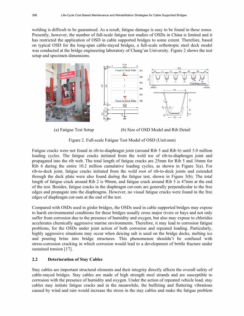
welding is difficult to be guaranteed. As a result, fatigue damage is easy to be found in these zones. Presently, however, the number of full-scale fatigue test studies of OSDs in China is limited and it has restricted the application of OSD in cable supported bridges to some extent. Therefore, based on typical OSD for the long-span cable-stayed bridges, a full-scale orthotropic steel deck model was conducted at the bridge engineering laboratory of Chang’an University. Figure 2 shows the test setup and specimen dimensions.
(a) Fatigue Test Setup (b) Size of OSD Model and Rib Detail
Figure 2. Full-scale Fatigue Test Model of OSD (Unit:mm) Fatigue cracks were not found in rib-to-diaphragm joint (around Rib 5 and Rib 6) until 5.0 million loading cycles. The fatigue cracks initiated from the weld toe of rib-to-diaphragm joint and propagated into the rib web. The total length of fatigue cracks are 25mm for Rib 5 and 16mm for Rib 6 during the entire 10.2 million cumulative loading cycles, as shown in Figure 3(a). For rib-to-deck joint, fatigue cracks initiated from the weld root of rib-to-deck joints and extended through the deck plate were also found during the fatigue test, shown in Figure 3(b). The total length of fatigue crack around Rib 2 is 90mm, and fatigue crack around Rib 5 is 47mm at the end of the test. Besides, fatigue cracks in the diaphragm cut-outs are generally perpendicular to the free edges and propagate into the diaphragms. However, no visual fatigue cracks were found in the free edges of diaphragm cut-outs at the end of the test. Compared with OSDs used in girder bridges, the OSDs used in cable supported bridges may expose to harsh environmental conditions for these bridges usually cross major rivers or bays and not only suffer from corrosion due to the presence of humidity and oxygen, but also may expose to chlorides accelerates chemically aggressive marine environments. Therefore, it may lead to corrosion fatigue problems, for the OSDs under joint action of both corrosion and repeated loading. Particularly, highly aggressive situations may occur when deicing salt is used on the bridge decks, melting ice and pouring brine into bridge structures. This phenomenon shouldn’t be confused with stress-corrosion cracking in which corrosion would lead to a development of brittle fracture under sustained tension [17]. 2.2 Deterioration of Stay Cables Stay cables are important structural elements and their integrity directly affects the overall safety of cable-stayed bridges. Stay cables are made of high strength steel strands and are susceptible to corrosion with the presence of humidity and oxygen. Under the action of repeated vehicle load, stay cables may initiate fatigue cracks and in the meanwhile, the buffeting and fluttering vibrations caused by wind and rain would increase the stress in the stay cables and make the fatigue problem

Chun-sheng Wang, Mu-sai Zhai, Hai-ting Li, Yi-qing Ni and Tong Guo 399
worse. This may destroy the protection system of stay cables and accelerate the corrosion process as shown in Figure 4[18].
(a) Typical Cracks in Rib-to-diaphragm Joints
(b) Typical Cracks in Deck Plate
Figure 3. Typical Fatigue Cracks Observed During Orthotropic Steel Deck Test
Deterioration of stay cables mainly refers to damage in the cover, corrosion of steel wires, fatigue of cable and cable anchor systems, and other damages caused by excessive vibration. The corrosion of stay cables includes uniform corrosion, dent corrosion, crack corrosion, stress corrosion and corrosion fatigue. Anti-corrosion measures should be made on a case-by-case basis since each bridge is different in production, transportation, storage, erection and maintenance. Commonly used PE protective cover of stay cables may deteriorate due to damages such as transverse cracks, longitudinal cracks, scratches, corrugations and indentations. After these, corrosion of the steel wire may accelerate. In addition, the actions of wind and rain, or the vibration of the bridge tower and deck, vibrations such as wake galloping, vortex-induced vibration, rain vibration, parametric-induced vibration as well as buffeting may occur. Some of these vibrations’ amplitudes are not big, but the frequency is relatively larger while others amplitudes may be big, but the occurrence is relatively low. Such vibrations of the stay cables are the main cause of fatigue in the vicinity of the anchorages of cable-stayed bridges and may also damage the corrosion protection system of cables or even lead to the failure of stay cables.
Figure 4. Corrosion of Stay Cables[18]

400 Life-Cycle Cost Based Maintenance and Rehabilitation Strategies for Cable Supported Bridges
2.3 Damage of Main Cables and Hangers The main cables and hangers are essential elements of a suspension bridge and in the meanwhile, they are also the most difficult components to maintain [19]. Thus, more attention should be paid to their maintenance and rehabilitation. Besides, a main cable’s damage has always been associated with corrosion and the damage of hangers has always been associated with corrosion or vibrations such as buffeting, galloping and rain vibration or a combination of these [20]. Similarly to orthotropic steel decks and stay cables, the main cables and hangers of suspension bridges sometimes are exposed to harsh environmental conditions for the bridges located in chemically aggressive marine environments. Substances such as chlorides, oxygen and so on would eventually percolate into the gaps of the main cables and hangers through rain and water, which may lead to the corrosion of the steel strands. Figure 5 shows the details of corroded steel strands [21].
Figure 5. Details of Corroded Steel Strands [21] 2.4 Damage of Expansion Joints As the temperature changes, the girder of cable supported bridges will experience expansion and contraction which may lead to longitudinal strain in the girder. In the meanwhile, the bridge deck will produce longitudinal displacements under vehicle loads. In order to meet the requirements of such strain and deformation, it is necessary to set expansion joints between the bridge girder and the abutment or between hinged joints. As expansion joints are repeatedly subjected to vehicle loads, even a very small unevenness can cause a great impact. Expansion joints have been recognized as weak components in cable supported bridges for a long time. In addition, along with the rapid increase of traffic volume and the unavoidable phenomenon of overload, the impact of expansion joints increases. This may accelerate the wear and damage of expansion joints and cause both economic and social problems in maintenance and rehabilitation during the operation service time. Sørensen concluded that during the operation service life [20], compared with other maintenance, rehabilitation and replacement cost, the cost for movement elements such as expansion joints is usually a major expense. 3. ADVANCED TOOLS FOR MAINTAINENCE AND REHABILITATION 3.1 Acoustic Emission Technique The acoustic emission (AE) technique is a non-destructive testing tool for real time monitoring of material damages. It has been widely used in aerospace, machine manufacturing pipelines, and many other fields. In bridge engineering, AE technique has been used to monitor concrete cracks
Chun-sheng Wang, Mu-sai Zhai, Hai-ting Li, Yi-qing Ni and Tong Guo 401
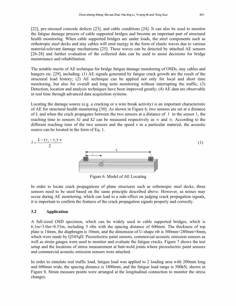
[22], pre-stressed concrete defects [23], and cable conditions [24]. It can also be used to monitor the fatigue damage process of cable supported bridges and become an important part of structural health monitoring. When cable supported bridges are under loads, the steel components such as orthotropic steel decks and stay cables will emit energy in the form of elastic waves due to various material-relevant damage mechanisms [25]. These waves can be detected by attached AE sensors [26-28] and further evaluation of the collected data can be used to assist decisions for bridge maintenance and rehabilitation. The notable merits of AE technique for bridge fatigue damage monitoring of OSDs, stay cables and hangers etc. [29], including: (1) AE signals generated by fatigue crack growth are the result of the structural load history; (2) AE technique can be applied not only for local and short time monitoring, but also for overall and long term monitoring without interrupting the traffic; (3) Detection, location and analysis techniques have been improved greatly; (4) AE data are observable in real time through advanced data acquisition systems. Locating the damage source (e.g. a cracking or a wire break activity) is an important characteristic of AE for structural health monitoring [30]. As shown in Figure 6, two sensors are set at a distance of L and when the crack propagates between the two sensors at a distance of l to the sensor 1, the reaching time to sensors S1 and S2 can be measured respectively as 1 and 2. According to the different reaching time of the two sensors and the speed v in a particular material, the acoustic source can be located in the form of Eq. 1.
2 1( )
2
L vl
(1)
Figure 6. Model of AE Locating
In order to locate crack propagations of plane structures such as orthotropic steel decks, three sensors need to be used based on the same principle described above. However, as noises may occur during AE monitoring, which can lead to a side-effect on judging crack propagation signals, it is important to confirm the features of the crack propagation signals properly and correctly. 3.2 Application A full-sized OSD specimen, which can be widely used in cable supported bridges, which is 6.1m×3.0m×0.53m, including 5 ribs with the spacing distance of 600mm. The thickness of top plate is 14mm, the diaphragm is 10mm, and the dimension of U-shape rib is 300mm×280mm×8mm, which were made by Q345qD. Piezoelectric paint sensors, commercial acoustic emission sensors as well as strain gauges were used to monitor and evaluate the fatigue cracks. Figure 7 shows the test setup and the locations of stress measurement at butt-weld joints where piezoelectric paint sensors and commercial acoustic emission sensors were attached. In order to simulate real traffic load, fatigue load was applied to 2 loading area with 200mm long and 600mm wide, the spacing distance is 1800mm, and the fatigue load range is 300kN, shown in Figure 8. Strain measure points were arranged at the longitudinal connection to monitor the stress changes.

402 Life-Cycle Cost Based Maintenance and Rehabilitation Strategies for Cable Supported Bridges
(a) Test Setup (b) Strain Gage and Piezoelectric Paint Sensor (c) Commercial AE Sensors
Figure 7. Laboratory Test Set-up and AE Sensor Placement
The circular shaped piezoelectric paint sensors, see Figure 7(b), have a diameter of 12 mm and a thickness of 0.5 mm as with a 42% volume fraction of PZT-5A. The stress monitoring results showed that the stress range at the bottom butt-welds of Rib 5 was around 70 MPa under fatigue load range of 300 kN before 2 million load cycles. From 2 to 3 million cycles, the stress range reduced from 70 MPa to 60 MPa, which indicated fatigue crack initiation and propagation. From 3 to 3.4 million cycles, the stress range decreased at a very fast rate and several long cracks were found at bottom butt-welds of Rib 5. In order to evaluate the performance of piezoelectric paint sensor in detecting AE events associated with fatigue crack initiation and propagation, the commercial AE sensors supplied by Physical Acoustics Company (PAC) and attached to the specimen with vacuum grease and held in place with plastic clamps were installed at the same zones after 3 million load cycles, as shown in Figure 7(c). In this experimental fatigue research, the piezoelectric paint sensors were connected to a custom-designed signal conditioning circuit comprised of preamplifier with low pass and high pass filters. The amplifier voltage gain was set as 40 dB, while the bandwidth of band pass filter was from 5 to 600 kHz. AE data were processed and displayed through a DISP-16 outdoor acquisition work station manufactured by Physical Acoustics Company. To minimize extraneous noise while allowing for the record of genuine AE signals, the threshold of each AE channel was set as 45 dB. To assure the condition of each sensor and the locating capability of the sensors arrangement, pencil lead break (PLB) tests were conducted before testing. Several types of AE signal waveforms were collected by the commercial AE sensors, as shown in Figure 8. The waveform shown in Figure 8(a) is a typical AE waveform for a fatigue crack activity, with shorter rise time, lower counts and higher peak amplitude. In Figure 8(b), the waveform reflects emissions during friction activities. Figure 8(c) is from a PLB test, where the signal rapidly attains the peak amplitude and then fades gradually. These representative waveforms can be used as references to distinguish noise data from the AE signals caused by crack growth.
(a)Crack Growth AE Waveform (b) Waveform Induced by Friction (c) Waveform Induced by PLB
Figure 8. AE Waveforms Reference from Crack Growth, Friction and PLB Tests

Chun-sheng Wang, Mu-sai Zhai, Hai-ting Li, Yi-qing Ni and Tong Guo 403
Figure 9 shows that the AE signals are concentrated among three sensors one day after three long cracks were found at the bottom butt-welds of Rib 5. Comparing the locating graph with the AE sensors arrangement at the bottom butt-welds of Rib 5 as shown in Figure 7(c), two crack tips at the zone were found where AE signals were concentrated. Consequently, conclusion is drawn that AE signals are related to the existing crack growth activity.
Figure 9. An AE Monitoring Locating Graph
3.3 Cold Retrofit techniques for OSDs Fatigue cracking is a worldwide engineering problem of orthotropic steel deck (OSD), which affects the service safety and duration of the bridge structures. Since OSD is commonly used modern long span bridges, how to retrofit the fatigue cracks plays an important role in maintenance and rehabilitation for cable supported bridges. According to amount of in-site inspection results and experimental study results, stress levels of typical fatigue details in OSDs are relatively higher due to the thin deck plate, complex configuration and low construction quality. Researchers have tried a lot to find new ways to decrease the stress level, together with the goals to meet the durability and economy demands. Wang proposed concrete composite layer bonding to OSD system by stud welded on the deck system, which was applied to a real steel bridge [31]. Based on the loading test, the stress level of fatigue details is obviously lower compared to other similar bridge. Shao developed an innovative composite bridge deck system with thin reactive powder concrete (RPC) on orthotropic steel plate [32]. Static experiment result shows that tensile stresses in steel deck decrease obviously when the innovative steel-RPC composite deck system is adopted and the maximum reducing amplitude is over 70%.
(a) Concrete Composite Layer (b) RPC Composite Layer (c) UHPFRC Composite Layer
Figure 10. Different Composite Layer for OSDs

404 Life-Cycle Cost Based Maintenance and Rehabilitation Strategies for Cable Supported Bridges
In recent years, Ultra high performance fibre reinforced concrete (UHPFRC) have caught engineers’ eyes, which is made of silica fume, fly ash, steel fibre instead of coarse aggregates. Researchers have conducted a series of experiments to study the material performance, mechanical performance and the strengthening effect by UHPFRC. In this paper, UHPFRC composite layer is proposed to take place of traditional pavement, ordinary concrete composite layer and RPC composite layer. For the advantages of higher strength and better durability, the thickness of UHPFRC composite layer decreases to 40mm from the 80mm for ordinary concrete and 50mm for RPC (Figure 10). Since welding stud or steel bar as shear connector will bring new fatigue details, cold connecting techniques by high strength adhesive is introduced to connect the composite layer with OSD system.
Composite layer can be not only used in design stage, but also it can be used to maintenance stage. However, the traffic will be suspended when using composite layer to replace old pavement system, which will bring negative social influence and economy loss. Therefore, some researchers tried other means to strengthen the local areas according to the structural characteristic of OSDs. Kolstein installed stop hole on the fatigue crack hole, and bolted steel plate on the cracking region by the high tensile bolts [33]. Tabata developed an innovative method of retrofit OSD without the need for traffic restriction to eliminate fatigue cracks originating from the weld between the deck plate and U-shaped rib [34]. At present, retrofit method for orthotropic steel bridge deck mainly concentrate on mechanical repair or hot repair, the construction process is complex and is easy to bring new damage to the structure. In order to develop generally innovative retrofit method, cold maintenance concept is proposed, i.e. adopting cold connecting plate to strengthen the fatigue region. Compared with the traditional maintenance method, cold retrofit methods can enhance the local rigidity to prevent crack further propagation without any secondary damage. Cold connecting method includes high strength structural adhesive, bolting and self-tapping screw, plate can adopt steel plate, shape steel, sandwich plate system or carbon fibre plate. According to the characteristics of fatigue cracking region, different connecting method and different plate material can be used together for hybrid strengthening (Figure 11).
(a) Bonding Steel Plate (b) Composite Connecting Angle Steel
Figure 11. Cold Retrofit Method for OSDs In order to study cold retrofit method feasibility, a full-scale orthotropic steel bridge deck fatigue test was conducted, the test setup shown in Figure 7. When the loading cycles accumulated to 3 million, the stress of measure point around rib 5 connection decreased, 3 cracks were observed after another 280 thousand cycles. Cold bonding steel plate method was applied to strengthen the fatigue cracking area, the dimension of steel plate is 3400mm×180mm×10mm based on the finite element analysis result (shown in Figure 12). After retrofit, strain gages were arranged on the steel plate corresponding to the gages on the ribs. With the loading cycles accumulating, stress level of longitudinal connection stayed a relatively low level, shown in Figure 13. When loading cycles reached 5.12 million, no crack propagation was observed, and the test was stopped. The test result shows that bonding steel plate can effectively prevent crack propagation, and the fatigue life can be prolonged for 75%.

Chun-sheng Wang, Mu-sai Zhai, Hai-ting Li, Yi-qing Ni and Tong Guo 405
0 1 2 3 4 5 6
-20
0
20
40
60
80
100
120
140
160
Str
ess
(MP
a)
Cycles (Million)
B-RL101 B-RL201 B-RL301 B-RL401 B-RL501/GR501
Figure 12. Strengthened by Bonding Steel Plate Figure 13. Stress Change Curves
A cable-stayed bridge with steel box girder was taken into study, the span layout is 100m+160m+318m. The steel box girder is comprised of top plate, U-shape stiffener, web, diaphragm and bottom plate, total width of the box girder is 37.1m, including 6 vehicle lanes with 2 hard shoulders. The thickness of top plate is 14mm, the bottom plate is 12mm, and the web and diaphragm are both 10mm. The dimension of U-shape rib is 300mm×280mm×8mm with the center distance is 600mm, and the diaphragm standard spacing is 3750mm, shown in Figure 14. Many fatigue cracks were detected on the orthotropic steel bridge deck after less than 10 years open to traffic, and the cracks are mainly initiated from the rib-to-diaphragm joint and free edges of cutout, shown in Figure 15. According to the characteristics of fatigue crack and cracking position, bonding equal angle steel of Q345 with high strength structural adhesive was adopted to retrofit the orthotropic steel bridge decks. The angle steel dimension was 140mm×140mm×14mm with the length of 220mm.
2%
Hard Shoulder Lane 1 Lane 2 Lane 3
3500
6000 1255018550
Figure 14. Cross Section of Steel Box Girder (Unit: mm) Figure 15. Typical Fatigue Crack
Figure 16. Bonding Angle Steel Retrofit Method Figure 17. Stress Comparison
In order to determine the cold retrofit effect, several retrofit regions were selected to conduct loading test and dynamic monitoring before and after retrofit. Strain gages were arranged at the crack tip and other typical fatigue details. A 4-axle full truck was chosen to loading the test regions, shown in Figure 16. The axle distances are 1300 mm, 4500 mm and 1800 mm, the axle weights are
0 1 2 3 4 5 6
-10
0
10
20
30
40
50
60
70
39.5
66.3 X
X
Stre
ss (
MP
a)
Time(s)
Before Retrofit After Retrofit

406 Life-Cycle Cost Based Maintenance and Rehabilitation Strategies for Cable Supported Bridges
30kN, 80kN, 115kN and 115kN. Stress changes of measure point at crack tip were analyzed to assess the cold retrofit effect, shown in Figure 17. Take measure point C1105 as example, before cold retrofit the peak stress reached 66.3MPa, while the peak stress decreased to 39.5MPa after cold retrofit, the decrease rate was up to 40 percent. 3.4 Dehumidification System Steel corrosion is a recognized cause for deterioration in bridge cables and girders. There were several cases worldwide where rehabilitation and replacement had to be done due to corrosion problems and these led to enormous costs of bridge maintenance [35]. Traditional anti-corrosion protection systems for components such as main cables and steel girder cannot totally prevent corrosion, but merely slow it down. The invention and application of dehumidification systems have proven to be able to totally prevent corrosion. Generally, dehumidification systems can be designed and installed in components such as main cable, cables saddles and anchor houses of suspension bridges, stay cables of cable-stayed bridges and also steel girders. Moreover, some results of life-cycle cost analysis indicated that installing a dehumidification system may be much more economical than a traditional anti-corrosion system. This may inspire engineers in China when they are dealing with the maintenance of in-service cable supported bridges. 4. LIFE-CYCLE COST BASED MAINTAINENCE AND REHABILITATION STRATEGIES FOR CABLE SUPPORTED BRIDGES 4.1 Life-cycle Cost for Maintenance and Rehabilitation As life-cycle costs depend on lots of quantitative data rather than some qualitative information, objective and quantitative data should be selected and collected. The life-cycle cost of cable supported bridges should include costs associated with design, construction, management, inspection, maintenance and rehabilitation during the entire service life. All the components and elements that comprise the structure should be taken into consideration when dealing with life-cycle cost optimization. The cost of maintenance and rehabilitation depends on the reliability level for when the maintenance and rehabilitation work is to be applied. Thus, formulating a reasonable reliability level after maintenance and rehabilitation is important to provide an acceptable level of safety and serviceability during operation service over the entire life cycle. As maintenance and rehabilitation may lead to traffic controls or even closures, inconvenience for the users and the loss of bridge owners should also be concerned when optimizing the life-cycle cost. In addition, before starting rehabilitation, inspections and investigations should be carried out to determine the cause of the damages. The cost of inspections and investigations should also be included. During rehabilitation, it is important to focus on the prevention of traffic interruptions as LCC includes the costs of traffic delays and service time reductions. Besides, as some old cable supported bridges do not have sufficient maintenance access facilities, rehabilitation works are ideal opportunities to upgrade such facilities and in this way, future maintenance cost, which is a part of LCC, will decrease. Refer to Kong & Frangopol’s [10] analysis, the cost of maintenance for cable supported bridges during the service time is suggested to be computed as follows:

Chun-sheng Wang, Mu-sai Zhai, Hai-ting Li, Yi-qing Ni and Tong Guo 407
1
M 01 11
, ,
1
nN nT i i i ii ik ijt
i jk
f t t tCost g t dt r
v
(2)
Where , ,i i it t t are the deterioration rates of reliability depending on the type of the
applied maintenance action, reliability index profile and reliability index change of element i, due to the applied maintenance action; ig t is the probability-density function of element i and T is
the end service time; ij is the factor concern about the cost caused by traffic control, inspections
etc. and ikr are the related coefficient factors; if is the cost function and v is the discount rate of
money; N is the number of all the elements which need to be maintained. The cost for rehabilitation can also be computed similarly based on the same method and the rehabilitation strategies for cable supported bridges should also consider such factors. 4.2 Framework of Life-cycle Based Maintenance and Rehabilitation Strategy A sound life-cycle based maintenance and rehabilitation strategy for cable supported bridges should concern not only the performance of all the components that comprise the whole structure, but also the life-cycle cost, which is made of economic cost (i.e. project design cost, construction cost, monitoring cost, assessment cost, inspection cost, material cost etc.), social cost (i.e. traffic interrupt cost, convenient cost, comfortable cost, user delay cost, reputation cost etc.) and environmental cost. In order to optimize the life-cycle costs during the whole service time as well as considering the safety, serviceability, reliability and sustainability of the cable supported bridges, a preliminary framework of life-cycle based maintenance and rehabilitation strategy is proposed in Figure 18.
Figure 18. Preliminary Framework of Life-cycle Based Maintenance and Rehabilitation Strategy

408 Life-Cycle Cost Based Maintenance and Rehabilitation Strategies for Cable Supported Bridges
5. SUMMARY Recently, some cable supported bridges have experienced various performance problems or even collapse much earlier than expected in their service life. Maintenance and rehabilitation are necessary to maintain the safety, serviceability and sustainability of these bridge structures. In order to optimize maintenance and rehabilitation interventions and achieve a cost-effective life-cycle performance for in-service cable supported bridges, it is necessary and urgent to establish sound life-cycle based maintenance and rehabilitation strategies. Major hazards of in-service cable supported bridges, including fatigue cracking of orthotropic steel decks, deterioration of cables, damage of main cables, hangers and expansion joints, were analyzed in operation condition. Advanced maintenance and rehabilitation tools are introduced to save the life-cycle cost, acoustic emission monitoring technique and cold retrofit technique are detailed studied. Based on the above results, a preliminary framework of life-cycle based maintenance and rehabilitation strategy is proposed to inspire engineers to take into account of the safety, serviceability and sustainability as well as considering the life-cycle cost during maintenance and rehabilitation. ACKNOWLEDGMENTS The authors gratefully acknowledge the financial support provided by National Natural Science Foundation of China (Grant No.51078039), the Major State Basic Research Development program of China (973 Program) Sub-program (2015CB057706), the Special Fund for Basic Scientific Research of Central Colleges of the P.R. China, Chang’an University (10821153501, 310821153401, 310821153314), the Applied Basic Research Program of the Ministry of Transport of the P.R. China (2014319812080), the Jiangsu Transportation Department under grants (Grant No. 2011Y09-2) and the Doctoral Postgraduate Technical Project of Chang’an University (2014G5290008). REFERENCES [1] Gimsing, N.J. and Georgakis, C.T., “Cable Supported Bridges: Concept and Design, Third
Edition”, John Wiley and Sons, Chichester, UK, 2011. [2] Xiang, H.F., Chen, A.R. and Ge, Y.J., “Major Bridges in China”, China Communications
Press, Beijing, China, 2003. (in Chinese) [3] Xiang, H.F. and Ge, Y.J., “State-of-the-art of Long-span Bridge Engineering in China”,
Frontiers of Architecture and Civil Engineering in China, 2007, Vol.1, No.4, pp. 379-388. [4] Ge, Y.J. and Xiang, H.F., “Concept and Requirements of Sustainable Development in
Bridge Engineering”, Frontiers of Architecture and Civil Engineering in China, 2011, Vol.5, No.4, pp. 432-450.
[5] Mohammadi, J., Guralnick, S.A. and Yan, L., “Incorporating Life-Cycle Costs in Highway Bridge Planning and Design”, Journal of Transportation Engineering, 1995, Vol.121, No.5, pp. 417-424.
[6] Akgül, F. and Frangopol, D.M., “Lifetime Performance Analysis of Existing Steel Girder Bridge Superstructures”, Journal of Structural Engineering, ASCE, 2004, Vol.130, No.12, pp. 1875-1888.
[7] Frangopol, D.M. and Kong, J.S., “Expected Maintenance Cost of Deteriorating Civil Infrastructures”, Life-cycle Cost Analysis and Design of Civil Infrastructure Systems, Virginia, USA, 2001, pp. 22-47.

Chun-sheng Wang, Mu-sai Zhai, Hai-ting Li, Yi-qing Ni and Tong Guo 409
[8] Frangopol, D.M. and Liu, M., “Maintenance and Management of Civil Infrastructure Based on Condition, Safety, Optimization, and Life-cycle Cost”, Structure and Infrastructure Engineering, 2007, Vol.3, No.1, pp. 29-41.
[9] Kim, S. and Frangopol, D.M., “Cost-based Optimum Scheduling of Inspection and Monitoring for Fatigue-sensitive Structures under Uncertainty”, Journal of Structural Engineering, ASCE, 2011, Vol.137, No.11, pp. 1319-1331.
[10] Kong, J.S. and Frangopol, D.M., “Life-cycle Reliability-based Maintenance Cost Optimization of Deteriorating Structures with Emphasis on Bridges”, Journal of Structural Engineering, ASCE, 2003, Vol.129, No.6, pp. 818-828.
[11] Liu, M. and Frangopol, D.M., “Optimal Bridge Maintenance Planning Based on Probabilistic Performance Prediction”, Engineering Structures, 2004, Vol.26, No.7, pp. 991-1002.
[12] Okasha. N.M. and Frangopol, D.M., “Advanced Modeling for Efficient Computation of Life-cycle Performance Prediction and Service-life Estimation of Bridges”, Journal of Computing in Civil Engineering, ASCE, 2010, Vol.24, No.6, pp. 548-556.
[13] Partov, D. and Dinev, D., “Structure, Design and Construction of a Steel Orthotropic Bridge in Sofia ”, Advanced Steel Construction, 2007, Vol. 3, No. 4, pp. 752-764.
[14] Wang, C.S. and Feng, Y.C., “Review of the Fatigue Behaviors and Finite Element Analysis of Orthotropic Steel Bridge Decks”, Proceeding of the Second International Orthotropic Bridge Conference, Sacramento, USA, 2008, pp. 290-304.
[15] Xu, W. and Zhang, X.N., “Analysis Distress Characters and Design of Steel Orthotropic Bridge Decks Pavement in China”, Proceeding of the Second International Orthotropic Bridge Conference, Sacramento, USA, 2008, pp. 184-192.
[16] Wang, C.S., Fu, B.N., Zhang, Q. and Feng, Y.C., “Full-scale Fatigue Test of Orthotropic Steel Deck”, Proceedings of Seventh International Conference on Advanced in Steel Structures, Nanjing, China, 2012a, Vol.1, pp. 710-716.
[17] Barsom, J.M. and Rolfe, S.T., “Fracture and Fatigue Control in Structures: Applications of Fracture Mechanics, Third Edition”, American Society for Testing and Materials, West Conshohocken, USA, 1999.
[18] Bai, X.R., “Hazards and Causes Analysis of Cable-stayed Bridge”, MS Thesis, Chongqing Jiaotong University, China, 2008. (in Chinese)
[19] Jensen, J.S., “Cable Supported Bridges-design, Maintenance, Rehabilitation and Management”, Proceeding of the 5th International Association for Bridge Maintenance and Safety, Philadelphia, USA, 2010, pp. 27-47.
[20] Sørensen, O. Bloomstine, M. L., Bitsch, N. and Linneberg, P., “Design for Movements in Bridges”, Proceeding of IABSE Symposium Improving Infrastructure Worldwide, Weimar, Germany, 2007, pp. 96-109.
[21] Ye, J.M., Gong, Z.G., Li, R.Q. and Li, P., “Main Cable Protection by Using Dehumidification Systems”, World Bridges, 2010, No.1, pp. 66-71. (in Chinese)
[22] Suzuki, T., Ohtsu. M. and Shigeishi M., “Relative Damage Evaluation of Concrete in a Road Bridge by AE Rate-process Analysis”, Materials and Structures, 2007, Vol.40, No.2, pp. 221-227.
[23] Yuyama, S., Yokoyama., K, Niitani, K., Ohtsu, M. and Uomoto, T., “Detection and Evaluation of Failures in High-strength Tendon of Prestressed Concrete Bridges by Acoustic Emission”, Construction & Building Materials, 2007, Vol.21, NO.3, pp. 491-500.
[24] Sun, L.M. and Qian, J., “Experimental Study on Wire Breakage Detection by Acoustic Emission”, Frontiers of Architecture and Civil Engineering in China, 2011, Vol.5, No.4, pp. 503-509.
[25] Kova, J., Leban, M. and Legat, A., “Detection of SCC on Prestressing Steel Wire by the Simultaneous Use of Electrochemical Noise and Acoustic Emission Measurements”, Electrochim Acta, 2007, Vol.52, pp. 7607-7616.

410 Life-Cycle Cost Based Maintenance and Rehabilitation Strategies for Cable Supported Bridges
[26] Bassim, M.N., Lawrence, S.S. and Liu, C.D., “Detection of the Onset of Fatigue Crack Growth in Rail Steels Using Acoustic Emission”, Engineering Fracture Mechanics, 1994, Vol.47, No.2, pp. 207-214.
[27] Holford, K.M., Davies, A.W., Pullin, R. and Carter, D.C., “Damage Location in Steel Bridges by Acoustic Emission”, Journal of Intelligent Material Systems and Structures, 2001, Vol.12, No.8, pp. 567-576.
[28] Li, D.S., Ou, L.P., Lan, C.M. and Li, H., “Monitoring and Failure Analysis of Corroded Bridge Cables under Fatigue Loading Using Acoustic Emission Sensors”, Sensors, 2012, Vol.12, No.4, pp. 3901-3915.
[29] Nair, A. and Cai, C.S., “Acoustic Emission Monitoring of Bridges: Review and Case Studies”, Engineering Structures, 2010, Vol.32, No.6, pp. 1704-1714.
[30] Wang, C.S., Tian, L. and Fu, B.N., “Fatigue Cracking Monitoring and Evaluation Using Smart Sensors for Steel Bridge Decks”, Proceeding of the 6th International Conference on Maintenance, Safety and Management, Italy, 2012b, pp. 818-823.
[31] Wang, C.S., Fu, B.N., and Xia, X.J., “Stress Test and Analysis of Steel Bridge Deck with Concrete Pavement”, Journal of Highway and Transportation Research and Development, 2012, No.5, pp.147-150. (in Chinese)
[32] Shao, X., Yi, D., Huang, Z., Zhao, H., Chen, B., and Liu, M., “Basic Performance of the Composite Deck System Composed of Orthotropic Steel Deck and Ultrathin RPC Layer.” J. Bridge Eng, 2013, Vol. 18, No.5, pp. 417-428.
[33] Kolstein, M.H., Leendertz, J.S., and Wardenier, J., “Fatigue Performance of the Trough to Crossbeam Connection in Orthotropic Steel Bridge Decks. Proceedings of Nordic Steel Conference”, Malmö, Sweden, 1995.
[34] Tabata A., Aoki Y., and Takada Y, “Study on Improvement of the Fatigue Durability by Filling of Mortar in U-shaped Rib of Orthotropic Steel Deck”, Proceedings of the 5th International Conference on Bridge Maintenance, Safety and Management. London: Taylor & Francis. 2010, pp. 2799-2805.
[35] Bloomstine, M.L. and Sørensen, O., “Prevention of Main Cable Corrosion by Dehumidification”, Advances in Cable-Supported Bridges - Proceeding of the 5th International Cable-Supported Bridge Operators’ Conference, New York, USA, 2006, pp. 215-230.