Liebert® DCP™ User Manual - · PDF fileVertiv|Liebert®DCP™UserManual| i....
82
Liebert® DCP™ with Liebert iCOM™ Control, 50-60 Hz, 200kW Nominal Capacity User Manual
Transcript of Liebert® DCP™ User Manual - · PDF fileVertiv|Liebert®DCP™UserManual| i....

Liebert® DCP™
with Liebert iCOM™ Control, 50-60 Hz,200kW Nominal Capacity
User Manual

Technical Support Site
If you encounter any installation or operational issues with your product, check the pertinent section ofthis manual to see if the issue can be resolved by following outlined procedures. Visithttps://www.VertivCo.com/en-us/support/ for additional assistance.
TABLE OF CONTENTS
Important Safety Instructions 1
1 General Product Description 3
1.1 Product/System Description 3
1.2 Equipment Inspection 3
1.3 Equipment Handling 3
1.3.1 Handling the Liebert DCP while it is on skid and packaged 4
1.3.2 Unpacking the Liebert DCP 5
1.3.3 Removing the unit from the skid using a forklift 5
1.3.4 Removing the unit from the skid using rigging 6
1.3.5 Moving the Liebert DCP using piano jacks 7
1.3.6 Removing the unit from the piano jacks 8
2 Installation 9
2.1 Mechanical Considerations 9
2.1.1 Positioning the Liebert DCP 9
2.2 Electrical Considerations 10
2.2.1 Connecting high-voltage cables 11
2.2.2 Extra low voltage (ELV) connections 14
2.2.3 DIP switch and jumper settings for remote sensors 16
2.3 Field Connections 17
2.4 Remote Sensor Installation—Proper Placement 18
3 Piping 21
3.1 Connection Sizes 21
3.1.1 Recommended pipe size 21
3.2 Air Bleeders 21
3.3 Liebert DCP Interconnection with Cooling Modules 21
3.4 Piping Installation Methods 22
3.4.1 Piping mains 22
3.5 Bypass Flow Controllers 22
3.6 Piping Details—Shutoff/Isolation Valves 23
3.6.1 Insulation 24
3.7 Filling Instructions 24
3.7.1 Check for proper installation of components and workmanship 24
3.7.2 Conduct air pressure test 24
3.7.3 Water fill line connection 24
3.8 Checklist for Proper Installation 28
4 Liebert iCOM® Control 31
4.1 Liebert iCOM Components and Functions 31
4.2 Display Lamp Indicators 32
4.3 Navigating Through the Liebert iCOM® Display 32
4.3.1 Accessing menus and settings 33
Vertiv | Liebert®DCP™User Manual | i

4.3.2 Cooling module overview 33
4.3.3 Entering the password 34
4.4 Changing Liebert iCOM®’s Display Settings 35
4.5 Changing Operational Settings 36
4.6 Graphical Data Record 36
4.7 Liebert iCOM® User Menu Icons and Legend 37
4.8 Liebert iCOM® User Menu Screens 37
4.9 Liebert iCOM® Service Menu Icons and Legend 44
4.10 Liebert iCOM® Service Menu Screens 45
5 Start the Liebert DCP with Liebert iCOM® 65
5.1 Checklist for Liebert DCP Startup 65
5.2 Starting the Liebert DCP with Liebert iCOM Controller 65
6 Alarm Descriptions and Solutions 67
6.1 Alarm Descriptions 67
6.2 Warning Descriptions 69
6.3 System Shutdown Causes 69
7 Troubleshooting 71
8 Maintenance 73
9 Specifications 75
Vertiv | Liebert®DCP™User Manual | ii

IMPORTANT SAFETY INSTRUCTIONS
Save These Instructions
This manual contains important safety instructions that should be followed during the installation andmaintenance of the Liebert DCP. Read this manual thoroughly before attempting to install or operate thisunit.
Only qualified personnel should move, install or service this equipment.
Adhere to all warnings, cautions, notices and installation, operating and safety instructions on the unitand in this manual. Follow all operating and user instructions. Follow all local codes.
WARNING! Risk of arc flash and electric shock. Can cause property damage, injury or death.
Open all local and remote electric power supply disconnect switches, verify with a voltmeterthat power is off and wear protective equipment per NFPA 70E before working within electriccontrol enclosure. Failure to comply can cause serious injury or death.
Customer must provide earth ground to unit, per NEC, CEC and local codes, as applicable.
Before proceeding with installation, read all instructions, verify that all the parts are includedand check the nameplate to be sure the voltage matches available utility power.
The Liebert iCOM®microprocessor does not isolate power from the unit, even in the Unit Offmode. Some internal components require and receive power even during the Unit Off mode ofLiebert iCOM.
The line side of the disconnect switch on the front of the unit contains live high-voltage.
The only way to ensure that there is NO voltage inside the unit is to install and open a remotedisconnect switch. Refer to unit electrical schematic. Follow all local codes.
WARNING! Risk of unit falling over. Can cause property damage, injury or death.
The Liebert DCP is top-heavy. Use extreme caution and care when moving and installing thisunit.Verify that all equipment used for lifting and moving is rated for the weight of the unit. SeeTable 8.1 on page 75 for unit weights.
CAUTION: Risk of sharp edges, splinters and exposed fasteners. Can cause injury.
Only properly trained and qualified personnel wearing appropriate safety headgear, gloves,shoes and glasses should attempt to move, lift, remove packaging from or prepare the unit forinstallation.
Vertiv | Liebert®DCP™User Manual | 1

NOTE: This document is intended to be used together with site specific documentation anddocumentation for other parts of the system (heat rejection devices and cooling modules).
NOTE: Inform the facilitymanager before beginning any action that could cause a disturbance in theLiebert DCW™ system’s cooling function. In addition, inform the facilitymanager after the action istaken and the work is finished.
NOTICE
Risk of leaking chilled water and drain lines. Can cause equipment and building damage.
Lines and joints must be inspected regularly. Improper installation, application and service practices canresult in water leakage from the unit. Water leakage can result in severe property damage and loss ofcritical data center equipment. Do not locate unit directly above any equipment that could sustain waterdamage. Vertiv™ recommends installing monitored leak detection equipment for the unit and its factory-and field-installed supply, return and drain lines.
Figure 1.1 Model number nomenclature
Vertiv | Liebert®DCP™User Manual | 2

1 GENERAL PRODUCT DESCRIPTION
1.1 Product/System Description
The Liebert DCP chilled water distribution unit is an interface between the building chilled water systemand the cooling modules in the Liebert DCW™ system. It is designed to circulate and control chilled waterto the cooling modules that are in the room with heat-producing equipment. The Liebert DCP is rated for200kW (682,000BTU/H) of cooling.The Liebert DCP consists of a cabinet that includes a heat exchanger, circulating pump(s), control valve,receiver, controls, valves and piping.The Liebert DCP monitors room conditions and prevents coil condensation by maintaining the chilledwater being pumped to the cooling modules at a temperature above the room’s dew point.All functions, such as switching pumps (if applicable), controlling water temperature, etc., are automatic.
Figure 1.1 Liebert DCP components
1.2 Equipment Inspection
When the unit is delivered, inspect all items for visible and concealed damage. Damage should beimmediately reported to the carrier and a damage claim filed with a copy sent to Vertiv™ and to your salesrepresentative.
1.3 Equipment Handling
WARNING! Risk of unit falling over. Can cause injury or death.
The Liebert DCP is top-heavy. Use extreme caution and care when moving and installing thisunit. Use lifting equipment that is rated for the weight of the unit by an OSHA-certified ratingorganization. See Table 8.1 on page 75 for unit weights. Personnel should be properly trainedand certified to move and rig equipment
Vertiv | Liebert®DCP™User Manual | 3

CAUTION: Risk of sharp edges, splinters and exposed fasteners. Can cause injury.
Only properly trained and qualified personnel wearing appropriate safety headgear, gloves,shoes and glasses should attempt to move, lift, remove packaging from or prepare the unit forinstallation.
1.3.1 Handling the Liebert DCP while it is on skid and packaged
• Always keep the unit upright, indoors and protected from damage.
• If possible, transport the unit using a forklift truck. Otherwise use a crane with belts or cables. Ineither case, do NOT press on the top edges of the packaging.
• If using a forklift, make sure the forks (if adjustable) are spread to the widest allowable distanceto still fit under the skid.
• When moving the skidded unit with a forklift truck, do not lift the unit any higher than 6" (152mm). If circumstances require the unit to be lifted higher than 6" (152mm), great care mustbe exercised and all by-standing personnel are to be no closer than 20 feet (6m) from the liftpoint of the unit.
NOTICE
Risk of structural interference. Can cause equipment or building damage.
While on the skid, the unit is too tall (83" [2108mm] overall height) and may be too wide to fit through astandard doorway. Any attempt to move the unit, while skidded, through a standard doorway will causedamage to the unit and to the building.
Measure the unit and doorway, and verify that the unit will fit through before attempting to move itthrough the doorway.
NOTICE
Risk of improper forklift operation. Can cause unit damage.
Keep tines of the forklift level and at a height suitable to fit below the top boards of the skid and/or thebottom of the unit to prevent exterior and/or underside damage.
NOTICE
Risk of improper storage. Can cause unit damage.
Keep the Liebert DCP upright, indoors and protected from dampness, freezing temperatures and contactdamage.
NOTICE
Risk of overtightening securing straps. Can cause damage to panels.
Place a protective material between the straps of the piano jacks and the unit. Ensure that the straps arenot tightened to a point of damaging panels.
Vertiv | Liebert®DCP™User Manual | 4

1.3.2 Unpacking the Liebert DCP
1. Remove the exterior stretch wrap packaging from the unit, exposing the protective corner andside packaging planks.
2. Remove the corner and side packaging planks from the unit, exposing the bag over the unit.The bag may remain in place for dust and panel protection or removed for immediate unitinstallation.
3. Remove the bag from the unit when ready to remove the skid for installation.
Figure 1.2 Unpacking the Liebert DCP
1.3.3 Removing the unit from the skid using a forklift
1. Align the forklift with either the front or rear side of the unit.
Make sure the tines of the forklift are locked to the widest position.
Use the center of gravity indicators to determine the entry points for the tines. The tines mustbe equally spaced on either side of the center of gravity indicator.
2. Insert the tines of the forklift under the unit.
Make sure the tines are level. The tines must be low enough to fit under the unit withoutdamaging it.
Make sure the tines extend beyond the opposite side of the unit.
3. Remove the 12 lag bolts and two brackets that secure the unit to the skid.
NOTE: Each lag bolt is 1-1/2" (38mm) long. They can be removed with a 9/16" socket or wrench.
4. Lift the unit to a height that it is not being support by the skid.
5. Move the skid from under the unit.
Vertiv | Liebert®DCP™User Manual | 5

Figure 1.3 Use a forklift to remove the Liebert DCP from the skid
1.3.4 Removing the unit from the skid using rigging
1. Use the center of gravity indicators on the unit to position the slings. The slings must beequally spaced on either side of the center of gravity indicator. Refer to Figure 1.4 on thefacing page.
2. Place slings under the unit using spaces provided between the skid deck boards.
NOTE: Unit is shown without outer packaging. These instructions may be applied with the outerpackaging in place.
3. Use spreader bars or an equivalent method to ensure proper protection of the unit.
4. Ensure that the panels, if attached, are well protected from the slings.
NOTE: If rigging is to be used to move the unit closer to the site for installation, place one or twohorizontal straps around the unit and vertical straps at mid height.
5. Remove the 12 lag bolts and two brackets that secure the unit to the skid.
NOTE: Each lag bolt is 1-1/2" (38mm) long. They can be removed with a 9/16" socket or wrench.
6. Lift the unit off of the skid to an elevation point where the skid is not supporting the weight ofthe unit.
7. Remove the skid from under the unit.
Vertiv | Liebert®DCP™User Manual | 6

Figure 1.4 Removing the unit from the skid using rigging
1.3.5 Moving the Liebert DCP using piano jacks
1. Elevate the Liebert DCP with a lifting mechanism, such as a forklift or rigging.
2. Position one piano jack at each end of the Liebert DCP.
3. Lower the unit to a height suitable for placing it on the piano jacks.
4. Put protective material between the Liebert DCP and the piano jacks and straps.
5. Secure the Liebert DCP to the piano jacks.
6. Release the Liebert DCP from the straps securing it to the lifting mechanism and move themechanism away from the unit.
Using the piano jacks, at least two properly trained and qualified personnel can move the unit.
Vertiv | Liebert®DCP™User Manual | 7
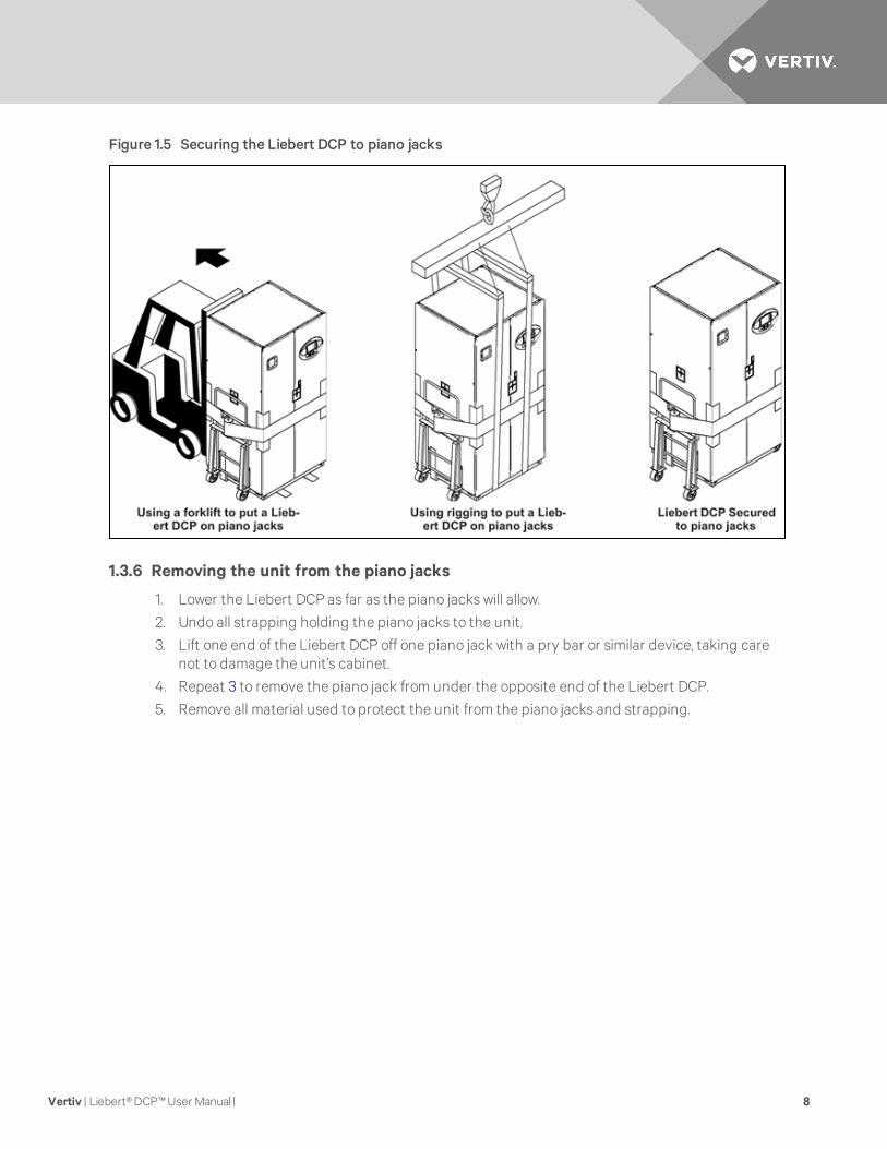
Figure 1.5 Securing the Liebert DCP to piano jacks
1.3.6 Removing the unit from the piano jacks
1. Lower the Liebert DCP as far as the piano jacks will allow.
2. Undo all strapping holding the piano jacks to the unit.
3. Lift one end of the Liebert DCP off one piano jack with a pry bar or similar device, taking carenot to damage the unit’s cabinet.
4. Repeat 3 to remove the piano jack from under the opposite end of the Liebert DCP.
5. Remove all material used to protect the unit from the piano jacks and strapping.
Vertiv | Liebert®DCP™User Manual | 8
2 INSTALLATION2.1 Mechanical Considerations
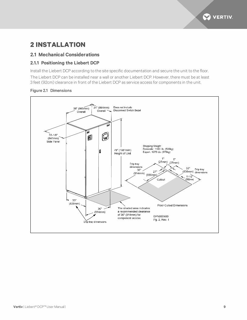
2.1.1 Positioning the Liebert DCP
Install the Liebert DCP according to the site specific documentation and secure the unit to the floor.
The Liebert DCP can be installed near a wall or another Liebert DCP. However, there must be at least3 feet (92cm) clearance in front of the Liebert DCP as service access for components in the unit.
Figure 2.1 Dimensions
Vertiv | Liebert®DCP™User Manual | 9

Figure 2.2 Piping access points
2.2 Electrical Considerations
Make sure the actual supply voltage and frequency correspond to the voltage and frequency indicatedon the Liebert DCP’s rating plate. The unit must be installed in accordance with national wiringregulations.
Connect cables for high voltage supply to the electrical box in the Liebert DCP according to Figure 2.5on page 13 and make sure that the phases are correctly connected.
WARNING! Risk of electric shock. Can cause injury or death.
Open all local and remote electric power supply disconnect switches and verify with a voltmeterthat power is Off before working within the unit’s electrical connection enclosures.
WARNING! Risk of electrical shock, short circuit and/or control malfunction. Can causeequipment damage, injury or death.Damage to wiring or components can make unit unsafe tooperate.Use caution when installing wiring to prevent damage to factory wiring.Installprotective bushings in wiring knockouts as required to protect wiring from sharp edges.Do notdisturb factory wiring or route field-installed wiring over electrical terminals.Use NECClass 1wiring for all hazardous voltage electrical power supplies.Check and retighten all wiringconnections before starting the unit.
Vertiv | Liebert®DCP™User Manual | 10

2.2.1 Connecting high-voltage cables
1. Turn the Liebert DCP’s disconnect switch to the Off position (see Figure 2.3 below). Open thefront doors and push down on the enclosure cover latch to open the hazardous voltageenclosure cover.
Figure 2.3 Front view of Liebert DCP and electrical enclosure
2. Determine which knockouts in the electrical enclosure will be used and remove them (seeFigure 2.4 on the next page).
Vertiv | Liebert®DCP™User Manual | 11

Figure 2.4 Electrical enclosure knockout location for hazardous voltage wiring
3. Route the input hazardous voltage electrical power wiring through the top left knockout (seeFigure 2.4 above) to the disconnect switch L1, L2 and L3 (see Figure 2.5 on the facing pageandFigure 2.6 on the facing page). Observe proper phasing.
4. Connect the ground wire to the ground lug (see Figure 2.5 on the facing page andFigure 2.6on the facing page), which is in the middle left of the enclosure.
Vertiv | Liebert®DCP™User Manual | 12

Figure 2.5 High voltage connections—60Hz
Figure 2.6 High voltage connections—50Hz
Vertiv | Liebert®DCP™User Manual | 13

2.2.2 Extra low voltage (ELV) connections
Extra Low Voltage power output is 30V and 100VA or less.
1. Turn off all unit power before connecting cables or wires. Failure to do so may damage thisequipment (refer to Figure 2.7 below).
2. Route low voltage electrical connections through the appropriate knockouts as indicatedbelow.
Figure 2.7 Electrical Enclosure for Extra Low Voltage
Vertiv | Liebert®DCP™User Manual | 14

Figure 2.8 Connecting the remote temperature/humidity sensors
Vertiv | Liebert®DCP™User Manual | 15

2.2.3 DIP switch and jumper settings for remote sensors
The Liebert DCP is shipped with jumpers and DIP switch settings for normal operation; refer to Figure 2.9below.Figure 2.9 DIP switch and jumper settings
Vertiv | Liebert®DCP™User Manual | 16

Figure 2.10 Unit-to-unit networking connections
2.3 Field Connections
NOTE: Field connections are optional for all units.
Connect optional field wiring from remote devices to remote alarm device, common alarm outputs, sitemonitor and remote shutdown, if applicable. See terminal strip descriptions in Figure 2.11 on the nextpage.
Vertiv | Liebert®DCP™User Manual | 17

Figure 2.11 Liebert DCP extra low voltage field connections points
2.4 Remote Sensor Installation—Proper Placement
Placement of the two remote temperature/humidity sensors is critical to effective cooling of theconditioned space.
Vertiv | Liebert®DCP™User Manual | 18

The remote sensors must be installed in areas where conditions are representative of the spaceconditioned by the Liebert DCP. Emerson® recommends installing the sensors in different areas near thecooling modules served by the Liebert DCP. If the return air side of the primary air mover, such as aLiebert DS™, represents the conditions where the cooling modules are located, one sensor could beplaced there. Emerson suggests placing the other sensor on the wall opposite the heat load area (seeFigure 2.12 below for guidance).
Do not install the sensors where ambient air might cause false readings, for example, near unsealed doorsor windows, or areas with stagnant air.
1. Unpack the two remote temperature/humidity sensors and cables.
One sensor is labeled Sensor A and the other Sensor B. The sensor cables are interchangeable;each bears labels indicating Sensor End and Unit End.
2. Connect the Sensor End of one of the supplied sensor cables to P66 on Sensor A (see Figure2.8 on page 15).
3. Connect the Unit End of the sensor cable to P67 on the Liebert iCOM® input/output boardinside the Liebert DCP. Secure the ring terminal on the cable shield to the electric boxadjacent to P67 (see Figure 2.8 on page 15).
4. Connect the Sensor End of the second sensor cable to P66 on Sensor B (see Figure 2.8 onpage 15).
5. Connect the Unit End of the cable to P67 on the Liebert iCOM display (see Figure 2.8 onpage 15). Secure the ring terminal on the cable shield to the grounding screw adjacent to P67.
Figure 2.12 Suggested remote sensor placement
Vertiv | Liebert®DCP™User Manual | 19

Vertiv | Liebert®DCP™User Manual | 20
This page intentionally left blank.

3 PIPING3.1 Connection Sizes
The copper pipe connections on the Liebert DCP are:
PIPE LINE CONNECTOR
Building Chilled Water Supply 2-5/8" OD
Chilled Water Return 2-5/8" OD
Coolant Supply 2-5/8" OD
Coolant Return 2-5/8" OD
Fill Water Source 5/8" OD
Table 3.1 Liebert DCP Pipe Connections
3.1.1 Recommended pipe size
Connect the main pipes between the Liebert DCP and the Liebert DCD™/Liebert XDK-W™ according tosite-specific documentation and the configuration guide for the Liebert DCD/Liebert XDK-W unit.
Elbows and restrictions should be minimized to get good fluid flow.
Nominal Pipe Size inches (mm) Maximum Total Equivalent Length ft. (m) Piping Material
2.5 (64) 75 (23) Type L Copper
3 (76) 150 (46) Copper or Schedule 40 Steel
3.5 (89) 300 (91) Copper or Schedule 40 Steel
Table 3.2 Supply and return requirements for Liebert DCD/Liebert XDK-W loop
3.2 Air Bleeders
Install air bleeders at each high point in the piping circuits.
3.3 Liebert DCP Interconnection with Cooling Modules
All piping must be ASTM (American Society for Testing and Materials) Type ACR copper pipe.The Liebert DCP may be connected to Liebert DCD or Liebert XDK-W cooling modules with eitherprefabricated piping assembly or rigid, off-the-shelf piping. The cooling modules are connected in parallelbetween main return and supply pipes going to and from the Liebert DCP. Figure 3.1 on the next pagerepresents a typical configuration.
Vertiv | Liebert®DCP™User Manual | 21

Figure 3.1 Liebert DCW system diagram
3.4 Piping Installation Methods
The assembly and connection means used for piping in the Liebert DCW™ system are similar to thoseused for conventional refrigeration systems. All piping should be installed with high-temperature brazedjoints. Soft soldering is not recommended.
During brazing, the lines must be filled with flowing dry nitrogen to prevent excessive oxidation and scaleformation inside the piping. Prevailing good refrigeration practices must be employed for piping supports,leak testing, dehydration and charging. Failure to use good system practices may result in damage to thesystem. Refer to the ASHRAE refrigeration handbook for general good-practice refrigeration piping.
Insulate all piping lines to prevent condensation in applications where the dew point approaches thechilled water temperature.
3.4.1 Piping mains
Install a 20-40 mesh strainer on the chilled water supply to the Liebert DCP. The strainer is needed toprevent particles in the chilled water from entering the Liebert DCP’s heat exchanger.
3.5 Bypass Flow Controllers
The Liebert DCP pumping unit is designed to provide a total of 114GPM (25.9 m3/h) of cooling water to thecooling modules. The pump operates at its highest efficiency between 90 and 120GPM (20.4m3/h and27.3m3/h). Permanent bypass flow controllers must be installed to ensure flow within this range. Emerson®
recommends using four 22.67 GPM (5.15m3/h) constant flow regulators or other regulator of similar flowcapacity as bypass valves. Bypass lines also prevent excessive flow through the cooling modules whenonly a few modules are installed in addition to maintaining high flow rate through pump.
Vertiv | Liebert®DCP™User Manual | 22

Refer to individual cooling module specifications to estimate the maximum combined allowable flow for allthe units connected to the Liebert DCP. If the allowable combined flow rate is less than 90GPM (20.4m3/h), then as many bypass controllers as necessary must be opened to maintain a flow above 90GPM(20.4m3/h) through the Liebert DCP.
For example, the maximum allowable water flow rate for a Liebert DCD™ unit is 22.7GPM (5.2 m3/h). At leastfour of these units must be connected to the Liebert DCP in parallel to achieve a total flow of over 90GPM(20.4m3/h).
22.7GPM x 4 Liebert DCD’s = 90.8GPM total flow
5.2m3/h * x Liebert DCD’s = 20.8m3/h total flow
If fewer units are connected to the Liebert DCP, then bypass lines must be opened to maintain the totalflow through the Liebert DCP within the range of 90 to 120GPM (20.4 to 27.3 m3/h).
For example, if three Liebert DCD modules are connected to a Liebert DCP, the total flow of 68.1GPM (15.47m3/h) would be insufficient. A bypass flow controller of 22.67GPM (5.15 m3/h) must be added to increasethe flow rate to at least 90GPM (20.4m3/h)
22.7GPM x 3 Liebert DCDs = 68.1GPM
22.7GPM x 3 Liebert DCDs + 22.67GPM bypass flow controller = 90.77 GPM
5.2m3/h * 3 Liebert DCDs = 15.47m3/h
5.2m3/h *3 Liebert DCDs + 5.15m3/h bypass flow controller =20.75m3/h
3.6 Piping Details—Shutoff/Isolation Valves
Isolation valves must be installed on the Liebert DCP’s secondary chilled water circuit to permitmaintenance on the unit (see Figure 3.2 below).
Figure 3.2 General piping details
Vertiv | Liebert®DCP™User Manual | 23

3.6.1 Insulation
NOTE: Do not insulate piping before checking it for leaks. Insulating pipes before checking them forleaks would prevent easy detection of leaks.
Insulate all piping between the Liebert DCP and its connected cooling modules to prevent condensationwhere the piping passes through non-conditioned areas.
3.7 Filling Instructions
This section provides detailed instructions on how to properly fill the Liebert DCP.
3.7.1 Check for proper installation of components and workmanship1. Confirm that the flow directions of field-installed components are correct.2. Confirm that all isolating valves are open (keep the hose bib valve closed when filling).3. Confirm that all auto air vents are closed (tighten caps if applicable).4. Test the water quality when filling the system. Refer to the values in 3.7.1 above for minimum
corrosion and erosion.
Maximum Conductivity 500µS/cm
Minimum PH 7.0
Maximum Suspended Matter 30 mg/L; no visible particles
Taste and Smell Normal
Table 3.3 Water quality to limit corrosion and erosion
3.7.2 Conduct air pressure test1. Turn Off power to the unit.2. Set the pressure at 150 psig (1034kPa; 10.3 bars) maximum for at least 30 minutes or according
to local codes.3. Repair any leaks if necessary.
3.7.3 Water fill line connection
NOTE: Check with local codes for proper connection to potable water and EPA conformance. Do NOTuse the hose bib at the bottom of the unit to fill the system (see Figure 3.4 on page 27 andFigure 3.3on page 26).
1. When filling the system, use only water that can be classified and used as drinking water.a. Open all vents (loosen caps if applicable) to allow air to escape during filling.b. Remove the Schrader pin in the valve at the top of the standpipe (see Figure 3.3 on
page 26) to obtain 0psig pressure.c. Open Valves #1 and #2 to allow the system to fill (see Figure 3.4 on page 27).d. When the water has reached the FILL level in the bottom sight glass of the standpipe,
immediately close Valve #1 (see Figure 3.4 on page 27) to isolate the standpipe from thesystem.
e. Replace the Schrader pin in the valve at the top of the standpipe.2. Bleed air thoroughly (keep Valve #1 closed to isolate the standpipe from the system).
a. Depress pins at all vents.b. Manually depress pins at all Schrader vents on each rack (see Figure 3.5 on page 28).
Vertiv | Liebert®DCP™User Manual | 24

c. Manually vent at pump housing plugs (see Figure 3.4 on page 27).d. Continue to vent until the system is full, then close Valve #2.
3. Open Valve #1 to reconnect the system to the standpipe (fluid level should rise above the fill,but below the NORMAL level on the sight glass).
a. If the fluid level is above the NORMAL level, release water by opening the hose bib untilthe level reaches the NORMAL level on the sight glass.
b. If the fluid level is below the NORMAL level on the sight glass, open Valve #2 until thelevel reaches the NORMAL level.
4. Turn the system on (pumps will be in operation) and continue to vent air for 24 hours toremove as much air as possible.
If 1 through3. above are followed properly, the air pressure in the top of the standpipe should be14 PSIG (±2PSIG).
NOTE: Add water as necessary to maintain a normal level reading.
5. When the system is mostly air-free, close all air vents (tighten caps securely); this includesvents at each rack (Figure 3.5 on page 28) and auto air vents on the main headers.
6. Conduct a Fluid Pressure Test.
a. Pressure test the system with water at city pressure for six hours or according to localcodes.
b. Check for leaks.
7. Add a water corrosion inhibitor.
• The use of a closed system treatment (CST) is strongly recommended. CST is availablefrom Terlyn Industries at 800-200-4112 or www.terlyn.com.
• Additional treatment might be required after six to 12 months of operation, depending onthe quality of your water.
Note: Many parameters contribute to water corrosion and erosion, and the requirementsstated above do not guarantee 100% corrosion and erosion prevention. However, when theseparameters are met and a corrosion inhibitor is used, the possibility of corrosion and erosion inthe closed loop water system should be minimized, therefore maximizing the life expectancy ofthe system.
8. Refill the system by following 1 through5. above, then go to 9.
9. Turn the unit On by pressing the I/O key.
Vertiv | Liebert®DCP™User Manual | 25

Figure 3.3 Standpipe filling components
Vertiv | Liebert®DCP™User Manual | 26

Figure 3.4 Liebert DCP filling components
Vertiv | Liebert®DCP™User Manual | 27

Figure 3.5 Liebert DCD™ bleed valve
Figure 3.6 Liebert XDK-W™ bleed valve
3.8 Checklist for Proper Installation
1. Unpack and check received material.
2. Position the Liebert DCP and secure to the floor.
3. Wire high-voltage connections.
4. Wire low-voltage connections.
5. Connect building chilled water piping to the Liebert DCP.
6. Connect Liebert DCD™/Liebert XDK-W piping to the Liebert DCP.
7. Make sure air vents are installed at high-point of the system.
8. Make sure isolation valves are installed on the mains and branch piping.
9. Pressure test air.
10. Fill the system with water.
Vertiv | Liebert®DCP™User Manual | 28

11. Bleed air out of the system.
12. Pressure test fluid.
13. Check for water leaks.
Vertiv | Liebert®DCP™User Manual | 29

Vertiv | Liebert®DCP™User Manual | 30
This page intentionally left blank.

4 LIEBERT ICOM® CONTROL
The following sections apply to firmware Version XP1.00.DCP.01R.
4.1 Liebert iCOM Components and Functions
The Liebert iCOM controller layout is shown in Figure 4.1 below; the keyboard functions are defined in 4above.
Figure 4.1 Liebert iCOM display components
Vertiv | Liebert®DCP™User Manual | 31

Icon KeyName Function
On/Off Key Controls the operational state of the cooling unit.
Alarm Key Silences an alarm.
Help Key Accesses integrated Help menus.
ESCape Key Returns to the previous display view.
Enter Key Confirms all selections and selects icons or text.
Increase Key(Up Arrow) Moves upward in a menu or increases the value of a selected parameter.
Decrease Key(Down Arrow) Moves downward in a menu or reduces the value of a selected parameter.
Left and RightArrow Keys Navigates through text and sections of the display.
Upper LED
Blinking Red—Active, unacknowledged alarm exists
Solid Red—Active, acknowledged alarm exists
Lower LED
Amber—Power is available to the unit; unit is NOT operating
Green—Unit is operating with no alarms
Table 4.1 Keyboard icons and functions
4.2 Display Lamp Indicators
• The Green lamp will be On only when the Liebert DCP is On and running with no alarms.
• The Red lamp will be On if the unit is On and running with an active alarm, or if the unit is shutdown because of an alarm.
• The Red lamp will flash while an alarm is being annunciated. The Red lamp will stop flashingand the beeper in the display will stop beeping when the ALARM SILENCE / ? key is pressed.
• The Amber lamp will be On if the Liebert DCP has been shut down at the I/O switch or if theunit has been shut down by an alarm condition.
4.3 Navigating Through the Liebert iCOM® Display
Liebert iCOM displays icons and text for monitoring and controlling your Liebert cooling unit. The LiebertiCOM’s home screen is shown in Figure 4.2 on the facing page.
Vertiv | Liebert®DCP™User Manual | 32
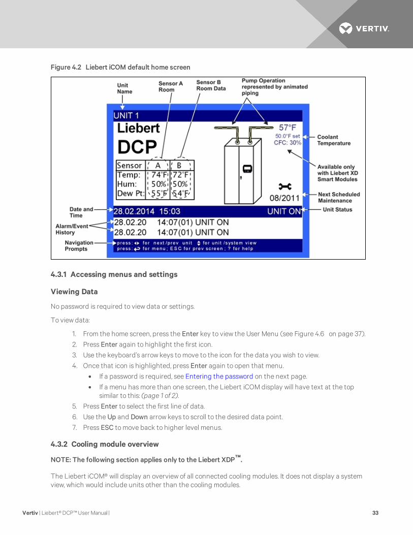
Figure 4.2 Liebert iCOM default home screen
4.3.1 Accessing menus and settings
Viewing Data
No password is required to view data or settings.
To view data:
1. From the home screen, press the Enter key to view the User Menu (see Figure 4.6 on page 37).
2. Press Enter again to highlight the first icon.
3. Use the keyboard’s arrow keys to move to the icon for the data you wish to view.
4. Once that icon is highlighted, press Enter again to open that menu.
• If a password is required, see Entering the password on the next page.
• If a menu has more than one screen, the Liebert iCOM display will have text at the topsimilar to this: (page 1 of 2).
5. Press Enter to select the first line of data.
6. Use the Up and Down arrow keys to scroll to the desired data point.
7. Press ESC to move back to higher level menus.
4.3.2 Cooling module overview
NOTE: The following section applies only to the Liebert XDP™.
The Liebert iCOM® will display an overview of all connected cooling modules. It does not display a systemview, which would include units other than the cooling modules.
Vertiv | Liebert®DCP™User Manual | 33

NOTE: The Liebert iCOM control screens display a setting to select a system view, but the Liebert DCPdoes not support a system view.
To display an overview of all connected cooling modules:
1. At the default home screen on the Liebert iCOM, press the Down arrow. This will display thefirst 10 modules’ outlet temperature and capacity levels. Press ESC to return to the unit view.
Figure 4.3 Cooling module overview, first 10modules—Applies only to Liebert XDP
2. Press the down arrow button again to display the next 10 modules’ outlet temperature andcapacity levels.
3. Press ESC to return to the default home screen.
4.3.3 Entering the password
Most settings in the Liebert iCOM® are protected by a factory-set password, 1490. To enter the password:
1. From the home screen, press the Enter key to view the User Menu (see Figure 4.6 on page 37).
2. Press Enter again to highlight the first icon.
3. Use the keyboard’s arrow keys to move to the icon for the data you wish to change.
4. Once that icon is highlighted, press Enter again to open that menu.
5. Press Enter to highlight the Password line.
6. With the Password line highlighted, press Enter to highlight the first digit in the password
7. Enter the password, 1490.
Use the Up and Down arrow keys to select a numeral for the first digit of the password.
Move to the next digit of the password with the Right arrow key.
Select the numerals for all four digits with the same process.
8. After all four digits of the password have been entered, press the Enter key.
NOTE: Do not press the ESC key or the Liebert iCOM will move to the previous screen and thepassword must be re-entered before changes may be made.
Vertiv | Liebert®DCP™User Manual | 34

Figure 4.4 Entering the password
4.4 Changing Liebert iCOM®’s Display Settings
No password is required to change the way Liebert iCOM displays data. The Display Setup controls howthe unit shows data, such as temperature, date and time.
To change the display settings:
1. From the home screen, press the Enter key to view the User Menu (see Figure 4.6 on page 37).
2. Press Enter again to highlight the first icon.
3. Use the keyboard’s arrow keys to move to the Display Setup icon.
4. Once that icon is highlighted, press Enter again to open that menu.
5. Press the Enter key to select the first setting.
Either change that setting or navigate to another setting with the Up and Down arrow keys.
6. Once the desired setting is highlighted, press the Enter key to access that parameter’s displaysetting options.
7. Use the Up and Down arrow keys to make changes.
8. Press the Enter key to accept the changes.
9. Press the ESC key twice to return to Liebert iCOM’s user menu.
Vertiv | Liebert®DCP™User Manual | 35

Figure 4.5 Display setup screen
4.5 Changing Operational Settings
Changes to the Liebert DCP’s operation settings in the Set Alarms and Setpoints menus require apassword.
1. From the home screen, press the Enter key to view the User Menu (see Figure 4.6 on thefacing page).
2. Press Enter again to highlight the first icon.
3. Use the keyboard’s arrow keys to move to the icon for the data you wish to change.
4. Once that icon is highlighted, press Enter again to open that menu.
If a password is required, see Entering the password on page 34.
5. After entering the password, use the Up and Down arrow keys to scroll to and highlight theoperational setting to be changed.
6. Press Enter to highlight the values for that setting.
7. Use the Up and Down arrow keys to change the value.
8. Press Enter to accept the change. (The value will no longer be highlighted.)
9. Press ESC to deselect the operational setting. (The setting will no longer be highlighted.)
10. Press ESC again to move to previous screens.
4.6 Graphical Data Record
The Graphical Data Record charts the average temperature from Sensors A and B and the supply coolanttemperature.
The temperature scales can be changed to expand or compress the data.
The time scale also can be altered to any of several selectable values.
Vertiv | Liebert®DCP™User Manual | 36

NOTE: Changing the time scale eliminates all previous graphical data and the unit will begin recordingnew data.
4.7 Liebert iCOM® User Menu Icons and Legend
Setpoints
View and changeoperationalsetpoints
Spare Parts List
Contains spareparts available onsite
Event Log
Lists last 400events and alarms
View Only
Graphic Data Record
Displays average temperature fromSensors A and B, the average dew pointfrom Sensors A and B, the supply coolanttemperature and the supply coolant controlpoint graphs; Data is View Only; Displayscale is adjustable
View Network
Shows status ofall connectedunits; View Only
Set Alarms
Allows user tochange settingsfor alarms
Sensor Data
Shows readings ofsensors; ViewOnly
Active Alarms
Lists all currentalarms; View Only
Display Setup
Change settingsfor display:language and time
Total Run Hours
Records the run time of all componentsand allows setting of limits on run time;View Only
Smart Modules
Displays readingsfor the individualsmart modules;View Only; appliesonly to LiebertXDP™
Service Contacts
Contains keycontactinformation forservice
Table 4.2 Liebert iCOM UserMenu icons
Figure 4.6
NOTE: Menu shows icons only; text is explanatory and does not appear on the Liebert iCOM display.
Figure 4.7 Liebert DCP User Menu screen
4.8 Liebert iCOM® User Menu Screens
User menus report general cooling unit operations and status. User menu screens employ a coding thatbegins with “U” and is followed by parameters and information, such as settings. Gaining access to someUser menu screens requires entering a password; the User Menu password is 1490.
Check www.liebert.com for the latest Liebert iCOM user manual updates, SL-18835.
Vertiv | Liebert®DCP™User Manual | 37
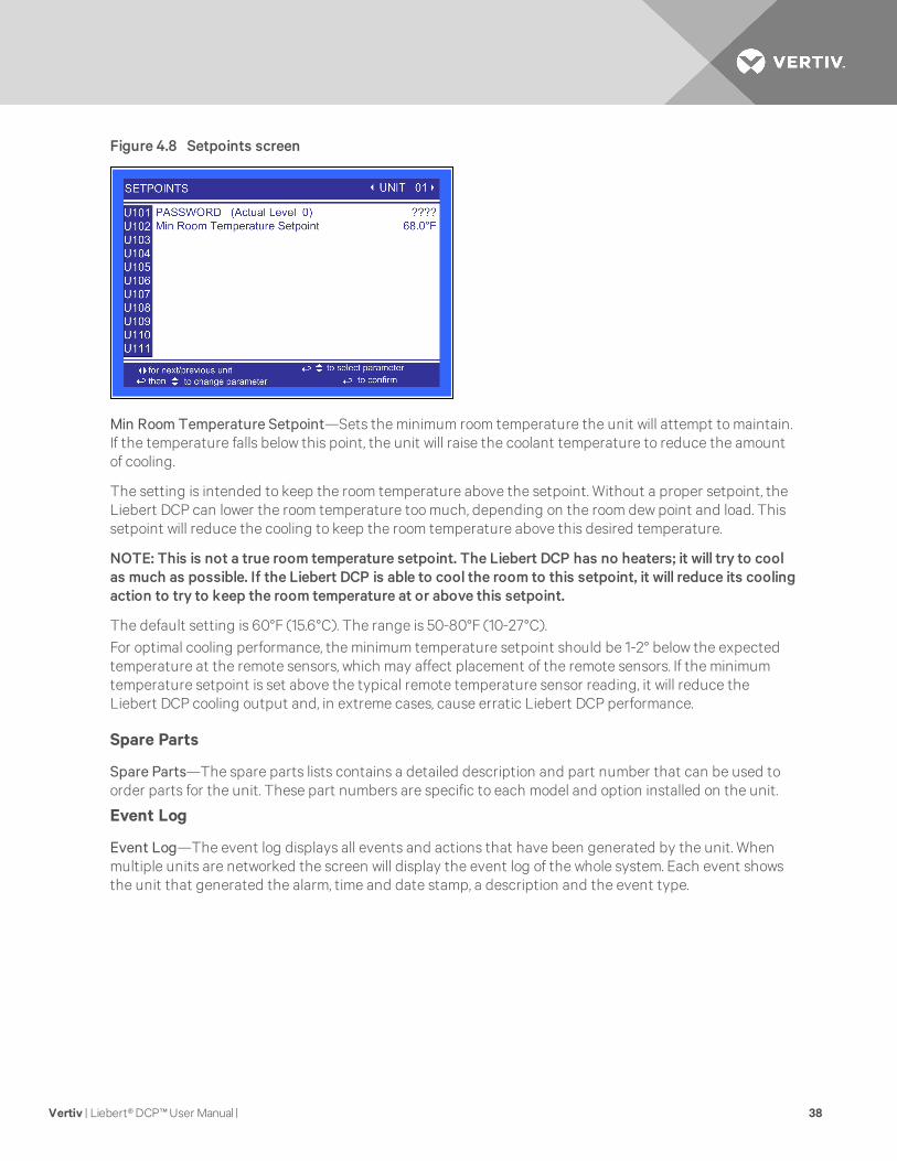
Figure 4.8 Setpoints screen
Min Room Temperature Setpoint—Sets the minimum room temperature the unit will attempt to maintain.If the temperature falls below this point, the unit will raise the coolant temperature to reduce the amountof cooling.
The setting is intended to keep the room temperature above the setpoint. Without a proper setpoint, theLiebert DCP can lower the room temperature too much, depending on the room dew point and load. Thissetpoint will reduce the cooling to keep the room temperature above this desired temperature.
NOTE: This is not a true room temperature setpoint. The Liebert DCP has no heaters; it will try to coolas much as possible. If the Liebert DCP is able to cool the room to this setpoint, it will reduce its coolingaction to try to keep the room temperature at or above this setpoint.
The default setting is 60°F (15.6°C). The range is 50-80°F (10-27°C).For optimal cooling performance, the minimum temperature setpoint should be 1-2° below the expectedtemperature at the remote sensors, which may affect placement of the remote sensors. If the minimumtemperature setpoint is set above the typical remote temperature sensor reading, it will reduce theLiebert DCP cooling output and, in extreme cases, cause erratic Liebert DCP performance.
Spare Parts
Spare Parts—The spare parts lists contains a detailed description and part number that can be used toorder parts for the unit. These part numbers are specific to each model and option installed on the unit.
Event Log
Event Log—The event log displays all events and actions that have been generated by the unit. Whenmultiple units are networked the screen will display the event log of the whole system. Each event showsthe unit that generated the alarm, time and date stamp, a description and the event type.
Vertiv | Liebert®DCP™User Manual | 38

Figure 4.9 Set Alarms screen
High Room Air Temperature—Sets the threshold where a high room temperature alarm will occur, basedon the actual reading from either remote Sensor A or B. The range for the high room air temperaturealarm is 33.8-95°F (1-35°C); the default is 80.0°F (26.7°C).Low Room Air Temperature—Sets the threshold where a low room temperature alarm will occur, based onthe actual reading from either remote Sensor A or B. The range for the high room air temperature alarm isfrom 33.8 to 95°F (1 to 35°C); the default is 55.0°F (12.8°C).High Room Dewpoint—Sets the threshold where a high room dew point alarm will occur, based on thecalculated values from either remote Sensor A or remote Sensor B. The range for the high room dew pointalarm is from 33.8 to 95°F (1 to 35°C); the default is 65°F (18.3°C).High Coolant Temperature—Sets the threshold where a high coolant temperature alarm will occur basedon the actual reading from the supply coolant sensor. The supply coolant temperature is from the LiebertDCP to the modules. The range for the high supply coolant temperature alarm is from 33.8 to 95°F (1 to35°C); the default is 80°F (26.7°C).High Chilled Water Temperature—Sets the threshold chilled water temperature for a supply high chilledwater temperature alarm. The range for the high supply fluid temperature alarm is from 33.8 to 95°F (1 to35°C); the default is 60°F (15.6°C).
Figure 4.10 Sensor Data screen, page 1 of 2
Sensor A Temperature—Displays the temperature of the remote CAN Temp Humidity sensor designatedas Sensor A.
Vertiv | Liebert®DCP™User Manual | 39

Sensor A Humidity—Displays the humidity of the remote CAN Temp Humidity sensor designated asSensor A.
Sensor A Dew Point—Displays the dew point of the remote CAN Temp Humidity sensor designated asSensor A.
Sensor B Temperature—Displays the temperature of the remote CAN Temp Humidity sensor designatedas Sensor B.
Sensor B Humidity—Displays the humidity of the remote CAN Temp Humidity sensor designated asSensor B.
Sensor B Dew Point—Displays the dew point of the remote CAN Temp Humidity sensor designated asSensor B.
Supply Coolant Temperature—Displays the actual supply coolant temperature from the Liebert DCP tothe modules.
Supply Chilled Water Temperature—Displays the actual the Supply Chilled Water temperature to theLiebert DCP.
Figure 4.11 Sensor Data screen, page 2 of 2
Daily High Temperature—Shows the highest temperature in a rolling 24 hour period for either remoteSensor A or remote Sensor B.
Daily Low Temperature—Shows the lowest temperature in a rolling 24 hour period for either remoteSensor A or remote Sensor B.
Daily High Humidity—Shows the highest humidity in a rolling 24 hour period for either remote Sensor A orremote Sensor B.
Daily Low Humidity—Shows the lowest humidity in a rolling 24 period for either remote Sensor A orremote Sensor B.
Daily High Dew Point—Shows the highest dew point in a rolling 24 hour period for either remote Sensor Aor remote Sensor B.
Daily Low Dew Point—Shows the lowest dew point in a 24 hour period for either remote Sensor A orremote Sensor B.
Vertiv | Liebert®DCP™User Manual | 40

Daily High Coolant Temperature—Shows the highest supply coolant temperature in a rolling 24 hourperiod from the Liebert DCP to the modules.
Daily Low Coolant Temperature—Shows the lowest supply coolant temperature in a rolling 24 hour periodfrom the Liebert DCP to the modules.
Daily High Chilled Water Temperature—Shows the highest chilled water supply temperature beingdelivered to the Liebert DCP in a rolling 24 hour period.
Daily Low Chilled Water Temperature—Shows the lowest chilled water return temperature beingdelivered to the Liebert DCP in a rolling 24 hour period.
Figure 4.12 Display Setup screen
Language—Sets the language on the display. Changing this setting changes all menu parameters to theselected language.
Date—Sets the internal date of the unit. If this unit is connected to other units with the unit-to-unitnetwork connection, each unit will reflect the last date set.
Time—Sets the internal time of the unit. If this unit is connected to other units with the unit-to-unitnetwork connection each unit will reflect the last time set.
Temperature Indication—Selects the actual and setpoint temperature scale. Selecting C will set the unitto display in Celsius and F will set the unit to display in Fahrenheit.
Display Contrast—Changes the contrast of the display to adjust for different viewing angles, low light andbright light conditions. As the display ages, the contrast may require adjustment for viewing.
Buzzer Frequency—Changes the audible noise frequency of the built-in buzzer. The buzzer will soundwhen its frequency is being adjusted, easing selection of a frequency easily detected when an alarmoccurs.
Backlite Off After—Controls how long the back-light remains active when the display is unused. Whenthe buttons on the front display have not been pressed for the time selected in this parameter, the back-light will turn Off, extending the life of the display and saving energy.
Screen—Controls the screen layout. The Liebert DCP has one view, Unit View.
Display Colors—Selects the background color. Inverted sets the display to show white font with bluebackground and Normal sets a white background with blue font.
Vertiv | Liebert®DCP™User Manual | 41

Date Format—Date format changes the month, day and year arrangement shown on the front display andon event time stamps.
Figure 4.13 Module Status screen, page 1 of 20—Applies to Liebert XD™ smart modules only
Module Node ID—The location within the CANbus. Each module’s ID is factory-set to 80 and isautomatically changed during setup; requires no user action.
Module Labels—A four-character label consisting of two letters and two numerals. This is the standardnomenclature for Data Center Grid assignment of racks. Additionally, the module’s location can bedenoted with 10 characters, either letters or non-alphanumeric characters from a built-in list. Either orboth labels can be used and are entered using the Module Setup found in the Service menu (S910).
Module Status—Indicates whether the smart module is connected to the CANbus.
Figure 4.14 Liebert XDV™ Smart Module Status screen—Applies to Liebert XD smart modules only
U905—Displays the temperature of the air entering the Liebert XDV™.
U908—Displays the temperature of the air leaving the right and left fan of the Liebert XDV.
U911—Displays the module type and calculated local module capacity; possible module types areXDV8SK, XDV8SS, XDV8ST, XDV10SK, XDV10SS and XDV10ST.
U912—Displays the left fan status; possible values are ON and OFF.
U913—Displays the right fan status; possible values are ON, OFF and ON ECON. ON ECON indicates thatonly one fan is On.
Vertiv | Liebert®DCP™User Manual | 42

Figure 4.15 Liebert XDH™ Smart Module Status screen—each bank shown separately—Applies toLiebert XD™ smart modules only
U904—Displays the temperature of the air entering the top of the bank of the Liebert XDH.
U905—Displays the temperature of the air leaving the Liebert XDH.
U907—Displays the temperature of the air entering the bottom of the bank of the Liebert XDH.
U911—Displays the module type and calculated local module capacity; possible module types areXDH20SK, XDH20SS, XDH32SK and XDH32SS.
U912—Displays the middle fan status; possible values are ON and OFF.
U913—Displays the top and bottom fans’ status; possible values are ON, OFF and ON ECON. (ON ECONindicates that two fans have been turned On.)
Figure 4.16 Liebert XDO™ Smart Module Status screen—Applies to Liebert XD™ smart modules only
U907—Displays the temperature of the air entering from the right and left of the Liebert XDO.
U910—Displays the temperature of the air leaving the Liebert XDO.
U911—Displays the module type and calculated local module capacity; possible module types XDO16SK,XDO16SS and XDO20SS.
U912—Displays the fan status; possible values are ON and OFF.
Vertiv | Liebert®DCP™User Manual | 43

Figure 4.17 Total Run Hours screen
The parameter shows the actual hours Pump 1 and Pump 2 have operated and the maximum time Pump 1can operate before the next maintenance.
4.9 Liebert iCOM® Service Menu Icons and Legend
Setpoints
View and changeoperational setpoints
Unit Diary
Shows all programchanges andmaintenanceperformed,
Maintenance/WellnessSettings
Shows all maintenancerecords, calculatesnext maintenance date
Diagnostics/Service Mode
Enter Diagnostics/ServiceMode for troubleshootingand repair
Set Alarms
Change settings foralarms
SensorCalibration/Setup
Setup and calibratesensors for site
Network
Setup or alternetwork setting.
Options Setup
Enter specific settingsfor various options
Smart Module
Setup of alarms andevents. Set temperaturelimits for supply and returnsensors. Label smartmodules, view firmwareversion; applies only toLiebert XDP™
Service Contacts
Contains key contactinformation forservice
Table 4.3 Liebert iCOM Service Menu icons
NOTE: Menu shows icons only; text is explanatory and does not appear on the Liebert iCOM display.
Vertiv | Liebert®DCP™User Manual | 44

Figure 4.18 Liebert DCP Service Menu screen
4.10 Liebert iCOM® Service Menu Screens
Service menus allow customized settings for site operations. Service Menu screens employ a coding thatbegins with “S” and is followed by parameters and information, such as settings. Gaining access to mostService Menus requires entering a password; the Service Menu password is 5010; see Entering thepassword on page 34 for assistance.The Liebert iCOM firmware is being updated constantly. As a result, the Service Menu parameters in thismanual may be slightly different from what is shown on a cooling unit’s display. Check www.liebert.com forthe latest Liebert iCOM user manual updates.
Figure 4.19 Setpoints screen
Min Room Temperature Setpoint—Sets the minimum room temperature the unit will attempt to maintain.If the temperature falls below this point, unit will raise the coolant temperature to reduce the amount ofcooling. Adjustable from 50 to 80°F (10.0 to 26.7°C), the factory default setting is 60°F (15.6°C).
NOTE: This is not a true room temperature setpoint. The Liebert DCP has no heaters; it will try to coolas much as possible. If the Liebert DCP is able to cool the room to this setpoint, it will reduce its coolingaction to try to keep the room temperature at or above this setpoint.
Vertiv | Liebert®DCP™User Manual | 45
Temperature Control Type—Selects the type of control the system will use to activate cooling. TheLiebert iCOM® control has three temperature control types: Proportional, PI and Intelligent. The factorydefault is Intelligent.
• Proportional—If Proportional Control is selected, the percent cooling requirement isdetermined by the difference between the air temperature sensor reading and thetemperature setpoint. As the air temperature rises above the temperature setpoint, thepercent cooling required increases proportionally (from 0 to 100%) over half the programmabletemperature proportional band. The percent heating requirement (0 to 100%) is determinedthe same way when the air temperature falls below the setpoint.
• PI—If PI Control is selected, the percent cooling requirement is calculated by adding togethertwo individual terms, proportional and integral. The proportional term is calculated in a mannersimilar to the previously described Proportional control. The integral term (sometimes calledreset action) is calculated by measuring how much and for how long the air temperature hasbeen above or below the setpoint. If the actual air temperature is above the setpoint, thepercent requirement is slowly but continuously increased until the total is sufficient to bringthe return room air back to the setpoint.
• Intelligent—If Intelligent Control is selected, the air temperature is controlled at or near thesetpoint. The percent temperature adjustment required is calculated based on logic that isprogrammed into the control. These rules simulate the actions that would be taken by ahuman operator manually controlling the system.
Temperature Proportional Band—Adjusts the activation points of compressors or rate of change basedon the actual sensor values deviation from setpoint. The smaller this number the faster the compressorsand valve(s) will increase capacity. Too small of a number may cause the unit to short cycle thecompressors or excessively reposition the valve. This parameter is adjustable from 1.8 to 54.0°F (1.0 to30.0°C). The factory default setting is 7.0°F (3.9°C).
Temperature Integration Time—Temperature integration takes into consideration the amount of timethe actual temperature has deviated from the setpoint. The larger this deviation is the longer the unit willwait before corrective action is taken to achieve the setpoint. This parameter is adjustable from 0 to 15minutes. The factory default is 0.
Temperature Derivative Time—Monitors the rate of change and will reduce or increase the amount ofcorrective action based on the actual temperature increasing or decreasing toward the temperaturesetpoint. This parameter is adjustable from 0-900 seconds. The factory default is 0.
Dewpoint Margin—Selects the difference between the room dew point and the coolant temperaturecontrol point. This parameter is adjustable from 4.0 to 10.0°F (2.2 to 6.0°C). The factory default is 4.0°F(2.2°C).
Minimum Control Point—Sets the minimum supply coolant temperature the Liebert DCP will maintain.This parameter is adjustable from 40 to 113°F (4.4 to 45.0°C). The factory default is 55°F (12.8°C).
Min Percent Cooling Setpoint—Selects the lowest percent call for cooling during normal operations.Whenever the unit is not in startup mode or OFF, the percent call for cooling cannot go below this value.The parameter is adjustable from 0 to 30%. The factory default is 15%.
Vertiv | Liebert®DCP™User Manual | 46

Figure 4.20 Maintenance—Basic Settings screen, page 1 of 7
Maintenance Frequency Per Year—Sets the number of expected maintenance visits in a one year timespan.Max Bonus—Increases the time until the next required maintenance. Service personnel should assign abonus when a service visit finds all components working optimally.Max Penalty—Decreases the time until the next maintenance cycle. Service personnel should assign apenalty when a service visit finds excessive wear on components.Last Maintenance—Date set during the service call. It also indicates to other service personnel the date ofthe last visit.Service Engineer—Provides a label for the service representative to list either the company name orrepresentative’s name.Confirm PM—Confirms that the service representative has completed the preventive maintenance andresets the next maintenance date.Calculated Next Maintenance—Provides a date to for the next expected maintenance based on the lastpreventive maintenance performed (Confirm PM), component starts, run hours and the penalty or bonusset in the Liebert iCOM® control.
Figure 4.21 Maintenance—Pump 1 Settings screen, page 2 of 7
Number of Starts—Shows the number of starts for the unit’s Pump 1.
Run Hours—Shows the number of run hours for the unit’s Pump 1.
Average Run Time—Shows the average run time of the unit’s Pump 1.
Vertiv | Liebert®DCP™User Manual | 47

Starts per Day Best—Displays the lowest number of starts in a rolling 24 hour period for Pump 1.
Starts per Day Worst—Displays the highest number of starts in a rolling 24 hour period for Pump 1.
Number of Alarms—Displays the number of alarms that have occurred with the unit’s Pump 1.
Actual Bonus—Displays the actual calculation of wellness for the unit’s Pump 1. The unit will always takethe value from the worst component for the next maintenance indication.
Figure 4.22 Maintenance—Pump 2 Settings screen, page 3 of 7
Number of Starts—Shows the number of starts for the unit’s Pump 2.Run Hours—Shows the number of run hours for the unit’s Pump 2.Average Run Time—Shows the average run time of the unit’s Pump 2.Starts per Day Best—Displays the lowest number of starts in a rolling 24 hour period for Pump 2.
Starts per Day Worst—Displays the highest number of starts in a rolling 24 hour period for Pump 2.Number of Alarms—Displays the number of alarms that have occurred with the unit’s Pump 2Actual Bonus—Displays the actual calculation of wellness for the unit’s Pump 2. The unit will always takethe value from the worst component for the next maintenance indication.
Vertiv | Liebert®DCP™User Manual | 48

Figure 4.23 Maintenance screens, pages 4 through 7
Pages 4 through 7 apply only to the Liebert XDC™. No Liebert DCP parameters are present.
Figure 4.24 Diagnostics/Service Mode screen, page 1 of 6
Page 1 applies to the Liebert XDC™ only. No Liebert DCP parameters are present.
Vertiv | Liebert®DCP™User Manual | 49

Figure 4.25 Diagnostics/Service Mode screen, page 2 of 6
Manual Mode—Used to place the Liebert iCOM® in manual mode. This is the initial setting necessary toactivate any of the following items. When the Liebert iCOM is not in manual mode, each service menu itemshows the current status of each parameter.
Pump 1—Starts the unit’s Pump 1.
Pump 2—Starts the unit’s Pump 2.
3P Start Active/Complete—Displays if the startup routine is active, and if it is completed.
3P Actuator Input Request—Shows the percent call for cooling.
3P Actuator Position—Sets the position of the actuator 0-100% in manual mode.
3P Actuator Open—Opens the 3P actuator when set to ON in manual mode.
3P Actuator Close—Closes the 3P actuator when set to ON in manual mode
Valve Feedback—Opens the valve percent in manual mode.
Figure 4.26 Diagnostics/Service Mode screen, page 3 of 6
Page 3 applies to the Liebert XDC™ only. No Liebert DCP parameters are present.
Vertiv | Liebert®DCP™User Manual | 50

Figure 4.27 Diagnostics/Service Mode screen, page 4 of 6
Manual Mode Control Type—Not currently used.
Manual Deviation—Not currently used.
Analog Output Ramp 1—Sets the value of Analog Output 1 value as a percentage. The factory default forthe Liebert DCP is the Valve Percent Open.
Analog Output Ramp 2—Sets the value of Analog Output 2 value as a percentage. The factory default forthe Liebert DCP is the Call for Cooling.
Analog Output Ramp 3—Sets the value of Analog Output 3 value as a percentage. The factory default forthe Liebert DCP is the CW Temp.
Analog Output Ramp 4—Sets the value of Analog Output 4 value as a percentage. The factory default forthe Liebert DCP is the coolant temperature.
Alarm Relay—Used to activate the Liebert iCOM® common alarm relay output.
Warning Relay—Used to activate the Liebert iCOM’s warning relay output.
Figure 4.28 Diagnostics/Service Mode screen, page 5 of 6
Status Remote Shutdown—Displays the status of the unit’s remote shutdown input.
Status Fan Failure—Displays the status of the dry contact to communicate fan failure at a module. (Thedry contacts are not used to communicate a fan failure alarm when using CANbus.)
Status Diff Press Switch 1—Displays the status of the differential pressure switch.
Status Customer Input 1—Displays the status of the customer input 1 alarm.
Vertiv | Liebert®DCP™User Manual | 51

Status Condensation Detect—Displays the status of the dry contact to communicate condensatedetection at a module.
Status Unit Ready—Shows unit status when a secondary device, such as a fire detection system, isemployed.
Figure 4.29 Diagnostics/Service Mode screen, page 6 of 6
Page 6 applies to the Liebert XDC™ only. No Liebert DCP parameters are present.
Figure 4.30 Set Alarms screen, page 1 of 7
High Room Air Temperature—Sets the threshold for a high room air temperature alarm. The range for thehigh room air temperature alarm is from 33.8 to 95°F (1 to 35°C); the default is 80°F (26.7°C).
Low Room Air Temperature—Sets the threshold for a low room air temperature alarm. The range for thelow room air temperature alarm is from 33.8 to 95°F (1 to 35°C); the default is 55°F (12.8°C).
High Room Dewpoint—Sets the threshold for a return high dew point alarm. The range for the high roomdew point alarm is from 33.8 to 95°F (1 to 35°C); the default is 65°F (18.3°C).
High Coolant Temperature—Sets the threshold for a high a coolant temperature alarm. The range for thehigh supply coolant temperature alarm is from 33.8 to 122°F (1 to 50°C); the default is 80°F (26.7°C).
High Chilled Water Temperature—Sets the threshold chilled water temperature for a supply high chilledwater temperature alarm. The range for the high supply fluid temperature alarm is from 33.8 to 113°F (1 to45°C); the default is 60°F (15.6°C).
Vertiv | Liebert®DCP™User Manual | 52

Figure 4.31 Set Alarms screen, page 2 of 7
Customer Input 1—Selects the device and operation of the customer input. Each event reflects a differentalarm and possible action to the unit. Selectable options are:
• Call Service
• C-Input
• Water
• Smoke
Customer Input 1 active when—Selects whether the Customer Input 1 input is normally closed or normallyopen.
WARNING ACTIVATES ALARM RELAY—Sets the alarm relay (K3) to activate when a warning occurs.
Reset Disabled Alarms—Resets disabled events.
The Set Alarm Screens (Figure 4.32 on the next page throughFigure 4.36 on page 57) permit settingthe operation of an active alarm. Each event can be enabled or disabled and can be set to operate as analarm, warning or message. The delay is the time the control waits before reporting the event.
• Alarm: Annunciates the buzzer, triggers a monitoring event, triggers the alarm relay andflashes the red LED on the display.
• Warning: Annunciates the buzzer, triggers a monitoring event, shows the event in the eventviewer / front display and flashes the red LED on the display.
• Message: Shows the event in the event viewer and on the front display.
Vertiv | Liebert®DCP™User Manual | 53

Figure 4.32 Set Alarms screen, page 3 of 7
HIGH TEMP SENSOR A—Enables or disables the High Temperature Sensor A event, which occurs whenthe reading from Sensor A is above the user-specified alarm setpoint. Sets how the event is reported: asan alarm, a warning or a message. Specifies how long the control waits before reporting the event.
LOW TEMP SENSOR A—Enables or disables the Low Temperature Sensor A event, which occurs whenthe reading from Sensor A is below the user-specified alarm setpoint. Sets how the event is reported: asan alarm, a warning or a message. Specifies how long the control waits before reporting the event.HIGH TEMP SENSOR B—Enables or disables the High Temperature Sensor B event, which occurs whenthe reading from Sensor B is above the user-specified alarm setpoint. Sets how the event is reported as analarm, a warning or a message. Specifies how long the control waits before reporting the event.LOW TEMP SENSOR B—Enables or disables the Low Temperature Sensor B event, which occurs whenthe reading from Sensor B is below the user-specified alarm setpoint. Sets how the event is reported: as analarm, a warning or a message. Specifies how long the control waits before reporting the event.HIGH DEWPOINT—Enables or disables the High Dewpoint event, which occurs when the calculated dewpoint at Sensor A or Sensor B is above the user-specified alarm setpoint. Sets how the event is reported: asan alarm, a warning or a message. Specifies how long the control waits before reporting the event.SENSOR A FAILURE—Enables or disables the Sensor A Failure event, which occurs when the control nolonger senses a signal from Sensor A. Sets how the event is reported: as an alarm, a warning or a message.Specifies how long the control waits before reporting the event.SENSOR B FAILURE—Enables or disables the Sensor B Failure event, which occurs when the control nolonger senses a signal from Sensor B. Sets how the event is reported: as an alarm, a warning or a message.Specifies how long the control waits before reporting the event.HIGH CHILLED WATER TEMP—Enables or disables the High Chilled Water Temp event, which occurswhen the reading from Supply Chilled Water Sensor is above the user-specified alarm setpoint. Sets howthe event is reported: as an alarm, a warning or a message. Specifies how long the control waits beforereporting the event.SUPPLY CW SENSOR FAILURE—Enables or disables the Supply CW Sensor Failure event, which occurswhen the control no longer senses a signal from Supply CW Sensor. Sets how the event is reported: as analarm, a warning or a message. Specifies how long the control waits before reporting the event.
Vertiv | Liebert®DCP™User Manual | 54

Figure 4.33 Set Alarms screen, page 4 of 7
HIGH COOLANT TEMP—Enables or disables the High Coolant Temp event, which occurs when thereading from supply coolant temperature sensor is above the user-specified alarm setpoint. Sets how theevent is reported: as an alarm, a warning or a message. Specifies how long the control waits beforereporting the event.
LOW COOLANT TEMP—Enables or disables the Low Coolant Temp event, which occurs when thereading from supply coolant temperature sensor is below the user-specified alarm setpoint. Sets how theevent is reported: as an alarm, a warning or a message. Specifies how long the control waits beforereporting the event.
SUPPLY COOLANT SENSOR—Enables or disables the Supply Coolant Sensor event, which occurs whenthe control no longer senses a signal from the Supply Coolant Sensor. Sets how the event is reported: asan alarm, a warning or a message. Specifies how long the control waits before reporting the event.
LOSS OF FLOW PUMP 1—Enables or disables the Loss of Flow Pump 1 event, which occurs when Pump 1 iscommanded to run and the flow switch does not sense flow. Sets how the event is reported: as an alarm, awarning or a message. Specifies how long the control waits before reporting the event.
LOSS OF FLOW PUMP 2—Enables or disables the Loss of Flow Pump 2 event, which occurs when Pump 2is commanded to run and the flow switch does not sense flow. Sets how the event is reported: as an alarm,a warning or a message. Specifies how long the control waits before reporting the event.
PUMP SHORT CYCLE—Enables or disables the Pump Short Cycle event, which occurs when flow is notestablished by either pump for 30 minutes. Sets how the event is reported: as an alarm, a warning or amessage. Specifies how long the control waits before reporting the event.
CONTROL VALVE FAILURE—Enables or disables the Control Valve Failure event, which occurs when thechilled water control valve has been commanded by the control to open or close and no change isdetected by the valve position signal. Sets how the event is reported: as an alarm, a warning or a message.Specifies how long the control waits before reporting the event.
Vertiv | Liebert®DCP™User Manual | 55
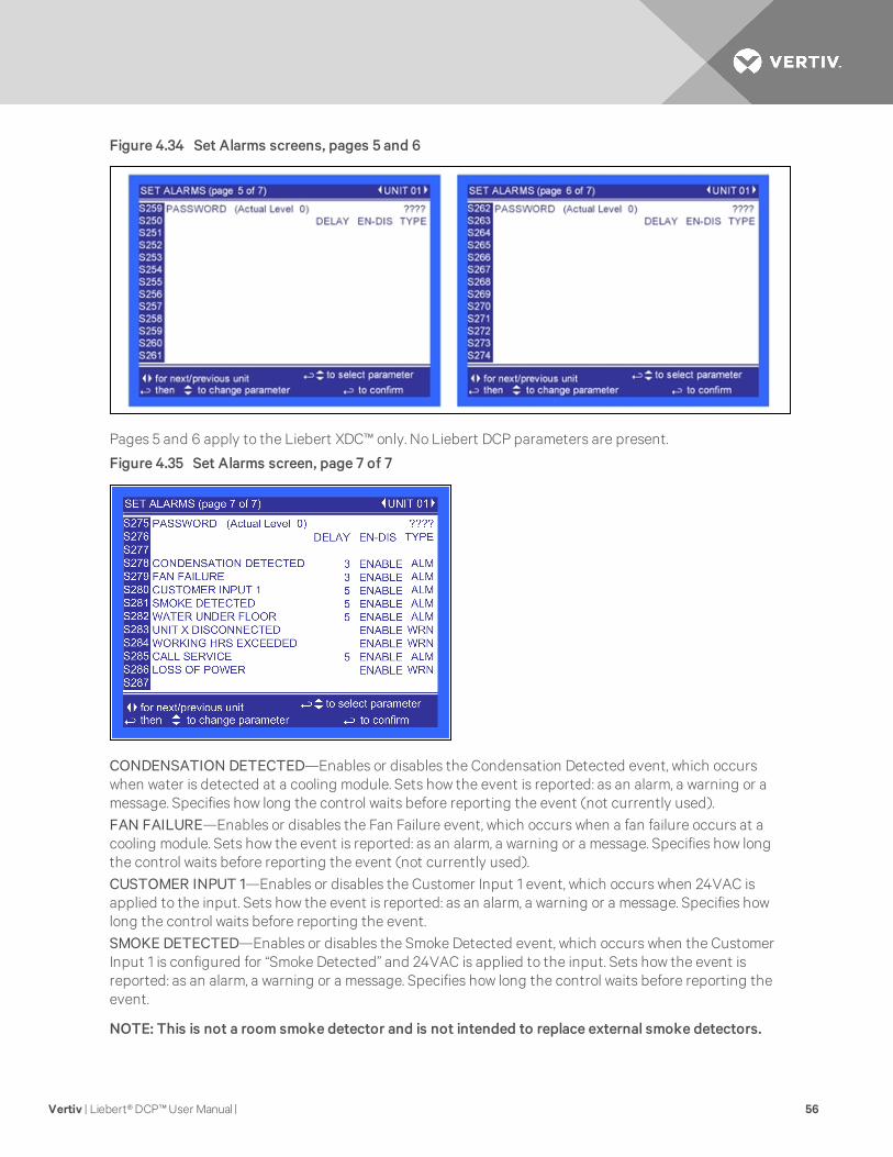
Figure 4.34 Set Alarms screens, pages 5 and 6
Pages 5 and 6 apply to the Liebert XDC™ only. No Liebert DCP parameters are present.
Figure 4.35 Set Alarms screen, page 7 of 7
CONDENSATION DETECTED—Enables or disables the Condensation Detected event, which occurswhen water is detected at a cooling module. Sets how the event is reported: as an alarm, a warning or amessage. Specifies how long the control waits before reporting the event (not currently used).FAN FAILURE—Enables or disables the Fan Failure event, which occurs when a fan failure occurs at acooling module. Sets how the event is reported: as an alarm, a warning or a message. Specifies how longthe control waits before reporting the event (not currently used).CUSTOMER INPUT 1—Enables or disables the Customer Input 1 event, which occurs when 24VAC isapplied to the input. Sets how the event is reported: as an alarm, a warning or a message. Specifies howlong the control waits before reporting the event.SMOKE DETECTED—Enables or disables the Smoke Detected event, which occurs when the CustomerInput 1 is configured for “Smoke Detected” and 24VAC is applied to the input. Sets how the event isreported: as an alarm, a warning or a message. Specifies how long the control waits before reporting theevent.
NOTE: This is not a room smoke detector and is not intended to replace external smoke detectors.
Vertiv | Liebert®DCP™User Manual | 56

WATER UNDER FLOOR—Enables or disables the Water Under Floor event, which occurs when theCustomer Input 1 is configured for “Water Under Floor” and 24VAC is applied to the input. Sets how theevent is reported: as an alarm, a warning or a message. Specifies how long the control waits beforereporting the event.
UNIT X DISCONNECTED—Not currently used.
WORKING HOURS EXCEEDED—Enables or disables the Working Hrs Exceeded event, which occurswhen a component has exceeded the user-specified limit. Sets how the event is reported: as an alarm, awarning or a message. Specifies how long the control waits before reporting the event.
CALL SERVICE—Enables or disables the Call Service event, which occurs when the Customer Input 1 isconfigured for “Call Service” and 24VAC is applied to the input. Sets how the event is reported: as analarm, a warning or a message. Specifies how long the control waits before reporting the event.
LOSS OF POWER—Enables or disables the Loss of Power event, which occurs when the unit is On andoperational and the 24VAC power to the control is lost. Sets how the event is reported: as an alarm, awarning or a message. Specifies how long the control waits before reporting the event.
Figure 4.36 Sensor Calibration/Setup screen, page 1 of 3
Temperature Sensor A—Adjusts the temperature reading from the actual remote CAN Temp Humiditysensor designated as Sensor A to compensate for any error of the sensor or to match other sensors in theroom.
Calibrated Temperature Sensor A—Displays the adjusted temperature value of the remote CAN TempHumidity sensor designated as Sensor A. This value is the actual sensor reading plus or minus the offsetTemperature Sensor A.
Humidity Sensor A—Adjusts the humidity reading from the actual remote CAN Temp Humidity sensordesignated as Sensor A to compensate for any error of the sensor or to match other sensors in the room.
Calibrated Humidity Sensor A—Displays the adjusted humidity value of the remote CAN Temp Humiditysensor designated as Sensor A. This value is the actual sensor reading plus or minus the offset HumiditySensor A.
Temperature Sensor B—Adjusts the temperature reading from the actual remote CAN Temp Humiditysensor designated as Sensor B to compensate for any error of the sensor or to match other sensors in theroom.
Calibrated Temperature Sensor B—Displays the adjusted temperature value of the remote CAN TempHumidity sensor designated as Sensor B. This value is the actual sensor reading plus or minus the offsetTemperature Sensor B.
Vertiv | Liebert®DCP™User Manual | 57

Humidity Sensor B—Adjusts the humidity reading from the actual remote sensor designated as Sensor Bto compensate for any error of the sensor or to match other sensors in the room.
Calibrated Humidity Sensor B—Displays the adjusted humidity value of the remote CAN Temp Humiditysensor designated as Sensor B. This value is the actual sensor reading plus or minus the offset HumiditySensor B.
Figure 4.37 Sensor Calibration/Setup screen, page 2 of 3
Supply Coolant Sensor—Adjusts the temperature reading from the actual supply coolant sensor tocompensate for any error of the sensor.Calibrated Supply Coolant Sensor—Displays the adjusted temperature value of the supply coolant sensor.This value is the actual sensor reading plus or minus the offset Supply Coolant Sensor.Supply Chilled Water Sensor—Adjusts the temperature reading from the actual supply chilled watersensor to compensate for any error of the sensor.Calibrated Chilled Water Sensor—Displays the adjusted temperature value of the supply chilled watersensor. This value is the actual sensor reading plus or minus the offset Supply Chilled Water Sensor.
Figure 4.38 Sensor Calibration/Setup screen, page 3 of 3
Supply Coolant Sensor 0%—Allows the sensor reading to be calibrated at the lowest reading of the sensor.This calibration changes the start point of the sensor reading.
Supply Coolant Sensor 100%—Allows the sensor reading to be calibrated at the highest reading of thesensor. This calibration changes the end point of the sensor reading.
Vertiv | Liebert®DCP™User Manual | 58

Figure 4.39 System/Network Setup screen—System, page 1 of 2
Number of Connected Units—Shows the number of displays connected. This is always 1.
Configuration Safe—Saves or loads configuration settings for the display that have been modified fromthe factory defaults to an internal file that can be downloaded/uploaded using the Liebert iCOM® ServiceTool. Selecting Save will write the settings to the internal storage file and selecting Load will write thesettings from the internal storage file to the application software. The internal file is updatedautomatically every 12 hours.
Network Safe—Saves or loads network settings for the display that have been modified from the factorydefaults to an internal file that can be downloaded/uploaded using the Liebert iCOM Service Tool.Selecting Save will write the settings to the internal storage file and selecting Load will write the settingsfrom the internal storage file to the application software.
SW Version—Contains the application software version loaded onto the Liebert iCOM display.
Figure 4.40 System/Network Setup screen—System, page 2 of 2
IP Address—Contains the network address of the display. This address must be unique on the network.The factory default is 192.168.254.003.
Netmask—Defines which part of the IP address is used for the network. The factory default is255.255.255.000.
Vertiv | Liebert®DCP™User Manual | 59

Gateway—A network point that acts as an entrance to another network. The factory default is0.000.000.000.
MAC—A unique hardware identifier for the Ethernet device. The following parameters (U2U Protocol, U2UAddress and U2U Group) are for displaying other networked Liebert DCP units. The Liebert DCP does notperform Teamwork Operations.
U2U Protocol—This is always set to GBP.
U2U Address—A unique identifier for each display on the network. Display addresses range from 33 to 64.Each display on the U2U network must have a different U2U address. Not currently used.
U2U Group—Used to create zones or groups within a U2U network. Once a group number is selected, thedisplay will see only other devices with the same group number. The group number can be changed toview other devices in different groups. Not currently used.
Bootloader Variables—Indicates the bootloader has changed since it was last loaded. This parametershould only be activated by an authorized service person.
Figure 4.41 System/Network Setup screen—Unit, page 1 of 2
Monitoring Address—Sets the address used by the Liebert IntelliSlot® cards. This is set to 3 at the factoryand should not be changed.
Unit Name—Identifies the unit from the local or remote display. This label will show at the top right ofevery screen that has monitoring or configuration of that unit
Configuration Safe—Saves or loads configuration settings for the control board that have been modifiedfrom the factory defaults to an internal file that can be downloaded / uploaded using the Liebert iCOM®Service Tool. Selecting “Save” will write the settings to the internal storage file and selecting “Load” willwrite the settings from the internal storage file to the application software. The internal file is updatedevery 12 hours automatically.
Network Safe—Saves or loads network settings for the control board that have been modified from thefactory defaults to an internal file that can be downloaded / uploaded using the Liebert iCOM ServiceTool. Selecting “Save” will write the settings to the internal storage file and selecting “Load” will write thesettings from the internal storage file to the application software.
SW Version—Contains the application software version loaded onto the Liebert iCOM.
Vertiv | Liebert®DCP™User Manual | 60

Figure 4.42 System/Network Setup screen—Unit, page 2 of 2
Monitoring Protocol—Selects the monitoring protocol. Velocity V4 is the factory default which will providecommunications to the Liebert IntelliSlot® housing. IGMnet will activate the 77/78 terminals forcommunication to the Liebert SiteLink(-E)®. Liebert Hironet™ is only used on Liebert HPM™ units.
IP Address—Contains the network address of the display. This address must be unique to every otherdevice on the network. The factory default is 192.168.254.003.
Netmask—Defines which part of the IP address is used for the network. The factory default is255.255.255.000.
Gateway—A gateway is a network point that acts as an entrance to another network. The factory defaultis 0.000.000.000.
MAC—The MAC address is a unique hardware identifier of the Ethernet device.
The following parameters (U2U Protocol, U2U Address and U2U Group) are for displaying other LiebertDCP units that are networked. The Liebert DCP does not perform Teamwork Operations.
U2U Protocol—Always set to GBP.
U2U Address—Unique identifier for each display on the network. Display addresses range from 1 to 32.Each display on the U2U network must have a different U2U address. Not currently used.
U2U Group—Creates zones or groups within a U2U network. Once a group number is selected the displaywill only see other devices with the same group number. The group number can be changed to view otherdevices in different groups. Not currently used.
Bootloader Variables—Indicates if there has been a change to the boot loader since it was last loaded.This parameter should only be activated by authorized service personnel.
Static RAM—Allows service personnel to clear and reboot the RAM of the control board. Only Emerson®
service personnel should perform this function.
Vertiv | Liebert®DCP™User Manual | 61

Figure 4.43 Options Setup screen, page 1 of 2
Autorestart Enabled—Restarts the unit after a power cycle when set to Yes. When this parameter is set toNo, the unit will not restart after a power cycle.
Single Unit Auto Restart—Sets a time delay for the unit to restart when the Auto Restart Enabled is set toYes. The delay begins once the boot process has completed. This parameter allows units to be staggeredOn to reduce the amount of simultaneous power consumption after a loss of power.
Unit Start Sequence Delay—Not currently used.
Control Delay Time—Not currently used.
Pump Start Time Delay—Sets a time delay to ensure that coolant begins flowing when the pump starts. Ifcoolant does not begin flowing before the user-set delay expires, the pump will be turned Off.
Pump Wait Time Delay—Sets the pump wait time delay to prevent the pump from continuing to run whencoolant is not flowing. If a pump is running normally and coolant flow is lost, the pump will stay On for thespecified time trying to re-establish coolant flow. If coolant flow resumes during the specified interval, thepump will continue operating. If the wait time expires and coolant flow has not resumed, the pump willshut down.
Pump Off Time Delay—Sets the length of time a pump will remain off when coolant flow is interrupted orstops. After the time delay has expired, the control will try to restart the pump.
Lead Pump—Sets which pump is the active pump. It can be set to PUMP 1 or PUMP 2. The control willoperate the respective pump unless a loss of flow condition occurs. On a LOSS OF FLOW condition, thecontrol will switch to the standby pump after the LOSS OF FLOW alarm time delay has elapsed and theLOSS OF FLOW alarm has been annunciated. The default is PUMP 1.
Pump Short Cycle Delay—Sets the time to lock Off the unit if it is unable to establish coolant flow withinthis set amount of time.
Vertiv | Liebert®DCP™User Manual | 62

Figure 4.44 Options Setup screen, page 2 of 2
Valve Start Open—Sets position of the valve when the unit starts.
Valve Start TD—Sets a time interval for the unit to complete startup and enter into normal operation.
3P Actuator Runtime—If Valve Control is selected for “Time,” then this parameter sets the travel time ofthe valve to determine the full open and closed position of the valve. This parameter is set at the factory,based on the valve manufacturer’s specifications.
3P Actuator Direction—Sets if the valve is a “Direct” or “Reverse” acting valve.
Unit Off Valve % Open—Sets the valve position when the unit is Off.
Figure 4.45 Module Setup screen, page 1 of 20—Applies to Liebert XD™ smart modules only
This screen selects the operation of an active alarm for each smart module. Each event can be enabled ordisabled and can be set to operate as an alarm, a warning or a message. The delay is the time the controlwaits before reporting the event.
• Alarm: Annunciates the buzzer, triggers a monitoring event, triggers the alarm relay andflashes the red LED on the display.
• Warning: Annunciates the buzzer, triggers a monitoring event, shows the event in the eventviewer/front display and flashes the red LED on the display.
• Message: Shows the event in the event viewer and on the front display.
Fan Control Type—Sets the fan control mode. Values can be OFF, ON, ON ALL and TEMP CNTL.
Vertiv | Liebert®DCP™User Manual | 63

Disable Local Button—Disables the push button on the front of the smart module. To disable the pushbutton, set the parameter to YES. To re-enable the push button, set the parameter to NO.
Flash LED at Module—Flashes the LED on the smart module when set to Yes.
Set Module Label—A four-character label consisting of two letters and two numerals. This is the standardnomenclature for Data Center Grid assignment of racks. Additionally, the module’s location can bedenoted with 10 characters, either letters or non-alphanumeric characters from a built-in list. Either orboth labels can be used and are entered using this screen.
Supply Air Temp Limit—Sets the high and low supply air temperature to from the module. An alarm willoccur if the temperature falls outside the limits.
Return Air Temp Limit—Sets the high and low return air temperature to from the module. An alarm willoccur if the temperature falls outside the limits.
Firmware Version—Displays the firmware version installed on the smart module.
Figure 4.46 Module Setup screen, page 1 of 20—Applies to Liebert XD™ smart modules only
Vertiv | Liebert®DCP™User Manual | 64

5 START THE LIEBERT DCP WITH LIEBERT ICOM®
5.1 Checklist for Liebert DCP Startup
NOTE: Before any action that could cause a disturbance in the Liebert DCP system’s cooling functionis begun, the facilitymanager MUST be informed. In addition, after the action is taken and the work isfinished, the facilitymanager MUST be informed
1. Verify that bypass flow controllers were installed (if applicable).
2. Check all isolation ball valves in the Liebert DCP and cooling module and verify that all areopen.
3. Check rotation of the Liebert DCP’s pumps.
4. Verify that air is being discharged into the cold aisle.
5. Confirm that the system has been properly filled with water (see Filling Instructions onpage 24).
6. Confirm that the remote temperature/humidity sensors provided have been installed inoptimal locations (see Remote Sensor Installation—Proper Placement on page 18)
The Liebert DCP system is now ready to be turned ON.
5.2 Starting the Liebert DCP with Liebert iCOM Controller
The Liebert DCP is started, stopped and controlled through the Liebert iCOM controller. Figure 4.1 onpage 31 shows the Liebert iCOM keypad.
1. Turn the Liebert DCP On with the user interface (I/O button). Allow the system to attempt tostart for at least 2 minutes.
If the Liebert DCP pump cannot maintain flow and continues to switch over due to startingdifficulties, refer to Troubleshooting on page 71.
2. Check flow switch functionality:
The Liebert DCP system should be On. If it is Off:
a. Turn the Liebert DCP On via user interface (I/O button).
If no “Loss of Flow” alarm is present—This suggests that there is flow. Test the flowswitch by closing the ball valve on either the suction line or discharge line to stop the flow.
This should prompt an alarm for “loss of flow on P1.” This alarm confirms that the switchhas opened on low flow.
If a “Loss of Flow” alarm is present—This suggests that there is no flow. Verify that this iscorrectly annunciated by checking for proper water charge (see Filling Instructions onpage 24.)
However, if there is flow, the flow switch could be faulty. Check the flow switch, makingsure that the electrical connections are properly connected.
Then check the flow switch electrically by making sure that the unit has 24VAC across it.
Vertiv | Liebert®DCP™User Manual | 65

Vertiv | Liebert®DCP™User Manual | 66
This page intentionally left blank.

6 ALARM DESCRIPTIONS AND SOLUTIONS
6.1 Alarm Descriptions
NOTE: Alarms must be acknowledged before they can be reset. To acknowledge or silence an alarm,press the ALARM key one time. This will silence the alarm; the red LEDwill remain illuminated until thealarm is reset.
CALL SERVICE—Activated when Customer Input 1 is configured for “Call Service” and 24VAC is appliedto the input. This alarm is reset when the 24VAC is removed.
CONDENSATION DETECTED (optional)—Activated when water is detected at a cooling module. A24VAC signal is applied to the condensation input on the control board using a pair of twisted wires or thealarm is sent via CANbus communication. When this alarm is active, the control will raise its fluid controlpoint by 4°F (2.2°C). This alarm will reset when the alarms is acknowledged and the signal stops beingsent from CANbus or condensation input. The alarm can also be reset by cycling the power. The mainpower must be cycled to remove the 4°F (2.2°C) offset (not currently used).
CONTROL VALVE FAILURE—Activated when the chilled water control valve has been commanded toopen or close by the control and no change is detected by the valve position signal. The alarm is resetwhen the main power is cycled.
CUSTOMER INPUT 1—Activated when a 24VAC signal is applied to the customer alarm input on thecontrol board. This alarm will reset when the 24VAC signal stops being sent from the customer alarminput. WATER UNDER FLOOR, SMOKE DETECTED, CALL SERVICE, and COMP LOCK PD are possibledesignations for this alarm; they are set with the Unit Code.
FAN FAILURE (optional)—Activated when a 24VAC signal is applied to the fan failure input on thecontrol board using a twisted pair of wires or the alarm is sent via CANbus communication. This alarm willreset when the alarms is acknowledged and the signal stops being sent from CANbus or fan failure input.The alarm can also be reset by cycling the power (not currently used).
HIGH CW TEMP—Activated when the Supply CW sensor reads the chilled water temperature above theuser-specified alarm setpoint. This alarm will reset when the reading from the fluid temperature sensordrops 5°F (2.8°C) below the user-specified setpoint and the alarm has been acknowledged.
HIGH DEW POINT—Activates when the calculated dew point at either Sensor A or B exceeds the user-specified alarm setpoint. The alarm will reset when the calculated room dew point from both Sensor A andSensor B is 2°F (1.1°C) below the setpoint and the alarm has been acknowledged.
HIGH COOLANT TEMP—Activated when the coolant temperature sensor reads the coolant temperatureabove the user-specified alarm setpoint. This alarm will reset when the reading from the coolanttemperature sensor drops 2°F (1.1°C) below the user-specified setpoint and the alarm has beenacknowledged.
HIGH TEMP SENSOR A—Activated when the reading from Sensor A is above the user-specified alarmsetpoint. The alarm will reset when the reading from Sensor A drops 2°F (1.1°C) below the setpoint and thealarm has been acknowledged.
HIGH TEMP SENSOR B—Activated when the reading from Sensor A is above the user-specified alarmsetpoint. The alarm will reset when the reading from Sensor A drops 2°F (1.1°C) below the setpoint and thealarm has been acknowledged.
LOSS OF FLOW PUMP 1—Activated when Pump 1 is commanded to run and the flow switch does notsense flow. After attempting to start Pump 1 three times, the Liebert DCP will automatically switch to theother pump to establish flow. This alarm will reset when flow has been established on Pump 1 and thealarm has been acknowledged.
Vertiv | Liebert®DCP™User Manual | 67
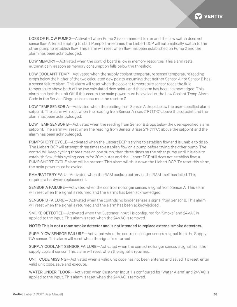
LOSS OF FLOW PUMP 2—Activated when Pump 2 is commanded to run and the flow switch does notsense flow. After attempting to start Pump 2 three times, the Liebert DCP will automatically switch to theother pump to establish flow. This alarm will reset when flow has been established on Pump 2 and thealarm has been acknowledged.
LOW MEMORY—Activated when the control board is low in memory resources. This alarm restsautomatically as soon as memory consumption falls below the threshold.
LOW COOLANT TEMP—Activated when the supply coolant temperature sensor temperature readingdrops below the higher of the two calculated dew points, assuming that neither Sensor A nor Sensor B hasa sensor failure alarm. This alarm will reset when the coolant temperature sensor reads the fluidtemperature above both of the two calculated dew points and the alarm has been acknowledged. Thisalarm can lock the unit Off. If this occurs, the main power must be cycled, or the Low Coolant Temp AlarmCode in the Service Diagnostics menu must be reset to 0.
LOW TEMP SENSOR A—Activated when the reading from Sensor A drops below the user-specified alarmsetpoint. The alarm will reset when the reading from Sensor A rises 2°F (1.1°C) above the setpoint and thealarm has been acknowledged.
LOW TEMP SENSOR B—Activated when the reading from Sensor B drops below the user-specified alarmsetpoint. The alarm will reset when the reading from Sensor B rises 2°F (1.1°C) above the setpoint and thealarm has been acknowledged.
PUMP SHORT CYCLE—Activated when the Liebert DCP is trying to establish flow and is unable to do so.The Liebert DCP will attempt three times to establish flow on a pump before trying the other pump. Thecontrol will keep cycling three times on one pump, then three times on the other pump until it is able toestablish flow. If this cycling occurs for 30 minutes and the Liebert DCP still does not establish flow, aPUMP SHORT CYCLE alarm will be present. This alarm will shut down the Liebert DCP. To reset this alarm,the main power must be cycled.
RAM/BATTERY FAIL—Activated when the RAM backup battery or the RAM itself has failed. Thisrequires a hardware replacement.
SENSOR A FAILURE—Activated when the controls no longer senses a signal from Sensor A. This alarmwill reset when the signal is returned and the alarms has been acknowledged.
SENSOR B FAILURE— Activated when the controls no longer senses a signal from Sensor B. This alarmwill reset when the signal is returned and the alarm has been acknowledged.
SMOKE DETECTED—Activated when the Customer Input 1 is configured for “Smoke” and 24VAC isapplied to the input. This alarm is reset when the 24VAC is removed.
NOTE: This is not a room smoke detector and is not intended to replace external smoke detectors.
SUPPLY CW SENSOR FAILURE—Activated when the control no longer senses a signal from the SupplyCW sensor. This alarm will reset when the signal is returned.
SUPPLY COOLANT SENSOR FAILURE—Activated when the control no longer senses a signal from thesupply coolant sensor. This alarm will reset when the signal is returned.
UNIT CODE MISSING—Activated when a valid unit code has not been entered and saved. To reset, entervalid unit code, save and execute.
WATER UNDER FLOOR—Activated when Customer Input 1 is configured for “Water Alarm” and 24VAC isapplied to the input. This alarm is reset when the 24VAC is removed.
Vertiv | Liebert®DCP™User Manual | 68

6.2 Warning Descriptions
LOSS OF POWER—Activated when the unit is On and operational and 24VAC power to the control is lost.This alarm will be emitted when power is restored to the control. The Liebert DCP will restart at a user-defined time delay after power is restored. Once activated, the alarm will remain activated for 30 minutes.
PUMP 1 HRS EXCEED—Activated when the Pump 1 Actual Hours exceeds the user-specified limit. Toreset, Actual Hours must be reset to 0.
PUMP 2 HRS EXCEED—Activated when the Pump 2 Actual Hours exceeds the user-specified limit. Toreset, Actual Hours must be reset to 0.
6.3 System Shutdown Causes
Unit Is Off By Coolant Sens Fail
The control has lost its signal from the coolant temperature sensor. The control has no way of controllingthe coolant temperature, so the unit is shut off. Main power (disconnect switch) must be turned Off, thenback On to clear this alarm.
Unit Is Off By High CW Temp
The entering chilled water temperature is too high to keep the pump(s) running normally. If a HIGH CWTEMP alarm occurs and the pump loses flow, then the Liebert DCP will go into a pre-chill mode. TheLiebert DCP can attempt to start again only if the entering chilled water temperature drops below theHIGH CW TEMP setpoint.
Unit Is Off By Pump Short Cycle
The control was unable to get a pump started upon startup or after a loss of flow. The control looks at theSHORT CYCLE time delay. If it cannot establish flow within that amount of time, the unit is shut down.Main power (disconnect switch) must be turned Off, then back On to clear this alarm.
Unit Is Off By Low Coolant Temp
The control was unable to raise the coolant temperature to the calculated fluid temperature control point.The unit is shut down because if the control cannot raise the coolant temperature to the calculatedcoolant temperature control point, water may condense on the coolant piping and receiving coils. Mainpower (disconnect switch) must be turned Off, then back On to clear this alarm.
Vertiv | Liebert®DCP™User Manual | 69

Vertiv | Liebert®DCP™User Manual | 70
This page intentionally left blank.

7 TROUBLESHOOTING
Symptom Possible Cause Check or Remedy
Pump will notenergize
No main power Check L1, L2 and L3 for rated voltage.
Loose electricalconnections Tighten connections.
Overloads tripped Allow pump to cool. Check amp draw.
Tripped circuit breaker Check circuit breaker to pump(s).
Incorrect phase wiring Check wiring phase.
Pump will notstart or run
No chilled water Check and verify that there is supply chilled water to the Liebert DCP.
Isolation valve(s) onpump suction and/ordischarge is closed.
Open all isolation valves completely during normal operation.
Supply chilled water is toohigh
Check and verify that the chilled water temperature setpoint is at 50°F (10°C) or lower and that there isflow on the chilled water side.
Liebert XDK™ coolingmodules are Off Check Liebert XDK cooling modules to make sure that they are On prior to starting the Liebert DCP.
Low CoolantTemperature(high dew point)
Check alarm(s) history on Liebert DCP. The Liebert DCP was operating below the dew point for asignificant amount of time. Check humidity in conditioned space, lower humidity if necessary to allowLiebert DCP to operate at a lower temperature. (Disconnect must be switched to Off then back On toallow Liebert DCP to reset itself).
Flow switch notfunctioning Check for defective switch or miswiring.
Not enough charge See Checklist for Liebert DCP Startup on page 65.
Pump will notstart
Chilled water valve notclosing completely.
Wait at least 10 minutes before calibrating. Access the Advanced Menu>Factory Settings>CalibrateActuator. Contact Liebert Services for assistance, 1-800-543-2778.
Pump noisy
Cavitation due to vapor inpump
Check for adequate charge in system, refer to the User's Manual. Checklist for Liebert DCP Startup onpage 65
Worn motor bearings Replace pump
Pump is rotating inreverse Check wiring phase.
Liebert DCP(Pump)suddenlystops
Low CoolantTemperature
Check humidity of the room along with the location of remote sensors. Make sure that the sensors are notin a cold area where there is insufficient air flow for accurate, representative readings. Chilled Watertemperature is too cold. Load is too light.
Loss of power When power is restored, the Liebert DCP will automatically restart.
Leak in system - loss ofcharge Check the entire system for leaks with a fluid sniffer. Repair as necessary.
Low Chilled WaterTemperature Alarm andLoss of Flow Pump XAlarm
Check supply chilled water temperature.
Supply Fluid SensorFailure Alarm
Check wiring.
Call service.
Pipe rattle Loose pipe connections Check pipe connections.
Table 7.1Troubleshooting the Liebert DCP
Vertiv | Liebert®DCP™User Manual | 71

Symptom Possible Cause Check or Remedy
Chilled watervalve notworking
Motor operates but valvewon't open Check linkage for adjustment and be sure that it is tight on the valve.
No 24 VAC power tomotor Check for 24 VAC between P52-1 and P52-4.
No signal from control Check 24 VAC at P22-1 (close) or P22-3 (open).
Motor not operatingUnplug P22 from the board. Jumper P22-5 to P52-4 for grounding, then jumper P22-1 to P52-1 to driveclose. Remove jumper to close and then jumper P22-3 to P52-1 to drive open. If motor fails to work,replace it.
Motorburnout
Check control panel forwelded contactorcontacts or weldedoverload contacts
Replace defective components.
Main 24VACfuse trips
Shorts or looseconnections Check the wiring connections of the 24 VAC circuit.
Faulty circuit board Replace the circuit board.
Roombecomes toowarm
Liebert DCP is Off Check status of the Liebert DCP at the user interface. Turn system On at I/O button if system is Off.
High dew point Check temperature and relative humidity (RH) of room. Lower RH setpoint if necessary to lower dewpoint. At normal room temperature of 68°F (20°C), the RH should be set to 50% or lower.
Liebert XDK™ coolingmodules are Off Check Liebert XDK cooling modules to make sure that they are On before starting the Liebert DCP.
Minimum roomtemperature setpoint istoo high
Check the setpoint in the User Setpoints menu (see Figure 4.19 on page 45).
Temperature/humiditysensors incorrectlyplaced
Place the sensor on the return air side of the primary air mover (e.g., Liebert DS™). Do not install thesensor near unsealed doors, windows or similar areas.
Table 7.1 Troubleshooting the Liebert DCP (continued)
Vertiv | Liebert®DCP™User Manual | 72

8 MAINTENANCE
NOTICE
Risk of leaking chilled water and drain lines. Can cause equipment and building damage.
Lines and joints must be inspected regularly. Improper installation, application and service practices canresult in water leakage from the unit. Water leakage can result in severe property damage and loss ofcritical data center equipment. Do not locate unit directly above any equipment that could sustain waterdamage. Emerson® recommends installing monitored leak detection equipment for the unit and itsfactory- and field-installed supply, return and drain lines.
The Liebert DCP system components require little maintenance when proper fluid levels are maintainedand proper startup and operation procedures are followed. The following task should be performed at theintervals stated:
• Clean or replace chilled water strainer annually. Adjust accordingly based on purity of chilledwater.
Vertiv | Liebert®DCP™User Manual | 73

Vertiv | Liebert®DCP™User Manual | 74
This page intentionally left blank.

9 SPECIFICATIONS
Models DCP200RA2BB0 DCP200RM2BB0
Cooling Capacity, Nominal
200kW / 57 Tons, 60Hz 200kW / 57 Tons, 50Hz
Each capacity is based on 45ºF (7ºC) entering water temperature and 114 gpm (26 m3/h) water flow rate.Capacity is reduced when glycol mixtures are used in place of 100% water.
Electrical Requirements
Input 460V/3/ph60Hz 380/415V/3ph/50Hz
Full Load Amps 7.3A 8.7A
WSA below 8 9
MFCB below 15 15
Dimensions, inches (mm)
Height – Unit Only 78 (1981)
Height – As Shipped 83 (2108)
Width 38 (965)
Depth 34 (864)
Weight, lb (kg)
Unit Only 931(423) 1105 (502)
Shipping Weight 1100 (499) 1275 (579)
Installed, with Fluid and Chilled Water 1148 (521) 1322 (600)
Pipe Connections
Fluid Supply to Cooling Module 2-5/8" OD, Cu
Fluid Return from Cooling Module 2-5/8" OD, Cu
Chilled Water Supply and Return 2-5/8" OD, Cu
Control Valve 2-way, 2" nominal; 35 PSIG close-off pressure rating;150 PSIG maximum allowable pressure
Pressure Drop – Chilled Water Side14.0 psig (97kPa, 0.97bar), with 114 gpm (26 m3/h) water flow rate,
control valve fully open
Temperature Rise – Chilled WaterSide at Rated Flow, °F (°C) 12.0 (6.7)
Number of Liebert Cooling Units Connected, Maximum
Liebert DCD35 10 @ 20 kW
Cabinet Exterior Finish Black, matte finish, heat-fused powder coat
Operating AmbientTemperature, Maximum, °F (°C) 86 (30)
WSA = Wire Sizing Amps (Minimum supply circuit ampacity)
MFCB = Maximum Fuse or Circuit Breaker Size
Table 8.1Liebert DCP200 specifications
NOTES
Vertiv | Liebert®DCP™User Manual | 75

Vertiv | Liebert®DCP™User Manual | 76
This page intentionally left blank.


VertivCo.com | Vertiv Headquarters, 1050 Dearborn Drive, Columbus, OH, 43085, USA
© 2017VertivCo. All rights reserved. Vertiv and the Vertiv logo are trademarks or registered trademarks of VertivCo. All other names and logos referred toare trade names, trademarks or registered trademarks of their respective owners. While everyprecaution has been taken to ensure accuracyandcompleteness herein, VertivCo. assumes no responsibility, and disclaims all liability, for damages resulting from use of this information or for anyerrors oromissions. Specifications are subject to change without notice.
SL-17310_REV7_10-17/590-1714-501A