LIBRETTO ALKON INSTALLATORE INGLESE - · PDF file4 General information 1.5 -SAFETY WARNING...
48
00332495 -4 th edition - 02/2009 INSTALLATION AND SERVICING MANUAL 18 R 24 R - 24 C 28 R - 28 C 35 R - 35 C ALKON English
Transcript of LIBRETTO ALKON INSTALLATORE INGLESE - · PDF file4 General information 1.5 -SAFETY WARNING...

00332495 -4th edition - 02/2009
INSTALLATIONANDSERVICING MANUAL
18 R24 R - 24 C28 R - 28 C35 R - 35 C
ALKON
English

Warning: this manual contains instructions to be used exclusively by theinstaller and/or a competent person in accordance with the current laws inforce.The end user MUST not make any alterations to the boiler.Failure to follow the instructions indicated in this manual, which is suppliedwith the boiler, could cause injury to persons, animals or damage to property.UNICAL shall not be held liable for any injury and/or damage.
CONTENTS
1 GENERAL INFORMATION ................................................................................................................................................................................. 31.1 Symbols used in this manual ....................................................................................................................................................................... 31.2 Correct use of the appliance ........................................................................................................................................................................ 31.3 Water treatment ............................................................................................................................................................................................. 31.4 Information to be handed over to the user ................................................................................................................................................... 31.5 Safety warnings ............................................................................................................................................................................................. 41.6 Data badge .................................................................................................................................................................................................... 51.7 General warnings .......................................................................................................................................................................................... 6
2 TECHNICAL FEATURES AND DIMENSIONS ................................................................................................................................................... 72.1 Technical features ......................................................................................................................................................................................... 72.2 Dimensions .................................................................................................................................................................................................... 72.3 Main components .......................................................................................................................................................................................... 82.4 Boiler water circuit ......................................................................................................................................................................................... 92.5 Performance data according to the Standard UNI 10348 ......................................................................................................................... 102.6 General features .......................................................................................................................................................................................... 10
3 INSTRUCTIONS FOR THE INSTALLER .......................................................................................................................................................... 113.1 General warnings ....................................................................................................................................................................................... 113.2 Standard codes for installation .................................................................................................................................................................. 123.3 Packaging ................................................................................................................................................................................................... 123.4 Boiler location ............................................................................................................................................................................................ 13
Dimensions for connecting the Alkon 28 to the external storage tank kit DSP120 ................................................................................ 143.5 Boiler installation ....................................................................................................................................................................................... 163.6 Gas connection .......................................................................................................................................................................................... 163.7 Central heating connections ...................................................................................................................................................................... 173.8 DHW connections ...................................................................................................................................................................................... 193.9 Examples of system pipework connections ............................................................................................................................................. 203.10 Condensate drain ....................................................................................................................................................................................... 213.11 Flue outlet installation ................................................................................................................................................................................ 223.12 Electrical connections ............................................................................................................................................................................... 22
General warnings ...................................................................................................................................................................................... 28Connection to mains supply 230V ............................................................................................................................................................ 28Access to the terminal block and external connections ........................................................................................................................ 28Outdoor sensor connection ..................................................................................................................................................................... 29ON-OFF digital room controller connection ............................................................................................................................................ 30Modulating RT/OT room controller connection ....................................................................................................................................... 30Layout of the electrical connection for zone control systems ............................................................................................................... 31
3.13 Wiring diagrams ........................................................................................................................................................................................ 32Functional flow wiring diagram for Alkon 24/28/35 C .............................................................................................................................. 32Functional flow wiring diagram for Alkon 18/24/28/35 R ........................................................................................................................ 33Jumper installation on the modulating board ........................................................................................................................................... 34
3.14 Filling the system ...................................................................................................................................................................................... 353.15 Initial lighting .............................................................................................................................................................................................. 363.16 Burner pressure adjustment .................................................................................................................................................................... 373.17 Variation of output range ........................................................................................................................................................................... 40
4 SERVICING SCHEDULE .................................................................................................................................................................................... 42Instructions for inspecting and servicing the appliance .................................................................................................................................. 42
5 FAULT CODES ................................................................................................................................................................................................... 45
6 CE CERTIFICATE ............................................................................................................................................................................................... 47

3
General information
1.1 -SYMBOLS USED IN THIS MANUAL
When reading this manual particular care has to be given to the parts marked with the followings symbols:
NOTE! Suggestions for theuser
WARNING! Indicates a potentiallydangerous situation for the product andthe environment
DANGER! Indicates seriousdanger for your personalsafety and for your life
1.2 -A CORRECT USE OF THE APPLIANCE
The ALKON appliance has been designed utilizing today’s heating technology and in compliance with thecurrent safety regulations.However, following an improper use, dangers could arise for the safety and life of the user or of otherpeople, or damage could be caused to the appliance or other objects.The appliance is designed to be used in pumped hot water central heating systems and for the productionof domestic hot water.Any other use of this appliance will be considered improper.UNICAL declines any responsibility for any damages or injuries caused by an improper use; in this casethe risk is completely at the user’s responsibility.In order to use the appliance according to the foreseen scopes it is necessary to carefully follow theinstructions indicated in this manual.
1.3 -WATER TREATMENT
• The hardness of the mains water supply conditions the frequency with which the DHW heat exchanger iscleaned.
• In hard water areas where the main water can exceed 15°f total hardness, a scale reducing device is recom-mended. The choice of this device has to be made taking into consideration the characteristics of the water.
• In order to improve the resistance to lime scale it is recommended to adjust the domestic hot water temperatureas near as possible to the one you really require.
• We recommend you to check the state of cleanliness of the domestic hot water heat exchanger at the end of thefirst year and subsequently, on the basis of the lime scale found, this period can be extended to two years.
The user has to be instructed on the use and operation of his heating system, in particular:• Hand over these instructions to the end user, together with any other literature regarding this appliance placed
inside the envelope contained in the packaging. The user has to keep these documents in a safe place inorder to always have them at hand for future reference.
• Inform the user on the importance of air vents and of the flue outlet system, stressing the fact that is absolutelyforbidden to make any alterations to the boiler.
• Inform the user how to check the system’s water pressure as well as informing him how to restore the correctpressure.
• Explain the function of time and temperature controls, thermostats, heating controls and radiators, to ensure thegreatest possible fuel economy.
• Remind the user that, in order to comply to the standards in force, it is necessary to inspect and service the boileraccording to the current codes of practice and according to the schedule indicated in this manual by themanufacturer.
• If the appliance is sold or transferred to another owner or if the present user moves home and leaves the applianceinstalled, ensure yourself that the manual always follows the appliance so that it can be consulted by the newowner and/or installer.
Failure to follow the instructions indicated in this guide, which is supplied with the boiler, could causeinjury to persons, animals or damage to property. The manufacturer shall not be held liable for any suchinjury and/or damage.
1.4 - INFORMATION TO BE HANDED OVER TO THE USER
1 GENERAL INFORMATION

4
General information
1.5 -SAFETY WARNING
WARNING!The installation, adjustment, and servicing of this appliance must be carried out by a competent personand installed in accordance with the current standards and regulations. Failure to correctly install thisappliance could cause injury to persons, animals or damage to property. The manufacturer shall not beheld liable for any injury and/or damage.
DANGER!Servicing or repairs of the appliance must be carried out by UNICAL authorised service technicians; UNICALrecommends drawing up a service contract. Bad or irregular servicing could compromise the safe operation ofthe appliance, and could cause injury to persons, animals or damage to property for which UNICAL shall not beheld liable.
Alterations to parts connected to the applianceDo not carry out any alterations to the following parts:- the boiler- to the gas, air, water supply pipes and electrical supply- to the flue pipe, safety relief valve and its drainage pipe- to the constructive components which influence the appliance’s safe operation
WARNING!When tightening or loosening the screw pipe connections, use only adequate fork spanners.The improper use and/or the use of inadequate equipment can cause damages (for example water or gas leakages).
WARNING!Indications for appliances operating with propane gasEnsure yourself that before installing the appliance the gas tank has been purged.For a correct purging of the tank contact the liquid gas supplier or a competent person who has been legallyauthorized.If the tank has not been correctly purged problems could occur during ignition.If this occurs contact the liquid gas tank’s supplier.
Smell of gasIf you smell gas follow these safety indications:• Do not turn on or off electrical switches• Do not smoke• Do not use the telephone• Close the mains gas tap• Open all windows and doors where the gas leakage has occurred• Contact the gas society or a company specialized in installing and servicing heating systems
Explosive and easily inflammable substancesDo not use or leave explosive or easily inflammable material (as for example: petrol, paint, paper) in the roomwhere the appliance has been installed.

5
General information
1.6 - DATA BADGE
LEGEND:1 = CE Surveillance notify body2 = Boiler type3 = Boiler model4 = Number of stars (Directive 92/42/CEE)5 = (S.N°) Serial number6 = P.I.N. code7 = Approved fluing configurations8 = (N0x) N0x class
A = Central Heating circuit features9 = (Pn) Nominal output10 = (Pcond) Condensing nominal output11 = (Qmax) Nominal heat input12 = (Adjusted Qn) Adjusted for nominal Heat input13 = (PMS) Max. pressure C.H. system14 = (T max) Max. C.H. temperature
B = Domestic Hot Water circuit features15 = (Qnw) Nominal heat input in D.H.W. mode (if different from Qn)16 = (D) Specific D.H.W. flow rate according to EN 625 - EN 13203-1
17 = (R factor) N° taps based on the quantity of water declared EN13203-1
18 = (F factor) N°stars based on the quality of water declaredEN 13203-1
19 = (PMW) Max. pressure D.H.W. system20 = (T max) Max. temperature D.H.W system
C = Electrical features21 = Electrical power supply22 = Consumption23 = Protection grade
D = Countries of destination24 = Direct and indirect country of destination25 = Gas family26 = Supply pressure
E = Factory setting27 = Adjusted for gas type X28 = Space for national brands
CE Marking- The CE marking documents that the boilers satisfy:- The essential requirements of the Directive regarding gas appliances (Directive
90/396/CEE)
- The essential requirements of the Directive regarding electromagnetic compatibility(Directive 89/336/CEE)
- The essential requirements of the Efficiency Directive (Directive 92/42/CEE)- The essential requirements of the low voltage Directive (Directive 73/23/CEE)
® 1
2
3
5
7 8
6
4
9
11
13
10
12
14
15
17
19
16
18
20
28
A
B
21 22
23
24 25 26
27
C D
E

6
General information
1.7 - GENERAL WARNINGS
This instruction manual is an integral and indispensable partof the product and must be retained by the user.
Please read carefully the instructions contained in this manualas they provide important indications regarding the safeinstallation, use and servicing of this appliance.
Keep this manual in a safe place for future reference.
The installation and servicing must be carried out in accordancewith the regulations in force according to the manufacturer’sinstructions and by legally competent authorized persons.
By a competent person, we imply a person who has a specifictechnical qualification in the field of components for centralheating systems for domestic use, domestic hot waterproduction and servicing. The person must have thequalifications foreseen by the current laws in force.
Bad or irregular servicing could compromise the safe operationof the appliance, and could cause injury to persons, animalsor damage to property. The manufacturer shall not be held liablefor any such injury and/or damage.
Before carrying out any cleaning or servicing turn off theelectrical supply to the boiler by means of the ON/OFF switchand/or by means of the appropriate shutdown devices.
Do not obstruct the inlet/outlet terminals.
In the event of failure and/or faulty functioning of the appliance,switch off the boiler. Do not attempt to make any repairs: contactqualified technicians.
Any repairs must be carried out solely by Unical authorizedtechnicians and using only or iginal spare par ts. Non-observance of the above requirement may jeopardize the safetyof the appliance.
To guarantee the efficiency and correct functioning of theappliance it is indispensable to have the boiler serviced annuallyby a qualified person.
If the boiler remains unused for long periods, ensure that anydangerous parts are rendered innocuous.
If the appliance is sold or transferred to another owner or if thepresent user moves home and leaves the appliance installed,ensure yourself that the manual always follows the applianceso that it can be consulted by the new owner and/or installer.
Only original accessories must be used for all appliancessupplied with optional extras or kits (including electrical ones).
This appliance must be used only for the purposes for which ithas been expressively designed. Any other use shall beconsidered incorrect and therefore dangerous.
7
Technical features and dimensions
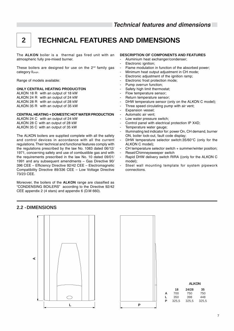
The ALKON boiler is a thermal gas fired unit with anatmospheric fully pre-mixed burner.
These boilers are designed for use on the 2nd family gascategory II2H3P.
Range of models available:
ONLY CENTRAL HEATING PRODUCITONALKON 18 R with an output of 18 kWALKON 24 R with an output of 24 kWALKON 28 R with an output of 28 kWALKON 35 R with an output of 35 kW
CENTRAL HEATING + DOMESTIC HOT WATER PRODUCTIONALKON 24 C with an output of 24 kWALKON 28 C with an output of 28 kWALKON 35 C with an output of 35 kW
The ALKON boilers are supplied complete with all the safetyand control devices in accordance with all the currentregulations. Their technical and functional features comply withthe regulations prescribed by the law No. 1083 dated 06/12/1971, concerning safety and use of combustible gas and withthe requirements prescribed in the law No. 10 dated 09/01/1991 and any subsequent amendments – Gas Directive 90/396 CEE – Efficiency Directive 92/42 CEE – ElectromagneticCompatibility Directive 89/336 CEE – Low Voltage Directive73/23 CEE.
Moreover, the boilers of the ALKON range are classified as“CONDENSING BOILERS” according to the Directive 92/42CEE appendix 2 (4 stars) and appendix 6 (D.M 660).
2 TECHNICAL FEATURES AND DIMENSIONS
2.2 -DIMENSIONS
DESCRIPTION OF COMPONENTS AND FEATURES- Aluminium heat exchanger/condenser;- Electronic ignition;- Flame modulation in function of the absorbed power;- Minimum heat output adjustment in CH mode;- Electronic adjustment of the ignition ramp;- Electronic frost protection mode;- Pump overrun function;- Safety high limit thermostat;- Flow temperature sensor;- Return temperature sensor;- DHW temperature sensor (only on the ALKON C model);- Three speed circulating pump with air vent;- Expansion vessel;- Automatic air vent;- Low water pressure switch;- Control panel with electrical protection IP X4D;- Temperature water gauge;- Illuminating led indicator for: power On, CH demand, burner
ON, boiler lock-out, fault code display;- DHW temperature selector switch:35/60°C (only for the
ALKON C model);- CH temperature selector switch + summer/winter position;- Reset/Chimneysweeper switch- Rapid DHW delivery switch RIRA ((only for the ALKON C
model);- Steel wall mounting template for system pipework
connections.
18 24/28 35A 700 750 750L 350 398 448P 325,5 325,5 325,5
L
A
P
ALKON
8
Technical features and dimensions
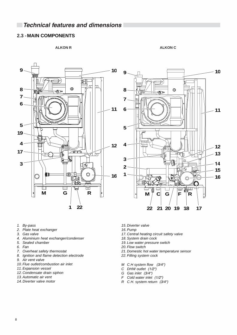
1. By-pass2. Plate heat exchanger3. Gas valve4. Aluminium heat exchanger/condenser5. Sealed chamber6. Fan7. Overheat safety thermostat8. Ignition and flame detection electrode9. Air vent valve10. Flue outlet/combustion air inlet11. Expansion vessel12. Condensate drain siphon13. Automatic air vent14. Diverter valve motor
2.3 -MAIN COMPONENTS
15. Diverter valve16. Pump17. Central heating circuit safety valve18. System drain cock19. Low water pressure switch20. Flow switch21. Domestic hot water temperature sensor22. Filling system cock
M C.H system flow (3/4“)C DHW outlet (1/2“)G Gas inlet (3/4“)F Cold water inlet (1/2“)R C.H. system return (3/4“)
ALKON R ALKON C
M G R
5
9
4
3
19
17
1
16
12
11
10
22
6
87
M C G F R
5
9
4
321
22 21 19 18 17
1615
1312
11
10
20
6
8
7

9
Technical features and dimensions
ALKON R 1. By-Pass2. Gas valve3. Central heating circuit safety valve4. Low water pressure switch5. Condensate drain siphon6. Flow temperature sensor7. Return temperature sensor8. Safety thermostat9. Aluminium heat exchanger/condenser10. Burner11. Air vent12. Premix13. Fan14. Sealed chamber15. Flue outlet/combustion air inlet16. Expansion vessel17. Pump18. Filling system cock
M C.H system flowG Gas inletR C.H. system return
M RG
1
3
2
4
6
75
8
9
10
13
11
16
17
14
15
12
F
18
ALKON C
2.4 -BOILER WATER CIRCUITS
M F RC G
1
2
3
45
6
87
9
10
13
16
20
2425
26
22
23
21
19
1817
14
15
12
11
27
1. By-Pass2. DHW temperature sensor3. Gas valve4. Flow temperature sensor5. Condensate drain siphon6. Return temperature sensor7. Safety thermostat8. Aluminium heat exchanger/condenser9. Burner10. Air vent11. Premix12. Fan13. Sealed chamber14. Flue outlet/combustion air inlet15. Expansion vessel16. Diverter valve motor17. Diverter valve18. Automatic air vent19. Low water pressure switch20. DHW plate heat exchanger21. Circulation pump22. Central heating circuit safety valve23. System drain cock24. Domestic hot water flow restrictor25. Flow switch26. Cold water filter27. Filling system cock
M C.H system flowC DHW outletG Gas inletF Cold water inletR C.H. system return

10
Technical features and dimensions
Appliance’s family gas category
Min. water flow rate in CH circuit (Dt 35°C)
Min. pressure in CH circuit
Max. pressure in CH circuit
Water content in primary circuit
Max operating temp. in CH mode
Min operating temp. in CH mode
Total volume CH expansion vessel
Total pre-loading expansion vessel
Max water content CH circuit (calculated for a max temp. of 90°C)
Min flow rate DHW circuit
Min. DHW inlet pressure
Max DHW inlet pressure
DHW specific flow rate (Dt 30°C)
DHW flow restrictor
DHW production in continuous operation with Dt 45 K
DHW production in continuous operation with Dt 40 K
DHW production in continuous operation with Dt 35 K
DHW production in continuous operation with Dt 30 K (*)
DHW production in continuous operation with Dt 25 K (*)
DHW adjustable temperature
Electrical supply /power consumption
Fuse rating
Maximum absorbed power
Electrical protection
Net weight
2.6 - GENERAL FEATURES
2.5 - PERFORMANCE DATA ACCORDING TO STANDARD UNI 10348For information regarding the adjustment of: INJECTORS - BURNER PRESSURES – DIAPHRAGMS – OUTPUTS – GAS CONSUMPTIONS please refer to theparagraph BURNER PRESSURE ADJUSTMENT.
Technical data registered with the appliance operating with natural gas (G20)
Heat output
Nominal heat input
Minimum heat input
Efficiency at full load (100%)
Required efficiency at full load (100%)
Efficiency at 30% part load
Required efficiency at part load (30%)
Condensing nominal heat input
Condensing minimum heat input
Condensing efficiency at nominal load (100%)
Condensing requested efficiency (100%)
Condensing efficiency at 30% part load
Condensing requested efficiency at part load (30%)
Number of stars (according to CEE 92/42)
Combustion efficiency at full load (100%)
Combustion efficiency at reduced load
Stand-by losses (max)
(*) Flue gas temperature tf-ta (max)
Flue gas mass flow rate (min-max)
Air excess
Condensate production max
CO at 0% of O2 (min - max)
N0x (value according to EN 297/A3 and EN 483)
N0x class
Flue losses with burner in operation (max)
Flue losses with burner off
(*) Room Temperature = 20°C
(*) mixed
l/minbarbarl°C°Clbarll/minbarbarl/min.l/min.l/min.l/min.l/min.l/min.l/min.°CV-HzA (F)WIPkg
ALKON 35 C II2H3P
2,73
0,5
3
3
80
30
10
1
185,7
2
0,5
6
15
14
9,82
11,1
12,6
14,7
17,7
35-60
230/50
4
150
X4D
46
35 R II2H3P
2,73
0,5
3
3
80
30
10
1
185,7
-
-
-
-
-
-
-
-
-
-
-
230/50
4
150
X4D
41,5
28 CII2H3P
2,21
0,5
3
2,5
80
30
8
1
148,6
2
0,5
6
12,5
12
8,69
9,8
11,2
13
15,6
35-60
230/50
4
143
X4D
37
28 R II2H3P
2,21
0,5
3
2,5
80
30
8
1
148,6
-
-
-
-
-
-
-
-
-
-
-
230/50
4
143
X4D
33,5
18 R II2H3P
1,31
0,5
3
2
80
30
6
1
111,4
-
-
-
-
-
-
-
-
-
-
-
230/50
4
130
X4D
32,5
35 C7,0 - 34,8
34,16,7
97,9996,07
103,2193,6035,17,56
100,9992,55107,1598,55
498,0598,270,0646,7
2,75-15,9626,84
5,914 - 120
38,25
1,950,494
kW
kW
kW
%
%
%
%
kW
kW
%
%
%
%
n.
%
%
%
°C
g/s
%
kg/h
mg/kWh
mg/kWh
%
%
ALKON 35 R7,0 - 34,8
34,16,7
97,9996,07
103,2193,6035,17,56
100,9992,55107,1598,55
498,0598,270,0646,7
2,75-15,9626,845,9
14 - 12038,2
51,95
0,494
28 R5,6 - 28
27,35,4
97,4995,87
103,7893,3128,656,08
102,3392,46107,7898,46
497,6898,280,1846
2,23-12,8426,844,7
13 - 10549,65
52,32
0,441
24 C4,3 - 23,8
23,04,1
96,5895,72101,193,0824,064,64
101,0992,38107,2298,38
497,3398,540,7555,2
1,58-10,4320,57
4,026 - 146
57,625
2,670,473
18 R3,4 - 17
16,53,2
97,2695,44
102,5392,6617,53,63
102,7492,24
107,0998,24
497,7798,170,5144,1
1,32-7,826,843,05
15 - 8046,13
52,23
0,948
28 C5,6 - 28
27,35,4
97,4995,87
103,7893,3128,656,08
102,3392,46107,7898,46
497,6898,280,1846
2,23-12,8426,844,7
13 - 10549,65
52,320,441
24 R4,3 - 23,8
23,04,1
96,5895,72101,193,0824,064,64
101,0992,38107,2298,38
497,3398,540,7555,2
1,58-10,4320,57
4,026 - 146
57,625
2,670,473
24 C II2H3P
1,67
0,5
3
2,2
80
30
8
1
148,6
2
0,5
6
10,9
12
7,2
8,1
9,2
10,8
12,9
35-60
230/50
4
150
X4D
36
24 R II2H3P
1,67
0,5
3
2,2
80
30
8
1
148,6
-
-
-
-
-
-
-
-
-
-
-
230/50
4
150
X4D
33

11
Instruction for the installer
3 INSTRUCTIONS FORTHE INSTALLER
3.1 - GENERAL WARNINGS
WARNING!This boiler has to be destined for the usefor which it has been expressively designedfor. Any other use shall be consideredimproper and therefore dangerous.This boiler is designed to heat water at atemperature inferior to boiling point at anatmospheric pressure.
WARNING!These appliances are exclusively designedto be installed inside adequate sitings.Therefore these appliances must not beinstalled and operated outdoors. An outdoorinstallation could cause malfunctioning andcould be dangerous. For externalinstallations, it is recommended to useappliances which are specifically designedand predisposed for this purpose.
Before installing the boiler the following pointshave to be carried out by a competent engineer:a) The whole system should be thoroughly
flushed in order to remove any residual dirtor grime which could compromise correctboiler operation.
b) Check that the boiler has been preset foroperating with the gas type available.This is verifiable via the indication on thepackaging and on the data badge;
c) Check that the chimney/flue pipe has anadequate draught, does not have anyconstrictions, and that no other appliance’sflue outlets have been fitted, unless thechimney is serving more than one heatingappliance, according to the specificstandards and regulations in force. Theconnection between the boiler and chimney/flue outlet can be made only after thisverification has been carried out.
WARNING!In rooms where aggressive vapours or dustis present the appliance must operateindependently from the air present in theboiler’s location room!
WARNING!The appliance must be installed by aqualified engineer, who complies to thetechnical-professional requirementsaccording to the law 46/90 and whom, underhis own responsibility, guarantees thecompliance of the standards according tothe latest regulations.
WARNING!The appliance must be installed only on avertical flat wall, made of non combustiblematerial.The appliance must be positioned so that atleast the minimum operational and servicingclearances are provided.
NOTE:The boiler must be connected to a heating systemwhich is compatible to its performance and output.

12
Instruction for the installer
3.3 - PACKAGING
The ALKON range of boilers are supplied fully assembled in astrong cardboard box.
After having unpacked the boiler check that it isintact and undamaged.
Keep the packaging material (cardboard box,plastic bags, polyester protection etc.) out ofthe reach of children as they can bedangerous.
UNICAL refuses all liability for injury to persons, animals ordamage to property deriving from not having respected theabove mentioned recommendations.
In the packaging, in addition to the boiler, you can also find thefollowing contents:- Service logbook- User’s instruction guide- This installation and servicing manual- Warranty- Nr. 2 spare parts request coupons- N° 2 wall plugs for fixing the boiler to the wall- Pipe kit- Wall mounting template
Note:DO NOT DISPOSE OF PACKAGING IN THEENVIRONMENT
The ALKON boiler is a thermal unit designed for use with thefamily gas category II2H3P.
The appliance must be installed in compliance to theinstructions contained in this manual.
The installation must be carried out by a competent qualifiedengineer, whom will assume the responsibility of complyingto all the local and/or national regulations published inthe official publications, as well as all the applicable codesof practice.
The installation must be carried in accordance to the codes ofpractice, the regulations and the requirements hereby indicated,which constitute an indicative list, but not a complete one, asthese continue to undergo developments.
National installation regulations:
Gas plants for domestic use fed by network distributionStandard UNI-CIG 7129
Gas plants for domestic use not fed by network distributionStandard UNI-CIG 7131Law dated 5.03.90 n°46Law dated 9.01.91 n°10
Other applicable statutory requirements:Law 1083/71 (ref. Standard UNI for the design, installation andmaintenance).Law 46/90 and D.P.R. 447/91Law 10/91 and D.P.R. 412/93 and subsequent amendmentsD.M 1.12.1975
Moreover, the boiler must be installed in accordance to all theregulations regarding the boiler room, and comply to thebuilding regulations and the prescriptions regarding centralheating plants in force in the country the boiler is installed. The appliance must be installed, commissioned and servicedaccording to the regulations in force. This is also valid for thehydraulic system, the flue outlet system and the boiler locationroom.
3.2 – STANDARD CODES FOR INSTALLATION
18 24 - 28 35A 435 484 535B 794 844 844C 414 414 414
ALKON
13
Instruction for the installer
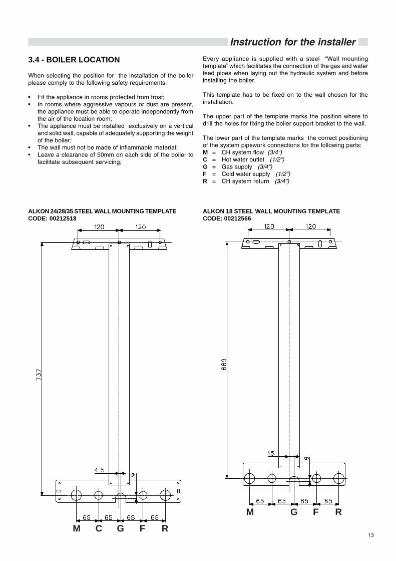
3.4 - BOILER LOCATION
When selecting the position for the installation of the boilerplease comply to the following safety requirements:
• Fit the appliance in rooms protected from frost;• In rooms where aggressive vapours or dust are present,
the appliance must be able to operate independently fromthe air of the location room;
• The appliance must be installed exclusively on a verticaland solid wall, capable of adequately supporting the weightof the boiler;
• The wall must not be made of inflammable material;• Leave a clearance of 50mm on each side of the boiler to
facilitate subsequent servicing;
Every appliance is supplied with a steel “Wall mountingtemplate” which facilitates the connection of the gas and waterfeed pipes when laying out the hydraulic system and beforeinstalling the boiler.
This template has to be fixed on to the wall chosen for theinstallation.
The upper part of the template marks the position where todrill the holes for fixing the boiler support bracket to the wall.
The lower part of the template marks the correct positioningof the system pipework connections for the following parts:M = CH system flow (3/4“)C = Hot water outlet (1/2“)G = Gas supply (3/4“)F = Cold water supply (1/2“)R = CH system return (3/4“)
ALKON 24/28/35 STEEL WALL MOUNTING TEMPLATECODE: 00212518
ALKON 18 STEEL WALL MOUNTING TEMPLATECODE: 00212566
M C G F R
M G F R

14
Instruction for the installer
a
b
c de
Note:The pipework for the condensate drain pointand pressure relief valve must be fitted underthe lower part of the boiler.
HOW TO POSTION THE WALL MOUNTING TEMPLATE ONTO THE WALL
70 mm (18 kW)50 mm (24-28 kW)37 mm (35 kW)
110
mm
a
b
c
de
POSITIONING OF THE SYSTEM PIPEWORKCONNECTIONS, CONDENSATE DRAIN AND PRESSURERELIEF VALVE
35 kW
M C G F R
4,5
165
65 65 65 65
172
Con
dens
ate
drai
n po
int
Pres
sure
relie
fva
lve
drai
n po
int
24/28 kW
M C G F R
10
111 170
65 65 65 65
Con
dens
ate
drai
n po
int
Pre
ssur
e re
lief
valv
e dr
ain
poin
t
18 kW
M G R15
Cond
ensa
tedr
ain
poin
t
Pres
sure
rel
ief
valv
e dr
ain
poin
t
76 54
130 130

15
Instruction for the installer
Dimensions for the connection of the ALKON R 18 to the external storage tank kit DSP 110
Mimp
RiFC
Svs
62,597,5
135 139
93795
2
117112
52
1948
120 120
M R
Rc Mc
62,5
Rimp
16
Instruction for the installer
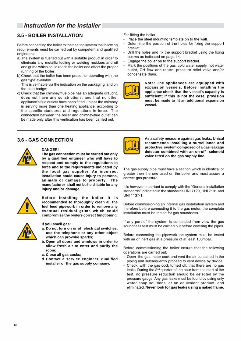
3.6 - GAS CONNECTION
DANGER!The gas connection must be carried out onlyby a qualified engineer who will have torespect and comply to the regulations inforce and to the requirements indicated bythe local gas supplier. An incorrectinstallation could cause injury to persons,animals or damage to property. Themanufacturer shall not be held liable for anyinjury and/or damage.
Before installing the boiler it isrecommended to thoroughly clean all thefuel feed pipework in order to remove anyeventual residual grime which couldcompromise the boilers correct functioning.
If you smell gas:a. Do not turn on or off electrical switches,
use the telephone or any other objectwhich can provoke sparks;
b. Open all doors and windows in order toallow fresh air to enter and purify theroom;
c. Close all gas cocks;d. Contact a service engineer, qualified
installer or the gas supply company.
3.5 - BOILER INSTALLATION
Before connecting the boiler to the heating system the followingrequirements must be carried out by competent and qualifiedengineers:a) The system is flushed out with a suitable product in order to
eliminate any metallic tooling or welding residues and oiland grime which could reach the boiler and affect the properrunning of the boiler;
b) Check that the boiler has been preset for operating with thegas type available.This is verifiable via the indication on the packaging and onthe data badge;
c) Check that the chimney/flue pipe has an adequate draught,does not have any constrictions, and that no otherappliance’s flue outlets have been fitted, unless the chimneyis serving more than one heating appliance, according tothe specific standards and regulations in force. Theconnection between the boiler and chimney/flue outlet canbe made only after this verification has been carried out.
For fitting the boiler:- Place the steel mounting template on to the wall.- Determine the position of the holes for fixing the support
bracket.- Drill the holes and fix the support bracket using the fixing
screws as indicated on page 14.- Engage the boiler on to the support bracket.- Mark the positions of the gas, cold water supply, hot water
outlet, CH flow and return, pressure relief valve and/orcondensate drain.
Note: The appliances are equipped withexpansion vessels. Before installing theappliance check that the vessel’s capacity issufficient; if this is not the case, provisionmust be made to fit an additional expansionvessel.
As a safety measure against gas leaks, Unicalrecommends installing a surveillance andprotective system composed of a gas leakagedetector combined with an on-off selenoidvalve fitted on the gas supply line.
The gas supply pipe must have a section which is identical orgreater then the one used on the boiler and must assure acorrect gas pressure.
It is however important to comply with the “General installationstandards” indicated in the standards UNI 7129, UNI 7131 andUNI 1137-1.
Before commissioning an internal gas distribution system andtherefore before connecting it to the gas meter, the completeinstallation must be tested for gas soundness.
If any part of the system is concealed from view the gassoundness test must be carried out before covering the pipes.
Before connecting the pipework the system must be testedwith air or inert gas at a pressure of at least 100mbar.
Before commissioning the boiler ensure that the followingoperations are carried out:- Open the gas meter cock and vent the air contained in the
piping and subsequently proceed to vent device by device.- Check, with the gas cock turned off, that there are no gas
leaks. During the 2nd quarter of the hour from the start of thetest, no pressure reduction should be detected by thepressure gauge. Any gas leaks must be found by using onlywater soap solutions, or an equivalent product, andeliminated. Never look for gas leaks using a naked flame.

17
Instruction for the installer
By-Pass CLOSEDrotate the screw in aclockwise direction
By-Pass OPENrotate the screw in aanti-clockwise direction
Alkon CBy-pass adjustment
clockwise
anti-clockwise
By-PassCLOSED
Alkon RBy-pass adjustment
By-PassOPEN
3.7 - CENTRAL HEATING CONNECTIONS
WARNING!Before installing the boiler we recommendthat the system is flushed out with a suitableproduct in order to eliminate any metallictooling or welding residues, oil and grimewhich could reach the boiler and affect theproper running of the boiler.
Do not use any solvents for flushing out thesystem as they could damage the systemand/or its components.
Non-observance of these instructions couldcause injury to persons, animals or damageto property. The manufacturer shall not beheld liable for any such injury and/ordamage.
The CH flow and return circuits have to be connected to theboiler via the respective connections ¾” M and R as indicatedon page 14.
When determining the size of the CH circuit pipes it is essentialto bear in mind the pressure losses induced by the radiators,any eventual thermostatic radiator valves, lockshield valvesand by the system’s layout.
The routing of the piping has to be laid down taking all thenecessary precautions in order to avoid air locks and to facilitatethe continuous purging of the system.
Ensure yourself that the system’s piping isnot used as earth clamps for the electricalor telephonic system. They are absolutelyunsuitable for this use. In a short time thiscould cause serious damage to the piping,boiler and radiators.
The boiler is fitted with an automatic BY-PASS (differential valvewith a flow rate of about 150 l/h) which always ensures aminimum water flow rate to the heat exchanger even if, forexample, all the thermostatic valves fitted on the heating systemare closed.It is possible to adjust the by-pass by acting on the adjustmentscrews.
Pressure relief valve drain pipeIn correspondence to the heating pressure relief valve provisionshould be made to install a discharge pipe with a funnel and asiphon which lead to an adequate drainage. The drainage hasto be controllable by sight.
WARNING!If this precaution is not taken it could leadto injury to persons, animals or damage toproperty.The manufacturer shall not be held liable forany such injury and/or damage.

18
Instruction for the installer
BOILER CIRCULATION PUMPGraph – Water flow rate/ available head for installation– ALKON 28 kW
BOILER CIRCULATION PUMPGraph - Water flow rate/ available head for installation – ALKON 18 kW
Flow rate (Q) l/h
Ava
ilabl
e he
ad (m
c.a.
)
0 50
0,5
100 150 200 250 300 350 400 450 500 550 600 650 700 750 800 850 900 950 1000 1050 1100 1150 1200 1250 1300 1350 1400
1,0
1,5
2,0
2,5
3,0
3,5
4,0
4,5
5,0
5,5
6,0
6,5
7,0
0 50
0,5
100 150 200 250 300 350 400 450 500 550 600 650 700 750 800 850 900 950 1000 1050 1100 1150 1200 1250 1300 1350 1400
1,0
1,5
2,0
2,5
3,0
3,5
4,0
4,5
5,0
5,5
6,0
6,5
7,0
0 50
0,5
100 150 200 250 300 350 400 450 500 550 600 650 700 750 800 850 900 950 1000 1050 1100 1150 1200 1250 1300 1350 1400
1,0
1,5
2,0
2,5
3,0
3,5
4,0
4,5
5,0
5,5
6,0
6,5
7,0
BOILER CIRCULATION PUMPGraph – Water flow rate/ available head for installation– ALKON 24 kW
Flow rate (Q) l/h
Ava
ilabl
e he
ad (m
c.a.
)
Flow rate (Q) l/h
Ava
ilabl
e he
ad (m
c.a.
)

19
Instruction for the installer
3.8 - DOMESTIC HOT WATER CONNECTIONS(Model “C”)
WARNING!Before connecting the boiler to the watermains supply ensure that the system isflushed out with a suitable product in orderto eliminate any metallic tooling or weldingresidues, oil and grime which could reachthe boiler and affect the proper running ofthe boiler.
Non-observance of these instructions couldcause injury to persons, animals or damageto property. The manufacturer shall not beheld liable for any such injury and/ordamage.
The hot water distribution and domestic hot water supplypipework must be connected to their respective ½ boiler pipeconnections C and F as indicated on page 14.
Ava
ilabl
e he
ad (m
c.a.
)
Flow rate (Q) l/h
BOILER CIRCULATION PUMPGraph – Water flow rate/ available head for installation– ALKON 35 kW
The pressure in the system must be between 1and 3 bar (if the pressure is higher fit a reducingpressure valve).
WARNING!The hardness of the mains water supplyconditions the frequency with which the DHWheat exchanger is cleaned.In hard water areas the opportunity of fittingan adequate scale reducing device fordomestic purposes for treating the mainswater supply to the boiler, in compliance tothe DM n°443 dated 21/12/90, should be takeninto consideration.Where water hardness exceeds 15°f, a scalereducing device is always recommended.
Ensure yourself that the system’s water andcentral heating piping are not used as earthclamps for the electrical or telephonic system.They are absolutely unsuitable for this use.In a short time this could cause serious damageto the piping, boiler and radiators.
0 50
0,5
100 150 200 250 300 350 400 450 500 550 600 650 700 750 800 850 900 950 1000 1050 1100 1150 1200 1250 1300 1350 1400
1,0
1,5
2,0
2,5
3,0
3,5
4,0
4,5
5,0
5,5
6,0
6,5
7,0
20
Instruction for the installer
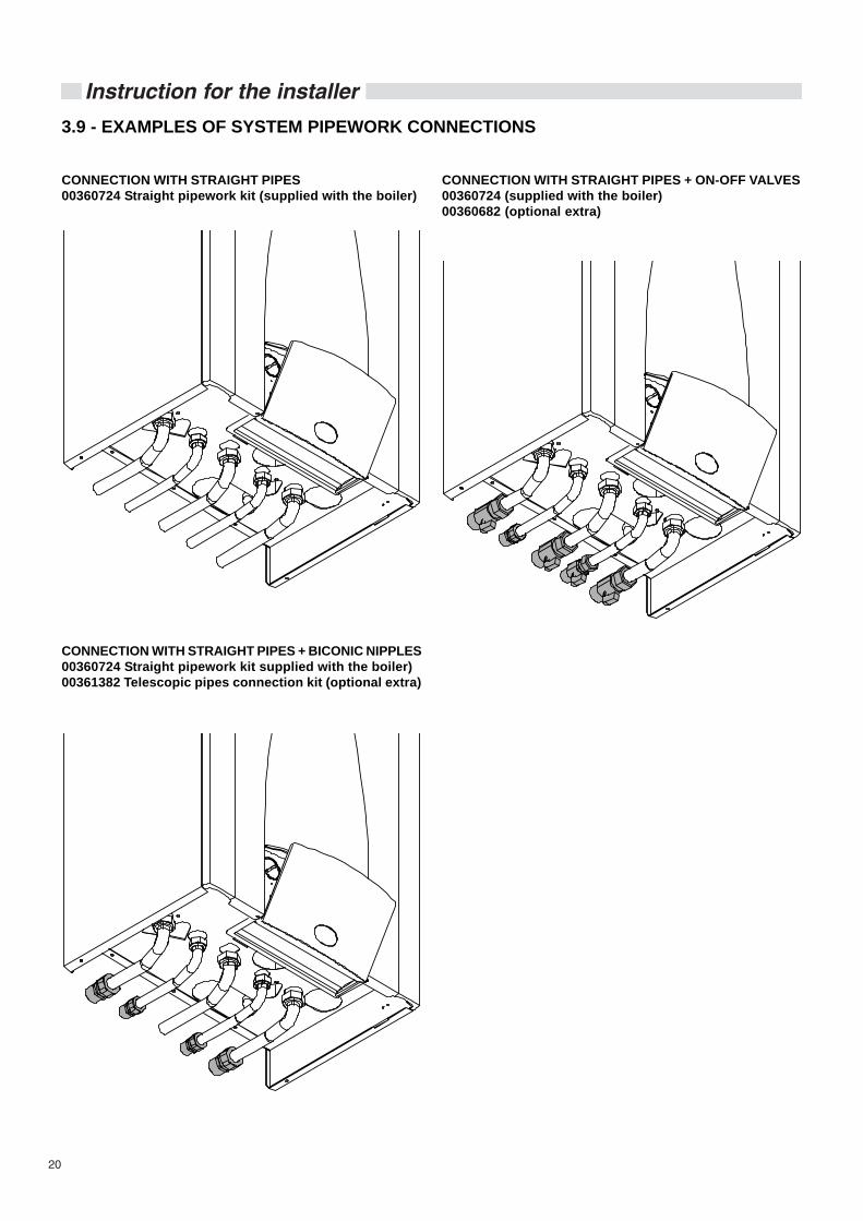
3.9 - EXAMPLES OF SYSTEM PIPEWORK CONNECTIONS
CONNECTION WITH STRAIGHT PIPES00360724 Straight pipework kit (supplied with the boiler)
CONNECTION WITH STRAIGHT PIPES + BICONIC NIPPLES00360724 Straight pipework kit supplied with the boiler)00361382 Telescopic pipes connection kit (optional extra)
CONNECTION WITH STRAIGHT PIPES + ON-OFF VALVES00360724 (supplied with the boiler)00360682 (optional extra)

21
Instruction for the installer
3.10 - CONDENSATE DRAIN
During the combustion process the boiler produces condensatewhich, through the “A” pipe, flows into the siphon.The condensate which forms inside the boiler has to be routedinto an adequate drain by means of the pipe “B”.
DANGER!Before commissioning the appliance fill thesiphon and check the correct drainage of thecondensate.If the appliance is used with the condensatedrain siphon empty there could be dangerof intoxication resulting from the escape offlue gasses.
The connection between the appliance and the sewage systemmust be carried out in compliance with the specific referencestandards, and in particular:- prevent the end user utilizing the condensate produced;- a siphon must be fitted (supplied with the boiler);- there must be no bottlenecks;- the connection must be made just under the bottom part of
the boiler;- it must be installed so as to avoid freezing of the liquid when
the boiler is operating and prevent the eventual pressuriza-tion of the sewage system;
- consent the correct downflow of the appliance’s liquid di-scharges;
- it must be made with one of the following materials whichare resistant to condensate:- Grès, according to the Standards DIN 1230-1 and 6, EN
295-1 or 2 or 3;- Glass (boron silicate);- Polyvinyl chloride (PVC) , according to DIN V 19534-1 and
2, and DIN 19538;- Polyethylene (PE) DH type, according to DIN 19535-1 and
2 and DIN 19537-1 and 2;- Polypropylene (PP) and copolymer styrene (ABS) accor-
ding to DIN V 19561;- Polyesterific resin (GF-UP), according to DIN 19565-1;- Stainless steel.
Condensate inletcoming from theflue outlet
Condensateoutlet, pipeto connectto thesewagesystem
Condensate inletcoming from theheat exchanger
A
B

22
Instruction for the installer
3.11 - FLUE OUTLET INSTALLATIONThe flue system must be installed in accordance with thelocal and national Standards (refer to Standard UNI-CIG7129, point 4 and UNI-CIG point 5).
We recommend using only original UNICALflue outlet systems.Damages caused by installation errors and fornon-observance of the instructions given bythe same manufacturer will invalidate all thesupplier’s contractual or extra contractualresponsibilities.
If the boiler has to be replaced ALWAYS replace the flueoutlet system.
The boiler has been approved for the following flueconfigurations:
C13 oiler designed for connection to horizontal inlet and out-let terminals, which admit fresh air to the burner and di-scharge the products of combustion to the outside throu-gh concentric or twin ducts.The minimum distance between the inlet air duct and theflue outlet duct must be of 250 mm and both terminalsmust be positioned within a 500 mm square section.
C33 Boiler designed for connection to vertical inlet and outletterminals, which admit fresh air to the burner and dischar-ge the products of combustion to the outside throughconcentric or twin ducts.The minimum distance between the air inlet duct and theflue gas outlet duct must be of 250 mm and moreoverboth terminals must be positioned within a 500 mmsquare area.
C43 Boiler designed for connection to collective flue systemsincluding two ducts, one for the air inlet and the other forthe discharge of products of combustion through con-centric or twin ducts.
C53 Boiler with separate air inlet and products outlet. Theseducts can discharge into areas with different pressure.The two terminals must not be fitted on to twoopposite walls.
C83 Boiler designed for connection to a terminal for the in-take of combustion air and to an individual or collectivechimney for the discharge of the products of combustion.The chimney must comply to the current regulations.
B23 Boiler designed to be connected to an open flue whichwill terminate vertically through the roof. The combustionair is withdrawn directly from the room where the boileris installed.WARNING: for this type of connection the room mustcomply with the same installation regulations validfor open chimney boilers.The chimney must comply to the current regulations.
aaaaaa
aaaaaaaaaaaaaaaaaaaaaaaaaaaaaaaaaa
Type C63Boiler designed for connection to a combustion air inlet andflue products discharge system approved and sold separately.

23
Instruction for the installer
Type C33The maximum allowable length of the vertical concentric pipesis of 8,5 metres, apart from the terminal Ø 80/125. For eachelbow added the maximum length permitted has to be reducedby 1 metre.
Type C13The minimum allowable length of the horizontal concentricpipes is of 0,75 metres.The maximum allowable length of the horizontal concentricpipes is of 3,5 metres. For each elbow added the maximumlength permitted has to be reduced by 1 metre.
HORIZONTAL FLUE OUTLET WITH CONCENTRIC DUCTS Ø 60/100 mm
Important: the outlet/inlet flue has tohave a minimum inclination of 3%towards the top in the outlet direction,so as to enable the collection of anycondensate formed in the boiler.
pendenza 3%
KIT5740C00360674
KIT5820C
00361334
218
118
37 (35 kW)50 (24-28 kW)70 (18 kW) KIT5810C
KIT5800C
24
Instruction for the installer
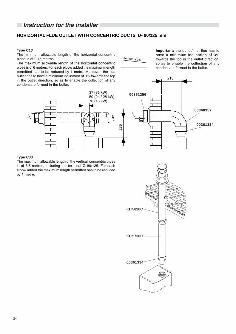
Type C13The minimum allowable length of the horizontal concentricpipes is of 0,75 metres.The maximum allowable length of the horizontal concentricpipes is of 6 metres. For each elbow added the maximum lengthpermitted has to be reduced by 1 metre. Moreover, the flueoutlet has to have a minimum inclination of 3% towards the topin the outlet direction, so as to enable the collection of anycondensate formed in the boiler.
Type C33The maximum allowable length of the vertical concentric pipesis of 8,5 metres, including the terminal Ø 80/125. For eachelbow added the maximum length permitted has to be reducedby 1 metre.
HORIZONTAL FLUE OUTLET WITH CONCENTRIC DUCTS D• 80/125 mm
Important: the outlet/inlet flue has tohave a minimum inclination of 3%towards the top in the outlet direction,so as to enable the collection of anycondensate formed in the boiler.
pendenza 3%
218
235
37 (35 kW)50 (24 / 28 kW)70 (18 kW)
KIT5730C
KIT5820C
00361334
00360357
00361256
00361334

25
Instruction for the installer
FLUE OUTLET WITH SEPARATE DUCTS D• 80 mm
It is not permitted to position the twoterminals on opposite walls.
The maximum pressure loss permitted, independently from thetype of installation, must not exceed the value of 100 Pa.
00361435
KIT5770C
KIT5780C
TSC0130CoppureTSC0150C
120
Ø 80
218
222
(r=
D)
205
(r=
½D
) 37 (35 kW)50 (24 / 28 kW)70 (18 kW)

26
Instruction for the installer
FLUE CONFIGURATION Ø 80 mm
The maximum allowed pressure drop, apart from theinstallation type, cannot be higher than 100 Pa.
Example N.2
Intake of primary air and flue outlet from two external perimeterwalls.It is not permitted to position the two terminals on oppositewalls.
Example N.1
Intake of primary air from the perimeterwall and flue outlet from the roof.
The maximum pressure drop of 100 Pa includes the losses created by:
1 adapter from 1 x Ø60/100 mm to 2 x Ø80mm2 wide radius curves +1 exhaust terminal +1 air intake terminal
00361435 TSC0130CTSC0150C
KIT 5750C KIT 5760C
KIT5750C - KIT 5760C KIT 5780C
KIT 5770C
TSC0130CTSC0150C
KIT5750C - KIT 5760C
KIT5790C
00361435
KIT 5750C KIT 5760C
TSC0130CTSC0150C
KIT 5770C
CALCULATION OF THE PRESSURE LOSSESOF THE COMBUSTION AIR INLET/PRODUCTSOUTLET DUCTS
When calculating the pressure losses bear in mind thefollowing parameters:
- For the twin flue pipe system’s adaptor, the pressure loss isof 4 Pa;
- For narrow radius 90° bend Ø 80 (R=½ D), the pressureloss is of 14 Pa;
- For each large radius 90° bend Ø 80 (R=½ D), the pressureloss is of 4 Pa;
- For each metre of Ø 80 flue pipe the pressure loss is of 1 Pain the combustion air inlet;
- For each metre of Ø 80 flue pipe the pressure loss is of 1,5Pa in the combustion product outlet;
- For the Ø 80 L=1 horizontal combustion air inlet terminalthe pressure loss is of 3,5 Pa;
- For the Ø 80 L=1 horizontal combustion products outletterminal the pressure loss is of 5,5 Pa;
- For the vertical flue outlet duct Ø 80 L=1 the pressure lossis of 8 Pa.
Note: These values refer to flue systems madewith original UNICAL non flexible and smoothpipes.

27
Instruction for the installerFLUE CONFIGURATION Ø 60 mmThe maximum allowed pressure drop, apart from theinstallation type, cannot be higher than 60 Pa.
CALCULATION OF THE PRESSURE LOSSESOF THE COMBUSTION AIR INLET/PRODUCTSOUTLET DUCTS
When calculating the pressure losses bear in mind thefollowing parameters:- For the twin flue pipe system’s adaptor, the pressure loss is
of 4 Pa;- For reducer M Ø80 / F Ø60 the pressure drop is 6 Pa in
evacuation and 3 Pa in suction- For reducer F Ø80 / M Ø60 the pressure drop is 6 Pa in
evacuation and 3 Pa in suction- For each large radius 90° bend Ø 60 (R=D), the pressure
loss is of 4 Pa;- For each metre of Ø 60 flue pipe the pressure loss is of 3 Pa
in the combustion air inlet;For each metre of Ø 60 flue pipe the pressure loss is of 5 Pain the combustion product outlet;
- For the Ø 60 L=1 horizontal combustion air inlet terminalthe pressure loss is of 6 Pa;
- For the Ø 60 L=1 horizontal combustion products outletterminal the pressure loss is of 10 Pa;
- For the vertical flue outlet duct Ø 80 L=1 the pressure lossis of 8 Pa
Note: These values refer to flue systems madewith original UNICAL non flexible and smoothpipes.
00361435
00360360
00360351
00360352
00360353 00360355
00360353 00360354
00360351
00361435
00360360
0036035100360355 00360352
00360353
00360356
KIT5790C
The maximum pressure drop of 60 Pa includes the losses created by:
1 adapter from 1 x Ø60/100 mm to 2 x Ø80mm2 wide radius curves +1 exhaust terminal +1 air intake terminal +2 reducer M Ø80 / F Ø60
Example N.1
Intake of primary air from the perimeterwall and flue outlet from the roof.
Example N.2
Intake of primary air and flue outlet from two external perimeterwalls.It is not permitted to position the two terminals on oppositewalls.

28
Instruction for the installer
3.12 - ELECTRICAL CONNECTIONS
The appliance’s electrical safety is guaranteed only when thesame appliance has been correctly earthed in compliance withthe regulations in force. The gas and water feeding pipes andthe CH system pipes cannot be used as ground plates.
Ensure that the above safety electrical requirements subsist;in case of doubt, ask for a professionally qualified technicianto check the appliance’s electrical system.
UNICAL refuses responsibility for any damages arising fromfailure to earth the boiler correctly.
It is necessary that a qualified technician verifies that theelectrical system is adequate to the appliance’s maximumabsorbed power, indicated on the data plate, verifying inparticular that the section of the system’s cables is suitable tothe appliance’s maximum absorbed power.
For the appliance’s general electrical supply the use ofadaptors, multiple sockets and/or extension cords is strictlyforbidden.
The use of any power supplied equipment implies theobservance of several fundamental rules, such as:- Do not touch the appliance with any wet part of your body
and/or barefooted;- Do not pull the supply cables;- Do not expose the boiler to sunlight, rain, etc., unless it is
explicitly foreseen;- Do not permit children or inexpert people to use the ap-
pliance.
Connection to mains supply 230V
The boiler is provided complete with a 1,5 m long, mains supplycable, with a cross section area of 3x0,75 mm2.
The boiler’s electrical connections are shown in the sectionnamed “WIRING DIAGRAMS” (paragraph 3.13 pages 31 and32)
A mains supply of 230 V – 50 Hz is required. The wiring to theboiler must be in accordance with the current CEI regulations.
DANGER!The electrical connections must be carriedout only by a qualified engineer.Before carrying out the connections or anyother operation on the electrical parts,always switch off and disconnect theelectricity supply and ensure yourself thatit cannot be accidentally turned on.
Note: It is necessary to fit a double pole switchon the electrical supply line, having a 3 mmcontact separation in both poles, in an easyaccessible position so as to ensure quick and safeservicing.
The replacement of the supply cable as to becarried out by a qualified authorized UNICALengineer, using only original spare parts. Thenon-observance of the above couldcompromise the appliance’s safety.
Access to the electrical terminal block and externalconnections
DANGER!Switch off and disconnect the electricitysupply before carrying out any operationson the electrical parts.
- Remove the front panel.- To gain direct access to the connection areas remove the 4
screws “A” and remove the cover “B”.
Y1Y2
1L 2N 1 2 3 4 5 6 73 4
View of the terminal board after having removed the frontcover
29
Instruction for the installer
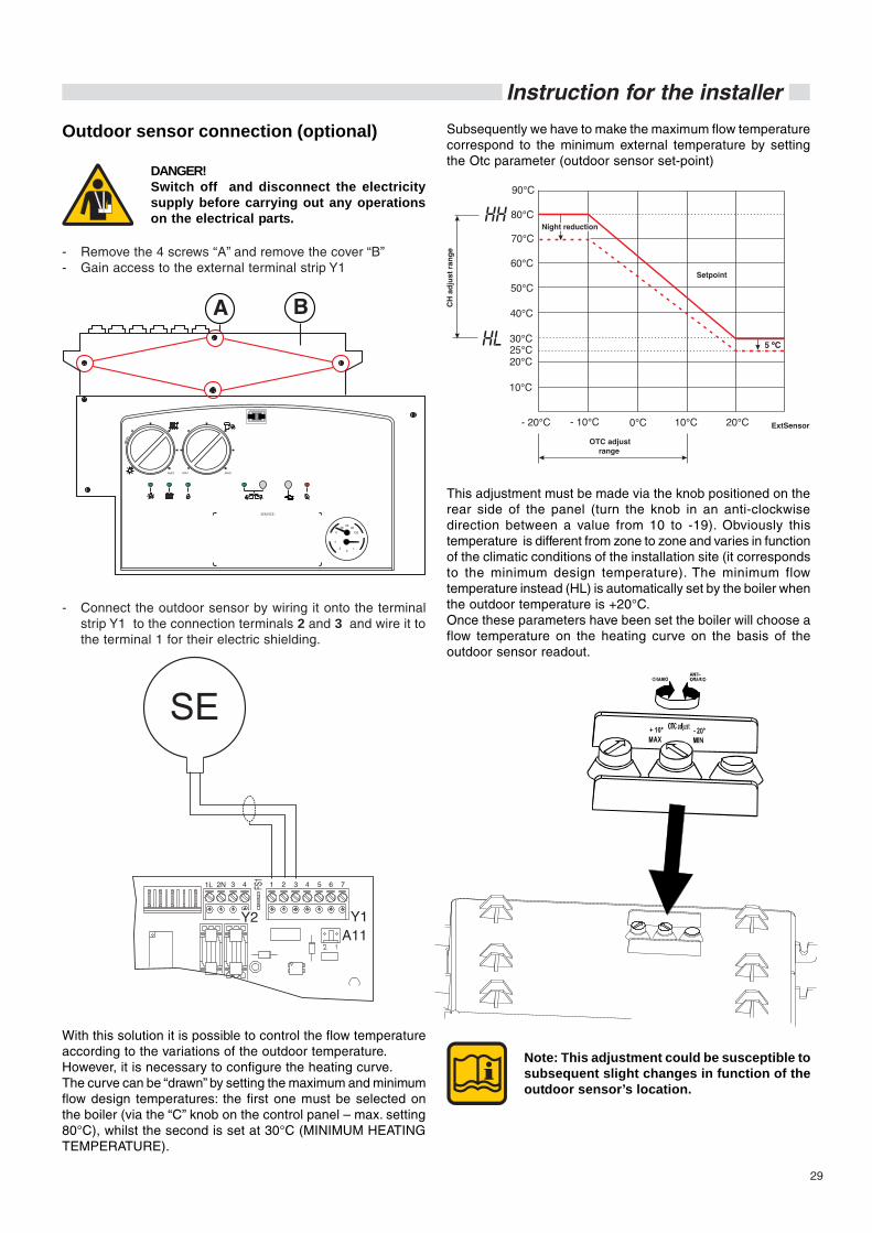
- Remove the 4 screws “A” and remove the cover “B”- Gain access to the external terminal strip Y1
Outdoor sensor connection (optional)
With this solution it is possible to control the flow temperatureaccording to the variations of the outdoor temperature.However, it is necessary to configure the heating curve.The curve can be “drawn” by setting the maximum and minimumflow design temperatures: the first one must be selected onthe boiler (via the “C” knob on the control panel – max. setting80°C), whilst the second is set at 30°C (MINIMUM HEATINGTEMPERATURE).
- Connect the outdoor sensor by wiring it onto the terminalstrip Y1 to the connection terminals 2 and 3 and wire it tothe terminal 1 for their electric shielding.
This adjustment must be made via the knob positioned on therear side of the panel (turn the knob in an anti-clockwisedirection between a value from 10 to -19). Obviously thistemperature is different from zone to zone and varies in functionof the climatic conditions of the installation site (it correspondsto the minimum design temperature). The minimum flowtemperature instead (HL) is automatically set by the boiler whenthe outdoor temperature is +20°C.Once these parameters have been set the boiler will choose aflow temperature on the heating curve on the basis of theoutdoor sensor readout.
DANGER!Switch off and disconnect the electricitysupply before carrying out any operationson the electrical parts.
Subsequently we have to make the maximum flow temperaturecorrespond to the minimum external temperature by settingthe Otc parameter (outdoor sensor set-point)
Note: This adjustment could be susceptible tosubsequent slight changes in function of theoutdoor sensor’s location.
30
Instruction for the installer
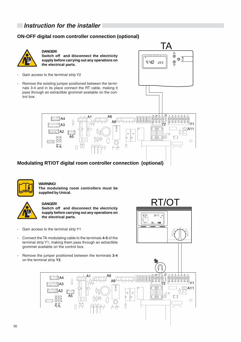
ON-OFF digital room controller connection (optional)
- Gain access to the terminal strip Y2
- Remove the existing jumper positioned between the termi-nals 3-4 and in its place connect the RT cable, making itpass through an extractible grommet available on the con-trol box.
DANGER!Switch off and disconnect the electricitysupply before carrying out any operations onthe electrical parts.
A4
A3
A2A5
A1 A6A8
Y1Y2
1L 2N 1 2 3 4 5 6 7
A11
3 4
TA
Modulating RT/OT digital room controller connection (optional)
- Gain access to the terminal strip Y1
- Connect the TA modulating cable to the terminals 4-5 of theterminal strip Y1, making them pass through an extractiblegrommet available on the control box.
- Remove the jumper positioned between the terminals 3-4on the terminal strip Y2.
DANGER!Switch off and disconnect the electricitysupply before carrying out any operations onthe electrical parts.
A4
A3
A2A5
A1 A6A8
Y1Y2
1L 2N 1 2 3 4 5 6 7
A11
123
3 4
10
2 3
24
18 6
12
RT/OT
WARNING!The modulating room controllers must besupplied by Unical.

31
Instruction for the installer
Layout of the electrical connections for zone control systems
Note: The terminal connections 3 and 4 in-dicated in the diagram refer to thevalve’s internal limit stop, when thesame valve is in the “low tempera-ture” position.
The microswitch on the 3-way valve closes whilst the roomthermostat is demanding heat when the diverter valvereaches the “low temperature” position and sends therequest to the boiler.
The 3-way valve has to use the limit switch contact in orderto simulate this type of request.
When the thermostat’s contact (On-Off) is closed, the 3-way valve opens the high temperature zone and closesthe low temperature zone (controlled by the digital roomcontroller “Regolafacile”).
With the thermostat’s contact (On-Off) open, the 3-wayvalve deviates towards the low temperature zone (thetemperature value can be adjusted with the digital roomcontroller).
M3
L
N
TA
4
LT zone HT zoneFlow
Return
External voltage line
To the terminals 3 and 4 on the Y2 connector
M3
LT zone HT zoneFlow
Return
External voltage line
L
N
TA
4
To the terminals 3 and 4 on the Y2 connector
M3
Low temperature zone High temperature zone
Boiler flow
Boiler return
Y1Y2
1L 2N 1 2 3 4 5 6 73 4
10
2 3
24
18 6
12
Digital room controller(low temperaturezone controller)
External voltage line
L
N
Room thermostat(high temperaturezone controller)
ONOFF
4

32
Instruction for the installer
3.13 - WIRING DIAGRAMS
FUNCTIONAL FLOW WIRING DIAGRAM ALKON 24/28/35 C
A1...A11 = Service connectorsDK = Minimum water pressure switchE.ACC/RIL = Ignition/detection electrodeFL = Minimum flow switchMVD = Diverting valve motorP = Circulating pumpSR = CH flow sensorSRR = CH return sensorSS = DHW sensor
TL = Limit thermostatVG = Gas valveVM = Modulating fanY1 = Connector: Outdoor sensor- modulating room
thermostatY2 = Connector: Line voltage - On/Off room thermostat
(230 V)
A4 A1
A3
A5
A2
A6 A8Y2X3 Y1
A11
A9
VM
123456
BLACK
GREEN
BLUEORANGE
LIGHT BLUE
BROWN
WHITE
YELLOW/GREEN
RED
YE
LLO
W/G
RE
EN
LIGHT BLUE
BROWN
VG
TRASF.ACC.
LIG
HT
BLU
E
LIG
HT
BLU
E
BR
OW
N
BR
OW
N
TL
FL
SS
SRR
SR
DK
BROWNWHITE
REDRED
GREENGREEN
WHITEWHITE
WHITE
BROWN
LIG
HT
BL
UE
LIG
HT
BL
UE
P
MDV
230 V - 50 HzTo the generalbipolar switch(installer)
LIG
HT
BLU
EB
RO
WN
BLA
CK
YE
LLO
W/G
RE
EN
E.ACC./RIL.
BLA
CK
33
Instruction for the installer
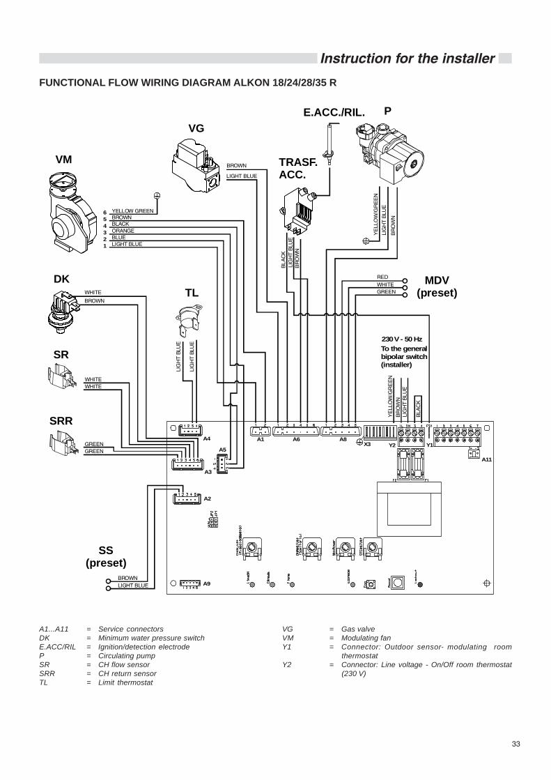
FUNCTIONAL FLOW WIRING DIAGRAM ALKON 18/24/28/35 R
A1...A11 = Service connectorsDK = Minimum water pressure switchE.ACC/RIL = Ignition/detection electrodeP = Circulating pumpSR = CH flow sensorSRR = CH return sensorTL = Limit thermostat
VG = Gas valveVM = Modulating fanY1 = Connector: Outdoor sensor- modulating room
thermostatY2 = Connector: Line voltage - On/Off room thermostat
(230 V)
A4 A1
A3
A5
A2
A6 A8Y2X3 Y1
A11
A9
VM
123456
BLACK
GREEN
BLUEORANGE
LIGHT BLUE
BROWN
WHITE
YELLOW GREEN
RED
YE
LLO
W/G
RE
EN
LIGHT BLUE
BROWN
VG
LIG
HT
BLU
E
LIG
HT
BLU
E
BR
OW
N
BR
OW
N
TL
SRR
SR
DK
BROWNLIGHT BLUE
GREENGREEN
WHITEWHITE
WHITE
BROWN
LIG
HT
BLU
E
LIG
HT
BLU
E
P
LIG
HT
BLU
EB
RO
WN
BLA
CK
YE
LLO
W/G
RE
EN
SS(preset)
MDV(preset)
TRASF.ACC.
E.ACC./RIL.
BL
AC
K
230 V - 50 HzTo the generalbipolar switch(installer)
34
Instruction for the installer
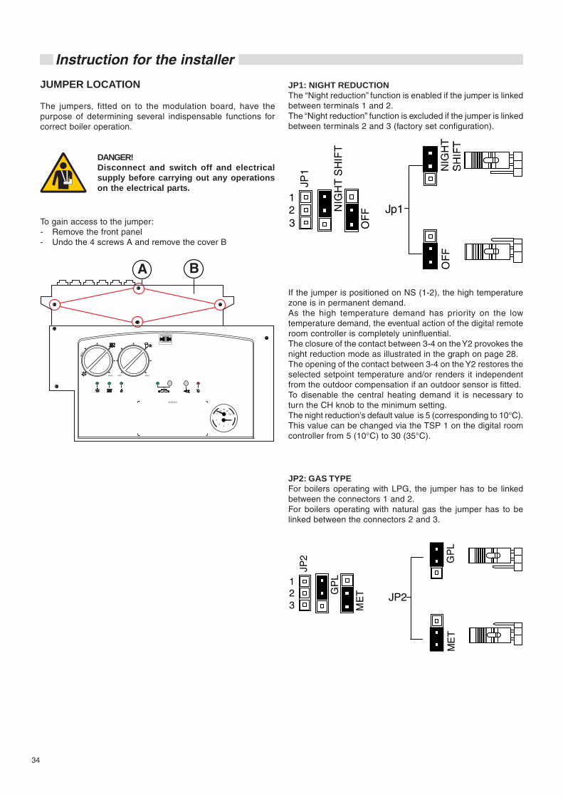
JUMPER LOCATION
The jumpers, fitted on to the modulation board, have thepurpose of determining several indispensable functions forcorrect boiler operation.
JP2: GAS TYPEFor boilers operating with LPG, the jumper has to be linkedbetween the connectors 1 and 2.For boilers operating with natural gas the jumper has to belinked between the connectors 2 and 3.
JP1: NIGHT REDUCTIONThe “Night reduction” function is enabled if the jumper is linkedbetween terminals 1 and 2.The “Night reduction” function is excluded if the jumper is linkedbetween terminals 2 and 3 (factory set configuration).
DANGER!Disconnect and switch off and electricalsupply before carrying out any operationson the electrical parts.
To gain access to the jumper:- Remove the front panel- Undo the 4 screws A and remove the cover B
If the jumper is positioned on NS (1-2), the high temperaturezone is in permanent demand.As the high temperature demand has priority on the lowtemperature demand, the eventual action of the digital remoteroom controller is completely uninfluential.The closure of the contact between 3-4 on the Y2 provokes thenight reduction mode as illustrated in the graph on page 28.The opening of the contact between 3-4 on the Y2 restores theselected setpoint temperature and/or renders it independentfrom the outdoor compensation if an outdoor sensor is fitted.To disenable the central heating demand it is necessary toturn the CH knob to the minimum setting.The night reduction’s default value is 5 (corresponding to 10°C).This value can be changed via the TSP 1 on the digital roomcontroller from 5 (10°C) to 30 (35°C).
OF
F
123
JP1
Jp1
OF
FNIG
HT
SH
IFT
JP2
GP
L
ME
TGP
L
ME
T
123
JP2
35
Instruction for the installer
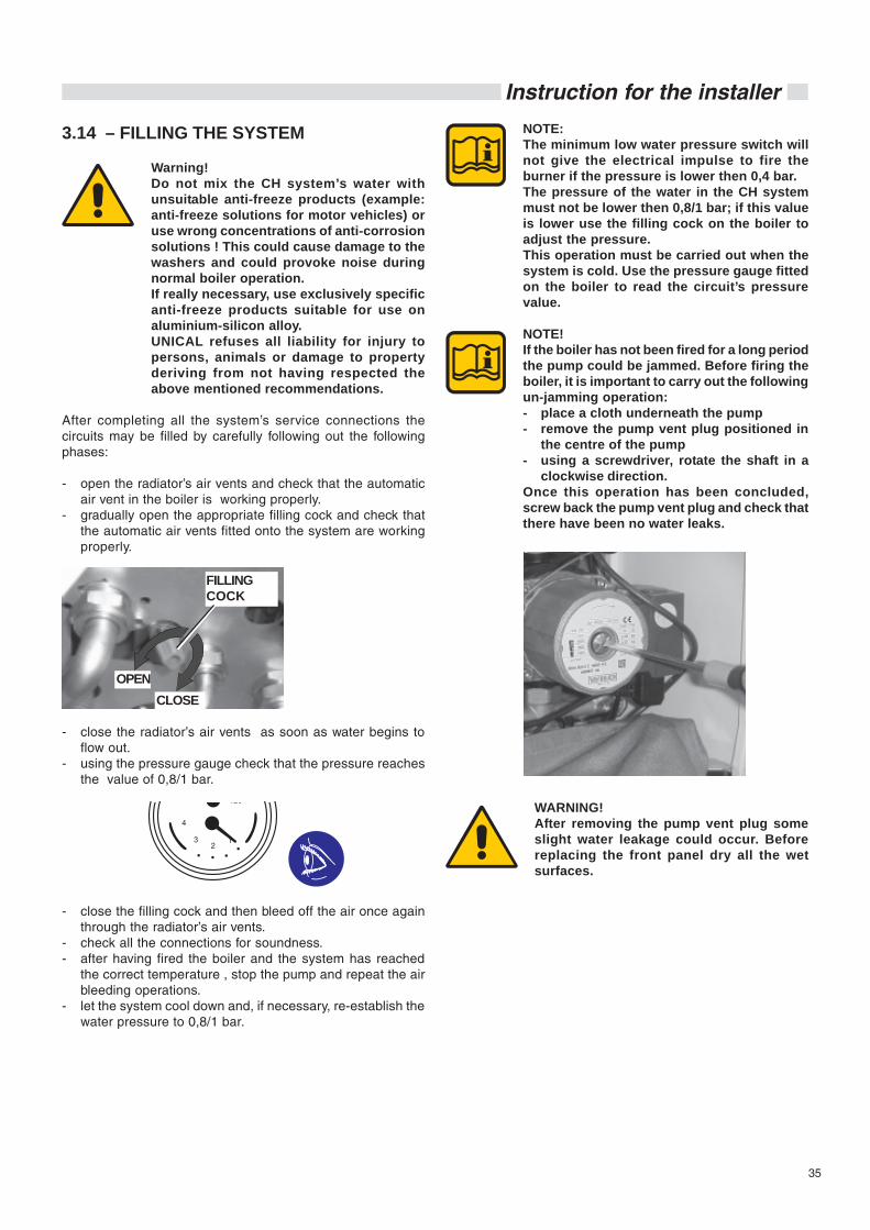
3.14 – FILLING THE SYSTEM
Warning!Do not mix the CH system’s water withunsuitable anti-freeze products (example:anti-freeze solutions for motor vehicles) oruse wrong concentrations of anti-corrosionsolutions ! This could cause damage to thewashers and could provoke noise duringnormal boiler operation.If really necessary, use exclusively specificanti-freeze products suitable for use onaluminium-silicon alloy.UNICAL refuses all liability for injury topersons, animals or damage to propertyderiving from not having respected theabove mentioned recommendations.
After completing all the system’s service connections thecircuits may be filled by carefully following out the followingphases:
- open the radiator’s air vents and check that the automaticair vent in the boiler is working properly.
- gradually open the appropriate filling cock and check thatthe automatic air vents fitted onto the system are workingproperly.
NOTE:The minimum low water pressure switch willnot give the electrical impulse to fire theburner if the pressure is lower then 0,4 bar.The pressure of the water in the CH systemmust not be lower then 0,8/1 bar; if this valueis lower use the filling cock on the boiler toadjust the pressure.This operation must be carried out when thesystem is cold. Use the pressure gauge fittedon the boiler to read the circuit’s pressurevalue.
NOTE!If the boiler has not been fired for a long periodthe pump could be jammed. Before firing theboiler, it is important to carry out the followingun-jamming operation:- place a cloth underneath the pump- remove the pump vent plug positioned in
the centre of the pump- using a screwdriver, rotate the shaft in a
clockwise direction.Once this operation has been concluded,screw back the pump vent plug and check thatthere have been no water leaks.
WARNING!After removing the pump vent plug someslight water leakage could occur. Beforereplacing the front panel dry all the wetsurfaces.
- close the radiator’s air vents as soon as water begins toflow out.
- using the pressure gauge check that the pressure reachesthe value of 0,8/1 bar.
- close the filling cock and then bleed off the air once againthrough the radiator’s air vents.
- check all the connections for soundness.- after having fired the boiler and the system has reached
the correct temperature , stop the pump and repeat the airbleeding operations.
- let the system cool down and, if necessary, re-establish thewater pressure to 0,8/1 bar.
FILLINGCOCK
OPENCLOSE

36
Instruction for the installer
3.15 INITIAL LIGHTING
PRELIMIARY CHECKS
The first ignition must be carried out by aqualified technician. Failure to do so couldcause injury to persons, animals or damageto property. UNICAL shall not be held liablefor any injury and/or damage.
Before lighting the boiler check that:
- the boiler installation has been carried out in accordancewith the specific Standards UNI 7129 and 7131 for the gaspart and the Standards CEI 64-8 and 64-9for the electricalpart;
- the combustion air inlet and the discharge of the productsof combustion occur in the correct way in accordance tothe specific Standards in force (UNI 7129/7131);
- the gas supply system is correctly dimensioned for the boi-ler’s output;
- the boiler’s electrical supply is 230 V - 50 Hz;
- the system has been filled with water (pressure registeredon the gauge 0,8/1 bar with pump not running);
- any of the system’s on-off valves are open;
- the mains supply gas corresponds to the one which theboiler has been calibrated for: otherwise convert the boilerto use the available gas (refer to section: “GAS CONVER-SION”); this operation must be carried out by a qualifiedtechnician in compliance to the regulations in force;
- the gas supply cock is open;
- there are no gas leaks;
- the external mains supply switch is on;
- the boiler system’s safety valve is not blocked and that it isconnected to the sewage system;
- the condensate drain siphon has been filled with water andthat it is connected to the sewage system;
DANGER!Before firing the appliance fill up the siphonthrough the filling hole and check the correctdrainage of the condensate.If the appliance is used with the condensatedrain siphon empty this could causepoisoning caused by the leakage of the fluegasses.
- there are no water leaks;
- all the necessary ventilation conditions and minimum clea-rance distances are guaranteed for subsequent servicingin case the boiler is sited in a cupboard compartment.
LIGHTING AND SHUTTING DOWNPROCEDURES
For lighting and shutting down the boiler refer to the “USER’SINSTRUCTIONS GUIDE”.
Information to be passed on to the user
The user must be instructed on the use and operation ofhis boiler and in particular detail:
- Hand over to the end user the booklet: “USER’S INSTRUC-TIONS GUIDE”, as well as all the other literature relative tothe appliance and placed in the envelope contained in thepackaging. The user must retain this literature for anyfuture reference.
- Inform the user of the importance of the air vents and of theflue outlet system, stressing the fact that absolutely no al-teration can be made.
- Inform the user regarding the control of the system’s waterpressure and how to restore it to the correct value.
- Explain and demonstrate to the user the correct functionand adjustment of the temperature, thermostats and radia-tors for the economic use of the system.
- Remind the user that in order to comply to the regulationsin force the boiler has to be inspected and serviced regu-larly as indicated by the manufacturer.
- If the appliance is sold or transferred to another owner or ifthe present user moves home and leaves the applianceinstalled, ensure yourself that the manual always followsthe appliance so that it can be consulted by the new ownerand/or installer.

37
Instruction for the installer
3.16 – BURNER PRESSURE ADJUSTMENT
WARNING!All the instructions indicated below are for theexclusive use of qualified UNICAL servicetechnicians or installers.
All the boilers leave the factory already calibratedand tested. If it is necessary to change thecalibration due to gas conversion or adaptationto the mains supply system, the gas valve mustbe re-calibrated.Warning: during this operation do not requestany domestic hot water.
A) MAX OUTPUT ADJUSTMENT
- Remove the cap and connect a suitable C02 gas analyserto the sampling point in the flue inlet/outlet terminal.
- Press the Reset “G” key for at least 3 seconds. The boilerwill operate in the CH mode at the maximum output (led D= blinking and led E = ON ).
B) MIN OUTPUT ADJUSTMENT
- By pressing the Reset “G” key again the boiler will operateat the minimum output (led D and led E = blinking).
MAXIMUM OUTPUTADJUSTMENT SCREWS
- Check that the C02 values are within the values indicated
in the table “Burner pressures”.
- If necessary correct the value by turning the adjustmentscrew “A” in a CLOCKWISE direction to decrease the valueand in an ANTICLOCKWISE direction in order to increaseit.
3 sec. The chimney sweeper mode remains active for15 minutes.To disenable the chimney sweeper mode beforethis time has run out, press the Reset “G” key forat least 3 seconds.
- Check that the C02 values are within the values indicated
in the table “Burner pressures”.

38
Instruction for the installer
C) COMPLETION OF THE BASICADJUSTMENTS
- Check the C02 values at the minimum and maximum output.- If necessary make the required adjustments.
To ensure correct boiler operation the C02values have to be adjusted with extreme carerespecting the values indicated in the table.
- Close the sampling test point in the flue inlet/outlet termi-nal with the appropriate cap C.
MINIMUM OUTPUTADJUSTMENT SCREWS
In case of gas valve replacement or difficultignition:
Screw down completely the maximumadjustment screw “A“ in a clockwisedirection, than slacken for 7 turns.Check the boiler ignition; if the boiler goesinto lockout slacken the screw “A“ again ofone turn, than retry ignition. If the boilergoes into lockout again, carry out the aboveindicated operations until the boiler is fired.At this point carry out the burner adjustmentas previously indicated.
- If necessary correct the value by turning the adjustment screw“B” in a CLOCKWISE direction to increase the value and inan ANTICLOCKWISE direction in order to decrease it.
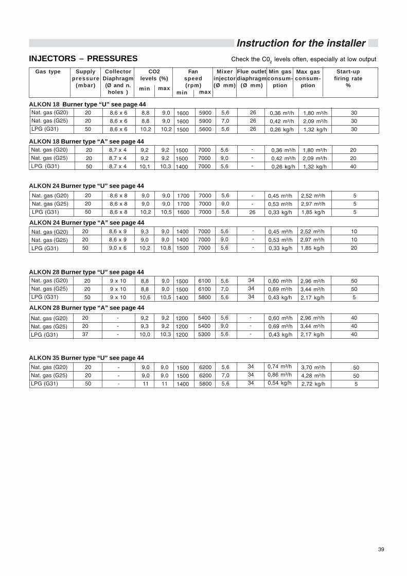
39
Instruction for the installerCheck the C02 levels often, especially at low outputINJECTORS – PRESSURES
Fanspeed(rpm)
Gas type Supplypressure
(mbar)
Min gasconsum-
ption
CollectorDiaphragm(Ø and n.holes )
Mixerinjector(Ø mm)
Flue outletdiaphragm
(Ø mm)
CO2levels (%)
min maxmin max
Start-upfiring rate
%
Max gasconsum-
ption
8,8
8,8
10,6
6100
6100
5800
20
20
50
0,60 m³/h
0,69 m³/h
0,43 kg/h
2,96 m³/h
3,44 m³/h
2,17 kg/h
1500
1500
1400
9 x 10
9 x 10
9 x 10
9,0
9,0
10,5
5,6
7,0
5,6
34
34
34
9,0
9,0
11
6200
6200
5800
20
20
50
0,74 m³/h
0,86 m³/h
0,54 kg/h
3,70 m³/h
4,28 m³/h
2,72 kg/h
1500
1500
1400
-
-
-
9,0
9,0
11
5,6
7,0
5,6
34
34
34
50
50
5
50
50
5
9,0
9,0
10,2
7000
7000
7000
20
20
50
0,45 m³/h
0,53 m³/h
0,33 kg/h
2,52 m³/h
2,97 m³/h
1,85 kg/h
1700
1700
1600
8,6 x 8
8,6 x 8
8,6 x 8
9,0
9,0
10,5
5,6
9,0
5,6
-
-
26
5
5
5
8,8
8,8
10,2
5900
5900
5600
20
20
50
0,36 m³/h
0,42 m³/h
0,26 kg/h
1,80 m³/h
2,09 m³/h
1,32 kg/h
1600
1600
1500
8,6 x 6
8,6 x 6
8,6 x 6
9,0
9,0
10,2
5,6
7,0
5,6
26
26
26
30
30
30
ALKON 28 Burner type “U” see page 44
ALKON 35 Burner type “U” see page 44
ALKON 24 Burner type “U” see page 44
ALKON 18 Burner type “U” see page 44
ALKON 28 Burner type “A” see page 449,2
9,3
10,0
5400
5400
5300
20
20
37
0,60 m³/h
0,69 m³/h
0,43 kg/h
2,96 m³/h
3,44 m³/h
2,17 kg/h
1200
1200
1200
-
-
-
9,2
9,2
10,3
5,6
9,0
5,6
-
-
-
40
40
40
ALKON 24 Burner type “A” see page 44
ALKON 18 Burner type “A” see page 449,2
9,2
10,1
7000
7000
7000
20
20
50
0,36 m³/h
0,42 m³/h
0,26 kg/h
1,80 m³/h
2,09 m³/h
1,32 kg/h
1500
1500
1400
8,7 x 4
8,7 x 4
8,7 x 4
9,2
9,2
10,3
5,6
9,0
5,6
-
-
-
20
20
40
9,3
9,0
10,2
7000
7000
7000
20
20
50
0,45 m³/h
0,53 m³/h
0,33 kg/h
2,52 m³/h
2,97 m³/h
1,85 kg/h
1400
1400
1500
8,6 x 9
8,6 x 9
9,0 x 6
9,0
9,0
10,8
5,6
9,0
5,6
-
-
-
10
10
20
Nat. gas (G20)
Nat. gas (G25)
LPG (G31)
Nat. gas (G20)
Nat. gas (G25)
LPG (G31)
Nat. gas (G20)
Nat. gas (G25)
LPG (G31)
Nat. gas (G20)
Nat. gas (G25)
LPG (G31)
Nat. gas (G20)
Nat. gas (G25)
LPG (G31)
Nat. gas (G20)
Nat. gas (G25)
LPG (G31)
Nat. gas (G20)
Nat. gas (G25)
LPG (G31)
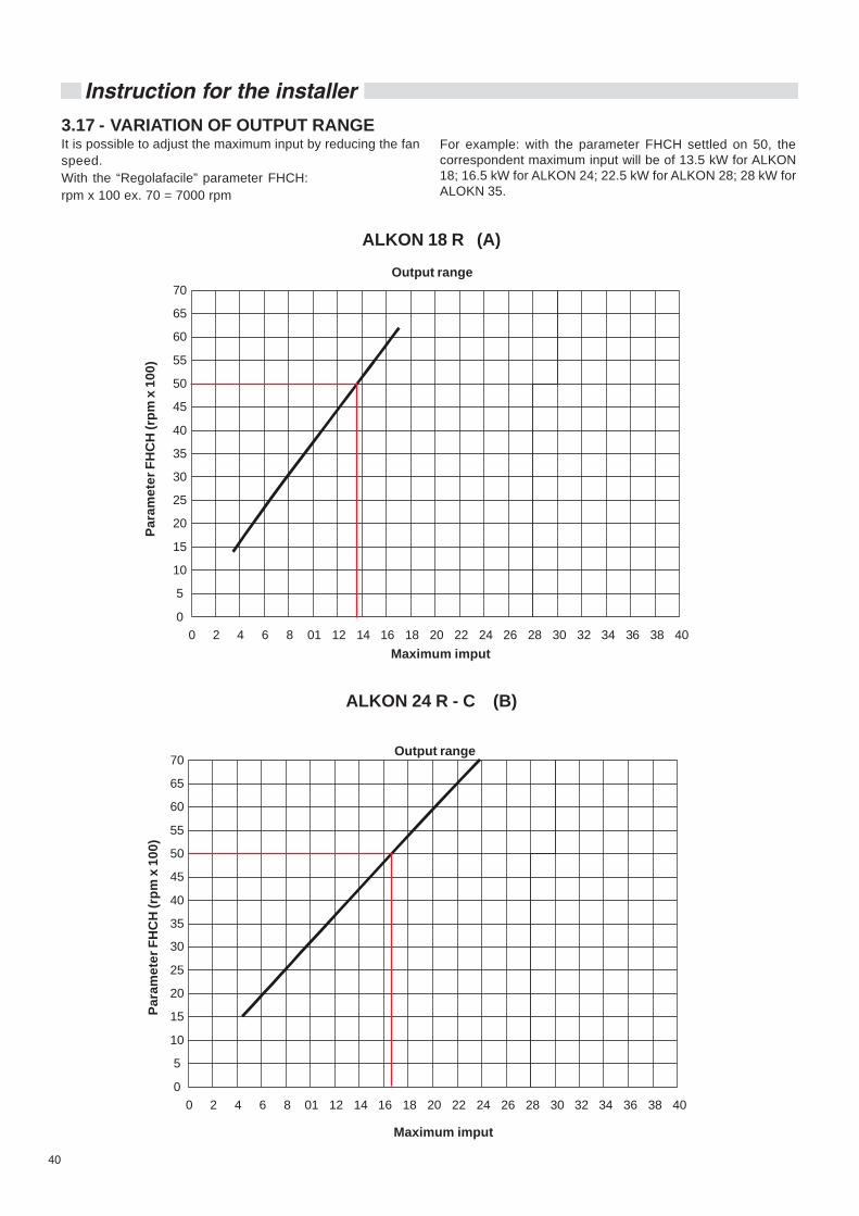
40
Instruction for the installer
ALKON 18 R (A)
ALKON 24 R - C (B)
3.17 - VARIATION OF OUTPUT RANGEIt is possible to adjust the maximum input by reducing the fanspeed.With the “Regolafacile” parameter FHCH:rpm x 100 ex. 70 = 7000 rpm
For example: with the parameter FHCH settled on 50, thecorrespondent maximum input will be of 13.5 kW for ALKON18; 16.5 kW for ALKON 24; 22.5 kW for ALKON 28; 28 kW forALOKN 35.
0 2 4 6 8 01 12 14 16 18 20 22 24 26 28 30 32 34 36 38 400
5
10
15
20
25
30
35
40
45
50
55
60
65
70
0 2 4 6 8 01 12 14 16 18 20 22 24 26 28 30 32 34 36 38 400
5
10
15
20
25
30
35
40
45
50
55
60
65
70
Output range
Maximum imput
Para
met
er F
HC
H (r
pm x
100
)
Output range
Maximum imput
Para
met
er F
HC
H (r
pm x
100
)
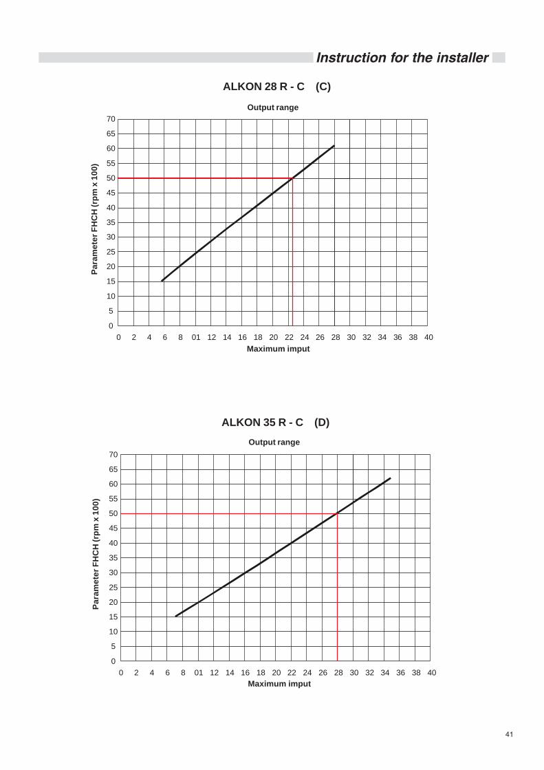
41
Instruction for the installer
ALKON 28 R - C (C)
ALKON 35 R - C (D)
0 2 4 6 8 01 12 14 16 18 20 22 24 26 28 30 32 34 36 38 400
5
10
15
20
25
30
35
40
45
50
55
60
65
70
0 2 4 6 8 01 12 14 16 18 20 22 24 26 28 30 32 34 36 38 400
5
10
15
20
25
30
35
40
45
50
55
60
65
70
Output range
Maximum imput
Para
met
er F
HC
H (r
pm x
100
)
Output range
Maximum imput
Para
met
er F
HC
H (r
pm x
100
)

42
Inspections and servicing schedule
Relationship between the temperature (°C) and the nominalresistance (Ohm) of the CH sensor and the DHW sensors.
T°C 0 1 2 3 4 5 6 7 8 90 32755 31137 29607 28161 26795 25502 24278 23121 22025 2098710 20003 19072 18189 17351 16557 15803 15088 14410 13765 1315320 12571 12019 11493 10994 10519 10067 9636 9227 8837 846630 8112 7775 7454 7147 6855 6577 6311 6057 5815 558440 5363 5152 4951 4758 4574 4398 4230 4069 3915 376850 3627 3491 3362 3238 3119 3006 2897 2792 2692 259660 2504 2415 2330 2249 2171 2096 2023 1954 1888 182470 1762 1703 1646 1592 1539 1488 1440 1393 1348 130480 1263 1222 1183 1146 1110 1075 1042 1010 979 94990 920 892 865 839 814 790 766 744 722 701
TABLE OF RESISTANCE VALUES AS A FUNCTION OF THE HEATING SENSOR (SR) AND DHW (SS) TEMPERATURESENSORS
Example: At 25°C, the nominal resistance is 10067 OhmAt 90°C, the nominal resistance is 920 Ohm
To ensure the continued safe and efficientoperation of the boiler it is highlyrecommended that it is checked at regularintervals and serviced when necessary, andthat only original spare parts are used.Regular attention will prolong the life of theboiler.
If the boiler is not checked and servicedregularly it could cause material andpersonal damages.
For this reason UNICAL recommends that a servicing contractshould be made with our authorized After Sales ServiceAssistance Centre.
The boiler must have regular maintenance and cleaning in orderto ensure reliable and efficient operation. Regular attentionwill prolong the life of the boiler.
The frequency of servicing will be determined by the serviceengineer and will depend on the appliance’s state of condition.
4 INSPECTION AND SERVICING SCHEDULE
INSTRUCTIONS FOR INSPECTION ANDSERVICING
To ensure a long life to all your boilercomponents and in order not to alter theconditions of the approved product, onlyoriginal UNICAL spare parts must be used.
Before servicing always carry out the following steps:- Disconnect the mains electricity supply.- Separate the appliance from the electrical supply by me-
ans of a separating device with an opening contact of atleast 3 mm (for example safety devices or power switches)and ensure yourself that it cannot be accidentally reinser-ted.
- Close the on-off valve fitted upstream of the boiler.- If necessary, and in function of the type of work to be car-
ried out, close any on-off valves fitted on the CH flow andreturn pipes, as well as the cold water inlet valve.
- Remove the appliance’s front panel.
After having carried out all the necessary maintenance workalways follow these steps:- Open the CH flow and return valves as well as the cold inlet
valve (if previously closed),- Purge and, if necessary, proceed with restoring the hea-
ting system’s pressure until a pressure of 0,8/1 bar is rea-ched.
- Open the on-off gas cock.- Reconnect the appliance to the electrical supply and switch
on the mains electrical supply.- Test for gas soundness, on the gas side and on the water
side.- Replace the appliance’s front panel.
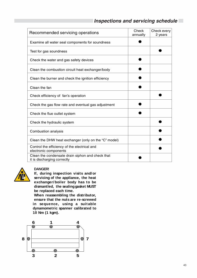
43
Inspections and servicing schedule
Recommended servicing operations
Examine all water seal components for soundness
Clean the combustion circuit heat exchanger/body
Clean the fan
Check the gas flow rate and eventual gas adjustment
Check the flue outlet system
Check the hydraulic system
Combustion analysis
Clean the DHW heat exchanger (only on the “C” model)
Control the efficiency of the electrical and electronic components
Check annually
Check every 2 years
Check efficiency of fan’s operation
Test for gas soundness
Clean the burner and check the ignition efficiency
Clean the condensate drain siphon and check that it is discharging correctly
Check the water and gas safety devices
16
8
3 2
4
5
7
DANGER!If, during inspection visits and/orservicing of the appliance, the heatexchanger/boiler body has to bedismantled, the sealing gasket MUSTbe replaced each time.When reassembling the distributor,ensure that the nuts are re-screwed
in sequence, using a suitabledynamometric spanner calibrated to10 Nm (1 kgm).
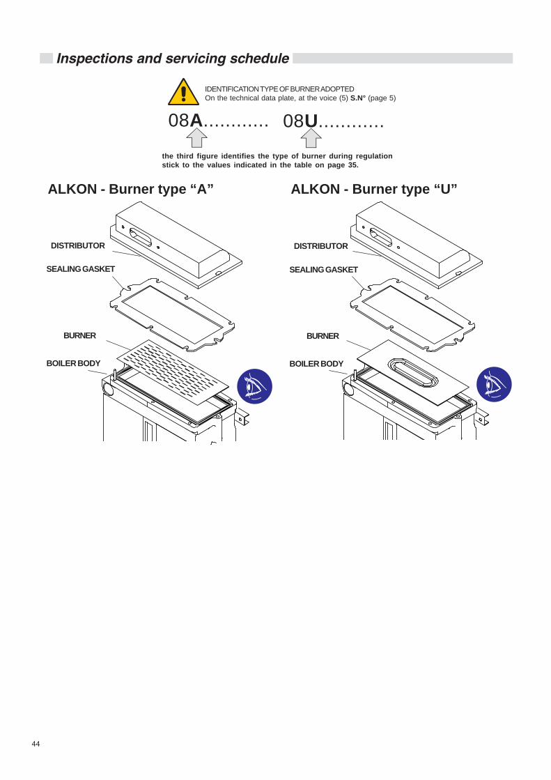
44
Inspections and servicing schedule
IDENTIFICATION TYPE OF BURNER ADOPTEDOn the technical data plate, at the voice (5) S.N° (page 5)
the third figure identifies the type of burner during regulationstick to the values indicated in the table on page 35.
08A............ 08U............
ALKON - Burner type “U”ALKON - Burner type “A”
DISTRIBUTOR
SEALING GASKET
BURNER
BOILER BODY
DISTRIBUTOR
SEALING GASKET
BURNER
BOILER BODY

45
Codes fault
CODE DISPLAYED ONTHE DIGITAL ROOM
CONTROLLER
00000
The boiler is fitted with an integrated diagnostic readout which,in case of malfunction, consents the immediate individuationof the type of fault, thanks to the combination of several LEDs(flashing/on/off) on the control panel display.Below are listed the types of recognized fault codes.
CODE DISPLAYED ONTHE DIGITAL ROOM
CONTROLLER
1111166666
Return temperature sensorDescription:Interruption or short circuit of the return sensor.
CODE DISPLAYED ONTHE DIGITAL ROOM
CONTROLLER
0303030303
Service parametersDescription:Alteration of the service parameters caused by electromagneticdisturbances.
CODE DISPLAYED ONTHE DIGITAL ROOM
CONTROLLER
2121212121
Insufficient water circulationDescription:It is detected when the temperature difference between theflow temperature sensor and the return temperature sensor is> 35°C.It is annulled when the temperature difference is < 25°C.
CODE DISPLAYED ONTHE DIGITAL ROOM
CONTROLLER
0404040404
Fan speed adjustment errorDescription:The fan does not reach the requested speed.
CODE DISPLAYED ONTHE DIGITAL ROOM
CONTROLLER
0606060606
Overheat heat exchangerDescription:It is activated when the flow temperature detected by the sensorin the DHW mode is > 89°C (>92°C in CH mode).The code is annulled when the temperature detected by thesensor in DHW mode is <75°C (<80°C in CH mode).
These codes are divided into the following 3 groups:1st group: they are signalled but boiler operation is normal.2nd group: the burner is automatically switched off.3rd group: the burner is automatically switched off. To reset
the boiler it is necessary to disconnect the boilerfrom the mains supply.
1° GROUP
2° GROUP
Led On and flashing Led On and constantly illuminated Led Off
5 FAULT CODES
No flame detectionDescription:No flame detection during ignition phase: faulty ionisationelectrode.Refire the boiler by pressing the reset button.

46
Codes fault
CODE DISPLAYED ONTHE DIGITAL ROOM
CONTROLLER
0909090909
FrostDescription:The heat exchanger is frozen. If the heating sensor detects atemperature below 2°C burner ignition remains blocked untilthe sensor detects a temperature above 5°C.
CODE DISPLAYED ONTHE DIGITAL ROOM
CONTROLLER
1111100000
High Limit thermostatDescription:A temperature of >100 is detected at the heatexchanger.The boiler can refired by pressing the reset key (if thelimit thermostat is closed)
CODE DISPLAYED ONTHE DIGITAL ROOM
CONTROLLER
1111133333
CH temperature sensorDescription:Interruption or short circuit of the CH sensor.
CODE DISPLAYED ONTHE DIGITAL ROOM
CONTROLLER
1111144444
DHW temperature sensorDescription:Interruption or short circuit of the DHW sensor.
CODE DISPLAYED ONTHE DIGITAL ROOM
CONTROLLER
1111111111
Factory parametersDescription:Alteration of the factory parameters caused by electromagneticdisturbances.Restore the parameters via the remote control.
CODE DISPLAYED ONTHE DIGITAL ROOM
CONTROLLER
1111199999
Incorrect flame detectionDescription:Flame detection with burner Off.
CODE DISPLAYED ONTHE DIGITAL ROOM
CONTROLLER
1111122222
Internal faultDescription:Internal fault within the modulation board.
3° GRUPPO
CODE DISPLAYED ONTHE DIGITAL ROOM
CONTROLLER
0808080808
Lack of waterDescription:Insufficient water pressure and subsequent intervention of theminimum water pressure switch.
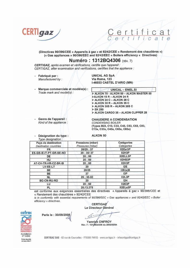

AG S.P.A.46033 casteldario - mantova - italia - tel. 0376/57001 (r.a.) - fax 0376/660556
www.unical.ag - [email protected] Unical decl ines every responsibi l i ty for the possible inaccuracies i f owed to errors of transcript or press. Alsoreserves the right to bring those changes that it will hold necessary to it own products or profits, without jeopardizing itsessent ial character ist ics.