LI-3000A Portable Area Meter LI-3050A Belt...
64
LI-3050A Belt Conveyer LI-3000A Portable Area Meter Instruction Manual ®
Transcript of LI-3000A Portable Area Meter LI-3050A Belt...

LI-3050A Belt Conveyer
LI-3000A Portable Area Meter
InstructionManual
®

LI-3000A Portable Area Meter
LI-3050A Transparent BeltConveyer
Instruction Manual
Publication No. 8805-0055 June, 1988
LI-COR, inc.4421 Superior Street
P.O. Box 4425Lincoln, Nebraska 68504-0425 USA
Telephone: (402) 467-3576FAX: 402-467-2819
Toll-free 1-800-447-3576 (U.S. & Canada)
i
IBM is a registered trademark of International Business Machines Corp.PC-Talk is a trademark of Freeware.ProComm is a trademark of Datastorm Technologies Inc.Apple®, is a registered trademark and Macintosh* is a trademark licensed to AppleComputer Inc.
NOTICE
The information contained in this document is subject to change without notice.
LI-COR MAKES NO WARRANTY OF ANY KIND WITH REGARD TO THISMATERIAL, INCLUDING, BUT NOT LIMITED TO THE IMPLIEDWARRANTIES OF MERCHANTABILITY AND FITNESS FOR APARTICULAR PURPOSE. LI-COR shall not be liable for errors contained hereinor for incidental or consequential damages in connection with the furnishing,performance, or use of this material.
This document contains proprietary information which is protected by copyright.All rights are reserved. No part of this document may be photocopied, reproduced,or translated to another language without prior written consent of LI-COR, Inc.
© Copyright 1988, LI-COR, Inc.

ii
How to Use This ManualThis manual contains the operation instructions for both the LI-3000APortable Area Meter and the LI-3050A Transparent Belt ConveyerAccessory. If you purchased an LI-3000A but not an LI-3050A, you maywish to skip Section VI which contains information on the LI-3050A.
If you already own an LI-3000A and have purchased only an LI-3050A, youwill want to skip directly to Section VI which has the LI-3050A operationinstructions.
If you want to operate the LI-3000A console with an LI-3100 Area Meteryou will want to read Section IV to learn how to connect the LI-3000A tothe LI-3100 and then read Section III for instrument operation instructions.
If you have purchased the 3000A-01 Readout Console to upgrade an olderLI-3000A Portable Area Meter, you will want to read Sections II and III. Ifyour sensor head has not been calibrated to your console you should alsoread the sensor head calibration information in Section V.
Printing History
New editions of this manuals will incorporate all material since the previous edition.The manual printing date indicates its current edition. The printing date changeswhen a new edition is printed. (Minor corrections and updates which areincorporated at reprint do not cause the date to change.)
Edition 1 - June 1988

iii
Table of Contents
SECTION I. General Information
System Description ............................................................................... 1-1Theory of Operation .............................................................................. 1-2Instrument Calibration .......................................................................... 1-3
SECTION II. Preoperation Procedures
Operational Check................................................................................. 2-1Recharging the Battery .......................................................................... 2-2Using the Waist Strap............................................................................ 2-3
SECTION III. Instrument Operation
Power On............................................................................................... 3-1Basic Operation ..................................................................................... 3-1Making Measurements .......................................................................... 3-5Storing Data In Memory ....................................................................... 3-10Menu Key Routines .............................................................................. 3-16Data Communications ........................................................................... 3-21
SECTION IV. Operation with the LI-3100 Area Meter
Operation with the LI-3100 Area Meter ............................................... 4-1

iv
SECTION V. Maintenance
Cleaning the LED and Photodiode Windows ....................................... 5-1Cleaning the Length Encoding Cord Guide .......................................... 5-1Length Encoding Cord .......................................................................... 5-1Knob Separation from the Length Encoding Cord................................ 5-2Battery Replacement ............................................................................. 5-2Internal Fuse .......................................................................................... 5-3Instrument Storage ................................................................................ 5-4Test Menu.............................................................................................. 5-4
SECTION VI. LI-3050A Transparent Belt Conveyer
Setup and Adjustment ........................................................................... 6-1Storage and Maintenance ...................................................................... 6-3
APPENDIX
APPENDIX A. LI-3000A Specifications ............................................ A-1APPENDIX B. LI-3050A Specifications............................................. A-2
WARRANTYOBTAINING SERVICE FOR YOUR INSTRUMENT

1-1
Section IGeneral Information
System DescriptionThe LI-COR Model LI-3000A Portable Area Meter utilizes an electronicmethod of rectangular approximation to measure leaf area on intact plants ofmany species. The LI-3000A has two components, the Scanning Head andthe Readout Console. Area data is logged by the Readout Console as theScanning Head is passed over the leaf.
The LI-3000A console replaces the LI-3000 Portable Area Meter readoutconsole. The scanning heads on both instruments are the same. TheLI-3000A has the following features:
• Displays leaf length, average width, and maximum width in addition toarea and accumulated area.
• Readings can be summed in a secondary summing register at the user'scommand. The previous reading added to the register can be subtractedfrom it.
• Readings can be stored in the console, and later output to a computer orprinter (RS-232C interface).
• The console can be connected to any LI-3000 Portable Area Meterscanning head. The console will self-calibrate heads with serialnumbers 197 and above. Heads with serial numbers PAM196 andbelow require a specially configured console which does notself-calibrate.
• The console can be used with either the LI-3050A Transparent BeltConveyer Accessory, or the LI-3100 Area Meter (requires a minormodification of LI-3100's with serial numbers LAM652 and below).
• A rechargeable sealed lead acid battery provides power for portableoperation. The battery life is approximately 15 hours.
The LI-3000A has been designed for field use. Operate and store it withcare similar to that required for a camera. The 3000A-02 Carrying Case isrecommended.
The optional accessories for the LI-3000A include the 3000A-02 CarryingCase, the LI-3050A Transparent Belt Conveyer Accessory, the 3000A-03Interface Cable (for LI-3100 to LI-3000A), the 6000-03B RS-232C printer,

General Information
1-2
and the 3000A/SM Service Manual. Replacement and service items arelisted in Section V.
Theory of OperationThe method by which the LI-3000A measures area is best understood byexamining the technique for manual area measurement. Manual areameasurement requires tracing the outline of the sample on graph paper andmethodically counting the squares where the sample covers fifty percent ormore of the area of an individual grid cell.
The 50% criterion for the acceptance or rejection of grid cells is necessaryto maintain linearity in the measured area. In other words, if the grid cellswith fifty percent or more area covered were not counted, the result wouldbe inconsistent data on repeated measurements. Similarly, if a sample werecut into pieces and the individual pieces summed, the results would likelynot equal the measurement of the whole sample (unless the 50% criterionwas used).
The width of the sample at a given point is determined by the number ofgrid cells covered across a row. The number of grid cells covered in acolumn determines the length. The resolution of this measurementtechnique is a function of the area represented by each grid cell.
The function of the LI-3000A Portable Area Meter is to use electronicmethods to simulate a grid pattern on the leaf. The scanning head uses arow of 128 narrow band, red, light-emitting diodes (LEDs), spaced on 1 mmcenters, to examine 128 grid cells across the width of the leaf. The LEDs aresequentially pulsed (only one LED is lit at a time) to examine a particulargrid cell in the row. The LEDs are located along a line 0.62 cm (0.25 in.)from the edge of the upper section of the scanning head.
The base of the scanning head contains a lens-photodiode system whichresponds only to the collimated, pulsed LED light. This design makes themeasurements insensitive to other light sources. These narrow-band redLEDs and associated digital circuitry provide measurements which areunaffected by leaf transmission properties.
After each grid cell in the row is scanned, it is necessary to advance to thenext row. Electronically, this is accomplished by pulling the lengthencoding cord. After each 1 mm of cord travel, a new scan is initiated inwhich each of the 128 LEDs are sequentially pulsed. The scanning processbegins only when the length encoding cord is pulled.

General Information
1-3
Since 1 mm of cord travel is equivalent to the side of a grid cell, it isapparent that the length encoding cord must be pulled perpendicular to therow of 128 LEDs.
When the LED light is blocked by a sample, the unit area (1 mm2 ) isaccumulated on the display. For example, if a 20 × 100 mm sample is beingmeasured, 20 LEDs will be masked for 100 scans resulting in a display of20.00 cm2 .
LEDs which are only partially blocked are also accounted for. Thecalibration adjustment potentiometer (CAL ADJ) on the side of the consoleis adjusted at the factory so that 1 mm2 of area is accumulated on thedisplay when the LED light is diminished by 50% or more.
The scanning head accurately measures irregularly shaped leaves or leaveswith holes from insect damage. As a hole in the leaf passes through thescanning head, the photodiodes sense LED light, and that LED locationdoes not contribute to the area accumulating on the display until the LEDsare once again masked when the hole has passed.
The important aspect of this electronic measurement technique is that itrequires that the light emitted from each of the 128 LEDs be uniform inintensity so that the 50% acceptance/rejection threshold is consistent foreach grid cell. This is accomplished by the autocalibration software duringthe calibration process.
Instrument CalibrationThe scanning head is calibrated to the readout console at the factory usingthe LI-3000A's built-in autocalibration routine (Section V). If a differentscanning head is to be used, the autocalibration routine must be performedto calibrate the head to the console. The autocalibration routine computeshow much current each of the 128 LEDs requires in order to achieve aconstant brightness. These calibration values are retained as a table in thememory of the console.
General Information
1-4
IMPORTANT: Scanning heads with serial numbers PAM196 and below require aspecially configured LI-3000A. Consoles so configured should NEVER be used with headshaving serial numbers PAM197 and above. Damage to these heads could result. Similarly,standard consoles should NEVER be used on heads with serial numbers PAM196 and below.The only exception to this is if the area meter head with serial number PAM196 or below hasbeen updated by LI-COR. It would then be treated as having a serial number greater thanPAM196 and could then be used on a standard console.
THE CAL ADJUST POTENTIOMETER
The calibration accuracy is effected by the "CAL ADJ" potentiometer asdescribed in the theory section. This potentiometer is adjusted at the factoryto provide ± 2% accuracy for measurements with the scanning head, or thescanning head with a transparent sheath. The "CAL ADJ" potentiometeris adjusted by the user only when the LI-3000A is used with theLI-3050A Transparent Belt Conveyer Accessory. This adjustment isdiscussed in Section VI.
If the "CAL ADJ" potentiometer has been adjusted for use with theLI-3050A, and it is also desired to use the LI-3000A in a portable mode(without the LI-3050A), it is not necessary to adjust the CAL ADJpotentiometer. For a typical scanning head, the accuracy differencebetween the factory setting of the CAL ADJ potentiometer and the adjustedsetting used for the LI-3050A will introduce an error of 0.4 to 0.6%. Themeasurement errors ( ± 2% accuracy) in portable mode are much moresignificant. (Measurement errors in portable mode include not pulling thelength encoding cord perpendicular to the line of LEDs, and the errorintroduced by not measuring the portion of the leaf that is between the edgeof the scanning head and the row of LEDs.)

2-1
Section IIPreoperation Procedures
Operational CheckThe following procedure can be used to connect the scanning head to thereadout console and verify that the LI-3000A is working properly.
1) Connect the scanning head to the readout console while the ON/OFFswitch is OFF, and then switch the ON/OFF switch to ON.
A start-up message (Section III) indicates which scanning head iscalibrated to the console. If the scanning head serial number does notmatch the serial number given in the start-up message you will need tocalibrate that head to the readout console using the built-inautocalibration routine (Section VI).
If the symbol "Lo" appears on the display (see Recharging the Battery)when the readout console is turned on, the internal battery needscharging. The low battery message is displayed when 1 hour ofoperational capacity remains in the battery. If your battery is low, skipdown to the information on recharging the battery found later in thissection.
If the message "CALIBRATION LOST PRESS ANY KEY" is displayedwhen the instrument is turned on, the calibration table has been deletedbecause of a power interruption to the memory (RAM). The scanninghead can be calibrated to the console as described in Section V.
2) Open the scanning head by pressing on the thumb lever which is part ofthe upper section (Figure 2, Section III). Hold the scanning headinverted and look into the long narrow window near the edge of thehead. Pull the length encoding cord out and retract it. You should beable to see the LEDs as they rapidly pulse.
IMPORTANT: Retract the cord by holding the knob and allowing thecord to draw into the head by its own force. The cord should not beallowed to snap back into the head. Also, do not push the cord andcause slack; internal backlash may result.

Preoperation Procedures
2-2
If you have been holding the head open while pulling the encoding cord,you will notice that numbers are being accumulated on the display. Thisis because the photodiodes will only accept the collimated light from theLEDs when the components are positioned properly. This characteristicwas designed into the instrument to prevent stray light from affectingnormal data collection. With the scanning head open, the LEDs and thephotodiodes are out of alignment so area is recorded as the lengthencoding cord is moved. If the cord is drawn or retracted at a rategreater than 1 m/second, an error message is displayed as described inSection III. (The error message can be cleared by pressing the CLEARX key.)
3) Clear any logged area data by pressing the white reset switch located onthe scanning head handle.
Recharging the BatteryThe LI-3000A uses a sealed lead acid battery. This battery is rechargeable,and gives about 15 hours of use. The symbol "Lo" appears on the display(as shown below) when approximately 1 hour of battery life remains.
AREA 0.00 0 Lo 0.00
XY
After automatic shutdown, enough power remains in the battery to maintainthe memory for about 3 months. To prevent memory loss the batteryshould be recharged every 3 months during storage.
To charge the battery, slide the voltage selector on the readout consoleconnector panel to the proper voltage. Connect the power cord to thereadout console and plug the cord into an AC source (115-230 VAC, 50-60Hz).
The battery should normally be charged overnight. An automatic chargingcutoff is provided to prevent overcharging. The instrument may be operatedwhile it is charging; however, the time needed to fully recharge the batterywill be increased.
The LI-3000A's battery will not be harmed by continuous operation withAC power.
There is no internal backup battery, so if the main battery is disconnectedfor more than 20 seconds, all memory in the instrument will be cleared.

Preoperation Procedures
2-3
Using the Waist StrapA waist strap has been provided so that the readout console can be wornaround the waist for portable operation. The waist strap is connected to theconsole using the screws found on the right and left sides of the console.
For maximum comfort, the waist strap should be positioned so that the strapis about the same level as a belt on a pair of pants. In this position theweight of the console will rest on the pelvic bones and not on the "fleshy"part of the back.

3-1
Section IIIInstrument Operation
Power OnBefore turning on the LI-3000A, make the connections to the scanninghead, LI-3050A Transparent Belt Conveyer Accessory, or LI-3100 AreaMeter. At power up, the console will automatically sense whether ascanning head or an LI-3100 is connected.
Basic OperationWHAT THE DISPLAY MEANS
When first turned on, the display of the LI-3000A will be as follows:
LI-3000A 01.00 XY
Briefly displays the software revisionnumber (1.00 in this example).
Calibrated for Head#1611
XY
Briefly displays scanning head serialnumber calibrated to the console.
AREA 0.00 0 0.00
XY
Label = AREA Value = 0.00# Samples = 0 Accumulator = 0.00
The value displayed on the upper line of the display (the X line) can beAREA (cm2 ), LEN (length of sample in cm), AV WD (average width incm), or MX WD (maximum width in cm). The label on the left side of theX line identifies the value on the right side. The value displayed is selectedby pressing the AREA, LEN, AVE WIDTH, or MAX WIDTH keys.

Instrument Operation
3-2
Figure 1. The LI-3000A front panel.
The area is computed as the length multiplied by the average width:
AREA = LEN × AV WD
The X value on the right of the display is the instantaneous value. Thisvalue changes in real time as a sample is measured. The Y value is anaccumulator that you can use if you wish. X values can be added to the Yvalue by pressing ADD. (Pressing the scanning head button twice in rapidsuccession has the same effect as pressing the ADD key.) The SUB keyremoves the last value entered from the Y register (useful if ADD ismistakenly pressed). Note that this "last value" is not necessarily thecurrently displayed X value, and that the last value cannot be removed morethan once.

Instrument Operation
3-3
AN EXAMPLE
1) Put a small piece of paper in the scanning head, pull the string out aseveral centimeters, and let it back. The display will change tosomething like
AREA 158.92 0 0.00
XY
2) Press LEN.
LEN 27.4 0 0.00
XY
Sample length was 27.4 cm.
3) Press AVE WIDTH.
AV WD 5.8 0 0.00
XY
Average sample widthwas 5.8 cm.
4) Press MAX WIDTH.
MX WD 5.8 0 0.00
XY
Maximum sample widthwas 5.8 cm.
5) Press AREA to return to the normal display. Now add the X value tothe Y value by pressing ADD. The display will change to
AREA 0.00 1 158.92
XY
Cleared after ADD.1 value now in the accumulator.

Instrument Operation
3-4
Note that the X value clears after pressing ADD (this feature can bedisabled, and is discussed later), and that the sample counter on the bottomleft increments by one.
6) Pull the string again to measure another sample.
AREA 120.06 1 158.92
XY
The new sample.
7) Add the new X value to the Y value by pressing ADD.
AREA 0.00 2 278.98
XY
2 values in the accumulator.
8) Pull the string again to measure a third value.
AREA 21.46 2 278.98
XY
The third sample.
9) Subtract the last value added to the Y register by pressing SUB.
AREA 21.46 1 158.92
XY
The third sample is still displayed.Note that 120.06 was subtracted.
Since the last value added was 120.06, that was what was removed from theY value. The X value remains unchanged. If you press SUB again, it willhave no effect, since the last entered value has already been removed.

Instrument Operation
3-5
SCANNING HEAD BUTTON
The white button on the LI-3000A scanning head has 2 uses. Pressing oncewill clear the X register (same as pressing CLEAR X ). Pressing thebutton twice in quick succession adds the X value to the Y value, just likepressing ADD.
PULLING THE STRING TOO FAST
If you ever pull the string too fast, the message
PULLING TOO FASTPRESS CLR X
XY
will be displayed. When CLEAR X is pressed, the X value will be cleared,and normal operation will resume. Maximum string speed is about 1 meterper second.
Making MeasurementsWhen using the scanning head on attached leaves, observe the following 2important principals:
• Pull the length encoding cord at the same rate the sample is beingpulled through the scanning head. This is accomplished by holdingthe length encoding knob against a stationary object (stem, etc.) asthe scanning head is drawn over the sample.
• Pull the length encoding cord straight out from (perpendicular to)the front plane of the scanning head (an angle of 11.5 degrees willcause a 2% error).
AREA MEASUREMENT OF ATTACHED LEAVES
1) Move the ON-OFF switch to ON.2) Open the scanning head and position it over a leaf. The leaf does not
have to be detached from the plant to be measured.
Instrument Operation
3-6
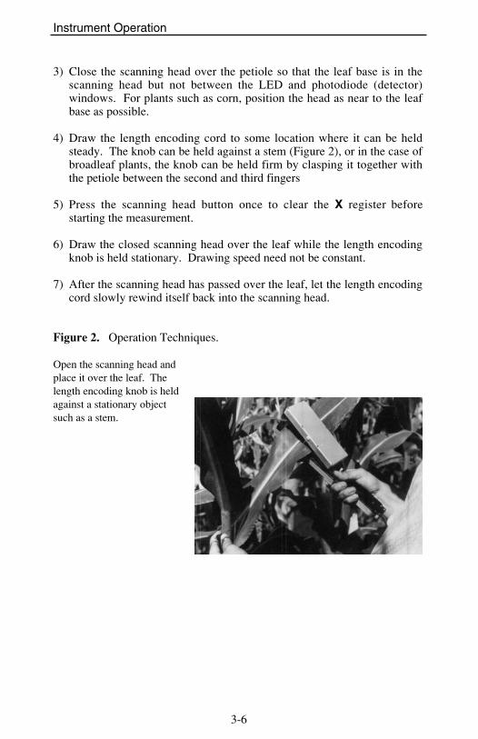
3) Close the scanning head over the petiole so that the leaf base is in thescanning head but not between the LED and photodiode (detector)windows. For plants such as corn, position the head as near to the leafbase as possible.
4) Draw the length encoding cord to some location where it can be heldsteady. The knob can be held against a stem (Figure 2), or in the case ofbroadleaf plants, the knob can be held firm by clasping it together withthe petiole between the second and third fingers
5) Press the scanning head button once to clear the X register beforestarting the measurement.
6) Draw the closed scanning head over the leaf while the length encodingknob is held stationary. Drawing speed need not be constant.
7) After the scanning head has passed over the leaf, let the length encodingcord slowly rewind itself back into the scanning head.
Figure 2. Operation Techniques.
Open the scanning head andplace it over the leaf. Thelength encoding knob is heldagainst a stationary objectsuch as a stem.

Instrument Operation
3-7
Close the scanning head atthe leaf base. Reset the instru-ment by pressing the scanninghead button once.
Draw the closed scanning headover the leaf apex to passthrough completely. Drawingspeed need not be constant.
Figure 3. Soybean Measurement.

Instrument Operation
3-8
USING A TRANSPARENT SHEATH
A transparent sheath (user supplied) can be used to measure detached leavesand other objects that require sample support (Figure 4). In order to gainproficiency using a transparent sheath, measure several objects of knownarea, such as graph paper cutouts.
If detached leaves are to be measured with a sheath, make the measurementsas soon as possible after harvesting with the samples kept moist to preventshrinkage or curling of the leaf margins.
Measurements with a transparent sheath can be accomplished using thefollowing steps:
1) Make sure the sheath is clean and then measure the empty sheath to becertain that know spurious area is measured.
2) Place an object in the sheath about 6 cm from one end.
3) Open the scanning head and place the sheath in the head with about 4 cmprotruding from the left edge and allow the head to close.
Figure 4. Use of the Transparent Sheath

Instrument Operation
3-9
4) Grasp the length encoding knob with your left-hand thumb andforefinger and hold it stationary against the sheath (Figure 4).
5) Press the scanning head button once to clear the X value on the display.Draw the sheath through the scanning head, simultaneously drawing outthe length encoding cord.
HINTS FOR VARIOUS LEAF TYPES
Many types of leaves cannot be measured without additional support toguide them through the scanning head. Techniques for several leaf typesare discussed below.
• Compound leaves can be measured by either scanning each leaflet, aswith the soybean trifoliate in Figure 3, or by enclosing the entire intactleaf in a transparent sheath.
• Tender leaves such as those developed under low light conditionssometimes will not easily slide through the scanning head and mayactually tear because of adherence to the instrument surfaces. In this casea transparent sheath can be placed over the leaf for support andprotection.
• Insect damaged leaves which have protruding fragments or naturallydissected leaves having fine lobes usually require support by a transparentsheath.
• Small leaves such as those of alfalfa and small grasses can be removedfrom the plants and placed in a transparent sheath.
• Elongated, narrow leaves (grasses, etc.) are most accurately measured ifthey are passed through the scanning head at an angle to the line of LEDs(instead of perpendicular).
In many cases the LI-3050A/4 Transparent Belt Conveyer Accessory(Figure 5) will be the method of choice for measuring small objects anddetached leaves. The combination of the LI-3050A/4 and LI-3000Aprovides greater accuracy ( ± 1%) than the LI-3000A alone ( ± 2%).

Instrument Operation
3-10
Storing Data In MemoryReadings can be stored in memory for later viewing or RS-232C output.
Stored readings can be any combination of the X register and theaccumulated readings in the Y register. When data is stored, itautomatically includes area, length, average width, and maximum width.
Stored data is in a file system. A file can be as large or as small as you wish.A file must be opened before any data is stored. Closing the file precludesadding any more data to that file. Associated with each file is some headerinformation: a number (assigned by the system), a label (entered by theuser), and the time and date the file was opened (as kept by the system).
When output, a file might look like this:
FILE: 1REM:PLOT106 MAY 1990 14:22:30ENTRY COUNT AREA LENGTH AV WIDTH MX WIDTH1 0 42.37 13.10 3.23 5.122 5 344.20 120.00 2.87 3.103 2 84.48 26.80 3.15 6.02
FILE: A sequential number assigned by the system that you use toreference the file.
REM: A remark entered by the user when the file is first opened.ENTRY: Sequential numbers identifying records in the file.COUNT: The number of samples represented in the record. When X
values are stored, the count is always 0. Y values will always be aninteger greater than 0. The count represents the number of X values thatwere added together before the accumulated Y value was stored in thefile.
For accumulated values, the AREA value is the total leaf area of allsamples, LENGTH is the total leaf length, AV WIDTH is the average widthof all samples, and MX WIDTH is the maximum width of all samples.
The following sequence of events could have occurred to make the abovefile. It would be a good example to duplicate using your own console, aswell.

Instrument Operation
3-11
1) Press FILE to open a file. The display will show
FILE 1 OPENED XY
Briefly displayed...
ENTER REMARK:__
XY
2) The remark "PLOT1" is entered by pressing this sequence of keys:
P ↑ L ↑ O T ↑ SPACE 1 ENTER
To type the alpha characters in the lower left corners of the keys, just pressthe desired key. To type the alpha characters in the upper left corners, press↑ first, then the key. Typing mistakes can be corrected using the back arrowkey (←).
3) Now the display will show
AREA * 0.00 0 0.00
XY
The * indicates that a file is open.
4) Measure a sample ....
AREA * 42.37 0 0.00
XY
... and store it by pressing STORE X. The display will briefly show
FILE 1ENTRY 1_
XY
followed by
Instrument Operation
3-12
AREA * 0.00 0 0.00
XY
Note the X value clears after pressingSTORE X.
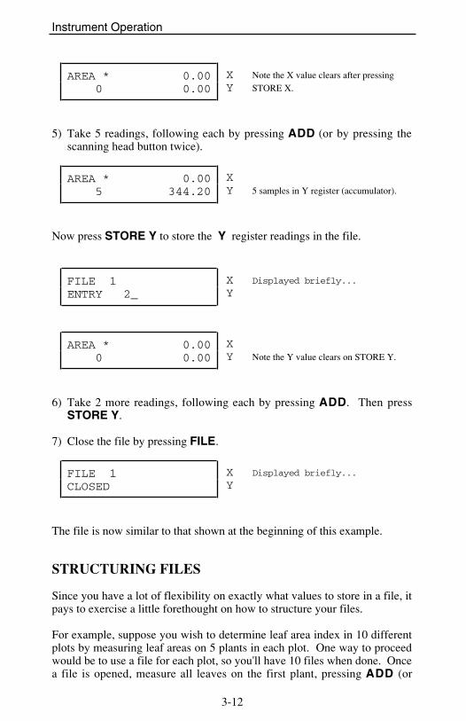
5) Take 5 readings, following each by pressing ADD (or by pressing thescanning head button twice).
AREA * 0.00 5 344.20
XY 5 samples in Y register (accumulator).
Now press STORE Y to store the Y register readings in the file.
FILE 1ENTRY 2_
XY
Displayed briefly...
AREA * 0.00 0 0.00
XY Note the Y value clears on STORE Y.
6) Take 2 more readings, following each by pressing ADD. Then pressSTORE Y.
7) Close the file by pressing FILE.
FILE 1CLOSED
XY
Displayed briefly...
The file is now similar to that shown at the beginning of this example.
STRUCTURING FILES
Since you have a lot of flexibility on exactly what values to store in a file, itpays to exercise a little forethought on how to structure your files.
For example, suppose you wish to determine leaf area index in 10 differentplots by measuring leaf areas on 5 plants in each plot. One way to proceedwould be to use a file for each plot, so you'll have 10 files when done. Oncea file is opened, measure all leaves on the first plant, pressing ADD (or

Instrument Operation
3-13
press the white button on the scanning head twice) after each leaf. Whendone with the plant, press STORE Y . Repeat for the other 4 plants on theplot. When done with the plot, press FILE to close the file. At that point,you will have 5 entries in the file, each one being the total leaf area of eachof the 5 plants sampled. The COUNT column on each line would tell youhow many leaves per plant were measured.
The file for one plot might look something like this:
FILE: 2REM: TEST PLOT 208 MAY 1988 14:19:30ENTRY COUNT AREA LENGTH AV WIDTH MX WIDTH1 7 246.68 45.10 3.23 5.122 5 125.20 35.60 2.87 3.103 4 84.48 26.80 3.15 6.024 9 344.20 120.00 4.67 6.105 5 140.69 47.32 3.56 5.72
Another approach would be to have one file per plant (giving you 50 fileswhen done). When measuring a plant, press STORE X and ADD aftereach leaf measurement. After the last leaf on the plant is measured, pressSTORE Y to store the accumulated leaf area for that plant and then closethe file. In order to know which plant goes with which plot, use the fileremarks to record that information. The file for one plant might look likethis:
FILE: 3REM: PLOT 2 #509 MAY 1988 14:25:30ENTRY COUNT AREA LENGTH AV WIDTH MX WIDTH1 0 42.37 13.10 3.23 5.122 0 44.20 12.90 2.87 3.103 0 24.48 9.78 3.15 3.674 0 29.50 10.20 2.83 2.985 0 34.86 11.50 2.32 2.766 0 19.33 8.60 2.14 2.567 6 194.74 66.08 2.76 5.12
Still another approach is to use one file for the entire data set. Begin eachplot with a cleared Y and X register, and press ADD after each leaf.When done with a plot, press STORE Y. When done, your file will have

Instrument Operation
3-14
10 entries (one for each plot), and the COUNT for each entry will reflect thetotal number of leaves measured.
Before you decide on how to structure your data files, you may also want toconsider the potential of loosing some of your data. If the console isswitched OFF, or if it automatically shuts itself off due to inactivity, thecurrent X and Y values will be lost. Any data which is stored in a data file(the result of pressing STORE X or STORE Y) is safe, even if the data fileis not closed. The greatest potential for loss occurs when a large number ofmeasurements are added to the accumulator ( Y register) before they arestored in a data file.
The configuration of the LI-3000A can be changed to facilitate rapid datastorage. This is accomplished using the CONFIG REGISTERS routine thatis discussed in the section titled Menu Key Routines.
VIEWING FILES ON THE DISPLAY
The VIEW key allows you to look at the contents of any stored file. Whenthe VIEW key is pressed, you will be prompted for the file number of thefile to be viewed:
VIEW FILENUM:__
XY Enter the file number to be viewed.
If you enter a file number for which there is no file, the display will show
FILE NOT FOUND_ XY
and return to the normal display. Otherwise, you will be shown the headerof the selected file. For a typical file the display would show
FILE 1 ( 3)REM: PLOT 1
XY
File 1 has 3 entries.
Press the ↓ key to see the next part of the file header, which is the date andtime when the file was opened.

Instrument Operation
3-15
06 JUN 198814:22:30
XY
Press the ↓ key again to view the first of the 3 entries.
1/ 3 0AREA 42.37
XY
Entry 1 of 3 has 0 counts (e.g. it wasstored from the X register).
The top line displays the ENTRY number (1), the total entries (3), and theCOUNTS for that entry (0, indicating that it is an X value). The bottomline displays AREA, LEN, AV WD, or MX WD depending upon which hasbeen selected using the AREA , LEN , AVE WIDTH , or MAX WIDTHkeys. Try pressing these keys before proceeding.
Pressing ↓ again will change to the second entry:
2/ 3 5AREA 344.20
XY
Entry 2 of 3 has 5 counts.
VIEW MODE KEY DEFINITIONS
While viewing a file, these keys will do the following things:
↑ and ↓ : Scroll up or down through a file.
VIEW: Will prompt for a new file to view.
DEL: Deletes the file that is currently displayed. When the DEL ispressed, the user is prompted:
DELE 1? N↑,↓, or ENTER
XY
To delete the file press the ↑ key to change the N to a Y, then pressENTER. To continue without deleting the file, just press ENTER.

Instrument Operation
3-16
AREA , LEN , AVE WIDTH , or MAX WIDTH : Selects the datacolumn to be viewed.
All other keys will cause view mode to be exited.
DELETING A RANGE OF FILES
When DEL is pressed from normal operating mode (as opposed to the fileview mode), the user is prompted for a range of files to delete:
DELETE FILESFROM:_
XY
FROM:10THRU:_
XY
If 10 were entered for the startingvalue. Enter the ending value.
Each file in the range that is deleted is shown on the display.
FILE 14DELETED
XY
Counts through a range.Or, resumes area display if not found.
If you wish to get out of the file delete routine, enter 0 (or press ENTERwithout making an entry) for either the FROM or THRU file numbers. (Seealso the discussion below on deleting all files.)
Menu Key RoutinesThe MENU key accesses a list of software routines.
MEMORY AVAILABLE↑,↓, or ENTER
XY

Instrument Operation
3-17
Use the ↑ and ↓ keys to scroll through the list, and press ENTER toperform any one. Press any other key to exit the menu list, and return tonormal operation. The list of routines is:
Memory Available Shows % of memory available for storage.Set I/O Configures the RS-232C port (baud rate, data bits, etc.).Print Files Outputs a user selected range of files to the RS-232C port.Delete All Files Deletes all stored files.Config Registers Can set auto clear on ADD, STORE X, and STORE Y.Set Clock Sets time and date.3100 Resolution Sets high or low resolution if using the LI-3100 Area Meter.
To exit MENU list, press any key except ENTER , ↑ ,or ↓ .
MEMORY AVAILABLE
100% REMAININGPRESS KEY
XY
Displays % of available memory.Press any key to return to help menu.
The actual number of files or area entries that can be stored is highlydependent on how the data is stored as indicated in the table below. Whenthe memory is full the message "NOT ENOUGH MEM" will be displayedwhen you try to store data into a file.
Entries Total #Per File # Files Entries
1 674 6742 526 10523 431 12934 365 14605 316 158010 190 190015 136 204020 105 2100. . .. . .2385 1 2385

Instrument Operation
3-18
SET I/O
The SET I/O routine sequentially prompts for the following list ofparameters:
BAUD = 4800↑,↓, or ENTER
XY
300, 1200, 2400, 4800, or 9600
DATA BITS = 8↑,↓, or ENTER
XY
7 or 8
STOP BITS = 2↑,↓, or ENTER
XY
1 or 2
PARITY = NONE↑,↓, or ENTER
XY
EVEN, ODD, or NONE
DATA BITS = 8↑,↓, or ENTER
XY
7 or 8
CHECK DTR = Y↑,↓, or ENTER
XY
Y or N (Pin 20 high?)
XON/XOFF = N↑,↓, or ENTER
XY
Y or N
CHECK RTS = N↑,↓, or ENTER
XY
Y or N (Pin 4 high?)
CHECK DTR=Y Hardware pacing: DTR line. When set to 'Y' theLI-3000A will send data only when it sees pin 20 (DTR) of the I/O port

Instrument Operation
3-19
high (> 3V). This method of pacing is commonly used in printers (as is thecase with the 6000-03B Printer from LI-COR).
XON/XOFF=N XON/XOFF software handshake. The LI-3000A willtransmit data until an XOFF character (hex 13, ASCII DC3) is received.Data transmission will resume upon receipt of an XON character (hex 11,ASCII DC1). This is a fairly common handshaking protocol.
CHECK RTS=N Hardware handshake. When CHECK RTS is set to "Y",the LI-3000A will only send data when it sees pin 4 (RTS) of the I/O porthigh (> 3V). The 6000-03B Printer does not support this handshakingprotocol (set CHECK RTS to 'N').
More information on transferring data to a computer or printer can be foundin the Data Communications section.
PRINT FILES
This routine prompts the user for a range of files to be transmitted out theRS-232C port. Entering a 0 or just pressing ENTER in response to eitherthe FROM or THRU prompts will abort this routine.
PRINT FILESFROM_
XY
FROM: 10THRU:_
XY
If 10 were entered forthe starting value
DELETE ALL FILES
DELETE FILES = N↑,↓, or ENTER
XY
Pressing ↑ (to change the N to a Y) followed by ENTER will clear all filesfrom memory.

Instrument Operation
3-20
CONFIG REGISTERS
The user can choose whether the X value is automatically cleared when theADD key is pressed (or the white button double pressed), when theSTORE X key is pressed, or whether the Y value is automatically clearedwhen the STORE Y key is pressed.
CLR X ON ADD? Y↑,↓, or ENTER
XY
CLR X ON STORE? Y↑,↓, or ENTER
XY
CLR Y ON STORE? Y↑,↓, or ENTER
XY
These prompts are used to facilitate rapid data collection and storage. Forexample, if you wish to store only accumulated measurements of all leaveson a plant, set "CLR X ON ADD" to Y so that the X value is cleared afterthe area of each leaf is added to the Y value. This eliminates having topress the white scanning head button or the CLEAR X key in-betweeneach leaf measurement.
Now assume that you wish to store the leaf area of each individual leaf andthe total leaf area of the whole plant. Two operations need to occur aftereach leaf is measured; the individual leaf area data should be stored usingthe STORE X key and the individual leaf area data should be added to theY value to collect the whole plant leaf area. To accomplish this, set the"CLR X ON STORE" prompt to No and the "CLR X ON ADD" prompt toYes. This assumes that you will press STORE X before ADD. If youwish to press ADD before STORE X set "CLR X ON ADD" to No and"CLR X ON STORE" to Yes.
Normally it is advantageous to have the "CLR Y ON STORE" prompt set toYes. However, you may find a need to store an accumulated value (such aswhole plant leaf area) and continue to add new measurements afterward.

Instrument Operation
3-21
SET CLOCK
DATE=20 JUN 1988NEW=DD MMM YYYY
XY
TIME=14:32:10NEW=HH:MM:SS
XY
Pressing ENTER without making any entries will leave the data or timeunchanged. To enter a new date or time, type in the appropriate charactersto match the indicated NEW= format.
Valid entries for the months January through December are JAN, FEB,MAR, APR, MAY, JUN, JUL, AUG, SEP, OCT, NOV, and DECrespectively.
LI-3100 RESOLUTION
This allows the user to tell the LI-3000A which resolution is being used onthe LI-3100. It has no effect on measurements with the LI-3000A scanninghead.
3100 RES = LOW↑,↓, or ENTER
XY
LOW or HI.
"LOW" is for 1.0 mm resolution and "HI" is for 0.1 mm resolution on theLI-3100.
Data CommunicationsAlthough each data file can be viewed on the display, an RS-232C interfacehas been provided to transfer data to a printer or computer for analysis orstorage.

Instrument Operation
3-22
GENERAL INFORMATION
The RS-232C port is configured as Data Communication Equipment (DCE),so it transmits data on pin 3, and receives data on pin 2. When connectingto a device that is configured as Data Terminal Equipment (DTE), such asmost serial printers and desktop computers, a straight-thru cable is all that isneeded (included in the LI-3000A standard spare parts kit). Tocommunicate successfully with another DCE device, a cable exchangingpins 2 and 3 (and perhaps 6 and 20 as well) would be needed.
The communication parameters (baud rate, parity, etc.) of the LI-3000A canbe set to match the receiving device using the SET I/O routine in the MenuKey functions. The LI-3000A can handshake in any combination of threeways: it can look at pin 20 (DTR), pin 4 (RTS), and it supports XON/XOFF.
SENDING DATA TO AN IBM PERSONAL COMPUTER
In order to transfer data to an IBM PC (or compatible), two things areneeded: the proper cable(s) and software that writes the incoming data into adata file.
The LI-3000A is connected to a serial port on the standard IBM PC usingthe provided interface cable and the female to female gender changer. Ifyou are using an IBM AT or an AT compatible, you may need a 25-pin to 9-pin conversion cable which you should be able to find at a local computerstore.
For data transfer software, any program which can write incoming ASCIIdata into a data file will suffice. Most commercially availablecommunication packages perform this type of data transfer. Severalinexpensive programs and their manufacturers are listed below.
Program Name: ProCommDatastorm Technologies, inc.P.O. Box 1471Columbia, MO 65205
Program Name: PC-TalkFreewareP.O. Box 862Tiburon, CA 94920
Instrument Operation
3-23
TRANSFERRING DATA TO THE APPLE®, MACINTOSH™
Connecting the LI-3000A to the Macintosh requires the provided interfacecable, the female to female gender changer and a Hayes compatible modemcable for the Macintosh.
For data transfer software, a number of programs are commerciallyavailable. One such program is Red Ryder which is available from theFreesoft Company at a nominal cost. Their address is given below.
Program Name: Red RyderThe Freesoft Company150 Hickory DriveBeaver Falls, PA 15010
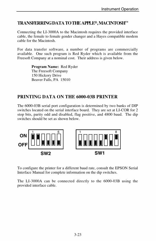
PRINTING DATA ON THE 6000-03B PRINTER
The 6000-03B serial port configuration is determined by two banks of DIPswitches located on the serial interface board. They are set at LI-COR for 2stop bits, parity odd and disabled, flag positive, and 4800 baud. The dipswitches should be set as shown below.
1 6ON
OFF
SW2
1 8
SW1
To configure the printer for a different baud rate, consult the EPSON SerialInterface Manual for complete information on the dip switches.
The LI-3000A can be connected directly to the 6000-03B using theprovided interface cable.

Instrument Operation
3-24
The LI-3000A communication parameters are set using the SET I/O routineon the MENU key. For the 6000-03B, they should be set as follows:
BAUD = 4800DATA BITS = 8STOP BITS = 2PARITY = NONECHECK DTR = YXON/XOFF = NCHECK RTS = N
Files are printed using the PRINT FILES routine which is accessed bypressing the MENU key and scrolling to the desired software routine.
SOLVING COMMUNICATION PROBLEMS
Below are a few of the common communication problems and a few thingsto check in order to facilitate solving the problem.
PROBLEM WHAT TO CHECK
Nothing Happens Proper Cable? Connections tight?Printer on-line?
All characters are wrong Check baud rate.Some characters are wrong Check data bits, stop bits, or parity.

4-1
Section IVOperation with the LI-3100 Area Meter
The LI-3000A console can be connected to the LI-3100 Area Meter usingthe following procedure.
1) Turn both instruments off.
2) Connect the 3000A-03 Interface Cable (9 pin connectors on each end) tothe LI-3100 and to the LI-3000A as shown in Figure 5 below. TheLI-3000A console can be connected directly to LI-3100's with serialnumbers LAM653 and above. For units with serial numbers LAM652and below, the 3000A-04 Interface Kit is available (includes the 3000A-03 Interface Cable). NOTE: The 3000A-04 Interface Kit requires anelectronics technician for installation, or it can be installed at LI-COR byreturning your instrument.
3) Disconnect the LI-3000A scanning head.
Figure 5. LI-3000A console connected to the LI-3100.

Operation with the LI-3100
4-2
4) Turn both instruments on.
IMPORTANT: The LI-3000A console "senses" during power onwhether the scanning head or the LI-3100 is connected. It is importantthat the interface cable be connected to both instruments before the LI-3000A is powered on.
5) After the start-up messages (see Basic Operation, Section III) you shouldset the LI-3100 resolution as explained at the end of Section III.
The LI-3000A console will now collect and display data as described in theSection III, with the exception that the reset switch on the LI-3100 now hasthe same effect as pressing the CLEAR X key.
NOTE: The LI-3100 output signal is a digital signal which is in a formthat can be interpreted by the 3000A-01 Console. The digital output is notan RS-232C output and should not be connected to an RS-232C device.

5-1
Section VMaintenance and Calibration
Cleaning the LED and PhotodiodeWindowsAs debris collects on the scanning head windows (insects, dirt, pollen, etc.),spurious numbers will accumulate on the display when the length encodingcord is drawn. This is detected by moving the cord when no sample objectis located in the scanning head. Clean the quartz windows with a moistpaper towel or cloth. Wiping the windows with a finger is usually adequatefor field use.
Cleaning the Length Encoding CordGuideA dust trap is located within the length encoding cord guide (the plasticgrommet through which the cord passes). This trap reduces dust passageinto the scanning head as the cord is retracted. The cord guide should beunscrewed from the upper scanning head section and the felt trap cleaned orreplaced. The service frequency should be determined by experience underthe most prevalent usage conditions. The interval will range from seldomunder laboratory conditions, to daily in dusty or heavily pollinating crops.
Length Encoding CordIf the length encoding cord becomes lodged, the problem is likely backlash.This seldom occurs even if the cord is released and allowed to retractrapidly. If the operator tends to "push" the cord into the head more rapidlythan the system will retract, then a slack cord occurs and backlash is moreprobable. This is corrected by loosening the cord guide and removing theseven screws on top of the scanning head. The upper section housing isthen raised straight upward. The cord is rewound and threaded according toFigure 6. When the upper section housing is replaced, do not use force.

Maintenance and Calibration
5-2
Figure 6. The length encoding cord passes from the take-up reelaround the encoding wheel.
Warning: When replacing the upper section housing do not allow contactwith the protruding edge of the LED scanner. High temperature vacuumgrease is used as a seal between the upper section housing and the baseplate. The grease is forced into the joint after the cover is attached.
Knob Separation from the LengthEncoding CordThe length encoding cord will retract completely into the scanning head ifthe knob is removed. The cord is retrieved by opening the upper housing.
Avoid continuous application of sharp angles at either end of the scanninghead cord.
Battery ReplacementAs the internal battery ages, the battery life will diminish (15 hours isnormal). Eventually the battery will fail to hold a charge and should bereplaced. If the battery is faithfully recharged when depleted, it should lasta number of years. It is not recommended that a replacement battery (model

Maintenance and Calibration
5-3
number 3000A-05) be ordered until the battery life of the first battery startsto change noticeably. If a replacement battery is ordered it should beinstalled immediately to prevent it from deteriorating in storage.
To perform the change, you will need the 3/16" nut driver included with theinstrument, a standard screwdriver, and a long nose pliers. Take thefollowing steps.
1) Unplug the AC power cord and use an anti-static work station whilechanging the battery.
2) Remove the 4 screws on the edges of the cover and carefully lift it off.Disconnect the keypad cable from the circuit board.
3) Remove the 4 hex screws from the 25 pin RS-232C connector and the 9pin LI-3100 connector.
4) Remove the 4 outermost screws on the bottom (outside) of the box.
5) Slide out the circuit board assembly.
6) Unplug the battery and quickly plug in a new one.
CAUTION: If the battery is unplugged for more than 20 seconds, thedata, date, time, and calibration may be lost.
7) Unplug the other connections on the circuit board assembly andseparate it from the box.
8) Remove the 2 battery bracket screws from the bottom (outside) of thebox.
9) Install the battery bracket on the new battery.
10) Reassemble by performing the above steps in the reverse order.
Internal FuseIf nothing happens when the LI-3000A is turned on, turn the instrument off,plug in the AC power cord and turn it on again. If the LI-3000A is stillunresponsive, check the AC fuse (AGC 0.5 amp, fast blow type) on theoutside of the instrument. If replacing the AC fuse still does not cause theinstrument to function properly, check the fuse inside the instrument. Theinterior fuse (AGC 2 amp, fast blow type) is mounted on the lower circuitboard as shown in Figure 7. Use steps 1 through 5 under batteryreplacement to disassemble the case.

Maintenance and Calibration
5-4
Figure 7. Location of the internal fuse.
Instrument StorageThe internal battery should always be fully charged before storage. Forlong term storage the battery should be recharged every 3 months to preventmemory loss.
The LI-3000A should be stored in an area that is within the temperaturerange -20 to 55 #C and has a relative humidity of 0 to 90%.
Test MenuThe TEST key accesses a list of technician test and calibration routines.
TEST: keyboard↑,↓, or ENTER
XY
These routines are generally used during the technician check-out of theLI-3000A. The list does, however, contain the calibration routine used tocalibrate a scanning head to the LI-3000A console.

Maintenance and Calibration
5-5
Test:keyboard Shows grid location of each pressed key.Test:DISPLAY Cycles through the character set.Test:prom Tests the EPROM.Test:ram Shows memory size, and does a checksum test.Test:clock freq Used to measure the accuracy of the real time clock.Test:clock Displays date and time continually.Test:RS-232 out Tests the output of the UART.Test:RS-232 inout Tests the input and output of the UART.Test:lobatt Displays low battery symbol if battery is low.Test:speedup Allows checking of U3 on the analog board.Test:thresh comp Allows checking of the comparator (U11) threshold.Master Reset Clears all data, time, date, calibration.Cal Pause Slows down calibration routine for troubleshooting.Calibrate Sensor head calibration routine.View Cal View the calibration.Cal Edit Used to change the calibration data.Print Cal Output the calibration to the RS-232C port.
To exit the TEST menu press any key except ENTER , ↑ , or ↓.
TEST: KEYBOARD
The message 'keytest' is momentarily displayed, then the display will beblank. When you press a key, the display will show the row number and thecolumn number of the pressed key. The ↑ key is 0,0 and the STORE Ykey is 3,5.
2 4 XY
3rd row down, 4th from the right.This is the "6" (or V) key.
To exit this mode, press any key three times, or press all of the keys.
TEST: DISPLAY
The console will cycle through the display's character set. If you want toquit before it finishes, press any key.
##########################################
XY
Note that the first symbol displayed isthe low battery symbol (Lo).

Maintenance and Calibration
5-6
TEST: PROM
This routine does a checksum test on the EPROM.
PROM OK XY
PROM passed the test.
Press any key to return to the menu.
TEST:RAM
This routine shows the size of the memory, and gives it a test.
32K RAMOK
XY
32K bytes memory.Displayed after a few seconds.
Press any key to return to the menu.

Maintenance and Calibration
5-7
TEST: CLOCK FREQ
This test is used to check the accuracy of the real time clock.
ADJUST FREQUENCYPRESS KEY
XY
The frequency on Pin 1 of component U24 (6242) should be 64.00000 hertzas measured by a frequency counter. Any error from 64 Hz is directlyproportional to the error that will be seen in time.
Freq. Measured Error64.01000 + 7 min/month64.00100 + 40 sec/month64.00010 + 4 sec/month64.00001 + .4 sec/month
As a part of the clock frequency test, the real-time clock is set to zero. Atthe end of the test the user is prompted to enter the current date and time.
TEST: CLOCK
20 JUN 198815:27:33
XY
Displays current date and time.
Press any key to return to the menu.
TEST: RS-232 OUT
This test transmits the character set out the RS-232C port. A printer mustbe connected. Press the ← key to abort the test if problems occur.

Maintenance and Calibration
5-8
TEST: RS-232 INOUT
This test sends a space (ASCII decimal 32) and expects or receive a space (aloopback connector must be installed). The data sent should match the datareceived.
Press ENTER to start the test. Any of the following results may occur
TEST:RS232 inout↑,↓, or ENTER
XY
Test passed. The data receivedmatched the data transmitted.
RECEIVER ERR XY
No data was received. (A loopbackconnector was not used).
RECEIVE DATA ERR XY
Data received did not matchtransmitted data.
The "receive data err" message can occur if an EPSON RX-80 printer isconnected. The RX-80 continually sends XOFF characters.
TEST:LOBATT
The low battery symbol will appear if the battery is low.
Lo LOWBATT TEST XY
Press any key to return to the menu.

Maintenance and Calibration
5-9
TEST:SPEEDUP
S SPEEDUP TEST XY
S (slow) or F(fast).
Tests component U3 on the analog board. When the string is being pulledfaster than 1/2 meter/second, then an F (fast) should appear. When theinstrument is in fast mode it no longer tries to update the display. Instead, itconcentrates only on counting area. The data is still 100% reliable and thenewest data will be displayed once the string speed slows down.
TEST: THRESH COMP
This test sets the comparator threshold voltage so it can be measured.
THRESH COMP = CAL↑,↓, or ENTER
XY
TP30 = voltage set by calibrationpotentiometer on analog board (≈0.5V).
THRESH COMP = 0.7V XY
TP30 = 0.7V.
THRESH COMP = 0.9V XY
TP30 = 0.9V.
THRESH COMP = 1.0V XY
TP30 = 1.0V.

Maintenance and Calibration
5-10
MASTER RESET
Clears all data, the time, date, and scanning head calibrations. This test isequivalent to unplugging the battery. It should be used if a new softwareprogram (EPROM U4, digital board) is installed.
CAL PAUSE
Used to slow down the calibration routine for troubleshooting.
Cal Pause↑,↓, or ENTER
XY
Press ENTER to start the routine.
Cal Pause = N↑,↓, or ENTER
XY
This will pause the calibration after allLED values are determined.
Press ↑ and then ENTER to set the pause prompt to Yes (Y).
Cal Pause = Y↑,↓, or ENTER
XY
This will pause the calibration after eachLED value isdetermined.
Press ENTER to exit the routine.
CALIBRATE
The calibration routine must be done if a different scanning head is to beused with the LI-3000A. Read the warning under the INSTRUMENTCALIBRATION heading in Section I of this manual.
Before proceeding with this test, make sure the scanning head is cleaned,and that nothing is blocking any of the LEDs.

Maintenance and Calibration
5-11
ENTER HEAD SR NO XY
Enter the sensor head serial number.
The serial number entered at this prompt is used in the start-up message("Calibrated for Head #xxxx") given when the LI-3000A is turned on.
ENTER REMARK XY
PRECALLED# 15
XY
Shows the LED that is currently beingcalibrated (0 to 127, #15 shown.
The PRECAL procedure is a first pass to approximately adjust the LEDvalues.
CALLED# 15
XY
The current of each LED is increased until its brightness provides a 1.0 voltsignal. Each LED is calibrated 4 times and then averaged.
At this point an error message will be displayed if a problem occurredduring calibration. Error messages are discussed below.
CAL DONEPRESS KEY
XY
The calibration was successful and itpassed its performance check.
Error Messages
If an error message occurs, power the LI-3000A off, then back on. Re-check the scanning head to be sure it is cleaned and free of any debris.Then do the calibration routine again. If the error message persists,contact LI-COR.
There are three error messages as listed below.

Maintenance and Calibration
5-12
2 LEDS FAILEDPRECAL: CONT? N
XY
2 LEDS FAILEDCALIBRATION
XY
WARNING: NOISYOR LOW LEDS
XY
Some of the LEDs dipped below 0.7 voltsduring the performance check.
NOTE: The following information applies to calibrations for scanningheads with serial numbers 196 or below.
Read the note in the calibration discussion in Section I.
These heads require a specially configured console (a jumper is changed)and cannot automatically be calibrated by the console. Instead, theiroriginal calibration must be used. With instruments having serial numbers196 and below, calibration is controlled by the head. With instrumentshaving serial numbers 197 and above, calibration is controlled by theconsole.
Do a calibration using the special LI-3000A console. The LED values willall be 2's. The console will think it has just calibrated the head, but inreality the original head calibration is used.
VIEW CAL
LI-3000ACALIBRATION
XY
Use ↑ and ↓ to scroll through the file.
1: 55 372L 41 29
XY

Maintenance and Calibration
5-13
The first LED is using a current level corresponding to 55 (approximately55 mA). The possible range is 0 to 255. "37" is the base 16 equivalent to55.
The ↑ and ↓ keys will scroll through the 128 calibration values. Press anykey to return to the menu.
EDIT CAL
The Edit Cal routine allows the scanning head calibration data to bechanged. Normally the calibration should never need to be manuallychanged. This routine may be of use in special cases if the head fails theautocalibration routine and the user wants to temporarily get the instrumentworking. If the instrument fails the autocalibration routine, then it does havea problem and should be returned to LI-COR for repair.
The only time it is desirable to change the calibration data is when thescanning head has a weak LED that cannot be lit to the same intensity as theother LEDs. The autocalibration routine will completely turn that LED off(its calibration value will be 0). Thus 1 mm2 of area will always becounted for each millimeter of string travel for each LED that is off. Byediting that LED to some nonzero value from 1 to 255, the LED may bemade bright enough so that it no longer causes counts to appear when thestring is pulled with an empty head. A typical value for the edited numbermay be about 100 (0 is off, 255 is brightest).
The accuracy of the instrument will generally be degraded after thecalibration file is edited. This is especially true if the edge of the leaf is nearthe edited LED. (See to the Theory of Operation. The leaf/no leaf decisionwill no longer be at 50% for that LED).
The access code to get into this routine is FP5. This code is the same for allLI-3000As. Once a number is edited, an "e" will appear next to that numberin the table. The edited calibration data can only be used until theinstrument is turned off. A "CAL FILE LOST" message is displayed if the

Maintenance and Calibration
5-14
instrument is turned off and back on, and the autocalibration routine must beused to recalibrate the head.
PRINT CAL
The calibration file is printed (via the RS-232C port) using this function.
PRINTING XY
A sample calibration table is shown on the following page.
On the 5th line of the header (noise at 0.9V is 0/12800 cnts), the 0 indicatesthat none of the LEDs dipped to 0.9V (1.0V is optimum). A non-zeronumber indicates that the head may have a few weak leads. On the 6th lineif this number is non-zero, then the calibration either failed or probablywould fail if run again.
If you encounter communication problems during printing, press the ← keyto abort the routine.

Maintenance and Calibration
5-15
LI-3000A Calibration (Sample)
HEAD SR #1611
REMARK: XXX XXX XXX
3 MAY 1988 15:42:39
NOISE AT 0.9V IS 0/12800 CNTS
NOISE AT 0.7V IS 0/12800 CNTS
CAL MAX VAL: 80
CAL MIN VAL: 42
LED DEC HEX LED DEC HEX LED DEC HEX
LED DEC HEX
1: 70 46 33: 46 2E 65: 47 2F 97: 64 40
2: 49 31 34: 54 36 66: 52 34 98: 68 44
3: 49 31 35: 52 34 67: 47 2F 99: 52 34
4: 43 2B 36: 51 33 68: 46 2E 100: 54 36
5: 48 30 37: 55 37 69: 47 2F 101: 60 3C
6: 47 2F 38: 47 2F 70: 46 2E 102: 56 38
7: 48 30 39: 44 2C 71: 48 30 103: 60 3C
8: 48 30 40: 48 30 72: 52 34 104: 64 40
9: 57 39 41: 54 36 73: 47 2F 105: 58 3A
10: 49 31 42: 53 35 74: 62 3E 106: 66 42
11: 47 2F 43: 45 2D 75: 58 3A 107: 49 31
12: 42 2A 44: 44 2C 76: 59 3B 108: 46 2E
13: 46 2E 45: 50 32 77: 66 42 109: 47 2F
14: 42 2A 46: 48 30 78: 54 36 110: 72 48
15: 43 2B 47: 48 30 79: 52 34 111: 53 35
16: 51 33 48: 56 38 80: 64 40 112: 72 48
17: 47 2F 49: 54 36 81: 57 39 113: 52 34
18: 46 2E 50: 58 3A 82: 67 43 114: 52 34
19: 45 2D 51: 46 2E 83: 50 32 115: 52 34
20: 47 2F 52: 48 30 84: 49 31 116: 54 36
21: 60 3C 53: 52 34 85: 60 3C 117: 58 3A
22: 52 34 54: 43 2B 86: 48 30 118: 53 35
23: 44 2C 55: 50 32 87: 46 2E 119: 50 32
24: 58 3A 56: 48 30 88: 57 39 120: 46 2E
25: 49 31 57: 46 2E 89: 48 30 121: 48 30
26: 46 2E 58: 50 32 90: 56 38 122: 48 30
27: 54 36 59: 49 31 91: 48 30 123: 62 3E
28: 44 2C 60: 48 30 92: 54 36 124: 46 2E
29: 45 2D 61: 46 2E 93: 52 34 125: 46 2E
30: 50 32 62: 52 34 94: 62 3E 126: 80 50
31: 50 32 63: 58 3A 95: 54 36 127: 82 34
32: 56 38 64: 48 30 96: 58 3A 128: 67 43

6-1
Section VILI-3050A Transparent
Belt Conveyer Accessory
Setup and AdjustmentLoosen the knurled knobs (1a, Figure 8) on both sides of the upper pulleyassembly. Leave the upper pulley in the down position and slide atransparent belt onto the assembly from the front. Lift the knurled knobsand tighten them when the desired belt tension is obtained.
Support the weighted lower most pulley (1b, Figure 8) with a piece of foamrubber to hold it in a maximum upward position. Slide a transparent beltonto the lower pulley assembly from the front. Remove the foam supportand center the belt while lifting the lower pulley manually. When the belt iscentered, release the lower pulley. The weight automatically providesadequate tension. Mounting the lower belt can be simplified by placing asheet of paper under the lower surface of the upper belt to prevent cohesionas the lower belt is put into place.
IMPORTANT: Place the belts so that the edges and seems of one areslightly misaligned with the other. When the edges are aligned, backgroundcounts can occur.
Turn the knurled knob on the front of the lower pulley assembly (1c, Figure8) counterclockwise to lower the scanning head support blocks. Open thescanning head and slide it into the LI-3050A (Figure 9). When the scanninghead is inserted so that about 1/8" is protruding from the front of the LI-3050A, raise the scanning head support blocks by turning the knurled knob(1c, Figure 8) clockwise against the right hand stop.
Do not lower the scanning head support blocks while the belts are moving.Only lower scanning head support blocks when the scanning head is aboutto be removed.

LI-3050A/4 Belt Conveyor
6-2
Figure 8. Transparent Belt Conveyer Accessory
Figure 9 . Scanning Head Installation.

LI-3050A/4 Belt Conveyor
6-3
Connect the LI-3050A cord into LI-3050A connector on the side panel ofthe LI-3000A. The LI-3000A must be turned off or unplugged duringthis step. Check the 115/230 voltage selection switch before turning on theLI-3000A.
The LI-3050A is turned on and off by the power switch on the LI-3000A.There is not a separate power switch on the LI-3050A. Plug the LI-3000Ainto the proper AC source and turn on the instrument.
Reset the system by pressing the white button (1d, Figure 8) located abovethe LI-3050A sample hopper. Pressing the reset button has the same effectas pressing CLEAR X on the keypad.
Allow the 10 cm2 (or 50 cm2 ) calibration disk to pass through the scanninghead. Either catch the disk as it passes out of the system or place a pad onthe instrument case. Failure to do this will eventually cause damage to thefinish.
The calibration accuracy is adjusted by turning the "CAL ADJ"potentiometer on the console using a small screwdriver (see LI-3000ATheory of Operation). The resulting reading should be very near 10 cm2 .
The purpose of the "CAL ADJ" potentiometer is not to calibrate outspurious counts on a belt system, but rather to provide 1% accuracy on aclean belt. If the belt is dirty (resulting in spurious counts), it is preferableto clean the belt rather than to turn the "CAL ADJ" potentiometer.
If the belts do not track acceptably, loosen the hex screws (1e, Figure 8) onthe front of the instrument and twist the upper pulley assembly. To produceinward belt travel, apply clockwise pressure to the upper pulley assembly(1f, Figure 8). The opposite procedure is used for the lower pulleyassembly. Do not remove the screw. Loosen them only enough so that theyremain finger tight. Probably no detectable movement will result as therotation pressure is applied to the pulley assembly. Tighten the screw andobserve the belt track. Adjust more as necessary.
Storage and MaintenanceWhen the LI-3050A is not in operation, place a block under one edge of thelower idler to remove tension from the lower belt. Release tension from theupper belt also. This prevents excessive belt stretching.
If the storage area is not very clean it is best to remove the belts prior to idleperiods of more than a few days. Wrap the belts in paper (paper towels) in amanner that prevents cohesion.

LI-3050A/4 Belt Conveyor
6-4
The transparent belts can be cleaned with warm water and hand dish-washing detergent.
Do not lubricate the drive gears. This will interfere with the optical switch(part #141) which encodes the sample length.

A-1
Appendix ALI-3000A Specifications
Resolution: 1 mm2 (1 mm x 1 mm scanning area).Accuracy: Within ± 2% for samples > 50 cm2 .Display Capacity: Area: 9,999,999.99 cm2 , Length: 99,999,999.9 cm, Width:12.8 cmDisplay: 2 line x 16 character LCDKeyboard: Sealed, 24 key tactile response.Real Time Clock: Year, month, day, hour, minute, second.
Accuracy: ± 3 minutes per month (25 °C).Internal Memory: 32K bytes RAM.Memory Capacity: From 675 entries (675 files, 1 entry each) to 2385 entries(1 file, 2385 entries).Communications: RS-232C hardwired Data Communications Equipment(DCE). Baud rates are selectable at 300, 1200, 2400, 4800, 9600.Sample Dimensions
Width: 127 mm maximum, 1 mm minimum.Thickness: 8 mm maximum.Length: 1 meter maximum.
Scanning Speed: Length encoding cord drawing speed need not be constant.Error message indicates if encoding cord is drawn too fast (> 1 meter s-1).Power Requirement: Rechargeable 6 V lead-acid battery; or 108-126/216-252 VAC, 48 to 66 Hz, 25 watt maximum.Battery Capacity: 15 hours of continuous operation.Recharging Time: 5-8 hours, instrument off. Charging circuitry built-in.Battery Voltage Sensor: Automatically shuts instrument off when low batterycondition exists. Also provides a low battery warning approximately 1 hourbefore shutdown. The remaining power maintains data stored in memory.Operating Temperature: 0 to 55 °C, 0 to 80% RH (noncondensing).Storage Temperature: -20 to 55 °C, 0 to 80% RH (noncondensing).Scanning Head
LED Light Source: 6.4 mm from outer edge.Size: 30.5 cm overall length (12.0 ").Weight 680 g (1.5 lb.).
Readout-Control UnitSize: 19.8 L x 15.5 W x 10.1 cm D (7.8" x 6.1" x 4.0").Weight: 2.0 kg (4.4 lb).

A-2
Appendix BLI-3050A Specifications
Resolution: 1 mm2 (1 mm x 1 mm scanning area).Accuracy: Within ± 1% for samples > 10 cm2 .Sample DimensionsWidth: 127 mm maximum, 1 mm minimum.Thickness: 7.5 mm maximum.Length: unlimited.Conveyer Belt Speed: 6.3 cm s-1 at 60 Hz; 5.4 cm s-1 at 50 Hz.Transparent Belts: Rugged clear vinyl.Power Requirement: 108-126/216-252 VAC, 48 to 66 Hz.Operating Temperature: 0 to 55 °C.Storage Temperature: -20 to 65 °C.Size: 27.9 H x 27.9 W x 38.1 cm L (11.0" x 11.0" x 15.0")Weight: 7.7 kg (17.0 lb).
Warranty
Each LI-COR, inc. instrument is warranted by LI-COR, inc. to be free fromdefects in material and workmanship; however, LI-COR, inc.'s soleobligation under this warranty shall be to repair or replace any part of theinstrument which LI-COR, inc.'s examination discloses to have beendefective in material or workmanship without charge and only under thefollowing conditions, which are:
1. The defects are called to the attention of LI-COR, inc. in Lincoln,Nebraska, in writing within one year after the shipping date of theinstrument.2. The instrument has not been maintained, repaired or altered by anyonewho was not approved by LI-COR, inc.3. The instrument was used in the normal, proper and ordinary manner andhas not been abused, altered, misused, neglected, involved in an accident ordamaged by act of God or other casualty.4. The purchaser, whether it is a DISTRIBUTOR or direct customer ofLI-COR or a DISTRIBUTOR'S customer, packs and ships or delivers theinstrument to LI-COR, inc. at LI-COR inc.'s factory in Lincoln, Nebraska,U.S.A. within 30 days after LI-COR, inc. has received written notice of thedefect. Unless other arrangements have been made in writing,transportation to LI-COR, inc. (by air unless otherwise authorized byLI-COR, inc.) is at customer expense.5. No-charge repair parts may be sent at LI-COR, inc.'s sole discretion tothe purchaser for installation by purchaser.6. LI-COR, inc.'s liability is limited to repair or replace any part of theinstrument without charge if LI-COR, inc.'s examination disclosed that partto have been defective in material or workmanship.
There are no warranties, express or implied, including but not limitedto any implied warranty of merchantability of fitness for a particularpurpose on underwater cables or on expendables such as batteriesand lamps .
Other than the obligation of LI-COR, inc. expressly set forth herein,LI-COR, inc. disclaims all warranties of merchantability or fitness for aparticular purpose. The foregoing constitutes LI-COR, inc.'s soleobligation and liability with respect to damages resulting from the useor performance of the instrument and in no event shall LI-COR, inc. orits representatives be liable for damages beyond the price paid for theinstrument, or for direct, incidental or consequential damages.
The laws of some locations may not allow the exclusion or limitation onimplied warranties or on incidental or consequential damages, so thelimitations herein may not apply directly. This warranty gives you specific

legal rights, and you may already have other rights which vary from state tostate. All warranties that apply, whether included by this contract or by law,are limited to the time period of this warranty which is a twelve-monthperiod commencing from the date the instrument is shipped to a user who isa customer or eighteen months from the date of shipment to LI-COR, inc.'sauthorized distributor, whichever is earlier.
This warranty supersedes all warranties for products purchased prior to June1, 1984, unless this warranty is later superseded.
DISTRIBUTOR or the DISTRIBUTOR's customers may ship theinstruments directly to LI-COR if they are unable to repair the instrumentthemselves even though the DISTRIBUTOR has been approved for makingsuch repairs and has agreed with the customer to make such repairs ascovered by this limited warranty.
Further information concerning this warranty may be obtained by writing ortelephoning Warranty manager at LI-COR, inc.
IMPORTANT: Please return the User Registration Card enclosed withyour shipment so that we have an accurate record of your address. Thankyou.
Obtaining Service for Your InstrumentIf, after following the operational and maintenance procedures in theinstruction manual, you determine that your instrument is in need of service,you can help assure efficient servicing by following these guidelines:
• Some instrument problems can be resolved by discussing them withLI-COR on the telephone. If you would like to talk to someone aboutservicing your instrument before you return it, please give us a call at(402) 467-3576.
• If you have a electronic technician available, you may want to considerthe 3000A/SM Service Manual for the LI-3000A. This manual containsthe schematic diagrams, component layouts and designator lists for the

LI-3000A. It is designed to isolate electronic problems to the scanninghead or to a specific board in the console. Contact LI-COR forinformation on ordering circuit board replacements.
• If you need to ship your instrument, use the original shipping carton or apackage that provides adequate protection. The package should beinsured for the value of the instrument against damage and loss. Werecommend that you ship your packages air freight for the bestprotection (in the U.S. ship via air freight, parcel post, or United ParcelService).
• For customers outside the U.S., contact your local LI-COR distributor oragent (if any) before returning your instrument.
• If you would like someone from LI-COR to contact you with a time orcost estimate before beginning your repair, please let us know byenclosing a letter with your instrument.
• Warranty repairs are invoiced at no charge (excluding customs fees insome countries). Other repairs are billed at an hourly rate for technicianlabor plus the cost of replacement parts. Recalibrations are billed at thestandard prices indicated on the LI-COR price list. For repairs that arenot under warranty, please include billing information when you returnyour instrument.

LI-COR, inc. � 4421 Superior Street � P.O. Box 4425 � Lincoln, Nebraska 68504 USAPhone: 402-467-3576 � FAX: 402-467-2819
Toll-free 1-800-447-3576 (U.S. & Canada)
®